
Fortwo Cabrio Electric Drive (2018) - Automotive SMART - Free user manual and instructions
Find the device manual for free Fortwo Cabrio Electric Drive (2018) SMART in PDF.


| Product Type | Electric vehicle |
| Brand | Smart |
| Model | Fortwo Cabrio Electric Drive (2018) |
| Category | Automotive |
| Body Style | Convertible (Cabrio) |
| Seats | 2 |
| Drivetrain | Rear-wheel drive |
| Electric Motor | 60 kW (82 hp) AC synchronous |
| Battery Capacity | 17.6 kWh lithium-ion |
| Range (NEDC) | 160 km (100 mi) |
| Charging Time (Standard AC) | 6 hours (3.3 kW) |
| Charging Time (Fast Charge) | 50 minutes (22 kW) |
| Top Speed | 130 km/h (81 mph) |
| Dimensions (L x W x H) | 2.69 m x 1.66 m x 1.55 m |
| Curb Weight | 975 kg |
| Cargo Volume | 190 L |
| Tires | 165/65 R15 |
| Safety Systems | ABS, ESP, front airbags |
| Convertible Top | Electric fabric soft top |
| Maintenance | Regular checks of electric system, tires, brakes; battery warranty 8 years/100,000 km |
| Regenerative Braking | Yes |
Frequently Asked Questions - Fortwo Cabrio Electric Drive (2018) SMART
User questions about Fortwo Cabrio Electric Drive (2018) SMART
0 question about this device. Answer the ones you know or ask your own.
Ask a new question about this device
Download the instructions for your Automotive in PDF format for free! Find your manual Fortwo Cabrio Electric Drive (2018) - SMART and take your electronic device back in hand. On this page are published all the documents necessary for the use of your device. Fortwo Cabrio Electric Drive (2018) by SMART.
USER MANUAL Fortwo Cabrio Electric Drive (2018) SMART
Order no. 6522 0225 13 Part no. 453 584 81 09 Edition A-2018

smart fortwo coupe and smart fortwo cabrio electric drive Operator's Manual
natural_image
Two black compact cars with green accents displayed on a white pedestal, with a smart logo in the corner (no text or symbols on the cars themselves)
>> Operator's Manual
smart fortwo coupe and smart fortwo cabrio electric drive
Symbols in the Operator's Manual
Registered trademarks:
- Android ^TM is a registered trademark of Google, Inc.
- Android Auto™ is a registered trademark of Google, Inc.
- Apple® iOS and iPod are registered trademarks of Apple, Inc.
- Bass boost arkamys is a registered trademark of Arkamys.
- Bluetooth ^® is a registered trademark of Bluetooth SIG Inc.
- ESP ^ is a registered trademark of Daimler AG.
- IQ Routes™ is a registered trademark of TomTom International B.V.
- MirrorLink™ is a registered trademark of the Car Connectivity Consortium.
The following symbols are used in this Operator's Manual:

WARNING
Warning notes make you aware of dangers which could pose a threat to your health or life, or to the health and life of others.

Environmental note
Environmental notes provide you with information on environmentally aware actions or disposal.
Notes on material damage alert you to dangers that could lead to damage to your vehicle.
i Practical tips or further information that could be helpful to you.
▶ Instructions that must be followed.
Several consecutive symbols indicate an instruction with several consecutive steps. (D page) Further information on a topic A warning or an instruction that is continued on the next page.
Display text: Display text in the instrument cluster display, the smart Audio-System or the smart Media-System.
Publication details
Internet
Further information about smart vehicles and about Daimler AG can be found on the following websites: http://www.smart.com http://www.daimler.com
Editorial office
^c Daimler AG: not to be reprinted, translated or otherwise reproduced, in whole or in part, without written permission from Daimler AG.
Vehicle manufacturer
Daimler AG Mercedesstraße 137 70327 Stuttgart Germany
About this Operator's Manual
We urge you to read this Operator's Manual carefully and familiarize yourself with the vehicle before driving. For your own safety and a longer vehicle life, follow the instrucyour vehicle and multimedia system online on your phone or as a download regardless of the status of your network connection. Available for smartphones and tablets.
tions and warning notices in this Operator'sPlease note that the smart guides app may Manual. Ignoring them could result in dam-not currently be available in your country. age to the vehicle or personal injury to you or others.
This Operator's Manual provides information on the most important functions of your vehicle.
The equipment or product designation of your vehicle may vary depending on:
- Model
- Order
• Country specification - Availability
The illustrations in this Operator's Manual show a left-hand-drive vehicle. On right-hand-drive vehicles, the layout of components and controls differs accordingly.
smart reserves the right to introduce changes in the following areas:
- Design
- Equipment
- Technical features
The equipment in your vehicle may therefore differ from that shown in the descriptions and illustrations.
Integral parts of the vehicle include:
- Operator's Manual
- Maintenance Booklet
• Equipment-dependent Supplements
Keep copies of the documents in the vehicle at all times. If you sell the vehicle, always pass all documents on to the new owner.
Your Operator's Manuals:

Digital on the Internet
The Operator's Manual on the Internet provides you with convenient access to all of the information relevant to your vehicle and multimedia system. It also offers helpful animations, exciting background information and various search options.

Digital as an app
Using the smart guides app, you can call up all of the information relevant to
Index 4
Introduction 19
Protection of the environment 19
smart genuine parts 19
Warranty for the smart Audio-System and smart Media-System .... 20
Vehicle equipment 20
Service and vehicle operation 20
Operating safety 21
QR codes for rescue card 2
Data stored in the vehicle 24
Information on copyright 2
At a glance 27
Dashboard 27
Multifunction steering wheel 28
Center console with drawer 29
Overhead control panel 3
Door control panel 3
Displays shown in the instrument cluster and the display .... 3
Safety 33
Activating and deactivating the panic alarm 33
Occupant safety 33
Children in the vehicle 42
Pets in the vehicle 45
Driving safely 45
Entering and setting up 48
Understanding functions of the SmartKey 48
Opening the door 48
Correct driver's seat position 48
Adjusting the seats 49
Adjusting the mirrors 50
Driving 52
Starting the engine 52
Pulling away 52
Automatic transmission 54
Using the turn signals 55
Acoustic presence indicator 55
Driving economically 56
Braking correctly 59
Driving on wet roads 60
Winter driving 60
Using cruise control 60
Charging the high-voltage battery ..... 61
Ensuring good visibility 69
Switching on the lighting 69
Using the interior lighting 70
Using the windshield wiper 71
Folding the sun visor to the side ..... 725
Feeling comfortable in the vehicle
interior 73
Locking and unlocking the doors from the inside 73
Understanding the reversing fea- 0ture 73
10Opening and closing the windows ..... 74
Using the soft top (smart fortwo &abrio) 75
Installing and removing the wind screen (smart fortwo cabrio) 78
Operating the climate control system 78
Activating/deactivating the seat heating and steering wheel heating ... 80
Using the accessories 81
Parking and getting out 83
Parking 83
Using the rear view camera 83
Locking the vehicle 84
Arming and disarming the anti-theft alarm system 84
Operating the on-board computer ..... 85
Overview of the on-board computer ... 85
Calling up displays 85
Setting values 87
Using the smart Audio-System 89
Operating and setting the smart Audio-System 89
Listening to the radio 91
Using a mobile phone 92
Operating external data carriers ..... 94
Using the smart Media-System 96
Operating and setting up the smart Media-System 96
Listening to the radio 100
Calling up electric drive displays ..... 101
Using a mobile phone 102
Connecting and operating external data carriers 106
Viewing images 108
Video playback 109
Using the navigation system ..... 109
Managing apps 119
Loading and stowing 121
Stowing small objects 121
Stowing luggage and large objects ... 122
Using the trunk partition 124
Removing/installing the charging cable bag 125
Observing the tire and loading information 126
Maintenance and care 129
Useful information 1 29
Removing/installing the subwoofer .. 129
Opening and closing the service cover 129
Checking and adding service products 131
Checking wheels and tires 132
Obtaining information on tires ..... 133
Changing a wheel 139
Using the tire pressure monitor ..... 143
Checking the tire pressures 144
Using winter tires 147
Using snow chains 1 47
Changing the window wiper blades .. 148
Cleaning the vehicle 149
Observing service due dates 153
Parking the vehicle for a long period 153
Dealing with accidents and break- downs 154
Securing the vehicle in the event of an accident or a breakdown 1 54
Removing the vehicle tool tray ..... 155
Sealing tires using the TREFIT kit ... 155
Towing the vehicle 157
Manually releasing the selector lever lock 159
Replacing the bulbs 160
Changing fuses 162
Replacing the SmartKey battery ..... 163
Opening a door with the emergency release 164
Locking the doors in an emergency .. 164
Practical advice 166
Notes on display messages 166
Locking and unlocking 166
Visibility, occupants, air bags 168
Engine, brakes, transmission ..... 170
Charging process 172
Driving safety systems 175
Driver assistance systems 180
Battery, lights, heating 181
smart Audio-System and smart Media-System 183
Technical data 185
Obtaining technical data 185
Reading out vehicle data 185
Service products 186
Climate control system refrigerant ... 186
Bulb types 187
Fuse allocation 188
Radio type approvals for the tire pressure monitor 190
Installing two-way radios and mobile phones 190
1, 2, 3 ...
12 V socket
see Socket (12 V)
A
ABS (Anti-lock Braking System)
Display message 175
Function/notes 45
Warning lamp (yellow) 175
Acceleration
see Kickdown
Acoustic presence indicator
Function/notes 55
Air bag
Installation locations 37
Limited protection 38
Overview 37
Air bags
Deployment 34
Front air bag (driver, front passenger) 37
Head bag 37
Knee bag 37
PASSENGER AIR BAG indicator lamps 39
Protection provided 38
Side impact air bag 37
Window curtain air bag 37
Air distribution
Setting (automatic climate control) 79
Air pressure
see Tire pressure
Air vents
Important safety notes 80
Setting 80
Air-recirculation mode
Switching on/off (automatic climate control) 79
Alarm
Anti-theft alarm system 84
Switching off 84
Ambient lighting
Setting the brightness 88
Switching on/off 88
Android Auto™
Using 105
Animals
see Pets in the vehicle
Anti-entrapment feature
see Reversing feature
Anti-lock Braking System
see ABS (Anti-lock Braking System)
Anti-skid chains
see Snow chains
Anti-theft alarm system
Switching off the alarm 84
Switching on/off 84
Apps
Displaying/calling up 120
General notes 119
Installing 119
Ashtray 81
Audio-System
Connecting a mobile phone 92
Connecting Bluetooth ^® audio devices 95
Connecting external audio equipment (AUX) 95
Operating 89
Operating the radio 91
Operating via the mobile phone .... 90 Overview .... 89
Setting the time 90
Smartphone bracket 90 System settings 90
Troubleshooting 1 83
Using external devices 89
Volume/sound settings 91
Warranty 20
Authorized workshop
see Qualified specialist workshop
Automatic car wash (care) 149
Automatic climate control
Activating/deactivating air-recirculation mode 79
Cooling with air dehumidification 79
Defrosting the rear window 79
Defrosting the windshield 79
Increasing/decreasing the blower speed 79
Setting air distribution 79
Setting the temperature 79
Switching on/off 78
Windows fogged up 79
Automatic headlamp mode 69
Automatic transmission
Engaging neutral 55
Engaging reverse gear 55
Engaging the park position 55
Important safety notes 54
Kickdown 55
Manually releasing the selector lever lock 1 59
Pulling away 52
Starting the engine 52
Transmission positions 55
AUX jack
Audio-System 89
Media-System 96
B
Battery
Display message 181
Battery
see High-voltage battery
Battery (SmartKey)
Important safety notes 163
Replacing 163
Battery (vehicle)
see High-voltage battery
Belt
see Seat belt
Belt warning 37
Blower speed
Increasing or decreasing (automatic climate control) 79
Bluetooth®
Activating the mobile phone (Audio-System) 92
Activating the mobile phone (Media-System) 102
Authorizing the function for the mobile phone (Audio-System) ..... 92
Connecting a device (Media-System) 107
Operating (Audio-System) 95
Switching on/off (Media-System) 102
Brake fluid
Display message 171
Brake force distribution
see EBD (electronic brake force distribution)
Brake lamp
Replacing bulbs 1 61
Brake lamps
Display message 182
Brakes
ABS 45
Braking on downhill gradients ..... 59
Braking on wet road surfaces ..... 59
EBD 47
Important safety notes 59
Limited braking performance on salt-treated roads 59
Parking brake 53
Riding tips 59
Warning lamp 171
Breakdown
Towing away 157
see Flat tire
C
Car
see Vehicle
Car wash
see Care
Care
Car wash 149
Carpets 152
Cleaning the interior 151
Cleaning the roof lining (smart fortwo coupe) 152
Display 151
Exterior 1 49
Exterior lights 151
High-voltage battery 63
Interior 151
Notes 149
Paint 151
Plastic trim 152
Power washer 149
Roof lining 151
Seat belt 152
Seat cover 152
Selector lever 152
Sensors 150
Soft top system 151
Steering wheel 1
Trim pieces 153
Washing by hand 149
Wheels 150
Windows 150
Wiper blades 150
Center console
Overview 29
Central locking
Automatic locking 73
Locking/unlocking (SmartKey) ..... 84
Changing bulbs
see Replacing bulbs
Changing the route
Navigation 113
Charge current
Setting (charging cable) 65
Charge level display 57
Charging cable
Connecting 66
Controls 65
Display message 172
Removing 67
Storing 68
Warming up 64
Charging cable bag
Removing/fitting 1 25
Charging current
Display messages 172
Child seat
Forward-facing restraint system 44
On the front-passenger seat ...... 44
Rearward-facing restraint system 44
Top Tether 43
Children
Restraint systems 42
Special seat belt retractor 43
Cigarette lighter 81
Cleaning
see Care
Climate control
Automatic climate control 78
General notes 78
Refrigerant 186
Refrigerant filling capacity ..... 187
Setting the air vents 80
Clock
Setting the time (Media-System) 98
Cockpit
Overview 27
COMAND display
Cleaning 151
Connectivity manager 120
Consumption details
Calling up (Media-System) ...... 102
Controlling speed
see Cruise control
Coolant
Checking the coolant level and adding coolant 131
Important safety notes 131
Cooling
see Climate control
Cooling with air dehumidification
Automatic climate control 79
Copyright 26
Cornering light function 70
Cover (front)
see Service cover
Crosswind Assist 46
Cruise control
Activating 61
Buttons 61
Calling up the speed last stored 61
Canceling cruise control 61
Deactivating 61
Display message (color display) .. 181
Function/notes 60
General notes 60
Important safety notes 60
Increasing/decreasing the speed 61
Storing and maintaining current speed 61
Cup holder
Center console 121
Important safety notes 121
Customer Assistance Center (CAC) ..... 24
Customer Relations Department 24
D
Dashboard
see Cockpit
Data
see Technical data
Data carriers
see External data carriers
Data sharing
Managing 120
Daytime running lamp mode
see Daytime running lights
Daytime running lights 69
Dealership
see Qualified specialist workshop
Declarations of conformity 22
Diagnostics connection 22
Digital speedometer
Displaying 88
Display
Color 85
Display message
Color display 87
Display messages
General notes 166
Distance warning function
Function/notes 45
Warning lamp 180
Door
Unlocking (SmartKey) 48
Doors
Automatic locking (switch) 73
Central locking/unlocking (SmartKey) 84
Control panel 31
Display message 167
Emergency locking 165
Emergency unlocking 164
Opening (from inside) 73
Drinking and driving 53
Driver's door
see Doors
Driver's seat
see Seat
Driving economically
eco score display 57
General notes 56
Driving noise
see Acoustic presence indicator
Driving safety system
Crosswind Assist 46
Limits of the driving safety systems 45
Driving safety systems
ABS (Anti-lock Braking System) .... 45
Distance warning function 45
EBD (electronic brake force distribution) 47
ESP ^® (Electronic Stability Program) 46
ETS (Electronic Traction System) 46
Driving systems
Cruise control 60
Driving tips
Brakes 59
Downhill gradient 59
Drinking and driving 53
Driving in winter 60
Driving on flooded roads 60
Driving on wet roads 60
Hydroplaning 60
Icy road surfaces 60
Limited braking efficiency on salted roads 59
Pulling away 52
see Driving economically
Dynamic handling control system
see ESP ^® (Electronic Stability Program)
E
EBD (electronic brake force distribution)
Function/notes 47
EBD (Electronic Brake-force Distribution)
Indicator lamp 175
ECO mode
Switching on/off 56
eco score
Calling up 57
Comparing a trip 58
Display (color display) 57
Evaluating the current trip 58
Function/notes 57
Resetting data 58
Saving a trip 58
Electronic Brake-force Distribution
see EBD (electronic brake force distribution)
Electronic Stability Program
see ESP ^® (Electronic Stability
Program)
Electronic Traction System
see ETS (Electronic Traction System)
Emergency release
Driver's door 164
Vehicle 164
Emergency Tensioning Devices
Activation 3 4
Energy
Displaying the current con- sumption (color display) 86
Energy consumption
High-voltage battery 63
Energy flow display
Calling up (Media-System) 101
Color display 86
Engine
Starting problems 170
Starting the engine with the SmartKey 52
Switching off 83
Engine electronics
Notes 2
Entering a destination
Navigation 110
Environmental protection
High-voltage battery 19
ESP® (Electronic Stability Program)
Crosswind Assist 46
Display message 176
General notes 46
Important safety information ..... 46
Warning and indicator lamps ..... 176
ETS (Electronic Traction System) ..... 46
Exterior lighting
Cleaning 151
see Lights
Exterior mirrors
Adjusting 51
Out of position (troubleshooting) 168
External audio equipment (AUX)
Connecting (Audio-System) 95
External data carriers
Connecting (Audio-System) 89
Connection (Media-System) ..... 107
Operating (Audio-System) 94
see Front wheel arch
Flat tire
Preparing the vehicle 154
TREFIT kit 155
Floormats 82
Fog lamps
Switching on/off 70
Fording
On flooded roads 60
Forward collision warning
Display message 180
Frequencies
1 Mobile phone 190
Two-way radio 190
Front air bag 37
Front cover
see Service cover
Front wheel arch
Removing/installing the cover .... 160
Front wheel arch cover
Installing/removing 160
Front-passenger front air bag
deactivation system
PASSENGER AIR BAG indicator lamps 39
Status indicator 39
Front-passenger seat
Folding down 124
Front-passenger seat
see Seat
Frontal area cover
see Service cover
Fuses
Allocation chart 188
Before changing 163
Dashboard fuse box 163
Important safety notes 162
Opening the fuse box 163
G
Genuine parts 19
Glove box 122
H
Hand brake
see Parking brake
Hands-free system
see Mobile phone
Hazard warning lamps
Switching on/off 154
Head bags 37
Headlamps
see Automatic headlamp mode
Heating
see Climate control
High beam flasher 69
High-beam headlamps
Replacing bulbs 160
Switching on/off 69
High-voltage battery
Battery care 63
Charge level display 56
Charging (charging station) 67
Charging (mains socket) 65
Charging cable warming 64
Condition of charge 56
Cruise range 63
Discharged battery 63
Display message 181
Energy consumption 63
Important safety notes 61
Indicator lamp (vehicle socket) ..... 64
Method of operation 63
Outside temperatures 63
Problems with the charging
process 172
Protective equipment 64
READY indicator 181
Terms of use 64
Vehicle socket 64
Warning and indicator lamps ..... 181
High-voltage electrical system
Automatic switch-off 23
Danger of electric shock 23
Operating safety 23
Vehicle fire 24
Home address
Entering and saving 111
Home address (navigation)
see Home address
Hydroplaning 60
I
i-Traffic
Traffic reports 101
Ignition lock
see Key positions
Image
Playback (Media-System) 108
Immobilizer 84
Indicator and warning lamps
Battery 181
Indicator lamps
see Warning and indicator lamps
Instrument cluster
Overview 32
Warning and indicator lamps ..... 32
Instrument cluster lighting
Adjusting 88
Instrument lighting
see Instrument cluster lighting
Interior lighting 70
Replacing bulbs 162
Setting the ambient lighting ..... 88
Setting the ambient lighting
(color display) 71
Switching on/off 70
Intermittent wiping 71
J
Jack
Using 140
K
Key
Position in the ignition lock ..... 52
Keyboard
Changing (Media-System) 98
Kickdown 55
Knee bag 37
L
Lamps
see Warning and indicator lamps
Language
Selecting (Media-System) 98
Language (on-board computer) 88
License plate lamp
Changing bulbs 162
Lighting
Setting the ambient lighting ..... 88
Lights
Automatic headlamp mode 69
Cornering light function 70
Display message 182
Fog lamps 70
Hazard warning lamps 154
High beam flasher 69
High-beam headlamps 69
Light switch 69
Low-beam headlamps 69
Parking lamps 70
Rear fog lamp 70
Turn signals 55
see Interior lighting
see Replacing the bulbs
Loading guidelines 122
Locking
see Central locking
Locking (doors)
Automatic 73
Emergency locking 165
From inside (central locking
button) 7 3
Loudspeaker
see Subwoofer
Low-beam headlamps
Replacing bulbs 160
Switching on/off 69
M
M+S tires (winter tires) 147
Making a call
Media-System 103
Malfunction message
see Display message
Manually releasing the selector
lever lock (automatic transmission) ... 159
Media system
Creating favorites 100
System menu 98
System settings 98
Volume/tone settings 99
Media-System
Buttons on the multifunction
steering wheel 96
Calling up menus 97
Changing the on-screen key-
board 98
Connectivity manager 120
Consumption details 102
Controls 96
Data connectivity 119
Display settings 98
eco score 57
Enabling data sharing 120
Energy flow display 101
Home screen 97
Image playback 108
Installing apps 119
Navigation menu 109
Navigation system 109
Operating the radio 100
Overview 96
Problem solving 183
Selecting the home screen dis-
play 98
Selecting the language 98
Setting the time 98
Setting warning tones 99
Status and information 98
Switching on/off 97
Video playback 109
Warranty 20
Message memory (color display) 87
Mirror
see Exterior mirrors
MirrorLink™
Using 104
Mirrors
see Rear-view mirror
Mobile phone
Automatically downloading data (Media-System) 103
Connecting (Audio-System) 92
Connecting (Media-System) ..... 102
Frequencies 190
Installation 190
Loading and updating the phone book (Audio-System) ..... 93
Setting the sound (Audio-System) 93
Transmission output (maxi- mum) 190
Using Android Auto™ 105
Using MirrorLink™ 104
Using the telephone (Media-System) 103
Using voice control (Audio-System) 94
Using voice control (Media-System) 106
Model series
see Vehicle identification plate
Mounting wheels
Mounting a new wheel 142
Preparing the vehicle 140
Raising the vehicle 140
Removing a wheel 140
Securing the vehicle against rolling away 154
Multi-functional seat
see Seat
Multifunction steering wheel
Overview 28
N
Navigation
Alternative route 113
Changing the route 113
Current location 1 16
Destination memory 111
Displaying the reachability map 116
Entering a charging station as a destination 111
Entering a destination 110
Entering a destination by address 110
Entering a destination using geo-coordinates 1 11
Entering a destination using the map 1 10
Entering a point of interest ..... 111
Entering/saving your home address 111
Reading map data 109
Route details 113
Selecting a destination from thelist of last destinations ..... 111
Setting route planning 114
Setting the voice 118
Starting 109
Starting route calculation 112
Switching announcements on/off 114
System settings 1 18
TomTom Services 116
Traffic information 115
Troubleshooting 1 83
Way points 113
0
Occupant safety
Air bags 37
Belt warning 37
Children in the vehicle 42
PASSENGER AIR BAG indicator lamps 39
Pets in the vehicle 45
Restraint system 3 3
Restraint system warning lamp .... 33
Seat belt 35
On-board computer
Calling up displays (color display) 85
Important safety notes 85
Operation 85
Overview 85
Selecting the language 88
Setting/resetting values (color display) 8
On-board diagnostic interface
see Diagnostics connection
On-screen keyboard
Changing (Media-System) 98
Operating safety
Declaration of conformity 22
High-voltage electrical system ..... 23
Operating system
see On-board computer
Operator's Manual
Vehicle equipment 20
Outside temperature display 85
Setting the units 88
Outside temperatures
High-voltage battery 63
Overhead control panel 30
Overvoltage protection
High-voltage battery 64
P
Paint code number 185
Paintwork (cleaning instructions) ..... 151
Panic alarm 33
Park brake
see Parking brake
Parking 83
Engaging park position 55
Important safety notes 83
Parking brake 53
Rear view camera 83
Parking brake
Display message 171
General notes 53
Warning lamp 171
Parking lamps
Switching on/off 70
PASSENGER AIR BAG
Indicator lamps 39
Problem (malfunction) 169
Pets in the vehicle 45
Point of interest
Entering 111
Power display 57
Power windows
see Side windows
Pre-entry climate control and
charging
Color display 87
Pre-entry climate control at depar-
ture time
Setting departure time 79
Smart-Charging 79
Protection against theft
Anti-theft alarm system 84
Protection of the environment
General notes 19
Pulling away
General notes 52
Hill start assist 54
Q
QR code
Rescue card 24
Qualified specialist workshop 23
R
Radio
Display mode 100
i-Traffic (traffic reports) 101
Operating (Audio-System) 91
Radio type approvals
Tire pressure monitor 190
Radio-wave reception/transmis-
sion in the vehicle
Declaration of conformity 22
Rain and light sensor (display mes-
sage) 182
Rain sensor 71
Range
High-voltage battery 63
Reading lamp 70
Rear fog lamp
Replacing bulbs 161
Switching on/off 70
Rear lamp
Replacing bulbs 161
Rear soft top
Closing 123
Opening 123
Rear window defroster
Defrosting the rear window (automatic climate control) 7
Rear window wiper
Automatic rear window wiper when backing up 72
Replacing the wiper blade ..... 1
Switching on/off 72
Rear-view mirror 50
Anti-glare (manual) 50
Dipping (automatic) 50
Recycling
see Protection of the environment
Refrigerant (air-conditioning sys-
tem)
Important safety notes 186
Replacing bulbs
Brake lamp 161
High-beam headlamps 160
Important safety notes 160
Installing/removing the cover (front wheel arch) 160
Interior lighting 162
LED 161
License plate lamp 162
Low-beam headlamps 160
Overview of bulb types 187
Rear fog lamp 161
Rear lamp 161
Reversing lamp 161
Turn signal lamp (rear) 161
Replacing the bulb
Turn signal lamp (front) 160
Rescue card 24
Restraint system
Display message 169
Function during an accident 34
Limited protection 33
Operational readiness 33
Protection provided 33
System self-test 33
Warning lamp 169
Warning lamp (function) 33
Restraint systems
Malfunction 33
Reverse gear
Engaging (automatic transmission) 55
Reversing feature
Side windows 73
Reversing lamp
Replacing bulbs 161
Roadside Assistance (breakdown) ..... 20
Roof lining and carpets (cleaning
4guidelines) 152
S
Safety
Children in the vehicle 42
see Occupant safety
see Operating safety
Safety system
see Driving safety system
SD card
Connecting (Media-System) ..... 107
Reading map data 109
SD card slot 96
Seat
Correct driver's seat position ..... 48
Folding the front-passenger seat down 124
Seat belt
Limited protection 35
Protection provided 35
Seat belts
Cleaning 152
Fastening 36
Releasing 36
Warning lamp 168
Warning lamp (function) 37
Seat heating 80
Seats
Adjusting (manually) 49
Cleaning the cover 152
Important safety notes 49
Switching seat heating on/off ..... 80
Selector lever
Cleaning 152
Selector lever
see Automatic transmission
Sensors (cleaning instructions) ..... 150
Service appointment
Display message 172
Service Center
see Qualified specialist workshop
Service cover 129
Service display
Calling up (color display) 87
Service products
Brake fluid 186
Coolant (engine) 131
Important safety notes 131
Refrigerant (air-conditioning
system) 186
Washer fluid 186
Side bars
Closing the stowage well 77
Mounting 77
Removing 76
Stowing 7
Side impact air bag 37
Side turn signal lamps
Replacing bulbs 161
Side windows
Cleaning 150
Important safety information ..... 74
Opening/closing 74
Problem (malfunction) 167
Resetting 167
Reversing feature 73
smart center
see Qualified specialist workshop
Smart-Charging
Function/notes 79
SmartKey
Changing the battery 163
Loss 166
Opening the soft top 76
Problem (malfunction) 166
Starting the engine 52
SmartKey positions (ignition lock) ..... 52
Smartphone
Inserting/removing 90
Installing the bracket 90
Operating the Audio-System via the mobile phone 90
Smartphone Screen
Setting (Media -System) 104
Snow chains 147
Socket (12 V)
Center console 82
Socket (high-voltage battery)
see Vehicle socket
Soft top
Cleaning 1 51
Closing 75
Closing the rear soft top 1 23
Closing the stowage well with-out the side bars 77
Important safety notes 75
Opening 75
Opening the rear soft top 123
Removing the side bars 76
Stowing the side bars 76
Sound
Setting (Audio-System) 91
Setting (Media-System) 99
6 Sound generator
see Acoustic presence indicator
Speakers
see Subwoofer
Special seat belt retractor 43
Specialist workshop 23
Speedometer
Digital 85
Displaying (digital speedometer) 88
General information (digital speedometer) 87
see Instrument cluster
Starting (engine) 52
Starting the engine
see Starting (engine)
Station
Setting (Media-System) 101
Station list
Updating (Media-System) 101
Station search
Audio-System 92
Stations
Setting (Audio-System) 91
Setting a stored station (Audio-System) 92
Setting the station list (Audio-System) 91
Storing (Audio-System) 92
Steering
Display message 179
Warning lamps 1 79
Steering wheel
Button overview 2
Cleaning 152
Steering wheel heating
Switching on/off 80
Stowage areas 121
Stowage compartment in the tail-
gate 122
Stowage compartments
Center console 121
Cup holders 121
Door 121
Eyeglasses compartment 121
Glove box 121
Important safety information ..... 121
Subwoofer
Fitting/removing 129
Sun visor 72
T
Tailgate
Opening dimensions 185
Opening/closing 123
Warning lamp 167
Tailgate (smart fortwo cabrio)
Opening/closing 123
Technical data
Information 185
Vehicle data 185
Telephone book
Loading (Audio-System) 93
Telephone operation
Audio-System 93
Temperature
Setting (automatic climate control) 79
Time
Setting (Audio-System) 91
Setting (color display) 88
Setting the time format (color display) 88
Tire pressure
Checking/correcting 146
Display message 177
Important safety notes 144
Not reached (TREFIT) 156
Reached (TREFIT) 157
Recommended 144
8Tire pressure monitor
Function/notes 143
Radio type approval for the tire pressure monitor 190
Restarting 143
Starting 88
Warning lamp 177
TIREFIT kit 155
Tires
Aspect ratio (definition) 138
Average weight of the vehicle occupants (definition) 137
Bar (definition) 137
Changing a wheel 139
Characteristics 137
Checking 132
Curb weight (definition) 138
Definition of terms 1 37
Direction of rotation 142
Distribution of the vehicle occupants (definition) .... 139
DOT (Department of Transportation) (definition) 137
GAWR (Gross Axle Weight Rating) (definition) 1 38
GVW (Gross Vehicle Weight) (definition) 138
GVWR (Gross Vehicle Weight Rating) (definition) 138
Important safety notes 132
Increased vehicle weight due to optional equipment (definition) .. 138
Kilopascal (kPa) (definition) ..... 138
M+S tires (winter tires) 147
Maximum load on a tire (definition) 1 38
Maximum loaded vehicle weight (definition) 138
Maximum permissible tire pressure (definition) 138
Maximum tire load 136
Maximum tire load (definition) .... 138
Optional equipment weight (definition) 139
PSI (pounds per square inch) (definition) 138
Rules for new tires 140
Service life 140
Sidewall (definition) 139
Snow chains 147
Speed rating (definition) 138
Storing 143
Structure and characteristics (definition) 137
Temperature 134
TIN (Tire Identification Number) (definition) 139
Tire bead (definition) 139
Tire pressure (definition) 139
Tire pressures (recommended) ..... 138
Tire size designation, load- bearing capacity, speed rating .... 134
Tire tread 132
Tire tread (definition) 139
Total load limit (definition) 139
Traction 133
Traction (definition) 139
Tread wear 133
Uniform Tire Quality Grading Standards 133
Uniform Tire Quality Grading Standards (definition) 137
Wear indicator (definition) 139
Wheel rim (definition) 138 see Flat tire
TomTom Services
Activating 116
Introduction 116
My Services menu 117
Subscription status 117
Traffic information menu 117
Tool
see Vehicle tool kit
Top Tether 43
Total distance recorder
Color display 86
Setting the display unit 88
Touchscreen
Confirming settings with "Done" 98
Operating the touchscreen 97
Towing away
Important safety guidelines ..... 157
Installing the towing eye 159
Removing the towing eye 159
With both axles on the ground ..... 159
Traction system
see ETS(Electronic Traction System)
Traffic reports
Switching on/off 92
Transmission
see Automatic transmission
Transporting the vehicle 159
Trip computer
Displays 86
Trip meter
Color display 86
Trip odometer
Displays (color display) 86
Trunk
see Tailgate
Trunk (front)
see Service cover
Trunk partition
Installing 124
Removing 125
Turn signal lamp (front)
Replacing the bulb 160
Turn signal lamp (rear)
Replacing bulbs 1 61
Turn signals
Switching on/off 55
Two-way radio
Frequencies 190
Installation 190
Transmission output (maxi- mum) 190
Type identification plate
see Vehicle identification plate
U
Unit of measurement for distance
Setting 88
Units
Setting (on-board computer) 8
Unlocking
From inside the vehicle (central unlocking button) 73 With emergency key element 164
USB device
Connecting (Audio-System) ..... 94 Connection (Media-System) ..... 1 Operating (Audio-System) ..... 94
USB port
Vehicle emergency locking 165
Vehicle identification number see VIN
Vehicle identification plate 185
Vehicle SmartKey see SmartKey
Vehicle socket
High-voltage battery 64 Indicator lamp 64 Problems during the charging process 172
^8 Vehicle tool kit 155
Ventilation
see Climate control
video
Playback (Media-System) 109
VIN 185
Voice Control System
Entering a destination in the navigation system .... 110 Problems with the voice control system .... 184 Starting an application .... 96
Voltage range
High-voltage battery 63
Volume
Adjusting automatically ..... 91 Setting (Audio-System) ..... 91 Setting (Media-System) ..... 99
W
Warning and indicator lamps
ABS 175
Brakes 171
Distance warning function (red) .. 180
EBD 175
ESP® (yellow) 176
High-voltage battery 181
Overview 32
Parking brake 171
PASSENGER AIR BAG 39
PASSENGER AIRBAG OFF 169
Restraint system 169
Seat belt 168
Steering 179
Tire pressure monitor 177
Warranty 20
Wheel bolt tightening torque 142
Wheels
Changing a wheel 139 Checking 132 Cleaning 150 Important safety notes 132
Mounting a new wheel 142
Removing a wheel 140
Snow chains 147
Storing 143
Tightening torque 1 42
Wind screen
Inserting and removing 78
Window curtain air bag 37
Windows
see Side windows
Windshield
Defrosting (automatic climate
control) 79
Windshield washer fluid
see Windshield washer system
Windshield washer system
Adding washer fluid 132
Important safety notes 132
Windshield wipers
Intermittent wipe 71
Problem (malfunction) 168
Rain sensor 71
Rear window wiper 72
Replacing the wiper blades ..... 148
Switching on/off. 71
Wiping with windshield washer fluid 71
Winter driving
Slippery road surfaces 60
Snow chains 147
Winter operation
General notes 60
Winter tires
M+S tires 147
Wiper blades
Cleaning 150
Replacing (rear window) 148
Replacing (windshield) 148
Workshop
see Qualified specialist workshop
Protection of the environment
General notes

Environmental note
Daimler's declared policy is one of comprehensive environmental protection.
Our objectives are to use the natural resources which form the basis of our existence on this planet sparingly and in a manner which takes the requirements of both nature and humanity into consideration.
You too can help to protect the environment by operating your vehicle in an environmentally-responsible manner.
Energy consumption and the rate of engine, transmission, brake and tire wear depend on the following factors:
- operating conditions of your vehicle
- your personal driving style
You can influence both factors. Therefore, please bear the following in mind:
Operating conditions:
- observe the correct tire pressure.
- avoid carrying unnecessary weight.
- remove the roof rack once you no longer need it.
- a regularly serviced vehicle will contribute to environmental protection. You should therefore adhere to the service intervals.
- all maintenance work should be carried out at a qualified specialist workshop.
Personal driving style:
- drive carefully and maintain a safe distance from the vehicle in front.
- avoid frequent, sudden acceleration and braking.
• monitor the vehicle's energy consumption.
High-voltage battery

Environmental note
Have a defective high-voltage battery disposed of in an environmentally-responsible manner. Contact a specialist workshop that is qualified to work on smart electric drive vehicles and has the necessary specialist knowledge and tools to carry out the work required. Smart recommends that you use a smart Center for this purpose.
Environmental concerns and recommendations
Wherever the Operator's Manual requires you to dispose of materials, first try to regenerate or re-use them. Observe the relevant environmental rules and regulations when disposing of materials. In this way you will help to protect the environment.
smart genuine parts

Environmental note
Daimler AG also supplies reconditioned major assemblies and parts which are of the same quality as new parts. They are covered by the same Limited Warranty entitlements as new parts.

Air bags and Emergency Tensioning Devices, as well as control units and sensors for these restraint systems, may be installed in the following areas of your vehicle:
- doors
- door pillars
- door sills
- seats
- cockpit
- instrument cluster
- center console
Do not install accessories such as audio systems in these areas. Do not carry out repairs or welding. You could impair the
operating efficiency of the restraint systems.
Have aftermarket accessories installed at a qualified specialist workshop.
Only smart genuine parts or parts of the sa quality may be used. In addition, only approved wheels, tires and accessories for the particular type of vehicle may be used. Always specify the vehicle identification number (VIN) when ordering smart genuine parts.
Using parts, tires, wheels or safety-relevant equipment not approved by smart could jeopardize the operational safety of the vehicle. Safety-relevant systems, such as the brake system, may malfunction.
Genuine smart parts are subject to strict quality control. Each part has been speciall developed, manufactured or selected for smart vehicles and fine-tuned for them. Therefore, only genuine smart parts should be used.
More than 300,000 different genuine smart parts are available for smart models.
All smart centers maintain a supply of genuine smart parts for necessary service and repair work. In addition, strategically located parts delivery centers provide quick and reliable parts service.
certain descriptions and illustrations provided in this manual. This also applies to safety-relevant systems and functions.
The vehicle's original purchase contract documentation contains a list of all the systems in your vehicle. Please contact any smart center to help clarify any questions related to the vehicle equipment and operation.
Service and vehicle operation
Service and warranty information
The smart USA Warranty booklet (USA only) or the Warranty booklet (Canada only) contains detailed information about the warranties covering your smart, including:
• smart USA Limited Warranty (USA only
- New Vehicle Limited Warranty (Canada only)
- warranty against perforation through corrosion
• smartmove Assistance (Canada only)
- State warranty enforcement laws (Lemon Laws)
Maintenance
Warranty for the smart Audio-System and smart Media-System
The smart sales organization provides a warranty for a period of 24 months without a kilometer limit for the smart Audio-System and the smart Media-System.
The warranty issuer is the respective sales organization in the country in which the accessory or replacement part was purchased (see list in the Maintenance Booklet).
The Service and Warranty Booklet describes all the necessary maintenance work which should be done at regular intervals.
Always bring the Service and Warranty Information Booklet with you when bringing the vehicle to an authorized smart center. The service advisor will record every service for you in the Service and Warranty Booklet.
Roadside Assistance
The smartmove Assistance (Canada) and smart 1 service (USA) Program provides factory trained technical help in the event of a breakdown. Calls to the toll-free Roadside Assistance number
1-800-762-7887 (in USA)
1-877-627-8004 (in Canada)
Vehicle equipment
This Operator's Manual describes all models and all standard and optional equipment
available for the vehicle at the time of pub-1-877-627-8004 (in Canada) lication of this Operator's Manual. Country- will be answered by smart Customer Assis-specific differences are possible. Please notetance Representatives 24 hours a day, 365 that the vehicle equipment may differ from days a year. Roadside Assistance will be pro-
vided in accordance with standard program guidelines which include providing service to the vehicle up to a reasonable distance from a paved roadway. We will make every effort to assist in a breakdown situation, however, the accessibility of your vehicle will be determined by our authorized smart center technician or the tow service provider on a case-by-case basis and may be a factor in our ability to respond. Additional charges may be applicable for a breakdown location determined not to be a reasonably accessible roadside location as determined by our authorized technician and tow service provider.
For additional information refer to the smart Roadside Assistance Program brochure (USA) or the Warranty Booklet (Canada) in your vehicle literature portfolio.
Change of address or change of owner-ship
In the USA: If you change your address, be sure to send in the "Information Change Card" found in the Warranty Information Booklet.
In Canada: If you change your address, be sure to send in the "Change of Address Notice" found in the Warranty Booklet, or simply call the Customer Service at 1-800-387-0100.
Maintaining your current address information with smart will enable us to contact you should important new information about the vehicle, such as recalls, become available.
If you sell your smart, please leave all literature with the vehicle to make it available the next operator.
In the USA: If you bought this vehicle used, sure to send in the "Information Change Card" found in the Warranty Information Booklet.
In Canada: If you bought this vehicle used, sure to send in the "Notice of Pre-Owned Vehicle Purchase" found in the Warranty Booklet, or call the Customer Service at 1-800-387-0100.
Operating your vehicle outside the USA or Canada
If you plan to operate your vehicle in foreign countries, please be aware that service facilities or replacement parts may not be readily available.
Operating safety
^e Important safety notes

WARNING
If you do not have the prescribed service/maintenance work or any required repairs carried out, this can result in malfunctions or system failures. There is a risk of an accident.
Always have the prescribed service/maintenance work as well as any required repairs carried out at a qualified specialist workshop.

WARNING
If you operate information systems and communication equipment integrated in the vehicle when driving, you may be distracted from the traffic situation. You could also lose control of the vehicle. There is a risk of an accident.
Only operate this equipment when the traffic situation permits. If you are not sure that this is possible, park the vehicle paying attention to traffic conditions and to operate the equipment when the vehicle is stationary.

WARNING
Modifications to electronic components, their software as well as wiring can impair their function and/or the function of other networked components. In particular, systems relevant to safety could also be affected. As a result, these may no longer function as intended and/or jeopardize the operating safety of the vehicle. There is an increased risk of an accident and injury.
Never tamper with the wiring as well as electronic components or their software. You should have all work to electrical and electronic equipment carried out at a qualified specialist workshop.
You must observe the legal requirements for the country in which you are currently driving when operating information systems and communication devices integrated into the vehicle:
! There is a risk of damage to the vehicle
- the vehicle becomes stuck, e.g. on a high curb or an unpaved road
- you drive too fast over an obstacle, e.g. curb, speed bumps or a pothole in the road
- a heavy object strikes the underbody or parts of the chassis
In situations like this, the body, the under body, chassis parts, wheels or tires could be damaged without the damage being visible. Components damaged in this way can unexpectedly fail or, in the case of a accident, no longer withstand the strain they are designed to.
In such situations, have the vehicle checked and repaired immediately at a qualified specialist workshop. If on continuing your journey you notice that driving safety is impaired, pull over and stop the vehicle immediately, paying attention to road and traffic conditions. In such cases, consult a qualified specialist workshop.
The multimedia device is equipped with technical provisions to protect it against theft. Further information is available from any smart center.
The functionality of a roof antenna (radio, DAB) may be impaired if roof carriers are used. Metalized retrofit film on windows may also affect radio and GPS reception and have a negative impact on all other antenna functions in the vehicle interior.
Declarations of conformity
Vehicle components which receive and/or transmit radio waves
USA: "The wireless devices of this vehicle comply with Part 15 of the FCC Rules. Operation is subject to the following two conditions: 1) These devices may not cause harmful interference, and 2) These devices must accept any interference received, including interference that may cause undesired operation. Changes or modifications not expressly approved by the party responsible for compliance could void the user's authority to operate the equipment."
Canada: "The wireless devices of this vehicle comply with Industry Canada license-exempt RSS standard(s). Operation is subject to the following two conditions: (1) These devices may not cause interference, and (2) These devices must accept any interference, including interference that may cause undesired operation of the device."
Diagnostics connection
The diagnostics connection is only intended for the connection of diagnostic equipment at a qualified specialist workshop.
WARNING
If you connect equipment to a diagnostics connection in the vehicle, it may affect the operation of vehicle systems. As a result, the operating safety of the vehicle could be affected. There is a risk of an accident. Only connect equipment to a diagnostics connection in the vehicle, which is approved for your vehicle by Mercedes-Benz.
WARNING
- Objects in the driver's footwell can restrict the pedal travel or obstruct a depressed pedal. The operating and road safety of the vehicle is jeopardized. There is a risk of an accident.
Make sure that all objects in the vehicle are stowed correctly, and that they cannot
enter the driver's footwell. Install the floormats securely and as specified in order to ensure sufficient clearance for the pedals. Do not use loose floormats and do not place floormats on top of one another.
! If the engine is switched off and a device which is connected to the on-board diagnostics connection is being used, the battery may discharge.
electrical system may be damaged in an accident, although the damage is not visible. There is a risk of fatal injury.
Following an accident, do not touch any high-voltage components and never modify the vehicle's high-voltage electrical system. Have the vehicle towed away after an accident and the vehicle's high-voltage electrical system checked by a qualified specialist workshop.
Qualified specialist workshop
A smart center is a qualified specialist workshop. It has the necessary specialist knowledge, tools and qualifications to correctly carry out the work required on your vehicle. This is especially the case for work relevant to safety.
Observe the information contained in the Maintenance Booklet.
Always have the following work carried out on your vehicle at a smart center:
• work relevant to safety
• service and maintenance work
- repair work
• alterations, installation work and modifications
• work on electronic components
- replacing the 12 V battery within the pregeneral work such as changing a bulb or scribed interval, at the latest every three checking the coolant level: years. - the ignition is switched off
You can obtain up-to-date information concerning the servicing of your vehicle at any time from a qualified specialist workshop, e.g. a smart center.
text_image
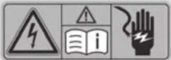
Warning symbol image showing hazard, warning sign, open book, and hand with lightning boltAll of the vehicle's high-voltage electrical system components are marked with yellow warning stickers which warn you of the dangers of high voltages. The cables of the vehicle's high-voltage electrical system are orange in color.
Observe the following before carrying out a general work such as changing a bulb or checking the coolant level:
• the ignition is switched off
- the charging cable for charging the high-voltage battery is disconnected
High-voltage electrical system
Danger of electric shock

DANGER
The vehicle's high-voltage electrical system is under high voltage. If you modify components in the vehicle's high-voltage electrical system or touch damaged components, you may be electrocuted. The components in the vehicle's high-voltage
Automatically switching off the vehicle's high-voltage electrical system
In order to prevent anyone coming into contact with high voltage, the high-voltage electrical system is generally switched off automatically in the following cases:
- the restraint systems are activated in the event of an accident
- an electrical short circuit is detected in the vehicle's high-voltage electrical system
- an electrical connection in the vehicle's high-voltage electrical system is disconnected
High-voltage battery

WARNING
In the event of a vehicle fire, the internal pressure of the high-voltage battery can exceed a critical value. In this case flammable gas escapes through a ventilation valve on the underbody. The gas can ignite. There is a risk of injury.
Leave the danger zone immediately. Secure the danger area at a suitable distance, whilst observing legal requirements.

WARNING
If the housing of the high-voltage battery has been damaged, electrolyte and gases may leak out. These are poisonous and caustic. There is a risk of injury.
Avoid contact with skin, eyes or clothing. Immediately rinse electrolyte splashes off with water and seek medical attention straight away.
Correct use
If warning stickers are removed, you may fail to recognize certain dangers. Leave warning stickers in place.
The following are important sources of information in regard to vehicle use:
- safety notes in this Operator's Manual
- technical data in this Operator's Manual
- traffic rules and regulations
- laws and safety standards pertaining to motor vehicles
Problems with your vehicle
If you should experience a problem with your vehicle, particularly one that you believe may affect its safe operation, we urge you immediately contact an authorized smart center to have the problem diagnosed and corrected if required. Do not drive the vehicle if you believe it may not be safely operated the matter is not handled to your satisfaction, please discuss the problem with the
smart center management, or if necessary contact us at one of the following addresses:
In the USA
Customer Relations Department
98 Vanderhoof Avenue
Mercedes-Benz Canada, Inc.
Toronto, Ontario M4G 4C9
QR codes for rescue card
QR codes are on the socket flap and on the door pillar (B-pillar) on the opposite side. In the event of an accident, rescue services can use the QR code to quickly determine the corresponding rescue card for a vehicle. The current rescue card contains the most important information about the vehicle in compact form, such as the routing of the electric cables. Further information: www.mercedes-benz.de/qr-code
Data stored in the vehicle
Information from electronic control units
Your vehicle is equipped with electronic control units. Some of them are necessary for your vehicle to function safely, some provide support when driving (driver assistance systems). In addition, your vehicle offers comfort or entertainment functions which are also made possible with electronic control units.
Electronic control units contain data memories which can permanently or temporarily store technical information on vehicle condition, component stress, service requirements as well as technical incidents and to malfunctions.
This information generally documents the This includes, for example:
condition of a component, a module, a system or the surroundings, for example:
- operating states of system components (e.g. fluid levels, battery status, tire pressure)
- status messages of the vehicle or its individual components (e.g. wheel revolutions/speed, deceleration in movement, lateral acceleration, display of seat belts fastened)
- malfunctions and defects in key system components (e.g. the lights and brakes)
• information on incidents in which the vehicle is damaged
- reactions of the systems in specific driving situations (e.g. deployment of an air bag, use of stability control systems)
- ambient conditions (e.g. temperature, rainzation in the vehicle and change them at any sensor) time.
• multimedia data, such as music, films or photos for playback in an integrated multimedia system
- address book data for use in an integrated hands-free system or an integrated navigation system
- navigation destinations entered
• data on the use of Internet services
This data can be saved locally in the vehicle or it is located on a device which you have connected to the vehicle. As long as this data is saved in the vehicle, you can delete it at any time. Transfer of this data to third parties only occurs at your request, especially
as part of online services according to the settings you have selected.
You can save comfort settings/individuali-
ization in the vehicle and change them at any time.
In addition to the provision of control unit Depending on the equipment, these include, functions, this data serves to detect and refer example:
tify malfunctions as well as to optimize vehicle functions by the manufacturer. Most of this data is volatile and is only processed in
the vehicle itself. Only a small proportion of the data is stored in event or error memories
When service work is done on your vehicle, the technical data from the vehicle can be read out by service network staff or third parties. Service work is, for example, repair work, maintenance, warranty claims and
quality assurance measures. The data is read out using the legally prescribed OBD (European On-board Diagnostics) connector in the vehicle. The respective workshop of service
- settings of the seat and steering wheel positions
of chassis and climate control settings es individualization such as interior lighting
As long as your vehicle is suitably equipped, you can connect your mobile phone or another mobile end device with the vehicle. You can operate these devices via the control elements integrated in the vehicle. Images
and sound from the mobile phone can played back via the multimedia system. At the same time, certain information is transferred to your mobile phone.
network or third parties collect, process and this includes, depending on the type of inte-use the data. The data documents technical gration, for example:
states of the vehicle, help in finding errors and in improving quality and are transferred to the manufacturer if necessary. In addition
the manufacturer is subject to product liability. For this purpose, the manufacturer requires technical data from vehicles.
Malfunction memories in the vehicle can be reset by a service outlet during repairs or service work.
Depending on the equipment selected, you can enter data in comfort and infotainment functions of the vehicle.
• general vehicle information • position data
This allows the use of selected mobile phone apps, e.g. navigation or music playback.
There is no further interaction between mobile phone and vehicle; in particular there is no active access to vehiclata. How data is further processed is determined by the provider of the specific app used. Which settings you can make, if any, depends on the specific app and the operating system of your mobile phone.
Service providers
Wireless network connection
In as far as your vehicle has a wireless network connection, this will permit the exchange of data between your vehicle and further systems. The wireless network connection is enabled by a transmission and reception device installed in the vehicle or via mobile end devices (e.g. mobile phones) you bring into the vehicle. Online functions can be used via this wireless network connection. These include online services and applications/apps, which are provided by the manufacturer or by other providers.
Manufacturer's own services
For online services of the manufacturer, the manufacturer describes the specific functions and the associated data protection information in an appropriate place. Personal identification data may be used to provide online services. Data transfer to this end occurs via a protected connection e.g. using the IT systems of the manufacturer provided for this purpose. The collecting, processing, and use of personal identification data beyond the provision of services occurs exclusively on the basis of a legal permit or after due consent.
Generally, you can enable or disable the services and functions (which sometimes have associated costs). In some cases, this also applies to the whole data connection of the vehicle. Excluded from this are special legally prescribed functions and services.
Services of third parties
In as far as it is possible to use the online services of other providers, these services are subject to the responsibility as well as the data protection and terms of use of the respective provider. The manufacturer has no influence on the contents exchanged whilst using these services.
Please ask the respective service provider for details on the type, extent and purpose of the collection and use of personal data in the context of third party services.
Information on copyright
Information on licenses of Free and Open-Source software used in the vehicle and the electronic components: http://www.mercedes-benz.com/opensource
Dashboard
text_image
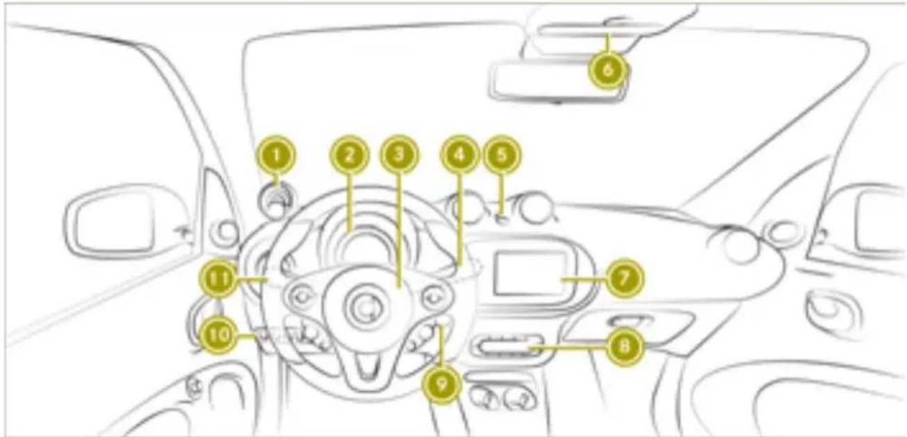
Diagram of a car interior with numbered component labels pointing to key parts such as dashboard, steering wheel, and dashboard controls.| Function Page | ||
| 1 | Charge level display 57Power display 57 | |
| 2 | Instrument cluster 32 | |
| 3 | Horn | |
| 4 | Windshield wipers combination switch | 71 |
| 5 | Automatic locking feature 73Hazard warning lamps 154 | |
| 6 | Overhead control panel 30 | |
| 7 | smart Audio-System 89smart Media-System 96 |
| Function Page | ||
| 8 | Climate control system control panel | 78 |
| 9 | Ignition lock 52 | |
| 10 | Control panel for:Tailgate releaseForward collision warning Acoustic presence indicator | 4555 |
| 11 | Lights combination switch | 69 |
Multifunction steering wheel
text_image
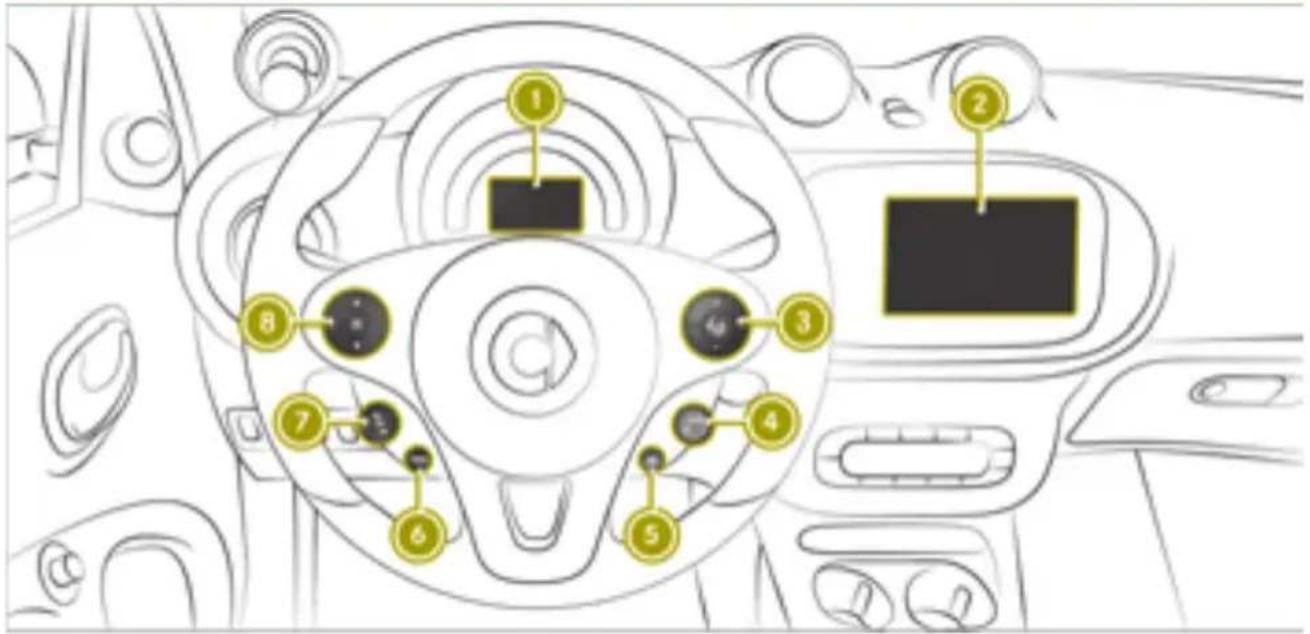
Diagram of a car dashboard with numbered component labels pointing to key areas such as the steering wheel, dashboard, and camera.| Function Page | ||
| 1 | Color display of the instrument cluster | 85 |
| 2 | smart Audio-System 89smart Media-System 96 | |
| 3 | + - Adjusts the volumeSwitches voice-operated control on or off and accepts or ends a call | 9696 |
| 4 | SET + Increases or stores the current speed- Decreases current speed 61 | 61 |
| 5 | RES Calls up the last speed stored | 61 |
| Function Page | ||
| 6 | CANCEL Interrupts cruise control | 61 |
| 7 | Cruise control buttonON Activates cruise con-trolOFF Deactivates cruise control | 6161 |
| 8 | ▲▼ Scrolls through menusOK Confirms the selec-tion | 8587 |
Center console with drawer
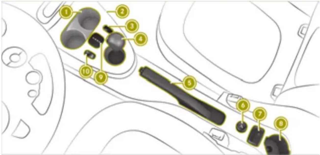
text_image
Diagram of a car interior with numbered components for identification and assembly reference.| Function Page | ||
| 1 | Cup holder 121Ashtray 81 | |
| 2 | Drawer 121 | |
| 3 | smart fortwo coupe: coin holder | |
| 3 | smart fortwo cabrio: opens and closes the soft top | 75 |
| 4 | Selector lever 55 | |
| 5 | Parking brake 53 |
| Function Page | ||
| 6 | Cigarette lighter 81Socket 82 | |
| 7 | smart Media-System: AUX port, USB port and SD card slot | 96 |
| 8 | Cup holder 121 | |
| 9 | Selector lever indicator 54 | |
| 10 | ECO mode 56 |
Overhead control panel

text_image
Diagram showing car interior components with numbered labels pointing to a vehicle's seat area| Function Page | |
| 1 | Left-hand reading lamp 70 |
| 2 | Interior lighting 70 |
| 3 | Right-hand reading lamp 70 |
| Function Page | ||
| 4 | PASSENGER AIRBAG indicator lamps | 39 |
| 5 | Rear-view mirror 50 |
Door control panel
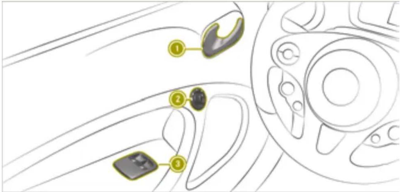
text_image
Diagram of a car interior showing labeled parts with numbered annotations| Function Page | ||
| 1 | Opens the door 73 | |
| 2 | Adjusts the exterior mirrors | 51 |
| Function Page | ||
| 3 | Opens and closes the side windows | 74 |
Displays shown in the instrument cluster and the display
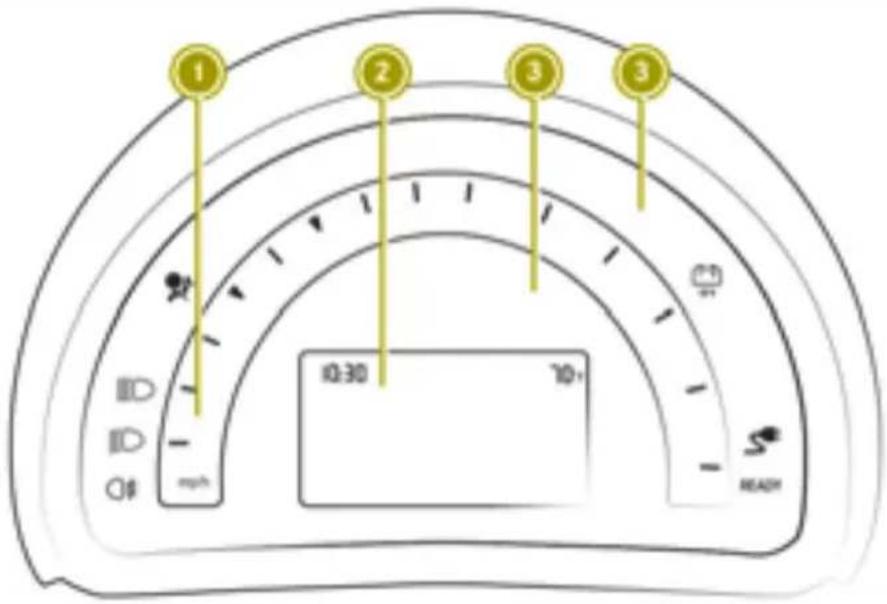
text_image
1 2 3 3 10:30 70+ ## READ| Function Page | ||
| 1 | Speedometer | |
| 2 | Display | |
| 3 | Warning and indicator lamps | |
| Doors or tailgate 167 | ||
| Seat belts 168 | ||
| Restraint system 169 | ||
| Drive diagnostics 172 | ||
| BRAKE | USA: brakes 171 | |
| (1) | Canada: brakes 171 | |
| ABS | USA: ABS 175 | |
| Canada: ABS 175 | ||
| ESP® | 46 | |
| Tire pressure monitor 177 |
| Function Page | ||
| Distance warning signal 180 | ||
| Forward collision warning 180 | ||
| 12 V battery 181 | ||
| Rear fog lamp 70 | ||
| Front fog lamps 70 | ||
| High-beam headlamps 69 | ||
| Low-beam headlamps | 69 | |
| Parking lamps | 70 | |
| Charging cable | 172 | |
| Cruise control | 181 | |
| Next service due date | ||
| 172 | ||
| READY | READY indicator | 181 |
Activating and deactivating the panic alarm
side. The risk of injuries due to a deployed air bag also cannot be completely eliminated.
▶ To activate: press the PANIC button on the SmartKey for about two seconds.
An alarm sounds and the exterior lighting flashes.
▶ To deactivate: press the PANIC button on SmartKey.
Occupant safety
Restraint system
Protection provided by the restraint system
The restraint system includes the:
- Seat belt system
- Air bags
In an accident the restraint system can:
- reduce the risk of vehicle occupants com-vehicle by smart.
ing into contact with parts of the vehicleContact a smart center for details. USA only: interior contact our Customer Assistance Center on - reduce the forces to which vehicle occu- 1-800-762-7887 for more details. pants are subjected
-vehicle by smart.
Contact a smart center for details. USA only: contact our Customer Assistance Center on 1-800-762-7887 for more details.
A seat belt can only provide maximum protection when worn correctly. Depending on the type of accident detected, Emergency
-Preparing the restraint system for operation
Tensioning Devices and/or air bags may supplement a correctly worn seat belt. Not even accident will trigger the Emergency Tensioning Devices and/or deploy the air bags. To ensure that the restraint system provides the maximum protection, every vehicle occu
pant must:
• have the seat belt fastened correctly
- sit in a position that is as upright as possible with the back against the seat back-rest
• have their feet resting on the floor, if possible
- always be secured in special additional restraint systems suitable for your vehicle if under 5 ft (1.50 m) tall
However, no system available today can completely eliminate injuries and fatalities
in every accident. In particular, the seat belt and air bag generally do not protect against objects penetrating the vehicle from the out-
Restraint system malfunctions
s- When the ignition is switched on, the restraint system warning lamp does not light up.
While driving, the restraint system warning lamp remains lit or lights up repeatedly.
s- When the ignition is switched on, the restraint system warning lamp does not light up.
While driving, the restraint system warning lamp remains lit or lights up repeatedly.
If the restraint system is malfunctioning, the vehicle's high-voltage electrical system may also not be deactivated as intended in the event of an accident.
WARNING
Modifications to the restraint system may cause it to no longer work as intended. The restraint system may then not perform its intended protective function and may fail in an accident or trigger unexpectedly, for example. This poses an increased risk of injury or even fatal injury.
Never modify parts of the restraint system. Never tamper with the wiring, the electronic components or their software.
If the vehicle needs to be adjusted to accommodate a person with disabilities, contact a qualified specialist workshop. smart recommends that you only use driving assistance systems which have been approved for your
When the ignition is switched on, the restraint system warning lamp lights up during the system self-test. It goes out no later than a few seconds after the vehicle is started. The components of the restraint system are then ready for operation.
When the ignition is switched on, the restraint system warning lamp lights up during the system self-test. It goes out no later than a few seconds after the vehicle is started. The components of the restraint system are then ready for operation.
When the ignition is switched on, the restraint system warning lamp lights up during the system self-test. It goes out no later than a few seconds after the vehicle is started. The components of the restraint system are then ready for operation.
Restraint system malfunctions
If the restraint system is malfunctioning, the vehicle's high-voltage electrical system may also not be deactivated as intended in the event of an accident.
If the restraint system is malfunctioning, the vehicle's high-voltage electrical system may also not be deactivated as intended in the event of an accident.

DANGER
If the restraint system is malfunctioning, restraint system components may be triggered unintentionally or may not deploy as intended during an accident. This can affect for example the Emergency Tensioning Device or the air bag. Furthermore, in the event of an accident, the vehicle's high-voltage electrical system may not be deactivated as intended. You may be electrocuted if you touch the damaged components of the vehicle's high-voltage electrical system. This poses an increased risk of injury or even fatal injury.
Have the restraint system checked and repaired in a qualified specialist workshop as soon as possible. After an accident, switch off the ignition immediately and remove the key from the ignition lock.
Restraint system response during an accident
vehicle deceleration is not high. Conversely, an air bag may be deployed even though the vehicle suffers only minor deformation. If, for instance, very rigid vehicle parts such as longitudinal body members are hit, the rate of vehicle deceleration may be sufficient.
The restraint system components can be activated or triggered independently of each other:
| Component Detected trigger situation | |
| Emergency Tensioning Device (ETD) for seat belts | Head-on collision, rear impact, side impact, rollover |
| Driver's air bag, front-passenger front air bag and knee bag | Head-on collision |
| Side impact air bag | Side impact |
| Windowbag1 or headbag2 | Side impact, roll-over, head-on collision |
The way the restraint system responds depends on the severity of the impact detected and the apparent type of accident:
- Head-on collision
- Rear impact
- Side impact
- Rollover
The activation threshold for the restraint system components is determined based on the analysis of the sensor values measured various points in the vehicle. This process is pre-emptive in nature. The triggering process of the restraint system components should take place in good time at the start of the collision.
Factors which can only be seen and measured after a collision has occurred do not play a decisive role in the deployment of an air bag, nor do they provide an indication of air bag deployment.
The vehicle may be deformed significantly without an air bag being deployed. This is the case if only parts which are relatively easily deformed are affected and the rate of
The front-passenger front air bag can only be deployed in an accident if the PASSENGER AIR BAG ON indicator lamp is lit. If the front-passenger seat is occupied, make sure that the status of the front-passenger front air bag is correct both before and during the journey ( page 39).

WARNING
The air bag parts are hot after an air bag has been deployed. There is a risk of injury.
Do not touch the air bag parts. Have a deployed air bag replaced at a qualified specialist workshop as soon as possible.
i smart recommends that you have the vehicle towed to a qualified specialist workshop after an accident. Take this into of account, particularly if an Emergency Tensioning Device was triggered or an air bag was deployed.
If the Emergency Tensioning Devices are triggered or an air bag is deployed, you will hear a bang, and a small amount of powder may also be released:
- The bang will not usually affect your hearing.
- In general, the powder released is not hazardous to health but may cause short-term breathing difficulties to persons suffering from asthma or other pulmonary conditions.
Provided it is safe to do so, leave the vehicle immediately or open the window in order to prevent breathing difficulties.
Air bags and pyrotechnic Emergency Tensioning Devices contain perchlorate material, which may require special handling and environmental protection measures.
National guidelines must be observed during disposal. In California, see www.dtsc.ca.gov/HazardousWaste/Perchlorate/index.cfm.
Seat belts
Protection provided by seat belts
Always fasten seat belts correctly before starting your journey. A seat belt can only provide maximum protection when worn correctly.

WARNING
If the seat belt is not worn correctly, it cannot perform its intended protective function. An incorrectly fastened seat belt can also cause injuries, for example, in the(▷ page 42).
event of an accident or when braking or changing direction abruptly. This poses a increased risk of injury or even fatal injury.
Always ensure that all vehicle occupants have their seat belts fastened correctly and are sitting properly.
• The seat belt must:
- not be twisted and must be tight and fit snugly across your body
- be routed across the center of the shoulder and as low down across your hips as possible
The shoulder section of the seat belt should not touch your neck nor be routed under your arm or behind your back.
- Avoid wearing bulky clothing, e.g. a winter coat.
-
Press the lap belt down into your hip joints and pull tight by the shoulder section of the belt. The lap belt must never be routed across your stomach or abdomen.
-
Never route the seat belt across sharp, pointed, abrasive or fragile objects.
- Only one person per seat belt. Infants and children must never travel sitting on the lap of a vehicle occupant.
- Never secure objects with a seat belt if the seat belt is also being used by one of the vehicle's occupants. Always observe the notes on "Loading the vehicle" for securing objects, luggage or loads▶(page 122).
Also make sure that objects are never placed between an occupant and the seat, e.g. a cushion.
The front-passenger seat belt is equipped with a special seatbelt retractor. Further information can be found under "Special seatbelt retractor" ( page 43).
If children are traveling in the vehicle, be sure to observe the instructions and safety notes on "Children in the vehicle"
e(▷ page 42).
_1 Limited protection from seat belts

WARNING
The seat belt does not offer the intended level of protection if you have not moved the backrest to an almost vertical position. When braking or in the event of an accident, you could slide underneath the seat belt and sustain abdomen or neck injuries, for example. This poses an increased risk of injury or even fatal injury.
Adjust the seat properly before beginning your journey. Always ensure that the
backrest is in an almost vertical position and that the shoulder section of your seat belt is routed across the center of your shoulder.

WARNING
Persons less than 5 ft (1.50 m) tall cannot wear the seat belt correctly without an additional and suitable restraint system. If the seat belt is not worn correctly, it cannot perform its intended protective function. An incorrectly fastened seat belt can also cause injuries, for example, in the event of an accident or when braking or changing direction abruptly. This poses an increased risk of injury or even fatal injury.
For this reason, always secure persons under 5 ft (1.50 m) tall in suitable additional restraint systems.

WARNING
If objects between the seat and door are blocking the moving belt anchorage on the seat, this restricts the restraining effect of the seat belt. The seat belt can no longer protect as intended. This poses an increased risk of injury or even fatal injury.
Make sure that no objects are between the seat and door before beginning a journey.

WARNING
The seat belts may not perform their intended protective function if:
- they are damaged, modified, extremely dirty, bleached or dyed
- the seat belt buckle is damaged or extremely dirty
- the Emergency Tensioning Devices, belt anchorages or inertia reels have been modified.
Seat belts may be damaged in an accident, although the damage may not be visible, e.g. due to splinters of glass. Modified or damaged seat belts may tear or fail, e.g. in an accident. Modified Emergency Tensioning Devices could accidentally trigger or fail to deploy when necessary. This poses an increased risk of injury or even fatal injury.
Never modify the seat belts, Emergency Tensioning Devices, belt anchorages and inertia reels. Make sure that the seat belts are undamaged, not worn out and clean. Following an accident, have the seat belts checked immediately at a qualified specialist workshop.
Only use seat belts which have been approved specifically for your vehicle by smart.

WARNING
Emergency Tensioning Devices that have deployed pyrotechnically are no longer operational and are unable to perform their intended protective function. This poses an increased risk of injury or even fatal injury.
Have pyrotechnically triggered Emergency Tensioning Devices replaced immediately at a qualified specialist workshop.
smart recommends that you have the vehicle towed to a qualified specialist workshop after an accident.
! Make sure that the seat belt is fully rolled up. Otherwise, the seat belt or belt tongue will be trapped in the door or in the seat mechanism. This could damage the door, - the door trim panel and the seat belt. Damaged seat belts can no longer fulfill their protective function and must be replaced. Visit a qualified specialist workshop.
Fastening and releasing the seat belt
If the seat belt is pulled out quickly or sharply, the inertia reel locks. The belt strap cannot be pulled out any further.
! If the front-passenger seat is not occupied, do not engage the seat belt tongue in the buckle on the front-passenger seat. Otherwise, in addition to other systems, the Emergency Tensioning Device could
also be triggered in the event of an accident and would need to be replaced.
For easy fastening, the seat belt is guided through the seat belt guide on the side of seat.

text_image
Diagram showing a person using a belt switch to adjust the seat, with labeled parts 1 and 2 indicating different components.① Buckle
② Seat belt tongue
▶ To fasten: always engage seat belt tongue ② into buckle ① of the corresponding seat.
▶ To release: press the release button in belt buckle ① and guide the seat belt back by belt tongue ②.
Belt warning for the driver and front-passenger
The ☐ seat belt warning lamp in the instrument display is a reminder that all vehicle occupants must wear their seat belts correctly.
After each start, the ☐ seat belt warning lamp flashes for six seconds.
In addition, there may be a warning tone. The belt warning goes out as soon as the doors are closed and the driver and front-passenger fasten their seat belts.
The belt warning comes on:
Air bags
Overview of air bags
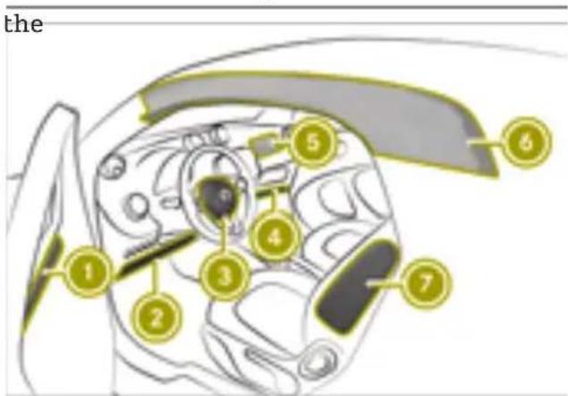
text_image
the 1 2 3 4 5 6 7The installation location of an air bag is identified by the AIRBAG symbol.
A deployed air bag can increase the level of protection provided to the vehicle occupant.
| Air bag Possible protection for: | ||
| t 1 | Headbag3 | Head |
| y 2 | Driver's knee bag | Thigh, knee and lowe leg |
| 3 | Driver's air bag | Head and thorax |
| 4 | Front-passenger knee bag | Thigh, knee and lowe leg |
| s 5 | Front-passenger front air bag | Head and thorax |
| g 6 | Windowbag4 | Head |
| 7 | Side impact air bag | Thorax and pelvis |
- if the vehicle exceeds a speed of 12 mph The front-passenger front air bag can only (20 km/h) once and neither the driver nor be deployed in an accident if the PASSENGER the front passenger have fastened their seat belt AIR BAG ON indicator lamp is lit. If the front-passenger seat is occupied, make sure that the status of the front-passenger front air bag is correct both before and during the journey ( page 39).
Protection provided by the air bags
Depending on the type of accident, an air can supplement a correctly worn seat belt and provide added protection.

WARNING
If you do not sit in the correct seat position the air bag cannot protect as intended and could even cause additional injury when deployed. This poses an increased risk of injury or even fatal injury.
To avoid hazardous situations, always make sure that all of the vehicle's occupants:
• have fastened their seat belts correctly, including pregnant women
- are sitting correctly and maintain the greatest possible distance to the air bags
• follow the following instructions
Always make sure that there are no objects between the air bag and the vehicle's occupants.
To avoid risks as a result of a deployed air bag:
- Adjust seats correctly before starting your journey and move the driver's and front-passenger seat as far back as possible. Always observe the information on the correct driver's seat position>(page 48).
- Only hold onto the outside of the steering wheel rim. This allows the air bag to be fully deployed.
• Always lean against the backrest while driving. Do not lean forwards or lean against the door or side window. You may otherwise be in the deployment area of the air bags.
- Always keep your feet on the floor. Do not put your feet on the dashboard, for example. Your feet may otherwise be in the deployment area of the air bag.
- When children are traveling in the vehicle follow the related additional notes (▷ page 42).
• Always properly stow and secure objects.
Objects in the vehicle interior may limit an air bag's ability to function correctly. Therefore, always make sure that:
- There are no people, animals or objects between the vehicle occupants and an air-bag.
There are no objects between the seat, the door and the door pillar (B-pillar). - No hard objects, e.g. coat hangers, are hanging on the grab handles or coat hooks.
- No accessories, such as cup holders, are attached within the deployment area of an airbag, e.g. to doors, side windows or side trim panels.
- No heavy, sharp-edged or fragile objects are kept in the pockets of clothing. Store such objects in a suitable place.
Limited protection from air bags

WARNING
If you modify the air bag cover or affix objects such as stickers to it, the air bag can no longer function correctly. There is an increased risk of injury.
Never modify an air bag cover or affix objects to it.

WARNING
Unsuitable seat covers can obstruct or even prevent the deployment of the air bags integrated in the seats. Consequently, the air bags cannot protect vehicle occupants as intended. In addition, the operation of the automatic front-passenger front air bag deactivation system could be restricted. This poses an increased risk of injury or even fatal injury.
Only use seat covers that have been approved for the corresponding seats by smart.

WARNING
Sensors to control the air bags are located in the doors. Modifications or work not performed correctly to the doors or door paneling, as well as damaged doors, can lead to
the function of the sensors being impaired. The air bags might therefore not function properly anymore. Consequently, the air bags cannot protect vehicle occupants as they are designed to do. There is an increased risk of injury.
Never modify the doors or parts of the doors. Always have work on the doors or door paneling carried out at a qualified specialist workshop.

WARNING
A deployed air bag no longer offers any protection and cannot provide the intended protection in an accident. There is an increased risk of injury.
Have the vehicle towed to a qualified specialist workshop in order to have a deployed air bag replaced.
Have deployed air bags replaced immediately.
Status of the front-passenger front air bag
Important notes when the front-passenger seat is occupied
- the back of a forward-facing child restraint system must lie as flat as possible against the front-passenger backrest - the child restraint system must not touch the roof. Adjust the angle of the seat back-rest accordingly

WARNING
Objects between the seat surface and the child restraint system could affect the function of the automatic front-passenger front air bag deactivation system. This could result in the front-passenger air bag not functioning as intended during an accident. This poses an increased risk of injury or even fatal injury.
Do not place any objects between the seat surface and the child restraint system. The entire base of the child restraint system must always rest on the seat cushion of the front-passenger seat. The backrest of the forwardfacing child restraint system must, as far as possible, be resting on the backrest of the front-passenger seat.
Always comply with the child restraint system manufacturer's installation instructions.
A person on the front-passenger seat must:
The automatic front-passenger air bag deactivation system can detect if there is a person or a child restraint system on the front-passenger seat. The front-passenger air bag is enabled or disabled accordingly.
When installing a child restraint system on the front-passenger seat:
- ensure that the child restraint system is positioned correctly (page 42)
- always comply with the child restraint system manufacturer's installation instructions
- never place objects, such as cushions, under or behind the child restraint system
- the base of the child restraint system must lie fully against the seat cushion of the front-passenger seat
• have the seat belt fastened correctly
• sit in a position that is as upright as possible with the back against the seat back-rest
• have their feet resting on the floor, if possible
Otherwise the front-passenger air bag can be disabled by mistake, for instance because the front-passenger:
- has transferred their weight by leaning on the armrests in the vehicle
- sits in such a way that the weight on the seat cushion is reduced

WARNING
If the PASSENGER AIR BAG OFF indicator lamp is lit, the front-passenger front air bag is disabled. It will not be deployed in the event of an accident and cannot perform its intended protective function. A
person in the front-passenger seat could then, for example, come into contact with the vehicle's interior, especially if the person is sitting too close to the dashboard. This poses an increased risk of injury or even fatal injury.
When the front-passenger seat is occupied, always ensure that:
- the classification of the person in the front-passenger seat is correct and the front-passenger front air bag is enabled or disabled in accordance with the person in the front-passenger seat
- the front-passenger seat has been moved back as far back as possible.
- the person is seated correctly.
Make sure, both before and during the journey, that the status of the front-passenger front air bag is correct.
PASSENGER AIR BAG indicator lamps System self-test
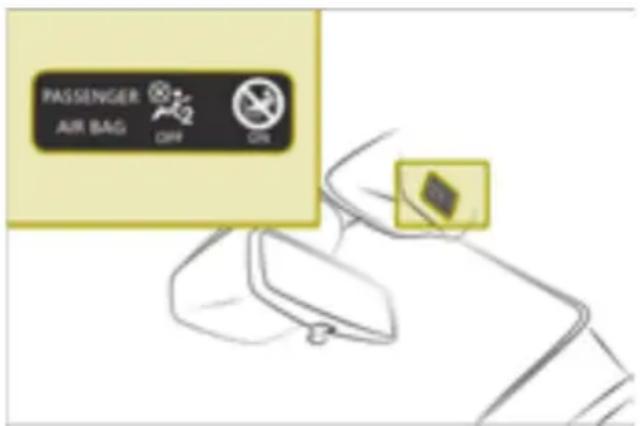
text_image
PASSenger AIR BAG Off OffWhen the ignition is switched on, both PASSENGER AIR BAG ON and OFF indicator lamps light up at the same time during the system self-test.
The indicator lamps then display the status of the front-passenger front air bag:
- PASSENGER AIR BAG ON lights up: the front-passenger front air bag is enabled. If, in the case of an accident, all deployment criteria are met, the front-passenger front air bag is deployed.
- PASSENGER AIR BAG OFF lights up: the front-passenger front air bag is disabled.
It will then not be deployed in the event of an accident.
If the PASSENGER AIR BAG OFF indicator lamp and restraint system warning lamp light up at the same time, the front-passenger seat may not be used. In this case, do not install a child restraint system on the front-passenger seat. Have the automatic front-passenger air bag deactivation system checked and repaired immediately at a qualified specialist workshop.
Status indicator
If the front-passenger seat is occupied, make sure that the status of the front-passenger front air bag is correct for the prevailing conditions both before and during the journey.
After installing a rearward-facing child restraint system on the front-passenger seat:
PASSENGER AIR BAG OFF must be lit continuously.

WARNING
If you secure a child in a rearward-facing child restraint system on the front-passenger seat and the PASSENGER AIR BAG ON indicator lamp is lit up, the front-passenger front air bag may deploy in an accident. The child could be struck by the air bag. This poses an increased risk of injury or even fatal injury.
Make sure that the front-passenger front air bag has been deactivated. The PASSENGER AIR BAG OFF indicator lamp must be lit.
NEVER use a rearward-facing child restraint on a seat protected by an ACTIVE FRONT AIR BAG in front of it; DEATH or SERIOUS INJURY to the child can occur.
Observe the vehicle-specific notes when installing a child restraint system on the front-passenger seat ( page 42). The PASSENGER AIR BAG ON indicator lamp may light up, depending on the child restraint system and the size of the child. In this case, do not install the rearward-facing
child restraint system on the front-passenger seat.
After installing a forward-facing child restraint system on the front-passenger seat:
PASSENGER AIR BAG OFF or PASSENGER AIR BAG ON may be lit continuously, depending on the child restraint system and the child's stature. Always observe the following notes:

WARNING
If you secure a child in a forward-facing child restraint system on the front-passenger seat and you position the front-passenger seat too close to the dashboard, in the event of an accident, the child could:
- come into contact with the vehicle's interior if the PASSENGER AIR BAG OFF indicator lamp is lit, for example
- be struck by the air bag if the PASSENGER AIR BAG ON is lit up
This poses an increased risk of injury or even fatal injury.
Move the front-passenger seat as far back as possible. Always make sure that the shoulder belt strap is correctly routed from the vehicle belt guide to the shoulder belt guide on the child restraint system. The shoulder belt strap must be routed forwards and downwards from the belt guide. Always observe the child restraint system manufacturer's installation instructions.
Observe the vehicle-specific notes when installing a child restraint system on the front-passenger seat ( page 42).
If a person is sitting on the front-passenger seat:
PASSENGER AIR BAG OFF or PASSENGER AIR BAG ON may be lit continuously, depending on the person's stature. Always observe the following notes:
If the front-passenger seat is occupied by:
- an adult or a person of corresponding stature, the PASSENGER AIR BAG ON indicator lamp must be lit continuously. This indicates that the front-passenger air bag is enabled
If the PASSENGER AIR BAG OFF lights up continuously, the front-passenger seat must not be used by an adult or person corresponding stature.
- a person of smaller stature (e.g. a teenage or small adult), either the PASSENGER AIR BAG OFF or PASSENGER AIR BAG ON lamp lights up continuously, depending on the Occupant Classification System result
- PASSENGER AIRBAG ON is lit continuously: move the front-passenger seat as far back as possible
- PASSENGER AIRBAG OFF is lit continuously: the front-passenger seat must not be used by a person of small stature

WARNING
If the PASSENGER AIRBAG OFF indicator lamp remains lit after the system self-test, the front-passenger front air bag is disabled. It will not be deployed in the event of an accident. In this case, the front-passenger front air bag cannot perform its intended protective function, e.g. when a person is seated in the front-passenger seat.
That person could, for example, come into contact with parts of the vehicle's interior, especially if the person is sitting too close to the dashboard. This poses an increased risk of injury or even fatal injury.
When the front-passenger seat is occupied, always ensure that:
- the classification of the person in the front-passenger seat is correct and the front-passenger front air bag is enabled or disabled in accordance with the person in the front-passenger seat
- the person is seated properly with a correctly fastened seat belt
- the front-passenger seat has been moved as far back as possible
If children are traveling in the vehicle, be The use of seat belts and child restraint sy-sure to observe the notes on "Children in thems is required by law in:
vehicle" (▷ page 42).
Children in the vehicle
Traveling safely with children on board

WARNING
If you leave children unsupervised in the vehicle, they could set it in motion by, for example:
- release the parking brake.
- shift the automatic transmission out of the parking position P.
- start the engine.
In addition, they may operate vehicle equipment and become trapped. There is a risk of an accident and injury.
When leaving the vehicle, always take the SmartKey with you and lock the vehicle. Never leave children unsupervised in the vehicle.

WARNING
If persons, particularly children are subjected to prolonged exposure to extreme heat or cold, there is a risk of injury, possibly even fatal. Never leave children unattended in the vehicle.

WARNING
If the child restraint system is subjected direct sunlight, parts may get very hot. Children may burn themselves on these parts, particularly on the metal parts of child restraint system. There is a risk of injury.
If you leave the vehicle, taking the child with you, always ensure that the child restraint system is not exposed to direct sunlight. Protect it with a blanket, for example. If the child restraint system has been exposed to direct sunlight, let it cool down before securing the child in it. Never leave children unattended in the vehicle.
- all 50 states
• the U.S. territories
• the District of Columbia
• all Canadian provinces
All child restraint systems must meet the following standards:
• U.S. Federal Motor Vehicle Safety Standards 213 and 225
- Canadian Motor Vehicle Safety Standards 213 and 210.2
You can obtain further information about the correct child restraint system from any smart center.
To provide better protection to children younger than twelve years old and under 5 ft (1.50 m) tall, smart recommends always observing the following:
- Secure children only in a child restraint system that is appropriate for the age, weight and size of the child and that is recommended and suitable for use in smart vehicles. Make sure you observe the instructions for correct use of the child restraint system.
- Only use the following securing systems with the child restraint systems:
- the seat belt system
- the Top Tether anchorages
- The manufacturer's child restraint system installation instructions.
- The warning labels in the vehicle interior and on the child restraint system.
to ⚠️ WARNING
If the child restraint system is installed incorrectly on a suitable seat, it cannot the protect as intended. The child cannot then be restrained in the event of an accident, heavy braking or sudden changes of direction. There is an increased risk of injury, possibly even fatal.
Make sure that you observe the child restraint system manufacturer's installation instructions and the notes on use.
Please ensure, that the base of the child restraint system is always resting completely on the seat cushion. Never place
objects, e.g. cushions, under or behind the child restraint system. Only use child restraint systems with the original cover designed for them. Only replace damaged covers with genuine covers.

WARNING
If the child restraint system is installed incorrectly or is not secured, it can come loose in the event of an accident, heavy braking or a sudden change in direction. The child restraint system could be thrown about, striking vehicle occupants. There is an increased risk of injury, possibly even fatal.
Always install child restraint systems properly, even if they are not being used. Make sure that you observe the child restraint system manufacturer's installation instructions.

WARNING
Child restraint systems or their securing systems which have been damaged or subjected to a load in an accident can no long protect as intended. The child cannot then be restrained in the event of an accident, heavy braking or sudden changes of direction. There is an increased risk of injury, possibly even fatal.
Replace child restraint systems which have been damaged or subjected to a load in an accident as soon as possible. Have the securing systems on the child restraint system checked at a qualified specialist workshop, before you install a child restraint system again.
notes on child restraint systems on the front-passenger seat (page 44).
- Notes on seat belts (▷ page 35).
Activating/deactivating the special seatbelt retractor of the seat belt

WARNING
If the seat belt is released while driving, the child restraint system will no longer be secured properly. The special seat belt retractor is disabled and the inertia real draws in a portion of the seat belt. The seat belt cannot be immediately refastened. There is an increased risk of injury, possibly even fatal.
Stop the vehicle immediately, paying attention to road and traffic conditions. Reactivate the special seat belt retractor and secure the child restraint system properly.
When activated, the special seat belt retractor ensures that the seat belt on the front-passenger seat does not slacken once the child restraint system is secured.
Always comply with the child restraint system manufacturer's installation instructions when installing and removing the child restraint system.
Activating the special seat belt retractor:
▶ Pull the seat belt out fully and let the seat belt retractor retract it again.
When the special seat belt retractor is activated, you should hear a ratcheting sound.
▶ Push the child seat restraint system down until the seat belt is tight.
Deactivating the special seat belt retractor:
A booster seat may be necessary to achieve proper seat belt positioning for children over 41 lbs (18 kg) or until they reach a height where a three-point seat belt can be properly fastened without a booster seat.
Also, always observe the detailed information below:
- When installing a child restraint system on the front-passenger seat, observe the
Press the release button on the seat belt buckle.
Hold the belt tongue firmly and guide it back towards the belt loop.
Securing Top Tether
Top Tether can reduce the risk of injury, since it provides an additional connection
between the child restraint system and the vehicle.
The child restraint system must be equipped with a Top Tether belt.
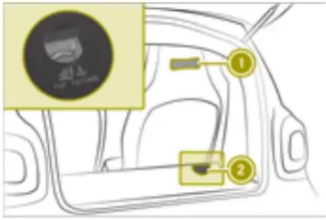
text_image
Diagram of a car interior with labeled parts and a circular icon showing a person wearing a T-1000-branded shirt.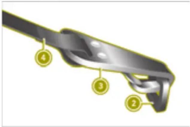
text_image
Technical diagram of a mechanical component with numbered parts labeled 2, 3, and 4Top Tether anchorage ② is mounted to the cargo compartment floor.
▶ Route Top Tether belt ④ back over the head restraint, keeping it as central as possible, into the cargo compartment through loop ①.
▶ Hook Top Tether hook ③ of Top Tether belt ④ into Top Tether anchorage ②. Lift up the carpet a little if necessary. Make sure that:
- Top Tether hook ③ is hooked into Top Tether anchorage ② as shown.
- Top Tether belt ④ is not twisted.
▶ Tension Top Tether belt ④. Always comply with the child restraint system manufacturer's installation instructions when doing so.
Child restraint systems on the front-passenger seat
Notes on child restraint systems
If you secure a child in a child restraint system on the front-passenger seat, always observe the information and safety notes on the automatic front-passenger front air bag deactivation system ( page 39).
You avoid risks resulting from:
- a child restraint system that is not detected by the automatic front-passenger front air bag deactivation system
- the unintentional deactivation of the front-passenger front air bag
- positioning the child restraint system incorrectly
Notes on rearward and forward facing child restraint systems
If you secure a child in a rearward-facing child restraint system on the front-passenger seat, always make sure that the front-passenger front air bag is deactivated. This is only the case if the PASSENGER AIR BAG OFF indicator lamp is permanently lit (▷ page 39).
When using child restraint systems on the front-passenger seat, always observe the following:
- Move the front-passenger seat as far back as possible.
- The base of the child restraint system must lie fully against the seat cushion of the front-passenger seat.
- The back of a forward-facing child restraint system must lie as flat as possible against the front-passenger backrest. The child restraint system must not touch the roof or be put under strain by the head restraint.
Adjust the angle of the seat backrest accordingly.
- Always make sure that the shoulder belt strap is correctly routed from the vehicle belt outlet to the shoulder belt guide on the child restraint system. The shoulder belt
strap must be routed forward and rearwamaintain a safe distance from the vehicle in from the vehicle belt outlet. front. Drive carefully.
- Never place objects, such as a cushion, under or behind the child restraint system. Always comply with the manufacturer's installation and operating instructions for the child restraint system used.
For safety reasons, smart recommends that you only use snow chains that have been specially approved for your vehicle by smart. Further information can be obtained at a smart center or a qualified specialist workshop.
Pets in the vehicle

WARNING
If you leave animals unattended or unsecured in the vehicle, they could press but tons or switches, for example.
As a result, they could:
- activate vehicle equipment and become trapped, for example
- activate or deactivate systems, thereby endangering other road users
Unsecured animals could also be flung around the vehicle in the event of an accident or sudden steering or braking, thereby injuring vehicle occupants. There is a risk of an accident and injury.
Never leave animals unattended in the vehicle. Always secure animals properly during the journey, e.g. use a suitable animal transport box.
Driving safely
Driving safety system limitations
! Make sure you have suitable tires, so th assistance systems and driving safety systems can work as effectively as possible.
If you fail to adapt your driving style or become distracted, the driving safety systems can neither reduce the risk of accident nor override the laws of physics. Driving safety systems are merely aids designed to assist driving. You are responsible for the
distance to the vehicle in front, for vehicle If a risk of collision with the vehicle in front speed and for braking in good time. Always is detected, the forward collision warning adapt your driving style to suit the prevail alerts the driver both visually and acousti- ing road, weather and traffic conditions and cally.
Braking with ABS (Anti-lock Braking System)
ABS regulates brake pressure in such a way that the wheels do not lock when you brake. This allows you to continue steering the vehicle when braking.
The (Canada only) or ABS (USA only) abs warning lamp in the instrument cluster lights up when the ignition is switched on. It goes out when the engine is running.
ABS works from a speed of about 4 mph (6 km/h), regardless of road-surface conditions. ABS intervenes in the case of slippery road surfaces, even when you only brake gently.
▶ To brake while ABS intervenes: continue to depress the brake pedal with force until the braking situation is over.
▶ To make a full brake application: depress the brake pedal with full force.

WARNING
If ABS is faulty, the wheels could lock when braking. The steerability and braking characteristics may be severely impaired. Additionally, further driving safety systems are deactivated. There is an increased danger of skidding and accidents.
Drive on carefully. Have ABS checked immediately at a qualified specialist workshop.
Using the forward collision warning
Useful information
With the help of the radar sensor system, the In this case, an intermittent warning tone forward collision warning can detect obstacles also sounds cles that are in the path of your vehicle for an extended period of time. Detection can be restricted under the following conditions:
Up to a speed of approximately 45 mph (70 km/h), the forward collision warning can react to stationary obstacles, such as stationary or parked vehicles.
Please note
i Observe the notes in the "Limitations of the driving safety systems">(page 45) section.

WARNING
The distance warning function does not react:
• to people or animals
• to oncoming vehicles
• to crossing traffic
- when cornering
The distance warning function may not give warnings in all critical situations. There is a risk of an accident.
Always pay careful attention to the traffic situation and be ready to brake.
Always adapt your speed to suit the prevailing road and traffic conditions.

WARNING
The distance warning function cannot always clearly identify objects and complex traffic situations.
In such cases, the distance warning function may:
- give an unnecessary warning
• not give a warning
There is a risk of an accident.
Always pay careful attention to the traffic situation and do not rely solely on the distance warning function.
Detection can be restricted under the following conditions:
- the vehicle is new or service work has been carried out on the system. In this case, observe the information on breaking-in the vehicle
• the sensors are dirty or covered
• in heavy rain or snow - there is interference from other radar sources, e.g. in parking garages
- the vehicle traveling in front is narrow, e.g. a motorcycle
- the vehicle traveling in front is traveling on a different line
Following any damage to the front end of the vehicle, have the configuration and operation of the radar sensor checked at a qualified specialist workshop. This also applies to collisions at slow speeds where there is no visible damage to the front of the vehicle.
Activating/deactivating the forward collision warning
natural_image
Line drawing of a car interior showing steering wheel, dashboard, and steering wheel (no text or symbols)When the ignition is restarted, the forward collision warning is automatically activated.
▶ Press the switch.
If the forward collision warning is deactivated, the LED on the switch lights up.
On-board computer with color display: the display shows a message.
The warning lamp in the instrument cluster lights up if:
Driving with ESP®
- the vehicle is rapidly approaching a vehicle. If ESP ^ detects that the vehicle is deviating the vehicle traveling in front or a stationary object from the direction desired by the driver, one
or more wheels are braked to stabilize the vehicle.
ESP® supports the driver when pulling away on wet or slippery roads. ESPan also stabilize the vehicle during braking. ESPomprises ETS (Electronic Traction System) and Crosswind Assist.
ETS brakes the drive wheels individually if they spin. This enables you to pull away and accelerate on slippery surfaces, for example, if the road surface is slippery on one side.
Strong crosswind gusts can impair the road-holding of your vehicle when driving straight ahead.
Crosswind Assist reduces these impairments. Crosswind Assist is active at vehicle speeds above 45 mph (70 km/h) when driving straight ahead or cornering gently.
If ESP® intervenes, pull away carefully and adapt your driving style to the prevailing road and weather conditions.
If the warning lamp goes out before beginning the journey, ESPs active. If ESP intervenes, the warning lamp flashes in the instrument cluster.
istics. Have the brake system checked at a qualified specialist workshop.

WARNING
If ESP ^ is malfunctioning, ESP ^ is unable to stabilize the vehicle. Additionally, further driving safety systems are deactivated. This increases the risk of skidding and an accident.
Drive on carefully. Have ESE checked at a qualified specialist workshop.
Information on EBD (electronic brake force distribution)
EBD monitors and controls the brake pressure on the rear wheels to improve driving stability while braking.

WARNING
If EBD is malfunctioning, the rear wheels can lock, e.g. under full braking. This increases the risk of skidding and an accident.
You should therefore adapt your driving style to the different handling character-
Understanding functions of the Smart-Key
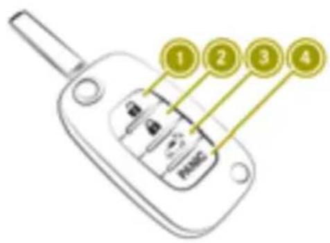
text_image
1 2 3 4① Unlocks the vehicle
② Locks the vehicle
③ smart fortwo coupé: Opens the upper tailgate (press and hold)
③ smart fortwo cabrio: Opens the soft top (press and hold)
④ PANIC Switches the panic alarm on and off (press and hold)
▶ To unlock centrally: press the 📋 button. The turn signals flash once.
i After unlocking, open the vehicle within approximately 2 minutes to prevent it from locking itself again and arming the anti-theft alarm system.
▶ To unlock and open the upper tailgate (smart fortwo coupé): press and hold the button.
▶ To open the soft top to the B-pillar (smart fortwo cabrio): press and hold the button.
▶ To lock centrally: press the 🔒 button. The turn signals flash twice.
▶ To switch the panic alarm on and off: press the PANIC button for approximately two seconds. An alarm sounds and the exterior lighting flashes.
Opening the door
▶ Press the ⏻ button on the SmartKey.
▶ Open the door.
i After unlocking, open the vehicle within approximately 2 minutes to prevent it from
locking itself again and arming the anti-theft alarm system.
Correct driver's seat position
WARNING
You could lose control of your vehicle if you do the following while driving:
- adjust the driver's seat, steering wheel or mirrors
- fasten the seat belt
There is a risk of an accident.
Adjust the driver's seat, steering wheel or mirrors and fasten your seat belt before starting the engine.
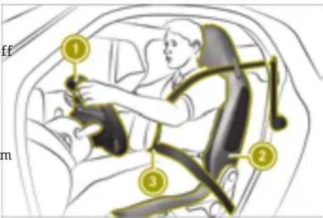
text_image
ff m 1 2 3Observe the following rules on the correct driver's seat position:
- the driver must be as far away from the driver's air bag as possible page 37).
- the driver must be wearing seat belt ③ properly.
- the driver must be able to depress the pedals properly.
- the driver must be able to move their legs freely.
- the driver must be able to reach steering wheel ① with their arms slightly bent.
- the driver must be able to see all the displays in the instrument cluster clearly.
- move seat backrest ② to an almost vertical position.
- you are sitting in a normal upright position.
-
the seat belt must fit snugly across your ^n body.
-
the seat belt must be routed across the middle of your shoulder.
- the seat belt must be routed in your pelvic area across the hip joints.
- adjust the rear-view and exterior mirror so that the driver has a good view of the road and traffic conditions.
Adjusting the seats
Please note

WARNING
Children could become trapped if they adjust the seats, particularly when unattended. There is a risk of injury.
When leaving the vehicle, always take the SmartKey with you and lock the vehicle. Never leave children unsupervised in the vehicle.

WARNING
If the driver's seat is not engaged, it could move unexpectedly while the vehicle is in motion. This could cause you to lose control of the vehicle. There is a risk of an accident.
Always make sure that the driver's seat is engaged before starting the vehicle.

WARNING
When you adjust a seat, you or other vehicle occupants could become trapped, e.g. on the seat guide rail. There is a risk of injury.
Make sure when adjusting a seat that no one has any body parts in the sweep of seat.
for example. This poses an increased risk of injury or even fatal injury.
Adjust the seat properly before beginning your journey. Always ensure that the backrest is in an almost vertical position and that the shoulder section of your seat belt is routed across the center of your shoulder.

WARNING
If the steering wheel is unlocked while the vehicle is in motion, it could change position unexpectedly. This could cause you to lose control of the vehicle. There is a risk of an accident.
Before starting off, make sure the steering wheel is locked. Never unlock the steering wheel while the vehicle is in motion.

WARNING
You could lose control of your vehicle if you do the following while driving:
- adjust the driver's seat, steering wheel or mirrors
- fasten the seat belt
There is a risk of an accident.
Adjust the driver's seat, steering wheel or mirrors and fasten your seat belt before starting the engine.
! Make sure that there are no objects in the footwell under or behind the seats when moving the seats back. There is a risk that the seats and/or the objects could be damaged.
Observe the safety notes on "Air bags" (▷ page 38) and "Children in the vehicle" (▷ page 42).

WARNING
The seat belt does not offer the intended level of protection if you have not moved the backrest to an almost vertical position. When braking or in the event of an accident, you could slide underneath the seat belt and sustain abdomen or neck injuries,
Adjusting the seat fore-and-aft position
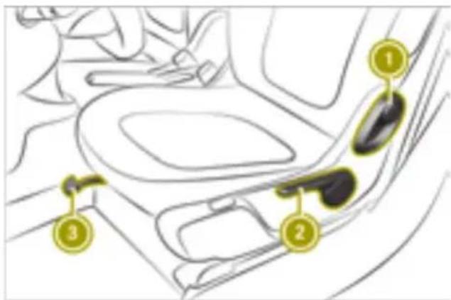
text_image
Diagram of car interior with numbered labels pointing to different sections of the seat areaSeat with a lever
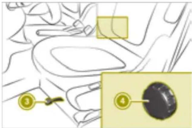
text_image
Diagram showing a car interior with labeled parts, including a highlighted section and numbered annotations.Seat with a handwheel
To adjust the seat fore-and-aft position, the seat belt must not be fastened.
▶ Lift lever ③.
▶ Slide the seat forward or back. The seat engages audibly.
Adjusting the seat height (seat with a lever only)
▶ Pull handle ② up or push it down several times.
Adjusting the seat backrest (seat with a lever)
▶ Pull lever ① forward.
▶ At the same time, move the backrest forward or back.
Adjusting the seat backrest (seat with a handwheel)
▶ Turn handwheel ④ forward or back.
Adjusting the mirrors
Adjusting the rear-view mirror
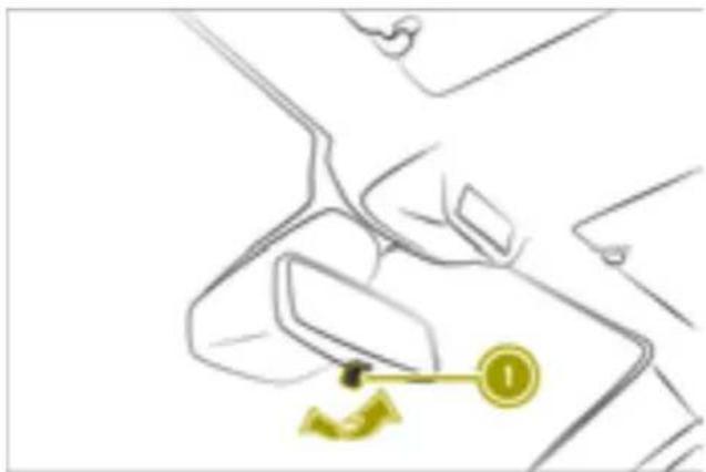
natural_image
Line drawing of a hand holding a device with a yellow circular icon and arrow, no text or symbols present▶ Move the rear-view mirror up, down, left or right.
Manually setting the rear-view mirror to anti-glare mode
▶ Fold lever ① forward.
Understanding the automatic anti-glare rear-view mirror
Please note
WARNING
Electrolyte may escape if the glass in an automatic anti-glare mirror breaks. The electrolyte is harmful and causes irritation. It must not come into contact with your skin, eyes, respiratory organs or clothing or be swallowed. There is a risk of injury.
If you come into contact with the electrolyte, observe the following:
- Rinse off the electrolyte from your skin immediately with water.
- Immediately rinse the electrolyte out of your eyes thoroughly with clean water.
- If the electrolyte is swallowed, immediately rinse your mouth out thoroughly. Do not induce vomiting.
- If electrolyte comes into contact with your skin or hair or is swallowed, seek medical attention immediately.
- Immediately change out of clothing which has come into contact with electrolyte.
- If an allergic reaction occurs, seek medical attention immediately.
Useful information
The rear-view mirror automatically goes into anti-glare mode if simultaneously:
• the ignition is switched on
- incident light from headlamps hits the sensor in the interior mirror
The rear-view mirror does not go into anti-glare mode if reverse gear is engaged or if interior lighting is switched on.
Adjusting the exterior mirrors manually

WARNING
You could lose control of your vehicle if you do the following while driving:
- adjust the driver's seat, steering wheel or mirrors
- fasten the seat belt
There is a risk of an accident.
Adjust the driver's seat, steering wheel or mirrors and fasten your seat belt before starting the engine.

WARNING
The exterior mirror on the front-passenger side reduces the size of the image. Visible objects are actually closer than they appear. This means that you could mis-judge the distance from road users traveling behind, e.g. when changing lane. There is a risk of an accident.
For this reason, always make sure of the actual distance from the road users traveling behind by glancing over your shoulder.
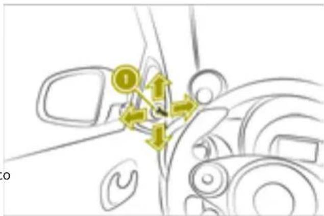
text_image
Diagram showing directional arrows and a numbered point 'O' on a vehicle's head panel, likely indicating movement or positioning.▶ Move lever ① up, down, left or right.
the Adjusting the exterior mirrors electrically
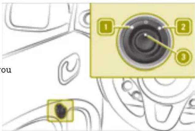
text_image
1 2 3 ouIn order to adjust the exterior mirrors electrically, the ignition must be switched on.
▶ To select the left or right exterior mirror: turn control ③ left 1 or right 2.
▶ To adjust the exterior mirrors: move control ③ up, down, left or right.
Starting the engine
Please note

WARNING
If children are left unsupervised in the vehicle, they could:
- open the doors, thus endangering other people or road users.
• get out and disrupt traffic.
• operate the vehicle's equipment.
Additionally, children could set the vehicle in motion if, for example, they: - release the parking brake.
- shifting the automatic transmission out of park position P
- Start the engine.
There is a risk of an accident and injury. When leaving the vehicle, always take the SmartKey with you and lock the vehicle.
Never leave children or animals unattended in the vehicle. Always keep the Smart-Key out of reach of children.

WARNING
If you attach heavy or large objects to the SmartKey, the SmartKey could be unintentionally turned in the ignition lock. This could cause the engine to be switched off. There is a risk of an accident.
Do not attach any heavy or large objects to the SmartKey. Remove any bulky key rings before inserting the SmartKey into the ignition lock.
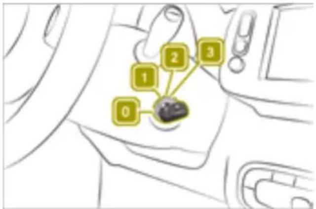
text_image
1 2 3 00 To insert the SmartKey into the ignition lock
1 To switch on the power supply
2 To switch on the ignition
3 To start the engine
Automatic transmission
▶ Turn the SmartKey to position 3.
The READY indicator appears in the instrument cluster. A tone sounds.
▶ Shift out of transmission position P or N.
Pulling away
Please note

WARNING
Objects in the driver's footwell may restrict the clearance around the pedals or block a depressed pedal. This jeopardizes the operating and road safety of the vehicle. There is a risk of an accident.
Stow all objects securely in the vehicle so that they do not get into the driver's foot-well. When using floormats or carpets, make sure that they are properly secured so that they do not slip or obstruct the pedals. Do not place several floormats or carpets on top of one another.

WARNING
Unsuitable footwear can hinder correct usage of the pedals, e.g.:
• shoes with thick soles
• shoes with high heels
- slippers
There is a risk of an accident.
Wear suitable footwear to ensure correct usage of the pedals.

WARNING
If you switch off the ignition while driving, safety-relevant functions are only available with limitations, or not at all. This could affect, for example, the power steering and the brake boosting effect. You will require considerably more effort to steer and brake. There is a risk of an accident. Do not switch off the ignition while driving.

WARNING
If you operate mobile communication equipment when driving, you may be distracted from the traffic situation. You could also lose control of the vehicle. There is a risk of an accident.
Only operate this equipment when the vehicle is stationary.
Note the following when pulling away:
- Do not drive with the parking brake applied.
- Use caution when pulling away on slippery surfaces.
- Do not allow tires to spin.
- Depress the brake pedal and keep it depressed.
- Press the release button on the selector lever.
- Shift the gear selector lever to position or .
Drinking and driving

WARNING
Drinking and driving and/or taking drugs and driving are very dangerous combinations. Even a small amount of alcohol or drugs can affect your reflexes, perceptions and judgment.
The possibility of a serious or even fatal accident is greatly increased when you drink or take drugs and drive.
Do not drink or take drugs and drive or allow anyone to drive who has been drinking or taking drugs.
Using the parking brake
Observe the legal requirements for the counPlease note
try in which you are driving. Some jurisdictions prohibit the driver from using a mobile
phone while driving a vehicle.
If you make a call while driving, always use hands-free mode. Only use the telephone when the traffic situation permits. If you are unsure, pull over to a safe location and stop before using the telephone.
Bear in mind that at a speed of only 30 mph (approximately 50 km/h), the vehicle covers a distance of 44 ft (approximately 14 m) per second.

WARNING
If the parking brake has not been fully released when driving, the parking brake can:
• overheat and cause a fire
- lose its hold function.
^h There is a risk of fire and an accident.
^a Release the parking brake fully before driving off.

WARNING
If you must brake the vehicle with the parking brake, the braking distance is
considerably longer and the wheels could lock. There is an increased danger of skidding and accidents.
Only use the parking brake to brake the vehicle when the service brake is faulty. I not apply the parking brake too firmly. If the wheels lock, release the parking brake until the wheels begin turning again.

WARNING
If you leave children unsupervised in the vehicle, they could set it in motion by, for example:
- release the parking brake.
- shift the automatic transmission out of the parking position P.
- start the engine.
In addition, they may operate vehicle equipment and become trapped. There is a risk of an accident and injury.
When leaving the vehicle, always take the SmartKey with you and lock the vehicle. Never leave children unsupervised in the vehicle.
Applying the parking brake
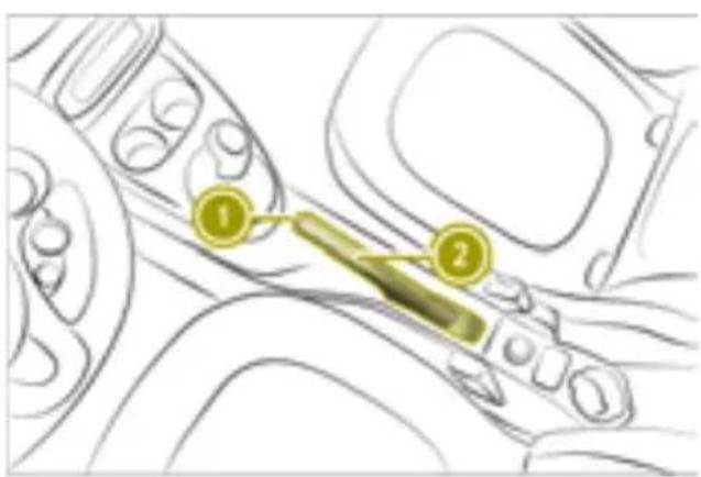
text_image
Diagram of a car interior showing two labeled parts with numbered annotations▶ Pull parking brake ② up.
The brake lights do not light up when you brake the vehicle with the parking brake.
Release Parking Brake
▶ Depress the brake pedal and keep it depressed.
▶ Press release button ① on parking brake ② and move the parking brake down to the stop.
Hill start assist

WARNING
After a short time, hill start assist will no longer brake your vehicle and it could roll away. There is a risk of an accident and injury.
Therefore, quickly move your foot from the brake pedal to the accelerator pedal. Never leave the vehicle when it is held by hill start assist.
Hill start assist keeps the vehicle in place when driving uphill as soon as the brake pedal is released.
Hill start assist is only active in the following situations:
- when pulling away on an uphill slope
- when the parking brake is released
• the transmission is not in position N - ESP® is functioning correctly
▶ Release the brake pedal.
The vehicle is then held for about one second.
▶ Pull away.
Automatic transmission
Please note

WARNING
The automatic transmission switches to neutral position N when you switch off the engine. The vehicle may roll away. There is a risk of an accident.
Before switching off the engine, always switch to parking position P. Prevent the parked vehicle from rolling away by applying the parking brake.
Transmission position display
! Only engage park position P when the To reach maximum acceleration, use kick-vehicle is stationary. Otherwise, you could down: damage the transmission.
▶ Depress the accelerator pedal beyond th
! Only shift into reverse gear R when the vehicle is stationary. Otherwise, you could damage the transmission.
! Only shift into neutral N when the vehicle is stationary. Otherwise, you could damage the transmission.
To reach maximum acceleration, use kickdown:
▶ Depress the accelerator pedal beyond the pressure point.
▶ Ease off the accelerator pedal once the desired speed is reached.
The following transmission positions are available:
• P Park position
Position P should not be used to brake the vehicle when parking. To secure the vehicle, apply the parking brake in addition to shifting to transmission position P.
- R Reverse gear
• N Neutral
No power is transmitted from the engine to the drive wheels.
D Drive
Changing the transmission position
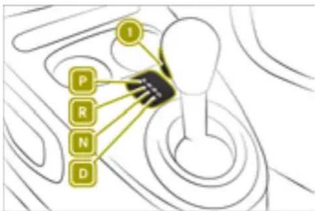
flowchart
graph TD
    A["Hand"] --> B["P"]
    A --> C["R"]
    A --> D["N"]
    A --> E["D"]
    A --> F["I"]
P Park position with parking lock
R Reverse gear
N Neutral
D Drive
The ignition must be switched on in order shift the transmission to positions P, N R. To shift the transmission from position you must also depress the brake pedal.
▶ Press release knob ①.
▶ Shift the selector lever to the desired transmission position.
Maximum acceleration (kickdown)
Using the turn signals
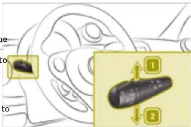
text_image
Diagram showing a remote control device with labeled parts and directional arrows indicating movement or positioning.The ignition must be switched on in order to use the turn signals.
▶ To indicate: press the combination switch in the direction of arrow 1 (right) or 2 (left) past the point of resistance.
▶ To indicate briefly: press the combination switch briefly to the point of resistance. The turn signal flashes three times.
Acoustic presence indicator
Useful information
Vehicles with an electric motor generate much less driving noise than vehicles with internal combustion engines. As a result, your vehicle may not be heard by other road users in certain situations.
In order to allow your vehicle to be heard when it is moving at slow speeds, a sound generator installed in the vehicle produces a specific noise at speeds between 0 and 18 mph (30 km/h). This function is called the acoustic presence indicator. It makes it possible for other road users, especially pedestrians and cyclists, to hear the vehicle bet-
ter. The acoustic presence indicator can also be heard in the vehicle interior.
cient, steady driving style. The speed is reduced to approx. 70 mph (110 km/h).
The volume of the acoustic presence indica- • Output of air conditioning and heating is tor depends on the engine speed. The greater reduced.
the acceleration, the louder the noise. At speeds of over 18 mph (30 km/h), the noise is less accelerated.
switched off. Above this speed, the driving noise naturally created by the vehicle is typically sufficient for the vehicle to be heard in good time by other road users. In order to increase acceleration in ECO mode, press the accelerator pedal beyond the pressure point.
Driving economically
Notes on economical driving
In order to save energy, smart electric drive recuperates part of the kinetic energy and uses it to charge the high-voltage battery. When the driver releases the accelerator, the vehicle is braked.
In the following cases, the vehicle will slow down only partially or not at all when the accelerator pedal is released:
- the gear lever is in position D and the vehicle is rolling backwards
- the gear lever is in position R and the vehicle is rolling forwards
On steep slopes, the vehicle may not be held at all or may only be held to a limited exten
In the following cases recuperation is restricted:
- the high-voltage battery is fully charged or too cold
- the power electronics or the engine has overheated
Recommendations for driving economically:
• accelerate moderately
- pay attention to the power display (▷ page 57)
- drive with care
- use the air conditioning and electrical consumers in moderation
• have maintenance work carried out at the specified service intervals
ECO mode can be used to save additional energy.
ECO mode has the following characteristics:
- Reduced torque and significantly reduced power. This supports a particularly effi-
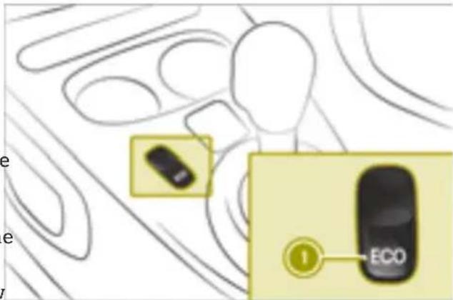
text_image
ECOSwitching ECO mode on and off
▶ Press button ①. If the energy-saving function is activated, the FCOO display is shown in the on-board computer.
The energy-saving function is switched off when the ignition is restarted.
Power and charge level display
Useful information
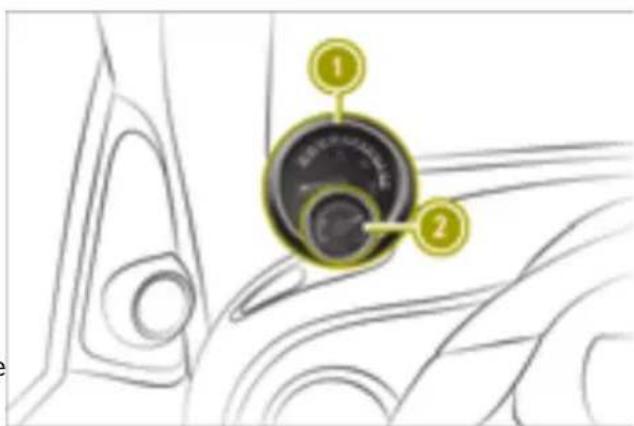
text_image
Diagram showing a car interior with labeled parts, including numbered annotations 1 and 2 pointing to a circular component.① Power display
② Charge level display
Power display ① together with charge level display ② can be positioned to the left or to
the right. When the vehicle is unlocked, the The high-voltage battery has reached the charge level display lights up. reserve level in the following cases:
Power display
! Do not hang any objects on the power display.
This could cause the dashboard clock to torn out of its anchorage point and be severely damaged.
- The Battery Reserve Level message appears in the display.
- When the red area of condition of charge display ② has been reached.
b) Charge the high-voltage battery when the condition of charge falls below 20%.
Power display ① contains two areas:
• Area to the right of 0
The current power that the high-voltage battery provides is shown here. 100% corresponds to the peak performance of the high-voltage battery.
• Area to the left of 0
The vehicle's level of recuperation in over A higher percentage indicates a more eco-run mode and when braking is shown here nomical driving style.
Understanding the eco score display in the on-board computer
Useful information
The eco score display provides information on how to drive economically.
The LED ring in power display ① shows the power output available.
When the needle of power display ① is in ignition remains switched off for longer than "OFF" position, the vehicle cannot be driven4 hours, the eco score display will be reset. for the following reasons:
• The ignition is switched off.
- The gear lever has not been moved to position N or P to start the drive system.
- The charging cable is still connected to the vehicle socket.
- There is insufficient power available from the high-voltage battery.
- There is a malfunction in the vehicle's high-voltage electrical system.
Color display
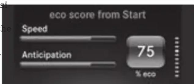
text_image
eco score from Start Speed Anticipation 75 % ecoWhen the drive system is started, power disThe percentage in the eco score display is play needle ① is at position "0". The READY calculated using the following categories:
indicator appears in the instrument cluster. • Speed: the value increases when driving at A tone sounds. The vehicle is ready for driv-low speeds.
ing.
Charge level display
! Do not hang any objects on the charge level display.
Otherwise, the display could be torn out its anchorage and be damaged.
Using the eco score display in the smart Media-System
Charge level display ② displays the chargeCalling up the eco score menu
level of the high-voltage battery as a percentage.
▶ Select Vehicle > ecos score.
Evaluating the current trip
▶ Select Current trip.
The following rating information and values appear:
- Bar graphs for accelerate, anticipatory and shift
• Bar graphs for Speed and Anticipation
• Distance covered
• Total eco score as a percentage
Saving the current trip
▶ Select Current trip >Save.
▶ Select the category under which you want to save the trip.
The values for the current trip will be added to the category selected and the current trip will be reset. In the instrumentscore display will be reset. cluster, the trip computer values will be returned to "From reset".
The values for the current trip will be added to the category selected and the current trip will be reset. In the instrument To activate: select Current trip > + > cluster, the values for the "From start" trip Show eco score after trip.
computer and eco score display will be reset.
Comparing the current trip with the saved trips from a category
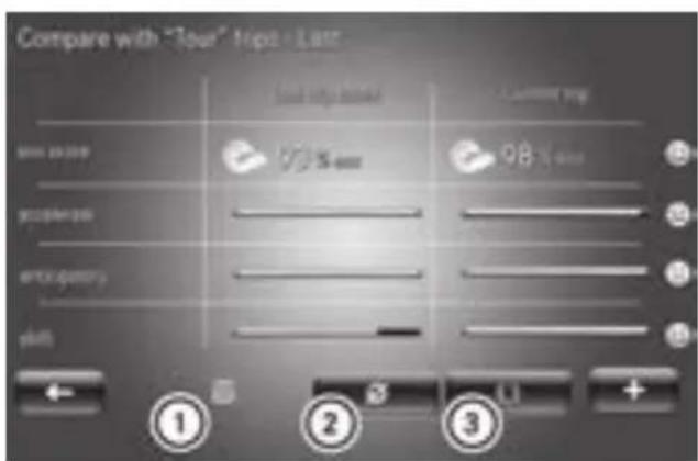
text_image
Compare with "Tour" Trip / Last Last trip level 98% 98% ① ② ③ +① Last trip saved in this category
② Average value for the category
③ Best trip in the category
▶ Select Current trip > + > Compare.
▶ Select category.
A comparison of the values for the current trip with the values of the selected category appears.
▶ Select the comparison value ①, ② or ③. The current trip is compared to the respective comparison value from the category.
Resetting the current trip data
▶ Select Current trip >Reset.
▶ Select Yes.
In the instrument cluster, the trip computer values will be returned to "From reset".
In the instrument cluster, the values for the "From start" trip computer and eco
Activating/deactivating eco score after a trip
To activate: select Current trip > + > ip Show eco score after trip.
▶ To deactivate: selectcuenentrrip > + > Hide eco score after trip.
Displaying eco score for saved trips in a category
▶ Select Vehicle > eco score > My preferred trips.
▶ Select category.
eco score contains the following comparison values for each category:
- Summary
- Last value
- Average value
- Best value
The following types of evaluations are available for the last trips saved category:
- Summary
- Detailed report
Renaming a category
At least one trip must be stored in the respective category.
▶ Select Vehicle > eco score > My preferred trips > + > Rename this category.
Resetting the eco score of one category
At least one trip must be stored in the restive category.
▶ Select Vehicle > eco score > My preferred trips > + > Reset this category.
Braking correctly
Please note

WARNING
If you rest your foot on the brake pedal while driving, the braking system can overheat. This increases the stopping distance and can even cause the braking system to fail. There is a risk of an accident. Never use the brake pedal as a footrest. Never depress the brake pedal and the accelerator pedal at the same time.
The vehicle slows down as soon as the accelerator pedal is released. This aids recuperation as the engine is used as a generator and charges the high-voltage battery.
Braking on steep downhill gradients
When driving on downhill gradients, observe the following rules:
- Do not move the gear lever to position N.
- If recuperation is restricted, also brake at intervals.
Braking on wet road surfaces
There may be a delayed brake response when driving on wet roads, after driving through a car wash or after driving through deep water.
- Maintain a greater distance from the vehicle in front.
▶ Brake more firmly.
Braking on salt-treated roads
If you drive on salt-treated roads, a layer of salt may form on the brake discs and pads. This increases the vehicle's braking distance.
In order to prevent any salt build-up, apply the brakes occasionally while paying attention to the traffic conditions.
▶ Brake carefully at the end of the journey and when starting the next journey.
- Maintain a greater distance to the vehicle in front.
Maintaining the brakes
! The brake fluid level may be too low, if:
- if the red brake warning lamp lights up in the instrument cluster and - you hear a warning tone while the engine is running
Observe additional warning messages in the multifunction display.
The brake fluid level may be too low due to brake pad wear or leaking brake lines.
Have the brake system checked immediately. Consult a qualified specialist workshop to arrange this.
A function or performance test should only be carried out on a 2-axle dynamometer. If you wish to operate the vehicle on such a dynamometer, please consult a qualified specialist workshop in advance. You could otherwise damage the drive train or the brake system.
As the ESP system operates automatically, the engine and the ignition must be switched off (the SmartKey must be in position 0 or 1 in the ignition lock) if:
- the parking brake is tested using a brake dynamometer (maximum 10 seconds).
- the vehicle is towed with the front axle raised.
Braking triggered automatically by ESP may seriously damage the brake system.
All checks and maintenance work on the brake system must be carried out at a qualified specialist workshop.
Have brake pads/linings installed and brake fluid replaced at a qualified specialist workshop.
If the brake system has only been subject to moderate loads, you should test the functionality of your brakes at regular intervals. When having brake pads/linings installed, smart recommends that you only use those which are approved for smart vehicles or are of an equivalent quality standard. Brake pads/linings which have not been approved for smart vehicles or which are not of an equivalent quality could affect your vehicle's operating safety.
Driving on wet roads
Hydroplaning
Depending on driving style and tire tread depth, hydroplaning can occur on the road. Adapt your driving style as follows:
▶ Reduce the speed.
▶ Brake carefully.
▶ Avoid sudden steering movements
▶ Avoid tire ruts.
Fording
! Bear in mind that vehicles traveling in front or in the opposite direction create waves. This may cause the maximum permissible water depth to be exceeded.
Failure to observe these notes may result in damage to the engine, electrical systems and transmission.
Prevent water from entering the vehicle interior or the engine compartment. Observe the following when driving through standing water:
▶ The water level should not exceed the lower edge of the vehicle body in still water
▶ Drive no faster than walking pace.
Winter driving
▶ Before the start of winter, have the vehicle check checked at a qualified specialist workshop.
▶ Use winter tires and, if applicable, snow chains.
▶ Drive carefully and avoid sudden acceleration, turning and braking on slippery road surfaces.
▶ Do not use cruise control.
▶ If the vehicle skids, take corrective steering actions to counteract the movement.
▶ If the vehicle skids, shift the transmission to position N.
▶ Do not use the outside temperature display as a way to determine if conditions are icy.
▶ Observe the road surface.
Using cruise control
Please note

WARNING
If you call up the stored speed and it is different to the current speed, the vehicle will accelerate. If you are not aware of the stored speed, the vehicle may accelerate unexpectedly. There is a risk of an accident.
Pay attention to the road and traffic conditions before calling up the stored speed. If you do not know the stored speed, store the desired speed again.
Cruise control is used in order to drive at a constant speed for a prolonged period.
The driver is responsible for driving the vehicle in a safe manner, controlling the vehicle speed and braking in good time.
If there is a change of drivers, inform the new driver of the speed stored.
Cruise control requires:
- favorable weather and good visibility
• good road and traffic conditions
Cruise control does not brake the vehicle automatically.
- reduce the vehicle speed by applying the brakes.
Speed regulation is canceled when the following occur:
- braking (including the parking brake)
- ESP® intervention
On downhill gradients or when accelerating briefly, cruise control may interrupt speed regulation. Afterwards, the set speed is applied again.
Cruise control is ready for use at speeds above 25 mph (40 km/h).
Interrupting cruise control
▶ Press CANCEL button ④. The stored speed can be accessed again later.
The stored speed is deleted when the engine is switched off.
Calling up the stored speed
▶ Press RES button ③.
▶ Remove your foot from the accelerator pedal.
Deactivating cruise control
▶ Press button ① to the OFF center position. The symbol in the instrument cluster display goes out. The stored speed is deleted.
The stored speed is deleted when the engine is switched off.
Activating cruise control
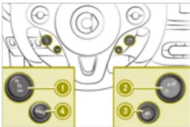
text_image
Diagram showing car control panel with numbered buttons and labeled ports, likely for vehicle or system control.▶ Press the upper section of button ①. The symbol appears in the instrument cluster display.
Storing the current speed
▶ Press SET + button ②.
▶ Remove your foot from the accelerator pedal.
SEH appears in the instrument cluster display.
Adjusting the stored speed
▶ Press (+) or (-) button ② until the desired electrical system checked by a qualified speed is reached. specialist workshop.
Charging the high-voltage battery
Please note

DANGER
The vehicle's high-voltage electrical system is under high voltage. If you modify components in the vehicle's high-voltage electrical system or touch damaged components, you may be electrocuted. The components in the vehicle's high-voltage electrical system may be damaged in an accident, although the damage is not visible. There is a risk of fatal injury.
Following an accident, do not touch any high-voltage components and never modify the vehicle's high-voltage electrical system. Have the vehicle towed away after an accident and the vehicle's high-voltage electrical system checked by a qualified specialist workshop.

WARNING
In the event of a vehicle fire, the internal pressure of the high-voltage battery can exceed a critical value. In this case flammable gas escapes through a ventilation valve on the underbody. The gas can ignite. There is a risk of injury.
Leave the danger zone immediately. Secure the danger area at a suitable distance, whilst observing legal requirements.

DANGER
Connecting the charging cable to the mains supply via incorrectly installed mains sockets or by means of adapters, extension cables or similar could cause a fire or an electric shock. There is a risk of fatal injury.
To avoid hazardous situations, observe the following:
- Only connect the charging cable to mains sockets:
- which have been properly installed and
- which have been inspected by a qualified electrician
- For safety reasons, only use the charging cables supplied with the vehicle, or charging cables which have been approved for use with this vehicle.
- Never use a damaged charging cable.
- Do not use:
- extension cables
- extension reels
- multiple sockets
- Never use socket adapters to connect the charging cable to the mains socket. The only exception being if the adapter has been tested and approved by the manufacturer for charging the high-voltage battery of an electric vehicle.
- Observe the safety notes in the operating instructions for the socket adapter.

DANGER
Connecting the charging cable to the wall-box via an incorrectly installed wallbox or adapter, extension cable or similar could cause a fire or an electric shock. There is a risk of fatal injury.
To avoid hazardous situations, observe the following:
- Only connect the charging cable to a wallbox that:
- is installed correctly and
- has been inspected by a qualified electrician
- For safety reasons, only use charging cables that have been tested and approved by the manufacturer for charging the high-voltage battery in an electric vehicle.
- Never use damaged charging cables.
- Do not extend the charging cable.
- Do not use an adapter.
- Always observe the safety notes in the wallbox's operating instructions.
The vehicle's high voltage electrical system is under high voltage.
- Do not tamper with the high-voltage components or the orange cables of the high-voltage electrical system.
- Do not touch the high-voltage components or the orange cables of the high-voltage electrical system in a vehicle which has been involved in an accident.
- Do not touch damaged components or the damaged orange cables of the high-voltage electrical system.
- Do not remove the covers of the high-voltage electrical system components which are marked with a yellow warning sticker.
For safety reasons, only use the charging cable which is supplied with the vehicle or which has been approved by smart for this vehicle.
Do not clean the vehicle whilst charging.
Useful information
Method of operation
The vehicle is equipped with a high-volta battery for driving. The high-voltage battery stores the energy needed to operate
electric motor and releases it again.
The electric motor uses energy stored in
high-voltage battery for pulling away and accelerating.
In overrun mode, kinetic energy is converted into electrical energy by recuperation and stored in the high-voltage battery.
The high-voltage battery can be charged as follows:
- by recuperation while the vehicle is in motion
- with the suitable charging cable at a main socket while the vehicle is stationary
- with the suitable charging cable at a wall box while the vehicle is stationary
- with the suitable charging cable at a charging station while the vehicle is stationary
Not all charging variants are available in countries.
The high-voltage battery can be charged voltage range from 100 V to 240 V.
If possible only charge the high-voltage battery when the charge is below 80%. Charge the high-voltage battery at the latest when the charge falls below 20%.
Discharged high-voltage battery
The high-voltage electrical system switches off if the high-voltage battery is completely discharged. This protects the high-voltage battery from exhaustive discharge.
Switching the ignition on and then off can reactivate the high-voltage electrical system temporarily. This allows the vehicle to be parked safely.
Do not allow the vehicle's high-voltage battery to remain in a discharged or almost full discharged state for more than 14 days. You can check the condition of charge in the charge level display ▷(page 57).
Extreme outside temperatures
The efficiency of the high-voltage battery is temperature-dependent and is significantly
reduced at low or very high temperatures. In addition, the electrolytes used may freeze at very low temperatures.
The LED ring in power display shows the power output available (page 57).
Energy consumption and range
The available energy in the high-voltage battery is fundamentally reduced by the following factors:
- low outside temperatures
- operating the air-conditioning system or heating
ns•switching on electrical consumers
Low outside temperature and prolonged periods of inactivity without charging can have the following effects:
- the high-voltage battery output is significantly reduced
- charging periods may be longer
ll range can be significantly reduced
In extreme cases, it may not be possible to start the vehicle as a result. You should therefore always ensure that the high-voltage battery is fully charged or that the charging cable is connected when parking the vehicle for an extended period of time at low outside temperatures.
As the gets older, the capacity of the high-voltage battery will diminish in the course of its lifetime. This reduces the maximum range and the maximum acceleration.
Battery care
Observe the following notes on battery care:
- avoid storing and transporting the vehicle at high temperatures and over an extended period of time (e.g. transporting it in a container)
- connect the vehicle to a power supply
11y when parking it for an extended period of
time
• temperatures below -13 ^ (-25 ^ ) for more than seven days can cause irreversible damage to the vehicle due to frost damage
Conditions of use
Observe the information on exceptions and limitations in the warranty documentation and in the Maintenance Booklet.
Voltage surge protection device
! Voltage surges in the mains supply can damage the vehicle. The vehicle is therefore equipped with a device which protects it from voltage surges in the mains supply. This device may be triggered during severe thunderstorms, for example, and may lead to the building's fuse being tripped and an interruption in the power supply. These functions protect the vehicle. After the building fuse is switched on again, the charging process resumes automatically. Following an interruption in the power supply without the building's fuse being tripped, it may take up to 10 minutes for charging to resume automatically.
After the device has triggered, switch the building's fuse unit on again. Otherwise, the charging process will not resume.
Heat generated by the charging cable and charging cable connector
Charging cables and charging cable connectors may heat up during the charging process at a mains socket.
In the following cases, the rise in temperature is within the permitted limits:
• infrastructure of the mains power supply and the charging cable are intact
- instructions for handling the charging cable and controls on the charging cable are followed
If an increase in temperature to above the permitted limits does take place, check the infrastructure of the mains power supply.
Understanding the vehicle socket
Overview vehicle socket
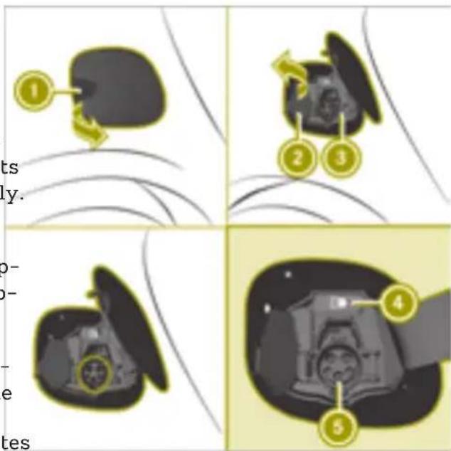
text_image
1 2 3 4 5 its ly. o- o- e tes① Charge socket flap
② Socket cap
③ Catch
④ Indicator lamp
⑤ Vehicle socket
Indicator lamp on the vehicle socket
The indicator lamp on the vehicle socket has the following meaning:
| Indicator lamp | |
| Flashes green slowly | High-voltage battery is being charged. |
| Lights up green | High-voltage battery is fully charged. |
| Flashes orange slowly | Vehicle waiting for charging to start. |
| Flashes orange | Vehicle is paused from charging. |
| Flashes red quickly | A malfunction occurred during charging. |
Charging the battery using a mains socket
Useful information
Charging cable
! Only use the charging cable to charge the high-voltage battery. Do not use the charging cable for other purposes. It may otherwise be damaged.
The charging cable for connection to a mains socket is included in the scope of delivery. Only use the charging cable which is supplied with the vehicle and which has been approved by smart for this vehicle.
For transportation, wrap the charging cable around the control panel or secure it to the control panel housing.
Control panel on charging cable
Do not leave the control panel on the charg-Flashes ing cable hanging loose from a mains socketorange Otherwise, this could lead to a bad contact with the mains socket and to malfunctions when charging the vehicle.
Do not lift up or transport the control panel by the charging cable connector or the mains plug.
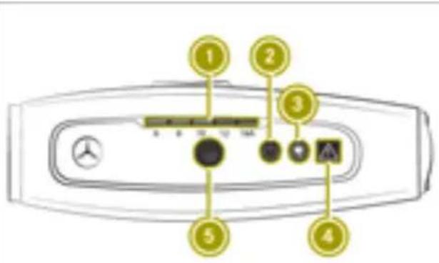
text_image
Diagram of a car air conditioner panel with numbered labels pointing to key components① Indicator lamp, charge current setting
② Indicator lamp, mains voltage
③ Indicator lamp, charging process
④ Indicator lamp, protection and control module
⑤ Button for setting the charge current
The indicator lamps on the charging cable have the following meaning:
Indicator lamp ①
| Lights up green | Value is set as the desired charging current. |
| Flashes orange | Depending on the mains socket, the value cannot be set as the desired charging current. |
Indicator lamp ②
| Lights up green | Mains voltage is connected. The high-voltage battery can be charged. |
Indicator lamp ③
| Lights up green | High-voltage battery is being charged. |
| -Flashes torange | Connection to the vehicle is established. |
Indicator lamp ④
| Lights up red | The current at the control panel is not correct. The high-voltage battery cannot be charged. |
Setting the charge current
WARNING
If the charge current draw via a mains socket is too high during the charging process, the external electrical system may overheat. There is a risk of fire. Before beginning the charging process, check the maximum permissible charge current locally. Consult a qualified expert to do so where necessary.
If necessary, adjust your vehicle's settings.
An excessive charge current can blow a fuse or lead to overheating of the external power supply. Check whether the external power supply is compatible with the set charge current. If necessary, lower the set
charge current or use another power socket.
The value of the charge current used to charge the high-voltage battery can be limited. This may protect the mains supply from overloads.
The maximum setting value and the adjustment values may vary from country to country.
The preset default value is the minimum setting. This is the minimum charge current available from the mains supply.
If the charging cable remains in the mains socket after charging, the value set will be adopted the next time you start charging. If the charging cable is disconnected from the mains socket, the value will be reset to the minimum setting the next time you start charging.
▶ Check the maximum permissible charge current for the particular mains socket.
▶ Plug the cable connector into the mains socket.
You have one minute to set the charge rent.
▶ Press button ⑤ repeatedly until the indicator lamp in the desired setting lights up green.
The desired value is set.
i After one minute, the charge current can only be set by restarting. To do so, remove the charging cable from the mains supply and reinsert it into the mains socket.
Connecting a charging cable
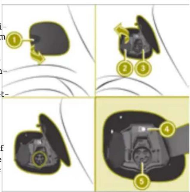
text_image
Diagram illustrating four steps of a device operation with numbered instructions and labeled components① Charge socket flap
② Socket cap
③ Catch
④ Indicator lamp
⑮ Vehicle socket
▶ Switch the ignition off.
▶ Engage transmission position P.
▶ Open charge socket flap ① (▷ page 64).
▶ Release lock ③ on socket cap ②.
Socket cap ② opens.
Insert the mains plug into the mains socket, as far as it will go.
▶ Set the desired charge current
▶ Insert the charging cable connector into vehicle socket ⑤ as far as it will go. The high-voltage battery is being charged.
The high-voltage battery is fully charged when the E indicator lamp on the vehicle socket lights up green.
The vehicle must not be moved during charging. The gear lever cannot be moved from position P.
i The engine cooling system and battery cooling system may audibly switch on during charging depending on the temperature.
If charging the vehicle's high-voltage battery is taking longer than usual, check the maximum charge current settings.
Removing the charging cable
! Always disconnect the charging cable from the vehicle socket first. Disconnecting the charging cable from the stationary socket first could damage the charging cable connector.
The charging cable can be removed when the high-voltage battery is completely charged or charging has to be interrupted.
▶ Disconnect the charging cable from vehicle socket ⑤.
▶ Close socket cap ②.
▶ Close charge socket flap ①.
▶ Disconnect the charging cable from the mains socket.
▶ Stow the charging cable safely in the charging cable bag (page 68).
Charging the battery at a charging station or wall box
Charging stations without communications functionality
Charging stations without communications functionality must be activated before charging, e.g. by using an RFID card. To do this, please observe the notes of the operator of the charging station.
Connecting a charging cable
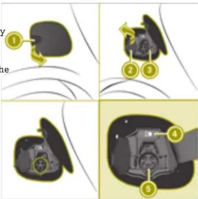
text_image
Y ne ① ② ③ ④ ⑤① Charge socket flap
② Socket cap
③ Catch
④ Indicator lamp
⑤ Vehicle socket
▶ Switch the ignition off.
▶ Engage transmission position P.
▶ Open charge socket flap ① (▷ page 64).
▶ Release locking mechanism ③ on socket or cap ②.
Socket cap ② opens.
▶ Insert the charging cable connector into vehicle socket ⑤ as far as it will go. The high-voltage battery is being charged.
The vehicle must not be moved during charging. The gear lever cannot be moved from position P.
The engine cooling system and battery cooling system may audibly switch on during charging depending on the temperature.
Removing the charging cable
▶ Press the 📋 button on the SmartKey. The 🕒 indicator lamp ④ above vehicle socket ⑤ goes out.
▶ Disconnect the charging cable from vehicle socket ⑤.
▶ Close socket cap ②.
▶ Close charge socket flap ①.
Storing the charging cable
! The charging cable must be stowed in the charging cable bag only to prevent it from being thrown around inside the vehicle.
▶ Stow the charging cable in the charging cable bag.
The charging cable bag is located in the trunk (▷ page 125).
Switching on the lighting
Useful information
The driver must ensure that the light settings match the current weather, light and traffic conditions.
For reasons of safety, smart recommends that you drive with the daytime driving lights or low beam headlamps switched on even during the daytime.
A warning tone sounds if the lights are still on when you leave the vehicle.
In some countries, operation of the head-lamps varies due to legal requirements and self-imposed obligations.
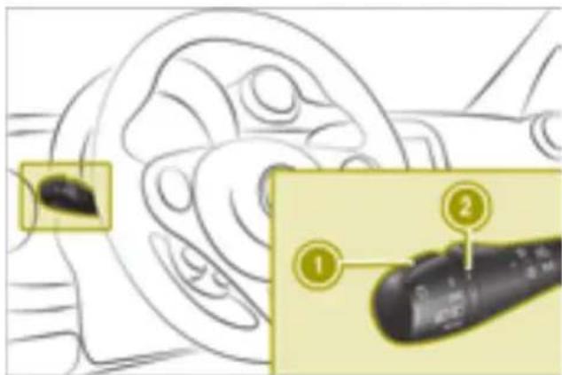
text_image
Diagram showing a device with labeled parts, including a highlighted section and numbered annotations.① Combination switch control
② Marking
Activating automatic headlamp mode

WARNING
When the light switch is set to AUTO, the low-beam headlamps may not be switched on automatically if there is fog, snow or other causes of poor visibility due to the weather conditions such as spray. There is a risk of an accident.
In such situations, turn the light switch to D.
▶ Turn combination switch control ① to the AUTO position.
If one or more of the following eventualities occurs, the lights are switched off automatically:
• the engine is switched off
at the driver's door is opened
the vehicle is locked
- the high-beam headlamps are not switched on when the vehicle is stationary
Switching on the low-beam headlamps
▶ Turn combination switch control ① to the position. The indicator lamp lights up in the instrument cluster.
Switching the high-beam headlamps on or off
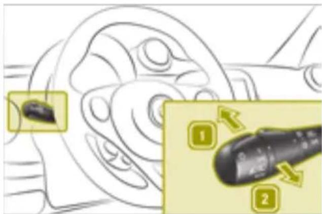
text_image
Diagram showing mechanical components with numbered annotations indicating directional changes or statesThe engine must be running.
▶ Turn the combination switch control to the AUTO or ≡D position.
▶ To switch on: press the combination switch in the direction of arrow 1.
▶ To switch off: move the combination switch back to its original position.
The indicator lamp in the instrument cluster lights up when the high-beam head-amps are switched on.
While the engine is running, the light setti is selected automatically according to the brightness of the ambient light. AUTO controls the daytime running lights, parking lamps and low beam headlamps. The automatic headlamp feature is only an aid. The driver is responsible for the vehicle's lighting at all times.
Using the high-beam flasher
▶ Pull the combination switch in the direction of arrow 2.
Switching the parking lamps on
▶ Turn combination switch control ① to the position.
Canada only: the parking lamps are only switched on when the engine is switched of. When the engine is running, the low beam headlamps are switched on.
Switching the fog lamps and rear fog lamp on and off
Only vehicles with front fog lamps are equipped with the "fog lamps" function.
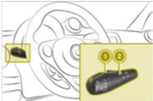
text_image
Diagram showing a mechanical component with two labeled parts (1 and 2) highlighting specific features.① Combination switch middle ring ② Marking
The ignition and either the parking lamps or low beam headlamps must be switched on in order to switch the fog lamps on.
The engine must be started and either the parking lamps or low beam headlamps switched on in order to switch the rear fog lamp on.
▶ To activate or deactivate manually, turn combination switch middle ring ① to the desired marking:
After releasing, the combination switch middle ring returns automatically to the neutral position.
The fog lamps and rear fog lamp also go out automatically in the following situations:
• the lights are switched off
- the engine is switched off and the control is in the AUTO position
Using the cornering light function
Only vehicles with the LED & Sensor package are equipped with the cornering light function.
The cornering light function uses the front fog lamp to improve the illumination of the road in the direction in which you are turning, enabling better visibility in tight bends, for example.
The following conditions must be fulfilled for the cornering light function to switch on automatically:
o-the low-beam headlamps are switched on
• the vehicle is moving at less than 25 mph (40 km/h)
- the turn signal is switched on or the steering wheel is turned
Using the interior lighting
Switching the interior lighting on and off
The interior lights go on when you unlock the doors.
The interior lights switch off in the following situations:
• a door is opened and 15 minutes have passed
- all doors are closed, the vehicle has been locked and 15 seconds have passed
- all doors are closed, the vehicle has not been locked and 4 minutes have passed
• the engine has been started
The interior lighting can be activated when a door is open. After closing the doors, the interior lighting goes out.
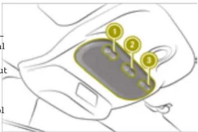
text_image
Diagram of a car interior with numbered labels pointing to specific areas, likely indicating positioning or status.▶ Press switch ① to activate or deactivate the left-hand reading lamp.
▶ Move switch ② to the desired position:
• interior lighting switched on
• interior lighting controlled automatically
• interior lighting switched off
▶ Press switch ③ to activate or deactivate the right-hand reading lamp.
Adjusting the ambient lighting (color display)
On-board computer with color display: the ambient lighting is set in the on-board puter (page 88).
Using the windshield wiper
Switching on the windshield wiper
Please note
! Do not operate the windshield wipers when the windshield is dry, as this could damage the wiper blades. Moreover, dust that has collected on the windshield can scratch the glass if wiping takes place when the windshield is dry.
If it is necessary to switch on the wind-shield wipers in dry weather conditions, always use washer fluid when operating the windshield wipers.
! Vehicles with a rain sensor: if the windshield becomes dirty in dry weather conditions, the windshield wipers may be activated inadvertently. This could then damage the windshield wiper blades or scratch the windshield.
For this reason, you should always switch off the windshield wipers in dry weather.
! Make sure that the front windshield wipers are free of ice. The wiper motor could otherwise overheat.
Wiper blades are subject to wear and tear. smart recommends replacing the wiper blades twice a year. Worn or damaged wiper blades cause smearing on the windshield. On vehicles with a rain sensor, malfunctions are then possible.
Switching continuous wipe on and off
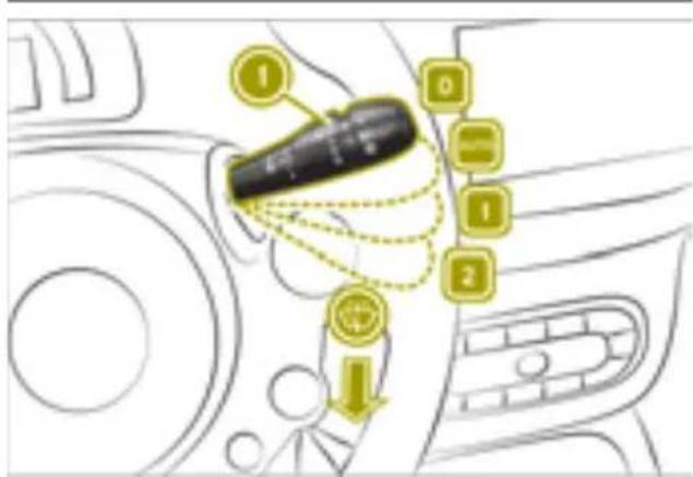
text_image
Diagram showing car interior with labeled buttons and directional arrows, likely indicating navigation or system states.① Control for wipe frequency
0 Continuous wipe, off
Automatic wipe
1 Continuous wipe, slow
2 Continuous wipe, fast
Wiping with washer fluid
The ignition must be switched on in order operate the windshield wiper.
▶ Press the combination switch down or up to the desired position.
Automatic wipe (vehicles with rain sensor)
The rain sensor is only an aid. The driver responsible for ensuring good visibility at all times.
▶ Press the combination switch to the position. In automatic wipe mode, the appropriate wiping frequency is set according to the intensity of the rain.
▶ Use control ① to set the wipe frequency.
Switching on intermittent wiping
▶ Press the combination switch to the position.
▶ Use control ① to set the wipe frequency.

Wiping with washer fluid
▶ Pull the combination switch in the direction of arrow .
Switching the rear window wiper on and off (smart fortwo coupe)
natural_image
Diagram of a car dashboard with steering wheel and gear, showing a close-up of the dashboard's key (no text or symbols present)To operate the rear window wiper, the ignition must be switched on.
▶ Turn the outer control on the combination switch to the desired position:
• 0 Rear window wiper off
- Rear window wiper on
- Wipes with washer fluid
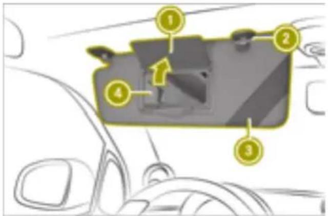
text_image
Diagram of a car interior with numbered components, likely indicating parts of the dashboard or camera module.① Mirror cover
② Bracket
③ Retaining strap
④ Vanity mirror
▶ Fold the sun visor down.
▶ Pull the sun visor out of retainer ②.
▶ Fold the sun visor to one side
Switching the rear window wiper on and off when in reverse gear (smart fortwo coupe)
You can switch the "Automatic rear window wiper when reversing" setting on or off in the smart Media-System. The rear window wiper operates automatically for a short while when the ignition and the windshield wiper are switched on and reverse gear is engaged.
▶ In the smart Media-System, select Vehicle
Settings > Auto rear wipe with reverse gear.
The selected setting is highlighted.
▶ Confirm the setting with
Folding the sun visor to the side

WARNING
If the mirror cover of the vanity mirror is folded up when the vehicle is in motion, you could be blinded by incident light. There is a risk of an accident.
Always keep the mirror cover folded down while driving.
Locking and unlocking the doors from the inside
Using the door handle to unlock the door

natural_image
Line drawing of a car interior showing dashboard, steering wheel, and keyway (no text or symbols)
text_image
Diagram of a car interior with labeled parts and a lock icon highlighting the door key▶ To lock: press button ①.
When the doors are locked, indicator lamp ② lights up.
▶ To unlock: press button ①.
▶ Pull door handle ①.
If the vehicle has previously been locked with the SmartKey, opening a door from the inside will trigger the anti-theft alarm system. To disable the alarm, switch on the ignition.
Centrally locking and unlocking the vehicle from the inside

WARNING
If children are left unsupervised in the vehicle, they could:
- open the doors, thus endangering other people or road users.
• get out and disrupt traffic.
• operate the vehicle's equipment.
Additionally, children could set the vehicle in motion if, for example, they:
• release the parking brake.
- shifting the automatic transmission out of park position P
- Start the engine.
There is a risk of an accident and injury. When leaving the vehicle, always take the SmartKey with you and lock the vehicle.
Never leave children or animals unattended in the vehicle. Always keep the Smart-Key out of reach of children.
Activating and deactivating the automatic locking feature
The activated automatic locking feature locks the vehicle automatically when the ignition is switched on and the vehicle is moving.
▶ When the engine is running, press and hold button ① for five seconds until a sounds.
When the automatic locking function is activated, the locking mechanism engages audibly when you pull away. When the automatic locking function is deactivated, no sound occurs.
Understanding the reversing feature
Vehicles with automatic operation: the side windows are equipped with an automatic reversing feature. If a solid object blocks of restricts a side window from closing during automatic operation, the side window opens again automatically. During the manual closing process, the side window only opens again automatically after the corresponding switch is released. The automatic reversing feature is only an aid. The driver is responsible for operating the side windows safely.

WARNING
The reversing feature does not react:
- to soft, light and thin objects, e.g. small fingers
- while resetting
This means that the reversing feature cannot prevent someone being trapped in these situations. There is a risk of injury. Make sure that no body parts are in close proximity during the closing procedure. If someone becomes trapped, press the switch to open the side window again.
poses an increased risk of injury or even fatal injury.
Make sure that no parts of the body are in the closing area. To stop the closing process, release the switch or push the switch again to reopen the side window.
Vehicles with automatic operation: the switches for both side windows are located on the driver's door. There is also a switch for the front-passenger window on the front-passenger door. The switch on the driver's door takes precedence.
Opening and closing the windows
Please note

WARNING
While closing the side windows, body parts in the closing area could become trapped. There is a risk of injury.
When closing make sure that no parts of the body are in the closing area. If somebody becomes trapped, release the switch or press the switch to open the side window again.

WARNING
If children operate the side windows they could become trapped, particularly if they are left unsupervised. There is a risk of injury.
When leaving the vehicle, always take the SmartKey with you and lock the vehicle. Never leave children unsupervised in the vehicle.

WARNING
If you close a side window again immedi- Vehicles without automatic operation
ately after it has been blocked or reset, the ▶ To open: press the switch.
side window closes with increased or max-▶ To close: pull the switch.
imum force. The reversing feature is then not active. Parts of the body could be trapped in the closing area in the process. This
Opening and closing the windows
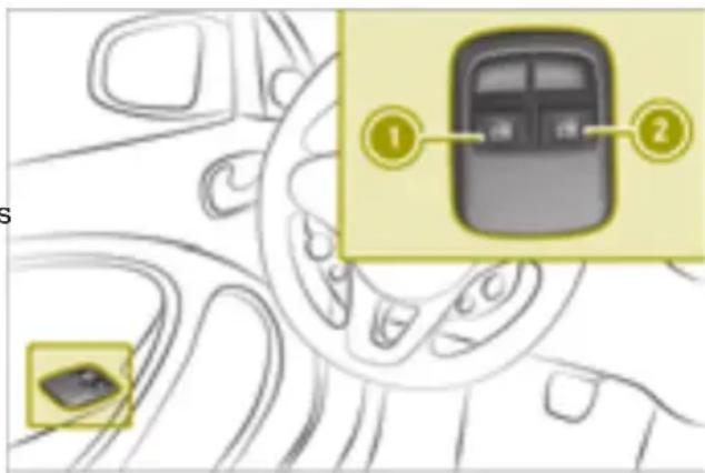
text_image
Diagram showing car interior with labeled parts and a highlighted device, likely illustrating vehicle control or navigation.^2 Vehicles with automatic operation
① Left side window
② Right side window
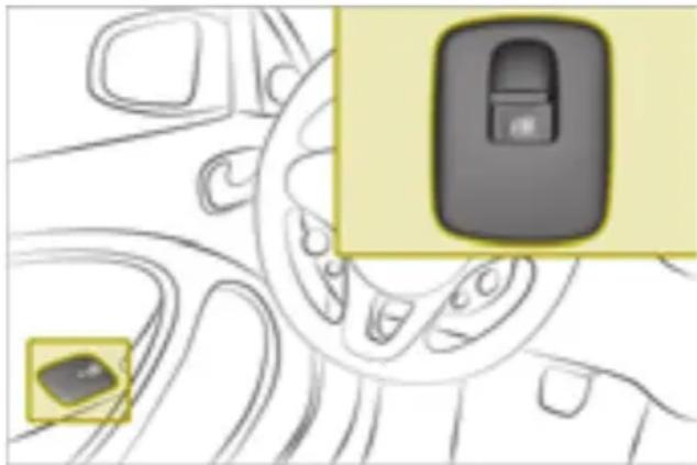
natural_image
Diagram of a car interior showing steering wheel and dashboard with two highlighted car slots (no text or symbols)Opening and closing windows fully in automatic mode
Vehicles with automatic operation:
▶ To open the windows fully, press the switch beyond the point of resistance release it.
▶ To close the windows fully, pull the switches beyond the point of resistance and release it.
▶ To stop automatic operation, press the switch again.
! Make sure that objects are not stacked too high in the cargo compartment. They may be damaged when the rear soft top is opened or closed.
The procedure for removing, installing and stowing the side bars is described below. The QR code is a link to a video clip that demon-
text_image
QR code image containing encoded data, no visible human-readable textUsing the soft top (smart fortwo cabrio)
Please note

WARNING
During opening and closing of the folding top or rear soft top, body parts may become trapped for example, by the roof mechanical system. There is a risk of injury.
Ensure that no parts of the body are in the immediate vicinity of moving parts during the closing or opening process. Release the switch immediately if somebody becomes trapped.
! When transporting long objects in the vehicle interior when the folding top is closed, make sure that the objects do not push against the folding top.
When transporting objects that protrude out of the rear of the vehicle, make sure that the objects do not rest on the rear s top latch (bracket). Make sure that no sharp edged parts come into contact with the soft top or the rear window during loading.
Do not place flatly distributed loads with weight of more than 75 kg on the folded down rear soft top.
Make sure that the high-mounted brake lamp is not covered.
Opening and closing the soft top
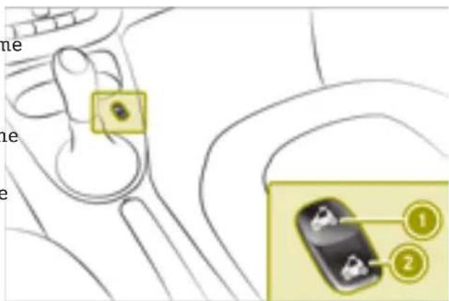
text_image
ne ne ne ① ②To open or close the soft top, the ignition must be switched on.
▶ To open: press the switch to position ② until the soft top is in the desired position. Press switch ② again to fully open the soft top.
▶ To close: press the switch to position ① until the soft top is in the desired position. It is possible to open or close the soft top while driving up to the maximum design speed. In poor weather and at high speeds, it is possible that electric locking when closing is not reliable. If this is the case you must reduce the speed and, if necessary, press the switch again to close the soft top.
! Do not obstruct the latch openings of the soft top system. Stow the side bars only in the designated stowage well of the tail-gate.
Opening the soft top (using the Smart-Key)
▶ Press and hold the 📄 button on the SmartKey.
Removing the side bars
- Open the soft top - Open the doors and tailgate.
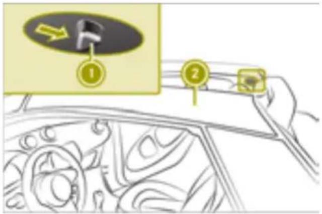
text_image
Diagram showing a car dashboard with labeled parts and directional arrow indicator- To release: slide lever ① back. The side bar is unlocked. - Push lever ① back again and remove side bars ②.
Stowing the side bars

WARNING
If you transport the side bars without securing them, they may be thrown around in the event of an accident, braking or sudden changes in direction. There is a risk of injury.
Always stow the side bars in the designated stowage well and close the stowage well lid.
Please note:
- only use the stowage space to store the side bars - always place both side bars in the stowage space
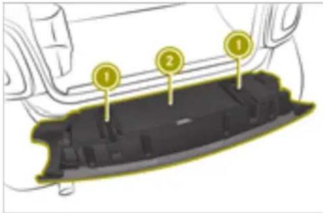
text_image
Diagram of a car interior showing labeled components with numbered calloutsObserve the notice on the stowage well.
- Release fastening straps ① on the stowage space and guide the locking mechanism with your hand until the fastening straps are released. - Open cover ②. - Store the side bars as shown (observe markings L and R on the side bars and the stowage compartment for the left and right side bars):
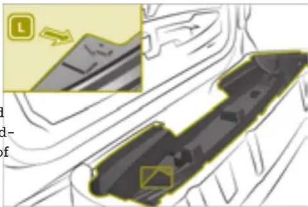
text_image
Diagram showing a car interior with a highlighted vehicle component and directional arrow, accompanied by partial text labels.When the soft top is folded down, theft of the side bars is possible. Therefore, remove the side bars and stow them in the cargo compartment or close the soft top.
! If you load the stowage space it could be damaged.
Never stow heavy objects on the stowage space or sit on it.
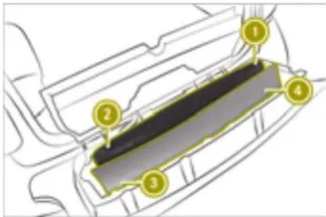
text_image
Technical diagram of a vehicle interior with numbered components labeled 1 to 4① Side bar, front left
② Side bar, rear left
③ Side bar, front right
④ Side bar, rear right

text_image
Diagram showing a car's internal component with numbered parts, including highlighted areas and a magnified detail view.▶ Close the cover. The cover must audibly engage.
- Secure both fastening straps with tensioner ① on rear detent ②. The red surfaces at the side must no longer be visible. An audible click can be heard upon engaging.
▶ Close the tailgate.
▶ If the tailgate does not close properly, check if the side bars have been stored as specified.
Mounting the side bars

WARNING
If the side bars are incorrectly mounted they may become loose during the journey and endanger other road users. There is a risk of an accident and injury. Mount the side bars as described.
▶ Open the doors and tailgate.
▶ Release the fastening straps on the stow-age space and guide the locking mechanism with your hand until the fastening straps are released.
▶ Open the cover.
▶ Remove the side bars.
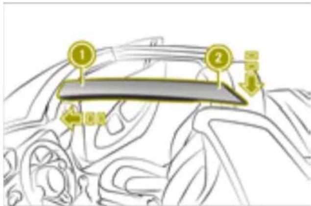
text_image
Diagram of a car interior with numbered components and directional arrows indicating movement or navigation▶ Insert the side bar from the stowage compartment marked L on the left side at front end ①.
▶ Press down rear end of side bar ② until engages twice.
▶ Install the side bar from the stowage compartment marked R on the right-hand side
Closing the stowage well without the side bars
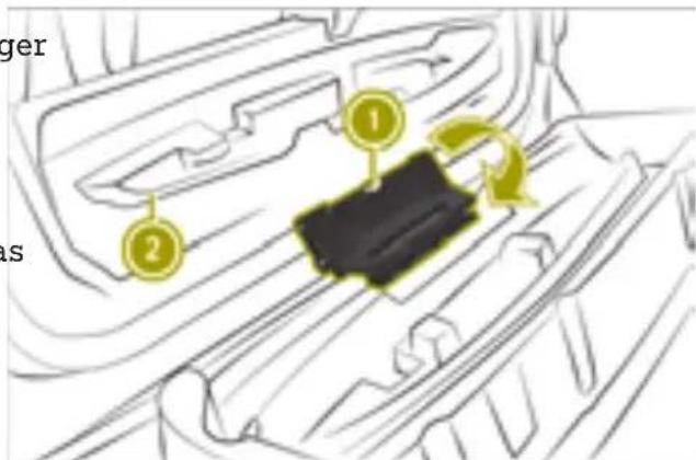
text_image
ger 1 2▶ Move folding mechanism ① in the direction of the arrow.
▶ Close cover ②.
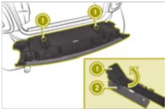
text_image
Diagram showing a car interior with numbered components and a close-up of the component being cut, labeled with numbers 1 and 2.- Secure both fastening straps with tensioner ① on front detent ②.
The red surfaces at the side must no long be visible. An audible click can be heard upon engaging.
▶ Close the tailgate.
Installing and removing the wind screen (smart fortwo cabrio)
Installing the wind screen
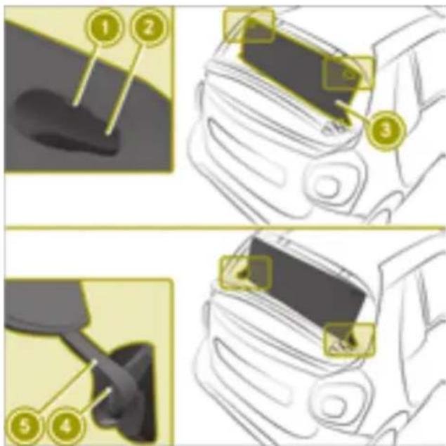
text_image
Diagram illustrating car seatbelting steps with numbered instructions for adjusting seatbelt.▶ Open the soft top completely.
▶ Attach recesses ① of wind screen ③ on to hooks ② on the roll bar.
▶ Attach loops ⑤ on to hooks ④ in the side paneling.
Removing the wind screen
▶ Unhook loops ⑤ from hooks ④ in the side paneling.
▶ Unhook recesses ① from hooks ② on the roll bar.
Operating the climate control system
Useful information
The climate control system is only available when the ignition is switched on.
If the climate control system is deactivated, the air supply and circulation are switched off. The windows could fog up. You should therefore switch off the climate control system for brief periods only.
In air-recirculation mode, only the air inside the vehicle is recirculated and no fresh air is introduced. This is useful in a tunnel or when there are unpleasant odors outside the vehicle. In air-recirculation mode, the windows may fog up more quickly, particularly when the outside temperature is low. Therefore, switch on air-recirculation mode only briefly.
The integrated filter in the climate control system keeps out most particles of dust as well as pollen. The filter reduces the amount of air supplied to the vehicle interior. For this reason, you should always observe the interval for replacing the filter.
Operating the automatic climate control
Switching the automatic climate control system on and off
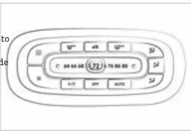
text_image
to de C 64668 72 756680 C A/10 OFF AUTOThe ignition must be switched on in order to operate the blower. The engine must be running in order to operate all the functions of the automatic climate control system.
To switch on: press the ☐ and n-☐ A/C button. of The indicator lamp below ☐ lights up when the function is activated.
▶ To switch on: press the AUTO button. The indicator lamps below AUTO and A/C light up.
In damp weather switch off the "Cooling with air dehumidification" function only briefly. Otherwise the windows will fog up faster.
▶ To switch off: press the OFF button. The indicator lamp below OFF lights up.
Defrosting the windshield
Setting the temperature
▶ Move the slider in small increments to the left or right.
In automatic mode, the set temperature is maintained at a constant level. The air distribution and blower speed are regulated automatically.
▶ Press the MAX button. The indicator lamp above MAX lights up when the windshield is being defrosted.
Use this setting only until the windshield is clear again.
Switching the air distribution on and off
▶ Press one or more of the 📞, 📞, 📞 buttons.
• Defroster vents
• Center and side air vents
- Footwell vents
Defrosting the rear window
When the rear window defroster is activated, the exterior mirrors are also heated.
▶ Press the REAR button.
The indicator lamp above 📄REAR lights up when the rear window defroster is activated.
Use this setting only until the rear window is clear again.
Increasing the blower speed
▶ Press the 🎩 button.
Decreasing the blower speed
▶ Press the ☉ button.
Activating/deactivating air-recirculation mode
▶ Press the 📄 button. The indicator lamp above 📄 lights up when air-recirculation mode is activated.
Switching "Cooling with air dehumidification" on or off
The "Cooling with air dehumidification" function cools and dehumidifies the air inside the vehicle during warm weather. The engine must be running in order to "Cooling with air dehumidification".
Drying windows that are fogged up on the inside
▶ Press the A/C button.
▶ Press the AUTO button.
▶ If the windows are still fogged up, press the MAX button.
Use this setting only until the windows are clear again.
Drying windows that are fogged up on the outside
▶ Switch on the windshield wipers.
▶ Press the MAX button.
Use this setting only until the windows are clear again.
Setting the pre-entry climate control at departure time using the on-board computer
The "Pre-entry climate control at departure time" function" heats or cools the vehicle
interior before the scheduled departure time.
The climate control runs until approx.
10 minutes after the set departure time.
The vehicle must be connected to the charge in order to activate pre-entry climate control. The battery charge and the charge output of the high-voltage battery must be sufficient.
If pre-entry climate control cannot be operated, a display message is shown in the onboard computer.

WARNING
If you spray cleaning products or disinfectant into the ventilation system of the vehicle, this could ignite. There is a risk of fire.
Never spray these or any other substances into the ventilation system. Always have work on the ventilation system carried out at a qualified specialist workshop.
▶ Call up Pre-ent. Clim. Ctrl. & Charge in the on-board computer.
▶ Press OK.
▶ Select one of the following settings:
- no Preselection
The pre-entry climate control is deactivated.
- Two stored departure times
Departure time > selectActivate to activate the stored departure time.
Departure time > select change to change the settings of a stored departure time.
▶ Set the value
If i instant charging is selected, the high-voltage battery is charged regardless of the cost information. A part of the charging may not be conducted until one to two hours before the departure time, in order for temperature control of the high-voltage battery to be carried out for the intended departure time.
Keep the following rules in mind for optimal climate control:
- Keep the air slots between the service cover and windshield clear of blockages.
- Do not cover the vents or ventilation grilles in the vehicle interior.
- Open the air vents fully.
Opening and closing the air vents

text_image
Diagram showing two circular components with labeled parts, one containing a molecular structure and the other a solid black surface.▶ To open: turn vent 1 outwards.
▶ To close: turn vent 2 inwards.
Directing the air vents
▶ Turn the air vents upwards, downwards, to the left or to the right as desired.
Setting the air vents
Please note

WARNING
Very hot or very cold air can flow from the air vents. This could result in burns or frostbite in the immediate vicinity of the air vents. There is a risk of injury.
Make sure that all vehicle occupants always maintain a sufficient distance to the air outlets. If necessary, redirect the airflow to another area of the vehicle interior.
Activating/deactivating the seat heating and steering wheel heating

WARNING
Repeatedly switching on the seat heating can cause the seat cushion, the backrest pad and parts of the steering wheel to become very hot. The health of persons
with limited temperature sensitivity or a limited ability to react to higher temperatures may be affected or they may even suffer burn-like injuries. There is a risk of injury.
Therefore, do not switch the seat heating on repeatedly.
! Heat accumulation can occur if the seat heating is switched on and there are objects or underlays placed on the seats, e.g. seat cushions or child seats.
This can lead to damage to the seat surface.
Make sure that no objects or underlays are placed on the seats when the seat heating is switched on.
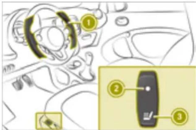
text_image
Diagram showing car interior and dashboard with numbered annotations indicating key componentsIn addition, flammable materials can ignite if:
- the hot cigarette lighter falls - a child holds the hot cigarette lighter to objects, for example
There is a risk of fire and injury.
Always hold the cigarette lighter by the knob. Always make sure that the cigarette lighter is out of reach of children. Never leave children unsupervised in the vehicle.
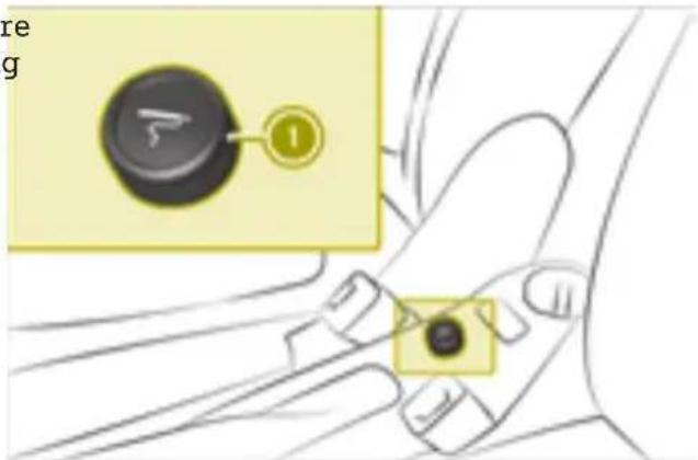
text_image
re g 1The cigarette lighter only works when the ignition is switched on.
▶ Press cigarette lighter ①.
The seat heating only works when the igni- When cigarette lighter ① is hot, it pops up tion is switched on. Vehicles with the Winter automatically. package are additionally equipped with the "Steering wheel heating"① function.
▶ Press button ③.
Indicator lamp ② lights up when seat heating is activated.
Vehicles with the Winter package: steering wheel heating ① is also switched on when the driver's seat heating is activated.
Using the ash tray
! The cup holder in the center console is not heat resistant. Before placing lit cigarettes in the ashtray, make sure that the ashtray is fully inserted in the cup holder. Make sure that lit cigarettes do not fall into the cup holder.
Otherwise, the cup holder could be damaged.
Using the accessories
Using the cigarette lighter

WARNING
You can burn yourself if you touch the hot heating element or the socket of the cigarette lighter.
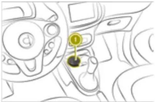
natural_image
Interior view of a car dashboard with steering wheel and keyhole (no text or symbols visible)▶ To open: lift up cover ①.
▶ To close: push down cover ①.
▶ To remove: pull the ashtray up and out.
▶ To insert: insert the ashtray into the cup holder.
Using the 12 V socket
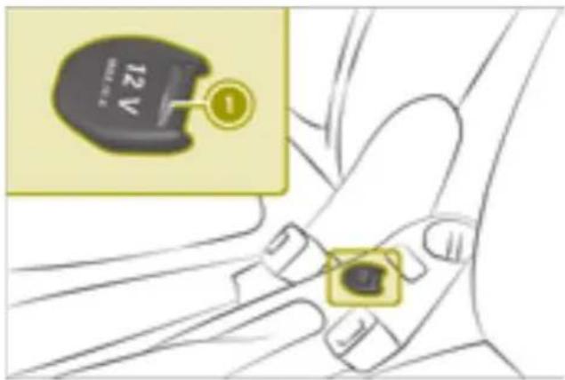
text_image
12V ①▶ Turn the SmartKey to position 1 in the ignition lock.
▶ Lift up the cover of socket ①.
▶ Connect device.
The socket can be used for accessories up to a maximum draw of 120 W (15 A).
If you use the socket for very long periods when the engine is switched off, the 12 V battery may discharge.
vehicle is jeopardized. There is a risk of an accident.
Make sure that all objects in the vehicle are stowed correctly, and that they cannot enter the driver's footwell. Install the floormats securely and as specified in order to ensure sufficient clearance for the pedals. Do not use loose floormats and do not place floormats on top of one another.
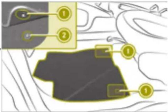
text_image
Diagram showing a highlighted section with numbered annotations and a silhouette of a person's head, likely illustrating a technical or educational concept.▶ Slide the driver's seat backward.
▶ To install: press securing knobs ① onto retainers ②.
▶ To remove: release securing knobs ① from retainers ②.
Installing and removing the floormats

WARNING
Objects in the driver's footwell can restrict the pedal travel or obstruct a depressed pedal. The operating and road safety of the
Parking
Please note

WARNING
The automatic transmission switches to neutral position N when you switch off the engine. The vehicle may roll away. There is a risk of an accident.
Before switching off the engine, always switch to parking position P. Prevent the parked vehicle from rolling away by applying the parking brake.
! Always secure the vehicle correctly against rolling away. Otherwise, the vehicle or its drivetrain could be damaged.
The rear view camera is a visual parking and maneuvering aid. It shows the area behind the vehicle with guide lines in the rear-view mirror. The rear view camera is activated automatically when the vehicle is backing up.
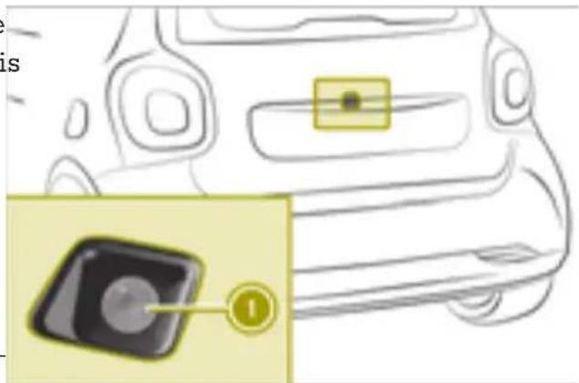
natural_image
Line drawing of a car front view with a highlighted camera icon (no text or symbols)Switching off the engine
▶ Apply the parking brake.
▶ Shift the transmission to position P.
▶ Turn the SmartKey to position 0 in the ignition lock and remove it.
▶ On steep uphill or downhill gradients, turn the front wheels towards the curb.
Rear view camera ① is located above the license plate in the tailgate.
The area behind the vehicle is displayed as a mirror image, as in the rear-view mirror.
The rear view camera might show a distorted view of obstacles or show them incorrectly or not at all if:
- the obstacle is very close to the rear n bumper.
- the obstacle is underneath the rear bumper.
- the obstacle is close to the tailgate handle.
- the rear view camera is covered by additional accessories, e.g. a bicycle rack.
Using the rear view camera
! Pay attention to people and obstacles when maneuvering or parking the vehicle. The driver is responsible in these situations.
! If the rear of your vehicle is damaged, consult a qualified specialist workshop and have the rear view camera checked.
! Objects that are not at ground level appear further away than they actually are, for example:
• the bumper of the vehicle parked behind
• the drawbar of a trailer
• the ball coupling of a trailer tow hitch cle.
• the tail-end of a truck
- slanted posts
Only use the image from the rear view camera as a guide. You may otherwise damage your vehicle and/or the object.
The function of the rear view camera might be limited:
- if the tailgate is open
- if there is snow or heavy rain
- in the dark
- if a very bright light outshines the camera
- if there is fluorescent light, e.g. from fluorescent lamps or LED lighting
- if there is a rapid change of temperature
- if the camera lens is dirty
Guide lines in different colors show the distance of obstacles from the rear of the vehi-
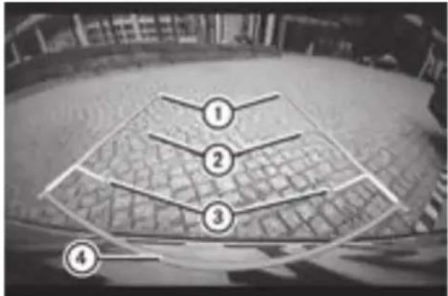
text_image
Diagram with numbered labels pointing to a grid-patterned surface, likely illustrating a technical or engineering concept.① Vehicle width including exterior mirrors
② Green: approx. 59 in (1.50 m)
③ Yellow: approx. 27 in (0.7 m)
④ Red: approx.12 in (0.3 m)
The distance specifications only apply to objects that are at ground level.
Locking the vehicle

WARNING
If children are left unsupervised in the vehicle, they could:
- open the doors, thus endangering other people or road users.
• get out and disrupt traffic.
• operate the vehicle's equipment.
Additionally, children could set the vehicle in motion if, for example, they:
- release the parking brake.
- shift the transmission out of park position P
- start the vehicle's drive system.
There is a risk of an accident and injury.
When leaving the vehicle, always take the SmartKey with you and lock the vehicle.
Never leave children or animals unattended in the vehicle. Always keep the Smart-Key out of reach of children.
▶ Press the 🔒 button on the SmartKey. The turn signals flash twice.
Locking is confirmed by an audible signal.
Arming and disarming the anti-theft alarm system
Useful information
The immobilizer prevents the vehicle from being started without the correct SmartKey. It is switched on and off automatically.
The anti-theft alarm system triggers a visual and audible alarm if a door, the tailgate or the service cover is opened.
The alarm is not switched off, even if, for example, you close the open door that has triggered it.
Arming
▶ Close the doors.
▶ Close the tailgate.
▶ Close the service cover.
▶ Press the 🔒 button on the SmartKey. The alarm system is armed after approximately 30 seconds.
Disarming and switching off the alarm
▶ Press the 📤 button on the SmartKey.
Overview of the on-board computer
Please note

WARNING
If you operate information systems and communication equipment integrated in the vehicle when driving, you may be distracted from the traffic situation. You could also lose control of the vehicle. There is a risk of an accident.
Only operate this equipment when the traffic situation permits. If you are not sure that this is possible, park the vehicle paying attention to traffic conditions and operate the equipment when the vehicle is stationary.

WARNING
If the instrument cluster has failed or mal functioned, you may not recognize function restrictions in systems relevant to safety. The operating safety of your vehicle may be impaired. There is a risk of an accident.
Drive on carefully. Have the vehicle checked at a qualified specialist workshop immediately.
If the operating safety of your vehicle is impaired, you must park the vehicle safely soon as possible. Consult a qualified specialist workshop.
The outside temperature is displayed on the far right in the top bar. Drivers must pay special attention to road conditions when temperatures are around freezing point. Changes in the outside temperature are displayed after a short delay.
After opening the door, the on-board computer is activated for approximately 15 minutes. To permanently activate the on-board computer, the ignition must be switched on.
Color display overview
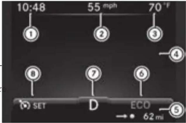
text_image
10:48 55 mph 70°F ① ② ③ ④ ⑥ ⑦ ⑧ SET D ECO → 62 mi ⑤① Time
② Digital Speedometer
③ Outside temperature display
④ Display field for display messages, menus and lists
⑤ ECO mode
⑥ Remaining range
⑦ Transmission display
⑧ Cruise control
Calling up displays
Calling up displays (color display)
Calling up displays
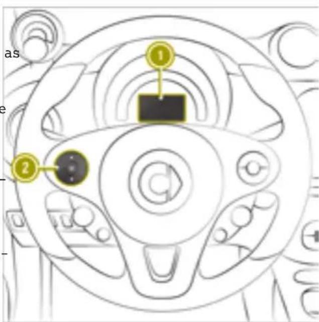
text_image
as 1 2① Color display
② Left control panel
▶ Briefly press ▲ or ▼ on left control If the ignition remains switched off for lon-panel ②, to scroll forward or back. gger than four hours, then start values in
▶ Press and hold ▲ or ▼ on left control the instrument cluster are reset.
panel ②, to directly call up the distance display.
The following displays can be called up one after another:
- Distance
- Trip computerFFoomSStart
- Trip computerFFoomRReset
• eco score from Start
• Fuel consumption bar chart - Energy Flow
• Pre-ent. Clim. Ctrl & Charge - Messages and Service
- Settings
• Digital Speedometer
Distance display
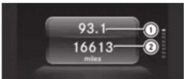
bar
| Value | Label | |---|---| | 93.1 | ① | | 16613 | ② |① Trip odometer
② Odometer
Trip computer display
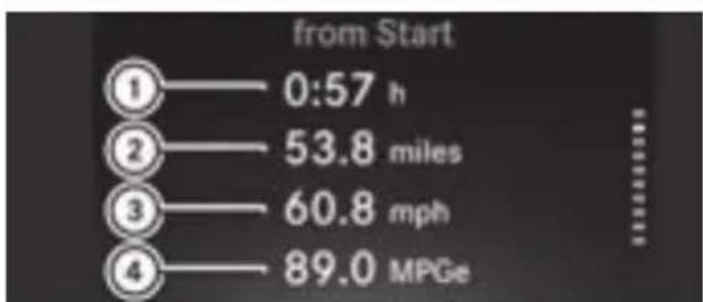
text_image
from Start ①—0:57 h ②—53.8 miles ③—60.8 mph ④—89.0 MPGe① Elapsed time
② Distance
③ Average speed
④ Average energy consumption
The data in the from Start menu refers to the start of the journey, whilst the data in the from Reset menu refers to the last time the submenu was reset.
eco score display
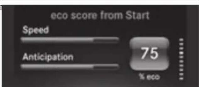
text_image
eco score from Start Speed Anticipation 75 % ecoThe eco score display provides feedback on how economical the driver's driving behavior is (▷ page 57).
If the ignition remains switched off for longer than four hours, the eco score display will be automatically reset.
When the eco score display is reset, the from Start trip computer in the smart Media-System and the eco score display are also reset in the smart Media-System.
Fuel consumption bar chart display
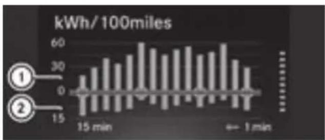
bar
| Time | Energy Consumption (kWh/100miles) | |---|---| | 15 min | 20 | | 16 min | 30 | | 17 min | 40 | | 18 min | 50 | | 19 min | 60 | | 20 min | 55 | | 21 min | 50 | | 22 min | 45 | | 23 min | 40 | | 24 min | 35 | | 25 min | 30 | | 26 min | 25 | | 27 min | 20 | | 28 min | 15 | The chart displays the energy consumption values for two distinct categories (① and ②) at each time point. The y-axis represents energy consumption in kWh per 100 miles. There is no explicit numerical data provided in the image.① Energy consumption
② Recuperation
The display shows the average energy consumption and recuperation over the previous 15 minutes.
Energy flow display
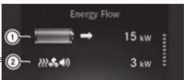
text_image
Energy Flow ① → 15 kw ② → 3 kw① Total output
② Output for electrical consumers
The total output shows the driver the sum of the energy currently flowing from the battery. The color of the battery shows whether energy is being consumed or recuperated:
- Battery symbol is orange: energy is being consumed.
- Battery symbol is green: energy is being recuperated.
- Battery symbol is gray: energy consumption and recuperation are equal or both a 0 kW.
Messages and service display
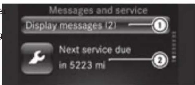
text_image
Messages and service Display messages (2) ① Next service due in 5223 mi ②① Message memory
② Next service due date
The output for electrical consumers shows the driver what output is needed to operate electrical consumers such as climate control systems or the radio. A greater range is achieved if the value is kept as low as possible. 📄 indicates a minor service. ✗ indi-
Pre-entry climate control and charging display
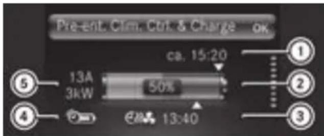
text_image
Present. Clm. Ctrl & Charge OK ca. 15:20 13A 3kW 50% 28 13:40 ① ② ③ ④ ⑤① Time of the full charge
② Condition of charge of the battery
③ Departure time
④ Smart-Charging
⑤ Charge current and charge output
The display shows the number of display messages in the message memory and the next service due date.
indicates a minor service. indicates a major service.
To show the display messages, the ignition must be switched on.
▶ Press OK to scroll through the display messages.
Current information on the type of service can be obtained at a smart center or a qualified specialist workshop.
Digital speedometer display
The display shows the digital speedometer. The digital speedometer in the header is h den.
Setting values
eSetting values (color display)
Setting values
An arrow underneath the battery indicates the condition of charge of the battery at the departure time. The condition of charge and the time of complete charge are only predicted approximately. The moment at which charging is completed cannot be displayed when Smart-Charging is activated.
Information on the "Pre-entry climate control at departure time" function page 79).
text_image
Settings back Time OK Display Ambient lighting▶ Press ▲ or ▼ to scroll to Settings.
▶ Press ▲ or ▼ to scroll to the desired menu.
▶ Press ▲ or ▼ to set the desired data.
▶ Press OK to confirm.
Resetting values
▶ Press OK.
▶ Select YES and press OK to confirm.
Setting the time
▶ Select Settings > Time > Set the Time.
▶ Set values
Vehicles with smart Media-System: the time and time format are set in the smart(▷ page 143). Media-System.
Setting the time format
▶ Select Settings > Time > Time Format 12/24.
▶ Set the value
Adjusting the instrument cluster lighting
▶ Select Settings > Display > Brightness Display/Switches.
▶ Set the value
Displaying the digital speedometer in the header
▶ Select Settings > Display > Digital Speedometer.
▶ Select the DDisplaySSpeedometer function.
The digital speedometer is displayed in the header.
Setting the unit for speed in the digital speedometer
▶ Select Settings > Display > Digital Speedometer > Udmit.
▶ Set the value
The following values are set:
• Digital speedometer display
• Digital speedometer in the header
Setting the unit of measurement for distance
▶ Select Settings > Display > Units of Distance.
▶ Set the value
Setting the temperature unit
▶ Select Settings > Display > Units of Temperature.
▶ Set the value
Starting the tire pressure monitor
▶ Select Settings TiFereresessureMonitor.
Information on the tire pressure monitor (▷ page 143).
Switching the ambient lighting on/off
▶ Select Settings > Ambient Lighting > On.
Setting the brightness of the ambient lighting
▶ Select Settings > Ambient Lighting > Brightness.
▶ Set the value
Setting the language
▶ Select Settings > Language (Language).
▶ Set the value
Operating and setting the smart Audio-System
smart Audio-System overview

WARNING
If you operate information systems and communication equipment integrated in the vehicle when driving, you may be distracted from the traffic situation. You could also lose control of the vehicle. There is a risk of an accident.
Only operate this equipment when the traffic situation permits. If you are not sure that this is possible, park the vehicle paying attention to traffic conditions and operate the equipment when the vehicle is stationary.
⑫ RADIO Switches on the radio and selects the waveband.
⑬ External audio equipment (AUX jack)
⑭ Volume control, ⏻ button
⑮ TEXT Sets the radio text
Operating and setting the smart Audio-System
To switch on or off: press
▶ To scroll through menus: turn control ⑥
▶ To select menu options: turn control ⑥ and press the Ⓞ button.
▶ To navigate to the next-highest folders: press the ← button.
▶ To set values: turn control ⑥ and press Ⓞ button.
▶ To increase or decrease the volume: turn control ⑭.
You must observe the legal requirements for the country in which you are currently driving when operating the smart Audio-System.
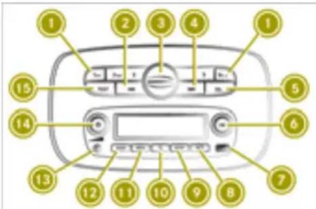
text_image
Diagram of a car air conditioner front panel with numbered labels pointing to the control panel.① Number keys 1 - 6
② Previous station or track
③ USB1 port and bracket connection for mobile phone with smart cross connect app
④ ▶▶▶ Next station or track
⑤ Goes back one menu level higher
⑥ Control for menu selection and station list, Ⓞ button
⑦ USB2 connection
⑧ TEL) Telephone menu, to accept or reject calls
⑨ SETUP System settings
⑩ Mute
⑪ MEDIA Plays back media from external data carriers
Using external devices
Useful information
You can connect the following external devices:
- USB devices, iPod ^ and MP3 players (USB port)
- External audio equipment (AUX jack)
- Bluetooth ^ devices, such as mobile phones
Removing the cover of the USB1 connection and securing it
text_image
er 1 2Removing the cover
▶ Turn handle ① on the cover counterclockwise.
▶ Press on marking ②.
▶ Remove the cover.
Fastening the cover
▶ Place cover in position ②.
▶ Turn the cover clockwise using handle ①.
Using the smartphone bracket
Useful information
i Operating smartphones in the smartphone bracket is permitted exclusively in connection with the smart cross connect App.
The smartphone bracket keeps your mobile phone secured in the vehicle. In order to use the smart cross connect App, rotate the mobile phone to landscape mode.
You can use the USB port behind the smartphone bracket on the left to charge your mobile phone during the journey.
The smartphone bracket is suitable for mobile phones with the following dimensions:
• Thickness: 0.24 - 0.39 in (6 - 10 mm)
- Width: 2.17 - 3.23 in (55 - 82 mm)
• Length: 4.72 - 6.38 in (120 - 162 mm)
Further information is available from any smart center.
Installing the smartphone bracket
▶ Remove the cover from the USB1 port.
▶ Connect the smartphone bracket to USB1 and turn the fastener to clockwise.
▶ Remove the cover from the USB1 port.
▶ Connect the smartphone bracket to USB1 and turn the fastener to clockwise.
Inserting and removing the mobile phone
▶ To insert: press the right-hand raised but-ton on the bottom edge of the smartphone bracket.
The upper tensioning arm opens.
▶ If necessary, press the left-hand button on the bottom edge of the smartphone bracket.
The tensioning arms on the side open.
▶ Set the mobile phone in the smartphone bracket.
▶ If necessary, press the tensioning arms on the side together to set them to the size of the mobile phone.
▶ Press down the upper tensioning arms to secure the mobile phone.
▶ To remove: press the right-hand raised button on the bottom edge of the smartphone bracket.
The upper tensioning arm opens.
▶ Remove the mobile phone from the smartphone bracket.
Operating the smart Audio-System via the mobile phone
You can use the smart cross connect App for iOS and Android to operate the smart Audio-System via a mobile phone.
▶ Download the smart cross connect App from the App Store®(iOS) or Google Play™ (Android) and install it on the mobile phone.
- Connect the mobile phone with the smart Audio-System via Bluetooth®.
▶ Insert the mobile phone into the bracket.
Further information about operating the smart Audio-System via mobile phone can be found in the smart cross connect App user's guide.
Adjusting the system settings
Setting the system language
▶ Press the SETUP button.
▶ Select Language.
The list of languages appears.
▶ Select the language.
Switching the time on or off
e ▶ Press the SETUP button.
▶ Select Clock.
▶ Select ON or OFF.
e ▶ Press the SETUP button.
▶ Select Clock.
▶ Select ON or OFF.
Inserting and removing the mobile phone
Setting the time
▶ Press the SETUP button.
▶ Select Clock.
▶ Select Set Time.
▶ Set the time.
Setting the time format
▶ Press the SETUP button.
▶ Select Clock.
▶ Select Format.
▶ Choose one of the following time formats:
• Am/Pm
• 24hr
Adjusting the audio settings
Adjusting the sound
▶ Press the SETUP button.
▶ Select Audio.
▶ Select Sound.
▶ Select the desired sound settings:
- Bass: adjusts the bass.
- Treble: adjusts the treble.
- Bal.: adjusts the surround sound (balance) to left or right.
Switching Bass Boost on or off (vehicles without JBL sound system)
▶ Press the SETUP button.
▶ Select Audio.
▶ Select Bass Boost.
▶ Select ON or OFF.
Resetting audio settings
▶ Press the SETUP button.
▶ Select Audio.
▶ Select Audio Default.
▶ Select Yes.
Adjusting the volume to the vehicle speed (vehicles without JBL sound system)
▶ Press the SETUP button.
▶ Select Audio.
▶ Select Speed VoT...
▶ Select the desired level.
The higher the level, the higher the volume will be at increasing road speeds.
Listening to the radio
Switching on the radio
▶ Press the ⏻ button.
▶ Press the RADIO button.
The smart Audio-System receives data transmitted via the Radio Data System (RDS
Selecting a waveband
▶ Press the RADIO button repeatedly until the desired waveband appears.
If available, you can switch between the following wavebands:
• FM1
• FM2
• AM
Selecting stations manually
▶ Press the ▶▶ or ◀◀ button to set the desired frequency.
Holding down the ▶▶ or ◀◀ button starts the station search, which stops at the next station with adequate reception.
Setting a station from the station list
▶ Press OK in radio mode.
The station list appears.
▶ Select a station.
▶ Press OK to confirm.
Updating the station list
▶ Press the RADIO button until you hear a tone.
Storing a station
▶ Select a waveband.
▶ Set the station.
▶ Press a number key 1 to 6 until you hear a tone.
The station set for this waveband will be saved at the button you have pressed.
Selecting a stored station
▶ Select a waveband.
▶ Press a number key for the stored station
Switching traffic announcements on/off
▶ Press the SETUP button.
▶ Select Radio.
▶ Select TIA.
▶ Select ON or OFF.
Interrupting a traffic announcement
▶ During a traffic announcement, briefly press ←.
Displaying radio text in FM radio
▶ Press the TEXT button. If radio text is available, it will be displayed.
Using a mobile phone
Connecting a mobile phone
Useful information
The Bluetooth ^® -capable mobile phone must be compatible with the smart Audio-System.
Overview of compatible mobile phones: http://www.smart.com/connect.
To make a call, Bluetooth must be activated on the mobile phone and the smart Audio-System.
Once outside the Bluetooth ^® reception range, the connection is terminated automatically.
To clearly identify a mobile phone, change the device name (see the manufacturer's operating instructions).
Activating Bluetooth ^® on a mobile phone
▶ Activate Bluetooth® on the mobile phone (see the manufacturer's operating instructions).
▶ Search for devices.
Switching on the Bluetooth® function of the smart Audio-System
▶ Press the TEL button.
▶ Turn control ⑥ to Bluetooth and confirm with Ⓞ.
▶ Turn control ⑥ to ON and confirm with OK. The ● dot shows the active setting.
Authorizing a mobile phone on the smart Audio-System
▶ Press the TEL button.
▶ Select Scan devices.
The system searches for available mobile phones and displays them in a list.
▶ Select the mobile phone and confirm with OK.
▶ Do one of the following:
- If a code appears in the smart Audio-System display and on the mobile phone, confirm it on the mobile phone.
- If the code 000000 appears in the smart Audio-System display, enter it and confirm it on the mobile phone.
A maximum of five mobile phones can be authorized. However, only one authorized mobile phone can be connected with Bluetooth ^® at a time.
Loading and updating the telephone book
▶ Press the TEL button.
▶ Select Settings >PBdownload.
▶ If necessary, accept the access confirmation on the mobile phone.
If the mobile phone supports the Bluetooth PBAP (Phone Book Access Profile) profile, the phone book and call lists will be transferred after you connect.
Removing a mobile phone from the list (de-authorizing)
▶ Press the TEL button.
▶ Select Del. device.
Authorized mobile phones are displayed.
▶ Select the mobile phone to be removed.
▶ Select Yes.
After de-authorization, the Bluetooth connection to the mobile phone is no longer established automatically.
Connecting another authorized mobile phone
▶ Activate Bluetooth® on a mobile phone
▶ Press the TEL button.
▶ Select Sell. device.
All authorized mobile phones are displayed. The currently connected mobile phone is indicated by a dot.
▶ Select the desired mobile phone from the list.
Setting the sound
Adjusting the call volume
▶ Press the TEL button.
▶ Select Settings > Volume > Call.
▶ Select the setting.
Switching the smart Audio-System ring-tone on and off
▶ Press the TEL button.
▶ Select Settings > Ringtone.
▶ To switch on: select aCar.
▶ To switch off: select Phone.
Adjusting the ring tone volume
▶ Press the TEL button.
▶ Select Settings > Volume > Ring.
▶ Select the setting.
Using the telephone
Calling a contact from the phone book
To call a contact in the telephone book, the mobile phone telephone book first has to be imported into the smart Audio-System.
▶ Press the TEL button.
▶ Select Phonebook.
▶ Select the contact.
The details for the contact are displayed
▶ Dial the desired phone number.
▶ Press the Ⓞk button.
Dialing a number
▶ Press the TEL button.
▶ Select Dial Number.
An input screen appears.
▶ Enter the number.
▶ Press the Ⓞ button.
▶ Select .
Using call lists to call contacts
To call a contact in a call list, the mobile phone telephone book first has to be imported into the smart Audio-System.
▶ Press the TEL button.
▶ Select Call Lists.
▶ Select Dialed, Received or Missed.
▶ Select an entry from the list.
Calling the last number dialed
▶ Press and hold the TEL button until the call is established.
Accepting a call
▶ Press the TEL button.
Rejecting a call
▶ Press and hold the TEL button until the call is rejected.
Holding and continuing a call
▶ To place a call on hold: select 🔊.
▶ To continue the call: press the Ⓞ button.
Transferring a call to the mobile phone
▶ Select .
▶ To transfer the call back to the smart Audio-System: press OK.
Entering numbers or characters during a call
▶ Select #123.
▶ Enter numbers or characters.
Ending a call
▶ Press the Ⓞk button.
Using voice control for the mobile phone
Useful information
The voice control of the connected mobile phone can be used (see manufacturer's operating instructions). Not all voice control services are supported by the smart Audio-System.
Voice control must be activated in the settings menu of the mobile phone.
Starting voice control for the mobile phone
- Connect the mobile phone with the smart Audio-System via Bluetooth®.
▶ Press the button on the steering wheel. A message appears in the display of the smart Audio-System and a tone sounds. Voice control for the mobile phone is active.
▶ Speak a voice command.
Ending voice control for the mobile phone
▶ Press the button on the steering wheel.
or
▶ Press the Ⓞ button.
Voice control for the mobile phone is ended.
Operating external data carriers
Useful information
You can switch between the following media sources, depending on the type of external data carrier connected:
- USB 1 or iPod 1
- USB 2 or iPod 2
• AUX (external audio equipment) - BT Audio (with Bluetooth connected device, such as a mobile phone)
Selecting external data carriers
▶ Press the MEDIA button repeatedly until the desired media source appears in the display.
Operating a USB device or iPod®
Connecting a device
▶ Connect the device to the USB port. The device is activated automatically and the first track is played.
Selecting a track
▶ In USB mode, press the Ⓞ button.
Available tracks or folders are displayed.
▶ Turn control ⑥.
▶ Press Ⓞ to confirm.
Rapid search
▶ Press the Ⓞ button.
An entry field appears.
▶ To enter characters, turn control ⑥ and press the Ⓞ button.
Skipping to the next or previous track
▶ Press the ▶▶ or ◀◀ button briefly to skip to the next track or press longer for rapid scrolling.
Switching random track sequence on/off
▶ Press the ◀◀ button.
Switching the repeat function on/off
▶ Press the number key.
Selecting a track from a category with an iPod ^® connected
- Press the Ⓞ button. - Select the category from a list. Different categories, such as playlists, artists or albums, can be selected, depending on the connected device.
Displaying metadata
▶ Press the TEXT button repeatedly until the desired metadata is displayed.
Operating external audio equipment (AUX)
Connecting a device
▶ Connect the device to the AUX jack. Use the MEDIA button to access the media on a connected AUX device.
Adjusting the volume of external audio equipment
- Press the SETUP button. - Select Audio. - Select AUX In. - Select one of the following options for the volume:
- Low
• Medium
• High
Bluetooth ^® device operation
Connecting a device
Connect a Bluetooth® audio device the same way you connect a mobile phone with Bluetooth®.
Skipping to the next or previous track
▶ Press the ▶▶ or ◀◀ button briefly to skip to the next track or press longer for rapid scrolling.
Displaying metadata
▶ Press the TEXT button repeatedly until the desired metadata is displayed.
Operating and setting up the smart Media-System
Operating the smart Media-System
Please note
Some functions are restricted while driving.
Controls
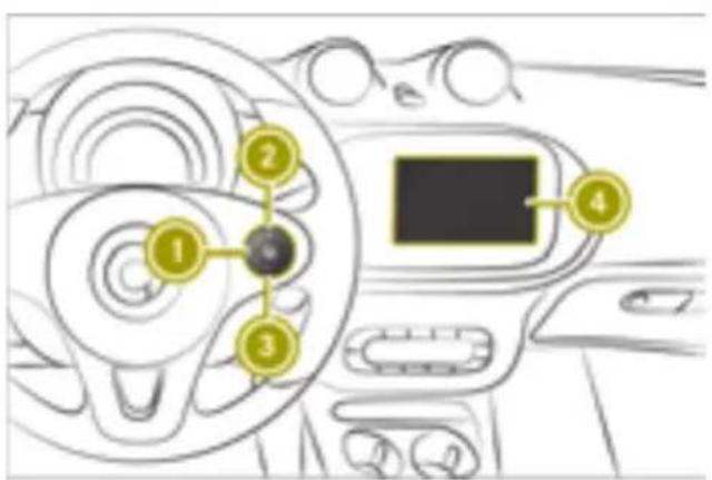
text_image
Diagram of a car dashboard with numbered components and a central touchscreen display① Switches voice control system on and off, accepts and ends a phone call
② + Increases the volume
③ — Reduces the volume
④ smart Media-System display
Voice control system
The following functions are possible using the voice control system of the smart MediaSystem:
- Enter a destination for navigation.
- Make a call.
- Start an application.
Controls on the smart Media-System
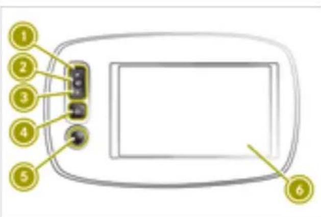
text_image
Diagram of a device panel with numbered labels pointing to key components① Previous station or track and fast rewind
② Mute
③ Next station or track and fast forward
④ Switches to the home screen
⑤ On/off button ⏻ and volume control
⑥ Touchscreen
Ports on the center console
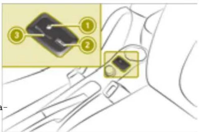
text_image
Diagram showing a device's internal components with numbered labels, likely illustrating a mechanical or electronic assembly.① Port for external audio equipment (AUX)
② USB port
③ SD card slot
Overview of home screen
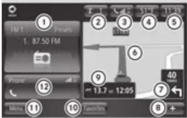
text_image
1 FM 1 1. 87.50 FM Phone Menu 11 10 Favorites 1 2 3 4 5 6 9 13.7 12:05 40 7 +① Radio station, media track
② Message memory
③ Status of the mobile phone and field strength of the mobile phone network
④ Outside temperature
⑤ Time
⑥ Map
⑦ Next navigation maneuver
⑧ Context menu
⑨ Distance to the destination and expected arrival time
⑩ Favorites menu
⑪ Main menu
⑫ Telephone menu, status of the mobile phone and field strength of the mobile phone network
i The home screen can be set to display energy flow.
Switching the smart Media-System on/off
Switching on automatically
▶ Start the engine.
Switching off automatically
▶ Switch off the ignition and open the door.
Switching on and off manually
▶ Press the ⏻ button.
To restart
▶ Press the ⏻ button. The smart Media-System shuts down and restarts.
i The restart can take several minutes. During the restart, the audio volume cannot be adjusted.
Scrolling through a menu or list on the touchscreen
▶ Touch the touchscreen with your finger.
▶ Swipe up, down, left or right.
The selection on the display will then me in the respective direction.
Selecting items on the touchscreen
▶ Tap on a menu, an option or an applicat with one finger.
The menu, the option or the application launched.
Controlling media playback on the touchscreen
▶ Swipe to the left.
The next media item is played or displayed, e.g. the next track or station.
▶ Swipe to the right.
Playback is restarted or the previous media item is played or displayed, e.g. the previous track.
Media playback can be controlled in the following playback modes:
the Radio mode
• Music and audio playback
- Image playback
- Video playback
Calling up menus
▶ Select Menu on the home screen. Select one of the following submenus:
• Multimedia
Radio and media playback
- Navigation
Navigation system
• Telephone
Mobile phone functions
• Vehicle
eco score, energy flow and consumption details
• Services
Apps and TomTom services
- System
General systems settings
Confirming settings
▶ Select Done.
Settings are accepted.
Switching off the display
▶ Select home page > + > Switchhoff display.
Adjusting the system settings
Adjusting the display
Setting the daytime brightness
▶ Select System > Display.
▶ Move the Daytime brightness control to the left or right.
Setting the nighttime brightness
▶ Select System > Display.
▶ Move the NNghttimebbrightness control to the left or right.
Activating automatic switching between daytime and nighttime brightness
▶ Select System > Display > Automatic day/night mode.
Displaying night mode constantly
▶ Select Force might mode.
Setting the system language
▶ Select System >Language.
A list of available languages is displayed.
▶ Select the desired language.
i The language of the spoken navigation commands can be selected independently of the system language.
Changing the on-screen keyboard
▶ Select System × Keyboards.
▶ Select one of the following keyboard layouts:
- Latin
- Greek
• Cyrillic
For the Latin keyboard layout, it is possible to choose between the ABC, QWERTY, AAERRTY and QWERTZ layouts.
Selecting the home screen display
▶ Select System ➤ Homepage.
A selection of home screen displays appears.
▶ Select the desired display.
Restoring the factory settings
▶ Select System >Factory settings.
▶ Confirm with Yes.
All settings changed in the system will return to the default values. All destinations, routes and Favorites will be deleted.
Setting the time manually
▶ Select System > Clock > Set time.
▶ Change the minutes and hours of the time shown.
Activating automatic time adjustment
▶ Select System > Clock > Set time > Automatic time adjustment.
Setting the time format
▶ Select System > Clock > Time format.
▶ Choose one of the following time formats:
• 18:00
• 6:00 PM
6:00
Displaying status and information
▶ Select System > Status & Information.
▶ Select one of the following information options:
- Version information
Software and hardware of the Media-System
• GPS status
Current GPS signal strength
• Network status
Signal strength of the data connection - Licenses
For free and open-source software used - Copyright
For texts in the TomTom software used
Adjusting surround sound (balance)
▶ Select Multimedia > Settings > Sound > Balance > Manual.
▶ Move the control to the desired position.
▶ Confirm with Done.
Adjusting the bass and treble
▶ Select Multimedia > Settings > Sound > Bass/Treble > Manual.
▶ Use the control to adjust the bass and treble separately.
Adjusting the audio settings
Setting the volume
▶ Select System > Sound > Volumes.
▶ Select one of the following volume settings:
• Main volume
For the whole system
- Hands-free
For the hands-free system
- Ringtone
The volume of the ringtone
- Navigation
Volume for the whole navigation system
• Computer voice
Volume of the computer-generated voice
- App events
Volume of events triggered by apps
▶ Set the desired volume.
Adjusting the volume to the vehicle speed (vehicles without JBL sound system)
The speed-dependent volume adjustment function adapts the volume to the current vehicle speed.
▶ Select System > Sound > Speed dependency.
▶ Move the Speed dependency control to the left or right.
The higher the value, the more the volume increases with the speed of the vehicle.
Volume adjustment is not set using the control but automatically.
Setting a neutral sound for the bass and treble
▶ Select Multimedia > Settings > Sound > Bass/Treble > Neutmall. Audio is played without increasing the bass or treble.
Activating and deactivating arkamys® bass boost (vehicles without JBL sound system)
The arkamys® bass boost setting emphasizes the bass during playback.
▶ Select Multimedia > Settings > arkamys bass boost.
Manual activation of arkamysbass boost on models with a JBL sound system is not possible. Activation functions automatically.
Setting the volume for warning tones
▶ Select System > Sound > Warnings.
▶ Move the control to the left or right.
Enabling warning tones when the display is switched off
▶ Select System > Sound > Warnings > Sound warning tones when display turned off.
Creating and deleting favorites
Creating Favorites
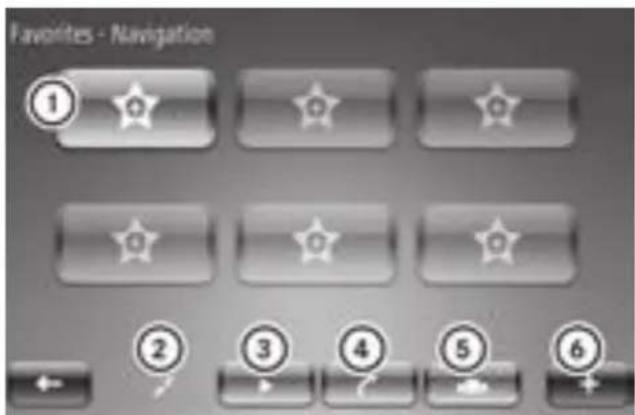
text_image
Favorites - Navigation ① ★ ② ★ ③ ★ ④ ★ ⑤ ★ ⑥① Preset
② Navigation
③ Radio
④ Telephone
⑤ Services
⑥ Context menu
Frequently used settings such as phone contacts and radio stations can be stored as Favorites. Six Favorites can be stored for each of the following categories:
- Navigation
- Radio
- Telephone
- Services
▶ Select Favorites on the home screen.
▶ Select category.
▶ Select the next empty memory position. A list of possible Favorites appears.
▶ Select Favorites.
Deleting Favorites
▶ Select Favorites on the home screen.
▶ Select + > Remove a Favorite.
▶ Perform one of the following steps:
- Select the favorite to be removed and press Delete to confirm.
- To delete all favorites, select Remove all Favorites.
Listening to the radio
Switching on the radio
▶ Select Multimedia > Radio.
Display modes
Useful information
In radio mode there are three different display modes, in which various settings can be made:
- "List" display mode
• Frequency display mode
• "Presets" display mode
"List" display mode
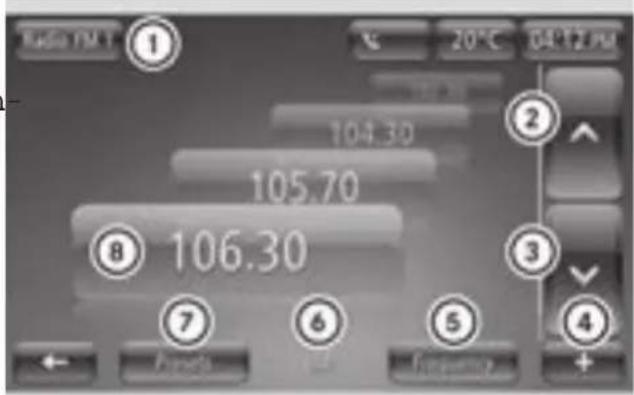
text_image
Radio TM 1 ① 20°C 04:12 PM 104.30 ② 105.70 ⑧ 106.30 ③ ⑦ ⑥ ⑤ +① Selects radio mode and memory level
② Selects previous station
③ Selects next station
④ Context menu
⑤ Selects "frequency" display mode
⑥ "List" display mode
⑦ Selects "presets" display mode
⑧ Station currently playing
Frequency display mode
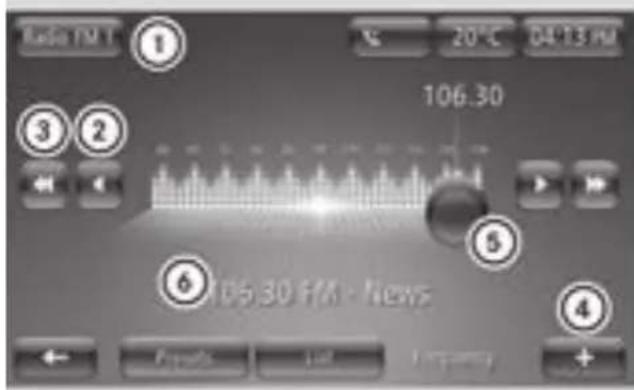
text_image
Radio FM 1 20 °C 04:13 PM 106.30 3 2 5 6 106.30 FM - News 4 Open Add +① Selects the waveband and preset group (FM)
② Increases or decreases the frequency in small increments
③ Station search, forward or back
④ Context menu
⑤ Adjusts the frequency manually
⑥ Station currently playing
"Presets" display mode
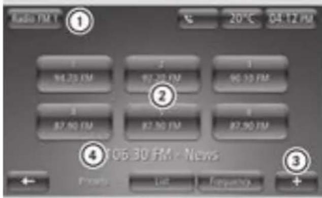
text_image
Radio FM ① 20℃ 04:12 PM 86.25 PM 87.30 PM 86.35 PM 87.90 PM 87.90 PM ② 1 1 1 ④ 06:30 PM - News ← Fronts List Follow up +① Selects the waveband and preset group (FM/DAB)
② Stored station
③ Context menu
④ Station currently playing
Selecting a station
"List" display mode
▶ Swipe up or down in the station list
▶ Tap on the desired station.
- Swipe up or down in the station list - Tap on the desired station.
Frequency display mode
▶ Slide control on the waveband left or right
Starting a station search
▶ Select ◀◀◀ or ▶▶◀ in the "frequency" di play mode
Storing a station
▶ Set the station.
▶ Select + > Save as preset.
Up to six stations can be stored for each waveband.
Displaying radio text
Radio text contains information such as current track or latest news.
▶ Select + > Show radio text.
Other radio settings
Receiving traffic reports (i-Traffic)
▶ Select Multimedia > Settings > Radio > i-Traffic (Traffic program).
Displaying the program type (e.g. classical music)
▶ Select Multimedia > Settings > Radio > PTY (Program type).
Updating the station list
▶ Select Multimedia > Settings > Radio > Update radio list.
Calling up electric drive displays
Calling up the energy flow display message
▶ Select Menu > Vehicle > electric drive > Energy flow.
The Energy flow display shows the flow of energy in the vehicle.
The energy flow is displayed in color, this indicates the following:
- Green coloring: energy is being recuperated
- Orange coloring: drive is consuming energy
- Yellow color and example illustration of the consumer: auxiliary consumers are using energy
- Gray color: no energy is being recuperated or consumed
Calling up consumption details
▶ Select Menu > Vehicle > electric drive > Consumption details.
The Consumption details display shows the energy consumption of the drive and electrical consumers as well as the energy recuperated during the previous 15 minutes. The display also shows the overall consumption of the drive and auxiliary consumers as well as the total recuperated energy of the current trip.
The Consumption details display is reset each time the engine is switched on.
Using a mobile phone
Connecting a mobile phone
Please note

WARNING
The electromagnetic radiation from two-way radios can interfere with the vehicle electronics if two-way radios are manipulated or retrofitted incorrectly. This could jeopardize the operating safety of the vehicle. There is a risk of an accident.
You should have all work on electrical and electronic components carried out at a qualified specialist workshop.

WARNING
If you incorrectly operate two-way radios in the vehicle, the electromagnetic radiation may interfere with the vehicle electronics, for example if:
- the two-way radio is not connected to an exterior antenna
- the exterior antenna is not correctly mounted or is not low-reflection
This could jeopardize the operating safety of the vehicle. There is a risk of an accident.
Have the low-reflection exterior antenna installed at a qualified specialist workshop. Always connect two-way radios to the low-reflection exterior antenna when operating in the vehicle.
Bluetooth ^® must be enabled both on the mobile phone and on the smart Media-System.
Enabling and disabling Bluetooth®
The mobile phone must be compatible with the smart Media-System.
For an overview of compatible mobile phones, visit: https://www.smart.com/connect.
▶ Select Settings > Turn Bluetooth on.
The setting is marked. Bluetooth this enabled or disabled on the smart Media-System.
Authorizing a mobile phone
Authorizing a mobile phone for the first time
Bluetooth ^® must be enabled on the smart Media-System.
▶ Select the PPhone menu.
▶ Confirm the display message with Yes.
▶ Enter the security code on the mobile phone or accept access confirmation (see the manufacturer's Operator's Manual). The message E-mailing BBluebot this shown.
Authorizing another mobile phone
Bluetooth ^® must be enabled on the smart Media-System.
▶ Select Settings > Manage phones.
The list of visible mobile phones is displayed.
▶ Select a mobile phone from the list.
▶ Enter the security code on the mobile phone or accept access confirmation (see the manufacturer's Operator's Manual). The Bluetooth® connection is established. The Bluetooth® connection will be established automatically in future.
Downloading telephone data automatically
▶ Select Settings > Automatically download phone data.
If necessary, accept the access confirmation on the mobile phone.
During connection, up to 1000 contacts are automatically transferred to the smart Media-System.
Connecting another authorized mobile phone
▶ Select Settings > Manage phones.
▶ Select a mobile phone.
The current Bluetooth ^® connection is terminated. The desired mobile phone is connected to the smart Media-System instead,
Removing a mobile phone from the list
▶ Select Settings > Manage phones.
▶ Select + > Deleted devices(s).
▶ Select a mobile phone.
▶ Select Delete.
Terminating a Bluetooth® connection
▶ Select Settings > Manage phones.
▶ Select + > Disconnect all devices.
▶ Select a mobile phone.
If the mobile phone leaves the Bluetooth®th receiver range, the connection is automatically terminated.
Using the telephone
Useful information
The following conditions must be fulfilled in order to make a 999 or 112 emergency call:
- A valid and operational SIM card is inserted in the mobile phone.
• A mobile phone network is available.
Calling a contact from the phone book
▶ Select Phonebook.
▶ Select the contact.
▶ Select the contact's telephone number.
If the phone book contains multiple contact they can be called up using a search
Dialing a number
▶ Select Dial a Number.
▶ Enter a number on the keypad.
▶ Select Call.
Calling a contact from the call log
▶ Select Call Logs.
▶ Select an entry from the list.
The call log can be sorted according to calls made, calls received and missed calls using the corresponding receiver icon.
^d Accepting and rejecting an incoming call
If a call is incoming, the following information will appear on the display:
- Name of caller, if already in the phone book.
• Number of caller, if name of caller not already in the phone book - Private number, if the caller has Hide caller ID switched on
▶ To accept the call, select Accept.
▶ To reject the call, select Reject.
The call will be forwarded to voice mail.
Holding and continuing a call
▶ Select + > Place on hold.
▶ To continue the call, select to continue.
Transferring a call to the mobile phone
▶ Select + >Handset.
Ending a call
▶ Select End call.
Using the Smartphone Screen application
Selecting settings for the Smartphone Screen
Selecting the preferred Smartphone Screen application
If mobile phones support Android Auto ^™ as well as MirrorLink ^™ , the preferred application can be selected when a mobile phone connected.
▶ Select System > Smartphone Screen > Smartphone Screen application preference.
▶ Select Android Auto ^TM or MirrorLink ^TM .
Selecting settings to start Android Auto ^TM and MirrorLink ^TM
▶ Select System > Smartphone Screen > Android Auto Settings.
or
▶ Select System > Smartphone Screen > MirrorLink™ Settings.
▶ Select one of the following settings:
- Ask me at each launch
If the Smartphone has been connected with the smart Media-System, you will be asked whether the preferred Smartphone Screen application should be started.
- Yes
If the Smartphone has been connected with the smart Media-System, the preferred Smartphone Screen application will be started automatically.
• No
If the Smartphone has been connected with the smart Media-System, a Smartphone Screen application will not be started.
Using MirrorLink™
Useful information
MirrorLink ^™ is standard for the connection between the smart Media-System and a mobile phone. With MirrorLink ^™ , the content of the display on your mobile phone can be displayed in the smart Media-System.
MirrorLink™ is available for mobile phones with the "Android" operating system.
Further information: http://www.smart.com/connect.
To use MirrorLink ^™ , observe the following requirements:
- the mobile phone must support Mirror-Link™ version 1.1 and above
• the mobile phone is switched on - a MirrorLink™ certified app must be installed on the phone
- the GPS connection must be activated on the mobile phone
- the time is set on the smart Media-System
Setting up a connection
▶ Activate MirrorLink™ on your mobile phone (see the manufacturer's operating instructions).
▶ Connect a mobile phone with a connecting cable to the USB socket in the center console.
▶ Select Yes.
Apps which have been certified for MirrorLink™ will be shown in the smart Media-System display.
Calling up MirrorLink™ Apps
▶ Tap on the home page of the smart Media-System 📋.
MirrorLink™ starts in the smart Media-System display.
▶ Select the desired app.
The display switches to full screen mode.
▶ To leave full screen display: press and hold the button on the smart Media-System until the lower bar is shown.
▶ To exit the display: select ←.
MirrorLink™ audio playback
The following system information is trans- mitted:
If your mobile phone supports this function, ^mitted :
you can control audio playback via the but-• multimedia system software version
tons on the smart Media-System.
- system ID (anonymous)
▶ To select the previous track: press the button.
This data is transmitted in order to optimize communication between the vehicle and
▶ To rewind: press and hold the ▲ b
buttonmobile phone.
▶ To select the next track: press the ▼ button.
▶ To fast forward: press and hold the ▼ button.
▶ To mute: press the 📁 button.
Disconnecting the MirrorLink™ connection
▶ Select + > Disconnect.
Using Android Auto™
Useful information
Android Auto™ is an application for the connection between the smart Media-System and a mobile phone. Certain mobile phone functions and apps can be controlled via the smart Media-System with Android Auto™.
Functions such as telephony, navigation and the audio playback of Android Auto™ are displayed on the home page of the smart Media System.
Android Auto ^™ is available for mobile telephones with the Android operating system. Further information: http://www.smart.com/connect.
A random vehicle code is generated for this purpose and in order to assign multiple vehicles to the mobile phone.
The following driving status data is trans-
mitted:
- gear position engaged
• instrument cluster day/night mode
This data is transmitted in order to adapt content displayed to the driving situation.
GPS data such as coordinates, speed and compass direction is transmitted. This data is transmitted only when navigation is active in order to improve navigation (e.g.
^1 when driving through a tunnel).
Setting up a connection
Active Android Auto™ on the mobile phone (see manufacturer's operating instructions).
^15 Connect a mobile phone with a connecting cable to the USB socket in the center console.
▶ Select Yes.
Android Auto ^™ starts in the smart Media-System display.
In order to use Android Auto™, the following conditions must be met:
- the mobile phone supports Android Auto™ starting from Android™ 5.0
• the mobile phone is switched on - the mobile phone has an Internet connection
- the Android Auto™ App is installed on the mobile phone
Transmitted vehicle data when using Android Auto
When using Android Auto, specific vehicle data is transmitted to the mobile phone. This makes it possible to use selected mobile phone services efficiently. The mobile phone does not have active access to vehicle data.
Calling up Android Auto™
▶ Tap on the home page of the smart Media-System ▲.
Android Auto™ starts in the smart Media-System display.
Activating Android Auto™ voice-operated control
When Android Auto ^™ is activated, the system can be operated with voice control.
▶ Press and hold the button on the multifunction steering wheel for approximately three seconds.
A tone sounds.
Disconnecting Android Auto™
▶ Disconnect the USB connection between mobile phone and multimedia system.
Using voice control for the mobile phone
Useful information
The voice control of the connected mobile phone can be used (see manufacturer's operating instructions). Not all voice control services are supported by the smart Media-System.
The requirement for voice control of the mobile phone is that Android Auto ^TM or MirrorLink ^TM are not active.
Activating voice control for the mobile phone
- Connect the mobile phone with the smart Media-System via Bluetooth
▶ Press and hold the button on the steering wheel. The symbol appears in the display. Voice control for the mobile phone is active.
Further settings
Setting the volume
▶ Select Settings >Volumes.
▶ Set the volume of the hands-free system and the ringtone.
Activating voice mail
▶ Select Voiceman1.
▶ Enter the voice mail number on the keypa
▶ Select Done.
Voicemail is activated and the voicemail number is dialed.
Configuring voicemail
▶ Select Settings > Voicemail configuration.
Updating the phone book
A Bluetooth ^® connection must be present.
▶ Select Phonebook > + > Update phone data.
Updating the call log
▶ Select Call logs > + > Update phone data.
Adding a contact to Favorites
▶ Select Phone > Phonebook.
▶ Select a contact from the list.
▶ Select + > Add to Favorites.
▶ Dial a phone number.
Connecting and operating external data carriers
Useful information
The following external data carriers can be connected:
- USB memory stick (USB 2.0 or 3.0 with max. 64 GB) or iPod™
• SD or SDHC card (max. 64 GB) - External audio equipment (AUX jack)
-
Bluetooth ^ devices such as mobile phones The following formats are supported:
-
MP3 files
- WMA files
- ACC formats (.AAC, .M4A, .M4B, .M4P, .M4V, .M4R, .MP4 and .3GP)
- OGG Vorbis (.OGG, .OGA)
• PCM 16 bit (.WAV, .PCM)
A data carrier may contain no more than eight directory levels.
The smart Media-System only recognizes the first partition of a data carrier. The partition must be formatted as FAT or FAT32.
Connecting external data carriers
Connecting a USB memory stick
▶ Insert a USB memory stick in the port on the center console. Playback starts automatically.
Connecting an SD card
▶ Insert an SD card into the SD card slot in the center console. Playback starts automatically.
Connecting a Bluetooth ^® device
▶ Authorize and connect a Bluetooth device, such as a Bluetooth-capable mobile phone.
Operating external data carriers
Selecting connected external data carriers
- Select Menu > Multimedia > Media. - Select connected medium.
Controlling playback from a USB memory stick or SD card

text_image
USB ①② 50 P 13.28 ③ ④⑤ Betney Spears (You Drive Me) Crazy (Th... greatest hits: My Parnegative 00:34 ⑨ 03:18 ⑧⑦ New Make Off Last Made Behind +① Selects the previous track
② Selects the next track
③ Stops and continues playback
④ Switches track repeat on
⑤ Switches random playback on
⑥ Calls up the context menu
⑦ Displays the playlist
⑧ Selects a new track based on categories, e.g. album, genre, folder
⑨ Resumes playback at any point in the track
Controlling playback from a Bluetooth® device
text_image
Phone Peter Park Hungry Eyes (WIR Club Mix) Cukha Candela Hungry Eyes - Single ① ② ③ ④ ⑤ ⑥① Selects a new track
② Selects the previous track
③ Stops playback
④ Selects the next track
⑤ Displays the playlist
⑥ Calls up the context menu
Selecting a different device
▶ Select + >Changes source.
Connecting another authorized Bluetooth® device
▶ + > Select Find new device.
Enabling and disabling random playback
▶ To enable: select + Enable leamrandom playback.
▶ To disable: select + Disatslab Ie randomom playback.
Displaying details of tracks on a USB memory stick or SD card
▶ Select + >TranackDETAILS.
Selecting a track from current playlist
▶ Select New selection folders.
The current playlist is displayed.
▶ Select Find.
A keyboard is shown.
▶ Enter the name or part of the name of the Select New selection. track you are looking for.
▶ Swipe left or right.
Select New selection.
Selecting a track from categories
▶ Select New selection.
▶ Select category for playback.
Switching album cover display on and off
The album cover must be saved in the audio file.
▶ Select Multimedia > Settings > Media > Display album cover.
Viewing images
Useful information
Images that have been saved to an SD card or Tap the touchscreen. USB memory stick can be viewed in the smart Media-System. Switching from full sc
The following file formats can be displayed:mal view
▶Tap the touchscreen.
• .JPG
• .GIF
• .PNG
• .BMP
Image playback
Starting image playback
▶ Insert SD card or USB memory stick into corresponding port.
▶ Select Multimedia > Pictures.
▶ Select media source USB or SD.
▶ Select folder.
▶ Select image.
Switching between images
Specifying a new selection of images
Setting image playback
Switching from normal to thumbnail view
▶ Select Thumbnails.
Switching from thumbnail to normal view
Select an image.
Displaying in full screen mode
▶ Select + > Full is screen.
Activating the controls in full screen mode
Switching from full screen mode to normal view
▶ Select + >No nonanla lv review.
Enlarging the image
▶ Select + >Zoommin.
Showing images as a slide show
▶ Select + >Slidesshow.
the
Setting the display duration
▶ Select + > Image settings > Slide show delay.
▶ Set the desired time using the controls.
Setting default view for image playback
▶ Select + > Image settings > Default view.
▶ Select Normal view or Full screen.
Video playback
Video playback
Starting video playback
▶ Insert SD card or connect USB stick.
▶ Select Multimedia > Video.
▶ Select USB or SD.
▶ Select folder or video.
All videos in a folder are played one after the other.
The size of the video file may have an impact on the performance of the system. Therefore, only playback videos with a length of up to 5 minutes.
Selecting the next or previous video
▶ Select ▶▶| or ◀◀.
Stops and continues playback
▶ Select □.
Playing a new video
▶ Select New selection.
▶ Select a new video
Setting the video view
Playing videos in full screen mode
▶ Select Full screen.
Setting the default view for video play-back
▶ Select + > Video settings.
▶ Select Normal view or Full screen.
Using the navigation system
Starting the navigation system
Please note
WARNING
If you operate information systems and communication equipment integrated in the vehicle when driving, you may be distracted from the traffic situation. You could also lose control of the vehicle. The is a risk of an accident.
Only operate this equipment when the traffic situation permits. If you are not sure that this is possible, park the vehicle paying attention to traffic conditions and operate the equipment when the vehicle is stationary.
The navigation system does not provide information on stop signs, right of way sign traffic regulations or road safety regulations.
Traffic regulations always take priority over the navigation system's driving recommendations.
Observe the legal stipulations and traffic regulations of the country you are driving in when in navigation mode.
Starting the navigation system
▶ Select Menu >Navigation.
The following functions can be carried out:
- Searching for a destination
- Planning a route
- Displaying a map
- Calling up TomTom services
- Changing navigation settings
Reading map data
WARNING
SD cards are small parts. They can be swallowed and cause choking. This poses an increased risk of injury or even fatal injury.
Keep the SD card out of the reach of children. If a SD card is swallowed, seek medical attention immediately.
▶ Select the destination from the list.
▶ Select the street.
▶ Select the house number.
▶ Confirm with Done.
! To prevent damage to data, only use the SD card provided for the data in the Medi System or for updating map and systems files.
^1a Searching for a parking lot near the destination address
▶ Insert an SD card into the SD card slot in This function can be called up when entering the center console. the destination.
▶ Switch on the device.
The map data is read by the navigation system.
This function can be called up when entering the destination.
▶ Select + > Nearby parking lot.
A list of parking lots near the current destination appears.
Removing an SD card
▶ Select Menu > System > Remove SD-card.
▶ Confirm the display message with Yes.
▶ Press the SD memory card.
▶ Remove the SD card from the slot.
Displaying information about the destination address
This function can be called up when entering the destination.
▶ Select + >Showinfo.
Updating map data
Regular updates are supplied for the map data. The first update can be downloaded for free in the web portal within 90 days of vehicle activation. This requires registration at http://tomtom.com/forsmart. Further information is available from any smart center.
▶ Remove SD card from the vehicle and insert into a computer.
▶ Install update software on the computer.
▶ Run the map update assistant.
Entering a destination using the map
A location on the map can be selected as the destination.
Select Navigation > Drive to... > Point on map.
▶ Align map view with the destination.
▶ Tap the destination point on the display.
ert The symbol selected is highlighted in blue.
▶ Tap on the symbol to confirm.
Entering a destination using the voice control system
▶ Press the button on the multifunction steering wheel.
A tone sounds.
▶ Say the command "Enter address".
▶ When prompted by the voice control system, say the destination address, including street name, house number and city.
▶ Say the voice command "Yes" or, if several possible destinations are displayed, say the number.
As well as updates, the latest software f the Media-System can be downloaded and Premium Voices by TomTom can be purchased.
Entering and managing destinations
Entering a destination by address
▶ When using the navigation system for the first time, enter country.
▶ Select Navigation >Drive to... >Address.
▶ If desired, change the country using the flag symbol.
▶ Enter city or ZIP code.
Selecting a destination from the list of last destinations
▶ Select Navigation >Drive to... >Recent destinations.
▶ Select destination.
Entering a destination using geo-coordinates
▶ Select Navigation > Drive to... > Latitude Longitude.
▶ Enter the longitude and latitude
Setting home location
▶ Select Navigation > Settings > Set home address.
▶ Enter a home address
Setting home as a destination
▶ Select Navigation > Drive to... > Home.
Selecting a saved location as destination
At least one destination must be stored for this function.
▶ Select Navigation > Drive to... > Saved locations.
▶ Select destination.
Managing saved locations
▶ Select Navigation > Settings > Manage saved locations.
Entering a charging station as a destination
▶ Select Navigation > Drive to... > Charging stations.
The following list of locations appears in which a charging station can be searched for:
- POI near you
- POI along route
-
POI near destination
-
POI near Home
- POI in city
▶ Select the location for the charging station search.
A list of the corresponding charging stations appears. There is an automatic check whether a charging point is free on these charging stations. The check may take several minutes. When the check is finished, a message appears. If a charging station has a charging point which is not being used, it will be marked green. If no charging point is free, or no information available, the charging station is marked gray. Charging stations from the map data which cannot be checked, are not marked. A maximum of 24 charging stations can be checked.
Five minutes after the check, the marking automatically changes from green to gray
▶ Select a charging station.
Entering a point of interest
POIs such as museums, restaurants or car parks near a location are displayed on the map.
▶ Select Navigation > Drive to... > Point of interest.
The following list of surrounding areas appears. A POI can be searched for in these areas:
- POI near you
- POI along route
- POI near destination
- POI near Home
- POI in city
▶ Select surrounding area for the search for a POI.
The following list of categories for POIs appears:
- List of categories for POIs: e.g. charging station or restaurant
- POI name search
• POI search within a category
▶ Select a category for the search.
▶ Select a POI.
If the charging station category is selected, only charging stations from the map data are searched. Charging stations that
can be checked for charging point availability are not taken into account.
Managing POIs
Adding a POI category
▶ Select Navigation > Settings > Manage POIs > Add POI category.
▶ Enter the name and symbol for the new POI category.
Deleting a POI category
▶ Select Navigation > Settings > Manage POIs > Delete POI category.
▶ Select the POI category to be deleted.
Adding POIs
▶ Select Navigation > Settings > Manage POIs > AAddPBDI.
If no POI categories have been defined yet a prompt appears to enter a POI category.
▶ Select the category for the POI.
▶ Enter your POI.
Deleting POIs
▶ Select Navigation > Settings > Manage POIs > DeletePOI.
▶ Select POI category.
▶ Select the POI to be deleted.
Editing POIs
▶ Select Navigation > Settings > Manage POIs > EEditPDOI.
▶ Select POI category.
▶ Customize the POI properties.
Setting alerts for a nearby POI
▶ Select Navigation > Settings > Manage POIs > Warning when near POI.
▶ Select POI category.
▶ Set the distance at which the message should appear.
▶ Set the type of alert issued.
Entering a destination via the TomTom LIVE service "TomTom Places"
POIs from the "TomTom Places" online database are available using the "TomTom Places" function.
▶ Select Navigation>Drive to...>TomTom Places.
A list of search criteria appears which can be used to search for a POI.
▶ Select the search criteria.
▶ Enter a search term.
If a large number of search results are available, 20 additional search results can be downloaded.
Changing the route
Useful information
Once the destination has been selected, the navigation system calculates the route to the destination. The following options are available for adjusting the route guidance:
- Calculate alternative routes.
- Adjust routes calculated by the navigation system.
- Plan routes in advance and travel via specific way points.
- Adjust settings for calculating routes.
Once the route is calculated, a route summary is shown. By default, the quickest route will be calculated for route planning, taking into account IQ Routes™. Traffic information is taken into account when calculating the route.
Depending on the remaining range, sections of the route receive the following colors:
- green: remaining range is expected to be sufficient for the route.
- orange: this route may or may not be able to be completed depending on the driving style and the influence of external factors.
- red: remaining range is not expected to be sufficient for the route.
The "route overview" function allows you to set whether the summary of a calculated route is automatically faded out from the display after ten seconds.
If the route is not confirmed with 0, the display automatically switches to map view after approximately ten seconds.
Displaying a planned route
Calculating the route
▶ Enter a destination.
▶ Select Done.
The route is displayed. If the remaining range is not expected to be sufficient to reach the destination, a prompt will appear asking whether a charging station should be added to the route.
Displaying the route details
▶ Select + >Routed details.
▶ Select one of the following functions:
- Display instructions
An overview of the route with direction appears.
• Display a map of the route
The route appears on a map.
• Display the destination
The destination for the route appears.
By pressing +, it is possible to search for a car park near the destination or add the location to the saved locations.
• Show traffic on route
Traffic disruptions along the route are shown.
- Summary
A summary of the route details appears
Route guidance via way point
The route can be adjusted by entering up to four way points.
▶ Select Navigation > Change route > Travel via.
If a way point has already been entered, list of the saved way points will be displayed.
▶ Select Add.
▶ Select a new way point from Address, Recent destinations, Sawed Locations, TomTom Places or POD.
The new way point is added.
Avoiding road blocks
The route can be changed if a section of road along the route is blocked or there is a traffic jam.
▶ Select Navigation > Change route > Avoid roadblock.
▶ Select the length of the route that needs to be avoided.
^add Avoiding specific roads
The route is calculated to avoid specific roads.
▶ Select Navigation > Change route > Avoid part of route.
A list of the roads on the route is displayed.
▶ Select the road you wish to avoid.
Saving a planned route
▶ Select + >SaveItinerary.
Changing the route
Canceling the route
▶ Select Navigation > Change route > Cancel route.
When a new destination is entered, route guidance can be resumed again.
Calculating an alternative route
▶ Select Navigation > Change route > Calculate alternative.
A new route is calculated and displayed that takes you on different roads.
▶ Select the alternative route or a previous one.
Taking traffic disruptions into account
The route is recalculated based on current traffic information
Traffic information is only available with HD Traffic.
▶ Select Navigation > Change route > Minimize delays.
An overview of the traffic disruptions along the route will be shown.
▶ Select the traffic disruption you wish to avoid.
Planning a route in advance
Adding a route
▶ Select Navigation >Routes.
▶ Select Add.
▶ Select the starting point of the route.
▶ Enter the route destination.
- Enter at least one way point for the route carpool lanes are lanes which can only be
- Enter the route name. used by vehicles with at least two occupants.
▶ Confirm with DBone.
€Carpool lanes are lanes which can only be used by vehicles with at least two occupants.
Starting navigation using a saved route
▶ Select Navigation >Routines.
▶ Select the desired route.
▶ Select + >Go.
Setting route planning
Selecting the route type
▶ Select Navigation > Settings > Route planning > Routetypes.
▶ Select one of the following settings:
- Ask for every route
• Always plan the fastest route
• Always plan eco routes
• Always avoid highways
• Always plan the shortest route
Selecting the setting for toll roads
▶ Select Navigation > Settings > Route planning > Toolroads.
▶ Select one of the following settings:
- Ask for toll roads on route
• Always avoid toll roads
- Do not avoid toll roads
Selecting the setting for ferry connections
▶ Select Navigation > Settings > Route planning > Feeryconnections.
▶ Select one of the following settings:
- Ask for ferries on my route
• Always avoid ferries
- Do not avoid ferries
Selecting the setting for unpaved roads
▶ Select Navigation > Settings > Route planning > Ubppacedroads.
▶ Select one of the following settings:
- Ask for unpaved roads on my route
- Always avoid unpaved roads
Selecting the setting for carpool lanes
▶ Select Navigation > Settings > Route planning > Carpool lane settings.
▶ Select one of the following settings:
- Ask for carpool lanes on my route
• Always avoid carpool lanes.
- Never avoid carpool lanes
Using information during route guidance
Useful information
Navigation messages provide guidance during the journey without distracting you from traffic conditions. The display also shows information about the route.
Switching navigation messages on and off
▶ Tap on the area of the next navigation maneuver during route guidance.
▶ Select Turn on voice guidance or Turn off voice guidance.
Information such as traffic reports and warnings will be played even if the navigation messages have been switched off.
During route guidance, traffic information can be shown for the route ahead. The following traffic information can be received:
- Traffic messages (TMC)
• HD Traffic (a TomTom Live service)
i HD Traffic Information takes precedence.
Live services are not available in all countries and regions. Further information: http://tomtom.com/services
Tracking navigation on the display
text_image
13th St 14th St 10th St 13rd St Shore 0.65 7:29 0.48 120 104.10 PM 1 ① ② ③ ④ ⑥ ⑦ Pavomia 104.10 PM 1 ⑤ +① Increases or reduces the map view
② Traffic information
③ Route information
Warning for remaining range to destination
④ Compass and symbol for two or three-dimensional map display
⑤ Context menu
⑥ Next navigation maneuver and symbol for volume adjustment
⑦ Information about current radio or media playback or information about active telephone calls
▶ Tap on an area or on a symbol in the map display:
- Map: to switch to the overview map
• ①: to zoom in and out of the map view
• ②: to show traffic reports on the route
• ③: to display the route details
• ④: to switch between two or three-dimensional map display
• ⑤: to open the context menu
• ⑥: to repeat the navigation instruction, change the volume of navigation announcements or switch off
• ⑦: to switch to the corresponding radio, multimedia or telephone menu
The navigation system zooms in on the map view as the vehicle approaches an intersec→Tap on the message on the touchscreen and tion. This makes it possible to follow turning swipe left or right. maneuvers more accurately.
Shortly before navigating a freeway intersection or exit, the display shows a three-dimensional representation of the lanes and the exit. Lane Keeping Assist is not available for all intersections in all countries.
Traffic information details
text_image
Diagram of a device panel with numbered components and labeled parts① Overall delay on route
② Traffic disruption (packed snow)
③ Traffic disruption (rain)
④ Traffic disruption (traffic jam)
⑤ Current position and distance to next traffic disruption
During route guidance, traffic information is shown for the route ahead. When there are number of traffic disruptions in quick succession, only the very next disruption on the route will be displayed.
Traffic information is only available with Traffic.
| Color Meaning | |
| Gray | Unknown or unexplained situation |
| Orange | Slow-moving traffic |
| Red | Traffic jam |
| Dark red | Standstill or road blocked |
Calling up more detailed information about the traffic problems
▶ Tap on the display for traffic information during route guidance.
Scrolling through the traffic reports
Tap on the message on the touchscreen and ng swipe left or right.
[Non-Text]
[Non-Text]
[Non-Text]
1
ole
[Non-Text]
Displaying the overview map
Useful information
With the "View map" function, the display shows a slidable, two-dimensional overview map. The map shows your current position, as well as a number of other elements, such as Favorites.
Displaying a map
▶ Select Navigation > Viewmap.
A map of the surrounding area will be shown.
▶ To search: select + > Search.
Controlling the map view
Moving the map
▶ Tap on the center of the touchscreen.
▶ Swipe in the desired direction. The map will then move in the respective direction.
Zooming in on the map
▶ Place two fingers slightly apart in the center of the touchscreen.
▶ Move your fingers away from each other.
Reducing the scale of the map
▶ Place two fingers, at a greater distance apart, on the screen. Do not place your fingers at the very top area or very bottom area of the display.
▶ Glide your fingers towards each other.
Displaying the reachability map
If no route is planned, a reachability map be displayed in order to roughly gauge the range with the current condition of charge.
▶ Select Navigation > Viewmap.
▶ Select + > View reachability map.
Showing and hiding additional information on the map
▶ Select Navigation > Viewmap.
▶ Select + > Change map information.
▶ Select one of the following information options:
- Traffic information
- Names
- Points of interest (POIs)
- Satellite images
- Coordinates
Using TomTom Services with the navigation system
Useful information
In the TomTomServices menu, traffic information and other TomTom-LIVE services can be called up and managed.
TomTom Live Services are available for a subscription fee. The following TomTom Services come pre-installed and, following activation, can be used free of charge for a period of three years:
- HD Traffic
- Radar cameras (not available in all countries)
- Weather
TomTom Places
More information on services
http://www.tomtom.com/services.
More information on availability in specific countries: http://smart.com/connect
TomTom Services can also be called up and managed in the Services menu. In the main menu, select Services > TomTom Services.
If you have subscribed to the "TomTom Traffic" service and this is available, the "Traffic info" menu will be called "TomTom Traffic".
can Activating TomTom Services
TomTom services must be activated in the smart Media-System before using them for the first time. If TomTom Services are not yet activated, a corresponding button will be displayed in the main menu and in the Services menu.
To activate TomTom services for the first time, observe the following requirements:
- an SD card with map data is inserted into the SD card slot
- a valid vehicle position is available on the map
- a mobile phone network is available
▶ Select Services > Activate My Services.
▶ Confirm the display message with yes. After a short while, TomTom Services are available.
▶ Select Services >TomTomServices. The TomTom Services installed on the device are displayed.
▶ Select the desired TomTom Service.
A display message appears. TomTom Services are activated.
Starting TomTom Services
▶ Select Navigation >Toronto Services.
Checking subscription status for Tom-Tom Services
▶ Select Navigation > TomTom Services > My Services. The services available on the device and their subscription status will be shown.
Displaying the traffic information along the route
▶ Tap on the area of traffic information during route guidance.
▶ Swipe left or right to switch between traffic information.
Adjusting the route according to traffic disruptions
▶ Select Navigation > TomTom Services > Traffic > Minimize delays.
A faster route that had been previously rejected or route which may not have been taken into account due to the never change my route setting for the traffic information is selected.
Displaying traffic disruptions on the overview map
Select + >Viewmanap during route guidance.
Traffic disruptions are displayed as symbols on the overview map. Large area traffic disruptions such as rain, fog or snow are displayed with several symbols.
▶ To view detailed information, tap on a tr fic disruption symbol.
The following symbols are used:
| Symbol Meaning | |
| Traffic jam | |
| Road blocked | |
| Traffic disruption | |
| Construction site | |
| One or several lanes blocked | |
| Accident | |
| Traffic disruption avoided using the traffic information | |
| Fog | |
| Wind | |
| Snow | |
| Black ice | |
| Rain | |
i Large area traffic disruptions such as rain, fog or snow are displayed on the overview map with several symbols.
Viewing traffic information for the route to work
▶ Select Navigation > TomTom Services > Traffic > Traffic info. for route to work.
▶ Select one of the following settings:
• Home to work
- Work to home
- Change the home to work route
Changing the settings for traffic information
▶ Select Navigation > TomTom Services > Traffic > Traffic info. settings.
▶ Select one of the following settings:
• Always change to this route
If a faster route has been calculated due to a traffic report, the navigation system automatically changes the route.
- Request confirmation for route
If a faster route has been calculated due to a traffic report, the navigation system will ask which route should be used.
- Never change my route
The navigation system will not change the route, even if a traffic announcement has been made.
- Read aloud traffic info when navigating
- Read aloud foreign street names
- Read aloud road numbers
- Read aloud street names
- Read aloud weather information
- Read aloud POI warnings
- Read aloud warnings
- Read aloud signposts
Changing the map
Select Navigation > Settings > Change map.
▶ Select the desired map.
Changing the map color
▶ Select Navigation > Settings > Change map colors.
Press ◀ or ▶ to select the desired display.
Setting the navigation system
Setting the voice
The voice which is used for navigation commands can be changed. It is possible to choose between computer-generated voices or voices recorded by professionals. For voices that have been recorded by professionals, only basic navigation commands will be spoken.
▶ Select System > Sound > Voice.
▶ Select voice for playback.
▶ To listen to the voice, select test.
Setting the voice output
The read-aloud function is only available a computer-generated voice.
▶ Select System > Sound > Voice output settings.
▶ Select one of the following settings:
- Read early warning instructions (for example, ahead, turn left)
- Read aloud highway lane instructions
Changing the settings for electric drive
▶ Select Navigation > Settings > electric drive settings.
The following functions can be called up:
- activating or deactivating the battery warning
When the condition of charge of the high-voltage battery has reached 20% and the battery warning is activated, a display message appears. - hiding or displaying charging stations on the map
• managing charging stations - selecting a charging cable
The specified charging type and charging cable type settings are used for navigation in inorder to limit the selection of the available charging stations. During navigation, the following options can be selected via the + context menu:
- search for type of charging
• search for electricity provider
• display all charging stations
A display message appears if the specified settings and a selected charging station are incompatible.
Setting safety warnings
▶ Select System > Safetywarmings.
▶ To select the desired settings:
• Suggest driving breaks
- Warn when driving near schools
- Warn when driving faster than allowed
- Warn when driving faster than a set speed
▶ Select Resume.
▶ Select a warning tone for the respective safety warning.
For the "Warn when driving faster than a set speed" function, the speed above which the warning tone should sound must be entered.
Setting the units of measurement for distance
All units of measurement for distance in the navigation system can be changed. The units of measurement for distance in the on-board computer are not changed.
▶ Select System > Set units > Distance units.
▶ Select one of the following settings:
- Kilometers
• Miles
Setting the units for GPS coordinates
▶ Select System > Set units > GPS coordinate display.
▶ Select one of the following settings:
- Degrees (d°)
- Degrees, Minutes (d° m.m')
- Degrees, Minuites, Seconds (da°mm)\ 'ss\ '')
Managing apps
Useful information
If available, apps may be installed and manMedia-System. This will require registration aged on the smart Media-System. Apps and at http://tomtom.com/forsmart.
the use of TomTom services can be called up Remove SD card from the vehicle and insert and managed in the service menu. into a computer.
The smart Media-System uses a mobile phone connection for data connection. Please take note of the following information when using data services:
- The mobile connectivity and built-in SIM card for this vehicle can only be used for certain data services. These are offered by certain third parties, as well as Daimler A. Usage occurs via the smart Media-System in the vehicle. The use of data services requires the conclusion of separate agreements between the vehicle user and the respective provider. Voice service usage is not permitted. As such, the SIM card must be permanently installed as factory equipment.
• The mobile communications connectivity and the SIM card may only be used responsibly in accordance with the applicable laws and other legal requirements of the corresponding countries. Insofar as this is within the power of the vehicle user. • Upgrading, reproduction, reverse assembly and disassembly of the SIM card are not permitted. Statutory authority remains unaffected.
Failure to follow the above instructions can in some cases lead to temporary or permanent deactivation of the mobile connection and the SIM card. This depends on the severity of the non-compliance. The measures described here, in particular, protect Daimler AG and its contractual partners from negative legal consequences arising from non-compliance. The availability of mobile connectivity in individual countries depends on the existence of corresponding mobile service agreements with local mobile network providers. Availability can therefore change from time to time. The maximum period of validity for the mobile connectivity is 15 years from the time of installation in the vehicle.
Installing apps
If available, apps may be used on the Smart Media-System. This will require registration at http://tomtom.com/forsmart.
Remove SD card from the vehicle and insert into a computer.
Further information: http://tomtom.com/ forsmart.
Displaying and calling up apps
Displaying apps
▶ Select Services > Settings > Applications manager.
The apps installed on the SD card are shown in the smart Media-System.
Calling up apps
▶ Select Services.
▶ Select the desired app.
Calling up the connectivity manager
The connectivity manager allows you to manage the devices connected to the smart Media-System.
▶ Select Services > Settings > Connectivity manager.
Managing data sharing
Enabling or disabling data sharing
If data sharing has not been enabled beforehand, a corresponding message is shown when the smart Media-System is started up. Data sharing can be enabled or disabled at any time.
▶ Select Services > Settings > Data sharing.
▶ Select one of the following settings:
• Yes
Enable data sharing
• No
Disable data sharing.
Displaying additional information
▶ Select Services > Settings > Data sharing > About.
Displaying text in another language
▶ Select Services > Settings > Data sharing > Language.
Stowing small objects
Please note

WARNING
If you stow objects in the vehicle interior if an unsuitable way, they could slip or be thrown around and thus hit vehicle occupants. Additionally, the cup holders, open stowage spaces and mobile phone brackets cannot restrain the objects placed in them in the event of an accident. There is a risk of injury, especially in the event of braking or sudden changes in direction.
- Always stow objects so they cannot be thrown around in these or similar situations.
- Always ensure that objects do not protrude from the stowage compartments or stowage nets.
- All closable stowage compartments should be closed before beginning your journey.
- Always stow and secure heavy, hard, pointed, sharp-edged, fragile objects or objects which are too large behind the last bench seat or under the passenger seats.

WARNING
The cup holder cannot hold a container secure whilst traveling. If you use a cup holder whilst traveling, the container may be flung around and liquid may be spilled. The vehicle occupants may come into contact with the liquid and if it is hot, they may be scalded. You may be distracted from the traffic conditions and you could lose control of the vehicle. There is a risk of an accident and injury.
Only use the cup holder when the vehicle is stationary. Only use the cup holder for containers of the right size. Always close the container, particularly if the liquid is hot.
! Only use the cup holders for containers of the right size and which have lids. The drinks could otherwise spill.
iUsing the compartments
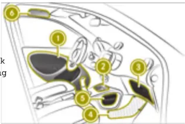
text_image
Diagram of a car interior with numbered parts, likely indicating components or sections in a vehicle's dashboard.▶ To stow objects, use the following compartments:
• ① Stowage compartments in the doors
• ② Cup holder in the front center cons
• ③ Glove box
- ④ Stowage net in the front-passenger footwell
• ⑤ Sliding drawer in the center consol
- ⑥ smart fortwo coupe electric drive: eyeglasses compartment above the driver's seat and above the front-passenger seat
- Cup holder in the rear center console with a recess for storing a mobile phone
- smart fortwo coupe electric drive: stow-age compartment in the lower tailgate
- Stowage net with two net pockets on the back of the trunk partition
Locking/unlocking the glove box
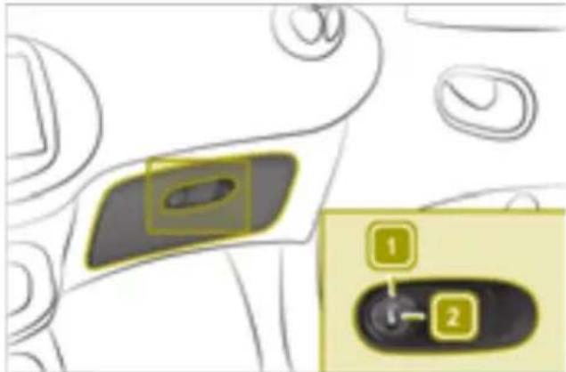
text_image
Diagram showing a device control panel with labeled buttons 1 and 2, highlighting a highlighted section.▶ Insert the SmartKey into the lock and turn clockwise to position 2 (to lock) or counter-clockwise to position 1 (to unlock).
Opening the stowage compartment in the tailgate (smart fortwo coupe)
! Do not exceed the lower tailgate maximum load of 220 lbs (100 kg). It may otherwise become damaged.
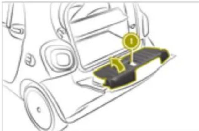
natural_image
Diagram of a car interior showing a seatbelt with a numbered component (no text or symbols)▶ Open the tailgate.
▶ Pull handle ① on the inside of the lower tailgate upwards.
▶ Lift up the cover in the direction of the arrow.
Stowing luggage and large objects
Please note

WARNING
If you stow objects in the vehicle interior an unsuitable way, they could slip or be
thrown around and thus hit vehicle occupants. Additionally, the cup holders, open stowage spaces and mobile phone brackets cannot restrain the objects placed in them in the event of an accident. There is a risk of injury, especially in the event of braking or sudden changes in direction.
• Always stow objects so they cannot be thrown around in these or similar situations.
• Always ensure that objects do not protrude over the top of stowage compartments or ruffled pockets.
- All closable stowage compartments should be closed before beginning your journey.
• Always stow and secure heavy, hard, pointed, sharp-edged, fragile objects or objects which are too large behind the last bench seat or under the passenger seats.
The handling characteristics of a laden vehicle are dependent on the distribution of the load within the vehicle.
Observe the following loading guidelines when loading and transporting luggage and loads:
- never exceed the maximum permissible gross mass or the gross axle weight rating for the vehicle (including occupants) The values are specified on the vehicle identification plate on the B-pillar of the driver's door
- the load must not protrude above the upper edge of the head restraints
- ensure that no items of luggage can enter the passenger compartment above or between the seats
- ensure that loaded objects are stowed safely and are secured
- load heavy objects at the bottom and light objects at the top
- the cargo compartment is the preferred place to stow objects
- stow heavy loads as far forward and as low in down in the cargo compartment as possible
Opening the trunk (smart fortwo coupe)
! The tailgate swings backwards, upwards and downwards when opened. Therefore, make sure that there is sufficient space above, behind and under the tailgate.
▶ Press the 📄 button on the SmartKey.
▶ Fold the upper tailgate up.
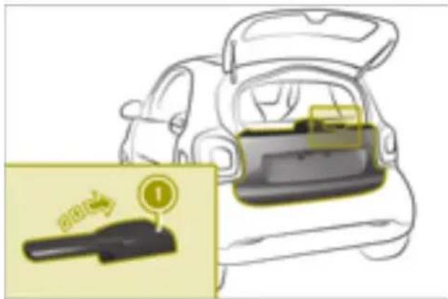
text_image
Diagram showing car interior with a highlighted device and warning label indicating 'No error' or 'Yes'▶ Pull lever ① up.
▶ Fold the lower tailgate down.
Closing the trunk (smart fortwo coupe)
▶ Fold the lower tailgate up and engage on both sides.
▶ Pull the upper tailgate down and press it closed.
▶ Press the 🔒 button on the SmartKey. The vehicle is locked.
Opening the trunk (smart fortwo cabrio)
Opening the tailgate
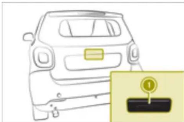
natural_image
Front view of a car with a license plate and a parking tag icon (no text or symbols on the car itself)▶ Press the button on the SmartKey.
▶ Press button ① in the handle recess.
▶ Fold down the tailgate.
Opening the rear soft top
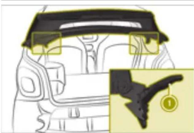
natural_image
Diagram of a car interior showing steering wheel and dashboard, with an inset close-up highlighting the steering wheel (no text or symbols present)▶ Open the tailgate.
▶ Press both latch levers ①.
▶ Swing the rear soft top up.
Closing the trunk (smart fortwo cabrio)
Closing the rear soft top
! If you close the tailgate, you must first lock the rear soft top. Otherwise, the latch levers may break.
▶ Pull the rear soft top down until it engages.
▶ Lock the rear soft top with both latch levers.
Closing the tailgate
▶ Pull the tailgate up until it engages.
▶ Press the ☐ button on the SmartKey. The vehicle is locked.
Enlarging the cargo compartment: folding the front-passenger seat back-rest forward
Folding down the front-passenger seat backrest (using the lever)
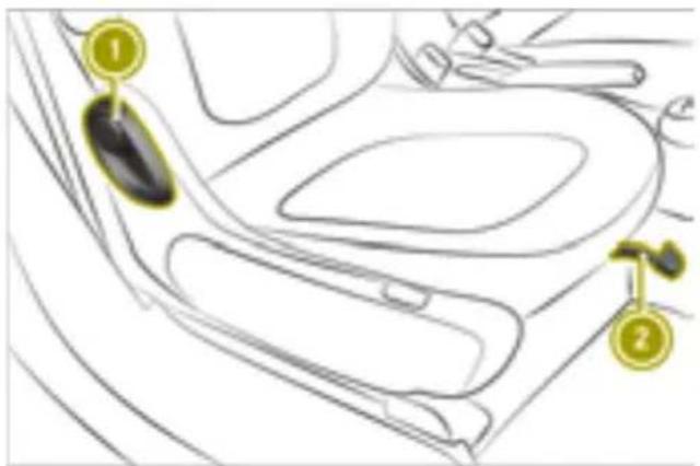
text_image
Diagram of car interior with numbered labels pointing to specific parts, likely for safety or diagnostic reference.Seat with a lever
▶ Lift lever ② and slide the front passenger seat to its rearmost position.
▶ Pull lever ① forward.
▶ Fold the seat backrest forward at the same time.
Folding down the front-passenger seat backrest (using the handwheel)
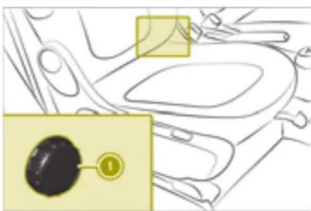
natural_image
Diagram of a car interior with highlighted components and a numbered annotation (no readable text or symbols)Seat with a handwheel
▶ Turn handwheel ① forward.
Folding back the front-passenger seat backrest
Please note

WARNING
If the seat backrest is not engaged, it may fold forwards, e.g. during braking or in the event of an accident.
- As a result, a backrest which is not engaged would press you into the seat belt. The seat belt can no longer offer the intended level of protection and can even cause injuries.
- The backrest cannot restrain objects or loads in the trunk.
There is an increased risk of injury.
Before every journey, make sure that the backrest is engaged as described.
Folding back the front-passenger seat backrest (using the lever)
▶ Pull lever ①.
▶ Push the seat backrest back at the same time until it engages.
Folding back the front-passenger seat backrest (using the handwheel)
▶ Turn handwheel ① back.
Using the trunk partition
Installing the trunk partition

WARNING
The trunk cover alone cannot retain or secure any heavy objects, items of luggage or heavy loads. You may be struck by unsecured loads in the event of sudden changes in direction, braking or an accident. There is a risk of injury or even fatal injury.
Always stow objects in such a way that they cannot be thrown around. Secure objects, luggage or loads by, for example, lashing them down to prevent them from
slipping or tipping over, even if you use the Hooking and unhooking the trunk part trunk cover.
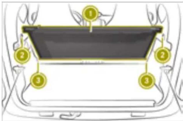
text_image
Diagram showing a car interior with numbered components, likely illustrating a vehicle or dashboard layout.For easier installing, fold the front-passenger seat backrest forward.
▶ smart fortwo coupe: open the upper and lower tailgate.
▶ smart fortwo cabrio: open the lower tail-gate.
▶ smart fortwo cabrio: fold the rear soft top up.
▶ Hold trunk partition ① with the parcel net bag in the direction of the passenger compartment in the trunk.
▶ Insert the trunk partition into bracket ② on the right side.
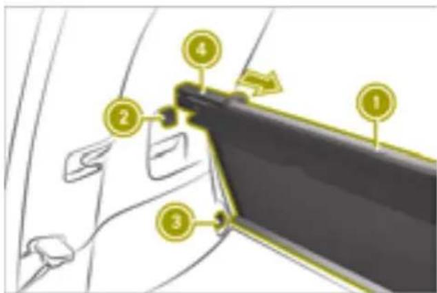
text_image
Diagram of a car door handle with numbered parts and directional arrow indicating movement or assembly▶ Slide handle ④ to the right and hold.
▶ Insert the trunk partition into bracket ② on the left side.
▶ Release handle.
Trunk partition ① snaps into place.
- Secure the parcel net bag with the Velcro fasteners.
If the trunk partition is not required and no subwoofer is installed, it can be attached to brackets ③.
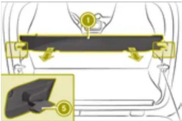
text_image
Diagram illustrating a seatbelt usage technique with labeled parts 1 and 3, showing hand positioning and movement arrows.▶ Grip trunk partition ① in the center and pull it back.
▶ Hook trunk partition into left and right rear brackets ⑤.
Removing/installing the charging cable bag
Removing the charging cable bag
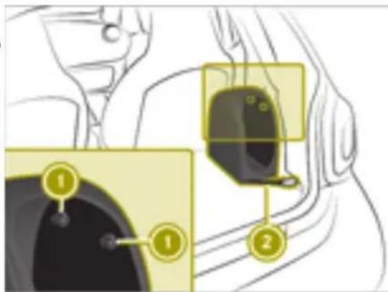
text_image
Diagram showing car interior components with numbered labels pointing to different parts of the seat or vehicle.▶ Turn both buttons ① to the left.
The buttons are released from the anchorage.
▶ Fold the charging cable bag to the left. The Velcro fasteners under the charging cable bag are detached.
▶ Remove snap hook ②.
Installing the charging cable bag
▶ Place the charging cable bag with its side resting on the engine compartment cover and then position it on the side trim.
▶ Position the charging cable bag in a vertical position.
Take hold of the Velcro fasteners beneath the charging cable bag.
▶ Push both buttons ① into the anchorage and turn them to the right.
▶ Secure snap hook ②.
Observing the tire and loading information
Instruction labels for tires and loads

WARNING
Overloaded tires can overheat, causing a blowout. Overloaded tires can also impair the steering and driving characteristics and lead to brake failure. There is a risk of accident.
Observe the load rating of the tires. The load rating must be at least half of the GAWR of your vehicle. Never overload the tires by exceeding the maximum load.
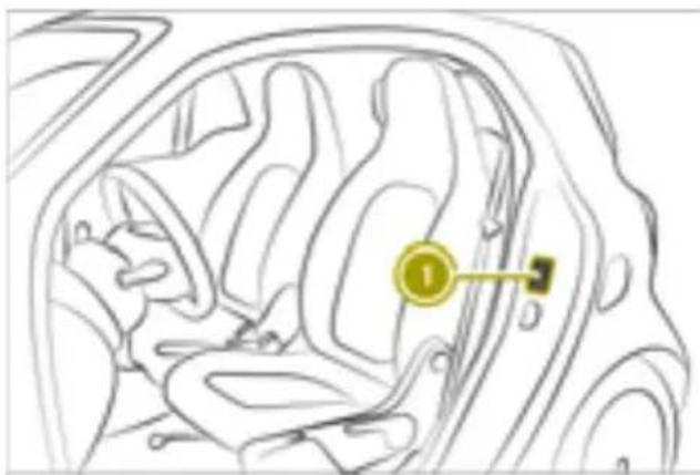
natural_image
Line drawing of a car interior showing seatbelt and dashboard (no text or symbols)① Information tables on the pillar on the driver's side (B-pillar)
Two instruction labels on the vehicle show the maximum possible load.
(1) The Tire and Loading Information placard is on the B-pillar on the driver's side. The Tire and Loading Information placard shows the maximum permissible number of occupants and the maximum
permissible vehicle load. It also contains details of the tire sizes and corresponding pressures for tires installed at the factory.
(2) The vehicle identification plate is on the B-pillar on the driver's side. The vehicle identification plate informs you of the gross weight capacity, called the Gross Vehicle Weight Rating. The Gross Vehicle Weight Rating is made up of the vehicle weight and the load. It also informs you of the front and rear axle weight capacity, called the Gross Axle Weight Rating. The maximum Gross Axle Weight Rating is the maximum weight that can be carried by one axle (front or rear axle). Never exceed the Gross Vehicle Weight Rating or the maximum Gross Axle Weight Rating for the front or rear axle.
Maximum Gross Vehicle Weight Rating
The specification for the maximum Gross Vehicle Weight Rating is listed in tire and loading information table ①: "The combined weight of occupants and cargo should never exceed XXX kilograms or XXX lbs."
The specifications shown on the Tire and Loading Information placard in the illustration are examples. The maximum Gross Vehicle Weight Rating is vehicle-specific and may differ from that in the illustration. The specification for the maximum Gross Vehicle Weight Rating is listed in the tire and loading information table.
Number of seats
Maximum number of seats ① in the Tire Loading Information placard, indicates the maximum number of occupants allowed to travel in the vehicle.
and luggage load capacity is 650 lbs (1400 - 750 (5 x 150) = 650 lbs).
▶ Step 5: Determine the combined weight of luggage and cargo being loaded on the vehicle. That weight may not safely exceed the available cargo and luggage load capacity calculated in step 4.
Example: steps 1 to 3
The following table shows examples on how to calculate total and cargo load capacities with varying seating configurations and number and size of occupants. The following examples use a load limit of 1500 lbs (680 kg). This is for illustration purposes only. Make sure you are using the actual load limit for your vehicle stated on your vehicle's Tire and
i The specifications shown on the Tire and Loading Information placard in the illustration are examples. The number of seats is vehicle-specific and can differ from the details shown. The number of seats for your vehicle can be found on your vehicle's tire and loading information table.
Determining the correct load limit
The following steps have been developed as required of all manufacturers under Title 49 Code of U.S. Federal Regulations, Part 575 pursuant to the "National Traffic and Motor Vehicle Safety Act of 1966".
▶ Step 1: Locate the statement "The combined weight of occupants and cargo should never exceed XXX kg or XXX lbs." of your vehicle's tire and loading information table.
▶ Step 2: Determine the combined weight of Step 2 the driver and passengers that will be rid-ing in your vehicle.
▶ Step 3: Subtract the combined weight of the driver and passengers from XXX kg or XXX lbs.
▶ Step 4: The resulting figure equals the available amount of cargo and luggage load capacity. For example: at a sum "XXX of 1400 lbs and five occupants each weighing 150 lbs, the amount of available cargo
| e's | Example 1 | Example 2 | Example 3 |
| Combined maximum weight of occu-pants and cargo (data from the Tire and Loading Information placard) | 1500 lbs (680 kg) | 1500 lbs (680 kg) | 1500 lbs (680 kg) |
| Example 1 | Example 2 | Example 3 | |
| Number of people in the vehicle (driver and occupants) | 5 3 1 | ||
| Distribution of the occupants | Front: 2Rear: 3 | Front: 1Rear: 2 | Front: 1 |
| Weight of the occu-pants | Occu-pant 1: 150 lbs (68 kg)Occu-pant 2: 180 lbs (82 kg)Occu-pant 3: 160 lbs (73 kg)Occu-pant 4: 140 lbs (63 kg)Occu-pant 5: 120 lbs (54 kg) | Occu-pant 1: 200 lbs (91 kg)Occu-pant 2: 190 lbs (86 kg)Occu-pant 3: 150 lbs (68 kg) | Occu-pant 1: 150 lbs (68 kg) |
| Gross weight of all occu-pants | 750 lbs (340 kg) | 540 lbs (245 kg) | 150 lbs (68 kg) |
Step 3
| Example 1 | Example 2 | Example 3 | |
| Permissible load (maximum Gross Vehicle Weight Rating from the Tire and Loading Information placard minus the gross weight of all occupants) | 1500 lbs (680 kg) -750 lbs (340 kg) = 750 lbs (340 kg) | 1500 lbs (680 kg) -540 lbs (245 kg) = 960 lbs (435 kg) | 1500 lbs (680 kg) -150 lbs (68 kg) = 1350 lbs (612 kg) |
Vehicle identification plate
Even if you have calculated the total load carefully, you should still make sure that the Gross Vehicle Weight Rating and the Gross Axle Weight Rating are not exceeded. Details can be found on the vehicle identification plate on the pillar on the driver's side (B-pillar).
Gross Vehicle Weight Rating: the gross weight of the vehicle, all passengers, load and trailer load/noseweight (if applicable) must not exceed the permissible gross vehicle weight.
Gross Axle Weight Rating: the maximum permissible weight that can be carried by one axle (front or rear axle).
To ensure that the vehicle does not exceed the maximum permissible values (Gross Vehicle Weight Rating and Gross Axle Weight Rating), have your loaded vehicle (including driver, passengers, load and full trailer load, if applicable) weighed on a suitable vehicle weighbridge.
Useful information
The engine compartment in the smart is located at the rear, below the trunk. The rel- ervoirs for service fluids are located under the service cover at the front.
When working on the vehicle, always comply with all safety regulations. Always have work in the engine compartment carried out at a qualified specialist workshop.
- Insert the connector.
- Place the subwoofer at the base of the side trim.
▶-Turn quick-release fastener ① upwards.
▶ Press the bracket into the recess in side trim ②.
▶ Turn quick-release fastener ① clockwise.
Opening and closing the service cover
Removing/installing the subwoofer
Removing the subwoofer
natural_image
Diagram showing a hand pressing a button on a car seat, with an inset close-up highlighting the button (no text or symbols present)▶ Release quick-release fastener ① in the direction of the arrow.
▶ Reach into the recess on the quick-release fastener.
▶ Detach, tilt and pull the subwoofer to the right.
▶ Pull out the connector.
Installing the subwoofer
text_image
Diagram showing a hand holding a car seatbelt with a numbered component labeled '2' and a yellow checkmark icon.Please note

WARNING
If the service cover is not locked, it may come loose during driving and block your view or endanger other road users. There a risk of an accident and injury.
Therefore, make sure that the service covers is locked before every journey.

WARNING
If the windshield wipers begin to operate while the service cover is open, there is a danger of injury from the wiper arms. There is a risk of injury.
Always switch off the windshield wipers and the ignition before opening the service cover.
! To ensure unhindered air intake, carefully remove any snow or dirt from the ventilation slots above the service cover.
The vehicle must be secured against rolling away.
On vehicles with a lockable service cover, the service cover must be unlocked before it is opened.
Unlocking the service cover
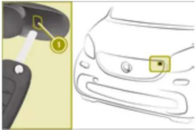
natural_image
Diagram showing a car's side profile with a highlighted key and a close-up of the front wheel (no text or symbols present)▶ Insert the tip of the SmartKey into the opening of lock cover ①.
▶ Press the SmartKey to the right to lever the lock cover.
▶ Remove the lock cover.
▶ Insert the SmartKey into the lock and turn it 90° clockwise.
Opening the service cover
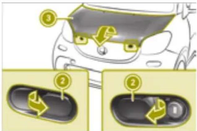
text_image
Diagram illustrating car door panel cleaning steps with numbered instructions and directional arrows▶ Pull both levers ② in the direction of the arrow.
▶ Lift service cover ③ at the front.
▶ Pull service cover ③ slightly forward and lift it up.
▶ Lean service cover ③ attached by the straps, carefully on the front of the vehicle.
Closing the service cover
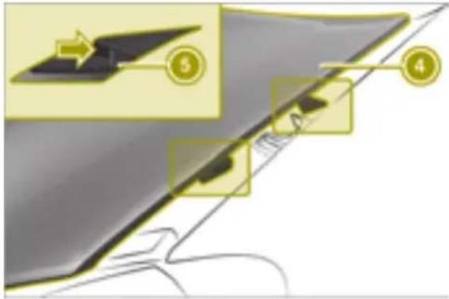
text_image
Diagram illustrating a device component with numbered parts and directional arrows, likely for assembly or labeling.▶ Lift service cover ③.
▶ Slide bars ⑤ on the left and right of the upservice cover under the bars on fender ④.
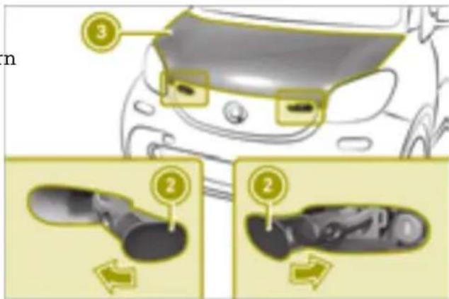
text_image
n ③ ② ②▶ Press service cover ③ down.
▶ Press both levers ② back in the direction of the arrow.
Locking the service cover
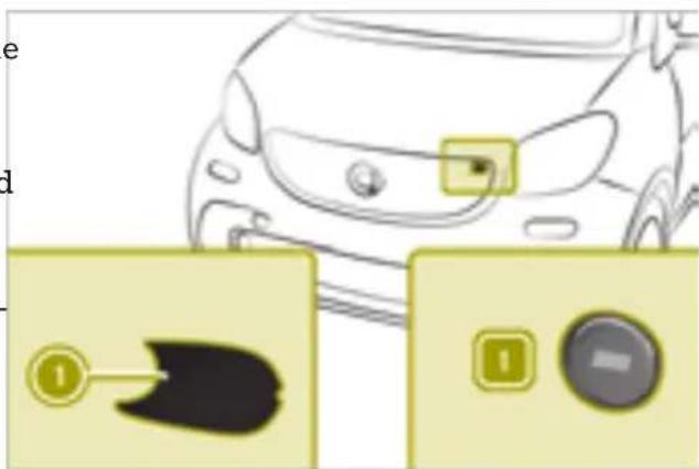
text_image
Diagram showing car front view with control buttons and a close-up of a black object, likely illustrating vehicle safety or diagnostic interface.▶ Insert the SmartKey into the lock and turn it to position 1.
▶ Insert lock cover ① on the driver's side and snap it into place.
Checking and adding service products
Please note

WARNING
Service products may be poisonous and hazardous to health. There is a risk of injury.
Comply with instructions on the use, storage and disposal of service products on the labels of the respective original containers. Always store service products sealed in their original containers. Always keep service products out of the reach of children.

Environmental note
Dispose of service products in an environmentally responsible manner.
Also observe the safety notes in the "Service products" section ( page 186).
Service products include the following:
- Coolant
- Brake fluid
• Windshield washer fluid
• Climate control system refrigerant
Service products approved by smart: http://bevo.mercedes-benz.com
Checking and adding coolant
Checking the coolant level
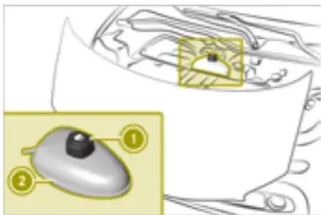
text_image
Diagram showing a computer mouse with labeled parts, including highlighted section and numbered annotations.▶ Stop the vehicle on a level surface.
▶ Let the coolant cool down for at least 30 minutes.
- Open the service cover. - Check reservoir ② visually. The fluid level must be between the MIN mark and the MAX mark.
Adding coolant

WARNING
r- The cooling system is pressurized whentethe drive system is at operating tempera-
ture. When you open the cap, you could be scalded by hot coolant spraying out. There is a risk of injury.
Let the drive system cool down before you open the cap. Wear gloves and eye protection when opening. Open the cap slowly to relieve pressure.
! Only add coolant that has been premixed with the desired antifreeze protection. You could otherwise damage the engine.
Further information on coolants can be found in the Mercedes-Benz Specifications for Service Products, MB BeVo 310.1, e.g. d the Internet at
http://bevo.mercedes-benz.com. Or contact a qualified specialist workshop.
If the coolant has antifreeze protection down to -35^ (-37 ^ ), the boiling point of the coolant during operation is approximately 266 ^ (130 ^ ).
The antifreeze/corrosion inhibitor concentration in the engine cooling system should be 50% -35 °F (-37 °C)). This will protect the engine cooling system against freezing down to around -13 °F (-25 °C).
▶ Cover cap ① of coolant expansion tank ② with a cloth.
▶ Turn the cap slowly one half turn. If necessary, allow excess pressure to escape.
▶ Turn the cap further and remove it.
▶ Refill coolant to the MAX level.
▶ Replace the cap and tighten it as far as it will go.
▶ Close the service cover.
i See "Technical data" for information on recommended coolants.
Adding washer fluid

WARNING
Windshield washer concentrate is highly flammable. If it comes into contact with components in the front compartment, it may ignite. There is a risk of fire and injury.
hot
Make sure that no windshield washer concentrate is spilled next to the filler neck.
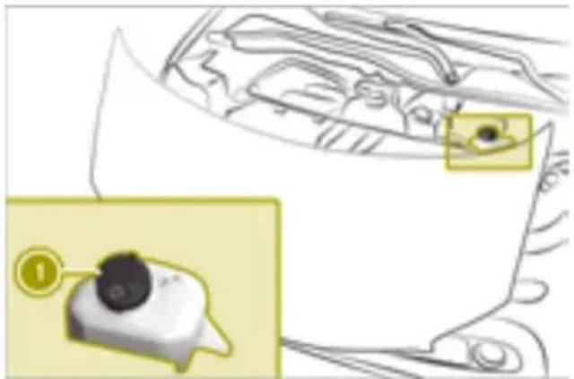
text_image
Diagram showing a car interior with a highlighted eye area and a numbered callout pointing to a device.▶ Open the service cover.
▶ Pull cap ① up at the tab.
▶ If available, pull the removable nozzle up as far as the stop.
▶ Add washer fluid.
▶ If available, push the removable nozzle down and push it inside.
▶ Replace and tightly screw on cap ①.
▶ Close the service cover.
i See "Technical data" for information on windshield washer fluid and antifreeze.
Checking wheels and tires

Warning
A flat tire severely impairs the driving, steering and braking characteristics of the vehicle. There is a risk of an accident.
do not drive with a flat tire. Immediately replace the flat tire with your spare wheel or consult a qualified specialist workshop.

WARNING
Damaged tires can cause tire inflation pressure loss. As a result, you could lose control of your vehicle. There is a risk of accident.
Check the tires regularly for signs of damage and replace any damaged tires immediately.

WARNING
Insufficient tire tread will reduce tire traction. The tire is no longer able to dissipate water. This means that on wet road surfaces, the risk of hydroplaning increases, in particular where speed is not adapted to suit the driving conditions. There is a risk of accident.
If the tire pressure is too high or too low, tires may exhibit different levels of wear at different locations on the tire tread. Thus, you should regularly check the tread depth and the condition of the tread across the entire width of all tires.
Minimum tire tread depth for:
• Summer tires: 18 in (3 mm)
• M+S tires: 16 in (4 mm)
For safety reasons, replace the tires before the legally prescribed limit for the minimum tire tread depth is reached.
! If unavoidable, you should drive over obstacles such as curbs slowly and not at a sharp angle. Otherwise, you may damage the wheels or tires.
Check the wheels and tires for damage at least once a month, as well as after driving off-road or on poorly surfaced roads.
Break in new tires at moderate speeds for the first 60 miles (100 km), as they only reach their full performance after this distance.
Vibrations, audible noises or unusual handling characteristics, e.g. pulling to one side, may indicate that the wheels or tires are damaged.
If you suspect a tire defect:
▶ Reduce vehicle speed.
▶ Stop the vehicle as soon as possible.
▶ Check the wheels and tires for damage. If you find no signs of damage, have the wheels and tires checked at a qualified specialist workshop.
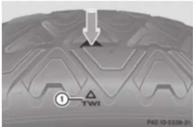
text_image
① TWI P40 10-5338-31pose is to provide drivers with uniform reliable information on tire performance data. Tire manufacturers must grade tires using three performance factors:
① Treadwear grade
② Traction grade
③ Temperature grade
These regulations do not apply to Canada. Nevertheless, all tires sold in North America are provided with the corresponding quality grading markings on the sidewall of the tire.
Quality grades can be found, where applicable, on the tire sidewall between the tread shoulder and maximum tire width.
Example:
• Treadwear grade: 200
• Traction grade: AA
• Temperature grade: A
Indicator ① shows which position the bar marking (arrow) for tread wear is integrate into the tire tread.
Treadwear indicators (TWI) are required by law. Six indicators are positioned on the tire tread. They are visible once a tread depth of approximately 116 in (1.6 mm) has been reached. If this is the case, the tire is so well that it must be replaced.
All passenger car tires must conform to the statutory safety requirements in addition to these grades.
i The actual values for tires are vehicle-specific and may deviate from the values in the illustration.
Obtaining information on tires
Uniform Tire Quality Grading Standards
Overview of Tire Quality Grading Standards
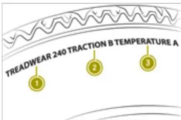
text_image
TREADWEAR 240 TRACTION B TEMPERATURE A 1 2 3Uniform Tire Quality Grading Standards are U.S. government specifications. Their pur-
Treadwear
The treadwear grade is a comparative rating based on the wear rate of the tire when tested under controlled conditions on a specified U.S. government course. For example, a tire graded 150 would wear one and one-half times as well on the government test track as a tire graded 100.
The relative performance of tires depends upon the actual conditions of their use, however, and may depart significantly from the norm due to variations in driving habits, service practices and differences in road characteristics and climate conditions.
Traction

WARNING
The traction grade assigned to this tire is based on straight-ahead braking traction tests, and does not include acceleration, cornering, hydroplaning, or peak traction characteristics.
! Avoid wheelspin. This can lead to damagatory test wheel than the minimum required to the drive train. by law.
The traction grades, from highest to lowest, are AA, A, B and C. These grades represent tire's ability to stop on wet surfaces, as measured under controlled conditions on specified government test surfaces of asphalt and concrete. A tire marked C may have poor traction performance.
The safe speed on a wet, snow covered or icy road is always lower than on dry road surfaces.
The drivers must pay special attention to road conditions when temperatures are around freezing point.
smart recommends a minimum tread depth of 16 in (4 mm) on all four winter tires. The legally required minimum tread depth must be observed. Winter tires can reduce the braking distance on snow-covered surfaces in comparison with summer tires. The braking distance is still much further than on surfaces that are not icy or covered with snow. Therefore take appropriate care when driving.
Temperature

WARNING
The temperature grade for this tire is established for a tire that is properly inflated and not overloaded. Excessive speed, underinflation, or excessive loading, either separately or in combination, can cause excessive heat build-up and possible tire failure.
The temperature grades are A (the highest), B and C. They represent the tire's resistance to the generation of heat and its ability to dissipate heat when tested under controlled conditions on a specified indoor laboratory test wheel. Sustained high temperature can cause the material of the tire to degenerate and reduce tire life, and excessive temperature can lead to sudden tire failure. The grade C corresponds to a level of performance which all passenger car tires must meet under the Federal Motor Vehicle Safety Standard No. 109. Grades B and A represent higher levels of performance on the laborathe
Tire labeling
Overview
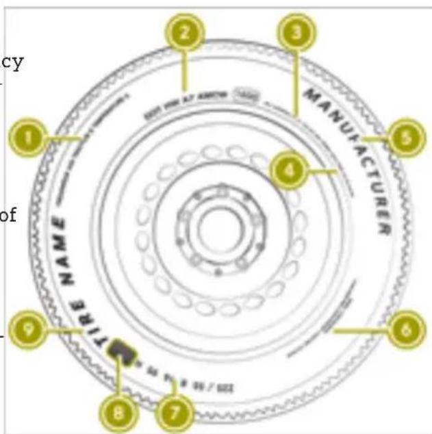
text_image
CY of 1 2 3 MANUFACTURER NAME ORDER 4 5 6 7 8 9① Uniform Tire Quality Grading Standard
② DOT, Tire Identification Number
③ Maximum load rating
④ Maximum tire pressures
⑤ Manufacturer
⑥ Tire material
⑦ Tire size designation, load-bearing capacity and speed rating
⑧ Load index
⑨ Tire name
i Tire data is vehicle-specific and may deviate from the data in the example.
Fire size designation, load-bearing capacity and speed rating

WARNING
Exceeding the stated tire load-bearing capacity and the approved maximum speed could lead to tire damage or the tire bursting. There is a risk of accident.
Therefore, only use tire types and sizes approved for your vehicle model. Observe
the tire load rating and speed rating required for your vehicle.
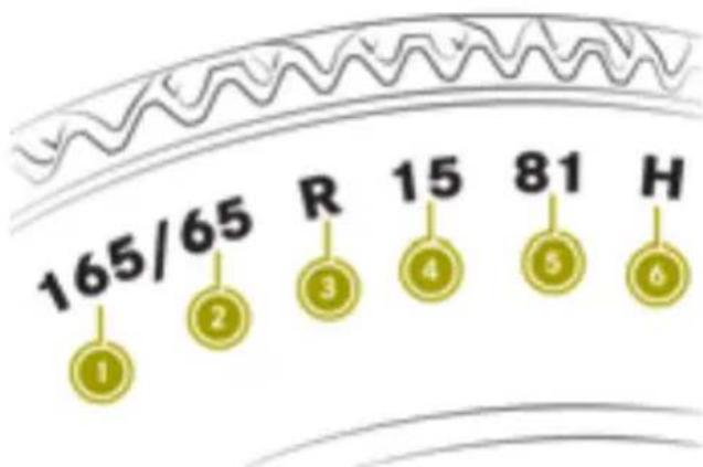
text_image
165/65 R 15 81 H ① ② ③ ④ ⑤ ⑥① Tire width in mm
② Nominal aspect ratio in %
③ Tire code
④ Rim diameter
⑤ Load bearing index
⑥ Speed rating
General information: depending on the manufacturer's standards, the size imprinted in the tire wall may also contain a letter that precedes the size description.
- No letter: passenger vehicle tires according to European manufacturing standards.
- Letter P: passenger vehicle tires according to US manufacturing standards.
- Letters LT: light truck tires according to manufacturing standards.
- Letter T: compact emergency wheels with high tire pressure that are only designed for temporary use in an emergency.
Tire width: tire width ① shows the nominal tire width in millimeters.
Rim diameter: rim diameter ④ is the diameter of the bead seat and is given in inches (in).
Load-bearing index: load-bearing index ⑤ is a numerical code that specifies the maximum load-bearing capacity of a tire. Load-bearing index 91 indicates a maximum load of 1,356 lb (615 kg) that the tires can bear. Do not overload the tires by exceeding the specified load limit. The maximum permissible load is located on the vehicle's Tire and Loading Information placard on the B-pillar on the driver's side.
Speed rating: speed rating ⑥ specifies the approved maximum speed of the tire.
Summer tires
| Index Speed rating |
| Q up to 100 mph (160 km/h) |
| R up to 106 mph (170 km/h) |
| S up to 112 mph (180 km/h) |
| T up to 118 mph (190 km/h) |
| H up to 130 mph (210 km/h) |
| V up to 149 mph (240 km/h) |
| W up to 168 mph (270 km/h) |
| Y up to 186 mph (300 km/h) |
| US ZR...Y up to 186 mph (300 km/h) |
| ZR...(..Y) over 186 mph (300 km/h) |
| ZR over 149 mph (240 km/h) |
Height-width ratio: aspect ratio ② is the size bearing index ⑤ and speed rating ⑥. ratio between the tire height and tire width if the size description of the tire includes and is shown in percent. The aspect ratio is ZR" and there are no service specifications, calculated by dividing the tire width by the contact the tire manufacturer in order to find tire height. out the maximum speed.
Tire code: tire code ③ specifies the tire type of a service specification is available, the maximum speed is limited according to the speed rating in the service specification. Example: 245/40 ZR18 97 Y. In this example, "97 Y" is the service specification. The letter ZR: optional, depending on the manufacturer, for tires with a maximum speed of 186 mph over 149 mph (240 km/h), e.g. 245/40 ZR 18300 km/h).
The size description for all tires with maximum speeds of over 186 mph (300 km/h) must
include "ZR", and the service specification must be given in parentheses. Example:
275/40 ZR 18 (99 Y). Speed rating "(Y)" indicates that the maximum speed of the tire is over 186 mph (300 km/h). Consult the tire manufacturer to find out the maximum speed.
All-weather tires and winter tires
| Index Speed rating | |
| Q M+S5 | up to 100 mph (160 km/h) |
| T M+S5 | up to 118 mph (190 km/h) |
| H M+S5 | up to 130 mph (210 km/h) |
| V M+S5 | up to 149 mph (240 km/h) |
Not all tires with the M+S marking provide the driving characteristics of winter tires. In addition to the M+S marking, winter tires also have the snowflake symbol on the tire wall. Tires with this marking fulfill the requirements of the Rubber Manufacturers Association (RMA) and the Rubber Association of Canada (RAC) regarding the tire traction on snow. They have been especially developed for driving on snow.
An electronic speed limiter prevents the vehicle from exceeding a speed of 130 mph (210 km/h).
The speed rating of tires mounted at the factory may be higher than the maximum speed that the electronic speed limiter permits.
The driver must ensure that the tires have the required speed rating, e.g. with new tires. For the required speed rating for the vehicle, see ( page 134).
Further information about reading tire data is available from any qualified specialist workshop.
Load index
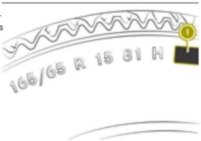
text_image
165/65 R 15 81 HIn addition to the load-bearing index, load identification ① may also be imprinted on the sidewall of the tire.
- No text: standard load (SL) tire.
- XL or Extra Load: extra load or reinforced tire.
Light Load: light load tire.
• C, D, E: load range that depends on the maximum load that the tire can carry at a certain pressure.
Maximum load rating
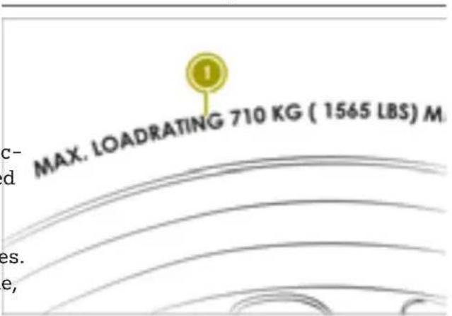
text_image
MAX. LOADRATING 710 KG ( 1565 LBS) M. c- d es. e,Maximum tire load ① is the maximum permissible weight for which the tire is approved.
Do not overload the tires by exceeding the specified load limit. The maximum permissible load is located on the vehicle's Tire and Loading Information placard on the B-pillar on the driver's side.
DOT, Tire Identification Number (TIN)
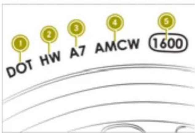
text_image
1 DOT HW A7 AMCW 1600① DOT (Department of Transportation)
② Manufacturer identification code
③ Tire size
④ Tire type code
⑤ Date of manufacture
U.S tire regulations prescribe that every tire manufacturer or retreader must imprint a TIN in or on the sidewall of every tire produced.
The TIN is a unique identification number. The TIN enables the tire manufacturers or retreaders to inform purchasers of recalls and other safety-relevant matters. It makes it possible for the purchaser to easily identify the affected tires.
DOT (Department of Transportation) ① indicates that the tire complies with the requirements of the United States Department of Transportation.
Manufacturer identification code ② provides details on the tire manufacturer. New tires have a code with two symbols. Retreaded tires have a code with four symbols.
Tire type code ④ can be used by the manufacture number of occupants for which the vehi-facturer as a code to describe specific char-ele is designed multiplied by 68 kilograms acteristics of the tire. (150 lbs).
Date of manufacture ⑤ provides information about the age of a tire. The first and second positions represent the week of manufacture starting with "01" for the first calendar week. Positions three and four represent the year's manufacture. For example, a tire that is marked with "3208", was manufactured in week 32 in 2008.
Tire characteristics
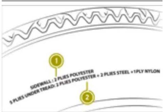
text_image
SIDEWALL : 2 PLIES POLYESTER 5 PLIES UNDER TREAD: 2 PLIES POLYESTER + 2 PLIES STEEL + 1PLY NYLON① Tire cord and the number of layers in the side wall
② Tire cord and the number of layers under the tread
Definition of terms for tires and loading
Tire ply composition and material used
Describes the number of plies or the number of layers of rubber-coated fabric in the tire tread and sidewall. These are made of steel nylon, polyester and other materials.
Bar
Metric unit for tire pressure. 14.5038 pounds per square inch (psi) and 100 kilopascals (kPa) are the equivalent of 1 bar.
DOT (Department of Transportation)
DOT marked tires fulfill the requirements of the United States Department of Transportation.
Normal occupant weight
The number of occupants for which the vehicle is designed multiplied by 68 kilograms (150 lbs).
Uniform Tire Quality Grading Standards
A uniform standard to grade the quality of wires with regards to tread quality, tire traction and temperature characteristics. The quality grading assessment is made by the manufacturer following specifications from the U.S. government. The ratings are molded into the sidewall of the tire.
Recommended tire pressures
The recommended tire pressure applies to the tires mounted at the factory.
The Tire and Loading Information placard contains the recommended tire pressures for cold tires on a fully loaded vehicle and for maximum permissible vehicle speed.
The tire pressure table contains the recommended tire pressure for cold tires under various operating conditions, i.e. loading and speed of the vehicle.
Increased vehicle weight due to optional equipment
The combined weight of all standard and optional equipment available for the vehicle, regardless of whether it is actually installed on the vehicle or not.
Rim
This is the part of the wheel on which the is mounted.
GAWR (Gross Axle Weight Rating)
The GAWR is the maximum gross axle weight rating. The actual load on an axle must not exceed the gross axle weight rating. The maximum gross axle weight rating is located on the vehicle identification plate on the B-pillar on the driver's side.
Speed rating
The speed rating is part of the tire identification. It specifies the speed range for which the tire is approved.
GVW (Gross Vehicle Weight)
The gross vehicle weight includes the weight of the vehicle including tools, the spare wheel, accessories installed, occupants, luggage and the drawbar noseweight, if applicable. The gross vehicle weight must not exceed the gross vehicle weight rating GVW as specified on the vehicle identification plate on the B-pillar on the driver's side.
GVWR (Gross Vehicle Weight Rating)
The GVWR is the gross vehicle weight rating of the fully laden vehicle (weight of the vehicle including all accessories, occupants, luggage and the drawbar noseweight, if applicable). The gross vehicle weight rating is specified on the vehicle identification plate on the B-pillar on the driver's side.
Maximum loaded vehicle weight
The maximum weight is the sum of the following factors:
• the curb weight of the vehicle
• weight of accessories
• the load limit
- the weight of the factory installed optional equipment
Kilopascal (kPa)
Metric unit for tire pressure. 6.9 kPa corresponds to 1 psi. Another unit for tire pressure is bar. 100 kilopascals (kPa) are the equivalent of 1 bar.
Load index
In addition to the load-bearing index, the load index may also be imprinted on the sidewall of the tire. This specifies the load-bearing capacity of the tire more precisely.
Curb weight
The weight of a vehicle with standard equipment including the maximum capacity of coolant. It also includes the climate control system and optional equipment if your vehicle is equipped with these, but does not include passengers or luggage.
Maximum load rating
The maximum load rating is the maximum permissible weight in kilograms or pounds for which a tire is approved.
Maximum permissible tire pressure
Maximum permissible tire pressure for one tire.
Maximum load on one tire
Maximum load on one tire. This is calculated by dividing the maximum axle load of one axle by two.
PSI (pounds per square inch)
A standard unit of measure for tire pressure.
Aspect ratio
Relationship between tire height and tire width in percent.
Tire pressure
Traction
This is pressure inside the tire applying anTraction is the result of friction between the outward force to each square inch of the times and the road surface.
surface. The tire pressure is specified in pounds per square inch (psi), in kilopascal
(kPa) or in bar. The tire pressure should be corrected when the tires are cold.
Cold tire pressure
The tires are considered to be cold in the following conditions:
- If the vehicle has been parked with the tires out of direct sunlight for at least three hours.
- If the vehicle has not been driven further than 1 mile (1.6 km)
Tread
The part of the tire that comes into contact with the road.
Bead
The tire bead ensures that the tire sits securely on the wheel. There are several st-wires in the bead to prevent the tire from coming loose from the wheel rim.
Sidewall
The part of the tire between the tread and bead.
Weight of optional extras
The combined weight of those optional extra that weigh more than the replaced standard parts and more than 5 lbs (2.3 kilograms). These optional extras, such as high-performance brakes, level control, a roof rack of a high-voltage battery, are not included in the curb weight and the weight of the accessories.
TIN (Tire Identification Number)
This is a unique identifier which can be used by a tire manufacturer to identify tires, for example for a product recall, and thus identify the purchasers. The TIN is made up of manufacturer's identity code, tire size, tire type code and the manufacturing date.
Load bearing index
The load-bearing index is a code that contains the maximum load bearing capacity of a tire.
Treadwear indicators
Narrow bars (tread wear bars) that are distributed over the tire tread. If the tire tread is level with the bars, the wear limit of 116 in (1.6 mm) has been reached.
Occupant distribution
The distribution of occupants in a vehicle at their designated seating positions.
Total load limit
Nominal load and luggage load plus 68 kg (150 lbs) multiplied by the number of seats in the vehicle.
Changing a wheel
Please note

WARNING
Interchanging the front and rear wheels may severely impair the driving characteristics if the wheels or tires have different dimensions. The wheel brakes or suspension components may also be damaged. There is a risk of accident.
Rotate front and rear wheels only if the wheels and tires are of the same dimensions.

WARNING
sIf wheels and tires of the wrong size are used, the wheel brakes or suspension components may be damaged. There is a risk of an accident.
Always replace wheels and tires with those that fulfill the specifications of the original part.
When replacing wheels, make sure to use the correct:
- designation
- model
When replacing tires, make sure to use the correct: The service life of tires depends on various factors, including the following:
- designation
- manufacturer
-
model
-
Driving style
- Tire pressure
- Distance covered
Observe the following rules for selecting new tires:
! If your vehicle is equipped with the tire pressure monitor, each wheel has an electronic component.
Tire-mounting tools should not be applied in the area of the valve. Otherwise, the electronic components could be damaged. Only have tires replaced at a qualified specialist workshop.
- Only mount tires and wheels of the same type and make.
- Only tires of the same size may be used on a single axle (left/right).
- Only use tires of the same type (summer tires, all-season tires, winter tires).
- Use only wheel/tire combinations approved by smart.
! Position a suitable jack only on the jacking points intended for this purpose. Raise the vehicle for a short time only to change the wheel. Make sure the vehicle is on a suitable surface and that no-one is in the vehicle. Secure the vehicle using chocks and apply the parking brake.
Do not wear tires out too much. as this significantly reduces the traction on wet roads (hydroplaning).
- Replace tires after six years at the latest.
Recommended tire pressure for various operating states can be found on the tire pressure table on the door pillar (B-pillar) on the driver's side.
Rules for selecting new tires
! For safety reasons, smart recommends that you only use tires and wheels which have been specifically approved by smart for your vehicle. These are specially adapted to the control systems, such as ABS or ESP®.
You can find further information regarding tires at specialist tire retailers, at qualified specialist workshops or at any smart center.
Preparing to change a wheel
The vehicle tool tray is located under the glove box.
Only use tires and wheels specifically tested and approved by smart. Certain characteristics, e.g. handling, vehicle noise emissions or fuel consumption, may otherwise be adversely affected. In addition, when driving with a load, dimensional variations and different tire deformation characteristics could cause the tires to make contact with the bodywork and axle components. This could result in damage to the tires or the vehicle.
smart accepts no liability for damage resulting from the use of tires or wheels other than those tested and approved.
Information on wheels and tires can be obtained at a qualified specialist workshop, e.g. a smart center.
▶ Stop the vehicle on solid, non-slippery and level ground.
▶ Apply the parking brake.
▶ Position the front wheels to point straight ahead.
▶ Shift the transmission to position P.
▶ Switch off the engine.
▶ Remove SmartKey from ignition lock.
▶ Secure the vehicle against rolling away.
Removing a wheel
WARNING
If you do not position the jack correctly at the appropriate jacking point of the vehi-
cle, the jack could tip over with the vehicle raised. There is a risk of injury.
Only position the jack at the appropriate jacking point of the vehicle. The base of the jack must be positioned vertically, directly under the jacking point of the vehicle.
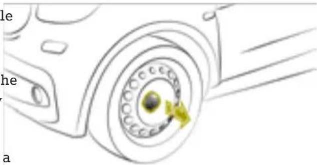
text_image
le he a! Do not place wheel bolts in sand or on a dirty surface. The bolt and wheel hub threads could otherwise be damaged when you screw them in.
! Position a suitable jack only on the jacking points intended for this purpose.
Never position the jack on the high-voltage battery. Do not jack up the vehicle on the high-voltage battery. There is otherwise a risk of damaging the high-voltage battery.
Also observe the notes in the "Changing a wheel" section.
Vehicles with steel wheels and hub cap covers:
▶ Remove the wheel hub cover.
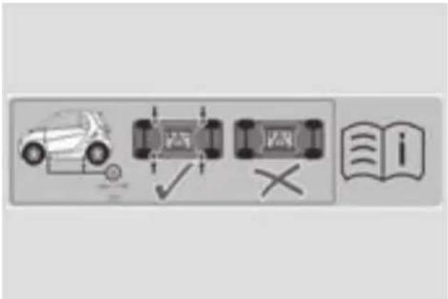
text_image
Diagram showing car ownership and vehicle inspection with checkmark and cross symbols, alongside an open book icon labeled 'i'Warning stickers
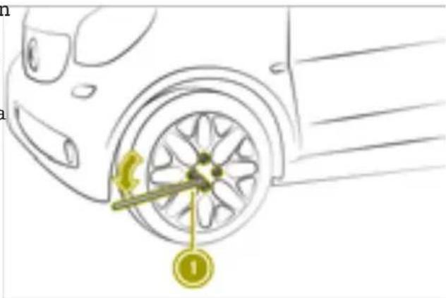
text_image
Diagram of a car wheel with a labeled sensor or sensor device and a numbered marker indicating the component.▶ Using lug wrench ① loosen the wheel bolts by about one turn. Do not unscrew the wheel bolts completely.

natural_image
Line drawing of a car wheel with a yellow brake caliper (no text or symbols)Vehicles with steel wheels and hub caps:
▶ Using both hands, grasp two hub cap openings and remove the hub cap.
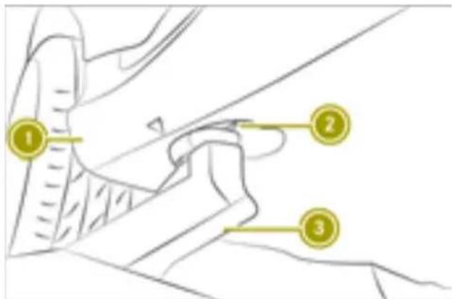
text_image
Diagram showing three labeled parts of a mechanical or architectural component, with numbered annotations pointing to specific features.The vehicle may only be raised at the designated jacking points. Points ② are to the front and back in the immediate vicinity of the wheels. Do not position jack ③ on the edge of sill ①. Otherwise, damage to the vehicle could occur.
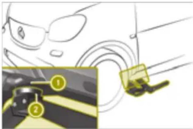
natural_image
Illustration of a car with glasses and a highlighted interior area showing a vehicle (no text or symbols)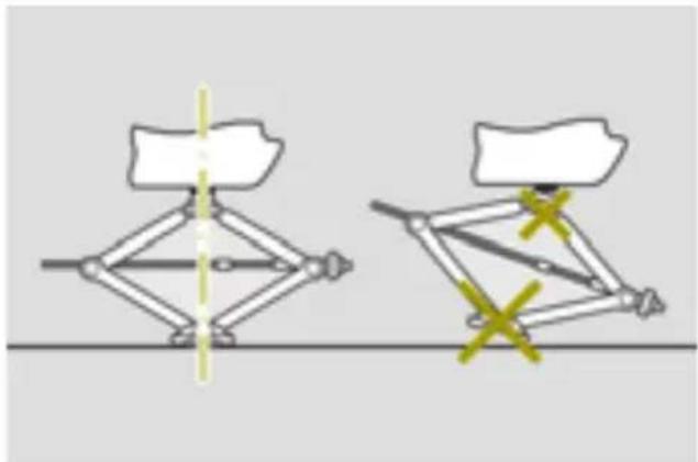
natural_image
Diagram showing two mechanical linkage configurations with yellow X marks indicating joint or connection points (no text or symbols present)▶ Position jack ② behind the triangular indentations for jacking point ① on the longitudinal body member.
▶ Set the foot of the jack up vertically with respect to the jacking point on the vehicle.
▶ Raise the vehicle using the jack until the tire is a maximum of 1.2 in (3 cm) off the ground.
▶ Unscrew and remove the wheel bolts.
▶ Remove the wheel.
Mounting a wheel

WARNING
The wheels could work loose if the wheel nuts and bolts are not tightened to the specified tightening torque. There is a risk of accident.
Have the tightening torque immediately checked at a qualified specialist workshop after a wheel is changed.

WARNING
If you tighten the wheel bolts or wheel nuts when the vehicle is raised, the jack could tip over. There is a risk of injury.
Only tighten the wheel bolts or wheel nuts when the vehicle is on the ground.
! When changing a wheel, use only wheel bolts that have been approved for the wheel rim and vehicle.
! To prevent damage to the paintwork, hold the wheel securely against the wheel hub while screwing in the first wheel bolt.
Always pay attention to the instructions and safety notes on "Changing a wheel" (▷ page 139).
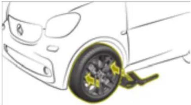
natural_image
Line drawing of a car wheel with a yellow brake pad, showing no text or symbolsMount tires with a specified direction of rotation only according to their direction of rotation. An arrow on the sidewall of the tire indicates its correct direction of rotation.
▶ Clean the wheel and wheel hub contact surfaces.
▶ Push the wheel onto the wheel hub and press it on.
▶ Screw in the wheel bolts and tighten them slightly.
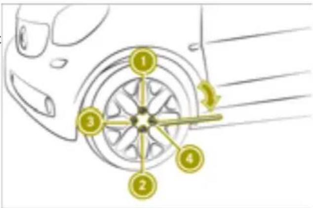
text_image
Diagram showing car wheel alignment with numbered components and directional arrow indicating rotation or movement▶ Lower the vehicle all the way.
▶ Remove the jack.
▶ Tighten the wheel bolts evenly in a cross wise pattern in sequence indicated ① to ④. The tightening torque must be 77 lb-ft (105 Nm).
▶ Check the recommended tire pressure and adjust if necessary.
i Vehicles with tire pressure monitor: all wheels mounted must be equipped with functioning sensors.

text_image
Diagram showing car wheel and car interior with numbered annotations indicating parts of the wheel and a highlighted section.Vehicles with steel wheels and hub caps:
▶ Mount hub cap ⑤ such that valve ⑥ does not become trapped.
▶ Press the hub cap evenly onto the wheel with both hands until you hear the hub engage.
▶ Check to make sure the hub cap is seated securely on the wheel.
Vehicle with steel wheels and wheel hub covers:
▶ Mount the wheel hub cover.
Storing wheels
▶ Store wheels in a cool, dry and dark place when not in use.
▶ Protect against oil, grease and fuel.
Using the tire pressure monitor
Useful information
i This function is only available in the US
WARNING
Each tire, including the spare (if provided), should be checked at least once every two weeks when cold and inflated to the pressure recommended by the vehicle manufacturer on the Tire and Loading Information placard on the driver's door B-pillar or the tire pressure label on the inside of the fuel filler flap. If your vehicle has tires of a different size than the size indicated on the Tire and Loading Information placard or, if available, the tire pressure label, you should determine the proper tire pressure for those tires.
As an added safety feature, your vehicle has been equipped with a tire pressure monitoring system (TPMS) that illuminates a low tire pressure telltale when one or more of your tires are significantly under inflated. Accordingly, when the low tire pressure telltale lights up, you should sto and check your tires as soon as possible, and inflate them to the proper pressure. Driving on a significantly underinflated tire causes the tire to overheat and can pad to tire failure.
Underinflation also reduces fuel efficiency and tire tread life, and may affect the vehicle's handling and stopping ability. Please note that the TPMS is not a substitute for proper tire maintenance, and it is the driver's responsibility to maintain correct tire pressure, even if underinflation has not reached the level to trigger illumination of the TPMS low tire pressure telltale.
Your vehicle has also been equipped with a TPMS malfunction indicator to indicate when the system is not operating properly. The TPMS malfunction indicator is combined with the low tire pressure telltale. When the system detects a malfunction, the warning lamp will flash for approximately a minute and then remain continuously illuminated. This sequence will be repeated every time the vehicle is started as long as the malfunction exists. When the malfunction indicator is illuminated, the
system may not be able to detect or signal low tire pressure as intended.
TPMS malfunctions may occur for a variety of reasons, including the installation of incompatible replacement or alternate tires or wheels on the vehicle that prevent the TPMS from functioning properly.
Always check the TPMS malfunction tell-tale after replacing one or more tires or wheels on your vehicle to ensure that the replacement or alternate Tires and wheels allow the TPMS to continue to function properly.
▶ Select yes and press OK to confirm. The display shows the Tire Pressure Monitor Restarted message.
▶ Press OK to confirm.
If the Tire Pressure Monitor Restarted message does not appear after 5 seconds, repeat the tire pressure monitor restart.
Checking the tire pressures
Please note

WARNING
Underinflated or overinflated tires pose
It is the driver's responsibility to set the tirehe following risks:
pressure to that recommended for cold tires which is suitable for the operating situation.
The tire pressure monitor issues a warning when the pressure drops in one or more of tires.
The tire pressure monitor only functions if sensors are present in all four tires, and of the monitor has learned the correct tire pressure for the current operating situation. This occurs automatically in most situations, but
may also be specified after restarting the tire pressure monitor. Before restarting, check the tires for the recommended tire pressure.
The tire pressure monitor does not provide a warning in the following cases:
• Even loss of pressure on multiple tires
- Sudden loss of tire pressure, e.g. due to penetration by a foreign body
- Incorrectly set tire pressure
The tire pressure monitor has a yellow warning lamp in the instrument cluster for indicating pressure loss and malfunction.
- the tires may burst, especially as the load and vehicle speed increase.
the tires may wear excessively and/or unevenly, which may greatly impair tire traction.
ter the driving characteristics, as well as steering and braking, may be greatly impaired.
There is a risk of an accident.
Follow recommended tire inflation pressures and check the pressure of all the tires including the spare wheel:
• monthly, at least
- if the load changes
• before beginning a long journey
• under different operating conditions, e.g. off-road driving
If necessary, correct the tire pressure.
Restarting the tire pressure monitor
▶ Set the tire pressure of all tires to the recommended value.
▶ Select Settings TiTirerResessureMonitor in the on-board computer.
The Tire Pressure Monitor Use current pressures as new reference values? message appears in the display.

WARNING
If you mount unsuitable accessories onto tire valves, the tire valves may be overloaded and malfunction, which can cause tire pressure loss. Due to their design, retrofitted tire pressure monitoring systems will keep the tire valve open. This can also result in tire pressure loss. There is a risk of an accident.
Only screw standard valve caps or valve caps specifically approved for your vehicle by smart onto the tire valve.
The tire pressure table is on the inside of the socket flap.

WARNING
If the tire pressure drops repeatedly, the wheel, valve or tire may be damaged. Tire pressure that is too low may result in a tire blow-out. There is a risk of an accident.
- Check the tire for foreign objects.
- Check whether the wheel is losing air or the valve is leaking.
If you are unable to rectify the damage, contact a qualified specialist workshop.
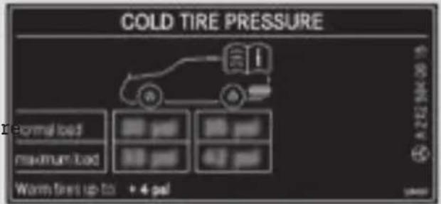
text_image
COLD TIRE PRESSURE Normal load Maximum load Warm fires up to 4 psi A222 M4036Example: tire pressure table for all tires permitted for this vehicle by the factory
The tire pressure table contains the recom-The recommended tire pressures for the tire intended pressures for cold tires for various mounted at the factory can be found on the operating conditions, i.e. differing load and labels described here. speed conditions.
Further information is available in qualified specialist workshops.
The specifications on the sample Tire and Loading Information placard and tire pressure tables are examples. Tire pressure specifications are vehicle-specific and may deviate from the data shown here. The valid tire pressure value can be found on the Tire and Loading Information placard and the vehicle's tire pressure table.
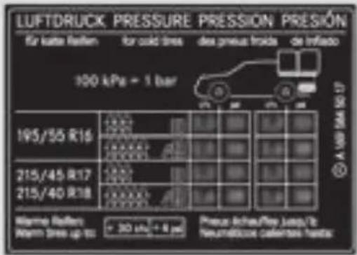
text_image
LUFTDRUCK PRESSURE PRESSION PRESION für kalle flatten for cold lines des presus froids de inflasto 100 kPa = 1 bar 195/55 R16 215/45 R17 215/40 R18 Warme flatten Warm lines up to: 300 psi + 8 psi Presur-Inchau/Res Jump/Tz Neurettricose calentera heater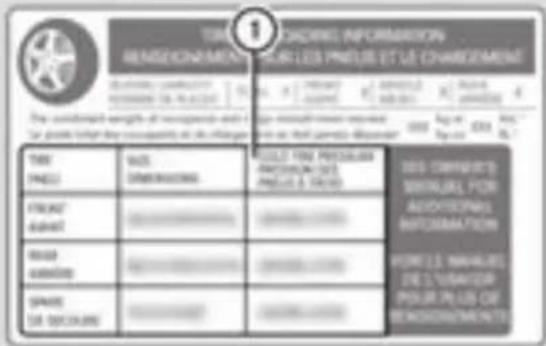
text_image
TIRE CHADRIE INFORMATION SENSIGNEMENT ET LAIR LES PHELIS ET LE CHARGEMENT THE COMPARATE PRESIDENT DES PHELIS ET LAIR 1.1 2.2 3.3 4.4 5.5 6.6 7.7 8.8 9.9 10.0 11.1 12.2 13.3 14.4 15.5 16.6 17.7 18.8 19.9 20.0 21.1 22.2 23.3 24.4 25.5 26.6 27.7 28.8 29.9 30.0 31.1 32.2 33.3 34.4 35.5 36.6 37.7 38.8 39.9 40.0 41.1 42.2 43.3 44.4 45.5 46.6 47.7 48.8 49.9 50.0 51.1 52.2 53.3 54.4 55.5 56.6 57.7 58.8 59.9 60.0Example: tire pressure table with tire dimensions
If a tire size precedes a tire pressure, the tire pressure information following is only valid for that tire size. The load conditions "partially laden" and "fully laden" are defined in the table for different numbers of occupants and amounts of luggage. The actual number of seats may differ.
① Recommended tire pressures
The Tire and Loading Information placard is on the door pillar on the driver's side (B-pillar).
The Tire and Loading Information placard contains the recommended tire pressures for cold tires. The recommended tire pressures are valid for the maximum permissible load and up to the maximum permissible vehicle speed.
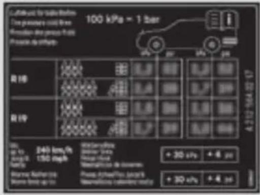
text_image
Fuel used for fuel efficiency 100 kPa = 1 liter Fuel parameters: solid lines Reposition line price per mile Provision for mpg R10 R19 240 km/h 150 m³/h Water/Flame water level Water flow Water/Flame ratio Water/Flame load + 30 s/h + 6 s/h + 30 s/h + 6 s/hSome tire pressure tables only show the rim diameter instead of the complete tire size, e.g. R18. The rim diameter is part of the tire size and can be found on the tire sidewall. If the tire pressures have been set to the lower values for lighter loads and/or lower speeds, correct them in the following cases:
- If you are driving with a heavier load - If you are driving at higher speeds
The tire pressure recommended for increased loads and higher speeds in the tire pressure table can affect driving comfort.
If the tire pressure is not set correctly, this can lead to an excessive build up of heat and a sudden loss of pressure.
Underinflated or overinflated tires

WARNING
Tires with pressure that is too low can overheat and burst as a consequence. In addition, they also suffer from excessive and/or irregular wear, which can severely impair the braking properties and the driving characteristics. There is a risk of an accident.
Avoid tire pressures that are too low in all the tires, including the spare wheel.

WARNING
Tires with excessively high pressure can burst because they are damaged more easily by road debris, potholes etc. In addition, they also suffer from irregular wear, which can severely impair the braking
properties and the driving characteristics. There is a risk of an accident.
Avoid tire pressures that are too high in all the tires, including the spare wheel.
Possible consequences of underinflated tires:
- Tire defects as a result of overheating
- Adverse effect on handling characteristics
- Quick and uneven wear
- Adverse effect on energy consumption
Possible consequences of overinflated tires:
- Longer braking distance
- Adverse effect on handling characteristics
- Quick and uneven wear
- Adverse effect on driving comfort
- Increased susceptibility to damage
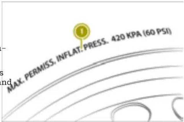
text_image
MAX. PERMISS, INFLAT. PRESS. 420 KPA (60 PSI)① Example: maximum permissible tire pressure
Do not exceed the maximum permissible tire inflation pressure. Always observe the recommended tire pressure when adjusting the tire pressure.
The actual values for tires are vehicle-specific and may deviate from the values in the illustration.
Checking and correcting the tire pressure manually
Observe the notes on tire pressure.
Only check the tire pressure once the tires have cooled down.
▶ Drive the vehicle less than 1 mile (1.6 km).
▶ Park the vehicle away from direct sunlight for at least three hours.
▶ Remove the valve cap of the tire being checked.
▶ Press the tire pressure gauge securely onto the valve.
▶ Read the tire pressure and compare it with the recommended value on the Tire and Loading Information placard.
▶ If the tire pressure is too low, increase the tire pressure to the recommended value.
If the tire pressure is too high, release air. To do this, press down the metal pin in the valve using the tip of a pen, for example. Then, check the tire pressure again using the tire pressure gauge.
▶ Screw the valve cap onto the valve.
▶ Repeat these steps for the other tires.
Using winter tires

WARNING
M+S tires with a tire tread depth of less than 16 in (4 mm) are not suitable for use winter and do not provide sufficient traction. There is a risk of an accident.
M+S tires with a tread depth of less than in (4 mm) must be replaced immediately.
At temperatures below 45 °F (+7 °C), summer tires lose elasticity and therefore traction and braking power. Change the tires on your vehicle therefore to winter tires or all-season tires marked with M+S. Using summer F tires at very cold temperatures could cause Y tears to form, thereby damaging the tires permanently. Smart cannot accept responsibility for this type of damage.
Have the vehicle winterproofed at a qualified specialist workshop at the onset of winter. N
▶ At low temperatures, use only winter tire marked with M+S.
▶ Use M+S tires with the additional snowflake symbol in wintry road conditions.
These tires allow driving safety systems, e.g. ABS, to function optimally in winter.
▶ Use M+S tires of the same make and tread on all wheels.
▶ When driving with M+S tires, observe the specified maximum permissible speed.
▶ Use only tire types and sizes approved for smart.
▶ When using tires with a specified direction of rotation, observe the arrow on the side-th wall indicating the tire's direction of rotation.
After mounting M+S tires:
Check the tire pressure.
Restart the tire pressure monitor.
Using snow chains

WARNING
If snow chains are installed to the front wheels, they may drag against the vehicle body or chassis components. This could cause damage to the vehicle or the tires. There is a risk of an accident.
To avoid hazardous situations:
• never install snow chains to the front wheels
- always install snow chains in pairs to the rear wheels.
! Vehicles with steel wheels: if you mount snow chains on steel wheels, you may damage the hub caps. Remove the hub caps from the relevant wheels before mounting the snow chains.
For safety reasons, smart recommends that you only use snow chains that have been specially approved for your vehicle by smart. Further information can be obtained at a smart center or a qualified specialist workshop.
Note that snow chains are always designed for a specific tire size. If you mount tires that are larger or smaller than the original tires, you will require new snow chains of the correct size.
▶ Observe country-specific regulations.
▶ Use only snow chains approved for smart.
▶ Mount snow chains on both rear wheels.
▶ Use snow chains only on snow-covered roads.
▶ When driving with snow chains mounted, do not exceed the maximum permissible speed of 30 mph (50 km/h).
window wiper blades can be removed from the wiper arm.
▶ Slide window wiper blade ① in the direction of arrow 5 until the securing hook for the window wiper blade is revealed.
▶ Remove the window wiper blade.
Changing the window wiper blades
Please note

WARNING
If the windshield wipers begin to move while you are changing the wiper blades, you could be trapped by the wiper arm. There is a risk of injury.
Always switch off the windshield wipers and ignition before changing the wiper blades.
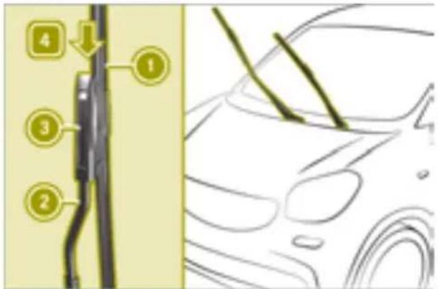
text_image
Diagram showing car engine components with numbered labels pointing to parts of the main body and side panel▶ Slide new window wiper blade ① in the direction of arrow ④ onto mounting ③ of if wiper arm ②.
! Never open the service cover or tailgate in a wiper arm has been folded away from th
windshield or rear window. Never fold a wiper arm without a wiper blade back onto
the windshield or rear window. Hold the windshield wiper arm firmly when you change the wiper blade. If you release the wiper arm without a wiper blade and it falls onto the window, the window may be damaged by the force of the impact.
The window wiper blade snaps into place.
▶ Check that the window wiper blade is positioned correctly.
▶ Carefully fold wiper arm ② onto the wind-shield.
Changing the rear window wiper blade (smart fortwo coupe)
Changing the window wiper blades on the windshield
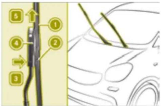
text_image
5 ① ④ ② 3▶ Fold the wiper arm away from the wind-shield.
▶ Press release clips ② on mounting ④ in the direction of windshield ③. The catch tab is released from the mounting and the
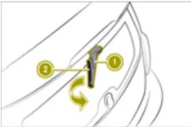
text_image
Diagram showing a device with labeled components and directional arrows, likely illustrating a mechanical or electrical system.▶ Remove SmartKey from ignition lock.
▶ Fold wiper arm ① away from the rear window until you hear it engage.
▶ Unscrew window wiper blade ② in the direction of the arrow until it is released from the retainer on the wiper arm.
▶ Pull out window wiper blade ②.
▶ Press new window wiper blade ② onto wiper arm ① until it engages.
▶ Check that window wiper blade ② is positioned correctly.
▶ Fold wiper arm ① back onto the rear window.
▶ Prepare the vehicle for cleaning.
▶ Remove excess dirt.
Drive through the automatic car wash.
▶ Remove wax from the front windshield and
the wiper blades.
Cleaning the vehicle
Useful information
Regular care maintains the appearance and quality of the vehicle over time.
Observe the following when cleaning and caring for the vehicle:
▶ Do not clean the engine.
▶ Do not clean the vehicle whilst charging.
▶ Use soft, moist cloths.
▶ Use care products and cleaning agents recommended and approved by smart.
▶ Do not use acidic cleaning agents.
▶ In winter, carefully remove road salt as soon as possible.
Cleaning the vehicle exterior
Cleaning the vehicle
Preparing the vehicle for cleaning

WARNING
Braking efficiency is reduced after washing the vehicle. There is a risk of an accident.
After the vehicle has been washed, brake carefully while paying attention to the traffic conditions until full braking power is restored.
▶ Close the side windows completely.
▶ Switch off the climate control blower.
▶ Turn the windshield wiper to position 0.
Cleaning in an automatic car wash
! Never clean your vehicle in a Touchless Automatic Car Wash as these use special cleaning agents. These cleaning agents can damage the paintwork or plastic parts.
If the windshield wipers leave smears after the vehicle has passed through the car wash, this may be caused by wax or other residue. This residue can be removed with washer fluid.
Washing by hand
▶ Locate a washing bay equipped for hand-washing.
▶ Prepare the vehicle for cleaning.
▶ Apply mild cleaning agent with a soft vehicle sponge.
▶ Thoroughly hose the vehicle with a gentl jet of water; do not point the water jet directly towards the air inlet grille.
▶ Dry the vehicle off with a chamois.
Cleaning with a power washer

WARNING
The water jet from a circular jet nozzle (d blasters) can cause invisible exterior damage to the tires or chassis components.
Components damaged in this way may fa unexpectedly. There is a risk of an accident.
Do not use power washers with circular jet nozzles to clean the vehicle. Have damaged tires or chassis components replaced immediately.
! Always maintain a distance of at least 11.8 in (30 cm) between the vehicle and the power washer nozzle. Information about the correct distance is available from the equipment manufacturer.
Move the power washer nozzle around when cleaning your vehicle.
Do not aim directly at any of the following:
- Tires
- Door gaps, roof gaps, joints, etc.
• Electrical components - Battery
-
Connectors
-
Lamps
- Seals
- Trim
- Ventilation slots
Damaged seals or electrical components can lead to leaks or failures.
▶ Prepare the vehicle for cleaning.
▶ Maintain a distance of at least 11.8 in (30 cm) between the power washer nozzle and the vehicle.
▶ Keep moving the nozzle whilst cleaning.
Cleaning the sensors
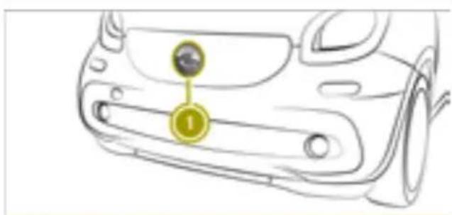
text_image
Diagram of a car's front panel with labeled component '1' and circular marker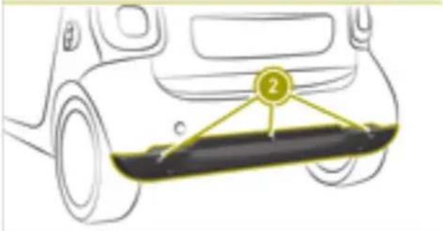
text_image
Diagram of a car's rear bumper with numbered label pointing to the bumper area① Forward collision warning sensor
② Parking aid sensors
▶ Clean sensors with water, car shampoo and a soft cloth.
Cleaning the wheels

WARNING
The water jet from a circular jet nozzle (di blasters) can cause invisible exterior damage to the tires or chassis components.
Components damaged in this way may fail unexpectedly. There is a risk of an accident.
Do not use power washers with circular jet nozzles to clean the vehicle. Have damaged tires or chassis components replaced immediately.
! Do not use acidic wheel cleaning products to remove brake dust. This could damage wheel bolts and brake components.
! Do not park your vehicle for a long period of time directly after cleaning, particularly after cleaning the wheel rim with wheel cleaner. Wheel cleaner can lead to the increased corrosion of the brake discs and pads. Therefore, drive for a few minutes after cleaning. By heating up the brakes, the brake discs and pads dry. The vehicle can then be parked for a long period of time.
▶ Clean the wheels with an acid-free cleaning agent.
Cleaning the windows and windshield wiper
Cleaning the windows

WARNING
You could become trapped by the wind-shield wipers if they start moving while cleaning the windshield or wiper blades. There is a risk of injury.
Always switch off the windshield wipers and the ignition before cleaning the windshield or wiper blades.
▶ Place the wiper arms in the vertical position and fold them away from the window.
▶ Clean the inside and outside of the windows with a damp cloth and a cleaning agent recommended by smart.
▶ Clear deposits regularly from the wind-shield and rear window to ensure that water can drain unhindered.
Cleaning the window wiper blades
Place the wiper arms in the vertical position and fold them away from the window.
▶ Clean the window wiper blades with a soft cloth.
▶ Fold the wiper arms back into place.
Cleaning the panoramic roof (smart fortwo coupe)
! Only use cleaning agents or cleaning cloths which are suitable for plastic light
lenses. Unsuitable cleaning agents or cleaning cloths could scratch or damage the plastic windows of the panoramic roof. Do not use cleaning agents which contain solvents.
▶ Apply mild cleaning agent for plastic lenses and wipe off with a moist sponge.
Cleaning the roof
Dry cleaning
▶ Brush from the front to the back using a soft brush.
Wet cleaning
▶ Dry clean first.
▶ Wash down with a soft brush or sponge lukewarm water.
▶ Rinse with clean water.
Cleaning the soft top (smart fortwo cabrio)
Useful information
! Never use a power washer to clean the soft top, otherwise water could enter the vehicle interior.
! Only clean the folding top and rear soft top when they are closed.
Dry cleaning
▶ Brush from the front to the back using a soft brush.
Wet cleaning
▶ Dry clean first.
▶ Wash down with a soft brush or sponge and lukewarm water.
▶ Rinse with clean water.
Cleaning the exterior lighting
▶ Apply mild cleaning agent for plastic lenses and wipe off with a wet sponge.
Cleaning and caring for paintwork
! Do not attach stickers to the paint surface. The adhesive residues may damage the paintwork.
- Remove impurities immediately by rubbing carefully.
- Soak insect remains with insect remover and rinse off.
- Soak bird droppings with water and rinse off.
▶ Use tar remover to remove tar stains.
▶ Use silicone remover to remove wax.
▶ Remove coolant, brake fluid, tree resin, oils, fuels and greases by rubbing carefully with a cloth soaked in petroleum ether or lighter fluid.
▶ Use a suitable touch-up stick, e.g. MB Touch-Up Stick, to repair slight damage to the paintwork quickly and provisionally.
When water no longer forms beads on the paint surface, use the care product Paint Care, which has been approved by smart.
This is the case approximately every three five months, depending on the climate conditions and the care product used.
If any dirt has penetrated the paint surface or the paint has become dull, the paintwork should be cleaned. Use the care product Pa Care recommended and approved by smart clean the paintwork.
Do not use these care products in the sun on the hood while the hood is hot.
Cleaning the vehicle interior
Cleaning the displays
! For cleaning, do not use any of the following:
• alcohol-based thinner or gasoline
• abrasive cleaning agents
• commercially-available household cleaning agents
These may damage the display surface. Do not put pressure on the display surface when cleaning. This could lead to irreparable damage to the display.
▶ Switch off the display and let it cool down.
▶ Clean the display surface with a microfiber cloth and cleaner for TFT/LC displays.
- Dry the display surface using a dry micro-fiber cloth.
Cleaning the steering wheel and the gear lever
▶ Wipe off with a moist cloth, or use a leaf care agent recommended by smart.
Cleaning the seat belts

WARNING
Seat belts can become severely weakened if bleached or dyed. This could cause the seat belts to tear or fail, for instance, in event of an accident. This poses an increased risk of injury or fatal injury. Never bleach or dye the seat belts.
! Do not clean the seat belts using chemical cleaning agents. Do not dry the seat belts by heating at temperatures above 176 °F (80 °C) or in direct sunlight.
▶ Clean the seat belts using only lukewarm soapy water.
Cleaning and caring for seats
Please note
! Do not use microfiber cloths to clean genuine leather or artificial leather covers, as these are too aggressive and, if used often, may damage the cover.
Regular care maintains the appearance and feel of the seats over time.
Cleaning and caring for genuine leather seat covers
▶ Wet a cloth with water and clean the seat covers. Do not allow the leather to become soaked.
▶ Wipe off with a dry cloth.
▶ Apply a leather care agent recommended by smart.
Cleaning synthetic leather seat covers
▶ Wet a cloth with detergent water and clean the seat covers.
Cleaning cloth seat covers
▶ Wet a microfiber cloth with detergent water.
▶ Rub cloth covers with care, cleaning entire sections of the cover.
▶ Allow the seat to dry.
Cleaning DINAMICA seat covers
▶ Wet a cloth with water.
▶ Clean entire sections of the cover.
Cleaning the paneling
Cleaning the plastic trim

WARNING
Care products and cleaning agents containing solvents cause surfaces in the cockpit to become porous. As a result, plastic parts may come loose in the event of air bag deployment. There is a risk of injury. Do not use any care products and cleaning agents to clean the cockpit.
! Never attach the following to plastic surfaces:
- stickers
- films
• perfume oil container or similar You could otherwise damage the plastic.
To maintain the appearance of high-quality plastic surfaces, do not allow surfaces to come into contact with cosmetics, insect repellents or sun creams.
Clean the plastic trim with a damp cloth.
▶ Use care products and cleaning agents recommended by smart to remove heavy soiling.
Cleaning the headliner (smart fortwo coupe)
▶ Remove heavy soiling using a soft brush or
an a cleaning agent recommended by smart.
Cleaning the carpets
▶ Use carpet and textile cleaning agents recommended by smart.
Cleaning the trim elements
! Do not use solvent-based cleaning agents such as tar remover, wheel cleaners, polishes or waxes. There is otherwise a risk of damaging the surface.
▶ Clean the trim elements with a moist microfiber cloth.
▶ Use care products and cleaning agents recommended by smart to remove heavy soiling.
Observing service due dates
The ⚡ and ⚡ indicator lamps in the instrument cluster display are reminders of upcoming service due dates:
• : minor service.
• 无: major service.
The service interval is based on normal operation of the vehicle. Observe the following if the vehicle is operated under arduous conditions or increased loads, e.g. regular city driving with frequent intermediate stops:
▶ Carry out service work more often than specified by the service interval.
▶ Check the tires more frequently.
Current information on the type of service can be obtained at a smart Center or a qualified specialist workshop.
Parking the vehicle for a long period
! Please note that if the vehicle is not used for prolonged periods, vehicle damage may occur and the battery may discharge or become damaged.
▶ Visit a qualified specialist workshop and seek advice.
Securing the vehicle in the event of an accident or a breakdown
Securing the vehicle
! When a tire is damaged, the danger area must be kept clear of all persons.
▶ Stop the vehicle away from traffic on solid, non-slippery ground.
▶ Switch on the hazard warning lights.
▶ Turn the front wheels to the straight-ahead position.
▶ Switch off the engine.
▶ Passengers should leave the vehicle.
▶ Secure the vehicle against rolling away.
In the case of a flat tire, without TIREFIT the vehicle cannot be made roadworthy again using the on-board equipment. No emergency call can be made via the smart Audio System. The vehicle owner and the driver of the vehicle are responsible for equipping the vehicle with an appropriate breakdown kit and seeking assistance in the event of a breakdown.
Switching the hazard warning lamps on and off
When the hazard warning lamps are switched on, all the turn signal lamps flash.
The hazard warning lamps automatically switch on in the following cases:
- an air bag is deployed.
- the vehicle decelerates rapidly from a speed of more than 45 mph (70 km/h) and comes to a standstill.
The hazard warning lamps switch off automatically if the vehicle reaches a speed of above 6 mph (10 km/h) again after a full brake application.
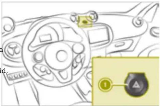
text_image
a d,▶ To switch on the hazard warning lamps manually: press button ①.
the Securing the vehicle to prevent it from rolling away
Securing on level ground
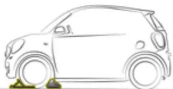
natural_image
Side profile line drawing of a compact car (no text or symbols)▶ To change the wheel, place chocks or other suitable items under the front and rear of the wheel that is diagonally opposite the wheel you wish to change.
Securing on a downhill gradient
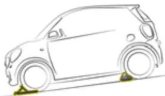
natural_image
Side profile line drawing of a compact car with wheels and roof (no text or symbols)▶ Place wheel chocks or other suitable items There is a risk of an accident.
in front of the wheels of the front and rear axle.
Do not drive the vehicle. Contact a qualified specialist workshop.
Removing the vehicle tool tray
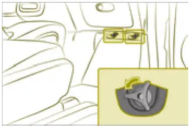
natural_image
Interior view of a car with seats and window controls, showing a small inset image of a helmet (no text or symbols)The towing eye and the TREFIT kit are located in the vehicle tool tray under the glove box.
- Remove bolts in the front-passenger foot-well.
▶ Remove the vehicle tool tray.
Sealing tires using the TREFIT kit
Useful information
The tire sealant is pumped into the tire. TIREFIT is a tire sealant. TIREFIT is used to seal punctures of up to 0.16 in (4 mm), particularly those in the tire tread, at outside temperatures of up to -4 °F (-20 °C).
Please note

WARNING
In the following situations, the tire sealant is unable to provide sufficient breakdown assistance, as it is unable to seal the tire properly:
- there are cuts or punctures in the tire larger than those mentioned above.
• the wheel rim is damaged. - you have driven at very low tire pressures or on a flat tire.

WARNING
The tire sealant is harmful and causes irritation. It must not come into contact with your skin, eyes or clothing or be swallowed. Do not inhale TREFIT fumes. Keep tire sealant away from children. There is a risk of injury.
If you come into contact with the tire sea ant, observe the following:
- Rinse off the tire sealant from your skin immediately with water.
- If the tire sealant comes into contact with your eyes, immediately rinse them thoroughly with clean water.
- If tire sealant is swallowed, immediately rinse your mouth out thoroughly and drink plenty of water. Do not induce vomiting, and seek medical attention immediately.
- Immediately change out of clothing which has come into contact with tire sealant.
- If an allergic reaction occurs, seek medical attention immediately.

WARNING
A tire temporarily sealed with tire sealant impairs the driving characteristics and is not suitable for higher speeds. There is a risk of accident.
You should therefore adapt your driving style accordingly and drive carefully. Do not exceed the specified maximum speed with a tire that has been repaired using tire sealant.
The maximum permissible speed for a tire sealed with tire sealant is 50 mph (80 km/h).
! After use, excess tire sealant may run out of the filler hose. This could cause stains. Therefore, place the filler hose in the plastic bag that contained the TREFIT kit.

Environmental note
Have the used tire sealant bottle disposed of professionally, e.g. at a qualified specialist workshop.
Comply with the manufacturer's safety instructions on the sticker on the tire inflation compressor.
Filling with tire sealant
Leave foreign bodies which have penetrated the tire in the tire.
▶ Remove the vehicle tool tray.
▶ Remove the TREFIT Kit, consisting of a sealant bottle and a tire inflation compressor, from the vehicle tool kit.
▶ Affix the 50 mph (80 km/h) maximum sp sticker to the instrument cluster within the driver's field of vision.
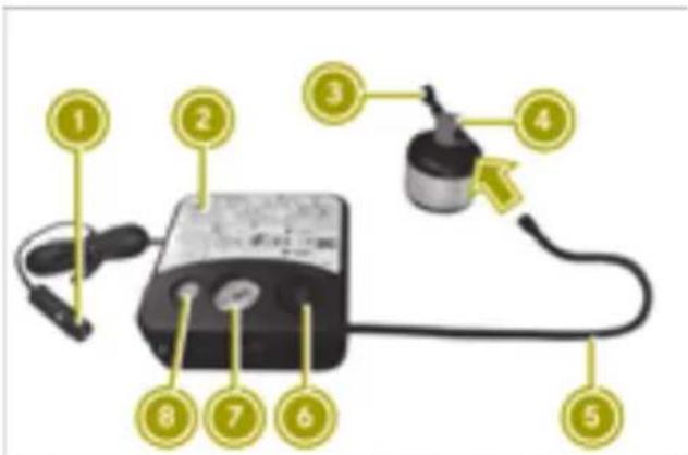
text_image
Diagram of a handheld device with numbered parts labeled 1 through 8, showing connections to a power supply or meter.▶ Unwind plug ① with the cable from tire inflation compressor ②.
▶ Remove hose ⑤ from the bottom section tire inflation compressor ②.
▶ Unscrew the cap from tire sealant bottle ④.
▶ Connect hose ⑤.
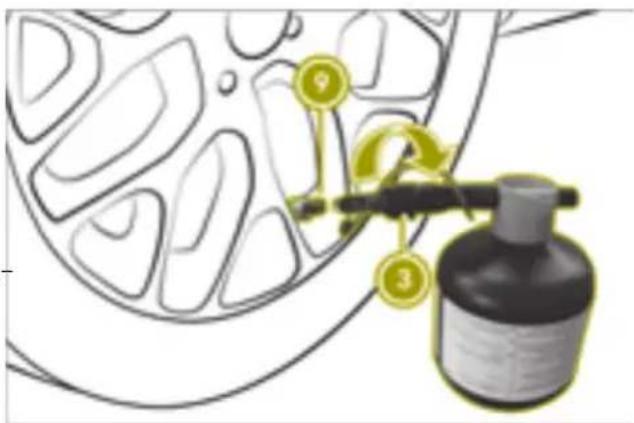
text_image
Diagram showing a car wheel with numbered annotations pointing to a bottle and a hose, likely illustrating a mechanical or safety concept.▶ Remove valve flap from valve ⑨ on the defective tire.
▶ Unscrew cap from filler hose ③.
Screw filler hose ③ onto valve ⑨.
▶ Insert connector ① into the 12 V socket.
▶ Turn the SmartKey to position 1 in the ed ignition lock.
▶ Press on/off switch ⑥ on tire inflation compressor ② to position 1. The tire sealant is pumped into the tire. The pressure in pressure gauge ⑦ may briefly rise to approximately 600 kPa (6.0 bar/86 psi).
i Preventing damage to the tire inflation compressor Do not switch off the tire inflation compressor during this phase.
▶ Let the tire inflation compressor run for a maximum of 15 minutes, then allow it to cool down.
The tire pressure in pressure gauge ⑦ must be at least 180 kPa (1.8 bar/26 psi).
Allow any leaked tire sealant to dry. It can then be removed like a layer of film.
Have any clothing stained with tire sealant cleaned as soon as possible with perchloro-ethylene.
Further procedure if the pressure of the sealed tire is below 180 kPa

WARNING
If the specified tire pressure is not reached, the tire is too severely damaged. The tire sealant cannot offer assistance with a flat tire in this case. Damaged tires as well as tire pressure that is too low can
impair the braking and driving characteristics. There is a risk of an accident.
Do not drive any further. Notify a qualified specialist workshop.
▶ Drive to the nearest qualified specialist workshop and have the tire changed there.
Have the tire sealant bottle and filler hose replaced as soon as possible at a qualified specialist workshop.
▶ Switch off the tire inflation compressor.
▶ Unscrew the filler hose from the valve of the defective tire.
Please note that tire sealant may escape when unscrewing.
▶ Slowly move the vehicle approximately 30 ft (10 m) forward or back.
▶ Pump up the tire again.
After a maximum of 15 minutes, the tire R pressure must be at least 180 kPa (1.8 bar/26 psi).
Adjusting the tire pressure
Increasing the tire pressure
▶ Switch on the tire inflation compressor.
▶ Observe the display.
Reducing the tire pressure
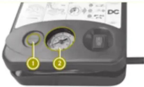
text_image
DC 1 2Further procedure if the pressure of the sealed tire is at least 180 kPa
▶ Switch off the tire inflation compressor.
▶ Unscrew the hose from the valve of the defective tire.
Please note that tire sealant may escape when unscrewing.
▶ Stow the tire sealant bottle and the tire inflation compressor.
▶ Perform a test drive.
The maximum permissible speed for a tire sealed with tire sealant is 50 mph (80 km/h).
▶ Stop driving after approximately 2 miles (3 km) and check the tire pressure with the tire inflation compressor.
The tire pressure must now be at least 130 kPa (1.3 bar/19 psi). The precise values are located on the door pillar (B-pillar) only the driver's side.
▶ If necessary, adjust the tire pressure.
▶ Unscrew the filler hose from the valve on the sealed tire.
Please note that tire sealant may escape when unscrewing.
▶ Screw the valve cap onto the valve of the sealed tire.
▶ Pull the tire sealant bottle out of the tire inflation compressor. The filler hose stays on the tire sealant bottle.
▶ Press button ① next to pressure gauge
Even unused tire sealant loses its effect, tiveness over time.
Have the tire sealant bottle replaced ever four years at a qualified specialist workshop.
Towing the vehicle
Please note
WARNING
Functions relevant to safety are restricted or no longer available if:
• the ignition is switched off
- the brake system or the power steering is malfunctioning
- there is a malfunction in the power supply or the vehicle's electrical system
If your vehicle is being towed, much more force may be necessary to steer or brake. There is a risk of an accident.
In such cases, use a tow bar. Before towing, make sure that the steering moves freely.

WARNING
You can no longer steer the vehicle if the steering wheel lock has been engaged. There is a risk of an accident.
Always switch off the ignition when towing the vehicle with a tow cable or a tow bar.

WARNING
When towing or tow-starting another vehicle and its weight is greater than the permissible gross weight of your vehicle, the:
- the towing eye could detach itself
- the vehicle/trailer combination could rollover.
There is a risk of an accident.
When towing or tow-starting another vehicle, its weight should not be greater than the permissible gross weight of your vehicle.
Information on the vehicle's permissible gross mass can be found on the vehicle identification plate ( page 185).
! Observe the following points when towing with a tow rope:
- Secure the tow rope on the same side on both vehicles.
- Ensure that the tow cable is not longer than legally permitted. Mark the tow cable in the middle, e.g. with a white cloth (30 x 30 cm). This will make other road users aware that the vehicle is being towed.
- Only secure the tow cable to the towing eye.
- Observe the brake lamps of the towing vehicle while driving. Always maintain
a distance so that the tow rope does not sag.
- Do not use steel cables or chains to tow your vehicle. You could otherwise damage the vehicle.
! Do not use the towing eyes for recovery purposes as this could damage the vehicle. If in doubt, recover the vehicle with a crane.
! When towing, pull away slowly and smoothly. If the tractive power is too high, the vehicles could be damaged.
! Do not tow with sling-type equipment. This could damage the vehicle.
! The vehicle can be towed a maximum of 30 miles (50km). The towing speed of 30 mph (50 km/h) must not be exceeded. If the vehicle has to be towed more than 30 miles (50km), the entire vehicle must be raised and transported.
Observe the legal requirements for the relevant countries when towing.
Always have the vehicle transported in the following cases:
- The warning lamp lights up and DoDo Not Tow Vehicle with Wheels on Ground appears in the display of the instrument cluster.
- The multifunction display is not working.
- One of more of the following warning lamps is lit up:
- drive diagnostics (red)
- 12 V battery
- The brake pedal begins to pulsate as the towing procedure commences.
The vehicle must be moved over a long distance.
The transmission must be in position N when the vehicle is being towed.
Before the vehicle is towed, switch off the automatic locking feature. The driver could otherwise be locked out when pushing or towing the vehicle.
i Vehicles with the basic carrier installed:
Do not tow the vehicle with the basic carrier installed.
Do not secure the tow rope or tow bar to the basic carrier.
Observe the notes on the selector lever whe towing the vehicle.
Installing the towing eye
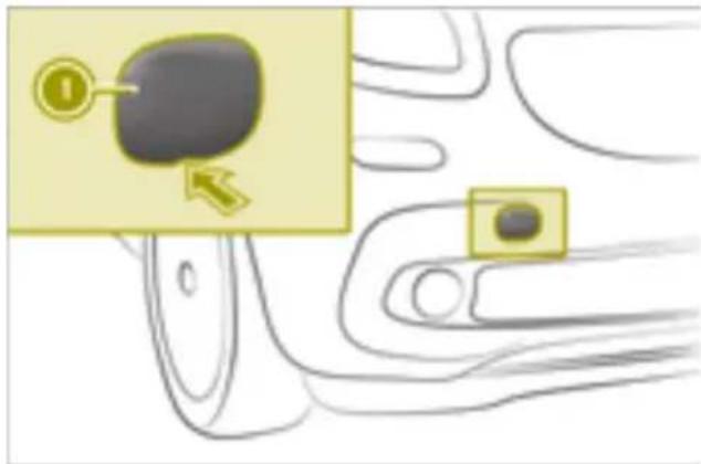
text_image
Diagram showing a device with a highlighted button labeled '1' and an arrow pointing to it, alongside a close-up of the button.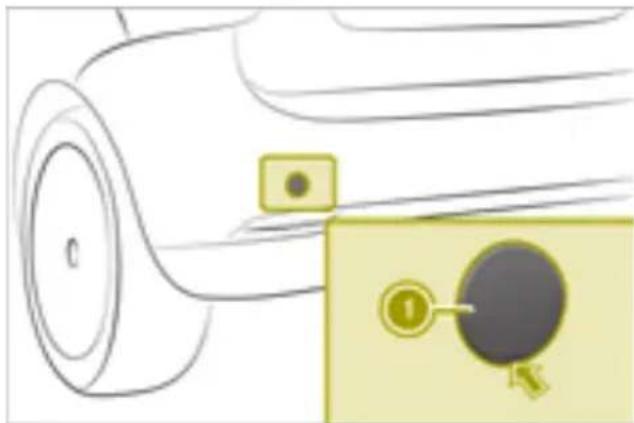
natural_image
Diagram of a car wheel with a highlighted keyhole and a small inset showing a circular component (no text or symbols)Transporting the vehicle
! Only secure the vehicle by the wheels or rims, not by parts of the vehicle such as the axle or steering components. Otherwise the vehicle could be damaged.
▶ Turn the SmartKey to position 2 in the ignition lock. Shift the transmission to position N.
As soon as the vehicle has been loaded:
▶ Apply the parking brake.
▶ Shift the transmission to position P.
▶ Remove the SmartKey.
▶ Lash down the vehicle.
Removing the towing eye
▶ Loosen the towing eye and unscrew it.
▶ Attach the cover to the recess at the top and engage it at the bottom.
▶ Stow the towing eye in the vehicle tool tray.
Manually releasing the selector lever lock
The towing eye can be attached to the front or rear of the vehicle.
▶ Remove the towing eye from the vehicle tool tray.
▶ Carefully lever off cover ① on the vehiclequently be re-applied.
▶ Screw in the towing eye to the stop.
equently be re-applied.
The selector lever lock can be manually released in the event of an electrical malfunction, e.g. if the parking lock has been deactivated for towing and should subse-
! Do not use any sharp-edged objects to pry out the cover from the center console. Otherwise, the cover or the center console could be damaged.
Towing a vehicle with both axles on the ground
▶ Turn the SmartKey to position 2 in the ignition lock.
▶ Depress the brake pedal and keep it depressed.
▶ Shift the automatic transmission to position N.
The selector lever lock can be manually released in the event of an electrical fault.
▶ Release the brake pedal.
▶ Release the parking brake.
▶ Switch on the hazard warning lights.
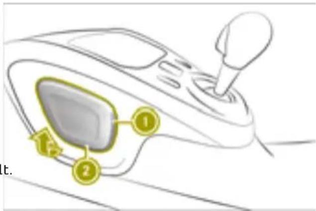
text_image
Diagram of a device's internal components with numbered labels pointing to key parts▶ Apply the parking brake.
▶ Open the drawer on the front-passenger side.
▶ Lever off cover ① on the center console from bottom edge ② using a flat, blunt object.
▶ Pull cover ① in the direction of the arrow. types.
- do not allow bulbs to come into contact with moisture.
• have LEDs changed at qualified specialist workshops only.
Change only the bulbs described below yourself in accordance with the specified bulb types.
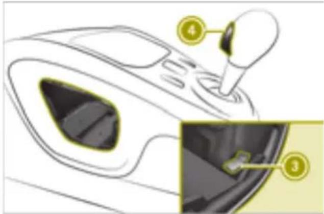
text_image
Diagram of a car gear shift lever with labeled parts 3 and 4, showing internal components and motion path.▶ Pull yellow release ③ behind the trim up and simultaneously press release button ④ on the selector lever.
▶ Shift the selector lever to N or P.
Replacing front bulbs
Replacing low-beam headlamps and high-beam headlamps
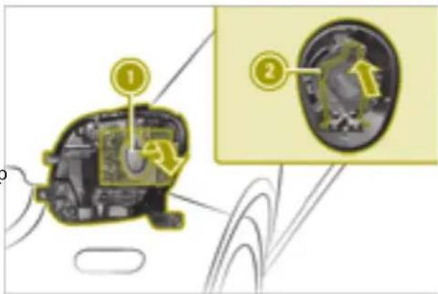
text_image
Diagram of a mechanical device with labeled parts and an inset showing internal components, likely illustrating a gear or mechanism.Replacing the bulbs
Useful information

WARNING
Bulbs, lamps and connectors can get very hot when operating. If you change a bulb, you could burn yourself on these components. There is a risk of injury.
Allow these components to cool down before changing a bulb.
▶ Switch off lights.
▶ Open the service cover.
▶ Remove cover ①.
▶ Pull out the connector.
▶ Press retainer ② inwards and to the left.
▶ Pull the bulb out.
▶ Insert the new bulb.
▶ Lock retainer ②.
▶ Insert the connector.
▶ Replace and engage cap ①.
Observe the following rules when changing bulbs:
- only replace bulbs when the engine is switched off.
- do not use bulbs that have been dropped or show signs of visible damage, e.g. scratches.
- do not touch the glass bulb with your bare hands.
- only use bulbs in enclosed lamps designed for that purpose.
- only install spare bulbs of the same type and with a specified voltage.
Replacing the front turn signal lamps
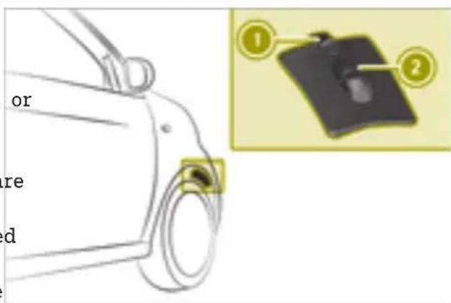
text_image
or re d▶ Switch off lights.
▶ Turn the respective front wheel inward.
▶ Push clamp ① down.
▶ Remove cover ② up.
▶ Turn the bulb holder counter-clockwise and remove it.
▶ Remove the bulb from the bulb holder.
▶ Insert the new bulb.
▶ Insert the bulb holder and turn it clockwise until it engages.
▶ Insert and engage cover ②.
Replacing the side turn signal lamps
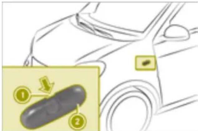
text_image
Diagram showing a car's side panel with numbered instructions and a close-up of the component being inserted.▶ Carefully insert a flat tool into recess ①.
▶ Lever off side turn signal ②.
▶ Unscrew the bulb from the bulb holder.
▶ Insert the new bulb into the bulb holder.
▶ Re-install side turn signal ②.
Replacing rear bulbs
Changing the tail lamp bulbs
Tail lamps without partial LEDs
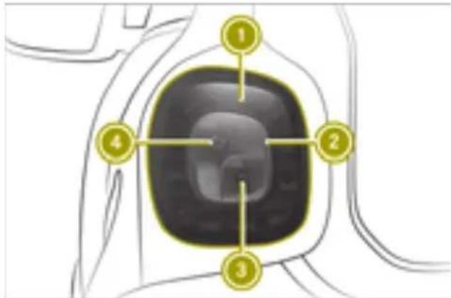
text_image
Diagram of a device with numbered components, highlighting a central screen area and surrounding wiring.① Rear lamp, brake lamp and side marker lamp
② Rear fog lamp
③ Backup lamp
④ Turn signals
Tail lamps with partial LEDs
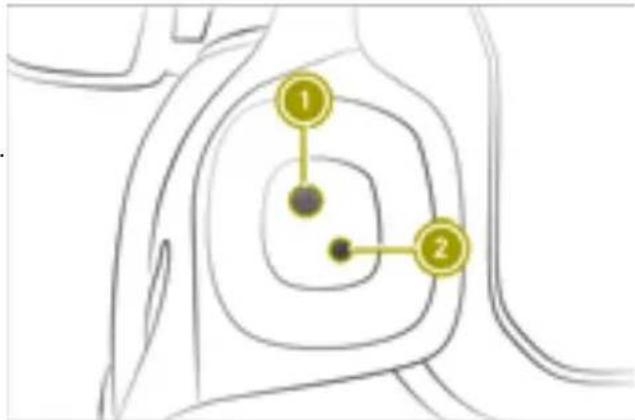
flowchart
graph TD
    A["1"] --> B["2"]
    B --> C["3"]
① Turn signals
② Backup lamp
Removing the tail lamp cover
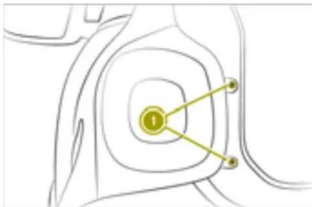
natural_image
Diagram of concentric circular layers with a central yellow circle and two connected points, no text or symbols present.▶ Switch off lights.
▶ smart fortwo coupe: open the upper and lower tailgate.
▶ smart fortwo cabrio: open the lower tail-gate.
▶ smart fortwo cabrio: fold the rear soft top up.
▶ Loosen screws ①.
▶ Remove the tail lamp.
▶ Carefully insert a flat tool under the plastic hanger on the tail lamp.
▶ Lift the connector and remove it.
Replacing a defective tail lamp bulb
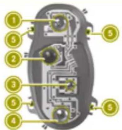
text_image
Labeled diagram of a biological cell with numbered components for identification① Rear lamp, brake lamp and side marker lamp (vehicles without partial LEDs)
② Turn signals
③ Backup lamp
④ Rear fog lamp (vehicles without partial LEDs)
▶ Release four tabs ⑤ on the bulb holder.
▶ Remove the bulb holder.
▶ Pull the defective bulb out.
▶ Insert the new bulb.
▶ Re-install the bulb holder.
▶ Insert the connector.
▶ Insert the tail lamp until you hear it engage.
▶ Tighten the screws on the tail lamp.
Replacing the license plate lamp
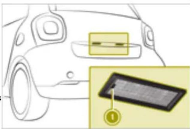
text_image
Diagram showing car front and interior with a magnified inset highlighting a component labeled '①'▶ Insert a flat tool into recess ①.
▶ Remove the cover from the license plate lamp.
▶ Remove the bulb from the holder.
▶ Insert the new bulb into the holder.
▶ Insert the lamp lens into the license plate lamp.
Replacing the interior lighting
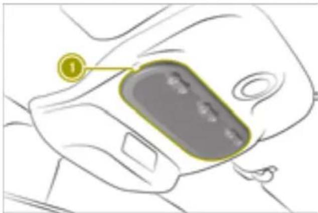
text_image
Diagram of a car interior showing a highlighted device with numbered label '1' pointing to the interior area.▶ Insert a flat tool into the recess.
▶ Lever off lamp lens ①.
▶ Remove the bulb from the holder.
▶ Insert the new bulb into the holder.
▶ Re-install the lamp lens.
Changing fuses
Please note

WARNING
If you manipulate or bridge a faulty fuse or if you replace it with a fuse with a higher
amperage, the electric cables could be overloaded. This could result in a fire. There is a risk of an accident and injury. Always replace faulty fuses with the specified new fuses having the correct amperage.
! Only use fuses that have been approved for smart vehicles and which have the correct fuse rating for the system concerned. Otherwise, components or systems could be damaged.
! Make sure that no moisture can enter the fuse box when the cover is open.
The electrical fuses disconnect defective circuits. If a fuse blows, all the connected components and their functions will fail.
Blown fuses must be replaced with fuses of the same rating, which you can recognize by the color and value. The fuse ratings are listed in the fuse allocation chart page 188).
If new fuses blow, the cause for this must diagnosed and rectified at a qualified specialist workshop.
Certain vehicle functions are protected via the fuse box in the front area. Access to the fuses is very restricted. Have a blown fuse the front area replaced at a qualified specialist workshop.
Preparing the vehicle to change a fuse
▶ Apply the parking brake.
▶ Switch off all electrical consumers.
▶ Turn the SmartKey to position 0 in the ignition lock and remove it.
▶ Check whether all indicator lamps in the instrument cluster are off.
Changing a fuse (left-hand drive vehicle)
! Do not use a pointed object such as a screwdriver to open the cover in the dashboard. You could damage the dashboard of the cover.
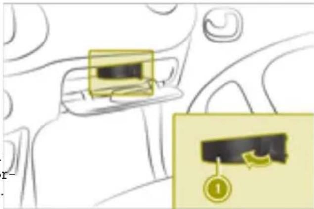
natural_image
Diagram of a car interior showing a highlighted seatbelt and a zoomed-in view of the seatbelt (no text or symbols present)▶ Open the front-passenger door.
▶ Open the glove box.
▶ To open: open cover ① in the direction the arrow.
Replace the defective fuse.
▶ To close: insert and fold in cover ① until it engages.
▶ Close the glove box.
be Replacing the SmartKey battery
WARNING
^e Batteries contain toxic and corrosive sub- instances. If batteries are swallowed, it can result in severe health problems. There is risk of fatal injury.
Keep batteries out of the reach of children. If a battery is swallowed, seek medical attention immediately.
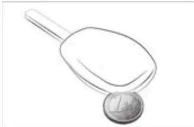
natural_image
Simple line drawing of a spoon and coin (no text or symbols)▶ Insert a flat tool, e.g. a coin, into the recess.
▶ Turn the tool until the cover of the battery tray opens.
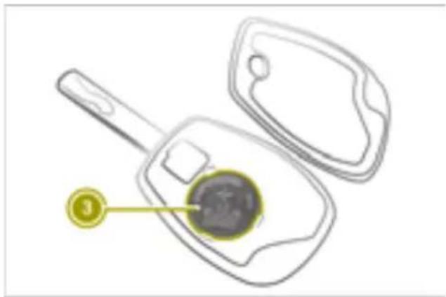
natural_image
Line drawing of a keychain with a circular component inserted into it, no text or symbols presentThe SmartKey batteries contain perchlorate material, which may require special handling and regard for the environment. National guidelines must be observed during disposal. In California, www.dtsc.ca.gov/HazardousWaste/Perchlorate/index.cfm.
Opening a door with the emergency release
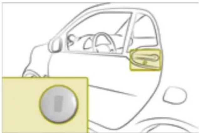
natural_image
Side view of a car with dashboard and steering wheel (no text or symbols visible)If the vehicle cannot be opened using the remote control key, the vehicle can be open using the emergency release.
If the driver's door is unlocked and opened with the SmartKey in the emergency release, the anti-theft alarm system will issue an alarm. To disable the alarm, switch on the ignition.
▶ Carefully remove the cover from the emergency release.
▶ Insert the SmartKey into the emergency release on the driver's door.
▶ Turn the SmartKey counter-clockwise.
▶ Remove the SmartKey from the lock.
▶ Push the cover into the emergency release until it engages.
▶ Open the door.
▶ To disable the alarm from the anti-theft alarm system: switch on the ignition.
Locking the doors in an emergency
Locking the doors with the locking button
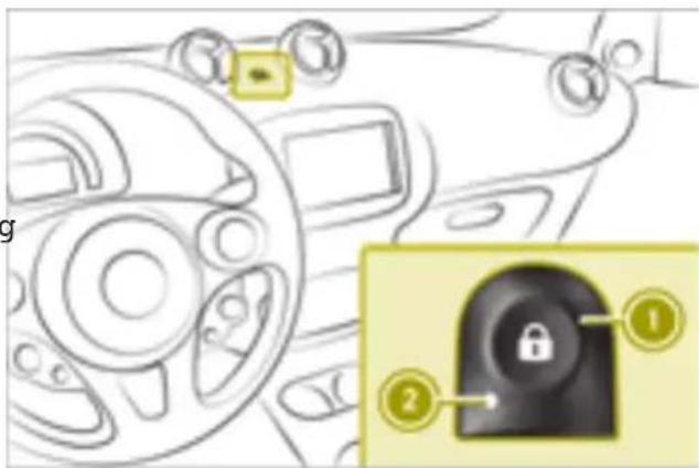
text_image
Diagram of a car interior with labeled parts and a lock icon highlighting the door key▶ Remove the SmartKey from the ignition lock.
▶ Open the driver's door.
▶ Close the other doors and the tailgate.
▶ Press and hold button ①. An audible locking and unlocking sound can be heard. Wait until the third (locking) sound, before releasing button ①.
Leave the vehicle and close the driver's door.
The doors, tailgate and socket cap are locked. The anti-theft alarm system is armed.
▶ From the outside, check that the doors, ed tailgate and socket cap are locked.
Locking the doors with the emergency locking
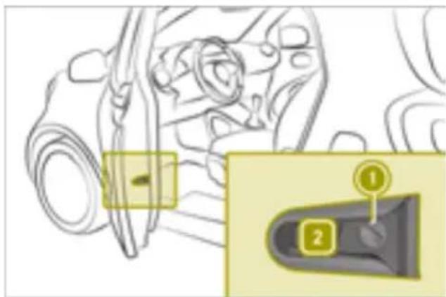
text_image
Technical diagram showing a mechanical component with labeled parts and an inset view of a control panel.▶ Insert the SmartKey into slot ① on the left door.
▶ Turn the SmartKey towards the hood as far as it will go to position 2.
▶ Close the left door.
▶ Repeat the procedure described above on the right door.
▶ Check that the doors are locked.
If you lock the vehicle using the emergency locking, the tailgate and fuel filler flap are not locked. The anti-theft alarm system is not armed.
Notes on display messages
The display shows warnings, malfunctions or additional information. A warning tone also sounds with some display messages.
Messages from all categories can contain important information that must be observed. Have malfunction messages checked at an authorized Mercedes-Benz Center as soon as possible. If an error message is not followed up with a repair, this lead to damage that is not covered by the Mercedes-Benz Limited Warranty including injuries or material damage.
Display messages with graphic symbols may be simplified in the Operator's Manual and may differ from the symbols shown in the display.
Low-priority display messages can be hidden by pressing OK on the steering wheel. High-priority messages are shown in red.
The display messages are then stored in the message memory and can be called up for as long as the ignition remains switched on.
Switching off the ignition clears the message can memory.
Locking and unlocking
| Problem | Possible causes/consequences and ▶ Solutions |
| SmartKey will not lock or unlock the vehicle. | A strong source of radio waves is interfering with the signal. ▶ Stand closer to the door lock and try to lock/unlock the vehicle again. |
| SmartKey battery is low or discharged. ▶ Unlock the vehicle with the SmartKey in the emergency release or lock the vehicle with emergency locking. ▶ Replace the SmartKey battery. | |
| SmartKey is malfunctioning. To lock: ▶ Press the locking button and close the door within five seconds. The vehicle still will not lock. ▶ Lock driver's door using emergency locking. ▶ Consult a qualified specialist workshop. To unlock: ▶ Unlock vehicle with the SmartKey in the emergency release. ▶ Consult a qualified specialist workshop. | |
| SmartKey is lost. | Have the SmartKey deactivated or replaced at a qualified specialist workshop. ▶ Report loss of the SmartKey to vehicle insurer. |
| Remove Key appears. Warning tone sounds. | The SmartKey is in the ignition lock. ▶ Remove the SmartKey. |
| Warning tone sounds. | Driver's door is opened while the engine is running.Switch off the engine before leaving the vehicle:▶ Apply the parking brake.▶ Select transmission position P.▶ Turn the SmartKey to position 0 in the ignition lock and remove it. |
| Side window will not close or will not open close fully. | Objects are obstructing the window guide.▼ Remove objects. |
| Side window is not reset.⚠ WARNINGWhile closing the side windows, body parts in the closing a could become trapped. There is a risk of injury.When closing make sure that no parts of the body are in the closing area. If somebody becomes trapped, release the switch or press the switch to open the side window again.▶ Close all the doors.▶ Turn the SmartKey to position 2 in the ignition lock.▶ Pull the switch for closing the window until the window is closed, and then push the switch for one second.The side window opens again a little way.▶ Repeat previous step until the window remains closed after releasing the switch. | |
| Red warning lampis lit.If the speed exceeds 12 mph (20 km/h), a warning tone also sounds.The display shows an open door/tailgate. | Door or tailgate is open.▶ Pull over and stop the vehicle, paying attention to road and traffic conditions.▶ Close all doors and the tailgate. |
Visibility, occupants, air bags
| Problem | Possible causes/consequences and ▶ Solutions |
| Exterior mirror is not engaged. | The exterior mirror has been moved forward or back by force. ▶ Carefully move exterior mirror to the correct position. |
| Windshield wiper is malfunctioning. | Windshield wiper is obstructed, e.g. by snow. ▶ Pull over and stop the vehicle, paying attention to road and traffic conditions. ▶ Remove SmartKey from ignition lock. ▶ Remove the cause of the obstruction. ▶ Switch the windshield wipers on again after 30 seconds. |
| Windshield wiper drive is malfunctioning. ▶ Select another wiper speed on the combination switch. ▶ Consult a qualified specialist workshop. | |
| Windshield wiper will not stop or always wipes at the same speed. | Combination switch or rain sensor is malfunctioning. ▶ Pull over and stop the vehicle, paying attention to road and traffic conditions. ▶ Remove SmartKey from ignition lock. ▶ Insert the SmartKey into the ignition lock, turn it to position 1 and start the engine. ▶ Consult a qualified specialist workshop. |
| Red warning lamp lights up for 6 seconds after starting the engine. Warning tone sounds. | Warning lamp prompts driver and front passenger to fasten their seat belts. ▶ Fasten seat belts. |
| Red warning lamp lights up after starting the engine. | Driver or front passenger has not fastened their seat belt. ▶ Fasten seat belts. |
| Red warning lamp flashes. Warning tone sounds. | The driver or front passenger has not fastened their seat belt and the vehicle is traveling faster than 12 mph (20 km/h). ▶ Fasten seat belts. |
| Red warning lamplights up while the engine is running.Malfunction Visit Workshop appears. | Restraint system is malfunctioning.WARNINGIf the restraint system is malfunctioning, restraint system components may be triggered unintentionally or may not deploy as intended during an accident. This can affect for example the Emergency Tensioning Device or the air bag. This poses an increased risk of injury or even fatal injury.Have the restraint system checked and repaired in a qualified specialist workshop as soon as possible. |
| Indicator lamp onthe overhead control panel lights up. | The front-passenger air bag has been deactivated (▷ page 39).▶Activate front-passenger air bag. |
| Front-passenger air bag has not been deactivated and is malfunctioning.▶Do not use a rearward-facing child restraint system on front-passenger seat.▶Do not allow passengers to travel on the front-passenger seat.▶Consult a qualified specialist workshop. | |
| Indicator lamp onthe overhead control panel lights up. | The front-passenger air bag is enabled (▷ page 39). The air bag system is operating correctly.▶Do not use a rearward-facing child restraint system on front-passenger seat. |
| Indicator lamp onthe overhead control panel does not light up if the front-passenger air bag has been activated manually. | Malfunction in the air bag system.▶Do not allow passengers to travel on the front-passenger seat.▶Consult a qualified specialist workshop. |
Engine, brakes, transmission
| Problem | Possible causes/consequences and ▶ Solutions |
| Engine will not start using the SmartKey. | Steering lock is manually locked.▸ Remove SmartKey from ignition lock and then reinsert it into the ignition lock.▸ Turn the SmartKey.▸ Turn steering wheel left and right. |
| [+] Red warning lamp lights up.Warning tone sounds.Without Starting Motor Again, Visit Workshop appears. | Serious malfunction in the high-voltage electrical system.The engine can no longer be started.▸ Do not restart the engine.▸ Consult a qualified specialist workshop. |
| [+] Red warning lamp lights up.Stop Switch Off Motor appears. | High-voltage electrical system, engine or high-voltage battery is malfunctioning.▸ Switch off the engine.▸ Do not drive on.▸ Consult a qualified specialist workshop.▸ Do not tow away the vehicle on its own wheels. |
| [+] Red warning lamp lights up.Warning tone sounds.Stop appears. | Communication with the engine's control unit is disrupted.▸ Switch off the engine.▸ Do not drive on.▸ Consult a qualified specialist workshop.▸ Do not tow away the vehicle on its own wheels. |
| [+] Yellow warning lamp lights up.Warning tone sounds.Malfunction Visit Workshop appears. | Malfunction in the high-voltage electrical system. The vehicle's high-voltage electrical system may become damaged if you continue running the engine.▸ Switch off the engine.▸ Do not drive on.▸ Consult a qualified specialist workshop.▸ Do not tow away the vehicle on its own wheels. |
| [+] Red warning lamp lights up.Warning tone sounds.Reduce Speed appears. | Speed of the vehicle is above 84 mph (135 km/h).▸ Reduce speed to below 84 mph (135 km/h). |
 | Drive system or high-voltage electrical system is malfunctioning.▸ Have the vehicle transported by a qualified specialist workshop.▸ Do not tow away the vehicle on its own wheels. |
| (BRAKE (USA only) or(1) (Canada only) Red warning lamp lights up while the engine is running.Warning tone sounds.Check Brake Fluid Level appears. | Brake fluid level is too low.⚠ WARNINGIf the brake fluid level is too low, the brake system may fa There is a risk of an accident.Stop the vehicle immediately, paying attention to road and traffic conditions. Secure the vehicle using the parking brak Do not drive any further. Consult a qualified specialist work shop immediately and have the brake system repaired.Do not add brake fluid. This does not correct the malfunction ▶Consult a qualified specialist workshop. |
| (BRAKE (USA only) or(1) (Canada only) Red warning lamp lights up while driving.Warning tone sounds.Release Parking Brake appears. | Parking brake is applied.▶ Release the parking brake. |
| (BRAKE (USA only) or(1) (Canada only) Red warning lamp lights up while the engine is running.Warning tone sounds.Brake System Mal-function Stop appears. | Serious malfunction in the brake system.▶ Consult a qualified specialist workshop. |
| (1) Yellow warning lamp lights up.Malfunction Visit Workshop appears. | Malfunction in the vacuum supply of the brake system.▶ Consult a qualified specialist workshop. |
| Transmission Not in P Risk of Vehicle Rolling Away appears. Warning tone sounds. | The driver's door is open and the selector lever is in position R, N or D.⚠ WARNINGThe vehicle may roll away.There is a risk of an accident.▶ Select position P.▶ Switch off the engine.▶ Close the driver's door completely. |
| or warning lamp flashes for a few seconds after starting the engine.Next Service in ... km or Service Due ... Days Ago appears. | A service due date is approaching or has already passed: indicates a minor service.indicates a full service.▶ Consult a qualified specialist workshop. |
Charging process
| Problem | Possible causes/consequences and ▶ Solutions |
| The charge socket flap cannot be opened. | The charge socket flap is not unlocked. ▶ Press the ⏻ button on the SmartKey. |
| The SmartKey batteries are discharged. ▶ Opening a door with the emergency release | |
| The charging cable cannot be plugged into the vehicle socket. | The vehicle socket is locked. ▶ Make sure that the gear lever is in position ⚠. |
| on the vehicle socket flashes red. The high-voltage battery is not being charged. | A malfunction occurred while initializing the charging process. ▶ Make sure that the charging cable is plugged into the mains socket. ▶ Disconnect the charging cable connector from the vehicle socket and plug it back into the vehicle socket after 30 seconds. ▶ If the malfunction should persist, inform a qualified specialist workshop. |
| on the vehicle socket remains off after the charging cable connector has been connected to the vehicle socket. When charging using a mains socket, the high-voltage battery is not charged. | There is a malfunction at the mains socket.▶ Have the mains socket checked to ensure that it is working correctly.or▶ Use a different mains socket. |
| lights up.Warning tone sounds.Charger Cable Connected appears. | The charging cable is plugged into the vehicle socket. The engine cannot be started.▶ Before driving off, disconnect the charging cable from the vehicle socket and stow it away in the vehicle. |
| flashes.Charging Cable Not Inserted Correctly appears. | The charge cable is connected to the vehicle socket. The battery is not being charged.▶ Make sure that the charge cable is correctly plugged into the sockets on the vehicle and power connection. If necessary, disconnect the charge cable from the sockets and then reconnect it.If the message continues to be displayed:▶ Consult a qualified specialist workshop. |
| Charging Not Possible Power Supply Interrupted appears. | The high-voltage battery cannot be charged. The charge current was interrupted during the charging process.▶ Make sure that the charging cable is plugged into the mains socket.▶ Disconnect the charging cable connector from the vehicle socket and plug it back into the vehicle socket after 30 seconds. If the message continues to be displayed:▶ Consult a qualified specialist workshop. |
| Charging Not Possible See Operator's Manual appears. | Communication with the charging point infrastructure is not functioning correctly.▶ Make sure that the charge cable is correctly plugged into the sockets on the vehicle and power connection. If necessary, disconnect the charge cable from the sockets and then reconnect it.If the message continues to be displayed:▶ Use a different charging station.If the message continues to be displayed:▶ Consult a qualified specialist workshop. |
| Yellow warning lamp lights up.Charging Not Possible Visit Workshop appears. | The vehicle electronics are malfunctioning. The high-voltage battery cannot be charged. ▶Consult a qualified specialist workshop. |
| Yellow warning lamp lights up.Charging Not Possible See. Operator's Manual appears. | The high-voltage battery cannot be charged. The charging cable connector is overheated. ▶Remove the charging cable connector from the vehicle socket. ▶Allow the charging cable connector to cool off for several minutes. ▶Plug the charging cable back into the vehicle socket. If the message continues to be displayed: ▶Consult a qualified specialist workshop. |
Driving safety systems
| Problem | Possible causes/consequences and ▶ Solutions |
| ABS (USA only)or (Canada only)Yellow warning lamp lights up.System Inoperative appears. | ABS is malfunctioning. Other driving systems may be deactivated.If ABS is malfunctioning, there is also a possibility that other driving systems may be unavailable.Observe the information on the ABS warning lamp and display messages which may be shown in the instrument cluster.⚠ WARNINGIf ABS is faulty, the wheels could lock when braking. The steerability and braking characteristics may be severely impaired.Additionally, further driving safety systems are deactivated.There is an increased danger of skidding and accidents.Drive on carefully. Have ABS checked immediately at a qualified specialist workshop.▶ Pull over and stop the vehicle, paying attention to road and traffic conditions.▶ Secure the vehicle against rolling away.▶ Consult a qualified specialist workshop. |
| BRAKE (USA only) or(1)(Canada only) RedWarning lamp lights upwhile the engine is running.Warning tone sounds.Brake Force Distribution Inoperative Stop See Operator's Manual appears. | EBD is malfunctioning. This means that ABS, ESProsswindAssist and Hill start assist are also unavailable.Other driving systems may be deactivated.⚠ WARNINGThe brake system continues to function normally, but without the functions listed above. The wheels could therefore lock early if you brake hard, for example.The steerability and braking characteristics may be severely affected. The braking distance may increase in emergency braking situations.If ESPis not operational, ESPis unable to stabilize the vehicle.There is an increased risk of skidding and an accident.▶ Pull over and stop the vehicle, paying attention to road and traffic conditions.▶ Secure the vehicle against rolling away.▶ Consult a qualified specialist workshop. |
| Yellow warning lamp lights up. System Inoperative appears. | ESP®is not available due to a malfunction. Other driving systems may be deactivated.⚠ WARNINGIf ESP®is malfunctioning, ESP®is unable to stabilize the vehicle. Additionally, further driving safety systems are deactivated. This increases the risk of skidding and an accident.Drive on carefully. Have ESE checked at a qualified specialist workshop.Brake lamps may be inoperative and thus no longer working when braking.▶ Pull over and stop the vehicle, paying attention to road and traffic conditions. Do not drive on.▶ Check that the brake lamps are working.The brake lamps are not working.▶ Consult a qualified specialist workshop.Brake lamps are working.▶ Drive on carefully.▶ Consult a qualified specialist workshop. |
| Yellow warning lamp lights up. Brake Assist System (BAS) Inoperative appears. | The Brake Assist System (BAS) is inoperative.▶ Consult a qualified specialist workshop. |
| Yellow warning lamp flashes while driving. | ESP®is intervening because there is a risk of skidding or at least one of the wheels is spinning.▶ Pull away carefully.▶ Accelerate carefully whilst driving.▶ Adapt your driving style to suit the road and weather conditions. |
| and as well as other warning lamps are lit.Electronics Mal-function Visit Work-shop appears. | Central vehicle electronics system is malfunctioning.After switching off the engine, it is no longer possible to lock or unlock the doors using the remote control on the SmartKey or to start the engine.▶ Pull over and stop the vehicle, paying attention to road and traffic conditions.▶ Consult a qualified specialist workshop. |
| Problem | Possible causes/consequences and ▶ Solutions |
| Yellow warning lamp lights up. System Inoperative appears. | ESP®is not available due to a malfunction. Other driving systems may be deactivated.⚠ WARNINGIf ESP®is malfunctioning, ESP®is unable to stabilize the vehicle. Additionally, further driving safety systems are deactivated. This increases the risk of skidding and an accident.Drive on carefully. Have ESP®checked at a qualified specialist workshop.Brake lamps may be inoperative and thus no longer working when braking.▶ Pull over and stop the vehicle, paying attention to road and traffic conditions. Do not drive on.▶ Check that the brake lamps are working.The brake lamps are not working.▶ Consult a qualified specialist workshop.Brake lamps are working.▶ Drive on carefully.▶ Consult a qualified specialist workshop. |
| Yellow warning lamp lights up. Brake Assist System (BAS) Inoperative appears. | The Brake Assist System (BAS) is inoperative.▶ Consult a qualified specialist workshop. |
| Yellow warning lamp flashes while driving. | ESP®is intervening because there is a risk of skidding or at least one of the wheels is spinning.▶ Pull away carefully.▶ Accelerate carefully whilst driving.▶ Adapt your driving style to suit the road and weather conditions. |
| and as well as other warning lamps are lit.Electronics Mal-function Visit Work-shop appears. | Central vehicle electronics system is malfunctioning.After switching off the engine, it is no longer possible to lock or unlock the doors using the remote control on the SmartKey or to start the engine.▶ Pull over and stop the vehicle, paying attention to road and traffic conditions.▶ Consult a qualified specialist workshop. |
| Hill Start Assist Inoperative appears. | Hill start assist is malfunctioning. Vehicle will not be held automatically when pulling away uphill and may start rolling immediately.⚠ WARNINGIf ESP® is malfunctioning, ESP® is unable to stabilize the vehicle. Additionally, further driving safety systems are deactivated. This increases the risk of skidding and an accident.Drive on carefully. Have ESP checked at a qualified specialist workshop.Other driving systems may be deactivated.The brake system functions normally, but without hill start assist.▶ Drive on carefully.▶ Consult a qualified specialist workshop. |
| Yellow warning lamp lights up while driving.Correct Tire Pressure appears. | The tire pressure is too low in at least one of the tires, or the tire pressure difference between the wheels is too great.▶ Check the tire pressure.▶ Correct the tire pressure.▶ Restart the tire pressure monitor. |
| Yellow warning lamp lights up while driving.Tire Pressure Warning Tire Failure appears. | The tire pressure monitor has detected a significant loss of pressure in at least one of the tires.⚠ WARNINGUnderinflated or overinflated tires pose the following risks:the tires may burst, especially as the load and vehicle speed increase.the tires may wear excessively and/or unevenly, which may greatly impair tire traction.the driving characteristics, as well as steering and braking, may be greatly impaired.There is a risk of an accident.Observe the recommended tire pressure and check the tire pressure of all the tires:at least every two weeksif the load changesbefore beginning a long journeyfor changed operating conditions, e.g. off-road drivingIf necessary, correct the tire pressure.Secure the vehicle against rolling away.Check the tires visually and, if necessary, follow the instructions for flat tires.Check the tire pressure and correct it if necessary. |
| Yellow warning lamp flashes for approximately one minute and then stays lit.Tire Pressure Monitor Inoperative appears. | The tire pressure monitor is malfunctioning or was not restarted after a wheel change.⚠ WARNINGIf you correct the tire pressure without recalibrating the Run Flat Indicator, the system cannot issue a warning about a defective tire in time. In the event of tire pressure loss, the driving characteristics and the steering and braking may be greatly impaired. There is a risk of an accident.If you correct the tire pressure, you must recalibrate the Run Flat Indicator.Restart the tire pressure monitor.The display message continues to be displayed.Drive on carefully.Consult a qualified specialist workshop. |
| Yellow warning lamp flashes for approximately 60 seconds and then remains lit.Tire Pressure Monitor Inoperative Wheel Sensors Missing appears. | There is no signal from the tire pressure sensor of one or m wheels.⚠ WARNINGRisk of accident due to undetected tire pressure losses. The tem is possibly unable to recognize or register low tire press ▶Consult a qualified specialist workshop. |
| Wheels have unsuitable tire pressure sensors. ▶Mount wheels with suitable tire pressure sensors. | |
| (USA only) or (Canada only) Red warning lamp lights up. , Yellow warning lamps light up while the engine is running.Warning tone sounds.Electronics Mal-function Stop See Operator's Manual appears. | The following systems are malfunctioning:ABS (Anti-lock Braking System)ESP® (Electronic Stability Program)Crosswind AssistHill start assistOther driving systems could be switched off automatically.⚠ WARNINGThe risk of skidding and having an accident increases due to malfunctioning driving safety systems.The brake system functions normally, but without the system listed. The wheels could therefore lock if you brake hard, for example.This will greatly impair the ability to steer and brake. The leading distance may increase in emergency braking situations.Pull over and stop the vehicle, paying attention to road and traffic conditions.Consult a qualified specialist workshop. |
| Yellow warning lamp lights up while the engine is running.Steering Malfunction See Operator's Manual orElectronics Mal-function See Operator's Manual appears. | Power assistance may be malfunctioning, making steering difficult.⚠ WARNINGYou will need to use more force to steer.There is a risk of an accident.Check whether you are able to apply the extra force requireIf you are able to steer safely:Drive on carefully.Visit a qualified specialist workshop immediately.If you are unable to steer safely:Do not drive on.Consult a qualified specialist workshop. |
Driver assistance systems
| Problem | Possible causes/consequences and ▶ Solutions |
| Red warning lamp is lit.Warning tone sounds. | Forward collision warning detects an obstacle on the road.▶ Pay careful attention to the road and traffic conditions and be ready to brake. |
| Yellow warning lamp lights up while driving.Distance Warning Inoperative or Electronics Malfunction Visit Workshop appears. | The sensors in the radiator trim are dirty.▶ Clean the sensors. |
| Environmental influences or error sources outside the system are temporarily interfering with the forward collision warning. Possible causes are:• heavy rain or snow• operating temperature is too high• on-board voltage is too lowForward collision warning is operational again when the causes listed no longer apply.Warning lamp remains lit.▶ Pull over and stop the vehicle, paying attention to road and traffic conditions.▶ Clean the sensors.▶ Restart the engine.Warning lamp still remains lit.▶ Consult a qualified specialist workshop. | |
| and as well as other warning lamps are lit. | Central vehicle electronics system is malfunctioning.After switching off the engine, it is no longer possible to lock or unlock the doors using the remote control on the SmartKey or to start the engine.▶ Pull over and stop the vehicle, paying attention to road and traffic conditions.▶ Consult a qualified specialist workshop. |
| flashes for approximately 10 seconds.Warning tone sounds.○Cruise Control Inoperative appears. | Cruise control is malfunctioning and deactivates automatically.▶ Consult a qualified specialist workshop. |
| flashes for approximately 10 seconds. □ and other warning lamps are also lit.Warning tone sounds.Electronics Mal-function Visit Workshop appears. | Central vehicle electronics system and cruise control are malfunctioning. After switching off the engine, it is no longer possible to lock or unlock the doors using the remote control on the SmartKey or to start the engine.▶ Pull over and stop the vehicle immediately, paying attention to road and traffic conditions.▶ Consult a qualified specialist workshop. |
Battery, lights, heating
| Problem | Possible causes/consequences and ▶ Solutions |
| The rear window defroster or seat heating switches off automatically or cannot be switched on. | Battery is not sufficiently charged.▶ Switch off electrical consumers that are not required. |
| Yellow warning lamp lights up.Battery Reserve Level appears. | The condition of charge of the high-voltage battery has drop into the reserve range.▶ Charge the high-voltage battery. |
| Display flashes.The vehicle has switched itself off.Battery charge too low Charge HW Battery Now appears. | The vehicle has switched itself off because the condition of charge of the high-voltage battery is too low. After restarting vehicle, depending on the condition of charge of the high-vo battery, the vehicle can only drive on a maximum of 1 km.▶ Park the vehicle paying attention to road and traffic conditions.▶ Charge the high-voltage battery. |
| Red warning lamp lights up when driving is malfunctioning.or when the vehicle is ready to start.Warning tone sounds.Stop See Operator's Manual appears. | 12 V battery is not being charged or the high-voltage battery is malfunctioning.Do not drive on.The engine may switch itself off after a short while.Pull over and stop the vehicle, paying attention to road and traffic conditions.Switch off the engine.Consult a qualified specialist workshop.It may not be possible to drive the vehicle further and it may not be possible to restart the engine. |
| Warning lamp lights up.Malfunction Visit Workshop appears. | Battery monitoring is malfunctioning.Consult a qualified specialist workshop. |
| Warning lamp lights up.Malfunction See Operator's Manual appears. | Low beam is on continuously. High beam cannot be activated.Switch off the engine.Restart the engine. |
| Warning lamp remains lit.Rain/light sensor is malfunctioning.Manually adjust exterior lighting.Manually adjust the windshield wipers.Consult a qualified specialist workshop. | |
| Warning lamp lights up.Brake Lamps Inoperative appears. | Brake lamps are inoperative. The bulb or LED is defective.WARNINGRisk of accident due to faulty brake lamps.The brake lamps are faulty and no longer alert other road users when braking.Pull over and stop the vehicle, paying attention to road and traffic conditions.Consult a qualified specialist workshop. |
| Switch Off Lights appears.Warning tone sounds. | Lights are still switched on when you leave the vehicle.Turn control knob for the lights to AUTO or 0. |
Bluetooth® connection
| Problem | Possible causes/consequences and ▶ Solutions |
| Bluetooth® connection cannot be established between the smart Audio-System or smart Media-System and mobile phone. | ▶ Ascertain whether the mobile phone is compatible with the system. Information about compatible mobile phones: www.smart.com/connect▶ Check the security settings on your mobile phone.▶ Check that the Bluetooth® function is enabled on the smart Audio-System or smart Media-system and on your mobile phone.▶ Start the device search on the smart Audio-System or smart Media-System and on the mobile phone. |
The navigation system in the smart Media-System
| Problem | Possible causes/consequences and ▶ Solutions |
| No map is displayed in the navigation system. | The SD card with the map data is missing or damaged. ▶ Check to see that the SD card is inserted. |
| Position of the vehicle in the navigation system does not match the vehicle's actual position. GPS symbol on the display is gray or yellow. | GPS reception is poor. ▶ Drive the vehicle to another position where GPS reception is better. |
| The road's course in the navigation system no longer coincides with the actual road. | The map data is out of date. ▶ Update the map data. |
| Navigation system does not display any traffic information. | Route guidance has not been started. ▶ Select a destination and start navigation. |
| HD Traffic is not available or the subscription for HD Traffic expired. ▶ Check whether HD Traffic is available for the country you or upgrade the subscription for HD Traffic. | |
| There are no navigation messages during route guidance. | The road's course is not detected. The map data may be out ▶ Check if route guidance has started. ▶ If not, select a destination and start navigation. |
| Navigation messages are switched off. ▶ Switch on navigation messages. | |
| Voice control system in the smart Media-System | |
| Problem | Possible causes/consequences and ▶ Solutions |
| The voice control sys-tem does not under-stand voice commands. | Interval for entering voice commands has been exceeded. ▶Press the button on the multifunction steering wheel. |
| Voice commands have not been given from the driver's seat. ▶Issue voice commands from the driver's seat. | |
| Noise from the blower or wind noise are interfering with voice commands. ▶Avoid interfering noises. | |
| Voice commands have not been given clearly. ▶Say voice commands clearly. | |
| Voice command is unknown. ▶Say the command "Help". A list of possible voice commands appears. | |
Obtaining technical data
The data stated here specifically refers to a vehicle with standard equipment. Information on vehicle variants and equipment is available from any smart center.
Reading out vehicle data
Useful information
• The heights and lengths specified vary asCanada a result of: ② Veh
- tires
- load
- condition of the suspension
- optional equipment
- Optional equipment reduces the maximum payload.
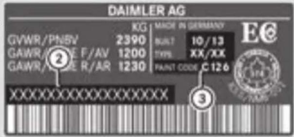
text_image
DAIMLER AG KG | MADE IN GERMANY GVWR/PNSV 2390 BUNT 10/13 GAWR/GNE F/AR 1200 TYPB XX/XX GAWR/GNE R/AR 1230 PAINT CODE C126 XXXXXXXXXXXXXX ② ③② Vehicle identification number (VIN)
③ Paint code
The data shown on the vehicle identification plate is used only as an example. This data is different for every vehicle and can deviate from the data shown here. The data applicable to the vehicle is found on the vehicle's identification plate.
Vehicle identification plate
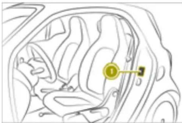
natural_image
Line drawing of a car interior showing seatbelt and dashboard (no text or symbols)① Vehicle identification plate position
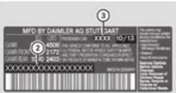
text_image
MFD BY DAIMLER AG STUTSART Eg LBS XXXX 10/1.3 2 4508 GARS FROM 2172 GARS REAR 10 40 2403 XXXXXX XXXXXX XXXXXX 3 The letter crop includes any or extended service including the communication - Top-Knowledge - Low-Energy Hardware - Clusters - Base Instruments Bancere Diamler Bancere Diamler Cable Recouls of Diamler Diamler Bancere Diamler of Diamler Diamler Bancere DiamlerUSA
② Vehicle model
③ Paint code
Dimensions and weights
Missing technical data was not available at the time of publication.
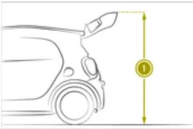
natural_image
Side profile diagram of a car showing front wheel, side arm, and height dimension (no text or symbols)| smart fortwo coupe elec- tric drive | Dimensions and weights |
| Opening height 1 | 73.0 in(1855 mm) |
| Vehicle length 106.1 in | (2695 mm) |
| Vehicle width including exterior mirrors | 74.5 in(1893 mm) |
| Vehicle width without exterior mirrors | 65.4 in(1663 mm) |
| Vehicle height 61.2 in | (1555 mm) |
| Wheelbase 73.7 in | (1873 mm) |
| Maximum ground clear-ance | 4.4 in(113 mm) |
| Maximum tailgate load | |
| Permissible roof load 0 lb | (0 kg) |
| smart fortwo cabrio elec-tric drive | Dimensions and weights |
| Height of open rear soft top | 61.1 in(1553 mm) |
| Vehicle length 106.1 in | (2695 mm) |
| Vehicle width including exterior mirrors | 74.5 in(1893 mm) |
| Vehicle height 61.1 in | (1553 mm) |
| Wheelbase 73.7 in | (1873 mm) |
| Maximum ground clear-ance | 4.3 in(110 mm) |
| Maximum tailgate load without side bars | |
| Maximum tailgate load with sidebars | |
| Permissible roof load 0 lb | (0 kg) |
Charging time
| High-voltage battery | |
| Model Lithium-ion | |
| Charging time(from 20 % to 100 %)at 32 A/240 V | Approx. 2 h30 min |
| Charging time(from 20 % to 100 %)at 12 A/120 V | Approx. 13 h |
Service products
Components and service products must be matched. Therefore, only use products tested and approved by Mercedes-Benz.
The following table lists all technical data for the service products of the vehicle. Further information on service products: http://bevo.mercedes-benz.com and in any smart center.
| Service products | Specifications |
| Corrosion inhibitor/antifreeze (▷ page 131) | Recommended: G40 |
| Windshield washer fluid (▷ page 132) | Temperatures above freezing point: mixing ratio of 1:100 MB SummerFit to water. Temperatures below freezing point: for the correct mixing ratio of MB WinterFit and water, please observe the information on the antifreeze container. |
Climate control system refrigerant
Important safety notes
Your vehicle's climate control system is filled with R-134a refrigerant.
The instruction label regarding the refrigerant type used can be found on the right hand side of the open service flap.
! Only the refrigerant R-134a and the PAG oil approved by Mercedes-Benz may be used. The approved PAG oil may not be mixed with any other PAG oil that is not approved for R-134a refrigerant. Otherwise, the climate control system may be damaged.
Service work, such as topping-up refrigerant or replacing components, may only be carried out at a qualified specialist workshop. All applicable regulations such as the SAE standard J639 must be adhered to.
Always have all work on the climate control system carried out at a qualified specialist workshop.
Refrigerant instruction label
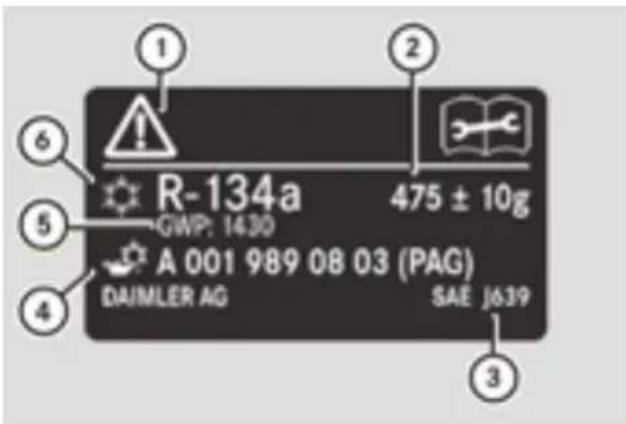
text_image
R-134a GWP: 1430 A 001 989 08 03 (PAG) DAIMLER AG SAE J639 475 ± 10g ① ② ③ ④ ⑤ ⑥Example: refrigerant instruction label
① Warning symbols
② Refrigerant filling capacity
③ Applicable standards
④ PAG oil part number
⑤ GWP value
⑥ Refrigerant type
Warning symbols ① advise you about:
- possible dangers
• having service work carried out at a qualified specialist workshop
Filling capacities
Model Refrigerant
| All models 20.3 ± 0.4 oz | ||
| (575 ± 10 g) | ||
The GWP value of the refrigerant R-134a is 1430.
Bulb types
The following table lists the correct bulb types of the vehicle:
| Bulb Model | |
| Low-beam/high-beam head-lamps | HB2 |
| Front fog lamps H 16 | |
| Turn signal PY 21 W | |
| Side turn signal lamps WY 5 W | |
| License plate lamp W 5 W | |
| Interior lighting W 5 W | |
Tail lamp
| Bulb Model | |
| Tail lamp, brake lamp and side marker lamp | P21 5 W |
| Rear fog lamp P21 W | |
| Backup lamp W 16 W | |
| Turn signal PY 21 W |
Fuse allocation
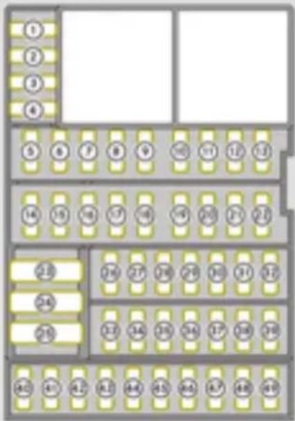
text_image
Floor plan diagram with numbered rooms and yellowish tiles, likely for a residential or commercial layout.| No. | Consumer Current Color coding | ||
| 1 | Starter motor 5 A Brown | ||
| 2 | Power steering control unit 5 A Brown | ||
| 3 | Multifunction lever 5 A Brown | ||
| 4 | Air bag 5 A Brown | ||
| 5 | Transmission control unit 25 A Cyan | ||
| 6 | Instrument cluster 10 A Red | ||
| 7 | Horn, alarm system 15 A Blue | ||
| 8 | Power supply control unit 10 A Red | ||
| 9 | Power supply control unit 10 A Red | ||
| 10 | Central control unit | 20 A | Yellow |
| 11 | Central control unit | 15 A Blue | |
| 12 | Central control unit | 10 A Red | |
| 13 | Central control unit | 15 A Blue | |
| 14 | Power windows (automatic reversing feature) | 30 A | Green |
| 15 | ESP®, transmission control unit | 5 A Brown | |
| 16 | Interior lighting | 10 A Red | |
| 17 | Immobilizer | 3 A | Violet |
| 18 | Electrical exterior mirror | 5 A Brown | |
| 19 | Brake lamps | 10 A Red | |
| 20 | Cruise control, radio, belt warning 15 A Blue | ||
| 21 | Not for smart electric drive: central control unit, fuel pump, injection | 15 A Blue | |
| 22 | Rear window wiper 15 A Blue | ||
| 23 | Only for smart electric drive: power supply con-trol unit | 40 A Orange | |
| 24 | -- | ||
| 25 | Power supply control unit 30 A Green | ||
| 26 | Radio 20 A Yellow | ||
| 27 | Daytime running lamps 5 A Brown | ||
| 28 | 12 V socket, cigarette lighter | 15 A Blue | |
| 29 | Power supply control unit | 5 A | Brown |
| 30 | Forward collision warning | 15 A Blue | |
| 31 | Rear fog lamp | -- | |
| 32 | Radio, central control unit | 15 A Blue | |
| 33 | Tail lamps, front fog lamps, hazard warning lamp button, locking button, headlamp range control, power windows, license plate lamp, radio, control unit for heating or climate control system, cruise control, limiter, parking aid button, program selector button, tailgate release, Lane Keeping Assist camera, automatic start/stop system but-ton | 25 A | Cyan |
| 34 | Power supply control unit 25 A Cyan | ||
| 35 | Headlamps, daytime running lamps | 25 A | Cyan |
| 36 | Left-hand low beam, central control unit | 10 A | Red |
| 37 | Right-hand low beam | 10 A | Red |
| 38 | Left-hand low beam, central control unit | 10 A | Red |
| 39 - 42 | -- | ||
| 43 | Exterior mirror heating | 5 A | Brown |
| 44 | Automatic reversing feature | 25 A | Cyan |
| 45 | Power supply control unit 25 A Cyan | ||
| 46 | Radio amplifier | 20 A Yellow | |
| 47 - 49 | -- | ||
Radio type approvals for the tire pressure monitor
Country Radio type approval number
| USA FCC ID: MRXMW2433A |
| FCC ID: MRXGG4 |
| FCC ID: MRXMC34MA4 |
| Canada IC: 2546A-MW2433A |
| IC: 2546A-GG4 |
| IC: 2546A-MC34MA4 |
Installing two-way radios and mobile phones

WARNING
The electromagnetic radiation from two-way radios can interfere with the vehicle electronics if two-way radios are manipulated or retrofitted incorrectly. This could jeopardize the operating safety of the vehicle. There is a risk of an accident.
You should have all work on electrical and electronic components carried out at a qualified specialist workshop.

WARNING
If you incorrectly operate two-way radios in the vehicle, the electromagnetic radiation may interfere with the vehicle electronics, for example if:
- the two-way radio is not connected to exterior antenna
- the exterior antenna is not correctly mounted or is not low-reflection
This could jeopardize the operating safety of the vehicle. There is a risk of an accident Have the low-reflection exterior antenna installed at a qualified specialist workshop. Always connect two-way radios to the low-reflection exterior antenna when operating in the vehicle.
! The operating permit may be invalidated if the instructions for installation and use of two-way radios are not observed.
In particular, the following conditions must be complied with:
- only approved wavebands may be used
- observe the maximum permissible output in these wavebands
- only approved antenna positions may be used
Excessive levels of electromagnetic radiation can cause damage to health. Using an exterior antenna takes into account current scientific discussions relating to the possible health hazards that may result from electromagnetic fields.
The following antenna positions may be used for the correct installation of two-way radios:
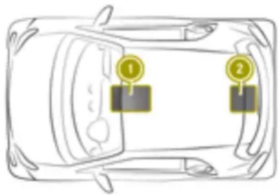
text_image
Diagram of a car with two labeled traffic indicators (1 and 2) on the side, likely indicating lane or sensor placement.① Front roof area
② Rear roof area
Use Technical Specification ISO/TS 21609 (Road Vehicles - EMC guidelines for installation of aftermarket radio frequency transmitting equipment) when retrofitting two-way radios. Comply with the legal requirements for add-on parts.
If your vehicle has installations for two-way radio equipment, use the power supply and antenna connections intended for use in the basic wiring. Be sure to observe the manufacturer's additional instructions during installation.
Deviations with respect to wavebands, maximum transmission outputs or antenna positions must be approved by smart.
i Damage or consequential damage resulting from retrofitting two-way radios in the
vehicle, is not covered by the smart warranty.
The maximum transmission output (PEAK) at the base of the antenna must not exceed the following values:
| Waveband Maximum | transmission output |
| Tetra | 20 W |
| 380 - 410 MHz | |
| Mobile communications generation 2G/3G/4G | 6 W |
The following can be used in the vehicle without restrictions:
- Two-way radios with a maximum transmission output of up to 100 mW
• Mobile phones (2G/3G/4G)
There is no restriction for antenna positions on the outside of the vehicle for the following wavebands:
- Tetra
- Mobile communications (2G/3G/4G)