
NVR-0437 - Video recorder LEVELONE - Free user manual and instructions
Find the device manual for free NVR-0437 LEVELONE in PDF.


| Product Type | Network Video Recorder (NVR) |
| Brand | LevelOne |
| Model | NVR-0437 |
| Channels | 4 |
| Video Compression | H.265, H.264 |
| Recording Resolution | Up to 8MP (4K) |
| Audio Support | Yes, audio in/out |
| PoE Support | Yes, 4 PoE ports (802.3af/at) |
| Storage Capacity | 1 SATA HDD up to 10TB |
| Network Interface | 1x Gigabit Ethernet |
| USB Ports | 2x USB 2.0 |
| HDMI Output | Yes, up to 3840x2160 |
| Dimensions (W x D x H) | 260 x 220 x 45 mm |
| Weight | 1.2 kg (without HDD) |
| Power Supply | DC 12V, 2A |
| Power Consumption | ≤ 10W (without HDD) |
| Operating Temperature | -10°C to 55°C |
| Compatible Cameras | ONVIF, LevelOne IP cameras |
| Remote Access | Via Web, App (iOS/Android) |
| Maintenance | Regular HDD health check, firmware updates |
| Safety | CE, FCC compliant |
| Spare Parts & Repairability | HDD, power adapter, replaceable fan |
| Warranty | 2 years limited |
Frequently Asked Questions - NVR-0437 LEVELONE
User questions about NVR-0437 LEVELONE
0 question about this device. Answer the ones you know or ask your own.
Ask a new question about this device
Download the instructions for your Video recorder in PDF format for free! Find your manual NVR-0437 - LEVELONE and take your electronic device back in hand. On this page are published all the documents necessary for the use of your device. NVR-0437 by LEVELONE.
USER MANUAL NVR-0437 LEVELONE
natural_image
Abstract red geometric shape with a white diagonal stripe on the left (no text or symbols)Guarding Vision Client Software
User Manual
Legal Information
User Manual
About this Manual
The Manual includes instructions for using and managing the product. Pictures, charts, images and all other information hereinafter are for description and explanation only. The information contained in the Manual is subject to change, without notice, due to firmware updates or other reasons. Please find the latest version in the company website.
Please use this user manual under the guidance of professionals.
Disclaimer
TO THE MAXIMUM EXTENT PERMITTED BY APPLICABLE LAW, THE PRODUCT DESCRIBED, WITH ITS HARDWARE, SOFTWARE AND FIRMWARE, IS PROVIDED "AS IS", WITH ALL FAULTS AND ERRORS, AND OUR COMPANY MAKES NO WARRANTIES, EXPRESS OR IMPLIED, INCLUDING WITHOUT LIMITATION, MERCHANTABILITY, SATISFACTORY QUALITY, FITNESS FOR A PARTICULAR PURPOSE, AND NON-INFRINGEMENT OF THIRD PARTY. IN NO EVENT WILL OUR COMPANY, ITS DIRECTORS, OFFICERS, EMPLOYEES, OR AGENTS BE LIABLE TO YOU FOR ANY SPECIAL, CONSEQUENTIAL, INCIDENTAL, OR INDIRECT DAMAGES, INCLUDING, AMONG OTHERS, DAMAGES FOR LOSS OF BUSINESS PROFITS, BUSINESS INTERRUPTION, OR LOSS OF DATA OR DOCUMENTATION, IN CONNECTION WITH THE USE OF THIS PRODUCT, EVEN IF OUR COMPANY HAS BEEN ADVISED OF THE POSSIBILITY OF SUCH DAMAGES.
REGARDING TO THE PRODUCT WITH INTERNET ACCESS, THE USE OF PRODUCT SHALL BE WHOLLY AT YOUR OWN RISKS. OUR COMPANY SHALL NOT TAKE ANY RESPONSIBILITES FOR ABNORMAL OPERATION, PRIVACY LEAKAGE OR OTHER DAMAGES RESULTING FROM CYBER ATTACK, HACKER ATTACK, VIRUS INSPECTION, OR OTHER INTERNET SECURITY RISKS; HOWEVER, OUR COMPANY WILL PROVIDE TIMELY TECHNICAL SUPPORT IF REQUIRED.
SURVEILLANCE LAWS VARY BY JURISDICTION. PLEASE CHECK ALL RELEVANT LAWS IN YOUR JURISDICTION BEFORE USING THIS PRODUCT IN ORDER TO ENSURE THAT YOUR USE CONFORMS THE APPLICABLE LAW. OUR COMPANY SHALL NOT BE LIABLE IN THE EVENT THAT THIS PRODUCT IS USED WITH ILLEGITIMATE PURPOSES.
IN THE EVENT OF ANY CONFLICTS BETWEEN THIS MANUAL AND THE APPLICABLE LAW, THE LATER PREVAILS.
Symbol Conventions
The symbols that may be found in this document are defined as follows.
| Symbol Description | |
 Danger Danger | Indicates a hazardous situation which, if not avoided, will or could result in death or serious injury. |
 Caution Caution | Indicates a potentially hazardous situation which, if not avoided, could result in equipment damage, data loss, performance degradation, or unexpected results. |
 Note Note | Provides additional information to emphasize or supplement important points of the main text. |
Contents
Chapter 1 Introduction and Overview ...... 1
1.1 Introduction ...... 1
1.2 Running Environment .... 1
1.3 Summary of Changes 2
Chapter 2 User Registration and Login .... 3
2.1 Register a User .... 3
2.2 Login 4
2.3 Customize Displayed Modules on Control Panel 4
Chapter 3 Device Management ....6
3.1 Activate Devices 6
3.2 Add Device 7
3.2.1 Add Online Device 7
3.2.2 Add Device by IP Address or Domain Name 11
3.2.3 Add Devices by IP Segment 12
3.2.4 Add Device by Cloud P2P 14
3.2.5 Add Device by EHome Account 15
3.2.6 Add Device by Serial Port 15
3.2.7 Add Device by IP Server 16
3.2.8 Add Device by HiDDNS 17
3.2.9 Import Devices in a Batch 18
3.3 Edit Device's Network Information 20
3.4 Restore/Reset Device Password 21
3.4.1 Reset Device Password 21
3.4.2 Restore Device's Default Password 22
3.5 Check Device's Online Users 23
3.6 Check Device's QR Code 23
3.7 Upgrade Device Firmware Version 24
Chapter 4 Cloud P2P ...... 26
4.1 Register a Cloud P2P Account 26
4.2 Log in to Cloud P2P Account 27
4.3 Device Management 27
4.3.1 Add Device to Cloud P2P Account 27
4.3.2 Edit Camera Parameters ...... 29
Chapter 5 Group Management .... 31
5.1 Add Group 31
5.2 Import Resources to Group 31
5.3 Edit Channel Parameters ...... 32
5.4 Remove Channel from Group 33
5.5 Delete Group 34
Chapter 6 Live View ...... 35
6.1 Start and Stop Live View 35
6.1.1 Start Live View for One Camera 35
6.1.2 Start Live View for Camera Group 36
6.1.3 Start Live View in Default View Mode 37
6.1.4 Start Live View in Custom View Mode 38
6.1.5 Stop Live View 38
6.2 Auto-Switch in Live View 39
6.2.1 Auto-Switch Cameras in a Group 39
6.2.2 Auto-Switch All Cameras in Default View 40
6.2.3 Auto-Switch Custom Views 40
6.3 PTZ Control 40
6.3.1 Configure Preset 41
6.3.2 Configure Pattern 42
6.3.3 Configure Patrol 43
6.4 Customize Window Division 43
6.5 Manually Record and Capture 44
6.5.1 Manually Record Video 44
6.5.2 View Local Videos 45
6.5.3 Capture Pictures 45
6.5.4 View Captured Pictures 46
6.6 Instant Playback 47
6.7 Live View for Fisheye Camera 47
6.7.1 Perform Live View in Fisheye Mode 47
6.7.2 PTZ Control in Fisheye Mode 48
6.8 Perform Master-Slave Linkage 50
6.8.1 Configure Master-Slave Tracking Rule 50
6.8.2 Enable Master-Slave Tracking 52
6.9 Live View for Thermal Camera 53
6.9.1 View Fire Source Information during Live View 53
6.9.2 Show Temperature Information on Live View Image 54
6.9.3 Manually Measure Temperature on Points 54
6.10 More Functions 55
Chapter 7 Remote Storage Configuration .... 57
7.1 Store Picture and Video on DVR, NVR, or Network Camera 57
7.2 Store Picture and Video on Storage Device 59
7.2.1 Activate Storage Server 59
7.2.2 Add Storage Server to Client 60
7.2.3 Format Storage Server's HDD 60
7.2.4 Configure Storage Settings 61
7.3 Configure Recording Schedule Template 62
7.4 Configure Capture Schedule Template 63
Chapter 8 Remote Playback 65
8.1 Switch Video Stream for Playback 65
8.2 Normal Playback 65
8.2.1 Search Video Files 68
8.2.2 Play Video Files 68
8.3 Alarm Input Playback 69
8.3.1 Search Video Files 69
8.3.2 Play Video Files 70
8.4 Event Playback 70
8.4.1 Search Video Files 70
8.4.2 Play Video Files 71
8.5 ATM Playback 72
8.5.1 Search Video Files 72
8.5.2 Play Video Files 73
8.6 POS Playback 73
8.6.1 Search Video Files 73
8.6.2 Play Video Files 74
8.7 VCA Playback 75
8.8 Synchronous Playback 76
8.9 Fisheye Playback 77
Chapter 9 Download Video Files 79
9.1 Download by File 79
9.2 Download by Date 79
9.3 Download by Tag 80
9.4 Download for Multiple Cameras 81
Chapter 10 Event and Alarm 82
10.1 Alarm Configuration 82
10.1.1 Configure Motion Detection Alarm 82
10.1.2 Configure Video Tampering Alarm 84
10.1.3 Configure Video Loss Alarm 86
10.1.4 Configure Audio Exception Alarm 87
10.1.5 Configure Face Detection Alarm 89
10.1.6 Configure Line Crossing Detection Alarm 91
10.1.7 Configure Alarm Input Alarm 93
10.1.8 Configure Device Exception Alarm 94
10.1.9 Configure Arming Schedule 95
10.1.10 Configure Custom Arming Schedule 96
10.2 View Alarm and Event Information 97
10.2.1 Enable Receiving Alarms from Devices 97
10.2.2 View Alarm Information 97
10.2.3 View Event Information 98
10.2.4 View Pop-up Alarm Information 99
10.2.5 Acknowledge Fire Source Detection Alarm 100
Chapter 11 Map Management ...... 102
11.1 Add Map 102
11.2 Manage Hot Spot 102
11.2.1 Add Camera as Hot Spot 103
11.2.2 Add Alarm Input as Hot Spot 103
11.2.3 Add Alarm Output as Hot Spot 104
11.2.4 Edit Hot Spot 104
11.2.5 Preview Hot Spot 105
11.3 Manage Hot Region 106
11.3.1 Add Hot Region 106
11.3.2 Edit Hot Region 107
11.3.3 Preview Hot Region 107
Chapter 12 Statistics ...... 109
12.1 Heat Map Report 109
12.2 People Counting Report .... 110
12.3 Counting Report 112
12.4 Road Traffic Report 113
12.5 Face Picture Retrieval 114
12.5.1 Search Face Picture by Uploaded Picture 114
12.5.2 Search Face Picture by Event 117
12.5.3 Search Face Picture by Person Name 119
12.6 License Plate Retrieval 120
12.7 View Behavior Analysis Related Pictures and Videos 121
12.8 Human Body Picture Retrieval 122
12.9 Vehicle Retrieval 124
12.10 Queue Management 125
12.10.1 Queuing-Up Time Analysis 126
12.10.2 Queue Status Analysis 129
12.11 Face Recognition Check-in 132
12.12 View People Counting in Intersections Report 133
Chapter 13 View Face Picture Comparison Alarm .... 135
13.1 View Captured Face Picture 135
13.2 View Matched Face Pictures .... 137
13.3 View Face Picture Comparison Alarm Logs 137
13.3.1 Search Face Picture Comparison Alarm Logs 138
13.3.2 Open Face Picture Comparison Alarm Logs 138
Chapter 14 Show AI Information .... 140
14.1 Set Cameras for Showing AI Information 141
14.2 Set List Types for Face Picture Libraries 142
Chapter 15 Forward Video Stream through Stream Media Server 143
15.1 Import Certificate to Stream Media Server 143
15.2 Add Stream Media Server 144
15.2.1 Add Stream Media Server by IP Address 144
15.2.2 Add Stream Media Servers by IP Segment 145
15.3 Add Cameras to Stream Media Server to Forward Video Stream 146
Chapter 16 Video Wall ...... 147
16.1 Manage Encoding Device 147
16.1.1 Add Encoding Device 147
16.1.2 Add Third-Party Encoding Device 147
16.2 Manage Decoding Device 149
16.2.1 Add Decoding Device 149
16.2.2 Edit Output of Decoding Device 149
16.3 Configure Video Wall Settings 150
16.3.1 Add Video Wall 150
16.3.2 Link Decoding Output with Video Wall 151
16.4 Display Video on Video Wall 152
16.4.1 Decode and Display 152
16.4.2 Perform Windowing and Roaming 154
16.4.3 Display Playback on Video Wall 156
16.4.4 Configure Auto-Switch Decoding 157
Chapter 17 Security Control Panel ...... 159
17.1 Configure Client Linkage for Zone Event 159
17.2 Remotely Control Security Control Panel 160
17.2.1 Remotely Control Partitions 160
17.2.2 Remotely Control Zones 161
17.3 Display Zone on Map 162
17.4 Handle Alarms 163
17.4.1 View Real-Time Alarm 163
17.4.2 Search History Alarm 164
17.4.3 Handle Panic Alarm 164
Chapter 18 Pyronix Control Panel ...... 166
18.1 Add Pyronix Control Panel 166
18.2 Authorize Client via PyronicCloud 168
18.2.1 Create PyronixCloud Account 168
18.2.2 Connect Device to PyronixCloud 169
18.2.3 Authorize Client 170
18.3 Configure Client Linkage for Pyronix Control Panel Event 171
18.4 Remotely Control Pyronix Control Panel 172
18.4.1 Remotely Control Partition 172
18.4.2 Remotely Control Zone 173
18.4.3 Remotely Control Connected Alarm Output 173
Chapter 19 Access Control .... 175
19.1 Select Application Scenario 175
19.2 Configure Device Parameters 176
19.2.1 Set Network Parameters ...... 176
19.2.2 Set Device Capture Parameters 178
19.2.3 Set RS-485 Parameters 179
19.2.4 Set Weigand Parameters 180
19.2.5 Set Multiple NIC Parameters 180
19.2.6 Set Face Recognition Terminal Parameters 181
19.2.7 Authenticate M1 Card Encryption 182
19.3 Manage Organization 182
19.4 Manage Person Information 183
19.4.1 Add Single Person 183
19.4.2 Import and Export Person Identify Information 192
19.4.3 Get Person Information from Access Control Device 194
19.4.4 Issue Cards to Person in Batch 194
19.4.5 View Records of Face Modeling Failed 195
19.4.6 Search Person Information 196
19.4.7 Report Card Loss 197
19.4.8 Set Card Enrollment Station 198
19.5 Configure Schedule and Template 199
19.5.1 Add Week Schedule 199
19.5.2 Add Holiday Schedule 200
19.5.3 Add Template 201
19.6 Manage Permission 202
19.6.1 Assign Permission to Person 202
19.6.2 Search Assigned Permission 203
19.7 Configure Advanced Functions 204
19.7.1 Configure Access Control Parameters 204
19.7.2 Configure Card Reader Authentication Mode and Schedule 212
19.7.3 Configure Multiple Authentication 213
19.7.4 Configure Opening Door with First Card 215
19.7.5 Configure Anti-Passback 216
19.7.6 Configure Cross-Controller Anti-passing Back 217
19.7.7 Configure Multi-door Interlocking 221
19.7.8 Configure Authentication Password 222
19.7.9 Configure Relay for Elevator Controller 222
19.7.10 Configure Custom Wiegand Rule 225
19.7.11 Configure Person in Blacklist 226
19.8 Search Access Control Event 227
19.8.1 Search Access Control Events Stored in Local Client 228
19.8.2 Search Access Control Events Stored on Device 228
19.9 Configure Access Control Alarm Linkage 229
19.9.1 Configure Client Linkage for Access Control Alarm 229
19.9.2 Configure Device Linkage for Access Control Alarm 230
19.9.3 Configure Device Linked Actions for Card Swiping 232
19.9.4 Configure Device Linkage for Mobile Terminal's MAC Address 233
19.9.5 Configure Cross-Device Linkage 234
19.10 Manage Access Control Point Status 236
19.10.1 Group Access Control Points 236
19.10.2 Control Door Status 237
19.10.3 Control Elevator Status 238
19.10.4 Check Real-time Access Records 239
19.11 Control Door during Live View 240
19.12 Display Access Control Point on E-map 240
19.13 Two-way Audio 241
19.13.1 Call Client from the Device 241
19.13.2 Call Device from Client 242
Chapter 20 Time and Attendance 243
20.1 Manage Shift Schedule 243
20.1.1 Add Time Period 243
20.1.2 Add Shift 244
20.1.3 Set Department Schedule 244
20.1.4 Set Person Schedule 245
20.1.5 Set Temporary Schedule 246
20.1.6 Check and Edit Shift Schedule 247
20.2 Manually Correct Check-in/out Record 247
20.3 Add Leave and Business Trip 248
20.4 Calculate Attendance Data 249
20.4.1 Automatically Calculate Attendance Data 249
20.4.2 Manually Calculate Attendance Data 250
20.5 Configure Advanced Settings 250
20.5.1 Configure Basic Parameters 250
20.5.2 Configure Attendance Rule 251
20.5.3 Configure Attendance Check Point 251
20.5.4 Configure Holiday 252
20.5.5 Configure Leave Type 255
20.6 View Attendance Report 255
20.6.1 Get an Overview of Employees' Attendance Data 256
20.6.2 Search Employees' Detailed Attendance Data 256
20.6.3 Search Employees' Abnormal Attendance Data 257
20.6.4 Search Employees' Overtime Working Data 258
20.6.5 Check Employees' Card Swiping Logs 259
20.6.6 Generate Attendance Report 260
Chapter 21 Video Intercom 262
21.1 Manage Calls between Client Software and Indoor/Door Station 262
21.1.1 Call Indoor Station from Client 262
21.1.2 Call Client from Indoor Station/Door Station 263
21.1.3 View Live Video of Door Station and Outer Door Station 264
21.2 View Real-Time Call Logs 265
21.3 Release Notice to Resident 265
21.4 Search Video Intercom Information 266
21.4.1 Search Call Logs 266
21.4.2 Search Unlocking Logs 266
21.4.3 Search Notice 267
Chapter 22 Log Management ...... 268
22.1 Search Logs 268
22.1.1 Search Client Logs 268
22.1.2 Search Connected Device Logs 268
22.2 Filter Logs 269
22.3 Back Up Logs 269
22.4 Export Pictures 270
Chapter 23 Account Management ...... 271
Chapter 24 System Configuration ...... 273
24.1 Set General Parameters 273
24.2 Set Live View and Playback Parameters 274
24.3 Set Image Parameters 275
24.4 Set File Saving Path 277
24.5 Set Icons Shown on Toolbar 277
24.6 Set Keyboard and Joystick Shortcuts 278
24.7 Set Alarm Sound 279
24.8 Set Email Parameters 279
24.9 Set Video Intercom Parameters 280
24.10 Set Access Control Parameters 281
24.11 Manage Security Certificate 281
24.11.1 Export Certificate from Client 281
24.11.2 Import Certificate to Client 282
Appendix A. Custom Wiegand Rule Descriptions 283
Appendix B. Troubleshooting 285
B.1 Failed to get the live view of a certain device. 285
B.2 Local recording and remote recording are confused. 285
B.3 Failed to download the video files or the downloading speed is too slow. 285
Appendix C. FAQ (Frequently Asked Questions) 287
C.1 During live view, why an error message with error code 91 prompts ? ...... 287
C.2 During live view, why the image is blurred or not fluent? 287
C.3 Why the memory leaked and the client crashed after running for a while? 287
C.4 During live view, when getting stream via the Stream Media Server, why an error message with error code 17 prompts? 288
Appendix D. Error Code 289
Chapter 1 Introduction and Overview
Guarding Vision Client Software is a versatile security management software for the DVRs, NVRs, IP cameras, encoders, etc.
1.1 Introduction
The software provides multiple functionalities, including real-time live view, video recording, remote search and playback, file backup, alarm receiving, etc., for the connected devices to meet the needs of monitoring task. With the flexible distributed structure and easy-to-use operations, the client software is widely applied to the surveillance projects of medium or small scale.
This user manual describes the functions, configurations and operation steps of the client software. To ensure the properness of usage and stability of the software, refer to the contents below and read the manual carefully before installation and operation.
1.2 Running Environment
The followings are the recommended running environment for installing the client software.
Operating System
Microsoft Windows 7/Windows 8.1/Windows 10 (32-bit or 64-bit)
Microsoft Windows XP SP3 (32-bit)
Microsoft Windows 2008 R2/Windows Server 2012 (64-bit)
CPU
Intel Pentium IV 3.0 GHz or Above
Memory
2 GB or Above
Video Card
RADEON X700 Series or Above
GPU
256 MB or Above

Note
- For high stability and good performance, the above system requirements must be met.
- The software does not support 64-bit operating system; the above mentioned 64-bit operating system refers to the system which supports 32-bit applications as well.
- Hardware decoding function is only supported by the operating systems with the version after Windows XP.
Chapter 2 User Registration and Login
You should register a super user and then you can login the client with the super user account as administrator.
2.1 Register a User
For the first time using the client software, you should to register a super user for login.
Perform the following steps to register a super user for login.
Steps
- After installing the client, double click to run the software.
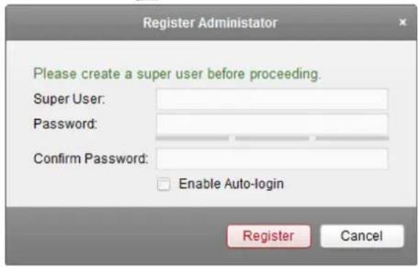
text_image
Register Administrator Please create a super user before proceeding. Super User: Password: Confirm Password: Enable Auto-login Register CancelFigure 2-1 Register a User
- Create a user name and password for the super user.

Note
- A user name cannot contain any of the following characters: / \ : * ? "< > |. And the length of the password cannot be less than 6 characters.
- The software will judge password strength automatically. For your privacy, we strongly recommend changing the password to something of your own choosing (using a minimum of 8 characters, including upper case letters, lower case letters, numbers, and special characters) in order to increase the security of your product.
-
Proper configuration of all passwords and other security settings is the responsibility of the installer and/or end-user.
-
Confirm the password.
- Optional: Check the Enable Auto-login checkbox to log into the software automatically.
- Click Register to register the super user.
You can log into the software as super user.
What to do next
Log into the client. Refer to Login for details.
2.2 Login
You can log in to the client software to perform the operations, such as live view, playback, and so on.
Perform this task if you want to log in to the clientsoftware.
Steps
- Run the client software to open Login dialog.
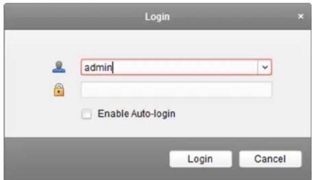
text_image
Login admin Enable Auto-login Login CancelFigure 2-2 Login
-
Input the user name and password you registered.
-
Optional: Check Enable Auto-login checkbox to log in to the software automatically for next running.
-
Click Login to log in to the client software.
After logging in to the client software, you can open the wizards (including video wizard, video wall wizard, security control panel wizard, access control and video intercom wizard, and attendance wizard), to guide you to add the device and do other settings and operations.
2.3 Customize Displayed Modules on Control Panel
For the first time running the software, you can customize the modules displayed on the Operation and Control area of the control panel.
Perform this task when you need to customize the modules displayed on control panel.
Steps
- Click Modules Customization on the control panel to open Modules Customization page.
- Check the module(s) to display them on the control panel according to the actual needs.
- Click OK.

Note
• After adding the access control device in Device Management module, the Access Control, Status Monitor, and Time and Attendance module display on the control panel automatically.
• After adding the security control panel in Device Management module, the Security Control Panel and Real-time Alarm modules display on the control panel automatically.
Chapter 3 Device Management
You can manage devices on the client, including adding, editing, and deleting the devices. You can also perform operations such as checking device's online users and checking devices' QR codes.
3.1 Activate Devices
For some devices, you are required to create the password to activate them before they can be added to the software and work properly.
Perform this task to activate device.
Steps

Note
This function should be supported by the device.
- Enter the Device Management page.
- Check the device status (shown on Security column) and select an inactive device on the Device for Management or Online Device area.
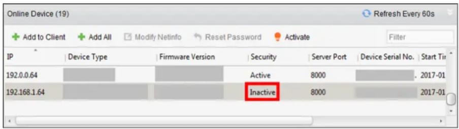
text_image
Online Device (19) Add to Client Add All Modify Netinfo Reset Password Activate Filter IP Device Type Firmware Version Security Server Port Device Serial No. Start Tin 192.0.0.64 Active 8000 2017-01 192.168.1.64 Inactive 8000 2017-01Figure 3-1 Online Device
- Click Activate to open the Activation dialog.
- Create a password in the password field, and confirm the password.

Caution
The password strength of the device can be automatically checked. We highly recommend you change the password of your own choosing (using a minimum of 8 characters, including at least three kinds of following categories: upper case letters, lower case letters, numbers, and special characters) in order to increase the security of your product. And we recommend you reset your password regularly, especially in the high security system, resetting the password monthly or weekly can better protect your product.
Proper configuration of all passwords and other security settings is the responsibility of the installer and/or end-user.
-
Optional: For NVR device connected with inactive network camera(s), create a password in Network Camera's Default Passowrd field for activating the network camera(s) via NVR.
-
Optional: Enable Cloud P2P service when activating the device if the device supports.
1) Check Enable Cloud P2P to open the Note dialog.
2) Create a verification code.
3) Confirm the verification code.
4) Click Terms of Service and Privacy Policy to read the requirements.
5) Click OK to enable the Cloud P2P service.
- Click OK to activate the device.

If the device(s) you selected supports resetting password via GUID file, security question or reserved email, you can export the GUID file, set the security question or reserve an email address for further password reset.
3.2 Add Device
After running the client, devices including network cameras, video encoders, DVRs, NVRs, decoders, security control panels, video intercom devices, access control devices, etc., should be added to the client for the remote configuration and management, such as live view, playback, alarm settings, etc.
After adding device(s), you can select a device and click Remote Configuration to configure further parameters of the selected device if needed. You can also
i Note
- For some models of devices, you can open its general or advanced parameters configuration window. To open the original remote configuration window, press CTRL and click Remote Configuration.
- For details about the settings, refer to the user manual of the devices.
After adding access control devices and CVR, you can select access control device and CVR from the list and click Device Status to view the device status including recording status, signal status, hardware status, etc.
i Note
For CVR, You can click Device Status to view the recording status and ANR (Automatic Network Replenishment) recording status.
3.2.1 Add Online Device
The active online devices in the same local subnet with the client software will be displayed on the Online Device area. You can click Refresh Every 60s to refresh the information of the online devices.
Add Single Online Device
You can add single online device to the client software.
Perform this task to add single online device to the client software.
Steps
-
Enter the Device Management module.
-
Click Device tab and select Device as the device type to display the Online Device area.
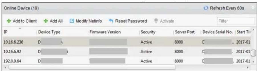
text_image
Online Device (19) + Add to Client + Add All Modify Netinfo Reset Password Activate Filter IP Device Type Firmware Version Security Server Port Device Serial No. Start Tii 10.16.6.236 D Active 8000 C 2017-01 10.16.6.92 D Active 8000 D 2017-01 192.0.0.64 D Active 8000 D 2017-01Figure 3-2 Online Device
- Select an online device from the Online Device area.
i Note
For the inactive device, you need to create the password for it before you can add the device properly. For detailed steps, refer to Activate Devices.
-
Click Add to Client to open the device adding window.
-
Input the required information.
Address
Input the device's IP address. The IP address of the device is obtained automatically in this adding mode.
Port
The default value is 8000.
User Name
By default, the user name is admin.
Password
Input the device password.
Caution
The password strength of the device can be automatically checked. We highly recommend you change the password of your own choosing (using a minimum of 8 characters, including at least three kinds of following categories: upper case letters, lower case letters, numbers, and special characters) in order to increase the security of your product. And we recommend
you reset your password regularly, especially in the high security system, resetting the password monthly or weekly can better protect your product.
Proper configuration of all passwords and other security settings is the responsibility of the installer and/or end-user.
-
Optional: Check Synchronize Device Time to synchronize the device time with the PC running the client after adding the device to the client.
-
Optional: Check Export to Group to create a group by the device name.

Note
You can import all the channels of the device to the corresponding group by default.
- Optional: Add the offline devices.
1) Check Add Offline Device.
2) Input the required information, including the device channel number and alarm input number.
3) Click Add.
When the offline device comes online, the software will connect it automatically.
- Click Add to add the device.
Add Multiple Online Devices
You can add multiple online devices to the client software.
Perform this task if you need to add multiple online devices to the client software.
Steps
- Enter the Device Management module.
- Click Device tab and select Device as the device type to display the Online Device area.
- Click and hold Ctrl key to select multiple devices.

Note
For the inactive device, you need to create the password for it before you can add the device properly. For detailed steps, refer to Activate Devices.
-
Click Add to Client to open the device adding window.
-
Input the required information.
User Name
By default, the user name is admin.
Password
Input the device password.
Caution
The password strength of the device can be automatically checked. We highly recommend you change the password of your own choosing (using a minimum of 8 characters, including at least three kinds of following categories: upper case letters, lower case letters, numbers, and special characters) in order to increase the security of your product. And we recommend you reset your password regularly, especially in the high security system, resetting the password monthly or weekly can better protect your product.
Proper configuration of all passwords and other security settings is the responsibility of the installer and/or end-user.
-
Optional: Check Synchronize Device Time to synchronize the time of the devices with the PC running the client after adding the devices to the client.
-
Optional: Check Export to Group to create a group by the device name.
i Note
You can import all the channels of the device to the corresponding group by default.
- Click Add to add the devices.
Add All Online Devices
You can add all online devices to the client software.
Perform this task if you need to add all online devices to the client software.
Steps
-
Enter the Device Management page.
-
Click Device tab and select Device as the device type to display the Online Device area.
-
Click Add All to open the device adding window.
i Note
For the inactive device, you need to create the password for it before you can add the device properly. For detailed steps, refer to Activate Devices.
- Input the user name and password.
User Name
By default, the user name is admin.
Password
Input the device password.
Caution
The password strength of the device can be automatically checked. We highly recommend you change the password of your own choosing (using a minimum of 8 characters, including at least
three kinds of following categories: upper case letters, lower case letters, numbers, and special characters) in order to increase the security of your product. And we recommend you reset your password regularly, especially in the high security system, resetting the password monthly or weekly can better protect your product.
Proper configuration of all passwords and other security settings is the responsibility of the installer and/or end-user.
-
Optional: Check Synchronize Device Time to synchronize the time of the devices with the PC running the client after adding the devices to the client.
-
Optional: Check Export to Group to create a group by the device name.

You can import all the channels of the device to the corresponding group by default.
- Click Add to add the devices.
3.2.2 Add Device by IP Address or Domain Name
You can add device by IP address or domain name.
Perform this task if you need to add device by IP address or domain name.
Steps
-
Open the Device Management module.
-
Click Device tab and select Device as the device type.
-
Click Add to open the Add window.
-
Select IP/Domain as the adding mode.
-
Enter the required information, including nickname, IP address, port number, user name, and password.
Address
Input the device IP address or domain name.
Port
Input the device port No. The default value is 8000. If you check Transmit Encryption(TLS), the value should be Enhanced SDK service port No. of the device.
User Name
Enter the device user name. By default, the user name is admin.
Password
Enter the device password.
Caution
The password strength of the device can be automatically checked. We highly recommend you change the password of your own choosing (using a minimum of 8 characters, including at least three kinds of following categories: upper case letters, lower case letters, numbers, and special characters) in order to increase the security of your product. And we recommend you reset your password regularly, especially in the high security system, resetting the password monthly or weekly can better protect your product.
Proper configuration of all passwords and other security settings is the responsibility of the installer and/or end-user.
- Optional: Enable Transmit Encryption function for security purpose using TLS (Transport Layer Security) protocol.
i Note
This function should be supported by the device.
1) Check Transmit Encryption(TLS).
2) Click Open Certificate Folder to open the default folder.
3) Copy the certificate file exported from the device to this default directory.
iNote
You can log into the device to get the certificate file by web browser.
-
Optional: Check Synchronize Device Time to synchronize the device time with the PC running the client after adding the device to the client.
-
Optional: Check Export to Group to create a group by the device name.
i Note
You can import all the channels of the device to the corresponding group by default.
- Optional: Add the offline devices.
1) Check Add Offline Device.
2) Input the required information, including the device channel number and alarm input number.
3) Click Add.
When the offline device comes online, the software will connect it automatically.
- Click Add to add the device.
3.2.3 Add Devices by IP Segment
If you want to add devices of which the IP addresses are within an IP segment, you can specify the start IP address and end IP address, user name, password, and other parameters to add them.
Perform this task when you need to add devices to the client by IP segment.
Steps
- Enter the Device Management module.
- Click Device tab and select Device as the device type.
- Click Add to open the Add window.
- Select IP Segment as the adding mode.
- Enter the required information.
Start IP
Input a start IP address.
End IP
Input an end IP address in the same network segment with the start IP.
Port
Enter the device port No. The default value is 8000. If you check Transmit Encryption(TLS), the value should be Enhanced SDK service port No. of the device.
User Name
By default, the user name is admin.
Password
Input the device password.

The password strength of the device can be automatically checked. We highly recommend you change the password of your own choosing (using a minimum of 8 characters, including at least three kinds of following categories: upper case letters, lower case letters, numbers, and special characters) in order to increase the security of your product. And we recommend you reset your password regularly, especially in the high security system, resetting the password monthly or weekly can better protect your product.
Proper configuration of all passwords and other security settings is the responsibility of the installer and/or end-user.
- Optional: Enable Transmit Encryption function for security purpose using TLS (Transport Layer Security) protocol.

This function should be supported by the device.
1) Check Transmit Encryption(TLS).
2) Click Open Certificate Folder to open the default folder.
3) Copy the certificate file exported from the device to this default directory.

You can log into the device to get the certificate file by web browser.
-
Optional: Check Synchronize Device Time to synchronize the device time with the PC running the client after adding the device to the client.
-
Optional: Check Export to Group to create a group by the device name.

You can import all the channels of the device to the corresponding group by default.
- Optional: Add offline devices to the client.
1) Check Add Offline Device.
2) Enter the required information, including the device channel number and alarm input number.
3) Click Add.
When the offline device comes online, the software will connect it automatically.
- Click Add to add the device.
3.2.4 Add Device by Cloud P2P
You can add the devices to the client via Cloud P2P domain.
Before You Start
Add the devices to Cloud P2P account first.
Perform this task when you need to add device by Cloud P2P domain.
Steps
- Log in to the Cloud P2P account.
- Open the Device Management module.
- Click Device tab and select Device as the device type.
- Click Add to open the Add window.
- Select Cloud P2P as the adding mode.
The device(s) under the Cloud P2P account will be displayed.
-
Select the device(s).
-
Input the device user name and password.

By default, the device user name is admin and the password is created when you activate the device.
-
Optional: Check Synchronize Device Time to synchronize the device time with the PC running the client after adding the device to the client.
-
Optional: Check Export to Group to create a group by the device name.

By default, you can import all the channels of the device to the corresponding group.
- Click Add to add the device.
3.2.5 Add Device by EHome Account
You can add access control device connected via EHome protocol by inputting the EHome account.
Before You Start
Set the network center parameter first. For details, refer to Set Network Parameters.
Perform this task if you need to add devices by EHome account.
Steps
- Enter the Device Management module.
- Click Device tab and select Device as the device type.
- Click Add to open the Add window.
- Select EHome as the adding mode.
- Input the required information.
Account
Input the account name registered on EHome protocol.
- Optional: Check Synchronize Device Time to synchronize the device time with the PC running the client after adding the device to the client.
- Optional: Check Export to Group to create a group by the device name.
- Optional: Add the offline devices.
1) Check Add Offline Device.
2) Input the required information, including the device channel number and alarm input number.
3) Click Add.

When the offline device comes online, the software will connect it automatically.
- Click Add to add the device.
3.2.6 Add Device by Serial Port
You can add access control device connected via serial port.
Perform this task when you need to add access control device by serial port.
Steps
- Open the Device Management module.
- Click Device tab and select Device as the device type.
- Click Add to open the Add window.
- Select Serial Port as the adding mode.
- Input the required information.
Serial Port No.
Select the device's connected serial port No.
Baud Rate
Input the baud rate of the access control device.
DIP
Input the DIP address of the device.
-
Optional: Check Synchronize Device Time to synchronize the device time with the PC running the client after adding the device to the client.
-
Optional: Check Export to Group to create a group by the device name.

Note
By default, you can import all the channels of the device to the corresponding group.
- Optional: Add offline devices to the client.
1) Check Add Offline Device.
2) Input the required information, including the device channel number and alarm input number.
3) Click Add.
When the offline device comes online, the software will connect it automatically.
- Click Add to add the device.
3.2.7 Add Device by IP Server
You can add device by IP server.
Perform the following steps to add device by IP server.
Steps
- Open the Device Management module.
- Click Device tab and select Device as the device type.
- Click Add to open the Add window.
- Select IP Server as the adding mode.
- Input the required information.
Server Address
Input the IP address of the PC that installs the IP Server.
User Name
Input the device user name. By default, the user name is admin.
Password
Input the device password.
Caution
The password strength of the device can be automatically checked. We highly recommend you change the password of your own choosing (using a minimum of 8 characters, including at least three kinds of following categories: upper case letters, lower case letters, numbers, and special characters) in order to increase the security of your product. And we recommend you reset your password regularly, especially in the high security system, resetting the password monthly or weekly can better protect your product.
Proper configuration of all passwords and other security settings is the responsibility of the installer and/or end-user.
-
Optional: Check Synchronize Device Time to synchronize the device time with the PC running the client after adding the device to the client.
-
Optional: Check Export to Group to create a group by the device name.
i Note
You can import all the channels of the device to the corresponding group by default.
- Optional: Add the offline devices
1) Check Add Offline Device.
2) Input the required information, including the device channel number and alarm input number.
3) Click Add.
When the offline device comes online, the software will connect it automatically.
- Click Add to add the device.
3.2.8 Add Device by HiDDNS
You can add device by HiDDNS.
Perform this task to add the device by HiDDNS.
Steps
- Open the Device Management module.
- Click Device tab and select Device as the device type.
- Click Add to open the Add window.
- Select HiDDNS as the adding mode.
- Input the required information.
Server Address
http://www.hiddns.com
Device Domain Name
Input the device domain name registered on HiDDNS server.
User Name
Input the device user name.
Password
Input the device password.
The password strength of the device can be automatically checked. We highly recommend you change the password of your own choosing (using a minimum of 8 characters, including at least three kinds of following categories: upper case letters, lower case letters, numbers, and special characters) in order to increase the security of your product. And we recommend you reset your password regularly, especially in the high security system, resetting the password monthly or weekly can better protect your product.
Proper configuration of all passwords and other security settings is the responsibility of the installer and/or end-user.
-
Optional: Check Synchronize Device Time to synchronize the device time with the PC running the client after adding the device to the client.
-
Optional: Check Export to Group to create a group by the device name.

You can import all the channels of the device to the corresponding group by default.
- Optional: Add offline devices.
1) Check Add Offline Device.
2) Input the required information, including the device channel number and alarm input number.
3) Click Add.
When the offline device comes online, the software will connect it automatically.
- Click Add to add the device.
3.2.9 Import Devices in a Batch
The devices can be added to the software in batch by inputting the device information in the predefined CSV file.
Perform this task to import devices in a batch.
Steps
- Enter the Device Management page
- Click Device → Device → Add to open the adding device window.
- Select Batch Import as the adding mode.
- Click Export Template and then save the pre-defined template (CSV file) on your PC.
- Open the exported template file and input the required information of the devices to be added on the corresponding column.
Adding Mode
You can input 0, 2, 3, 4, 5, or 6 which indicated different adding modes. 0 indicates that the device is added by IP address or domain name; 2 indicates that the device is added via IP server; 3 indicates that the device is added via HiDDNS; 4 indicates that the device is added via EHome protocol; 5 indicates that the device is added by serial port; 6 indicates that the device is added via Cloud P2P.
Address
Edit the address of the device. If you set 0 as the adding mode, you should input the IP address or domain name of the device; if you set 2 as the adding mode, you should input the IP address of the PC that installs the IP Server; if you set 3 as the adding mode, you should input www.hiddns.com.
Port
Input the device port No. The default value is 8000.
Device Information
If you set 0 as the adding mode, this field is not required; if you set 2 as the adding mode, input the device ID registered on the IP Server; if you set 3 as the adding mode, input the device domain name registered on HiDDNS server; if you set 4 as the adding mode, input the EHome account; if you set 6 as the adding mode, input the device serial No.
User Name
Input the device user name. By default, the user name is admin.
Password
Input the device password.
Caution
The password strength of the device can be automatically checked. We highly recommend you change the password of your own choosing (using a minimum of 8 characters, including at least three kinds of following categories: upper case letters, lower case letters, numbers, and special characters) in order to increase the security of your product. And we recommend you reset your password regularly, especially in the high security system, resetting the password monthly or weekly can better protect your product.
Proper configuration of all passwords and other security settings is the responsibility of the installer and/or end-user.
Add Offline Device
You can input 1 to enable adding the offline device, and then the software will automatically connect it when the offline device comes online. 0 indicates disabling this function.
Export to Group
You can input 1 to create a group by the device name (nickname). All the channels of the device will be imported to the corresponding group by default. 0 indicates disabling this function.
Channel Number
If you set 1 for Add Offline Device, input the channel number of the device. If you set 0 for Add Offline Device, this field is not required.
Alarm Input Number
If you set 1 for Add Offline Device, input the alarm input number of the device. If you set 0 for Add Offline Device, this field is not required.
Serial Port No.
If you set 5 as the adding mode, input the serial port No. for the access control device.
Baud Rate
If you set 5 as the adding mode, input the baud rate of the access control device.
DIP
If you set 5 as the adding mode, input the DIP address of the access control device.
Cloud P2P Account
If you set 6 as the adding mode, input the Cloud P2P account.
Cloud P2P Password
If you set 6 as the adding mode, input the Cloud P2P account password.
- Click □ and select the template file.
- Click Add to import the devices.
3.3 Edit Device's Network Information
After activating device, you can edit the network information for the online device.
Before You Start
Activate the device if the device status is inactivated.
Perform this task if you want to edit the network information of activated online device.
Steps
- Enter Device Management page.
- Select an activated device in Online Device area.
- Click Modify Netinfo to open the Modify Network Parameter window.

Note
This function is only available on the Online Device area. You can change the device IP address to the same subnet with your computer if you need to add the device to the software.
-
Change the device IP address to the same subnet with your computer.
-
Edit the IP address manually.
-
Check DHCP.
-
Input the password created when you activate the device.
- Click OK to complete the network settings.
3.4 Restore/Reset Device Password
If you forgot the password of the detected online devices, you can restore the device's default password or reset the device's password through the client.
3.4.1 Reset Device Password
If you forgot the password of the detected online devices, you can reset the device password through the client.
Perform this task if you want to reset the device password.
Steps
- Enter the Device Management module.
All the online devices in the same subnet will display in the Online Device list.
-
Select the device from the list and click Reset Password.
-
Reset the device password.
- If the window with Export button, password, and confirm password field pops up, click Export to save the device file on your PC and then send the file to our technical support.

For the following operations for resetting the password, contact our technical support.
- If the window with Export and Generate buttons, password and confirm password field pops up, click Generate to pop up the QR Code window and click Download to save the QR code to your PC. You can also take a photo of the QR code to save it to your phone. Send the picture to our technical support.

For the following operations for resetting the password, contact our technical support.
- If the window with the reserved email address, verification code, password and confirm password field pops up, click Save or Export XML to download the QR picture or XML file to your PC, and then send it to the specified email address displayed in this window.

You will receive an email with the verification code in your reserved email address. Enter the verification code, new password, and confirm password to reset the password.
- If the window with safe mode selectable pops up, select the Safe Mode according to actual needs.
i Note
- According to the device and settings when activated, multiple safe modes are provided for resetting the password: entering key, exporting GUID file, answering security question or sending email.
- For the following operations for resetting the password, contact our technical support.
Caution
The password strength of the device can be automatically checked. We highly recommend you change the password of your own choosing (using a minimum of 8 characters, including at least three kinds of following categories: upper case letters, lower case letters, numbers, and special characters) in order to increase the security of your product. And we recommend you reset your password regularly, especially in the high security system, resetting the password monthly or weekly can better protect your product.
Proper configuration of all passwords and other security settings is the responsibility of the installer and/or end-user.
3.4.2 Restore Device's Default Password
For some old version device, if you forgot the password of the detected online devices, you can restore the device's default password through the client.
Perform this task if you want to restore the device password to the default one for the old version device.
Steps
- Enter the Device Management module.
All the online devices in the same subnet will display in the Online Device list.
-
Select the device from the list and click Reset Password.
-
Restore the device password.
- If the window with security code field pops up, input the security code, and then you can restore the default password of the selected device.
iNote
For getting the security code, contact our technical support.
- If the window with Import and Export buttons pops up, click Export to save the device file on your PC and send the file to our technical support.
i Note
For the following operations for resetting the password, contact our technical support.
What to do next
The default password (12345) for the admin account is for first-time log-in purposes only. You must change this default password to better protect against security risks, such as the unauthorized access by others to the product that may prevent the product from functioning properly and/or lead to other undesirable consequences.

Caution
The password strength of the device can be automatically checked. We highly recommend you change the password of your own choosing (using a minimum of 8 characters, including at least three kinds of following categories: upper case letters, lower case letters, numbers, and special characters) in order to increase the security of your product. And we recommend you reset your password regularly, especially in the high security system, resetting the password monthly or weekly can better protect your product.
Proper configuration of all passwords and other security settings is the responsibility of the installer and/or end-user.
3.5 Check Device's Online Users
When any user accesses the device, the client can record and show the connection information, including user name, user type, user's IP address, and login time.
Perform this task if you need to check the device's online users.
Steps

Note
This function should be supported by the device.
- Enter the Device Management page.
- Click Device → Device to display the device list
- Select an added and online device.
- Click Online Users to open the Online User window.
- View the information of the users that log into the device.
- Click OK to close the window.
3.6 Check Device's QR Code
The client can generate the QR code of the added devices. You can add the device to your mobile client software by using the mobile client software to scan the QR code. For adding the devices to your mobile client software, refer to the user manual of the mobile client software.
Perform this task to check device's QR code.
Steps
-
Open the Device Management page.
-
Click Device → Device to display the device list.
-
View a single device's QR code.
-
Double-click a device in the device list or select a device and click Modifyto show the device information and QR code.
-
Select a device and click QR Code to open the QR code window.
-
Optional: Hold Ctrl key and select multiple devices, and click QR Code to pop up the QR code window of multiple devices.
What to do next
Add the device to your mobile client software by using the mobile client software to scan the QR code. For adding the devices to your mobile client software, refer to user manual of the mobile client software.
3.7 Upgrade Device Firmware Version
When there is a new firmware version for the added device, you can upgrade the firmware version via the client.
Steps

Note
The device should support this function.
- Enter the Device Management interface and click Device tab.
- On the Device for Management panel, if there is a new firmware version available, the status in the Firmware Upgrade column of the device will turn to Upgradeable.

text_image
Device for Management (2) Add Modify Delete Remote Configuration QR Code Activate Upgrade(2) Filter Device Type Nickname Connect... Network Para... Device Serial ... Security Net Status Firmware Upgrade Refresh Encoding Device TCP/IP 1 1:... Weak Upgradeable Upgradeable Encoding Device TCP/IP 1 2... Weak UpgradeableFigure 3-3 Upgrade Device Firmware Version
None
No upgrade server added in the client.
Network Disconnected
The client cannot connect to the upgrade server.
Upgradeable
A new firmware version available.
Not Upgradeable
No new firmware version available.
Waiting
The device is waiting for upgrade.
Upgraded
Upgrade completed and succeeded.
Upgrading Failed
Upgrading the device to a new firmware version faied.
-
Optional: Move the cursor to the ⓘ to view the current version, latest version, and upgrade content of the firmware version.
-
Select the upgradeable device and click Upgrade to start upgrading the device firmware. The upgrade progress will show. When the upgrade is completed, the status in the Firmware Upgrade column of the device will turn to Upgraded.
Chapter 4 Cloud P2P
The client software also supports to register a Cloud P2P account, log into your Cloud P2P account and manage the devices which support the Cloud P2P service.
4.1 Register a Cloud P2P Account
The client software supports registering a Cloud P2P account to manage devices which supports Cloud P2P service.
Perform this task when you want to register a Cloud P2P account via the client software.
Steps
- Enter the Device Management page.
- Click Device → Cloud P2P Device to enter the Welcome to Cloud P2P page.
- Select the region where the Cloud P2P account registered.
- Click Login to open the Login page.
- Click Register to open Register Account window.
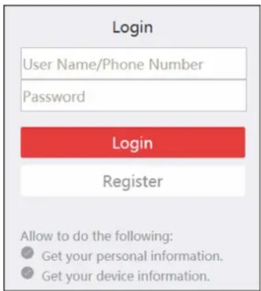
text_image
Login User Name/Phone Number Password Login Register Allow to do the following: ● Get your personal information. ● Get your device information.Figure 4-1 Register Cloud P2P Account

Note
The web browser should be Internet Explorer version 9 and later.
- Input required information, including user name, password, confirm password, and phone number/email address.

Caution
The password strength of the device can be automatically checked. We highly recommend you change the password of your own choosing (using a minimum of 8 characters, including at least
three kinds of following categories: upper case letters, lower case letters, numbers, and special characters) in order to increase the security of your product. And we recommend you reset your password regularly, especially in the high security system, resetting the password monthly or weekly can better protect your product.
Proper configuration of all passwords and other security settings is the responsibility of the installer and/or end-user.
- Click Send Message to get verification code.
The system will send verification code to your phone or email.
- Input the received verification code in the Verification Code text field.
- Click Register to finish the registration.
4.2 Log in to Cloud P2P Account
You can log in to Cloud P2P account via the client software.
Before You Start
Register a Cloud P2P account.

Note
For details, refer to Register a Cloud P2P Account.
Perform this task when you want to log in to the registered Cloud P2P account via client software.
Steps
- Enter the Deivce Management page.
- Click Device → Cloud P2P Device to enter the Welcome to Cloud P2P page.
- Click Login to enter Login page.
- Input user name/phone number, and password.
- Click Login to log into your account.
- Optional: Click Logout to log out of your account.
4.3 Device Management
You can add the Cloud P2P device to the Cloud P2P account, and delete the added device(s) from the account. You can also do remote configuration and group management to the devices of the Cloud P2P account.
4.3.1 Add Device to Cloud P2P Account
You can add the Cloud P2P device to the Cloud P2P account via two ways, i.e., adding manually or adding via online device.

Note
You can add 256 devices (1024 cameras) to one Cloud P2P account at most.
Add Online Device
You can add online Cloud P2P device(s) in the same local subnet with the PC running the client to the Cloud P2P account.
Perform this task if you need to add online device(s) to the Cloud P2P account.
Steps
- Enter the Device Management page.
- Click Device → Cloud P2P Device and log into your Cloud P2P account.
The active online devices in the same local subnet with the client software will be displayed on the Online Device area. You can click Refresh Every 60s to refresh the information of the online devices.
- Select the device(s) which support Cloud P2P service on the online device list.
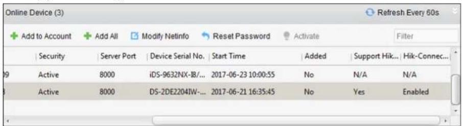
text_image
Online Device (3) + Add to Account + Add All Modify Netinfo Reset Password Activate Filter Security Server Port Device Serial No. Start Time Added Support Hik... Hik-Connec... Active 8000 iDS-9632NX-18/... 2017-06-23 10:00:55 No N/A N/A Active 8000 DS-2DE2204IW-... 2017-06-21 16:35:45 No Yes EnabledFigure 4-2 Online Device List

Note
For the inactive device, you need to create the password and enable the Cloud P2P service for it before you can add the device properly. For details, refer to Activate Devices.
- Click Add to Account to open the device adding dialog box.
-
- Input the verification code.
The verification code is created when you enabling the Cloud P2P service. For details, refer to Activate Devices.
- Click OK to add the device.
- Optional: Select device from the Device Management page and click Delete to remove the device from the Cloud P2P account.
What to do next
After adding the device to the Cloud P2P account, you should add the device by Cloud P2P if you want to add the device to the local client software. For details, refer to Add Device by Cloud P2P.
Manually Add Device
You can add Cloud P2P device to the Cloud P2P account manually by inputting the serial No. and verification code.
Perform this task if you need to add a device manually.
Steps

Note
- Only the device that supports the Cloud P2P service can be added.
-
One device can only be added to one Cloud P2P account.
-
Enter the Device Management page.
-
Click Device → Cloud P2P Device and then log into your Cloud P2P account.
-
Click Add Device to open the Add Device window.
-
Input the serial No. and verification code of the device.
Serial No.
Marked on the label of you device.
Verification Code
Created when you enabling the Cloud P2P service. For details, refer to Activate Devices.
- Click OK to add the device.
The successfully added device will be displayed on the Device Management page.
What to do next
After adding the device to the Cloud P2P account, you should add the device by Cloud P2P if you want to add the device to the client. For details, refer to Add Device by Cloud P2P.
4.3.2 Edit Camera Parameters
After adding a Cloud P2P device to the local client software, you can edit the camera parameters and set stream key.
Before You Start
Add a Cloud P2P device to the local client software.

Note
See Manually Add Device or Add Online Device for details.
Perform this task when you need to edit camera which is added to Cloud P2P account.
Steps
- Enter Device Management page.
-
Click Group tab.
-
Select camera in the resource list.
- Click Modify to pop up Modify Camera dialog.
- Edit the camera information, including name, rotate, protocol type, etc.
Rotate
Select the rotate type for the live view or playback of the camera as desired.
Stream Key
For Cloud P2P device, the stream key is the same with the verification code, which is created when you enable the Cloud P2P service.
If the live view or video file(s) of the Cloud P2P device is encrypted, you should input the stream key on the Modify Camera window before you can view the live view or video file(s) of the device.

You can set whether to encrypt the live view or video file(s) of the Cloud P2P device on the Cloud P2P mobile client software. For details, refer to the User Manual of the Cloud P2P Mobile Client Software.
- Optional: Click Copy to copy the configured parameters to other camera(s).
- Click OK to edit the camera.
Chapter 5 Group Management
The resources added should be organized into groups for convenient management, such as encoding channels, alarm inputs, alarm outputs, zones, access control points, and lane controllers. You can get the live view, play back the videofiles, and do some other operations of the device through the group.
5.1 Add Group
You can add group to organize the added device for convenient management.
Perform this task if you need to add group for managing device.
Steps
-
Click Device Management → Group to enter the group management page.
-
Click to open the Add Group dialog.
-
Set the group name.
-
Create a group name as you want in the Group Name field.
-
Check Create Group by Device Name to create the new group by the name of the selected device.
-
Click OK to add the new group to the group list.
5.2 Import Resources to Group
You can import the device resources (such as encoding channels, alarm input, alarm outputs, etc.) to the added group in a batch.
Before You Start
Add a group for managing devices. Refer to Add Group.
Perform this task if you want to import the device resources to group. Here we take importing the device's encoding channels to group as an example.
Steps
i Note
Up to 256 encoding channels can be added to one group.
- Click Device Management → Group to enter the group management page.
- Click Import.
- Click Encoding Channel tab to enter Import Encoding Channel page.
- Select the thumbnails/names of the cameras in the thumbnail/list view.

You can click or to switch the camera display mode to thumbnail view or to list view.
- Select a group from the group list.

You can click to add a new group if there is no required group in the list.
-
Import encoding channels to group.
-
Click Import to import the selected encoding channels to the selected group.
- Click Import All to import all the encoding channels to the selected group.
- Click to create a new group named as device name and directly import the corresponding encoding channels to group.
5.3 Edit Channel Parameters
After importing the channels to the group, you can edit the channel's parameters. For encoding channel, you can edit the channel name, stream type, protocol type, etc. For alarm input, zone, and other types of channels, you can edit the channel name.
Before You Start
Import the channels to group. Refer to Import Resources to Group.
Perform the following steps to edit the parameters of the channels imported to group. Here we take modifying the encoding channel's parameters as an example.
Steps

For modifying the camera(s) of Cloud P2P device, refer to Edit Camera Parameters.
- Click Device Management → Group to enter the group management page.
All the added groups are displayed on the left.
- Click Encoding Channel in the group.
The encoding channels imported to the group will display.
-
Open the Modify Camera dialog.
-
Double click the encoding channel.
-
Select the encoding channel and click Modify.
-
Edit the camera information, including the camera name, the stream type, etc.
Video Stream
Select the stream for the live view of the camera as desired
Playback Stream Type
Select the stream for the playback of the camera as desired.

The Playback Stream Type field will display if the device supports dual-stream.
Rotation Type
Select the rotate type for the live view or playback of the camera as desired.
Protocol Type
Select the transmission protocol for the camera.
Streaming Protocol
Select the protocol as RTSP or private forgetting stream when live view.

You should get stream again to take effect.
Stream Media Server
Get stream of the camera via stream media server. You can select and manage the available stream media server.
Copy to...
Copy the configured parameters to other camera(s).
Refresh
Get a new captured picture for the live view of the camera.

For video stream and protocol type, the new settings will take effect after you reopen the live view of the camera.
5. Click OK to save the new settings.

For the IP channel of NVR which supports decoding function:
- After decoding and displaying on video wall, there will be a new channel in the Encoding Channel Resources list whose protocol type is decoding on video wall.
- After closing the corresponding roaming window, the new channel will be removed from the Encoding Channel Resources list.
5.4 Remove Channel from Group
You can remove the added channels from the group.
Perform the following steps to remove the added channels from the group. Here we take encoding channel as an example.
Steps
- Click Device Management → Group to enter the group management page.
All the added groups are displayed on the left.
- Click Encoding Channel in the group.
The encoding channels imported to the group will display.
-
Select the encoding channel and click Delete to remove the camera from the group.
-
Optional: Remove all the encoding channels from the group.
1) Click Import.
All the groups and the encoding channels in the groups will display.
2) Move the mouse to the group.
3) Click ✗ near the group name to remove all the cameras from the group.
5.5 Delete Group
You can delete the group if needed.
Perform the following steps to delete the group.
Steps
-
Click Device Management → Group to enter the group management page.
-
Delete the group.
-
Select the group and click 📄.
- Move the mouse to the group and click ✗.
The selected group and the resource in it will be deleted.
Chapter 6 Live View
For the surveillance task, you can view the live video of the added network cameras, video encoders, and video intercom device on the Main View page. And some basic operations are supported, including picture capturing, manual recording, PTZ control, etc.
The following icons show different statuses of the camera.
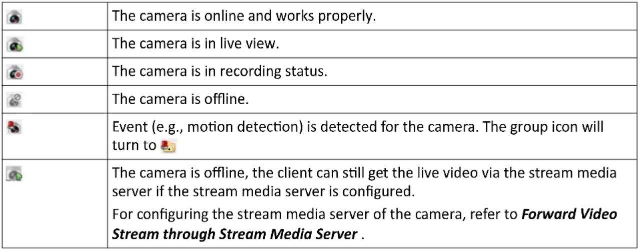 |
6.1 Start and Stop Live View
You can start the live view of one camera or all cameras in a group. You can also start the live view in default or custom view mode.
6.1.1 Start Live View for One Camera
You can start the live view of only one camera.
Before You Start
A camera group is required to be defined for live view.
Perform this task if you want to start the live view of one camera.
Steps
- Open the Main View page.
- Optional: Click in live view toolbar to select the window division mode for live view.
- Optional: Click Original Results to set the view scale of the live view window. You can set it as Full Screen, 4:3, 16:9, or Original Resolution.

Note
You can also set the view scale for both live view and playback window in System Configuration. For details, refer to Set Image Parameters.
-
Do one of the following operations to start the live view of one camera.
-
Drag a camera in the group from camera list to a display window to start the live view.
- Double-click the camera name after selecting a display window to start the live view.

Note
For Cloud P2P device, if the live view or video file(s) of its camera(s) is encrypted, you should input the stream key.
- Optional: Drag the video of the camera in live view to another window to change the display window for live view.
- Optional: Right click on the camera name in the camera list to switch the stream type according to actual needs.

Note
You can click All Stream Types to select the frequently used stream types to display on the right-click menu.
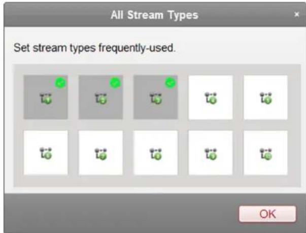
text_image
All Stream Types Set stream types frequently-used. OKFigure 6-1 Select Frequently Used Stream Types
6.1.2 Start Live View for Camera Group
You can start the live view for all cameras in one group synchronously.
Before You Start
A camera group is required to be defined for live view.
Perform this task when you want to start live view for camera group.
Steps
-
Open the Main View page.
-
Optional: Click Original Resolu to set the view scale of the live view window. You can set it as Full Screen, 4:3, 16:9, or Original Resolution.

Note
You can also set the view scale for both live view and playback window in System Configuration. For details, refer to Set Image Parameters.
-
Perform one of the following operations to start the live view of all cameras in a group.
-
Drag a camera group from camera list to the display window to start the live view.
- Double-click the group name to start the live view.

Note
The display window number is self-adaptive to the camera number of the group.
- Optional: Right click on the group name in the camera list to switch the stream type for the cameras in the group.

Note
Before switching to the sixth, seventh, eighth, ninth, and tenth stream, you should set these stream type in the device's web configuration page. For details, refer to the user manual of the device.
6.1.3 Start Live View in Default View Mode
The video of the added cameras can display in different view modes. Four frequently-used default view modes are selectable: 1-Window, 4-Windows, 9-Windows, and 16-Windows.
Perform this task when you want to start live view in default view mode.
Steps
- Open the Main View page.
- Click ✦ to expand the default view list in the View panel.
- Select the default view mode.
The video of the added cameras displays in a sequence in the selected view.
- Optional: Click Original Resolution to set the view scale of the live view window. You can set it as Full Screen, 4:3, 16:9, or Original Resolution.

Note
You can also set the view scale for both live view and playback window in System Configuration. For details, refer to Set Image Parameters.
- Optional: Perform the following operation(s) after starting live view in default mode.
| Start Instant Playback | Move the cursor over the view and click to start the instant playback of the view, seeInstant Playbackfor details. |
| Start Auto-Switch | Move the cursor over the view and click to start switching automatically of the view, see details inAuto-Switch in Live View. |
6.1.4 Start Live View in Custom View Mode
A view is a window division with cameras configured to each window; View mode enables you to save the window division and the correspondence between cameras and windows as favorite to quickly access the related cameras later. For example, you can link camera 1, camera 2, and camera 3 located in your office to display windows and save them as a view called office. Besides the pre-defined default views, you can customize views for further operations.
Steps
-
Open the Main View page.
-
Optional: Click Original Resolution to set the view scale of the live view window. You can set it as Full Screen, 4:3, 16:9, or Original Resolution.

You can also set the view scale for both live view and playback window in System Configuration. For details, refer to Set Image Parameters.
- Customize a view.
1) Click + in the View panel to create a new view.
2) Enter a view name in the View Name field and click Add.
3) Click in the live view toolbar to set window division mode for the new view.

By default, the new view is in 4-window division.
4) Start live view for specified camera(s) in specified window(s) according to actual needs.
5) Click to directly save the view.
- Start live view of the cameras in the custom view.
1) Click + to expand the custom view list in the View panel.
2) Click a custom view to start live view.
The video of the added cameras in the selected view displays.
3) Optional: Move the cursor over the view and click 🔍 to start instant playback of the view.
6.1.5 Stop Live View
After starting the live view, you can stop it as desired.
Before You Start
Start the live view.
Perform this task when you want to stop the live view.
Steps
-
Select a live view display window on Main View page.
-
Perform one of the following operations to stop the live view.
-
Move the cursor over the display window and click ✗ appeared at the upper-right corner to stop the live view of this display window.
- Right-click on the display window to open right-click menu and click Stop Live View on the menu to stop live view.
- Click ■ in live view toolbar to stop all the live view.
6.2 Auto-Switch in Live View
You can auto-switch cameras or views in live view.
When auto-switching in live view, three modes are available:
• Auto-Switch All Cameras in Default View
• Auto-Switch Cameras in a Group
• Auto-Switch Custom Views
6.2.1 Auto-Switch Cameras in a Group
The video stream of the cameras from the same group can switch automatically in a selected display window.
Perform this task when you need to auto-switch cameras in a group.
Steps
- Open the Main View page.
- Select a display window for auto-switch.
- Click - in the toolbar to select or customize the switching interval.
- Select a group and click on the group node.
The cameras in the selected group starts auto-switch in the display window.

The audio is off by default after auto-switch starts.
- Optional: Perform the following operation(s) after starting auto-switching cameras in a group.
Pause/Resume Auto-Switch
Click ☑ to pause/resume auto-switching cameras in a group.
View Previous/Next Video
Click ↙ to view the live video of previous or next camera.
6.2.2 Auto-Switch All Cameras in Default View
The video of all the cameras in the camera list can switch automatically in the selected default view.
Perform this task when you need to auto-switch all cameras in default view.
Steps
- Open the Main View page.
- Click - in the toolbar and select or customize the switching interval.
- Select a default view to click on the selected view node.
All cameras in the camera list start auto-switching in the selected default view.
- Optional: Perform the following operation(s) after starting auto-switching all cameras in the default view.
Pause/Resume Auto-Switch
Click /to/pause/resume auto-switching all cameras in default view.
View Previous/Next Video
Click ✅ to view the live video of previous or next camera.
6.2.3 Auto-Switch Custom Views
The configured custom views can switch one by one automatically.
Perform this task when you need to auto-switch custom views.
Steps
- Open the Main View page.
- Click - in the toolbar and select the switching interval.
- Click on the Custom View node.
All configured custom views starts auto-switching.
- Optional: Perform the following operation(s) after starting auto-switching custom views.
Pause/Resume Auto-Switch
Click / to pause/resume auto-switching custom views.
View Previous/Next Video Click / to view the live video of previous or next camera.
6.3 PTZ Control
The software provides PTZ control for cameras with pan/tilt/zoom functionality. During the PTZ control, you can set preset, patrol, and pattern, and you can also open a new window for controlling the PTZ.

Note
Cloud P2P device only supports the PTZ movement to the directions of up, down, left, and right.
The following icons are available on the PTZ control panel.
| Icon Name | Description | |
| Manual Tracking For speed dome | with auto-tracking function, enable the auto-tracking (via right-click menu) for it and click the icon to manually track the target by clicking on the video. | |
| Menu For analog speed dome, | click the icon to display its local menu. For detailed operation of the menu, refer to user manual of the speed dome. | |
| One-Touch Patrol For speed dome | with one-touch patrol function, click the icon and the speed dome starts patrol from the predefined preset No.1 to preset No.32 in order after a period of inactivity (park time). For setting the park time, refer to user manual of the speed dome. | |
| One-Touch Park For the speed dome | with one-touch park function, click the icon and the speed dome saves the current view to the preset No.32. The device starts to park at preset No. 32 automatically after a period of inactivity (park time). For setting the park time, refer to user manual of the speed dome. | |
| Regional Exposure For the speed dome | dome, click the icon and draw a rectangle on the image to optimize the exposure effect in this region. | |
| Regional Focus For the speed dome | , click the icon and draw a rectangle on the image to optimize the focus effect in this region. |
6.3.1 Configure Preset
A preset is a predefined image position which contains information of pan, tilt, focus and other parameters.
Perform this task when you need to add a preset for the PTZ camera.
Steps
- Open the Main View page and start the live view of the PTZ camera.
-
Click ▲ to expand the PTZ Control panel.
-
Click Preset to enter the PTZ preset configuration panel.
- Click the direction buttons and other buttons on the PTZ control panel to steer the camera to the desired view.
- Select a PTZ preset number from the preset list and click 📋 to open a dialog.
- Input the name of the preset in the dialog.
- Click OK.
- Optional: Perform the following operation(s) after setting the preset
Call Preset
Double-click the configured preset in the list, or select the preset and click to call the preset. You can also press the number key (e.g., 4) on keyboard to call the preset 1 to 9, and press [, number keys (e.g., 124), and ] on keyboard to call the other preset.
Edit Preset
Select the configured preset from the list and click 📋 to edit it.
Delete
Select the configured preset from the list and click ✗ to delete it.
Preset
6.3.2 Configure Pattern
A pattern is a memorized, repeating series of pan, tilt, zoom, and preset functions.
Perform this task when you need to add a pattern for the PTZ camera.
Steps
i Note
For Cloud P2P device, the pattern function is not supported.
- Open the Main View page and start the live view of the PTZ camera.
- Click to expand the PTZ Control panel.
- Click Pattern to enter the PTZ pattern configuration panel.
- Click to start the recording of this pattern path.
- Use the direction buttons to control the PTZ movement.
- Click to stop recording and save the recorded pattern.
- Optional: Perform the following operation(s) after setting the pattern.
Call PatternClick to call the pattern.
Stop Calling Pattern
Click to stop calling the pattern.
Delete Pattern
Select one pattern and click ✗ to delete the pattern.
Delete All Patterns
Click 📄 to delete all patterns.
6.3.3 Configure Patrol
A patrol is a scanning track specified by a group of user-defined presets, with the scanning speed between two presets and the dwell time at the preset separately programmable.
Before You Start
Add two or more presets for one PTZ camera.
Perform this task when you need to add a patrol for the PTZ camera.
Steps

Note
For Cloud P2P device, the patrol function is not supported.
- Open the Main View page and start the live view of PTZ camera.
- Click to expand the PTZ Control panel.
- Click Patrol to enter the PTZ patrol configuration panel.
- Select a path No. from the drop-down list.
- Click + to open Add Patrol No. dialog.
- Set the dwell time and patrol speed for the preset in the dialog.
- Click OK.
- Repeat step 5, 6, and 7 to add other presets to the patrol.
- Optional: Perform the following operation(s) after setting the patrol.
Call Patrol
Click to call the patrol.
Stop Calling Patrol Click to stop calling the patrol.
Edit Preset in Patrol Select a preset in the patrol path and click to edit the preset.
Remove Preset from Patrol
Select a preset in the patrol path and click to remove the preset from the patrol.
6.4 Customize Window Division
The client software provides multiple kinds of predefined window divisions. You can also set custom the window division as desired.
Perform this task when you need to customize the window division.
Steps

Note
Up to 5 window divisions can be customized.
- Open the Main View or Remote Playback page.
-
Click on the live view or playback toolbar.
-
Select Edit to open the custom window division page.
-
Click Add to open the Add Custom Window Division dialog.
-
Set a name for the new window division as desired and click OK.
-
Select the window division as 3 × 3 , 4 × 4 , 5 × 5 , or 6 × 6 .

For remote playback, up to 16 windows can be played at the same time, so the custom window division with more than 16 windows is invalid.
-
Optional: Drag your mouse to select the adjacent windows, and click Joint to joint them as a whole window.
-
Click Save.
What to do next
Click ✗ to go back to the Main View or Remote Playback page.
6.5 Manually Record and Capture
During live view, you can record videos and capture pictures manually, and then view the recorded video files and captured pictures in the local PC.
6.5.1 Manually Record Video
Manual recording function allows to record the live video on the Main View page manually, and you can store the video files in the local PC.
Perform this task when you need to record videos manually.
Steps

The manual recording is not supported by the Cloud P2P device during live view.
-
Open the Main View page.
-
Start the live view
-
Perform one of the following operations to start manual recording.
-
Move the cursor to the display window in live view to show the toolbar and click 🔑 on the toolbar.
- Right-click on the display window and click Start Recording on the right-click menu.
The icon ○ turns to 📄 An indicator appears in the upper-right corner of the display window.
- Click to stop the manual recording.
The recorded video file is automatically saved to the local PC, and a small window with the saving path information appears in the lower-right corner of desktop.

Note
The saving path of the recorded video files can be set on the System Configuration page. See Set File Saving Path for details.
6.5.2 View Local Videos
You can view the recorded video files stored in your local PC.
Before You Start
Record the live video.
Perform this task when you need to view the local video files.
Steps
- Click File → Open Video File in the upper-left corner to open the Video Files page.
- Select the camera to be searched from the Camera Group list.
- Click 📋 to specify the start time and end time for the search.
- Click Search.
The video files recorded between the start time and end time displays in thumbnail format on the page.
- Optional: Perform the following operation(s) after the search.
Delete Video
Select the video file, and click Delete to delete the video file.
File
Send Email
Select the video file, and click Send Email to send an email notification with the selected video file attached.

Note
To send an email notification, the email settings need to be configured before proceeding. For details, refer to Set Email Parameters.
Save Local Video
Select the video file, and click Save as to save a new copy of the video file.
Playback Double-click the video file to start the local playback.
6.5.3 Capture Pictures
You can capture pictures during the live view.
Perform this task when you need to capture pictures during the live view.
Steps
-
Open Main View page and start the live view of a camera.
-
Perform one of the following operations to capture pictures.
-
Move the cursor to the display window in live view to show the toolbar and click on the toolbar.
- Right-click the display window and click Capture on the right-click menu.
The captured picture is automatically saved to the local PC, and a small window with the picture preview and saving path information appears in the lower-right corner of desktop.

The saving path of the captured pictures can be set on the System Configuration page. For details, refer to Set File Saving Path.
6.5.4 View Captured Pictures
The pictures captured in the live view are stored in the PC running the software. You can view the captured pictures if needed.
Before You Start
Capture pictures in the live view.
Perform this task when you need to view the captured pictures.
Steps
- Click File → Open Image File in the upper-left corner to open the Captured Images page.
- Select the camera to be searched from the Camera Group list.
- Click 📄 to specify the start time and end time for the search.
- Click Search.
The pictures captured between the start time and end time display in thumbnail format on the page.
- Optional: Perform the following operation(s) after the search.
Enlarge Picture Double-click the picture thumbnail to enlarge it for a better view.
Print Picture Select the captured picture, and click Print to print the selected picture.
Delete Picture Select the captured picture, and click Delete to delete the selected picture.
Send Email Select the captured picture, and click Send Email to send an email notification with the selected picture attached.
Save Picture Select the captured picture, and click Save as to save a new copy of the selected picture.
6.6 Instant Playback
Instant playback shows a piece of the video which is remarkable, or which is unclear on the first sight. So you can play the video files instantly on the Main View page and get an immediate review if needed.
Before You Start
Record the video files and store them on the storage devices, such as the SD/SDHC cards and HDDs on the DVRs, NVRs, network cameras, etc., or on the storage servers.
Perform this task when you need to start the instant playback.
Steps
-
Open Main View page and start the live view.
-
Perform one of the following operations to show the pre-play durations' list of instant playback.
-
Move the cursor to the display window to show the toolbar and click
- Right-click the display window and select Switch to Instant Playback on the right-click menu.
- Move the cursor to default view or custom view node on the View panel and click 🔔.
The list with pre-play durations of 30s, 1 min, 3 min, 5 min, 8 min, and 10 min displays.
- Select a time period from the appeared list to start the instant playback.
Example
If you select 3 min, and the current time of the live view is 09:30:00, then the instant playback will start from 09:27:00.
During the instant playback, an indicator 📋 appears in the upper-right corner of the display window.
- Optional: Click 📋 again to stop the instant playback and go back for the live view.
6.7 Live View for Fisheye Camera
For fisheye cameras, you can start the live view in fisheye mode, set presets and patrols, and perform PTZ control.
6.7.1 Perform Live View in Fisheye Mode
You can play the live videos of the camera in fisheye expansion mode.
Perform this task when you need to start live view in fisheye mode for fisheye camera.
Steps
- Open the Main View page and start the live view of fisheye camera.
- Right-click on the video and select Fisheye Expansion to enter the Fisheye Expansion window.
- Select the mounting type of the fisheye camera according to the actual mounting position.
- Select the expanding mode for live view as desired.
Fisheye
In the Fisheye view mode, the whole wide-angle view of the camera is displayed. This view mode is called Fisheye because it approximates the vision of a fish's convex eye. The lens produce curvilinear images of a large area, while distort the perspective and angles of objects in the image.
Panorama
In the Panorama view mode, the distorted fisheye image is transformed to normal perspective image by some calibration methods.
PTZ
The PTZ view is the close-up view of some defined area in the Fisheye view or Panorama view, and it supports the electronic PTZ function, which is also called e-PTZ.

Each PTZ view is marked on the Fisheye view and Panorama view with a specific navigation box. You can drag the navigation box on the Fisheye view or Panorama view to adjust the PTZ view, or drag the PTZ view to adjust the view to the desired angle.
Half Sphere
In the half sphere mode, you can drag the image and rotate it by the diameter, in order to adjust the view to the desired angle.
- Optional: Perform the following operation(s) after starting live view in fisheye mode.
| Capture | Right-click on the window and select Capture to capture the picture in the live view process. |
| Enter Full Screen | Right-click on a playing window and switch the selected window to full-screen mode. |
6.7.2 PTZ Control in Fisheye Mode
In fisheye mode, you can control the PTZ to adjust the PTZ window.

The PTZ panel varies according to different devices.
The following functions are available on the PTZ control panel.
- Select a PTZ window, and click the direction buttons to adjust view angle. Or drag the No. label in the fisheye or panorama window to change the view angle of the PTZ window.
- Select a PTZ window, click to start auto-scan, and click it again to stop auto-scan.
- Drag the slider on - + to adjust the speed for PTZ movement.
- Click or, or scroll the mouse wheel to zoom in or zoom out the selected PTZ window.
Configure Preset
In fisheye mode, you can configure the preset which is a user-defined monitor position/point and simply call the preset No. to change the monitor scene to the defined position.
Perform this task when you need to configure preset in fisheye mode.
Steps

Note
Only the specific fisheye cameras support configuring the preset, and up to 256 presets can be configured in fisheye mode.
- Open Main View page and start the live view of fisheye camera.
- Right-click on the video and select Fisheye Expansion to enter the Fisheye Expansion window.
- Click Preset tab to enter the preset configuration panel.
- Select a PTZ window and adjust the scene to the place you want to mark as a preset.
- Click ☐ to open Add Preset window.
- Input the preset name.
- Click OK.
- Optional: Perform the following operation(s) after configuring the preset.
Call Preset
Select the preset and click to call the configured preset.
Delete Preset
Select the preset and click ✗ to delete the configured preset.
Configure Patrol
In fisheye mode, you can configure the patrol, which is a scanning track specified by a group of user-defined presets, with the scanning speed between two presets and the dwell time at the preset separately programmable.
Before You Start
Configure two or more presets.
Perform this task when you need to configure the patrol in fisheye mode.
Steps

Note
Only the specific fisheye cameras support configuring the patrol, and up to 32 patrols can be configured in fisheye mode.
- Open Main View page and start the live view of fisheye camera.
- Right-click on the video and select Fisheye Expansion to enter the Fisheye Expansion window.
- Click Patrol tab to enter the patrol configuration panel.
-
Select a path No. from the drop-down list.
-
Click + to open Add Patrol No. window.
-
Set the dwell time for the preset.

The dwell time ranges from 1s to 120s.
- Click OK.
- Repeat step 5, 6, and 7 to add other presets to the patrol.
- Optional: Perform the following operation(s) after configuring the patrol.
Edit Preset in Patrol Select a preset in the patrol path and click to edit the preset.
Remove Preset from Patrol
Select a preset in the patrol path and click to remove the preset from the patrol.
Call Patrol Click to call the patrol.
Stop Calling Patrol Click to stop calling the patrol.
6.8 Perform Master-Slave Linkage
The box or bullet camera which supports master-slave tracking function can locate or track the target according to your demand.
i Note
- This function in only supported by the specific box or bullet camera.
- A speed dome with the auto-tracking function is required to be installed near the box or bullet camera.
6.8.1 Configure Master-Slave Tracking Rule
Before performing master-slave tracking during live view, you should configure the master-slave tracking rules for the box or bullet camera, including setting VCA detection rule, linking to a speed dome, and calibrating camera and speed dome.
Set Intrusion Detection Rule
You should set the VCA detection rule for the bullet or box camera, and when the VCA event is triggered, the client can trigger speed dome to track the target. Here we take intrusion detection as an example.
Steps
- Open Device Management page and select a box or bullet camera.
-
Click → Advanced Configuration → VCA Config → Rule → Rule Settings to enter rule settings page.
-
Click Add in Rule List panel to add a rule.
- Select Intrusion as the event type.
- Click ☐ to draw a detection region on the live video.
- Click Save.
Link Speed Dome
When configuring the master-slave tracking for the box or bullet camera, you can link the camera to a speed dome and set the PTZ position for the speed dome for tracking.
Perform this task to link the box or bullet camera to a speed dome for master-slave tracking.
Steps
- Open Device Management page and select a box or bullet camera.
- Click → Advanced Configuration → Master-Slave Tracking to enter master-slave tracking settings page.
- Click Login on the display window to open the speed dome login window.
- Input the speed dome's IP address, port No., user name, and password.
- Click Login to log in to the speed dome.
- Click PTZ and use the direction arrows to adjust the speed dome to a horizontal position.
What to do next
Calibrate the box or bullet camera and the linked speed dome, see Calibrate Camera and Speed Dome Automatically or Calibrate Camera and Speed Dome Manually for details.
Calibrate Camera and Speed Dome Automatically
When setting the bullet or box camera's master-slave tracking rule, you should calibrate the camera and the speed dome. Two calibration modes, including auto and manual, are available, here we introduce the auto calibration.
Before You Start
Link the camera to a speed dome, see Link Speed Dome for details.
Steps
- Open Device Management page and select a box or bullet camera.
- Click → Advanced Configuration → Master-Slave Tracking to enter master-slave tracking settings page.
- Select the calibration mode as Auto Calibrating in the lower-right corner of Calibration panel.
- Move and zoom in/out the view of speed dome to make sure the live views of dome and camera are mostly same.
- Click Save.
Calibrate Camera and Speed Dome Manually
When setting the bullet or box camera's master-slave tracking rule, you should calibrate the camera and the speed dome. Two calibration modes, including auto and manual, are available, here we introduce the manual calibration.
Before You Start
Link the camera to a speed dome. See Link Speed Dome for details.
Steps
- Open Device Management page and select a box or bullet camera.
- Click → Advanced Configuration → Master-Slave Tracking to enter master-slave tracking settings page.
- Select the calibration mode as Manual Calibrating in the lower-right corner of Calibration panel.
- Select site No. 1 from the list and click + .
A blue cross appears in the center of the live view page, and the digital zoom view of the selected site appears on the right.
- Repeat step 4 to add other manual calibration sites.
- Adjust the distances among the four calibration sites evenly in the live view page.
- Select the calibration site No. 1.
The digital zoom view of site No. 1 appears at the right.
- Move and zoom in or out the view of speed dome to make sure the live views of speed dome and the digital zoom view of selected site are mostly same.
- Click ✉ to save the current site position information.
- Repeat step 7, 8, and 9 to set other sites' position.
- Click Save.
6.8.2 Enable Master-Slave Tracking
During live view, you can enable the master-slave tracking to locate or track the target appeared in the view of bullet or box camera with a speed dome.
Before You Start
Configure the master-slave tracking rules for the box or bullet camera.
Perform this task when you need to enable the master-slave tracking for box or bullet camera.
Steps
- Enter the Main View page and start the live view of box or bullet camera.
- Right-click on the live view window and click Enable Master-Slave Tracking.
When the configured VCA rule is triggered by target, the linked speed dome performs the automatic master-slave tracking and the target frame turns from green into red.
6.9 Live View for Thermal Camera
For thermal camera, you can view the fire source information and temperature during live view. You can also measure the temperature manually to get temperature information in the live view image.
6.9.1 View Fire Source Information during Live View
During the live view, you can view the detected fire source information.
Before You Start
Configure the alarm rules for the thermal device, see the user manual of the device for details. Perform this task when you need to view the fire source information during live view.
Steps
- Enter Main View page and start the live view of a thermal camera.

Note
For starting and stopping live view, refer to Start Live View for One Camera and Stop Live View.
- Right-click on the live view image and select File Source Information in the right-click menu to show the list of information types.
- Select a information type in the list to display the information.
Fire Source Region
The region in which the temperature is higher than the configured alarm threshold.
Maximum Temperature Region
Mark the region in which the temperature is highest in the fire source region. It is marked in green.
Fire Source Target
Display the target location information.
text_image
1Figure 6-2 Fire Source Information on Live View Image
6.9.2 Show Temperature Information on Live View Image
You can show or hide the real-time temperature information of the monitoring scene when viewing the live video.
Before You Start
- Switch the device VCA source type as Temperature Measurement + Behavior Analysis.
- Enable the device temperature measurement function and set the temperature measurement rules, see the user manual of the device for details.
Perform this task when you need to show the temperature information on the live view image.
Steps
- Enter Main View page and start the live view of a thermal camera.

For starting and stopping live view, refer to Start Live View for One Camera and Stop Live View.
- Adjust the scene to the area configured with temperature measurement rule.
- Right-click on the live view image and select Show Temperature Information in the right-click menu.
The temperature displays on the live view image. - Click on the image to view the detailed temperature information.
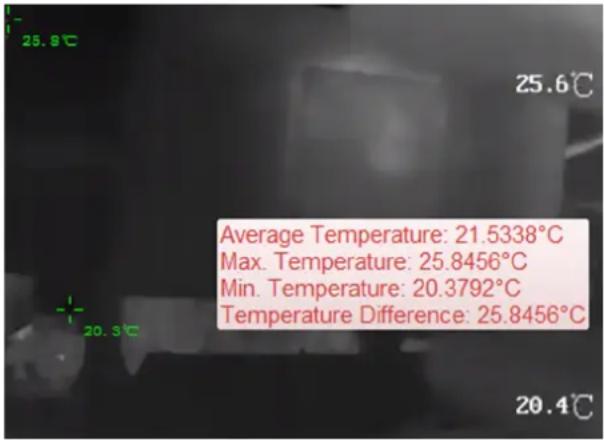
text_image
25.8°C 25.6°C Average Temperature: 21.5338°C Max. Temperature: 25.8456°C Min. Temperature: 20.3792°C Temperature Difference: 25.8456°C 20.3°C 20.4°CFigure 6-3 Temperature Information on Live View Image
- Optional: Right-click on the live view image and select Hide Temperature Information to hide the temperature information.
6.9.3 Manually Measure Temperature on Points
During the live view of thermal camera, you can draw points on the live view image to measure the temperature on different points.
Perform this task when you need to measure temperature on points manually.
Steps
- Enter Main View page and start the live view of a thermal camera.

For starting and stopping live view, refer to Start Live View for One Camera and Stop Live View.
-
Perform one of the following operations to select the temperature measurement type.
-
Right-click on the live view image and select Manual Temperature Measurement → By Point.
-
Click 📄 on the live view toolbar and select By Point.
-
Click on the live view image to draw the points.
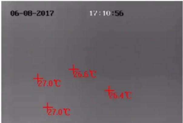
text_image
06-08-2017 17:10:56 +27.0℃ +26.6℃ +26.4℃ +27.0℃Figure 6-4 Temperature Measurement on Points
The temperatures of the configured points show on the image beside the points.
- Optional: Perform the following operation(s) after measuring temperature on points manually.
Delete Point
Click Cancel and click a drawn point on the live view image to delete.
Hide Temperature
Right-click on the live view image and select Disable Manual
Temperature Display on the right-click menu.
6.10 More Functions
There are some more functions supported in the live view, including auxiliary screen preview, digital zoom, channel-zero, two-way audio, camera status, and synchronization.
Auxiliary Screen Preview
Display the live video on different auxiliary screens for the convenient preview of multiple monitoring scenes.

Note
Up to 3 auxiliary screens are supported.
Digital Zoom
Drag the mouse to draw a rectangle area in the lower-right/upper-left direction to zoom in or out the drawn area. Or use the mouse wheel to zoom in or out the view in digital zoom mode.
Channel-Zero
For the channel-zero of the device, hold the Ctrl key and double-click to display the specific channel. Hold the Ctrl key and double-click again to restore.
Two-Way Audio
Two-way audio function enables the voice talk of the camera. You can get not only the live video but also the real-time audio from the camera. If the device has multiple two-way audio channels, you can select a channel to start two-way audio.

Note
- The two-way audio can be used for only one camera at one time.
- Cloud P2P device doesn't support selecting channel during two-way audio.
Camera Status
The camera status, such as recording status, signal status, connection number, etc., can be detected and displayed for checking. The status information refreshes every 10 seconds.
Synchronization
The synchronization function provides a way to synchronize the device clock with the PC which runs the client software.
Chapter 7 Remote Storage Configuration
The video files and captured pictures can be stored on the HDDs, Net HDDs, or SD/SDHC cards on the local device, or on the storage server connected.
7.1 Store Picture and Video on DVR, NVR, or Network Camera
Some local devices, including the DVRs, NVRs, and Network Cameras, provide storage devices such as the HDDs, Net HDDs and SD/SDHC cards for video and picture files. You can set a recording schedule or capture schedule for the channels of the local devices.
Before You Start
The newly installed storage devices should be formatted. Go to the remote configuration page of the device, click Storage → General, select the HDD or SD/SDHC card, and click Format to initialize the selected storage device.
Perform this task when you need to store the picture and video files on the encoding device such as DVR, NVR, or network camera.
Steps

Note
The pictures captured through the capture schedule are stored on the local device and can be searched on the remote configuration page of the device.
- Open the Storage Schedule page.
- Select the camera in the Camera Group list.
- Check Recording Schedule or Capture Schedule under Storage of Encoding Server to enable device local recording or capture.

text_image
Storage of Encoding Se... ✓ Recording Schedule: Template 01 ✓ Edit Advanced Settings ✓ Capture Schedule: Template 01 ✓ Edit Advanced SettingsFigure 7-1 Enable Local Recording or Capture
- Select the recording or capture schedule template from the drop-down list.
All-day Template
All-day continuous recording.
Weekday Template
Working-hours continuous recording from 8:00 AM to 8:00 PM.
Event Template
All-day event triggered recording.
Template 01 to 08
Fixed templates for specific schedules. You can edit the templates if needed.
Custom
Customize a template as you want.

If you need to edit or customize the template, refer to Configure Recording Schedule Template or Configure Capture Schedule Template.
- Click Advanced Settings of Recording Schedule to set the recording advanced parameters.

The displayed items vary according to the devices.
Pre-record
Normally used for the event triggered record, when you want to record before the event happens.
Post-record
After the event finished, the video can also be recorded for a certain time.
Keep Video Files for
The time for keeping the video files in the storage device, once exceeded, the files will be deleted. The files will be saved permanently if the value is set as 0.
Redundant Recording
Save the video files not only in the R/W HDD but also in the redundant HDD.
Record Audio
Record the video files with audio or not.
Video Stream
Select the stream type for the recording.

For specific type of devices, you can select Dual-Stream for recording both main stream and sub-stream of the camera. In this mode, you can switch the stream type during remote playback. Refer to Normal Playback for stream switch during playback.
- Click Advanced Settings of Capture Schedule to set the capture advanced parameters.
Resolution
Select the resolution for the continuous or event captured pictures.
Picture Quality
Set the quality for the continuous or event captured pictures.
Interval
Select the interval which refers to the time period between two capturing actions.
Captured Picture Number
Set the picture number for event capture.
- Optional: Click Copy to... to copy the recording schedule settings to other channels.
- Click Save to save the settings.
7.2 Store Picture and Video on Storage Device
You can store the video files and pictures of the added encoding devices on storage device.
You can add storage device to the client for storing the video files and pictures of the added encoding devices and you can search the files for remote playback. The storage device can be Guarding Vision Storage Server, CVR (Center Video Recorder), or other NVR.
Here we take the settings of Guarding Vision Storage Server as an example.

Note
The Guarding Vision Storage Server application software needs to be installed and it is packed in the client installation package. After running the installation package, select Storage Server to enable the installation of Guarding Vision Storage Server.
7.2.1 Activate Storage Server
If it is the first running the Guarding Vision Storage Server, you are required to active the storage server.
Perform this task when you need to activate storage server.
Steps
- Click on the desktop to run the Guarding Vision Storage Server.

Note
- If the storage server port (value: 8000) is occupied by other service, a dialog will pop up. You should change the port No. to other value to ensure the proper running of the storage server.
-
You can also record the video files on the Guarding Vision Storage Server installed on another PC.
-
Enter the New Password and Confirm Password.

Caution
The password strength of the device can be automatically checked. We highly recommend you change the password of your own choosing (using a minimum of 8 characters, including at least three kinds of following categories: upper case letters, lower case letters, numbers, and special characters) in order to increase the security of your product. And we recommend you reset your password regularly, especially in the high security system, resetting the password monthly or weekly can better protect your product.
Proper configuration of all passwords and other security settings is the responsibility of the installer and/or end-user.
- Click OK to change the password.
After changing the password, the storage server will run automatically.
7.2.2 Add Storage Server to Client
You can add storage server to the client for storing the video files and pictures of the added encoding devices.
Perform this task when you need to add storage server.
Steps
- Open the Device Management page.
- Click Device.
- Click Device to display the device list.
-
Add Guarding Vision Storage Server.
-
You can add online storage server. For details, refer to Add Single Online Device.
- You can add storage server via IP address or domain name. For details, refer to Add Device by IP Address or Domain Name
7.2.3 Format Storage Server's HDD
You should format the HDDs of the storage server for the video file and picture storage.
Perform this task to format storage server's HDD.
Steps

Note
Formatting the HDDs is to pre-allocate the disk space for storage and the original data of the formatted HDDs will not be deleted.
- Open the Device Management page.
- Click Device.
-
Select the added storage server from the list.
-
Click Remote Configuration.
- Click Storage → General to enter the HDD Formatting window.
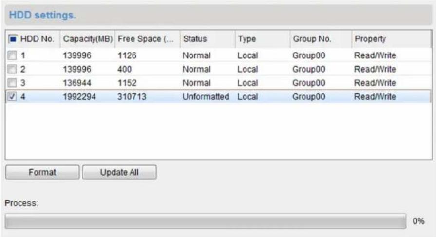
text_image
HDD settings. ■ HDD No. Capacity(MB) Free Space (... Status Type Group No. Property □ 1 139996 1126 Normal Local Group00 Read/Write □ 2 139996 400 Normal Local Group00 Read/Write □ 3 136944 1152 Normal Local Group00 Read/Write ✓ 4 1992294 310713 Unformatted Local Group00 Read/Write Format Update All Process: 0%Figure 7-2 HDD Formatting
- Select the HDD from the list and click Format.
You can check the formatting process from the process bar and the status of the formatted HDD changes from Unformatted to Normal Status.
7.2.4 Configure Storage Settings
When the storage server is available, you can set the recording schedule or capture schedule for the cameras.
Before You Start
The newly installed storage devices need to be formatted.
Perform this task when you need to configure storage settings.
Steps
- Click Storage Schedule on the control panel to open the Storage Schedule page.
- Select the camera in the Camera Group list.
- Select a storage server from the Storage Server drop-down list.

You can click Storage Server Management to add, edit or delete the storage server.
- Check Recording Schedule or Picture Storage to enable storing the video files or alarm pictures of the camera when event occurs.
- Optional: For the network cameras with the function of heat map or people counting, check Additional Information Storage and click VCA Config to set the VCA rule for the camera.

Note
For detailed configuration about setting the VCA rule, refer to user manual of the camera.
You can upload the heat map, people counting data, and road traffic data to the storage server.
- Select the schedule template for recording or capture from the drop-down list.

Note
If you need to edit or customize the template, refer to Configure Recording Schedule Template or Configure Capture Schedule Template.
- Optional: For Recording Schedule, click Advanced Settings to set the pre-record time, post-record time, video stream, and other parameters.

Note
The Guarding Vision Storage Server only supports main-stream.
- Click Set Quota to set the corresponding quota ratio for record, picture, and additional information.
Example
If you set Record Quota as 60%, up to 60% of the storage space can be used for storing the video files.
- Click Save to save the settings.
7.3 Configure Recording Schedule Template
You can edit the recording schedule template, or customize a recording schedule template.
Perform this task if you need to configure the recording schedule template.
Steps
-
Enter the Storage Schedule module.
-
Open the template settings window.
-
Select Template 01 to Template 08 from the dropdown list and click Edit.
-
Select Customfrom the drop-down list.
-
Drag on the time-line to set the time periods for the selected template when the cursor turns to
Continuous
Normal and continuous recording. The schedule time bar is marked with .
Event Recording
The recording is triggered by event. The schedule time bar is marked with .
Command
The recording triggered by command. The schedule time bar is marked with .

Command triggered recordding is only available for the ATM transactions when the ATM DVR is added to the client.

Up to 8 time periods can be set for each day in the recording schedule.
- Optional: After setting the time periods, you can do one or more of the following:
Move Drag a time period to move it when the cursors turns to .

Lengthen or Shorten Select a time period and then lengthen or shorten it when the cursor turns to
Delete Select the configured schedule time period and click ✗ to delete it.
Delete All Click to delete all the configured time periods.
Copy to Select one date and click 📋 to copy the date's time period settings to the other dates.
-
Optional: For template 01 to 08, you can edit the template name as you want.
-
Click OK to save the settings.

If you select Custom to customize a template, you can click Save as Schedule Template, and then the custom template can be saved as template 01 to 08.
7.4 Configure Capture Schedule Template
You can edit the capture schedule template, or customize a capture schedule template.
Perform this task if you need to configure the capture schedule template.
Steps
-
Enter the Storage Schedule module.
-
Open the template settings window.
-
Select Template 01 to Template 08 from the dropdown list and click Edit.
-
Select Custom from the dropdown list.
-
Drag on the time-line to set time periods for the selected template when the cursor turns to √.
Continuous Capture
Normal and continuous capture. The schedule time bar is marked with
Event Capture
The capture is triggered by event. The schedule time bar is marked with .
- Optional: After setting the time period, you can do one or more of the followings
Move When the cursor turns to , you can move the time period you just edited. You can also edit the displayed time point to set the accurate time period.
Lengthen or Shorten When the cursor turns to 3, you can lengthen or shorten the selected time period.
Delete Select a time period and click to delete it.
Delete All Click 📋 to delete all the configured time periods.
Copy to Select one date and click 📄 to copy the date's time period settings to the other dates.
-
Optional: For template 01 to 08, you can edit the template name as you want.
-
Click OK to save the settings.

Note
If you select Custom to customize a template, you can click Save as Schedule Template, and then the custom template can be saved as template 01 to 08.
Chapter 8 Remote Playback
You can search the video files stored in the local device or the storage server by camera or triggering event, and then play them remotely.

Note
You can set to play back the video files stored in the local device, in the storage server, or both in the storage server and local device. For details, refer to Set Live View and Playback Parameters.
8.1 Switch Video Stream for Playback
Optionally, you can switch the stream type between main stream and sub-stream for playback.
Before You Start
Set the video stream for recording as Dual-Stream.

Note
For details, refer to Store Picture and Video on DVR, NVR, or Network Camera.
Perform this task if you want to switch video stream for playback.
Steps

Note
This function should be supported by device.
- Open Group Management page.

Note
See Group Management for details.
- Open Modify Camera window.

Note
Refer to Edit Channel Parameters for details.
-
Select the video stream as Main Stream or Sub-Stream in the Video Stream field.
-
Click OK.
8.2 Normal Playback
You can search video files by camera or group for normal playback.
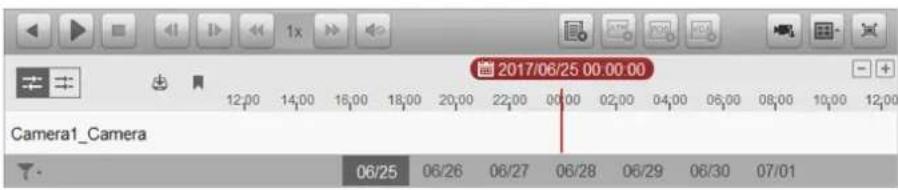
text_image
2017/06/25 00:00:00 Camera1_Camera 06/25 06/26 06/27 06/28 06/29 06/30 07/01Figure 8-1 Normal Playback Toolbar
| Icon Name | Description | |
| Single Frame (Reverse) | Play the video files frame by frame (reversely). You can also scroll down the mouse wheel to play the video file frame by frame (reversely). | |
| Event Playback Search | ch the video files recorded based on event, such as motion detection, video loss or video tampering. | |
| ATM Playback Search | ch the video files of ATM devices. | |
| POS Playback Search | ch the video files which contain POS information. | |
| VCA Playback Set VCA | rule for the searched video files that VCA event occurs, including motion detection, intrusion and line crossing. | |
| Download for Multiple Cameras | Download video files of multiple cameras at the same time. | |
| Download Download | the video files of the camera and store them to local PC. You can select to download by file, by date, or by tag. | |
| Tag Add default tag | for the video file to mark the important video point. You can edit the tag or go to the tag position via the right-click menu. | |
| 2016/05/31 10:39:37 | Accurate Positioning | Set the accurate time point to play the video file. |
| 11/30 12/01 | Date The day that has video files will be marked with . | |

The Cloud P2P device only supports normal playback and it also does not support the functions of reverse playback, slow forward or fast forward, and adding tag.
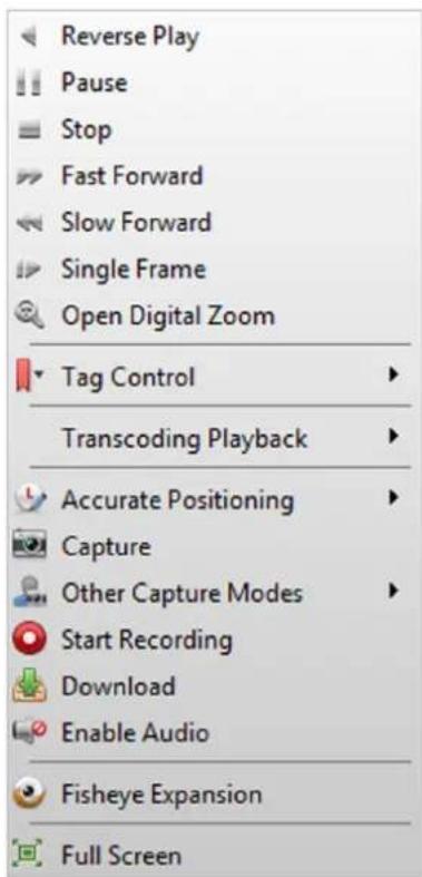
text_image
Reverse Play Pause Stop Fast Forward Slow Forward Single Frame Open Digital Zoom Tag Control Transcoding Playback Accurate Positioning Capture Other Capture Modes Start Recording Download Enable Audio Fisheye Expansion Full ScreenFigure 8-2 Right-Click Menu of Normal Playback Display Window
| Icon | Name Description |
Show/Hide Temperature InformationEnable or disable the temperature information overlay of playback image. The temperature information overlay is only supported by thermal camera. The temperature information overlay is only supported by thermal camera. | |
| Tag Control Add default (the default tag name is TAG) or custom tag (the tag name is customized) for the video file to mark the important video point. You can also edit the tag or go to the tag position conveniently. | |
| Other Capture ModesPrint Captured PictureCapture a picture and print it.Send EmailCapture the current picture and then send an Email notification to one or more receivers. The captured picture can be attached.Custom Capture |
| Icon | Name Description | |
| Capture the current picture. You can edit its name and then save it. | ||
| (YD3) | Fisheye Expansion | Enter the fisheye playback mode. For details, refer toFisheyePlayback. |
8.2.1 Search Video Files
You can search the video files by date, and you can also input keyword to filter the matched results for normal playback.
Perform this task if you need to search video files for normal playback.
Steps
-
Open the Remote Playback page.
-
Optional: Click 📋 to set the start date and end date of searching time period.

Note
In the calendar, the date which has video files recorded by schedule will be marked with ▲, and the date which has video files recorded based on event will be marked with ▲
- Start the playback of camera(s) to search the video files of the selected camera(s). You can do one of the followings to start the playback.

Note
Up to 16 cameras can be searched simultaneously.
- Drag the camera or group to a display window. - Select a display window and double-click the camera or group to start.
The matched video files of the selected group or camera will display on the right of the Remote Playback page in chronological order. And by default, the first video file will play automatically.
- Optional: Input keyword in the Filter field to filter the results.
8.2.2 Play Video Files
After searching the video files for the normal playback, you can play the video via file list or timeline.
Perform this task if you need to play the video files.
Steps
- Open the Remote Playback page.
- Search the video files.
-
Play video via file list or timeline.
-
Select the video file from the search result list, and click ▶ on the video file or double-click the video file to play the video in the playback display window.
- Click on the timeline to positioning the desired video segment of specified time for normal playback.
i Note
- The timeline indicates the time duration for the video files, and the video files of different types are color coded.
- You can use mouse wheel or click / to scale up or scale down the timeline bar.
8.3 Alarm Input Playback
When the alarm input is triggered and the linked video can be searched for alarm input playback. This function requires the support of the connected device.
For the description of the alarm input playback toolbar and right-click menu of display window, refer to Normal Playback.
i Note
Some icons may be not available for alarm input playback.
8.3.1 Search Video Files
You can search the video files by date, and you can also input keyword to filter the matched results for alarm input playback.
Perform this task when you need to search video files for alarm input playback.
Steps
- Open the Remote Playback page.
- Click ▼ to show the Alarm Input panel at the left.
- Optional: Click 📋 to set the start date and end date of searching time period.
- Start the playback of alarm input(s) to search the video files of the selected alarm input(s). You can do one of the followings to start the playback.
- Drag the alarm input to a display window.
-
Select a display window and double-click the alarm input to start.
The matched video files of the selected alarm input will display on the right of the Remote Playback page in chronological order. And by default, the first video file will play automatically. -
Optional: Input keyword in the Filter field to filter the results.
8.3.2 Play Video Files
After searching the video files for the alarm input playback, you can play the video via file list or timeline.
Perform this task when you want to play the video files of alarm input.
Steps
- Open the Remote Playback page.
- Click ▼ to show the Alarm Input panel at the left.
- Search the video files of the alarm input.

See Search Video Files for details about searching video files of the alarm input.
-
Play video via file list or timeline.
-
Select the video file from the search result list, and click ▶ on video file, or double-click the video file to play the video in the playback display window.
- Click on the timeline to positioning the desired video segment of specified time for alarm input playback.

- The timeline indicates the time duration for the video files, and the video files of different types are color coded.
- You can use mouse wheel or click ✝ to scale up or scale down the timeline bar.
8.4 Event Playback
The recorded video files triggered by event, such as motion detection, VCA detection, behavior analysis, or access control event (for video access control terminal), can be searched for event playback. This function requires the support of the connected device.
For the description of the event playback toolbar and right-click menu of display window, refer to Normal Playback.

Some icons may be not available for event playback.
8.4.1 Search Video Files
You can search the video files by date and by event type. And you can also input keyword to filter the matched results for event playback.
Perform this task when you want to search videofiles for event playback.
Steps
-
Open the Remote Playback page.
-
Select the camera and start the normal playback.
For details about starting normal playback, refer to Play Video Files.
- Click 📄 to enable event playback.
By default, the video files recorded based on motion detection will be searched.
- Optional: Click 📄 to set the start date and end date of searching time period.

In the calendar, the date which has video files recorded by schedule will be marked with ▲, and the date which has video files recorded based on event will be marked with ▲
- Select the event type from the drop-down list to start searching.
The matched video files will display on the right of the Remote Playback page in chronological order. And by default, the first video file will play automatically.
- Optional: Input keyword in the Filter field to filter the results.
8.4.2 Play Video Files
After searching the video files for the event playback, you can play the video via file list or timeline.
Before You Start
Start the normal playback of the cameras.
Perform this task when you want to play the video files recorded based on event.
Steps
-
Open the Remote Playback page.
-
Click 📄 on Remote Playback page to enable event playback.
-
Search the video files recorded based on event.
-
Play the video file.
-
Select the video file from the search result list, and click ▶ on the video file, or double-click the video file to play the video in the playback display window.
- Click on the timeline to positioning the desired video segment of specified time for event playback.

- The timeline indicates the time duration for the video files, and the video files of different types are color coded.
- You can use mouse wheel or click / to scale up or scale down the timeline bar.
8.5 ATM Playback
You can search the video files of ATM DVR for ATM playback. This function requires the support of the connected device which is configured with transaction rule.
For the description of the ATM playback toolbar and right-click menu of display window, refer to Normal Playback.

Note
Some icons may be not available for ATM playback.
8.5.1 Search Video Files
You can search the video files of ATM DVR by card number, by transaction type, by transaction amount, by file type, or by date. And you can also input keyword to filter the matched results for ATM playback.
Perform this task when you want to search video files for ATM playback.
Steps
-
Open the Remote Playback page.
-
Select the camera of ATM DVR and start the normal playback.

Note
For details about starting normal playback, refer to Play Video Files.
-
Click to enable ATM playback.
-
Set the search conditions.
by Card Number
Input the card number contained in the ATM information.
by Transaction Type and Amount
Select transaction type for search, and input the related transaction amount.
by File Type
Select the type of video files for search.
by Date
Click 📄 to set the start date and end date of searching time period.
- Click Search to start searching.
The matched video files of selected ATM DVR will display on the right of the Remote Playback page in chronological order. By default, the first video file will play automatically.
- Optional: Input keyword in the Filter field to filter the results.
8.5.2 Play Video Files
After searching the video files of the cameras connected with ATM DVR, you can play the video via file list or timeline.
Before You Start
Start the normal playback of cameras connected with ATM DVR.
Perform this task when you want to play the video files of cameras connected with ATM DVR.
Steps
- Open the Remote Playback page.
- Click on Remote Playback page to enable ATM playback.
- Search the video files of cameras connected with ATM DVR.
-
Play the video file.
-
Select the video file from the search result list, and click ▶ on the video file, or double-click the video file to play the video in the playback display window.
- Click on the timeline to positioning the desired video segment of specified time for ATM playback.

- The timeline indicates the time duration for the video files, and the video files of different types are color coded.
- You can use mouse wheel or click / to scale up or scale down the timeline bar.
8.6 POS Playback
You can search the video files which contain POS information for POS playback. This function requires the support of the connected device which is configured with POS text overlay.
For the description of the POS playback toolbar and right-click menu of display window, refer to Normal Playback.

Some icons may be not available for POS playback.
8.6.1 Search Video Files
You can search the video files which contain POS information by keywords or by date.
Perform this task when you want to search videofiles for POS playback.
Steps
-
Open the Remote Playback page.
-
Select the camera and start the normal playback.

For details about starting normal playback, refer to Play Video Files.
-
Click to enable POS playback.
-
Set the search conditions.
by Keywords
Input the card number contained in the ATM information.

Up to three keywords can be inputted for once. And each two keywords should be separated with a comma.
by Filter
For more than one keyword, you can select "or (|)" to search the POS information containing any of the keywords, or select "and(&)" to search the POS information containing all of the keywords.
by Case Sensitive
Check Case Sensitive to search the POS information by case-sensitive keywords.
by Date
Click to set the start date and end date of searching time period.
- Click Search to start searching.
The video files contain POS information will display on the right of the Remote Playback page in chronological order. And by default, the first video file will play automatically.
- Optional: Input keyword in the Filter field to filter the results.
8.6.2 Play Video Files
After searching the video files which contain POS information, you can play the video via file list or timeline.
Before You Start
Start the normal playback of cameras configured with POS information overlay.
Perform this task when you want to play the video files which contain POS information.
Steps
- Open the Remote Playback page.
- Click 📋 on Remote Playback page to enable POS playback.
- Search the video files which contain POS information.
-
Play video via file list or timeline.
-
Select the video file from the search result list, and click ▶ on the video file, or double-click the video file to play the video in the playback display window.
- Click on the timeline to positioning the desired video segment of specified time for POS playback.
i Note
- The timeline indicates the time duration for the video files, and the video files of different types are color coded.
- You can use mouse wheel or click / to scale up or scale down the timeline bar.
8.7 VCA Playback
You can set VCA rule to the searched video files and find the video that VCA event occurs, including motion, intrusion, and line crossing. This function helps to search out the video that you may be more concerned and mark it with red color.
Perform this task when you need to set VCA rule and find the video that VCA event occurs.
Steps
i Note
For some devices, you can filter the searched video files by setting the advanced attributes, such as the gender and age of the human and whether he/she wears glasses.
- Open the Remote Playback page.
- Select the camera and start the normal playback.
i Note
Refer to Play Video Files for details.
- Click to enter the VCA playback interface.
- Select the VCA Type, draw the detection region and set the sensitivity.
Motion Detection
Get all the related motion detection events that occurred in the pre-defined region.
Intrusion Detection
Detect whether there are people, vehicles and other moving objects intruding into the predefined region.
Line Crossing Detection
Bi-directionally detect people, vehicles and other moving objects that cross a virtual line.
Set Detection Region for Motion
Click ☐, and then click and move on the playback window to set the grid rectangle as the detection region.
| Set All the Area as Detection Region for Motion | Click to set all the area shot by the camera as the detection region. |
| Set Vertex of Detection Region for Intrusion | Click, and then click on the playback window to set the vertex for the detection region. |
| Set Detection Line for Line Crossing | Click, and then drag on the playback window to set the detection line. |
| Delete Drawn Region or Line Click . | ✗ |
i Note
For Intrusion and Line Crossing, you can click Advanced Attributes and filter the searched video files by setting the target characters, such as the gender and age of the human and whether he/she wears glasses. This function should be supported by the device.
-
Optional: Click 📋 to set the start date and end date of searching time period.
-
Click Search.
The VCA events occurred in the defined area will be red marked on the timeline.
i Note
- By default, the playback speed of concerned video will be 1X, and the playback speed of unconcerned video will be 8X.
-
You can set to skip the unconcerned video during VCA playback in System Configuration and the unconcerned video won't be played during VCA playback. Refer to Set Live View and Playback Parameters for details.
-
Play the video files after searching.
i Note
- Refer to Play Video Files for the description of the playback control toolbar and right-click menu.
- Some icons may not available for VCA playback.
8.8 Synchronous Playback
In synchronous playback, the video files can be played back in synchronization.
Perform this task when you need to play the video files in synchronization.
Steps
Note
Video files from up to 16 cameras can be played back simultaneously.
- Open the Remote Playback page.
- Start normal playback of at least two cameras.

Refer to Play Video Files for details.
-
Click in the toolbar to enable the synchronous playback.
The camera under playback will start synchronous playback. -
Click ➕ to disable the synchronous playback.
8.9 Fisheye Playback
You can play the video files of a fisheye camera in fisheye expansion mode.
Perform this task when you need to play video files of fisheye camera in fisheye expansion mode.
Steps

For other playback control instruction, refer to Normal Playback. Some icons may not be available for fisheye playback.
- Open the Remote Playback page.
- Select a fisheye camera to start playback.

For detailed configuration about playback and playback control, refer to Normal Playback.
- Right-click on the video file and select Fisheye Expansion to enter the Fisheye Expansion mode.

The mounting type in playback of fisheye expansion is set according to the mounting type in live view. For details, refer to Perform Live View in Fisheye Mode
- Select the expanding mode for playback as you desired. Fisheye
In the Fisheye view mode, the whole wide-angle view of the camera is displayed. This view mode is called Fisheye because it approximates the vision of a fish's convex eye. The lens produces curvilinear images of a large area, while distorting the perspective and angles of objects in the image.
In the Panorama view mode, the distorted fisheye image is transformed to normal perspective image by some calibration methods.
PTZ
The PTZ view is the close-up view of some defined area in the Fisheye view or Panorama view, and it supports the electronic PTZ function, which is also called e-PTZ.

Each PTZ view is marked on the Fisheye view and Panorama view with a specific navigation box. You can drag the navigation box on the Fisheye view or Panorama view to adjust the PTZ view, or drag the PTZ view to adjust the view to the desired angle.
- Optional: Right-click on a playing window and you can switch the selected window to full-screen mode.

You can press Esc key on the keyboard or right-click on the window and select Quit Full Screen to exit the full-screen mode.
Chapter 9 Download Video Files
During playback, you can download the video files of one camera or multiple cameras to the local PC by file, by date, or by tag.

Note
You cannot download the video files of Cloud P2P device.
9.1 Download by File
During playback, you can download the video files of the camera to the local PC by file.
Perform the following steps to download the video files by file.
Steps
- Enter Playback page and select a camera to start playback.

Note
For details about starting playback, refer to Remote Playback.
- Click on the toolbar to open Video File Downloading page.
The video files of the selected camera displays on the page.
- Check the video file(s).
The total size of the selected file(s) is calculated and shown at the bottom.
-
Click Download to start downloading the selected file(s) to the local PC.
-
Optional: Input the flow and click Set to control the downloading speed.

Note
The flow should be between 0 Kbps and 32,768 Kbps.
- Optional: Click Stop to stop downloading manually.
9.2 Download by Date
During playback, you can download the video files of the camera to the local PC by date.
Perform the following steps to download the video files by date.
Steps
- Enter Remote Playback page and select a camera to start playback.

For details about starting playback, refer to Remote Playback.
-
Click 📋 on the toolbar to open File Download page.
-
Click Download by Date tab in the File Download page.
-
Check the duration(s) to enable and click to set the start and end time.
The total size of the videos in the configured duration(s) is calculated and shown at the bottom.
- Click Download to start downloading the video file(s) of the configured duration(s) to the local PC.

The progress bar shows the downloading process.
- Optional: Input the flow and click Set to control the downloading speed.

The flow should be between 0 Kbps and 32,768 Kbps.
- Optional: Click Stop to stop downloading manually.

When downloading video file of one time duration, you can set to merge the downloaded video files in the configured time duration. For merging downloaded video files, refer to Set Live View and Playback Parameters.
9.3 Download by Tag
During playback, you can download the video files of the camera to the local PC by tag.
Perform the following steps to download the video files by tag.
Steps
- Enter Remote Playback page and select a camera to start playback.

For details about starting playback, refer to Remote Playback.
-
Click on the toolbar to open File Download page.
-
Click Download by Tag tab on the File Download page.
All added tags displays on the page.
- Check the tag(s) to select the video file(s) in the time period of 30 seconds before and after the tag time.
The total size of the selected video file(s) is calculated and shown at the bottom.
-
Click Download to start downloading the selected file(s) to the local PC.
-
Optional: Input the flow and click Set to control the downloading speed.

The flow should be between 0 Kbps and 32,768 Kbps.
- Optional: Click Stop to stop downloading manually.
9.4 Download for Multiple Cameras
During the playback of multiple cameras, you can download the video files of multiple cameras by date simultaneously.
Perform the following steps to download the videofiles of multiple cameras by date simultaneously.
Steps
- Enter Playback page and select multiple cameras to start playback.

For details about starting playback, refer to Remote Playback.
-
Click to open the Download for Multiple Cameras page.
-
Check the cameras to enable the corresponding video duration settings.
-
Set the start time and end time of video duration for each camera.
-
Optional: Check Download Player to download the player.
-
Click Download to start downloading the video files of the configured duration(s) to the local PC.
The progress bar shows the downloading process.
- Optional: Input the flow and click Set to control the downloading speed.

The flow should be between 0 Kbps and 32,768 Kbps.
- Optional: Click Stop to stop downloading manually.

Up to 16 cameras' video files can be downloaded simultaneously.
Chapter 10 Event and Alarm
You can configure the alarm of the added resources and set the linkage actions so that when the alarm is triggered, you can view the alarm details.
10.1 Alarm Configuration
You can add event detections for the added resources, such as camera, alarm input, device, access control, and trigger the linkage actions when the event occurs. For example, when motion is detected, an audible warning appears or video recording starts.

Note
- The event detection should be supported by the device before you can configure it.
- The event types of camera event vary according to different devices. Here we take the configuration of some event types as examples. For other types, refer to the user manual of the device.
10.1.1 Configure Motion Detection Alarm
A motion detection alarm is triggered when the client software detects motion within its defined area. You can set linkage actions, including alarm output, channel record, and client action for the alarm.
Perform this task when you need to configure the motion detection alarm.
Steps

Note
The configuration varies according to different devices, see the user manual of the devices for details.
- Open the Event Management page and click Camera Event tab.
- Select the camera to be configured and select Motion Detection as the event type.
- Check Enable to enable the motion detection.
- Check Enable Dynamic Analysis to mark the detected objects with green rectangles in live view and playback.
- Select the arming schedule template from the Arming Schedule field.
All-day Template
For all-day continuous arming.
Weekday Template
For working-hours continuous arming from 8:00 AM to 8:00 PM.
Template 01 to 09
Fixed templates for special schedules. You can edit the templates if needed.
Custom
Customize template as desired, see Configure Arming Schedule for details.
- Optional: Select Normal or Expert as the configuration type for some cameras.

Note
Expert mode is mainly used to configure the sensitivity and proportion of object on area of each area for different day/night switch. For details, refer to the user manual of the device.
- Select the triggered camera.

Note
To capture the picture of the triggered camera when the selected event occurs, you can also set the capture schedule and the storage in Storage Schedule. For details, refer to Remote Storage Configuration.
The image or video from the triggered camera pops up or displays on the video wall when motion detection alarm occurs.
-
Draw a defined area for the arming region.
-
Drag the mouse to draw.
- Click ☐ to set the whole video area as detection area.

Note
You can click to clear all the detection area.
- Drag the slider on the sensitivity bar to adjust the motion detection sensitivity.

Note
The larger the value is, the more sensitive the detection is.
- Check the linkage action(s) for the alarm.
Alarm Output
Enable the alarm output function. Select the alarm output port and the external device connected to the port can be controlled.
Channel Record
Start the recording of the selected cameras when alarm is triggered.
Audible Warning
The client software gives an audible warning when alarm is triggered. You can select the alarm sound for audible warning. For setting the alarm sound, refer to Set Alarm Sound.
Email Linkage
Send an email notification of the alarm information to one or more receivers.
Alarm on E-map
Display the alarm information on the E-map.
Alarm Triggered Pop-up Image
The image with alarm information pops up when alarm is triggered.

You should set the triggered camera first, see step 7 in this task for details.
Alarm Triggered Video Wall Display
Display the video of the triggered camera on the video wall when alarm is triggered.

You should set the triggered camera first, see step 7 in this task for details.
- Click Copy to... to copy the alarm parameters to other channels
- Click Save.
10.1.2 Configure Video Tampering Alarm
A video tampering alarm is triggered when the camera is covered and the monitoring area cannot be viewed. You can set the linkage actions, including alarm output and client action.
Perform this task when you need to configure the video tampering alarm.
Steps

The configuration varies according to different devices, see the user manual of the devices for details.
- Open the Event Management page and click the Camera Event tab.
- Select the camera to be configured and select Video Tampering Detection as the event type.
- Check Enable to enable the video tampering detection.
- Select the arming schedule template from the Arming Schedule field.
All-day Template
For all-day continuous arming.
Weekday Template
For working-hours continuous arming from 8:00 AM to 8:00 PM.
Template 01 to 09
Fixed templates for special schedules. You can edit the templates if needed.
Custom
Customize template as desired, see Configure Arming Schedule for details.
- Select the triggered camera.

Note
To capture the picture of the triggered camera when the selected event occurs, you can also set the capture schedule and the storage in Storage Schedule. For details, refer to Remote Storage Configuration.
The image or video from the triggered camera pops up or displays on the video wall when video tampering alarm occurs.
-
Draw a defined area for the arming region.
-
Drag the mouse to draw.
- Click ☐ to set the whole video area as the detection area.

Note
Click to clear the detection area.
-
Drag the slider on the sensitivity bar to adjust the tampering alarm sensitivity.
-
Check the linkage action(s) for the alarm.
Alarm Output
Enable the alarm output function. Select the alarm output port and the external device connected to the port can be controlled.
Audible Warning
The client software gives an audible warning when alarm is triggered. You can select the alarm sound for audible warning. For setting the alarm sound, refer to Set Alarm Sound.
Email Linkage
Send an email notification of the alarm information to one or more receivers.
Alarm on E-map
Display the alarm information on the E-map.
Alarm Triggered Pop-up Image
The image of the triggered camera pops up when alarm is triggered.

Note
You should set the triggered camera first, see step 5 in this task for details.
Alarm Triggered Video Wall Display
Display the video of the triggered camera on the video wall when alarm is triggered.

Note
You should set the triggered camera first, see step 5 in this task for details.
-
Optional: Click Copy to... to copy the alarm parameters to other cameras.
-
Click Save.
10.1.3 Configure Video Loss Alarm
When the client software cannot receive video signal from the front-end devices, the video loss alarm is triggered. You can set the linkage actions, including alarm output and client action for the alarm.
Perform this task when you need to configure video loss alarm.
Steps

Note
The configuration varies according to different devices, see the user manual of the devices for details.
- Open the Event Management page and click Camera Event tab.
- Select the camera to be configured and select Video Loss as the event type.
- Check Enable to enable the video loss alarm.
- Select the arming schedule template from the Arming Schedule field.
All-day Template
For all-day continuous arming.
Weekday Template
For working-hours continuous arming from 8:00 AM to 8:00 PM.
Template 01 to 09
Fixed templates for special schedules. You can edit the templates if needed.
Custom
Customize template as desired, see Configure Arming Schedule for details.
- Select the triggered camera.

Note
To capture the picture of the triggered camera when the selected event occurs, you can also set the capture schedule and the storage in Storage Schedule. For details, refer to .
The image or video from the triggered camera pops up or displays on the video wall when the video loss alarm occurs.
- Check the linkage action(s) for the alarm.
Alarm Output
Enable the alarm output function. Select the alarm output port and the external device connected to the port can be controlled.
Audible Warning
The client software gives an audible warning when alarm is triggered. You can select the alarm sound for audible warning. For setting the alarm sound, refer to Set Alarm Sound.
Email Linkage
Send an email notification of the alarm information to one or more receivers.
Alarm on E-map
Display the alarm information on the E-map.
Alarm Triggered Pop-up Image
The image of the triggered camera pops up when alarm is triggered.

You should set the triggered camera first, see step 5 in this task for details.
Alarm Triggered Video Wall Display
Display the video of the triggered camera on the video wall when alarm is triggered.

You should set the triggered camera first, see step 5 in this task for details.
- Optional: Click Copy to... to copy the alarm parameters to other cameras.
- Click Save.
10.1.4 Configure Audio Exception Alarm
The abnormal sounds, such as the silence, environment noise, and current noise, can be detected. Perform this task when you need to configure the audio exception alarm.
Steps

The audio exception alarm requires the support of the connected device.
- Open the Event Management page and click Camera Event tab.
- Select the camera to be configured and select Audio Exception Detection as the event type.
- Perform the following operation(s) to enable the related function of audio detection alarm.
Audio Input Detection
Sudden Increase of Sound Intensity
Check Audio Input Detection to detect the exceptions of audio input condition.
Check Sudden Increase of Sound Intensity to detect the sudden increase of the sound intensity, and it consists the settings of sensitivity and sound intensity threshold.

Sensitivity
Range [1 to 100]. The smaller the value, the more severe the change should be to trigger the detection.
Sound Intensity Threshold
Range [1 to 100]. The sound in the environment can be filtered, the louder the environment sound, the higher the value should be. You can adjust it according to the real environment.
Sudden Decrease of Sound Intensity
Check Sudden Decrease of Sound Intensity to detect the sudden decrease of the sound intensity, by which you can find the abnormal silent. For example, the electric generator makes loud noise when it's working, so it should be paid attention to if the noise drops down suddenly.
- Select the arming schedule template the Arming Schedule field.
All-day Template
For all-day continuous arming.
Weekday Template
For working-hours continuous arming from 8:00 AM to 8:00 PM.
Template 01 to 09
Fixed templates for special schedules. You can edit the templates if needed.
Custom
Customize template as desired, see Configure Arming Schedule for details.
- Select the triggered camera.
i Note
To capture the picture of the triggered camera when the selected event occurs, you can also set the capture schedule and the storage in Storage Schedule. For details, refer to Remote Storage Configuration.
The image or video from the triggered camera pops up or displays on the video wall when audio exception alarm occurs.
- Check the linkage action(s) for the alarm.
Alarm Output
Enable the alarm output function. Select the alarm output port and the external device connected to the port can be controlled.
Recording
Start the recording of the selected cameras when alarm is triggered.
Audible Warning
The client software gives an audible warning when alarm is triggered. You can select the alarm sound for audible warning. For setting the alarm sound, refer to Set Alarm Sound.
E-mail Linkage
Send an email notification of the alarm information to one or more receivers.
Alarm on E-map
Display the alarm information on the E-map.
Alarm Triggered Pop-up Image
The image of the triggered camera pops up when alarm is triggered.

You should set the triggered camera first, see step 5 in this task for details.
Alarm Triggered Video Wall Display
Display the video of the triggered camera on the video wall when alarm is triggered.

You should set the triggered camera first, see step 5 in this task for details.
- Optional: Click Copy to... to copy the alarm parameters to other cameras.
- Click Save.
10.1.5 Configure Face Detection Alarm
Face detection helps to detect the human faces within the monitoring area automatically. And a series of linkage actions will be triggered if any object is detected.
Perform this task when you need to configure the face detection alarm.
Steps

The face detection function requires the support of the connected device.
- Enter the Event Management page and click Camera Event tab.
- Select the camera to be configured and select Face Detection as the event type.
- Check Enable to enable the face detection alarm.
- Select the arming schedule template from the Arming Schedule field.
All-day Template
For all-day continuous arming.
Weekday Template
For working-hours continuous arming from 8:00 AM to 8:00 PM.
Template 01 to 09
Fixed templates for special schedules. You can edit the templates if needed.
Custom
Customize template as desired, see Configure Arming Schedule for details.
- Select the triggered camera.

To capture the picture of the triggered camera when the selected event occurs, you can also set the capture schedule and the storage in Storage Schedule. For details, refer to Remote Storage Configuration.
The image or video from the triggered camera pops up or displays on the video wall when face detection alarm occurs.
- Set the sensitivity for face detection.
- Optional: Check Enable Dynamic Analysis for Face Detection to mark the detected faces with rectangle in the live view.
- Check the linkage action(s) for the alarm.
Alarm Output
Enable the alarm output function. Select the alarm output port and the external device connected to the port can be controlled.
Channel Record
Start the recording of the selected cameras when alarm is triggered.
Audible Warning
The client software gives an audible warning when alarm is triggered. You can select the alarm sound for audible warning. For setting the alarm sound, refer to Set Alarm Sound.
Email Linkage
Send an email notification of the alarm information to one or more receivers.
Alarm on E-map
Display the alarm information on the E-map.
Alarm Triggered Pop-up Image
The image of the triggered camera pops up when alarm is triggered.

Set the triggered camera first, see step 5 in this task for details.
Alarm Triggered Video Wall Display
Display the video of the triggered camera on the video wall when alarm is triggered.

Set the triggered camera first, see step 5 in this task for details.
- Optional: Click Copy to... to copy the alarm parameters to other cameras.
- Click Save.
10.1.6 Configure Line Crossing Detection Alarm
Line crossing detection can be used for detecting people, vehicles and objects crossing a predefined virtual line. The crossing direction can be set as bidirectional, from left to right, or from right to left. And a series of linkage actions will be triggered if any object is detected.
Perform this task when you need to configure the line crossing detection alarm.
Steps
i Note
This line crossing detection function requires the support of connected device.
- Enter the Event Management page and click Camera Event tab.
- Select the camera to be configured and select Line Crossing Detection as the event type.
- Check Enable to enable the line crossing detection alarm.
i Note
For the specific speed dome, you can click Lock to prevent the speed dome from moving automatically during the configuration.
- Select the arming schedule template from the Arming Schedule field.
All-day Template
For all-day continuous arming.
Weekday Template
For working-hours continuous arming from 8:00 AM to 8:00 PM.
Template 01 to 09
Fixed templates for special schedules. You can edit the templates if needed.
Custom
Customize template as desired, see Configure Arming Schedule for details.
- Select the triggered camera.
i Note
To capture the picture of the triggered camera when the selected event occurs, you can also set the capture schedule and the storage in Storage Schedule. For details, refer to Remote Storage Configuration.
The image or video from the triggered camera pops up or displays on the video wall when line crossing detection alarm occurs.
- Configure the arming line.
1) Choose an ID for the virtual line.
iNote
For some specific speed dome, you can click PTZ to move the speed dome to the desired scene which corresponds to a virtual line ID. In this way, you can configure the different line crossing detection alarms for multiple views.
2) Select the virtual line direction as A<->B, A ->B, or B->A.
A<->B
When an object going across the line with both directions, it can be detected and alarms are triggered.
A->B
Only the object crossing the virtual line from the A side to the B side can be detected.
B->A
Only the object crossing the virtual line from the B side to the A side can be detected.
3) Click and draw a virtual line on the preview window.
i Note
- If you want to draw another virtual line, you must select another virtual line ID for it.
-
Up to 4 lines can be drawn.
4) Optional: Click and drag the virtual line to adjust its position
5) Optional: Click to delete the selected virtual line. -
Set the sensitivity between 1 and 100.
-
Check the linkage action(s) for the alarm.
Alarm Output
Enable the alarm output function. Select the alarm output port and the external device connected to the port can be controlled.
Channel Record
Start the recording of the selected cameras when alarm is triggered.
Audible Warning
The client software gives an audible warning when alarm is triggered. You can select the alarm sound for audible warning. For setting the alarm sound, refer to Set Alarm Sound.
Email Linkage
Send an email notification of the alarm information to one or more receivers.
Alarm on E-map
Display the alarm information on the E-map.
Alarm Triggered Pop-up Image
The image of the triggered camera pops up when alarm is triggered.

Set the triggered camera first, see step 5 in this task for details.
Alarm Triggered Video Wall Display
Display the video of the triggered camera on the video wall when alarm is triggered.

Set the triggered camera first, see step 5 in this task for details.
- Optional: Click Copy to... to copy the alarm parameters to other cameras.
- Click Save.
10.1.7 Configure Alarm Input Alarm
When a device's alarm input receives a signal from an external alarm device, such as smoke detector, doorbell, etc., the client software can trigger linkage actions for notification.
Before You Start
Add the alarm inputs to the client and group the alarm inputs for management.
Perform this task when you need to configure the alarm input alarm.
Steps
- Enter the Event Management page and click Alarm Input tab.
- Select the alarm input channel to be configured.
- Check Enable to enable the alarm input alarm.
- Create a name for the alarm.
- Set the alarm status according to the alarm input device.
- Select the arming schedule template from the Arming Schedule field.
All-day Template
For all-day continuous arming.
Weekday Template
For working-hours continuous arming from 8:00 AM to 8:00 PM.
Template 01 to 09
Fixed templates for special schedules. You can edit the templates if needed.
Custom
Customize template as desired, see Configure Arming Schedule for details.
- Select the triggered camera.

Note
To capture the picture of the triggered camera when the selected event occurs, you can also set the capture schedule and the storage in Storage Schedule. For details, refer to Remote Storage Configuration.
The image or video from the triggered camera pops up or displays on the video wall when alarm input alarm occurs.
- Check the linkage action(s) for the alarm.
Alarm Output
Enable the alarm output function. Select the alarm output port and the external device connected to the port can be controlled.
Channel Record
Start the recording of the selected cameras when alarm is triggered.
Audible Warning
The client software gives an audible warning when alarm is triggered. You can select the alarm sound for audible warning. For setting the alarm sound, refer to Set Alarm Sound.
Email Linkage
Send an email notification of the alarm information to one or more receivers.
Alarm on E-map
Display the alarm information on the E-map.
Alarm Triggered Pop-up Image
The image of the triggered camera pops up when alarm is triggered.

Set the triggered camera first, see step 7 in this task for details.
Alarm Triggered Video Wall Display
Display the video of the triggered camera on the video wall when alarm is triggered.

Set the triggered camera first, see step 7 in this task for details.
-
Optional: Click Copy to... to copy the alarm parameters to other alarm inputs.
-
Click Save.
10.1.8 Configure Device Exception Alarm
When the enabled type of device exception occurs, such as HDD full, HDD exception, illegal login, device offline, and so on, the linkage actions will be triggered for notification. You can set the linkage actions as desired.
Perform this task when you need to configure the device exception alarm.
Steps
-
Enter the Event Management page and click Exception tab.
-
Select the device to be configured.
-
Select the device exception type, including HDD full, HDD exception, illegal login, device offline, etc.
-
Check Enable to enable the device exception alarm.
-
Check the linkage action(s) for the alarm.
Alarm Output
Enable the alarm output function. Select the alarm output port and the external device connected to the port can be controlled.

Alarm Output is not available for device offline exception.
Audible Warming
The client software gives an audible warning when alarm is triggered. You can select the alarm sound for audible warning. For setting the alarm sound, refer to Set Alarm Sound.
Email Linkage
Send an email notification of the alarm information to one or more receivers.
-
Optional: Click Copy to... to copy the alarm parameters to other devices.
-
Click Save.
10.1.9 Configure Arming Schedule
The client provides two default arming schedule templates: All-day template and weekday template. It also provides 9 pre-defined templates. You can set the time periods in each day of the week and save the settings as pre-defined arming schedule.
Perform this task when you need to configure the pre-defined arming schedule.
Steps
-
Open the Event Management page and click Camera Event tab.
-
Select the camera to be configured and select a event type.
-
Check Enable to enable detecting the selected event type.
-
Click Edit to enter the Templates Management page.
-
Drag the cursor on the timeline to set the time periods.

Up to 8 time periods can be set for each day.
- Optional: Perform the following operation(s) to manage the time periods.
Move Move the cursor on a time period and when the cursor turns to
, drag to move the time period.
Lengthen or Move the cursor to one end of a time period, and when the cursor turns
Shorten to drag to lengthen or shorten the time period.
Delete Select a time period, and then click to delete it ✗
Delete All Click to delete all time periods.
Copy to Other Select a time period, and then click 📷 to copy the time periods settings
Dates to other dates.
- Click OK.
10.1.10 Configure Custom Arming Schedule
You can set custom arming schedule as desired.
Perform this task when you need to configure custom arming schedule.
Steps
-
Open the Event Management page and click Camera Event tab.
-
Select the camera to be configured and select an event type.
-
Check Enable to enable detecting the selected event type.
-
Select Custom from the Arming Schedule field to open the Custom Schedule page.
-
Drag the cursor on the timeline to set the time periods.

Up to 8 time periods can be set for each day.
- Optional: Perform the following operation(s) to manage the time periods.
Move Move the cursor on a time period and when the cursor turns to
, drag to move the time period.
Lengthen or Move the cursor to one end of a time period, and when the cursor turns
Shorten to drag to lengthen or shorten the time period.
Delete Select a time period, and then click to delete it ✗
Delete All Click to delete all time periods.
Copy to Other Select a time period, and then click 📋 to copy the time periods settings
Dates to other dates.
- Click Save as Schedule Template.
The custom template is saved as template 01, 02, 03... or 09.
- Click OK.
10.2 View Alarm and Event Information
The received recent alarms of all the added and armed devices, and the exceptions of the client can be displayed in the alarm event center. And you can view their information and manage them.
10.2.1 Enable Receiving Alarms from Devices
Before the client can receive the alarm information from the device, you need to arm the device first.
Perform this task when you need to enable receiving alarms from devices.
Steps
- Click Tool → Device Arming Control open Device Arming Control page.
All the added devices display on this page.
- Check device(s) to arm the selected device(s).
The icon 📁 in Arming Status column turns to 🔍, and the alarms of armed device(s) are automatically uploaded to the client when the alarm is triggered.
10.2.2 View Alarm Information
Different alarm types, including motion detection, video/audio exception, alarm input, device exception, VCA alarm, CID alarm, access control alarm, and other alarms, can display in the alarm and event center.
Before You Start
Configure the alarms in Event Management, see the configuration of different alarms (e.g., Configure Motion Detection Alarm) for details.
Perform this task when you need to view the received alarm information.
Steps
-
Enter the Alarm Event page.
-
Click in the lower-right corner of the client software to show the Alarms and Events panel, and then click □.
-
Click Alarm Event on the Control Panel.
-
Click Alarm tab.

Note
When the alarm occurs, the icon ⚠️ in the upper-left corner twinkles to call attention.
The received alarm information, including alarm time, source, details, and content displays on the page.
-
Optional: Check different alarm type(s) to filter the display of alarms.
-
Double click the alarm information to view the alarm details.
- Optional: Perform the following operation(s) after displaying the desired alarm information.
View Live Video of Triggered Camera
For alarm configured with triggered camera, click in the Live View column to view the live video and alarm picture of the triggered camera. See View Pop-up Alarm Information for details.
Send Email Notification
Click in Send Email column to send an email notification of the alarm to one or more receivers.

Configure the email settings first, see Set Email Parameters for details.
Display Alarm Video on Video Wall
Click ☐ in Live View column to display the video of the alarm triggered camera on the Video Wall. You can enter the Video Wall page to check the alarm triggered video on the screen (which is set as the alarm window). The physical video wall also displays the video.

Add the decoding device and configure the video wall first, see the topics of Video Wall for details.
Write Alarm Note
Click the Note column and input the description for the alarm.
Clear Alarm Click
, or right-click on an alarm and select Clear.
Enable/Disable Audible Warning
For alarm configured with audible warning, click or to enable or disable the audible warning for the alarm.

For configure audible warning for alarm, refer to the configuration of different alarms (e.g., Configure Motion Detection Alarm).
10.2.3 View Event Information
The exceptions of the client software, such as the live view failure, device disconnection, can display in the alarm and event center.
Perform this task to view the event information of the client.
Steps
-
Enter the Alarm Event page.
-
Click ⚠ in the lower-right corner of the client software to show the Alarms and Events panel, and then click □.
-
Click Alarm Event on the Control Panel.
-
Click Event tab.
The received event information, including occurred time and details display on the page.
-
Optional: Clear the event information.
-
Click
- Right-click on an event information and then click Clear.
10.2.4 View Pop-up Alarm Information
For the alarm configured with pop-up image, the alarm videos and pictures can display on a pop-up window when the corresponding alarm is triggered.
Before You Start
Configure the alarm linkage action as Alarm Triggered Pop-up Image, see the configuration of different alarms (e.g., Configure Motion Detection Alarm) for details.
Perform this task when you need to view the pop-up alarm information.
Steps
-
Enter the Alarm Event page.
-
Click in the lower-right corner of the client software to show the Alarms and Events panel, and then click
-
Click Alarm Event on the Control Panel.
-
Click Alarm tab.
- Click to enable alarm triggered pop-up function.
- Trigger the alarm.
An alarm window, showing the alarm video, alarm picture, and alarm details, will pop up.

text_image
Alarm Information Alarm Information: Alarm Sou... Encoding Device:Deepin... Trigger C... IP Camera5_Deepinview 1 Alarm Type: Face Picture Comparison... Alarm Time: 2017-11-25 14:42:40 Alarm Details: Trigger Camera: IP Camera5_Deepinview 1 Alarm Picture Configure ✓ Prioritize Display of Latest Alarm Prev Page Next Page You have 963 unread alarm messages. Click Next to check ExitFigure 10-1 Alarm Pop-up Window
- Perform the following operation(s) after popping up the image.
| View Alarm Video | By default, the alarm video displays in 4-window division mode. |
| NoteFor thermal camera and target capture camera, both the live video will display at the same time. | |
| View Alarm Picture | For the alarm triggered camera configured with picture storage on the storage server, the alarm picture will display on the field below the alarm video. You can also directly click Configure to set the parameters. |
| NoteFor configuring picture storage, refer to Store Picture and Video on Storage Device . | |
| Display Latest Alarms | Check Prioritize Display of Latest Alarm to replace the earliest alarm by the latest alarm, so the latest alarm window displays. Otherwise, the current alarm information displays. |
| View Previous or Next Alarm | Click Prev Page or Next Page to view the previous or next alarm information. |
10.2.5 Acknowledge Fire Source Detection Alarm
When the thermal device detects fire source during scanning, the fire source detection alarm will be triggered and the device stops moving. You can view the alarm details including alarm video and alarm picture. When the alarm is handled, you can acknowledge the alarm and the device will continue moving according to the configured path.
Before You Start
- Configure the fire source detection alarm on the client, see the configuration of different alarms (e.g., Configure Motion Detection Alarm) for details.
- Configure the fire source acknowledgment mode on the device, see the user manual of the device for details.
Perform this task when you need to acknowledge the fire source detection alarm.
Steps
- Trigger a fire source detection alarm.
-
Perform one of the following operations to view alarm details.
-
Enter Alarm Event page and click the fire source detection alarm to open the details window.
- Configure the pop-up image linkage for fire source detection alarm, and then the alarm window will pop up automatically when the alarm is triggered.
iNote
For configuring alarm pop-up image linkage, refer to the configuration of different alarms (e.g., Configure Motion Detection Alarm).
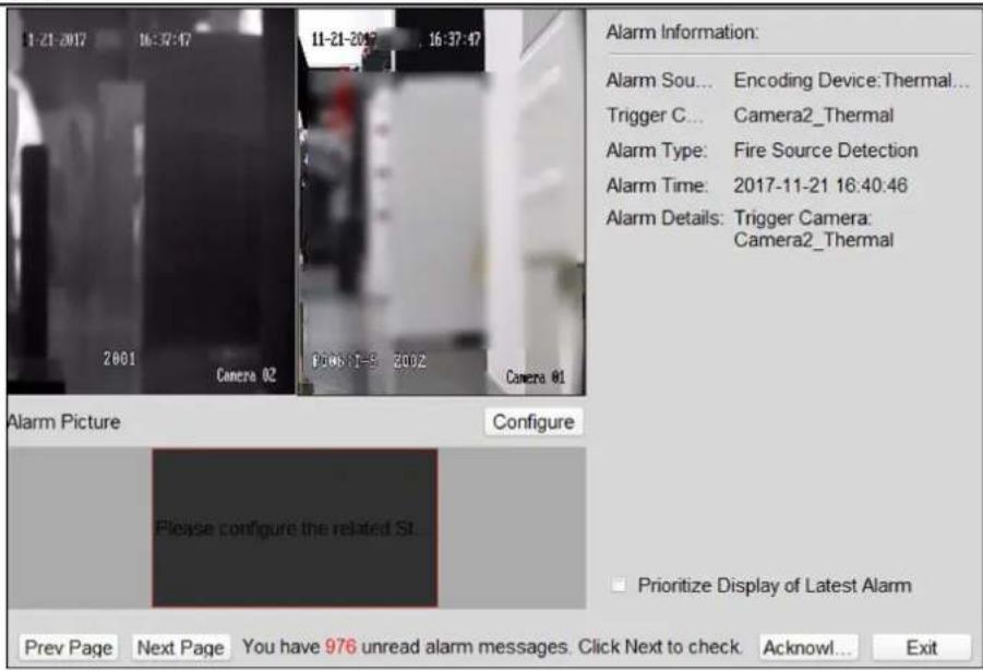
text_image
1-21-2017 16:32:47 11-21-2017 16:37:47 2001 Camera 02 03:05:17-5 2002 Camera 01 Alarm Picture Configure Please configure the related St... Prioritize Display of Latest Alarm Prev Page Next Page You have 976 unread alarm messages. Click Next to check Acknowled... Exit Alarm Information: Alarm Sou... Encoding Device:Thermal... Trigger C... Camera2_Thermal Alarm Type: Fire Source Detection Alarm Time: 2017-11-21 16:40:46 Alarm Details: Trigger Camera: Camera2_ThermalFigure 10-2 Alarm Details Window
3. Click Acknowledge.
i Note
If the acknowledgment mode is configured as Auto, the device will continue to scan automatically when the alarm is not acknowledged in the configured acknowledgment duration. For setting the acknowledgment duration, refer to the user manual of the device.
For manual acknowledgment mode, the device continues to scan according to the configured path.
Chapter 11 Map Management
The E-map function gives a visual overview of the locations and distributions of the installed cameras, alarm input devices, alarm output devices, zones, and access control points. You can get the live view of the cameras on the map, and you will get a notification message from the map when alarm is triggered.
11.1 Add Map
You should add a map as the parent map for the hot spots and hot regions.
Perform this task when you need to add a map.
Steps

Only one map can be added to one group.
-
Open the E-map page.
-
Select a group for which you want to add a map.

For details about setting the group, refer to Group Management.
-
Click in the map display area to open the map adding window.
-
Input a descriptive name of the added map as desired.
-
Click □ and select a map picture from the local path.

The picture format of the map can only be PNG, JPG or BMP.
-
Click OK.
-
Optional: Perform the following tasks after adding the map.
Zoom in/out Use the mouse wheel or click or to zoom in or zoom out on the map.
Adjust Map Area Drag the yellow window in the lower-right corner or use the direction buttons and zoom bar to adjust the map area for view.
11.2 Manage Hot Spot
The cameras, alarm inputs, and alarm outputs can be added on the map and are called the hot spots. The hot spots show the locations of the cameras, alarm inputs, and alarm outputs, and you
can also get the live view and alarm information of the surveillance scenarios through the hot spots.
i Note
- For details about managing and previewing the zone hot spot, refer to Display Zone on Map.
- For details about managing and previewing the access control point hot spot, refer to .
11.2.1 Add Camera as Hot Spot
You can add cameras to the map as hot spots.
Perform this task when you want to add cameras as hot spot on the map.
Steps
- Enter the E-map page.
- Click Edit on the E-map toolbar to enter the map editing mode.
- Click on the toolbar to open the Add Hot Spot window.
- Check the checkboxes to select the cameras to be added.
- Optional: Edit hot spot name, select the name color and select the hot spot icon by double-clicking the corresponding field.
- Click OK to save the settings.
i Note
You can also drag the camera icons from the group list to the map directly to add the hot spots.
The camera icons are added on the map as hot spots and the icons of the added cameras in the group list change from to .
11.2.2 Add Alarm Input as Hot Spot
You can add the alarm inputs to the map as hot spots.
Perform the following steps to add alarm input as hot spot on the map.
Steps
- Enter the E-map module.
- Click Edit on the E-map toolbar to enter the map editing mode.
- Click on the toolbar to open the Add Hot Spot window.
- Check the checkboxes to select the alarm inputs to be added.
- Optional: Edit hot spot name, select the name color and select the hot spot icon by double-clicking the corresponding field.
- Click OK.

Note
You can also drag the alarm input icons from the alarm input list to the map directly to add the hot spot.
The alarm input icons are added on the map as hot spots and the icons of the added alarm inputs in the group list change from to .
11.2.3 Add Alarm Output as Hot Spot
You can add the alarm outputs to the map as hot spots.
Perform the following steps to add alarm output as hot spot on the map.
Steps
-
Enter the E-map module.
-
Click Edit on the E-map toolbar to enter the map editing mode.
-
Click 📁 on the toolbar to open the Add Hot Spot window.
-
Check the checkboxes to select the alarm outputs to be added.
-
Optional: Edit the hot spot name, select the name color, and select the hot spot icon by double-clicking the corresponding field.
-
Click OK.

Note
You can also drag the alarm output icons from the alarm output list to the map directly to add the hot spot.
The alarm output are added on the map as hot spots and the icons of the added alarm outputs in the group list change from 🔒 to 🔒
11.2.4 Edit Hot Spot
You can edit the information of the added hot spots on the map, including the name, the color, the icon, etc.
Perform the following steps to edit hot spot parameters.
Steps
-
Enter the E-map module.
-
Click Edit at the lower left corner to enter the map editing mode.
-
Open the Modify Hot Spot window.
- Select the hot spot icon on the map and then click on the E-map toolbar to open the Modify Hot Spot window.
- Right-click the hot spot icon on the map and select Modify in the right-click menu to open the Modify Hot Spot window.
- Double-click the hot spot icon on the map to open the Modify Hot Spot window.
-
Edit the hot spot name in the text field, select the hot spot color, the icon, and the linked zone.
-
Click OK.
-
Optional: Delete the hot spot.
-
Select the hot spot icon and click on the toolbar to delete the hot spot.
- Right-click the hot spot icon and select Delete to delete the hot spot.
11.2.5 Preview Hot Spot
You can view the live view of the camera hot spot and the triggered alarm information of the hot spot on the map.
Perform the following steps to view the live view of the camera hot spot and the triggered alarm information of the hot spot on the map.
Steps
- Enter the E-map module.
- Click Exit Editing Mode on the E-map toolbar to enter the map preview mode.
- Get the live view of the camera.
- Double-click the camera hot spot on the map.
- Right-click the camera hot spot on the map and click Live View.
- Optional: For camera hot spot, if there is any alarm triggered, will appear and twinkle near the hot spot (it will twinkle for 10s). You can do the following operations:
| View Alarm Information | Click to view the alarm information, including the alarm type and the triggering time. |
| View Instant Playback | Right-click the camera hot spot on the map and click Live View to view the 30s instant playback. |

Note
- For DeepinMind device, the alarm picture will display near the hot spot if there is any alarm triggered. You can click and double click the alarm to view the alarm details and play back the alarm recorded video.
- To display the alarm information on the map, you should select the Alarm on E-map as the alarm linkage action. For details, refer to Alarm Configuration.
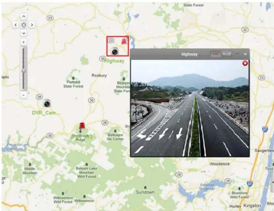
text_image
State Forest 23 Highway Roxbury Plattekill State Forest Bearpen Mountain State Forest DVR_Cam... Drybrook Ridge Belsayre Ski Center Middle Mountain Balsam Lake Mountain Wild Forest Wildemoc Wild Forest Sundown Ashigan Reservoir Bluestone Wild Forest Hurley Kingston Rhin Highway sid self Saugerties WoodstockFigure 11-1 Preview Camera Hot Spot
- Optional: For alarm output hot spot, if it is triggered, will appear and twinkle near the hot spot (it will twinkle for 10s). Right-click the alarm output hot spot on the map and click Close or Open to control the alarm output status.
11.3 Manage Hot Region
The hot region function links a map to another map.
You can manage the hot region, such as adding, editing, or deleting hot region. You can also preview the hot region.
11.3.1 Add Hot Region
You can add a map to another map as a hot region and an icon of the link to the added map is shown on the main map. The added map is called child map while the map to which you add the hot region is the parent map.
Before You Start
At least two maps should be added. Refer to Add Map for details about adding maps. Perform this task when you need to add hot region.
Steps
i Note
A map can only be added as the hot region for once.
-
Enter the E-map page.
-
Click Edit on the E-map toolbar to enter the map editing mode.
-
Select an added map as the parent map.
-
Click 📋 on the toolbar to open the Add Hot Region window.
-
Check the checkbox to select the child map.
-
Optional: Edit the hot region name, and select the hot region color and icon by double-clicking the corresponding field.
-
Click OK.
The child map icons are added on the parent map as the hot regions.
11.3.2 Edit Hot Region
You can edit the information of the hot regions on the parent map, including name, color, icon, etc.
Perform this task when you need to edit hot region.
Steps
-
Enter the E-map module.
-
Click Edit on the E-map toolbar to enter the map editing mode.
-
Open the Modify Hot Region window.
-
Select the hot region icon on the parent map and click on the toolbar.
- Right-click the hot region icon and select Modify.
-
Double-click the hot region icon.
-
Edit the hot region name and select color, icon, and the linked child map as desired.
-
Click OK.
-
Optional: Delete the hot region.
-
Select the hot region icon and click on the toolbar.
- Right-click the hot region icon and click Delete.
11.3.3 Preview Hot Region
You can view the hot spots on the hot region.
Perform this task when you need to preview hot region.
Steps
- Enter the E-map page.

Note
If you are in the editing map mode, click Exit Editing Mode on the E-map toolbar to enter the map preview mode.
You can view the hot spots on the hot region.
- Click the hot region icon to enter the linked child map.
- Optional: Click on the toolbar to go back to the parent map.
- Optional: Click 📄 on the toolbar to clear the alarm information.
Chapter 12 Statistics
Statistics module provides eight modules for data statistics via the software: heat map, people counting, counting, road traffic, face picture retrieval, license plate retrieval, behavior analysis, and captured face analysis.
12.1 Heat Map Report
Heat map is a graphical representation of data represented by colors and the heat map data can be displayed in line chart. You can use the heat map function of the camera to analyze the visit times and dwell time of customers in a configured area.
Before You Start
Add a heat map network camera to the software and properly configure the corresponding area. The added camera should have been configured with heat map rule. See Add Device for details about adding heat map network camera.
Perform this task when you need to generate a heat map report.
Steps
- Click Heat Map on the control panel to open Heat Map page.
- Select a heat map camera in the camera list.
- Select the report type as needed.
- Select By Dwell Time or By People Number as the statistics type.
- Set the start time and click Generate Heat Map to show the heat map of the camera.
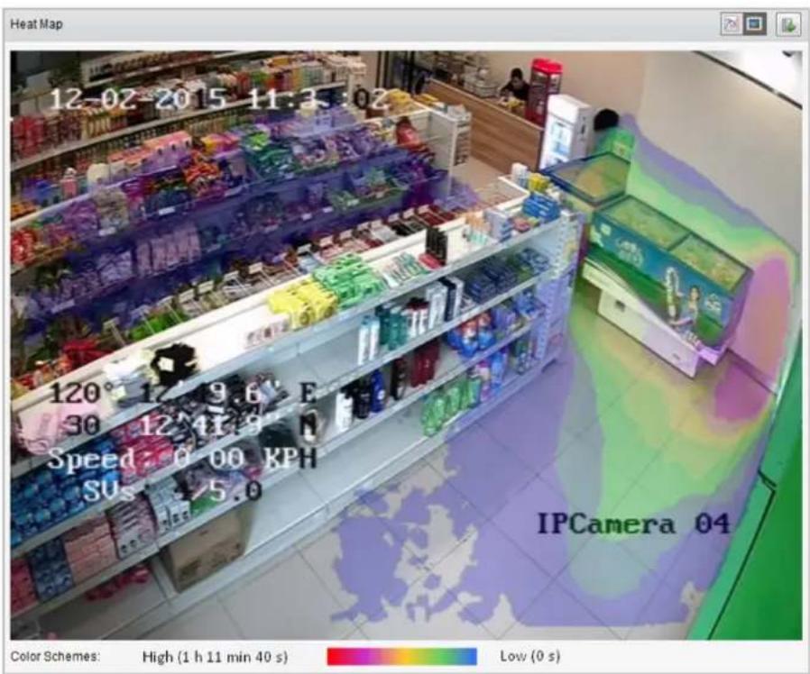
text_image
Heat Map 12-02 2015 11:3:02 120° 12' 9.6" E 30 12^41' 9" N Speed: 0 00 KPH SUs: -5.0 IPCamera 04 Color Schemes: High (1 h 11 min 40 s) Low (0 s)Figure 12-1 Results
- Optional: After generating heat map report, you can perform the following operations.
Display in Line Chart
Click to display the statistics in line chart.
Display in Picture Mode
Click to display the statistics in picture mode.
The red color block (255, 0, 0) indicates the most welcome area, and blue color block (0, 0, 255) indicates the less-popular area.
Save Statistics Data
Click to save the detailed data of heat map to your PC.
12.2 People Counting Report
You can check the people counting statistics of the added people counting device and the statistics can be displayed in line chart or histogram. You can export the detailed data for local storage.
Before You Start
Add a people counting device to the software and properly configure the corresponding area. The added device should have been configured with people counting rule. Refer to Add Device for details about adding people counting device.
Perform this task when you need to generate people counting report.
Steps
- Click People Counting on the control panel to open People Counting page.
- Select the report type as needed and set the time.
1) Select daily report, weekly report, monthly report, or annual report as the time type for the report.
2) Select the statistics type.
One Camera in Multi-period
Select one camera for generating the statistics in two time periods.
One Camera in One Period
Select one camera for generating the statistics in one time period.
3) Select the data type.
Enter
The people entered will be counted.
Exit
The people exited will be counted.
Enter and Exit
Both people entered and exited will be counted.
4) Set the time period(s).
- Select the camera for generating the report.
- Click Search to get the people counting statistics and detailed data for each hour, day, or month.
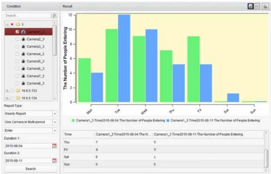
bar
| Day | Camera1_3 Time2015-08-04 The Number of People Entering | Camera1_3 Time2015-08-11 The Number of People Entering | |---|---|---| | Mon | 6 | 4 | | Tue | 10 | 12 | | Wed | 9 | 10 | | Thu | 7 | 5 | | Fri | 0 | 5 | | Sat | 0 | 1 | | Sun | 0 | 0 | The Number of People Entering Time Camera1_3 Time2015-08-04 The N... Camera1_3 Time2015-08-11 The Number of People Entering Thu 7 5 Fri 9 5 Sat 0 1 Sun 0Figure 12-2 Results
The statistics are shown in histogram form.
- Optional: Perform the following operations after search.
Switch to Line Chart Click to switch it to line chart.
i Note
By default, the statistics are shown in histogram form.
Save to Local PC
Click 📄 to save the detailed data of people counting to your PC.
12.3 Counting Report
You can check the counting statistics of the added counting device and the statistics can be displayed in line chart or histogram. You can export the detailed data for local storage.
Before You Start
Add a counting device to the software and properly configure the corresponding area. The added device should have been configured with counting settings. Refer to Add Device for details about adding counting device.
Perform this task when you need to generate counting report.
Steps
- Click Counting on the control panel to open Counting page.
- Select the report type as needed and set the time.
1) Select daily report, weekly report, monthly report, or annual report as the time type for the report.
2) Select the statistics type.
One Camera in Multi-period
Select one camera for generating the statistics in two time periods.
One Camera in One Period
Select one camera for generating the statistics in one time period.
3) Select the data type.
Enter
The people entered will be counted.
Exit:
The people exited will be counted.
Enter and Exit
Both people entered and exited will be counted.
4) Set the time period(s).
- Select the camera for generating the report.
- Click Search to get the people counting statistics and detailed data for each hour, day or month.
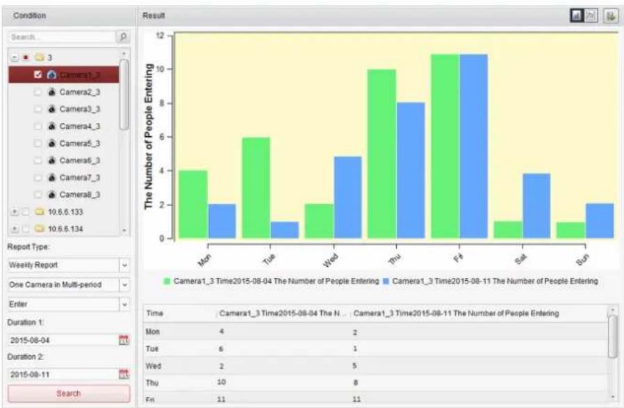
bar
| Time | Camera1_3 Time2015-08-04 The Number of People Entering | Camera1_3 Time2015-08-11 The Number of People Entering | |---|---|---| | Mon | 4 | 2 | | Tue | 6 | 1 | | Wed | 2 | 5 | | Thu | 10 | 8 | | Fri | 1 | 11 | | Sat | 1 | 4 | | Sun | 1 | 2 | The Number of People Entering (Camera1_3 Time2015-08-04) The Number of People Entering (Camera1_3 Time2015-08-11) The Number of People Entering Date: 2015-08-04 Time: Camera1_3 Time2015-08-04 The N... Camera1_3 Time2015-08-11 The Number of People Entering Mon: 4 Tue: 6 Wed: 2 Thu: 10 Fri: 11Figure 12-3 Results
The statistics are shown in histogram form. You can click to switch it to line chart.
- Optional: Click 📋 to save the detailed data of counting to your PC.
12.4 Road Traffic Report
If you add road traffic monitoring device to the client, you can search and view the captured pictures of the detected vehicle or license plate. Three types are available for searching the corresponding pictures: Vehicle Detection, Mixed-traffic Detection, and Traffic Violations.
Before You Start
- Add a road traffic monitoring device to the software and properly configure the corresponding detection area. The added device should have been configured with corresponding settings for capturing pictures. Refer to Add Device for details about adding the device.
- For Traffic Violations, add the storage server to software first and you should configure the storage server for the device and check Picture Storage and Additional Information Storage. See Store Picture and Video on Storage Device for details.
Perform this task when you need to generate a road traffic report.
Steps
-
Click Road Traffic on the control panel to open Road Traffic page.
-
Select a road traffic monitoring camera in the camera panel.
-
Set the search condition for finding the related pictures.
1) Select the query type and the pictures triggered by the event type can be found.
Vehicle Detection
Detect the passed vehicle and capture the picture of its license plate; besides, the vehicle color, vehicle logo and other information can be recognized automatically.
Mixed-traffic Detection
Search the pedestrian, motor vehicle and non-motor vehicle can be detected, and the picture of the object (for pedestrian/non-motor vehicle/motor vehicle without license plate) or license plate (for motor vehicle with license plate).
Traffic Violations
Check the captured pictures of the vehicle that violates the traffic rules (such as illegal parking and congestion).
2) Input the license plate number for searching the pictures.
3) Click to set the start time and end time.
4. Click Search.

Note
For Vehicle Detection and Mixed-traffic Detection, if no storage server is configured, the software will search the related pictures from the storage device of the local device.
5. Optional: After searching, you can perform the following operations.
| View Picture Details | Click to pop up Picture Preview window to view the captured pictures and the related information. |
| Download Picture | Check Select Current Picture or Select All on Picture Preview window and click Download, or check the checkboxes of the picture items on Road Traffic page and click Export Picture to download the selected pictures. |
12.5 Face Picture Retrieval
When the connected device (NVR or HDVR) supports face search, you can search the related picture and play the picture related video file.
12.5.1 Search Face Picture by Uploaded Picture
You can upload a face picture from your PC and compare the uploaded picture with the captured face pictures.
Before You Start
Add the device to the software and properly configure the corresponding settings. Refer to Add Device for details about adding the device.
Perform this task when you need to search the face picture by picture.
Steps

Note
This function should be supported by the connected device.
-
Click Face Picture Retrieval on the control panel to open the Face Picture Retrieval page.
-
Select device(s) in the camera panel.
-
Select Picture from the drop-down list to search by picture.
-
Select a face picture for search.
1) Click Select Picture to upload the pictures from your PC.
2) Select a detected face from uploaded picture for matching the captured face pictures.

Note
- The picture should be smaller than 4 MB.
- The resolution of the picture should be smaller than 4096 × 4080 .
-
Only JPG and JPEG formats are supported.
-
Set the similarity level.
Example
If you set the similarity as 40, the captured pictures have no less than 40% similarity with the uploaded face picture will list.
-
Set the maximum number of displayed results.
-
Click 📋 to set the start time and end time for searching the captured face pictures or video files.
-
Click Search to start searching.
The search results of the pictures are displayed in list.
- Export the pictures and save them in your PC.
Export Picture
Export all the pictures retrieval.
Export Current Page
Export the pictures in the current page.
Export Segment
You can download the pictures by packages. Each package contains up to 1,000 pictures.
- Optional: Perform secondary search based on the search result.
1) Move to the searched picture and click
All the faces in this picture will be analyzed and displayed.
2) Select a face you want to do secondary search.
3) Set the similarity and time period.
4) Click Search.
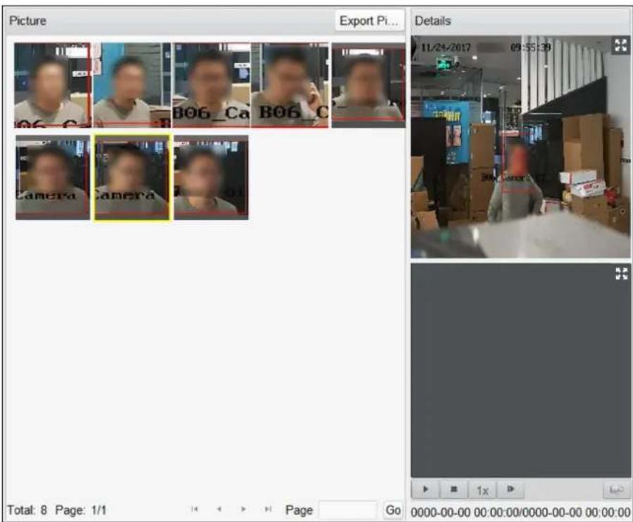
text_image
Picture Export Pi... Details 11/24/2017 09:55:39 Total: 8 Page: 1/1 Page Go 0000-00-00 00:00:00/0000-00-00 00:00:00Figure 12-4 Result
The client will search and compare the faces in the captured pictures based on the face picture you selected.
- Optional: After searching, you can do one or more the following operations.
View Details Click on a picture from the list to view details. You can also click to show the large picture, and click to restore. Play Related Videos Click ▶ play the picture's related video file in the view window on the bottom right.
i Note
- You can click ✕ to show the large video, and click ✘ to restore.
- You can click to adjust the play speed of the playback, click to play back the video files frame by frame, click to enable the audio, double-click the playback window to maximize the window.
Save Click Export Picture and select the pictures as desired to export to local Pictures to PC.
12.5.2 Search Face Picture by Event
You can search the device's captured face pictures by filtering different event types.
Before You Start
Add the device to the software and properly configure the corresponding settings. Refer to Add Device for details about adding the device.
Perform this task when you need to search the face picture by event.
Steps

Note
This function should be supported by the connected device.
- Click Face Picrure Retrieval on the control panel to open the Face Picrure Retrieval page.
- Select device(s) in the camera panel.
- Select Event Type from drop-down list to search by event type.
- Select event type.
All
Search all captured face pictures.
Face Picture Comparison
Search the captured pictures which match with the face pictures in face picture library.
Stranger Detection Alarm
Search the pictures captured when the stranger detection alarm is triggered.
- Set the maximum number of displayed results.
- Click 📋 to set the start time and end time for searching the captured face pictures or video files.
- Click Search to start searching.
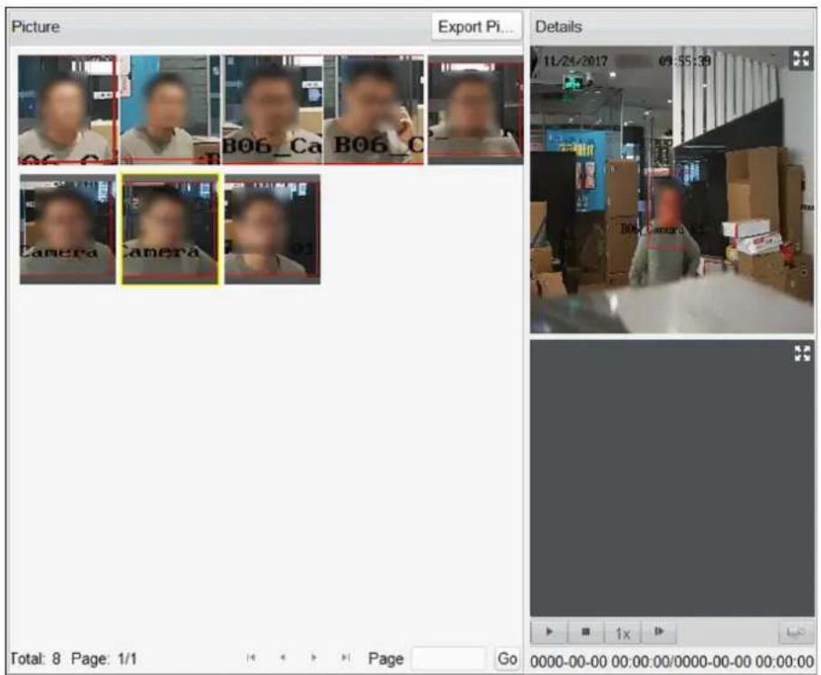
text_image
Picture Export Pi... Details 11/24/2017 09:55:39 B06_Ca B06_C Camera Camera Total: 8 Page: 1/1 Page Go 0000-00-00 00:00:00/0000-00-00 00:00:00Figure 12-5 Search Result
The search results of the pictures are displayed in list.
- Export the pictures and save them in your PC.
Export Picture
Export all the pictures retrieval.
Export Current Page
Export the pictures in the current page.
Export Segment
You can download the pictures by packages. Each package contains up to 1,000 pictures.
- Optional: Perform secondary search based on the search result
1) Move to the searched picture and click 🔒
All the faces in this picture will be analyzed and displayed.
2) Select a face you want to do secondary search.
3) Set the similarity and time period.
4) Click Search.
The client will search and compare the faces in the captured pictures based on the face picture you selected.
- Optional: After searching, you can do one or more the following operations.
View Details
Click on a picture from the list to view details. You can also click to show the large picture, and click to restore.
Play Related Videos Click ☐ to play the picture's related video file in the view window on the bottom right.
i Note
- You can click ✝ to show the large video, and click ✝ to restore.
- You can click to adjust the play speed of the playback, click to play back the video files frame by frame, click to enable the audio, double-click the playback window to maximize the window.
Save Click Export Picture and select the pictures as desired to export to local Pictures to PC.
12.5.3 Search Face Picture by Person Name
You can search the device's captured face pictures by person name.
Before You Start
Add the device to the software and properly configure the corresponding settings. Refer to Add Device for details about adding the device.
Perform this task when you need to search the face picture by person name.
Steps
i Note
This function should be supported by the connected device.
-
Click Face Picture Retrieval on the control panel to open the Face Picture Retrieval page.
-
Select device(s) in the camera panel.
-
Select Person Name from the drop-down list to search by person name.
-
Enter a keyword for the person name.
-
Set the maximum number of displayed results.
-
Click 📋 to set the start time and end time for searching the captured face pictures or video files.
-
Click Search to start searching.
The search results of the pictures are displayed in list.
- Export the pictures and save them in your PC.
Export Picture
Export all the pictures retrieval.
Export Current Page
Export the pictures in the current page.
Export Segment
You can download the pictures by packages. Each package contains up to 1,000 pictures.
- Perform secondary search based on the search result.
1) Move to the searched picture and click 🔒 All the faces in this picture will be analyzed and displayed.
2) Select a face you want to do secondary search.
3) Set the similarity and time period.
4) Click Search.
The client will search and compare the faces in the captured pictures based on the face picture you selected.
- After searching, you can do one or more the following operations.
View Details Click on a picture from the list to view details. You can also click to show the large picture, and click to restore.
Play Related Videos Click ▶o play the picture's related video file in the view window on the bottom right.

- You can click ✝ to show the large video, and click ✝ to restore.
- You can click to adjust the play speed of the playback, click to play back the video files frame by frame, click to enable the audio, double-click the playback window to maximize the window.
Save Click Export Picture and select the pictures as desired to export to local Pictures to PC. PC
12.6 License Plate Retrieval
When the connected device supports license plate search, you can search the related picture and play the picture related video file.
Before You Start
Add the device to the software and properly configure the corresponding settings. See Add Device for details about adding the device.
Perform this task when you need to search the license plate.
Steps
- Click License Plate Retrieval on the control panel to open License Plate Retrieval page.
- Select a device in the camera list.

This function should be supported by the connected device (NVR or HDVR).
-
Optional: Input the license plate number in the field for search.
-
Click 📋 to set the start time and end time for searching the matched license plate pictures.
-
Click Search to start searching.
The search results of the pictures are displayed in list.
- Optional: After searching license plate, you can perform the following operations.
View Details Click on a picture from the list to view details. You can also click to show the large picture, and click to restore.
Play Related Videos
Click to play the picture's related video file in the view window on the bottom right.
i Note
- You can click ✪ to show the large video, and click ✪ to restore.
- You can click to adjust the play speed of the playback, click to play back the video files frame by frame, click to enable the audio, double-click the playback window to maximize the window.
Save Pictures to PC
Click Export Picture and select the pictures as desired to export to local PC.
12.7 View Behavior Analysis Related Pictures and Videos
When the connected device supports behavior search, you can search the related picture and view the related pictures and video files.
Before You Start
Add the device to the software and properly configure the corresponding settings. See Add Device for details about adding the device.
Perform this task when you need to view behavior analysis related pictures and videos.
Steps
-
Enter Behavior Analysis module.
-
Select a device in the camera panel.
i Note
This function should be supported by the connected device (NVR or HDVR).
-
Select alarm type for behavior analysis report.
-
Click 📋 to set the start time and end time for searching the matched pictures.
-
Click Search to start searching.
-
Optional: After searching the behavior, you can perform the following operations.
View Details
Click on a picture from the list to view details. You can also click to show the large picture, and click to restore.
Play Related Videos
Click ▶o play the picture's related video file in the view window on the bottom right.
i Note
- You can click ✝ to show the large video, and click ✝ to restore.
- You can click to adjust the play speed of the playback, click to play back the video files frame by frame, click to enable the audio, double-click the playback window to maximize the window.
Save Pictures to PC
Click Export Picture and select the pictures as desired to export to local PC.
12.8 Human Body Picture Retrieval
For the DeepinMind device, you can search the captured human body pictures by uploading a picture from local PC. The client can compare the uploaded picture with the device's captured human body pictures.
Before You Start
Add the device to the software and properly configure the corresponding settings. Refer to Add Device for details about adding the device.
Perform this task when you need to search human body picture by picture.
Steps

Note
This function should be supported by the connected device.
- Click Human Body Retrieval on the control panel to open the Human Body Retrieval page.
- Select device(s) in the camera panel.
- Select a human body you want to search for.
1) Select By Picture as the search mode.
2) Click Select Picture to select a picture for comparison from local PC.
iNote
- The picture should be smaller than 4 MB.
- The resolution of the picture should be smaller than 4096*4080.
- Only JPG and JPEG formats are supported.
All the human bodies in this picture will be analyzed and displayed.
- Set the similarity level.
Example
If you set the similarity as 40, the captured pictures have no less than 40% similarity with the uploaded human body picture will list.
-
Set the maximum number of displayed results.
-
Click 📄 to set the start time and end time for searching the captured human body pictures or video files.
-
Click Search to start searching.
The search results of the pictures are displayed in list.
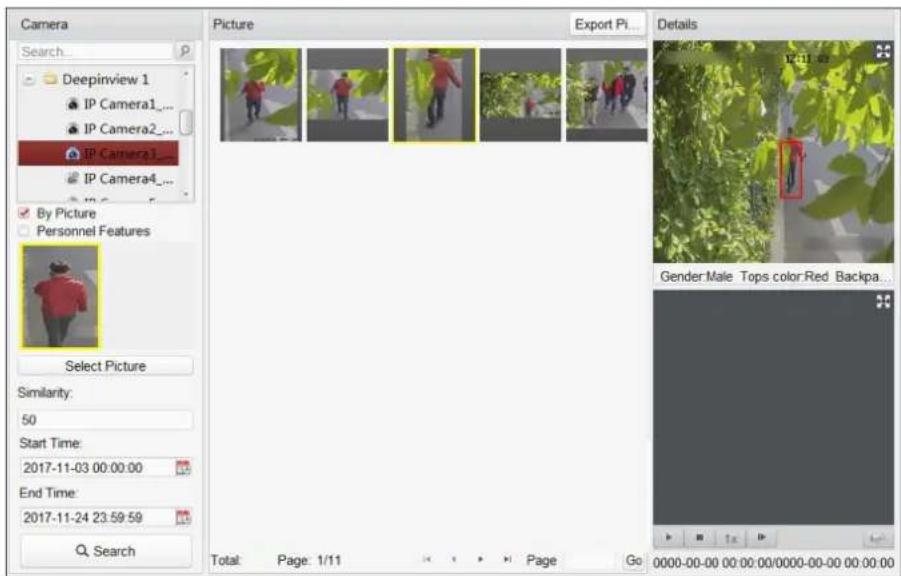
text_image
Camera Search... Deepinview 1 IP Camera1_... IP Camera2_... IP Camera1_... IP Camera4_... By Picture Personnel Features Select Picture Similarity: 50 Start Time: 2017-11-03 00:00:00 End Time: 2017-11-24 23:59:59 Q Search Picture Export Pi... Details Gender Male Tops color Red Backpa... Total Page 1/11 Page Go 0000-00-00 00:00:00/0000-00-00 00:00:00Figure 12-6 Search Result
- Optional: Perform secondary search based on the search result
1) Move to the searched picture and click
All the human bodies in this picture will be analyzed and displayed.
2) Select a human body you want to do secondary search.
3) Set the similarity and time period.
4) Click Search.
The client will search and compare the human bodies in the captured pictures based on the human body picture you selected.
- Optional: After searching human body, you can do one or more the following operations.
View Details Click on a picture from the list to view details. You can also click to show the large picture, and click to restore.
Play Related Videos Click ▶o play the picture's related video file in the view window on the bottom right.
i Note
- You can click ✝ to show the large video, and click ✝ to restore.
- You can click to adjust the play speed of the playback, click to play back the video files frame by frame, click to enable the audio, double-click the playback window to maximize the window.
Save Pictures to PC
Click Export Picture and select the pictures as desired to export to local PC.
12.9 Vehicle Retrieval
For the DeepinMind device, you can search the device's captured vehicle pictures by setting the search conditions, such as plate number, captured time, etc.
Before You Start
Add the device to the software and properly configure the corresponding settings. See Add Device for details about adding the device.
Perform this task when you need to search the vehicle.
Steps
i Note
This function should be supported by the connected device.
- Click Vehicle Retrieval on the control panel to open Vehicle Retrieval page.
- Select device(s) in the camera panel.
- Enter the keyboard of license plate number for search.
- Set the maximum number of displayed results.
- Click 📋 to set the start time and end time for searching the captured vehicle pictures or video files.
- Click Search to start searching.
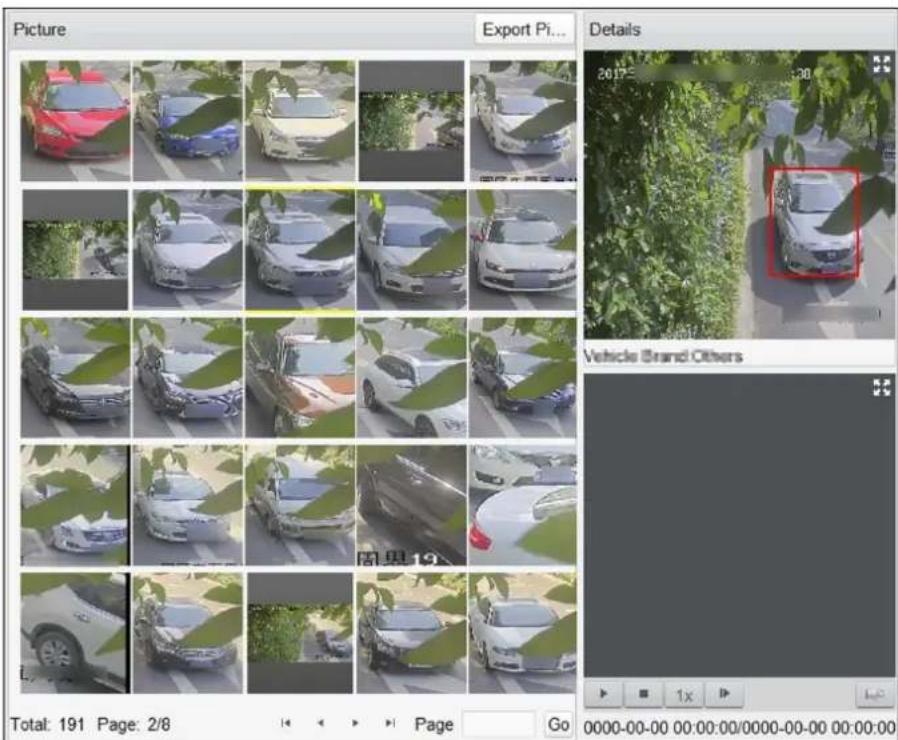
text_image
Picture Export Pi... Details 20175 Vehicle Brand Others Total: 191 Page: 2/8 Page Go 0000-00-00 00:00:00/0000-00-00 00:00:00Figure 12-7 Results
The search results of the pictures are displayed in list.
- Optional: After searching vehicle, you can perform the following operations.
View Details Click on a picture from the list to view details. You can also click to show the large picture, and click to restore.
Play Related Videos Click to play the picture's related video file in the view window on the bottom right.
i Note
- You can click ✝ to show the large video, and click ✝ to restore.
- You can click to adjust the play speed of the playback, click to play back the video files frame by frame, click to enable the audio, double-click the playback window to maximize the window.
Save Pictures to PC Click Export Picture and select the pictures as desired to export to local PC.
12.10 Queue Management
Queue management supports data analysis and report output from multiple dimensions.
Commonly Used Data Analysis
- To see queuing-up people number of a certain waiting time level in a queue/region, use queuing-up time analysis, check a target region and set a waiting time level.
- To compare queuing-up people number of a certain waiting time level in multiple queues/regions, use queuing-up time analysis, check target regions and set a waiting time level.
- To compare queuing-up people number of different waiting time levels in multiple queues/regions, use queuing-up time analysis, check target regions and set waiting time levels.
- To see the time and duration that a queue stays a certain length in a queue/region, use queue status analysis, check a target region and set a queue length level.
- To compare the time and duration that a queue stays a certain length in multiple queues/regions, use queue status analysis, check target regions and set a queue length level.
- To compare the time and duration that a queue stays at different length in multiple queues/regions, use queue status analysis, check target regions and set queue length levels.
12.10.1 Queuing-Up Time Analysis
Queuing-Up Time Analysis calculates people number of different waiting time levels. Regional comparison and multiple waiting time level comparison are supported.
Compare Queuing-up People Amount for Different Regions
You can search the queuing-up people amount for a certain waiting time level, and compare the people amount in different regions. The statistics data can show in daily report, weekly report, or monthly report.
Before You Start
Add the device to the software and properly configure the corresponding settings. See Add Device for details about adding the device.
Perform this task to compare the queuing-up people amount in different regions.
Steps

Note
This function should be supported by the connected device.
- Enter Queue Management module.
- Click Queuing-up Time Analysis Tab.
- Select Regional Comparison as the statistics type.
- Click to unfold the region list and select the region(s).
- Select a waiting time level and enter the seconds for calculating people amount waiting for the specified time period.
- Select the report type including Daily Report, Weekly Report and Monthly Report.
- Set the statistic time.

Note
You should select one date for daily report or weekly report, and select the month for monthly report. For example, if you select Weekly Report as the report type, you need to select one date and the week statistics from Monday to Sunday will be displayed in the search result.
8. Click Search to generate the statistics result.
The line chart of the calculated people amount in the specified waiting time will show on the result area. The lines with different colors indicate the people from the selected regions.
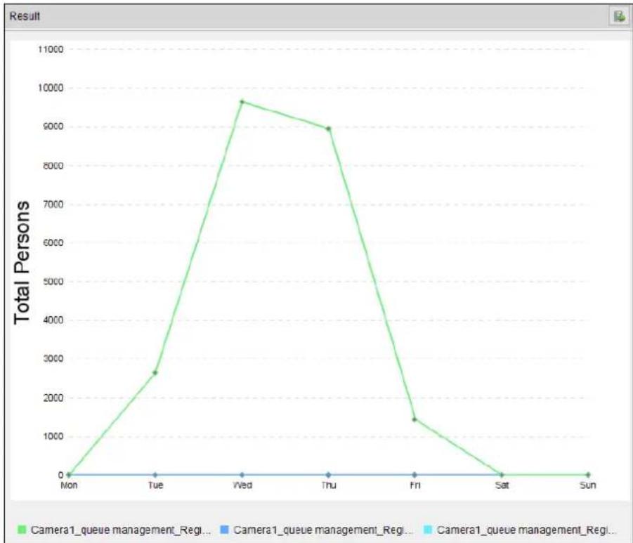
line
| Day | Total Persons | |-------|---------------| | Mon | 0 | | Tue | 2600 | | Wed | 9600 | | Thu | 8900 | | Fri | 1400 | | Sat | 0 | | Sun | 0 |Figure 12-8 Result
- Optional: Click in the upper-right corner to export the data in Excel file.
Compare Queuing-up People Amount for Different Waiting Time Levels
For a certain region, the queuing-up people amount can be calculated according to the waiting time level (e.g. the waiting time is shorter than the specified seconds.). You can search and compare the people amount for the multiple waiting time levels. The statistics data can show in daily report, weekly report, or monthly report.
Before You Start
Add the device to the software and properly configure the corresponding settings. See Add Device for details about adding the device.
Perform this task to compare the queuing-up people amount in different waiting time.
Steps
i Note
This function should be supported by the connected device.
-
Enter Queue Management module.
-
Click Queuing-up Time Analysis Tab.
-
Select Multi-level Comparison as the statistics type.
-
Click ✦ to unfold the region list and select the region(s).
-
Select the waiting time level and enter the seconds for calculating people amount waiting for the specified time period.
-
Select the report type including Daily Report, Weekly Report and Monthly Report.
-
Set the statistic time.
i Note
You should select one date for daily report or weekly report, and select the month for monthly report. For example, if you select Weekly Report as the report type, you need to select one date and the week statistics from Monday to Sunday will be displayed in the search result.
- Click Search to generate the statistics result.
The line chart of the calculated people amount in the same region will show on the result area. The lines with different colors match the waiting time levels.
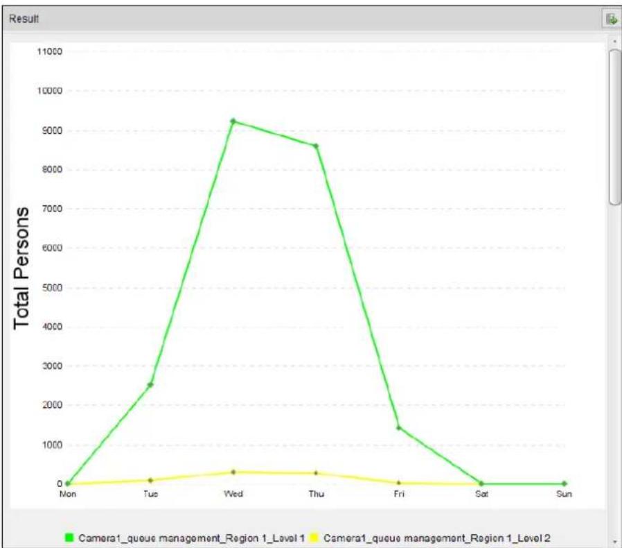
line
| Day | Camera1_queue management_Region 1_Level 1 | Camera1_queue management_Region 1_Level 2 | |-------|------------------------------------------|------------------------------------------| | Mon | 0 | 0 | | Tue | 2500 | 100 | | Wed | 9200 | 300 | | Thu | 8600 | 250 | | Fri | 1400 | 50 | | Sat | 0 | 0 | | Sun | 0 | 0 |Figure 12-9 Result
- Optional: Click 📋 in the upper-right corner to export the data in Excel file.
12.10.2 Queue Status Analysis
Queue Status Analysis calculates the time and duration that a queue stays with a certain length. Regional comparison and multiple queue length level comparison are supported.
Compare Queuing-up Duration for Different Regions
When the queue stays at a certain length, you can search and compare the durations in different regions. The statistics data can show in daily report, weekly report or monthly report.
Before You Start
Add the device to the software and properly configure the corresponding settings. See Add Device for details about adding the device.
Perform this task to compare the queuing-up duration in different regions.
Steps
i Note
This function should be supported by the connected device.
-
Enter Queue Management module.
-
Click Queue Status Analysis Tab.
-
Select Regional Comparison as the statistics type.
-
Click + to unfold the region list and select the region(s).
-
Select a queue length level and enter the value for calculating duration when the queue stays at the length.
-
Select the report type including Daily Report, Weekly Report and Monthly Report.
-
Set the statistic time.
i Note
You should select one date for daily report or weekly report, and select the month for monthly report. For example, if you select Weekly Report as the report type, you need to select one date and the week statistics from Monday to Sunday will be displayed in the search result.
- Click Search to generate the statistics result.
The line chart of the calculated duration for staying the specified queue length will show on the result area. The lines with different colors match the selected regions.
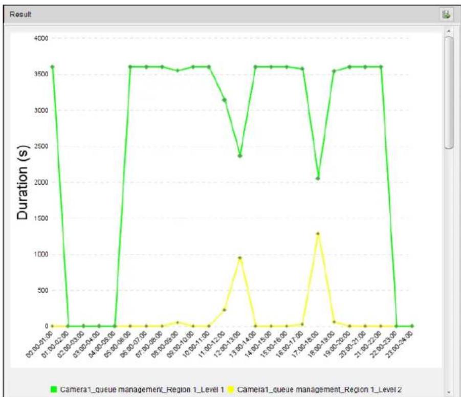
line
| Time Period | Duration (s) | | ----------------- | ------------ | | 00:00-01:00 | 3600 | | 01:00-02:00 | 0 | | 02:00-03:00 | 0 | | 03:00-04:00 | 0 | | 04:00-05:00 | 0 | | 05:00-06:00 | 3600 | | 06:00-07:00 | 3600 | | 07:00-08:00 | 3600 | | 08:00-09:00 | 3600 | | 09:00-10:00 | 3600 | | 10:00-11:00 | 3600 | | 11:00-12:00 | 3200 | | 12:00-13:00 | 2400 | | 13:00-14:00 | 3600 | | 14:00-15:00 | 3600 | | 15:00-16:00 | 3600 | | 16:00-17:00 | 3600 | | 17:00-18:00 | 2100 | | 18:00-19:00 | 3600 | | 19:00-20:00 | 3600 | | 20:00-21:00 | 3600 | | 21:00-22:00 | 3600 | | 22:00-23:00 | 3600 | | 23:00-24:00 | 360 |Figure 12-10 Result
- Optional: Click in the upper-right corner to export the data in Excel file.
Compare Queuing-up Duration for Different Queue Length Levels
For the queue in a certain region, you can search the duration when a queue stays a certain length and compare the durations for different queue length levels. The statistics data can show in daily report, weekly report, or monthly report.
Before You Start
Add the device to the software and properly configure the corresponding settings. See Add Device for details about adding the device.
Perform this task to compare the queuing-up duration for different queue length.
Steps
i Note
This function should be supported by the connected device.
-
Enter Queue Management module.
-
Click Queue Status Analysis Tab.
-
Select Multi-level Comparison as the statistics type.
-
Click ☐ to unfold the region list and select the region(s).
-
Select the queue length level and enter the value for calculating duration when the queue stays at the length.
-
Select the report type including Daily Report, Weekly Report and Monthly Report.
-
Set the statistic time.
i Note
You should select one date for daily report or weekly report, and select the month for monthly report. For example, if you select Weekly Report as the report type, you need to select one date and the week statistics from Monday to Sunday will be displayed in the search result.
- Click Search to generate the statistics result.
The line chart of the calculated duration in the same region will show on the result area. The lines with different colors match the queue length levels.
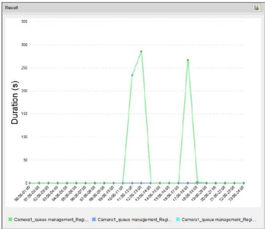
line
| Time | Duration (s) | | ------------- | ------------ | | 06:00-01:00 | 0 | | 07:00-02:00 | 0 | | 02:00-03:00 | 0 | | 03:00-04:00 | 0 | | 04:00-05:00 | 0 | | 05:00-06:00 | 0 | | 06:00-07:00 | 0 | | 07:00-08:00 | 0 | | 08:00-09:00 | 0 | | 09:00-10:00 | 0 | | 10:00-11:00 | 0 | | 11:00-12:00 | 235 | | 12:00-13:00 | 285 | | 13:00-14:00 | 285 | | 14:00-15:00 | 235 | | 15:00-16:00 | 235 | | 16:00-17:00 | 235 | | 17:00-18:00 | 235 | | 18:00-19:00 | 265 | | 19:00-20:00 | 265 | | 20:00-21:00 | 265 | | 21:00-22:00 | 265 | | 22:00-23:00 | 265 | | 23:00-24:00 | 265 |Figure 12-11 Result
- Optional: Click in the upper-right corner to export the data in Excel file.
12.11 Face Recognition Check-in
You can search for the attendance record of the persons added in face picture library during the specified period and export the data to the local PC.
Before You Start
Add the device to the software and properly configure the corresponding settings. See Add Device for details about adding the device.
Perform this task to search for the attendance record.
Steps

Note
This function should be supported by the connected device.
- Enter Face Recognition Check-in module.
- Click to unfold the camera list and select the camera(s).

Note
You can only select the cameras belongs to one device.
- Check one or multiple face picture libraries to search the persons attendance in the selected library.
- Set the date and time range for check-ins.
- Enter the maximum number of the results to show.
- Click Search to start searching.
The searched results show the attendance records including the face picture, face library, name, and check-in counts.

text_image
Attendance Record Face Library: gggg Name: 图片15 Face Recognition ... Face Library: gggg Name: 图片20 Face Recognition ... Face Library: gggg Name: 32321 Face Recognition ... Face Library: 1233... Name: 手动方式再... Face Recognition ... Face Library: gggg Name: 图片24 Face Recognition ... Face Library: gggg Name: 图片13 Face Recognition ... SISUM Face Library: gggg Name: 图片25 Face Recognition ... Face Library: gggg Name: 图片21 Face Recognition ... Face Library: gggg Name: 图片9 Face Recognition ... Face Library: gggg Name: HEBE0002... Face Recognition ... Face Library: gggg Name: 图片39 Face Recognition ... Face Library: gggg Name: 图片1 Face Recognition ... Face Library: gggg Name: 图片4 Face Recognition ... Face Library: gggg Name: 图片23 Face Recognition ... Face Library: gggg Name: r5678 Face Recognition ... Face Library: gggg Name: 图片38 Face Recognition ... Face Library: gggg Name: 图片11 Face Recognition ... Total: 36 Page: 1/2Figure 12-12 Result
- Optional: Click Export All in the upper right corner to export the data to local PC.
12.12 View People Counting in Intersections Report
Intersection analysis is used to monitor people flow and number in an intersection-like scene. The arrows in the image refer to different directions. By selecting one direction (e.g. A) as the entrance, the other directions will be set as the exits by default, so that multiple paths are generated (e.g., A to A, A to B, A to C, and A to D). You can view the people counting who passed by each path, respectively. The statistics result can show in daily, weekly, monthly, and annual report.
Before You Start
Make sure a fisheye camera which supports intersection analysis function has been configured properly and be added to the software. Refer to Add Device for details about adding the device.
Steps
- Enter Intersection Analysis module.
- Select the camera for generating the report.
- Select one direction as the entrance from the drop-down list in the Flow in filed.
- Select daily report, weekly report, monthly report, or annual report as the report type.
- Set the start time for the report.
- Click Search to get the statistics result.
The people number for each path will show on the right.
Chapter 13 View Face Picture Comparison Alarm
For the device which supports face picture comparison, you can view the captured face pictures and the matched face picture in face picture library. You can also view the face capture alarm logs and face picture comparison alarm logs.
13.1 View Captured Face Picture
You can view the real-time or historical captured face pictures. You can add the face picture to the face picture library if no result matched in the library when necessary.
Before You Start
Configure the capture rule for the device. For details, refer to the User Manual of the device Perform this task when you need to view the captured face picture.
Steps
- Click Face Picture Comparison Alarm on the control panel to enter this module.
- Click to set window division.
- Double-click the camera name after clicking a display window to start the live view.
Stop Live View
Click □ for stopping live view.
Full Screen
Click to show the full screen.
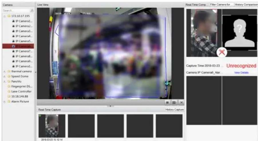
text_image
Camera Search 172.10.17.195 IP Camera1... IP Camera2... IP Camera3... IP Camera4... IP Camera5... IP Camera6... IP Camera7... IP Camera8... IP Camera9... IP Camera1... thermal camera Speed Dome PanoVu Fingerprint DS... Lane Controller 10.18.145.88 Alarm Picture Live View 2018-03-23 15:12:14 Real-Time Comp... Filter Cameras for History Comparison Capture Time 2018-03-23 Unrecognized Camera.IP Camera6_Air... View Details Real-Time Capture History Capture 2018-03-23 15:12:14Figure 13-1 View Captured Face Picture
The captured face pictures and capture time will display in the Real-Time Capture list in real time.
-
Click Filter Camera for Alarm to display the alarm pictures of the selected camera(s) that you concerned.
-
Optional: Click History Capture to view the historical captured face pictures.

Note
- Up to five pictures will be displayed in the real-time captured face pictures list.
-
Up to 100 pictures will be displayed in the historical captured face pictures list.
-
Optional: Add the captured face picture to the face picture library.
1) Click + on the upper upper-left corner of the captured face picture to open the window.
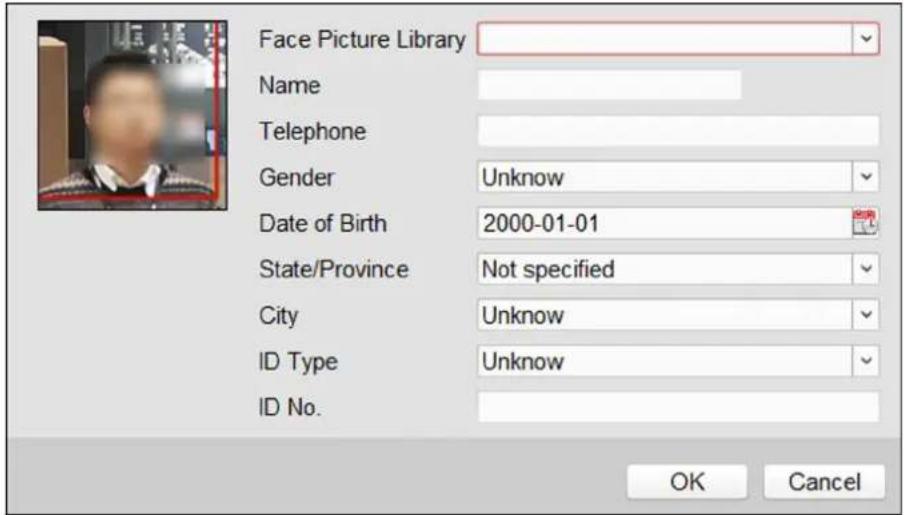
text_image
Face Picture Library Name Telephone Gender Unknown Date of Birth 2000-01-01 State/Province Not specified City Unknown ID Type Unknown ID No. OK CancelFigure 13-2 Add Face Picture to Face Picture Library
2) Select a face picture library from the drop-down list.
3) Input the person details.
4) Click OK.

Note
If the captured face picture is matched with the face picture in the library, the captured picture and picture in library will display in the Real-Time Comparison list on the right.
- Optional: Click History Comparison to view the historical matched face pictures.

Note
- Up to three real-time matched records (captured face and face in library) will be displayed in the linked face/human body pictures list.
- Up to 100 historical matched records (captured face and face in library) will be displayed in the history list.
13.2 View Matched Face Pictures
If the captured face picture matches with the face picture in the face picture library, you can view the matched person information. You can view the real-time or historical face picture comparison records.
Before You Start
Configure the capture rule for the device. For details, refer to the User Manual of the device.
Perform this task when you need to view the matched face picture.
Steps
- Click Face Picture Comparison Alarm on the control panel to enter this module.
- Click ☐ to set window division.
- Double-click the camera name after clicking a display window to start the live view.
Stop Live View
Click ■ for stopping live view.
Full Screen
Click 📄 to show the full screen.

Note
If the captured face picture is matched with the face picture in the library, the captured picture and picture in library will display in the Real-Time Comparison list on the right.
- Click Filter Camera for Alarm to display the alarm pictures of the selected camera(s) that you concerned.
- Optional: Click History Comparison to view the historical matched face pictures.

Note
- Up to three real-time matched records (captured face and face in library) will be displayed in the linked face/human body pictures list.
- Up to 100 historical matched records (captured face and face in library) will be displayed in the history list.
13.3 View Face Picture Comparison Alarm Logs
You can view the face capture alarm logs and face picture comparison alarm logs. You can also export them to the local PC.
13.3.1 Search Face Picture Comparison Alarm Logs
You can search the client logs including face capture alarm or face picture comparison alarm on the current client. You can also export the logs to the local PC.
Perform this task when you need to search the client logs, or export the logs to the local PC.
Steps
- Click Tool → Search Alarm Log on the client menu bar.
- Click to display other search conditions.
- Set the search condition, such as time period for search, alarm type, device IP address, device name, etc.
- Click Search to start searching the alarm logs.

Note
You can view the alarm logs if the camera has been configured with Storage Server to save the alarm pictures. Refer to Store Picture and Video on Storage Device for setting the picture storage on Storage Server.
The matched alarm logs will display.
- Optional: Export all the searched alarm logs, including alarm picture, device IP address, device name, alarm time, alarm details, etc.
1) Click Export All.
2) Click ☐ to select a saving path on local PC and create a name for the exported file.
3) Click OK.

The file exported is in XML file.
- Optional: Export the selected alarm logs, including alarm picture, device IP address, device name, alarm time, alarm details, etc.
1) Select the logs that you want to export.
2) Click Export Selected.
3) Click ☐ to select a saving path on local PC and create a name for the exported file.
4) Click OK.

The file exported is in XML file.
13.3.2 Open Face Picture Comparison Alarm Logs
You can open the alarm log files exported from other client and search the alarm logs by setting search conditions to view the alarm details.
Before You Start
Export the logs to the local PC. Refer to Search Face Picture Comparison Alarm Logs.
Perform this task when you need to open the alarm log file.
Steps
-
Click Tool → Search Alarm Log on the client menu bar.
-
Open the exported alarm log file.
1) Click Open.
2) Click to select an exported log file.

The log file is in XML format.
3) Click OK.
The alarm logs in the log file will display.
- Click to display other search conditions.
- Set the search condition, such as time period for search, alarm type, device IP address, device name, etc.
- Click Search to start searching the alarm logs.
The matched alarm logs will display.
Chapter 14 Show AI Information
For some devices, such as DeepinMind series, DeepinView series, and dual-lens camera, AI Dashboard function provides showing perimeter alarm (including line crossing detection, intrusion detection, region entrance detection and region existing detection) and face comparison alarm for the persons in the blacklist, VIP or regular costumers during live view. If the detected face pictures are matched with the persons in the blacklist or VIP face picture library, the security center will receive relative alarms to take appropriate actions quickly and effectively. It can also help you to evaluate the regular costumers, which is widely used in the hospital, supermarket, shopping mall and so on.
Enter AI Dashboard module, and select the camera(s) from the camera list to start live view and show AI information.

Note
This function should be supported by the device.
Camera List
The camera list on the left panel shows all the resources added to the client software, and you can select the appropriate window division and desired camera(s) to show AI information.

Note
The channels for live view at the same time are limited by the memory of the client software.
Right-click the camera in the camera list, you can switch stream type between main stream and sub-stream.
Intelligent Display
You can view the real-time video of the selected camera(s).
Click in the global toolbar of the live view area and select the window to enable the desired intelligent display. For example, if the line crossingdetection is enabled for all live view windows, the recognized targets will be marked dynamically on the images of all windows. You can also click at the bottom of each window to enable the intelligent display for the camera in this window.
Face Comparison
If you set Face Comparison switch to ON, when detecting blacklist person, VIP, or regular customer, the related alarm notification with corresponding colors will list on the right panel. You can view the alarm time, camera, and other details of the alarm.
There are three alarm types for face comparison:
Blacklist Alarm
When the captured face pictures are matched with the ones in the face picture library, the alarm will be triggered and prompt will be displayed to tell the person in the blacklist are coming.
VIP Alarm
When the captured face pictures are matched with the ones in the face picture library, the alarm will be triggered and the prompt will be displayed to tell the important persons are coming.
Regular Costumers Alarm
The persons, whose face pictures are mismatched with the ones in this face picture library and appears again during the default periods, are judged as the regular costumers and the alarm will be triggered.
Historical Captured Picture
You can view the historical captured pictures at the bottom of the page.
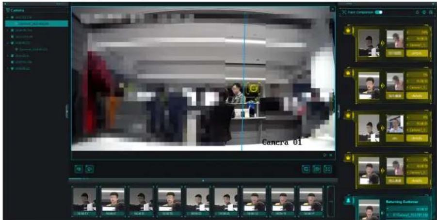
text_image
Camera Camera 01 Camera Components 1.00 2.00 3.00 4.00 5.00 6.00 7.00 8.00 9.00 10.00 11.00 12.00 13.00 14.00 15.00 16.00 17.00 18.00 19.00 20.00 21.00 22.00 23.00 24.00 25.00 26.00 27.00 28.00 29.00 30.00 31.00 32.00 33.00 34.00 35.00 36.00 37.00 38.00 39.00 40.00 41.00 42.00 43.00 44.00 45.00 46.00 47.00 48.00 49.00 50.00 51.00 52.00 53.00 54.00 55.00 56.00 57.00 58.00 59.00 60.00 61.00 62.00 63.00 64.00 65.00 66.00 67.00 68.00 69.00 70.00 71.00 72.00 73.00 74.00 75.00 76.00 77.00 78.00 79.00 80.00 81.00 82.00 83.00 84.00 85.00 86.00 87.00 88.00 89.00 90.00 91.00 92.00 93.00 94.00 95.00 96.00 97.00 98.00 99.00 100.0Figure 14-1 Show AI Information
14.1 Set Cameras for Showing AI Information
You can specify the displaying camera(s) or other cameras in the camera list to show AI information during live view. For example, if you select a camera (not in live view in the displaying window) for showing VIP information, this camera will perform static detection in the background and show the AI information about VIP.
Enter AI Dashboard module and click in the upper-right corner to select cameras for showing the AI information in real-time.
All Cameras in Live View
If check All Cameras in Live View, only the AI information of the camera(s) in live view in the displaying window can be shown.
Custom Cameras
If check Custom Cameras and select the desired cameras, the AI information of the selected camera(s) can be shown, whether the cameras are in live view or not.
14.2 Set List Types for Face Picture Libraries
You can configure list type for each face picture library of the device(s), so that the software can check whether the persons detected during live view are in the blacklist, very important person, or the regular costumers.
Enter AI Dashboard module and click in the upper-right corner to select the list type for each face picture library.

Note
This function should be supported by the device and the face picture library need be configured in the device firstly.
Blacklist
If the face picture library is set to Blacklist, AI dashboard will show the blacklist alarm once the captured pictures are matched with the ones in the face picture library.
VIP
If the face picture library is set to VIP, AI dashboard will show the VIP alarm once the captured pictures are matched with the ones in the face picture library.
Normal
The face pictures libraries which belong neither to blacklist nor VIP can be set to Normal. AI dashboard will not show any alarms when the captured face pictures are matched with the ones in the face picture library.
Chapter 15 Forward Video Stream through Stream Media Server
There is always a limit of the device remote access number. When there are many users wanting to get remote access to the device to get the live view, you can add the stream media server and get the video data stream from the stream media server, thus to lower the load of the device.
i Note
The stream media server application software needs to be installed and it is packed in the client installation package. After running the installation package, check Stream Media Server to enable the installation of stream media server.
15.1 Import Certificate to Stream Media Server
Before adding the stream media server to the client, you should import the client's security certificate to the stream media server first to perform security authentication and ensure data security.
Perform the following steps to import the security certificate to the stream media server.
Steps
- Export the certificate from the client.
1) Enter System Configuration → Service Certificate.
2) Click Export.
- Copy the certificate to the PC which has installed with stream media server.
- Click on the desktop of the PC installed with stream media server to run it.
- Import the certificate to the stream media server.
1) Right click on the task bar and click Display.
2) Click Configuration to enter the Configuration window.
3) In the security certificate field, click Import and select the certificate file you export from client in Step 1.
4) Click OK.
- Restart the stream media server to take effect.
i Note
If the client's security certificate is updated, you should export the new certificate from the client and import it to the stream media server again to update.
15.2 Add Stream Media Server
You can add the stream media server by IP address or by IP segment to the client.
If you add the stream media server by IP address, you can add one stream media server to the client each time. If you want to add multiple stream media servers with the same port number and the IP addressed in the same network segment, you can specify the start IP address and the end IP address to add them to the client.
15.2.1 Add Stream Media Server by IP Address
You can add stream media server by IP address one by one.
Perform the following steps to add stream media server by IP address.
Steps

Note
For one client, up to 16 stream media servers can be added.
- Click on the desktop to run the stream media server.

Note
- You can also forward the video through the stream media server installed on other PC.
-
If the stream media server port (value: 554) is occupied by other service, a dialog box will pop up. You should change the port No. to other value to ensure the proper running of the stream media server.
-
In the client software, enter the Device Management page and click Device.
- Add a new device type in the Device tab.
1) Click Add New Device Type.
2) Select Stream Media Server.
3) Click OK.
-
Click Stream Media Server on the list and then click Add to open the Add window.
-
Select IP Address as the adding mode.
-
Input the nickname and IP address of the stream media server.

Note
The default port value is 554.
- ClickAdd.
i Note
If the added Stream Media Server's security certificate doesn't match with the client's, it will prompt you with ⚠ after the server nickname. Move to ⚠ to view exception message and follow the provided steps to keep certificates consistent.
15.2.2 Add Stream Media Servers by IP Segment
You can add multiple stream media servers by IP segment in a batch.
Perform the following steps to add stream media server by IP segment.
Steps
i Note
For one client, up to 16 stream media servers can be added.
- Click on the desktop to run the stream media server.
i Note
- You can also forward the video through the stream media server installed on other PC.
-
If the stream media server port (value: 554) is occupied by other service, a dialog box will pop up. You should change the port No. to other value to ensure the proper running of the stream media server.
-
In the client software, enter the Device Management page and clickDevice.
-
Add a new device type in the Device tab.
1) ClickAdd New Device Type.
2) Select Stream Media Server.
3) Click OK.
-
Click Stream Media Server on the list and then click Add to open the Add window.
-
Select IP Segment as the adding mode.
-
Input the start IP and end IP address.
i Note
The default port value is 554.
- Click Add.
i Note
If the added Stream Media Server's security certificate doesn't match with the client's, it will prompt you with ⚠ after the server nickname. Move to ⚠ to view exception message and follow the provided steps to keep certificates consistent.
The steam media server of which the IP address is between the start IP and end IP will be added to the client.
15.3 Add Cameras to Stream Media Server to Forward Video Stream
To get the video stream of a camera via stream media server, you need to connect the camera to the stream media server.
Perform the following steps to add cameras to stream media server to forward video stream.
Steps
- Enter the Device Management page.
- Click Device to enter the Device tab.
- Select Stream Media Server on the Device Type panel.
- Select the stream media server from the Device Management list.
- Click Configure to enter the Stream Media Server Settings page.
- Select the cameras of which the video stream is to be forwarded via the stream media server.
- Click OK.
- Go the Main View page and start the live view of the cameras again.
On the stream media server control panel, check the channel number of the video stream forwarded through or sent from the stream media server.

Note
- For one stream media server, up to 64 channels of video stream can be forwarded through it and up to 200 channels of video stream can be sent to clients from it.
- If the camera is offline, the client can still get the live video via the stream media server.
Chapter 16 Video Wall
The Video Wall module provides the video decoding functionality, and the decoded video can be displayed on the Video Wall for an attention-grabbing performance.
16.1 Manage Encoding Device
The encoding device needs to be added to the client for decoding and displaying on the Video Wall.
16.1.1 Add Encoding Device
You should add the encoding device for decoding and displaying on the video wall. If you do not add the encoding devices in the Device Management page, you can add them in Video Wall page.
Perform this task if you need to add encoding device in Video Wall page.
Steps
- Enter the Video Wall module.
- In the Camera area, click + to open the adding device window.
-
Select the adding mode and configure the corresponding parameters for the device.
-
For IP/Domain mode, refer to Add Device by IP Address or Domain Name.
- For IP Segment mode, refer to Add Devices by IP Segment.
- For IP Server mode, refer to Add Device by IP Server.
- For HiDDNS mode, refer to Add Device by HiDDNS.
16.1.2 Add Third-Party Encoding Device
You can add third-party encoding devices to the client.
Adding third-party encoding devices by IP address or domain or by IP segment is supported.
Add Third-Party Encoding Device by IP Address or Domain Name
You can add third-party encoding device to the client by IP address or domain name for decoding and displaying on the video wall.
Perform this task if you need to add third-party encoding device to the client.
Steps
- Click Device Management on the control panel to enter the Device Management module.
- Click Device → Add New Device Type and select Third-Party Encoding Device.
-
Click Third-party Encoding Device to enter the third-party encoding device management page.
-
Click Add to open the adding device window.
-
Select the adding mode as IP/Domain.
-
Input the required information.
Channel Number
The amount of the channels.
Start From
Add the encoding device's channel from the start channel No.
Example
If you input 4 in Start From text field, it means that the starting channel No. is 4.
- Optional: Check Export to Group to create a group by the device name.

You can import all the channels of the device to the corresponding group by default.
- Click Add to add the device.
Add Third-Party Encoding Device by IP Segment
If you want add third-party encoding devices of which the IP addresses are within an IP segment for decoding and displaying on the video wall, you can specify the start IP address and end IP address, user name, password, and other parameters to add them.
Perform this task if you need to add multiple third-party encoding device to the client by IP segment.
Steps
-
Click Device Management on the control panel to enter the Device Management module.
-
Click Device → Add New Device Type and select Third-party Encoding Device.
The Third-party Encoding Device will display in the Device Type panel on the left.
-
Click Third-party Encoding Device → Add to to open the adding device window.
-
Select IP Segment as the adding mode.
-
Input the required information.
Start IP
Input the start IP address.
End IP
Input the end IP address in the same network segment with the start IP.
Channel Number
The amount of the channels.
Start From
Add the encoding device's channel from the start channel No.
- Optional: Check Export to Group to create a group by the device name.

You can import all the channels of the device to the corresponding group by default.
- Click Add to add the device.
The devices which the IP address is between the start IP and end IP will be added to the device list.
16.2 Manage Decoding Device
The decoding device needs to be added to the client to decode the video of the encoding device and display the decoded video on the Video Wall.
16.2.1 Add Decoding Device
You should add the decoding device to decode the video of the encoding device and display the decoded video on the Video Wall. If you do not add the decoding devices in the Device Management page, you can add them in Video Wall page.
Perform this task if you need to add decoding device in Video Wall page.
Steps
-
Enter the Video Wall module.
-
Click Enter Video Wall Config to enter the decoding device and video wall configuration interface.
-
In the Decoding Output area, click + to activate the Quick Adding of Decoding Device window.
-
Select the adding mode and configure the corresponding parameters for the device.
-
For IP/Domain mode, refer to Add Device by IP Address or Domain Name.
- For IP Segment mode, refer to Add Devices by IP Segment.
16.2.2 Edit Output of Decoding Device
You can edit the decoding output of the added decoding device.
Before You Start
Add decoding device to the client. For details, refer to Add Decoding Device.
Perform this task when you need to edit the decoding device's decoding output.
Steps

With the extension HDMI output board, NVR also supports decoding function:
- It can link with the video inputs and display them on the video wall without through decoding device.
- It can realize the video wall display, windowing and roaming of images of the cameras directly via the HDMI outputs.
- You can also edit the parameters of the decoding output.
-
For details, please refer to the User Manual of the NVR.
-
Enter the Video Wall module.
-
Click Enter Video Wall Config to enter the decoding device and video wall configuration interface.
-
In the Decoding Output area, click + before the decoding device to list the outputs of it.
-
Open the Modify Decoding Output window.
-
Double-click a decoding output.
-
Right-click a decoding output in the video wall area and select Decoding Output Configuration.
-
Set the display format and resolution.

Note
For HDMI and VGA outputs, you can edit configure the resolution; for BNC output, you can configure the video standard.
-
Optional: You can check Batch Configuration and select other outputs to copy the settings to.
-
Click OK to save the settings.
16.3 Configure Video Wall Settings
After adding the encoding device and decoding device to the client, you need to configure the parameters of video wall for video display.
16.3.1 Add Video Wall
You should add a virtual video wall on the client and set the video wall's window division according to actual needs before linking the decoding output to the video wall and performing further operations such as displaying live view on video wall, etc.
Perform this task when you need to add a video wall on the client.
Steps

Note
Up to 4 video walls can be added to the client.
-
Enter the Video Wall module.
-
Click Enter Video Wall Config to enter the decoding device and video wall configuration interface.
The client pre-defines a default video wall with the window division of 4*4. You can edit it if needed.
-
Open the Add Video Wall window.
-
Right- click the video wall and select Add Video Wall.
-
Click + .
-
Create a video wall name as you want.
-
Set the video wall's row and column.
-
Drag on the frames to set the row and column.
- Input the row and column in the fields.

Note
- The ranges of the row number and column number are both between 1 and 10.
-
The total number of the display windows of the video wall should be no more than 100.
-
Select the video wall's proportion.
-
Click Add.
-
After adding the video wall, you can edit or delete it if you want.
| Edit Video Wall | Right-click the video wall and select Modify Video Wall to edit the video wall's name, row number, column number, and proportion. |
| Delete Video Wall | Right-click the video wall and select Delete Video Wall, or click ✗ on the video wall tab to delete it. |
16.3.2 Link Decoding Output with Video Wall
You should link the decoding output of the added decoding device to the window of the created video wall.
Before You Start
- Add the decoding device to the client. Refer to Add Device for detailed configuration about adding decoding device.
- Add a video wall to the client. Refer to Add Video Wall for details.
Perform this task if you need to link the decoding output with the video wall.
Steps
- Enter the Video Wall module.
- Click Enter Video Wall Config to enter the decoding device and video wall configuration interface.
The decoding output of the added decoding device will display on the left and the added video wall will display on the right.
- Drag the decoding output on the left-side list to the display window of video wall, to configure the one-to-one correspondence.

You can also press and hold the Ctrl or Shift key to select multiple outputs and then drag them to the video wall for configuring linkage in batch.
- Optional: You can click ✗ in the upper-right corner of the display window to cancel the linkage.
16.4 Display Video on Video Wall
After setting encoding device, decoding device, and video wall, the video stream from encoding devices can be decoded and displayed on the Video Wall.
After enabling decoding and displaying, the captured pictures of videos from encoding devices will display on the windows of Video Wall page. And the real-time video will also display on the physical video wall.

For some kinds of decoder, the video stream from signal source (which refers to the video signal (e.g., PC) connected to decoder via local APIs) can also display on the video wall. Refer to the user manual of device for details.
16.4.1 Decode and Display
After adding decoding device and video wall, you can start decoding the video stream from encoding devices and display the video on Video Wall.
Before You Start
Add encoding and decoding devices, and link decoding output with video wall.
Perform this task when you want to enable decoding video stream and displaying video on video wall.
Steps
-
Enter the Video Wall module.
-
Click Back to Operation Page to go back to the Video Wall Operation interface.
-
Perform one of the following operations to start decoding and displaying.
-
Drag a camera from the camera list at the left panel to a decoding window, or select a decoding window and then double-click a camera.
-
Hold the Ctrl or Shift key on the keyboard and click to select multiple cameras, and then drag the selected cameras to the video wall.
-
Optional: Perform one of the following operations to save the settings for scene.

Note
Up to 8 scenes can be set for a video wall. Each scene can be configured with different settings and window divisions.
- Click on the video wall toolbar to save the settings for the current scene.
-
Click (beside) and select a scene to save the settings for.
-
Optional: Click in the Scene panel to enable the scene.
-
Optional: Get live video of camera in preview window.
1) Click at the lower-right corner of video wall to open the preview window.
2) Select a playing window or directly drag a camera to the preview window.
3) Optional: Double-click the preview window to view the live video in full screen mode.
- Optional: Expand PTZ panel at left to realize PTZ control for the camera.

Note
The camera should support PTZ control.
- Optional: Right-click on the playing window to manage the decoding and display via right-click menu.

Note
The menu differs depending on the devices.
Start/Pause Successive Decoding
Start/Pause the auto-switch decoding. This function is only supported by decoder.
Enlarge Window
Display the window in full-screen mode.
Decoding Channel Status
View the status of the decoding channel, such as decoding status, stream type.
Upload Logo
Upload a picture as the logo to the video window and set the display parameters for it. After setting, the logo shows in the defined position of the window on physical video wall.
Lock
Lock the window to disable the roaming function.
Set Alarm Window
Display the video triggered by event or alarm input on Video Wall.
Decoding Delay
Set the delay degree of the decoding according to the actual needs.
16.4.2 Perform Windowing and Roaming
Windowing is to open a new window on the screen(s). The window can be within a screen or span multiple screens. You can move the playing window within the video wall as desired and this function is called roaming.
Before You Start
The decoding output has linked to the video wall.
Perform this task if you need to set windowing and roaming.
Steps

Note
The windowing and roaming function should be supported by the decoding device.
-
Click Enter Video Wall Config to enter the decoding device and video wall configuration interface.
-
Start decoding and displaying. Refer to Decode and Display for details.
-
Drag a screen which links to a decoding output to open a window.

Note
- If you want to open a window on the opened window, drag the window and hold the Ctrl key to create one.
- At least one camera should be selected before opening window.
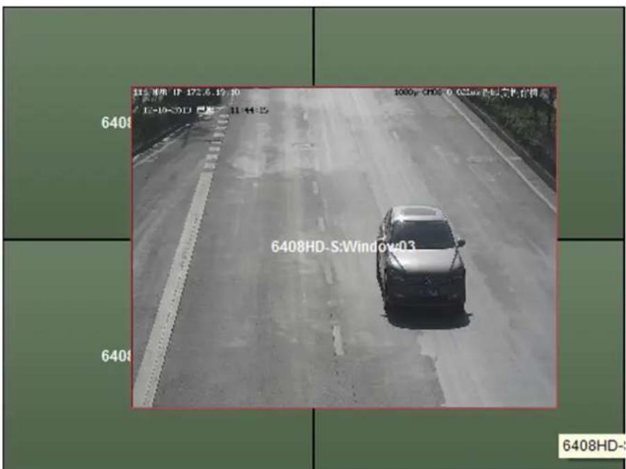
text_image
11.2.19版 IP 172.6.19.30 12-10-03 ▼ ▼ ▼ ▼ ▼ ▼ 6408HD-S:Window:03 6408HD-The window will be displayed within a screen or span multiple screens.
- Optional: Adjust the open window.
1) When the cursor becomes move the window to adjust its position.

During moving the window, the dotted borders will display. The window will be adjusted to align with the borders if it is moved to the location near the dotted borders.

text_image
6408HD-S:VGA 2 6408HD-S:VGA 3 6408HD-S:window03 6408HD-S:VGA 6Figure 16-2 Move Window
2) When the cursor becomes directional arrow, adjust the window size.

You can also hold the Shift key to scale the window in proportion.
3) Double-click the window and it will enlarge to fill the spanning screens and display on the top layer. You can double-click again to restore.
- Set the window division.
1) Select a window and click 📄 to set the window division for it.
2) Click to save the settings for it.
- Optional: You can do one or more of the following.
Disable Roaming Function
Right-click on window and select Lock in the right-click menu, and the icon 🤔 shows on the top-right corner of the window. In this way, the window cannot be moved and resized.

Note
For the locked window, you can click-and-drag to create a new window on it.
Recover Roaming Function
Right-click on the window and select Unlock in the right-click menu.
Stop Decoding of Window
Right-click on a window and select Stop Decoding in the right-click menu, or move the mouse to the window and click in the upper-right corner. The window and it will be closed.
Close All Roaming Windows
Click to close all the roaming windows.
Display the Latest Captured Picture
Right-click on a window and select Refresh in the right-click menu, or move the mouse to the window and click in the lower-right corner.
Digital Zoom
Right-click on a window and select Open Digital Zoom (if available) in the right-click menu and the cursor becomes Use the mouse to drag on the video to realize digital zoom.

Note
You can check the effect on the physical video wall.
Get a Preview of Video
Select a playing window and click the icon -to get a preview of the video in the lower-right corner of the screen. Or you can directly drag a camera to the preview window for live view.

Note
You can also double-click the preview window to get a full-screen view.
16.4.3 Display Playback on Video Wall
You can play the recorded video files on the video wall.
Before You Start
Add encoding devices stored with video files and decoders, and link decoding output with video wall.
Perform this task when you want to display playback on video wall.
Steps
i Note
Playback function is only supported by decoder.
-
Enter Video Wall module.
-
Drag a camera from the camera list on the left panel to a display window of video wall.
-
Go to the playback mode.
-
Move the cursor to the display window and click appeared at the upper-right corner.
- Right-click on the display window and select Go to Playback on the right-click menu.
For cameras with video files of current day, playback will start automatically. Otherwise, you can perform the following step to search video files for playback.
- Optional: Set time period or other search conditions and click Search at the left of playback mode page to search video files.
The searched video files will start playback automatically.
-
Optional: Control the playback.
-
Move the cursor to the playback window to show icons on the window. You can realize the functions of pausing playback, stopping playback, capturing, starting recording, going back to live view mode, and adjusting playback speed via the appeared icons.
- Right-click on the display window to control playback via the right-click menu, such as Pause, Stop, Fast Forward, Slow Forward, Capture, Start Recording, and Full-Screen.
i Note
The saving path for the captured pictures and recorded files can be configured on System Configuration page. Refer to Set File Saving Path for details.
16.4.4 Configure Auto-Switch Decoding
The auto-switch decoding refers that you can configure multiple video streams of encoding devices to one decoding output and you can set the switching interval for the decoding.
Before You Start
Add encoding devices and decoders, and link decoding output with video wall.
Perform this task when you want to set auto-switch decoding for the video wall.
Steps
i Note
The auto-switch decoding is only supported by decoder.
- Enter Video Wall Operation page.
- Click □ beside □ on the video wall toolbar to set switching interval for auto-switch decoding.
-
Drag a camera from the camera list on the left panel to a display window of video wall.
-
Move the cursor to a camera group node and click 🔒 appeared beside the node to start auto-switch decoding.
The display window of decoding output under auto-switch decoding will be marked with the upper-right corner.
Chapter 17 Security Control Panel
The Security Control Panel module provides remote control and configuration of the partitions and zones via the client software.

Note
For the users with security control panel permissions, they can enter the Security Control Panel module to manage the security control panel and real-time alarm. For setting the user permission of Security Control Panel module, refer to Account Management.
17.1 Configure Client Linkage for Zone Event
You can configure the linkages, including siren, relay, client linkage and triggered cameras, for the triggered zone events of the security control panel.
Perform this task when you need to configure the linkages for the security control panel zone's event.
Steps

Note
The zone should be disarmed before configuring the zone event linkages.
- Click Event Management → Zone Event.
- Select a zone from the list.
- Create a name for the zone.
- Select the zone type.
- Select the relay and siren to be linked.
- Check the checkboxes to configure the client linkage.
Audible Warning
The client software gives an audible warning when alarm is triggered. You can select the alarm sound for audible warning.

For setting the alarm sound, refer to Set Alarm Sound.
Email Linkage
Send an email notification of the alarm information to one or more receivers.
Alarm on E-map
Display the alarm information on the E-map.
Alarm Triggered Pop-up Image
The image with alarm information pops up when alarm is triggered.

You should set the triggered camera first.
Alarm Triggered Video Wall Display
Display the video on the Video Wall when alarm is triggered.

You should set the triggered camera first.
- Select the camera(s) to be triggered for displaying image or displaying video on the video wall when the alarm is triggered.
i Note
- To capture the picture of the triggered camera when the event occurs, you should set the capture schedule and the storage in Storage Schedule. For details, refer to Remote Storage Configuration.
-
Up to 4 cameras can be set as the triggered cameras.
-
Optional: Click Copy to... to copy the event settings to other zones.
- Click Save.
17.2 Remotely Control Security Control Panel
After adding the security control panel to the client, you can control the security control panel remotely via the client software to perform operations such as arming, disarming, bypass, group bypass, and so on for both the partitions and zones. In list mode, you can also view the device status and siren status, open or close the relay, etc.
17.2.1 Remotely Control Partitions
You can remotely control the security control panel's partitions such as away arming, stay arming, instant arming, disarming, clearing alarm, group bypass, and recovering group bypass.
Steps
- Click Security Control Panel on the control panel to enter the Security Control Panel module.
- Optional: Click ≡ or □ to at the upper right corner of the page to switch the display mode between the list or tile mode.
- Optional: Click Modify to edit the partition name as you want and change the partition display status as show or hide.
- In tile mode, click Operation to open the Partition Operation window. You can control the partitions in batch.
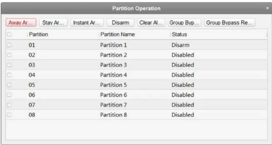
text_image
Partition Operation Away Ar... Stay Ar... Instant Ar... Disarm Clear AI... Group Byp... Group Bypass Re... Partition Partition Name Status 01 Partition 1 Disarm 02 Partition 2 Disabled 03 Partition 3 Disabled 04 Partition 4 Disabled 05 Partition 5 Disabled 06 Partition 6 Disabled 07 Partition 7 Disabled 08 Partition 8 DisabledFigure 17-1 Partition Operation Window
- Select the partition(s) to operate.
- Click the operation button (e.g., Away Arming, Stay Arming, Instant Arming, Disarm, Clear Alarm, Group Bypass or Group Bypass Recovery) to control the selected partition(s).
-
Display the partition's zone status if the partition is in alarm status.
-
For tile mode, hover the cursor over the ☐ to display the partition's zone status.
- For list mode, hover the cursor over the to display the partition's zone status.

For the details about the triggered zone alarm, refer to Handle Alarms.
17.2.2 Remotely Control Zones
You can remotely control the security control panel's zones including bypassing and recovering bypass.
Steps
- Click Security Control Panel on the control panel.
- Optional: Click ≡ or □ to at the upper right corner of the page to switch the display mode between the list or tile mode.
- Click open the Zone Operation window.
You can view the all linked zones of the partition in this window and check the zone status.
- Select the zone(s) for operation.
- Click Arm, Disarm, Bypass, or Bypass Recovery to control the selected zones.
- Optional: Click ▶ in the Live View column to view the live view of the triggered camera in the zone.
i Note
You can set the triggered camera of the zone in the Event Management module. For details, refer to Configure Client Linkage for Zone Event.
17.3 Display Zone on Map
You can add the zones on the E-map, and when the alarm in the zone is triggered, you can view the alarm notification on the E-map and check the alarm details.
Perform this task if yo need to manage the security control panel's zones on the E-map.
Steps
i Note
For detailed operations of E-map, refer to Map Management
-
Enter the E-map module.
-
Add zone on the E-map as hot spot.
1) Click Edit on the toolbar to enter the map editing mode.
2) Click on the E-map Toolbar to open the Add Hot Spot window. Or directly drag the zone icons from the group list on the left panel to the map.
3) Select the zone(s) to be added.
4) Click OK.
The zone icon(s) will be added to the map as hot spot(s) and the icon(s) of added zone(s) in the group list of the left panel will change from 📄 to .
- Preview the added hot spots.
1) Click Exit Editing Mode on the toolbar to enter the map preview mode.
2) Optional: If there is any alarm triggered in the zone, an icon will appear and twinkle near the hot spot (it will twinkle for 10s). Click the alarm icon, or right-click the hot spot icon and select Display Alarm Information, to check the alarm information, including alarm type and triggered time.
i Note
- To display the alarm information on the map, the Alarm on E-map functionality needs to be set as the alarm linkage action. For details, refer to Configure Client Linkage for Zone Event.
- You can also check the zone alarm information in the Real-time Alarm module. For details, refer to Handle Alarms.
17.4 Handle Alarms
You can view the real-time triggered CID alarm information of the security control panel and handle alarms. And you can also search the history alarms by time or by alarm type.
17.4.1 View Real-Time Alarm
You can check the real-time triggered alarm information, including alarm type, alarm time, device name, CID code, zone, partition, alarm description, etc. You can also subscribe and acknowledge the alarms, or check the triggered cameras' live view and view the linked hot spots on the E-map.
Perform this task if you need to view the real-time triggered alarm information of the added security control panel.
Steps
- Open the Real-time Alarm page.
All the real-time triggered alarms will display on this page and you can check the alarm type, alarm time, device name, user, CID code, zone, partition, alarm description, and so on.
- Optional: Check Alarm, Exception, Restore, or Operation to show the alarms in corresponding type(s).
i Note
- The Alarm type is marked with ■; the Exception type is marked with ; the Restore type is marked with ; and the Operation type is marked with .
-
The number after the alarm type indicates the alarm quantity of this type.
-
Acknowledge alarm.
-
Click in the Operation column to acknowledge the selected alarm.
- Click Acknowledge in Batch to acknowledge all the real-time triggered alarms.
The acknowledged alarm will disappear from the list.
- Optional: Click Ⓞ in the Operation column to view the live view of the triggered cameras.
i Note
Before you can get the linked live view, you should configure triggered cameras for the zone. For details about setting triggered cameras, refer to Configure Client Linkage for Zone Event.
- Optional: Click 🔒 in the Operation column to check the zone as hot spot on the map.
Before you can check the zone on the map, you should add the zone as hot spot to the map. For details about adding zone as hot spot, refer to Display Zone on Map.
- Optional: Subscribe the alarm types to receive desired alarms.
1) Click Subscribe to open the Subscribe window.
2) Click Alarm, Exception, Restore, or Operation to select the major alarm type(s).
3) Check the checkbox(es) to select the minor alarm type(s).
4) Click OK to save the selections.
17.4.2 Search History Alarm
You can search the history alarms by time and filter the searching results by alarm type. You can also handle the matched alarms.
Perform this task if you need to search the security control panel's history alarms.
Steps
i Note
For details about operating the alarms, refer to View Real-Time Alarm.
- Open the Real-time Alarm page.
- In the Real-time Alarm module, click History Alarm tab to enter the History Alarm page.
- Click 📄 to set the start time and end time of a time period.
- Click Search button and the matched alarms will display on this page.
- Optional: Filter the searching results by alarm type.
1) Click Filter button to pop up the Filter dialog.
2) Click Alarm, Exception, Restore, or Operation tab to select the major alarm type(s).

The Alarm type is marked with ■; the Exception type is marked with ■; the Restore type is marked with ; and the Operation type is marked with .
3) Check the checkbox(es) under the tab to select the minor alarm type(s).
4) Click OK to start filtering history alarms by alarm types.
- Optional: For the found alarms, click 📋 or click Acknowledge in Batch to acknowledge the unacknowledged alarms
The acknowledged alarm items will turn to gray.
- Optional: Click 🔒 and 🔒 to check the linked live view of the alarms and view the linked hot spots on the E-map.

For details about operating the alarms, refer to View Real-Time Alarm.
17.4.3 Handle Panic Alarm
For the panic alarm station, when the panic alarm is triggered, you can handle the alarm via the client. When the user calls the center from panic alarm station, the panic alarm will be triggered. Perform this task when you need to handle the panic alarm triggered from panic alarm station.
Steps
- Enter the Real-time Alarm module.
- Click 📋 on the pop-up Panic Alarm window to answer the call.
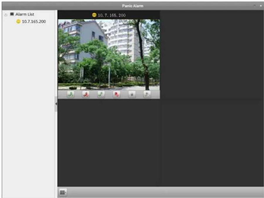
text_image
Panic Alarm Alarm List 10.7.165.200 10.7.165, 200Figure 17-2 Handle Panic Alarm
- Optional: Right-click on the live view window to open the right-click menu, and then perform the following operations.
Capture a Picture
Click to capture a picture.
Start/Stop Recording
Click / to start or stop recording.
i Note
The video file is stored in the PC.
PTZ Control If the zone is linked to the speed dome, click to enable PTZ control function on the display window. Click again to disable the function.
i Note
For setting the triggered camera, refer to Configure Client Linkage for Zone Event.
Chapter 18 Pyronix Control Panel
Pyronix control panel can be added to the client for management and control. You can control the partitions, zones, and alarm outputs of the added Pyronix control panel. After setting the zone event for the Pyronix control panel, the client can receive the alarms triggered by Pyronix control panel when the device is in alarm mode.
You can also add the zone of Pyronix control panel to the E-map, and when the alarm in the zone is triggered, you can view the alarm notification on the E-map and check the alarm details. For detailed operations for adding zone to E-map, refer to Display Zone on Map.
You can also search the operation logs stored in Pyronix control panel. For details, refer to Log Management.

Note
For the users with Pyronix control panel permissions, they can enter the Pyronix Control Panel module to manage the Pyronix control panel and real-time alarm. For setting the user permission of Pyronix Control Panel module, refer to Account Management.
18.1 Add Pyronix Control Panel
You can add the Pyronix control panel to the client in Device Management module. The device can be managed and controlled via the client once it is authorized by the device administrator on the PyronixCloud service.
Perform the following task to add Pyronix control panel to the client.
Steps
-
Open the Device Management page.
-
Display the Pyronic control panel tab on the device type panel.
1) Click Device → Add New Device Type.
2) Check Pyronix Control Panel and click OK.
The Pyronix control panel will display in the device type panel.
-
Click Pyronix Control Panel tab to enter the Pyronix control panel management page.
-
Click Add.
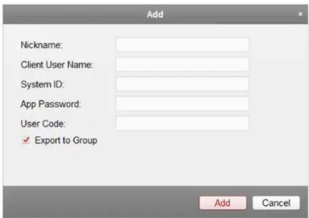
text_image
Add Nickname: Client User Name: System ID: App Password: User Code: ✓ Export to Group Add CancelFigure 18-1 Add Pyronix Control Panel
- Input the required information for adding a Pyronix control panel on the dialog.
Client User Name
Set the user name which is used for applying the permission from PyronixCloud.

See Authorize Client via PyronicCloud for details.
System ID
The system ID of the Pyronix control panel. It is a unique serial number for each control panel.

You can get the control panel ID via the device. For details, refer to the specified device user manual.
App Password
The password used to identify the control panel together with the ID on the user cloud account.

The App password should be set via the device. For details, refer to the specified device user manual.
User Code
The code for every user with different priorities to arm/disarm the control panel and perform allowed operations.

You should set the user code via the device. For details about setting the user code, refer to the specified device user manual.
- Optional: Check Export to Group to create a group by the device name.
You can import all the zones of the Pynonix control panel to the corresponding group by default.
- Click Add to add the Pyronix control panel.
- Optional: Perform the following operations after adding a Pyronix control panel.
Modify Select the device and click Modify to edit the device parameters.
Delete Select the device and click Delete to delete the device.
i Note
If it is the first time you add the Pyronix control panel to your client, after adding the Pyronix control panel, its network status is offline. You cannot manage and operate it via the control client until the administrator authorizes the client via the PyronixCloud.
What to do next
Contact the administrator to authorize the client via the PyronixCloud. For details, refer to Authorize Client via PyronicCloud.
18.2 Authorize Client via PyronicCloud
For the administrator, you need to login the PyronixCloud website to authorize the client so that the user can operate and control the Pyronix control panel via the client software.
i Note
For one computer, you should ask for authorization if it is the first time to add the Pyronix control panel.
18.2.1 Create PyronixCloud Account
Before you can authorize the client, you need to register a PyronixCloud account and connect the Pyronix control panel to PyronixCloud.
Perform the following steps to create a PyronixCloud account.
Steps
- Go to http://www.pyronixcloud.com via PC to register an account.
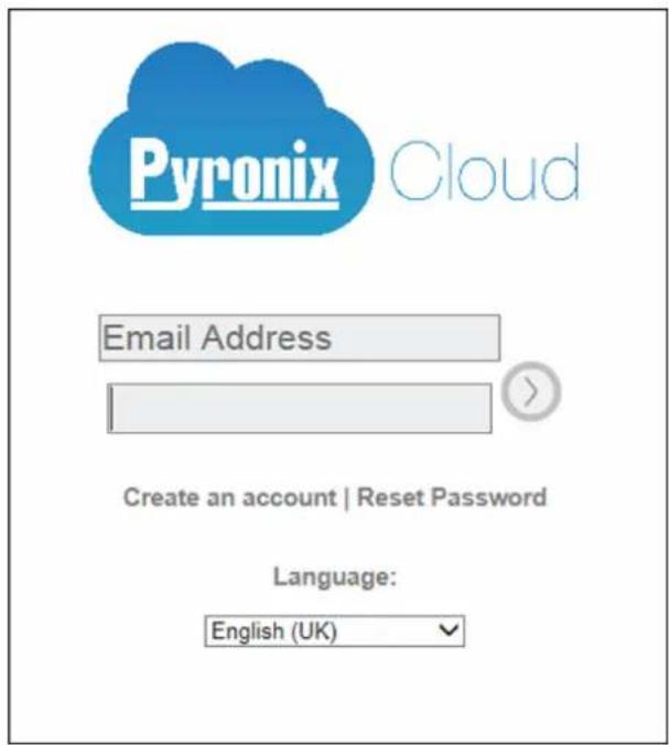
text_image
Pyronix Cloud Email Address Create an account | Reset Password Language: English (UK)Figure 18-2 Create PyronixCloud Account
- Click Create an account and complete the form.

Once the form is completed, you will receive an email from admin@pyronixcloud.com with a confirmation link. Click this link and you can log into PyronixCloud and connect your device.
- Return to PyronixClound home page and log in.
18.2.2 Connect Device to PyronixCloud
You should connect device to PyronixCloud before you can authorize the client via PyronixCloud. Perform the following steps to connect device to PyronixCloud.
Steps
- Go to http://www.pyronixcloud.com and log in to your PyronixCloud account.

If you don't have a PyronixCloud account, create one first. See Create PyronixCloud Account for details.
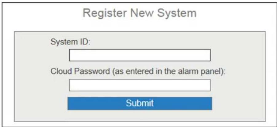
text_image
Register New System System ID: Cloud Password (as entered in the alarm panel): SubmitFigure 18-3 Connect Device to PyronixCloud
- Input the Pyronix control panel's system ID in the System ID field.
Note
The system ID is the device unique ID. You can get the system ID via the device. For details, refer to the specified device user manual.
- Input the cloud password that you entered in the Pyronix device.
i Note
The cloud password should be set via the device. For details, refer to the specified device user manual.
-
Click Submit.
-
Input a system reference to set a different name for the device.
-
Click Submit to compete the operation.
i Note
After clicking the Submit button, you will receive an email. Click the confirmation link in the email to continue.
The control panel will be appeared on View Systems interface. You can click the tick at the upper-right corner of the interface to make sure the device is connected successfully.
18.2.3 Authorize Client
If it is the first time you add the Pyronix control panel to your client, after adding the Pyronix control panel, its network status is offline. You cannot manage and operate it via the control client until the administrator authorizes the client via the PyronixCloud.
Perform the following steps to authorize the client software.
Steps
- Register a PyronixCloud account and connect the Pyronix control panel to PyronixCloud.

See Create PyronixCloud Account and Connect Device to PyronixCloud for details.
- In the View Systems page, click a user in the User column and make sure the user is from the client that you want to authorize.

The user name in the User column is the client user name you input when adding the Pyronix control panel. See Add Pyronix Control Panel for details.
-
Click next to the selected user.
-
Click Save Now to save the settings.
The icon will turn to Op
Then you can access the device via the client successfully.
| User | Last Connected | Permission | Notifications |
| 1111 | 28/03/2017 13:49:58 | On Off | ✓ Enabled |
Figure 18-4 Authorize Client via PyronixCloud
18.3 Configure Client Linkage for Pyronix Control Panel Event
You can configure the client linkage and triggered cameras for the triggered events of Pyronix control panel's zones, or for the device event of Pyronix control panel.
Perform the following steps if you need to configure linkage actions for Pyronix control panel event.
Steps
-
Open the Event Management page.
-
Click Pyronix Control Panel Event.
The added Pyronix control panel is displayed in the list on the left.
- Click + to unfold the zone list and select 🔊 to configure its zone event linkage.

You can also click 📄 to configure device event linkage for Pyronix control panel.
- In the Trigger Camera field, select the camera to be triggered for showing image when the alarm is triggered.

Note
- To capture the picture of the triggered camera when the selected event occurs, you should set the capture schedule and the storage in Storage Schedule. For details, refer to Remote Storage Configuration.
-
Up to one camera can be set as the triggered camera.
-
Check Trigger Client Action to activate the client linkage actions.
You can check the detailed actions as the client linkage. See the detailed actions below for details:
Audible Warning
The client software gives an audible warning when alarm is triggered. You can select the alarm sound for audible warning. For setting the alarm sound, refer to Set Alarm Sound.
Email Linkage
Send an email notification of the alarm information to one or more receivers.
Alarm Triggered Pop-up Image
The image with alarm information pops up when alarm is triggered.

You should set the triggered camera first.
Alarm on E-map
Display the zone's alarm information on the E-map.

This linkage is only available for device event.
- Optional: Click Copy to...to copy the event settings to other zones.
- Click Save to save the settings.
18.4 Remotely Control Pyronix Control Panel
In this section, you can control the Pyronix control panel remotely to perform operations such as arming, disarming, bypass, bypass recovery, and so on for partitions and zones. You can also control the alarm output connected to the Pyronix control panel.
18.4.1 Remotely Control Partition
You can arm and disarm the partition of the added Pyronix control panel. The status of the partitions will be displayed in real-time.
Perform this task if you need to remotely control partition.
Steps
- Click Pyronix Control Panel on the Control Panel to enter the Pyronix Control Panel page. All the added Pyronix control panels and partitions will be displayed.

Note
- The device name will turn gray if it is offline.
-
If the partition is in fault status, an ⚠️ will display near the partition name. You can hover ⚠️ to view the fault details if the partition is in fault status.
-
Optional: Click Modify to edit the partition name as you want and change the partition display status as Show or Hide.
-
Click on the switch of each partition to arm or disarm the partition.
- Optional: Hover over the ☐ to view the last operation.
18.4.2 Remotely Control Zone
You can view the zone real-time status of the added Pyronix control panel and perform bypass and bypass recovery operations to control the zone.
Perform this task when you need to remotely control the zone of Pyronix control panel.
Steps
- Click Pyronix Control Panel on the Control Panel to enter the Pyronix Control Panel module.
- Click Zone to open the Zone Control window.
The zones will be displayed.
You can view the zone details including zone No., name, and its location.
The zone's bypass status and running status are displayed in real-time.
- Perform bypass control.
Bypass Select the zone and click Bypass to bypass the zone.
Recover Select the zone and click Bypass Recovery to recover the bypass.
18.4.3 Remotely Control Connected Alarm Output
When the Pyronix control panel is connected with alarm outputs, such as siren, alarm lamp, etc., you can control the alarm output status.
Perform the following steps to remotely control connected alarm output.
Steps
- Click Pyronix Control Panel on the Control Panel to enter the Pyronix Control Panel module.
- Click Output to open the Alarm Output Control window.
Its connected alarm outputs will be displayed.
You can view the alarm output details including No., name, type, and pulse duration.
The alarm output's running status is displayed in real-time.
3. Perform alarm output control.
- Select the alarm output and click Open to turn on the alarm output.

The countdown will start in pulse time. When the countdown finishes, the output status will turn to Off automatically.
- Select the alarm output and click Close to turn off the alarm output.
Chapter 19 Access Control
The Access Control module is applicable to access control devices and video intercom. It provides multiple functionalities, including person and card management, permission configuration, access control status management, video intercom, and other advanced functions. You can also set the event configuration for access control and display access control points and zones on E-map.
i Note
For the user with access control module permissions, the user can enter the Access Control module and configure the access control settings. For setting the user permission of Access Control module, refer to Account Management.
19.1 Select Application Scenario
For the first time entering the Access Control module, you are required to select the access control's application scenario as residence or non-residence according to the actual needs.
Steps
i Note
Once the scene is configured, you cannot change it.
- Enter the Access Control module.
The Select Scene window will pop up.
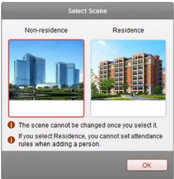
text_image
Select Scene Non-residence Residence i The scene cannot be changed once you select it. i If you select Residence, you cannot set attendance rules when adding a person. OKFigure 19-1 Select Access Control Application Scenario
- Select the scene as residence or non-residence according to the actual needs.

If you select Residence mode, you cannot configure person's attendance rule when adding a person.
- Click OK.
19.2 Configure Device Parameters
After adding the access control device, you can set its parameters such as network parameters, capture parameters, RS-485 parameters, Wiegand parameters, etc.
19.2.1 Set Network Parameters
After adding the access control device, you can set the device log uploading mode, and create EHome account via wired or wireless network.
Set Log Uploading Mode
You can set the mode for uploading logs via EHome protocol.
Steps
- Enter the Device Management module.
-
Select an access control device in the device list and click Modify.
-
Click Network Settings → Uploading Mode to enter the Uploading Mode page.
- Select the center group from the drop-down list.
- Check Enable to enable to set the uploading mode.
- Select the uploading mode from the drop-down list.
- Enable N1 or G1 for the main channel and the backup channel.
- Select Close to disable the main channel or the backup channel

The main channel and the backup channel cannot enable N1 or G1 at the same time.
- Click Save.
Create EHome Account in Wire Communication Mode
You can set the account for EHome protocol in wire communication mode. Then you can add devices via EHome protocol.
Steps

This function should be supported by the device
- Enter the Device Management module.
- Select an access control device in the device list and click Modify.
- Click Network Settings → Network Center to enter the Network Center page.
- Select the center group from the drop-down list.
- Select the Address Type as IP Address or Domain Name.
- Input IP address or domain name according to the address type.
- Input the port number for the protocol.

The port number of the wireless network and wired network should be consistent with the port number of EHome.
- Select the Protocol Type as EHome.
- Set an account name for the network center.
- Click Save.
Create EHome Account in Wireless Communication Mode
You can set the account for EHome protocol in wireless communication mode. Then you can add devices via EHome protocol.
Steps
i Note
This function should be supported by the device
- Enter the Device Management module.
- Select an access control device in the device list and click Modify.
- Click Network Settings → Wireless Communication Center to enter the Wireless Communication Center page.
- Select the APN Name as CMNET or UNINET.
- Input the SIM Card No.
- Select the center group from the drop-down list.
- Input the IP address and port number.
i Note
- By default, the port number for EHome is 7660.
-
The port number of the wireless network and wired network should be consistent with the port number of EHome.
-
Select the Protocol Type as EHome.
-
Set an account name for the network center.
-
Click Save.
19.2.2 Set Device Capture Parameters
You can configure the device capture parameters, including manual capture and linked capture.
i Note
- The Capture Settings should be supported by the device.
- Before setting the capture setting, you should configure the Storage Server for picture storage. For details, refer to Remote Storage Configuration.
Set Triggered Capture Parameters
You can set the triggered capture parameters for the device with capture function.
Before You Start
Before setting the capture setting, you should configure the storage server for picture storage. For details, refer to Remote Storage Configuration.
Steps
i Note
This function should be supported by the device
- Enter the Device Management module.
- Select an access control device in the device list and click Modify.
- Click Capture Settings → Linked Capture to enter the Linked Capture page.
- Set the picture size and quality.
- Set the capture times once triggered.
- Set the capture interval according to the capture times.
- Click Save.
Set Manual Capture Parameters
You can set the manual capture parameters for the device with capture function.
Before You Start
Before setting the capture setting, you should configure the storage server for picture storage. For details, refer to Remote Storage Configuration.
Steps
Note
This function should be supported by the device
- Enter the Device Management module.
- Select an access control device in the device list and click Modify.
- Click Capture Settings → Manual Capture to enter the Manual Capture page.
- Select the resolution of the captured pictures from the drop-down list.
- Select the picture quality as High, Medium, or Low.
- Click Save.
- Optional: Click Restore Default Value to restore the parameters to default settings.
19.2.3 Set RS-485 Parameters
You can set the access control device's RS-485 parameters including the baud rate, data bit, the stop bit, parity type, flow control type, communication mode, work mode, and connection mode.
Steps
i Note
The RS-485 Settings should be supported by the device.
-
Enter the Device Management module.
-
Select an access control device in the device list and click Modify.
-
Click RS-485 Settings to enter the RS-485 settings page.
-
Select the serial port number from the dropdown list to set the RS-485 parameters.
-
Set the baud rate, data bit, the stop bit, parity type, communication mode, working mode, and connection mode in the dropdown list.
-
Click Save.
- The configured parameters will be applied to the device automatically.
• After changing the working mode or connection mode, the device will reboot automatically.
19.2.4 Set Weigand Parameters
You can set the access control device's Wiegand channel and the communication mode.
Steps
i Note
This function should be supported by the device.
-
Enter the Device Management module.
-
Select an access control device in the device list and click Modify.
-
Click Wiegand Settings to enter the Wiegand Settings page.
-
Check Enable to enable the Wiegand function for the device.
-
Select the Wiegand channel No. and the communication mode from the drop-down list.
i Note
If you set Communication Direction as Sending, you are required to set the Wiegand Mode as Wiegand 26 or Wiegand 34.
- Click Save.
- The configured parameters will be applied to the device automatically.
• After changing the communication direction, the device will reboot automatically.
19.2.5 Set Multiple NIC Parameters
If the device supports multiple network interfaces, you can set the network parameters of these NICs via the client, such as IP address, MAC address, port number, etc.
Steps
i Note
This function should be supported by the device.
-
Enter the Device Management module.
-
Select an access control device in the device list and click Modify.
-
Click Multiple NICs Settings to enter the Multiple NICs settings page.
- Select an NIC you want to configure from the drop-down list.
- Set its network parameters such as IP address, default gateway, subnet mask, etc.
MAC Address
A media access control address (MAC address) is a unique identifier assigned to the network interface for communications on the physical network segment.
MTU
The maximum transmission unit (MTU) of the network interface.
- Click Save.
19.2.6 Set Face Recognition Terminal Parameters
For face recognition terminal, you can set its parameters including face picture database, QR code authentication, etc.
Steps

Note
This function should be supported by the device.
- Enter the Device Management module.
- Select an access control device in the device list and click Modify.
- Click Face Recognition Terminal Settings to enter the Face Recognition Terminal Settings page.
- Set the parameters.

Note
These parameters displayed vary according to different device models.
COM
Select a COM port for configuration. COM1 refers to the RS-485 interface and COM2 refers to the RS-232 interface.
Face Picture Database
select Deep Learning as the face picture database.
Authenticate by QR Code
If enabled, the device camera can scan the QR code to authenticate. By default, the function is disabled.
Blacklist Authentication
If enabled, the device will compare the person who want to access with the persons in the blacklist.
If matched (the person is in the blacklist), the access will be denied and the device will upload an alarm to the client.
If mismatched (the person is not in the blacklist), the access will be granted.
Save Authenticating Face Picture
If enabled, the captured face picture when authenticating will be saved on the device.
MCU Version
View the device MCU version.
- Click Save.
19.2.7 Authenticate M1 Card Encryption
M1 card encryption can improve the authentication security level. After issuing the card, you can enable the M1 card encryption function in the client software.
Before You Start
Use the specified card enrollment station to issue card. See Issue a Card to One Person for details.
Steps

Note
The function should be supported by the access control device and the card reader.
- Enter the Device Management module.
- Select an access control device in the device list and click Modify.
- Click M1 Card Encryption tab to enter the M1 Card Encryption page.
- Check Enable checkbox to enable the M1 card encryption function.
- Set the sector ID.
The sector ID ranges from 1 to 100. - Click Save to save the settings.
19.3 Manage Organization
You can manage the organization as desired, such as adding, editing, or deleting the organization. Perform this task when you need to manage organization.
Steps
- Click Access Control → Person and Card to enter the person and card management page.
- Click Add to pop up Add Organization window.
- Create a name for the organization.
- Click OK.

Note
Up to 10 levels of organizations can be added.
- Optional: After adding the organization, you can do one or more of the following operations.
Edit
Organization
Delete
Organization
Select the added organization and click Modify to modify its name.
Select the added organization and click Delete to delete it.
i Note
- The lower-level organizations will be deleted as well if you delete an organization.
- Make sure there is no person added under the organization, or the organization cannot be deleted.
19.4 Manage Person Information
After adding the organization, you can add person to the organization and manage the added person such as issuing cards in batch, importing and exporting person information in batch, etc.
i Note
Up to 10,000 persons or cards can be added.
19.4.1 Add Single Person
You can add person to the client software one by one and input the person information such as basic information, detailed information, access control permission, linked card, linked face picture, linked fingerprint, and attendance rule.
Configure Basic Information
You can add person to the client software one by one and configure the person's basic information such as name, gender, phone number, etc.
Perform this task when you need to configure the person's basic information when adding person.
Steps
- Enter Access Control → Person and Card.
- Select an organization in the organization list to add the person.
- Click Add to open the adding person window.
The Person No. will be generated automatically and is not editable.
- Input the basic information including person name, gender, phone No., birthday details, and email address.
- Optional: Set the person's picture.
- Click Upload Picture to select the person picture from the local PC to upload it to the client.
- Click Take Photo to take the person's photo with the PC camera.
-
Confirm to add the person.
-
Click OK to add the person and close the Add Person window.
- Click Save and Continue to add the person and continue to add other persons.
Configure Detailed Information
When adding person, you can configure the detailed information for the person, such as person's ID type, ID No., country, etc., according to actual needs.
Perform this task when you need to configure the person's detailed information.
Steps
-
Enter Access Control → Person and Card.
-
Select an organization in the organization list to add the person and click Add.

Input the person's basic information first. For details about configuring person's basic information, refer to Configure Basic Information.
-
Click Details tab.
-
Input the detailed information of the person, including person's ID type, ID No., country, etc., according to actual needs.
Linked Device
bind the indoor station to the person.

If you select Analog Indoor Station, the Door Station field will display and you are required to select the door station to communicate with the analog indoor station.
-
Confirm to add the person.
-
Click OK to add the person and close the Add Person window.
- Click Save and Continue to add the person and continue to add other persons.
Assign Permission to Person
When adding person, you can assign the permissions (including operation permissions of access control device and access control permissions) to the person.
Perform this task when you need to assign access control permission to the person.
Steps

For setting the access control permission, refer to Assign Permission to Person.
-
Enter Access Control → Person and Card.
-
Select an organization in the organization list to add the person.
-
Click Add.
-
Input person's basic information.

For details about configuring person's basic information, refer to Configure Basic Information.
-
Click Permission tab.
-
In the Permission(s) to Select list, check the permission(s) checkbox(es) and click > to add to the Selected Permission(s) list.
-
Confirm to add the person.
-
Click OK to add the person and close the Add Person window.
- Click Save and Continue to add the person and continue to add other persons.
Issue a Card to One Person
When adding person, you can issue a general card with a unique card number to the person.
Steps
-
Enter Access Control → Person and Card.
-
Select an organization in the organization list to add the person and click Add.

Enter the person's basic information first. For details about configuring person's basic information, refer to Configure Basic Information.
-
Click Credential → Card tab to enter the card credential settings page.
-
Click Add to open the Add Card window.
-
Set card parameters.
Card Type
Card for Disabled Person
The door will remain open for the configured time period for the card holder.
Card in Blacklist
The card swiping action will be uploaded and the door cannot be opened.
Patrol Card
The card swiping action can be used for checking the working status of the inspection staff. The access permission of the inspection staff is configurable.
Duress Card
The door can open by swiping the duress card when there is duress. At the same time, the client can report the duress event.
Super Card
The card is valid for all the doors of the controller during the configured schedule.
Visitor Card
The card is assigned for visitors. For the Visitor Card, you can set the Max. Swipe Times.

The Max. Swipe Times should be between 0 and 255. When setting as 0, it means the card swiping is unlimited.
Dismiss Card
The card can stop the buzzer of the card reader.
Remark
Enter the remark information for the card if needed.

Up to 32 characters are allowed in the Remark field.
Card Password
create a password (4 to 8 digits) for the card itself.

The password will be required when the card holder swiping the card to enter or exit the door if the card reader authentication mode requires password. For details, refer to Configure Card Reader Authentication Mode and Schedule.
- Select the reading card mode and enter the card number.
Access Controller Reader
Get the card number by the card reader of the access control device added on the client.
a. Select a card reader of the access control device added on the client from the drop-down list.
b. Place the card on the card reader.
c. Click Read to get the card number.
Card Enrollment Station
Get the card number by the card enrollment station connected to the PC running the client.
a. Connect a card enrollment station with the PC running the client.
b. Place the card on the card enrollment station.
c. Click Read to get the card number.

You can click Set Card Enrollment Station to set its parameters before reading the card number by the connected card enrollment station. For details, refer to Set Card Enrollment Station.
Manually Input
a. Enter the card number manually.
b. Click Enter to enter the card number.
7. Click OK.
The card(s) will be issued to the person.
- Optional: You can do one or more of the followings after issuing to person.
Generate QR Click QR Code to generate the card QR code for QR code authentication.
Code

The device should support the QR code authentication function. For details about setting the QR code authentication function, see the specified device user manual.
Link Fingerprint Click Link Fingerprint to link the card with the person's fingerprint. The person can place the finger on the scanner instead of swiping card when passing the door.
Link Face Picture Click Link Face Picture to link the card with the face picture. The person can pass the door by scanning the face via the device instead of swiping card when passing the door.
-
Confirm to add the person.
-
Click OK to add the person and close the Add Person window.
- Click Save and Continue to add the person and continue to add other persons.
Upload a Face Picture
When adding person, you can collect the person's face picture by uploading a face picture stored in local PC.
Steps
-
Enter Access Control → Person and Card.
-
Select an organization in the organization list to add the person and click Add.

Enter the person's basic information first. For details about configuring person's basic information, refer to Configure Basic Information.
-
Click Credential → Face Picture tab to enter the card credential settings page.
-
Select the collection mode as Local Uploading.
-
Optional: Check Verify by Device and select a device to see whether the target device can use the face photo information.
-
Click Upload Picture to upload a local face picture.
-
Optional: Click Delete to delete the uploaded picture.
-
Confirm to add the person.
-
Click OK to add the person and close the Add Person window.
- Click Save and Continue to add the person and continue to add other persons.
Collect Face Picture via Client
When adding person, you can collect the person's face picture via the face picture scanner connected to the PC running the client.
Perform this task when you need to collect the person's face picture via face picture scanner.
Steps
-
Enter Access Control → Person and Card.
-
Select an organization in the organization list to add the person and click Add.

Enter the person's basic information first. For details about configuring person's basic information, refer to Configure Basic Information.
-
Click Credential → Face Picture tab to enter the card credential settings page.
-
Select the collection mode as Local Collection.
-
Connect the face picture scanner to the PC running the client.

You can click Initialize to initialize the face picture scanner.
- Collect face picture.
1) Click Collect to capture the face picture.
2) Optional: Click Re-Collect the captured picture again
3) Optional: Click Delete to delete the captured picture.
-
Confirm to add the person.
-
Click OK to add the person and close the Add Person window.
- Click Save and Continue to add the person and continue to add other persons.
Collect Face Picture via Access Control Device
When adding person, you can collect the person's face picture via access control terminal which supports face recognition function.
Perform this task when you need to collect the person's face picture via access control terminal.
Steps
-
Enter Access Control → Person and Card.
-
Select an organization in the organization list to add the person and click Add.

Input the person's basic information first. For details about configuring person's basic information, refer to Configure Basic Information.
-
Click Credential → Face Picture tab to enter the card credential settings page.
-
Select the collection mode as Remote Collection.
-
Click Select Device to select the access control terminal which supports face recognition function.
-
Collect face picture.
1) Click Collect to capture the face picture.
2) Optional: Click Re-Collect the captured picture again
3) Optional: Click Delete to delete the captured picture.
-
Confirm to add the person.
-
Click OK to add the person and close the Add Person window.
- Click Save and Continue to add the person and continue to add other persons.
Collect Fingerprint via Client
You can collect the fingerprint of the person you added to the client for further fingerprint usage.
Collecting fingerprints locally means you can collect the fingerprint via the fingerprint recorder connected directly to the PC running the client.
Steps
-
Enter Access Control → Person and Card.
-
Select an organization in the organization list to add the person and click Add.

Enter the person's basic information first. For details about configuring person's basic information, refer to Configure Basic Information.
-
Click Credential → Fingerprint tab to enter the card credential settings page.
-
Select the collection mode as Local Collection.
-
Connect the fingerprint machine to the PC and on the client interface:
1) Click Set Fingerprint Machine to open the setting fingerprint recorder window.
2) Select the device type.
iNote
The supported fingerprint recorder types include DS-K1F800-F, DS-K1F300-F, DS-K1F810-F, and DS-K1F820-F.
3) Optional: For fingerprint recorder type DS-K1F800-F, you can set the serial port number, baud rate, and overtime parameters of the fingerprint recorder.
i Note
- The serial port number should correspond to the serial port number of PC.
- The baud rate should be set according to the external fingerprint card reader. The default value is 19200.
- Timeout after field refers to the valid fingerprint collecting time. If no fingerprint is collected or collecting failed after the timeout, the device indicates a failure.
4) Click Save.
- Collect the fingerprint.
1) Click Start.
2) Select a fingerprint on the hand picture to start collecting.
3) Lift and rest the corresponding fingerprint on the fingerprint scanner twice to collect the fingerprint.
-
Confirm to add the person.
-
Click OK to add the person and close the Add Person window.
- Click Save and Continue to add the person and continue to add other persons.
Collect Fingerprint via Access Control Device
When adding person, you can collect fingerprint information via the access control device's fingerprint module.
Before You Start
Make sure fingerprint collection is supported by the access control device.
Steps
- Enter Access Control → Person and Card.
- Select an organization in the organization list to add the person and click Add.
i Note
Enter the person's basic information first. For details about configuring person's basic information, refer to Configure Basic Information.
- Click Credential → Fingerprint tab to enter the card credential settings page.
- Select the collection mode as Remote Collection.
- Click Select Device and select an access control device to collect the fingerprint.
- Collect the fingerprint.
1) Select a fingerprint on the hand picture to start collecting.
2) Lift and rest the corresponding fingerprint on the device's fingerprint module to collect the fingerprint.
- Click OK to save and close or Save and Continue to save and add other persons.
Configure Attendance Rule
When adding person, you can configure the person's attendance rule if the application scenario is non-residence mode and the person joins in the time and attendance.
Perform this task when you need to configure the person's attendance rule when adding person.
Steps

Note
For details about attendance settings and application, refer to Time and Attendance.
-
Enter Access Control → Person and Card.
-
Select an organization in the organization list to add the person and click Add.
-
Enter person's basic information.

Note
For details about configuring person's basic information, refer to Configure Basic Information.
- Click Attendance Rule tab.

Note
This tab page will display when you select Non-Residence mode as the application scene when running the software for the first time. For details, refer to Select Application Scenario.
- If the person joins in the time and attendance, check Time and Attendance to enable this function for the person.
The person's card swiping records will be recorded and analyzed for time and attendance.
- Set attendance rule for the person.

Note
For details about Time and Attendance, click More to go to the Time and Attendance module.
-
Confirm to add the person.
-
Click OK to add the person and close the Add Person window.
- Click Save and Continue to add the person and continue to add other persons.
19.4.2 Import and Export Person Identify Information
You can import the information and pictures of multiple persons to the client software in a batch. Meanwhile, you can also export the person information and pictures and save them in your PC.
Import Person Information
You can import the information of multiple persons (including identity information, fingerprint data, and fingerprint linked card number) to the client software in a batch by importing an Excel file from the local PC.
Perform this task when you need to import the person information to the client in a batch.
Steps
-
Enter Access Control → Person and Card.
-
Click Import Person and select Person Information as the content to import.
-
In the pop-up window, click Download Template for Importing Person to download the template first.
-
Input the person information in the downloaded template.
f1 to f10
The person's fingerprint data.
f1card to f10card
The fingerprint's linked card number. If it links to no card, leave it empty.

Note
If the person has multiple cards, separate the card No. with semicolon.
-
Select the Excel file with person information.
-
Click OK to start importing.

Note
If the person No. already exists in the client software's database, it will replace the person information automatically after importing.
Import Person Pictures
After adding the persons, you can import multiple person pictures in a batch by importing a ZIP file with pictures to the client software.
Perform this task when you need to import the persons' pictures to the client in a batch.
Steps
- Name the person picture after the person name.

Note
The picture should be in JPG format and smaller than 200 KB.
-
Compress the file which contains the person pictures to ZIP format.
-
Enter Access Control → Person and Card module.
-
Click Import Person and select Person Pictures as the content to import.
-
In the pop-up window, select the ZIP file.
-
Click OK to start importing.

Note
By default, the imported person picture is linked with the person's first card.
The importing progress and result will show.
Export Person Information
You can export the added persons' information to the local PC in an Excel file.
Perform this task when you need to export the added person information in a batch.
Steps
-
Enter Access Control → Person and Card module.
-
Click Export Person and select Person Information as the content to export.
-
Select the path for saving the exported Excel file.
-
Select the items of person information to export.
-
Click OK to start exporting.
f1 to f10
The person's fingerprint data.
f1card to f10card
The fingerprint's linked card number. If it links to no card, leave it empty.
Export Person Pictures
You can export the pictures of the added persons and save it in your PC.
Perform this task if you want to export the added persons' pictures.
Steps
-
Enter Access Control → Person and Card module.
-
Click Export Person and select Person Pictures as the content to export.
-
Select the path for saving the exported ZIP file.
-
Click OK to start exporting.

Note
• The exported file is in ZIP format.
- The person picture is named after the person name.
19.4.3 Get Person Information from Access Control Device
If the added access control device has been configured with person information (including person details, fingerprint, issued card information), you can get the person information from the device and import to the client for further operation.
Perform this task when you need to get the configured person informatio from the access control device.
Steps
i
- This function is only supported by the device the connection method of which is TCP/IP when adding the device.
- If the person name stored in the device is empty, the person name will be filled with the issued card No. after importing to the client.
-
The gender of the persons will be Male by default.
-
Enter Access Control → Person and Card.
-
Select an organization to import the persons.
-
Click Get Person to open the selecting device window.
The added access control device will be displayed.
-
Start getting the person information.
-
Select the device and then click OK to start getting the person information from the device.
- Double click the device name to start getting the person information.
The person information, including person details, person's fingerprint information (if configured), and the linked card (if configured), will be imported to the selected organization.
19.4.4 Issue Cards to Person in Batch
You can issue multiple cards to one person in batch.
Perform this task when you need to issue multiple cards to one person.
Steps
-
Enter Access Control → Person and Card.
-
Click Issue Card in Batch.
All the added person with no card issued will display in the Person(s) with No Card Issued list.
- Set the parameters for the cards.
1) Select the card type according to actual needs.

For details about the card type, refer to Issue a Card to One Person.
2) In the Card Password field, create a password (4 to 8 digits) for the card itself.

The password will be required when the card holder swiping the card to enter or exit the door if the card reader authentication mode requires password. For details, refer to Configure Card Reader Authentication Mode and Schedule.
3) Input the card quantity issued for each person.
Example
If the card quantity is 3, you can read or enter three card numbers for each person.
4) Set the effective time and expiry time of the card.
-
In the Person(s) with No Card Issued list on the left, select the person to issue cards.
-
Select the reading card mode and input the card number.
Access Controller Reader
Place the card on the reader of the Access Controller and click Read to get the card No.
Card Enrollment Station
Place the card on the Card Enrollment Station and click Read to get the card No.

The Card Enrollment Station should connect with the PC running the client. You can click Set Card Enrollment Station to set the card enrollment station's parameters. For details, refer to Issue a Card to One Person.
Manually Input
Input the card No. manually and click Enter to input the card No.
After issuing the cards to the person, the person and card information will display in the Person(s) with Card Issued list.
- Click OK.
19.4.5 View Records of Face Modeling Failed
When upgrading the access control device, the device will analyze and model the faces again which are stored in the device. With the new and advanced face modeling algorithm, there may exist some faces which are not modeled successfully due to the stricter and more accurate face modeling algorithm. As a result, the client provides you a way to check which persons faces are not correctly modeled after upgrade and you can import new face pictures for them.
Enter Access Control → Person and Card → Detect after Upgrade to check which persons' faces.
Click Get to select a device to show the failed records.
Click Handle in the Operation column to upload a new face picture for the person.
Click Clear to delete all these person information (those whose faces are modeling failed) on the device.
19.4.6 Search Person Information
After adding the person information to the client, you can search the person by setting the search conditions.
It provides normal search and advanced search to search the person.
Normal Search
After adding the person information to the client, you can search the person by person name or card number.
Perform this task if you want to search the person information by person name or card number.
Steps
-
Enter Access Control → Person and Card module.
-
Set the search condition.
-
To search the person by person name, input the keyword of the person name in the search field.
- To search the person by card number, input the keyword of the card number in the search field manually, or click Read to read the card number from certain card by card enrollment station.

Before reading by card enrollment station, you need to connect the card enrollment station with the PC running the client first. You can click Read → Set Card Enrollment Station to set its parameters. For details, refer to Issue a Card to One Person.
3. Click Search.
The search results will display in the person list.
Advanced Search
After adding the person information to the client, you can search the target person by setting more accurate search conditions, including card number, person name, person number, and gender.
Perform this task if you need to search the target person with more accurate search conditions.
Steps
- Enter Access Control → Person and Card module.
- Click Advanced Search to display the search conditions.
- Set the search condition.
Card No.
Input the keyword of the card number, or click Read to read the card number from certain card by card enrollment station.

Before reading by card enrollment station, you need to connect the card enrollment station with the PC running the client first. You can click Read → Set Card Enrollment Station to set its parameters. For details, refer to Issue a Card to One Person.
Person No.
Input the keyword of the person number.
Person Name
Input the keyword of the person name.

The person name is case sensitive.
- Click Search.
The search results will display in the person list.
- Optional: Click Reset to clear the search conditions.
19.4.7 Report Card Loss
If the person lost his/her card, you can report the card loss so that the related access control permission will be deleted.
Perform this task if you need to report the card loss for the person who lost his/her card.
Steps
- Enter Access Control → Person and Card module.
- Optional: Search the person you want to report card loss for.

For searching the person, refer to Search Person Information.
- Select the person and click Modify to open the Edit Person window.
- Click Credential → Card tab to show the person's card information
- Select the lost card and click Report Card Loss.
The card status will turn to lost.
- Optional: If the lost card is found, you can select the card and click Cancel Card Loss to cancel the loss.
The card status will turn to normal.
- Optional: If you have assigned access permission to the person, a window will pop up to notify you to apply the permission to the device again to take effect. You can click Apply Now or Apply Later to apply the permission changes to the device.
19.4.8 Set Card Enrollment Station
The card enrollment station can read the number of the card placed on it and show the card number on the client. After connecting a card enrollment station to the PC running the client by USB interface or COM, you need to set the card enrollment station parameters before using it to reading the card number.
When adding a card to one person, click Set Card Enrollment Station to open the Card Enrollment Station window.
The following parameters are available:
Type
Select the model of the connected card enrollment station

Note
Currently, the supported card enrollment station models include DS-K1F100-D8, DS-K1F100-M, DS-K1F100-D8E, and DS-K1F180-D8E.
Card Type
This field is only available when the model is DS-K1F100-D8E or DS-K1F180-D8E.
Select the card type as EM card or IC card according to the actual card type.
If the card contains both EM and IC chips, you can also select All to read the numbers of both EM and IC chips.
Serial Port No. and Baud Rate
These two fields are only available when the model is DS-K1F100-M.
Select the COM the card enrollment station connects to and set the baud rate.
Timeout after
Specify the milliseconds after which the read card number will be timeout.
Buzzing
Enable or disable the buzzing when the card number is read successfully.
Card No. Type
The type of the card number.
M1 Card Encryption
This field is only available when the model is DS-K1F100-D8, DS-K1F100-D8E, or DS-K1F180-D8E. If the card is M1 card, and if you need to enable the M1 Card Encryption function, you should check Enable of M1 Card Encryption and click Modify to select the sector of the card to encrypt.
19.5 Configure Schedule and Template
You can configure the template including week schedule and holiday schedule. After setting the templates, you can adopt the configured templates to access control permissions when setting the permission, so that the access control permission will take effect in the time durations of the template.

Note
For access control permission settings, refer to Assign Permission to Person.
19.5.1 Add Week Schedule
You can add custom week schedule to make the access control permission valid or invalid in the configured schedule of the week.
Perform this task when you want to add custom week schedule.
Steps
- Click Access Control → Schedule and Template → Week Schedule to enter the Week Schedule Management page.

Note
There are two default week schedules: Whole Week Schedule and Blank Schedule, and they cannot be edited or deleted.
Whole Week Schedule
Card swiping is valid on each day of the week.
Blank Schedule
Card swiping is invalid on each day of the week.
- Add a week schedule.
1) Click Add Week Schedule to open the Add Week Schedule dialog.
2) Input a desired name in the Week Schedule Name field.
3) Click OK to add the week schedule.
-
Click the added week schedule in the left list to show its property on the right.
-
Select a day of the week and draw time periods on the timeline bar.

Note
Up to 8 time periods can be set for each day in the week schedule.
-
Optional: Perform one of the following operations to edit the drawn time periods.
-
Move the cursor to the time period and drag the time period on the timeline bar to the desired position when the cursor turns to 🤨
- Click the time period and directly edit the start/end time in the appeared dialog.
-
Move the cursor to the ends of time period and drag to lengthen or shorten the time period when the cursor turns to
-
Optional: After setting the time schedule, you can do one or more of the following operations.
Delete Day Schedule
Select a day and click Delete Duration to delete the schedule of the selected day.
Clear Week Schedule Click Clear to delete the whole week schedule.
Copy to Whole Week
Click Copy to Week to copy the schedule of this day to the whole week.
- Click Save to saving the settings and finishing adding the week schedule.
19.5.2 Add Holiday Schdule
You can create a schedule for holidays and set the days in the holiday schedule, including start date, end date, and holiday duration in one day.
Perform this task when you need to add a holiday schedule to pre-define the holidays.
Steps
-
Click Access Control → Schedule and Template → Week Schedule to enter the Holiday Group Management page.
-
Add a holiday group.
1) Click Add Holiday Group on the left to open the adding holiday group window.
2) Create a name for the holiday group.
3) Click OK.
- Add a holiday period to the holiday group and configure the holiday duration.

Note
Up to 16 holiday periods can be added to one holiday group.
1) Click Add Holiday.
2) Drag to draw the period, which means in that period of time, the configured permission is activated.

Note
Up to 8 time durations can be set to one holiday period.
3) Optional: When the cursor turns to 📂, you can move the selected time bar you just edited. You can also edit the displayed time point to set the accurate time period.
4) Optional: When the cursor turns to ↩, you can lengthen or shorten the selected time bar.
- Click Save.
19.5.3 Add Template
After setting the week schedule and holiday group, you can add and configure the template which contains week schedule and holiday group schedule.
Perform this task if you want to add and configure template.
Steps
- Click Access Control → Schedule and Template → Template to enter the Template Management page.

There are two default templates: Whole Week Template and Blank Template, and they cannot be edited or deleted.
Whole Week Template
The card swiping is valid on each day of the week and it has no holiday group schedule.
Blank Template
The card swiping is invalid on each day of the week and it has no holiday group schedule.
- Add a template.
1) Click Add Template to open Add Template window.
2) Input a name in the Template Name filed.
3) Click OK to add the template.
-
Click the added template in the left list to show its property on the right.
-
Add a week schedule to apply to the template.
1) Click Week Schedule tab on the right.
2) In the Week Schedule field, select a configured week schedule.
3) Optional: Click Add Week Schedule to add a new week schedule.

For details about adding a week schedule, refer to Add Week Schedule.
- Add a holiday group schedule to apply to the template.

Up to four holiday groups can be added to one template.
1) Click Holiday Group tab.
2) Select a holiday group in the list.
3) Optional: Click Add Holiday Group to add a new holiday group schedule.

For details about adding a holiday group, refer to Add Holiday Schedule.
4) Click Add to add the selected holiday group schedule to the right list.
5) Optional: Select a selected holiday group on the right list and click Delete to remove the selected one.
- Click Save to save the settings and finish adding the template.
19.6 Manage Permission
After adding the person and configuring the person's credentials, you can create the access permissions to define the access level of which person(s) can get access to which door(s).
19.6.1 Assign Permission to Person
You can assign permission to persons so that person can enter or exist the access control points (doors) according to the assigned permission.
Perform this task if you need to assign access permissions to persons.
Steps
- You can add up to 4 permissions to one access control point of one device.
- You can add up to 128 permissions in total.
-
When the permission settings are changed, you need to apply the permissions to the devices again to take effect. The permission changes include changes of schedule and template, permission settings, person's permission settings, and related person details (including card number, fingerprint, face picture, linkage between card number and fingerprint, linkage between card number and fingerprint, card password, card effective period, etc).
-
Click Access Control → Permission to enter the Permission Management interface.
-
Click Add to open the adding permission window.
-
In the Permission Name text field, create a name for the permission as you want.
-
Select a schedule template for the permission.

You should configure the template before permission settings. You can click Add Template to add the template. Refer to Configure Schedule and Template for details.
- In the Person list, select person(s) to assign the permission and click > to add to the Selected Person list.
- In the Access Control Point/Device list, select door(s) or door station(s) for the selected persons to access and click > to add to the selected list.
- Click OK.
The selected persons will have the permission to enter/exit the selected doors/door stations with their linked card(s) or fingerprints.
- After adding the access permissions, you need to apply them to the access control device to take effect.
1) Select the permission(s) to apply to the access control device.
To select multiple permissions, you can hold the Ctrl or Shift key and select permissions.
2) Click Apply All to start applying all the selected permission(s) to the access control device or door station.

You can also click Apply Changes to apply the changed part of the selected permission(s) to the device(s).
19.6.2 Search Assigned Permission
After adding the access permissions, you can search the existing permissions by setting the search conditions.
Perform this task if you need to search the assigned access permission.
Steps
- Click Access Control → Permission to enter the Permission Management interface.
- Click Advanced Search to open the search window.
- Set the search condition.
Person No.
Input the keyword of the person number.
Person Name
Input the keyword of the person name.

The person name is case sensitive.
Card No.
Input the keyword of the card number.
Permission Name
The permission name is case sensitive.
4. Click Search.
The search results will display below.
- Click Reset to clear the search conditions.
19.7 Configure Advanced Functions
After configuring the person, template, and access permission, you can configure the advanced functions of access control application, such as access control parameters, authentication password, and opening door with first card, anti-passback, etc.
By default, three functions are displayed in the advanced functions: access control parameters, card reader authentication, and multiple authentications. You can click Add in the tab bar to select the functions you want to display.
i Note
The advanced functions should be supported by the device.
19.7.1 Configure Access Control Parameters
After adding the access control device, you can configure the parameters of access control points (door or floor), alarm inputs, alarm outputs, and card readers.
Configure Access Control Device Parameters
After adding the access control device, you can configure its parameters, including overlaying user information on picture, uploading pictures after capturing, saving captured pictures, etc.
Perform this task when you want to configure device parameters for the access control device.
Steps
-
Click Access Control → Advanced Function → Access Control Parameters to enter Parameter Settings page.
-
Select an access controller to show its parameters on the right.
-
Check the checkbox to enable the corresponding functions.
i Note
The displayed parameters may vary for different access control devices.
RS-485 Card Reader Communication Redundancy
You should check the checkbox if you wire the RS-485 card reader to the access control device redundantly.
Display Detected Face Pictures
Display face picture when authenticating.
Display Card No.
Display the card information when authenticating.
Display User Information
Display the user information when authenticating.
Overlay User Information on Picture
Display the user information on the captured picture.
Enable Voice Prompt
If check the checkbox, the voice prompt is enabled in the device. You can hear the voice prompt when operating in the device.
Upload Pictures after Capturing
Upload the pictures captured by linked camera to the system automatically.
Save Captured Pictures
If you check the checkbox, you can save the picture captured by linked camera to the device.
Press Key to Input Card No.
If you check the checkbox, you can input the card No. by pressing the key.
Enable 3G/4G
If you check the checkbox, the device can communicate in 3G/4G network.
- Click Save.
- Optional: Click Copy to and select the access control device to copy the parameters to other devices.
Configure Door (Floor) Parameters
After adding the access control device, you can configure its access control point (door or floor) parameters.
Perform this task when you want to configure door (floor) parameters for the access control device.
Steps
- Click Access Control → Advanced Function → Access Control Parameters to enter Parameter Settings page.
- Select an access controller and click ✦ to show the doors or floors of the selected access control device.
- Select a door or floor to show its parameters on the right.
- Edit the door or floor parameters.
Door Locked Time
After swiping the normal card and relay action, the timer for locking the door starts working.
Door Open Duration by Card for Disabled Person
The door magnetic can be enabled with appropriate delay after disabled person swipes the card.
Door Open Timeout Alarm
The alarm can be triggered if the door has not been closed in a configured time period.
Enable Locking Door when Door Closed
The door can be locked once it is closed even if the Door Locked Time is not reached.
Duress Code
The door can open by inputting the duress code when there is duress. At the same time, the client can report the duress event.
Super Password
The specific person can open the door by inputting the super password.
Dismiss Code
Create a dismiss code which can be used to stop the buzzer of the card reader (by entering the dismiss code on the keypad).
Elevator Control Delay Time
The time duration of the visitor using the elevator. It is only available for elevator controller.

Note
- The duress code, super code, and dismiss code should be different.
- The duress code, super password, and the dismiss code should be different from the authentication password.
-
The duress code, super password, and the dismiss code should contain 4 to 8 digits.
-
Click Save.
- Optional: Click Copy to and select the door/floor(s) to copy the parameters to other doors/floors.

Note
The door or floor's status duration settings will be copied to the selected door/floor(s) as well.
Configure Duration Schedule for Door Status
You can configure the weekly duration schedule for access control device's access control point (door) to remain open or remain closed.
Perform this task when you need to configure the door status duration schedule.
Steps
- Click Access Control → Advanced Function → Access Control Parameters to enter Parameter Settings page.
- Select a door to show its parameters on the right.
- Click Status Duration Settings to open the Status Duration window.
-
Select a door status brush as Remain Open or Remain Closed.
-
Remain Open: The door will keep unlocked during the configured time period. The brush is marked as .
-
Remain Closed: The door will keep locked during the configured duration. The brush is marked as .
-
Drag on the timeline to draw a color bar on the schedule to set the duration.
-
Optional: Select the schedule time bar and click Copy to Whole Week to copy the time bar settings to the other days in the week.
- Click Save to save the status duration schedule.
- Click Save to save the door parameters.
Configure Duration Schedule for Elevator Status
You can configure the weekly duration schedule for elevator's permission to certain floors as free or disabled.
Perform this task when you need to configure the elevator status duration schedule.
Steps
- Click Access Control → Advanced Function → Access Control Parameters to enter Parameter Settings page.
- Select a floor to show its parameters on the right.
- Click Status Duration Settings to open the Status Duration window.
-
Select a status brush as Free or Disabled.
-
Free: The selected floor's button in the elevator will be valid all the time during the configured time period. The brush is marked as .
-
Disabled: The selected floor's button in the elevator will be invalid and you cannot go to the selected floor during the configured duration. The brush is marked as .
-
Drag on the timeline to draw a color bar on the schedule to set the duration.
- Optional: Select the schedule time bar and click Copy to Whole Week to copy the time bar settings to the other days in the week.
- Click Save to save the status duration schedule.
- Click Save to save the floor parameters.
Configure Card Reader Parameters
After adding the access control device, you can configure its card reader parameters.
Steps
- Click Access Control → Advanced Function → Access Control Parameters to enter Parameter Settings page.
- Select an access controller and click to show the card readers of the selected access controller.
- Select a card reader to show its parameters on the right.
- Edit the card reader parameters.

Note
The displayed parameters may vary for different access control devices. There are part of parameters listed as follows. Refer to the user manual of the device for more details.
Nickname
Edit the card reader name as desired.
Enable Card Reader
Select Yes to enable the card reader for card swiping.
OK LED Polarity/Error LED Polarity/Buzzer Polarity
Set OK LED Polarity/Error LED Polarity/Buzzer LED Polarity of main board according to the card reader parameters. Generally, adopts the defaultsettings.
Minimum Card Swiping Interval
If the interval between card swiping of the same card is less than the set value, the card swiping is invalid. You can set it as 0 to 255.
Max. Interval When Inputting Password
When you inputting the password on the card reader, if the interval between pressing two digits is larger than the set value, the digits you pressed before will be cleared automatically.
Enable Failed Attempts Limit of Card Reading
Enable to report alarm when the card reading attempts reach the set value.
Max. Times of Card Swiping Failure
Set the max. failure attempts of reading card.
Enable Tampering Detection
Enable the anti-tamper detection for the card reader.
Detect When Card Reader is Offline for
When the access control device cannot connect with the card reader for longer than the set time, the card reader will turn offline automatically.
Buzzing Time
Set the card reader buzzing time. The available time ranges from 0 to 5,999s. 0 represents continuous buzzing.
Card Reader Type/Card Reader Description
Get card reader type and description. They are read-only.
Fingerprint Recognition Level
Select the fingerprint recognition level in the drop-down list.
Default Card Reader Authentication Mode
View the default card reader authentication mode.
Fingerprint Capacity
View the maximum number of available fingerprints.
Existed Fingerprint Number
View the number of existed fingerprints in the device.
Score
The device will score the captured picture according to the yaw angle, pitch angle, and pupillary distance. If the score is less than the configured value, face recognition will be failed.
Face Recognition Timeout Value
If the recognition time is more than the configured time, the device will remind you.
Face Recognition Interval
The time interval between two continuous face recognitions when authenticating. By default, it is 2s.
1:1 Match Threshold
Set the matching threshold when authenticating via 1:1 matching mode. The larger the value, the smaller the false accept rate and the larger the false rejection rate when authentication.
1:N Match Threshold
Set the matching security level when authenticating via 1:N matching mode. The larger the value, the smaller the false accept rate and the larger the false rejection rate when authentication.
Live Face Detection
Enable or disable the live face detection function. If enabling the function, the device can recognize whether the person is a live one or not.
Live Face Detection Security Level
After enabling Live Face Detection function, you can set the matching security level when performing live face authentication.
Max. Failed Attempts for Face Authentication
Set the maximum live face detection failed attempts. The system will lock the user's face for 5 minutes if the live face detection is failed for more than the configured attempts. The same user cannot authenticate via the fake face within 5 minutes. Within the 5 minutes, the user can authenticate via the real face twice continuously to unlock.
Lock Authentication Failed Face
After enabling the Live Face Detection function, the system will lock the user's face for 5 minutes if the live face detection is failed for more than the configured attempts. The same user cannot authenticate via the fake face within 5 minutes. Within the 5 minutes, the user can authenticate via the real face twice continuously to unlock.
Application Mode
You can select indoor or others application modes according to actual environment.
- Click Save.
- Optional: Click Copy to and select the card reader(s) to copy the parameters to other card readers.
Configure Alarm Input Parameters
After adding the access control device, you can configure the parameters for its alarm inputs.
Perform this task if you need to set the alarm input parameters of the access control device.
Steps

Note
If the alarm input is armed, you cannot edit its parameters. Disarm it first.
- Click Access Control → Advanced Function → Access Control Parameters to enter Parameter Settings page.
- Select a device and click to show the alarm inputs of the selected access control device.
- Set the alarm input parameters.
Link Relay
The alarm output that will be triggered when the alarm input event is triggered.
- Click Save.
- Optional: Click the switch on the upper-right corner to arm or disarm the alarm input.
Configure Alarm Output Parameters
After adding the access control device, if the device links to alarm outputs, you can configure the parameters.
Perform this task if you need to set the alarm input parameters of the access control device.
Steps
- Click Access Control → Advanced Function → Access Control Parameters to enter Parameter Settings page.
- Select a device and click ✦ to show the alarm outputs of the selected access control device.
- Set the alarm output parameters.
Output Delay
The delay time for the alarm output to be triggered.
- Click Save.
- Optional: Set the switch on the upper right corner to ON to trigger the alarm output.
Configure Lane Controller Parameters
After adding the lane controller to the client, you can configure its parameters for passing through the lane.
Perform this task to set the parameters for the lane controller.
Steps
- Click Access Control → Advanced Function → Access Control Parameters to enter Parameter Settings page.
- In the device list on the left, click ✝ to expand the door, select a lane controller and you can edit the lane controller's parameters on the right.
- Edit the parameters.
Passing Mode
Select the controller which will control the barrier status of the device.
- If you select According to Lane Controller's DIP Settings, the device will follow the lane controller's DIP settings to control the barrier. The settings on the software will be invalid.
- If you select According to Main Controller's Settings, the device will follow the settings of the software to control the barrier. The DIP settings of the lane controller will be invalid.
Enable Free Passing Authentication
If you check the checkbox, when both entrance and exit's barrier mode is Remain Open, the pedestrians should authenticate each time passing through the lane. Or an alarm will be triggered.
Opening/Closing Door Speed
Set the barrier's opening and closing speed. You can select from 1 to 10. The greater the value, the faster the speed.

The recommended value is 6.
Alarm Audio Prompt Time Duration
Set how long the audio will last, which is played when an alarm is triggered.

0 refers to the alarm audio will be played until the alarm is ended.
Temperature Unit
Select the temperature unit that displayed in the device status.
Barrier Material
The material of the barrier gate.
This parameter affects the working of the barrier gate. Please correctly set the material according to the actual situation so that the barrier can open and close properly.
Lane Width
The width of the lane.
This parameter affects the working of the barrier gate. Please correctly set the width according to the actual situation so that the barrier can open and close properly.
Do Not Open Gate When Lane is Not Clear
If there is someone or something in the lane, the gate will not open even if the credential is authenticated.
This function is designed for avoiding more than one person passing with only one authentication.
4. Click Save.
19.7.2 Configure Card Reader Authentication Mode and Schedule
You can set the passing rules for the card reader of the access control device according to your actual needs.
Perform this task if you need to configure the card reader's authentication mode and schedule.
Steps
- Click Access Control → Advanced Function → Card Reader Authentication to enter the card reader authentication configuration page.
- Select a card reader on the left to configure.
- Set card reader authentication mode.
1) Click Configuration.
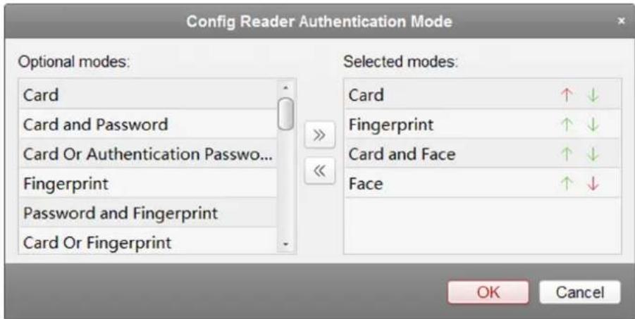
text_image
Config Reader Authentication Mode Optional modes: Card Card and Password Card Or Authentication Passwo... Fingerprint Password and Fingerprint Card Or Fingerprint Selected modes: Card Fingerprint Card and Face Face OK CancelFigure 19-2 Select Card Reader Authentication Mode
i Note
- Password refers to the card password set when issuing the card to the person. For details, refer to Add Single Person.
- Authentication password refers to the password set to open the door. Refer to Configure Authentication Password.
2) Select the modes and click to add to the selected modes list.
3) Optional: Click or to adjust the display order.
4) Click OK.
After selecting the modes, the selected modes will display as icons.
- Click the icon to select a card reader authentication mode, and drag on the day to draw a color bar on the schedule, which means in that period of time, the card reader authentication is valid.
- Repeat the above step to set other time periods.
- Optional: Select a configured day and click Copy to Week to copy the same settings to the whole week.
- Optional: Click Copy to to copy the settings to other card readers.
- Click Save.
19.7.3 Configure Multiple Authentication
You can manage the cards by group and set the authentication for multiple cards of one access control point (door).
Before You Start
Set the card permission and apply the permission settings to the access control device. For details, refer to Assign Permission to Person.
Perform this task when you want to set authentications for multiple cards of one access control point (door).
Steps
- Click Access Control → Advanced Function → Multiple Authentication to enter the Multiple Authentication page.
- Select an access control device in the list of Controller List panel.
- Add a card group for the access control device.
1) Click Add on the Set Card Group panel.
2) Create a name for the group as desired.
3) Specify the start time and end time of the effective period for the card group.
4) Select card(s) to add to the card group.
5) Click OK.
-
Select an access control point (door) of selected device on the Set Authentication Group panel.
-
Input the time interval for card swiping.
- Add an authentication group for the selected access control point.
1) Click Add on the Set Authentication Group panel.
2) Select a configured template for the authentication group from the drop-down list.
i Note
For setting the template, refer to Configure Schedule and Template.
3) Select the authentication type as Local Authentication, Local Authentication and Remotely Open Door, or Local Authentication and Super Password from the drop-down list.
Local Authentication
Authentication by the access control device.
Local Authentication and Remotely Open Door
Authentication by the access control device and by the client. When the person swipes the card on the device, a window will pop up. You can unlock the door via the client.
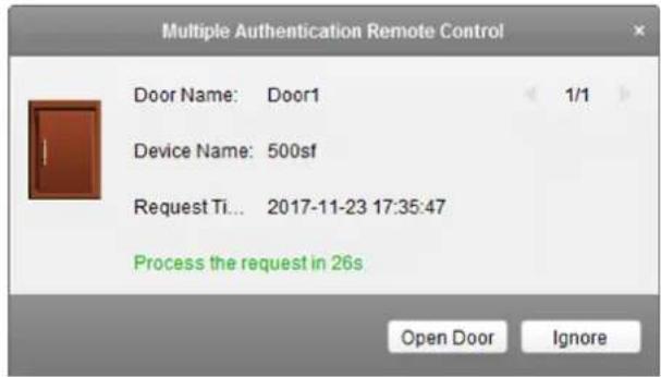
text_image
Multiple Authentication Remote Control Door Name: Door1 1/1 Device Name: 500sf Request Ti... 2017-11-23 17:35:47 Process the request in 26s Open Door IgnoreFigure 19-3 Remotely Open Door
i Note
You can check Offline Authentication to enable the super password authentication when the access control device is disconnected with the client.
Local Authentication and Super Password
Authentication by the access control device and by the super password.
4) Select the added card group in the left list below and click to add the selected card group to the right list as the authentication group.
5) Optional: Click or to set the card swiping order.
6) Click the added authentication group in the right list to set card swiping times.
i Note
- The card swiping times should be larger than 0 and smaller than the added card quantity in the card group.
- The maximum value of card swiping times is 16.
7) Click OK.
i Note
- For each access control point (door), up to four authentication groups can be added.
- For the authentication group of which authentication type is Local Authentication, up to 8 card groups can be added to the authentication group.
- For the authentication group of which authentication type is Local Authentication and Super Password or Local Authentication and Remotely Open Door, up to 7 card groups can be added to the authentication group.
7. Click Save.
19.7.4 Configure Opening Door with First Card
You can set multiple first cards for one access control point. After the first card swiping, it allows multiple persons access the door or other authentication actions.
Before You Start
Set the card permission and apply the permission setting to the access control device. For details, refer to Assign Permission to Person.
Perform this task when you want to configure opening door with first card.
Steps
- Click Access Control → Advanced Function → Open Door with First Card to enter the Open Door with First Card page.
- Select an access control device in the list of Controller List panel.
- Select the first card mode as Remain Open with First Card, Disable Remain Open with First Card, or First Card Authorization from the drop-down list for each access control point of the selected device.
Remain Open with First Card
The door remains open for the configured time duration after the first card swiping until the remain open duration ends. If you select this mode, you should set the remain open duration.

The remain open duration should be between 0 and 1440 minutes. By default, the remain open duration is 10 minutes.
Disable Remain Open with First Card
Disable the function of remaining open with first card.
First Card Authorization
All authentications (except for the authentications of super card, super password, duress card, and duress code) are allowed only after the first card authorization.

The First Card Authorization is effective only on the current day. The authorization will be expired after 24:00 on the current day.

You can swipe the first card again to disable the first card mode.
- Click Add on the First Card List panel.
- Select a card in the list and click OK to add the selected card as the first card of the doors. The added first card will list on the First Card List panel.
- Optional: Select a first card from the list and click Delete to remove the card from the first card list.
- Click Save.
19.7.5 Configure Anti-Passback
You can set to only pass the access control point according to the specified path and only one person could pass the access control point after swiping the card.
Before You Start
Enable the anti-passing back function of the access control device.
Perform this task when you want to configure the anti-passing back for the access control device.
Steps

Either the anti-passing back or multi-door interlocking function can be configured for an access control device at the same time. For the configuration of multi-door interlocking, refer to Configure Multi-door Interlocking.
- Click Access Control → Advanced Function → Anti-Passback to enter the anti-passing back configuration page.
- Select an access control device in the list.
- Select a card reader as the beginning of the path in the First Card Reader field.
- Click the text field of the selected first card reader in the Card Reader Afterward column to open Select Card Reader dialog.
- Select the afterward card readers for the first card reader.

Up to four afterward card readers can be added for one card reader.
-
Click OK in the dialog to save the selections.
-
Click Save at the upper-right corner of Anti-Passing Back page to save the settings and take effect.
Example
Set Card Swiping Path
If you select Reader In_01 as the beginning, and select Reader In_02, Reader Out_04 as the linked card readers. Then you can only get through the access control point by swiping the card in the order as Reader In_01, Reader In_02 and Reader Out_04.
19.7.6 Configure Cross-Controller Anti-passing Back
You can set anti-passing back for card readers in multiple access control devices. You should swipe the card according to the configured swiping card route. And only one person could pass the access control point after swiping the card.

Note
It should be supported by the device.
Configure Route Anti-passing Back Based on Card
The route anti-passing back depends on the card swiping route. You should set the first card reader and the card readers afterwards. It will judge the anti-passing back according to the entrance and exit records on the card.
Perform this task if you need to configure route anti-passing back and judge the anti-passing back according to the entrance and exit records on the card.
Steps

Note
It supports M1 card at present and the sector cannot be encrypted. For details about sector encryption, refers to Authenticate M1 Card Encryption.
- Click Access Control → Advanced Function → Cross-Controller Anti-passing Back to enter the cross-controller anti-passing back configuration page.
- Check Enable Cross-Controller Anti-passing Back to enable the function.
- Select Based on Card as the anti-passing back mode.
- Select Route Anti-passing Back as the rule.
- Set the sector ID.
- Click Select Access Controller to select a device for anti-passing back.

Note
Up to 64 devices with anti-passing back function can be added.
- Set the first card reader and after card readers.
1) In the Card Reader area, click the icon on the left of the card reader column to set it as the first card reader.
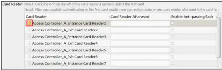
text_image
Card Reader: Note1. Click the icon on the left of the card reader's name to select the first card. Note2. After successfully authenticating on the first card reader, you can authenticate on any card reader afterward in the card re... Card Reader Card Reader Afterward Enable Anti-passing Back Access Controller_A_Entrance Card Reader1 Access Controller_A_Exit Card Reader2 Access Controller_A_Entrance Card Reader3 Access Controller_A_Exit Card Reader4 Access Controller_A_Entrance Card Reader5 Access Controller_A_Exit Card Reader6 Access Controller_A_Entrance Card Reader7Figure 19-4 Select First Card
The icon will turn to
2) Click the card reader afterward input field to select the card readers afterward in the pop-up window.
i Note
- Up to 16 card readers afterward can be added for each card reader.
- The displayed card readers in the card reader afterward input field should be in authentication order.
3) Check the checkbox in the Enable Anti-passing Back column to enable the anti-passing back function.
- Click Save.
Configure Route Anti-passing Back Based on Network
The route anti-passing back depends on the card swiping route. You should set the first card reader and the card readers afterwards. It will authenticate the anti-passing back according to the entrance and exit information stored on the card reader.
Perform this task if you need to configure route anti-passing back and authentice the anti-passing back recsult according to the entrance and exit information stored on the card reader.
Steps
- Click Access Control → Advanced Function → Cross-Controller Anti-passing Back to enter the cross-controller anti-passing back configuration page.
- Check Enable Cross-Controller Anti-passing Back to enable the function.
- Select Based on Network as the anti-passing back mode.
- Select Route Anti-passing Back as the rule.
- Select a server in the drop-down list for judging the anti-passing back.
i Note
- You can click Delete Card Swiping Record and select the card in the pop-up window to delete the card swiping information in all devices.
-
Up to 5000 cards' swiping records can be stored in the selected server.
-
Click Select Access Controller to select a device for anti-passing back.
i Note
Up to 64 devices with anti-passing back function can be added.
- Set the first card reader and after card readers.
1) In the Card Reader area, click the icon on the left of the card reader column to set it as the first card reader.
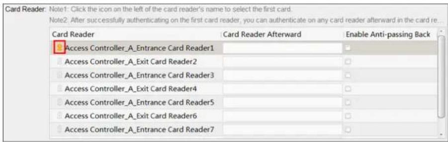
text_image
Card Reader: Note1: Click the icon on the left of the card reader's name to select the first card. Note2: After successfully authenticating on the first card reader, you can authenticate on any card reader afterward in the card re... Card Reader Card Reader Afterward Enable Anti-passing Back Access Controller_A_Entrance Card Reader1 Access Controller_A_Exit Card Reader2 Access Controller_A_Entrance Card Reader3 Access Controller_A_Exit Card Reader4 Access Controller_A_Entrance Card Reader5 Access Controller_A_Exit Card Reader6 Access Controller_A_Entrance Card Reader7 □ □ □Figure 19-5 Select First Card
The icon will turn to
2) Click the card reader afterward input field to select the card readers afterward in the pop-up window.
i Note
- Up to 16 card readers afterward can be added for each card reader.
- The displayed card readers in the card reader afterward input field should be in authentication order.
3) Check the checkbox in the Enable Anti-passing Back column to enable the anti-passing back function.
- Click Save.
Configure Entrance/Exit Anti-Passback Based on Card
You can set the entrance card reader and the exit card reader only for entering and exiting, without setting the first card reader and the card readers afterwards. It will judge the anti-passing back according to the entrance and exit records on the card.
Perform this task if you need to configure entrance/exit anti-passing back and judge the anti-passing back according to the entrance and exit records on the card.
Steps

Note
It supports M1 card at present and the sector cannot be encrypted. For details about sector encryption, refers to Authenticate M1 Card Encryption.
- Click Access Control → Advanced Function → Cross-Controller Anti-passing Back to enter the cross-controller anti-passing back configuration page.
- Check Enable Cross-Controller Anti-passing Back to enable the function.
- Select Based on Card as the anti-passing back mode.
- Select Entrance/Exit Anti-passing Back as the rule.
- Set the sector ID.
- Click Select Access Controller to select a device for anti-passing back.

Note
Up to 64 devices with anti-passing back function can be added.
- In the Card Reader area, check the checkboxes in the Enable Anti-passing Back column to select the entrance card reader and the exit card reader.

Note
Up to one entrance carder and one exit card reader should be checked.
- Click Save.
Configure Entrance/Exit Anti-Passback Based on Network
You can set the entrance card reader and the exit card reader only for entering and exiting, without setting the first card reader and the card readers afterwards. It will authenticate the anti-passing back according to the entrance and exit information on the card reader.
Perform this task if you need to configure entrance/exit anti-passing back and judge the anti-passing back according to the entrance and exit information stored on the card reader.
Steps
- Click Access Control → Advanced Function → Cross-Controller Anti-passing Back to enter the cross-controller anti-passing back configuration page.
- Check Enable Cross-Controller Anti-passing Back to enable the function.
- Select Based on Network as the anti-passing back mode.
- Select Entrance/Exit Anti-passing Back as the rule.
- Select a server in the drop-down list for judging the anti-passing back.
i Note
- You can click Delete Card Swiping Record and select the card in the pop-up window to delete the card swiping information in all devices.
-
Up to 5000 cards' swiping records can be stored in the selected server.
-
Click Select Access Controller to select a device for anti-passing back.
i Note
Up to 64 devices with anti-passing back function can be added.
- In the Card Reader area, check the checkboxes in the Enable Anti-passing Back column to select the entrance card reader and the exit card reader.
i Note
Up to one entrance carder and one exit card reader should be checked.
- Click Save.
19.7.7 Configure Multi-door Interlocking
You can set the multi-door interlocking between multiple doors of the same access control device. To open one of the doors, other doors must keep closed. That means in the interlocking combined door group, up to one door can be opened at the same time.
Perform this task when you want to realize interlocking between multiple doors.
Steps
i Note
- Multi-door Interlocking function is only supported by the access control device which has more than one access control points (doors).
-
Either the anti-passing back or multi-door interlocking function can be configured for an access control device at the same time. For the configuration of anti-passing back function, refer to Configure Anti-Passback.
-
Click Access Control → Advanced Function → Multi-door Interlocking to enter the Multi-door Interlocking page.
-
Select an access control device in the list of Controller List panel.
-
Click Add on the Multi-door Interlocking List panel to open Add Access Control Point to Interlock window.
-
Select access control point (s) from the list.
i Note
Up to four doors can be added in one multi-door interlocking combination.
- Click OK to add the selected access control point(s) for interlocking.
The configured multi-door interlocking combination will list on the Multi-door Interlocking List panel. - Optional: Select an added multi-door interlocking combination from the list and click Delete to delete the combination.
- Click Save.
19.7.8 Configure Authentication Password
You can input the authentication password on the card reader keypad to open the door after setting the authentication password.
Perform this task when you want to configure authentication password to open door.

Note
- The authentication password function should be supported by the access control device.
- Up to 500 cards with authentication password can be added to one access control device. The password should be unique and cannot be same with each other.
Steps
- Click Access Control → Advanced Function → Authentication Password to enter the authentication password configuration page.
- Select an access control device in the list of Controller List panel.
All the applied cards and persons will display on the Card List panel.

Note
For setting and applying the permissions to the device, refer to Assign Permission to Person.
- Click the field of each card in the Password column to input the authentication password.

Note
The authentication password should contain 4 to 8 digits.
- Click Save at the upper-right corner of Authentication Password page to save the settings.
The authentication password function of the card will be enabled automatically. And you can set the card reader authentication mode of access control device as Card or Authentication Password. Refer to Configure Card Reader Authentication Mode and Schedule for details.
19.7.9 Configure Relay for Elevator Controller
For elevator controller, you can manage the relationship between the floor and the relay and configure the floor's relay type.
Configure Relationship between Relay and Floor
You can assign different kinds of relays to the target floors, so that you can control the elevator according to the relationship between the relay and the floor.
Before You Start
Add the elevator controller to the client.
Perform the following steps to assign the relays to the floors.
Steps

Note
- An elevator controller can link to up to 24 distributed elevator controllers. A distributed elevator controller can link up to 16 relays.
- By default, the relay total amount is the added floor number *3 (three types of relay).
-
If you change the floor number in the door group management, all relays in the Relay Settings interface will restore to the default settings.
-
Click Access Control → Advanced Function → Elevator Settings to enter the Relay Settings page.
- Select an elevator controller on the left.
- Select an unconfigured relay in the Unconfigured Relay panel on the right.
There are three types of relay available.
Button Relay
Control the validity for buttons of each floor.


represents button relay.
Call Elevator Relay
Control to call the elevator to go to the specified floor.


represents the call elevator relay.
Auto Button Relay
Control to press the button when the user swipes card inside the elevator. The button of the floor will be pressed automatically according to the user's permission.


represents the auto button relay.
Example
Take as an example. In the number 1-2, 1 represents the distributed elevator controller number, 2 represents the relay, and the icon represents the relay type. You can change the relay type. For details, refer to Configure Relay Type.
-
Configure the relationship between the relays and the floors.
-
Drag the unconfigured relay from the Unconfigured Relay panel to the target floor in the Floor List panel.
- Drag the relay from the Floor List panel to the Unconfigured Relay panel.
- Drag the relay from one floor to another floor in the Floor List panel.

Note
If the target floor has already configured with a relay of the same type as the dragged one, it will replace the existed one of the same type.
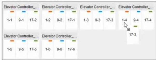
text_image
Elevator Controller_ 1-1 9-1 17-2 1-2 9-2 17-1 1-3 9-3 17-3 1-4 9-4 17-4 Elevator Controller_ 1-5 9-5 17-5 1-6 9-6 17-6 Elevator Controller_ 17-3Figure 19-6 Replace Existed Relay Type
- Click Save to apply the settings to the selected elevator controller.
Configure Relay Type
For some reasons, you should change relay types. You can change the button relay, call elevator relay, and auto button relay with each other.
Perform the following steps to change the relay type.
Steps
-
Click Access Control → Advanced Function → Elevator Settings to enter the Relay Settings page.
-
Select an elevator controller in the Controller List on the left of the page.
-
Click Relay Type to open the Relay Type Settings window.

Note
- All relays in the Relay Type Settings window are unconfigured relays.
-
Three types of relay are available: represents the button relay, represents the call elevator relay, and represents the auto button relay.
-
Drag the relay from one relay type panel to the target one.
-
Click OK.
19.7.10 Configure Custom Wiegand Rule
Based on the knowledge of uploading rule for the third party Wiegand, you can set multiple customized Wiegand rules to communicate between the device and the third party card readers.
Before You Start
Wire the third party card readers to the device.
Perform this task to configure the custom Wiegand rule for the third party card readers.
Steps

Note
- By default, the device disables the custom wiegand function. If the device enables the custom Wiegand function, all wiegand interfaces in the device will use the customized wiegand protocol.
- Up to 5 custom Wiegands can be set.
-
For details about the custom Wiegand, see Custom Wiegand Rule Descriptions.
-
Click Access Control → Advanced Function → Custom Wiegand to enter the custom Wiegand configuration page.
-
Select a custom Wiegand on the left.
-
Check Enable to enable the custom Wiegand.
-
Create a Wiegand name.

Note
Up to 32 characters are allowed in the custom Wiegand name.
-
Click Select Device to select the access control device for setting the custom wiegand.
-
Set the parity according to the property of the third party card reader.

Note
- Up to 80 bits are allowed in the total length.
- The odd parity start bit, the odd parity length, the even parity start bit and the even parity length range from 1 to 80 bit.
-
The start bit of the card ID, the manufacturer code, the site code, and the OEM should range from 1 to 80 bit.
-
Set output transformation rule.
1) Click Set Rule to open the Set Output Transformation Rules window.
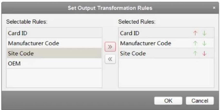
text_image
Set Output Transformation Rules Selectable Rules: Card ID Manufacturer Code Site Code OEM Selected Rules: Card ID ↑ ↓ Manufacturer Code ↑ ↓ Site Code ↑ ↓ OK CancelFigure 19-7 Set Output Transformation Rule
2) Select rules on the left list.
3) Click to move the selected rules to the right list.
4) Optional: Click or to change the rule order.
5) Click OK.
6) In the Custom Wiegand tab, set the rule's start bit, length, and the decimal digit.
- Click Save.
19.7.11 Configure Person in Blacklist
You can manage the person information in the blacklist and apply the blacklist information to the access control device to take effect.
Add Person to Blacklist
You can add persons to the blacklist, and configure the person's face pictures, gender, and ID number.
Perform this task when you need to configure person information in blacklist for access control device.
Steps
-
Click Access Control → Advanced Function → Blacklist to enter the person in blacklist management page.
-
Click Person to enter the person management page.
-
Click Add.
-
Click Select Picture to select a face picture for the person from local PC.

The picture should be in JPG format and it should be smaller than 1 MB.
-
Set the person details including name, gender, and ID number.
-
Click Save.
-
Optional: Select the added person and click Delete to remove it from the blacklist.
-
Apply the person information in blacklist to the device to take effect.
1) Select the person(s) to apply to the device.
2) Click Apply.
3) Select Apply All to start applying all the selected permission(s) to the access control device or door station.

You can also select Apply Changes to apply the changed part of the selected permission(s) to the device(s).
4) Click OK to start applying.
Manage Application Result of Person in Blacklist
After applying the configured person information in blacklist, you can view the application results and manage the applied person.
Perform this task when you need to manage the person information application result of blacklist.
Steps
-
Click Access Control → Advanced Function → Blacklist to enter the person in blacklist management page.
-
Click Application Result to enter the application result management page.
You can check the person in blacklist applying record and view the application results.
- Optional: Remove the applied person in blacklist from device.
1) Click Delete Person.
All the devices which support person in blacklist will display.
2) Select the device that you want to remove person(s) from.
3) Click Next.
All the persons in blacklist applied to the device will display.
4) Select the person(s) you want to remove from the device.
5) Click OK to remove the selected person from the blacklist of the device.
- Optional: Click Clear Persons and select the device to clear all the persons in the blacklist of the device.
19.8 Search Access Control Event
You can search the access control history events including remote event and local event via the client.
19.8.1 Search Access Control Events Stored in Local Client
You can search the history access records and events from the database of the current client and export the records to local PC.
Steps
i Note
You can search the access control events within three months.
- Click Access Control → Search → Access Control Event to enter the searching access control event page.
- Select the event source as Local Event.
- Set the search conditions, such as device(s), event type, occurred time, and so on.
- Click Search to start searching the access control events.
The matched access control events will display.
- Optional: After searching the events, you can do one or more of the followings.
| View Person Details | For the access control event which is triggered by person, click the event to view the person details, including person No., person name, organization, phone number, contact address and photo. |
| View Captured Picture | For events contain linked pictures, clickCapturecolumn to view the captured picture of the triggered camera when the alarm is triggered. |
| NoteFor setting the triggered camera, refer toConfigure Client Linkage for Access Control Alarm . | |
| View Linked Video | For events contain linked video, clickPlaybackcolumn to view the recorded video file of the triggered camera when the alarm is triggered. |
| NoteFor setting the triggered camera, refer toConfigure Client Linkage for Access Control Alarm . | |
| Export Event Information | Click Exportto export the search results to the local PC in CSV file. |
19.8.2 Search Access Control Events Stored on Device
You can search the access control event records stored on the access control device.
Steps
- Click Access Control → Search → Access Control Event to enter the searching remote access control event page.
- Select the event source as Remote Event.
- Set the search conditions as deiaired.
- Optional: Check With Alarm Picture to search the events with alarm pictures.
- Click Search.
The matched access control events will display. - Optional: Click Export to export the search results to the local PC in CSV file.
19.9 Configure Access Control Alarm Linkage
For the added access control device, you can configure the linkage actions such as client linkage, device linkage, or cross-device linkage.
19.9.1 Configure Client Linkage for Access Control Alarm
You can assign client linkage actions to the access control alarm by setting up a rule. For example, when the access control event is detected, an audible warning appears or other linkage actions happen.
Perform this task when you need to configure the client linkage for the access control alarm.
Steps

Note
The linkage here refers to the linkage of the client software's own actions such as pop-up image, audible warning, email linkage, etc.
- Click Event Management → Access Control Event.
The added access control devices will display in the Access Control Device panel on the left.
-
Select the access control device, or alarm input, or access control point (door), or card reader to configure the event linkage.
-
Select the event type to set the linkage.
-
Select the triggered camera.

Note
To capture the picture of the triggered camera when the selected event occurs, you can also set the capture schedule and the storage in Storage Schedule. For details, refer to Remote Storage Configuration.
The image or video from the triggered camera will pop up when the selected event occurs.
- Set the client linkage actions.
Audible Warning
The client software gives an audible warning when alarm is triggered. You can select the alarm sound for audible warning.

For setting the alarm sound, please refer to Set Alarm Sound.
Email Linkage
Send an email notification of the alarm information to one or more receivers.
Alarm on E-map
Display the alarm information on the E-map.

This linkage is only available to access control point and alarm input.
Alarm Triggered Pop-up Image
The image with alarm information pops up when alarm is triggered.

You should set the triggered camera first.
6. Click Save.
- Optional: Click Copy to copy the linkage settings to other access control device, alarm input, access control point, or card reader.
19.9.2 Configure Device Linkage for Access Control Alarm
You can set the access control device's linkage actions for the access control device's triggered alarm. When the alarm is triggered, it can trigger the alarm output, host buzzer, and other actions on the same device.
Perform this task when you need to configure the access control device linkage for the device's access control alarm.
Steps

It should be supported by the device.
- Click Event Management → Event Card Linkage.
- Select the access control device from the list on the left.
- Click Add button to add a new linkage.
- Select the event source as Event Linkage.
-
select the alarm type and detailed alarm to set the linkage.
-
In the Linkage Target panel, set the property switch to on to enable this action.
Host Buzzer
The audible warning of access control device will be triggered.
Capture
The real-time capture will be triggered.
Recording
The recording will be triggered.

The device should support recording.
Card Reader Buzzer
The audible warning of card reader will be triggered.
Alarm Output
The alarm output will be triggered for notification.
Zone
Arm or disarm the zone.

The device should support zone function.
Access Control Point
The door status of open, close, remain open, and remain close will be triggered.

- The door status of open, close, remain open, and remain close cannot be triggered at the same time.
- The target door and the source door cannot be the same one.
Audio Play
The audio prompt will be triggered. And the select audio index related audio content will be played according to the configured play mode.
7. Click Save.
- Optional: After adding the device linkage, you can do one or more of the following:
Edit Linkage
Settings
Delete Linkage
Settings
Select the configured linkage settings in the device list and you can edit its event source parameters, including event source and linkage target.
Select the configured linkage settings in the device list and click Delete to delete it.
19.9.3 Configure Device Linked Actions for Card Swiping
You can set the access control device's linkage actions for the specified card swiping. When you swipe the specified card, it can trigger the alarm output, host buzzer, and other actions on the same device.
Perform this task when you need to configure the access control device linkage for the card swiping action.
Steps

Note
It should be supported by the device.
- Click Event Management → Event Card Linkage.
- Select the access control device from the list on the left.
- Click Add button to add a new linkage.
- Select the event source as Card Linkage.
- Input the card number or select the card from the dropdown list.
- Select the card reader where the card swipes to trigger the linked actions.
- In the Linkage Target panel, set the property switch to on to enable this action.
Host Buzzer
The audible warning of access control device will be triggered.
Capture
The real-time capture will be triggered.
Recording
The recording will be triggered.

The device should support recording.
Card Reader Buzzer
The audible warning of card reader will be triggered.
Alarm Output
The alarm output will be triggered for notification.
Zone
Arm or disarm the zone.

The device should support zone function.
Access Control Point
The door status of open, close, remain open, and remain close will be triggered.
i Note
The door status of open, close, remain open, and remain close cannot be triggered at the same time.
Audio Play
The audio prompt will be triggered. And the select audio index related audio content will be played according to the configured play mode.
8. Click Save.
When the card (configured in Step 5) swipes on the card reader (configured in Step 6), it can trigger the linked actions (configured in step 7).
- Optional: After adding the device linkage, you can do one or more of the following:
| Delete Linkage Settings | Select the configured linkage settings in the device list and click Delete to delete it. |
| Edit Linkage Settings | Select the configured linkage settings in the device list and you can edit its event source parameters, including event source and linkage target. |
19.9.4 Configure Device Linkage for Mobile Terminal's MAC Address
You can set the access control device's linkage actions for the specified MAC address of mobile terminal. When the access control device detects the specified MAC address, it can trigger the alarm output, host buzzer, and other actions on the same device.
Perform this task when you need to configure the access control device linkage for the MAC address
Steps
i Note
It should be supported by the device.
-
Click Event Management → Event Card Linkage.
-
Select the access control device from the list on the left.
-
Click Add button to add a new linkage.
-
Select the event source as MAC Linkage.
-
Input the MAC address to be triggered.
i Note
MAC Address Format: AA:BB:CC:DD:EE:FF.
- In the Linkage Target panel, set the property switch to on to enable this action.
Host Buzzer
The audible warning of access control device will be triggered.
Capture
The real-time capture will be triggered.
Recording
The recording will be triggered.

The device should support recording.
Card Reader Buzzer
The audible warning of card reader will be triggered.
Alarm Output
The alarm output will be triggered for notification.
Zone
Arm or disarm the zone.

The device should support zone function.
Access Control Point
The door status of open, close, remain open, and remain close will be triggered.

The door status of open, close, remain open, and remain close cannot be triggered at the same time.
-
Click Save to save the settings.
-
Optional: After adding the device linkage, you can do one or more of the following:
| Edit Linkage Settings | Select the configured linkage settings in the device list and you can edit its event source parameters, including event source and linkage target. |
| Delete Linkage Settings | Select the configured linkage settings in the device list and click Delete to delete it. |
19.9.5 Configure Cross-Device Linkage
You can assign to trigger other access control device's action by setting up a rule when the access control event is triggered.

It should be supported by the device.
Configure Cross-Device Linkage for Access Control Event
When the access control event is triggered and detected, it can trigger linkage actions of other access control device, such as alarm output, opening door, etc. The event can be divided into four types: device event, alarm input, door event, and card reader event.
Perform this task when you need to configure other access control device's linkage actions for access control event.
Steps

Note
The devices should support this function.
- Click Event Management → Cross-Device Linkage to enter the cross-device linkage configuration interface.
- Click Add to add a new cross-device linkage.
- Select the linkage type as Event Linkage.
- Set the event source.
1) Select the access control device as event source device.
2) Select the access control event type.
Device Event
Select the detailed event type from the dropdown list.
Alarm Input
Select the detailed event type as zone event or alarm input event and select the zone name or alarm input name from the dropdown list.
Door Event
Select the detailed event type and select the access control point from the dropdown list.
Card Reader Event
Select the detailed event type and select the card reader from the dropdown list.
- Set the target access control device as linkage target.
1) Select the access control device from the dropdown list as the linkage target.
2) Set the switch to on to enable the linkage action.
Alarm Output
The alarm output pf the target device will be triggered for notification.
Access Control Point
The door status of open, close, remain open, and remain close will be triggered.

The door status of open, close, remain open, and remain close cannot be triggered at the same time.
6. Click Save.
Configure Cross-Device Linkage for Card Swiping
When person swipes the specified card on the specified card reader, it can trigger linkage actions of other access control device, such as alarm output, opening door, etc.
Perform this task when you need to configure other access control device's linkage actions for card swiping.
Steps
- Click Event Management → Cross-Device Linkage to enter the cross-device linkage configuration interface.
- Click Add to add a new cross-device linkage.
- Select the linkage type as Card Linkage.
- Set the event source.
1) Select the card from the dropdown list.
2) Select the access control device as event source device.
3) Select the card reader for triggering.
- Set the target access control device as linkage target.
1) Select the access control device from the dropdown list as the linkage target.
2) Set the switch to on to enable the linkage action.
Alarm Output
The alarm output pf the target device will be triggered for notification.
Access Control Point
The door status of open, close, remain open, and remain close will be triggered.

The door status of open, close, remain open, and remain close cannot be triggered at the same time.
6. Click Save.
19.10 Manage Access Control Point Status
The access control point status of the added access control device will be displayed in real time. You can check its status and view the access records on the selected access control points. You can also open/close the door, or remain the door open/closed via the client remotely.
19.10.1 Group Access Control Points
Before controlling the doors status and setting the status duration, you should organize the access control device's access control points into groups for convenient management.
Perform this task when you need to group the access control points for convenient management.
Steps

Note
- You can also import the access control device's alarm inputs into groups.
- For video access control terminal, you can import its camera into groups.
-
For other detailed operations, refer to Group Management.
-
Click Device Management → Group to enter the group management page.
-
Add a new group.
1) Click 📋 to open the Add Group window.
2) Create a group name.
3) Optional: Check Create Group by Device Name to create the new group by the name of the selected device.
4) Click OK.
- Import the access control points to the group.
1) Click Import.
2) Click Access Control Point tab.
3) Select the access control points in the list.
4) Select a group from the group list.
5) Click Import to import the selected access control points to the group.
19.10.2 Control Door Status
You can control the status for a single door, including opening door, closing door, remaining the door open, and remaining the door closed.
Steps
- Click Status Monitor to enter the door status monitoring page.
- Select an access control group on the left.

Note
For managing the access control group, refer to Group Access Control Points.
The access control points in the selected access control group will be displayed on the right.
-
Click to select a door.
-
Click the following buttons to control the door.
Open Door
When the door is locked, unlock it and it will be open for once. After the open duration, the door will be closed and locked again automatically.
Close Door
When the door is unlocked, lock it and it will be closed. The person who has the access permission can access the door with credentials.
Remain Open
The door will be unlocked (no matter closed or open). All the persons can access the access point with no credentials required.
Remain Closed
The door will be closed and locked. No person can access the door even if he/she has the authorized credentials, except the super users.
Capture
Capture a picture manually

The Capture button is available when the device supports capture function. The picture is saved in the PC running the client. For setting the saving path, refer to Set File Saving Path.
19.10.3 Control Elevator Status
You can control the elevator status for elevator controller, including opening elevator's door, controlled, free, calling elevator, etc.
Before You Start
Before controlling the elevator status, you should distribute the relays to the targetfloors. For details, refer to Configure Relationship between Relay and Floor.
Steps
i Note
- You can control the elevator via the current client if it is not armed by other client. The elevator cannot be controlled by other client software if the elevator status changes.
- Only one client software can control the elevator at one time.
-
The client which has controlled the elevator can receive the alarm information and view the elevator real-time status.
-
Click Status Monitor to enter the door status monitoring page.
-
Select an access control group on the upper-left corner.

For managing the access control group, refer to Group Access Control Points.
The floors of the selected access control group will be displayed on the right of the interface.
-
Click to select a floor.
-
Click the following buttons to control the floor.
Open Door
The floor's button in the elevator will be valid for a period of time and the elevator's door is open.
Controlled
You should swipe the card before pressing the target floor button. And the elevator can go to the target floor.
Free
The selected floor's button in the elevator will be valid all the time.
Disabled
The selected floor's button in the elevator will be invalid and you cannot go to the target floor.
Call Elevator (Visitor)
The elevator will go down to the first floor. The visitor can only press the target floor's button.
Call Elevator (Resident)
Call the elevator to the target floor.
19.10.4 Check Real-time Access Records
The access records will display in real time, including card swiping records, face recognitions records, fingerprint comparison records, etc. You can view the person information and view the picture and video captured and recorded during access.
Steps
- Click Status Monitor and select a group from the drop-down list.
The access records of the access control points in the selected group will display in realtime. You can view the details of the records, including card No., person name, organization, event time, etc.
-
Optional: Check Show Latest Access Record and the latest access record will be selected and displayed at the top of the record list.
-
Optional: Click the event to view the accessed person details, including person pictures (captured picture and profile) and video, person No., person name, organization, phone, contact address, etc.
Authentication Result
Access results such as card No. not registered, succeeded, etc.
- Optional: Right click on the column name of the access record table to show or hide the column according to actual needs.
19.11 Control Door during Live View
During live view, you can control the camera's linked access control point (door) such as opening door, closing door, etc.
Perform this task when you need to control the camera's linked door to open or close during live view.
Steps
- Enter Live View module and start live view of one camera.

For details about starting live view, refer to Start Live View for One Camera for details.
- Link the camera with an access control point.
1) Right click on the live view window and select Link to Access Control Point to open the Set Linked Access Control Point window.
2) Check Enable to enable the linkage.
3) Select access control point from the drop-down list.
4) Click OK.

One camera can be linked to only one access control point; Different cameras can be linked to the same access control point.
- Start the camera's live view again to make the settings effective.
Four door control buttons will appear on the toolbar during live view.
- Click to control the door to open, close, remain open, or remain closed.
19.12 Display Access Control Point on E-map
You can add the access control point on the E-map. When the alarm of the access control point is triggered, you can view the alarm notification on the E-map, check the alarm details, and control the door.
Perform this task when you need to display the access control point on the e-map as hot spot.
Steps

- For Video Access Control Terminal, you can also add its camera to the E-map to view the live view of the camera.
-
For detailed operations of E-map, refer to Map Management.
-
Enter E-map module.
-
Click Edit on the E-map toolbar to enter the map editing mode.
- Click on the toolbar to open the Add Hot Spot window.
- Select the access control point to be added as hot spot.
- Optional: Edit hot spot name, select the name color, and select the hot spot icon by double-clicking the corresponding field.
- Click OK.
The door icons are added on the map as hot spots and the icons of added access control points change from ■ to ■ in the group list. You can click-and-drag the access control point icons to move the hot spots to the desired locations.
- After adding the access control point on the map as hot spot, you can control the access control point and view triggered alarm.
1) Click Exit Editing Mode on the E-map toolbar to enter the map preview mode.
2) To control the access control point, you can right click the access control point icon on the map, and click Open Door, Close Door, Remain Open, and Remain Closed to control the door.
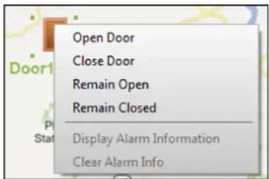
text_image
Open Door Close Door Remain Open Remain Closed Display Alarm Information Clear Alarm InfoFigure 19-8 Control Access Control Point on Map
3) Optional: If there is any alarm triggered, an icon 📋 will appear and twinkle near the hot spot (it will twinkle for 10s). Click the alarm icon to check the alarm information, including alarm type and triggering time.

To display the alarm information on the map, you should set display on e-map as the alarm linkage action. For details, refer to Configure Client Linkage for Access Control Alarm.
19.13 Two-way Audio
Two-way audio function enables the voice talk between the client and devices. After adding the device to the client software, you can call the client from the device or call the device from the client. You can get not only the live video but also the real-time audio.
19.13.1 Call Client from the Device
For the access control devices with the camera, you can call the client via the device. If the requirement is accepted, you can get the real-time audio and video from the client.
Before You Start
Add the device to the software and properly configure the corresponding settings. See Add Device for details about adding the device.
Perform this task if you need to receive the call from the access control device.
Steps

Note
This function should be supported by the device.
- Tap Call on the device initial page.
- Enter 0 in the pop-up window.
- Tap Call to call the client.
- Click Answer on the pop-up page of the client to answer the call.
An incoming call dialog appears in the client software. You can start two-way audio between the device and the client.

Note
If the device is added by multiple clients and when the device is calling the client, only the first client added the device will show the call receiving window.
19.13.2 Call Device from Client
You can call the added access control device with the camera via the client and perform two-way audio.
Before You Start
Add the device to the software and properly configure the corresponding settings. See Add Device for details about adding the device.
Perform this task if you want to call the access control device via the client.
Steps

Note
This function should be supported by the device.
- Enter the Main View page.
- Start the live view of the device's camera.
- Right-click the live view window to open the shortcut menu.
- Click Start Two-Way Audio.
The call will be answered automatically to start two-way audio between the device and the client.
Chapter 20 Time and Attendance
The Time and Attendance module provides multiple functionalities to track and monitor when employees start and stop work, and full control of employees working hours such as late arrivals, early departures, time taken on breaks and absenteeism.

Note
In this section, we introduce the configurations before you can getting the attendance reports. The access records recorded after these configurations will be calculated in the statistics.
20.1 Manage Shift Schedule
Shift work is an employment practice designed to make use of all 24 hours of the clock each day of the week. The practice typically sees the day divided into shifts, set periods of time during which different shifts perform their duties.
You can set department schedule, person schedule, and temporary schedule.
20.1.1 Add Time Period
You can add the time period for the shift schedule.
Perform this task when you need to add time period.
Steps
- Enter Time and Attendance module and click Shift Schedule Management tab.
- Click Shift Settings → Time Period Settings to enter Time Period Settings window.
- Click Add to enter Add Time Period page.
- Set the time period related parameters.
Attend at Least
Set the minimum attendance time.

If you have configured the different card readers as start-work and end-work check points, you can check Absence time is not included in effective work hours to exclude the absence time from the work hours.
Check-in / Check-out Required
Check the checkboxes and set the valid period for check-in or check-out.
Mark as Late/Mark as Early Leave
Set the time period for late or early leave.
Exclude Break Period from Work Duration
Check the checkbox and set the break period excluded.

Up to 3 break periods can be set.
Set as Pay-per-Time Period
Check the checkbox and set the pay rate and minimum time unit.
5. Click Save.
The added time period lists on the left panel of the window.
20.1.2 Add Shift
You can add the shift for the shift schedule.
Before You Start
Add a time period first. See Add Time Period for details.
Perform this task when you need to add shift.
Steps
- Enter Time and Attendance module.
- Click Shift Schedule Management → Shift Settings → Shift to enter Shift Settings window.
- Click Add to enter Add Shift page.
- Input the name for shift.
- Select the shift period from the drop-down list.
- Select the added time period and click on the time bar to apply the time period.
- Click Save.
The added shift lists on the left panel of the window.
20.1.3 Set Department Schedule
You can set the shift schedule for one department, and all the persons in the department will be assigned with the shift schedule.
Before You Start
In Time and Attendance module, the department list is the same with the organization in Access Control module. You should add departments and persons in Access Control module first. See Manage Organization and Manage Person Information for details.
Perform this task when you need to set department schedule.
Steps
-
Click Time and Attendance → Shift Schedule Management to enter the Shift Schedule Management page..
-
Select a department and click Department Schedule to pop up Department Schedule window.
- Check Time and Attendance.
All persons in the department expect those excluded from attendance will apply the attendance schedule.
- Select the shift from the drop-down list.
- Set the start date and end date.
- Set other parameters for the schedule, including Check-in Not Required, Check-out Not Required, Effective for Holiday, Effective for Overtime, or Effective for Multiple Shift Schedules.
i Note
After checking the Effective for Multiple Shift Schedules, you can select the effective time period(s) from the added time periods for the persons in the department.
Multiple Shift Schedules
It contains more than one time periods. The person can check in/out in any of the time periods and the attendance will be effective.
If the multiple shift schedules contains three time periods: 00:00 to 07:00, 08:00 to 15:00 and 16:00 to 23:00. The attendance of the person adopting this multiple shift schedules will be effective in any of the three time periods. If the person checks in at 07:50, it will apply the nearest time period 08:00 to 15:00 to the person's attendance.
- Optional: Check Set as Default for All Persons in Department.
All persons in the department will use this shift schedule by default.
- Optional: If the selected department contains sub department(s), you can check Set as Shift Schedule for All Sub Departments to apply the department schedule to its sub departments.
- Click Save.
20.1.4 Set Person Schedule
You can assign the shift schedule to one person. You can also view and export the person schedule details.
Before You Start
Add department and person in Access Control module. See Manage Organization and Manage Person Information for details.
Perform this task when you need to set person schedule.
Steps
- Enter Time and Attendance module.
- Click Shift Schedule Management to enter the Shift Schedule Management page.
- Select the department and select one person.
- Click Person Schedule to pop up Person Schedule window.
- Check Time and Attendance.
The configured person will apply the attendance schedule.
- Select the shift from the drop-down list.
- Set the start date and end date.
- Set other parameters for the schedule, including Check-in Not Required, Check-out Not Required, Effective for Holiday, Effective for Overtime, and Effective for Multiple Shift Schedules.

After checking the Effective for Multiple Shift Schedules, you can select the effective time period(s) from the added time periods for the persons in the department.
Multiple Shift Schedules
It contains more than one time periods. The person can check in/out in any of the time periods and the attendance will be effective. If the multiple shift schedules contains three time periods: 00:00 to 07:00, 08:00 to 15:00 and 16:00 to 23:00. The attendance of the person adopting this multiple shift schedules will be effective in any of the three time periods. If the person checks in at 07:50, it will apply the nearest time period 08:00 to 15:00 to the person's attendance.
9. Click Save.
20.1.5 Set Temporary Schedule
You can add a temporary schedule for the person and the person will be assigned with the shift schedule temporarily. You can also view and export the temporary schedule details.
Before You Start
Add department and person in Access Control module, and set the attendance rule for the person. See Manage Organization and Manage Person Information for details.
Perform this task when you need to set temporary schedule.
Steps

The temporary schedule has higher priority than department schedule and person schedule.
- Enter Time and Attendance module.
- Click Shift Schedule Management tab to enter the Shift Schedule Management page.
- Select the department and select one person.
- Click Temporary Schedule to pop up Temporary Schedule window.
- Click to set the shift date.
- Select the time period.
- Click the time bar to apply the time period for the select date.
- Optional: Click Advanced Settings and select advanced attendance rules for the temporary schedule.
- Click Add.
20.1.6 Check and Edit Shift Schedule
You can check the shift schedule details and edit the schedule.
Perform this task when you need to check and edit shift schedule.
Steps
- Enter Time and Attendance module.
- Click Shift Schedule Management tab to enter the Shift Schedule Management page.
- Select the department and corresponding person(s).
-
Click View to open Shift Schedule Details window.
The shift schedule details display. -
Edit the normal schedule details.
1) Click Normal Schedule tab.
2) Select a shift from the drop-down list.
3) Click Attendance Rule Settings to open Attendance Rule Settings window.
4) Select the attendance rules as desired and click OK.
5) Click to set the effective date.
6) Click Save.
- Optional: Click Temporary Schedule and perform one of the following operations.
Add Add the temporary schedule for the selected person.
Edit the time period.
✗ Delete the temporary schedule.
20.2 Manually Correct Check-in/out Record
If the attendance status is not correct, you can manually correct the check-in or check out record. You can also edit, delete, search, or export the check-in or check-out record.
Before You Start
- You should add organizations and persons in Access Control module. For details, refer to Manage Organization and Manage Person Information.
- The person's attendance status is incorrect.
Perform the following steps to correct the check-in or check-out record.
Steps
- Enter Time and Attendance module.
- Click Attendance Handling → Check-in/out Correction to enter the Check-in/out Correction page.
- Click Add to enter the Add Check-in/out Correction window.
- Set the check-in/out correction parameters.
- Check Check-in and set the actual start-work time.
- Check Check-out and set the actual end-work time.
- Click Employee Name field and select the person for correction.
- Optional: Input the remark information as desired.
- Click Add.
- Optional: After adding the check-in/out correction, perform one of the following operations.
Search Set the search conditions and search the correction.
Modify Edit the selected check-in/out correction.
Delete Delete the selected check-in/out correction.
Report Generate and view the check-in/out correction report.
Export Export the check-in/out correction details to local PC.

The exported details are saved in CSV format.
20.3 Add Leave and Business Trip
You can add leave and business trip application when the employee want to ask for leave or go on a business trip.
Before You Start
You should add organizations and persons in the Access Control module. For details, refer to Manage Organization and Manage Person Information.
Perform the following steps when you want to add a leave or business trip application.
Steps
- Enter Time and Attendance module.
- Click Attendance Handling → Leave and Business Trip to enter the Leave and Business Trip page.
- Click Add to open the Add Leave and Business Trip Application window.
- Select the leave and business trip type from the drop-down list.

You can set the leave type in Advanced Settings. For details, refer to Configure Leave Type.
- Click and set the time period for your leave or business trip.
- Click Employee Name filed and select the person for the application in the pop-up Add Person window.
- Optional: Input the remark information as desired.
- Click Add.
The added leave and business trip displays on the Leave and Business Trip page.
- Optional: After adding the leave and business trip application, perform one of the following operations.
Modify Select the leave and business trip and click Modify to edit the leave or business application.
Delete Select the leave and business trip and click Delete to delete the leave or business trip application.
Report Click Report to generate the leave or business trip report.
Export Click Export to export the leave or business trip details to local PC.

The exported details are saved in CSV format.
20.4 Calculate Attendance Data
You need to calculate the attendance data before searching and viewing the overview of the attendance data, employees' detailed attendance data, employees' abnormal attendance data, the employees' overtime working data, and card swiping log.
20.4.1 Automatically Calculate Attendance Data
You can set a schedule so that the client can calculate the attendance data automatically at the time you configured every day.
Perform this task if you need to set the time to make the client calculate attendance data automatically.
Steps

It will calculate the attendance data till the previous day.
- Enter the Time and Attendance module.
- Click Attendance Handling → Attendance Calculation to enter the attendance record calculation page.
- In the Auto-Calculate Attendance panel, set the time that you want the client to calculate the data every day.
- Click Save.
20.4.2 Manually Calculate Attendance Data
You can calculate the attendance data manually by setting the data range.
Steps
-
Enter the Time and Attendance module.
-
Click Attendance Statistics.
-
In the Manually Calculate Attendance panel, set the start time and end time to define the attendance data range.
-
Click Calculate.

Note
It can only calculate the attendance data within three months.
20.5 Configure Advanced Settings
You can configure the advanced settings for the attendance, including the attendance basic settings, attendance rule settings, attendance check point settings, holiday settings, and leave type settings.
20.5.1 Configure Basic Parameters
You can configure the attendance basic parameters, including the start day of each week, the start date of each month, and the non-work day.
Perform the following steps to configure the attendance basic parameters.
Steps
-
Enter Time and Attendance module.
-
Click Advanced Settings → Basic Settings to enter the Basic Settings page.
-
Set the start day of each week and the start date of each month from the drop-down list.
-
Set the non-work day settings.
Set as Non-Work Day
Check the checkboxes to set the dates as non-work days.
Set Non-Work Day's Color in Report
Select the color from the Select Color window. The non-work days in the report will mark as the configured color.
Set Non-Work Day's Mark in Report
Input the mark and the non-work day field in the report will display with the mark.
-
Set the authentication type, which means the client will calculate the attendance data recorded based on the selected authentication type.
-
Click Save.
20.5.2 Configure Attendance Rule
You can configure the attendance rule for all shifts before setting shift. You can configure the rule for attendance/absence, check-in/out, and overtime.
Perform the following steps to configure the attendance rule.
Steps
i Note
The parameters configured here will be set as default for the newly added time period. It will not affect the existed one(s).
- Enter Time and Attendance module.
- Click Advanced Settings → Attendance Rule Settings to enter the Attendance Rule Settings page.
- Set rule parameters, including attendance/absence parameters, check-in/out parameters, and overtime parameters.
- Optional: Check Non-scheduled Work Day and set the overtime rule for non-work day.
- Click Save.
20.5.3 Configure Attendance Check Point
You can set the card reader(s) of the access control point as the attendance check point, so that the card swiping on the card reader(s) will be valid for attendance.
Before You Start
You should add access control device beforeconfiguring attendance check point. For details, refer to Add Device.
Perform the following steps to set the card reader of the access control point as the attendance check point.
Steps
i Note
By default, all card readers of the added access control devices are set as attendance checkpoint.
- Enter the Time and Attendance module.
- Click Advanced Settings → Attendance Check Point Settings to enter the Attendance Check Point Settings page.
- Optional: Uncheck Set All Card Readers as Check Points.
Only the card readers in the list will be set as the attendance check points. -
Click to enter the Add Attendance Check Point window.
-
Set the related parameters.
Check Point Name
Customize a name for the check point.
Card Reader
Select the card reader from the drop-down list as the attendance check point.
Check Point Function
Select the check point function from the drop-down list. You can set the check point as Start/End-Work check point, Start-Work check point, or End-Work check point.
Door Location
Input the door location's name.
Check Point Description
Input the check point's descriptions as desired.
- Click Add.
The added attendance check point displays on the list.
- Optional: After adding the attendance check point, perform one of the following operations.
Edit the attendance check point information.
✗ Delete the attendance check point in the list.
20.5.4 Configure Holiday
You can add the holiday during which the check-in or check-out function will be invalid.
Add Holiday with Fixed Date
You can configure a holiday which will take effect for only once.
Perform this task if you want to configure a holiday with fixed date.
Steps
- Enter the Time and Attendance module.
- Click Advanced Settings → Holiday Settings to enter the Holiday Settings page.
- Click + to pop up the Add Holiday window.
- Click Fixed Date tab.
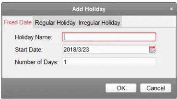
text_image
Add Holiday Fixed Date Regular Holiday Irregular Holiday Holiday Name: Start Date: 2018/3/23 Number of Days: 1 OK CancelFigure 20-1 Add Holiday with Fixed Date
- Customize a name for the holiday.
- Set the start date as the first day of the holiday.
- Set the number of days in the holiday.
- Optional: After adding the holiday, perform one of the following operations.
Edit the holiday information.
✗ Delete the holiday from the holiday list.
Add Regular Holiday
You can configure a holiday which will take effect annually on regular days during the effective period, such as New Year's Day, Independence Day, Christmas Day, etc.
Perform this task if you need to add a regular holiday.
Steps
- Enter the Time and Attendance module.
- Click Advanced Settings → Holiday Settings to enter the Holiday Settings page.
- Click to pop up the Add Holiday window.
- Click Regular Holiday tab.
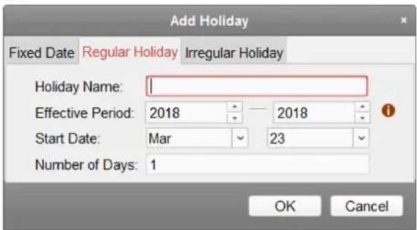
text_image
Add Holiday Fixed Date Regular Holiday Irregular Holiday Holiday Name: Effective Period: 2018 2018 Start Date: Mar 23 Number of Days: 1 OK CancelFigure 20-2 Add Regular Holiday
- Set the holiday parameters.
Start Date
The first day of the holiday.
Effective Period
The years during which the holiday's start date will take effect. For example, if the holiday's effective period is set as 2018 to 2019, and the start date is set as December 31st, and the numbers of days is 3, then the holiday will be 2018/12/31 to 2019/01/02, 2019/12/31 to 2020/01/02.
-
Click OK.
-
Optional: After adding the holiday, perform one of the following operations.
Edit the holiday information.
✗ Delete the holiday from the holiday list.
Add Irregular Holiday
You can configure a holiday which will take effect annually on irregular days during the effective period, such as Bank Holiday.
Perform this task if you want to add an irregular holiday.
Steps
- Enter the Time and Attendance module.
- Click Advanced Settings → Holiday Settings to enter the Holiday Settings page.
- Click to pop up the Add Holiday window.
- Click Irregular Holiday tab.
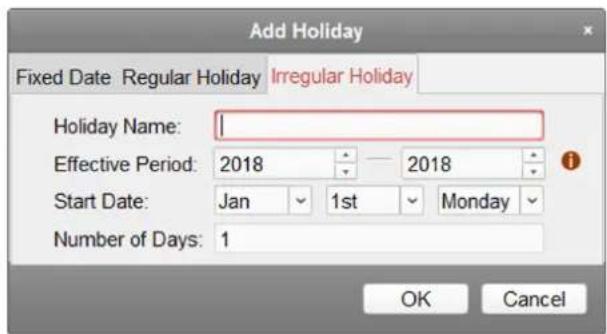
text_image
Add Holiday Fixed Date Regular Holiday Irregular Holiday Holiday Name: Effective Period: 2018 — 2018 Start Date: Jan 1st Monday Number of Days: 1 OK CancelFigure 20-3 Add Irregular Holiday
- Set the holiday parameters.
Start Date
The first day of the holiday.
Effective Period
The years during which the holiday's start date will take effect. For example, if the holiday's effective period is set as 2018 to 2019, and the start date is set as December 31st, and the
numbers of days is 3, then the holiday will be 2018/12/31 to 2019/01/02, 2019/12/31 to 2020/01/02.

If one holiday crosses two years and the effective period
-
Click OK.
-
Optional: After adding the holiday, perform one of the following operations.
Edit the holiday information.
✗ Delete the holiday from the holiday list.
20.5.5 Configure Leave Type
You can customize the leave type according to actual needs. By default, there are three major leave types: Leave, Day Off in Lieu, and Go Out on Business.
Perform the following steps to add, edit, or delete the leave type.
Steps
-
Enter the Time and Attendance module.
-
Click Advanced Settings → Leave Type Settings to enter the Leave Type Settings page.
-
Click + to add a major leave type on the left panel.
-
Optional: Perform one of the following operations for major leave type.
Edit the major leave type.
✗ Delete the major leave type.
-
Click to add a minor leave type on the right panel.
-
Optional: Perform one of the following operations for major leave type.
Edit the minor leave type.
✗ Delete the minor leave type.
20.6 View Attendance Report
After calculating attendance data, you can check the attendance summary, attendance details, abnormal attendance, overtime, card swiping logs and reports based on the calculated attendance data.
20.6.1 Get an Overview of Employees' Attendance Data
You can search the employee's required attendance times, actual attendance times, late times, early leave times, absent times, overwork times, leave times, etc. in a time period to get an overview of the employees' attendance data.
Before You Start
- You should add organizations and persons in Access Control module and the persons has swiped card. For details, refer to Manage Organization and Manage Person Information.
- Calculate the attendance data.

Note
- The client will automatically calculate the previous day's attendance data at 1:00 am on the next day.
- Keep the client running at 1:00 am or it cannot calculate the previous day's attendance data automatically. If not calculated automatically, you can calculate the attendance data manually. For details, refer to Manually Calculate Attendance Data.
Steps
- Enter the Time and Attendance module.
- Click Attendance Statistics → Attendance Summary to enter the Attendance Summary page.
- In the Person field, select the person(s) to view the attendance overview.
- Select the attendance start date and end date that you want to search from.
- Optional: Click Reset to reset all search conditions and edit the search conditions again.
- Click Search.
The result displays on the page. You can view the employee's required attendance times, actual attendance times, late times, early leave times, absent times, overwork times, leave times, etc. - Optional: After searching the result, perform one of the following operations.
Report Generate the attendance report.
Export Export the results to the local PC.
20.6.2 Search Employees' Detailed Attendance Data
You can search the employee's every attendance data with details, including the attendance date, the person belonged shift, time period, start-work status, end-work status, check-in time, check-out time, late period, early leave period, attendance period, absence period, leave period, and overwork period.
Before You Start
- You should add organizations and persons in Access Control module and the persons has swiped card. For details, refer to Manage Organization and Manage Person Information.
- Calculate the attendance data.
i Note
- The client will automatically calculate the previous day's attendance data at 1:00 am on the next day.
- Keep the client running at 1:00 am or it cannot calculate the previous day's attendance data automatically. If not calculated automatically, you can calculate the attendance data manually. For details, refer to Manually Calculate Attendance Data.
Steps
- Enter the Time and Attendance module.
- Click Attendance Statistics → Attendance Details to enter the Attendance Details page.
- In the Person field, select the person(s) to view the detailed attendance records.
- Select the attendance start date and end date that you want to search from.
- Optional: Check the attendance status that you want to search.
- Optional: Click Reset to reset all search conditions and edit the search conditions again.
- Click Search.
The detailed information of the attendance details displays below. You can view the attendance date, the person belonged shift, time period, start-work status, end-work status, check-in time, check-out time, late period, early leave period, attendance period, absence period, leave period, and overwork period.
- Optional: After searching the result, perform one of the following operations.
Report Generate the attendance report.
Export Export the results to the local PC.
20.6.3 Search Employees' Abnormal Attendance Data
You can search and get the statistics of the employee's abnormal attendance data, including No., name and department of the employees, abnormal type, start/end time and date of attendance.
Before You Start
- You should add organizations and persons in Access Control module and the persons has swiped card. For details, refer to Manage Organization and Manage Person Information
- Calculate the attendance data.
i Note
- The client will automatically calculate the previous day's attendance data at 1:00 am on the next day.
- Keep the client running at 1:00 am or it cannot calculate the previous day's attendance data automatically. If not calculated automatically, you can calculate the attendance data manually. For details, refer to Manually Calculate Attendance Data.
Steps
- Enter the Time and Attendance module.
- Click Attendance Statistics → Abnormal Attendance to enter the Abnormal Attendance page.
- In the Person field, select the person(s) to view the abnormal attendance records.
- Select the attendance start date and end date that you want to search from.
- Optional: Click Reset to reset all search conditions and edit the search conditions again.
- Click Search.
The result displays below. You can view the employee No., the person name, the person belonged department, the abnormal type, the abnormal start time, the abnormal end time, and the abnormal date.
- Optional: After searching the result, perform one of the following operations.
Report Generate the attendance report.
Export Export the results to the local PC.
20.6.4 Search Employees' Overtime Working Data
You can search and get the overtime status statistics of the selected employee in the specified time period. And you can check the detailed overtime information, including No., name and department of the employees, attendance date, overtime duration and overtime type.
Before You Start
- You should add organizations and persons in Access Control module and the persons has swiped card. For details, refer to Manage Organization and Manage Person Information.
- Calculate the attendance data.
i Note
- The client will automatically calculate the previous day's attendance data at 1:00 am on the next day.
- Keep the client running at 1:00 am or it cannot calculate the previous day's attendance data automatically. If not calculated automatically, you can calculate the attendance data manually. For details, refer to Manually Calculate Attendance Data.
Steps
-
Enter the Time and Attendance module
-
Click Attendance Statistics → Overtime Search to enter the Overtime Search page.
- In the Person field, select the person(s) to view the overtime working records.
- Select the attendance start date and end date that you want to search from.
- Optional: Click Reset to reset all search conditions and edit the search conditions again.
- Click Search.
The detailed information of the overtime work result displays below. You can view the employee No., the person name, the person belonged department, the overtime work's date, the overtime duration, and the overtime type.
- Optional: After searching the result, perform one of the following operations.
Report Generate the attendance report.
Export Export the results to the local PC.
20.6.5 Check Employees' Card Swiping Logs
You can search and view the employees' card swiping logs when you want to check the employees' card swiping details.
Before You Start
- You should add organizations and persons in Access Control module and the persons has swiped card. For details, refer to Manage Organization and Manage Person Information.
- Calculate the attendance data.
i Note
- The client will automatically calculate the previous day's attendance data at 1:00 am on the next day.
- Keep the client running at 1:00 am or it cannot calculate the previous day's attendance data automatically. If not calculated automatically, you can calculate the attendance data manually. For details, refer to Manually Calculate Attendance Data.
Steps
- Enter the Time and attendance module.
- Click Attendance Statistics → Card Swiping Log to enter the Card Swiping Log page.
- In the Person field, select the person(s) to view the attendance overview.
- Select the start date and end date that you want to search from.
- Optional: Click Reset to reset all search conditions.
- Click Search.
The search result lists on this page.
You can view the result details, including the employee No., employee name, department, time, authentication mode, and card No.
- Optional: After searching and view the card swiping log, perform one of the following operations.
Report Generate the attendance report.
Export Export the results to the local PC.
20.6.6 Generate Attendance Report
After the attendance data is calculated, you can generate reports which show the attendance status of the employees in the specific time period.
Generate Instant Report
It supports to generate the a series of attendance reports manually to view the employees' attendance results.
Before You Start
Calculate the attendance data.

Note
You can calculate the attendance data manually, or set the schedule so that the client can calculate the data automatically every day. For details, refer to Calculate Attendance Data.
Steps
- Enter the Time and Attendance module.
- Click Attendance Statistics → Report to enter the Report page.
- In the Instant Report panel, select a report type from the drop-down list.
- In the Person field, select the person(s) to view the instant attendance report.
- Set the time period during which the attendance data will be displayed in the report.
- Click Generate.
Configure Scheduled Report
It supports 5 report types and you can pre-define the report content and it will send the report automatically to the email address you configured.
Perform this task if you want to configure a scheduled report.
Steps

Note
Set the email parameters before you want to enable auto-sending email functions. For details, refer to Set Email Parameters.
- Enter the Time and Attendance module.
- Click Attendance Statistics → Report to enter the Report page.
- In the Scheduled Report panel, click Add to pre-define a report and set the report content.
4. Set the report content.
Person
Select the added person(s) and click > to add the person.
- Optional: Set the schedule to send the report to the email address(es) automatically.
1) Set the Auto-Sending Email switch to ON to enable this function.
2) Set the effective period during which the client will send the report on the selected sending date(s).
3) Select the date(s) on which the client will send the report.
4) Set the time at which the client will send the report.
Example
If you set the effective period as 2018/3/10 to 2018/4/10, select Friday as the sending date, and set the sending time as 20:00:00, the client will send the report at 8 p.m. on Fridays during 2018/3/10 to 2018/4/10.

Make sure the attendance records are calculated before the sending time. You can calculate the attendance data manually, or set the schedule so that the client can calculate the data automatically every day. For details, refer to Calculate Attendance Data.
5) Input the receiver email address(es).

You can click to add a new email address. Up to 5 email addresses are allowed.
-
Click Save.
-
Optional: After adding the scheduled report, you can do one or more of the followings:
Modify Report Select one added report and click Modify to edit its settings.
Delete Report Select one added report and click Remove to delete it.
Generate Report Select one added report and click Generate to generate the report instantly and you can view the report details.
Chapter 21 Video Intercom
The client provides video intercom functions such as video intercom with the added video intercom devices, checking call logs, and sending notice to the residents.
You should add the video intercom devices to the client and link the device to the persons when adding persons in the Access Control module first. You should also set the permissions for the persons to open the doors via the linked indoor stations.

Note
- Up to 16 door stations and 512 indoor stations or master stations can be managed in the client. For details about adding video intercom devices, refer to Add Device.
- For details about adding persons and setting person permissions in the Access Control module, refer to Access Control.
21.1 Manage Calls between Client Software and Indoor/Door Station
You can call the residents via the security center which runs the client software and the residents can also call the security center via the indoor station or door station.
Before making calls, you can set the parameters such as ring duration and speaking duration. For details, refer to Set Video Intercom Parameters.
21.1.1 Call Indoor Station from Client
You can call the added indoor station via the client and perform video intercom.
Before You Start
You should add persons to the client and link indoor stations with them first. For details, refer to Add Single Person.
Steps
- Enter the Access Control → Video Intercom page.
- Unfold the organization list on the left panel and select a resident group.
The information, including resident name, linked device name and device IP address, of all the residents in the selected group will display on the right panel. - Select a resident, or enter the keyword in the Filter field to find the desired resident.
- Click in the Call Household column to start calling the selected resident.
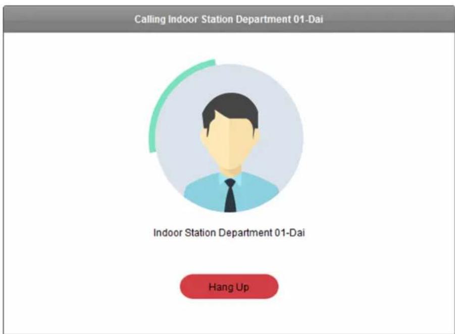
text_image
Calling Indoor Station Department 01-Dai Indoor Station Department 01-Dai Hang UpFigure 21-1 Start Calling Resident
After the call is answered, you will enter the In Call window.
- Optional: After the call is answered, you can do one or more of the following operations:
Adjust the volume of the loudspeaker.
Hang up.
Adjust the volume of the microphone.
21.1.2 Call Client from Indoor Station/Door Station
The residents can call the security center via the indoor station or door station. The security personnel can perform the video intercom of the residents via the client.
Steps
- Enter the Access Control → Video Intercom page.
- Select the client software on the device interface of the indoor station or door station to start calling the client software.
An incoming call dialog will pop up in the client software.
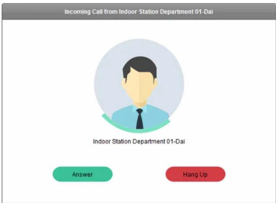
text_image
Incoming Call from Indoor Station Department 01-Dai Indoor Station Department 01-Dai Answer Hang UpFigure 21-2 Incoming Call Window
- Click Answer to answer the call.
After the call is answered, you will enter the In Call window.
- Optional: In the In Call window, you can do one or more of the following operations.
Adjust the volume of the loudspeaker.
Hang up.
Adjust the volume of the microphone.
Remotely open door for door station.
21.1.3 View Live Video of Door Station and Outer Door Station
You can get the live view of the door station and outer door station in the Main View module and control the door station or outer door station remotely.
Before You Start
Add a door station or an outer door station. For details, refer to Add Device.
Perform the following steps to view live videos of the doorstation or outer door station in the Main View module.
Steps
-
Enter the Main View page.
-
Start live view.
-
Double click a door station or an outer door station in the device list.
- Drag a door station an outer door station to a display window.

Note
For detailed operations of live view, refer to Live View.
- Optional: Right-click the live view window to open the right-click menu and click Unlock to open the door remotely.

Note
If the two door stations (such as at front door and back door) are connected, you can select to unlock one of the two doors remotely.
21.2 View Real-Time Call Logs
You can view all the real-time call logs, including dialed call logs, received call logs and missed call logs. You can also directly dial via the log list and clear the logs.
Perform this task if you need to view the real-time video intercom call logs.
Steps
- Enter the Access Control → Video Intercom → Call Log page.
All the call logs will display on this page and you can check the log information, e.g., call status, start time, resident's organization and name, device name and ring or speaking duration.
-
Optional: Click 📞 in the Operation column to re-dial the resident.
-
Optional: Click ✗ in the Operation column to delete the call log.
-
Click Clear button at the upper right corner to clear all the logs.

Note
If you delete or clear the call log in real-time call log page, you can still find the deleted logs in Search → Call Log page. For details, refer to Search Call Logs.
21.3 Release Notice to Resident
You can create different types of notices and send them to the residents. Four notice types are available: advertising, property, alarm, and notice information.
Perform this task when you need to release a notice to the residents on the client software.
Steps
- Enter the Access Control → Video Intercom → Release Notice page.
- Click New Notice on the left panel to create a new notice.
- Click + in the Send To field to select the residents in the Select Resident window.
- Input the notice subject.

Note
Up to 63 characters are allowed in the Subject field.
-
In the Type filed, select the notice type.
-
Optional: Click Add Picture to add a local picture to the notice.

Note
- Up to 6 pictures in the JPGE format can be added to one notice.
-
The maximum size of one picture is 512 KB.
-
Input the notice content.

Note
Up to 1023 characters are allowed in the Content field.
- Click Send to send the notice to the selected resident(s).
The sent notice information will display on the left panel. You can click a notice to view the details on the right panel.
21.4 Search Video Intercom Information
You can search the call logs between the client software and video intercom devices, device unlocking logs, and the sent notice information.
21.4.1 Search Call Logs
You can search the call logs of the video intercom devices in the specified time period.
Perform this task if you need to search the call logs of the video intercom devices.
Steps
- Enter the Access Control → Search → Call Log page.
- Set the search conditions, including call status, device type, start time and end time.
- Click Search.
All the matched call logs will display. - Optional: Click Export to export the call logs to your PC.
21.4.2 Search Unlocking Logs
You can search the unlocking logs of the video intercom devices (DoorStation or Door Station (V Series)) in the specified time period.
Perform this task if you need to search the video intercom device's unlocking logs.
Steps
-
Enter the Access Control → Search → Unlocking Log page.
-
Set the search conditions, including unlocking type, device type, start time and end time.
Unlocking Type
Select who or how to unlock the door, including Unlock by Password, Unlock by Duress, Unlock by Card, Unlock by Resident, or Unlock by Center.
- Click Search.
All the matched unlocking logs will display.
- Optional: Click ▶ in the Capture column in the result list to view the captured pictures.

The function should be supported by device.
- Optional: Click Export to export the unlocking logs to your PC.
21.4.3 Search Notice
You can search the notice sent to the residents in the specified time period.
Perform this task if you need to search the notice sent to the residents.
Steps
-
Enter the Access Control → Search → Notice page.
-
Set the search conditions, including notice type, subject, recipient, start time and end time.
Notice Type
Select the notice type as Advertising Information, Property Information, Alarm Information or Notice Information. Or select All to search notices with all types.
- Click Search.
All the matched notices will display.
-
Optional: Click 📋 in the Operation column to view and edit the notice details, check the sending failed/sent succeeded/unread users, and resend the notice to the sending failed/unread users.
-
Optional: Click Export to export the notices to your PC.
Chapter 22 Log Management
In the Log Management module, you can search the log files (client logs and remote logs) and filter the results, back up log files, and export alarm pictures.
22.1 Search Logs
Two types of log files are provided: client logs and remote logs. The client logs refer to the log files of the client and are stored on the local PC; the remote logs refer to the log files of the connected devices and are stored on the local device.
22.1.1 Search Client Logs
You can search the log files of the client, or the logs of the remote devices.
Perform the following steps to search the log files of the client.
Steps
- Open the Log Search page.
- Select Client Logs as the to-be-searched log type.
- Click 📋 to specify the start time and end time.

Note
You can search the logs within one month.
4. Click Search.
The log files between the start time and end time will be displayed on the list. You can check the operation time, type and other information of the logs.
- Optional: Narrow the time range or filter the log type for search if there are too many log files.

Note
See Filter Logs for detailed information about filtering logs.
22.1.2 Search Connected Device Logs
You can search the remote logs, namely, the log files of the connected device.
Perform the following steps to search the logfiles of the connected device.
Steps
- Open the Log Search page.
-
Select Remote Logs as the to-be-searched log type.
-
Click 📄 to specify the start time and end time.

You can search the logs within one month.
- Click Search.
The log files between the start time and end time will be displayed on the list. You can check the operation time, type and other information of the logs.

Narrow the time range or filter the log type for search if there are too many log files.
22.2 Filter Logs
After being searched out successfully, the log files can be filtered by the keyword or condition, and thus you can find the logs as you want.
Before You Start
Search logs. See Search Client Logs and Search Connected Device Logs for details.
Perform the following steps to filter logs.
Steps
- Click Log Search on the control panel to enter the Log Search page.
- Click Log Filter or ▼ on the Log Search page to expand the Log Filter panel.
-
Select filtering mode.
-
Select Filter by Keyword, and then input keyword for filtering in the text field.
-
Or select Filter by Condition, and then specify log type in the drop-down list.
-
Optional: Click More... to filter the log files more accurately.
-
Click Filter to start filtering.
22.3 Back Up Logs
The log files, including the client logs and server logs, can be exported for backup.
Perform this task if you need to back up logs.
Steps
- Click Log Search on the control panel to open the Log Search page.
- Set the condition and search the log file.
- Click Backup Log to open the Backup Log window.
- Click □ and select a local saving path and set a name for the file.
- Click Backup to export the selected log file for backup.
- Optional: After backup the log file, you can perform the following operation.
Check Backup Log Files Information
Click File → Open Log File on the menu bar to check the information of the backup log files on local PC.
22.4 Export Pictures
The alarm pictures, which are stored in the storage server, can be exported to the local PC.
Before You Start
Add storage device to the client for storing the video files and pictures of the added encoding devices, see Store Picture and Video on Storage Device
Perform the following steps to export pictures.
Steps
-
Click Log Search on the control panel to open the Log Search page.
-
Search client logs.
See Search Client Logs for details.
- Select Alarm Log as the log type when filtering the results.

See Filter Logs for details.
-
Select the alarm pictures.
-
Click Export Picture to open the Export Picture window.
-
Click □ and select a local saving path, and then set a name for the file.
-
Click Export to export the selected pictures.
Chapter 23 Account Management
Multiple user accounts can be added to the client software, and you are allowed to assign different permissions to different users if needed.
Perform this task to add an user account.
Steps
i Note
The user account you registered to log in the software is set as the super user.
- Enter the Account Management page.
- Click Add User to open the Add User window.
- Select the user type from the drop-down list.
Administrator
The administrator account has all permissions by default, and can modify the passwords and permissions of all operators and its own.
Operator
The operator account has no permission by default and you can assign the permissions manually. An operator can only change the password of its own account.
- Input the user name, password, and confirm password as desired.
Caution
The password strength of the device can be automatically checked. We highly recommend you change the password of your own choosing (using a minimum of 8 characters, including at least three kinds of following categories: upper case letters, lower case letters, numbers, and special characters) in order to increase the security of your product. And we recommend you reset your password regularly, especially in the high security system, resetting the password monthly or weekly can better protect your product.
Proper configuration of all passwords and other security settings is the responsibility of the installer and/or end-user.
- Check the checkboxes to assign the permissions to the created user.
- Optional: Select a user in the Copy from drop-down list to copy the permissions of the selected user.
- Optional: Click Default Permission to restore the default permissions of this user.
- Click Save.
i Note
Up to 50 user accounts can be added for the client software.
After created user account successfully, the user account is added to the user list on the Account Management page.
- Optional: Perform the following operations after the user account is created.
Edit User Select a user from the list and click Edit User to edit the user information.

Only the password of the super user can be edited.
Delete User Select the user from the list and click Delete User.

You cannot delete the super user.
Copy to For super and administrator user, you can click Copy to copy the permissions to other user(s).
Chapter 24 System Configuration
The general parameters, live view and playback parameters, image parameters, file saving paths, icon of live view and playback toolbar settings, keyboard and joystick shortcuts, alarm sounds, email settings, video intercom parameters, access control settings, and security certificate can be configured.
24.1 Set General Parameters
You can configure the frequently-used parameters, including log expired time, network performance, and etc.
Perform the following task when you need to set the abovementioned parameters.
Steps
- Open the System Configuration page.
- Click General tab to enter the General Settings page.
- Configure the general parameters.
Log Expiry Date
The time for keeping the log files. Once exceeded, the files will be deleted.
Network Performance
Set the network conditions to Normal, Better or Best.
Maximum Mode
Select Maximize or Full Screen as the maximum mode. Maximize mode can maximize the display and show the taskbar. Full Screen mode can display the client in full-screen mode.
Enable Auto-login
Log into the client software automatically.
Pop up Security Prompt When Using Default Password
If the default password of the added device has not been changed, the prompt will pop up for notification.
Enable Alarm Triggered Pop-up Image
Enable the image pop-up when alarms occur. You can also click 📄 or 📋 to enable/disable the image pop-up in Alarm Event interface.
Pop Up Alarm Image for Minimized Client When Alarm Triggered Pop-up Image Enabled
Enable the alarm image popping up when the client is minimized if the Alarm Triggered Pop-up Image function is enabled.

For enabling the Alarm Triggered Pop-up Image, refer to Alarm Configuration.
Automatic Time Synchronization
Automatically synchronize the time of the added devices with the time of the PC running the client at a specified time point.
Enable Keyboard and Joystick
Enable the keyboard or joystick. After enabled, you can set the shortcuts for the keyboard and joystick.

For details, refer to Set Keyboard and Joystick Shortcuts.
Registration Management Server Port
EHome port for registration management server. The port number should be between 2000 to 65535. The default port number is 7660.

Restart the client to take effect.
Alarm Management Server Port
EHome port for alarm management server. The port number should be between 2000 to 65535. The default port number is 7300.

Restart the client to take effect.
Web Server Port
The port for device remote configuration via web server. The port number should be between 1 to 65535. The default port number is 80.

Restart the client to take effect.
4. Click Save.
24.2 Set Live View and Playback Parameters
You can set the parameters for live view and playback, including picture format, pre-play duration, etc.
Perform the following task when you need to set the parameters for live view and playback.
Steps
- Open the System Configuration page.
- Click Live View and Playback tab.
- Configure the live view and playback parameters.
Merge Downloaded Video Files
Set the maximum size of merged video file for downloading the video file by date.
Search Video Files Stored in
Search the video files stored in the local device, in the storage server, or both in the storage server and local device for playback.
Pre-play for
Set the pre-play time for event playback. By default, it is 30s.
Enable Screen Toolbar Display
Show the toolbar on each display window in live view or playback.
Prioritize Playback of Video Files on Storage Server
Play back the video files recorded on the storage server preferentially. Otherwise, play back the video files recorded on the local device.
Resume Latest Live View Status After Restart
Resume the latest live view status after you log into the client again.
Disconnect Background Videos in Single Live View
In multiple-window division mode, double-click a live video to display it in 1-window division mode, and the other live videos will be stopped for saving the resource.
Enable Wheel for Zoom
Use the mouse wheel for zoom in or out of the video in PTZ mode, or for zoom in or restoring of the video in digital zoom mode. In this way, you can directly zoom in or out (or restore) the live video by scrolling the mouse.
Skip Unconcerned Video during VCA Playback
Skip the unconcerned video during VCA playback and the unconcerned video will not be played during VCA playback.
4. Click Save.
24.3 Set Image Parameters
The image parameters of the client can be configured, such as view scale, play performance, etc.
Perform the following task when you need to set image parameters.
Steps
- Open the System Configuration page.
- Click Image tab to enter the Image Settings interface.
3. Configure the image parameters.
View Scale
The view scale of the video in live view or playback. It can be set as Full Screen, 4:3, 16:9, or Original Resolution.

You can also set the view scale in Live View module. For details, refer to Live View.
Play Performance
The play performance of the live video. It can be set as Shortest Delay, Balanced, or Fluency.
Auto-change Stream Type
Change the video stream (main stream or sub-stream) automatically in live view according to the size of the display window.

When the window division is larger than 9, it will switch to sub-stream automatically.
Hardware Decoding Preferred
Set to enable decoding by hardware for live view and playback. Hardware Decoding can provide better decoding performance and lower CPU usage when playing the HD videos during live view or playback.
Enable Highlight
Mark the detected objects with green rectangles in live view and playback.
Display Transaction Information
Display the transaction information on the live view image.
VCA Rule
Display the VCA rule in the live view.
Enable Frame Extracting for High-speed Playback
When play back the video in high-speed (8x speed and above), you can disable this function to make the image of playback more fluent to view the details.
Display Temperature on Captured Picture
For the thermal device, set to display the temperature information on the captured pictures.

After enabled this function, the Picture Format in System Configuration → Live View and Playback will change to JPEG and is not editable.
4. Click Save.
24.4 Set File Saving Path
The video files from manual recording, the captured pictures and the system configuration files are stored on the local PC. The saving paths of these files can be set.
Perform the following task when you need to set the file saving path.
Steps
- Open the System Configuration page.
- Click File tab to enter the File Saving Path Settings page.
- Click and select a local path for the files.
- Click Save.
24.5 Set Icons Shown on Toolbar
The icons and the order on the toolbar in the live view and playback window can be customized. You can set to display what icons and set the icon order.
Perform the following task when you need to set icons shown on Toolbar.
Steps
- Open the System Configuration page.
- Click Toolbar tab to enter the Toolbar Settings page.
- Select the icon to display on the toolbar.
- Optional: Drag the icon to set the icon order when displaying on the toolbar.
Table 24-1 Icons on Live View Toolbar
| Stop Live View Stop the live view in the display window. | |
| Capture Capture the picture in the live view process. The capture picture is stored in the PC. | |
| Record Start manual recording. The video file is stored in the PC. | |
| PTZ Control Start PTZ mode for speed dome. Click and drag in the view to perform the PTZ control. | |
| Two-way Audio Start the two-way audio with the device in live view. | |
| Digital Zoom Enable the digital zoom function. Click again to disable the function. | |
| Instant Playback Switch to the instant playback mode. | |
| Remote Configuration Open the remote configuration page of the camera in live view. |
Table 24-2 Icons on Playback Toolbar
| [CTST] | Capture Capture the picture in the live view process. The capture picture is stored in the PC. |
| [40H61] | Record Start manual recording. The video file is stored in the PC. |
| [3827] | Digital Zoom Enable the digital zoom function. Click again to disable the function. |
| [X282] | Download Download the video files of the camera and the video files are stored in the PC. You can select to download by file or by date. |
5. Click Save.
24.6 Set Keyboard and Joystick Shortcuts
The keyboard can be connected to the client and be used to control the PTZ cameras. You can set the shortcuts for keyboard and joystick to get quick and convenient access to the commonly used actions.
Perform this task when you need to set keyboard and joystick shortcuts.
Steps

Note
This configuration page will display after enabling keyboard and joystick in General Settings. For details, refer to Set General Parameters.
- Enter the System Configuration module.
- Click Keyboard and Joystick to show the Keyboard and Joystick Shortcut Settings area.
- Select the COM port from the drop-down list for keyboard if the keyboard is connected to the PC installed with the client.

Note
You can enter the Device Manger of the PC to check the COM port, which the keyboard is connected to.
- Set shortcuts for keyboard and joystick.
1) Select a certain function name on Function column.
2) Double-click the item field under the PC Keyboard, USB Joystick or USB Keyboard column.
3) Select the compound keys operation or number from the drop-down list to set it as the shortcuts for the function of the keyboard or USB joystick.
- Click Save.
Example
For the Focus (+) function, if you set Home, 1, and F1 as the shortcuts of the PC Keyboard, USB Joystick and USB Keyboard, you can press the Home key on PC keyboard, control the joystick to the 1 direction, or press F1 key on USB keyboard to zoom in.
24.7 Set Alarm Sound
When the alarm, such as motion detection alarm, video exception alarm, etc., is triggered, the client can be set to give an audible warning and the sound of the audible warning can be configured.
Perform the following task when you need to set the alarm sound.
Steps
- Open the System Configuration page.
- Click Alarm Sound tab to enter the Alarm Sound Settings page.
- Optional: Click ... and select the audio files from the local path for different alarms.

Note
There are six pre-defined alarm sound type in the list.
- Optional: Add customized alarm sound.
1) Click Add to add customized alarm sound.
2) Double click the Type field to customize the alarm sound name as desired.
3) Click ... and select the audio files from the local path for different alarms.
-
Optional: Click 📋 for a testing of the audio file.
-
Optional: Select the added custom alarm sound and click Delete to delete it.
-
Click Save.

Note
The format of the audio file can only be WAV.
24.8 Set Email Parameters
An email notification can be sent when a system alarm occurs. To send the email to some specified receivers, the settings of the email need to be configured before proceeding.
Perform the following task when you need to set email parameters.
Steps
- Open the System Configuration page.
- Click Email tab to enter the Email Settings interface.
- Input the required information.
Server Authentication (Optional)
If your email server requires authentication, check this checkbox to use authentication to log into the server and enter the login user name and password of your email account.
Encryption Type
You can check the radio to select Non-Encrypted, SSL, or STARTTLS.
Port
Input the communication port of email service. The port is 25 by default.
User Name
Input the user name of the sender email address if Server Authentication is checked.
Password
Input the password of the sender Email address if Server Authentication is checked.
Receiver 1 to 3
Input the email address of the receiver. Up to 3 receivers can be set.
- Optional: Check Enable SSL to increase the security of email sending.
- Optional: Click Send Test Email to send an email to the receiver for test.
- Click Save.
24.9 Set Video Intercom Parameters
You can configure the video intercom parameters according to actual needs.
Perform the following task when you need to set video intercom parameters.
Steps
- Open the System Configuration page.
- Click the Video Intercom tab to enter the Video Intercom Settings page.
- Input the required information.
Ringtone
Click ... and select the audio file from the local path for the ringtone of indoor station.
Optionally, you can click for a testing of the audio file.
Max. Ring Duration
Specify the seconds that the ring will last for at most. The maximum ring duration can be set from 15s to 60s.
Max. Speaking Duration with Indoor Station
Specify the seconds that the call with indoor station will last for at most. The maximum speaking duration between indoor station and the client can be set from 120s to 600s.
Max. Speaking Duration with Door Station
Specify the seconds that the call with door station will last for at most. The maximum speaking duration between door station and the client can be set from 90s to 120s.
4. Click Save.
24.10 Set Access Control Parameters
You can set the time so that the system will get the access control events which are not uploaded to the client from the access control device and save them to the client's database. For example, if the device is armed by another client B, the triggered events cannot be uploaded to the current client A during the arming period. When the client A arms the device again, you can synchronize these events from device to client A via this function.
Perform the following steps to set the access control parameters.
Steps
- Open the System Configuration page.
- Click Access Control tab to enter the Access Control Settings interface.
- Check Auto-synchronize Access Control Event to enable this function and set the time for synchronization.
- Click Save.
24.11 Manage Security Certificate
For the data security purpose, the security certificate of clients and added servers (stream media server) should be same.
Before adding the stream media server to the client, you should export the service certificate stored in the client, and import it to the stream media server. If multiple clients use the same server, you should make the security certificates of the clients and the server same with each other.
24.11.1 Export Certificate from Client
You can export the security certificate from the current client and import the exported certificate file to the server or other clients.
Perform the following steps to export the security certificate from the client.
Steps
- Open the System Configuration page.
- Click Security Certificate tab to enter the security certificate interface.
- Save the certificate file in the local PC.
The certificate file is in XML format.
- Click Save.
i Note
- After exporting the certificate, you can copy the certificate to the PC installed with the service and import it to the stream media server, or to other clients.
- For importing to the stream media server, refer to Import Certificate to Stream Media Server.
24.11.2 Import Certificate to Client
If there are multiple clients accessing the same server, you should import the same certificate to the clients and server.
Before You Start
You should export the security certificate from one of the client.
i Note
For details, refer to Export Certificate from Client.
Perform the following steps to import the security certificate to the client.
Steps
- Copy the certificate file exported from other client to the local PC.
- Open the System Configuration page.
- Click Security Certificate tab to enter the security certificate interface.
- Click Import.
- Select the certificate file from your local PC.
- Click Save.
i Note
Please restart the system to take effect.
Appendix A. Custom Wiegand Rule Descriptions
Take Wiegand 44 as an example, the setting values in the Custom Wiegand tab are as follows:
| Custom Wiegand Name | Wiegand 44 | ||||
| Total Length 44 | |||||
| Transformation Rule (Decimal Digit) | byFormatRule[4]=[1][4][0][0] | ||||
| Parity Mode XOR Parity | |||||
| Odd Parity Start Bit Length | |||||
| Even Parity Start Bit Length | |||||
| XOR Parity Start Bit 0 Length per Group 4 Total Length 40 | |||||
| Card ID Start Bit 0 Length 32 Decimal Digit 10 | |||||
| Site Code Start Bit | Length Decimal Digit | ||||
| OEM Start Bit | Length Decimal Digit | ||||
| Manufacturer Code Start Bit | 32 Length | 8 Decimal Digit 3 | |||
Wiegand Data
Wiegand Data = Valid Data + Parity Data
Total Length
Wiegand data length.
Transportation Rule
4 bytes. Display the combination types of valid data. The example displays the combination of Card ID and Manufacturer Code. The valid data can be single rule, or combination of multiple rules.
Parity Mode
Valid parity for Wiegand data. You can select either odd parity or even parity.
Odd Parity Start Bit, and Length
If you select Odd Parity, these items are available. If the odd parity start bit is 1, and the length is 12, then the system will start odd parity calculation from bit 1. It will calculate 12 bits. The result will be in bit 0. (Bit 0 is the first bit.)
Even Parity Start Bit, and Length
If you select Even Parity, these items are available. If the even parity start bit is 12, and the length is 12, then the system will start even parity calculation from bit 12. It will calculate 12 bits. The result will be in the last bit.
XOR Parity Start Bit, Length per Group, and Total Length
If you select XOR Parity, these items are available. Depending on the table displayed above, the start bit is 0, the length per group is 4, and the total length is 40. It means that the system will calculate from bit 0, calculate every 4 bit, and calculate 40 bits in total (10 groups in total). The result will be in the last 4 bits. (The result length is the same as the length per group.)
Card ID Start Bit, Length, and Decimal Digit
If you use the transformation rule, these items are available. Depending on the table displayed above, the card ID start bit is 0, the length is 32, and the decimal digit is 10. It represents that from bit 0, there are 32 bits represent the card ID. (The length here is calculated by bit.) And the decimal digit length is 10 bits.
Site Code Start Bit, Length, and Decimal Digit
If you use the transformation rule, these items are available. For detailed information, see the explanation of the card ID.
OEM Start Bit, Length, and Decimal Digit
If you use the transformation rule, these items are available. For detailed information, see the explanation of the card ID.
Manufacturer Code Start Bit, Length, and Decimal Digit
If you use the transformation rule, these items are available. Depending on the table displayed above, the manufacturer code start bit is 32, length is 8, and decimal digit is 3. It represents that from bit 32, there are 8 bits are manufacturer code. (The length here is calculated by bit.) And the decimal length is 3.
Appendix B. Troubleshooting
Here are some common symptoms when operating the client software. We provide the possible causes and corresponding solutions to solve the problems.
B.1 Failed to get the live view of a certain device.
Problem
Failed to get the live view of a certain device.
Possible Reasons
- Unstable network or the network performance is not good enough.
- The device is offline.
- Too many accesses to the remote device cause the load of the device too high.
- The current user has no permission for live view.
- The version of the client software is below the needed version.
Solutions
- Check network status and disable other not in use process on your PC.
- Check the device network status.
- Restart the device or disable other remote access to the device.
- Log in with the admin user and try again.
- Download the client software of the latest version.
B.2 Local recording and remote recording are confused.
Problem
Local recording and remote recording are confused.
Solutions
- The local recording in this manual refers to the recording which stores the video files on the HDDs, SD/SDHC cards of the local device.
- The remote recording refers to the recording action commanded by the client on the remote device side.
B.3 Failed to download the video files or the downloading speed is too slow.
Problem
Failed to download the video files or the downloading speed is too slow.
Possible Reasons
- Unstable network or the network performance is not good enough.
- The NIC type is not compatible.
- Too many accesses to the remote device.
- The current user has no permission for playback.
- The version of the client software is below the required version.
Solutions
- Check network status and disable other not in use process on your PC.
- Directly connect the PC running the client to device to check the compatibility of the NIC card.
- Restart the device or disable other remote access to the device.
- Log in with the admin user and try again.
- Download the client software of the latest version.
Appendix C. FAQ (Frequently Asked Questions)
Here are some frequently asked questions when operating the client software. We provide the corresponding answers to help the users to solve the problems.
C.1 During live view, why an error message with error code 91 prompts?
Question
During live view, why an error message with error code 91 prompts?
Answer
For live view of multiple windows, the channel may not support sub stream. You should disable the function of Auto-change Stream Type in System Configuration → Image, and select the appropriate steam type for live view.
C.2 During live view, why the image is blurred or not fluent?
Question
During live view, why the image is blurred or not fluent?
Answer
Check the driver of video card. We highly recommend you update the driver of video card to the latest version.
C.3 Why the memory leaked and the client crashed after running for a while?
Question
Why the memory leak and the client crashed after running for a while?
Answer
In the installation directory of the client software, open the Setup.xml file with Notepad and modify the value of EnableNetandJoystickCheck to false. Restart the client, and if the problem is still not solved, contact our technique support.
C.4 During live view, when getting stream via the Stream Media Server, why an error message with error code 17 prompts?
Question
During live view, when getting stream via the Stream Media Server, why an error message with error code 17 prompts?
Answer
Check the port mapping of Stream Media Server, especially RTSP port.
Appendix D. Error Code
| Code | Error Name Description | |
| Guarding Vision | ||
| 317 | No videos. It will be prompted when | the user has no permission to play back. |
| HCNetSDK.dll | ||
| 1 | Invalid user name or password. | |
| 2 | No permission. The user in the device | has no enough permission. |
| 4 | Invalid channel number. It will be prompted in the live view of remote screen control. | |
| 5 | No more devices can be connected. | |
| 7 | Failed to connect the device. | |
| 23 | Not supported. | |
| 29 | Operation failed. | |
| 43 | No buffer. It will be prompted when adding a device and the device port is occupied by a web server. | |
| 55 | Invalid IP address. | |
| 56 | Invalid MAC address. | |
| 91 | The channel does not support the operation. | It will be prompted when failed to get the sub stream. |
| 96 | The device is not registered on the DDNS. | |
| 153 | The user is locked. | |
| 250 | The device is not activated. | |
| 404 | Channel No. error or the device does not support the sub stream. | It will be prompted when failed to get the sub stream or the sub stream does not exist. |
| 424 | Failed to receive the data for RTSP SETUP. | It will be prompted when adding the live view for the software DVS via external network. |
| 800 | No more bandwidth can be used. | |
| Playctrl.dll | ||
| 2 | The stream is not a Video & Audio stream. | |
| 6 | The playback window turns black when adopting H.265 in the 64-bit operating system. | |
| SMS | ||
| 3 | The connection problem between the software and the stream media server. | |
| 17 | The streaming problem between the stream media server and the device. | |