SP-403M Super - Car radio Xomax - Free user manual and instructions
Find the device manual for free SP-403M Super Xomax in PDF.


| Product Type | FM/USB/SD MP3 Player |
| Brand | Xomax |
| Model | SP-403M Super |
| Form Factor | 1 DIN |
| Power Supply | 12V DC (negative ground) |
| Max Power Output | 4 x 50W (peak) |
| Speaker Impedance | 4 - 8 Ohm |
| Radio Frequency Range | FM 87.5 - 108 MHz |
| Supported Media | USB, SD/SDHC (up to 32GB) |
| Audio Formats | MP3, WMA, WAV |
| Remote Control | Included (battery CR2025) |
| Display | LED backlit LCD |
| Inputs | USB, SD, AUX (3.5mm) |
| Outputs | 4 RCA pre-outs (Front/Rear) |
| ISO Connector | Standard ISO socket (A/B ports) |
| Antenna Connector | ISO (active antenna support via phantom power) |
| Dimensions (W x H x D) | 178 x 50 x 160 mm |
| Weight | 0.5 kg |
| Color | Black |
| Installation Depth | ≤ 160 mm |
Frequently Asked Questions - SP-403M Super Xomax
User questions about SP-403M Super Xomax
0 question about this device. Answer the ones you know or ask your own.
Ask a new question about this device
Download the instructions for your Car radio in PDF format for free! Find your manual SP-403M Super - Xomax and take your electronic device back in hand. On this page are published all the documents necessary for the use of your device. SP-403M Super by Xomax.
USER MANUAL SP-403M Super Xomax
natural_image
Illustration of a crossed wrench and screwdriver with a red button, symbolizing repair or tools (no text or symbols present)Installation Manual
ENGLISH
Montageanleitung
DEUTSCH
SUPER
natural_image
3D mechanical assembly diagram showing a bracket with a blue circle highlighting a component, no text or symbols presentnatural_image
Illustration of a mechanical device with control panel and tray, no visible text or symbolsnatural_image
Illustration of a cabinet interior with a red circular badge labeled '6' (no text or symbols on the main diagram)natural_image
Close-up of a black plastic electrical connector with multiple colored wires and connectors (no text or symbols visible)natural_image
Symbol of a trash bin crossed with a diagonal line and a horizontal bar below (no text or labels)Installation instructions
SP-403M
Thank you for purchasing one of our SUPER products! We appreciate your confidence. Enjoy your brand new multimedia unit!

i
Please read the following manual carefully before you install and use the unit. Please save this manual in case you will need to clarify further possible questions regarding installation and usage of our product.
We recommend you to let the technician install the unit in your vehicle.
You can find the detailed manual for your SUPER product on our homepage: www.xomax.de/download
Safety instructions and precautions 24
Installation 26
Installation instructions 28
1 Installation steps ......28
2 Fixture of the fixation sheet......28
3 Fixture of the installation frame ....29
4 Connecting the unit......29
5 Fixture of the unit....30
Deinstallation instructions 31
1 Preparation of the instruments.....31
2 Loosening of the fixation nut .....31
3 Usage of the extraction keys ......32
4 Loosening of the unit......32
5 Removing of the unit....33
6 Removing installation accessories..33
Connection schedule - Cinch multicore 34
Connection schedule - ISO plug 35
ISO socket pin assignment 36
Port A (power supply) 36
Port B (loud speakers)......36
ISO cable connections 37
Common solutions 38
Disposal of an old unit 40
Disposal of the battery 40
Safety instructions and precautions
Handling by stop only
To avoid any accidents please don't handle the unit while you driving. Please stop and park the vehicle at safety place and handle the unit casually.
Installation
Please read the following manual carefully before you install the unit. We recommend you to let the technician install the unit in your vehicle.
! Regular loudness
Please set the loudness of the unit to the appropriate level so you were still able to hear exterior noises especially traffic warning signals. Furthermore the higher loudness level can damage your hearing organs.
! Repair of the unit
Do not open the unit. Do not try to repair the unit by yourself due to any emerging technical problems. While opening the unit by yourself exists the danger to be electrocuted.
Do not use the unit any further since you detect any kind of technical problems.
Leave all the repair operations to professional technicians.
Due to flawed warranty seal the warranty becomes invalid.
Power supply
Use the unit connected only to 12 Volt on-board power supply. The minus (-) should be connected with the ground (GND) (negative).
Due to wrong grounding exists the danger of fire. In case of doubt please consult with professional technicians.
Replacement of fuses
While replacing the fuse please make sure that the new fuse has the same properties as the old one, especially the amperage.
Overheating
Do not occlude the vent holes to avoid the heat generation and accumulation in the unit. Otherwise exists the danger of fire.
! Regular temperature
Please make sure that the temperature inside the vehicle amounts to not more than +60 C.
If it's too hot inside the vehicle, do not turn the unit on until the inside temperature of the cabin descends.

Cleaning of the unit
Please keep the unit clean and remove the dust from it regularly. Please use for that a soft and dry cleaning rag.
Major soilings can be removed carefully with the wet cleaning rag. Do not use any chemical or alcohol-containing detergents to avoid the damage of the unit's varnish.

Handling the touchscreen
Do not press the to the touch keys or other symbols too hard – it may lead to image distortions, unit malfunctions and touchscreen damages.
Do not use any sharp articles to use the touchscreen. Please handle the touchscreen with your finger or with the appropriate stylus.

Moisture
To avoid the danger of fire or the electric shock do not put the unit in to the moist environment (e.g. adverse weather conditions, inappropriate wet cleaning etc.)
Installation
!We recommend you to let a professional technician install the unit in your vehicle.

WARNING!
Please read these advices carefully before installation procedure.
The damages caused by an inappropriate installation are not covered by warranty.
To avoid the risk of losing the warranty please let a specialist accomplish the installation of the unit.
»To avoid a short circuit please disconnect the vehicle battery before the installation. To do it properly please read the manual of the vehicle.
»Please be aware that this unit has an 1 DIN standart size. Make sure that your vehicle is equipped with a car radio slot of required size.
»As may be the case you will need a suitable faceplate, adapter or other accessories. These could be provided from your local specialist supplier.
»The connection cables may not be cutted or short-circuited. Otherwise the warranty becomes invalid.
»Before the installation please make sure that the vehicle has the 12 Volt on-board power supply.
»The minus (-) should be connected with the ground (GND) (negative).
»Please tag the polarity of the available speakers before you disconnect the vehicle battery.
»A proper grounding of the unit's housing requires a clean ground connection. Thus the grounding area should be rust-, stain- and dust-free.
»Please ground the cable separately from other heavy current devices such as an amplifier etc.
»Please ensure that the coloured cables are connected according to the wiring diagram. The wrong wiring may lead to malfunctions or even damages of the electric elements of the vehicle.
»Please note that the connection cables of this unit and of the other devices may have the same purpose but the different colour. For this reason while connecting this unit with the other devices please ensure that both of the cables in each case have the same purpose. To connect everything correctly please refer to the manuals of the both devices.
»Please ensure that the negative
speaker cable is in each case connected with the negative speaker terminal of the ISO port. Do not ever connect the negative speaker cables with the vehicle body.
»This unit is designed and construed for connection with 4 speakers. Do not combine this unit with devices that are designed and construed for connection with 2 speakers.
»The speakers should feature the impedance of 4-8 Ohm and a sufficient wattage.
»Please ensure that the speakers you are connecting with the unit are intact. Damaged speakers can impair the unit.
»To avoid a short circuit please isolate all cable junctions and endings of the unused cables with the electrical tape.
»All the cables should be layed and fixated tidy and properly. The cables should not contact any movable or hot objects.
»If your vehicle doesn't have an "ACC" ignition position, please connect the red cable with the ignition switch. Otherwise the unit will not turn off automatically, causing the discharging of the vehicle battery.
»To avoid a rogue and hazardous short circuit do not lay the yellow cable
through the engine bay in order to connect it with the vehicle battery.
»Do not ever connect speaker cables among one another. In case you do not want to connect all the 4 speakers with the unit please isolate the endings of unused cables with the electrical tape to prevent a short circuit.
»Do not ever connect the negative speaker cables with the vehicle body.
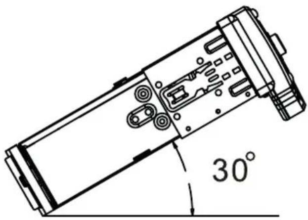
»To ensure a flawless performance of the unit the intergration angle should amount to +/- 30.
Installation instructions

1 Installation steps
- fixture accessories (optional): 1 x fixation metal sheet, 1 x bolt, 1 x nut, 1 x washer
-
installation frame
-
dual-ended bolt
- unit
* Installation frame is already firmly fixed to the unit's housing by delivery.
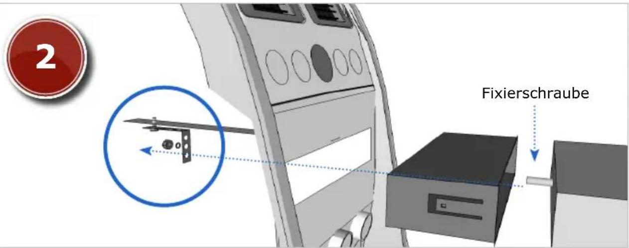
2 Fixture of the fixation sheet
This step can not be accomplished in every vehicle, thus it may be possibly skipped. The fixation metal sheet should be fixated in the vehicle first,
then the dual-ended bolt of the unit should be pulled through one of the holes in the fixation metal sheet.
Later (see page 30) the unit will be fixed to the metal sheet with the washer and the nut.
natural_image
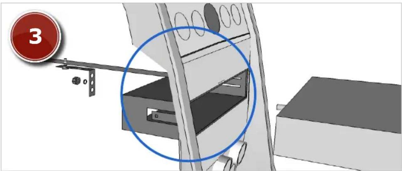
Technical diagram of a mechanical assembly with a blue circle highlighting a component, no visible text or symbols3 Fixture of the installation frame
Please remove first the installation frame (if it's included in delivery) from the unit. Please use for that the extraction keys (see page 31).
Possibly the faceplate should be removed as well. Please insert the installation frame into the car radio slot. Then bend all the cogs outwards to fixate the frame inside the slot.

4 Connecting the unit
Please connect the ISO port first with the ISO plug of the unit, then with the one of the vehicle. Do not forget to connect the radio aerial.
Now slide the unit carefully into the already fixated frame till it clicks into place.
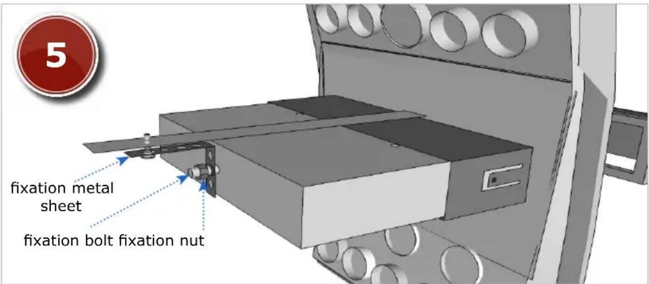
5 Fixture of the unit
This procedure refers to the step 2 and may be possibly skipped as well. As earlier required (see page 28), the dual-ended bolt of the unit should be pulled through one of the holes in
the fixation metal sheet. Now the unit should be fixated to the metal sheet with the washer and the nut.
Deinstallation instructions

1 Preparation of the instruments
To deinstall the unit you will need a spanner (a wrench) to unloose the fixation nut and 2 extraction keys (optional)
to release the unit from the installation frame.

2 Loosening of the fixation nut
First of all please unloose the fixation nut on the rear side of the unit by spanner (wrench).
This step may be possibly skipped, if due to the lack of space the unit initially was not fixated to the fixation metal sheet.

3 Usage of the extraction keys
Please insert the extraction keys into the dedicated recesses between the installation frame and the unit's housing.
In each case the key should be inserted centered, the inserting point should be equally distanced both from the top and from the bottom.
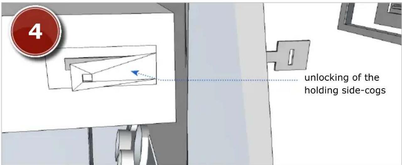
4 Loosening of the unit
When and as long as inserted, the extraction keys press the holding side-cogs outwards so that the unit is
released from the installation frame and can be carefully pulled out.
natural_image
Illustration of a medical or laboratory instrument with a red circular badge labeled '5' (no text or symbols on the device itself)5 Removing of the unit
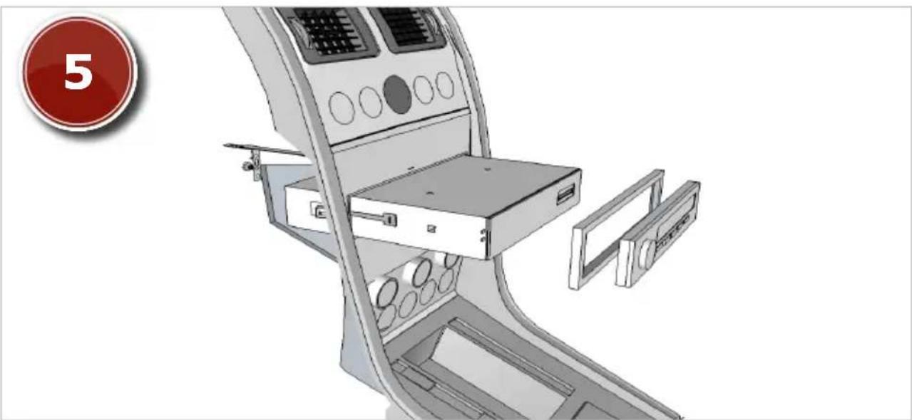
Afterwards please disconnect all the cables incl. the ISO multicore.
Now pull the unit carefully out of the installation frame or out of the car radio slot in case the frame was already firmly fixed to the unit by delivery.

natural_image
Illustration of a cabinet interior with a red circular badge labeled '6' in the corner (no text or symbols on the main structure)6 Removing of the installation accessories
Finally remove all the installation accessories such as fixation metal sheet and installation frame.
Connection schedule - Cinch multicore

flowchart
graph TD
    A["Radio System"] --> B["Audio OUT FR"]
    A --> C["Audio OUT RR"]
    A --> D["Audio OUT RL"]
    A --> E["Audio OUT FL"]
    B --> F["Red Red Head"]
    C --> G["Red Red Head"]
    D --> H["White Red Head"]
    E --> I["White Red Head"]
    F --> J["e.g. amplifier optional"]
    G --> J
    H --> J
    I --> J
    J --> K["loud Speakers"]
    style A fill:#f9f,stroke:#333
    style K fill:#ccf,stroke:#333
Connection schedule - ISO plug

flowchart
graph TD
    A["12V"] -->|radio aerial active| B["photom power"]
    B --> C["permanent current"]
    C --> D["ignition"]
    D --> E["loud speakers"]
    E --> F["rear right"]
    E --> G["front right"]
    E --> H["front left"]
    E --> I["rear left"]
    F --> J["A"]
    G --> K["A4"]
    H --> L["A5"]
    I --> M["A7"]
    J --> N["A8"]
    K --> O["A8"]
    L --> P["A8"]
    N --> Q["A8"]
    O --> R["A8"]
    P --> S["A8"]
    Q --> T["A8"]
    U["ISO cable"] --> V["B"]
    V --> W["ISO plug"]
    style A fill:#f9f,stroke:#333
    style B fill:#ccf,stroke:#333
    style C fill:#cfc,stroke:#333
    style D fill:#fcc,stroke:#333
    style E fill:#ffc,stroke:#333
    style F fill:#cff,stroke:#333
    style G fill:#ffc,stroke:#333
    style H fill:#ffc,stroke:#333
    style I fill:#ffc,stroke:#333
    style J fill:#cfc,stroke:#333
    style K fill:#cfc,stroke:#333
    style L fill:#cfc,stroke:#333
    style M fill:#cfc,stroke:#333
    style N fill:#cfc,stroke:#333
    style O fill:#cfc,stroke:#333
    style P fill:#cfc,stroke:#333
    style Q fill:#cfc,stroke:#333
    style R fill:#cfc,stroke:#333
ISO socket pin assignment

Port A (power supply)
On the A side you can find the port for power supply.
A1 - spare
A2 - spare
A3 - spare
A4 - (+) 12Volt battery / steady plus *
A5 - electric antenna (+)
A6 - spare
A7 - (+) 12Volt ignition plus *
A8 - minus / ground (-)
* - Some vehicle manufacturers use their own pin assignment. Especially the terminals A7 (ignition plus) and A4 (steady plus) are often interchanged. The incorrect connection in this case leads to following problem: the unit can not be turned on if the ignition is off and all the saved settings are lost as soon as the unit will be turned off. If these problems appear the connections A4 and A7 should be interchanged.
Port B (loud speakers)
On the B port you can find the speakers terminals.
B1 - rear speaker right (+)
B2 - rear speaker right (-)
B3 - front speaker right (+)
B4 - front speaker right (-)
B5 - front speaker left (+)
B6 - front speaker left (-)
B7 - rear speaker left (+)
B8 - rear speaker left (-)
The terminals are coloured by pairs, in each case one (+) and one (-).
Though the design of ISO port is standardized, it's pin assignment is not and may vary. Thus in case of mismatch of connections due to different pin assignments a simple plug'n'play connection may lead to grievous errors.
ISO cable connections
natural_image
Close-up of a black plastic electrical connector with multiple colored wires and connectors (no text or symbols visible)We recommend you to let a professional technician install the unit in your vehicle.
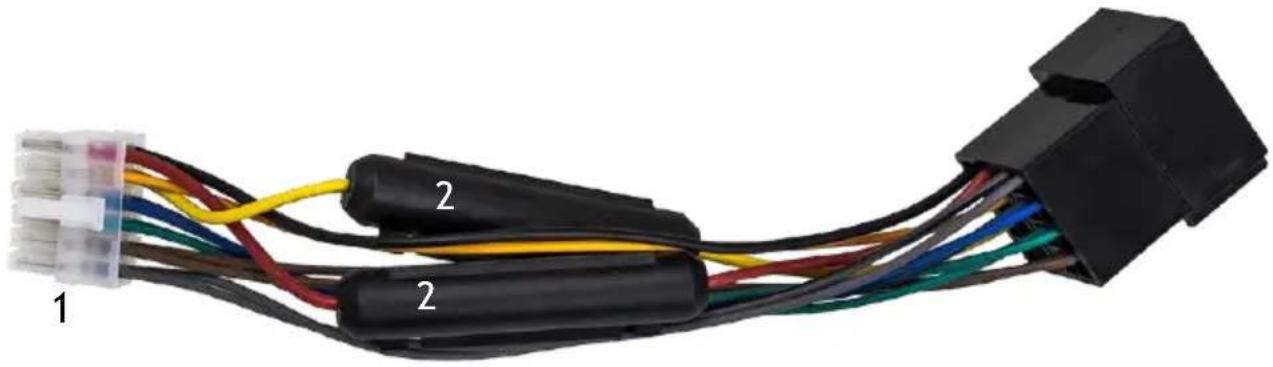
1 Terminal plug
This plug connects the ISO cable with the unit.
2 Fuses
3 ISO socket
This socket connects the ISO cable with the vehicle. The ISO cable as such serves as an extension cable for an eased connection of the unit with the vehicle, provided that your vehicle has a standardized ISO port with the appropriate pin assignment.
Common solutions
The following advices are generally valid and refer to diverse Xomax models with the similar characteristics. Please note that some articles may refer not to your model exactly and contain the description of features and functions that your model does not support.
| The description of the problem | The cause and the solution |
| The remote control is without function. | Solution 1:Please ensure that the battery film is removed. By delivery the battery is protected by a film which should be removed before usage.Solution 2:The battery could be empty. Please replace it if required.Solution 3:Please make sure that the infrared receiver (labelled with IR) on the control panel is not blocked.Note:You can test the functionality of the remote control as follows: please hold the IR transmitter towards a camera (e.g. a cell phone camera) and press any button on the remote control. If the remote control is operative you can see the infrared signal on the display of the used camera device. |
| The unit does not turn on.Poor radio reception:The radio tuner finds nobroadcaster or the reception is poor. | This problem is in most cases caused due to a wrong connection of the ISO cable.Please review the pin assignments of the ISO plug and ISO socket. Pay attention to the proper connection of the ignition- and steady plus and correct the discrepancy if required.Note:Though the design of ISO port is standardized, it's pin assignment is not and may vary. Thus in case of mismatch of connections due to different pin assignments a simple plug'n'play connection may lead to grievous errors.For problem-solving regarding the radio reception it is important to know the type of the antenna of your vehicle.Here are the possible solutions for each type of the antenna:Type 1 – passive antenna (see page 9 – wiring diagram):We recommend you to substitute the existing antenna by the larger and therefore more efficient one.Shark fin or rod antennas (under 5 cm) are definitely insufficient.Type 2 – active antenna (see page 8 – wiring diagram):The vehicle provides no current for the active antenna.In this case a phantom power is required, which provides the active antenna with the external power supply.Type 3 – active antenna with diversity system:The unit provides no current for the active antenna and has no diversity support. For this type of antenna is required the phantom power with an integrated diversity system.Note:A phantom power is not to be confused with an antenna amplifier which is far less efficient. |
| Radio stations are lost:As soon as the unit will be turned off all the stored stations and users settings will be lost. | This problem is caused due to a wrong connection of the ISO cable.Please interchange the cables for ignition plus and for steady plus (see page 10).Caution:If these wires have fuses the latter should be interchanged as well. |
Disposal of an old unit
User information regarding disposal of electric and electronic devices (private households)

natural_image
Symbol of a trash bin crossed with two crossed lines and a solid black rectangle below (no text or labels)This symbol on products or in their manuals implies that electric and electronic devices at the end of their service life should be separated from the domestic waist.
Please hand these products for recycling at municipal collection points free of charge.
The proper disposal of these products contributes to environment protection.
To find the nearest collection point or recycling yard please consult your municipal administration.
Disposal of the battery
According to the battery decree we make you aware of your obligation to dispose of empty batteries at municipal collection points.
Batteries that contain pollutants (e.g. Hg = mercury, Pb = lead, Cd = cadmium) are labelled with the symbol pictured above.
At our place you can free dispose of the empty batteries purchased at our store.
- SUPER
- Installation instructions
- SP-403M
- i
- Safety instructions and precautions 24
- Installation 26
- Installation instructions 28
- Deinstallation instructions 31
- Connection schedule - Cinch multicore 34
- Connection schedule - ISO plug 35
- ISO socket pin assignment 36
- ISO cable connections 37
- Common solutions 38
- Disposal of an old unit 40
- Disposal of the battery 40
- Safety instructions and precautions
- Handling by stop only
- Installation
- ! Regular loudness
- ! Repair of the unit
- Power supply
- Replacement of fuses
- Overheating
- ! Regular temperature
- Cleaning of the unit
- Handling the touchscreen
- Moisture
- WARNING!
- Installation steps
- Fixture of the fixation sheet
- Fixture of the installation frame
- Connecting the unit
- Fixture of the unit
- Deinstallation instructions
- Preparation of the instruments
- Loosening of the fixation nut
- Usage of the extraction keys
- Loosening of the unit
- Removing of the unit
- Removing of the installation accessories
- ISO socket pin assignment
- Port A (power supply)
- Port B (loud speakers)
- ISO cable connections
- Terminal plug
- Fuses
- ISO socket
- Common solutions
- Disposal of an old unit
- Disposal of the battery
Brand : Xomax
Model : SP-403M Super
Category : Car radio