
RolloTube DuoFern ILFS - Uncategorized RADEMACHER - Free user manual and instructions
Find the device manual for free RolloTube DuoFern ILFS RADEMACHER in PDF.


| Product Type | Tubular motor for roller shutters and awnings |
| Model Series | RolloTube I-line Radio Small and Medium |
| Item Numbers | 2740 06 65, 2740 10 65, 2760 15 65, 2760 25 65, 2760 35 65, 2760 45 65 |
| Nominal Torque | 6 / 10 / 15 / 25 / 35 / 45 Nm (depending on model) |
| No-Load Speed | 28 / 16 / 16 / 16 / 16 / 12 RPM (corresponding to torque) |
| Nominal Voltage / Frequency | 230 V / 50 Hz |
| Power Consumption | 0.53 / 0.53 / 0.64 / 0.83 / 0.86 / 0.89 A (depending on model) |
| Cable Length | 3 m |
| Motor Length (without bearing) | 485 / 485 / 487 / 546 / 546 / 546 mm (depending on model) |
| Tube Diameter | 35 / 35 / 45 / 45 / 45 / 45 mm (depending on model) |
| Protection Class | IP 44 |
| Insulation Class | H |
| Radio System | DuoFern bidirectional radio (868 MHz) |
| Max. Number of DuoFern Transmitters | 20 |
| Blockage Detection | Yes, with reversing function |
| Obstacle Detection | Yes, requires freewheel catch |
| Shutter Length Compensation | Automatic |
| End Point Setting | Automatic or manual (via set button, external switch, cord circuit device, or DuoFern transmitter) |
| Thermal Protection | Yes, automatic shut-off |
| Cyclic Duration Factor (KB) | 4 min (short-time operation) |
| Mounting | Left or right installation; click bearing or other bearing types |
| Accessories | RT ConfigTool (optional), DuoFern transmitters, cord circuit setting unit |
| Warranty | 5 years (subject to conditions) |
Frequently Asked Questions - RolloTube DuoFern ILFS RADEMACHER
User questions about RolloTube DuoFern ILFS RADEMACHER
0 question about this device. Answer the ones you know or ask your own.
Ask a new question about this device
Download the instructions for your Uncategorized in PDF format for free! Find your manual RolloTube DuoFern ILFS - RADEMACHER and take your electronic device back in hand. On this page are published all the documents necessary for the use of your device. RolloTube DuoFern ILFS by RADEMACHER.
USER MANUAL RolloTube DuoFern ILFS RADEMACHER
EN Operating and installation instructions for RADEMACHER DuoFern tubular motors 29
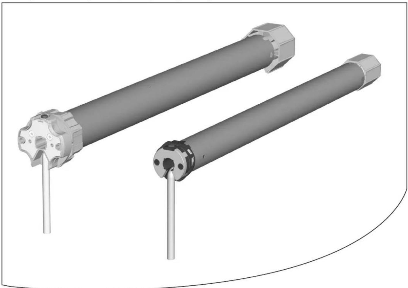
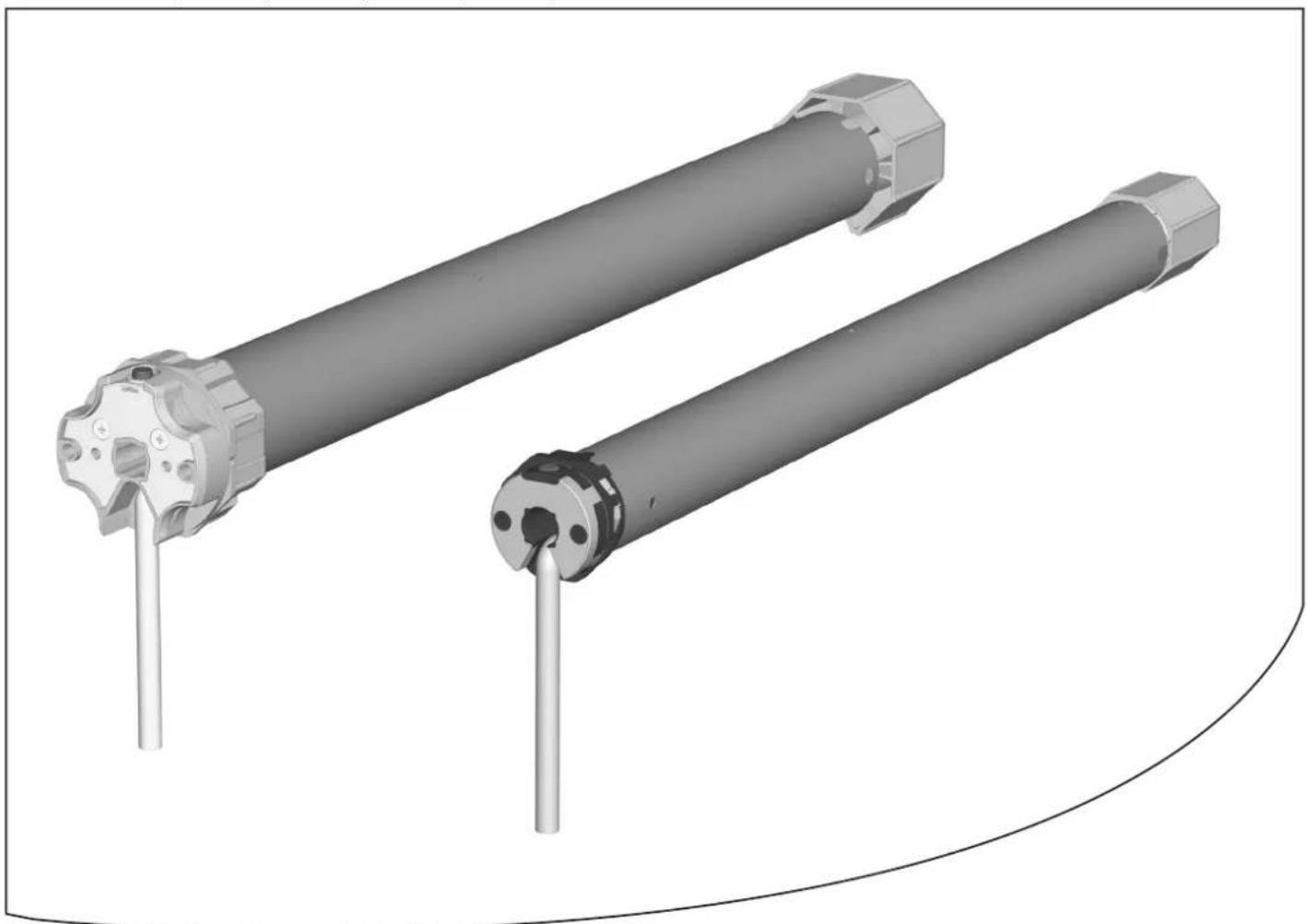
Gültig für die Serien: / Applicable for the following series: RolloTube I-line Funk Small und Medium / RolloTube I-line Radio Small and Medium
Artikelnummem / Item numbers : 2740 06 65 / 2740 10 65 / 2760 15 65 / 2760 25 65 / 2760 35 65 / 2760 45 65
natural_image
Technical illustration of two cylindrical mechanical components with flanges and pins, shown from 3D perspective (no text or symbols)3
4
5
natural_image
3D mechanical component with labeled part (10), no readable text or symbols beyond label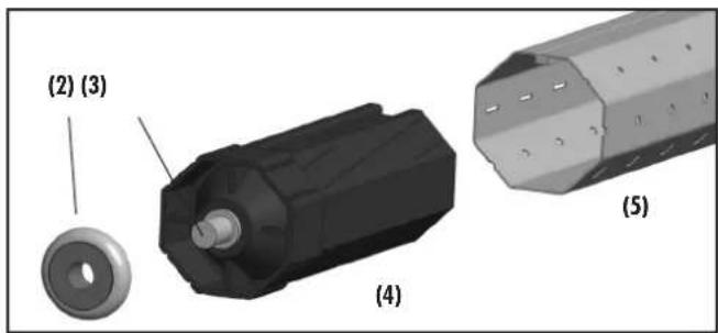
6
7
8
1.
natural_image
Illustration of a spacecraft with propellers and a star-shaped structure (no text or symbols)RolloTube I-line Funk Small
RolloTube I-line Funk Medium
natural_image
Cross-sectional diagram of a cylindrical mechanical component with a flanged end and internal features, labeled '5.d' (no text or symbols on the diagram itself)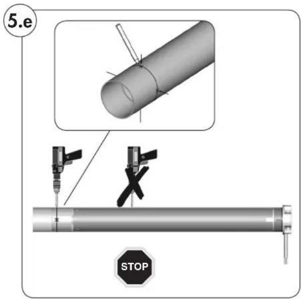
natural_image
3D rendering of a cylindrical pipe with multiple inserted pins, no text or symbols presentnatural_image
Diagram of a rolled-up sheet with multiple parallel grooves and a labeled component (21), no text or symbols present.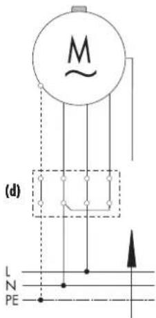
(i) = Antenne violett
WICHTIG
(i) = Antenne violett
natural_image
Electrical connector with wires and plug, labeled (22), no visible text or symbols beyond label14
service@rademacher.de
EN Operating and installation instructions for RADEMACHER DuoFern tubular motors 29
Applicable for the following series: RolloTube I-line Radio Small and Medium
Item numbers: 2740 06 65 / 2740 10 65 / 2760 15 65 / 2760 25 65 / 2760 35 65 / 2760 45 65
natural_image
Technical illustration of two cylindrical mechanical components with flanges and pins, shown from 3D perspective (no text or symbols)Please note:
Site of installation:
Serial number:
Please stick the enclosed label showing the radio code here:
With your purchase of this tubular motor, you have decided in favour of a quality product manufactured by RADEMACHER. We would like to thank you for your confidence.
RADEMACHER tubular motors have been developed with the greatest possible convenience in mind. Having applied uncompromising quality standards, and carried out thorough testing, we are proud to be able to present you with this innovative product.
It's brought to you by all the highly-qualified personnel here at RADEMACHER.

i
These instructions...

... serve to describe the installation, electrical connection and operation of RADEMACHER DuoFern tubular motors of series RolloTube I-line Radio Small and Medium.
Before you begin work, please read these instructions through completely and follow all the safety instructions.
Please store these instructions in a safe place and pass them on to any future owners.
Damage resulting from non-compliance with these instructions and safety instructions will void the guarantee. We assume no liability for any consequential damage.
i
Key to symbols

Danger of fatal electric shock
This sign warns of danger when working on electrical connections, components, etc. It requires that safety precautions be taken to protect the life and health of the person concerned.

This concerns your safety.
Please pay particular attention and carefully follow all instructions marked with this symbol.

This symbol warns of malpractices that can result in personal injury or property damage.
NOTE/IMPORTANT/CAUTION
In this way, we wish to make you aware of the following content in order to ensure optimal functionality.
Dear Customers, 30
These instructions....30
Key to symbols 30
Figures 32
Key to the overall view (Figure ①) 33
General safety instructions....34
Proper use / operational conditions 34
Incorrect use 34
Functional description 35
Blockage detection function 35
Obstacle detection function 35
Function of the shutter length compensation system 36
Function of radio code 36
Important assembly instructions 36
Installation of the tubular motor 37
Mounting the bearing (Figure ②) 37
Determine the length of the rotating union (Figure ③)....37
Mounting / dismounting the adapter (Figure ④) ......37
Mounting the catch with freewheel mechanism (Figure 4 ^a* ....38
Mounting the catch without freewheel mechanism (Figure 4b....38
Dismounting the catch (Figure 4)....38
Sliding the tubular motor into the rotating union (Figure ⑤)....39
Preparation for use of precision tubes (Figures 5a - 5f) ....39
Inserting the bearing capsule (Figure 5)....40
Mounting the motor into the bearing (Figure 6) 41
Mounting the roller shutter casing (Figures ⑦/⑧) ....41
Mounting the roller shutter stopper or an end-rail (Figure ⑨)....41
Safety information regarding the electrical connection ....42
The motor cable (Figure 10) 42
Electrical connection of the tubular motor (Figure 11) 43
Control with 1-pole switch (closer) (Figure ⑫) 43
Connection and use of the cord circuit setting unit for end point setting (Figures ^13 / ^14 ) 44
End point adjustment....44
Automatic configuration of the end points 45
Manual adjustment of end points 46
Manually setting the upper end point and automatically setting the lower end point 46
Automatically setting the upper end point and manually setting the lower end point ....47
Manual setting of upper / lower endpoint with a cord circuit setting unit or with an external switch 48
Manual setting of upper / lower endpoint with help of the set button on the tubular motor 49
Manually setting the upper / lower endpoints with DuoFern transmitters ....49
Test run / modifying the end points....49
Configuring tubular motors 50
Loading factory settings during the commissioning process ....50
What to do if... ? 51
Technical specifications 52
CE Mark and EC Conformity 52
Connecting / disconnecting DuoFern transmitters ....53
Connecting / disconnecting a DuoFern transmitter with the help of a set button .....53
Connect / disconnect the DuoFern central operating unit with the radio code ....54
Warranty conditions 56
1
3
4

5
natural_image
3D mechanical component with labeled part (10), no visible text or symbols beyond label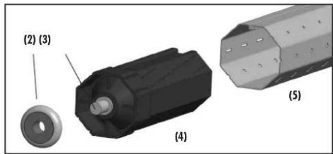
6
7
8
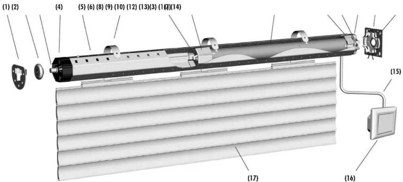
(1) Counter bearing
(2) Ball bearings
(3) Axle pin on bearing capsule
(4) Bearing capsule
(5) Rotating union
(6) Mounting spring
(7) Retaining clip
(8) Catch
(9) Tubular motor
(10) Adapter
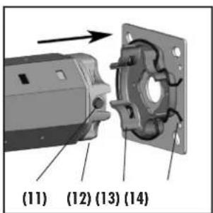
(11) Set button (transparent with LED)
(12) Drive head
(13) Drive end bearing
(14) Retainer
(15) Motor cable
(16) Controller (e.g. external switch)
(17) Roller shutter casing
(18) Limit ring
(19) Drive adapter
(20) Hook-in brackets
Please note:
Customer-specific scope of delivery
After unpacking please check the following:
◆ Check that the package contents matches the scope of delivery listed on the package.
◆ Check that the motor type corresponds to the specifications on the type plate.

Danger due to electric shock when working on all electrical systems.
The electrical connection for the tubular motor and all work on the electrical systems may only be undertaken by an authorised qualified electrician and in accordance with the connection diagrams in these instructions, see pages 42/43/44.
◆ Carry out all installation and connection work only in an isolated, deenergised state.

Mortal danger in the event of failure to observe these instructions!
◆Observe the regulations regarding installation in damp rooms.
◆ Especially observe DIN VDE 0100, parts 701 and 702 when installing in damp rooms. These regulations contain mandatory protective measures.

The use of defective equipment can lead to personal injury and damage to property (electric shocks, short circuiting).
◆Never use defective or damaged equipment.
◆Check the drive and mains cable beforehand for damage.
◆ Consult our customer service department (see page 56) in the event that you discover damage on the equipment.

According DIN EN 13659, it is necessary to determine that the movement conditions for the shutters are maintained in accordance with EN 12045.
The displacement must amount to at least 40 mm on the lower edge in the rolled-out position with a force of 150 N in the upwards direction. In doing so, it must be ensured that the extending speed of the shutters for the final 0.4 m is less than 0.2 m/s.

Potential risk to life and limb resulting from uncontrolled starting of the drive.
Never attempt to manually stop the motor/shutters in the event of uncontrolled movement. In such cases, switch off all power to the drive and take appropriate safety precautions to prevent unintentional switching on. Arrange to have the system checked by a specialist engineer.

Incorrect use leads to an increased risk of injury.
◆ Train all personnel to safely use the tubular motor.
◆Do not allow children to play with the fixed control units.
◆ Do not allow children or persons with limited capabilities to use the fixed control units or remote control systems.
For roller shutters:
◆ Watch the moving roller shutters and keep other people away from the area until the movement has completed.
◆ Undertake all cleaning work on the roller shutters with the equipment disconnected from the mains power.
For awning systems which can be operated out of sight of the operator:
◆ Awnings may not be operated if work is being carried out nearby (e.g. windows being cleaned).
For automatically actuated awnings:
◆ Awnings must be disconnected from the power supply if work is being carried out nearby.
Regular maintenance of awnings increases operational reliability.
◆ Check the awnings regularly for poor balance or damaged lines and springs.
◆Have damaged awnings repaired by a specialist firm.
Contact with the drive housing can cause burns.
◆ The tubular motor gets hot during operation. Allow the motor to cool down prior to undertaking any further work on the motor.
◆Never touch the hot drive housing.
◆ The tubular motor gets hot during operation. Allow the motor to cool down prior to undertaking any further work on the motor.
◆Never touch the hot drive housing.

Contact with the drive housing can cause burns.

Proper use / operational conditions
Only use the tubular motors for opening and closing roller shutters and awnings.
IMPORTANT
◆ The motor cable must be laid on the inside of the empty tube up to the junction box under observation of local electrical regulations.
◆Only use the manufacturer's original parts and accessories.
Only use tubular motors which correspond to the local conditions in terms of their output. Incorrectly dimensioned tubular motors can lead to damage:
◆An insufficiently dimensioned tubular motor can be damaged due to overloading.
◆An excessively dimensioned tubular motor can cause damage, for example, to the roller shutters and roller shutter casing when configuring the automatic end-point setting.
Consult a specialist dealer when selecting the tubular motor and observe our tractive force specifications on our Website: www.rademacher.de
Operating conditions
◆ A 230 V/50 Hz power supply, together with a site-provided isolating device (fuse, MCB), must be permanently available at the installation location.
The installation and operation of the DuoFern radio system and its components is only permitted for those systems and devices where a malfunction in the transmitter or receiver would not cause a danger to personnel or property or where this risk is already covered by other safety equipment.

Incorrect use
Never use the tubular motor:
For systems with increased safety-relevant requirements or where there is an increased risk of accidents. Such use would require additional safety equipment. Observe the respective statutory regulations for the installation of such systems.
Never use the DuoFern radio system or its components for:
systems with increased safety-relevant requirements or where there is an increased risk of accidents. Such use would require additional safety equipment. Observe the respective statutory regulations for the installation of such systems.
The RADEMACHER DuoFern RolloTube I-Line Radio series of tubular motors are designed for opening and closing roller shutters and awnings.
The internal DuoFern interface enables the motor to be integrated into a DuoFern radio network, making it possible to configure and control many automatic functions remotely with the help of a DuoFern transmitter (e.g. the DuoFern central operating unit).
An additional switch can be connected to the tubular motor locally in order to enable manual operation.
These tubular motors are equipped with the new Safe-Drive system for position detection, torque monitoring and obstacle detection. The drive's compact design and fully automatic end point configuration ensures for straightforward and convenient installation.
The RolloTube I-line Radio series impresses in daily operation with automatic roller shutter compensation as well as the blockage and obstacle detection system (with reversing function), ensuring maximum safety and gentle operation.
General tubular motor functions:
◆ Commissioning with a single run command. Self-learning motor with fully automatic end point configuration.
◆ Safe-Drive method for precise positioning, torque monitoring and obstacle detection.
◆Blockage and obstacle detection including reversing function.
◆ Obstacle detection can be arbitrarily configured thanks to the new snap-in FlexiClick system.
◆ Maintenance free end points thanks to automatic shutter length compensation system.
◆Quick and easy installation thanks to the new shorter design.
◆ Optionally available: Universal RT ConfigTool for individual configuration of the motor parameters.
Short description of the DuoFern radio system
The DuoFern radio system enables bidirectional data exchange between the various participants of a DuoFern radio network. All of the switching commands from the DuoFern transmitter (e.g. DuoFern central operating unit) are received and acknowledged by the DuoFern components (actuators / sensors), insofar as both devices are interconnected.
Tubular motor functions in combination with DuoFern transmitters
| DuoFern environmental sensor; Item no 3200 00 64 | |||
| DuoFern manual central operating unit; Item no 3481 00 60 | |||
| RolloTron Pro Comfort DuoFern; Item no 1523 45 11 | |||
| DuoFern manual transmitter standard; Item no 3248 03 66 | |||
| Manual control (on/off) | ●●● | ||
| AUTO/MANU - switchover | ● | ● | |
| Timed program | ● | ● | |
| Timer on / off | ● | ● | |
| Random function | ● | ● | |
| Twilight program (mornings) | ● | ||
| Twilight program (evenings) | ●●● | ||
| Darkness control(mornings and evenings) on / off | ● | ● | |
| Solar program | ● | ||
| Automatic solar function on / off | ● | ● | |
| Set solar position | ● | ||
| Wind program | |||
| Automatic wind function on / off | ● | ||
| Set direction of rotation for wind | ● | ||
| Rain program | |||
| Automatic rain function on / off | ● | ||
| Set direction of rotation for rain | ● | ||
| Set ventilation position | ● | ||
| Set direction reversal | ● | ● | |
| Start connection test | ● | ||
| End point adjustment radio controlled | ● | ● | |
| Radio code support(e. g. log on and log off with radio code) | ● | ||
Blockage detection function
The tubular motor stops and automatically shifts into the opposite direction (reversing) in the event that an obstacle is detected while opening (e.g. if a roller shutter is iced-up).
NOTE
Do not move iced-up roller shutters and rectify the fault or remove the obstacle.
Obstacle detection function
The tubular motor stops and automatically shifts briefly in the opposite direction (reversing) in the event that the roller shutter hits an obstacle while closing.
Requirements for correct obstacle detection:
◆ The catch with freewheel mechanism must be mounted (see Fig. 4.a, page 38).
◆ The roller shutter must be mounted to the rotating union with the fastening springs or with the fixed shaft connector.
◆ Roller shutters must always run vertically in the guide rails of the window.
The shutter length compensation system is active subsequent to every automatic learning process for the upper end point. Afterwards, the tubular motor no longer runs fully against the upper end point in order to protect the roller shutters and the end points.
For example, seized roller shutters can cause the automatically learned end points and runs to be changed over a period of time. In order to compensate for this, the tubular motor periodically runs automatically to the upper and lower end points (the cycle for this is configured at the factory).
NOTE
◆ The roller shutter compensation system operates automatically during normal operation, so that generally you will not notice it.
◆ If the upper end point is manually configured, then the roller shutter compensation system is inactive.
i
Function of radio code
You can control the radio tubular motor directly using the radio code in order, for example, to be also able to subsequently connect further DuoFern devices to the radio tubular motor after installation.
Once the connection has been successfully established, you can carry out actions such as setting the limit stops for a radio tubular motor.
The radio code can be found on the enclosed label:
Example:

NOTE
Time window for activation via the radio code.
After switching on the power supply, the radio code is active for a maximum 2 hours. Once this time has elapsed, activation using the radio code is no longer possible. Briefly disconnect the environmental sensor from the mains to reactivate the time window.

Important assembly instructions

IMPORTANT
◆ Check that the voltage / frequency on the type plate corresponds to local mains conditions prior to installation.
◆ All cables and equipment not required for operation of the equipment is to be removed or deactivated prior to installation of the tubular motor.
- Moving drive parts to be operated at a height under 2.5 m from the floor must be protected.
If the tubular motor is to be controlled with a switch with a default OFF setting, then the switch is to be positioned in the line of sight of the tubular motor and at a height of at least 1.5 m.
◆ The cover of the roller shutter box must be freely accessible and removable.
◆Never dismantle the stopper from the final roller shutter lamella.
Otherwise the roller shutters may slip through into the roller shutter box and be damaged.

CAUTION
Installing the tubular motor at an angle can cause the tubular motor or roller shutters to be damaged. For example, roller shutters wound at an angle can block the drive and cause damage.
◆Always ensure that the tubular motors and bearings are mounted horizontally.
◆Please ensure that the rotating union (5) and the roller shutters (17) can move down easily and freely after installation is complete.
◆ The roller shutters (17) may not run over the bearing, the bearing capsule (4) or the drive head (12) during operation.
◆ Ensure that the rotating union (5) and the fastening springs (6) of the drive (9) do not touch. They may not rub against the tubular motor (9) during operation.

For automatically actuated awnings:
◆ A minimum gap of 0.4 m to other parts in the area must be maintained when the owning is fully extended.
◆ Awnings used in an awning system must maintain a minimum height of 1.8 m.

Only use tubular motors which correspond to the local conditions in terms of their power. Incorrectly dimensioned tubular motors can lead to damage.
Incorrectly dimensioned drives and counter bearings can cause the roller shutter system to be damaged. Only use original bearings supplied by the manufacturer. Third-party drives and counter bearings must be selected in accordance with the torque specifications of the respective tubular motors.
Risk of injury in the event of incorrect installation (impact injuries and contusions).
◆ The motor can eject from the drive bearing in the event of incorrect installation/fastening. Fasten the tubular motor with the securing devices provided.
Mortal danger in the event of operation without configured end points.
◆ The end points must be configured in order to ensure safe operation. In order to do so, please refer to the corresponding chapter in this manual provided on page 44.
NOTE
The following installation instructions apply to standard installation situations in combination with RADEMACHER tubular motors and accessories.
The drive head (12) of the motor can be installed on either the right or left sides of the roller shutter box. These instructions depict the installation on the right-hand side.
Required minimum width for the roller shutter box:
Tubular motor type: all Medium
Minimum width approx.: 56 cm 67 cm

Mounting the bearing (Figure ②)

Check that the bearing is installed horizontally. Roller shutters wound at an angle can block the drive and cause damage.
1. IMPORTANT
When installed, the wound roller shutter must run vertically in the guide rails on the window.
1. First determine the position of the drive (13) and counter bearing (1) in the roller shutter box.
Wind the roller shutter casing fully onto the rotating union and measure diameter D. See figure ② in order to determine the position of the centre of the bearing to the guide rail.
2. Fasten the bearing in accordance with the bearing type and on-site conditions.
Mount the drive bearing (13) so that the set button (11) will be easily accessible and the motor cable can be laid without kinking.

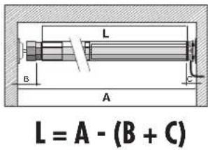
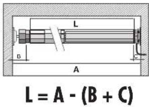
Determine the length of the rotating union (Figure ③)
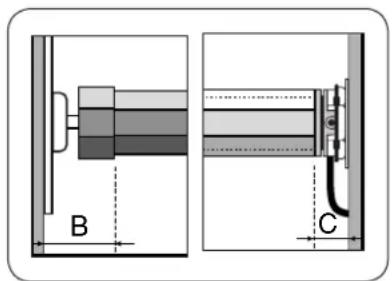
B = Counter bearing / Bearing capsule
C = Drive end bearing / motor
- Measure the wall gap of the drive bearing (13) and counter bearing (1) as shown.
- Measure the roller shutter box and calculate the required shaft length (L).
Length of the rotating union: L = A - (B + C) - Shorten the rotating union (5) to the required size.
Cut the shaft to size with a hacksaw at a right-angle. Remove the burrs from the shaft internally and externally with a file.

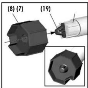
Mounting / dismounting the adapter (Figure ④)
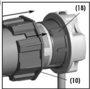
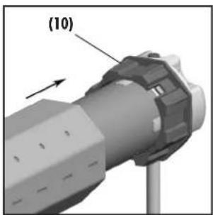
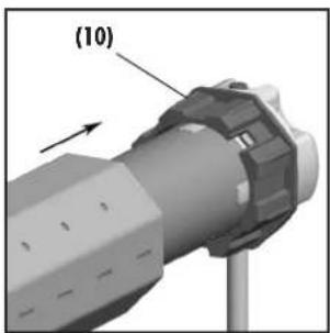
1. Mounting the adapter (10)
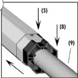
Slide the adapter (10) over the limit ring (18) on the drive head until it engages. In doing so, check the correct positioning of the groove in the adapter (10).
2. Dismantling the adapter (10)
Press the two retaining springs on the limit ring (18) downwards and pull the adapter (10) off of the limit ring (18).
*. = .supplied.state
IMPORTANT
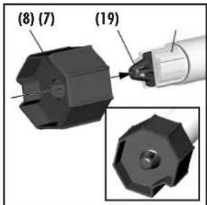
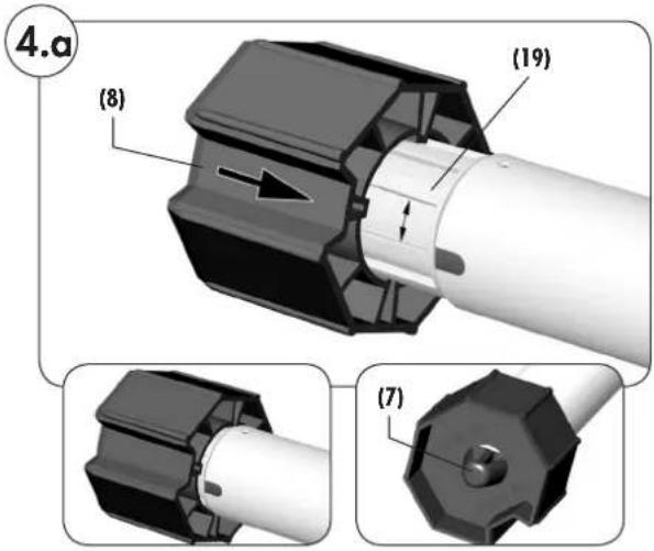
If the tubular motor is to be operated with automatic end point configuration and obstacle detection, then the catch (8) must be mounted with free-wheeling action.
- Slide the adapter (8) onto the drive adapter (19) so that it can free-wheel and so that it engages behind the retaining clip (7).
Free-wheeling is given if the catch (8) can be easily turned back and forth.

Mounting the catch without freewheel mechanism (Figure 4b)
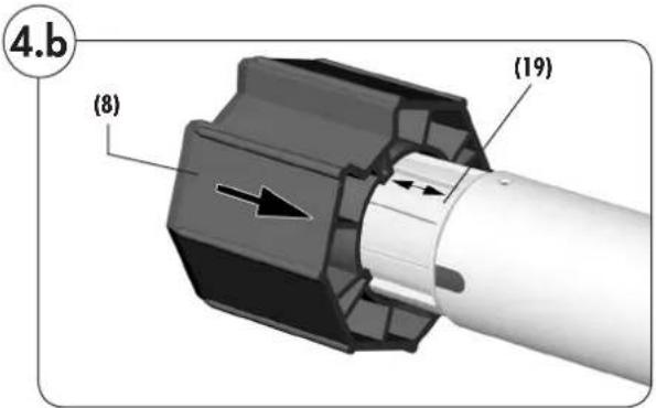
- Slide the adapter (8) onto the drive adapter (19) so that it cannot free-wheel and so that it engages behind the retaining clip (7).
NOTE
◆If the catch (8) is mounted without the freewheel mechanism, then the tubular motor will work without obstacle detection and without automatic end point configuration.
It may be necessary to mount the catch (8) without the freewheel mechanism for very lightweight roller shutters or for roller shutters which do not drop easily, in order to avoid premature switch-off.

Dismounting the catch (Figure 4c)
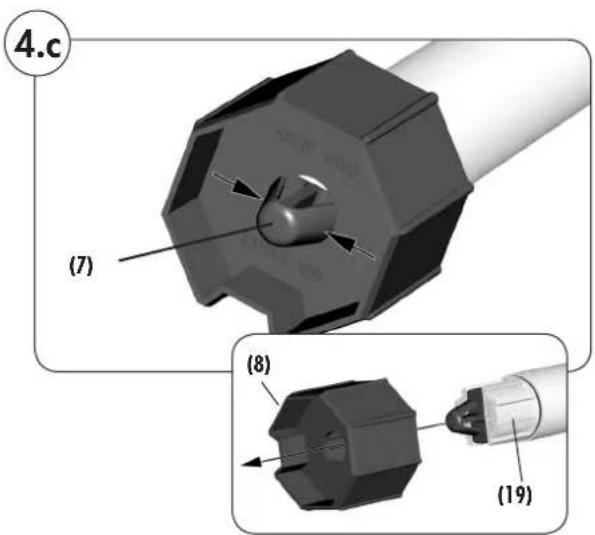
- Press the side parts of the retaining clip (7) together and pull the catch (8) off of the drive adapter (19).


natural_image
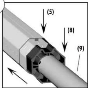
Illustration of a spacecraft with propellers and a ground vehicle (no text or symbols)Never knock the motor (9) with force into the rotating union (5).
Doing so will cause serious damage.
1.
First slide the catch (8) into the rotating union (5).
IMPORTANT
The motor (9) must have sufficient free space for rotating unions with internal felt.
- Subsequently, press the rotating union (5) fully onto the adapter (10).
IMPORTANT
In doing so, ensure that the adapter (10) does not slip off of the limit ring (18) on the drive head (12) during the assembly process. Otherwise malfunctions may occur, see page 51.

Preparation for use of precision tubes (Figures 5a - 5f)
IMPORTANT
◆Please only use precision tubes made from aluminium.
◆ The following steps can be left out when using octagonal steel shafts.
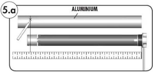
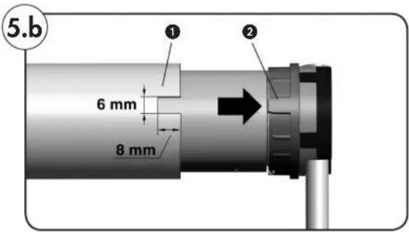
RolloTube I-line Radio Small
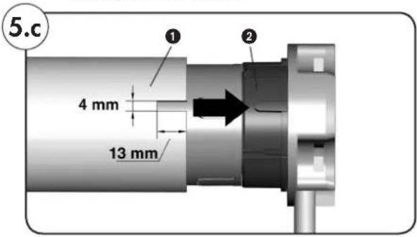
RolloTube I-line Radio Medium
- Measure the distance between the adapter (10) and the rear third of the catch (8) and mark this distance on the precision tube.
2.
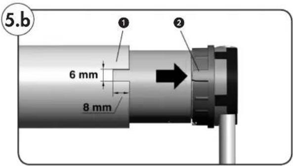
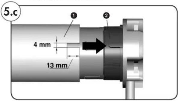
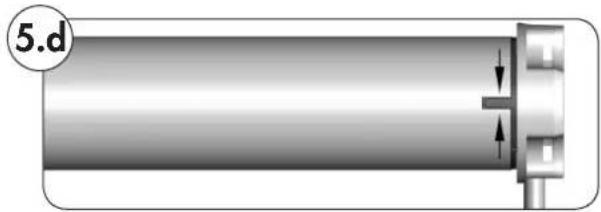
Saw a groove in the end of the precision tube ① in order that the cam ② of the adapter (10) can be pressed fully into the tube.
NOTE
◆ There may not be any play between the groove ① and the cam ②.
◆ The dimensions for the groove ① are dependent on the tubular motor type used, see figure.
natural_image
Cross-sectional diagram of a cylindrical mechanical component with a flanged end and internal features, labeled '5.d' (no text or symbols on the diagram itself)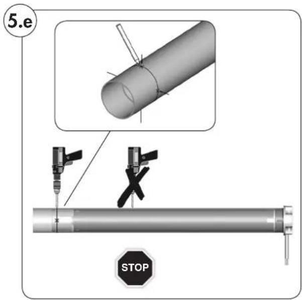
natural_image
3D rendering of a cylindrical pipe with bolted joints and a labeled section '5.f' (no text or symbols on the pipe itself)-
Slide the tubular motor into the precision tube.
-
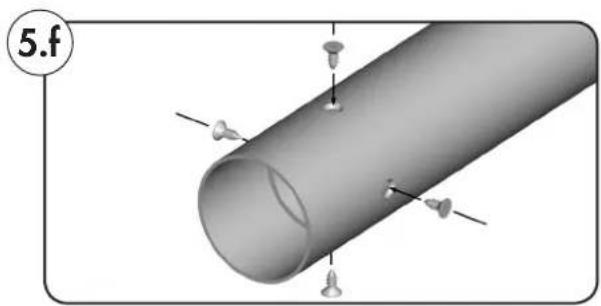
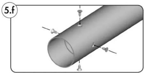
Mark the four fastening holes and subsequently drill them through the precision tube in the catch (8).
ATTENTION
◆ Never drill deeper than 10 mm into the catch (8).
◆Never drill in the area of the drive. Doing so will cause serious damage.
- Screw or rivet the precision tube to the catch (8).
Use four self-tapping sheet metal screws or four pop rivets.
Inserting the bearing capsule (Figure ⑤)
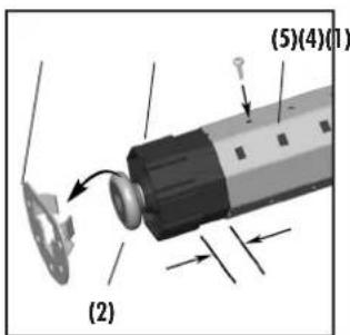
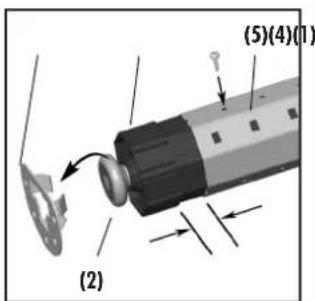
- Slide the bearing capsule (4) into the rotating union (5) and subsequently place the ball bearing (2) onto the axle pin (3).
1.
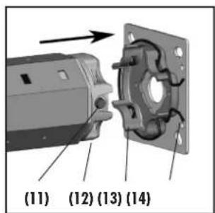
Drive bearing (as click bearing)/(13)
Press the drive head (12) lightly onto the drive bearing (13) until it engages.
NOTE
◆ The set button (11) must be easily accessible.
◆ The tubular motors can be fitted into the click bearing (13) in 4 positions. The motors can be released from the click bearing (13) at any time by means of expanding the retaining clips (14).
Drive bearing (all other bearing types)
Hook the drive head (12) into the corresponding drive bearing and secure, for example, with a cotter pin.
2.
Counter bearing (1)
Insert the other end of the rotating union (5) with the ball bearing (2) into the counter bearing (1).
In the event that you are using a different bearing to the RADEMACHER click bearing, you may need to secure the drive with a secondary cotter pin.
3.
Correct any slight inaccuracies in size by means of sliding the bearing capsule (4) in or out.
IMPORTANT
◆ Finally, secure the bearing capsule (4) with a screw.
◆ The bearing capsule (4) must be inserted at least 2/3 of its length into the rotating union (5).

Mounting the roller shutter casing (Figures g /h )
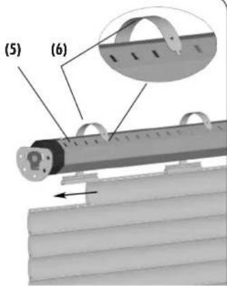
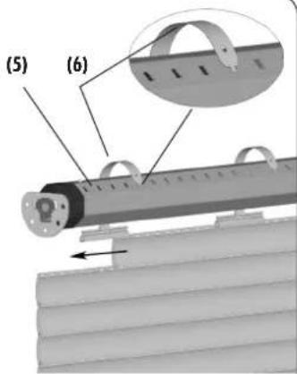
Mount the roller shutter casing (17) with fastening springs (6) (accessory) onto the rotating union (5).

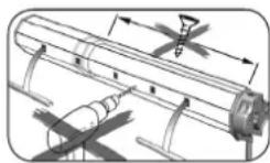
Never drill in the area of the drive or insert screws in order to secure the roller shutters.
Important
◆ Operating the equipment without a stopper may cause the roller shutters to run into the roller shutter box and be damaged.
The roller shutters must always be fitted with a stopper or end-rail.
-
Slide the fastening springs (6) onto the upper-most lamella of the roller shutter casing (17).
-
Place a fastening spring (6) every 40 cm into the rectangular holes of the rotating union (5).
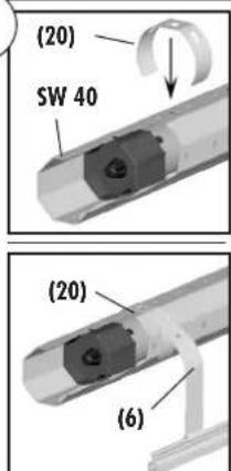
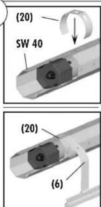
2.a For SW 40 rotating unions (with external groove) use hook-in brackets (20) in order to mount the fastening springs (6); see illustration ^8 .

Mounting the roller shutter stopper or an end-rail (Figure ⑨)
9
natural_image
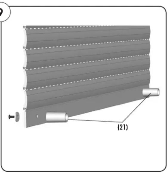
Diagram of a rolled-up mechanical component with labeled parts (21), showing layered structure and mounting base (no text or symbols beyond labels)The illustration shows a roller shutter with external stoppers (21), which are installed on the rails.
IMPORTANT
◆ Automatically setting the end points without a stopper (21) or operating the equipment without a stopper (21) may cause the roller shutters (17) to run into the roller shutter box and be damaged.
The roller shutters (17) must always be fitted with a stopper (21) or end-rail. For this reason, always mount the respective part before commissioning (see example in fig. ⑨).

Danger due to electric shock when working on all electrical systems.
◆ The electrical connection for the tubular motor and all work on the electrical systems may only be undertaken by an authorised qualified electrician and in accordance with the connection diagrams in these instructions.
◆ Disconnect all phases of the mains power supply cable and secure it to prevent any unintended reconnection.
◆Check the system for a zero-voltage status.
◆ Carry out all installation and connection work only in an isolated, zero-volts state.

Risk of short-circuit resulting from damaged cable.
◆ Lay all cables in the roller shutter box so that they cannot be damaged by moving machinery.
◆ The mains connection for the drive may only be connected with the same conduction type. Consult customer services if necessary.
Fixed-installation devices...
...must be equipped on the installation side with a circuit-breaker for each phase in accordance with DIN VDE 0700. Switches with a contact opening width of min. 3 mm can be used as circuit-breakers (e.g. power switch, power circuit breaker or residual-current-operated circuit-breaker).

Risk of short-circuit resulting from water in the event of improper cabling.
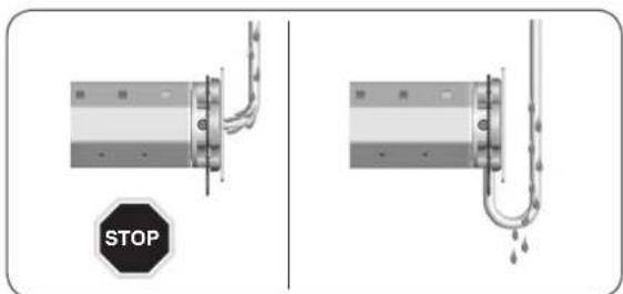
Never lay the motor cable (15) vertically upwards, as otherwise water may collect on the cable and run into the motor, possibly leading to damage. Lay the cable in a loop. The loop will cause any water on the cable to collect at the lowest point, from where it can drain off.

The motor cable (Figure 10)
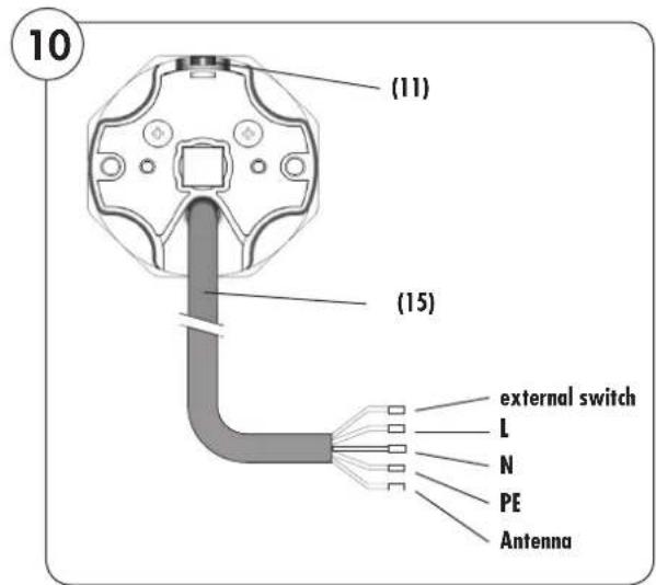
- Feed the motor cable (15) into the designated junction box or terminal box after hooking the motor in place.
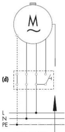
Colour scale for the motor leads (15)
◆ = external switch (white)
L = phase (black)
N = neutral (blue)
PE = earth (green / yellow)
= Antenna (violet)
(11) = Set button on tubular motor
11
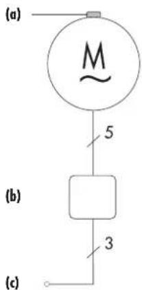
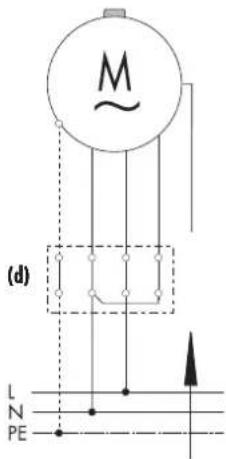
(a) = set button (11)
(b/d) = socket box
(c) = Mains 230 V/50 Hz
Pin assignment
(e) = PE green/yellow
(f) = N blue
(g) = L block
(h) = external switch white (not connected in this example)
(i) = Antenna violet
IMPORTANT
If the external switch (h) lead is not used, then it must be connected to the neutral conductor (f) (see fig. 11).

Control with 1-pole switch (closer) (Figure ⑫)
The radio tubular motor can be controlled locally by means of connecting a 1-pole switch (closer) to the "external switch" conductor.
In doing so, the switching sequence is as follows: OPEN/STOP/CLOSE/STOP, and so on.
12
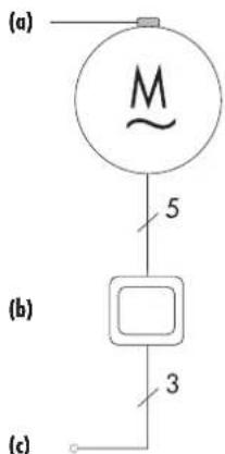
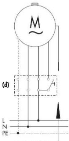
(a) = set button (11)
(b) = 1-pole switch
(c) = Mains 230 V/50 Hz
(d) = Socket box
Pin assignment
(e) = PE green/yellow
(f) = N blue
(g) = L block
(h) = external switch white *
(i) = Antenna violet
* maximum cable length between tubular motor and external switch = 10 m
IMPORTANT
If the "external switch" (h) lead is not used, then it must be connected to the neutral conductor (f) (see fig. 11).
13
natural_image
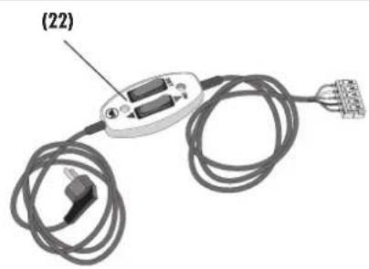
Electrical connector with wires and connectors, labeled (22), no visible text or symbols beyond label14
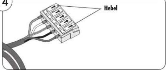
For initial installation, the roller shutter engineer can connect the motor cable (15) to a commercially available cord switch device (22) in order to configure the end points for the tubular motors.
After mounting, feed cables (e - h) for the motor cable (15) to the designated switching point (e.g. up to the switch socket).
Use the "external switch" conductor (h).
If the conductor "external switch" (h) of motor cable (15) is connected to the "SET button" of the cord circuit setting device (22), then you can use this set button to configure the end points.
NOTE
Observe the various configuration options for the end points detailed in the "End point adjustment" chapter (see below) and on the following pages.
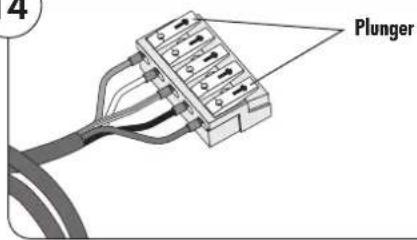
Open the terminal contacts by pressing the plungers and connect all of the wires of the motor cable (15) as follows:
Motor cable > cord circuit setting device Function > Function
L > L1 (direction of rotation 1)
External switch > set line
N > N
PE > PE
After connection is completed, the buttons of the cord circuit setting unit (22) will have the following functions:

Rocker switch in central position = motor voltage off

Rocker switch up (▲)-position = motor voltage on

SET-button = set button = roller shutters OPEN/STOP/DOWN/STOP/etc.

End point adjustment

Mortal danger due to tearing off the motor cable (15).
Ensure that the motor cable (15) is not taken up by the rotating union (15) or torn off during the configuration process.
You have various options for configuring the end points, which are described in the following section:
◆Automatic configuration of the end points.
◆Manual adjustment of end points:
- Manually setting the upper end point and setting the lower end point by means of obstacle detection.
- Setting the upper end point by means of blockage detection and manually setting the lower end point.
- Manually setting the upper end point and lower end point.
Important relationship between the configuration of the lower end point and installation of the catch.
If the catch is mounted without the freewheel mechanism, then the tubular motor will not switch off automatically, as it will not detect an obstacle and the lower end point will not be detected.
If the catch is mounted with the freewheel mechanism, then the tubular motor will switch off automatically as soon as the freewheel travel is overcome and the roller shutter lamella are closed.
IMPORTANT
◆ Operating the equipment without a stopper (21) may cause the roller shutters to run into the roller shutter box and be damaged.
◆ The roller shutters must always be fitted with a stopper (21) or end-rail.
◆ End points must be set in order to switch off the motor when they are reached for both directions of travel (up /down).
◆The tubular motor must be fully installed.
◆ There must be a suitably fixed limit (e.g. window sill) in the area of the lower end point if the end point is to be configured automatically.
◆ Disconnect the cord circuit setting unit (22) after undertaking the end point configuration and connect the tubular motor in accordance with connection diagrams (⑪ or ⑫).
◆ If the “external switch” (h) lead is not used, then it must be connected to the neutral conductor (f) (see fig. ⑪).
This procedure can be used in order to automatically search for and configure the end points for the tubular motor.
NOTE
If end points have already been configured or in the event that the end point configuration fails, you must reset the tubular motor to the factory setting (see page 50), in order to repeat the process.
Requirements for automatic configuration of the end points:
◆ The catch (8) with freewheel mechanism must be mounted (see Fig. 4.a, page 38).
IMPORTANT
◆ The tubular motor may not be disconnected from the mains during the automatic end point configuration process. The mains connection must be ensured continuously.
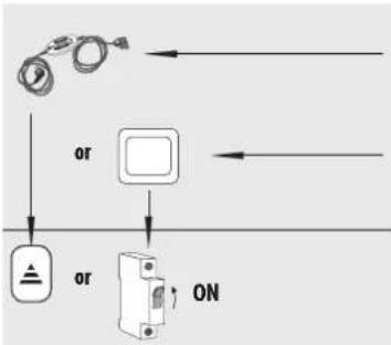
Symbols and actions when connecting a cord circuit setting unit (22) or
when connecting an external switch.
Switch on the mains power.
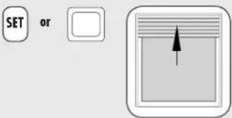
First move the roller shutters upwards.
If the tubular motor is already logged on to the DuoFern network, then the direction of travel can also be specified with DuoFern transmitters.
IMPORTANT
a) First move the roller shutter upwards when automatically adjusting the end points.
◆ If the roller shutters first move downwards, then the direction of travel must first be reversed by pressing the SET button several times or by using the external switch.
◆ The switching sequence for the SET button or the external switch is: OPEN/STOP/CLOSE/STOP, and so on.
The roller shutters will travel to the upper limit point and switch off briefly.
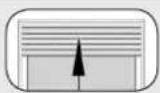
Afterwards, the tubular motor will reverse and the roller shutters will move downwards.
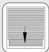
As soon as the roller shutters are fully closed, the tubular motor switches off automatically. The position of the roller shutters will be stored as the lower end point.
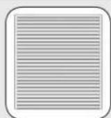
Subsequently, the roller shutters will travel up again and then switch off. This position will be stored as the upper end point.

IMPORTANT
b) The roller shutter should remain at the upper end point following automatic adjustment.
c) The end points cannot be correctly adjusted if the two conditions a) (see Point 2) and b) are not met. In this case, reset the tubular motor to its factory settings (refer to page 50) and repeat the process.
NOTE
The roller shutters will be protected during standard operations, due to the fact that they will not be tensioned by knocking against the stopper.
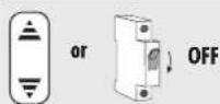
To conclude the process, disconnect the tubular motor from the power for a few seconds (e.g. by switching the cord circuit setting unit (22) toggle switch back to the central position). Subsequently, the tubular motor is ready for operation.
IMPORTANT
◆ If the "external switch" (h) lead is not used, then it must be connected to the neutral conductor (f) (see fig. ⑪).
Initial installation
For initial installation, the roller shutter engineer can carry out the end point configuration with the help of the set button (11) on the motor or with a commercially available cord switch device (22) or external switch.
Further information can be obtained from the cord switch device operating instructions.
IMPORTANT
◆ Operating the equipment without a stopper (20) may cause the roller shutters to run into the roller shutter box and be damaged.
The roller shutters must always be fitted with a stopper (20) or end-rail.
◆ End points must be set in order to switch off the motor when they are reached for both directions of travel (up /down).
◆In order to do so, the tubular motor must be fully installed.
◆ Never dismantle the mechanical stopper from the final roller shutter lamella.
◆ The roller shutter box must be opened and the set button (11) on the tubular motor must be freely accessible.
◆ Do not allow the shutters to knock against the mechanical stops and maintain a safety gap of 2 - 3 cm.

Risk of crushing injuries to the hand when working with the roller shutter box open.
Never reach into the area of the rotating union when the motor is running.

Manually setting the upper end point and automatically setting the lower end point
1.
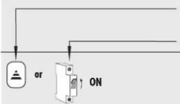
Symbols and actions when connecting a cord circuit setting unit (22)
or
when connecting an external switch.
2.
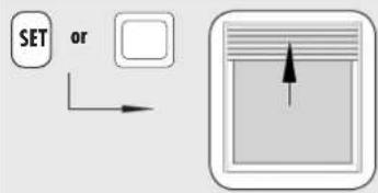
Switch on the mains power.
First move the roller shutters upwards.
If the tubular motor is already logged on to the DuoFern network, then the direction of travel can also be specified with DuoFern transmitters. This also applies to point 6.
IMPORTANT
First move the roller shutters upwards. If the roller shutters first move downwards, then the direction of travel must first be reversed by pressing the SET button several times or by using the external switch.
◆ The switching sequence for the SET button or the external switch is: OPEN/STOP/CLOSE/STOP, and so on.
3.
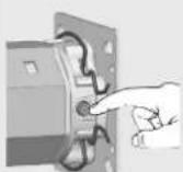
Press and hold the corresponding set button (11) until the upper end point is reached.
4
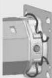
Release the set button (11) as soon as the roller shutters have reached the desired position.
The motor stops and the upper end point is stored.
5.
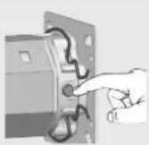
You can correct the end point in small steps by briefly pressing the set button (11).
Important
In the event that a malfunction occurs during configuration, e.g. in the event that the tubular motor only runs for a single rotation even when the set button is pressed, it is unlikely that the tubular motor is faulty. Possibly the adapter (10) has slipped off of the motor head.
Check and, if necessary, correct the positioning of the adapter (10), see pages 37 and 51.
- Finally move the roller shutters down (by briefly actuating the SET button or the external switch).
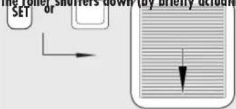
As soon as the roller shutters are fully closed, the tubular motor switches off automatically. The position of the roller shutters will be stored as the lower end point.
NOTE
In the event that the end point configuration fails, you must reset the tubular motor to the factory setting (see page 50), in order to repeat the process.
7.
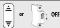
To conclude the process, disconnect the tubular motor from the power for a few seconds (e.g. by switching the cord circuit setting unit (22) toggle switch back to the central position). Subsequently, the tubular motor is ready for operation.
IMPORTANT
◆ If the "external switch" (h) lead is not used, then it must be connected to the neutral conductor (f) (see fig. ⑪).
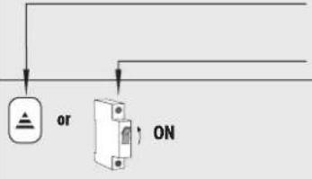 | Symbols and actions when connecting a cord circuit setting unit (22)orwhen connecting an external switch. | |
| 1. | Switch on the mains power. | |
| 2. | 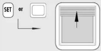 | The roller shutters will first travel to the upper stop until the tubular motor switches off automatically.If the tubular motor is already logged on to the DuoFern network, then the direction of travel can also be specified with DuoFern transmitters.IMPORTANT◆ Never interrupt the sequence while the process is running. The roller shutters must be allowed to travel up without interruption.◆ First move the roller shutters upwards. If the roller shutters first move downwards, then the direction of travel must first be reversed by pressing the SET button several times or by using the external switch.◆ The switching sequence for the SET button or the external switch is: OPEN/STOP/CLOSE/STOP, and so on. |
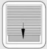 | Afterwards, the tubular motor will reverse and the roller shutters will move downwards.3. | |
| 4. | 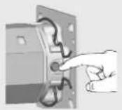 | Press and hold the set button (11) until the upper end point is reached. |
| 5. | 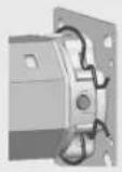 | Release the set button (11) as soon as the roller shutters have reached the desired position.The motor stops and the lower end point is stored.NOTEThese methods are useful if you want to leave the ventilation slats between the roller shutter lamella open. |
| 6. | 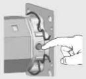 | You can correct the lower end point in small steps by briefly pressing the set button (11)IMPORTANTIn the event that a malfunction occurs during configuration, e.g. in the event that the tubular motor only runs for a single rotation even when the set button is pressed, it is unlikely that the tubular motor is faulty. Possibly the adapter (10) has slipped off of the motor head.Check and, if necessary, correct the positioning of the adapter (10), see pages 37 and 51.NOTEIn the event that the end point configuration fails, you must reset the tubular motor to the factory setting (see page 50), in order to repeat the process. |
| 7. | 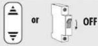 | To conclude the process, disconnect the tubular motor from the power for a few seconds (e.g. by switching the cord circuit setting unit (22) toggle switch back to the central position). Subsequently, the tubular motor is ready for operationIMPORTANT◆ If the "external switch" (h) lead is not used, then it must be connected to the neutral conductor (f) (see fig. 11). |
Manual setting of upper / lower endpoint with a cord circuit setting unit or with an external switch
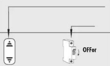 | Symbols and actions when connecting a cord circuit setting unit (22)orwhen connecting an external switch. | |
| 1. | Switch off the mains power.If a cord circuit setting unit (23) is being used, then the rocker switch must be positioned to the centre position. | |
| 2. | 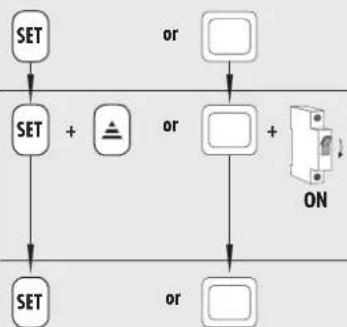 | Press and hold the SET button or the external switch. |
| 3. | Additionally switch on the mains power.After approx. 6 seconds the tubular motor starts and the roller shutters move up or down. | |
| 4. | Release the SET button as soon as the roller shutters have reached the desired position.The motor stops and the first end point is stored. | |
| 5. | 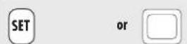 | You can correct the end point in small steps by briefly pressing the SET button.IMPORTANTIn the event that a malfunction occurs during configuration, e.g. in the event that the tubular motor only runs for a single rotation even when the SET button is pressed, it is unlikely that the tubular motor is faulty. Possibly the adapter (10) has slipped off of the motor head.Check and, if necessary, correct the positioning of the adapter (10), see pages 37 and 51.NOTEThe end points are maintained permanently even in the event of power failure. |
| 6. Switch off the | 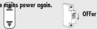 | |
| 7. | Repeat points 2 to 5 for the second end point.IMPORTANT◆ If the “external switch” (h) lead is not used, then it must be connected to theneutral conductor (f) (see fig. 11). |
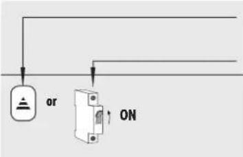
Symbols and actions when connecting a cord circuit setting unit (22)
or
when connecting an external switch.
Switch on the mains power.1.
- Move the roller shutters in the desired direction of travel. In doing so, observe the switching sequence.

◆ The switching sequence for the SET button or the external switch is: OPEN/STOP/CLOSE/STOP, and so on.
◆ If the tubular motor is already logged on to the DuoFern network, then the direction of travel can also be specified with DuoFern transmitters.
3.
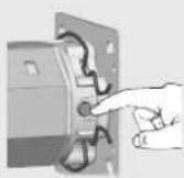
Press and hold the corresponding set button (11) until the desired end point is reached.
The roller shutters travel up or down.
4.
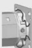
Release the set button (11) as soon as the roller shutters have reached the desired position.
The motor stops and the first end point is stored.
- You can correct the end point in small steps by briefly pressing the set button (11).
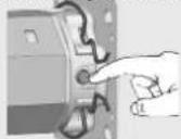
IMPORTANT
In the event that a malfunction occurs during configuration, e.g. in the event that the tubular motor only runs for a single rotation even when the Set button is pressed, it is unlikely that the tubular motor is faulty. Possibly the adapter (10) has slipped off of the motor head.
Check and, if necessary, correct the positioning of the adapter (10), see pages 37 and 51.
NOTE
The end points are maintained permanently even in the event of power failure.
6.
Repeat points 2 to 4 for the second end point.
IMPORTANT
◆ If the “external switch” (h) lead is not used, then it must be connected to the neutral conductor (f) (see fig. ⑪).

Manually setting the upper / lower endpoints with DuoFern transmitters

NOTE
The end points can also be set with a DuoFern manual transmitters or with the DuoFern central operating unit.
In order to do so, please read the operating instructions for the corresponding DuoFern transmitter.

Persons can be injured or property damaged if end points are configured using DuoFern transmitters without a direct line of sight to the roller shutters.
◆ Watch the moving roller shutters and keep other people away from the area until the movement has completed.

Test run / modifying the end points

Check the configuration and allow the roller shutters to run in both directions, until the end points switch off the motor.
Thermal protection
The tubular motors are designed for brief operation (approx. 4 mins).
If this period is exceeded, or if the equipment is switched over frequently, then the motor may heat up and the thermal protection system will shut it off.
In this case, allow the motor to cool down for 20 minutes.
Modifying the end points
Move the roller shutters back to the centre position and begin the process again.
The tubular motors can be individually configured with the help of a cord circuit setting unit (22).
The following configurations are possible.
◆Reload the factory settings.
NOTE
Additional settings can be undertaken with the optionally available RT ConfigTool. Please refer to the information on our Website (www.rademacher.de).

Loading factory settings during the commissioning process
Automatic end point configuration is available again once the factory settings have been loaded.
NOTE
We recommend undertaking these settings with two persons.
IMPORTANT
The tubular motor must previously have been disconnected from the power.
Factory settings:
| End points: No end points stored |
| Automatic adjustment of the end points: activated |
| Reversing after obstacle detection: activated |
| Reversing after blockage detection: activated |
| Shutter length compensation system: activated |
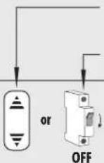
1.
Symbols and actions when connecting a cord circuit setting unit (22) or
when connecting an external switch.
2.
Switch off the mains power.
If a cord circuit setting unit (22) is being used, then the rocker switch must be positioned to the centre position.
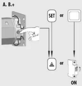
First press and hold the set button (11) on the tubular motor and subsequently press and hold the SET button on the cord circuit setting device (22) (possibly a second person carries this out).
Additionally switch on the mains power. Hold all buttons.
-
After approx. 10 seconds the tubular motor acknowledges loading of the factory settings by briefly running up
-
Release the set button (11) on the tubular motor and the SET button (or the external switch, if connected).
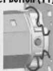
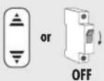
- Switch off the mains power again.
...the motor fails to start?
Possible cause:
◆The mains voltage is not available.
Solution:
◆ Check the power with a meter to ensure that the supply voltage (230 V) is available and check the wiring.
◆ Observe especially the information relating to impermissible connection types.
...The tubular motor stops after a short period of time during the configuration and test procedures?
Possible cause:
◆ The adapter (10) may have slipped off of the limit ring (18) on the drive head (12).
◆ Check that the adapter (10) sits flush with the drive head (12) and is fully inserted into the rotating union (5).
◆ Slide the adapter (10) back so that it is flush with the drive head (12) and slide the rotating union (5) fully onto the adapter (10), see Fig. ⑤. Re-adjust the end points if necessary, see page 44.
Solution:
...Automatic adjustment of the lower end point does not work.
Possible cause:
◆ The catch (8) is mounted without the freewheel mechanism.
Solution:
◆ Configure the lower end point manually, see pages 48 and 49.
...The tubular motor stops between the two end points during normal operation?
Possible cause 1:
◆ The bearing capsule (4) may not be secured with a screw to the rotating union (5) (see Fig. 6), causing the rotating union (5) to slip from the motor and the adapter (10) to come away from the limit ring (18) on the drive head (12).
Solution 1:
◆ Check for correct fitting of the bearing capsule (4) and the adapter (10). Use a self-locking bolt to secure the bearing capsule (4) to the rotating union (5) and remount the motor in accordance with the information on pages 36 - 41.
Possible cause 2:
◆The thermal protection system has triggered.
Solution 2:
◆Wait approx. 20 minutes until the motor has cooled down.
...The roller shutters stop during upward or downward travel?
Possible cause:
◆ Iced-up roller shutters or obstacle on the guide rail.
Solution:
◆ Move the roller shutters a short distance in the respective opposite direction.
◆Rectify iced-up roller shutters or obstacle.
| Motor series Medium | Small | |||||||
| 6 | 10 | 15 | 25 | 35 | 45 | [Nm] | Nominal torque: | |
| 28 | 16 | 16 | 16 | 16 | 12 | [RPM] | No-load speed: | |
| 230 | 230 | 230 | 230 | 230 | 230 | [V] | Nominal voltage: | |
| 50 | 50 | 50 | 50 | 50 | 50 | [Hz] | Frequency: | |
| 121 | 121 | 145 | 191 | 198 | 205 | [W] | Nominal power: | |
| 0.53 | 0.53 | 0.64 | 0.83 | 0.86 | 0.89 | [A] | Power consumption: | |
| 4 | 4 | 4 | 4 | 4 | 4 | [Min.] | Cyclic duration factor (KB): | |
| 5 | 5 | 5 | 5 | 5 | 5 | Number of wires: | ||
| 0.75 | 0.75 | 0.75 | 0.75 | 0.75 | 0.75 | [mm^2] | Core cross section: | |
| 3 | 3 | 3 | 3 | 3 | 3 | [m] | Cable length (standard): | |
| 32 | 32 | 32 | 32 | 32 | 32 | [R] | End switching range: (number of revolutions) | |
| H | H | H | H | H | H | Insulation class: | ||
| I | I | I | I | I | I | Protection class: | ||
| IP 44 | IP 44 | IP 44 | IP 44 | IP 44 | IP 44 | Protection class in accordance with VDE 700: | ||
| * | * | * | * | * | * | Conduction class: (* = rubber) | ||
| 485 | 485 | 487 | 546 | 546 | 546 | [mm] | Motor length without bearing: | |
| 35 | 35 | 45 | 45 | 45 | 45 | [mm] | Tube diameter: | |
CE Mark and EC Conformity
DuoFern tubular motors of series RolloTube I-line Radio Small and Medium
(item numbers.: 2740 06 65 / 2740 10 65 / 2760 15 65 / 2760 25 65 / 2760 35 65 /
2760 45 65) complies with the requirements of the current European and national
directives:

1999/5/EC R&TTE directive
2006/95/EC Low-voltage directive
2006/42/EC Machinery directive
Conformity has been verified. The corresponding declarations and documentation are available on file at the manufacturer's premises.
46414 Rhede (Germany)
Every DuoFern transmitter that is required for operation has to be assigned to the tubular motor in order that the radio tubular motor can be controlled with a DuoFern transmitter.
You can assign a maximum of 20 DuoFern transmitters, e.g. DuoFern manual central operating unit; DuoFern standard manual transmitter etc. to the radio tubular motor.
There are various ways to connect the DuoFern transmitter to the radio tubular motor or to disconnect the radio tubular motor:
- Connect / disconnect a DuoFern transmitter with the help of a set button on the tubular motor.
- Connect / disconnect a DuoFern transmitter with the help of the radio code.
- Remotely log on / log off a DuoFern transmitter with the help of the DuoFern central operating unit (please refer to the DuoFern central operating unit's operating manual).

Connecting / disconnecting a DuoFern transmitter with the help of a set button
 | Symbols and actions when connecting a cord circuit setting unit (22)orwhen connecting an external switch. | |
| 1. | 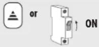 | Switch on the mains power. |
| 2. | 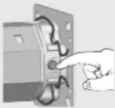 | Activate connect / disconnect mode on the radio tubular motor by briefly pressing the set button (11). |
| 3. |  Set button (11) with LED Set button (11) with LED | The radio tubular motor is briefly running up and down and the motor set button (11) lights up orange by way of acknowledgement. |
| 4. |   | Subsequently activate connect / disconnect mode on the desired DuoFern transmitter. In order to do so, please refer to the operating manual for the corresponding DuoFern transmitter.In addition, please observe the remaining time window in which you are able to connect or disconnect the DuoFern transmitter to/from the radio tubular motor. |
| 5. | The radio tubular motor acknowledges successful connection / disconnection by starting up briefly and the set button LED turns green.NOTEThe status LED lights up red if the connect / disconnect process fails, for example if :◆20 DuoFern transmitters have already been registered.◆an unsuitable device (e.g. other DuoFern actuator) is registered.◆an attempt is made to log-off a DuoFern transmitter that is not logged-on. | |
| 6. | Points 1 to 4. | If necessary, you can subsequently connect / disconnect the next DuoFern transmitter. In order to do so, repeat points 1 to 4. |
| Button | Display | Each DuoFern transmitter that is required for operation has to be assigned to the tubular motor in order that the radio tubular motor can be controlled with a DuoFern transmitter. | |
| 1. |  | 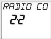 | 1. Select the “Radio Code” menu on the DuoFern central operating unit:Main menuSystem settingsRadio settingsRadio code |
| 2. |  | 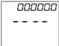 | Confirm selection. |
| 3.a | Enter the six-character radio code of the DuoFern tubular motor and confirm each figure (see enclosed sticker). | ||
| 3.b |  |  | If necessary you can jump back to the previous figure to correct it. |
| 4. |  | 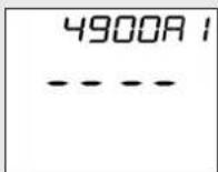 | Upon confirmation of the last figure you can activate ... |
| 5. |  | 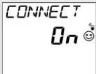 | ... connect modeordisconnect mode on the radio tubular motor. |
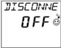 | |||
| 6. |  | 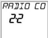 | Exit the menu. |
| 7. |  | 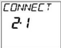 | Select menu “2 : Connect/disconnect” on the central operating unit. |
| 8. |  | 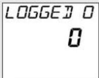 | Activate function “2 : Connect/disconnect” on the central operating unit.The number of logged on actuators is indicated on the display (e.g. 0 in the event of initial installation). |
| Button Display | |||
| 9. |  | 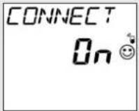 | Activate the central operating unit's "connect" or "disconnect" mode.= connect mode= disconnect modeNOTEIf disconnected, the radio tubular motor will be deleted from all of the groups in which it was previously positioned. |
| 10. |  |  | After the connection, select the following for the new actuator:a) a group numberb) a member number |
| 11. Confirm the member and group numbers. | |||
| 12. |  | 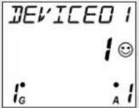 | Then enter a name for the radio tubular motor. |
| 13. | [DSXA] | 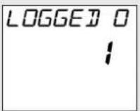 | Confirm the name.The number of logged on devices is again indicated on the display. The radio tubular motor and the DuoFern central operating unit are now either connected or disconnected. |
| 14. |  | 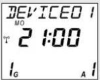 | Back to the DuoFern central operating unit's normal viewPress the key repeatedly.NOTEThe radio tubular motor can now be configured via the DuoFern central operating unit. |
RADEMACHER Geräte-Elektronik GmbH provides a 5 year guarantee for new equipment installed in accordance with the installation instructions. All construction faults, material defects and manufacturing defects are covered by the warranty.
The following are not covered by the warranty:
◆Improper mounting or installation
◆Failure to observe the mounting and operating instructions
◆Improper operation or loading
◆External influences such as impacts, knocks or weather influences
◆ Repairs and modifications carried out by third-party, unauthorised persons
◆The use of improper accessories
◆Damage caused by impermissible power surges (e.g. lightening).
◆ Malfunctions caused by frequency overlapping and other radio disturbances.
RADEMACHER shall remedy any defects, which occur within the warranty period free of charge either by repair or by replacement of the affected parts or by supply of a new replacement unit or one to the same value. There is no general extension of the original warranty period by delivery of a replacement or by repair as per the terms of the warranty.
RADEMACHER
46414 Rhede (Germany)
info@rademacher.de
www.rademacher.de
Service:
Hotline 01807 933-171*
Fax +49 2872 933-253
service@rademacher.de
* 30 seconds free of charge, subsequently 14 cents / minute from German fixed line networks and max. 42 cents / minute from German cellular networks.
- WICHTIG
- i
- These instructions...
- Key to symbols
- Danger of fatal electric shock
- This concerns your safety.
- NOTE/IMPORTANT/CAUTION
- Please note:
- After unpacking please check the following:
- Danger due to electric shock when working on all electrical systems.
- Mortal danger in the event of failure to observe these instructions!
- The use of defective equipment can lead to personal injury and damage to property (electric shocks, short circuiting).
- According DIN EN 13659, it is necessary to determine that the movement conditions for the shutters are maintained in accordance with EN 12045.
- Potential risk to life and limb resulting from uncontrolled starting of the drive.
- Incorrect use leads to an increased risk of injury.
- For roller shutters:
- For awning systems which can be operated out of sight of the operator:
- For automatically actuated awnings:
- Regular maintenance of awnings increases operational reliability.
- Contact with the drive housing can cause burns.
- Proper use / operational conditions
- Only use the tubular motors for opening and closing roller shutters and awnings.
- IMPORTANT
- Only use tubular motors which correspond to the local conditions in terms of their output. Incorrectly dimensioned tubular motors can lead to damage:
- Operating conditions
- Incorrect use
- Never use the tubular motor:
- Never use the DuoFern radio system or its components for:
- General tubular motor functions:
- Short description of the DuoFern radio system
- Blockage detection function
- NOTE
- Obstacle detection function
- Requirements for correct obstacle detection:
- Function of radio code
- The radio code can be found on the enclosed label:
- Important assembly instructions
- CAUTION
- Only use tubular motors which correspond to the local conditions in terms of their power. Incorrectly dimensioned tubular motors can lead to damage.
- Risk of injury in the event of incorrect installation (impact injuries and contusions).
- Mortal danger in the event of operation without configured end points.
- Mounting the bearing (Figure ②)
- IMPORTANT
- First determine the position of the drive (13) and counter bearing (1) in the roller shutter box.
- Fasten the bearing in accordance with the bearing type and on-site conditions.
- Determine the length of the rotating union (Figure ③)
- Mounting / dismounting the adapter (Figure ④)
- Mounting the adapter (10)
- Dismantling the adapter (10)
- Mounting the catch without freewheel mechanism (Figure 4b)
- Dismounting the catch (Figure 4c)
- 1.
- Preparation for use of precision tubes (Figures 5a - 5f)
- 2.
- ATTENTION
- Inserting the bearing capsule (Figure ⑤)
- Drive bearing (as click bearing)/(13)
- Drive bearing (all other bearing types)
- Counter bearing (1)
- 3.
- Mounting the roller shutter casing (Figures g /h )
- Mounting the roller shutter stopper or an end-rail (Figure ⑨)
- Risk of short-circuit resulting from damaged cable.
- Fixed-installation devices...
- Risk of short-circuit resulting from water in the event of improper cabling.
- The motor cable (Figure 10)
- Colour scale for the motor leads (15)
- Pin assignment
- Control with 1-pole switch (closer) (Figure ⑫)
- 13
- 14
- End point adjustment
- Requirements for automatic configuration of the end points:
- First move the roller shutters upwards.
- Initial installation
- Manually setting the upper end point and automatically setting the lower end point
- Manual setting of upper / lower endpoint with a cord circuit setting unit or with an external switch
- Manually setting the upper / lower endpoints with DuoFern transmitters
- Test run / modifying the end points
- Thermal protection
- Modifying the end points
- Loading factory settings during the commissioning process
- Possible cause:
- Solution:
- ...The tubular motor stops after a short period of time during the configuration and test procedures?
- ...Automatic adjustment of the lower end point does not work.
- Possible cause 1:
- Solution 1:
- Possible cause 2:
- Solution 2:
- ...The roller shutters stop during upward or downward travel?
- CE Mark and EC Conformity
- There are various ways to connect the DuoFern transmitter to the radio tubular motor or to disconnect the radio tubular motor:
- Connecting / disconnecting a DuoFern transmitter with the help of a set button
- The following are not covered by the warranty:
- RADEMACHER
Brand : RADEMACHER
Model : RolloTube DuoFern ILFS
Category : Uncategorized