7004 - Modem/Router Ansel - Free user manual and instructions
Find the device manual for free 7004 Ansel in PDF.


| Product Type | GSM/PSTN Fixed Wireless Terminal |
| Model | SC-355DP (7004) |
| Power Supply Input | AC 160-280V, 50/60Hz |
| Power Adapter Output | DC 7.5V / 1.5A |
| Backup Battery | Optional 6V / 4AH Lead-Acid |
| GSM Frequency Bands | 850 / 900 / 1800 / 1900 MHz (quad-band) |
| Antenna | SMA connector, 2.5 dBi omni-directional with 3 m cable |
| Interfaces | 2x RJ-11 (Phone, Line), RJ-45 (PTP/BD), DB-9 (Printer), SMA Antenna, DC power, battery terminals |
| Display | White backlight LCD for parameters and information |
| Controls | Menu, Up, Down, Enter buttons |
| Working Modes | GSM only, PSTN only, GSM/PSTN auto switch (programmable) |
| Speed Dialing | 30 groups, up to 8 digits each (GSM only) |
| GSM Prefix Numbers | 150 groups, up to 8 digits each |
| Convert Codes (VoIP) | 100 groups, up to 8 digits each |
| Block Numbers | 20 groups, up to 8 digits each |
| Free Codes | 20 groups, up to 8 digits each |
| Volume Adjustment | 5 levels for microphone and speaker (adjustable via menu or command *33XY#) |
| SIM Card | 3.3V only (not compatible with 5V or 1.8V SIM cards) |
| Telephone Connection Cable | Grey 4-pin RJ-11 cable required (max length 100 m) |
| Working Temperature | 0°C to +45°C |
| Relative Humidity | 10% to 95% |
| Color | Blue (default), Grey/Red (optional) |
| Features | Least Cost Routing, polarity reversal for metering, remote management (optional), network/BTS/SIM PIN locking (optional) |
Frequently Asked Questions - 7004 Ansel
User questions about 7004 Ansel
0 question about this device. Answer the ones you know or ask your own.
Ask a new question about this device
Download the instructions for your Modem/Router in PDF format for free! Find your manual 7004 - Ansel and take your electronic device back in hand. On this page are published all the documents necessary for the use of your device. 7004 by Ansel.
USER MANUAL 7004 Ansel
SC-355DP
User Manual
Contents
Introduction....2
Very Important Notes Before installation....2
Package list....3
- Main description....4
1.1 Features .... 4
1.2 Main panel and indicators....4
1.3 Rear panel and interfaces....5
- Work mode....6
- Installation....6
- Make a call....7
- Receive calls....7
- GSM Volume setting 7
- Other Settings....8
7.1 Work Mode setting....8
7.2 Telephone line polarity setting....8
7.3 SEND FLAG setting....8
7.4 Speed dialing setting....8
7.5 Set GSM Prefix number....9
7.6. Convert code setting....10
7.7. Block number setting 11
7.8.Free code setting....11
7.9. GSM work band (Working Frequency) setting 12
7.10. Date and Time setting....12
- Technical Parameters ....13
8.1 Power supply 13
8.2 Working environment....13
8.3 GSM parameters ....13
8.4.Antenna 13
8.5 Color 13
- Appendix ...... 14
9.1 Definition of grey cable 14
- Trouble Shooting....15
Introduction
This User's Manual mainly introduces the SC-355DP quad band GSM/PSTN Fixed Wireless Terminal which developed by our company. It includes the equipment type, performance and specification, structure and application described in details in corresponding chapters.
This User's Manual is the first edition. Our company reserves the right of upgrading the edition.
SC-355DP quad band GSM/PSTN Fixed Wireless Terminal
USER MANUAL
Version: 1.0
Date: March 3, 2008
Copyright of First Edition © 2008
All rights reserved. No part of this document may be reproduced or used in any form or by any means, including but not limited to photocopy, photograph, magnetic or other record, without the prior agreement and written permission.
Very Important Notes Before Installation
- Please make sure the area where the device is used can receive radio frequency signal.
- Please never use the equipment in an environment where explosive possibilities exist, for example: gas station, chemicals, flammable gas, gas transport car or warehouse.
- Please never use the equipment in an explosive area or a place where marked with "Turn off Wireless Transmitting Device".
- This device should be avoided in hospitals, as medical electronic equipment such as pacemakers and hearing aids are easily disturbed by it.
- There would be an electromagnetic field around the equipment, so please never put other devices which can generate interference around the equipment, for example: television, radio, computer, or magnetic memory media such as compact disks.
- Only its own suitable power adapter can be used with the device. Any other power adapters may damage this device, and this kind of damage is out of the scope of maintenance.
- If it is found that the device is unable to log into the GSM network, please make sure that the SIM card is installed correctly.
- The device does not support old SIM cards of 5V and 1.8V.
- Please make sure to use the GREY cable to connect between the "Phone" port and your telephone. Otherwise, you cannot hear the dial tone and cannot dial out any number.
- Please make sure the cable length between the device and your telephone is less than 100 meters.
- If this device is upgraded, we will not notify the user. The actual appearance and function of this product are based on the real substance. The EMI and ESD protection circuitry
does not respond to or affect the input impedance of the audio input. The audio signal has a flat frequency response between 300 and 3400 Hz. Beyond this range, the response will attenuate sharply.
Package List
Once you unpack your terminal package, please check for the following items. In case any item is found missing, please contact the provider of the terminal.
Main unit of terminal.... 1
Adapter.... 1
Antenna.... 1
Common telephone line..... 1
Grey 4-pin telephone line....2
User manual.... 1
The two grey 4-pin telephone lines are ready for connecting the telephone. If there is no grey telephone line provided with the terminal, there shall be another common telephone line. Use it to connect the telephone and terminal. If there are two grey 4-pin lines provided, they cannot be replaced by other common telephone lines.
1. Main Description
1.1 Features
Simple to install / easy to maintain. Easy access to GSM networks. High sensitivity quad band industrial module for clear voice quality. Provide up to 30mA output current for payphone connection. 2 standby channels (GSM + PSTN). 3 working modes can be selected or programmed (GSM only, PSTN only, GSM/PSTN auto switch). White backlight LCD for parameters and information display. Least Cost Routing, GSM prefix number can be programmed. Auto-prefix of local area code (programmable). Support polarity reversal signal for GSM metering. Provide menu list and 4 keys to set parameters. Support extended lead acid battery for redundancy power supply (6V, 4Ah). Network locking / BTS locking / SIM card PIN locking facility (optional). Provide RMS (remote management system) for great convenient maintenance (optional).
1.2 Main panel and indicators
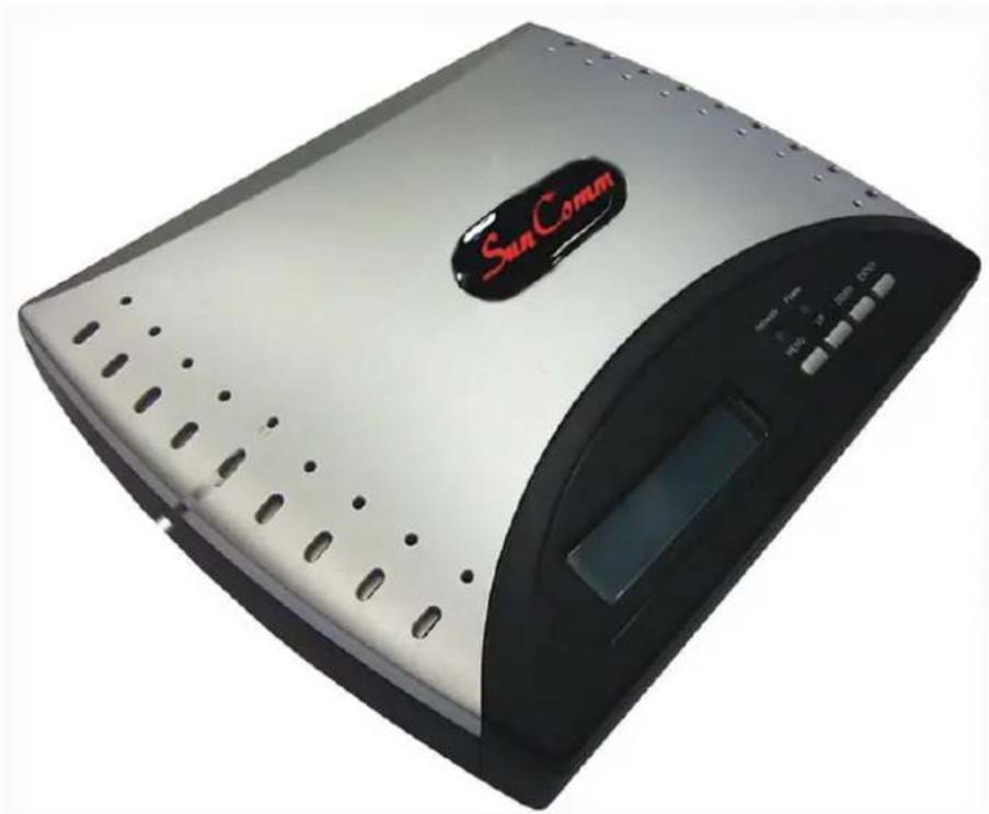
| LED and Button Color Status Description | |||
| Network A Green Flash | Flash every 1 second means connection with GSM network is OK. | ||
| Power | Green | On | Indicate the power connection is OK |
| Menu | - | - | Press this button to enter menu list or back to top menu |
| Up - - Move up the cursor or add number | |||
| Down - - Move down the cursor or reduce number | |||
| Enter - - Press this button to confirm and enter | |||
Table 1.1 LED and Button
1.3 Rear panel and interfaces
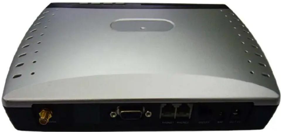
| Item | Interface | Description |
| Antenna SMA Connect with a whip antenna, 3 M RG58 cable | ||
| PTP/BD | RJ-45 | For data (tariff) download (Optional) |
| Printer | DB-9 (F) | For print out call list (Optional) |
| Line RJ-11 Connect to PSTN line | ||
| Phone | RJ-11 Connect to phone or payphone | |
| ON/OFF | - | Power switch |
| BAT | - | For extended backup accumulator battery (6V/4AH) |
| DC 7.5V | - | AC/DC power adaptor port |
Table 1.2 Interfaces
2. Work mode
This terminal has five working modes: GSM, PSTN, PSTN/GSM, and a mark will be displayed on the top right corner of the LCD after setting.
Note: If the power supply is broken or if the device is turned off, all calls will go through the PSTN line.
| Mode | Description |
| GSM Outgoing call:User can make calls through GSM network. The calls will be sent out according to setting GSM prefix numbers. The unset GSM prefix numbers will be blocked.Incoming call:User can only dial and receive calls from GSM network under this mode. | |
| PSTN Outgoing call:User can only make calls from PSTN lineIncoming call:User can only receive calls from PSTN line | |
| PSTN/GSM | Outgoing call:User can dial out either from PSTN or GSM under this mode.The dialing out call routing depends on the setting of GSM prefix numbers.The unset GSM prefix numbers will be sent out by PSTN line.Incoming call:User can receive calls from GSM or PSTN line |
3. Installation
3.1 Open the cover board on the bottom side, insert SIM card. 3.2 Connect the gray cable to the "Phone" port and telephone. 3.3 Connect the white cable to the "Line" port and PSTN line. 3.4 Connect the whip antenna and power supply adaptor. To ensure voice quality, please place the antenna more than 1.5 meters beyond the device. 3.5 Turn ON the switch of the device. If the SIM card PIN code is disabled, it takes about 10 to 50 seconds to finish the initialization program (this time depends on the signal intensity of the location). 3.6 If the SIM card PIN code is enabled, when you switch on the device, the LCD will display "Input PIN CODE". The user should input the correct PIN code through the mobile phone; otherwise, the LCD will display "SIM PIN ERROR".

Note: If the LCD displays "SIM PIN ERROR", the user can reboot the device and input the PIN code again, but the device will lock the SIM card when the input is incorrect three times. If the SIM card is locked, please put it inside your mobile phone and input the correct PUK code to release it.
4. Make a call
4.1 Lift the handset or press "Hand Free", then dial the number when you hear the dial tone. 4.2 Dial a number; the device will choose the GSM/PSTN routing automatically (Least Cost Routing function). 4.3 The user can press "#" to send out the call immediately (no PDD time).
5. Receive calls
5.1 When the device is under "PSTN/GSM" mode, the user can receive calls from either the PSTN line or GSM. 5.2 When a call is incoming, the telephone bell will ring; pick up the handset or press "Hand Free" to receive the call. 5.3 If one channel of the device is in use (under talking), it cannot receive calls from the other channel.
For example: If the device is under GSM talking, it cannot receive calls from the PSTN line until the handset is hung up.
6. GSM Volume setting
There are 5 levels that can be adjusted for microphone voice and speaker voice. The default setting is 'Microphone level: 3' and 'Speaker level: 3'.
6.1 Press the "Menu" key when the device is in standby. 6.2 Press the "UP/DOWN" key to choose "GSM VOLUME". 6.3 Pick up the handset, then press the "UP/DOWN" key to adjust the GSM volume. The range of input values is 1 to 5. 6.5 Press the "Enter" key to save and exit. 6.6 You can also adjust the volume by entering commands.
| Adjust Volume | *33XY# | The range of X or Y is from Level 1 to Level 5, X means the volume of microphone and Y means the volume of speaker. |
| Description | For example:1. *3314#To adjust the microphone volume to level 1 and to adjust the speaker volume to level 4 |
7. Other Settings
Press the "MENU" key when the device is in standby, then press the "ENTER" key to enter the submenu.
7.1 Work Mode setting
To set up the work mode, press "UP" or "DOWN" to choose "1: Work Mode". Press "ENTER" to save the setting and exit.
7.2 Telephone line polarity setting
To set the telephone line polarity mode, one option is "Normal", the other is "Reverse". This function is for payphone billing system purposes.
7.3 SEND FLAG setting
7.3.1 Press "UP" or "DOWN" to choose "3: SEND FLAG", then press "UP" or "DOWN" to select the send-out mode.
7.3.2 "PRESS # TO SEND": Allows the user to send out the dialing number immediately by pressing "#".
7.3.3 "WAIT 5S TO SEND": Does not allow the user to send out the dialing numbers immediately by pressing "#"; the calling number will be sent out after a 5-second wait (Pulse Dialing Delay). Under this mode, if the user presses the "#" key after dialing, then "#" will be sent out as a valid symbol.
7.4 Speed dialing setting
This function is available for GSM routing only. 30 groups of speed dialing numbers can be set. The maximum length of each group is 8 digits.
7.4.1 Press the "MENU" key when the device is in standby mode. Press "UP" or "DOWN" to navigate to item "4: GSM SEND LEN".
7.4.2 The LCD will display "GSM SEND LEN—XX" on the first line, where XX represents the group number. The second line shows the speed dialing list.
For example: "138 11" means that telephone numbers beginning with "138" will be sent out immediately once 11 digits are dialed.
7.4.3 Press "UP" or "DOWN" to view all speed dialing numbers. 7.4.4 Press "ENTER", and the LCD will show "ADD DIAL LEN" to add new items to the list.
Pick up the handset and input "prefix number + # + number length + #".
For example: To set telephone numbers beginning with "0755" to be sent out immediately once 12 digits are dialed, input "0755#12#". So, when dialing "075583631895", it will be sent out immediately.
7.4.5 Press "ENTER" again. The LCD will show "DEL DIAL LEN". You can delete speed dialing numbers from the list.
Pick up the handset and input "prefix number + #".
Input "***#" to delete all speed dialing numbers.
For example, to delete the number prefix "0755", simply input "0755#".
7.4.6 Press "MENU" to return to the main menu.
7.5 Set GSM Prefix Number
Set GSM prefix numbers to be sent out through the GSM network. Up to 150 groups of GSM prefix numbers can be set, with a maximum length of 8 digits per group.
7.5.1 Press "UP" or "DOWN" to select item "5: GSM DIAL CODE", then press "ENTER" to enter. 7.5.2 Press "UP" or "DOWN" to select GSM. The LCD will show "GSM CODE 001". The second line displays the GSM prefix number.
For example, if the LCD shows "GSM CODE 001" and "1860", that means telephone numbers starting with "1860" will be sent out through the GSM network.
7.5.3. Press "UP" or "DOWN" to view all GSM prefix numbers. 7.5.4. Press "ENTER" to "ADD GSM CODE" to the GSM prefix number list.
Pick up the handset, input "number prefix + #".
For example: to set telephone number which begins from “0755” to be sent out through GSM network. Just input “0755#”.
7.5.5. Press "ENTER" again. LCD will show "DEL GSM CODE". You can delete GSM prefix numbers in the list.
Picking up the handset, input "number prefix + #".
Input “***#” to delete all GSM prefix numbers.
For example, to delete number prefix “0755”, just need to input “0755#”.
7.5.6. Press "MENU" to return to main menu.
7.6. Convert code setting
Set convert codes to GSM network. It can be set 100 groups convert codes, the maximum length of each group is 8 digits.
Note: This function is used to add VoIP numbers before dialing GSM numbers.
For example: If “17951” is the VoIP gateway number for GSM operator, we can set “0 ->179510”. When user is dialing national call “0X XXXX”, GSM VoIP gateway number “17951” will be added to the dialing number automatically. So, “179510X XXXX” will be sent out.
7.6.1. Press "UP" or "DOWN" to select item "6: CONVERT CODE". 7.6.2. Press "UP" or "DOWN". LCD will show "GSM CONVERT-01". The second line shows the convert codes list. 7.6.3. Press "UP" or "DOWN" to view the entire convert codes list. 7.6.4. Press "ENTER", LCD will show "ADD GSM CONVER",
Pick up the handset, input "converted code #" + "new code #".
For example: to convert "099" to "9". Just input "099#9#".
7.6.5. Press "ENTER" again. LCD will show "DEL GSM CONVER". You can delete GSM convert codes in the list.
Pick up the handset, input "number prefix + #".
Input "***#" to delete all convert codes.
7.6.6. Press "MENU" to return to main menu.
7.7. Block number setting.
20 groups GSM block numbers can be set for the terminal, the maximum length of each group is 8 digits.
7.7.1. Press "UP" or "DOWN" to select item "7: BARRED CODE". 7.7.2. Press "ENTER", LCD will show "BARRED CODE—XX", XX means the group numbers. The second line shows block numbers. 7.7.3. Press "UP" or "DOWN" to view the entire block number list. 7.7.4. Press "ENTER", LCD will show "ADD BARRED CODE".
Pick up the handset, input "Barred code + #".
For example: to set "00" as a block number, just input "00#". That means international numbers will be blocked by GSM routing.
7.7.5. Press "ENTER" again. LCD will show "DEL BARRED CODE". You can delete block number settings in the list.
Pick up the handset, input "number prefix + #".
Input "***#" to delete all block codes.
7.7.6. Press "MENU" to return to main menu.
7.8. Free code setting.
20 groups GSM free codes can be set for the terminal, the maximum length of each group is 8 digits.
Note: When you set the GSM free numbers, you must also set them in the GSM prefix number list.
For example: If "10086" is a free number for the GSM operator, after setting "10086" in the free number list, you must also set it in the GSM prefix number list. This way, when a user dials "10086", it will be sent out through GSM as a free number.
7.8.1. Press "UP" or "DOWN" to select item "8: FREE GSM CODE". 7.8.2. Press "ENTER", the LCD will show "FREE GSM CODE—XX", where XX indicates the group number. The second line shows the free numbers. 7.8.3. Press "UP" or "DOWN" to view the entire free number list. 7.8.4. Press "ENTER", the LCD will show "ADD FREE CODE".
Pick up the handset and input "Free code + #".
For example, to set "110" as a free number, simply input "110#".
7.8.5. Press "ENTER" again. The LCD will show "DEL FREE CODE". You can delete free number settings from the list.
Pick up the handset and input "number prefix + #".
Input "***#" to delete all free codes.
7.8.6. Press "MENU" to return to the main menu.
7.9. GSM work band (Working Frequency) setting
7.9.1. Press "UP" or "DOWN" to select item "A: GSM BAND".
7.9.2. Press "ENTER", the LCD will show "GSM BAND". Press "UP" or "DOWN" to select GSMA or GSMB.
7.9.3. There are seven modes for the working frequency: GSM 850MHz, GSM 900MHz, GSM 1800MHz, GSM 1900MHz, GSM 850/1900MHz, GSM 900/1800MHz, GSM 900/1900MHz.
7.9.4. Press "ENTER" to confirm the selection; the terminal will restart automatically.
7.10. Date and Time setting
7.10.1. Press "UP" or "DOWN" to select item "B: DATE&TIME".
7.10.2. Press "ENTER". The LCD will show "DATE&TIME". The format for "Date and Time" is MM-DD-YY-HH-MM.
7.10.3. Press "UP" or "DOWN" to set the value. Press "MENU" to save the setting and exit.
8. Technical Parameters
8.1 Power supply
| AC Input voltage: | 160V to 280V |
| Power adaptor output: | DC7.5V / 1.5A |
| Backup battery: | 6V / 4AH Lead-Acid battery(Optional accessory) |
| Maximum charge current: | 600 mA |
| DC input voltage range: | 7.5V to 10V DC |
| Maximum DC current: | 700 mA (DC7.5V, external charge current) |
8.2 Working environment
| Working temperature: | 0 to +45 °C |
| Relative humidity: | 10% to 95% |
| Environment noise: | <60dB (A) |
| Atmospheric pressure: | 86 to 106 KPa |
8.3 GSM parameters
| Frequency bands: | GSM 850MHz, GSM 900MHz, GSM 1800MHz |
| (7 kinds) | GSM 1900MHz, GSM 850/1900MHz, GSM 900/1800MHz, GSM 900/1900MHz |
| Frequency stability: | < 2.5 ppm |
| Receive sensitivity: | < -100 dBm |
| Transmit power: | < 2W (850/900 MHz), < 1W (1800/1900 MHz) |
| SIM card mode: | 3.3 V |
| Antenna impedance: | 50 Ohm |
8.4. Antenna
| Gain: | 2.5dBi (omni directional) with 3 M (11.8US in.) wire |
| 5dBi whip antenna is optional | |
| 7dBi Yagi antenna is optional |
8.5 Color
| Blue (default) |
| Grey / Red (Optional) |
9. Appendix
9.1 Definition of grey cable
If you want to connect the grey cable to a 2-wire telephone/payphone, the correct connection method is shown as follows:
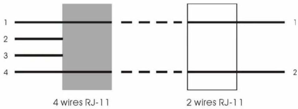
10. Troubleshooting
| Trouble phenomenon | Solving Methods |
| Can not dial number. | 1. SIM card has been locked: insert the SIM card into a mobile phone, if the card has been locked, there will display prompt in the mobile LCD which requires inputting PUK code. Input PUK code, then input a new PIN code and set the new PIN code as 1234. If the equipment has reciprocal SIM card lock function, the PIN code of the SIM card should be opened. Or the PIN code of the SIM card should be locked to avoid SIM card being locked. After unlocking the SIM card, insert the SIM card into the equipment and turn the equipment on.2. Can not detect any SIM card: Please check the contact spring of the SIM card holder or the contact point of the SIM card to see whether there is abrasion, ageing or stain in the SIM card. And then install the SIM card again.3. Bad connection of antenna or antenna rupture: please check whether the core of the antenna is well connected or change the antenna.4. Telephone setup: Please check whether the dialing system is DTMF, or whether the phone lock is opened. |
| “Network” indicator flickering fast | 1. Bad connection of antenna or antenna rupture, please check whether the core of the antenna is well connected or change the antenna.2. Weak signal. Please adjust the position of antenna and observe signal quality of LCD screen to get the best call effect |
| LCD display “Error PIN” | SIM card locked, user access be refused. Please connect with vendor or owner to unlock. |
| “Power” indicator OFF | 1. Connection problem of power adaptor or backup battery. Please check the status of power adaptor or backup battery2. The adaptor or main board is burned. Please contact with your provider |
| No dialing tone | 1. It is possible that the grey cable isn't used to connect with your telephone or payphone. You should use this special cable to connect between the terminal and telephone /payphone. The definition of the gray cable is shown in section 16.12. Bad line connection: Please check whether the electrical function of the line is ok. |
| Interference | 1. Antenna interference: Please place the antenna away from the power line and telephone line and telephone as far as possible. Antenna, power line, telephone line can not be bound together to lay out. If there is a necessary cross connect, please make it to be vertical cross connect. There should be no transmission equipment around the equipment to avoid interference between each other.2. Bad connection of crystal connector of telephone straight line and coil line, please replace them. |
| No incoming call display | 1. The incoming call display function of SIM card has not been opened: Please contact with SIM card operators to open the function.2. No incoming call display: Please change another telephone which possesses DTMF incoming call display function. |
| Voice quality bad during calling or echo can be heard | 1 Adjusting smaller volume of telephone / payphone2 Try to change a better telephone or handset3. Weak signal. Reference ““Network” indicator flickering fast” partly content |
| Only toll free number can be dialed out | It is possible the balance money not enough. Please charge money for your SIM card |
| One way conversation | 1. Failure telephone or payphone. Please check your telephone or payphone2. No metering pulse for payphone. Please contact with your provider |
| No ring when calls incoming or can not receive any incoming calls | 1. Failure telephone or payphone. Please check your telephone / payphone or change it2. Terminal set error or terminal failure. Please contact with your provider |
| Off hook and busy tone | Please check the network |
Note: Special statement:
Any result due to the action of changing the parameters of the equipment without the certification of our company has no relation with our company. And please never randomly change the SIM card to test the equipment for the users who have set the reciprocal SIM card lock function. Please use the original card to avoid unnecessary trouble caused by SIM card.
SunComm Technology Co., Ltd.
7F, No. 53, Jian Kang Rd. Chung Ho City, Taipei Hsien, Taiwan 23586
Tel: 886-2-32341496 Fax: 886-2-32341393


- CONTENTS
- INTRODUCTION
- SC-355DP QUAD BAND GSM/PSTN FIXED WIRELESS TERMINAL
- USER MANUAL
- VERY IMPORTANT NOTES BEFORE INSTALLATION
- PACKAGE LIST
- MAIN DESCRIPTION
- FEATURES
- MAIN PANEL AND INDICATORS
- REAR PANEL AND INTERFACES
- WORK MODE
- INSTALLATION
- MAKE A CALL
- RECEIVE CALLS
- GSM VOLUME SETTING
- OTHER SETTINGS
- WORK MODE SETTING
- TELEPHONE LINE POLARITY SETTING
- SEND FLAG SETTING
- SPEED DIALING SETTING
- SET GSM PREFIX NUMBER
- CONVERT CODE SETTING
- BLOCK NUMBER SETTING
- FREE CODE SETTING
- GSM WORK BAND (WORKING FREQUENCY) SETTING
- DATE AND TIME SETTING
- TECHNICAL PARAMETERS
- POWER SUPPLY
- WORKING ENVIRONMENT
- GSM PARAMETERS
- ANTENNA
- COLOR
- APPENDIX
- DEFINITION OF GREY CABLE
- TROUBLESHOOTING
- SUNCOMM TECHNOLOGY CO., LTD
Brand : Ansel
Model : 7004
Category : Modem/Router