2014 - Access Point Ansel - Free user manual and instructions
Find the device manual for free 2014 Ansel in PDF.


| Type of product | Wireless access point |
| Brand | Ansel |
| Model | 2014 |
| Connectivity | Wi-Fi 802.11 b/g/n |
| Frequency band | 2.4 GHz |
| Maximum data rate | Up to 300 Mbps |
| Ethernet ports | 1 x 10/100 Fast Ethernet LAN port |
| Antenna type | Omnidirectional internal antenna |
| Wireless security | WEP, WPA, WPA2 with encryption |
| Management interface | Web-based configuration panel |
| Power input | 12V DC 0.5A power adapter |
| Dimensions | 180 x 120 x 30 mm |
| Weight | 300 g |
| Operating temperature | 0°C to 40°C |
| Housing material | Plastic with ventilation slots |
| LED indicators | Power, LAN, Wi-Fi status |
| Reset function | Factory reset via recessed pinhole button |
| Mounting options | Desktop placement or wall mount |
| Operation modes | Access point, client, and repeater mode |
| Cleaning and maintenance | Use a soft dry cloth; keep air vents unobstructed |
| Reparability and spare parts | Standard screws allow disassembly; spare power adapter and internal antenna available through support |
| General information | Designed for home and small office wireless networking |
Frequently Asked Questions - 2014 Ansel
User questions about 2014 Ansel
0 question about this device. Answer the ones you know or ask your own.
Ask a new question about this device
Download the instructions for your Access Point in PDF format for free! Find your manual 2014 - Ansel and take your electronic device back in hand. On this page are published all the documents necessary for the use of your device. 2014 by Ansel.
USER MANUAL 2014 Ansel
Access Point & Client Bridge

User's Manual
Version: 1.1
Table of Contents
1 INTRODUCTION....5
1.1 FEATURES 5
1.2 PACKAGE CONTENTS 6
1.3 SAFETY GUIDELINES 6
1.4 SYSTEM REQUIREMENTS....6
1.5 APPLICATIONS....7
2 UNDERSTANDING THE HARDWARE....8
2.1 HARDWARE INSTALLATION....8
2.2 HARDWARE DESCRIPTION....8
2.3 MOUNTING KITS 9
2.4 IP ADDRESS CONFIGURATION....9
3 SWITCHING BETWEEN OPERATING MODES 11
3.1 LOGGING IN 11
4 ACCESS POINT OPERATING MODE 12
LOGGING IN....12
STATUS....13
MAIN 13
WIRELESS CLIENT LIST 14
SYSTEM LOG 14
SYSTEM 15
SYSTEM PROPERTIES 15
IP SETTINGS 15
SPANNING TREE SETTINGS 16
WIRELESS....17
WIRELESS NETWORK....17
WIRELESS SECURITY - WEP 17
WIRELESS SECURITY – WPA-PSK, WPA2-PSK, WPA-MIXED.... 18
WIRELESS SECURITY – WPA, WPA2 19
WIRELESS MAC FILTER 20
WIRELESS ADVANCED SETTINGS 21
MANAGEMENT 22
ADMINISTRATION 22
SNMP SETTINGS 22
BACKUP/RESTORE SETTINGS, RESET TO FACTORY DEFAULT SETTINGS 23
FIRMWARE UPGRADE 24
TIME SETTINGS....25
LOG....25
5 CLIENT BRIDGE OPERATING MODE....26
5.1 LOGGING IN 26
5.2 STATUS 27
5.2.1 MAIN.... 27
5.2.2 CONNECTION STATUS 28
5.2.3 SYSTEM LOG 28
5.3 SYSTEM 29
5.3.1 SYSTEM PROPERTIES 29
5.3.2 IP SETTINGS 29
5.3.3 SPANNING TREE SETTINGS....30
5.4 WIRELESS 31
5.4.1 WIRELESS NETWORK 31
5.4.2 WIRELESS SECURITY - WEP 32
5.4.3 WIRELESS SECURITY – WPA-PSK, WPA2-PSK 33
5.4.4 WIRELESS ADVANCED SETTINGS 33
5.5 MANAGEMENT 34
5.5.1 ADMINISTRATION....34
5.5.2 SNMP SETTINGS 35
5.5.3 BACKUP/RESTORE SETTINGS, RESET TO FACTORY DEFAULT SETTINGS 35
5.5.4 FIRMWARE UPGRADE 36
5.5.5 TIME SETTINGS 37
5.5.6 LOG....37
6 CLIENT ROUTER OPERATING MODE 39
6.1 LOGGING IN 39
6.2 STATUS 40
6.2.1 MAIN 40
6.2.2 CONNECTION STATUS 41
6.2.3 SYSTEM LOG 41
6.3 SYSTEM 42
6.3.1 SYSTEM PROPERTIES 42
6.4 ROUTER....42
6.4.1 WAN SETTINGS 42
6.4.1.1 WAN-DHCP 43
6.4.1.2 WAN-STATIC IP 44
6.4.1.3 WAN-PPPoE 45
6.4.2 VPN PASS THROUGH 46
6.5 WIRELESS 46
6.5.1 WIRELESS NETWORK 46
6.5.1.1 WIRELESS SECURITY - WEP 47
6.5.1.2 WIRELESS SECURITY – WPA-PSK, WPA2-PSK......48
6.5.2 WIRELESS ADVANCED SETTINGS 49
6.6 MANAGEMENT 50
5.5.7 ADMINISTRATION....50
5.5.8 SNMP SETTINGS....51
5.5.9 BACKUP/RESTORE SETTINGS, RESET TO FACTORY DEFAULT SETTINGS 51
5.5.10 FIRMWARE UPGRADE 52
5.5.11 TIME SETTINGS....53
5.5.12 LOG....53
APPENDIX A - SPECIFICATIONS .... 55
APPENDIX B - FCC INTERFERENCE STATEMENT....58
Revision History
| Version | Date | Notes | |
| 1.0 August 24, 2008 | Initial Version | ||
1 Introduction
EOC1650 is a long range outdoor wireless Access Point and Client Bridge that operates seamlessly in the 2.4GHz frequency spectrum. It features high transmitted output power and high receivable sensitivity. High output power and high sensitivity can extend range and coverage to reduce the roaming between Access Points to get a more stable wireless connection. It also reduces the expense of equipment in the same environment.
It supports distance range from 1km to 30km and RSSI indicator which enables the best transmit and receive signals for traffic communication. This product comes with PoE injector for building in outdoor environment easily.
To protect your wireless connectivity, it can encrypt all wireless transmissions through 64/128-bit WEP data encryption and also supports WPA/WPA2. The MAC address filter lets you select exactly which stations should have access to your network. In addition, the User Isolation function can protect the private network between client users.
The attractive design, high performance, and array of features make EOC1650 a suitable wireless solution for your residence or office.
This chapter describes the features, package contents, applications, and network configuration.
1.1 Features
Wireless
• 2.4GHz It works in 2.4GHz frequency spectrum
- High output power Transmit output power programmable for different country selections
- High Data Rate High speed transmitting rate up to 54Mbps, support large payload such as MEPG video streaming
• Multifunction application Access Point/Client Bridge/Client Router
- Long range transmitting Transmit power control and distance control (ACK timeout)
- Signal Strength LED indicators have the best transmit and receive signal for traffic communication
Networking
- Public wireless solution An AP interface that is especially useful in public areas such as hotspots and enterprise
- Signal Strength Display RF signal strength status shown LEDs of 3 colors, making network build-up easier
• QoS(WMM) Enhance performance and quality of service
Security
• 802.11i WEP, WPA, WPA2 (Encryption support TKIP/AES)
• 802.1x IEEE 802.1x Authenticator
• MAC address functions MAC address filter (AP mode)
- Station isolation
Management
- Firmware Upgrade Upgrading firmware via web browser, setting are reserved after upgrade
- Reset & Backup Reset to factory default. User can export all setting into a file via WEB
• MIB MIB I, MIB II(RFC1213)
• SNMP V1, V2c
1.2 Package Contents
Open the package carefully, and make sure that none of the items listed below are missing. Do not discard the packing materials, in case of return; the unit must be shipped in its original package.
▶ 1* 802.11b/g Long range AP/CB (EOC1650)
▶ 1* PoE injector (EPE-1212)
▶ 1* Power Adaptor
▶ 1* CD with User's Manual
▶ 1* Quick Installation Guide (QIG)
▶ 1* Metal Strap
▶ 2* Special Screw Set
▶ 1* 5dBi Dipole Antenna
▶ 2* Suction Cup
1.3 Safety Guidelines
In order to reduce the risk of fire, electric shock and injury, please adhere to the following safety guidelines.
Carefully follow the instructions in this manual; also follow all instruction labels on this device.
▶ Except for the power adapter supplied, this device should not be connected to any other adapters.
▶ Do not spill liquid of any kind on this device.
Do not place the unit on an unstable stand or table. This unit may drop and become damaged.
Do not place any hot devices close to this unit, as they may degrade or cause damage to the unit.
▶ Do not place any heavy objects on top of this unit.
Do not use liquid cleaners or aerosol cleaners. Use a soft dry cloth for cleaning.
1.4 System Requirements
The following are the minimum system requirements in order to configure the device.
▶ PC/AT compatible computer with an Ethernet interface.
▶ Operating system that supports HTTP web-browser
1.5 Applications
The wireless LAN products are easy to install and highly efficient. The following list describes some of the many applications made possible through the power and flexibility of wireless LANs:
a) Difficult-to-wire environments
There are many situations where wires cannot be laid easily. Historic buildings, older buildings, open areas and across busy streets make the installation of LANs either impossible or very expensive.
b) Temporary workgroups
Consider situations in parks, athletic arenas, exhibition centers, disaster-recovery, temporary offices and construction sites where one wants a temporary WLAN established and removed.
c) The ability to access real-time information
Doctors/nurses, point-of-sale employees, and warehouse workers can access real-time information while dealing with patients, serving customers and processing information.
d) Frequently changed environments
Show rooms, meeting rooms, retail stores, and manufacturing sites where frequently rearrange the workplace.
e) Small Office and Home Office (SOHO) networks
SOHO users need a cost-effective, easy and quick installation of a small network.
f) Wireless extensions to Ethernet networks
Network managers in dynamic environments can minimize the overhead caused by moves, extensions to networks, and other changes with wireless LANs.
g) Wired LAN backup
Network managers implement wireless LANs to provide backup for mission-critical applications running on wired networks.
h) Training/Educational facilities
Training sites at corporations and students at universities use wireless connectivity to ease access to information, information exchanges, and learning.
2 Understanding the Hardware
2.1 Hardware Installation
- Place the unit in an appropriate location after conducting a site survey.
- Plug one end of the Ethernet cable into the Network port of the PoE injector and another end into your PC/Notebook.
- Plug one end of another Ethernet cable to AP/Bridge port of the PoE injector and the other end into you cable/DSL modem (Internet)
- Insert the DC-inlet of the power adapter into the 24V port of the PoE injector and the other end into the power socket on the wall.
This diagram depicts the hardware configuration
![graph LR A["PC, Cable/DSL Modem"] -->|Ethernet| B["PoE Injector"] B -->|Ethernet| C["Access Point"] B -->|AC/DC cable| D["Power Outlet"]](/content/2026/08/1572975/images/028f9f82ce8841db0883ee1502feacecce52fac0f43dad78443e032eeb664d5f.jpg)
2.2 Hardware Description
The images below depict the front and rear panel of the Access Point / Client Bridge.

2.3 Mounting Kits
The images below depict the standard mounting kits.
Pole Mount Wall Mount Window Mount


2.4 IP Address Configuration
This device can be configured as a Bridge/Router or Access Point. The default IP address of the device is 192.168.1.1 In order to log into this device, you must first configure the TCP/IP settings of your PC/Notebook.
- In the control panel, double click Network Connections and then double click on the connection of your Network Interface Card (NIC). You will then see the following screen.
![Local Area Connection Properties General Authentication Advanced Connect using: Intel 8255x-based PCI Ethernet Adapt Configure... This connection uses the following items: Client for Microsoft Networks File and Printer Sharing for Microsoft Networks QoS Packet Scheduler Internet Protocol [TCP/IP] In…](/content/2026/08/1572975/images/8c064c705ac2438a318118d997fb084862544e6c940d63e1ce10c96be9f23897.jpg)
- Select Internet Protocol (TCP/IP) and then click on the Properties button. This will allow you to configure the TCP/IP settings of your PC/Notebook.

- Select Use the following IP Address radio button and then enter the IP address and subnet mask. Ensure that the IP address and subnet mask are on the same subnet as the device.
For Example:
PC IP address: 192.168.1.10
PC subnet mask: 255.255.255.0
- Click on the OK button to close this window, and once again to close LAN properties window.
3 Switching Between Operating Modes
This device can operate in three modes: Access Point, Client t Bridge, and Client Router. This chapter will describe how to switch between operating modes.
3.1 Logging In
- To configure the device through the web-browser, enter the IP address of the device (default: 192.168.1.1) into the address bar of the web-browser and press Enter.
- Make sure that the device and your computers are configured on the same subnet. Refer to Chapter 2 in order to configure the IP address of your computer.
■ After connecting to the IP address, the web-browser will display the login page. - Specify admin for both the user name and password.

- After logging in, you will see the graphical user interface of the device. Click on the System Properties link under the System navigation drop-down menu.

- Select and operating mode from the list (Access Point, Client Bridge, or Client Router) and then click on the Apply button.
4 Access Point Operating Mode
Logging In
- To configure the device through the web-browser, enter the IP address of the device (default: 192.168.1.1) into the address bar of the web-browser and press Enter.
- Make sure that the device and your computers are configured on the same subnet. Refer to Chapter 2 in order to configure the IP address of your computer.
- After connecting to the IP address, the web-browser will display the login page.
- Specify admin for both the user name and password.

- After logging in you will graphical user interface (GUI) of the device. The navigation drop-down menu on left is divided into four sections:
- Status: Displays the overall status, connection status, and event log.
- System: This menu includes the system properties, IP and Spanning Tree settings.
- Wireless: This menu includes status, basic, advanced, and security.
- Management: This menu includes the admin setup, SNMP, firmware upgrade, and save/restore backup.

Status
Status
- Main
- Wireless Client List
- System Log
- Click on the Status link on the navigation dropdown menu. You will then see three options: Main, Wireless Client List, and System Log. Each option is described in detail below.
Main
- Click on the Main link under the Status drop-down menu. The status that is displayed corresponds with the operating mode that is selected. Information such as system up time, firmware version, serial number, kernel version and application version are displayed in the 'System' section. LAN IP address, subnet mask, and MAC address are displayed in the 'System' section. In the 'Wireless section, the frequency, channel is displayed.
Main
| Home | Reset |
System Information
| Device Name | Access Point |
| Ethernet MAC Address | 00:02:6f:54:65:a6 |
| Wireless MAC Address | 00:02:6f:54:65:a7 |
| Country | N/A |
| Current Time | Sat Jan 1 00:41:59 UTC 2000 |
| Firmware Version | 1.0.25 |
LAN Settings
| IP Address | 192.168.1.1 |
| Subnet Mask | 255.255.255.0 |
| Default Gateway | 0.0.0.0 |
| DHCP Client | Disabled |
Current Wireless Settings
| Operation Mode | Access Point |
| Wireless Mode | IEEE 802.11b/g Mixed |
| Channel/Frequency | Current Frequency:2.412GHz (channel 01) |
| Wireless Network Name (SSID) | EnGenius |
| Security | Open System/No Encryption |
| Spanning Tree Protocol | Disabled |
| Distance | 1 Km |
Wireless Client List
- Click on the Wireless Client List link under the Status drop-down menu. This page displays the list of Clients that are associated to the Access Point.
- The MAC addresses and signal strength for each client is displayed. Click on the Refresh button to refresh the client list
| Client List | Home | Reset | |
| # | MAC Addr | RSSI | |
| 1 | 00:02:6f:01:cf.4f | 66 | |
| Refresh | |||
System Log
- Click on the System Log link under the Status drop-down menu. The device automatically logs (records) events of possible interest in its internal memory. If there is not enough internal memory for all events, logs of older events are deleted, but logs of the latest events are retained.

System
System
- System Properties
- IP Settings
- Spanning Tree Settings
- Click on the System link on the navigation drop-down menu. You will then see three options: System Properties, IP Settings, and Spanning Tree Settings. Each option is described in detail below.
System Properties
- Click on the System Properties link under the System drop-down menu. This page allows you to switch the operating mode of the device, as well as specify a name and select the operating region.

- Device Name: Specify a name for the device (this is not the SSID),
- Country/Region: Select a country from the drop-down list.
- Operating Mode: Select and operating mode. Configuration for each operating mode is described in their respective chapters.
- Click on the Apply button to save the changes.
IP Settings
- Click on the IP Settings link under the System drop-down menu This page allows you to configure the device with a static IP address or a DHCP client.

- IP Network Setting: Select Obtain an IP address automatically (DHCP) radio button if the Access Point is connected to a DHCP server. This will allow the Access
Point to pass IP addresses to the clients associated with it. You may select Specify an IP Address radio button if you would like the device to use a static IP address. In this case, you would be required to specify an IP address, subnet mask, and default gateway IP address.
IP Address: Specify an IP address
- IP Subnet Mask: Specify the subnet mask for the IP address
- Default Gateway: Specify the IP address of the default gateway.
- Click on the Apply button to save the changes.
Spanning Tree Settings
- Click on the Spanning Tree link under the System drop-down menu Spanning-Tree Protocol is a link management protocol that provides path redundancy while preventing undesirable loops in the network.

- Spanning Tree Status: Choose to enable or disable the spanning tree feature.
- Bridge Hello Time: Specify the number of seconds for the hello time.
- Bridge Max Age: Specify the number of seconds for the max age.
- Bridge Forward Delay: Specify the number of seconds for the bridge forward delay.
- Priority: Specify the number of seconds for the priority.
- Click on the Apply button to save the changes.
Wireless
Wireless
- Wireless Network
- Wireless MAC Filter
- Wireless Advanced Settings
- Click on the Wireless link on the navigation drop-down menu. You will then see four options: wireless network, wireless MAC filter, WDS link settings, and wireless advanced settings. Each option is described below.
Wireless Network
- The Wireless Network page allows you to configure the wireless mode, channel, SSID, and security settings.
Wireless Network

Wireless Setting

Wireless Security

Apply Cancel
- Wireless Mode: Depending on the type of wireless clients that are connected to the network, you may select B, G or B/G-mixed. If you are not sure about which clients will be accessing the wireless networks, it is recommended that you select B/G-mixed for the best performance.
- Channel: Select a channel from the drop-down list. The channels available are based on the country's regulation.
Wireless Security - WEP
- Security Mode: Select WEP from the drop-down list if your wireless network uses WEP encryption. WEP is an acronym for Wired Equivalent Privacy, and is a security protocol that provides the same level of security for wireless networks as for a wired network.

- Authentication Type: Select an authentication method. Options available are Open Key, Shared Key. An open system allows any client to authenticate as long as it conforms to any MAC address filter policies that may have been set. All authentication packets are transmitted without encryption. Shared Key sends an unencrypted challenge text string to any device attempting to communicate with the Access Point. The device requesting authentication encrypts the challenge text and sends it back to the Access Point. If the challenge text is encrypted correctly, the Access Point allows the requesting device to authenticate. It is recommended to select Auto if you are not sure which authentication type is used.
- Input Type: Select Hex or ASCII from the drop-down list
- Key Length: Select a key format from the drop-down list. 64bit-hex keys require 10 characters, where as 128-bit keys require 26 characters. A hex key is defined as a number between 0 through 9 and letter between A through F and a through f.
- Default Key: You may use up to four different keys for four different networks. Select the current key that will be used.
Key 1-4: You may enter four different WEP keys. - Click on the Apply button to save the changes.
Wireless Security – WPA-PSK, WPA2-PSK, WPA-Mixed
- Security Mode: Select WPA-PSK, WPA2-PSK, or WPA-Mixed from the drop-down list if your wireless network uses WPA pre-shared key.
Wireless Setting

Wireless Security

Apply
Cancel
- Encryption: Select TKIP or AES from the drop-down list if your wireless network uses this encryption. WPA (Wi-Fi Protected Access) was designed to improve upon the security features of WEP (Wired Equivalent Privacy). The technology is designed to work with existing Wi-Fi products that have been enabled with WEP. WPA provides improved data encryption through the Temporal Integrity Protocol (TKIP), which scrambles the keys using a hashing algorithm and by adding an integrity checking feature which makes sure that keys haven't been tampered with.
- Passphrase: Specify a passphrase that is shared amongst the Access Points and clients.
- Group Key Update Interval: Specify the number of seconds after which the Access Point will probe the client for the passphrase.
- Click on the Apply button to save the changes.
Wireless Security – WPA, WPA2
- Security Mode: Select WPA or WPA2 from the drop-down list if your wireless network uses WPA. WPA (Wi-Fi Protected Access) was designed to improve upon the security features of WEP (Wired Equivalent Privacy). The technology is designed to work with existing Wi-Fi products that have been enabled with WEP. WPA provides improved data encryption through the Temporal Integrity Protocol (TKIP), which scrambles the keys using a hashing algorithm and by adding an integrity checking feature which makes sure that keys haven't been tampered with.
Wireless Setting
| Wireless Mode | 802.11b/g Mixed (2.4GHz/54Mbps) | |
| Channel / Frequency | Ch1-2.412GHz | |
| SSID | EnGenius | (1 to 32 characters) |
| Suppressed SSID | ||
| Station Separation | Enable | Disable |
Wireless Security
| Security Mode | WPA |
| Encryption | Auto |
| Radius Server | 0.0.0.0 |
| Radius Port | 1812 |
| Radius Secret | secret |
| Group Key Update Interval | 3600 seconds(30~3600, 0: disabled) |
Apply Cancel
- Encryption: Select TKIP or AES from the drop-down list if your wireless network uses this encryption.
- RADIUS IP Address: Enter the IP address of the RADIUS server.
- RADIUS Port: Enter the port number of the RADIUS server. The default is usually 1812.
- RADIUS Secret: Enter the shared password of the RADIUS server.
- Group Key Update Interval: Specify the number of seconds after which the Access Point will probe the client for the secret.
- Click on the Apply button to save the changes.
Wireless MAC Filter
- Click on the Wireless MAC Filter link under the Wireless menu. On this page you can filter the MAC address by allowing or blocking access the network.

- ACL (Access Control) Mode: You may choose to Disable, Allow Listed, or Deny Listed MAC addresses from associating with the network. By selecting Allow MAC
in the List, only the address listed in the table will have access to the network; all other clients will be blocked. On the other hand, selected Deny MAC in the List, only the listed MAC addresses will be blocked from accessing the network; all other clients will have access to the network.
- MAC Address: Enter the MAC address.
- This table lists the blocked or allowed MAC addresses; you may delete selected MAC address or delete all the addresses from the table by clicking on the Delete button.
- Click on the Apply button to save the changes.
Wireless Advanced Settings
- Click on the Wireless Advanced Settings link. On this page you can configure the advanced settings to tweak the performance of your wireless network. Options available are: data rate, transmit power, fragmentation threshold, RTS threshold, protection mode and distance.
Wireless Advanced Settings


Apply
Cancel
- Data Rate: If you would like to force a data rate, you may select one from the dropdown list. However, for best performance it is recommended to use the Auto setting.
- Transmit Power: You may have the different application distance of the device by selecting a value from the drop-down list. This feature can be helpful in restricting the coverage area of the wireless network.
- Fragment: Packets over the specified size will be fragmented in order to improve performance on noisy networks.
- RTS Threshold: Packets over the specified size will use the RTS/CTS mechanism to maintain performance in noisy networks and preventing hidden nodes from degrading the performance.
- Protection Mode: If your wireless network is using both 802.11b and 802.g devices then it is recommended to enable this feature so that the 802.11b devices will not degrade the performance of 802.11g devices.
- WMM: Enable wireless Quality of Service
- Distance (1-30km): Specify a distance between 1 and 30Km.
- Click on the Apply button to save the changes.
Management
Management
- Administration
SNMP Settings - Backup/Restore Settings
- Firmware Upgrade
- Time Settings
Log
- Click on the Management link on the navigation drop-down menu. You will then see seven options: administration, SNMP settings, backup/restore settings, firmware upgrade, time settings, and log. Each option is described below.
Administration
- Click on the Administration link under the Management menu. This option allows you to create a user name and password for the device. By default, this device is configured without a user name and password admin. For security reasons it is highly recommended that you create a new user name and password.

■ Name: Specify a user name into the first field.
- Password: Specify a password into this field and then re-type the password into the Confirm Password field.
- Click on the Apply button to save the changes.
SNMP Settings
- Click on the SNMP Settings link under the Management menu. This option allows you to assign the contact details, location, and community name and trap settings for SNMP. This is a networking management protocol used to monitor network-attached devices. SNMP allows messages (called protocol data units) to be sent to various parts of a network. Upon receiving these messages, SNMP-compatible devices (called agents) return data stored in their Management Information Bases.

- SNMP Enable/Disable: Choose to enable or disable the SNMP feature.
- Contact: Specify the contact details of the device.
- Location: Specify the location of the device.
- Read-Only Community Name: Specify the password for access the SNMP community for read only access.
- Read-Write Community Name: Specify the password for access to the SNMP community with read/write access.
- Send SNMP Trap: Specify the IP address of the computer that will receive the SNMP traps.
- Trap Community Name: Specify the password for the SNMP trap community.
- Click on the Apply button to save the changes.
Backup/Restore settings, Reset to factory default settings
- Click on the Backup/Restore Setting link under the Management menu. This option is used to save the current settings of the device in a file on your local disk or load settings on to the device from a local disk. This feature is very handy for administrators who have several devices that need to be configured with the same settings.

- Save a copy of the current settings: Click on the Backup button to save the current configuration.
- Restore saved settings from a file: Once a file has been backed up, you may restore it by clicking on the Browse button to select the file, and then the Restore button.
- Revert to factory default settings: Click on the Factory Default Settings button to reset the device to the default settings. Please wait while the device restart and then access the device using the default IP address: 192.168.1.1
System Rebooting...
Rebooting, Please wait...
Click here when AP is ready
Firmware Upgrade
- Click on the Upgrade Firmware link under the Management menu. This page is used to upgrade the firmware on the device. Make sure that downloaded the appropriate firmware from your vendor.

- Click on the Browse button and then select the appropriate firmware and then click on the Upgrade button.
Note: The upgrade process may take about 1 minute to complete. Do not power off the device during this process as it may crash the device and make it unusable. The device will restart automatically once the upgrade is complete.
Time Settings
- Click on the Time Settings link under the Management menu. This page allows you to configure the time on the device. You may do this manually or by connecting to a NTP server.

■ Manually Set Date and Time: Specify the date and time
- Automatically Get Date and Time: Select the time zone from the drop down list and then specify the IP address of the NTP server.
- Click on the Apply button to save the changes.
Log
- Click on the Log link under the Management menu. The Log page displays a list of events that are triggered on the Ethernet and Wireless interface. This log can be referred when an unknown error occurs on the system or when a report needs to be sent to the technical support department for debugging purposes.

- Syslog: Choose to enable or disable the system log.
- Log Server IP Address: Specify the IP address of the server that will receive the system log.
- Local Log: Choose to enable or disable the local log.
- Click on the Apply button to save the changes.
5 Client Bridge Operating Mode
5.1 Logging In
- To configure the device through the web-browser, enter the IP address of the device (default: 192.168.1.1) into the address bar of the web-browser and press Enter.
- Make sure that the device and your computers are configured on the same subnet. Refer to Chapter 2 in order to configure the IP address of your computer.
- After connecting to the IP address, the web-browser will display the login page.
- Specify admin for both the user name and password.

■ After logging in you will graphical user interface (GUI) of the device. The navigation drop-down menu on left is divided into four sections:
- Status: Displays the overall status, connection status, and event log.
- System: This menu includes the system properties, IP and Spanning Tree settings.
- Wireless: This menu includes status, basic, advanced, and security.
- Management: This menu includes the admin setup, SNMP, firmware upgrade, and save/restore backup.
5.2 Status
Status
- Main
- Connection Status
- System Log
- Click on the Status link on the navigation drop-down menu. You will then see three options: Main, Connection Status, and System Log. Each option is described in detail below.
5.2.1 Main
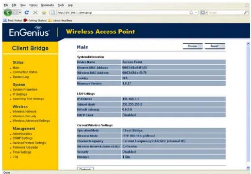
- Click on the Main link under the Status drop-down menu. The status that is displayed corresponds with the operating mode that is selected. Information such as system up time, firmware version, serial number, kernel version and application version are displayed in the 'System' section. LAN IP address, subnet mask, and MAC address are displayed in the 'System' section. In the 'Wireless section, the frequency, channel is displayed.
| Main | Home | Reset |
System Information
| Device Name | Access Point |
| Ethernet MAC Address | 00:02:6f:e0:01:95 |
| Wireless MAC Address | 00:02:6f:be:f2:70 |
| Country | N/A |
| Firmware Version | 1.0.17 |
LAN Settings
| IP Address | 192.168.1.1 |
| Subnet Mask | 255.255.255.0 |
| Default Gateway | 0.0.0.0 |
| DHCP Client | Disabled |
Current Wireless Settings
| Operation Mode | Client Bridge |
| Wireless Mode | IEEE 802.11b/g Mixed |
| Channel Frequency | Current Frequency:2.422GHz (channel 03) |
| Wireless Network Name (SSID) | EnGenius |
| Security | Disabled |
| Distance | 1 Km |
5.2.2 Connection Status
- Click on the Connection Status link under the Status drop-down menu. This page displays the current status of the network, including network type, SSID, BSSID, connection status, wireless mode, current channel, security, data rate, noise level and signal strength.
| Connection Status | Home | Reset | |
| Network Type | Client Bridge | ||
| SSID | EnGenius | ||
| BSSID | N/A | ||
| Connection Status | N/A | ||
| Wireless Mode | N/A | ||
| Current Channel | N/A | ||
| Security | N/A | ||
| Tx Data Rate(Mbps) | N/A | ||
| Current noise level | N/A | ||
| Signal strength | N/A | ||
5.2.3 System Log
- Click on the System Log link under the Status drop-down menu. The device automatically logs (records) events of possible interest in its internal memory. If there is not enough internal memory for all events, logs of older events are deleted, but logs of the latest events are retained.

5.3 System
System
- System Properties
IP Settings - Spanning Tree Settings
- Click on the System link on the navigation drop-down menu. You will then see three options: System Properties, IP Settings, and Spanning Tree Settings. Each option is described in detail below.
5.3.1 System Properties
- Click on the System Properties link under the System drop-down menu. This page allows you to switch the operating mode of the device, as well as specify a name and select the operating region.

■ Device Name: Specify a name for the device (this is not the SSID),
- Country/Region: Select a country from the drop-down list.
- Operating Mode: Select and operating mode. Configuration for each operating mode is described in their respective chapters.
- Click on the Apply button to save the changes.
5.3.2 IP Settings
- Click on the IP Settings link under the System drop-down menu This page allows you to configure the device with a static IP address or a DHCP client.

- IP Network Setting: Select Obtain an IP address automatically (DHCP) radio button if the Access Point is connected to a DHCP server. This will allow the Access Point to pass IP addresses to the clients associated with it. You may select Specify an IP Address radio button if you would like the device to use a static IP address. In this case, you would be required to specify an IP address, subnet mask, and default gateway IP address.
IP Address: Specify an IP address - IP Subnet Mask: Specify the subnet mask for the IP address
- Default Gateway: Specify the IP address of the default gateway.
- Click on the Apply button to save the changes.
5.3.3 Spanning Tree Settings
- Click on the Spanning Tree link under the System drop-down menu Spanning-Tree Protocol is a link management protocol that provides path redundancy while preventing undesirable loops in the network.

- Spanning Tree Status: Choose to enable or disable the spanning tree feature.
- Bridge Hello Time: Specify the number of seconds for the hello time.
- Bridge Max Age: Specify the number of seconds for the max age.
- Bridge Forward Delay: Specify the number of seconds for the bridge forward delay.
- Priority: Specify the number of seconds for the priority.
- Click on the Apply button to save the changes.
5.4 Wireless
Wireless
- Wireless Network
- Wireless Security
- Wireless Advanced Settings
- Click on the Wireless link on the navigation drop-down menu. You will then see three options: wireless network, wireless security, and wireless advanced settings. Each option is described below.
5.4.1 Wireless Network
- The Wireless Network page allows you to configure the wireless mode, channel, SSID, and security settings.

- Wireless Mode: Depending on the type of wireless clients that are connected to the network, you may select B, G, or B/G-mixed. If you are not sure about which clients will be accessing the wireless networks, it is recommended that you select B/G-mixed for the best performance.
- SSID: The SSID is a unique named shared amongst all the points of the wireless network. The SSID must be identical on all points of the wireless network and cannot exceed 32 characters. You may specify an SSID or select one from the Site Survey.
- Site Survey: Click on the Site Survey button in order to scan the 2.4GHz frequency for devices that broadcast their SSID. Click on the BSSID link to connect to the Access Point. Click on the Refresh button to re-scan the frequency.
Site Survey
| BSSID | SSID | Channel | Signal | Type | Security | Network Mode |
| 00:e0:4c:81:86:21 | DinoNet | 1 | -86 dBm | B | WEP | i |
| 00:13:f7:7c:6f:43 | SMC | 6 | -105 dBm | G | NONE | i |
5.4.2 Wireless Security - WEP
- Security Mode: Select WEP from the drop-down list if your wireless network uses WEP encryption. WEP is an acronym for Wired Equivalent Privacy, and is a security protocol that provides the same level of security for wireless networks as for a wired network.
Wireless Security

Changing the wireless security settings may cause this wireless client to associate with a different one. This may temporarily disrupt your configuration session.

| Default Key | 1✓ | |
| Key1 | ||
| Key2 | ||
| Key3 | ||
| Key4 | ||

- Authentication Type: Select an authentication method. Options available are Open Key, Shared Key. An open system allows any client to authenticate as long as it conforms to any MAC address filter policies that may have been set. All authentication packets are transmitted without encryption. Shared Key sends an unencrypted challenge text string to any device attempting to communicate with the Access Point. The device requesting authentication encrypts the challenge text and sends it back to the Access Point. If the challenge text is encrypted correctly, the Access Point allows the requesting device to authenticate. It is recommended to select Auto if you are not sure which authentication type is used.
- Input Type: Select Hex or ASCII from the drop-down list
Key Length: Select a key format from the drop-down list. 64bit-hex keys require 10 characters, where as 128-bit keys require 26 characters. A hex key is defined as a number between 0 through 9 and letter between A through F and a through f. - Default Key: You may use up to four different keys for four different networks. Select the current key that will be used.
Key 1-4: You may enter four different WEP keys. - Click on the Apply button to save the changes.
5.4.3 Wireless Security – WPA-PSK, WPA2-PSK,
- Security Mode: Select WPA-PSK, or WPA2-PSK from the drop-down list if your wireless network uses WPA pre-shared key.

- Encryption: Select TKIP or AES from the drop-down list if your wireless network uses this encryption. WPA (Wi-Fi Protected Access) was designed to improve upon the security features of WEP (Wired Equivalent Privacy). The technology is designed to work with existing Wi-Fi products that have been enabled with WEP. WPA provides improved data encryption through the Temporal Integrity Protocol (TKIP), which scrambles the keys using a hashing algorithm and by adding an integrity checking feature which makes sure that keys haven't been tampered with.
- Passphrase: Specify a passphrase that is shared amongst the Access Points and clients.
- Click on the Apply button to save the changes.
5.4.4 Wireless Advanced Settings
- Click on the Wireless Advanced Settings link. On this page you can configure the advanced settings to tweak the performance of your wireless network. Options available are: data rate, transmit power, fragmentation threshold, RTS threshold, protection mode and distance.

- Data Rate: If you would like to force a data rate, you may select one from the dropdown list. However, for best performance it is recommended to use the Auto setting.
- Transmit Power: You may have the different application distance of the device by selecting a value from the drop-down list. This feature can be helpful in restricting the coverage area of the wireless network.
- Fragment: Packets over the specified size will be fragmented in order to improve performance on noisy networks.
- RTS Threshold: Packets over the specified size will use the RTS/CTS mechanism to maintain performance in noisy networks and preventing hidden nodes from degrading the performance.
- Protection Mode: If your wireless network is using both 802.11b and 802.g devices then it is recommended to enable this feature so that the 802.11b devices will not degrade the performance of 802.11g devices.
- Distance (1-30km): Specify a distance between 1 and 30Km.
- Click on the Apply button to save the changes.
5.5 Management

- Click on the Management link on the navigation drop-down menu. You will then see six options: administration, SNMP settings, backup/restore settings, firmware upgrade, time settings, and log. Each option is described below.
5.5.1 Administration
- Click on the Administration link under the Management menu. This option allows you to create a user name and password for the device. By default, this device is configured without a user name and password admin. For security reasons it is highly recommended that you create a new user name and password.

■ Name: Specify a user name into the first field.
- Password: Specify a password into this field and then re-type the password into the Confirm Password field.
- Click on the Apply button to save the changes.
5.5.2 SNMP Settings
- Click on the SNMP Settings link under the Management menu. This option allows you to assign the contact details, location, and community name and trap settings for SNMP. This is a networking management protocol used to monitor network-attached devices. SNMP allows messages (called protocol data units) to be sent to various parts of a network. Upon receiving these messages, SNMP-compatible devices (called agents) return data stored in their Management Information Bases.

- SNMP Enable/Disable: Choose to enable or disable the SNMP feature.
- Contact: Specify the contact details of the device.
- Location: Specify the location of the device.
- Read-Only Community Name: Specify the password for access the SNMP community for read only access.
- Read-Write Community Name: Specify the password for access to the SNMP community with read/write access.
- Send SNMP Trap: Specify the IP address of the computer that will receive the SNMP traps.
- Trap Community Name: Specify the password for the SNMP trap community.
- Click on the Apply button to save the changes.
5.5.3 Backup/Restore settings, Reset to factory default settings
- Click on the Backup/Restore Setting link under the Management menu. This option is used to save the current settings of the device in a file on your local disk or load settings on to the device from a local disk. This feature is very handy for administrators who have several devices that need to be configured with the same settings.

- Save a copy of the current settings: Click on the Backup button to save the current configuration.
- Restore saved settings from a file: Once a file has been backed up, you may restore it by clicking on the Browse button to select the file, and then the Restore button.
- Revert to factory default settings: Click on the Factory Default Settings button to reset the device to the default settings. Please wait while the device restart and then access the device using the default IP address: 192.168.1.1
System Rebooting...
Rebooting, Please wait...
Click here when AP is ready
5.5.4 Firmware Upgrade
- Click on the Upgrade Firmware link under the Management menu. This page is used to upgrade the firmware on the device. Make sure that downloaded the appropriate firmware from your vendor.

- Click on the Browse button and then select the appropriate firmware and then click on the Upgrade button.
Note: The upgrade process may take about 1 minute to complete. Do not power off the device during this process as it may crash the device and make it unusable. The device will restart automatically once the upgrade is complete.
5.5.5 Time Settings
- Click on the Time Settings link under the Management menu. This page allows you to configure the time on the device. You may do this manually or by connecting to a NTP server.

■ Manually Set Date and Time: Specify the date and time
- Automatically Get Date and Time: Select the time zone from the drop down list and then specify the IP address of the NTP server.
- Click on the Apply button to save the changes.
5.5.6 Log
- Click on the Log link under the Management menu. The Log page displays a list of events that are triggered on the Ethernet and Wireless interface. This log can be referred when an unknown error occurs on the system or when a report needs to be sent to the technical support department for debugging purposes.

- Syslog: Choose to enable or disable the system log.
- Log Server IP Address: Specify the IP address of the server that will receive the system log.
- Local Log: Choose to enable or disable the local log.
- Click on the Apply button to save the changes.
6 Client Router Operating Mode
6.1 Logging In
- To configure the device through the web-browser, enter the IP address of the device (default: 192.168.1.1) into the address bar of the web-browser and press Enter.
- Make sure that the device and your computers are configured on the same subnet. Refer to Chapter 2 in order to configure the IP address of your computer.
- After connecting to the IP address, the web-browser will display the login page.
- Specify admin for both the user name and password.

- After logging in you will graphical user interface (GUI) of the device. The navigation drop-down menu on left is divided into four sections:
- Status: Displays the overall status, connection status, and event log.
- System: This menu includes the system properties, IP and Spanning Tree settings.
- Router: This includes WAN, LAN, and VPN settings.
- Wireless: This menu includes status, basic, advanced, and security.
- Management: This menu includes the admin setup, SNMP, firmware upgrade, and save/restore backup.

6.2 Status
Status
- Main
- Connection Status
- System Log
- Click on the Status link on the navigation drop-down menu. You will then see three options: Main, Connection Status, and System Log. Each option is described in detail below.
6.2.1 Main
- Click on the Main link under the Status drop-down menu. The status that is displayed corresponds with the operating mode that is selected. Information such as system up time, firmware version, serial number, kernel version and application version are displayed in the 'System' section. LAN IP address, subnet mask, and MAC address are displayed in the 'System' section. In the 'Wireless section, the frequency, channel is displayed. The 'WAN' section displays the MAC address, connection type, interface, IP address, and subnet mask.
Main
Home
Reset
System Information
| Device Name | Access Point |
| Ethernet MAC Address | 00:02:6f:e0:01:95 |
| Wireless MAC Address | 00:02:6f:b:e:f2:70 |
| Country | N/A |
| Firmware Version | 1.0.17 |
LAN Settings
| IP Address | 192.168.1.1 |
| Subnet Mask | 255.255.255.0 |
| Default Gateway | 0.0.0.0 |
| DHCP Client | Disabled |
WAN Settings
| MAC Address | |
| Connection Type | Static IP |
| Interface | down |
| IP Address | |
| IP Subnet Mask |
Current Wireless Settings
| Operation Mode | Client Router |
| Wireless Mode | IEEE 802.11b/g Mixed |
| Channel/Frequency | Current Frequency:2.452GHz (channel 09) |
| Distance | 1 Km |
6.2.2 Connection Status
- Click on the Connection Status link under the Status drop-down menu. This page displays the current status of the network, including network type, SSID, BSSID, connection status, wireless mode, current channel, security, data rate, noise level and signal strength.

6.2.3 System Log
- Click on the System Log link under the Status drop-down menu. The device automatically logs (records) events of possible interest in its internal memory. If there is not enough internal memory for all events, logs of older events are deleted, but logs of the latest events are retained.

6.3 System
System
- System Properties
- Click on the System link on the navigation drop-down menu. You will then see System Properties setting, which is described below.
6.3.1 System Properties
- Click on the System Properties link under the System drop-down menu. This page allows you to switch the operating mode of the device, as well as specify a name and select the operating region.

- Device Name: Specify a name for the device (this is not the SSID),
- Country/Region: Select a country from the drop-down list.
- Operating Mode: Select and operating mode. Configuration for each operating mode is described in their respective chapters.
- Click on the Apply button to save the changes.
6.4 Router
Router
- WAN Settings
• LAN Settings - VPN Pass Through
- Click on the Router link on the navigation drop-down menu. You will then see three options: WAN settings, LAN settings, and VPN Pass Through. Each section is described in detail below.
6.4.1 WAN Settings
- Click on the WAN Settings link under the Router drop-down menu. This page allows you to configure the WAN interface as DHCP, Static IP, or PPPoE.
6.4.1.1 WAN - DHCP
- The WAN interface can be configured as a DHCP Client in which the ISP provides the IP address to the device. This is also known as Dynamic IP.

6.4.1.2 WAN - Static IP
- The WAN interface can be configured as Static IP address. In this type of connection, your ISP provides you with a dedicated IP address (which does not change as DHCP).

Apply Cancel
- Internet Connection Type: Select the Static IP from the drop-down list.
- Account Name: Specify an account name if your ISP has provided you with one.
- Domain Name: Specify a domain name if the ISP has provided you with one.
- MTU: The Maximum Transmission Unit (MTU) is a parameter that determines the largest packet size (in bytes) that the router will send to the WAN. If LAN devices send larger packets, the router will break them into smaller packets. Ideally, you should set this to match the MTU of the connection to your ISP. Typical values are 1500 bytes for an Ethernet connection and 1492 bytes for a PPPoE connection. If the router's MTU is set too high, packets will be fragmented downstream. If the router's MTU is set too low, the router will fragment packets unnecessarily and in extreme cases may be unable to establish some connections. In either case, network performance can suffer.
- IP Address: Specify the IP address for this device, which is assigned by your ISP.
- Subnet Mask: Specify the subnet mask for this IP address, which is assigned by your ISP.
-
Default Gateway: Specify the IP address of the default gateway, which is assigned by your ISP.
-
Domain Name Service: Select Get Automatically from ISP if the ISP will provide the DNS address, if not, select Use these DNS servers and specify the primary and secondary DNS server IP address.
- Click on the Apply button to save the changes.
6.4.1.3 WAN - PPPoE
- The WAN interface can be configured as PPPoE. This type of connection is usually used for a DSL service and requires a username and password to connect.

- Internet Connection Type: Select PPPoE from the drop-down list.
- MTU: The Maximum Transmission Unit (MTU) is a parameter that determines the largest packet size (in bytes) that the router will send to the WAN. If LAN devices send larger packets, the router will break them into smaller packets. Ideally, you should set this to match the MTU of the connection to your ISP. Typical values are 1500 bytes for an Ethernet connection and 1492 bytes for a PPPoE connection. If the router's MTU is set too high, packets will be fragmented downstream. If the router's MTU is set too low, the router will fragment packets unnecessarily and in extreme cases may be unable to establish some connections. In either case, network performance can suffer.
- Login: Specify the user name which is provided by your ISP.
- Password: Specify the password which is provided by your ISP, and then verify it once again in the next field.
■ Service Name: Specify the name of the ISP. - Type: Select a reconnection type: Keep Alive (A connection to the Internet is always maintained), Connect on Demand: You have to open up the Web-based
management interface and click the Connect button manually any time that you wish to connect to the Internet.
- Domain Name Service: Select Get Automatically from ISP if the ISP will provide the DNS address, if not, select Use these DNS servers and specify the primary and secondary DNS server IP address.
- Click on the Apply button to save the changes.
6.4.2 VPN Pass Through
- Click on the VPN Pass Through link under the Router drop-down menu. This page allows you to enable the pass through feature.
VPN Pass Through
Home
Reset
PPTP Pass Through
L2TP Pass Through
IPSec Pass Through
Apply
Cancel
- PPTP Pass Through: Place a check in this box if you would like to enable this pass through. PPTP is a protocol (set of communication rules) that allows corporations to extend their own corporate network through private "tunnels"
- L2TP Pass Through: Place a check in this box if you would like to enable this pass through. Layer 2 Tunneling Protocol is a transport protocol that enables tunneling through the Internet for the establishment of virtual private networks.
- IPSec Pass Through: Place a check in this box if you would like to enable this pass through. IPSec is a VPN protocol used to implement secure exchange of packets at the IP layer.
- Click on the Apply button to save the changes.
6.5 Wireless
Wireless
- Wireless Network
- Wireless Security
- Wireless Advanced Settings
- Click on the Wireless link on the navigation drop-down menu. You will then see three options: wireless network, wireless security, and wireless advanced settings. Each option is described below.
6.5.1 Wireless Network
- The Wireless Network page allows you to configure the wireless mode, channel, SSID, and security settings.

- Wireless Mode: Depending on the type of wireless clients that are connected to the network, you may select B, G, or B/G-mixed. If you are not sure about which clients will be accessing the wireless networks, it is recommended that you select B/G-mixed for the best performance.
- SSID: The SSID is a unique named shared amongst all the points of the wireless network. The SSID must be identical on all points of the wireless network and cannot exceed 32 characters. You may specify an SSID or select one from the Site Survey.
- Site Survey: Click on the Site Survey button in order to scan the 2.4GHz frequency for devices that broadcast their SSID. Click on the BSSID link to connect to the Access Point. Click on the Refresh button to re-scan the frequency.
Site Survey
| BSSID | SSID | Channel | Signal | Type | Security | Network Mode |
| 00:e0:4c:81:86:21 | DinoNet | 1 | -86 dBm | B | WEP | i |
| 00:13:f7:7c:6f:43 | SMC | 6 | -105 dBm | G | NONE | i |
6.5.1.1 Wireless Security - WEP
- Security Mode: Select WEP from the drop-down list if your wireless network uses WEP encryption. WEP is an acronym for Wired Equivalent Privacy, and is a security protocol that provides the same level of security for wireless networks as for a wired network.
Wireless Security


| Default Key | 1 | |
| Key1 | ||
| Key2 | ||
| Key3 | ||
| Key4 |

- Authentication Type: Select an authentication method. Options available are Open Key, Shared Key. An open system allows any client to authenticate as long as it conforms to any MAC address filter policies that may have been set. All authentication packets are transmitted without encryption. Shared Key sends an unencrypted challenge text string to any device attempting to communicate with the Access Point. The device requesting authentication encrypts the challenge text and sends it back to the Access Point. If the challenge text is encrypted correctly, the Access Point allows the requesting device to authenticate. It is recommended to select Auto if you are not sure which authentication type is used.
- Input Type: Select Hex or ASCII from the drop-down list
- Key Length: Select a key format from the drop-down list. 64bit-hex keys require 10 characters, where as 128-bit keys require 26 characters. A hex key is defined as a number between 0 through 9 and letter between A through F and a through f.
- Default Key: You may use up to four different keys for four different networks. Select the current key that will be used.
■ Key 1-4: You may enter four different WEP keys. - Click on the Apply button to save the changes.
6.5.1.2 Wireless Security – WPA-PSK, WPA2-PSK,
- Security Mode: Select WPA-PSK, or WPA2-PSK from the drop-down list if your wireless network uses WPA pre-shared key.

- Encryption: Select TKIP or AES from the drop-down list if your wireless network uses this encryption. WPA (Wi-Fi Protected Access) was designed to improve upon the security features of WEP (Wired Equivalent Privacy). The technology is designed to work with existing Wi-Fi products that have been enabled with WEP. WPA provides improved data encryption through the Temporal Integrity Protocol (TKIP), which scrambles the keys using a hashing algorithm and by adding an integrity checking feature which makes sure that keys haven't been tampered with.
- Passphrase: Specify a passphrase that is shared amongst the Access Points and clients.
- Click on the Apply button to save the changes.
6.5.2 Wireless Advanced Settings
- Click on the Wireless Advanced Settings link. On this page you can configure the advanced settings to tweak the performance of your wireless network. Options available are: data rate, transmit power, fragmentation threshold, RTS threshold, protection mode and distance.

- Data Rate: If you would like to force a data rate, you may select one from the dropdown list. However, for best performance it is recommended to use the Auto setting.
-
Transmit Power: You may have the different application distance of the device by selecting a value from the drop-down list. This feature can be helpful in restricting the coverage area of the wireless network.
-
Fragment: Packets over the specified size will be fragmented in order to improve performance on noisy networks.
- RTS Threshold: Packets over the specified size will use the RTS/CTS mechanism to maintain performance in noisy networks and preventing hidden nodes from degrading the performance.
- Protection Mode: If your wireless network is using both 802.11b and 802.g devices then it is recommended to enable this feature so that the 802.11b devices will not degrade the performance of 802.11g devices.
■ WMM: Enable wireless Quality of Service - Distance (1-30km): Specify a distance between 1 and 30Km.
- Click on the Apply button to save the changes.
6.6 Management

- Click on the Management link on the navigation drop-down menu. You will then see six options: administration, SNMP settings, backup/restore settings, firmware upgrade, time settings, and log. Each option is described below.
5.5.7 Administration
- Click on the Administration link under the Management menu. This option allows you to create a user name and password for the device. By default, this device is configured without a user name and password admin. For security reasons it is highly recommended that you create a new user name and password.
Administrator
| Name | admin | |
| Password | ●●●●● | |
| Confirm Password | ●●●●● |
Remote Access
| Remote Management | ○ Enable ○ Disable |
| Remote Upgrade | ○ Enable ○ Disable |
| Remote Management Port | 8080 |
■ Name: Specify a user name into the first field.
- Password: Specify a password into this field and then re-type the password into the Confirm Password field.
- Remote Management: Choose to enable or disable remote management.
- Remote Upgrade: Choose to enable or disable remote firmware upgrade.
- Remote Management Port: Specify a port for remote management. For example, if you specify 8080, then you will need to specify
: 192.168.1.1:8080 to connect to the web interface of the device. - Click on the Apply button to save the changes.
5.5.8 SNMP Settings
- Click on the SNMP Settings link under the Management menu. This option allows you to assign the contact details, location, and community name and trap settings for SNMP. This is a networking management protocol used to monitor network-attached devices. SNMP allows messages (called protocol data units) to be sent to various parts of a network. Upon receiving these messages, SNMP-compatible devices (called agents) return data stored in their Management Information Bases.

- SNMP Enable/Disable: Choose to enable or disable the SNMP feature.
- Contact: Specify the contact details of the device.
- Location: Specify the location of the device.
- Read-Only Community Name: Specify the password for access the SNMP community for read only access.
- Read-Write Community Name: Specify the password for access to the SNMP community with read/write access.
- Send SNMP Trap: Specify the IP address of the computer that will receive the SNMP traps.
- Trap Community Name: Specify the password for the SNMP trap community.
- Click on the Apply button to save the changes.
5.5.9 Backup/Restore settings, Reset to factory default settings
- Click on the Backup/Restore Setting link under the Management menu. This option is used to save the current settings of the device in a file on your local disk or load settings on to the device from a local disk. This feature is very handy for administrators who have several devices that need to be configured with the same settings.
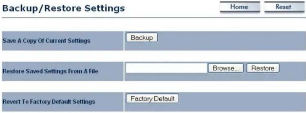
- Save a copy of the current settings: Click on the Backup button to save the current configuration.
- Restore saved settings from a file: Once a file has been backed up, you may restore it by clicking on the Browse button to select the file, and then the Restore button.
- Revert to factory default settings: Click on the Factory Default Settings button to reset the device to the default settings. Please wait while the device restart and then access the device using the default IP address: 192.168.1.1
System Rebooting...
Rebooting, Please wait...
Click here when AP is ready
5.5.10 Firmware Upgrade
- Click on the Upgrade Firmware link under the Management menu. This page is used to upgrade the firmware on the device. Make sure that downloaded the appropriate firmware from your vendor.

- Click on the Browse button and then select the appropriate firmware and then click on the Upgrade button.
Note: The upgrade process may take about 1 minute to complete. Do not power off the device during this process as it may crash the device and make it unusable. The device will restart automatically once the upgrade is complete.
5.5.11 Time Settings
- Click on the Time Settings link under the Management menu. This page allows you to configure the time on the device. You may do this manually or by connecting to a NTP server.

■ Manually Set Date and Time: Specify the date and time
- Automatically Get Date and Time: Select the time zone from the drop down list and then specify the IP address of the NTP server.
- Click on the Apply button to save the changes.
5.5.12 Log
- Click on the Log link under the Management menu. The Log page displays a list of events that are triggered on the Ethernet and Wireless interface. This log can be referred when an unknown error occurs on the system or when a report needs to be sent to the technical support department for debugging purposes.

- Syslog: Choose to enable or disable the system log.
- Log Server IP Address: Specify the IP address of the server that will receive the system log.
- Local Log: Choose to enable or disable the local log.
- Click on the Apply button to save the changes.
Appendix A – Specifications
| Hardware Specification | |
| MCU/RF Atheros AR2315 Single chip | |
| Memory | 32MB SDRAM |
| Flash | 8MB |
| Physical Interface One 10/100 Fast Ethernet RJ-45One Reset ButtonOne SMA ConnectorOne switch (external and internal antenna switching) | |
| LED indicators Power/ Status | LAN (10/100Mbps)WLAN (Wireless is up)3 x Link Quality (Client Bridge mode)➢ Green: Good Quality➢ Yellow: Marginally Acceptable Quality➢ Red: Bad Quality |
| Power Requirements | Active Ethernet (Power over Ethernet) Proprietary PoE designPower Adapter 24 V/0.6A DC |
| Regulation Certifications FCC | Part 15C/15B, EN 300 328/EN 301 489-1/-17 |
| RF Specification | ||||
| Frequency Band 802.11b/g | 2.412~2.472GHz | |||
| Modulation Technology OFDM = BPSK, QPSK, 16-QAM, 64-QAMDSSS = DBPSK, DQPSK, CCK | ||||
| Operating Channels | 802.11b/g11 for North America, 14 for Japan, 13 for Europe | |||
| Receive Sensitivity(Typical) | 802.11g-92 dBm @ 6Mbps-74 dBm @ 54Mbp | 802.11b-97 dBm @ 1Mbps-89 dBm @ 11Mbps | ||
| Available transmit power(Average power) | ||||
| FCC | ETSI | |||
| Frequency | Power | Frequency | Power | |
| 2.412~2.462GHzIEEE802.11g | 23dBm@6~24Mbps22dBm@36Mbps20dBm@48Mbps192dBm@54Mbps | 2.412~2.472GHzIEEE802.11g | 20dBm@6~24Mbps20dBm@36Mbps20dBm@48Mbps19dBm@54Mbps | |
| 2.412~2.462 | 24dBm@1~11Mbps | 2.412~2.472 | 20dBm@1~11Mbps | |
| GHzIEEE802.11b | GHzIEEE802.11b | |||
| Internal Antenna Embedded 7dBi Panel antenna | ||||
| External Antenna 1* SMA connector + 1*5dBi dipole antenna | ||||
| Software Features | |
| General | |
| Topology | Infrastructure |
| Protocol / Standard IEEE 802.3 (Ethernet)IEEE 802.3u (Fast Ethernet)IEEE 802.11b/g (2.4GHz WLAN) | |
| Operation Mode 802.11 b/g | Access PointClient BridgeClient Router |
| LAN | DHCP ServerDHCP Client |
| VPN VPN – pass through | |
| Wireless Channel Selection (Setting varies by countries)Transmission Rate11 b/g : 54, 48, 36, 24, 18, 12, 11, 9, 6, 5.5, 2, 1 in MbpsLong distance transmission : 1km to 30kmTransmit power tableSignal Strength indication using LEDs | |
| Security WEP Encryption-64/128/152 bitWPA/WPA2 Personal (WPA-PSK using TKIP or AES)WPA/WPA2 Enterprise (WPA-EAP using TKIP)802.1x AuthenticatorHide SSID in beaconsWireless STA (Client) connected list | |
| QoS | WMM |
| Management | |
| Configuration | Web-based configuration (HTTP) |
| Firmware Upgrade - Upgrade firmware via web-browser- Keep latest setting when f/w update | |
| Administrator Setting Administrator password change | |
| Reset Setting | - Reboot (Press 1 second)- Reset to Factory Default (Press 5 seconds) |
| System monitoring | Status, Event Log |
| SNMP | V1, V2c (Phase 2) |
| MIB | MIB I, MIB II (RFC1213) |
| Backup & Restore | Settings through Web |
| Time setting NTP (Auto-setting of time)Time setting manually |
| Environmental and Mechanical | |
| Temperature Range Operating | -20°C~70°CStorage -30°C to 80°C |
| Humidity (non-condensing) 0%~90% typical | |
| Dimensions 192mm (L) x48mm (W) x 36mm (H) | |
| Weight | 280g |
Appendix B – FCC Interference Statement
Federal Communication Commission Interference Statement
This equipment has been tested and found to comply with the limits for a Class B digital device, pursuant to Part 15 of the FCC Rules. These limits are designed to provide reasonable protection against harmful interference in a residential installation. This equipment generates uses and can radiate radio frequency energy and, if not installed and used in accordance with the instructions, may cause harmful interference to radio communications. However, there is no guarantee that interference will not occur in a particular installation. If this equipment does cause harmful interference to radio or television reception, which can be determined by turning the equipment off and on, the user is encouraged to try to correct the interference by one of the following measures:
● Reorient or relocate the receiving antenna.
- Increase the separation between the equipment and receiver.
- Connect the equipment into an outlet on a circuit different from that to which the receiver is connected.
- Consult the dealer or an experienced radio/TV technician for help.
FCC Caution: Any changes or modifications not expressly approved by the party responsible for compliance could void the user's authority to operate this equipment.
This device complies with Part 15 of the FCC Rules. Operation is subject to the following two conditions: (1) This device may not cause harmful interference, and (2) this device must accept any interference received, including interference that may cause undesired operation.
IMPORTANT NOTE:
FCC Radiation Exposure Statement:
This equipment complies with FCC radiation exposure limits set forth for an uncontrolled environment.
This device complies with FCC RF Exposure limits set forth for an uncontrolled environment, under 47 CFR 2.1093 paragraph (d)(2).
This transmitter must not be co-located or operating in conjunction with any other antenna or transmitter.


- ACCESS POINT & CLIENT BRIDGE
- USER'S MANUAL
- TABLE OF CONTENTS
- INTRODUCTION
- UNDERSTANDING THE HARDWARE
- SWITCHING BETWEEN OPERATING MODES
- ACCESS POINT OPERATING MODE
- CLIENT BRIDGE OPERATING MODE
- CLIENT ROUTER OPERATING MODE
- APPENDIX A - SPECIFICATIONS
- APPENDIX B - FCC INTERFERENCE STATEMENT
- REVISION HISTORY
- FEATURES
- WIRELESS
- NETWORKING
- SECURITY
- MANAGEMENT
- PACKAGE CONTENTS
- SAFETY GUIDELINES
- SYSTEM REQUIREMENTS
- APPLICATIONS
- DIFFICULT-TO-WIRE ENVIRONMENTS
- TEMPORARY WORKGROUPS
- THE ABILITY TO ACCESS REAL-TIME INFORMATION
- FREQUENTLY CHANGED ENVIRONMENTS
- SMALL OFFICE AND HOME OFFICE (SOHO) NETWORKS
- WIRELESS EXTENSIONS TO ETHERNET NETWORKS
- WIRED LAN BACKUP
- TRAINING/EDUCATIONAL FACILITIES
- HARDWARE INSTALLATION
- HARDWARE DESCRIPTION
- MOUNTING KITS
- IP ADDRESS CONFIGURATION
- LOGGING IN
- STATUS
- MAIN
- WIRELESS CLIENT LIST
- SYSTEM LOG
- SYSTEM
- SYSTEM PROPERTIES
- IP SETTINGS
- SPANNING TREE SETTINGS
- WIRELESS NETWORK
- WIRELESS SETTING
- WIRELESS SECURITY
- WIRELESS SECURITY - WEP
- WIRELESS SECURITY – WPA-PSK, WPA2-PSK, WPA-MIXED
- WIRELESS SECURITY – WPA, WPA
- WIRELESS MAC FILTER
- WIRELESS ADVANCED SETTINGS
- ADMINISTRATION
- SNMP SETTINGS
- BACKUP/RESTORE SETTINGS, RESET TO FACTORY DEFAULT SETTINGS
- SYSTEM REBOOTING
- REBOOTING, PLEASE WAIT
- FIRMWARE UPGRADE
- TIME SETTINGS
- LOG
- CONNECTION STATUS
- WIRELESS SECURITY – WPA-PSK, WPA2-PSK
- ROUTER
- WAN SETTINGS
- WAN - DHCP
- WAN - STATIC IP
- APPLY CANCEL
- WAN - PPPOE
- VPN PASS THROUGH
- APPENDIX B – FCC INTERFERENCE STATEMENT
- FEDERAL COMMUNICATION COMMISSION INTERFERENCE STATEMENT
- IMPORTANT NOTE
- FCC RADIATION EXPOSURE STATEMENT
Brand : Ansel
Model : 2014
Category : Access Point