850-10960-2DC - Uncategorized IMC Networks - Free user manual and instructions
Find the device manual for free 850-10960-2DC IMC Networks in PDF.


User questions about 850-10960-2DC IMC Networks
0 question about this device. Answer the ones you know or ask your own.
Ask a new question about this device
Download the instructions for your Uncategorized in PDF format for free! Find your manual 850-10960-2DC - IMC Networks and take your electronic device back in hand. On this page are published all the documents necessary for the use of your device. 850-10960-2DC by IMC Networks.
USER MANUAL 850-10960-2DC IMC Networks
natural_image
Abstract red logo design with geometric shapes and radiating lines (no text or symbols)Networks
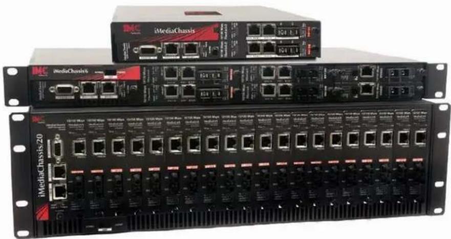
iMediaChassis Series
• iMediaChassis/20
- iMediaChassis/6
- iMediaChassis/3
Operation Manual
natural_image
Three black network equipment units (iMediaChassis, iMediaChassis/20) with Ethernet ports and I/O ports, no visible text or labels on the devices themselves.Class A
This equipment has been tested and found to comply with the limits for a Class A computing device, pursuant to Part 15 of the FCC Rules. These limits are designed to provide reasonable protection against harmful interference when the equipment is operated in a commercial environment. This equipment generates, uses and can radiate radio frequency energy and, if not installed and used in accordance with the instruction manual, may cause harmful interference to radio communications. Operation of this equipment in a residential area is likely to cause harmful interference in which the user will be required to correct the interference at his own expense.
Any changes or modifications not expressly approved by the manufacturer could void the user's authority to operate the equipment.
The use of non-shielded I/O cables may not guarantee compliance with FCC RFI limits. This digital apparatus does not exceed the Class A limits for radio noise emission from digital apparatus set out in the Radio Interference Regulation of the Canadian Department of Communications.
This equipment has been tested and found to comply with the limits for a Class B computing device, pursuant to Part 15 of the FCC Rules. These limits are designed to provide reasonable protection against harmful interference when the equipment is operated in a commercial environment. This equipment generates, uses and can radiate radio frequency energy and, if not installed and used in accordance with the instruction manual, may cause harmful interference to radio communications. Operation of this equipment in a residential area is likely to cause harmful interference in which the user will be required to correct the interference at his own expense.
Any changes or modifications not expressly approved by the manufacturer could void the user's authority to operate the equipment.
The use of non-shielded I/O cables may not guarantee compliance with FCC RFI limits. This digital apparatus does not exceed the Class B limits for radio noise emission from digital apparatus set out in the Radio Interference Regulation of the Canadian Department of Communications.
IMC Networks warrants to the original end-user purchaser that this product, EXCLUSIVE OF SOFTWARE, shall be free from defects in materials and workmanship under normal and proper use in accordance with IMC Networks' instructions and directions for a period of six (6) years after the original date of purchase. This warranty is subject to the limitations set forth below.
At its option, IMC Networks will repair or replace at no charge the product which proves to be defective within such warranty period. This limited warranty shall not apply if the IMC Networks product has been damaged by unreasonable use, accident, negligence, service or modification by anyone other than an authorized IMC Networks Service Technician or by any other causes unrelated to defective materials or workmanship. Any replaced or repaired products or parts carry a ninety (90) day warranty or the remainder of the initial warranty period, whichever is longer.
To receive in-warranty service, the defective product must be received at IMC Networks no later than the end of the warranty period. The product must be accompanied by proof of purchase, satisfactory to IMC Networks, denoting product serial number and purchase date, a written description of the defect and a Return Merchandise Authorization (RMA) number issued by IMC Networks. No products will be accepted by IMC Networks which do not have an RMA number. For an RMA number, contact IMC Networks at PHONE: (800) 624-1070 (in the U.S and Canada) or (949) 465-3000 or FAX: (949) 465-3020. The end-user shall return the defective product to IMC Networks, freight, customs and handling charges prepaid. End-user agrees to accept all liability for loss of or damages to the returned product during shipment. IMC Networks shall repair or replace the returned product, at its option, and return the repaired or new product to the end-user, freight prepaid, via method to be determined by IMC Networks. IMC Networks shall not be liable for any costs of procurement of substitute goods, loss of profits, or any incidental, consequential, and/or special damages of any kind resulting from a breach of any applicable express or implied warranty, breach of any obligation arising from breach of warranty, or otherwise with respect to the manufacture and sale of any IMC Networks product, whether or not IMC Networks has been advised of the possibility of such loss or damage.
EXCEPT FOR THE EXPRESS WARRANTY SET FORTH ABOVE, IMC NETWORKS MAKES NO OTHER WARRANTIES, WHETHER EXPRESS OR IMPLIED, WITH RESPECT TO THIS IMC NETWORKS PRODUCT, INCLUDING WITHOUT LIMITATION ANY SOFTWARE ASSOCIATED OR INCLUDED. IMC NETWORKS SHALL DISREGARD AND NOT BE BOUND BY ANY REPRESENTATIONS OR WARRANTIES MADE BY ANY OTHER PERSON, INCLUDING EMPLOYEES, DISTRIBUTORS, RESELLERS OR DEALERS OF IMC NETWORKS, WHICH ARE
INCONSISTENT WITH THE WARRANTY SET FORTH ABOVE. ALL IMPLIED WARRANTIES INCLUDING THOSE OF MERCHANTABILITY AND FITNESS FOR A PARTICULAR PURPOSE ARE HEREBY LIMITED TO THE DURATION OF THE EXPRESS WARRANTY STATED ABOVE.
Every reasonable effort has been made to ensure that IMC Networks product manuals and promotional materials accurately describe IMC Networks product specifications and capabilities at the time of publication. However, because of ongoing improvements and updating of IMC Networks products, IMC Networks cannot guarantee the accuracy of printed materials after the date of publication and disclaims liability for changes, errors or omissions.
Table of Contents
FCC Radio Frequency Interference Statement ....ii
Class A....ii
Class B ...... ii
Warranty....iii
About the iMediaChassis/20 ....1
iMediaChassis/20 Features ....1
Alarm Reset, Last Gasp and Temperature Gauge ....1
Alarm Reset Button 2
Last Gasp Alarm ....2
Temperature Gauge 2
SNMP Write Lock 2
SNMP Management Module LEDs ....3
Installing the iMediaChassis/20....3
Wiring Instruction Guidelines for DC Module in 2DC and ACDC......4
DC Power Supply Module Wiring Instructions....4
Installing SNMP Management and Application Modules....5
Replacing Power Supply Modules 6
User-Replaceable Power Supply Modules 6
Dual DC, Part Number 850-10954-2DC....6
Dual AC, Part Number 850-10956-2AC....7
Dual AC, Part Number 850-10960-2AC....7
Dual DC, Part Number 850-10960-2DC....8
ACDC, Part Number 850-10960-ACDC....8
iMediaChassis/20 Specifications 9
About the iMediaChassis/6 ....10
iMediaChassis/6 Features 10
Alarm Reset, Last Gasp, and Temperature Gauge ....10
Alarm Reset Button 10
Last Gasp Alarm ....11
Temperature Gauge ....11
SNMP Write Lock 11
SNMP Management Module LEDs 12
Installing the iMediaChassis 6....12
DC Power Wiring, Replacing Power Supply Modules and Fans 14
DC Power Supply Wiring Instructions....14
User-Replaceable Power Supply Modules 14
Fans....14
Installing Management and Application Modules....15
Installing Applications Modules ....15
iMediaChassis/6 Specifications ....16
About the iMediaChassis/3 ....17
iMediaChassis/3 Features ....17
Alarm Reset, Last Gasp, and Temperature Gauge ....17
Alarm Reset Button 17
Last Gasp Alarm 17
Temperature Gauge ....18
Installing the iMediaChassis/3....18
DC Power Wiring, Replacing Power Supply Modules and Fans 19
DC Power Supply Module Wiring Instructions....19
Power Supply Modules 20
Fans....20
Installing Management and Application Modules....20
Installing Applications Modules ......20
SNMP Write Lock 21
SNMP Management Module LEDs 21
iMediaChassis/3 Specifications 23
Hardware Feature Matrix 23
IMC Networks Technical Support....24
Electrostatic Discharge Precautions....25
Safety Certifications....26
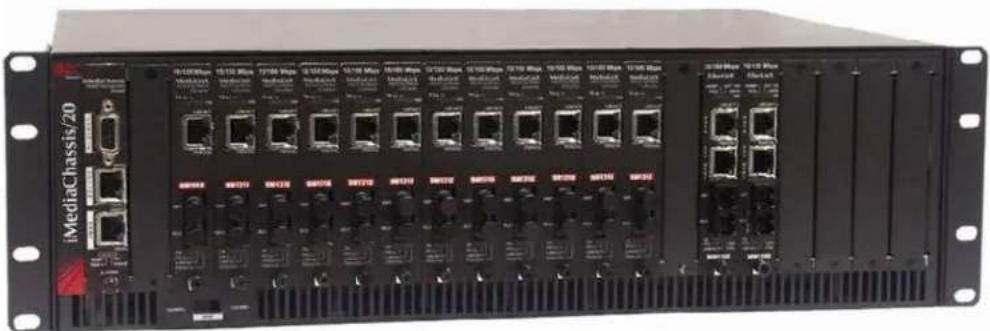
The iMediaChassis series is a modular chassis platform designed for use with IMC Networks' Simple Network Management Protocol (SNMP) manageable series of modules. The iMediaChassis/20 is a 3U high, Rackmountable chassis that features 20 slots for installing application series modules plus an additional slot for installing an SNMP Management Module. Power supply modules are user-replaceable and hot-swappable.
iMediaChassis/20 Features
The iMediaChassis/20 line offers models available in dual AC, dual DC and ACDC versions. It offers features such as end-user replaceable power supply modules, temperature monitoring, Last Gasp and an Alarm Reset Button.
natural_image
Front view of an iMediaChassis/20 network switch unit with multiple Ethernet ports and ventilation grilles (no visible text or labels beyond branding)Alarm Reset, Last Gasp and Temperature Gauge
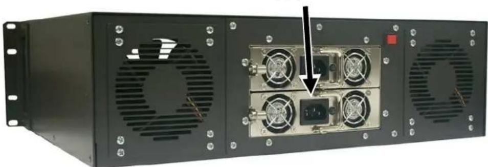
The iMediaChassis series supports power supply modules, so that worn parts can be replaced without having to send an entire unit in for repair.
User-Replaceable Power Supply Modules
natural_image
Front view of a black industrial server rack with four fans and a central control panel (no visible text or labels)Alarm Reset Button
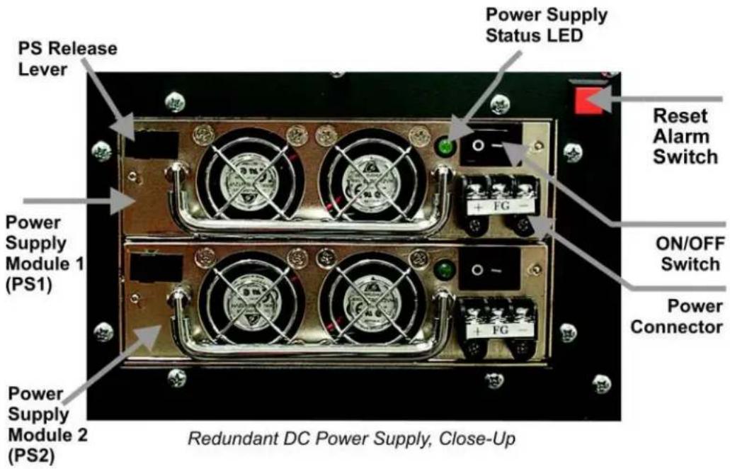
When one power supply module malfunctions, an audible alarm sounds indicating the loss of the power module. The alarm can be silenced by pressing the Alarm Reset Button, located next to the power connector on the power supply module. If this occurs, remove and replace the power supply module immediately. (LEDs on the Management Module and the power supply module itself also indicate power supply module failures.)
Last Gasp Alarm
The iMediaChassis series includes the Last Gasp trap feature, "Remote Chassis Down", which sends a Trap when the following occurs:
- Both power supply modules malfunction
- Both power supply modules are powered down
- When the AC line fails
Temperature Gauge
The iMediaChassis/20 includes a temperature monitoring gauge with a heat sensor on the backplane of the chassis. Users define a threshold for chassis temperature via SNMP. If the chassis' temperature rises above the specified level, the SNMP agent sends a trap (configured in iView ^4 ) to the administrator. There is also an LED indicator on the SNMP Management Module for chassis temperature.
SNMP Write Lock
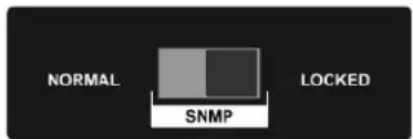
There is an SNMP Write Lock switch located below slot #3 on the front of the iMediaChassis/20. The SNMP Write Lock switch prevents a new management board from re-configuring the application module settings
(e.g., the status of features such as LinkLoss, FiberAlert, Force mode, etc.) made via SNMP on any previous Management Modules.
text_image
NORMAL SNMP LOCKEDNOTE
Leave this switch in the NORMAL position during day-to-day operation; the LOCKED position should only be used when changing the SNMP management board.
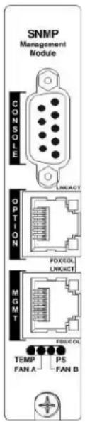
The SNMP Management Module can be removed and replaced as necessary. Refer to the SNMP Management Module manual for complete instructions about configuration and operation. If an SNMP Management Module is installed, refer to the LED panel below for indicators of Link, Temperature, Power supply modules and other functions.
SNMP Management Module LEDs
The SNMP Management Module features several LEDs. The LED functions are:
LNK/ACT Glows green when a link is established on port. Blinks green when data activity occurs.
FDX/COL Glows yellow when port is in Full-Duplex mode. Blinks yellow when port is operating in Half-Duplex mode and collisions occur.
TEMP Glows yellow when temperature of unit surpasses a user-defined level.
PS Glows yellow when one module malfunctions.
FAN A / FAN B Glows yellow when a fan malfunctions.
text_image
SNMP Management Module CONSOLE OPTION MGMT TEMP FAN A PS FAN B LINK/ACT PDX/OL LINK/ACT FOLD/OLInstalling the iMediaChassis/20
Install the chassis first before installing any modules into an iMediaChassis. When installing the chassis, be sure to observe the following precautions to prevent electrical or mechanical damage:
-
Protect the chassis from exposure to sunlight and electrical or magnetic fields.
-
Ensure that the equipment rack remains stable, even with the addition of the chassis and its associated cabling.
To install 20 -slot Rackmount chassis:
-
Have four #10 screws and four clip nuts available (hardware may vary depending on rack type). The rest of the hardware is supplied with the unit.
-
Locate a suitable location in the rack for installation and secure the clip-nuts onto the mounting rails. Use screws to attach the chassis to the rack.
-
Plug the chassis into a reliable, filtered power source.
-
Elevated Operating Ambient - If installed in a closed or multi-unit rack assembly, the operating ambient temperature of the rack environment may be greater than room ambient. Therefore, consideration should be given to installing the equipment in an environment compatible with the maximum ambient temperature (Tma) specified by the IMC Networks.
-
Reduced Air Flow - Installation of the equipment in a rack should be such that the amount of air flow required for safe operation of the equipment is not compromised.
- Mechanical Loading - Mounting of the equipment in the rack should be such that a hazardous condition is not achieved due to uneven mechanical loading.
- Circuit Overloading - Consideration should be given to the connection of the equipment to the supply circuit and the effect that overloading of the circuits might have on over current protection and supply wiring.
- Reliable Grounding - Reliable grounding of Rackmounted equipment should be maintained. Particular attention should be given to supply connections other than direct connections to the branch circuit (e.g., use of power strips).
- All AC and DC versions are intended for use in a Restricted Access Location (RAL).
Wiring Instruction Guidelines for DC Module in 2DC and ACDC
- Connection of a suitable grounding conductor to the grounding terminal at each power supply module (a minimum 14AWG copper conductor should be suitable based on a 15A circuit breaker requirement).
- Connection of suitable supply wiring to the plus and minus terminals at each power supply module (a minimum 14AWG copper conductors is considered suitable based on the 11A input maximum). The input terminal block at the power supply module is suitable for 22-14 AWG copper wire.
- A suitable listed circuit breaker shall be provided in the building installation as the unit's disconnect device. The branch circuit rating (i.e. minimum 15A listed circuit breaker, etc.).
DC Power Supply Module Wiring Instructions
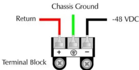
The following diagram shows the wiring configuration for a -48 VDC power supply module for the iMediaChassis/20-2DC and iMediaChassis/20-ACDC.
text_image
Chassis Ground Return -48 VDC Terminal BlockNOTE
The chassis is protected against incorrect wiring configurations. When wired incorrectly, the chassis will not function, but no damage will occur.
Installing SNMP Management and Application Modules
To install a module:
- Remove the blank bracket (if present) covering the slot where the module will be installed. IMC Networks recommends installing blank brackets in unused module slots.
- Slide the module into the chassis using the card guides.
- Secure the module to the chassis by tightening the captive screw. (Refer to the documentation shipped with the module for configuration information.)
- When installing modules observe ESD precautions, refer to the Electrostatic Discharge Precautions section.
In order to manage an iMediaChassis series, the SNMP Management Module needs to be installed in the appropriate slot of the chassis.
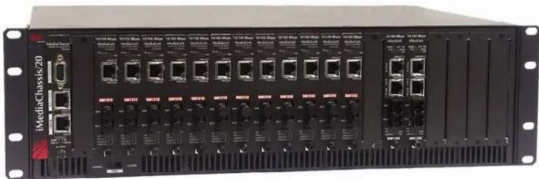
- Install the iMediaChassis/20 SNMP Management Module into the first slot of the chassis.
| NOTE |
| This slot is ONLY for the Management Module; do not install Application Modules such as media conversion and mode conversion modules in this slot. |
natural_image
Front view of an iMediaChassis/20 network switch unit with multiple Ethernet ports and drive bays (no visible text or labels beyond branding)Replacing Power Supply Modules
User-Replaceable Power Supply Modules
While power supply modules are redundant *, failed power supply modules should promptly be replaced to maintain network integrity and prevent data loss.
To replace a power supply module:
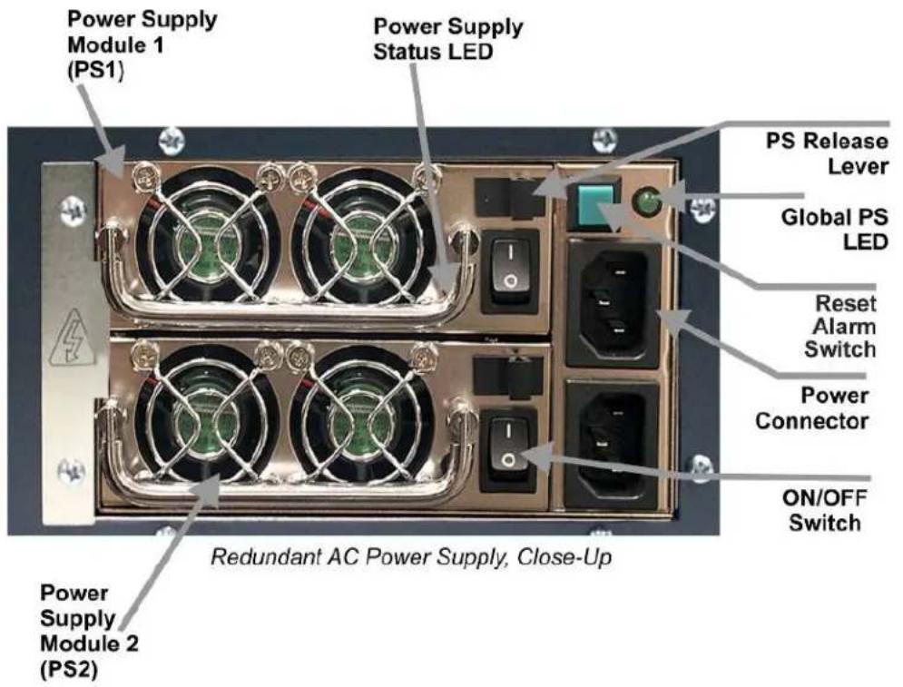
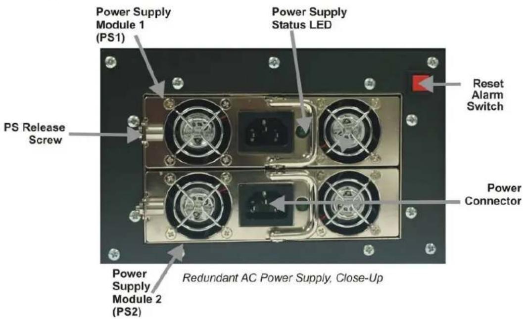
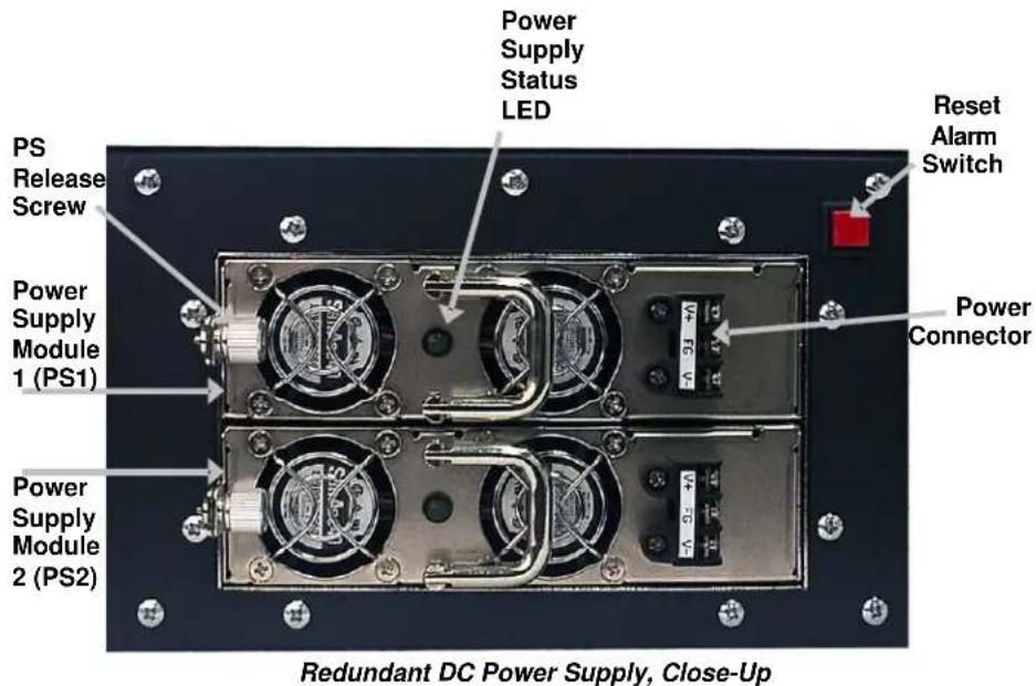
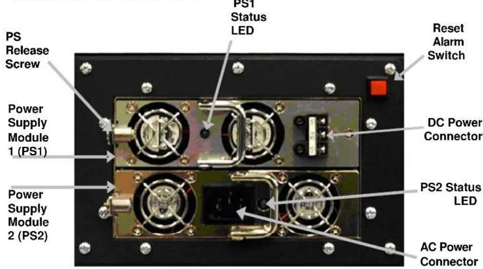
- Disconnect the power source from the power supply module.
- Remove the screws of the retainer plate (on some AC modules).
- Move the Power Supply Release switch toward the right or unscrew captive release screw.
- Before grasping the power supply module by the silver handle, press the release screw and then slide out of the chassis (Power supply modules are hot-swappable).
- Install new power supply module. If module is equipped with an ON/OFF switch install the module with the switch in the OFF position.
Dual DC, Part Number 850-10954-2DC
text_image
Power Supply Status LED PS Release Lever Reset Alarm Switch Power Supply Module 1 (PS1) ON/OFF Switch Power Connector Power Supply Module 2 (PS2) Redundant DC Power Supply, Close-UpDual AC, Part Number 850-10956-2AC
text_image
Power Supply Module 1 (PS1) Power Supply Status LED PS Release Lever Global PS LED Reset Alarm Switch Power Connector ON/OFF Switch Power Supply Module 2 (PS2) Redundant AC Power Supply, Close-UpNOTE
Do not mix AC and DC power supply modules.
Dual AC, Part Number 850-10960-2AC
text_image
Power Supply Module 1 (PS1) Power Supply Status LED Reset Alarm Switch PS Release Screw Power Connector Power Supply Module 2 (PS2) Redundant AC Power Supply, Close-UpDual DC, Part Number 850-10960-2DC
text_image
Power Supply Status LED PS Release Screw Power Supply Module 1 (PS1) Power Supply Module 2 (PS2) Reset Alarm Switch Power Connector Redundant DC Power Supply, Close-Up*Does not support redundancy.
ACDC, Part Number 850-10960-ACDC
text_image
PS Release Screw Power Supply Module 1 (PS1) Power Supply Module 2 (PS2) PS1 Status LED Reset Alarm Switch DC Power Connector PS2 Status LED AC Power ConnectorRedundant ACDC Power Supply, Close-Up
NOTE
For 850-10960-XX iMediaChassis/20, all models in that model number series can support Dual AC, Dual DC or ACDC. The power supply modules for that model number series are interchangeable.
iMediaChassis/20 Specifications
Input Specifications
| Dual AC | 100 to 240V AC, 50/60Hz, 3.5/1.5A |
| Dual DC -48V DC, 5A | |
| ACDC 100 to 240V AC, 50/60HZ, 2A-48V DC, 4.4A | |
Operating Temperature
0^ C to 50^ C (32°F to 122°F)
Storage Temperature
| Dual AC & ACDC -20°C to 80°C (-4°F to 176°F) |
| Dual DC -20°C to 60°C (-4°F to 140°F) |
Humidity
20 to 90% (non-condensing at 40°C)
Shipping Weight
25 lbs (11.3 kg)
Dimensions
5.2" x 19.0" x 13.8" (13.21cm x 48.26cm x 35.05cm)
About the iMediaChassis/6
The iMediaChassis series is a modular chassis platform designed for use with IMC Networks' Simple Network Management Protocol (SNMP) manageable series of modules. The iMediaChassis/6 is 1U high, Rackmountable and supports optional redundant power supply modules, as well as an SNMP Management Module.
iMediaChassis/6 Features
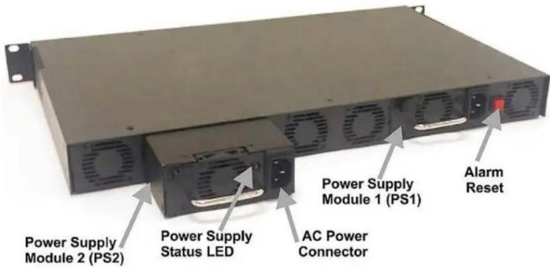
The iMediaChassis/6 series offers a line of models including single AC, single DC, dual AC and dual DC. It offers features such as end-user replaceable power supply modules, temperature monitoring, Last Gasp and an Alarm Reset Button.
text_image
Power Supply Module 2 (PS2) Power Supply Status LED AC Power Connector Power Supply Module 1 (PS1) Alarm ResetAlarm Reset, Last Gasp, and Temperature Gauge
The iMediaChassis series supports modular power supply modules, so that worn parts can be replaced without having to send an entire unit in for repair. Keeping fans functional ensures that the modules will operate within their temperature specifications.
Alarm Reset Button
When one power supply module malfunctions, an audible alarm sounds indicating the loss of the power supply module. The alarm can be silenced by pressing the Alarm Reset Button, located next to the power connector on the power supply module. If this occurs, remove and replace the power supply module immediately. (LEDs on the Management Module and the power supply itself also indicate power supply failures.) After stopping the alarm, remove the power supply and replace the power supply module.
Last Gasp Alarm
The iMediaChassis series includes the Last Gasp trap feature, "Remote Chassis Down", which sends a Trap when the following occurs:
- Both power supply modules malfunction
- Both power supply modules are powered down
- When the AC line fails
Temperature Gauge
The iMediaChassis/6 includes a temperature monitoring gauge with a heat sensor on the backplane of the chassis. Users define a threshold for chassis temperature via SNMP. If the chassis' temperature rises above the specified level, the SNMP agent sends a trap (configured in iView ^2 ) to the administrator. There is also an LED indicator on the SNMP Management Module for chassis temperature.
SNMP Write Lock
There is an SNMP Write Lock switch located above the SNMP module slot on the front of the iMediaChassis/6. The SNMP Write Lock switch prevents a new
management board from re-configuring the
application module settings (e.g., the status of features such as LinkLoss, FiberAlert, Force mode, etc.) made via SNMP on any previous Management Modules.

text_image
NORMAL SNMP LOCKEDNOTE
Leave this switch in the NORMAL position during day-to-day operation; the LOCKED position should only be used when changing the SNMP management board.
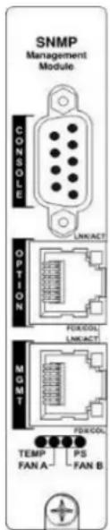
The SNMP Management Module can be removed and replaced as necessary. Refer to the SNMP Management Module manual for complete instructions about configuration and operation. If an SNMP Management Module is installed, refer to the LED panel below for indicators of Link, Temperature, Power Supply modules and other functions.
SNMP Management Module LEDs
The SNMP Management Module features several LEDs. The LED functions are:
LNK/ACT Glows green when a link is established on port. Blinks green when data activity occurs.
FDX/COL Glows yellow when port is in Full-Duplex mode. Blinks yellow when port is operating in Half-Duplex mode and collisions occur.
TEMP Glows yellow when temperature of unit surpasses a user-defined level.
PS Glows yellow when one power supply module malfunctions.
FAN A / FAN B Glows yellow when a fan malfunctions.
text_image
SNMP Management Module CONSOLE LINKACT OPTION MGMT TEMP FAN A PS FAN BInstalling the iMediaChassis 6
Install the chassis first before installing any modules into an iMediaChassis.
When installing the chassis, be sure to observe the following precautions to prevent electrical or mechanical damage:
-
Protect the chassis from exposure to sunlight and electrical or magnetic fields.
-
Ensure that the equipment rack remains stable, even with the addition of the chassis and its associated cabling.
To install a 6-slot Rackmount chassis:
-
Have four #10 screws and four clip nuts available (hardware may vary depending on rack type). The rest of the hardware is supplied with the unit.
-
Locate a suitable location in the rack for installation and secure the clip-nuts onto the mounting rails. Use screws to attach the chassis to the rack.
-
Plug the chassis into a reliable, filtered power source.
-
Elevated Operating Ambient - If installed in a closed or multi-unit rack assembly, the operating ambient temperature of the rack environment may be greater than room ambient. Therefore, consideration should be given to installing the equipment in an environment compatible with the maximum ambient temperature (Tma) specified by the IMC Networks.
-
Reduced Air Flow - Installation of the equipment in a rack should be such that the amount of air flow required for safe operation of the equipment is not compromised.
- Mechanical Loading - Mounting of the equipment in the rack should be such that a hazardous condition is not achieved due to uneven mechanical loading.
- Circuit Overloading - Consideration should be given to the connection of the equipment to the supply circuit and the effect that overloading of the circuits might have on over current protection and supply wiring.
- Reliable Grounding - Reliable grounding of Rackmounted equipment should be maintained. Particular attention should be given to supply connections other than direct connections to the branch circuit (e.g., use of power strips).
- All AC and DC versions are intended for use in a Restricted Access Location (RAL).
DC Power Wiring, Replacing Power Supply Modules and Fans
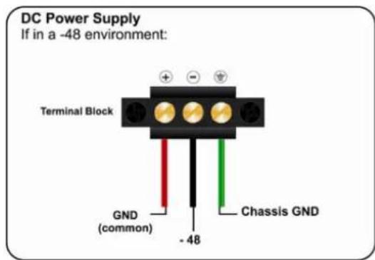
DC Power Supply Wiring Instructions
The following diagram shows the wiring configurations for -48 VDC power supply modules for the iMediaChassis/6.
text_image
DC Power Supply If in a -48 environment: Terminal Block GND (common) - 48 Chassis GND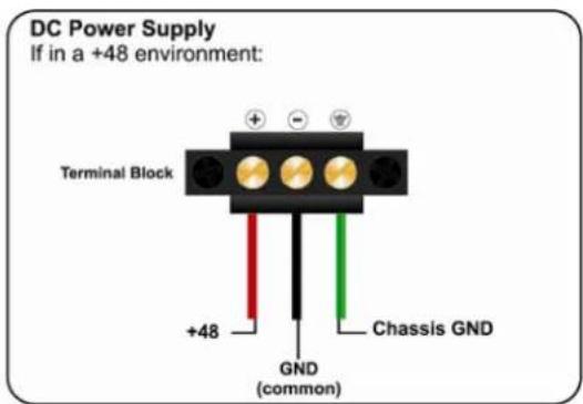
text_image
DC Power Supply If in a +48 environment: Terminal Block +48 GND (common) Chassis GNDUser-Replaceable Power Supply Modules
The iMediaChassis/6 ships from IMC Networks with one or two power supply modules installed depending on the model. Chassis ordered with one power supply come with a filler tray installed in the second slot.
To install a second power supply:
- Remove the filler tray.
- Slide the power supply module into the chassis and click into place.
- Attach power cord.
To remove a power supply module:
- Disconnect the power source from the power supply.
- Move the Power Supply Release switch toward the right and hold while grasping the power supply module by the silver handle.
- Slide out of the chassis. (Power supply modules are hot-swappable.)
- Install new power supply module.
Fans
Users can define a threshold for fan operation via SNMP (when installed in a managed environment). If a fan's speed falls below the specified level, SNMP sends a trap (configured in iView ^2 ) to the administrator. There are also two LED indicators on the SNMP Management Module for fan failure.
The red Alarm Reset Button also functions as a Fan Test button. To verify fan functionality, hold the button down for several seconds, the fans should engage. The fans will turn off when the button is released.
SNMP Management Modules include two twisted pair ports, one for management and one reserved for future use. The Management Module also features a DB-9 serial port, and supports SNMP V1/V2c.
Installing Management and Application Modules
Installing Applications Modules
To install a module:
- Remove the blank bracket (if present) covering the slot where the module will be installed. IMC Networks recommends installing blank brackets in unused module slots.
- Slide the module into the chassis using the card guides.
- Secure the module to the chassis by tightening the captive screw. (Refer to the documentation shipped with the module for configuration information.)
- When installing modules observe ESD precautions, refer to the Electrostatic Discharge Precautions section.
In order to manage an iMediaChassis series, the SNMP Management Module needs to be installed in the appropriate slot of the chassis.
• Install the iMediaChassis/6 slot into the first slot on the far left of the chassis.
| NOTE |
| This slot is ONLY for the Management Module; do not install Application Modules such as media conversion and mode conversion modules into this slot. |

text_image
iMediaChassis/5 1000 MHz Ethernet 8 1000 MHz Ethernet 8 1000 MHz Ethernet 8 1000 MHz Ethernet 8 1000 MHz Ethernet 8 1000 MHz Ethernet 8 1000 MHz Ethernet 8 1000 MHz Ethernet 8 1000 MHz Ethernet 8 1000 MHz Ethernet 8 1000 MHz Ethernet 6 1000 MHz Ethernet 6 1000 MHz Ethernet 6 1000 MHz Ethernet 6 1000 MHz Ethernet 6 1000 MHz Ethernet 6 1000 MHz Ethernet 6 1000 MHz Ethernet 6 1000 MHz Ethernet 6 1000 MHz Ethernet 6 1000 MHziMediaChassis/6 Specifications
Input Specifications
| AC 100 to 240V AC, 50/60Hz, 1A | |
| DC | -48V DC, 2A |
Operating Temperature:
| AC | -25^ C to 50^ C ( -130^ F - 122^ F) |
| DC | -40^ C to 100^ C ( -40^ F - 212^ F) |
Storage Temperature:
| AC -40°C to 85°C (-40°F - 185°F) |
| DC -55°C to 125°C (-67°F - 257°F) |
Humidity
5 - 95% (non-condensing); 0-10,000 ft. altitude
Shipping Weight
13 lbs (5.90 kg)
Dimensions
1.75" x 17.35" x 10.65" (4.45cm x 44.07cm x 27.05cm)
About the iMediaChassis/3
The iMediaChassis series is a modular chassis platform designed for use with IMC Networks' Simple Network Management Protocol (SNMP) manageable series of modules. The iMediaChassis/3 is a 1U high, Rackmountable, capable of offering redundant power supply modules, and supports an SNMP Management Module.
iMediaChassis/3 Features
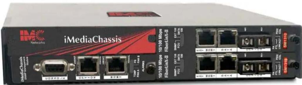
The iMediaChassis/3 series offers a line of models including single AC, single DC, dual AC, dual DC and ACDC version. All contain internal fixed power supply modules that are not end-user replaceable. It offers features such as redundant power supply modules, temperature monitoring, Last Gasp and an Alarm Reset Button.
text_image
iMediaChassis Networks iMediaChassis 10/100 Mbps 70/100 Mbps FiberLinX-II FibetinX-II 80MP 65T 100 FCU DATA 100 30S 30S FCU DATA 100 40S 40S FCU DATA 100 40S 40S FCU DATA 100 40S 40S FCU DATA 100 40S 40S FCU DATA 100 40S 40S FCU DATA 100 40S 40S FCU DATA 100 40S 40S FTL LIN/ATY COI 40S COI FTL LIN/ATY COI 40S COI FTL LIN/ATY COI 40S COI FTL LIN/ATY COI 40S COI FTL LIN/ATY COI 40S COI FTL LIN/ATY COI 40S COI FTL LIN/ATY COI 40S COI FTL LIN/ATY COIAlarm Reset, Last Gasp, and Temperature Gauge
The iMediaChassis/3 ships with one or two AC or DC power supply modules, depending on the model. Fans are included in all models.
Alarm Reset Button
When one power supply module malfunctions, an audible alarm sounds indicating the loss of the power supply. The alarm can be silenced by pressing the Alarm Reset Button, located next to the power connector on the power supply module. If this occurs the unit needs to be returned to IMC for repair.
Last Gasp Alarm
The iMediaChassis series includes the Last Gasp trap feature, "Remote Chassis Down", which sends a Trap when the following occurs:
- Both power supply modules malfunction
- Both power supply modules are powered down
- When the AC line fails
Temperature Gauge
The iMediaChassis/3 includes a temperature monitoring gauge with a heat sensor on the backplane of the chassis. Users define a threshold for chassis temperature via SNMP. If the chassis' temperature rises above the specified level, the SNMP agent sends a trap (configured in iView ^2 ) to the administrator. There is also an LED indicator on the SNMP Management Module for chassis temperature.
Installing the iMediaChassis/3
Install the chassis first before installing any modules into an iMediaChassis.
When installing the chassis, be sure to observe the following precautions to prevent electrical or mechanical damage:
- Stay within the chassis' power rating to prevent overload of supply circuits or damage to any overcurrent protection and supply wiring.
- Maintain reliable ground, especially when connecting to a power strip instead of directly to a branch circuit.
- Protect the chassis from exposure to sunlight and electrical or magnetic fields.
- Ensure that the equipment rack remains stable, even with the addition of the chassis and its associated cabling.
Use the iMcV-MediaChassis/3 as a table-top chassis, mount in a Rackmount shelf or mount it to a wall surface.
To install the 3-slot Rackmount in the chassis:
- Install the iMcV-MediaChassis/3 by placing it on a flat surface.
- Make sure to leave adequate space on the sides of the unit to accommodate cooling.
- If mounting on a Rackmount shelf, align holes of the chassis to the shelf and secure with screws.
The Rackmount shelf is sold separately. To purchase the Rackmount shelf (part number (895-39949); visit the IMC Networks' Product Accessories page:
https://www.imcnetworks.com/Products/acc.cfm
Rackmounting requires a Rackmount shelf for mounting up to two units side by side.
-
Attach the cables between the chassis and the device that will be interconnected, and then plug the unit into a reliable, filtered power source.
-
If mounting the chassis on a wall, place two #10 panhead screws (not supplied) on the wall according to the distance of the holes on the chassis, and then hang the unit on the screws.
- All versions are intended for use in a Restricted Access Location (RAL).
- A readily accessible disconnect device shall be incorporated in the building installation wiring.
- A suitable listed circuit breaker shall be provided in the building installation as the unit's disconnect device. The branch circuit rating (i.e. minimum 15A listed circuit breaker, etc.).
DC Power Wiring, Replacing Power Supply Modules and Fans
DC Power Supply Module Wiring Instructions
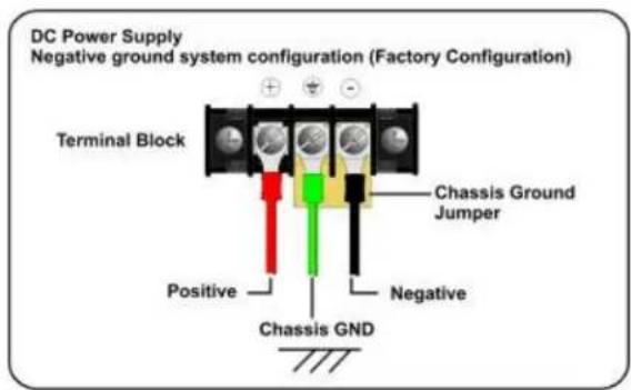
The following image shows the wiring configuration for a 48 VDC power supply in a negative ground system application. For positive ground system applications remove the chassis ground shorting jumper and connect it between the positive terminal and the chassis ground terminal. Alternatively, the chassis grounding jumper can be eliminated and the chassis ground connected at the power source. The ground terminal and the negative terminal are not connected inside the iMediaChassis/3.
DC Power Supply
Negative ground system configuration (default position)
text_image
DC Power Supply Negative ground system configuration (Factory Configuration) Terminal Block Chassis Ground Jumper Positive Negative Chassis GNDNOTE
Incorrect wiring will result in chassis malfunction.
The iMediaChassis/3 is compliant with Isolated Grounding Plane practices. The POSITIVE and NEGATIVE terminals are isolated from chassis ground and must have a ground reference at the power-sourcing equipment.
Power Supply Modules
Power supply modules in all models of the iMediaChassis/3 are fixed, and not end-user replaceable.
Fans
The iMediaChassis/3 includes temperature-triggered fans. When the temperature of the chassis reaches 40^ C, the two fans activate to cool the chassis. The fans' operation can be tested by holding the Alarm Reset Button down for 4 to 5 seconds. The fans will activate and then they will turn off when the button is released. If the fans do not activate, contact IMC Networks. Fans are not end-user replaceable.
The red Alarm Reset Button also functions as a Fan Test button. To verify fan functionality, hold the button down for several seconds, the fans should engage. The fans will turn off when the button is released.
Installing Management and Application Modules
SNMP Management Modules include two twisted pair ports, one for management and one reserved for future use. The Management Module also features a DB-9 serial port, and supports SNMP V1/V2c.
Installing Applications Modules
To install a module:
- Remove the blank bracket (if present) covering the slot where the module will be installed. IMC Networks recommends installing blank brackets in unused module slots.
- Slide the module into the chassis using the card guides.
- Secure the module to the chassis by tightening the captive screw. (Refer to the documentation shipped with the module for configuration information.)
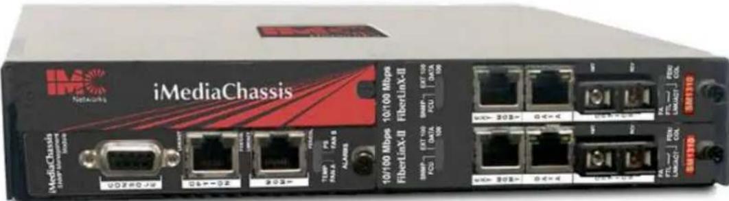
In order to manage an iMediaChassis series, the SNMP Management Module needs to be installed in the appropriate slot of the chassis.
- Install the iMediaChassis/3 slot SNMP Management Module into the bottom left slot.
NOTE
This slot is ONLY for the Management Module; do not install Application Modules such as media conversion and mode conversion modules in this slot.
text_image
iMediaChassis Networks iMediaChassis 10/100 Mbps 10x100 Mbps FiberLink-II FiberLink-II 10x100 Mbps 10x100 Mbps FiberLink-II FiberLink-II 10x100 Mbps 10x100 Mbps FiberLink-II FiberLink-II 10x100 Mbps 10x100 Mbps FiberLink-II FiberLink-II 10x100 Mbps 10x100 Mbps FiberLink-II FiberLink-II 10x100Mbps FiberLink-II FiberLink-II FiberLink-II 10x100Mbps FiberLink-II FiberLink-II FiberLink-II 10x100Mbps FiberLink-II FiberLink-II FiberLink-II 10x100Mbps FiberLink-II FiberLink-II FiberLink-II 10x100Mbps FiberLink-II FiberLink-II FiberLink-II 10x100Mbps FiberLink-II FiberLink-III FiberLink-II FiberLink-III FiberLink-II FiberLink-III FiberLink-II FiberLink-III FiberLink-II FiberLink-III FiberLink-II FiberLink-III FiberLink-II FiberLink-III FiberLink-II FiberLink-III FiberLink-II FiberLink-III FiberLink-II FiberLink-III FiberLink-II FiberLink-III FiberLink-II FiberLink-III FibertLink-II FiberLink-II FiberLink-III FibertLink-II FiberLink-II FiberLink-III FibertLink-II FiberLink-II FiberLink-III FibertLink-II FiberLink-II FiberLink-III FibertLink-II FiberLink-II FiberLink-III FibertLink-II FiberLink-II FiberLink-III FibertLink-II FiberLink-II FiberLink-III FibertLink-II FiberLink-II FiberLink-IV FiberLink-II FiberLink-II FiberLink-III FiberLink-II FiberLink-II FiberLink-III FiberLink-II FiberLink-II FiberLink-IV FiberLink-II FiberLink-II FiberLink-III FiberLink-II FiberLink-II FiberLink-IV FiberLink-II FiberLink-II FiberLink-III FiberLink-II FiberLink-II FiberLink-IV FiberLink-II FiberLink-II FiberLink-III FiberLink-II FiberLink-II FiberLink-IV FiberLink-II FiberLink-II FiberLink-III FiberLink-II FiberLink-II FiberLink-IV FiberLink-II FibertLink-I FiberLink-I FiberLink-III FiberLink-I FiberLink-I FiberLink-IV FiberLink-I FiberLink-I FiberLink-III FiberLink-I FiberLink-I FiberLink-IV FiberLink-I FiberLink-I FiberLink-III FiberLink-I FiberLink-I FiberLink-IV FiberLink-I FiberLink-I FiberLink-III FiberLink-I FiberLink-I FiberLink-IV FiberLink-I FiberLink-I FiberLink-III FiberLink-I FiberLink-I FiberLink-IV FiberLink-I FiberLine-I FiberLine-I FiberLine-I FiberLine-I FiberLine-I FiberLine-I FiberLine-I FiberLine-I FiberLine-I FiberLine-I FiberLine-I FiberLine-I FiberLine-I FiberLine-I FiberLine-I FiberLine-I FiberLine-I FiberLine-I FiberLine-I FiberLine-I FiberLine-I FiberLine-I FiberLine-I FiberLine-I FiberLine-I FiberLine-I FiberLine-I FiberLine-I FiberLine-I FiberLineI-FiberLineI-FiberLineI-FSNMP Write Lock
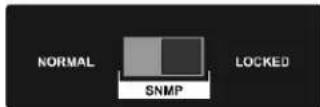
The SNMP Write Lock switch is located on the back of the iMediaChassis/3. The SNMP Write Lock switch prevents a new management board from re-configuring the application module settings (e.g., the status of features such as LinkLoss, FiberAlert, Force mode, etc.) made v SNMP on any previous Management Modules.
| NOTE |
| Leave this switch in the NORMAL position during day-to-day operation; the LOCKED position should only be used when changing the SNMP management board. |
The SNMP Management Module can be removed and replaced as necessary. Refer to the SNMP Management Module manual for complete instructions about how to configure and operate. If an SNMP Management Module is installed, refer to the LED panel below for indicators of Link, Temperature, Power Supply modules and other functions.
SNMP Management Module LEDs
The SNMP Management Module features several LEDs. The LED functions are:
LNK/ACT Glows green when a link is established on port. Blinks green when data activity occurs.
FDX/COL Glows yellow when port is in Full-Duplex mode. Blinks yellow when port is operating in Half-Duplex mode and collisions occur.
TEMP Glows yellow when temperature of unit surpasses a user-defined level.
PS Glows yellow when one power supply module malfunctions.
FAN A / FAN B Glows yellow when a fan malfunctions.

text_image
SNMP Management Module CONSOLE OPTION MGMT TEMP FAN A - PS FAN B FMS/COL UNLOCK IMPACTiMediaChassis/3 Specifications
Input Specifications
| AC 100 to 240V AC, 50/60Hz, 0.75A |
| DC 35V DC to 75V DC Max, 1.6A |
Operating Temperature
| AC 0° | C to 50°C (32°F to 122°F) |
| DC -40 | 0°C to 50°C (-67°F to 122°F) |
Storage Temperature
| AC -40°C to 85°C (-40°F to 185°F) |
| DC -55°C to 125°C (-40°F to 212°F) |
Humidity: 5 to 95% (non-condensing); 0 to 10,000 ft. altitude
Shipping Weight: 5 lbs (2.3 kg)
Dimensions: H=1.73" W=7.50" D=8.74" (4.4 x 19.0 x 22.0 cm)
Hardware Feature Matrix
| Power Supply iMediaChassis/3 | |
| Versions | AC, 2AC, DC, 2DC*, ACDC |
| Type | Fixed |
| End user replaceable No | |
| LEDs Yes | |
| Redundant upgrade on single slot chassis | No |
*Trap can be set for exceeding a temperature value
IMC Networks Technical Support
Tel: (949) 465-3000 or (800) 624-1070 (in the U.S. and Canada);
+32-16-550880 (Europe)
Fax: (949) 465-3020
E-Mail: techsupport@imcnetworks.com
Web: www.imcnetworks.com
| WARNING | |
| Disconnect all power supplies before servicing. | |
Electrostatic discharge (ESD) can cause damage to any product, add-in modules or stand alone units, containing electronic components. Always observe the following precautions when installing or handling these kinds of products
- Do not remove unit from its protective packaging until ready to install.
- Wear an ESD wrist grounding strap before handling any module or component. If the wrist strap is not available, maintain grounded contact with the system unit throughout any procedure requiring ESD protection.
- Hold the units by the edges; do not touch the electronic components or gold connectors.
- After removal, always place the boards on a grounded, static-free surface, ESD pad or in a proper ESD bag. Do not slide the modules or stand alone units over any surface.

WARNING! Integrated circuits and fiber optic components are extremely susceptible to electrostatic discharge damage. Do not handle these components directly unless you are a qualified service technician and use tools and techniques that conform to accepted industry practices.
UL/CUL: Listed to Safety of Information Technology Equipment, including Electrical Business Equipment.
CE: The products described herein comply with the Council Directive on Electromagnetic Compatibility (2004/108/EC) and the Council Directive on Electrical Equipment Designed for use within Certain Voltage Limits (2006/95/EC). Certified to Safety of Information Technology Equipment, Including Electrical Business Equipment. For further details, contact IMC Networks.

text_image
UL LISTED 5M80 ITE E156766 c UL CEEuropean Directive 2002/96/EC (WEEE) requires that any equipment that bears this symbol on product or packaging must not be disposed of with unsorted municipal waste. This symbol indicates that the equipment should be disposed of separately from regular household waste. It is the consumer's responsibility to dispose of this and all equipment so marked through designated collection facilities appointed by government or local authorities. Following these steps through proper disposal and recycling will help prevent potential negative consequences to the environment and human health. For more detailed information about proper disposal, please contact local authorities, waste disposal services, or the point of purchase for this equipment.

natural_image
Symbol of a trash bin with crossed x and y lines, no text or numbers present
natural_image
Abstract red logo design with geometric patterns (no text or symbols)Networks
19772 Pauling • Foothill Ranch, CA 92610-2611 USA
TEL: (949) 465-3000 • FAX: (949) 465-3020
www.imcnetworks.com
ISO 9001:2008 REGISTERED


© 2010 IMC Networks. All rights reserved.
The information in this document is subject to change without notice. IMC Networks assumes no responsibility for any errors that may appear in this document. iMediaChassis Series is a trademark of IMC Networks. Other brands or product names may be trademarks and are the property of their respective companies.
Document Number 50-80954-01 B1 July 2010