Smart-1 5 - Uncategorized Check Point - Free user manual and instructions
Find the device manual for free Smart-1 5 Check Point in PDF.


User questions about Smart-1 5 Check Point
0 question about this device. Answer the ones you know or ask your own.
Ask a new question about this device
Download the instructions for your Uncategorized in PDF format for free! Find your manual Smart-1 5 - Check Point and take your electronic device back in hand. On this page are published all the documents necessary for the use of your device. Smart-1 5 by Check Point.
USER MANUAL Smart-1 5 Check Point
Smart-1 5 & Smart-1 25
Getting Started Guide
Models: S-10, S-21
natural_image
Software blade logo with colorful vertical bars on white background, no text or symbols on the graphic itself8 December 2011
© 2011 Check Point Software Technologies Ltd.
All rights reserved. This product and related documentation are protected by copyright and distributed under licensing restricting their use, copying, distribution, and decompilation. No part of this product or related documentation may be reproduced in any form or by any means without prior written authorization of Check Point. While every precaution has been taken in the preparation of this book, Check Point assumes no responsibility for errors or omissions. This publication and features described herein are subject to change without notice.
RESTRICTED RIGHTS LEGEND:
Use, duplication, or disclosure by the government is subject to restrictions as set forth in subparagraph (c)(1)(ii) of the Rights in Technical Data and Computer Software clause at DFARS 252.227-7013 and FAR 52.227-19.
TRADEMARKS:
Refer to the Copyright page (http://www.checkpoint.com/copyright.html) for a list of our trademarks.
Refer to the Third Party copyright notices (http://www.checkpoint.com/3rd_party_copyright.html) for a list of relevant copyrights and third-party licenses.
Important Information
Latest Software
We recommend that you install the most recent software release to stay up-to-date with the latest functional improvements, stability fixes, security enhancements and protection against new and evolving attacks.
Latest Documentation
The latest version of this document is at:
http://supportcontent.checkpoint.com/documentation_download?ID=12136
For additional technical information, visit the Check Point Support Center
(http://supportcenter.checkpoint.com).
Revision History
| Date | Description |
| 08 December 2011 | New Smart-1 25 appliance.The new Smart-1 25 appliance requires a different software image than the previous appliance. When accessing an image from the Download Center, use theSmart-1 25Bimage.New LCD display and controls ("Front Panel" on page 30)Two high capacity disk drives with improved RAID system ("Hard Disk Drives" on page 33)For the previous Smart-1 25 Getting Started Guide, seeSmart-1 5 and 25 Getting Started Guide(http://supportcontent.checkpoint.com/documentation_download?ID=10949). |
| 23 February 2011 | Dedicated SmartEvent Server option available from R75 only ("Security Management Installation Type" on page 20)Improved formatting and document layout |
| 26 January 2011 | Guide now applies to all Check Point software versions.Added Rack mounting instructions ("Mounting Smart-1 25 in a Rack" on page 11).Updated the First Time Configuration Wizard Instructions ("Using the First Time Configuration Wizard" on page 18) |
| 26 August 2010 | First release of the document |
Feedback
Check Point is engaged in a continuous effort to improve its documentation.
Please help us by sending your comments
(mailto:cp_techpub_feedback@checkpoint.com?subject=Feedback on Smart-1 5 & Smart-1 25 Getting Started Guide).
Health and Safety Information
Read the following warnings before setting up or using the appliance.

Warning - Do not block air vents. A minimum 1/2-inch clearance is required.

Warning - This appliance does not contain any user-serviceable parts. Do not remove any covers or attempt to gain access to the inside of the product. Opening the device or modifying it in any way has the risk of personal injury and will void your warranty. The following instructions are for trained service personnel only.
To prevent damage to any system board, it is important to handle it with care. The following measures are generally sufficient to protect your equipment from static electricity discharge:
- When handling the board, to use a grounded wrist strap designed for static discharge elimination.
- Touch a grounded metal object before removing the board from the antistatic bag.
- Handle the board by its edges only. Do not touch its components, peripheral chips, memory modules or gold contacts.
- When handling processor chips or memory modules, avoid touching their pins or gold edge fingers.
- Restore the communications appliance system board and peripherals back into the antistatic bag when they are not in use or not installed in the chassis. Some circuitry on the system board can continue operating even though the power is switched off.
- Under no circumstances should the lithium battery cell used to power the real-time clock be allowed to short. The battery cell may heat up under these conditions and present a burn hazard.

Warning - DANGER OF EXPLOSION IF BATTERY IS INCORRECTLY REPLACED. REPLACE ONLY WITH SAME OR EQUIVALENT TYPE RECOMMENDED BY THE MANUFACTURER. DISCARD USED BATTERIES ACCORDING TO THE MANUFACTURER'S INSTRUCTIONS.
- Disconnect the system board power supply from its power source before you connect or disconnect cables or install or remove any system board components. Failure to do this can result in personnel injury or equipment damage.
- Avoid short-circuiting the lithium battery; this can cause it to superheat and cause burns if touched.
- Do not operate the processor without a thermal solution. Damage to the processor can occur in seconds.
For California:
Perchlorate Material - special handling may apply. See http://www.dtsc.ca.gov/hazardouswaste/perchlorate
The foregoing notice is provided in accordance with California Code of Regulations Title 22, Division 4.5, Chapter 33. Best Management Practices for Perchlorate Materials. This product, part, or both may include a lithium manganese dioxide battery which contains a perchlorate substance.
Proposition 65 Chemical
Chemicals identified by the State of California, pursuant to the requirements of the California Safe Drinking Water and Toxic Enforcement Act of 1986, California Health & Safety Code s. 25249.5, et seq. ("Proposition 65"), that is "known to the State to cause cancer or reproductive toxicity" (see http://www.calepa.ca.gov)
WARNING:
Handling the cord on this product will expose you to lead, a chemical known to the State of California to cause cancer, and birth defects or other reproductive harm. Wash hands after handling.
Federal Communications Commission (FCC) Statement:
Note: This equipment has been tested and found to comply with the limits for a Class A digital device, pursuant to Part 15 of the FCC Rules. These limits are designed to provide reasonable protection against harmful interference when the equipment is operated in a commercial environment. This equipment generates, uses, and can radiate radio frequency energy and, if not installed and used in accordance with the instruction manual, may cause harmful interference to radio communications. Operation of this equipment in a residential area is likely to cause harmful interference in which case the user will be required to correct the interference at his own expense.
Information to user:
The user's manual or instruction manual for an intentional or unintentional radiator shall caution the user that changes or modifications not expressly approved by the party responsible for compliance could void the user's authority to operate the equipment. In cases where the manual is provided only in a form other than paper, such as on a computer disk or over the Internet, the information required by this section may be included in the manual in that alternative form, provided the user can reasonably be expected to have the capability to access information in that form.
Canadian Department Compliance Statement:
Japan Class A Compliance Statement:
This product is herewith confirmed to comply with the requirements set out in the Council Directive on the Approximation of the Laws of the Member States relating to Electromagnetic Compatibility Directive (2004/108/EC).
This product is in conformity with Low Voltage Directive 2006/95/EC, and complies with the requirements in the Council Directive 2006/95/EC relating to electrical equipment designed for use within certain voltage limits and the Amendment Directive 93/68/EEC.
Product Disposal
natural_image
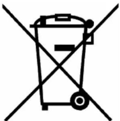
Symbol of a trash bin crossed with two diagonal lines, representing no waste or discharge (no text or labels)This symbol on the product or on its packaging indicates that this product must not be disposed of with your other household waste. Instead, it is your responsibility to dispose of your waste equipment by handing it over to a designated collection point for the recycling of waste electrical and electronic equipment. The separate collection and recycling of your waste equipment at the time of disposal will help to conserve natural resources and ensure that it is recycled in a manner that protects human health and the environment. For more information about where you can drop off your waste equipment for recycling, please contact your local city office or your household waste disposal service.
Important Information....3
Health and Safety Information ....4
Introduction......8
Welcome 8
Smart-1 Overview....8
Security Management Software Blades 8
SmartEvent 9
This document provides: 9
Shipping Carton Contents....9
Terminology....9
SmartEvent Terminology....10
Mounting Smart-1 25 in a Rack....11
Safety Instructions....11
Determining Space and Weight Requirements 12
Rack Mounting Hardware and Required Tools 13
Preparing the Appliance ....14
Attaching the Appliance Rails to the Appliance 14
Attaching the Appliance Ear Brackets (Optional)....15
Attaching the Mounting Brackets to the Slide....15
Attaching the Slide and Mounting Bracket Assembly to the Rack 16
Installing Smart-1 25 in the Rack....17
Configuring Smart-1 18
Connecting the Power Cables and Power On....18
Using the First Time Configuration Wizard ....18
Starting the First Time Configuration Wizard....19
Welcome....19
Appliance Date and Time Setup 19
Network Connections....20
Routing Table 20
DNS and Domain Settings....20
Security Management Installation Type 20
Security Management....21
SmartEvent and SmartReporter Suite Installation Type 21
Web/SSH and GUI Clients Configuration....21
Secure Internal Communication....22
Download SmartConsole Applications 22
Summary 22
Installing the SmartConsole GUI Clients....22
Completing the Configuration 22
Advanced Configuration 23
Connecting to the Smart-1 CLI....23
Configuring SmartEvent....24
Preparing SmartEvent on Security Management Server....24
Configuring the SmartEvent Clients....24
Defining the Internal Network for SmartEvent 25
Defining Correlation Units and Log Servers for SmartEvent....25
Creating a Consolidation Session for SmartReporter 25
Smart-1 Hardware 27
Smart-1 5....28
Front Panel....28
LCD Display Screen....28
Smart-1 25 30
Front Panel....30
LCD Display Screen....30
Hard Disk drives 32
Customer Replaceable Parts....32
Power Supply 32
Hard Disk Drives 33
Removing a Hard Disk Drive....33
Installing a Hard Disk Drive....33
Restoring Factory Defaults 34
Restoring Factory Defaults using the WebUI 34
Restoring Factory Defaults using the Console 34
Restoring Using the LCD Panel 35
Lights Out Management 37
Introduction 38
Initial Login....38
Basic Configuration Options 38
Remotely Controlling the Appliance....38
Remotely Controlling the Power of the Appliance 39
Managing LOM Card Users 39
Configuring LOM Keyboard and Mouse....40
Configuring LOM Network 40
Setting the Date and Time....40
Defining a LOM Login Message 40
Registration and Support....41
Registration....41
Support....41
Where to From Here? 41
Introduction
In This Chapter
Welcome 8
Smart-1 Overview 8
Shipping Carton Contents 9
Terminology 9
SmartEvent Terminology 10
Welcome
Thank you for choosing Check Point's Smart-1. We hope that you will be satisfied with this system and our support services. Check Point products are the most up to date and secure solutions available today.
Check Point also delivers worldwide educational, professional and support services through a network of Authorized Training Centers, Certified Support Partners and Check Point technical support personnel. We make sure that you get the most out of your security investment.
Check Point is committed to ongoing improvement of its products. The new Smart-1 appliance features an improved RAID system.
For more about the Internet Security Product Suite and other security solutions, see the Check Point Web site (http://www.checkpoint.com), or call Check Point at 1(800) 429-4391. For more technical information about Check Point products, consult the Check Point Support Center (http://supportcenter.checkpoint.com).
Welcome to the Check Point family. We look forward to meeting all of your current and future network, application and management security needs.
Smart-1 Overview
Smart-1 appliances deliver Check Point's market leading security management software blades on a dedicated hardware platform specifically designed for mid-size and large enterprise security networks. Based upon Check Point's software blade architecture, Smart-1 appliances deliver a unified management solution for network, IPS and endpoint security with unsurpassed extensibility.
- Provides a comprehensive set of security management Software Blades
- Maximize efficiency with a single unified management console for network and endpoint security
- Reduce costs and conserve resources with up to 12 TB of built-in storage capabilities
- Ensure operational continuity for the most demanding environments
Security Management Software Blades
Smart-1 Appliances includes the following Security Management Software Blades:
• Network Policy Management
• Endpoint Policy Management
- Logging & Status
- SmartProvisioning
- Monitoring
- User Directory
- Management Portal
- SmartEvent (IPS Event Analysis, Reporting and Event Correlation)
SmartEvent
Smart-1 includes SmartEvent, which is made up of IPS Event Analysis, Reporting and Event Correlation. SmartEvent provides centralized reporting and real-time security event correlation and management of your security data. Security teams no longer need to comb through the massive amount of data generated by the devices in their environment. Instead, they can focus on deploying resources on the important threats and trends that pose the greatest risk to their business.
You can configure Smart-1 as a Security Management server with SmartEvent. In R75 and higher, you can also configure Smart-1 as a dedicated server for SmartEvent.
This document provides:
- A brief overview of essential Smart-1 concepts and features
- A step by step guide to getting Smart-1 up and running

Note - Screen shots in this guide may apply only to the highest model to which this guide applies.
Shipping Carton Contents
| Item | Description |
| Appliance | One Smart-1 appliance |
| Rack Mounting Accessories | Hardware mounting kit |
| Cables | • 1 power cable (Smart-1 5)2 power cables (Smart-1 25)• 1 standard LAN cable• 1 RJ-45 console cable |
| Documentation | • User license agreement• Getting Started Guide |
Terminology
The following Smart-1 terms are used in this guide:
- Security Gateway: The security engine that enforces the organization's security policy and acts as a security enforcement point.
- Security Policy: The policy created by the system administrator that regulates the flow of incoming and outgoing communication.
- Security Management server: The server used by the system administrator to manage the security policy. The organization's databases and security policies are stored on the Security Management server and downloaded to the gateway. Smart-1 is a Security Management server.
- SmartConsole: GUI applications that are used to manage various aspects of security policy enforcement. For example, SmartView Tracker is a SmartConsole application that manages logs.
- SmartDashboard: A SmartConsole GUI application that is used by the system administrator to create and manage the security policy.
- Management High Availability (HA): Refers to a configuration in which a primary Security Management server has one or more backup secondary Security Management servers which are ready to take over in case of failure of the primary Security Management server.
SmartEvent Terminology
- SmartEvent and Reporter Suite: Includes SmartEvent and SmartReporter.
- SmartEvent: A system that reads logs and generates events based on an Event Policy. An IPS event-only version is also available. Based on the configuration, SmartEvent contains these components:
- SmartEvent Client (or IPS Event Analysis Client): A GUI that displays events (or IPS events) in many graphical, list and map forms and provides user control of the policy.
- SmartEvent Server (or IPS Event Analysis Server): Holds the event (or IPS event) database, event queries, object values and policy definition.
- SmartEvent Correlation Unit: An engine which reads logs and creates events.
- SmartReporter: A system that reads logs and generates statistical and data reports. SmartReporter contains these components:
- SmartReporter Client: A GUI to generate, define and display reports.
- SmartReporter Server: Contains reports, report definitions and report schedules.
- Log Consolidator: Reads logs, consolidates them according to the consolidation policy and adds them to the SmartReporter database.
Mounting Smart-1 25 in a Rack
These instructions show how to install Smart-1 25 in a standard 19 inch rack.
Safety Instructions
Before installing your appliance in a rack cabinet, review the following guidelines:

- Make sure that the room air temperature is below 35^ (95°F).
- Do not block any air vents. Normally, 15 cm (6 in.) of air space in the rear and 5 cm (2 in.) in the front provides proper airflow.
• Install the appliances in the cabinet starting at the bottom and going up.
• Install the heaviest appliance at the bottom of the rack cabinet. - Do not extend more than one device out of the rack cabinet at the same time.
- Connect the server to a properly grounded outlet.
- Do not overload the power outlet when installing multiple devices in the rack cabinet.
Determining Space and Weight Requirements
Allow sufficient vertical space in the rack for the appliance:
| Model | Height | Weight (Kg) |
| Smart-1 25 | 1U (1.75 inch, 44.5 mm) | 13.5 |
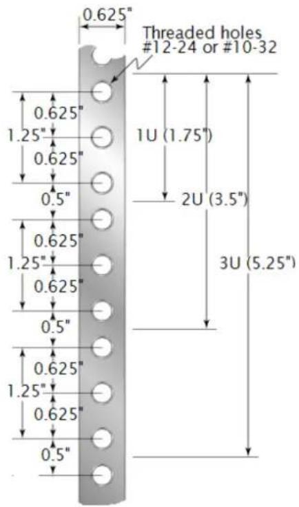
The distance from the center of any hole to the center of the third hole above it is equivalent to 1U. The mounting holes in a standard 19-inch (482.6 mm) server rack rail are arranged as follows:
text_image
0.625" Threaded holes #12-24 or #10-32 0.625" 1.25" 0.625" 0.5" 1U (1.75") 2U (3.5") 0.625" 1.25" 0.625" 0.5" 0.625" 1.25" 0.625" 0.5" 3U (5.25")When installing appliances, start measuring from the center of the two holes with closer spacing. Otherwise, the screw holes on the appliance may not match those on the rack.
Rack Mounting Hardware and Required Tools
text_image
Technical diagram showing three labeled metal bracket components: 1, 2, and 3.| Item | Description | Qty. | Use |
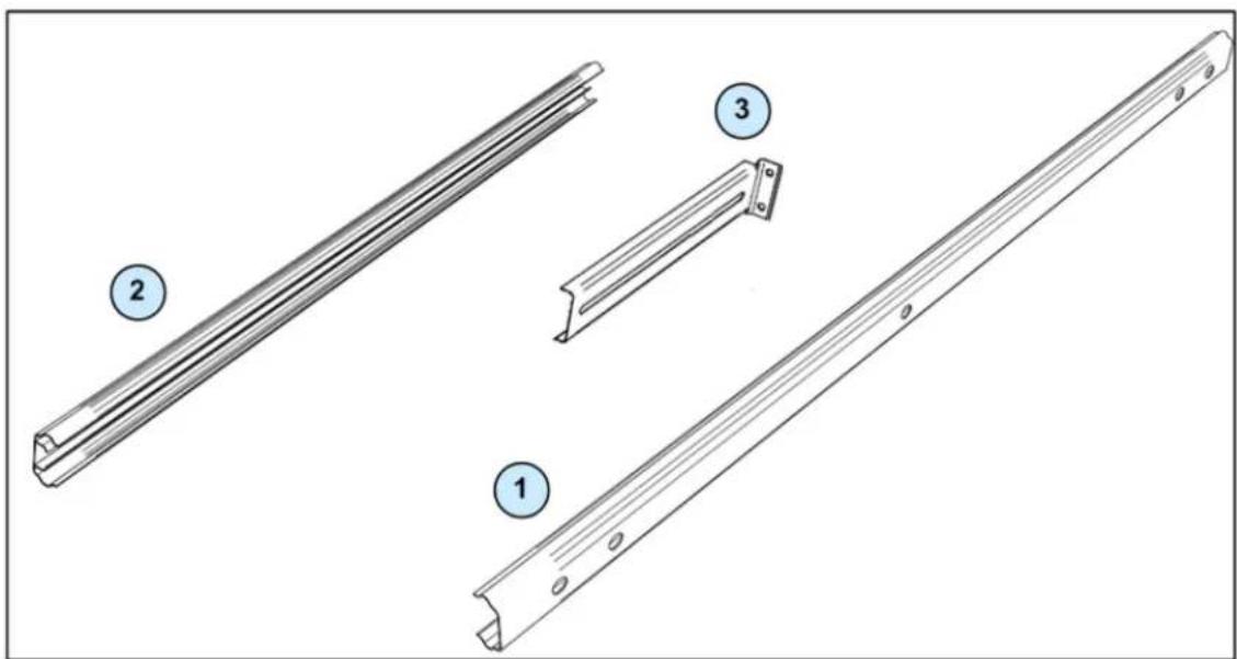
| (1) | Appliance rail | 2 | Attaches to the Smart-1 25 appliance. Out-of-the box it comes combined with the slide. Both appliance rails are identical. |
| Screw (short).RoHS I#6-32*L5-Ni | 6 | Attaches the appliance rail to the appliance | |
| (2) | Slide | 2 | Allows the Smart-1 appliance to slide in and out of the rack for access. Out-of-the box it comes combined with the appliance rail. Both slides are identical. |
| (3) | Mounting bracket | 4 | Mounts the slide to the rack vertical rails. All mounting brackets are identical. |
| Screw (long).RoHS NUT-Flange M4Coating Ni | 8 | Attaches slide to mounting brackets | |
| Threaded washer.RoHS 14.0*L8-Ni | 8 | Attaches slide to mounting brackets | |
| Appliance ear bracket | 2 | Attaches to the Smart-1 25 front panel. Both bracket ears are identical. | |
| Screw | 6 | Attaches the bracket ears to the appliance | |
| Screw | 8 | Attaches mounting brackets to the rack vertical rails. | |
| Washer | 8 | Attaches the mounting brackets to the rack vertical rails. | |
Rack Mounting Tools
- Philips screwdriver. A magnetic head is recommended to hold screws in place and retrieve dropped screws. A powered screwdriver is useful.
- Pliers. Recommended but not essential.
Preparing the Appliance
Prepare the Smart-1 appliance for mounting in the rack. You don't need to do this in the server room.
Attaching the Appliance Rails to the Appliance
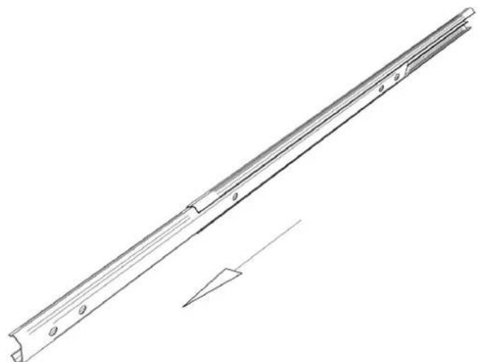
- Separate the appliance rail from the slide. Push a release catch and slide the rail away from the slide until they separate.
natural_image
Technical line drawing of a metal beam with flanged ends and a triangular support (no text or symbols)- Identify the front end. The front end is straight, not grooved. A serial number is engraved near the front end.
-
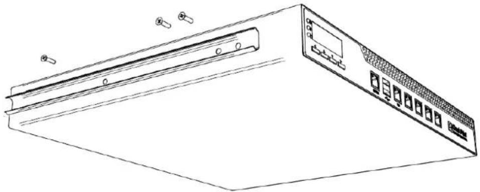
Position the appliance rail on one side of the appliance so that four holes are visible.
-
Attach the appliance rail to the appliance using three screws. One screw at each end, and one screw in one of the two middle holes.
natural_image
Line drawing of a computer monitor with ports and buttons (no text or symbols)- Repeat, to attach an appliance rail to the other side of the appliance.
Attaching the Appliance Ear Brackets (Optional)
The appliance ear brackets are optional. Use them as a
- Handle, to make it easier to grab the front of appliance and slide it in and out.
- Buffer that prevents to appliance jamming in the rack in the closed position.
You can also use the appliance ear brackets to prevent the appliance from sliding in and out of the rack, by attaching the bracket ears to the rack vertical rail.
To connect the two appliance ear brackets to the front of the appliance:
- Attach the appliance ear bracket to one side of the appliance using three screws.
- Repeat for the other side of the appliance.
Attaching the Mounting Brackets to the Slide
Attach the mounting brackets to the slide. You don't need to do this in the server room.
- Open the slide so it is fully extended. Press the latch to extend it.
- Identify the front end and the back end of the slide. There is a piece of black plastic in the front end.
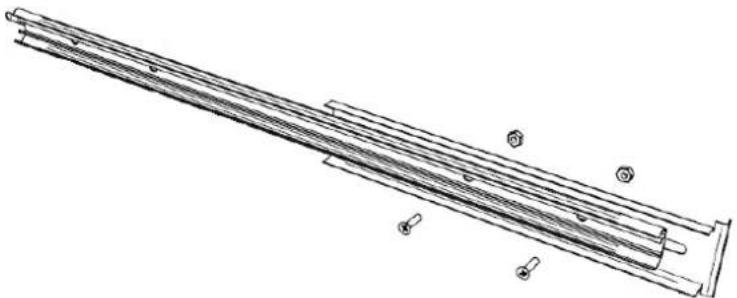
- Attach a mounting bracket loosely to the front of a slide, using two screws and two threaded washers:
a) Close the slide so it is fully retracted.
b) Position a mounting bracket at the front of the slide so you see three holes straight though.
natural_image
Technical line drawing of a mechanical assembly with bolted components (no text or symbols)c) Insert one of the screws through the round hole closest to the front of the slide, then through the slot in the bracket.
d) Place a threaded washer on the screw. Leave it slightly loose. (You will tighten it later).
e) Insert one more screw through the fourth hole in the slide (furthest from the front), then through the slot in the bracket.
f) Place a threaded washer on the screw. Leave it slightly loose. (You will tighten it later).
- Attach a mounting bracket to the back of a slide, using two screws and two threaded washers:
a) Open the slide so it is fully extended.
b) Position a mounting bracket at the back of the slide so you see four holes straight though.
c) Insert one of the screws through the round hole closest to the back of slide, then through the slot in the bracket.
d) Place a threaded washer on the screw, and tighten normally.
e) Insert one more screw through the fourth, oval hole in the slide (furthest from the back), then through the slot in the bracket.
f) Place a threaded washer on the screw, and tighten normally.
- Close the slide so it is fully retracted.
You now have a slide and mounting bracket assembly ready to attach to the rack.
- Repeat for the second slide. Attach one mounting bracket (loosely) to the front of the slide and another (normally) to the back.
Attaching the Slide and Mounting Bracket Assembly to the Rack
Now attach the slide and mounting bracket assembly to the rack:
-
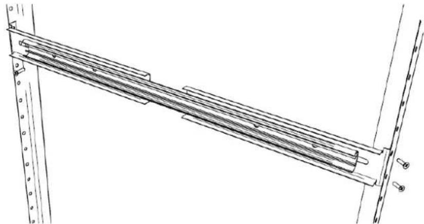
While standing in the front of the rack, place a slide and bracket assembly in position in one side of the rack
-
Attach the mounting bracket to the rack vertical rail at the front using two screws and two washers. Place a washer between screw and the rack.
natural_image
Technical line drawing of a structural beam with support beams and supports (no text or symbols)-
Go to the back of the rack.
-
Extend the slide so that it reaches the vertical rail at the back of the rack
-
Attach the mounting bracket to the rack vertical rail at the back, using two screws and washers.
-
Go the front of the rack.
-
Tighten the screws that attach the slide to the front mounting bracket. These screws were earlier left intentionally loose. You may need to hold the threaded washer with a pair of pliers while you tighten the screw.
-
Repeat for the other side of the rack: Attach the slide and mounting bracket assembly to the other side of the rack
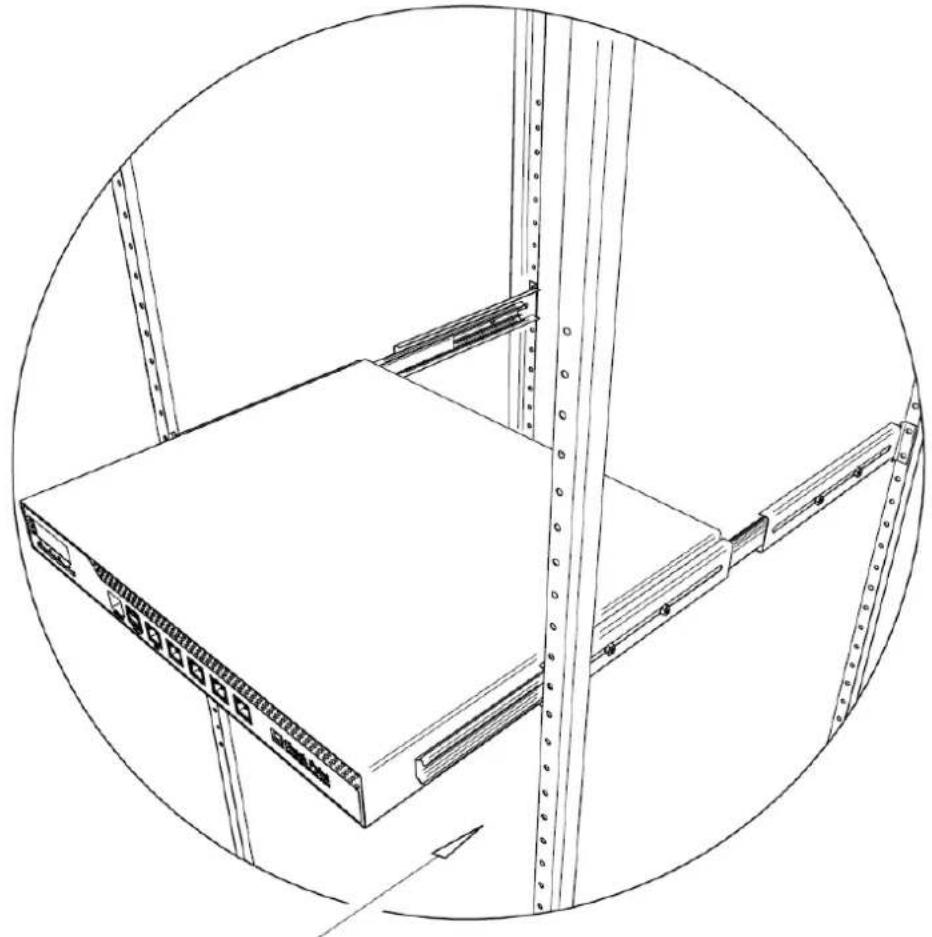
Installing Smart-1 25 in the Rack
-
Extend the slide fully.
-
Carefully line up the appliance with the rail, and push it about half way in. You will hear a click.
-
To slide the appliance fully into the rack, press the slide latch on the left, then on the right. Take care not to trap a finger.
-
Slide the appliance into the rack.
natural_image
Technical line drawing of a server rack unit with mounting brackets and vertical railings (no text or symbols)Configuring Smart-1
The basic workflow for configuring Smart-1 is:
- Connect the cables and power on.
- Perform the initial configuration using the First Time Configuration Wizard.
- Install the SmartConsole GUI clients.
In This Chapter
Connecting the Power Cables and Power On 18
Using the First Time Configuration Wizard 18
Installing the SmartConsole GUI Clients 22
Completing the Configuration 22
Advanced Configuration 23
Connecting the Power Cables and Power On
- Connect the power cable(s).
- Turn on the Power button to start the appliance.

Note - When a power supply fails or is not connected to the outlet, an alarm sounds continuously. If you hear the alarm, check that all power supplies are connected to the outlets. If needed, replace the faulty power supply immediately, and connect the new unit to the A/C outlet. See "Removing the Power Supply (on page 32)".
Using the First Time Configuration Wizard
Perform the initial configuration of Smart-1 using the First Time Configuration Wizard.
At any time, you can click Quit to exit the wizard. Click Next to move to the next page.

Note - When running the First Time Configuration Wizard, you may not see all the pages shown in this section of the guide, and they may not appear in the order shown. The pages that appear in the wizard and their order depend on the Smart-1 software image and on the selections that you make.
Starting the First Time Configuration Wizard
- Connect a standard network cable to the appliance's management interface and to your management network.
The management interface is marked Mgmt. This interface is preconfigured with the IP address 192.168.1.1.
- Connect to the management interface, from a computer on the same network subnet as the management interface.
For example: IP address 192.168.1.x and netmask 255.255.255.0. This can be changed in the WebUI.
- To access the management interface, open a connection from a browser to the default management IP address: https://192.168.1.1:4434.

Note - Pop-ups must always be allowed on https://
The login page opens.
- Log in with the default system administrator login name/password: admin/admin, and click Login.

Note - The features configured in the wizard are accessible after completing the wizard via the WebUI menu. The WebUI menu can be accessed by navigating to https://
- Change the administrator password, as prompted.
The default password is provided to allow to you access to Smart-1. For security purposes, you must change it to a more secure password.
- In the Password recovery login token section, you can download a Login Token that can be used in the event a password is forgotten.
We recommend that you save and store the password recovery login token file in a safe place.
The First-Time Configuration Wizard runs. The Wizard presents a number of windows, in which you are prompted to configure Smart-1.
Welcome
The Welcome page summarizes the steps of the First Time Configuration Wizard.
Appliance Date and Time Setup
Configure date and time in the Date and Time Setup page. Click Apply.
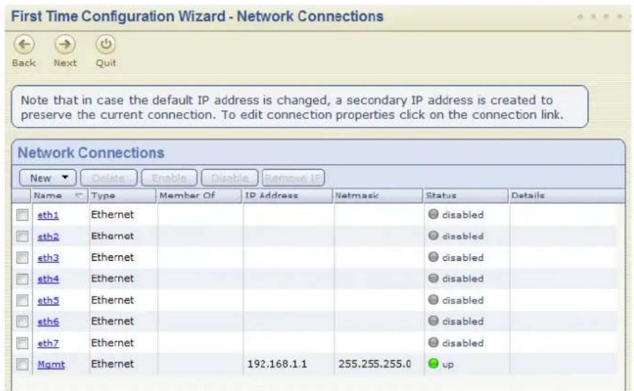
Network Connections
Configure the network connections in the Network Connections page.
text_image
First Time Configuration Wizard - Network Connections Back Next Quit Note that in case the default IP address is changed, a secondary IP address is created to preserve the current connection. To edit connection properties click on the connection link. Network Connections New Delete Enable Disable Remove IP Name Type Member Of IP Address Netmask Status Details eth1 Ethernet sth2 Ethernet sth3 Ethernet sth4 Ethernet sth5 Ethernet sth6 Ethernet sth7 Ethernet Mgmt Ethernet 192.168.1.1 255.255.255.0 upYou can change the Management IP address. Connectivity is maintained with an automatically created secondary interface. You can remove this interface after you complete the wizard in the Network > Network Connections page.
Routing Table
Configure the routing settings on the Routing Table page.
DNS and Domain Settings
Set the Host, Domain and DNS Servers in the DNS and Domain Settings page.
The host name must start with a letter and cannot be named Com1, Com2, ..., Com9.
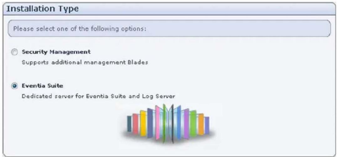
Security Management Installation Type

Note - This page is only available in R75 or higher.
In the Installation Type page:
text_image
Installation Type Please select one of the following options: Security Management Supports additional management Blades Eventia Suite Dedicated server for Eventia Suite and Log Server- Security Management: Configure Smart-1 as a Security Management server with all the management Software Blades, including SmartEvent.
- Eventia Suite (SmartEvent and Reporter Suite): Configure Smart-1 as a dedicated server for SmartEvent, and no other Software Blade. SmartEvent and Reporter Suite contains SmartReporter Server, SmartEvent Server, and SmartEvent Correlation Unit.
Security Management
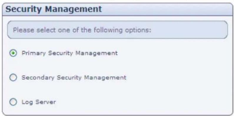
If you choose to install a Security Management server, in the Security Management page:
text_image
Security Management Please select one of the following options: Primary Security Management Secondary Security Management Log Server- Primary Security Management is the Security Management server that will normally be active. To set up a Security Management server in a non-Management HA deployment, choose this option. In a Management HA deployment, if the Primary Security Management server fails, the Secondary Security Management server takes over.
- Secondary Security Management is the Security Management server that takes over if the Primary Security Management server fails. This option applies only in a Management HA deployment.
- Log Server is the repository for log entries generated on gateways. Check Point gateways send their log entries to the Log Server.
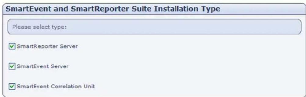
SmartEvent and SmartReporter Suite Installation Type
Configure the SmartEvent and Reporter Suite applications to run on the server.
text_image
SmartEvent and SmartReporter Suite Installation Type Please select type: ✓ SmartReporter Server ✓ SmartEvent Server ✓ SmartEvent Correlation UnitSmartEvent: A system that reads logs and generates events based on an Event Policy. An IPS event-only version is also available. SmartReporter is a system that reads logs and generates statistical and data reports. Choose one or more of these server components:
• SmartReporter Server: Contains reports, report definitions and report schedules.
- SmartEvent Server: Holds the event (or IPS event) database, event queries, object values and policy definition.
- SmartEvent Correlation Unit: An engine which reads logs and creates events.
For IPS Event Analysis, select both SmartEvent Server and SmartEvent Correlation Unit.
Web/SSH and GUI Clients Configuration
Define the clients that are allowed to connect to Smart-1 appliance using a Web browser, SSH client, or SmartConsole applications.
You can define a Host according to Hostname or IP address. Enter Any to manage Smart-1 from anywhere.

Note - It is not recommended to use the Any value for security reasons.
Additional options are available via the WebUI menu, after you complete the First Time Configuration Wizard.
Secure Internal Communication
In the Secure Internal Communication page, enter a SIC Activation Key and remember it, as you will enter it again when configuring the object via SmartDashboard.
Download SmartConsole Applications
Configuring a security policy requires you to install the SmartConsole applications. In the Download SmartConsole Applications window, you can download SmartConsole and install it on Windows machines. For a detailed list of supported Windows operating systems for SmartConsole refer to the release notes of your Check Point version in the Check Point Support Center (http://supportcenter.checkpoint.com).
Summary
The Summary page appears.
Click Finish to complete the First-Time Configuration Wizard. The Appliance automatically restarts. This may take several minutes.

Note - It is recommended to backup the system configuration for system recovery purposes. The backup menu can be accessed via the WebUI interface under the Appliance menu.
Installing the SmartConsole GUI Clients
- The WebUI menu can be accessed by navigating to https://
- Login using the administrator username and password configured in step 4 of the Advanced Initial Configuration step.
- Download the SmartConsole Installation package Product Configuration > Download SmartConsole > Download.
You have now completed the Smart-1 configuration.
To start working with your Smart-1 appliance as a Security Management Server refer to the Security Management Server Administration Guide for your software version in the Check Point Support Center (http://supportcenter.checkpoint.com).
Completing the Configuration
After you have finished the basic configuration of Smart-1, you can configure SmartEvent ("Configuring SmartEvent" on page 24).
Advanced Configuration
Advanced configuration can be done using the sysconfig menu which can only be accessed using the command line interface.

Note - The sysconfig menu is only available after running the First Time Configuration Wizard in the WebUI.
Command line access can be obtained by console connection or through SSH.
Connecting to the Smart-1 CLI
You can connect to the command line interface of the Smart-1 appliance using:
- The provided serial console cable (DTE to DTE) and terminal emulation software such as HyperTerminal (from Windows) or Minicom (from Unix/Linux systems). Connection parameters for Smart-1 appliances are: 9600bps, no parity, 1 stop bit (8N1).
- An SSH connection to the management interface (if SSHD is configured).
Configuring SmartEvent
This section explains how to get up and running with SmartEvent.
In This Chapter
Preparing SmartEvent on Security Management Server 24
Configuring the SmartEvent Clients 24
Preparing SmartEvent on Security Management Server
To configure SmartEvent, first establish connectivity between the components.
-
Launch SmartDashboard.
-
In SmartDashboard, create a new host for each computer that contains a component of SmartEvent:
a) Select Manage > Network Object > New > Check Point > Host
b) In the General Properties window, click Communication and enter the activation key.
Note - If the Security Management Server and SmartEvent are installed on different sides of the firewall, add a rule that allows SIC traffic between them.
c) The version is not entered automatically if the SmartEvent version is newer than the version of the Security Management Server. If so, select the most recent version available from the Version dropdown list.
d) In the Management Software Blades list, select the blades that are installed on the new host.
-
Install the database on all log servers from which SmartEvent reads data: select Policy > Install Database and select the log servers as the targets.
-
To allow the SmartEvent Intro server to block attacks from specific IP addresses, configure the Security Management Server to accept SAM commands from the SmartEvent Intro server:
a) On the Security Management Server, edit the \$CPDIR/conf/sic_policy.conf file:
Search for the section [Inbound rules], and add the following line under # sam proxy:
DN_Mgmt ; Reporting_Tool; ANY; sam ; sslca
b) From the command line in the Security Management Server computer, run the following commands: cpstop cpstart
Configuring the SmartEvent Clients
You must perform these configurations to make the components of the SmartEvent functional.
After you have accomplished the tasks for SmartEvent Intro, events will begin to appear in the SmartEvent Intro client.
After you have accomplished the tasks for SmartReporter, logs will be created and sent to the SmartReporter database. Reports can then be created.
Defining the Internal Network for SmartEvent
To help SmartEvent Intro determine whether events originated internally or externally, the Internal Network must be defined. Certain network objects are copied from the management server to the SmartEvent Intro server during the initial synchronization and updated afterwards periodically. Define the Internal Network from these objects.
Note - If running IPS Event Analysis in a Security Management Server environment, the internal network will be defined automatically from firewall topology information. You can customize the internal network definition.
To define the Internal Network:
- Start the SmartEvent Intro Client.
- From the Policy view, select General Settings > Initial Settings > Internal Network.
- Add objects (hosts, networks, groups, IP ranges) that define your environment's internal network.
Defining Correlation Units and Log Servers for SmartEvent
- From the Policy view of the SmartEvent Intro client, select General Settings > Initial Settings > Correlation Units.
- Select Add.
- Click the button of the Correlation Unit field.
- In the Select Objects window, select a Correlation Unit.
- Click OK.
- Click Add and select the Log Servers available as data sources to the Correlation Unit.
- Select Save.
- From the Actions menu, select Install Events policy.
At this point, SmartEvent Intro will begin to read logs and detect events.
To learn how to manage and fine-tune the system using the SmartEvent Intro Client, see the SmartEvent Administration Guide for your software version on the Check Point Support Center (http://supportcenter.checkpoint.com).
Creating a Consolidation Session for SmartReporter
The Consolidation session reads logs from the log server and adds them to the SmartReporter database.
- If there is a single log server in the environment, the Consolidation session is automatically created.
- If there is more than one log server, you must create the Consolidation session for each log server.
To create a Consolidation session:
- In the Selection Bar view, select Management > Consolidation.
- Select the Sessions tab.
- Click Create New to create a new session.
The New Consolidation Session window appears. - Select the log server from which logs will be collected and will be used to generate reports.
- Click Next.
The New Consolidation Session window appears. - Choose whether to use the default source logs and database tables, or select custom source logs and database tables for consolidation.
If you selected Select default log files and database, click Finish to complete the process. The source of the reports will be preselected logs. The report data will be stored in the default database table named CONNECTIONS. The preselected logs are the sequence of log files that are generated by Check Point products. The preselected logs session will begin at the beginning of the last file in the sequence, or at the point the sequence was stopped.
If you want to customize the Consolidation session refer to the SmartReporter Administration Guide for your software version on the Check Point Support Center (http://supportcenter.checkpoint.com).
Smart-1 Hardware
This chapter provides instructions for installing and removing hardware components on the Smart-1 appliance.
In This Chapter
Smart-1 5 28
Smart-1 25 30
Customer Replaceable Parts 32
Hard Disk Drives 33
Smart-1 5
This section describes the features and components located on the Smart-1 5 appliance.
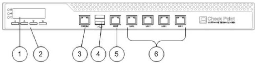
Front Panel
flowchart
graph TD
    A["Switch"] --> B["Check Point"]
    B --> C["1"]
    B --> D["2"]
    B --> E["3"]
    B --> F["4"]
    B --> G["5"]
    B --> H["6"]
    B --> I["Switch 1"]
    B --> J["Switch 2"]
    B --> K["Switch 3"]
    B --> L["Switch 4"]
| Key | Description |
| 1 | LCD display screen |
| 2 | Screen operation keys |
| 3 | Console port - for a serial connection to the appliance using a terminal emulation program such as HyperTerminal |
| 4 | USB ports |
| 5 | Management configuration port |
| 6 | Built-in Ethernet ports (Lan1-Lan4) |
LCD Display Screen
Smart-1 appliances have an LCD screen that lets you do basic management operations. You configure the management IP address, net mask and default gateway using the LCD screen. You can also reboot and turn off the appliance from the LCD screen.
To use the LCD screen operation keys:
| Action | Press |
| Enter the main menu | |
| Navigate within the menu | or |
| Select a menu option | |
| Go back to a previous menu |
To select menu options:
| Menu | Sub-menu | Purpose |
| Network | ||
| Set MGMT IP | Set the management interface IP address | |
| Set Net mask | Set the management interface network mask | |
| Set Default GW | Set the management interface default gateway | |
| System | ||
| Reboot | Reboot the appliance |
To enter an IP address:
| Action | Press |
| Move to the next digit | |
| Move back to the previous digit | |
| Approve the change | when cursor is located on the last digit |
| Cancel the IP change | when cursor is located on the first digit |
| Change current digit | or |
Smart-1 25
This section describes the features and components located on the Smart-1 25 appliance.
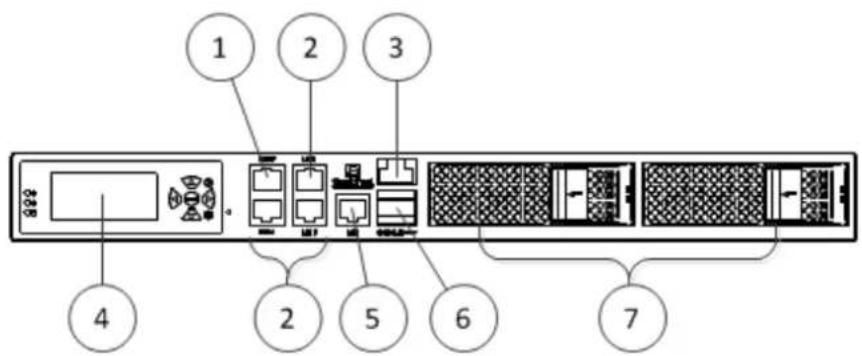
Front Panel
text_image
1 2 3 4 2 5 6 7| Item | Description |
| 1 | Management configuration port |
| 2 | Ethernet connection ports (Lan1 - Lan2) |
| 3 | Console RJ-45 port to connect to a computer using a terminal emulation application |
| 4 | LCD display screen |
| 5 | Lights Out Management (LOM) port |
| 6 | USB ports |
| 7 | Hard disk drives |
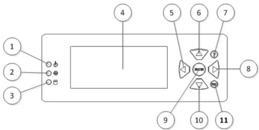
LCD Display Screen
Smart-1 appliances have an LCD screen that lets you do basic management operations. You configure the management IP address, net mask and default gateway using the LCD screen. You can also reboot and turn off the appliance from the LCD screen.
text_image
1 2 3 4 5 6 7 8 9 10 11| Item | Description |
| 1 | On/Off indicator LED |
| 2 | Network Access LED |
| 3 | Disk Access LED |
| 4 | LCD Display |
| 5 | ◀ - Not currently used |
| 6 | ▲- Navigate within a menu |
| 7 | ? - Not currently used |
| 8 | ▶ - Not currently used |
| 9 | Enter - Select a menu option or go to the main menu. |
| 10 | ▼ - Navigate within a menu |
| 11 | Esc - Go back to the previous menu |
To use the menus:
| Action: | Press |
| Enter the main menu | Enter |
| Navigate within the menu | ▲ or ▼ |
| Select a menu option | Enter |
| Go back to a previous menu | Esc |
To select menu options:
| Menu | Sub-menu | Purpose |
| Network | ||
| Set MGMT IP | Set the management interface IP address | |
| Set Net mask | Set the management interface network mask | |
| Set Default GW | Set the management interface default gateway | |
| System | ||
| Reboot | Reboot the appliance |
To enter an IP Address:
| Action | Press |
| Move to the next digit | Enter |
| Move back to the previous digit | Esc |
| Confirm the change | Enter when the cursor is located on the last digit |
| Cancel the IP change | Esc when the cursor is located on the first digit |
| Change current digit | ▲ or ▼ |
Hard Disk drives
The Smart-1 25 appliance contains two 3-1/2", hot-swappable hard disk drives (RAID 1). This lets you do RAID 1 mirroring across the drives using a dedicated LSI Logic RAID controller.
Customer Replaceable Parts
The Smart-1 25 appliance contains these customer replaceable parts:
- Two power supplies
- Two hard disk drives
The Check Point warranty and support agreements do not let you replace parts unless told to do so by a technical support representative. Do not open the Smart-1 case.
Power Supply
This section presents the procedures for removing and installing a power supply unit. The Smart-1 appliance contains two redundant power supplies. It is not necessary to power off the appliance before adding or removing a power supply.
Removing the Power Supply
To remove a power supply unit:
- If the power supply alarm sounds, press the red alarm button to the right of the power supply. This will stop the alarm.
- Remove the power cord.
- Loosen the retaining screw located above the power socket.
- Pull the extraction handle to remove the power supply unit.

Note - Use only the extraction handle to remove the power supply unit. To prevent damaging the power supply, do not pull on the retaining screw, power cord clip or any other part of the unit.
Installing the Power Supply
To install a replacement power supply:
- Insert the power supply into its slot and push firmly until it clicks into place.
- Tighten the retaining screws.
- Insert the power cord.
Hard Disk Drives
The Smart-1 25 appliance contains two 3-1/2", hot-swappable hard disk drives (RAID 1). This lets you do RAID 1 mirroring across the drives using a dedicated LSI Logic RAID controller.
Use the SecurePlatform raidconfig command to do basic maintenance and monitoring procedures on your Smart-1 RAID array.
Usage: raidconfig [status / rebuild /extendstorage / extendfs / alarmon / alarmoff]
- status - Shows the status of RAID controllers and virtual disks.
- rebuild - Rebuild degraded volumes. Use this option after replacing one or more disks in the RAID array.
- alarm - Enable alarm sound.
- alarmoff - Disable alarm sound.
Removing a Hard Disk Drive
The Smart-1 25 contains 2 high-capacity hard disk drive.
You can remove a hard disk drive without risking the integrity of the RAID array or compromising the data.

Warning - Removing the two hard disk drives at the same time will cause the loss of all data!
To remove a hard disk drive:
- Unlock the drive.
- Move the release latch toward the left.
- Remove the drive from its slot.
Installing a Hard Disk Drive
To install a hard disk drive:
- Slide the replacement hard disk drive into the slot.
- Push the extraction handle until it closes and the drive clicks into place.
- If the command raidconfig status shows that the new hard disk drive is not rebuilding, run the command raidconfig rebuild to initiate the rebuild of the RAID array on the new disk drive.
Restoring Factory Defaults
You may restore the factory default images on the appliance using the WebUI, a console connection application (such as HyperTerminal) or the LCD panel.

Important - Restoring factory default images will delete all information on the appliance including images, backup files, and logs.
In This Chapter
Restoring Factory Defaults using the WebUI 34
Restoring Factory Defaults using the Console 34
Restoring Using the LCD Panel 35
Restoring Factory Defaults using the WebUI
Smart-1 contains a default factory image for Security Management Server.
To revert to an earlier image, in the Smart-1 WebUI:
- Click Appliance > Image Management.
- Select the relevant image version you wish to restore.
- Click Revert.
Restoring Factory Defaults using the Console
The below procedure defines how to restore factory defaults using a terminal emulation program such as HyperTerminal.
- Using the supplied serial console cable to the console port, connect Smart-1 to a HyperTerminal machine. In the Port Settings window, the setting for the Serial console is 9600 8N1 (9600 BPS, 8 bits, no parity, 1 stop bit). From the Flow control drop down menu, select Hardware.
- Configure the HyperTerminal parameters.
- In HyperTerminal, click Call > Call to connect to the appliance.
-
Power on Smart-1.
-
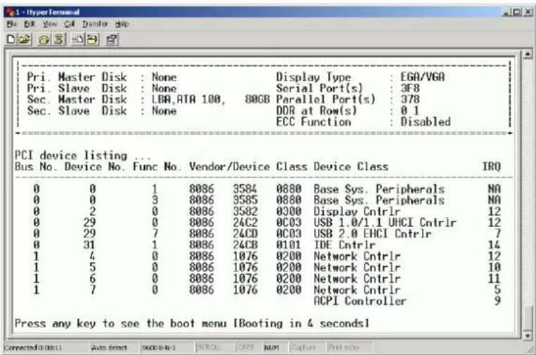
While booting up, the following text appears:
text_image
PCI device listing ... Bus No. Device No. Func No. Vendor/Device Class Device Class IRQ 0 0 1 8086 3584 0880 Base Sys.Peripherals NO 0 0 3 8086 3585 0880 Base Sys.Peripherals NO 0 2 0 8086 3582 0300 Display Cntrlr 12 0 29 0 8086 24C2 0C03 USB 1.0/1.1 UHCI Cntrlr 12 0 29 7 8086 24CD 0C03 USB 2.0 EHCI Cntrlr 7 0 31 1 8086 24CB 0101 IDE Cntrlr 14 1 4 0 8086 1076 0200 Network Cntrlr 12 1 5 0 8086 1076 0200 Network Cntrlr 10 1 6 0 8086 1076 0200 Network Cntrlr 11 1 7 0 8086 1076 0200 Network Cntrlr 5 ACPI Controller 9 Press any key to see the boot menu [Booting in 4 seconds] Connected: Auto detect: S666-8-1: SPOLO: CAPS NUM: Capture: Print now- When this text appears, there are approximately four seconds to press any key in order to bring up the boot grub menu. Once the boot grub menu is displayed, there will be approximately ten seconds to press any key or the machine will continue booting up.
- Scroll down the grub menu to highlight Reset to factory defaults.
Select the relevant default image version.
- Press Enter.
Restoring Using the LCD Panel
To restore the Smart-1 appliance to its default factory configuration using the LCD Panel keys:
- Reboot or power on the appliance.
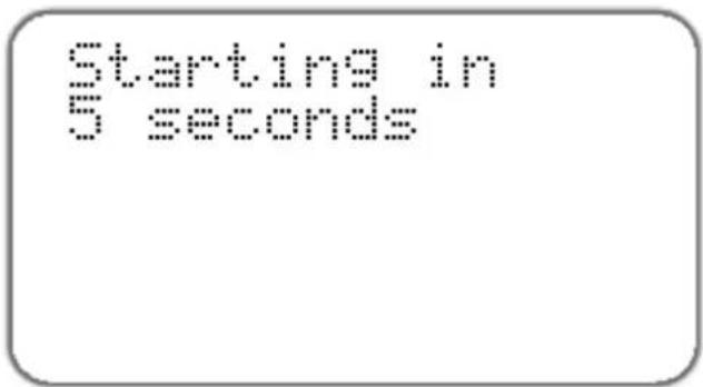
- When the countdown begins, press any of the arrow keys.
text_image
Starting in 5 secondsThe Boot menu appears.
- Using the arrow buttons, scroll to the relevant image version, and then press the UP arrow.
- Confirm the reset by pressing the UP arrow.
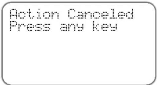
Pressing any other key causes the Action Canceled message to appear:
text_image
Action Canceled Press any keyAt this point, pressing any key returns you to the boot menu.
- Once you have confirmed the reset, wait for the appliance to restore the factory image. While the appliance is restored to the default image, a Reverting image don't turn off message displays continuously.
When the appliance has been restored to its default factory configuration, the appliance reboots and the Initializing message appears.
Initializing
Please wait...
Lights Out Management
This chapter discusses the Lights-Out Management (LOM) integrated card that is supplied with the Smart-1 25 appliance and basic configuration options.
In This Chapter
Introduction 38
Initial Login 38
Basic Configuration Options 38
Remotely Controlling the Appliance 38
Remotely Controlling the Power of the Appliance 39
Managing LOM Card Users 39
Configuring LOM Keyboard and Mouse 40
Configuring LOM Network 40
Setting the Date and Time 40
Defining a LOM Login Message 40
Introduction
The Check Point Lights Out Management (LOM) is an optional card that you can use with Check Point appliances. You can remotely control Check Point appliances using a dedicated management channel. Lights Out Management also works when the appliance is turned off or not responding.
Initial Login
-
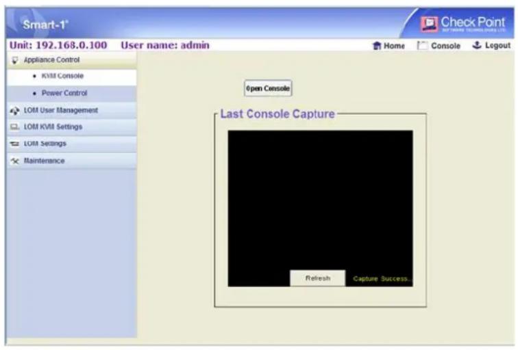
Open a web browser and enter the default IP address of the LOM card: 192.168.0.100. The login window appears.
-
Login with the default User name (admin) and password (admin), all lower case.

Note - Following 30 minutes of inactivity you are automatically be logged out.
text_image
Smart-1* Unit: 192.168.0.100 User name: admin Appliance Control KVMI Console Power Control LOM User Management LOM KVM Settings LOM Settings Maintenance Open Console Last Console Capture Refresh Capture Success... Home Console Logout Check PointBasic Configuration Options
The options in the main menu on Lights Out Management home page let you configure these settings:
- Remotely control the appliance
- Remotely control the power of the appliance
- Manage Lights Out Management users
- Configure Lights Out Management keyboard and mouse settings
- Configure Lights Out Management network settings
- Set date and time
- Define a Lights Out Management login message
Remotely Controlling the Appliance
The Appliance Control menu option enables you to access the appliance via a web interface (Java application). Prior to using this option, ensure that you have Java Runtime installed on the host machine.
To run the remote console:
-
Click the Appliance Control menu option.
-
Select KVM Console and then Open Console. A new window opens that enables you to remotely control the Smart-1 appliance.
Remotely Controlling the Power of the Appliance
Using the LOM card, it is possible to remotely switch ON the Smart-1 appliance even if the power is off, switch OFF the appliance, or reset the appliance.

Note - The main power switch at the rear of the appliance must be turned ON. If the switch is in the OFF position, remote power management is not possible.
To turn ON/OFF or reset the appliance:
- Click the Appliance Control menu option.
- Select Power Control, the relevant option and click Apply Changes.
Managing LOM Card Users
You can create, modify, and delete users. You can also assign privileges to users.
To create a user:
- Click the LOM User Management menu option. The User Management page appears.
- Select a row and click Create. The User Add dialog box appears.
- Enter the following:
- User name: a user name (maximum fourteen characters)
- Password: a password for the login name. The password must have a minimum of 5 and a maximum of 14 characters.
- Confirm Password: confirm the password.
• Network Privileges: assign the Administrator or Operator privileges according to the table below.
Network Privileges
| Administrator | Operator | |
| Login | Yes | Yes |
| Enter KVM console | Yes | Yes |
| Create user | Yes | N/A |
| Modify user | Yes | N/A |
| Delete user | Yes | N/A |
| Date/time settings | Yes | Yes |
| Edit login message | Yes | N/A |
| Remote power management | Yes | Yes |
| Network setting | Yes | N/A |
| Keyboard/mouse setting | Yes | Yes |
To modify a user:
- Select an existing user from the list and click Modify. The User Modify dialog box appears.
- Modify the fields as required.
- To change the password, select Change Password.
- Click Modify User to apply the changes.
To delete a user:
- Select an existing user from the list and click Delete. A message appears.
- Click OK.
Configuring LOM Keyboard and Mouse
To use the remote console feature described above, specify the operating system that the host machine is running.
To configure keyboard and mouse settings:
- Click the KVM Settings menu option.
- Select the relevant option:
• Absolute (for Windows)
- Relative (for Linux)
- Click Apply Changes.
Configuring LOM Network
The network settings option enables you to change the default IP address and other basic network settings of Lights Out Management.
To configure the network settings:
- Click the LOM Settings menu option and select Network.
-
Select Static and enter the following values.
-
IP address: the IP address of the LOM.
- Subnet mask: the subnet mask of the LOM's local network.
- Gateway IP address: the Default Gateway IP address.
- Remote Console and HTTPS port: port number on which the device’s Remote Console server and HTTPS server are listening.
Setting the Date and Time
This option enables you to manually change the date and time of the LOM card.
Defining a LOM Login Message
This option enables you to define the login message that appears when accessing LOM via a browser.
To edit a login message:
- Click the Device Settings menu option and select Login Message.
- Enter the login message text.
- Click Apply Changes.
Registration and Support
In This Chapter
Registration 41
Support 41
Where to From Here? 41
Registration
Smart-1 requires a specific license to operate. Obtain a license and register (http://register.checkpoint.com/cpapp).
The MAC address required to obtain a license is found on the Information > Appliance Status page of the WebUI.
Support
For additional technical information about Check Point products, consult the Check Point Support Center (http://supportcenter.checkpoint.com).
Where to From Here?
You have now learned the basics that you need to get started. The next step is to obtain more advanced knowledge of your Check Point software.
See the relevant documentation for your software version on the Check Point Support Center:
Check Point documentation is available on the Check Point Support Center (http://supportcenter.checkpoint.com).
Be sure to also use the Online Help when you are working with the Check Point SmartConsole clients.