
EKB500 - Keyboard EverFocus - Free user manual and instructions
Find the device manual for free EKB500 EverFocus in PDF.


| Product Type | Universal DVR and Telemetry Keyboard |
| Brand | EverFocus |
| Model | EKB500 |
| Dimensions (W x H x D) | 360 mm x 110 mm x 200 mm |
| Weight | 1.5 kg |
| Power Supply | 12 VDC ±10%, via included power supply (110/230 VAC) |
| Power Consumption | 10 W max. |
| Operating Temperature | 0°C to 40°C, non-condensing |
| Display | 2 lines x 20 characters, double-spaced LCD |
| Keys | 48 keys including numeric keypad, function keys, and dedicated DVR control keys |
| Joystick | 3-axis joystick for pan/tilt/zoom control |
| Jog/Shuttle | Integrated jog dial and shuttle ring for DVR playback control |
| RS-485 Interfaces | 2 independent ports with 2 RJ-45 sockets each (loop-through) |
| RS-232 Interface | 1 x Sub-D9 socket (service/firmware update) |
| Supported Protocols | EverFocus (EVF-1, EVF-2), ED2200/2250 (A-Type/Samsung), Pelco-D, Pelco-P, Panasonic, LG |
| Compatible DVRs | EverFocus EDR series, EDVR series, PARAGON series, EDSR100H/M/400H/M/600/900/1600 |
| Compatible PTZ Cameras | EverFocus EPTZ series, ED2200/2250, Samsung SCC-641/643/6405, Panasonic, LG, Pelco-D/P compatible |
| Maximum Keyboards in System | 8 (one master with ID 0, up to 7 sub-keyboards) |
| Maximum RS-485 Bus Length | 1200 m per bus segment |
| Maximum Devices per Bus | 32 (expandable with distributors) |
| Housing | Designed for countersunk installation |
| Cleaning | Disconnect power; use a damp cloth without acid detergent |
| Safety | Class A product; may cause radio interference; do not open device; operate within specified temperature range |
Frequently Asked Questions - EKB500 EverFocus
User questions about EKB500 EverFocus
0 question about this device. Answer the ones you know or ask your own.
Ask a new question about this device
Download the instructions for your Keyboard in PDF format for free! Find your manual EKB500 - EverFocus and take your electronic device back in hand. On this page are published all the documents necessary for the use of your device. EKB500 by EverFocus.
USER MANUAL EKB500 EverFocus
DVR and Telemetry Keyboard
FW 1.5
New operating concept!
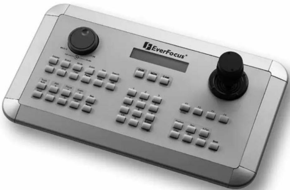
natural_image
Exterior view of a EverFocus brand analog device with control buttons and a digital display (no readable text or symbols beyond branding)1 SAFETY WARNINGS
- Do not place the device near to heaters, furnaces, other heat sources or under direct solar irradiation.
- Operate the device only in locations providing the tolerable operating temperature range 0°C\~40°C.
- For cleaning, make sure the device is plugged off and only use a damp cloth without acid detergent.
• Install the device only in dry and dustproof surroundings. Protect the device against any liquid's penetration. - Avoid the penetration of any artefacts, e.g. through ventilation slots.
- Do not open the device yourself. In case of malfunction, contact your local installer or dealer. Unauthorized opening of the device will annul the warranty claim!
- Use the device only for purposes described in this manual.
- Operate the device only with the power source indicated in the technical data.

ATTENTION! This is a class A product which may cause radio interference in a domestic environment; in this case, the user may be urged to take adequate measures.

This equipment has been tested and found to comply to part 15 of the FCC Rules. These limits are designed to provide reasonable protection against harmful interference in a residential installation. This equipment generates, uses and can radiate radio frequency energy and, if not installed and used in accordance with the instructions, may cause harmful interference to radio communications. However, there is no guarantee that interference will not occur in a particular installation. If this equipment does cause harmful interference to radio or television reception, which can be determined by turning the equipment off and on, the user is encouraged to try to correct the interference by one or more of the following measures:
- Reorient or relocate the receiving antenna.
- Increase the separation between the equipment and receiver.
- Connect the equipment into an outlet on a circuit different from that to which the receiver is connected.
- Consult the dealer or an experienced radio/ TV technician for help.

This Product is RoHS compliant.
WEEE
Your EverFocus product is designed and manufactured with high quality materials and components which can be recycled and reused. This symbol means that electrical and electronic equipment, at their end-of-life, should be disposed of separately from your household waste.
Please, dispose of this equipment at your local community waste collection/recycling centre. In the European Union there are separate collection systems for used electrical and electronic product.
Please, help us to conserve the environment we live in!
The information in this manual was current upon publication. The manufacturer reserves the right to revise and improve his products.
Therefore, all specifications are subject to change without prior notice. Misprints reserved.
Please read this manual carefully before installing and using this unit. Be sure to keep it handy for later reference.
TABLE OF CONTENTS
1 SAFETY WARNINGS....2
2 INTRODUCTION....5
2.1 FEATURES....5
2.2 Changes from FIRMWARE 1.5 compared to former Versions .... 5
2.3 COMPATIBLE DEVICES 5
2.4 DELIVERY SCOPE....6
3 OPERATING ELEMENTS 7
4 KEYBOARD CONNECTORS....8
4.1 RS-485 ports 8
4.2 RS-232 connector....8
4.3 POWER CONNECTOR....8
5 INSTALLATION....9
5.1 General RS-485 bus installation....9
5.2 EPTZ 500 / 1000 / 3000 / 3500 Speed dome camera connection.... 11
5.3 ED-2200, ED-2250, Samsung SCC-641, SCC-643, SCC-6405 connection.... 11
5.4 Connection of Pelco-D / -P protocol-compatible devices 12
5.5 EverFocus DVR connection.... 13
5.6 Connection of several keyboards 15
5.7 START-UP 15
6 MENU SETTINGS....16
6.1 Menu structure 16
6.2 COM PORT SETTING - RS-485 interface setting 17
6.3 DEVICE SETTING....17
6.3.1 Camera setting (changed from FW 1.5)....17
6.3.2 Monitor setting (changed from FW 1.5)....18
6.3.3 DVR Setting 19
6.3.4 Camera List & Delete.... 19
6.3.5 Monitor List & Delete.... 19
6.3.6 DVR List & Delete....20
6.3.7 Non-listed devices 20
6.4 KEYBOARD SETTING....21
6.4.1 Sub Keyboard Setting 21
6.4.2 MENU Password.... 21
6.4.3 Lock password 22
6.4.4 Buzzer ON/OFF 22
6.4.5 Joystick calibration 22
6.4.6 Keypad test 23
6.4.7 Jog & Shuttle test....23
6.4.8 Load default setting....23
6.4.9 Firmware update....23
7 OPERATION....24
7.1 New EKB-500 operation concept (from Firmware 1.5) 24
7.2 MONITOR SELECTION....24
7.3 CAMERA SELECTION 24
7.4 DVR Password input 25
7.5 DVR MAIN MONITOR OPERATION 25
7.6 PTZ OPERATION / SETUP 27
7.6.1 EverFocus EPTZ series 28
7.6.2 EverFocus ED 2200/2250, Samsung El. SCC-641/643/6405 operation .... 33
7.6.3 Pelco-D / -P protocol compatible devices' operation.... 34
7.6.4 LG protocol compatible devices' operation 36
7.6.5 Panasonic protocol compatible devices' operation.... 36
8 SPECIFICATIONS....37
9 APPENDIX A: FACTORY SETTINGS....38
2 INTRODUCTION
The EKB 500 universal keyboard was developed for both DVR remote control and telemetry control of speed domes and telemetry receivers.
Ergonomic key alignment and the integrated jog/shuttle allow the convenient EverFocus DVR operation.
2 independent RS-485 interfaces enable installations with different telemetry protocols.
The new firmware 1.5 allows easier operation also in complex systems with several DVR and PTZ - cameras.
2.1 FEATURES
- independent loop-through RS-485 ports, programmable with different protocols
- Protocol types: EverFocus, ED2200/2250 (Samsung Electr.), Pelco-D, Pelco-P, Panasonic, LG
- 3-axis joystick for convenient pan / tilt / zoom control
- Jog/Shuttle and separate keypad for DVR control
• Housing allows countersunk installation - Integrated double-spaced LCD display
2.2 CHANGES FROM FIRMWARE 1.5 COMPARED TO FORMER VERSIONS
- Main-, Call- and Matrix monitors are operated with same input procedures.
- Cameras are operated with same input procedure for all types of monitors.
- The keyboard detects automatically, if a camera has PTZ function or not and signalize PTZ devices with "PTZ" in the LCD display.
- The keyboard detects automatically, if a selected monitor is a DVR main monitor and signalizes selected main monitors with "DVR" in the LCD display. All DVR related functions such as playback, search, and multiview are active then.
- Telemetry control will switch automatically with selecting a camera, also for main monitor operation.
- The former "DVR-mode" with DVR key is cancelled. DVR key is inactive.
- Even if only Main monitors are installed in the system, all monitors and cameras of the system have to be defined in setup menu.
2.3 COMPATI BLE DEVICES
Digital video recorders:
EverFocus EDR series (except EDR400/1600)
EverFocus EDVR series
EverFocus PARAGON series
EverFocus EDSR100H/M / 400H/M / 600 / 900 / 1600
Speed dome cameras:
EverFocus EPTZ series
EverFocus ED2200 / 2250
Samsung Electronics SCC641 / 643 / 6405
Panasonic
LG (boxed type Autofocus camera series)
VProtect VPTZ series
Pelco-D compatible PTZ devices
Pelco-P compatible PTZ devices
2.4 DELIVERY SCOPE
1 x EKB-500 universal keyboard
1 x 12 VDC power supply
1 x RJ-45 connector, 120 Ohm terminated
1 x RS-485 connection kit incl. connector box and 1 m connection cable
1 x manual
1 x packaging
3 OPERATING ELEMENTS
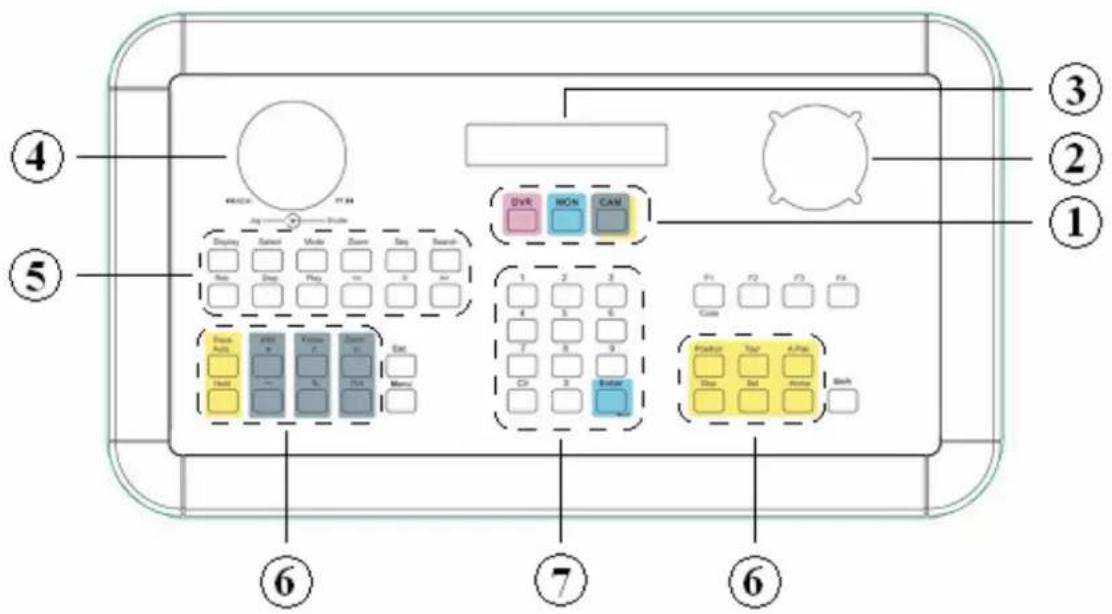
- DVR, MON, CAM
Operation mode toggle key:
DVR: from firmware version 1.5 inactive, function reserved
MON: Selection monitor
CAM: Selection camera
- 3-axis JOYSTICK
Joystick for speed dome and telemetry receiver control
- LCD display
Double-spaced LCD display for status message display
- JOG / SHUTTLE
Operating facility for playback and DVR menu control.
-
DVR control keys
-
Speed dome and telemetry receiver control keys
-
Numeric keypad, CLR, ENTER
0 \~ 9: Numeric keypad for numeric entries
CLR: : Toggle key for speed dome menu termination
ENTER : Enter key for input confirmation.
4 KEYBOARD CONNECTORS
4.1 RS-485 PORTS
EKB-500 provides two independent RS-485 ports with 2 RJ-45 plugs each (loop-through). Pin assignment:
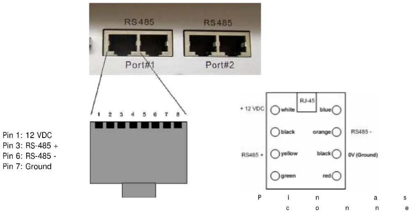
Delivery comprises a connector box for RS-485 and 12 VDC power supply connection enabling power supply connection either directly to the EKB 500 keyboard or through the connector box.
4.2 RS-232 CONNECTOR
The 9-pin Sub-D connector is used for service purposes, e.g. keyboard update with new firmware.
4.3 POWER CONNECTOR
Use the 5,5 mm socket for connecting the 12 VDC power supply. Centre pin is + 12 VDC. The power supply may be installed either through this socket or through the included connector box.
5 INSTALLATION
5.1 GENERAL RS-485 BUS INSTALLATION
EKB 500 uses an RS-485 simplex wiring; the signal is transferred via a single twisted pair line.
CAT5 network cable is recommended, UTP version (unshielded) is sufficient for normal application. A shielded cable should be used if the installed cables are expected to be highly susceptible to interferences.
The number of devices installed in one bus is limited to 32 (expandable through signal distributors), while max. 8 EKB 500 keyboards may be installed in one system.
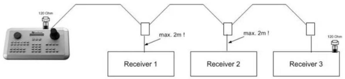
Basically, the bus should be created by serial wiring.

flowchart
graph TD
    A["120 Ohm"] --> B["Receiver 1"]
    A --> C["Receiver 2"]
    A --> D["Receiver 3"]
    B --> E["120 Ohm"]
    C --> E
    D --> E
Maximum RS-485 bus cable length is 1200 m.
flowchart
graph TD
    A["Device"] --> B["120 Ohm"]
    B --> C["Receiver 1"]
    C --> D["max. 2m!"]
    D --> E["Receiver 2"]
    E --> F["max. 2m!"]
    F --> G["Receiver 3"]
    G --> H["120 Ohm"]
Maximum cable length from box to device is 2m using connector boxes.
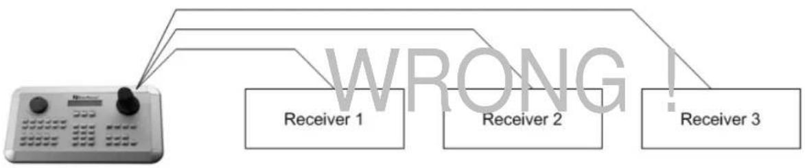
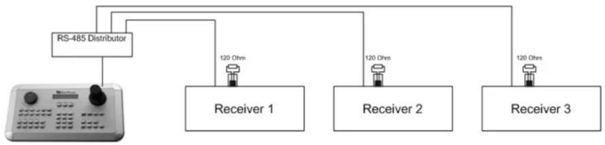
Star wiring is permitted only with signal distributors.
flowchart
graph TD
    A["Device"] --> B["Receiver 1"]
    A --> C["Receiver 2"]
    A --> D["Receiver 3"]
    style A fill:#f9f,stroke:#333
    style B fill:#ccf,stroke:#333
    style C fill:#ccf,stroke:#333
    style D fill:#ccf,stroke:#333
    note1["WRONG!"]
RS-485 signal distributors may be used for star wiring. The maximum system cable length can also be expanded by using these distributors, physically providing a new RS-485 bus with 1200 m cable length each at every distributor output.
flowchart
graph TD
    A["RS-485 Distributor"] --> B["Receiver 1"]
    A --> C["Receiver 2"]
    A --> D["Receiver 3"]
    B -->|120 Ohms| E
    C -->|120 Ohms| F
    D -->|120 Ohms| G
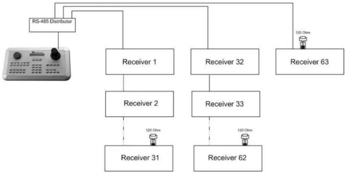
In case the maximum number of 32 bus participants is exceeded, the number of connected devices can be increased by using RS-485 distributors. Each distributor output physically provides one RS-485 bus which enables the additional connection of 31 further devices (the distributor output represents one bus participant itself).
The maximum system expandability depends on the RS-485 address range of the installed devices.
flowchart
graph TD
    A["RS-485 Distributor"] --> B["Receiver 1"]
    A --> C["Receiver 2"]
    A --> D["Receiver 32"]
    A --> E["Receiver 63"]
    B --> F["Receiver 31"]
    C --> G["Receiver 33"]
    D --> H["Receiver 62"]
    E --> I["120 Ohm"]
Attention: Most RS-485 signal distributors (e.g. EDA997A) are unidirectional! This means that the signal only flows from the input towards the outputs. Therefore, e.g. the interconnection of several EKB 500 keyboards is not possible with this signal distributor!
5.2 EPTZ 500 / 1000 / 3000 / 3500 SPEED DOME CAMERA CONNECTION
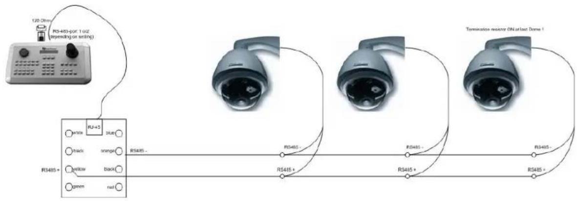
flowchart
graph TD
    A["120 Ohms"] --> B["RS485+ (for 1.0Hz, depending on setting)"]
    B --> C["RS485-"]
    C --> D["RS485+"]
    D --> E["RS485-"]
    E --> F["Temperature monitor ON at last Dome I"]
    style A fill:#f9f,stroke:#333
    style B fill:#ccf,stroke:#333
    style C fill:#cfc,stroke:#333
    style D fill:#fcc,stroke:#333
    style E fill:#cff,stroke:#333
    style F fill:#ffc,stroke:#333
Applied protocol type: EVF2 (standard)
5.3 ED-2200, ED-2250, SAMSUNG SCC-641, SCC-643, SCC-6405 CONNECTION
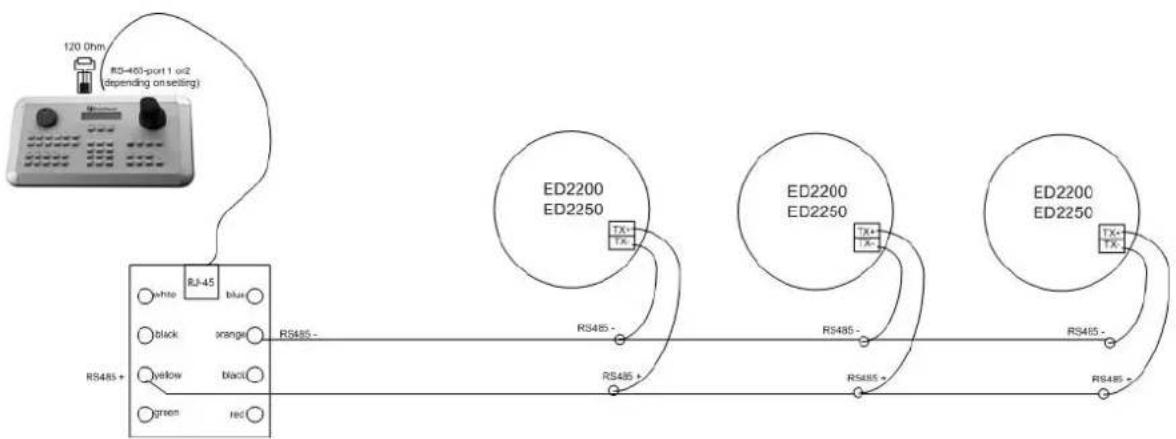
flowchart
graph TD
    A["120.0hm"] --> B["RJ-45-port 1 or2 (depending on selling)"]
    B --> C["RS485+"]
    C --> D["white"]
    C --> E["black"]
    C --> F["yellow"]
    C --> G["green"]
    C --> H["red"]
    B --> I["RJ-45"]
    I --> J["blue"]
    J --> K["orange"]
    K --> L["RS485-"]
    L --> M["RS485+"]
    M --> N["RS485-"]
    N --> O["RS485+"]
    O --> P["RS485-"]
    P --> Q["RS485+"]
    Q --> R["ED2200 ED2250"]
    R --> S["TX+"]
    R --> T["TX-"]
    R --> U["TX+"]
    R --> V["TX-"]
    R --> W["TX+"]
    R --> X["TX-"]
    R --> Y["TX+"]
    R --> Z["TX-"]
Applied protocol type: A-Type
5.4 CONNECTION OF PELCO-D / -P PROTOCOL-COMPATIBLE DEVICES
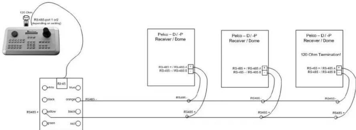
flowchart
graph TD
    A["RS485+"] -->|white| B["RJ-45"]
    A -->|black| B
    A -->|orange| B
    A -->|yellow| B
    A -->|green| B
    A -->|red| B
    B --> C["RS485-"]
    C --> D["R3485+"]
    D --> E["R3485-"]
    E --> F["R3485+"]
    F --> G["R3485-"]
    G --> H["R3485+"]
    H --> I["R3485-"]
    I --> J["R3485+"]
    J --> K["R3485-"]
    K --> L["R3485+"]
    L --> M["R3485-"]
    M --> N["R3485+"]
    N --> O["R3485-"]
    O --> P["R3485+"]
    P --> Q["R3485-"]
    Q --> R["R3485+"]
    R --> S["R3485-"]
    S --> T["R3485+"]
    T --> U["R3485-"]
    U --> V["R3485+"]
    V --> W["R3485-"]
    W --> X["R3485+"]
    X --> Y["R3485-"]
    Y --> Z["R3485+"]
    Z --> AA["R3485-"]
    AA --> AB["R3485+"]
    AB --> AC["R3485-"]
    AC --> AD["R3485+"]
    AD --> AE["R3485-"]
    AE --> AF["R3485+"]
    AF --> AG["R3485-"]
    AG --> AH["R3485+"]
    AH --> AI["R3485-"]
    AI --> AJ["R3485+"]
    AJ --> AK["R3485-"]
    AK --> AL["R3485+"]
    AL --> AM["R3485-"]
    AM --> AN["R3485+"]
    AN --> AO["R3485-"]
    AO --> AP["R3485+"]
    AP --> AQ["R3485-"]
    AQ --> AR["R3485+"]
    AR --> AS["R3485-"]
Basic functions of speed domes and telemetry receivers compatible to Pelco-D / -P protocol can be controlled with the EKB 500 keyboard if a simplex RS-485 connection option is provided. For general connection, please refer to the chart illustrated above.
Applied protocol type: Pelco-D / Pelco-P (in accordance with dome / receiver)
ATTENTION: Some Pelco-D / -P protocol domes and receivers require an address offset of -1 at the keyboard, i.e. the address assigned to the dome / receiver in the EKB 500 menu must be 1 below the address set in the dome / receiver itself!
5.5 EVERFOCUS DVR CONNECTION
The EKB 500 keyboard can control the following digital video recorders:
EDSR series (despite EDSR100 19" model)
EDR series (MPEG-4 series)
EDVR series
Paragon series
Installation with standard network cable:
For short distances, EKB 500 can directly be connected using a standard network cable (patch cable, uncrossed!).
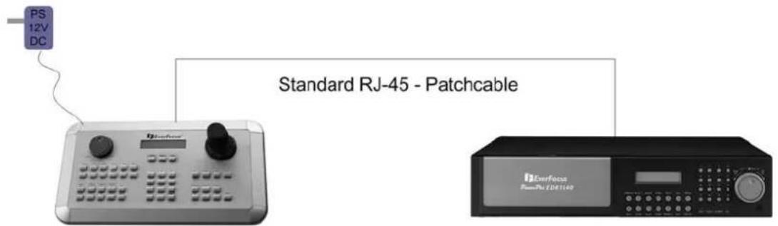
Connection with EDA998 connector kit:
Place the EDA998 connector kit at the RS-485 bus for easy DVR installation.
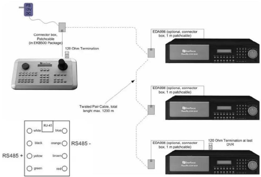
flowchart
graph TD
    A["PS 12V DC"] --> B["Connector box, Patchcable (in EKB500 Package)"]
    B --> C["120 Ohm Termination"]
    D["RS485 +"] --> E["white RJ-45 blue"]
    D --> F["black orange"]
    D --> G["yellow brown"]
    D --> H["green red"]
    I["EDA998 (optional, connector box, 1 m patchcable)"] --> J["ConverFace EDA998"]
    K["EDA998 (optional, connector box, 1 m patchcable)"] --> L["ConverFace EDA998"]
    M["EDA998 (optional, connector box, 1 m patchcable)"] --> N["ConverFace EDA998"]
    O["120 Ohm Termination at last DVR"] --> P["ConverFace EDA998"]
    Q["Twisted Pair Cable, total lenght max. 1200 m"] --> R["EDA998 (optional, connector box, 1 m patchcable)"]
    S["RS485 -"] --> T["White RJ-45 blue"]
flowchart
graph TD
    A["RS-485-port 1 or2 (depending on setting)"] --> B["RS-485+"]
    B --> C["RS485 -"]
    C --> D["RS-485 +"]
    D --> E["RS485 +"]
    E --> F["RS-485 -"]
    F --> G["RS-485 +"]
    G --> H["RS-485 -"]
    H --> I["RS-485 +"]
    I --> J["RS-485 -"]
    J --> K["RS-485 +"]
    K --> L["RS-485 -"]
    L --> M["RS-485 +"]
    M --> N["RS-485 -"]
    N --> O["RS-485 +"]
    O --> P["RS-485 -"]
    P --> Q["RS-485 +"]
    Q --> R["RS-485 -"]
    R --> S["RS-485 +"]
    S --> T["RS-485 -"]
    T --> U["RS-485 +"]
    U --> V["RS-485 -"]
    V --> W["RS-485 +"]
    W --> X["RS-485 -"]
    X --> Y["RS-485 +"]
    Y --> Z["RS-485 -"]
    Z --> AA["RS-485 +"]
    AA --> AB["RS-485 -"]
    AB --> AC["RS-485 +"]
    AC --> AD["RS-485 -"]
    AD --> AE["RS-485 +"]
DVR:
MENU > RS232/RS485:
RS485
BAUD RATE 9600 BPS > Baud rate must be the same as baud rate of
| the | respective | EKB | 500 | port | (defa | |
| or | both | keyboard | and | DVR | is |
STOP BIT 1
PARITY NONE
DATA BIT 8
RS232/RS485 ID 1 > RS-485 address must correspond to
DVR setting in EKB 500 menu
EKB-500: (for details, please refer to "6. MENU SETTINGS")
DVR setting:
MENU (SHIFT + MENU key) > DEVICE SETTING > DVR SETTING > ENTER:
DVR NAME: Selectable DVR number (independent of RS-485 address)
RS485 CONNECTED TO PORT: _ : RS-485 port to which the DVR is connected (1 or 2)
RS485 Address: DVR RS-485 address
(Complies with DVR menu "RS232/RS485 ID")
Must be in accordance with DVR setting
DVR xxxx changed
[ENT] to save ENTER key to press the settings
MENU > COM PORT SETTING > ENTER:
Port: (1 or 2) Enter the RS-485 port to which the DVR is connected
Input the Port (1 or 2)
BAUD: 9600< Baud rate setting (according to DVR)
Protocol: EFV1 Protocol type, setting irrelevant for DVR control> ENTER
Port: 1 Changed
[ENT] to save Press ENTER key to confirm the settings
For details and further settings (e.g. matrix monitor setup), please refer to menu description.
5.6 CONNECTION OF SEVERAL KEYBOARDS
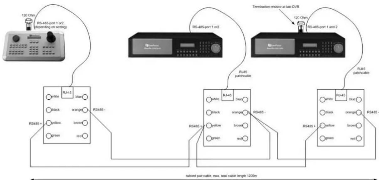
If several keyboards (max. 8) are used in a system, the RS-485 bus has to be looped through from keyboard to keyboard.

flowchart
graph TD
    A["RS-485-port 1/2"] --> B["RJ-45"]
    B --> C["RS-485+"]
    C --> D["RS-485"]
    D --> E["RJ-45"]
    E --> F["RJ-45"]
    F --> G["RJ-45"]
    G --> H["RJ-45"]
    H --> I["RJ-45"]
    I --> J["RJ-45"]
    J --> K["RJ-45"]
    K --> L["RJ-45"]
    L --> M["RJ-45"]
    M --> N["RJ-45"]
    N --> O["RJ-45"]
    O --> P["RJ-45"]
    P --> Q["RJ-45"]
    Q --> R["RJ-45"]
    R --> S["RJ-45"]
    S --> T["RJ-45"]
    T --> U["RJ-45"]
    U --> V["RJ-45"]
    V --> W["RJ-45"]
    W --> X["RJ-45"]
    X --> Y["RJ-45"]
    Y --> Z["RJ-45"]
    Z --> AA["RJ-45"]
    AA --> AB["RJ-45"]
    AB --> AC["RJ-45"]
    AC --> AD["RJ-45"]
    AD --> AE["RJ-45"]
    AE --> AF["RJ-45"]
    AF --> AG["RJ-45"]
Using both RS-485 interfaces (port 1 and 2), the 2nd bus connection must be effected separately as illustrated above by means of EDA-998 connection kits.
Power supply can be installed either directly at the keyboard or with the included connection box.
5.7 START-UP
After having finished the installation work, switch on the power.
During initialisation (approx. 3 sec.), the firmware version is displayed.
Keyboard
Version 1.5
After initialisation, the following message is displayed:
CAM:0001 MON:0001 > DUR
____[CAM/MON] >PTZ
6 MENU SETTINGS
After electrical installation and start-up, both the connected devices and the keyboard itself have to be set up.
Hold the SHIFT key and press the MENU key to enter the keyboard menu.
COM Port Setting
Device Setting
Use the joystick and the ENTER key for menu navigation. Use the ESC key to leave the menu and return from submenus.
The "<" icon at the end of the second line indicated further settings to be effected in this menu. Use the JOYSTICK ↓↑ to switch between the lines.
Selected settings are displayed blinking. Press ENTER to confirm the setting and ESC to return to the previous menu level.
6.1 MENU STRUCTURE
The LCD display menu shows the following structure:
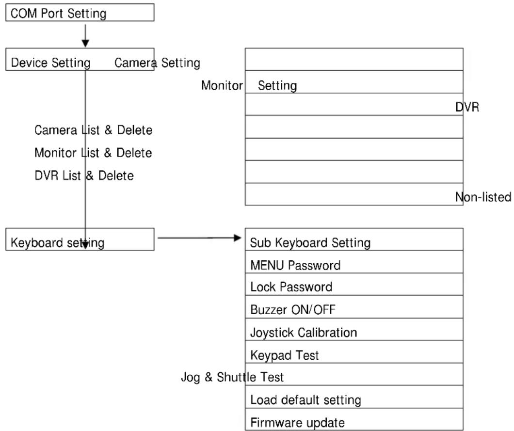
flowchart
graph TD
    A["COM Port Setting"] --> B["Device Setting"]
    B --> C["Camera Setting"]
    C --> D["Monitor"]
    D --> E["Setting"]
    E --> F["DVR"]
    C --> G["Camera List & Delete"]
    C --> H["Monitor List & Delete"]
    C --> I["DVR List & Delete"]
    J["Keyboard setting"] --> K["Sub Keyboard Setting"]
    K --> L["MENU Password"]
    K --> M["Lock Password"]
    K --> N["Buzzer ON/OFF"]
    K --> O["Joystick Calibration"]
    K --> P["Keypad Test"]
    K --> Q["Jette Test"]
    K --> R["Load default setting"]
    K --> S["Firmware update"]
    T["Jog & Shuttle"] --> U["Sub Keyboard Setting"]
    U --> V["MENU Password"]
    U --> W["Lock Password"]
    U --> X["Buzzer ON/OFF"]
    U --> Y["Joystick Calibration"]
    U --> Z["Keypad Test"]
    U --> AA["Jette Test"]
    U --> AB["Load default setting"]
    U --> AC["Firmware update"]
Setting
D
6.2 COM PORT SETTING - RS-485 INTERFACE SETTING
Define telemetry protocol type and transmission rate in this menu.
MENU > COM PORT SETTING > ENTER
Select port 1 or 2 and confirm with ENTER.
Port: _ (1 or 2)
Input the port.
Use the joystick to change the value.
Selection: 1200, 2400, 4800, 9600 Baud.
Press ENTER to confirm the setting and ESC to cancel.
BAUD:9600<
[↑↓] to change
The next menu is used for telemetry protocol setting.
Use the JOYSTICK ↓ ↑ to change the value.
Selection: EVF-1: V-Protect Speed Dome
Protocol: EUF-1
[↑↓] to change
| EVF-2: | EverFocus | EPTZ | series | |
| A-Type: | EverFocus | ED2200/2250, | ||
| Samsung | SCC-641/643/6405 | |||
| P e | I c | o | - | D |
| Pelco-P | ||||
| Panasonic | ||||
| L-Type | LG | Electronics | ||
ATTENTION: Protocol type setting is irrelevant for EverFocus DVR control; only baud rate setting is relevant!
Press ENTER to confirm the selection and ESC t o
c Port:1 Changed c e [ENT] to save
6.3 DEVICE SETTING
Connection settings definition for controlled devices.
6.3.1 Camera setting (changed from FW 1.5)
Use this menu to define telemetry cameras and cameras to be assigned to DVR monitors. In difference to former EKB500 firmware versions this setting is valid for Main- and Call/Matrix - Monitors.
MENU > DEVICE SETTING > CAMERA SETTING > ENTER
Camera number 1 \~ 9999 (independent of RS-485 address!)
Press Enter to confirm the setting and Esc to cancel.
Camera Name: ____
Setup of the RS-485 interface connected to telemetry cameras, port 1 or 2, 0 for OFF (fixed camera). Enter 0 (off) for fixed cameras (numeric entry compulsory). Press Enter to confirm the setting and ESC to cancel.
RS485 Connected to Port: _ [0 (off)], 1, 2]
If 1 or 2 was selected for PORT, the keyboard will automatically recognise this camera as a PTZ device in operation mode.
Enter the RS485 Address of the PTZ camera (this menu item is skipped for fix cameras).
RS485 Address: 001
Setup of DVR and video input to which the camera is connected (requires a DVR installation in the „DVR Setting“ menu) Enter any value if no DVR is connected (numeric entry compulsory).
Press ENTER to confirm the setting and ESC to cancel.
Video Connected to DUR:____ CH:____
6.3.2 Monitor setting (changed from FW 1.5)
In this menu all monitors in the system have to be assigned to DVR monitor outputs. In difference to former firmware versions all monitors have to be defined, including main monitors.
All monitors can only be managed by EKB 500 after definition in this menu. By this, an administration of system access rights for this keyboard can be set up, as only monitors defined in this menu are available for access.
MENU > DEVICE SETTING > MONITOR SETTING > ENTER
[MONITOR NUMBER], entry 1 \~ 99 (independent of DVR monitor number).
Press ENTER to confirm the setting and ESC to cancel.
Monitor Name: ____
The following menu item allows the matrix monitor assignment to the respective DVR's monitor output.
Video Connected to DUR:____ Mon:____
Monitor types:
| EKB-Display DVR - Monitor out | |
| Main | Main monitor |
| Call Call - monitor | |
| M1 Matrix - monitor 1 | |
| M2 Matrix - monitor 2 | |
| M3 Matrix - monitor 3 | |
| M4 Matrix - monitor 4 | |
Press ENTER to confirm the setting and ESC to cancel.
Monitor:1__ changed [ENT] to save
6.3.3 DVR Setting
Define the digital video recorders to be controlled by the keyboard in this menu.
DVRs can only be managed by EKB 500 after definition in this menu. By this, an administration of system access rights can be set up, as only DVRs defined in this menu are available for access.
DVR number, entry 1 \~ 999 (independent of DVR RS-485 address).
Press ENTER to confirm the setting and ESC to cancel.
Setup of the RS-485 interface to which the
DVR is connected, port 1 or 2.
Press ENTER to confirm the setting or ESC to cancel.
DVR RS-485 address (complies with the
Press ENTER to confirm the setting or Esc to cancel.
DVR type selection; select the type by channel number of the DVR.
Use the JOYSTICK ↓ ↑ to adjust the selection.
Attention: For EDSR-400 DVR select "4ch-EDSR", not "4Ch"!
Press ENTER to confirm the selection or ESC to cancel.
DUR Name:____
RS485 Connected to
Port: _ [1 or 2]
RS485 Address:
...... ......
DUR Type:
16Ch <
DUR: 1__ changed
[ENT] to save
6.3.4 Camera List & Delete
This menu contains a list of all installed cameras as well as their settings. Furthermore, cameras can be deleted here.
MENU > DEVICE SETTING >
CAMERA LIST & DELETE > ENTER
After pressing the ENTER key, the first camera is displayed.
Displays: RS-485: port number - RS485 address
DVR: DVR to which the camera is connected
CH: DVR video input
Press ENTER to delete the camera.
Press ESC to return to camera list without deleting.
Total 005 Cameras
[ENT] to view list
Name RS485 DUR CH
012 2-014 002 03<
Delete Camera 012
[ENT] to delete.
Use the JOYSTICK ↓ for camera switching.
Press ESC to cancel.
6.3.5 Monitor List & Delete
This menu contains a list of all installed monitors as well as their settings. Furthermore, monitors can be deleted here.
MENU > DEVICE SETTING >
MONITOR LIST & DELETE > ENTER
Total 005 Monitors
[ENT] to view list
After pressing the ENTER key, the first monitor is displayed.
Displays: Name: monitor number
DVR: DVR to which the monitor is connected.
CH: DVR monitor output
Name DVR Mon
005 004 02 <
Press ENTER to delete the monitor.
Press ENTER again to delete the monitor and return to monitor list.
Press ESC to return to monitor list without deleting.
Del Monitor: 004 [ENT] to delete.
Use the JOYSTICK ↓↑ for monitor switching.
Press ESC to cancel.
6.3.6 DVR List & Delete
This menu contains a list of all installed DVRs as well as their settings. Furthermore, DVRs can be deleted here.
MENU > DEVICE SETTING >
DVR LIST & DELETE > ENTER
After pressing the ENTER key, the first DVR is displayed.
Displays: Name: DVR number
RS-485: port number - RS-485 address
Total 008 DVRs [ENT] to view list
Press ENTER to delete the DVR.
Press ENTER again to delete the monitor and return to monitor list.
Press ESC to return to monitor list without deleting.
Name RS485
004 1-023 <
Use the joystick ↓↑ for DVR switching.
Press ESC to cancel.
Del DVR: 004
[ENT] to delete.
6.3.7 Non-listed devices
This function is currently not supported by EKB-500.
Use this menu to approve / disapprove the control of devices not defined in the menu.
MENU > DEVICE SETTING > NON-LISTED-DEVICE > ENTER
Keep the default setting "No Operation w/o list" at any time, as this function is reserved for future applications only.
Allow Operation w/o list [↑↓] to toggle
No Operation w/o list [↑↓] to toggle
6.4 KEYBOARD SETTING
This menu allows general keyboard and security settings.
6.4.1 Sub Keyboard Setting
This menu provides settings for multiple keyboard installations.
Keep the default value "0" for keyboard ID and number of sub keyboards for single keyboard installation.
For multiple keyboard installations, the keyboards should be assigned to different IDs.
Enter the keyboard ID 0\~7 (one master keyboard with ID 0 required in system) and confirm with ENTER.
If an ID for Subkeyboard (1\~7) was entered, another menu page will open. Enter the total numbers of subkeyboards in the system.
Press ENTER to confirm and exit.
This keyboard ID:0 (0_7,0 for master)
MAX Subkeyboards: 3 (0_7, 0 for master)
6.4.2 MENU Password
The setup menu access can be protected by password.
MENU > KEYBOARD SETTING > MENU PASSWORD > ENTER
Enter a max. 8-character password.
Press ENTER to confirm.
Repeat the password.
Press ENTER to confirm.
For activating the password protection, use the Joystick ^↓ to select "YES" and press ENTER to confirm.
If password protection is activated, the setup menu access requires password entry.
Input new Password:
Repeat Password:
Protect setup menu NO < [↑↓] to change
Setup menu password set and enabled.
6.4.3 Lock password
If this password is activated, the keyboard will lock after 30 seconds with no keyboard operation. Any key press after locking will display a password inquiry at the LCD display.
MENU > KEYBOARD SETTING > LOCK PASSWORD > ENTER
Enter a max. 8-character password.
Press ENTER to confirm.
Repeat the password.
Press ENTER to confirm.
For activating the password protection, use the Joystick ^↓ to select "YES" and press ENTER to confirm.
Lock password is active.
Input new Password:
Repeat Password:
Enable Lock Password NO < [↑↓] to change
Lock password set and enabled.
6.4.4 Buzzer ON/ OFF
MENU > KEYBOARD SETTING > BUZZER ON/OFF > ENTER
Activate / deactivate buzzer.
Use the joystick↓↑for selection and press ENTER to confirm.
Buzzer Enabled [↑↓] to toggle
Buzzer Disabled [↑↓] to toggle
6.4.5 Joystick calibration
MENU > KEYBOARD SETTING > JOYSTICK CALIBRATION > ENTER Use this menu for joystick calibration.
Keep the joystick in idle position and press the ENTER key.
Release Joystick and press [ENT]
Move the JOYSTICK towards all end stops including the third axis (left/right rotation).
Move joystick to corners.
For all X, Y, Z displays, the end stop message must be "OK".
X+000 Y+000 Z+000
X-000 Y-OK Z-000
Press ESC to return to menu.
6.4.6 Keypad test
Use this menu for testing the keys' functionality. MENU > KEYBOARD SETTING > KEYPAD TEST > Enter
Press the keys to be checked.
If the keys work correctly, the LCD display shows the key function in clear text.
Press Esc to return to menu.
[____] Pressed
[Esc] to exit
6.4.7 Jog & Shuttle test
Use this menu for testing the jog/shuttle's functionality. MENU > KEYBOARD SETTING > JOG&SHUTTLE TEST > ENTER
Move the SHUTTLE (outer ring) towards the left and right end stops. The display shows the 7 shuttle steps; reaching the end stop, the display shows >>>>7 (right end stop) resp. <<<7 (left end stop).
Turn the JOG to the left / right. If the JOG works correctly, the display counts from 0 to 9999.
Press ESC to return to menu.
Shuttle: >>> 5
Jog: 9934
6.4.8 Load default setting
Use this menu to reset the keyboard to default setting. MENU > KEYBOARD SETTING > LOAD DEFAULT SETTING> ENTER
Press ENTER to confirm the default setting loading.
Load default setting Press [ENT] to load.
A second security dialogue appears. Enter the figures 1, 2, 3 and press ENTER to confirm. Press ESC to cancel and return to menu.
Input 123 to start
__ [ENT]
After confirmation, all settings are deleted and the keyboard is reset to default setting. A short buzzer blip confirms the reset.
6.4.9 Firmware update
This function allows the loading of new firmware upon availability. A PC with serial interface and an uncrossed RS-232 connection cable (pin 2, 3, 5 interconnected) is required.
MENU > KEYBOARD SETTING > FIRMWARE UPDATE> ENTER
A second security dialogue appears. Enter the figures 1, 2, 3 and press ENTER to confirm. Press ESC to cancel and return to menu.
Input i23 to start
__ [ENT]
7 OPERATION
7.1 NEW EKB-500 OPERATION CONCEPT (FROM FIRMWARE 1.5)
With firmware 1.5 the operation of keyboard will change.
Overview of the changes:
- Main-, Call- and Matrix monitors are operated with same input procedures.
- Cameras are operated with same input procedure for all types of monitors.
- The keyboard detects automatically, if a camera has PTZ function or not and signalize PTZ devices with "PTZ" in the LCD display.
- The keyboard detects automatically, if a selected monitor is a DVR main monitor and signalizes selected main monitors with "DVR" in the LCD display. All DVR related functions such as playback, search, and multiview are active then.
- Telemetry control will switch automatically with selecting a camera, also for main monitor operation.
- The former "DVR-mode" with DVR key is cancelled. DVR key is inactive.
7.2 MONITOR SELECTION
To select a monitor for operation, press
> [MONITOR NUMBER] > MON
or
> MON > [MONITOR NUMBER] > ENTER
CAM-001 MON-01
____[CAM/MON]
If the selected monitor is a DVR main monitor (depending on monitor setup), the LCD display will show ">DVR" in the upper right corner.
CAM-001 MON-04 >DUR
____[CAM/MON]
7.3 CAMERA SELECTION
To select a camera for operation, press
> [CAMERA NUMBER] > CAM
or
> CAM > [camera number] > ENTER
or
> SHIFT (hold) > [camera number]
CAM-001 MON-01
____[CAM/MON]
If the selected monitor is a PTZ camera (depending on camera setup), the LCD display will show ">PTZ" in the upper right corner.
CAM-005 MON-01 >PTZ
____[CAM/MON]
If a PTZ camera was selected together with a DVR main monitor, the display shows: ">DVR" and ">PTZ".
CAM-005 MON-04 >DUR
____[CAM/MON]
7.4 DVR PASSWORD INPUT
If password protection is active in DVR, then the password is entered with the same procedure as described in ch. 7.3 CAMERA SELECTION:
> [CAMERA NUMBER] > CAM
or
> CAM > [camera number] > ENTER
or
> SHIFT (hold) > [camera number]
7.5 DVR MAIN MONITOR OPERATION
If a DVR main monitor is selected, the LCD - Display will show "DVR" in upper right corner.
All DVR functions are active now as described below.
CAM-001 MON-01 >DUR
____[CAM/MON]
EKB-500 provides a separate keypad for DVR control. The keys correspond to the EverFocus DVR front panel keys as regard to labelling and functionality.
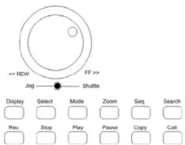
Besides these keys, further keys like MENU or ENTER are required for different functions.
NOTE: For browsing event list pages of DVR the SHUTTLE ring switches with the first step ( 20° movement). Moving the SHUTTLE to the limit may block browsing pages for 1 second.
NOTE: If password protection is active at the DVR, please use DVR key (hold) + [NUMBER] key for password input.
The range of functions varies, depending on the DVR model and firmware version.
The essential functions are described below; for further details please refer to the DVR manual. Please note that this description doesn't provide a full function description of the EverFocus DVRs.
| Function Keys / operation | |
| DVR setup menu | MENU |
| Full screen Input channel number; key 1 is delayed for approx. 1 second to enable input of channels 10~16 | |
| Electronical zoom | ZOOM switches ON / OFF (in full screen mode) |
| Multiscreen display | MODE switches between the available multiscreen displays |
| Record | REC starts the recording mode manually |
| Playback | PLAY starts the playback mode without search |
| Playback search | SEARCH opens the search menu |
| Fast forward / reverse playback | SHUTTLE right (fast forward) resp. SHUTTLE left (fast reverse) in 7 steps, depending on shuttle speed |
| Freeze image playback | PAUSE freezes the image playback |
| Freeze image forward / reverse | JOG left (reverse) resp. right (forward) |
| Stop playback / recording | STOP, first actuation stops the playback, second actuation stops the recording |
| Main monitor status display | DISPLAY switches between the available status displays |
| Sequence | SEQ starts the automatic switching mode |
| Call & matrix monitor setting | CALL enters the setup menu for call and matrix monitors |
| Multiscreen setup Press | SELECT to modify the individual camera screens within a multiscreen by entering the camera number |
| Video export | COPY opens the image export menu |
The operation of speed domes and telemetry receivers requires the setup of these devices in the EKB 500 menu. Settings within the following menus have to be adjusted:
MENU > COM PORT SETTING for interface and protocol type setting
MENU > DEVICE SETTING > CAMERA SETTING for speed dome / telemetry receiver connection settings EKB 500 is optimised for EverFocus EPTZ series speed dome control. Furthermore, basic functions of other supported speed dome types can be operated.
The following operating elements are available for camera control:
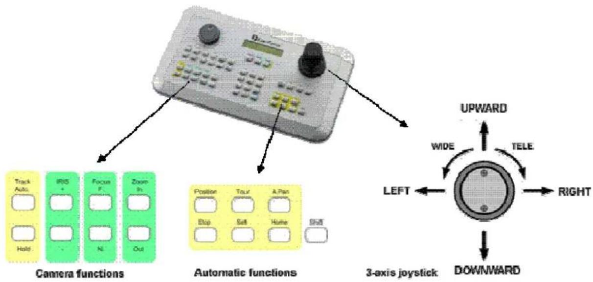
flowchart
graph TD
    A["Camera functions"] --> B["Track Auto"]
    A --> C["IRS +"]
    A --> D["Focus F."]
    A --> E["Zoom In"]
    A --> F["Hold"]
    G["Automatic functions"] --> H["Position"]
    G --> I["Tour"]
    G --> J["A.Pan"]
    G --> K["Stop"]
    G --> L["Selt"]
    G --> M["Home"]
    G --> N["Shift"]
    O["3-axis joystick"] --> P["UPWARD"]
    O --> Q["WIDE"]
    O --> R["TELE"]
    O --> S["LEFT"]
    O --> T["RIGHT"]
    O --> U["DOWNWARD"]
General key description:
TRACK AUTO/HOLD: reserved for future applications
IRIS + / - : manual iris control, + opens iris, - closes iris
FOCUS F. // N.: manual focus, F. TELE; N. WIDE
ZOOM IN/ OUT: Zoom keys, same function as joystick rotation, IN = TELE, OUT = WIDE
POSITION: start and save positions
TOUR: start and save preset tours
A.PAN: autopan, start and save automatic pan operation
STOP: function key for programming termination
SET: switch key for second key level (depending on function)
HOME: start and save home position
SHIFT: switch key for second key level (depending on function)
7.6.1 EverFocus EPTZ series
The following functions are available after camera selection in CAM-MON mode:
CAM:0001 MON:0001
[CAM/MON/DUR]
EPTZ dome operation outline
| Function Keys / operation | |
| Open dome menu | MENU or CAM (hold) + MENU (if Main monitor is selected) |
| Switch menu functions | JOYSTICK↓↑ |
| Change menu settings | JOYSTICK←→ |
| Leave dome menu | CLR (hold) + MENU or menu item EXIT > ENTER |
| Pan - Tilt | JOYSTICK ↓↑ ←→ |
| Zoom TELE / WIDE TELE: | ZOOM IN or JOYSTICK rotation to the rightWIDE: ZOOM OUT or JOYSTICK rotation to the left |
| Focus TELE: | FOCUS F. ; WIDE: FOCUS N. |
| Iris +/- Open iris: | IRIS +/ close iris: IRIS -. |
| Start position (preset) Preset | number + POSITION/ POSITION + preset number > ENTER |
| Save position (preset) | SHIFT (hold) + POSITION > preset number > ENTER |
| Preset parameters | SET (hold) + POSITION |
| Delete preset | CLR (hold) + POSITION |
| Tour mode 1 (one way) | TOUR > number > ENTER |
| Tour mode 2 (back and forth) | SHIFT (hold)+ TOUR > number > ENTER |
| Setup tour | SET (hold) + TOUR |
| Start autopan | A.PAN > speed 1 ~ 239 > ENTER |
| 360° autopan | SHIFT (hold) + A.PAN > speed 1 ~ 239 > ENTER |
| Setup autopan | SET (hold) + A.PAN, ENTER start / end |
| Start home position | HOME |
| Setup home position | SET (hold) + HOME, enter position and time definition |
| Alarm - preset link | F1, enter alarm contact / preset definition |
| Delete alarm - preset link | CLR (hold)+ F1 > alarm 1~4 > ENTER |
7.6.1.1 EPTZ on-screen display
Start EPTZ menu: If DVR Main monitor is selected ("DVR" in LCD - display):
CAM (hold) + MENU
l f n o
MENU or CAM (hold) + MENU
D V R
Switch between the settings:
Change the settings:
Leave the menu: Menu item EXIT > ENTER or
JOYSTICK ↓ ↑
JOYSTICK←→
CLR (hold) + MENU
7.6.1.2 Positions (presets)
Save presets
SHIFT (hold) + POSITION
enter preset number > ENTER
Define preset parameters
SET (hold) + POSITION
enter preset number > ENTER
Camera:0001 Save to
Enter the preset dwell time within preset-tours from 1\~239 seconds
ENTER
Preset travel speed from 1 \~ 239 seconds
ENTER
Enter a preset name (up to 20 characters)
JOYSTICK↓↑ changes the characters
Enter switches to next character
Clr deletes the current character
Set Position:001
Dwell:____[1-239]
Set Position:001
Speed:____[1-239]
Title for position
U
Delete preset
CLR (hold) + POSITION
enter preset number > ENTER
Camera:0001
Del Position:____
Start preset
POSITION > enter preset number > ENTER
Camera:0001 go to
The home position is the position (preset) which is approached after a pre-defined duration upon last speed dome operation.
SET(hold) + HOME
enter inactivity duration 1 \~ 999 minutes
Enter
Use the JOYSTICK to approach the requested position > ENTER
Use the JOYSTICK ↓ ↑ to activate the HOME function.
Back to home if no action for ____Minute
Move to home position [ENT] to confirm
Auto Back Enabled [↑↓] to toggle
7.6.1.4 Autopan
End / stop definition:
SET(hold) + A.PAN
Use the joystick to approach the requested position A, enter the dwell time at this end stop in seconds
(1 \~ 239) > ENTER
Use the JOYSTICK to approach the requested position B, enter the dwell time at this end stop in seconds
(1 \~ 239) > ENTER
Position A Dwell:____[1-239]
Move to Position B [ENT] to confirm
Position B Dwell:____[1-239]
Activate A-B autopan
A.PAN > enter pan speed 1\~239
ENTER
Activate 360^ autopan
A continuous 360° pan operation is also possible.
SHIFT (hold) + A.PAN
enter pan speed 1\~239 > ENTER
Speed:____[1-239] [ENT] to start.
Speed:____[1-239] [ENT] to start.
The EPTZ series supports up to 16 programmable preset tours with up to 16 presets each.
For these tours, 2 operation modes are available:
1) Mode 1 (One way): after approaching all programmed presets, the tour restarts at the first programmed preset.
Example: 1-2-3-4-5-6 > 1-2-3-4-5-6 > 1-2-3-4-5-...
2) Mode 2 (back and forth) > after approaching all programmed presets, the speed dome returns to the presets in reverse order.
Example: 1-2-3-4-5-6 > 5-4-3-2-1 > 2-3-4-5-6 > 5.....
Preset tour programming
SHIFT (hold) + TOUR
enter tour number 1 \~ 16 > ENTER
Enter the presets in correct order (max. 16).
Press ENTER to save and add further preset tours.
Press STOP to finish preset tour programming.
Set Camera:0001
Tour:____[1-16]
Add Position#01:____
[ENT / STOP]
Tour:001 Pos#01:001
[ENT] to save
Activation preset tour mode 1 (One way)
TOUR > enter tour number > ENTER
Camera:0001
Run Tour:____[1-16]
Activation preset tour mode 2 (back and forth)
SHIFT (hold) + TOUR > enter tour number > ENTER
Camera:0001
Run Tour:____[1-16]
7.6.1.6 Alarm contact settings
This function allows the EPTZ dome alarm contact assignment to presets or preset tours.
Program alarm / preset / tour link
F1 > enter alarm contact number 1 \~ 4
Link Alarm: _ [1-4] to Position [↑↓]:____
Use the JOYSTICK ↓ ↑ to switch between preset (position) and preset tour (tour)
Link Alarm: _ [1-4] to Tour [↑↓]:____
Delete alarm / preset / tour link CLR + F1 > enter alarm contact number 1 \~ 4
ENTER
Del AlarmLink:_[1-4] [ENT] to confirm
7.6.2 EverFocus ED 2200/2250, Samsung El. SCC-641/643/6405 operation
Required protocol type in "COM PORT SETTINGS": A-TYPE / SAMSUNG
7.6.2.1 On-screen display
Start menu: If DVR Main monitor is selected ("DVR" in LCD - display):
$$ \text { CAM } (\text { hold }) + \text { MENU } $$
I f n o D V R
$$ \text { MENU or CAM(hold) + MENU } $$
Switch between the settings:
$$ \mathsf {J O Y S T I C K} \downarrow \uparrow $$
Change the settings: JOYSTICK←→
Leave the menu: CLR (hold) + MENU
7.6.2.2 Presets
Preset parameters are defined in the dome menu. Please refer to the manual of the respective model.
Save presets
SHIFT (hold) + POSITION
enter preset number > ENTER
Camera:0001 Save to
The home position is the position (preset) which is approached after a pre-defined duration upon last speed dome operation.
Define the home position within the speed dome's on-screen display. For further details, please refer to the manual of the respective model.
The manual home position start is effected by starting the preset programmed for this function in the dome menu.
The HOME key is inactive with this protocol.
7.6.2.4 Autopan
End stop definition
Define both the end stops and the autopan speed in the speed dome's on-screen display. For further details, please refer to the manual of the respective model.
Start A-B autopan
A.PAN > enter pan speed 1\~239
(any input, value is irrelevant due to speed being defined in the dome menu) > ENTER
Speed:____[1-239]
[ENT] to start.
7.6.2.5 Preset tour / Pattern
Define patterns (stored motion sequences of 30 seconds each) in the speed dome's on-screen display. For further details, please refer to the manual of the respective model.
Activate pattern
Camera:0001
Run Tour:____[1-16]
TOUR > enter pattern number 1\~3 > ENTER
Activate Preset Tour
TOUR > 0 > ENTER
7.6.3 Pelco-D / -P protocol compatible devices' operation
Required protocol type in "COM PORT SETTINGS": Pelco-D / Pelco-P (according to dome / receiver) Implemented protocol is based and tested with Spectra IIITM series halfduplex RS-485. Third party domes with implemented Pelco-D protocol may have different features and
ATTENTION: Some Pelco-D / -P protocol domes and receivers require an address offset of -1 at the keyboard, i.e. the address assigned to the dome / receiver in the EKB 500 menu must be 1 below the address set in the dome / receiver itself!
7.6.3.1 On-screen display
Start menu:
MENU
o PRESET > 95 > ENTER
Switch between the settings:
SHIFT (hold) + JOYSTICK↓↑
Change the settings:
IRIS+
Leave the menu: EXIT entry in OSD menu, confirm with
IRIS +
alternative:
MENU
o PRESET > 95 > ENTER
For exit of some sub-menus the key IRIS - is used.
7.6.3.2 Presets
Save presets
SHIFT (hold) + POSITION
enter preset number > ENTER
Delete preset
CLR (hold) + POSITION
enter preset number > ENTER
Start preset
POSITION> enter preset number > ENTER
Camera:0001 Save to
Define both the end stops and the autopan speed in the speed dome's on-screen display. For further details, please refer to the manual of the respective model.
Start A-B Autopan
A.PAN > enter pan speed 1\~239
(any input, value is irrelevant due to speed being defined in the dome menu)
ENTER
Speed:____[1-239]
[ENT] to start.
ATTENTION: At some third party domes with implemented Pelco-D the Autopan starts with alternative command:
POSITION > 99 > ENTER
7.6.3.4 Frame Scan / Preset tour
Frame scan is a modified Autopan mode, the Autopan stops at defined positions for a programmed time. Settings for this are defined in the speed dome OSD manual. At some third party domes with implemented Pelco-D protocol this command starts Preset tour.
Start Framescan
POSITION > 98 > ENTER
7.6.3.5 Pattern / Preset Tour
Define patterns, which also can contain a preset tour, in the speed dome's on-screen display. For further details, please refer to the manual of the respective model.
Activate pattern
TOUR > enter pattern number > ENTER
Camera:0001
Run Tour:____[1-16]
ATTENTION: At some third party domes with implemented Pelco-D the Preset tour starts with alternative command:
POSITION > 98 > ENTER
7.6.4 LG protocol compatible devices' operation
The EKB-500 supports following functions for boxed type autofocus cameras with LG RS-485 protocol:
Zoom +/- ZOOM IN/ > ZOOM OUT or turn JOYSTICK left / right
F o c u s FOCUS IN / > FOCUS Fa r / f a r
OSD -menu ON/OFF > MENU
Navigation in OSD - menu > ZOOM IN/ > ZOOM OUT // FOCUS N. / > FOCUS F.
IR - Cutfilter ON (day mode) > POSITION > 88 > ENTER
IR - Cutfilter OFF (night mode) > POSITION > 89 > ENTER
IR - Cutfilter Auto > POSITION > 90 > ENTER
Set Camera ID (RS-485 address) >
F1 > [NUMBER] > ENTER
Set Camera New Addr: ____[0-255]
7.6.5 Panasonic protocol compatible devices' operation
The EKB-500 supports following functions for cameras with Panasonic RS-485 protocol.
Limitations for special camera functions are possible.
Please consult the speed dome user manual for usage of special keys such as F1 \~ F4.
Fixed values for communication settings: Wait time: OFF
Interface: No parity, 8 data bit, 1 stop bit
D e l a y t i m
A l a r m d a t
8 SPECIFICATIONS
Keys 48
Joystick 3-axis
Display 2 lines with 20 characters each
RS-485 2 independent RS-485 ports with 2 RJ-45 sockets each
RS-232 1 x RS-232, Sub-D9 socket (service)
RS-485 protocols EverFocus, ED2200/2250, Samsung Electr., Pelco-D,
Pelco-P
LG, Panasonic
Power source 12 VDC +-10%, via power supply 110/230 VAC
Power consumption 10 W max.
Ambient temperature 0°C \~ 40°C, non-condensing
Dimensions 360 (W) x 110 (H) x 200 (D) mm
Weight 1,5
Kg
9 APPENDIX A: FACTORY SETTINGS
PORT settings:
Port 1: 9600 baud, EverFocus
Port 2: 9600 baud, EverFocus
DEVICE SETTINGS / DVR
DVR1: 16Ch., port 1 Addr.1
DVR2: 16Ch., port 1 Addr.2
DVR3: 16Ch., port 1 Addr.3
DVR4: 16Ch., port 1 Addr.4
DVR5: 16Ch., port 1 Addr.5
DVR6: 16Ch., port 1 Addr.6
DEVICE SETTINGS / MONITOR
Mon1: connected to DVR1, MAIN monitor
Mon2: connected to DVR1, CALL monitor
Mon3: connected to DVR1, Matrix 1
Mon4: connected to DVR1, Matrix 2 (M2)
Mon5: connected to DVR1, Matrix 3 (M3)
Mon6: connected to DVR1, Matrix 4 (M4)
Mon7: connected to DVR2, MAIN monitor
Mon8: connected to DVR3, MAIN monitor
Mon9: connected to DVR4, MAIN monitor
Mon10: connected to DVR5, MAIN monitor
Mon11: connected to DVR6, MAIN monitor
DEVICE SETTINGS / CAMERA
Cam1: connected to DVR1, input1, PTZ-ID: 1, Port 1
Cam2: connected to DVR1, input2, PTZ-ID: OFF
Cam3: connected to DVR1, input3, PTZ-ID: OFF
Cam16: connected to DVR1, input16, PTZ-ID: OFF
Cam17: connected to DVR2, input1, PTZ-ID: OFF
Cam32: connected to DVR2, input16, PTZ-ID: OFF
Cam33: connected to DVR3, input1, PTZ-ID: OFF
Cam48: connected to DVR3, input16, PTZ-ID: OFF
Cam49: connected to DVR4, input1, PTZ-ID: OFF
......
Cam64: connected to DVR4, input16, PTZ-ID: OFF
Cam65: connected to DVR5, input1, PTZ-ID: OFF
......
Cam80: connected to DVR5, input16, PTZ-ID: OFF
Cam81: connected to DVR6, input1, PTZ-ID: OFF
......
Cam96: connected to DVR6, input16, PTZ-ID: OFF
PASSWORDS: disabled
BUZZER: ON
EverFocus Electronics Corp.
Head Office:
12F, No.79 Sec. 1 Shin-Tai Wu Road,
Hsi-Chih, Taipei, Taiwan
www.everfocus.com.tw
USA Office:
1801 Highland Ave. Unit A
Duarte, CA 91010, U.S.A.
www.everfocus.com
European Office:
D-46446 Emmerich am Rhein, Germany
www.everfocus.de
China Office:
Room 609, Technology Trade Building,
Shandgdi Information Industry Base,
Haidian District, Beijing, China
www.everfocus.com.cn
Japan Office:
1809 WBG MARIBU East 18F,
2-6 Nakase.Mihama-ku.
Chiba city 261-7118, Japan
www.everfocus.com

EverFocus®
- DVR and Telemetry Keyboard
- SAFETY WARNINGS
- WEEE
- TABLE OF CONTENTS
- INTRODUCTION
- FEATURES
- CHANGES FROM FIRMWARE 1.5 COMPARED TO FORMER VERSIONS
- COMPATI BLE DEVICES
- DELIVERY SCOPE
- OPERATING ELEMENTS
- KEYBOARD CONNECTORS
- RS-485 PORTS
- RS-232 CONNECTOR
- POWER CONNECTOR
- INSTALLATION
- GENERAL RS-485 BUS INSTALLATION
- EPTZ 500 / 1000 / 3000 / 3500 SPEED DOME CAMERA CONNECTION
- ED-2200, ED-2250, SAMSUNG SCC-641, SCC-643, SCC-6405 CONNECTION
- CONNECTION OF PELCO-D / -P PROTOCOL-COMPATIBLE DEVICES
- EVERFOCUS DVR CONNECTION
- DVR:
- DVR setting in EKB 500 menu
- CONNECTION OF SEVERAL KEYBOARDS
- START-UP
- MENU SETTINGS
- MENU STRUCTURE
- COM PORT SETTING - RS-485 INTERFACE SETTING
- DEVICE SETTING
- Camera setting (changed from FW 1.5)
- Monitor setting (changed from FW 1.5)
- DVR Setting
- Camera List & Delete
- Monitor List & Delete
- DVR List & Delete
- Non-listed devices
- KEYBOARD SETTING
- Sub Keyboard Setting
- MENU Password
- Lock password
- Buzzer ON/ OFF
- Joystick calibration
- Keypad test
- Jog & Shuttle test
- Load default setting
- Firmware update
- OPERATION
- NEW EKB-500 OPERATION CONCEPT (FROM FIRMWARE 1.5)
- Overview of the changes:
- MONITOR SELECTION
- CAMERA SELECTION
- DVR PASSWORD INPUT
- DVR MAIN MONITOR OPERATION
- General key description:
- EverFocus EPTZ series
- EPTZ on-screen display
- Positions (presets)
- Save presets
- Delete preset
- Start preset
- Autopan
- End / stop definition:
- Alarm contact settings
- EverFocus ED 2200/2250, Samsung El. SCC-641/643/6405 operation
- On-screen display
- Presets
- Autopan
- Preset tour / Pattern
- Pelco-D / -P protocol compatible devices' operation
- On-screen display
- Presets
- Frame Scan / Preset tour
- Pattern / Preset Tour
- Activate pattern
- LG protocol compatible devices' operation
- Panasonic protocol compatible devices' operation
- SPECIFICATIONS
- APPENDIX A: FACTORY SETTINGS
- PORT settings:
- DEVICE SETTINGS / DVR
- DEVICE SETTINGS / MONITOR
- DEVICE SETTINGS / CAMERA
- EverFocus Electronics Corp.
- Head Office:
- USA Office:
- European Office:
- China Office:
- Japan Office:
Brand : EverFocus
Model : EKB500
Category : Keyboard