8242-9 - Uncategorized Omnitron - Free user manual and instructions
Find the device manual for free 8242-9 Omnitron in PDF.


User questions about 8242-9 Omnitron
0 question about this device. Answer the ones you know or ask your own.
Ask a new question about this device
Download the instructions for your Uncategorized in PDF format for free! Find your manual 8242-9 - Omnitron and take your electronic device back in hand. On this page are published all the documents necessary for the use of your device. 8242-9 by Omnitron.
USER MANUAL 8242-9 Omnitron
OSt Omnitron Systems Technology, Inc.
iConverter®
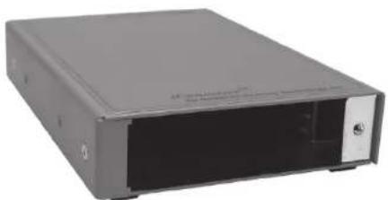
1-Module Power Chassis
natural_image
Exterior view of a gray rectangular electronic device with a black cover and indicator lights (no visible text or symbols)User Manual
140 Technology Dr., #500 Irvine, CA 92618 USA Phone: (949) 250-6510; Fax: (949) 250-6514
Warning
The operating description in this Instruction Manual is for use by qualified personnel only. To avoid electrical shock, do not perform any servicing of this module other than that contained in the operating instructions, unless you are qualified and certified to do so by Omnitron Systems Technology, Inc.
Caution
All user-required operations can be performed without opening the chassis. Never attempt to open or remove the cover or tamper with the chassis. There are no user replaceable or serviceable parts in this unit. Equipment is not intended to be installed and used in a place (home, school, or public area) accessible to the general population.
Warranty
This product is warranted to the original purchaser against defects in material and workmanship for a period of TWO YEARS from the date of shipment. A LIFETIME warranty may be obtained by the original purchaser by REGISTERING this product with Omnitron within 90 days from the date of shipment. TO REGISTER, COMPLETE AND MAIL OR FAX THE ENCLOSED REGISTRATION FORM. Or you may register your product on the Internet at http://www.omnitron-systems.com. During the warranty period, Omnitron will, at its option, repair or replace a product which is proven to be defective.
For warranty service, the product must be sent to an Omnitron designated facility, at Buyer's expense. Omnitron will pay the shipping charge to return the product to Buyer's designated US address using Omnitron's standard shipping method.
Limitation of Warranty
The foregoing warranty shall not apply to defects resulting from improper or inadequate use and/or maintenance of the equipment by Buyer, Buyer-supplied equipment, Buyer-supplied interfacing, unauthorized modifications or tampering with equipment (including removal of equipment cover by personnel not specifically authorized and certified by Omnitron), or misuse, or operating outside the environmental specification of the product (including but not limited to voltage, ambient temperature, radiation, unusual dust, etc.), or improper site preparation or maintenance. No other warranty is expressed or implied. Omnitron specifically disclaims the implied warranties of merchantability and fitness for any particular purpose.
Exclusive Remedies
The remedies provided herein are the Buyer's sole and exclusive remedies. Omnitron shall not be liable for any direct, indirect, special, incidental, or consequential damages, whether based on contract, tort, or any legal theory.
iConverter
1-Module Power Chassis User Manual
1.0 GENERAL DESCRIPTION
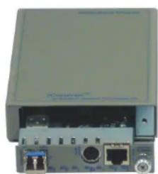
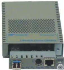
The 1-Module iConverter Power Chassis supports a single iConverter module and is powered by an external AC power adapter or an external DC power source (20 to 60VDC).
natural_image
Front view of a network device showing ports and connectors (no visible text or labels)Model 8240-x and 8241-x
natural_image
Front view of a network device with ports and ventilation grille (no visible text or symbols)Model 8242-x and 8243-x
Fig. 1 1-Module Power Chassis (Shown without modules installed)
This User Manual describes the following models:
| Chassis Type | 1-Module Chassis US AC Adapter | 1-Module Chassis Universal AC Adapter | 1-Module Chassis US AC Adapter | 1-Module Chassis Universal AC Adapter | 1-Module Chassis 48VDC |
| 1-Module Chassis | 8240-1(3.3 Watts) | 8240-2(3.3 Watts) | 8242-1(8.3 Watts) | 8242-2(8.3 Watts) | 8242-9(8.3 Watts) |
| 1-Module Chassis with Dying Gasp Support | 8241-1(5 Watts) | 8241-2(5 Watts) | 8243-1(8.3 Watts) | 8243-2(8.3 Watts) | 8243-9(8.3 Watts) |
| Wall-Mount Hardware Kit | 8249-0 | ||||
| DIN Rail Mounting Kit | 8250-0 | ||||
| NEBS Grounding Kit N/A 9123-0 | |||||
| For wide temperature (-40 to 60°C) add a "W" to the end of the model number.Consult factory for extended temperature (-40 to +75°C) models. | |||||
1.1 Dying Gasp Trap
The 8241-1, 8241-2, 8243-1, 8243-2 and 8243-9 chassis feature Dying Gasp Trap, which reports loss of power input or chassis power supply failure. This feature requires an iConverter management module be installed in the chassis. When power failure occurs, the chassis reserves enough power to keep the installed module running in order to send a final SNMP alert to the management software.
3.0 INSTALLATION
3.1 Installing Module
Carefully slide the module into the open slot in the chassis. Align the module with the installation guides and ensure that the module is firmly seated against the backplane. Secure the module by fastening the front panel thumbscrew (push in and turn clockwise to tighten) to the chassis front.
3.2 AC Powered Chassis
To power the unit using the AC/DC adapter, connect the AC/DC adapter to the AC outlet. Then connect the barrel plug at the end of the wire on the AC/DC adapter to the DC barrel connector (center-positive) on the unit. Route the power cable through the provided strain relief for additional support. Confirm that the unit has powered up properly by checking the Power LED located on the front of the installed module. Use only the supplied AC/DC power adapter to power the chassis.
NOTE: The 8242-x and 8243-x models use a different AD/DC power adapter than the 8240-x and 8241-x models. The DC barrel connector on the 8242-x and 8243-x is a 2.1mm center connector and supplies a nominal 48VDC. The DC barrel connector on the 8240-x and 8241-x is a 2.5mm center connector and supplies a nominal 9VDC.
If installing with the NEBS Mounting Kit for 8242-x and 8243-x models, secure the grounding wire to the ground lug. See Figure 2 for the location of the grounding lug.

text_image
NEBS Grounding Strain Relief Barrel ConnectorFig. 2 Rear of 1-Module Power Chassis, Models 8242-x and 8243-x with AC Power Connector
3.3 DC Powered Chassis Site Preparation
Power source should be available within 5 ft. of the chassis. The over current protection for connection with centralized DC shall be provided in the building installation, and shall be a UL listed circuit breaker rated 20 Amps, and installed per the National Electrical Code, ANSI/NFPA-70.
This equipment requires 20-60VDC/0.6Amp rated power. Appropriate overloading protection should be provided on the DC power source outlets utilized.
WARNING: Only a DC power source that complies with safety extra low voltage (SELV) requirements can be connected to the DC-input power supply.
- This equipment shall be connected to the DC supp earthing electrode conductor or to a bonding jumper earthing terminal bar or bus to which the DC supp earthing electrode is connected.
This equipment shall be located in the same immed (such as adjacent cabinets) as any other equipment a connection between the earthed conductor of the supply circuit and the earthing conductor, and also of earthing of the DC system. The DC system shall be earthed elsewhere. - The DC supply source is to be located within the same premises as this equipment.
There shall be no switching or disconnecting devices earthed circuit conductor between the DC source and the earthing electrode conductor.
The standard operating temperature of this equipment is 0 to 50 degrees C. If installed in a closed or multi-module rack assembly, the operating ambient temperature of the rack must not exceed the maximum rated 50 degrees C. See specifications on page 7 for wide temperature ranges.
Installation of the equipment should be such that the air flow in the front, back and top vents of the chassis are not compromised or restricted.
Never use this equipment to carry any weight except its own. Never use it as a shelf to support weight of other equipment.
3.4 DC Powered Chassis Mounting
Locate the DC circuit breaker of the external power source, and switch the circuit breaker to the OFF position.
Prepare a power cable using a three conductor insulated wire (not supplied) with a 14 AWG gauge minimum. Cut the power cable to the length required.
Strip approximately 3/8 of an inch of insulation from the power cable wires.
Connect the power cables to the iConverter Chassis by fastening the stripped ends to the DC power connector. Route the power cables through the provided strain relief for additional support.
WARNING: Note the wire colors used in making the positive, negative and ground connections. Use the same color assignment for the connection at the circuit breaker.
Connect the power wires to the circuit breaker and switch the circuit breaker ON. If any modules are installed, their Power LED should indicate the presence of power.
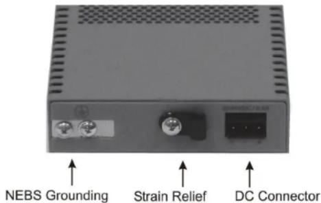
If installing with the NEBS Mounting Kit for 8242-9 and 8243-9 models, secure the grounding wire to the ground lug. See Figure 3 for the location of the grounding lug.
text_image
NEBS Grounding Strain Relief DC ConnectorFig. 3 Rear of 1-Module Power Chassis, Models 8242-9 and 8243-9 with DC Power Connector
WARNING!!!
NEVER ATTEMPT TO OPEN THE CHASSIS OR SERVICE THE POWER SUPPLY. OPENING THE CHASSIS MAY CAUSE SERIOUS INJURY OR DEATH. THERE ARE NO USER REPLACEABLE OR SERVICEABLE PARTS IN THIS UNIT.
4.0 SPECIFICATIONS
| Model Number 8240-1 / | 8241-1 | 8240-2 /8241-2 | 8242-1 /8243-1 | 8242-2 /8243-2 | 8242-9 /8243-9 |
| Module Capacity 1 | |||||
| Power Supply Type Wall | Power Supply | Tabletop Power Supply | Tabletop Power Supply | Tabletop Power Supply | User Supplied |
| Power Supply Connector | US Plug IEC | 320Socket | US Power Cord | EC 320Socket | 3 Position Terminal |
| Power Requirements | 120VAC / 60Hz0.2A @120VAC | 100 to 240VAC50 / 60Hz0.2A @120VAC | 120VAC / 60Hz1.0A @120VAC | 100 to 240VAC50 / 60Hz1.0A @120VAC | 20 to 60VDC*0.6A Max |
| Dimensions W: 3.8" x D: 5.5" x H: 1.0" W: 3.8" x D: 6.0" x H: | 1.0" | ||||
| Weight 1.5 lbs. | |||||
| Compliance UL, CE, FCC Class A, NEBS Level 3 | |||||
| Temperature Standard Operating Wide Operating | 0 to 50°C-40 to 60°C | ||||
| Humidity 5 to 95% (non-condensing) | |||||
| Altitude -100m to 4,000m | |||||
| MTBF (hrs) | 250,000 | 100,000 | 260,000 | 260,000 | 2,700,000 |
* Effective range is 18 to 60VDC when using a module without dying gasp support.
5.0 CUSTOMER SUPPORT INFORMATION
If you encounter problems while installing this product, contact Omnitron Technical Support:
Phone: (949) 250-6510
Fax: (949) 250-6514
Address: Omnitron Systems Technology, Inc.
140 Technology Dr., #500
Irvine, CA 92618, USA
Email: support@omnitron-systems.com
URL: www.omnitron-systems.com