actiDisk vTanis RDX - Uncategorized Actidata - Free user manual and instructions
Find the device manual for free actiDisk vTanis RDX Actidata in PDF.


| Product Type | RDX Multi-Cartridge Data Storage Device |
| Model | actiDisk vTanis RDX |
| Manufacturer | Actidata |
| Form Factor | 2U Rack-Mountable (tabletop capable) |
| Dimensions (H x W x D) | 2U (3.5 in / 89 mm) × 19 in (482 mm) × <12 in (305 mm) (excluding connectors) |
| Weight (fully populated) | 7.1 kg (15.7 lbs) |
| Cartridge Slots | 8 |
| Supported Media | RDX data cartridges (all capacities) |
| Native Storage Capacity | Up to 8 TB |
| Data Transfer Rate | Up to 216 GB/hour |
| Network Interface | 2 x Gigabit Ethernet (iSCSI) |
| USB Port | 1 x USB 2.0 (front service port) |
| Power Input | 100-240 VAC, 50-60 Hz, 1.2-0.6 A |
| Power Consumption (standby) | 0.7 W |
| Power Consumption (ready) | 17 W |
| Power Consumption (read/write 8 cartridges) | 32 W |
| Operating Temperature | 10°C to 40°C (50°F to 104°F) |
| Operating Humidity | 20% to 80% non-condensing |
| Operating Modes | Tape Library (LTO emulation), JBOD, Disk Library (RDX) |
| Management Interface | Web-based RMI and OCP (Operator Control Panel) |
| LED Indicators | Power, cartridge status, network activity |
| Included Accessories | Power cord, rack mount kit, quick start guide, software CD |
Frequently Asked Questions - actiDisk vTanis RDX Actidata
User questions about actiDisk vTanis RDX Actidata
0 question about this device. Answer the ones you know or ask your own.
Ask a new question about this device
Download the instructions for your Uncategorized in PDF format for free! Find your manual actiDisk vTanis RDX - Actidata and take your electronic device back in hand. On this page are published all the documents necessary for the use of your device. actiDisk vTanis RDX by Actidata.
USER MANUAL actiDisk vTanis RDX Actidata
User and Service Guide
actidata Model Name: vTanis
actidata Product Number: 950 488 002-xx
actidata Document Number: userman 302708 Revision 12

Please visit our web site for additional informaon and tools.
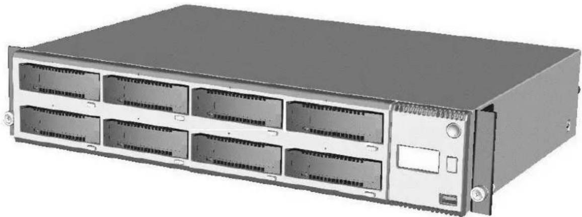
natural_image
Front view of a server rack unit with multiple drive bays and indicator lights (no visible text or labels)Introducon
This document provides informaon about installing, operang, troublesomeong, and servicing a vTanis product. This document is intended for system administrators and users who need informaon on the vTanis product.
Product warranty caution
The warranty for the vTanis shall not apply to failures of any unit when:
- The vTanis is repaired or modified by anyone other than the manufactures personnel or approved agent.
- The vTanis is physically abused or used in a manner that is inconsistent with the operang instrucons or product specicaon denied by the manufacturer.
- The vTanis fails because of accident, misuse, abuse, neglect, mishandling, misapplicaon, alteraon, faulty installaon, modicaon, or service by anyone other than the factory service center or its approved agent.
- The vTanis is repaired by anyone, including an approved agent, in a manner that is contrary to the maintenance or installaon instrucons supplied by the manufacturer.
- The manufacturer's serial number tag is removed.
- The vTanis is damaged because of improper packaging upon return.
In case of unauthorized repairs or modicaons, your warranty becomes immediately void.
Preface
About this manual
This manual provides informaon regarding the quick installaon and hardware features of the vTanis system. This document also describes how to use the storage management soware. Informaon contained in the manual has been reviewed for accuracy, but not for product warranty because of the various environment/OS/sengs. Informaon and specicaons will be changed without further noce.
This manual uses secon numbering for every topics being discussed for easy and convenient way of nding informaon in accordance with the user's needs. The following icons are being used for some details and informaon to be considered in going through with this manual:

Notes: These are notes that contain useful informaon and ps that the user must give aenon to in going through with the subsystem operaon.

Important: These are the Important informaon that the user must remember.

Warning: These are the warnings that the user must follow to avoid unnecessary errors and bodily injury during hardware and soware operation of the subsystem.

Cauon: These are the cauons that user must be aware to prevent damage to the equipment and its components.
Copyright
© Copyright 2010 by acdata. All rights reserved. This item and the informaon contained herein are the property of acdata. No part of this document may be reproduced, transmied, transcribed, stored in a retrieval system, or translated into any language or computer language in any form or by any means, electronic, mechanical, magnec, opcal, manual, or otherwise, without the express written consent of acdata.
Trademark Noces
acdata makes no representaon or warranes with respect to the contents of this document and specifically disclaims any implied warranes of merchantability or tness for any parcular purpose. Further, acdata reserves the right to revise this publicaon without obligaon of acdata to nofy any person or organizaon of such revision or changes.
vTanis userman 302708 Revision 12
Changes
The material in this document is for informaon only and is subject to change without noce.

NOTE: Some screen shots may dier from actual vTanis model.
Manual convenons

High voltage
Risk of electric shock
Do not remove top cover. No user-serviceable parts are inside.
Refer servicing to qualified service personnel.


Weight of vTanis = Risk of damage to devices
When placing a unit into or removing the unit from a rack:
Extend the rack's leveling jacks to the oor.
Ensure that the full weight of the rack rests on the leveling jacks.
Install stabilizing feet on the rack.

Stac sensitive = Risk of damage to devices
A discharge of stac electricity damages stac-sensitive devices or micro circuitry.
Proper packaging and grounding techniques are necessary precautions to prevent damage.

Venlaon – Place the product so that its locaon does not interfere with proper venlaon.
Heat – Place the product so that its locaon is away from external heat sources.
Power sources – Connect the product to a power source only of the type directed in the operang instrucons or as marked on the product.

vTanis userman 302708 Revision 12
Power cord protecon – Place the AC line cord so that it is not possible to be walked on or pinched by items placed upon or against it.
Object and liquid entry – Insure that objects do not fall and liquids are not spilled into the product's enclosure
Introduction 2
Product warranty caution....2
Preface....3
About this manual....3
Copyright....3
© Copyright 2010 by actidata. All rights reserved. This item and the information contained herein are the property of actidata. No part of this document may be reproduced, transmitted, transcribed, stored in a retrieval system, or translated into any language or computer language in any form or by any means, electronic, mechanical, magnetic, optical, manual, or otherwise, without the express written consent of actidata....3
Trademark Notices....3
Changes 4
Manual conventions....4
Product overview....9
Introduction to the vTanis....9
Front panel....14
LED behavior....16
Rear panel....18
Ethernet port LED behavior....20
Product installation....21
General installation considerations 21
Installing in a rack....26
Installing cables and connections....28
Powering up/down the unit....29
Product configuration....31
Product configuration process 31
vTanis userman 302708 Revision 12
Initial IP address assignment....31
Introduction to the vTanis RMI....32
Login in procedures....33
RMI Home page....36
Introduction to the vTanis OCP 40
OCP Display rotation....40
OCP Icons....42
OCP Navigation....42
iSCSI Connection....43
iSCSI Target set up....45
Administrator operations – The CONFIGURE tab....47
Setting the model name inquiry ....48
Special note: Tape library mode....50
Pre-formatting RDX® cartridges to tape library mode....50
Network settings....53
iSCSI Settings....57
User settings....61
Notification settings....65
Save/Restore configuration....68
Monitoring the unit cartridge and device identity/status – The MONITOR tab....70
Managing the unit – The MANAGE-tab....77
Performing Diagnostic operations - The DIAGNOSTICS tab....81
RDX® cartridges 92
Write-protecting cartridges....92
Inserting cartridges....94
Ejecting cartridges....94
Appendix....96
Product specification....96
vTanis userman 302708 Revision 12
Physical specification & Functional specification....96
Regulatory Requirements....98
CRU replacement....100
Power supply....100
Cooling fan....102
Base chassis....104
Packaging....106
Glossary....107
List of figures....110
List of tables 112
Product overview
Introducon to the vTanis
Overview and applicaons
The vTanis is a mul-cartridge data storage device designed to support up to 8 RDX ^ cartridges. It may be utilized as a table top unit or rack mounted in a 2U high space with the included rack mounng ears. The vTanis connects to the user's computer network via one or two (1 Gb/sec or 100 Mbit/sec) network ports using
iSCSI protocol. The vTanis unit is capable of operang in one of three administrator selected soware protocol modes designed to address a variety of operang environments. Future soware updates will allow the unit to be paroned into separate logical storage units facilitang the capability to simultaneously operate as two dierent logical units (which can operate in dierent soware protocol modes) while connected to dierent host systems/applicaons.
The vTanis unit features a local display panel (OCP) to display status and error informaon as well as a web based remote management interface (RMI) for remote monitoring. The RMI is also used by the system administrator to congregate the unit for operaon in their specific environment (initial set up) as well as provide the ability to remotely monitor and control unit operaons/status.
The vTanis is compatible with most operang systems and environments that support iSCSI network protocol. However, the vTanis requires either direct support from the operang system or a compatible backup applicaon to take full advantage of its many features.
vTanis product features
- Comparable with all capacities of RDX "data cartridges
- Provides up to 8 TB of nave data storage capacity using standard RDX ^® data cartridges
- Unit can be used as a table top or rack mounted with included rack mounng ears
• Supports up to 216 GB per hour data transfer rate (Future releases will enhance transfer rate)
vTanis userman 302708 Revision 12
- The vTanis displays cartridge status via the front panel display (OCP) with simple icons and provides more detailed informaon via the web based remote management interface (RMI).
- Front panel accessible USB 2.0 interface supports serviceability features and customized funcons (rmware upgrades, diagnosc log collecon, conguraon backup, etc.)
• Future soware releases will include supporting SNMP and SMI S management tools.
RDX ^® cartridge features
- Forward and backwards compatible with all RDX " docks
• High speed transfer rate for fast backups
- Superior vibraon control insures opmum data transfer speed
• High level of data reliability
- Error rate determined by HDD model in cartridge
- Ruggedized cartridge to protect from data loss due to normal user handling of cartridge
-
Cartridge materials engineered to protect from data loss due to ESD
-
Cartridge includes a fault indicator at the front of the cartridge to inform users when the cartridge is faulty.
- Cartridge includes a write protect slider to disable the write funcon.
- Cartridge includes a write protect switch to protect the cartridge from accidental overwrite of user data.
- Cartridge includes veng to enable cooling of the HDD.
- Cartridge includes gripping features for automaon.
- Cartridge provides a rear opening for use with a latch to control media removal.
- Cartridge prole is unsymmetrical (keyed) to aid incorrect inseron.
Operaon modes
The vTanis is capable of being congured during installaon by the administrator to present up to eight
RDX ^® cartridges to the host system (via the iSCSI Iniator) as one of three dierent conguraons of RDX ^® based storage devices. Depending upon the intended applicaon and data
management/backup applicaon in use the correct mode needs to be selected to support unit operaon. Please see the online vTanis soware-compatibility matrix for additional informaon or contact your reseller. Below is a brief descripon of each operang mode.
Seng of the modes is covered in chapter Seng the vTanis operaon mode, Page 47.
vTanis userman 302708 Revision 12
Mode 1- vTanis tape library (default seng):
The unit appears to the host applicaon as an 8 slot library (autoloader, media changer) containing one generic LTO tape drive. The applicaon controls which cartridge is “inserted” in the one available “tape drive”. This mode requires the use of a data management/ backup applicaons, which supports a library (media changer) containing one tape drive.
Note that the vTanis unit is emulang the LTO tape format to the host applicaon including the actual le format recorded on the RDX ^ cartridge. RDX ^ cartridges which are recorded in this mode are not write/read interchangeable with standard RDX ^ docks.
Use of this mode requires the administrator to pre-format the standard RDX ^® media to the tape format mode. The vTanis unit idenes the current cartridge format via the OCP and RMI interfaces.
Mode 2- vTanis JBOD:
The vTanis unit appears to the host operang system as 8 individual RDX ^® cartridge drives, each with their own drive leer.
Note that drive leers will only appear if an RDX ^® cartridge is inserted in an actual vTanis slot. Removal of media via cartridge eject will cause the drive leer to disappear. Reinseron of media will cause the drive leer to reappear.
This mode may be used with windows operang systems for standard disk operaons or with data management/backup applicaon designed to operate with individual RDX ^® storage units in a grouped conguraon.
Mode 3-vTanis disk library:
The unit appears to the host applicaon as an 8 slot library (autoloader, media changer) containing one
RDX ^® cartridge drive. The applicaon controls which cartridge is “inserted” in the one available drive. This mode requires the use of a data management/backup applicaons which supports a library (media changer) containing an RDX ^® drive.
For maximal supported operaon modes, see Table.
| IQN | # of data transfer elements | # of storage elements | # of export elements | # of move elements | |||
| iSCSI ID | Element type | Manufacturer name | Model Name |
| Mode 1 Removable tape library | |||||||
| SMC | acdata | vTanis T | 1 | 8 | 1 | 1 | |
| SSC | acdata | LTO | |||||
| Mode 2 Individual RDX ^ disk | |||||||
| SBD | acdata | RDX | NA | NA | NA | NA | |
| SBD | acdata | RDX | |||||
| SBD | acdata | RDX | |||||
| SBD | acdata | RDX | |||||
| SBD | acdata | RDX | |||||
| SBD | acdata | RDX | |||||
| SBD | acdata | RDX | |||||
| SBD | acdata | RDX | |||||
| Mode 3 Removable disk library | |||||||
| SMC | acdata | vTanis D | 1 | 8 | 1 | 1 | |
| SBD | acdata | RDX | |||||
Table 1 Operaon modes
Front panel
The front panel of the vTanis is constructed of durable plasc and is designed to provide both visual appeal and protecon from entry of dust/dirt. The eight spring-loaded cartridge bay doors prevent entry of dust when no cartridge is inserted, protect the unit from ESD, and control the cooling airrow through the device. The bezel surface may be cleaned with a water dampened lint free cloth.
Front panel layout

text_image
Diagram of a rack-mounted server with numbered components for identification and assembly reference.Figure 1 Front panel
| Number | Description |
| 1 | AC power button - So power switch with LED buon indicaon, green power on, amber standby (2 colors) and power icon graphic. |
| 2 | Operator control panel (OCP) - 64x128 graphics display with RGB back light. |
| 3 | OCP navigation button - display mode selector switch - used to play/pause informaon on the operator display. Also used to locally acknowledge/clear error messages. |
| 4 | USB 2.0 service port - used for special maintenance and conguraon funcons. |
| 5 | Cartridge eject button (8 places) - so eject buon with LED through buon indicaon (2 colors) - used to eject individual RDX* cartridges (when allowed by applicaon). |
| 6 | Cartridge identification label (on RDX* media)- May be used to identify individual cartridges |
| 7 | Emergency eject port (8 places) - used to manually eject individual cartridges when unit power is o or in error conditions. |
| 8 | Cartridge indicator - RDX* cartridge fault indicaon LED. |
| 9 | RDX* cartridge slot (8 places) - RDX* dock locaon that accepts any type of RDX* standard media. |
Table 2 Front panel
1. Power button
| LED state | Status | Description | |
 | O | No power | No AC Power is present at the vTanis rear connector. |
 | Blinking green | Unit staring | Unit is in the process of becoming ready for operaon. |
 | Steady green | Power on | Unit is ready for operaon. |
 | Blinking amber | Unit shung down | Unit is in the process of shung down. |
 | Steady amber | Standby | Unit is in standby, AC power is present. |
2. Cartridge eject button
| LED state | Status | Description | |
 | O | No power | No cartridge inserted |
 | Steady green | Ready | Cartridge is inserted and the RDX®is operang properly. |
 | Blinking green | Ejecng | Unit is ejecng the cartridge. |
 | Steady amber | Fault | Unit has detected a faultcondion. |
vTanis userman 302708 Revision 12
 | Blinking amber | Prevent | Prevent media removal set, host is accessing the cartridge. |
3. Cartridge indicator
| LED state | Status | Description | |
 | O | Not ready | Cartridge is not inserted properly or power is o. |
 | Steady green | Ready | Cartridge is ready. |
 | Blinking green | Acvity | Reading, wring or seeking acvity occurring |
 | Steady amber | Fault | Cartridge has a fault condion. |
Rear panel
The rear panel of the vTanis provides access to the power connector, Ethernet ports, power supply and cooling fan.
Rear panel layout
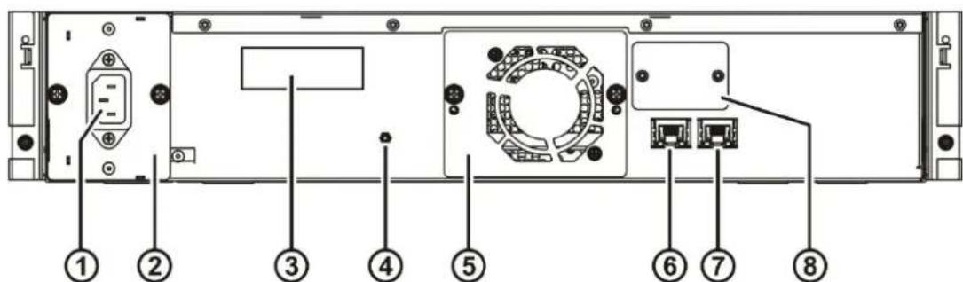
text_image
Diagram of a computer rack with numbered components, likely an Ethernet drive or memory unitFigure 2 Rear panel
| Number | Description |
| 1 | IEC Power connector (AC Power connection) |
| 2 | Power supply CRUfor replacement see chapter CRU replacement, Power supply, Page 100 of manual) |
| 3 | Product identification label |
| 4 | Hard reset port(reset system defaults, for more informaon see chapter Save/Restore configuration, Page 68 of manual) |
| 5 | Cooling Fan CRU(for replacement see chapter CRU replacement, Cooling fan, Page 102 of manual) |
| 6 | GigE iSCSI port 2 |
| 7 | GigE iSCSI port 1 |
| 8 | Removable back plate (for future options) |
Table 3 Rear panel
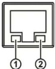
text_image
① ②Figure 3 Ethernet port
| Number | Description |
| 1 | Link/Activity LED:Blinking – indicates a link is established.O – indicates no link is established |
| 2 | Speed LED:Amber on – indicates a Gigabit conncon (1000 Mbps).Green on – indicates a 100-Mbps conncon.O – indicates a 10-Mbps conncon. |
Product installation
General installaon consideraons
This chapter provides instrucons for installing the vTanis.
Adhere strictly the following steps to install the vTanis product:
Selecng a locaon
Select a locaon that meets the following criteria:
| Criteria | Definition |
| Mounng orientaon | Horizontal only-either sing on a table top or mounted in a 19” equipment rack via the included rack mount ears. The vTanis weighs 15.7 lbs (7.1 kg) when fully populated with cartridges and must be placed on or mounted in a system capable of supporting this weight |
| Rack requirements | Standard EIA rack pitch-2U high space |
| Room temperatureOperangNon-operang | +10° - +40°C, gradient 10°C/hour-30° - +60°C, gradient 20°C/hour |
| Power source | 100-240 VAC input voltage50-60 Hz line frequency1.2-0.6 ALocate the vTanis within 6 . of an AC outlet.The AC power cord is the vTanis main AC disconnect device and must be |
vTanis userman 302708 Revision 12
| easily accessible at all mes. | |
| Air quality | Place the vTanis in an area with minimal sources of parculate generaon-excessive dust and debris can damage the system.Avoid locang the unit in areas near frequently used doors and walkways, smoke-llled rooms, or areas where it may easily be knocked over. |
| Humidity | |
| Operang | 20 – 80 % non-condensing |
| Non-operang | 20 – 90 % non-condensing |
| Recommended Clearance | Back:Front: Sides: |
For further informaon, see chapter Physical specification, Page 96.
Installaon precauons

Weight of vTanis
Risk of damage to devices
When placing a unit into or removing the unit from a rack:
Extend the rack's leveling jacks to the oor.
Ensure that the full weight of the rack rests on the leveling jacks.
Install stabilizing feet on the rack.

Stac sensitive
Risk of damage to devices
A discharge of stac electricity damages stac-sensitive devices or micro circuitry.
Proper packaging and grounding techniques are necessary precautions to prevent damage.

Do not expose the unit to moisture.
Use the unit on a rm level surface free from vibraon.
Do not place anything on top of the unit.
Unpacking the unit
Before unpacking the unit, clear a work surface to unpack the vTanis. Select either a table top locaon or if the unit is to be rack mounted an open rack locaon at least 2U spaces in vercal height.
Make sure that the intended operang locaon provides access to the network conncon(s) which will be used and an accessible AC power outlet within 6. of the unit.

If the temperature in the room where the unit will be installed varies by 15^ C ( 30^ F) from the room where the unit was stored, allow the unit to acclimate to the surrounding environment for at least 12 hours before unpacking it from the shipping container.
Unpacking the vTanis:
- Before opening and removing the vTanis from the box, inspect the container for shipping damage. If you noce any damage, report it to the shipping company immediately.
- Open the vTanis over pack box.
- Carefully remove the accessory tray and shipping materials from the top of the over pack box.
- Remove the inner box containing the vTanis.
- Open the vTanis box.
- Li the vTanis out of the carton and remove the bag from the unit.
- Save the packaging materials for future use.

Do not place the unit on either end or sides as this may damage the unit.
Idenfying the product components
Confirm that you received the following accessories in the over pack box (some items optional depending upon the user configuration):
• Power cord (region dependent)
• Applicaon soware CD
- Printed quick start guide
• vTanis document CD
- RDX ^8 cartridges
Confirm that you received the following in the vTanis box:
- vTanis unit
- Rack moung ears with included moung hardware
Required additional equipment for a successful installation:
vTanis userman 302708 Revision 12
- Ethernet cable(s)
- Screwdriver for installing rack mounng ears
- RDX ^* cartridges (if none ordered with unit)
- Applicaon soware (depending upon usage)

First, read the chapter Installation precautions, Page 23.
Skip to Chapter, Page 28; if the unit will not be rack mounted.
Required tools:
• #3 Phillips screwdriver
• T10 Torx screwdriver
Rack mounting the vTanis:
- Determine the locaon in the rack for the unit to be installed.
- Use a pencil to mark the locaon on each vercal rail in the rack.
- Install the rack ears of the unit using T10 Torx screwdrivers to ghten the Torx screws included in the rack mount kit.
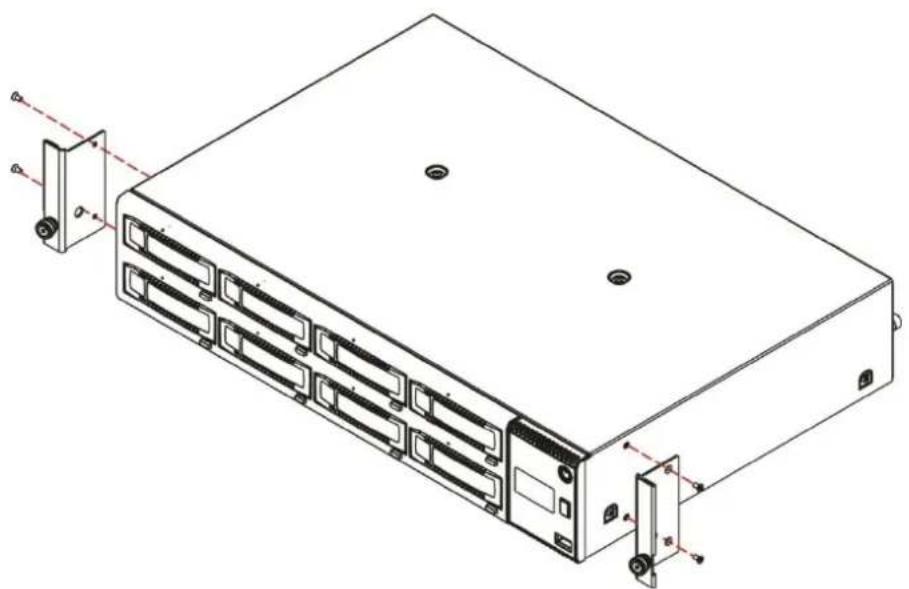
natural_image
Technical line drawing of a server rack unit with multiple drive bays and mounting ports (no text or symbols)Figure 4 Installing the rack ears
vTanis userman 302708 Revision 12
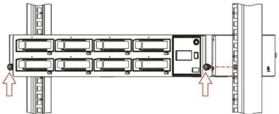
- Secure the unit to the rack using a #3 Phillips screwdriver or your ngers to ghten the two capve thumb screw(s) on each side of the unit.
natural_image
Diagram of a server rack with multiple units and connectors, showing front and side views (no text or labels)Figure 5 Securing the unit to the rack

High voltage
Risk of electric shock
Do not remove cover (or back). No user-serviceable parts are inside.
Refer servicing to qualified service personnel.

Usage of unapproved power cords
Risk of personal injury
Risk of damage to devices
Before connecng a power cord to the unit:
Ensure that the power cord meets individual country specific safety requirements.
Use a sucient conductor amp capacity to avoid overheang the unit.
The manufacturer disclaims all liability in the event a non-manufacturer approved power cord is used.
To connect the power cord to the unit:
- Plug the power cord into the power connector (AC connector) on the rear panel of the power supply;
see chapter Rear panel, Page 18. - Plug the power cord into the power outlet of the power supply.
To connect the network cable(s):
The conneccon to the Ethernet network is via an industry stand RJ45 copper interface on the rear panel of the unit; see chapter Rear panel, Page 18.
- Inset the Ethernet cable into the Ethernet port #1 of the unit. When the plug is in the full seated posion, a positive click should be heard.
Powering up/down the unit
The vTanis power buon indicator will be solid amber when AC power is present at the unit indicang the unit is in standby mode.
Before powering up the system insure that the network cable conncon to the host system is plugged into the vTanis Ethernet port 1. Port 1 is the right hand port when looking directly at the rear of the unit. A live network conncon is necessary to insure the unit either receives an IP address from the host network DHCP server or if DHCP services are unavailable automatically assigns a stac IP address.
Press and release the power buon on the front panel to power up the vTanis, during the power up process the indicator in the power buon will change from solid amber to ashing green indicang the unit is in the process of becoming ready. The vTanis unit will take approximately 120 seconds (2 minutes) to complete the power up boot sequence. During power up a progress bar will be displayed aer approximately 90 seconds providing boot progress indicaon for the remaining start up sequence operaons.

The vTanis will always start from standby mode if the last power shutdown of the unit was performed via a normal shutdown to standby mode (shutdown initiated by the pressing the power buon).
If however the unit was stopped or rebooted because of an AC power interrupon the unit will automatically boot backup to operaon mode without the necessity of a power buon push. This allows the vTanis to recover from power errors without additional operator intervenon.
Aer successful compleon of the power up sequence, the rear network interface(s) will be available for RMI (Remote Management Interface) and iSCSI communicaon (requires conguraon). The vTanis OCP (Operator Control Panel) will also become acve and will display the vTanis unit's IP address for ETH1, please take note of this IP address which will be used to both access the RMI and for the iSCSI communicaon portal as well.
The OCP may be set to automacally rotate through the individual status screens by pushing and holding the display navigaon buon for three seconds then releasing the buon (long push). If it is desired to pause the display at any me during this rotaon sequence a “long push” will enter pause mode (long push to pause/long push to play). When the OCP display is paused the status screens may be stepped through by pushing and releasing (without holding) the OCP buon (short push).
Pending errors will be indicated by the OCP backlight blinking amber accompanied by the display of a text based error message. Error messages may be cleared from the OCP display by acknowledging the message via a push of the display navigaon buon. Pending error messages may also alternately
vTanis userman 302708 Revision 12
be cleared by a user logged in over the RMI by acknowledging the error within the system status informaon block of the RMI interface.
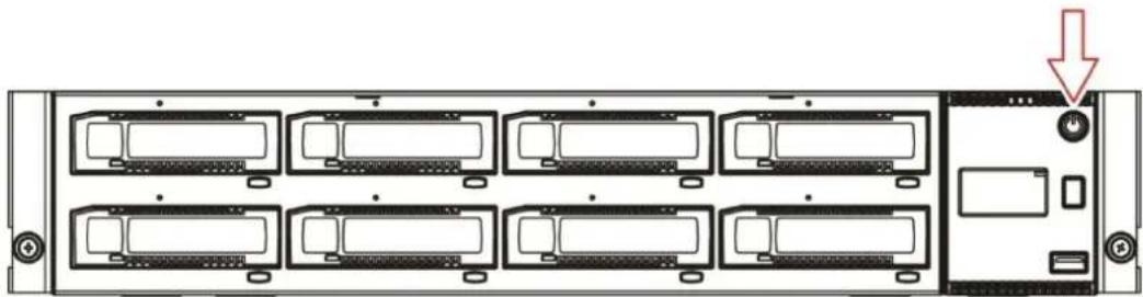
To power down the unit press and hold the power buon for 4 seconds and release. The power indicator will ash amber indicang the unit is in the process of powering down. Once the unit has completed the power shutdown sequence the power indicator will be solid amber indicang the unit is in standby mode.

Do not insert RDX ^® cartridges until the preliminary vTanis conguraon process is completed!
natural_image
Front view of a rack-mounted server unit with multiple drive bays and a highlighted switch (no text or labels visible)Figure 6 Power up/down the unit
Product configuration
Product conguraon process
Once the vTanis unit has been powered up the unit must be congured to the customers desired network sengs and operaonal mode (based on target applicaon soware). In order for the unit to be congured to the customer's network it must be accessed via the built in RMI (Remote Management Interface). The RMI is accessed over the customer's local IP network using an internet browser applicaon.
The vTanis is compatible with the following internet browser applicaons:
- Mozilla Firefox
- Internet Explorer
- Google Chrome
- Safari
- Opera
Initial IP address assignment
The vTanis comes congured to communicate over Ethernet port 1 (Ethernet port 2 is disabled) and will search for an IP address as follows:
- Aer the unit completes the power up sequence it will search the user's local network for a DHCP server.
- If a DHCP server is found it will receive the assigned IP address from the local DHCP server and use this address for operaons, the DHCP address will appear on the units OCP.
- If aer 60 seconds no DHCP server is found/DHCP IP address assigned the unit will use the APIPA protocol to assign a stac IP address, the assigned stac IP address will appear on the units OCP.
- Once an IP address is assigned the unit may be reconfigured to a new stac IP address or redirected to a DHCP server by the system administrator logging into the unit over the RMI interface.
vTanis userman 302708 Revision 12
Introducon to the vTanis RMI
The vTanis unit uses the web based RMI to allow the administrator to conjure and monitor the unit. The vTanis IP address may be viewed over the OCP and is displayed between the cartridge monitoring screens for slot 8 and slot 1 (#1 out of 9 screens in connuous rotaon) Once the vTanis units IP address is known browse to the unit with your web browser applicaon (by entering the vTanis RMI IP address in your browsers address bar). You will have to enter “hp://XXX.XXX.XXX.XX/” where the “X”s indicates the actual IP address. The IP address protocol does not require leading zeros so hp://172.16.1.43/ is a valid IP address.
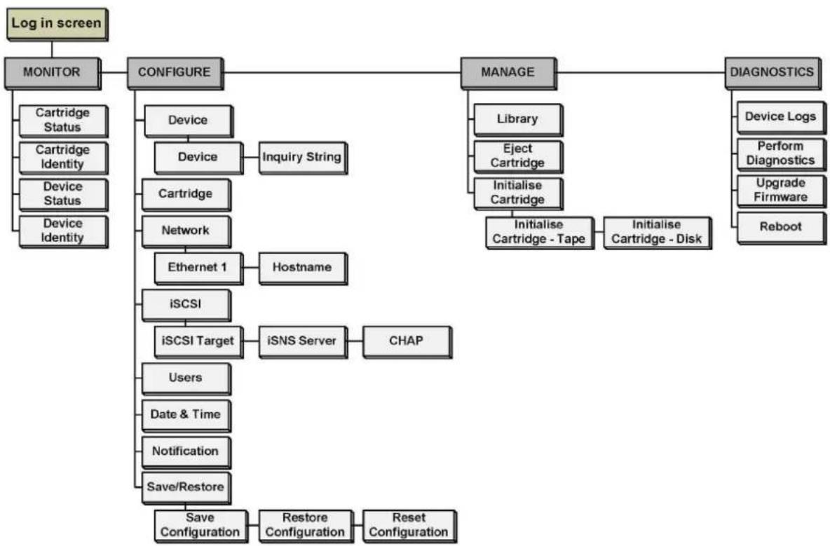
The overall menu structure of the vTanis RMI is shown in the chart below, depending upon the class of user (Administrator, User, or Service) login some menu funcons may not be available. For instance if logged into the RMI interface with User level credenals the menus for “CONFIGURE”, “MANAGE” and “DIAGNOSTICS” will neither be visible nor accessible by the user.
RMI ow chart
flowchart
graph TD
    A["Log in screen"] --> B["MONITOR"]
    B --> C["CONFIGURE"]
    C --> D["MANAGE"]
    D --> E["DIAGNOSTICS"]
    C --> F["Device"]
    F --> G["Device"]
    G --> H["Inquiry String"]
    C --> I["Cartridge"]
    I --> J["Network"]
    J --> K["Ethernet 1"]
    K --> L["Hostname"]
    C --> M["iSCSI"]
    M --> N["iSCSI Target"]
    N --> O["iSNS Server"]
    O --> P["CHAP"]
    C --> Q["Users"]
    Q --> R["Date & Time"]
    R --> S["Notification"]
    S --> T["Save/Restore"]
    T --> U["Save Configuration"]
    U --> V["Restore Configuration"]
    V --> W["Reset Configuration"]
    D --> X["Library"]
    D --> Y["Eject Cartridge"]
    D --> Z["Initialise Cartridge"]
    Z --> AA["Initialise Cartridge - Tape"]
    Z --> AB["Initialise Cartridge - Disk"]
    E --> AC["Device Logs"]
    E --> AD["Perform Diagnostics"]
    E --> AE["Upgrade Firmware"]
    E --> AF["Reboot"]
Figure 7 RMI ow chart
vTanis userman 302708 Revision 12
Login in procedures
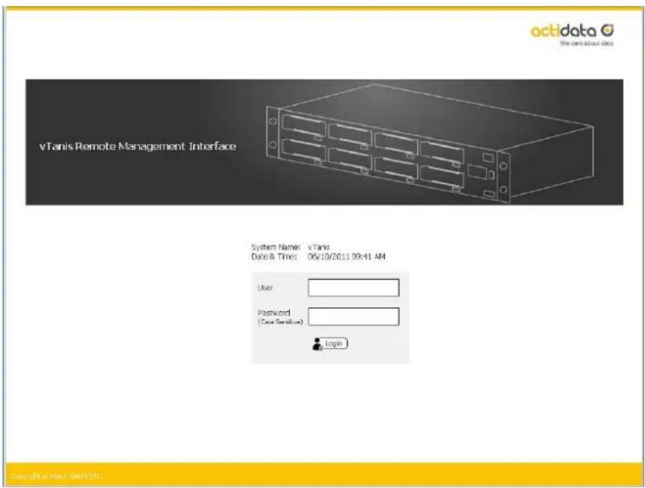
In order to access the vTanis remote management interface (RMI) it is necessary to rst log into the RMI interface. Using the IP address visible over the unit's front panel OCP enter the IP address into your browsers address bar and navigate to the vTanis log in page. The RMI opening log in page is visible below.
Log in screen page
text_image
octidata We can about data vTanis Remote Management Interface System Name: vTanis Date & Time: 06/10/2011 09:41 AM User Password (Case Sensible) Login Copyright © October 2011Figure 8 RMI log in screen page
text_image
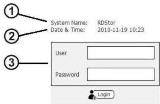
① System Name: RDStor Date & Time: 2010-11-19 10:23 ② User Password ③ LoginvTanis userman 302708 Revision 12
Figure 9 RMI log in detail
① System Name:
Displays the name currently assigned to the vTanis unit, the factory default seng is "vTanis". This eld may be changed by the administrator under the "CONFIGURE/Device" "System name" tab. This eld may only consist of alphanumeric characters.
• ② Date & Time:
The current system date and me displayed in MM/DD/YY and 12 h me with AM/PM indicacn format. This eld may be changed by the administrator under the “CONFIGURE/Date & Time” “Date” and “Time” tab. These elds may only consist of alphanumeric characters.
• ③ User name & Password authentication:
This is the locaon were the user enters in their specic log in informaon. Access to RMI menus is granted by log in levels as follows:
Following are default account names and passwords:
| User Level | Username | Password |
| User | user | std001 |
| Administrator | administrator | adm001 |
| Service | service | ser001 |
The user name and the password eld are both case sensitive. Both elds are limited to 255 alphanumeric characters. New user accounts may be created (user name, user level, nocaaon email address and password) by the administrator under the "CONFIGURE/Users" tab.
RMI features:
- The RMI has an idened class of users.
- The RMI grants access or ability to perform operaons based upon user rights.
- The RMI grants the administrator and service levels full access to device set up, diagnoses, and logging.
vTanis userman 302708 Revision 12
- The user level only provides the ability of the user to monitor device and cartridge status.
vTanis user levels (Access levels)
| User Level | MONITOR | CONFIGURE | MANAGE | DIAGNOSTICS |
| Administrator | ● | ● | ● | ● |
| Service | ● | ● | ● | ● |
| User | ● |
RMI Home page
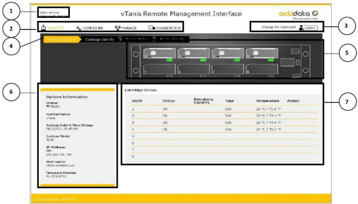
Upon a successful log in into the vTanis RMI all users will be directed to the vTanis home page which is “MONITOR/Cartridge Status”. An overview of the main graphic elements is displayed below. The main navigaon is performed via selecon (via mouse click) of the main topic bar (element 2 in the RMI home page chart) and then selecon of the associated sub topics (element 4) in the chart. Key anchor elements are the acve system graphic (element 5) and the system informaon block (element 6) which are visible in all RMI screens/modes.
RMI Home page
text_image
vTanis Remote Management Interface User: service VTanis Remote Security MONITOR CONFIGURE MANAGE DIAGNOSTICS Change My Password Logout Cartridge Identity Cartridge Status Cartridge Status Status: READY System Names: vTanis System Date & Time Stamp: 06/10/2011 09:45 AM System Mode: DCO IP-Address: ath1 192,168,150,150 Host names: vTanis.adtdata.com Firmware Version: R1.09 0x4701 3 5 7 6Figure 10 RMI home page
| Number | Description |
| 1 | Logged in user / Log in user level:This eld is visible in all screens; shows the current user account name and user credenal level |
vTanis userman 302708 Revision 12
| Number | Description |
| 2 | Main topic bar (selected in red):This eld is visible in all screens; the four main RMI menus are accessed from this set of choices by selecng with a point and click. Operators with user level credenals will not have access to the “CONFIGURE” and “DIAGNOSTIC” menus. |
| 3 | Log out button / Change password:This eld is visible in all screens; the user may change their password (pop up dialog) or logout via point and click. |
| 4 | Sub topic bar (selected in red):This eld is visible in all screens; the content of the sub topic bar changes with the main topic selecon. |
| 5 | Active system graphic (mouse over for additional detail info):This eld is visible in all screens; the status of individual cartridge slots may be veried by the graphics. The system graphic and the OCP use the same icon indicaons; additional informaon is available via mouse over of each cartridge graphic (for slots which have cartridges inserted). |
| 6 | System information block, global information/alerts:This eld is visible in all screens; the system informaon block covers key global parameters related to overall system status and idencaon. If the system has pending errors they will be indicated by the status icon and additional informaon will be available under the associated informaon buon. |
| 7 | Sub topic details:The subtopic details change with the main topic selecon. |
RMI System informaon block
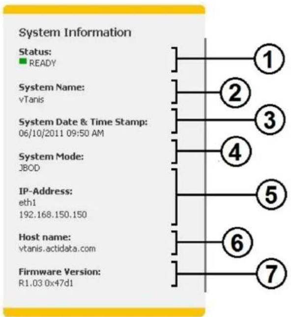
The system informaon block provides an overview of global system informaon, the elds are summarized below.
flowchart
graph TD
    A["1"] --> B["2"]
    B --> C["3"]
    C --> D["4"]
    D --> E["5"]
    E --> F["6"]
    F --> G["7"]
    style A fill:#fff,stroke:#000
    style B fill:#fff,stroke:#000
    style C fill:#fff,stroke:#000
    style D fill:#fff,stroke:#000
    style E fill:#fff,stroke:#000
    style F fill:#fff,stroke:#000
    style G fill:#fff,stroke:#000
Figure 11 RMI system informaon
| Number | Description |
| 1 | Global system status:This graphic indicates the system status by color; green indicates good status, yellow indicates warning status, red indicates crical error status- if the system is currently in either warning or crical error status mode additional informaon will be available via an informaon buon icon located next to the status indicaon. |
| 2 | System name:The system name appears at log in and also with remote email alerts and may be assigned by the administrator. |
vTanis userman 302708 Revision 12
| Number | Description |
| 3 | Date/Time:The system date and me is displayed here and is used for logging and remote nocaoon me stamps. |
| 4 | Current System mode:This eld displays the current vTanis system access mode. |
| 5 | Ethernet address for port 1 & 2:The current port IP address is displayed in this eld. |
| 6 | Host name:The host name eld displays the host name and domain name together. This naming will be associated with the IP address as the DNS name as well (may search for the host name or the physical IP address in the iSCSI driver. |
| 7 | Firmware revision level:The current unit rmware level and rmware image check sum are displayed in this eld. |
Introduction to the vTanis OCP
The vTanis unit includes an LCD based display located on the right side of the unit's front bezel. Highlights of the OCP are:
- 64 dot high by 128 dot width graphics display
- Displays both text and icon based informaon
- Uses RGB (red/green/blue) capable backlight
• Under normal conditions backlight uses white light
- A ashing amber backlight is used to alert the user to error conditions in order to clear the ashing indicaon the error must be acknowledged via either an display navigaon buon push on the unit front panel or acknowledged through the remote RMI console by reading the error message in the system informaon block.
- Alternately any pending error condion will wake the backlight to a ashing amber error condion with text display of the error message
OCP Display rotaon
Once the vTanis unit completes the power up boot sequence the OCP will become acve. The OCP will display screen one, screen one is a unique amongst the other OCP screens and idenes the unit's IQN name, current IP address / status of Ethernet ports 1 and 2 as well as the unit current rmware revision level.
The normal display mode rotates through nine screens, screen one is followed by eight individual screens indicang slot status (if a cartridge is currently installed or not and some format parameters of the current cartridge).
Aer initial power up the unit will hold on screen one, once the addressing informaon is recovered from this screen the OCP may be set to automacally rotate through all screens by pushing and holding the OCP navigaon buon for a few seconds (long push) then releasing the buon.
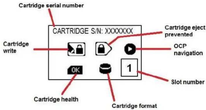
The general layout of the cartridge status screen is shown in the gure below:
vTanis userman 302708 Revision 12
text_image
Cartridge serial number CARTRIDGE S/N: XXXXXXX Cartridge write Cartridge health Cartridge format 1 OCP navigation Slot number Cartridge eject preventedFigure 12 OCP cartridge status
OCP Icons
The vTanis makes use of graphic icons to indicate some conditions to the user. These icons are used both on the local OCP display and over the RMI display in the acve system graphic. The vTanis icons in use are shown in the gure below.
| Group | Icon | Meaning |
| OCP Navigaon |  | Step to next bay/cartridge info |
 | Pause at current screen | |
| Cartridge Format |  | Disk LUN mode or disk format cartridge |
 | Tape format on cartridge (tape emulaon) | |
| Cartridge Status |  | Write to cartridge prevented (Write Protect) |
 | Eject of cartridge prevented (Prevent Set) | |
| Cartridge Metrics (RMI) | [0x=1] | Temperature |
| [4x=1] | Number of inseron cycles | |
| [0x=1] | Accumulated operaonal me | |
| Cartridge Status |  | Cartridge status not OK (only for OCP) |
 | Cartridge status OK (only for OCP) | |
| [###] | No cartridge inserted (only for OCP) |
OCP Navigaon
vTanis userman 302708 Revision 12
The vTanis OCP supports the viewing opon of pausing the display at any individual screen or if the display is already paused manually stepping through screens. The OCP navigaon operates as follows:
- To pause the (currently cycling) display press and hold the OCP navigaon buon for approximately 3 seconds, the OCP will change to pause mode indicated by the OCP navigaon icon changing to the step icon.
- To step the OCP display to the next screen (when the OCP is in pause mode) press and release (short buon press) the OCP navigaon buon. You may repeat this operaon to step through the OCP screen rotaon until you reach the desired screen.
- To resume the normal OCP automac cycling press and hold the OCP navigaon buon for approximately three seconds, the OCP navigaon will resume the auto rotaon mode indicated by the OCP icon changing to the pause icon.
- When in display rotaon the vTanis OCP automacally cycles through the nine informaon display screens unless there is a pending error condion. Any pending error will cause a local alertng condion (indicated by text message in display/amber backlight ash).
- If there is a current error the error message may be acknowledged/cleared by pushing and releasing the OCP navigaon buon. Errors may also be cleared remotely over the RMI interface.
- Mulple errors will queue so it may be necessary to push the OCP buon mulple mes to clear errors, with each push any pending error messaging will be updated to indicate the condition which triggered the error.
iSCSI Connecon
In order for data transfer to occur over the network conneccon it is necessary to install an iSCSI Initiator on the host computer system. The following direcons pertain to the Microso operang systems.
The Microso iSCSI Iniator comes included with Windows 2008, Windows 2008 R2 and Windows 7, for other Microso operang systems you may search the Microso Web site for the Microso iSCSI Iniator.
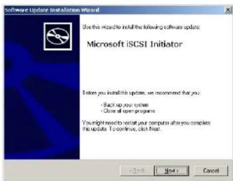
Download the iSCSI applicaon and install per the instrucons below.
vTanis userman 302708 Revision 12
text_image
Software Update Installation Wizard Use the Wizard to install the following software update: Microsoft iSCSI Initiator Before you install this update, we recommend that you: - Back up your system - Close all open programs You might need to restart your computer after you complete this update. To continue, click next. < Back Next > Cancel-
Download the iSCSI soware installaon package from the Microso web site.
-
Start the Microso iSCSI installaon wizard and click next
text_image
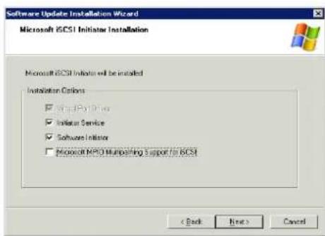
Software Update Installation Wizard Microsoft iGCSI Initiator Installation Microsoft iGCSI Initiator will be installed Installation Options ✓ Initiate PPO Drive ✓ Initiate Service ✓ Software Initiator ✓ Microsoft PPO Multipathing Support for iGCSI < Back Next > Cancel- Select "Iniator Service" and Soware Iniator, click next.
DO NOT install "Microso MPIO Mulpathing Support for iSCSI".
text_image
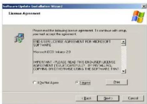
Software Update (Installation Wizard) License Agreement Please react the following license agreement. To continue with setup, you must accept the agreement. END-USER LICENSE AGREEMENT FOR MICROSOFT SOFTWARE. Microsoft BSCI Inhibitor 2.0 IMPORTANT - PLEASE READ THIS END-USER LICENSE AGREEMENT (FULL) CAREFULLY. BY INSTALLING. COPYING OR OTHERWISE USING THE SOFTWARE THAT I Do Not Agree Do not Finish < Back Next > Cancel- Select "I Agree" and then "Next".
text_image
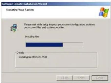
Software Update Installation Wizard Updating Your System Please wait while setup inspects your current configuration, achieves your current files and updates your files. Installing Files Details Installing File MSISCSI.PDB Click Finish Cancel- Files will install then choose "Finish".
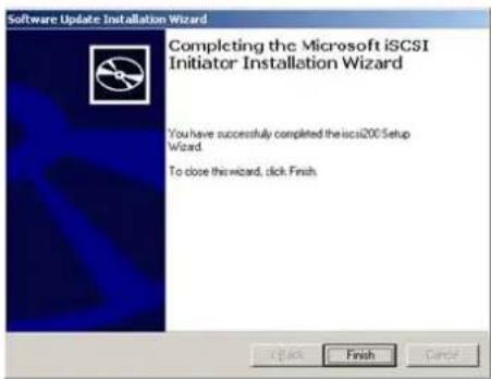
text_image
Software Update Installation Wizard Completing the Microsoft iSCSI Initiator Installation Wizard You have successfully completed the iscsi200 Setup Wizard To close this wizard, click Finish- Click "Finish".
iSCSI Target set up
Once the iSCSI Iniator is installed the next operaon is to connect the vTanis unit to the operang system by identifying it as an iSCSI Target. The following procedure is used to set up the iSCSI Target.
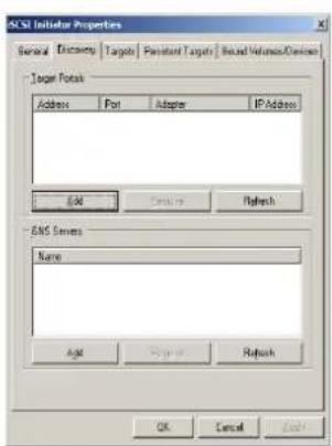
text_image
ACSI Initial Properties General Discovery Targets Persistent Targets Second Volume/Device Tag Port Address Port Adapter IP Address EAT Create Refresh EMS Server Name AAT Update Refresh OK Cancel Finish-
Open Microso iSCSI Iniator
-
On the "Discovery" tab and under "Target Portals" click "Add"
vTanis userman 302708 Revision 12
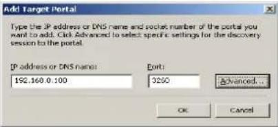 | 3. Type the current IP address (for DNS or stac IP address) or the DNS name (displayed as “Host name” in the system informaon block of the RMI) of the vTanis unit then click “Advanced”. | |
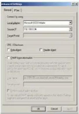 | 4. On the Advanced Sengs General tab choose5. Local adapter – select Microso iSCSI Iniator.6. Source IP – select the appropriate device IP address.7. Click “OK”. | |
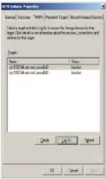 | 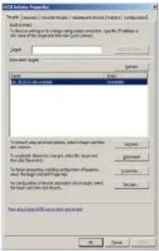 | 8. The iqn for the vTanis unit should be shown under available targets.9. Highlight the vTanis iqn by clicking on it.10. Depending upon which version of MS Iniator in use you may need to either click “Log On” or “Connect”The vTanis iqn should now change to connected; the vTanis is now connected via iSCSI.Proceed with applicaon soware installaon |
Seng the vTanis operaon mode
The vTanis comes congured from the factory preset for tape library emulaon, if you have completed installaon of the iSCSI initiator and connected to the unit via the targets tab and you are planning on using tape applicaon backup soware you may now install your soware. If you are planning on using the vTanis in a mode other than tape emulaon eachment you need to change the operaon mode of the vTanis via the RMI interface.
The operaon mode selected will apply to the enre (all eight slots of the) vTanis unit.
To accomplish the operaon mode selecon you must be logged into the RMI with administrator privileges.
You navigate to the "CONFIGURE/Device" tab. Under this page there are two sub tabs, "Device" and "Inquiry String". The "Device" tab contains two selector elds.
The rst eld is "System Mode" which uses a dropdown box to allow the administrator to select the operaon mode of the device. The operaon mode choices are 'Tape Library', "Disk Library", and "JBOD". The vTanis system comes precongured from the factory as default in the "Tape Library" operaon mode.
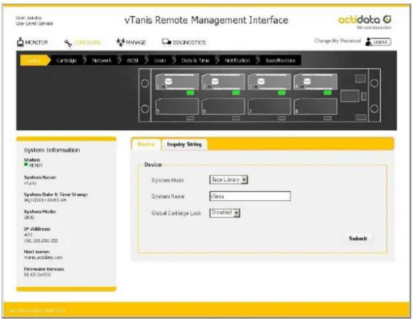
text_image
vTanis Remote Management Interface Monitor CANADA MANAGE DIAGNOSTICS Change My Password LOGO Cartridge Network BCSI User Data & Time Notification Save/Neustone System Information Status: READY System Name: vTanis System Date & Time Stamp 06/20/2011 06:43 AM System Mode: SPG IP Address: xh1 192.169.050.250 Next name: www.acdata.com Hardware Version: R1.03.0x4703 Device Inquiry String Device System Mode Tape Library System Name Tena Global Cartedge Lack Disabled SubmitFigure 13 RMI congure device
vTanis userman 302708 Revision 12
To change the vTanis conguraon the desired operaon mode must be selected from the "System Mode" box. Then the "Submit" buon must be selected by the administrator for the changes to be applied, a conrmaon dialog will appear as follows:
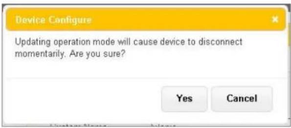
text_image
Device Configure Updating operation mode will cause device to disconnect momentarily. Are you sure? Yes Cancel
Unless the correct operaon mode is selected for your parcular environment data access to the vTanis may become unavailable aer a mode sengs change.
Also it may be necessary to delete and reconnect the ISCSI conncon then reboot the computer system hosng the data applicaon which will control the vTanis unit to insure proper detecon of the vTanis system.
Seng the model name inquiry
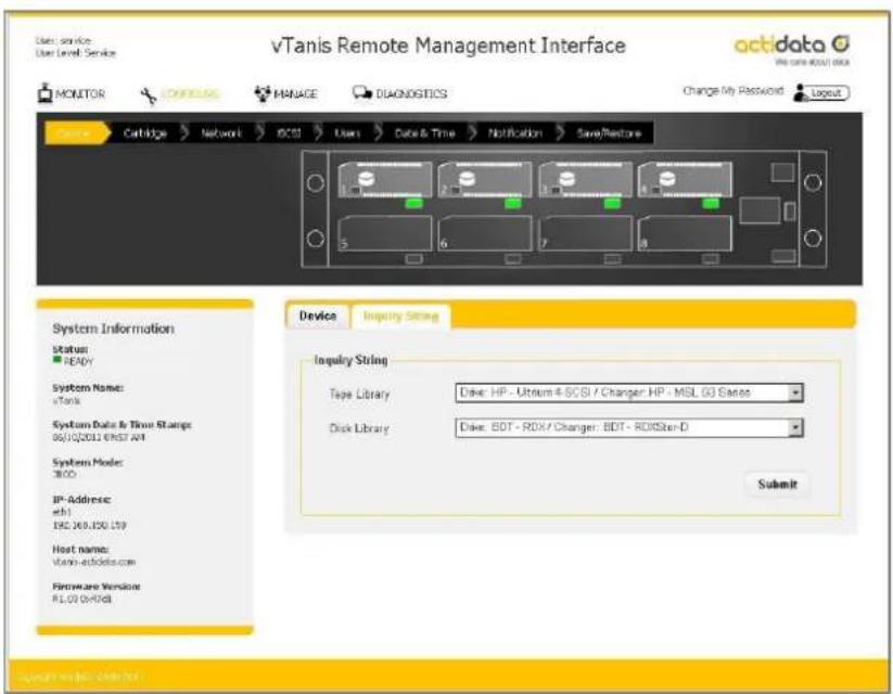
Under the "CONFIGURE/Device" tab there is an "Inquiry String" tab. Here the administrator may set the desired inquiry string data.
The vTanis comes precongured for usage with most backup applicaons. Selecng a dierent inquiry string may cause the vTanis to not be recognized by the backup applicaon.
text_image
vTanis Remote Management Interface actidata File name: vTanis remote MONITOR CHANGE MANAGE DIAGNOSTICS Change My Password Login Database Cartridge Network DC30 Users Date & Time Notification SaveRestore System Information Status: READY System Name: vTanis System Data & Time Stamps: 06/10/2021 EPST-AT System Mode: 3800 IP-Address: eH1 ESC 269.150.159 Host name: vTanis-echdata.com Hardware Version: RLOO 0x4708 Device Inquiry String Inquiry String Tape Library Dave: HP - Uttaum 4-SCG / Changer: HP - MSL G3 Series Disk Library Dave: BDT - RDX / Changer: BDT - RDXSten-D SubmitFigure 14 RMI congure inquiry string
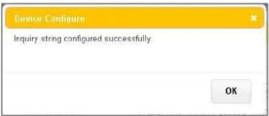
In order for the selected inquiry string to be applied the user must choose the desired inquiry string then click on the "Submit" buon, a conrmaon dialog will appear as follows:
text_image
Device Configure Inquiry string configured successfully OKvTanis userman 302708 Revision 12
Special note: Tape library mode
The vTanis tape library mode allows RDX ^® cartridges to be recorded to sequentially like traditional backup tape devices. In order to make use of this mode the standard RDX ^® direct access format and le system is moved to a small paron on the RDX ^® cartridge and a large hidden paron is created for recording the tape format emulaon. When an RDX ^® cartridge is formed as a tape cartridge the small paron remains so that standard RDX ^® systems can recognize the cartridge has been formed to emulate tape. Please do not store any user data les in the visible paron.

Usage of the vTanis in tape library mode requires pre-formang of the RDX ^* cartridges into the tape format mode before they may be used with tape backup applicaons.
RDX ^3 cartridges which have been formed into tape mode will not data interchange with single RDX ^3 docks (single RDX ^3 docks will be incapable of reading vTanis tape mode cartridges).
Pre-formang RDX ^® cartridges to tape library mode
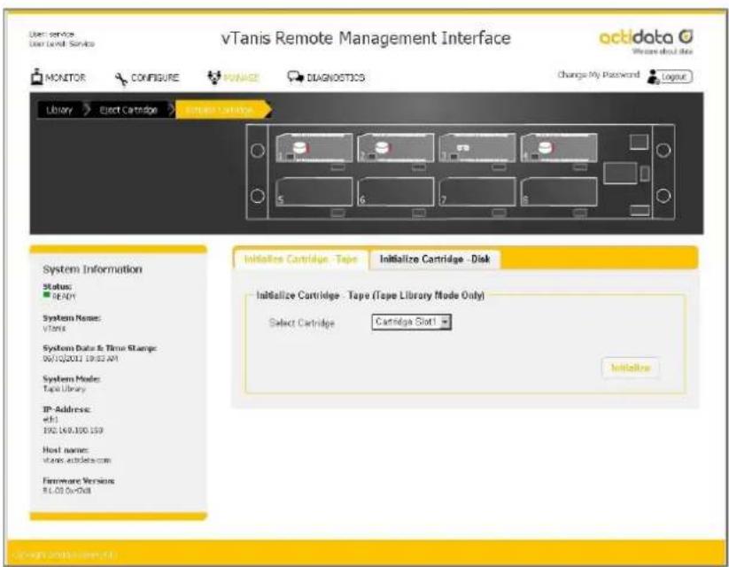
The vTanis supports a funcon to prepare standard RDX ^® cartridges for tape emulaon use. This formang process is called “Initialize Cartridge”.
To convert RDX ^® cartridges into tape emulaon format the vTanis system must be set to the "Tape Library" mode in the "CONFIGURE/Device" tab (default seng from the factory). The administrator then selects the "MANAGE/Initialize Cartridge - Tape" tab and selects which cartridge(s) will be formed to the tape emulaon format.
text_image
vTanis Remote Management Interface Monitor CONFIGURE PANAGE DIAGNOSTICS Change My Password Logout Library Elect Cartridge Import Cartridge System Information Status: READY System Name: vTanis System Data & Time Stamp: 06/10/2011 19:02 AM System Mode: Tape Library IP Address: e#.1 192.140.100.159 Host name: vlanx.ac.uk@com Firmware Version: R.L.O.S.Dw788 Initiate Cartridge - Tape Initialize Cartridge - Disk Initialize Cartridge - Tape (Tape Library Mode Only) Select Cartridge Cartridge Slot1 InitiateFigure 15 RMI inialize cartridge
The vTanis will only display cartridge posions with actual cartridges inserted in the unit; an aempt to format a cartridge which has the write-protect switch set will result in "Cartridge in Slot X Acvated Failed".

Initializing the RDX ^ cartridge into tape mode or from tape format back to disk format destroys any previously written user data on the cartridge (the RDX ^ cartridge will contain no user data - be blank).
Re-formang tape format RDX ^® cartridges back to standard RDX ^® disk
To convert previously tape formaed RDX "cartridges back into standard RDX" disk format the vTanis system must be congured as a tape library. The administrator then selects the "MANAGE/Initialize Cartridge - Disk" tab and selects which cartridge(s) will be formaed back to standard disk format.
Conversaon of cartridges from tape emulaon back to disk format is done using the FAT32 format. If the user desires to place a dierent le system format on the cartridge they may choose to use windows (right click on cartridge icon in windows desktop) to format with NTFS or other format opons.
vTanis userman 302708 Revision 12
Labeling tape format cartridges (oponal)
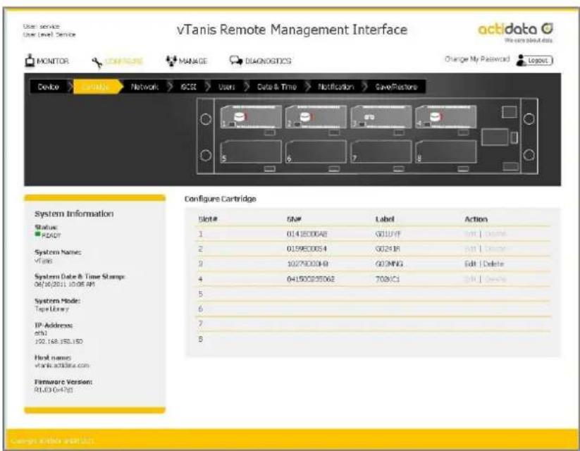
If the vTanis system will be operated as a tape library and the administrator has already created tape format cartridges they may oponally decide to assign custom labels. Custom RDX ^* cartridge labeling may be created under the “CONFIGURE/Cartridge” menu.
To alter the cartridge label which will appear as the tape inventory tag for the cartridge the administrator may select the cartridge and then choose the edit buon. There will be a pop up dialogue where you may enter a custom label up to 25 characters long.
This custom label will both be displayed in the vTanis RMI and shown by the volume label informaon returned by the vTanis to the tape backup applicaon. It is strongly recommended that if the administrator intends to use custom labels they rst assign these labels before the RDX ^® media is added to the tape applicaon media set.
Also, the custom assigned label will only be available in the tape emulaon mode. The cartridge label will always appear as the factory assigned volume label when the cartridge is used in JBOD mode (even if it remains tape emulaon format). The custom label may be deleted at any me and the cartridge will revert back to the factory assigned cartridge label.
text_image
vTanis Remote Management Interface Monitor CONTENTS MANAGE DIAGNOSTICS Change My Password Logot Device Exchange Network GCSE Users Data & Time Notification Save/Factor Configure Cartridge Slot# SN# Label Action 1 0143000A8 G01UVP Add | Change 2 0159E0064 G02416 Add | Change 3 1027902049 G03MNG Edit | Delete 4 041500293062 708XC1 Add | Change 5 System Mode: Tape Library 6 IP Address: e01 100.168.150.150 7 Host name: vTanis.adidas.com Firmware Version: R1.03 0-4765 Cancel Active AvailableFigure 16 RMI congure cartridge
vTanis userman 302708 Revision 12
Network sengs
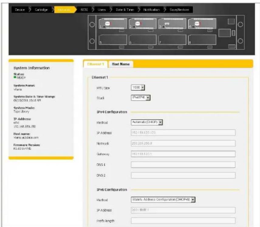
To establish network sengs for the vTanis unit the administrator may select the "CONFIGURE/Network" tab. The following sengs are located under the "Network" tab:
text_image
Device > Cartridge > MS-20 > BIOS > Users > Date & Time > Notification > Save/Restore System Information Status: READY System Name: Windows System Date & Time Storage: 06/10/2011.10:18 AM System Mads: Tape Library IP Address: eNf 192.168.15%150 Host name: vlanis-acidate.com Firmware Version: R1.02.0x7d$ Ethernet 1 Host Name Ethernet 1 MTU Size 1500 Stack IPv4IPv6 IPv4 Configuration Method Automatic(DHCP) IP Address 162.18x123.125 Network 253.255.255.8 Gateway 162.18x123.1 DNS 1 DNS 2 IPv6 Configuration Method Stateful Address Configuration(DHCP\v6) IP Address 2001 mmr.1 Prefix lengthFigure 17 RMI congure Ethernet
Ethernet1:
This seng allows the administrator to either "Acvate" or "Deacvate" the network ports on the rear of the unit. Ethernet port #1 is the rightmost port when looking directly at the rear of the unit.
MTU Size:
The maximum transmission unit size controls the maximum data packet size over the network. 1,500 is the default seng.
Stack:
The stack selects the version of the Internet protocol the vTanis will use when communicating on the network. Selecon opons are IPV4, IPV6, or IPV4/IPv6. The default seng of the vTanis unit is IPv4.
Method:
vTanis userman 302708 Revision 12
The method will select the IP addressing mode the vTanis will use. The two opons are DHCP or manual. The vTanis default conguraon is DHCP.
- DHCP - this means the vTanis will seek out the DHCP-sever on your network and automacally obtain an IP address from the server each me it powers up.
- Manual - the IP address set in this page will be the IP address the unit will use each me it powers up.
IP Address:
If the method is set to Manual this is the IP address that the vTanis will present over the selected port.
Netmask:
If the vTanis is congured to use DHCP the net mask will be issued from the DHCP server. If you are using a stac IP address (manual method) enter the IP mask in this box.
Gateway:
Enter the IP address of the network gateway.
DNS 1:
This is the IP address of your name server (DNS server). A DNS server allows the vTanis to communicate with other network clients via their host name. If you have a DNS Server on your network, enter the IP address in this eld.
DNS 2:
This is the alternate IP address of your name server (DNS server). A DNS server allows the vTanis to communicate with other network clients via their host name. If you have a DNS server on your network, enter the IP address in this eld.
In order for any changes on this page to be applied the "Submit" button must be set.
text_image
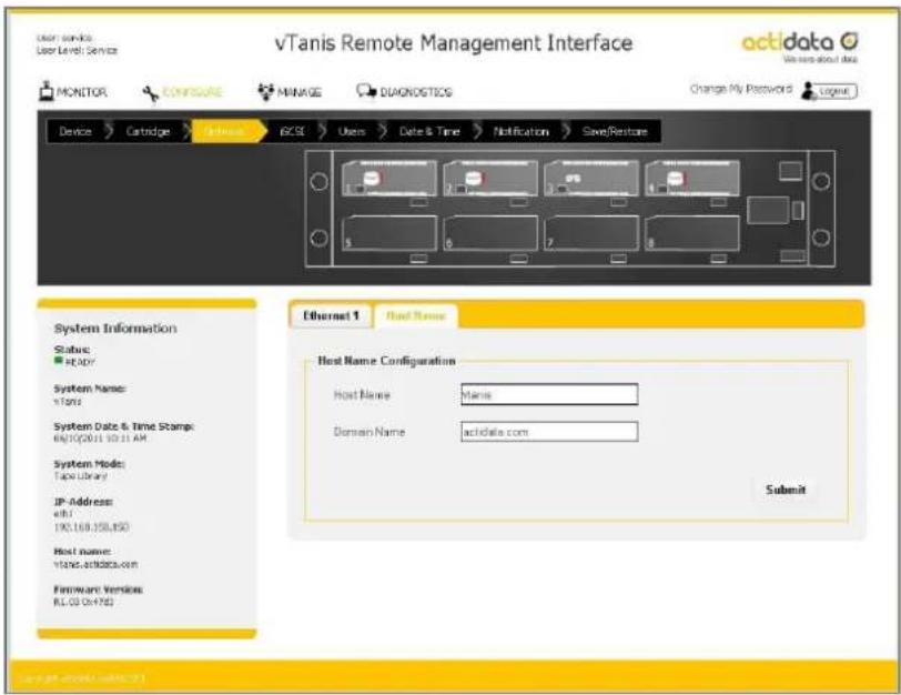
vTanis Remote Management Interface Monitor Configure MINAGE DIAGNOSTICS Change My Password Logout Device Cartridge Hardware RISC Users Date & Time Notification Save/Restore System Information Status: HKEY System Name: vTanis System Date & Time Stamp: 06/10/2011 10:11 AM System Mode: Tape Library IP Address: eIFJ 190.169.358.850 Host name: vTanis.vtitanics.com Firmware Version: RL-03-04-1783 Ethernet 1 Host Name Host Name Configuration Host Name: Manis Domain Name: actidata.com SubmitFigure 18 RMI congure hostname
Host Name:
vTanis userman 302708 Revision 12
In this box enter the name you wish to use to use to address this vTanis in the future. It is recommended that you use a name that is relevant to its locaon and or its purpose.
Domain Name:
In this box is the domain the vTanis is registered in and may be updated by eding the name and subming the changes.
In order for any changes on this page to be applied the "Submit" button must be set.
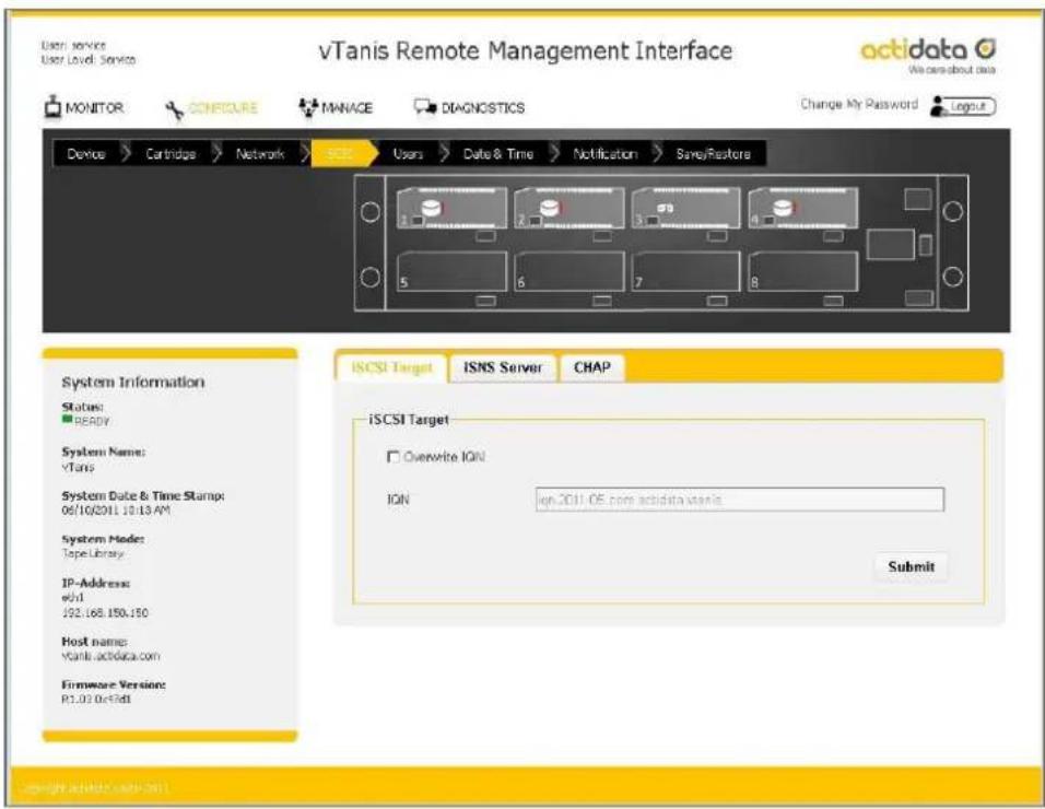
iSCSI sengs are accessed under the "CONFIGURE/iSCSI" tab, the sengs are as follows:
text_image
vTanis Remote Management Interface Monitor Configure MANAGE DIAGNOSTICS Change My Password Logout Device Cartridge Network NETC Users Date & Time Notification Save/Restore System Information Status: READY System Name: vTanis System Date & Time Stamp: 06/10/2011.10:13 AM System Mode: Tape Library IP-Address: ewd 192.168.150.150 Host name: vTanis.actdata.com Firmware Version: P1.03.0c15dt ISCSI Target ISNS Server CHAP IS CSI Target Overwrite ION ION ign.2011.05.com actdata.vtanis Submit copyright.achidata.sxt-0411.Figure 19 RMI congure iSCSI target
Overwrite IQN:
This check box will allow the administrator to assign their own unique IQN name to the vTanis unit. An IQN may be up to 255 characters long. To apply a new IQN name to the device the Overwrite IQN box is checked, the desired IQN is programmed in the IQN eld, and the submit buon is pressed to apply changes.
IQN - iSCSI Qualified Name:
iSCSI naming convenon that uniquely idenes every device. An IQN may be up to 255 characters long.
vTanis userman 302708 Revision 12
text_image
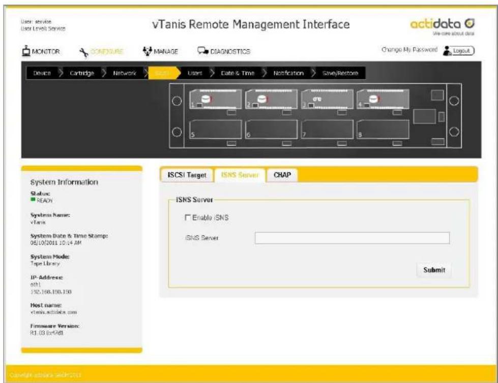
vTanis Remote Management Interface acidata We care about data MONITOR CONTINUE MANAGE DIAGNOSTICS Change My Password Logout Device > Cartridge > Network > User > Date & Time > Notification > SaveRestore 1 2 3 4 5 6 7 8 System Information Status: ■ READY System Name: vTanis System Date & Time Stamp: 06/10/2011 10:14 AM System Mode: Tape Library IP-Address: ath1 192.166.150.150 Host name: vtanis.adidas.com Firmware Version: R1.03 (or7d1) ISCSI Target ISNS Server CHAP ISNS Server Enable iSNS iSNS Server Submit Copyright structure and POSTSFigure 20 RMI congure iSNS server
Internet Storage Name Service (iSNS)
This eld allows for the automated discovery, management, and conguraon of iSCSI devices from a central point. If this opon is enabled the vTanis will register its resources with a central iSNS-server. To enable iSNS on the vTanis, click the ck box “Enable iSNS” and enter the IP address for the iSNS-Server in the “iSNS Server” eld and click the submit buon.
text_image
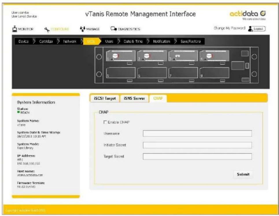
vTanis Remote Management Interface User Service User Level Service MONITOR CONCURE MANAGE DIAGNOSTICS Change My Password Layout Device > Carbridge > Network > iSCI Users > Date & Time > Modification > Save/Restore System Information Status: REACH System Name: vTani System Date & Time Stamp: 06/03/2011 10:15 AM System Mode: Tape Library IP Address: eth) 192.160.150.150 Host name: vtonis.acsfata.com Firmware Version: R1.03.0e1761 iSCSI Target iSNS Server CHAP CHAP Enable CHAP Username Initiator Secret Target Secret Submit Copyright: www.tach-2011Figure 21 RMI congure CHAP
CHAP is an authencaon scheme used by servers to validate the identity of clients and vice versa. When CHAP is enabled, the initiator must send the correct "Username" and "Target Password" to gain access to the vTanis. The "Iniator Secret" eld is provided to allow iSCSI mutual CHAP. If mutual CHAP is selected on the Iniator, the vTanis will authenticate itself with the initiator using the supplied initiator secret.
To enable CHAP click the 'Enable CHAP' tick box and enter the following details in the remaining fields:
- Username – this is the username that the iSCSI Iniator must use to gain access to the iSCSI bridge
- Iniator Secret – this is the password that the iSCSI bridge will send to the iSCSI Iniator during mutual CHAP
- Target Secret – This is the secret dened by the iSCSI bridge and will be sent from the iSCSI Iniator to authenticate the iSCSI Iniator.
The two CHAP secrets must be between 12 and 16 characters long and both Iniator and Target Secrets must be dierent.
Once the details are set the submit button must be pressed to apply the changes.
vTanis userman 302708 Revision 12
vTanis userman 302708 Revision 12
User sengs
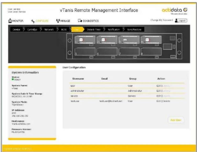
The 'Users"-tab is used by the administrator to change default passwords and/or create new users. Default passwords for the generic administrator and user elds may be changed from factory defaults by selecng the edit buon behind the associated user name. The generic administrator and user names cannot be changed however email nocaoon and password may be changed on these user accounts. The service account name and password may not be changed to preserve service personal access.
text_image
vTanis Remote Management Interface User: service User Level: Service MONITOR CONFIGURE MANAGE DIAGNOSTICS Change My Password Layout Device Cartridge Network SCSI User Data & Time Notification Sys/Restone System Information Status: READY System Names: vTanis System Date & Time Storage: 06/16/2011 10:30 AM System Mode: Tape Library IP Address: old 396.100.350.150 Host names: vTanis-achidate.com Firmware Version: PL63 Qn475J User Configuration Username Email Group Action User User Edit | Update Administrator Administrator Edit | Update Service Service Edit | Delete testuser testuser@testnet.net User Edit | Delete Add UserFigure 22 RMI congure users
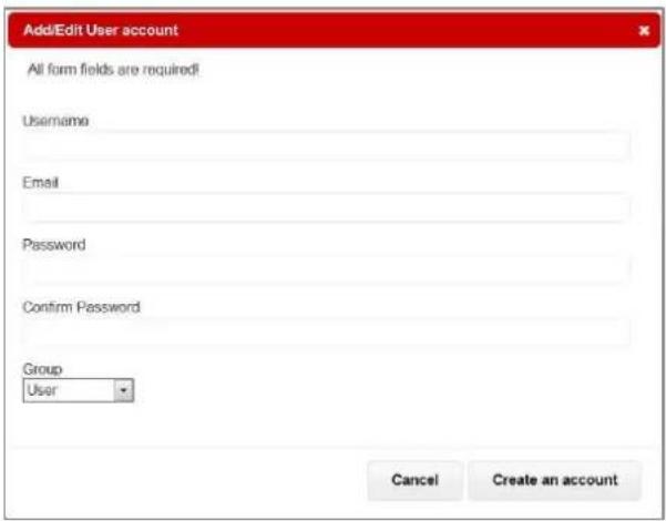
New users may be created by selecng the "Add User" buon which will pop up a screen to enter the following elds:
Username:
The log in name of the user account, this eld is limited from 3-16 characters, no special characters are allowed, must not begin with a number, and be all lower case.
Email:
This is the email address associated with this user name for status nocaons from the system. This eld must be between 6-80 characters long.
Password/Password confirmation:
vTanis userman 302708 Revision 12
The password with vericaon for the user account, this eld is must be at least 5 characters long but not more than 16 characters long, no special characters, and must not begin with a number, and be all lower case.
Group:
This drop down dialog allows the administrator to assign access rights to the account as follows
User level:
User level access only allows access to the "MONITOR" funcons of the RMI (The user cannot change any conguraon sengs/add user accounts/ or reformat/create tape format cartridges).
Administrator level:
Administrator level grants access to all funcons within the unit including "MONITOR", "CONFIGURE", "MANAGE" and "DIAGNOSTICS".
text_image
Add/Edit User account All form fields are required! Username Email Password Confirm Password Group User Cancel Create an accountFigure 23 Add/Edit user account
Date and me sengs
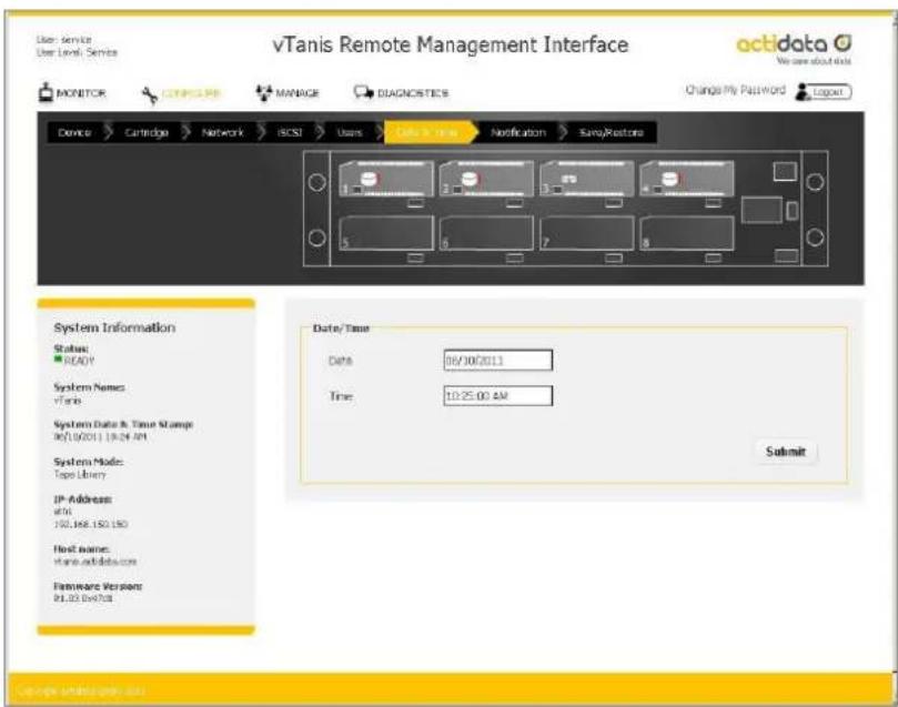
The date and me sengs screen allows the user to set the library system date and me. This me and date informaon is displayed in the system informaon block and also used for me stamping log entries and remote nocaaon messages from the vTanis unit to remote users.
text_image
vTanis Remote Management Interface User Service User Level: Service MONITOR C:\WINDOWS MANAGE DIAGNOSTICS Change My Password Logout Device Cartridge Network RCSI Users Data & Time Notification Save/Restore System Information Status: READY System Name: vTans System Date & Time Stamps 06/19/2011 19:24 AM System Mode: Tape Library IP Address: sftn: 150.168.150.150 Host name: www.adidas.com Firmware Version: 01.03.vct7d8 Date/Time Date: 06/30/2011 Time: 10:25:00 AM SubmitFigure 24 RMI congure date/me
vTanis userman 302708 Revision 12
The date may be sent by clicking in the date eld and entering the date in MM/DD/YYYY format or alternately using the calendar tool which pops up and selecng the year/month/date and then subming the change.
The me may be set by clicking in the data eld and entering the me in 24 hour me format or alternately using the me seng tool to select hours/minutes/seconds or clicking the "Now" buon which synchronizes the library me with the me of the computer hosng the RMI. Once set the changes must be updated to the unit by clicking the submit buon.
Nocaon sengs
The nocaon sengs tab has the following operators:
Enable E-mail notification check box:
When checked and a SMTP mail server is specied the vTanis unit will send email nocao on to the selected user.

text_image
vTanis Remote Management Interface MONITOR CANADA MANAGE DIAGNOSTICS Change By Password Device Cartridge Network EOSI Users Data & Time Save/Redoins SapiRis System Information Status: READY System Names: vTans System Date & Time Stamp: 04703013 1628.49 System Name: Type library IP-Address: eftl LRC 165.180.250 First name: vname.achidata.com Copyright Services: R1.000+076. Notification Configuration Enable E-Mail/Notification Notification Filter Critical Warning, Configuration and Informational Events SMTP Server Security Name Port 0 E-Mail Address Authentication Required Username Password SubmitFigure 25 RMI congure nocaon
Notification Filter:
The nocaoon lter is a drop down selector that allows the administrator to select from four classes of nocaoon as follows;
Critical Events:
The specied email address will be noed whenever severe errors requiring operator intervenon to resolve or in case of detected hardware failures.
Critical and Warning Events:
The specied email address will be noed whenever any crical events occur as well as warning events which indicate error conditions such as incorrect format cartridges for the selected operaon mode-etc.
vTanis userman 302708 Revision 12
Critical, Warning and Configuration Events:
The specied email address will be noed whenever any crical events occur, warning events occur as well as conguraon events which indicate changes in unit conguraon, operang mode, addition of users, etc.
Critical, Warning, Configuration and Informational Events:
The specied email address will be noed whenever any crical events occur, warning events occur, Conguraon Events occur as well as informaon events which indicate monitoring normal operaons.
SMTP Server:
Enter the address of the email server of the individual you would like to receive the errors of warnings.
Security:
You may select to enable either SSL/LS or STARTTLS security via the drop down selector.
Port:
Enter the send/receive port number for the email trac.
E-mail Address:
Enter the email address of the individual you would like to receive the errors and/or warnings.
Authentication:
Check if sender authencaon is required
Username:
Enter the authorized user account name for connecng to the selected SMTP server.
Password:
Enter the authorized user password for connecng to the selected SMTP server.
Save/Restore conguraon
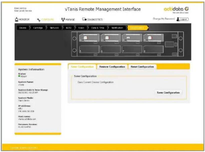
Save Configuration:
This tab allows a user to save the current user programmed conguraon values/sengs to support backup of sengs and also to support unit replacement/service. Sengs may be stored to a locaon on the RMI host computer via selecng the Save conguraon buon, downloading the le and using the browser pop up to select a storage locaon via the "Save as" funcon.
text_image
vTanis Remote Management Interface OKidata We can about date MONITOR CANADA MANAGE DIAGNOSTICS Change My Password Layout Device Cartridge Network RCD3 User Date & Time Modification Save Configuration Restore Configuration Reset Configuration System Information Status: REACH System Name: vTanis System Date & Time Settings: 06/10/2011 10:25:49 System Mode: Time Clock IP-Address: edl LNC.168.150.150 Host names: vTanis@adita.com Performance Request: PLD3@e761 Save Configuration Save Current Device Configuration Save ConfigurationFigure 26 RMI congure save/restore

It is highly recommended that once the initial unit conguraon is completed and the unit is operang properly the administrator use the save conguraon funcon to back up their unique sengs.
A soware or rear panel reset will clear all administrator added conguraon data including administrator created user accounts and nocacn sengs.
Restore Configuration:
This funcon allows a user to restore a previous user saved conguraon values/sengs from a le created by the save conguraon funcon. The le may be located by selecng the "Browse" buon within the "Restore Conguraon" tab.
vTanis userman 302708 Revision 12
Reset Configuration:
This funcon restores all factory default sengs- including reseng default passwords, IP addressing, and operang modes. Depending on network sengs reseng defaults may cause loss of communicaon with the unit or require you to adjust network sengs to regain access to the unit.

Reset conguraon may also be accomplished by using a paper clip and depressing the "Hard reset port" switch for 3 seconds then releasing.
See Page 18 for locaon of the hard reset switch on the rear panel of the unit.
Monitoring the unit cartridge and device identity/status – The MONITOR tab
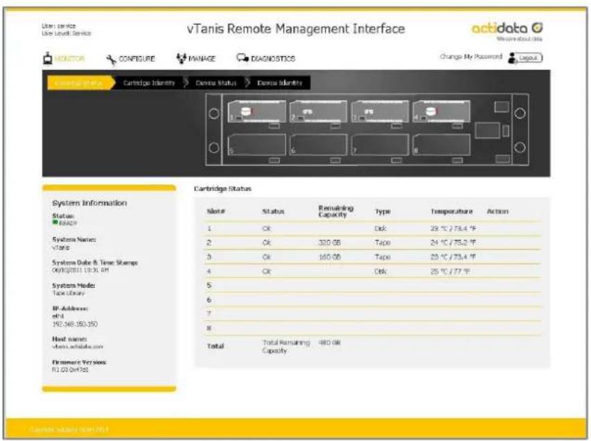
The vTanis unit user home page is the "MONITOR" tab for all account logins, following is a brief descripon of each funcon.
Cartridge status screen
Slot #:
This eld shows the row heading indicang the slot number.
Status:
Ok indicates normal operaon of the cartridge, error indicates a problem with the RDX ^® cartridge.
Remaining Capacity:
This eld shows the remaining storage capacity of the media when in tape emulaon mode only-note that in JBOD mode cartridge remaining capacity must be viewed from the host le system.
Type:
This eld indicates the format of the cartridge as either tape or disk. Using the vTanis in tape library emulaon mode requires that the cartridges be formaed as tape.
Temperature:
This eld shows the individual cartridge temperature in both Cengrade and Fahrenheit scales.
Action:
This eld is reserved for future use.
text_image
vTanis Remote Management Interface VGTdata Configure MANAGE DIAGNOSTICS Change My Password Cartridge Identity Dentaur Status Dentaur Identity Cartridge Status Status: BASOY Systems Name: V1902 Systems Date & Time Stamp OK/10/2011 10:31:00 System Mode: Tape Library IP Address: e#.1 192,348,150,150 Host names: clama.achidao.com Firmware Version: R1.03.0x192 Note Status Remaining Capacity Type Temperature Action 1 Ok Disk 29 °C / 75.4 °F 2 Ok 320 GB Tape 24 °C / 75.2 °F 3 Ok 160 GB Tape 25 °C / 73.4 °F 4 Ok Disk 25 °C / 77 °F 5 6 7 8 Total Total Remaining Capacity Cartridges installed (R1)Figure 27 RMI monitor cartridge status
Cartridge ideny screen
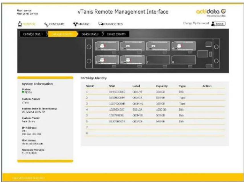
Slot #:
This eld shows the row heading indicang the slot number.
SN#:
This eld displays the physical RDX ^« cartridge serial number.
Label:
This eld displays the cartridge label, note that this label eld will always display the default cartridge label when the vTanis system is operated in JBOD mode. If the vTanis system is being operated in tape library emulaon mode using RDX ^® cartridges which have been formed as tape the label will be either the default cartridge label or if the administrator has assigned a custom label to the cartridge in the “CONFIGURE/Cartridge” menu the custom label will be displayed.
Capacity:
This eld shows the storage capacity of the RDX ^n cartridge in GB.
Type:
This eld indicates the format of the cartridge as either tape or disk. Using the vTanis in tape library emulaon mode requires that the cartridges be formaed as tape.
Action:
This eld is reserved for future use.
text_image
vTanis Remote Management Interface Cartridge Status Device Status Device Identity Cartridge Identity Status Name Label Capacity Type Action 1 01430000A9 G05J1F 320 GB Disk 2 01298000S4 G02N1K 320 GB Tape 3 10279000H8 G03MNG 360 GB Tape 4 102993X05C 9031GB 1000 GB Disk 5 10279000L G03M6D 500 GB Disk 6 0137500U52 G01P2F 640 GB Disk 7 8Figure 28 RMI monitor cartridge ideny
vTanis userman 302708 Revision 12
Device status screen
Status:
This status is the overall system status; it is also displayed in the system informaon block.
Name:
This eld displays the system name.
IP Address:
This eld displays the IP address for acve ports- this address will provide access both to RMI conncon as well as iSCSI conncon.
Total Power On Time:
This eld displays the total power on me since the last system reboot event.
Temperature:
This eld displays the current system temperature in both Cengrade and Fahrenheit scales.
Slots Free/Available:
This eld displays the number of empty cartridge slots followed by the number of slots which currently have cartridges inserted.
Library Time:
This eld displays the current library date and me from the internal system clock used for me stamping events, the library me may be sent by the administrator under the “CONFIGURE/Date & Time” tab.
Fan Speed:
This eld displays at which of 4 speeds the fan is currently running.
Fan Status:
This eld displays the running fan status (Fan OK/Fan Error). The fan status will be set to fan error if the fan is detected has not running; not running at the proper speed for selected level; or if over temperature condition is sensed.
Power Supply Status:
This eld displays the running power supply status (Power Good/Power Error) - The power status will be set to power error if any of the monitored voltages fall below or exceed normal operang parameters.
vTanis userman 302708 Revision 12
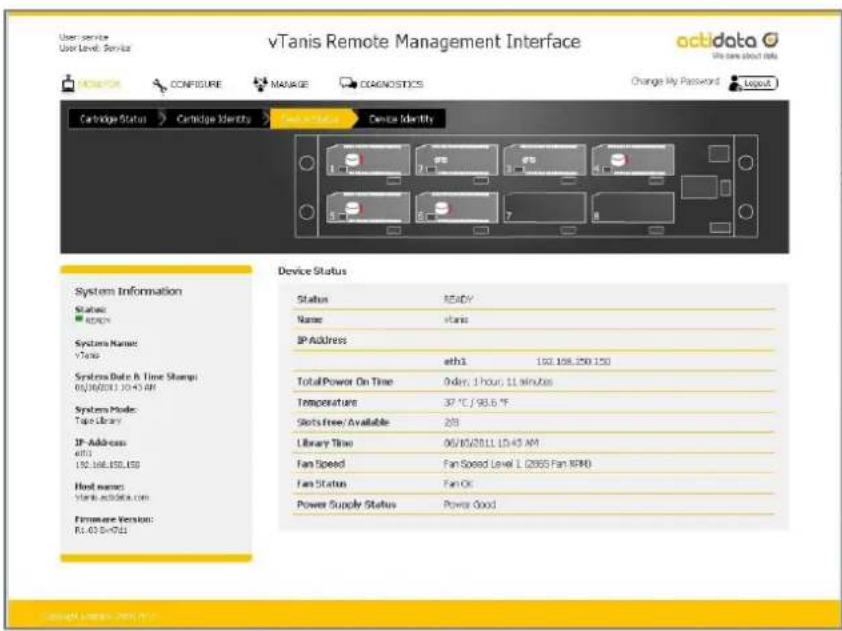
text_image
vTanis Remote Management Interface uctidata We care about this Change My Password Cartridge Status Cartridge Identity Device Identity Device Status Status READY Name vTani IP Address ath1 100.168.250.150 Total Power On Time Order: 1 hour, 11 minutes Temperature 37 °C / 98.6 °F Slots Free/ Available 228 Library Time 06/10/2011 LD43 AM Fan Speed Fan Speed Level L (2995 Fan RPM) Fan Status Fan Of Power Supply Status Power Good Systems Information Status: READY Systems Name: V Tanis Systems Date & Time Storage (01.06/03.1.10+3.0F) Systems Mode: Tape Library IP Address ath1 100.168.150.150 Host name: Harsh.ac@tate.com Firmware Version: RL-03-S=9511Figure 29 RMI monitor device status
vTanis userman 302708 Revision 12
Device Identy Screen
Vendor ID:
This eld shows the manufacturer of the vTanis device.
Product ID:
This eld shows the product name.
Serial Number:
This eld shows the master serial number of the unit.
Firmware Version:
This eld shows the current rmware revision level and rmware check sum of the unit.
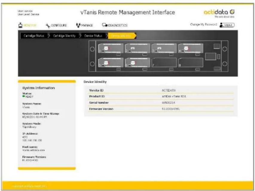
text_image
vTanis Remote Management Interface octidata The data about this Cartridge Status Catalog Identity Device Status Service Identity Device Identity Vendor ID ACTDATA Product ID actDisk vTanis HDX Serial Number 66500214 Firmware Version RL030e496L System Information Status: ACTDATA P2407 Systems Name: V1ans Systems Date & Time Storage: 05/08/2011 10:44:49 Systems Model: Tapi Library IP Address: eht1 100.166.156.150 Host names: www.wtdata.com Firmware Versions RL030e496LFigure 30 RMI monitor device identity
vTanis userman 302708 Revision 12
Access to the manage funcons is granted to administrator and service level account logins. Following are the levels of the “MANAGE” tab.
Managing the library
The “MANAGE/Library” funcon is only available when the operaon mode of the vTanis unit is set to
"Tape Library". This feature allows the user to "manually move" tape format RDX ^® cartridges from any storage slot to the drive element. The drive element allows the cartridge to be visible to the host as an emulated LTO tape within an emulated LTO tape drive and for the host to write or read data from the cartridge with applicaons designed to support LTO tape drives.
To move the cartridge the user highlights the cartridge on the storage slot side (le side of the screen) via a selecon point and click with the mouse which highlights the selecon, then selects the right poinng arrow (load drive) operator in the center of the page to move the cartridge to the drive. The cartridge will now become visible to the soware applicaon as being inserted inside the virtual tape drive. Media access commands may now be executed (Write/read/rewind/etc.) to the cartridge.
The cartridge may be unloaded from the virtual drive by selecng the le poinng arrow (unload drive) operator in the center. Also, selecng any other cartridge from the storage slot side and choosing the load buon will result in the automac unload of the cartridge in the drive. The vTanis will only store cartridges back into their original storage slot locaon (it is not possible to 'move' cartridges to a dierent storage slot.
Also the “MANAGE/Library” funcon will only allow movement of properly formaed (tape format) cartridges into the virtual drive. Cartridge format is indicated by the icon in the image for each storage slot locaon. Disk formaed cartridges will appear with the exception mark (red exclamaon mark) to indicate an abnormal condition.
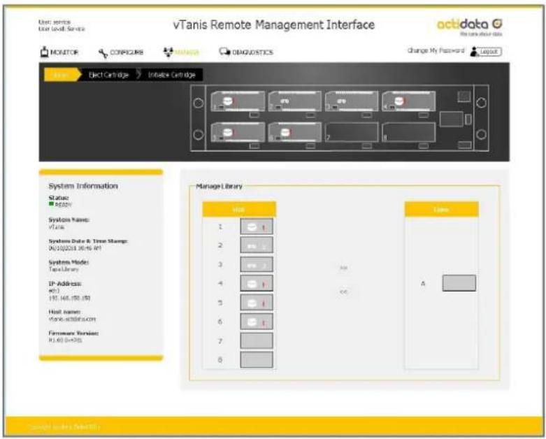
text_image
vTanis Remote Management Interface Actidaka We can't know that MOVITOR CORPICURE COMPRE DIAGUOSTICS Change My Password LAYOUT Elect Cartridge Inhibits Cartridges System Information Status: READY System Name: Vita Systems Data & Trace Manager: D:\200031.06\16.dt Systems Mode: TanaLibrary IP Address: m01 192 468 458 458 Host Name: Yamu.ac@ctidaka.com Ferware Services: RJ-63 0+555 Manage Library Unit 1 1 2 1 3 1 4 1 5 1 6 1 7 1 8 1 Users A Copyright: www.vtanis.comFigure 31 RMI manage library
Ejecng cartridges
Cartridges may be ejected by selecng the appropriate cartridge slot from the drop down menu and clicking the eject buon. Please note if the vTanis system is connected via iSCSI it will not be possible to eject cartridges via the RMI eject funcon, please eject the cartridge directly from the soware applicaon or via the eject funcon in windows.
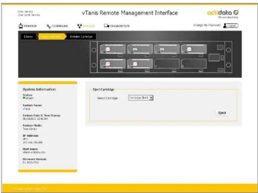
text_image
vTanis Remote Management Interface User Service User Level Services ACTi data My name about us MONITOR CONPIEUR DISCIPL DIAGNOSTICS Change My Password Logat Library Card Cartridge Injector Cartridge Systems Information Status: Reactor System Name: vTanis System Date & Time Stamps: 06/10/2011 10:40 AM System Mode: Tape Library IF-Address: ofl 192.168.192.196 Host name: vtanis.xctata.com Firmware Version: R1.000x4753 Eject Cartridge Select Cartridge Cartridge Slot1 EjectFigure 32 RMI eject cartridge
Inializing cartridges
The vTanis uses a specially format on the RDX ^® cartridges to support emulaon of tape. In order to apply this special format the administrator performs a “pre-format” operaon via the inialize cartridge funcon. This cartridge formang operaon is only necessary to perform once and it is suggested the administrator prepare all cartridges which will be used in the media pool at one me.
Preformang is only required if the system will be used in tape library mode, it is not necessary to format
RDX ^® cartridges if the system will be used as JBOD or disk changer mode.
vTanis userman 302708 Revision 12
Converng the RDX ^ cartridge into tape format mode or reformang from tape format back to disk format mode destroys any previously written user data on the cartridge (the RDX ^ cartridge will contain no user data - be blank).
For detailed informaon see:
Pre-formatting RDX® cartridges to tape library mode, Page 50
Re-formatting tape format RDX® cartridges back to standard RDX® disk, Page 51
Device Logs
The vTanis unit supports a built in event logging feature designed to facilitate monitoring and trouble shoong of the device. The logs are available for viewing under the “DIAGNOSTICS/Device Logs” tab. Within the “Device Logs” tab the user has the opon of ltering the log view as follows;
Errors:
Errors are critical events that indicate either a failure in hardware or a major soware issue. If an error is logged the vTanis unit is either non-funconal or seriously degraded. Any reported errors need invesgaon and resoluon on a high priority basis.
Warning:
Warnings are events related to potenal use problems or command failures. Warnings typically relate to either miss conguraon of the vTanis device/cartridge format or aempts to perform operaons which are logically/physically prevented within the current device state.
Configuration:
Conguraon log messages deal with system mode changes such as operaon mode sengs.
Info:
Info events log normal events indicang unit status changes which are part of normal operaons. For instance inseron and removal of RDX ^® media form each slot is monitored and logged with info events.
Clear Logs:
The device logs tab has a buon to clear the logs in the display view as well as the ability to save logs to a le which may be sent to vTanis support personal for further analysis.
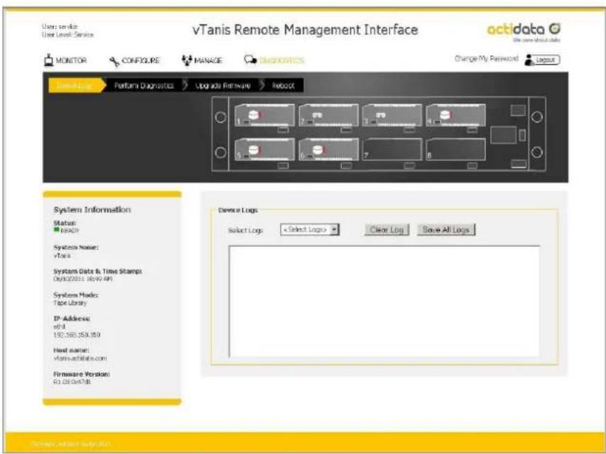
text_image
vTanis Remote Management Interface octidata User Service User Level Service MONITOR CONFIGURE MANAGE LOGISTICS Change My Password Layout System Logs Performance Diagnostics Upgrade Firmware Reboot System Information Status: 100% Systems Name: vTank Systems Date & Time Stamps Out(2021.16:49 AM) Systems Modes: Tape Library IP Address: cell 150,360,350,350 Host name: vtran-actidate.com Firmware Version: C:\20\actidate.com Device Logs Select Logs Select Logs Clear Log Save All LogsFigure 33 RMI device logs
Save All Logs:
The “Save all Logs” buon provides the capability to save the logs to a user selected locaon. The le is designed to be used by vTanis support personal to aid in problem diagnosis.
Administrator/Service run diagnoscs
The vTanis unit supports a number of interactive diagnostic tests designed to check specific areas of operation of the device. The tests are all designed to be executed locally so the unit's behavior can be observed. The tests are as follows:
Slot UI Test:
It tests each slot for eject buon indicaon and sensing- requires a local operator to interact with the unit.
Display Test:
It tests the LCD display and backlight operaon- requires a local operator to step the display with the OCP navigaon buon and observe the display through various states to conrm operaon.
Fan Test:
It tests the operaon of the vTanis cooling fan, steps the fan speed through four RPM ranges while monitoring fan rpm.
Cartridge Access Test:
It tests the operaon of each slot locaon by checking communicaon with a test cartridge.
Execuon of this test will force the unit oine and eject all inserted cartridges (this is a data safety feature to insure the test operator can use a scratch cartridge) from the unit- requires a local operator to interact with the unit.
To start the diagnosc test sequence select each test by checking each test from the list that you would like to perform and push the "Start Diagnosc" buon. You may select to run only one test or all four, upon compleon of the selected test(s) a new diagnosc log status page will be created capturing the current test status
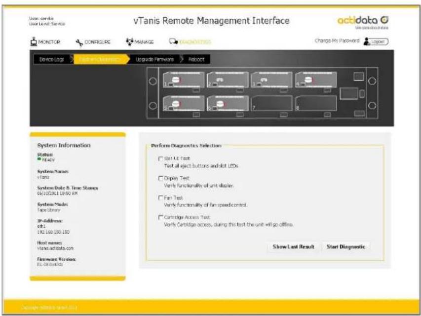
text_image
vTanis Remote Management Interface Monitor CONFIGURE MANAGE KONNOTICS Change My Password Device Log Features Maintenance Upgrade Firmware Reload System Information Status: No. 1 System Names: vTanis System Date & Time Stamp 06/12/2014 19:30 AM System Mode: Tape Library IP-Address: 0811 190 150 130 150 Host names: Hand accdata.com Firmware Version: RLOB LabDOS Perform Diagnostics Selection □ Start UI Text Text all eject buttons and slot LEDs. □ Display Text Verify functionality of unit display. □ Fan Text Verify functionality of fan speed control. □ Cartridge Access Text Verify Cartridge access, during this text the unit will go offline. Show Last Result Start DiagnosticFigure 34 RMI perform diagnoses
vTanis userman 302708 Revision 12
Slot UI Test
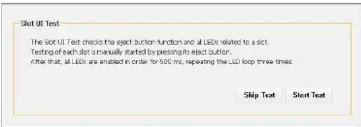
text_image
Slot UI Test The Slot UI Test checks the eject button function and all LEDs related to a slot. Testing of each slot is manually started by pressing its eject button. After that, all LEDs are enabled in order for 500 ms, repeating the LED loop three times. Skip Test Start TestTo execute the "Slot UI Test" select the "Start Test" buon which will request the operator to push each individual slot eject buon and observe the LED behavior, it will blink three mes green then three mes amber. Note that when the vTanis is in the slot UI test mode any inserted cartridge will not be ejected by the associated buon push during the test. Once all eight posions have been veried conrm compleon of a successful test by selecng "Test Passed" buon which will create a "Slot UI Test passed" status.
Display Test
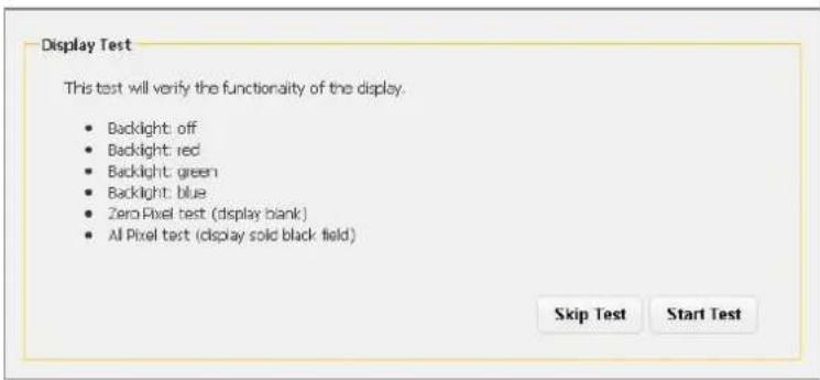
text_image
Display Test This test will verify the functionality of the display. • Backlight: off • Backlight: red • Backlight: green • Backlight: blue • Zero Pixel test (display blank) • All Pixel test (display sold black field) Skip Test Start TestTo execute the "Display Test" select the "Start Test" buon. The local operator will then be asked to push the OCP navigaon buon and observe the display. Each navigaon buon push will step the unit through a dierent display acon. The rst four steps will change the display backlight from white, to red, to green, to blue verifying proper operaon of the RGB backlight. The next two steps will rst clear all display pixels (the observer should see no dots) then set all pixels black (the observer should see no missing black dots in the eld).
vTanis userman 302708 Revision 12
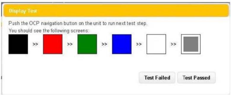
text_image
Display Test Push the OCP navigation button on the unit to run next test step. You should see the following screens: Test Failed Test PassedOnce all six display conditions have been verified conrm compleon of a successful test by selecng "Test Passed" buon which will create a "Display Test passed" status.
Fan Test
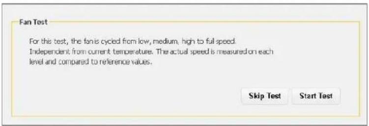
text_image
Fan Test For this test, the fan is cycled from low, medium, high to full speed. Independent from current temperature. The actual speed is measured on each level and compared to reference values. Skip Test Start TestTo execute the "Fan Test" select the "Start Test" buon. The fan will cycle through four operation speeds while monitoring the fan RPM for the correct reference value.
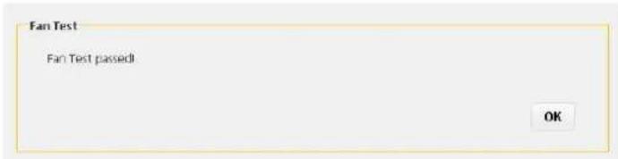
text_image
Fan Test Fan Test passed! OKOnce the fan test has completed the vTanis will report a pass/fail status and the administrator may click the "OK" buon to log the result.
Cartridge Access Test
The “Cartridge Access Test” checks the ability of each slot to properly insert/load, identify/communicate with RDX ^® media, and unload/eject RDX ^® media. The unit will be taken oine from the iSCSI conncon to prevent concurrent data access aempts from the host system. Also at the start of the test all currently inserted RDX ^® media will be bulk ejected from the unit. It is suggested the test operator use a known good cartridge which can be used to test each slot.
To execute the "Cartridge Access Test" select the "Start Test" buon, the vTanis unit will then bulk eject all currently inserted cartridges and ask the user to remove them from the unit.
vTanis userman 302708 Revision 12
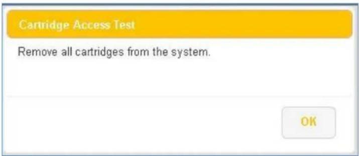
text_image
Cartridge Access Test Remove all cartridges from the system.The operator will then be asked to insert a cartridge in each of the eight slots in sequence. The vTanis unit will then perform the slot access test and eject the cartridge and provide a pass/fall status.
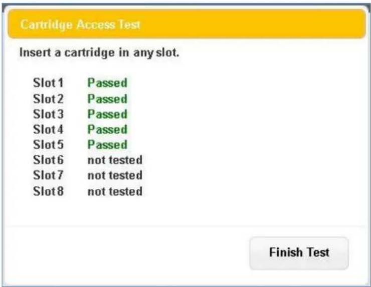
text_image
Cartridge Access Test Insert a cartridge in any slot. Slot 1 Passed Slot 2 Passed Slot 3 Passed Slot 4 Passed Slot 5 Passed Slot 6 not tested Slot 7 not tested Slot 8 not tested Finish TestUpon compleon of tesng of all eight locaons the operator can conrm "OK" which will log the results to the diagnosc test log. The operator will be instructed to place the user data cartridges back into the unit, and the unit will reconnect to the iSCSI network.
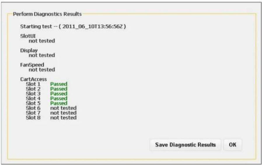
text_image
Perform Diagnostics Results Starting test -- ( 2011_06_10T13:56:562 ) SlotUI not tested Display not tested FanSpeed not tested CartAccess Slot 1 Passed Slot 2 Passed Slot 3 Passed Slot 4 Passed Slot 5 Passed Slot 6 not tested Slot 7 not tested Slot 8 not tested Save Diagnostic Results OKFigure 35 RMI diagnoses passed
Upgrade Firmware
The vTanis “DIAGNOSTICS” menu also supports the ability to upgrade the unit operang rmware via the “DIAGNOSTICS/Upgrade Firmware” tab. To upgrade the rmware the user must have a valid vTanis rmware upgrade image available on the RMI host computer. Released rmware images are available via the vTanis support team. vTanis rmware images have an “.i” le extension and are approximately \~22MB in size.
To upgrade the rmware select the “Upgrade Firmware” tab and you the “Browse” buon to set a path to the vTanis rmware le located on the computer system connect via RMI, and then select the “Upgrade” buon. The unit will proceed with the upgrade and reboot aer the new code is installed. It will be necessary to log back into the RMI to regain access to the management interface.
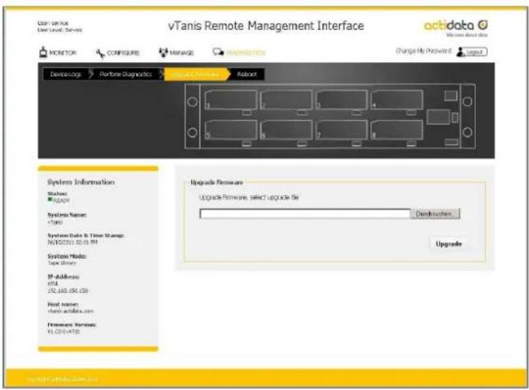
text_image
vTanis Remote Management Interface Monitor Configure Manage Change My Password Device Logs Performance Diagnostics Integrated Remote Robot octidata Windows about data System Information Status: READY Systems Request: 1/10 Systems Data & Time Storage: N:500000 50:01 PM System Mode: Type Library IP-Address: nHL JNJ.869.956.150 Host name: Home.xntube.com Hardware Version: PLC204-AT56 Upgrade Hardware Upgrade Provider, select upgrade file Distributes UpgradeFigure 36 RMI upgrade rmware
Reboot consideraons
The vTanis may be rebooted remotely via the “DIAGNOSICS/Reboot” tab selecng the “Reboot” tab and acvang the “Reboot” buon in the RMI. Reboong the unit takes approximately 2 minutes and will require the administrator to log in to the RMI again aer the reboot process is complete.
vTanis userman 302708 Revision 12
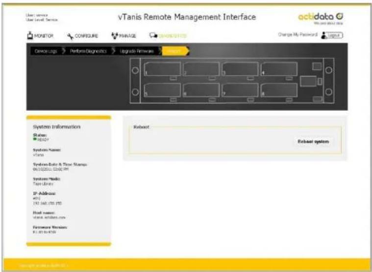
text_image
vTanis Remote Management Interface VGTdata My name about this MONITOR CONFIGURE MANAGE ONIONAL ITEMS Change My Password Login Device Logs Perform Diagnostics Upgrade Firmware System Information Status: REBOOT Systems Name: vTans Systems Rate & Time Stamps: 061020011.02.20PM Systems Media Type Library IP Address: mRS 753 JAPL/USB PDS Host name: www.wttnics.com/ Hardware Version: KJ 03 to KJ50 Reboot Reboot systemFigure 37 RMI reboot system
RDX ^® cartridges
This chapter describes the use of the RDX ^® cartridge in the vTanis. The RDX ^® cartridge ulizes a removable 2.5" mobile HDD to oer the reliability and performance of disk technology along with the manageability of removable media.
For physical and functional speciaons, please see chapter Product specification, Page 96.
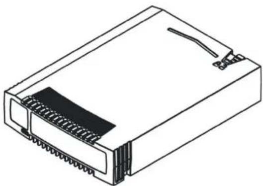
natural_image
Line drawing of a computer internal component with slots and connectors (no text or symbols)Figure 38 Cartridge overview
RDX ^® cartridges contain HDDs with SATA I or SATA II interfaces capable of transferring data at either 1,5 GB/s or 3,0 GB/s.
Write-protecng cartridges
The write protect slider is located on the top right rear of the cartridge. With the slider and in the right most posion, the cartridge is shown to be writable (un-locked) and in the le most posion the cartridge is shown to be write-protected (locked).
vTanis userman 302708 Revision 12
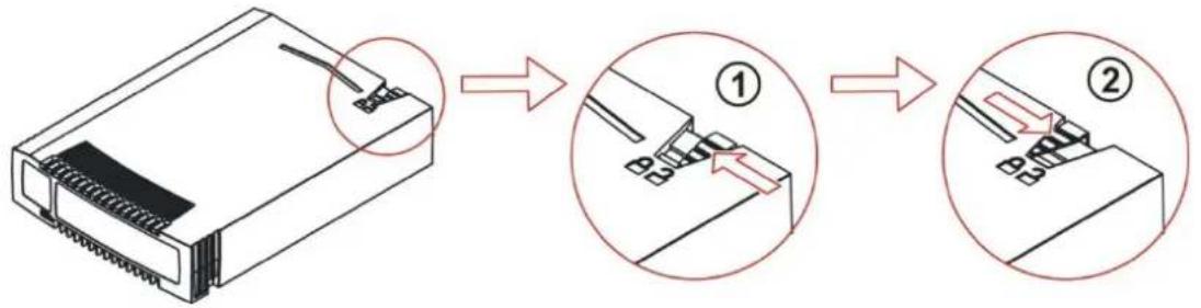
text_image
Diagram illustrating the step-by-step assembly of a device, showing connection to a connector and disassembly with numbered steps.Figure 39 Write-protecng cartridges
| Number | Description |
| 1 | Cartridge is writable. |
| 2 | Cartridge is write-protected. |
Inserng cartridges
- Find an empty RDX ^e cartridge slot (8 places) in the unit to be inserted.
- Push the RDX ^a cartridge gently into the cartridge slot until it seats itself against the back of the unit.
- Verify that the cartridge is properly inserted. When the cartridge indicator LED is steady green the cartridge is ready.
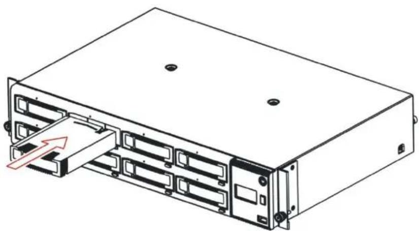
natural_image
Diagram of a server rack with multiple ports and an internal drive, showing no text or symbols.Figure 40 Inserng cartridges
Ejecng cartridges
The vTanis unit has three possibilities to eject cartridges:
- Ejecng individual cartridges with the front panel cartridge eject buon (when allowed by applicaon) or when the unit is oine (not connected to an iSCSI host).
- Ejecng cartridges through the vTanis RMI interface see chapter
vTanis userman 302708 Revision 12
- Ejecting cartridges, Page 79.
- Manually ejecting cartridges with the emergency eject port when the unit power is or in error conditions.
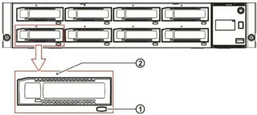
text_image
Diagram showing server rack with labeled components and a zoomed-in view of the internal structure.Figure 41 Ejecng cartridges
Press the cartridge eject buon ① to eject the cartridge. If the cartridge does not eject, use the following emergency methods to recover the cartridge:
- Power down the vTanis.
- Insert a straightened paper clip into the emergency eject port unl resistance is felt, indicating the paper clip is contacting the emergency eject rod, provide a rm push in ② to eject the cartridge.

When using the emergency eject feature the force should be applied to the paper clip in a straight line (paper clip held square (90 degrees) in both the horizontal and vercal planes) pushing in toward the front bezel. Avoid applying force to the emergency eject port in any other direcon or damage may occur.
Appendix
Product specification
Physical specicaon & Funconal specicaon
Mechanical dimension and unit height
- Unit Height: 2U with clearance for units above and below
- Unit Depth: Less than 12" (excluding connectors)
- Unit Width: Fits standard 19" computer racks
- Standalone Unit Weight, (without a disk): 6,0 kg
- Packaged Unit Weight, (with accessory kit, without disks): 8,0 kg
- Single Disk Weight (without plasc box): 0.170 kg
- Single Packaged Disk Weight (with plasc box): 0.240 kg
Operang Temperature: +10° - +35°C
Operang Temperature Gradient: 10°C/hour
Storage Temperature: -30^-+60^
Non-operang Temperature Gradient: 20°C/hour
Relave Humidity Operang: 20 – 80 % non-condensing
Relave Humidity Non-operang: 20 – 90 % non-condensing
Operang humidity Gradient: 10% r.h./hour
Non-operang Humidity Gradient 10°C/hour
vTanis userman 302708 Revision 12
Altude Operang: 0 to 10,000 feet (3000 m) at 25°C ambient
Altitude Storage: -22 – 30,000 feet
Input voltage: 100-240 VAC, 50-60 Hz
Input power, Unit standby: 0,7 W
Input power, Unit ready: 17 W
Input power, Unit read/write 1 Cartridge: 20 W
Input power, Unit read/write 8 Cartridge: 32 W
Power Supply key parameters:
- Wide Range Input Voltage: 90-264 VAC
- Total Output Power: 100W (with fan cooling, 80W with convecon cooling
• Output Voltage: 15 VDC
• Eciency: >85% (Cercaon 80 PLUS Bronze) - Input power <1,0 W with 10mA output load
- Hold up me >15 ms
- EMI class A
• MTBF > 250 k hours
Regulatory Requirements
Product Safety:
- CB Report and Cercaon with all naonal deviaons, according:
• IEC 60950-1:2005
• EN 60950-1:2006 + A11:2009
• UL 60950-1 Issued 2007/03/27 Ed. 2
• CSA-C22.2 No. 60950 Issued 2007/03/01 Ed. 2
Emission:
• IEC CISPR 22:2008-09 Ed. 6.0 Limit: Class A
• EN 55022:2006 + A1:2007 Limit: Class A
• FCC: 47CFR Part 15B:2008-07
Limit: Class A (Test acc. to CISPR 22)
• ICES-003, Issue 4 2004-03 Limit: Class A (Test acc. to CISPR 22)
• AS/NZS 3548:1995 + A1/A2:1997 Limit: Class A
• VCCI V-3 2009-04 in parts (Japan) Limit: Class A
• VCCI V-4 2009-04 in parts (Japan) Limit: Class A
• EN 61000-3-2:2006
• EN 61000-3-3:1995 + A1:2001 + A2:2005
Immunity:
• EN 55024:1998 + A1:2001 + A2:2003
(Requires tests according to the actual versions of:
o IEC 61000-4-2
o IEC 61000-4-3
o IEC 61000-4-4
o IEC 61000-4-5
vTanis userman 302708 Revision 12
o IEC 61000-4-6
o IEC 61000-4-8
o IEC 61000-4-11 (Limits acc. to EN 55024:1998)
CRU replacement
Power supply
The power supply is a CRU (Customer Replaceable Unit). The power supply is located on the rear side of the unit and is xed with two thumb screws. The power supply is capable to power up to 8 cartridges simultaneously while supporting other unit electronics (controller, LED's, OCP, motors).
For technical specicaon, see chapter Product specification, Page 96.
Removing a power supply
- Power down the unit by pressing the power buon on the front panel.
- Locate the power supply on le side on the rear panel of the vTanis unit, shown in chapter Rear panel layout, Page 18.
- Remove the power cord on the rear panel of the unit.
- Loosen the two thumbscrews located on the rear of the power supply using a #3 Phillips screwdriver or your ngers.
- Pull the power supply straight out of the unit.
- To store or ship the removed power supply, repackage it in the original or replacement device packaging materials.
Installing a power supply
- Locate the power supply bay on le side on the rear panel of the vTanis unit, shown in chapter Rear panel layout, Page 18.
- Before installing the power supply, inspect the connectors on the power supply. Ensure that the connectors are intact, free of any foreign objects, and have no cracks or deformed or bent contacts.
- Insert the power supply on the alignment rails and push the power supply into the power supply bay until it seats itself against the back of the unit, see Figure 42.
vTanis userman 302708 Revision 12
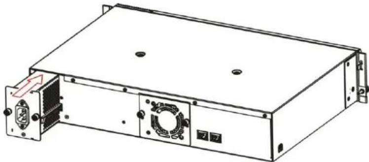
natural_image
Technical line drawing of a server rack unit with mounting holes and ventilation slots (no text or symbols)Figure 42 Installing a power supply
- Tighten the two thumbscrews using a #3 Phillips screwdriver or your ngers to secure the power supply to the unit.
Cooling fan
The cooling fan is a CRU (Customer Replaceable Unit)). The fan is located on the rear side of the unit and is xed with 2 thumb screws. The fan is speed controlled. The speed varies in 4 steps (low, medium, high and max) and is controlled by a micro controller and thermal sensors.
For technical specicaon, see chapter Product specification, Page 96.
- Power down the unit by pressing the power buon on the front panel.
- Locate the cooling fan on the middle of the rear panel of the unit, shown in chapter Rear panel layout, Page 18.
- Remove the power cord on the rear panel of the unit.
- Loosen the two thumbscrews located on the rear of the cooling fan using a #3 Phillips screwdriver or your ngers.
- Pull the cooling fan straight out from the rear of the unit.
- To store or ship the removed cooling fan, repackage it in the original or replacement device packaging materials.
- Locate the cooling fan bay on the middle of the rear panel of the vTanis unit, shown in chapter Rear panel layout, Page 18.
- Before installing the cooling fan, inspect the connectors on the cooling fan CRU and the mang connector in the vTanis unit. Ensure that the connectors are intact, free of any foreign objects, and have no cracks or deformed or bent contacts.
- Push the cooling fan straight into the cooling fan bay until it seats itself against the back of the unit, see Figure 43.
vTanis userman 302708 Revision 12
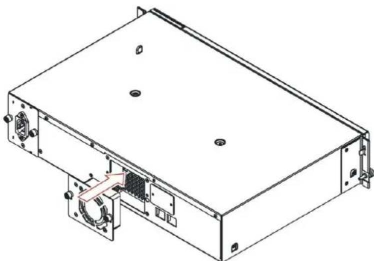
natural_image
Technical line drawing of a rectangular electronic device with mounting holes and internal components (no text or symbols)Figure 43 Installing a cooling fan
- Tighten the two thumbscrews using a #3 Phillips screwdriver or your ngers to secure the cooling fan to the unit.
Base chassis
Removing the base chassis
To prepare the base chassis removal, adhere strictly the following steps:
- If the OCP or RMI works:
• Write down the system, cartridge and network conguraon sengs.
You will need these sengs to re-congure the vTanis unit aer replacing the base chassis.
- Remove all cartridges; see chapter Ejecting cartridges, Page 94.
- If the OCP or RMI does not work:
- Remove the cartridges manually from the unit; see chapter Ejecting cartridges, Page 94.
-
Power down the vTanis by pressing the power buon on the front panel.
-
Remove the cables on the rear panel of the unit.
-
Remove the power supply; see chapter Removing a power supply, Page 100.
-
Remove the cooling fan; see chapter Removing a cooling fan, Page 102.
To remove the base chassis from the rack, adhere strictly the following steps:
- Using a #3 Phillips screwdriver or your ngers to loosen the two capve thumb screws on each side of the unit.
- Remove the unit from the rack rails.
- Remove the rack ears of the unit using T10 Torx screwdrivers to loosen the torx screws on each side of the unit.
- To store or ship the removed base chassis, repackage it careful in the original packaging materials, see chapter Packaging, Page 106.
Replacing the base chassis
Use this procedure to replace the base chassis with another base chassis:
- To remove the base chassis from the rack, see chapter Removing the base chassis, Page 104.
vTanis userman 302708 Revision 12
- To install the new base chassis and its components, see
vTanis; see chapter Product installation, Page 21.
Power supply; see chapter Installing a power supply, Page 100.
Cooling fan; see chapter Installing a cooling fan, Page 102.
Packaging
• vTanis Device without cartridges
• Power Cable US, UK, GE
- Rack mount Kit
- Screws for rack mount kit
- Network Cable
Glossary
| CRU | Customer Replaceable Unit is easily replaceable module designed to enable customer serviceability of the vTanis unit. CRU's can be exchanged by the end use customer without tools to support eld renew/repair of either the cooling fan or power supply system. |
| DHCP | The Dynamic Host Configuration Protocol is an automac conguraon protocol used on IP networks. Computers that are connected to IP networks must I congured before they can communicate with other computers on the network. DHCP allows a computer to be congured automacally. |
| DNS | The Domain Name System is a hierarchical naming system built on a distributed database for computers, services, or any resource connected to the Internet or a private network. Most importantly, it translates domain names meaningful to humans into the numerical ideners associated with networking equipment for the purpose of locang and addressing these devices worldwide. |
| Disk | Refers either to a HDD unit or the direct block addressing scheme used to store and retrieve digital data on the HDD. When the vTanis unit is in disk mod direct block addressing is used to access the contained RDX ^® media. |
| ESD | Electro Static Discharge is the sudden and momentary electric current that ows between two objects at dierent electrical potenals The term is usually used in the electronics and other industries to describe momentary unwanted currents that may cause damage to electronic equipment. |
| HDD | Hard Disk Drive refers to the core storage device using rotang magnec media to store digital informaon. RDX ^® cartridges make use of embedded HDD's to store data. |
| iSCSI | Internet Small Computer System Interface, an Internet Protocol (IP)-based storage networking standard for linking data storage facilities. By carrying SCSI commands over IP networks. |
| iSNS | Internet Storage Name Service, protocol that allows automated discovery, management and conguraon of iSCSI devices on a TCP/IP network. |
| LED | Light Emitting Diode is a semiconductor light source. The vTanis uses LED's to provide power switch, eject buon, and cartridge status indicaon. LED technology is also used to provide the backlighng for the LCD display used in the OCP. |
| MTU | In computer networking, the Maximum Transmission Unit of a communicaons protocol of a layer is the size (in bytes) of the largest protocol data unit that the layer can pass onwards. MTU parameters usually appear in associaon with a communicaons interface (NIC, serial port, etc.). |
| OCP | Operator Control Panel includes display, buons and LED's and enables the user to operate the unit from the front |
| RDX | Is a removable disk technology developed by ProStor. |
| RMI | Remote Management Interface provides the capability to operate the unit through a web based remote management interface |
| SCSI | Small Computer System Interface is a set of standards for physically connecng and transferring data between computers and peripheral devices. The vTan uses the SCSI protocol transmied via iSCSI packets over the user's computer network. |
| SMI-S | SMI-S, or the Storage Management Initiative Specification, is a storage standard developed and maintained by the Storage Networking Industry Associaon (SNIA). It has also been raed as an ISO standard. SMI-S is based upon the Common Informaon Model (CIM) and the Web-Based Enterprise Management (WBEM) standards dened by the Distributed Management Task Force (DMTF), which dene management funconality via HTTP. The most recent approved version of SMI-S is available at the SNIA. |
| SNMP | Simple Network Management Protocol is an Internet-standard protocol for managing devices on IP networks. Devices that typically support SNMP include routers, switches, servers, workstaons, printers, modem racks, and more. It is used mostly in network management systems to monitor network-aached devices for condions that warrant administrave aenon. |
| USB | Universal Serial Bus is an interface designed to provide high speed conneccon of various device types in a hot pluggable manner. The vTanis system has one USB 2.0 port located on the front panel for various operaons (rmware version dependent) |
Trademarks:
RDX ^® is a registered trademark of ProStor Systems Inc.
vTanis userman 302708 Revision 12
Linear Tape Open, LTO, The LTO logo, ULTRIUM, and the ULTRIUM logo are registered trademarks of HP, IBM, and Quantum in the US and other countries.
All other trademarks are the property of their respective owners.
List of figures
Figure 1 Front panel 14
Figure 2 Rear panel.... 18
Figure 3 Ethernet port 20
Figure 4 Installing the rack ears 26
Figure 5 Securing the unit to the rack 27
Figure 6 Power up/down the unit....30
Figure 7 RMI ow chart 32
Figure 8 RMI log in screen page 33
Figure 9 RMI log in detail 34
Figure 10 RMI home page 36
Figure 11 RMI system informaon 38
Figure 12 OCP cartridge status....41
Figure 13 RMI congure device 47
Figure 14 RMI congure inquiry string.... 49
Figure 15 RMI inialize cartridge 51
Figure 16 RMI congure cartridge....52
Figure 17 RMI congure Ethernet 53
Figure 18 RMI congure hostname 55
Figure 19 RMI congure iSCSI target....57
Figure 20 RMI congure iSNS server 58
Figure 21 RMI congure CHAP 59
Figure 22 RMI congure users....61
Figure 23 Add/Edit user account 63
Figure 24 RMI congure date/me....63
Figure 25 RMI congure nocacn....65
Figure 26 RMI congure save/restore 68
Figure 27 RMI monitor cartridge status 71
Figure 28 RMI monitor cartridge ideny....73
Figure 29 RMI monitor device status....75
Figure 30 RMI monitor device identity 76
Figure 31 RMI manage library....78
Figure 32 RMI eject cartridge 79
Figure 33 RMI device logs....82
Figure 34 RMI perform diagnoses 84
vTanis userman 302708 Revision 12
Figure 35 RMI diagnoses passed 89
Figure 36 RMI upgrade rmware 90
Figure 37 RMI reboot system 91
Figure 38 Cartridge overview 92
Figure 39 Write-protecng cartridges.... 93
Figure 40 Inserng cartridges....94
Figure 41 Ejecng cartridges....95
Figure 42 Installing a power supply....101
Figure 43 Installing a cooling fan .... 103
List of tables
Table 1 Operaon modes.... 13
Table 2 Front panel 15
Table 3 Rear panel....19