Mini Swipe Reader (USB) - Payment terminal MagTek - Free user manual and instructions
Find the device manual for free Mini Swipe Reader (USB) MagTek in PDF.


User questions about Mini Swipe Reader (USB) MagTek
0 question about this device. Answer the ones you know or ask your own.
Ask a new question about this device
Download the instructions for your Payment terminal in PDF format for free! Find your manual Mini Swipe Reader (USB) - MagTek and take your electronic device back in hand. On this page are published all the documents necessary for the use of your device. Mini Swipe Reader (USB) by MagTek.
USER MANUAL Mini Swipe Reader (USB) MagTek
Technical Support: (651) 415-6800
www.magtek.com
Copyright© 2001-2009
MagTek ^© , Inc.
Printed in the United States of America
Information in this document is subject to change without notice. No part of this document may be reproduced or transmitted in any form or by any means, electronic or mechanical, for any purpose, without the express written permission of MagTek, Inc.
MagTek is a registered trademark of MagTek, Inc.
USB (Universal Serial Bus) Specification is Copyright© 1998 by Compaq Computer Corporation, Intel Corporation, Microsoft Corporation, NEC Corporation.
REVISIONS
| Rev Number | Date Notes | |
| 1 15 Jun | 01 Initial Release | |
| 2 22 Jun | 01 Section 4 | On Tracks 1, 2, and 3 Decode Status delete “more than eight bits of data” and add “data on it that is not noise.” From Card Encode Type, Value 3, delete “This device does not detect blank cards so this value will never occur.” |
| 3 25 Jul | 01 Front Matter: Agency Approvals: Corrected Class B for CE. | |
| 4 17 Aug | 01 Section 4, Report Descriptor: Changed Logical Maximum from 25 ff to 26 ff 00. | |
| 5 12 Dec | 02 Section 4, Command Number: Corrected GET and SET PROPERTY descriptions. | |
| 6 28 Jan | 03 Changed copyright symbol so pdf copies would print on all printers | |
| 7 03 Jun | 03 Front Matter: added ISO line to logo, changed Tech Support phone number, added new warranty statement. | |
| 8 17 May | 05 Included references to new commands added after June 2005. Sec 4: Replaced all of Section 4. | |
| 9 22 Nov | 05 Sec 1: To Hardware Configuration Table, added P/N 21040139.Corrected cable descriptions for Models 21040119 and 21040139. | |
| 10 30 Aug | 06 Added dual head models 21040140 and 21040146 | |
| 11 19 Mar | 07 Add Sure Swipe title and content | |
| 12 23 Mar | 09 Added M TBF Specification; updated warranty and agency approval information |
LIMITED WARRANTY
MagTek warrants that the products sold pursuant to this Agreement will perform in accordance with MagTek's published specifications. This warranty shall be provided only for a period of one year from the date of the shipment of the product from MagTek (the “Warranty Period”). This warranty shall apply only to the “Buyer” (the original purchaser, unless that entity resells the product as authorized by MagTek, in which event this warranty shall apply only to the first repurchaser).
During the Warranty Period, should this product fail to conform to MagTek's specifications, MagTek will, at its option, repair or replace this product at no additional charge except as set forth below. Repair parts and replacement products will be furnished on an exchange basis and will be either reconditioned or new. All replaced parts and products become the property of MagTek. This limited warranty does not include service to repair damage to the product resulting from accident, disaster, unreasonable use, misuse, abuse, negligence, or modification of the product not authorized by MagTek. MagTek reserves the right to examine the alleged defective goods to determine whether the warranty is applicable.
Without limiting the generality of the foregoing, MagTek specifically disclaims any liability or warranty for goods resold in other than MagTek's original packages, and for goods modified, altered, or treated without authorization by MagTek.
Service may be obtained by delivering the product during the warranty period to MagTek (1710 Apollo Court, Seal Beach, CA 90740). If this product is delivered by mail or by an equivalent shipping carrier, the customer agrees to insure the product or assume the risk of loss or damage in transit, to prepay shipping charges to the warranty service location, and to use the original shipping container or equivalent. MagTek will return the product, prepaid, via a three (3) day shipping service. A Return Material Authorization (“RMA”) number must accompany all returns. Buyers may obtain an RMA number by contacting Technical Support at (888) 624-8350.
EACH BUYER UNDERSTANDS THAT THIS MAGTEK PRODUCT IS OFFERED AS IS. MAGTEK MAKES NO OTHER WARRANTY, EXPRESS OR IMPLIED, AND MAGTEK DISCLAIMS ANY WARRANTY OF ANY OTHER KIND, INCLUDING ANY WARRANTY OF MERCHANTABILITY OR FITNESS FOR A PARTICULAR PURPOSE.
IF THIS PRODUCT DOES NOT CONFORM TO MAGTEK'S SPECIFICATIONS, THE SOLE REMEDY SHALL BE REPAIR OR REPLACEMENT AS PROVIDED ABOVE. MAGTEK'S LIABILITY, IF ANY, SHALL IN NO EVENT EXCEED THE TOTAL AMOUNT PAID TO MAGTEK UNDER THIS AGREEMENT. IN NO EVENT WILL MAGTEK BE LIABLE TO THE BUYER FOR ANY DAMAGES, INCLUDING ANY LOST PROFITS, LOST SAVINGS, OR OTHER INCIDENTAL OR CONSEQUENTIAL DAMAGES ARISING OUT OF THE USE OF, OR INABILITY TO USE, SUCH PRODUCT, EVEN IF MAGTEK HAS BEEN ADVISED OF THE POSSIBILITY OF SUCH DAMAGES, OR FOR ANY CLAIM BY ANY OTHER PARTY.
LIMITATION ON LIABILITY
EXCEPT AS PROVIDED IN THE SECTIONS RELATING TO MAGTEK'S LIMITED WARRANTY, MAGTEK'S LIABILITY UNDER THIS AGREEMENT IS LIMITED TO THE CONTRACT PRICE OF THIS PRODUCT.
MAGTEK MAKES NO OTHER WARRANTIES WITH RESPECT TO THE PRODUCT, EXPRESSED OR IMPLIED, EXCEPT AS MAY BE STATED IN THIS AGREEMENT, AND MAGTEK DISCLAIMS ANY IMPLIED WARRANTY, INCLUDING WITHOUT LIMITATION ANY IMPLIED WARRANTY OF MERCHANTABILITY OR FITNESS FOR A PARTICULAR PURPOSE.
MAGTEK SHALL NOT BE LIABLE FOR CONTINGENT, INCIDENTAL, OR CONSEQUENTIAL DAMAGES TO PERSONS OR PROPERTY. MAGTEK FURTHER LIMITS ITS LIABILITY OF ANY KIND WITH RESPECT TO THE PRODUCT, INCLUDING ANY NEGLIGENCE ON ITS PART, TO THE CONTRACT PRICE FOR THE GOODS.
MAGTEK'S SOLE LIABILITY AND BUYER'S EXCLUSIVE REMEDIES ARE STATED IN THIS SECTION AND IN THE SECTION RELATING TO MAGTEK'S LIMITED WARRANTY.
FCC WARNING STATEMENT
This equipment has been tested and was found to comply with the limits for a Class B digital device pursuant to Part 15 of FCC Rules. These limits are designed to provide reasonable protection against harmful interference when the equipment is operated in a residential environment. This equipment generates, uses, and can radiate radio frequency energy and, if not installed and used in accordance with the instruction manual, may cause harmful interference with radio communications. However, there is no guarantee that interference will not occur in a particular installation.
FCC COMPLIANCE STATEMENT
This device complies with Part 15 of the FCC Rules. Operation of this device is subject to the following two conditions: (1) this device may not cause harmful interference, and (2) this device must accept any interference received, including interference that may cause undesired operation.
CANADIAN DOC STATEMENT
This digital apparatus does not exceed the Class B limits for radio noise from digital apparatus set out in the Radio Interference Regulations of the Canadian Department of Communications.
This Class B digital apparatus complies with Canadian ICES-003.
Testing for compliance with CE requirements was performed by an independent laboratory. The unit under test was found compliant with standards established for Class B devices.
UL/CSA
This product is recognized per Underwriter Laboratories and Canadian Underwriter Laboratories 1950.
RoHS STATEMENT
When ordered as RoHS compliant, this product meets the Electrical and Electronic Equipment (EEE) Reduction of Hazardous Substances (RoHS) European Directive 2002/95/EC. The marking is clearly recognizable, either as written words like “Pb-free”, “lead-free”, or as another clear symbol (Pb).
TABLE OF CONTENTS
SECTION 1. FEATURES AND SPECIFICATIONS....1
USB HID SWIPE READER....1
USB HID SURESWIPE....1
FEATURES 2
HARDWARE CONFIGURATIONS 3
ACCESSORIES 3
REFERENCE DOCUMENTS....3
SPECIFICATIONS 4
SECTION 2. INSTALLATION....7
USB CONNECTION 7
WINDOWS PLUG AND PLAY SETUP 8
MOUNTING....8
SECTION 3. OPERATION....11
LED INDICATOR 11
CARD READ 11
SECTION 4. USB COMMUNICATIONS....13
HID USAGES 13
REPORT DESCRIPTOR 14
CARD DATA 15
TRACK 1 DECODE STATUS....15
TRACK 2 DECODE STATUS....15
TRACK 3 DECODE STATUS....16
TRACK 1 DATA LENGTH....16
TRACK 2 DATA LENGTH....16
TRACK 3 DATA LENGTH....16
CARD ENCODE TYPE 16
TRACK DATA 17
TRACK 1 DATA 17
TRACK 2 DATA 17
TRACK 3 DATA....17
COMMANDS....17
COMMAND NUMBER 18
DATA LENGTH 18
DATA....18
RESULT CODE....18
GET AND SET PROPERTY COMMANDS....18
SOFTWARE ID PROPERTY 19
SERIAL NUM PROPERTY 20
POLLING INTERVAL PROPERTY 20
MAX PACKET SIZE PROPERTY 21
TRACK ID ENABLE PROPERTY 22
INTERFACE_TYPE PROPERTY 23
RESET_DEVICE COMMAND....24
SECTION 5. DEMO PROGRAM....25
INSTALLATION....25
OPERATION 25
SOURCE CODE 26
FIGURES AND TABLES
FIGURE 1-1. USB SWIPE READER ...... VI
TABLE 1-1. SPECIFICATIONS....4
FIGURE 1-2. DIMENSIONS....5
FIGURE 2-1. READER CABLE AND CONNECTOR....7
TABLE 2-1. 4-PIN CONNECTOR 7
FIGURE 2-2. MOUNTING HOLE DIMENSIONS FOR SURFACE....9
text_image
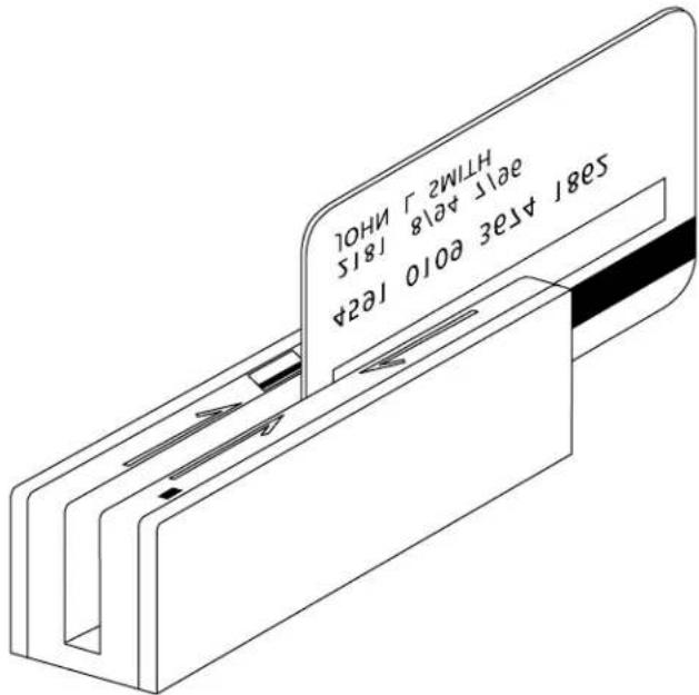
628 Ares e010 Ie24 aer i ae\8 1815 HTIM2 J HOLFigure 1-1. USB Swipe Reader
SECTION 1. FEATURES AND SPECIFICATIONS
USB HID SWIPE READER
The USB (Universal Serial Bus) HID (Human Interface Device) Swipe Reader is a compact magnetic stripe card reader with a single read head that conforms to ISO standards. The Reader is compatible with any device with a host USB interface. A card is read by sliding it, stripe down and facing the LED side, through the slot either forward or backward.
A LED (Light Emitting Diode) indicator on the Reader panel provides the operator with continuous status of the Reader operations.
The reader conforms to the USB HID Class specification Version 1.1. This allows host applications designed for most versions of Windows to easily communicate to the device using standard Windows API calls that communicate to the device through the HID driver that comes with Windows.
Unlike HID keyboard emulation readers, this device does NOT use keyboard emulation. It behaves like a vendor-defined HID device so that a direct communication path can be established between the Host application and the device without interference such as keystrokes from other HID devices. (For information on the USB KB Emulation Reader, refer to Technical Manual 99875206.)
USB HID SURESWIPE
The USB HID SureSwipe is a card reader with two magnetic heads. The SureSwipe reader was designed specifically to read any magnetic stripe card regardless of which way the magnetic stripe is facing when swiped. The SureSwipe's dual heads provide convenience for the user by eliminating the confusion when swiping a card.
In all other regards, the SureSwipe reader is technically equivalent to the single-head USB HID Swipe reader described above. All technical specifications described in this manual are applicable to both types of readers.
The SureSwipe readers have specific part numbers and they are described in a table in the “Hardware Configurations” section below.
FEATURES
Major features of the Swipe Reader are as follows:
- Powered through the USB – no external power supply required
- Hardware Compatible with PC or any computer or terminal with a USB interface
• Bi-directional card reading - Reads encoded data that meets ANSI/ISO/AAMVA standards and others such as ISO track 1 format on track 2 or 3.
- Reads up to three tracks of card data
- LED for status
- Compatible with USB specification Revision 1.1
- Compatible with HID specification Version 1.1
- Can use standard Windows HID driver for communications. No third part device driver is required.
- Programmable USB serial number descriptor
- Programmable USB Interrupt In Endpoint polling interval
• Non-volatile memory for configuration storage
• Built-in 6 foot USB cable - Ability to convert to Keyboard Emulation mode of operation (new in June 2005)
Note
New features have been added to the USB HID Swipe Reader. The following commands were added to most readers that are shipped after June 1, 2005:
MAX_PACKET_SIZE Property
TRACK_ID_ENABLE Property
INTERFACE_TYPE Property
RESET_DEVICE Command
In order to determine if these features are available, request the SOFTWARE_ID property. If the software ID string shows “21042804xxx”, the new features are NOT available. If the software string shows “21042812xxx” or “21042818xxx”, then these new features are supported.
HARDWARE CONFIGURATIONS
The hardware configurations for the USB HID Swipe Reader are as follows:
| Part Number | Tracks | Color | Cable | Heads | |
| 21040101 | TK | 1,2,3 | Pearl | White 6' USB-A | Single |
| 21040102 | TK | 1,2,3 | Black | 6' USB-A | Single |
| 21040103 | TK | 1,2 | Pearl | White 6' USB-A | Single |
| 21040104 | TK | 1,2 | Black | 6' USB-A | Single |
| 21040113 | TK | 1,2,3 | Black | 6' USB-A (Special) | Single |
| 21040114 | TK | 1,2 | Pearl | White 6' Black, | USB-A Single |
| 21040119 | TK | 1,2,3 | No enclosure | 11" 5 | Pin Molex Single |
| 21040139 | TK | 1,2,3 | No enclosure | 21" 5 | Pin Molex Single |
| 21040143 | TK 1,2,3 | Black | 170mm USB-A | ||
The hardware configurations for the USB HID SureSwipe are as follows:
| Part Number Tracks Color Cable Heads | ||||
| 21040140 TK 1,2,3 Black 6' USB-A | Dual | |||
| 21040146 TK 1,2,3 Pearl White 6' USB-A | Dual | |||
ACCESSORIES
The accessories are as follows:
| Part Number | Description |
| 21042806 | USB MSR Demo Program with Source Code (Diskette) |
| 99510026 | USB MSR Demo Program with Source Code (WEB) |
REFERENCE DOCUMENTS
MagTek USB KB Swipe Reader, Technical Reference Manual (99875206)
Axelson, Jan. USB Complete, Everything You Need to Develop Custom USB Peripherals, 1999. Lakeview Research, 2209 Winnebago St., Madison WI 53704, 396pp., http://www.lvr.com.
USB Human Interface Device (HID) Class Specification Version 1.1.
USB (Universal Serial Bus) Specification, Version 1.1, Copyright © 1998 by Compaq Computer Corporation, Intel Corporation, Microsoft Corporation, NEC Corporation.
USB Implementers Forum, Inc., www.usb.org.
SPECIFICATIONS
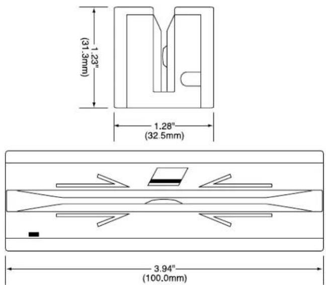
Table 1-1 lists the specifications for the USB Swipe Reader. Figure 1-2 shows the dimensions for the standard product.
Table 1-1. Specifications
| Reference Standards ISO 7810 and ISO 7811/AAMVA* |
| Power Input 5V From USB bus |
| Recording Method Two-frequency coherent phase (F2F) |
| Message Format ASCII |
| Card Speed 3 to 60 ips (7.62 – 152.4 cm/s) |
ELECTRICAL
| Current | |
| Normal | Mode5 mA |
| Suspend | Mode6 uA |
| MTBF 1.0 E06 Hrs based on Mil-217 | |
MECHANICAL
| SizeLengthWidthHeight | 3.94" (100.0mm)1.28" (32.5mm)1.23" (31.3mm) |
| Weight 4.5 oz. (127.57 g) | |
| Cable length 6 ft. (1.8m) | |
| Connector USB Type A plug | |
ENVIRONMENTAL
| Temperature | |
| Operating | °C to 70 °C (-40 °F to 158 °F) |
| Storage | °C to 70 °C (-40 °F to 158 °F) |
| Humidity | |
| Operating 10% to 90% noncondensing | |
| Storage 10% to 90% noncondensing | |
| Altitude | |
| Operating | 0-10,000 ft. (0-3048 m.) |
| Storage 0-50,000 ft. (0-15240 m.) | |
ISO (International Standards Organization) and AAMVA (American Association of Motor Vehicle Administrators).
text_image
(31.3mm) 1.23" (32.5mm) 1.28" 3.94" (100.0mm)Figure 1-2. Dimensions
SECTION 2. INSTALLATION
This section describes the cable connection, the Windows Plug and Play Setup, and the physical mounting of the unit.
USB CONNECTION
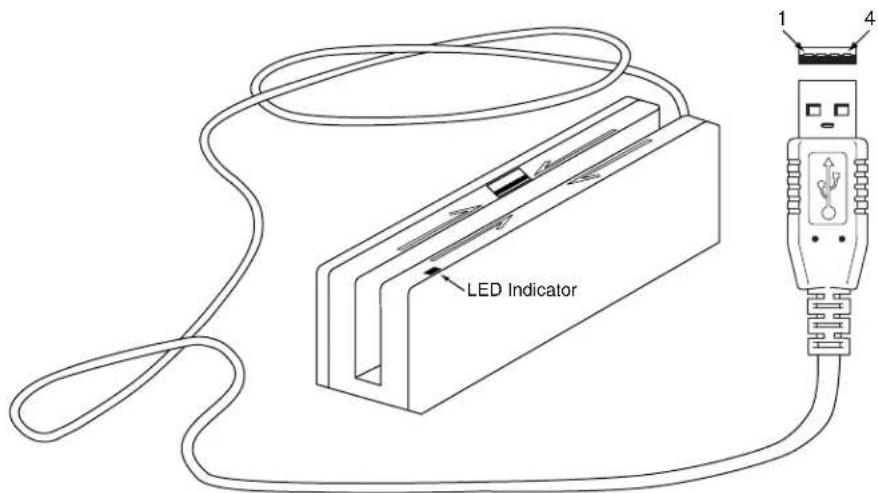
Connect the USB cable to a USB port on the host. The Reader, LED Indicator, and pin numbers for the 4-pin connector are shown in Figure 2-1.
text_image
LED Indicator 1 4Figure 2-1. Reader Cable and Connector
Pin numbers and signal descriptions for the cable shown in the illustration are listed in Table 2-1.
Table 2-1. 4-Pin Connector
| Pin Number | Signal Cable Color | |
| 1 | VBUS | Red |
| 2 | -Data | White |
| 3 | +Data | Green |
| 4 | Ground | Black |
WINDOWS PLUG AND PLAY SETUP
On hosts with the Windows operating system, the first time the device is plugged into a specific USB port, Windows will pop up a dialog box, which will guide you through the process of installing a device driver for the device. After this process is completed once, Windows will no longer request this process as long as the device is plugged into the same USB port. The device driver that Windows will install for this device is the driver used for HID devices and it is part of the Windows operating system. When the dialog box pops up, follow the instructions given in the dialog box. Sometimes Windows will find all the files it needs on its own without giving any prompts. Other times Windows will need to know the location of the files it needs. If Windows prompts for the file locations, insert the CD that was used to install Windows on your PC and point Windows to the root directory of the CD. Windows should find all the files it needs there.
MOUNTING
The Reader may be mounted with screws or fastening tape as described below.
Caution
The Reader should be mounted such that the bottom (mounting side) is not exposed to the user. This is because the mounting side of the reader may be susceptible to electrostatic discharge.
-
The Reader can be mounted on a surface in various ways:
-
By two screws through the surface attached to the bottom of the unit and running the cable on the top of the surface
- By two screws through the surface attached to the bottom of the unit and by drilling a hole in the surface for the cable and running the cable through the hole
- By attaching the unit to the surface with fastening tape and running the cable on the top of the surface
Note
The two mounting inserts are 3mm diameter, 0.5mm pitch, 6.4mm deep. The length of the screws used depends on the mounting surface thickness and the thickness of washers (if used).
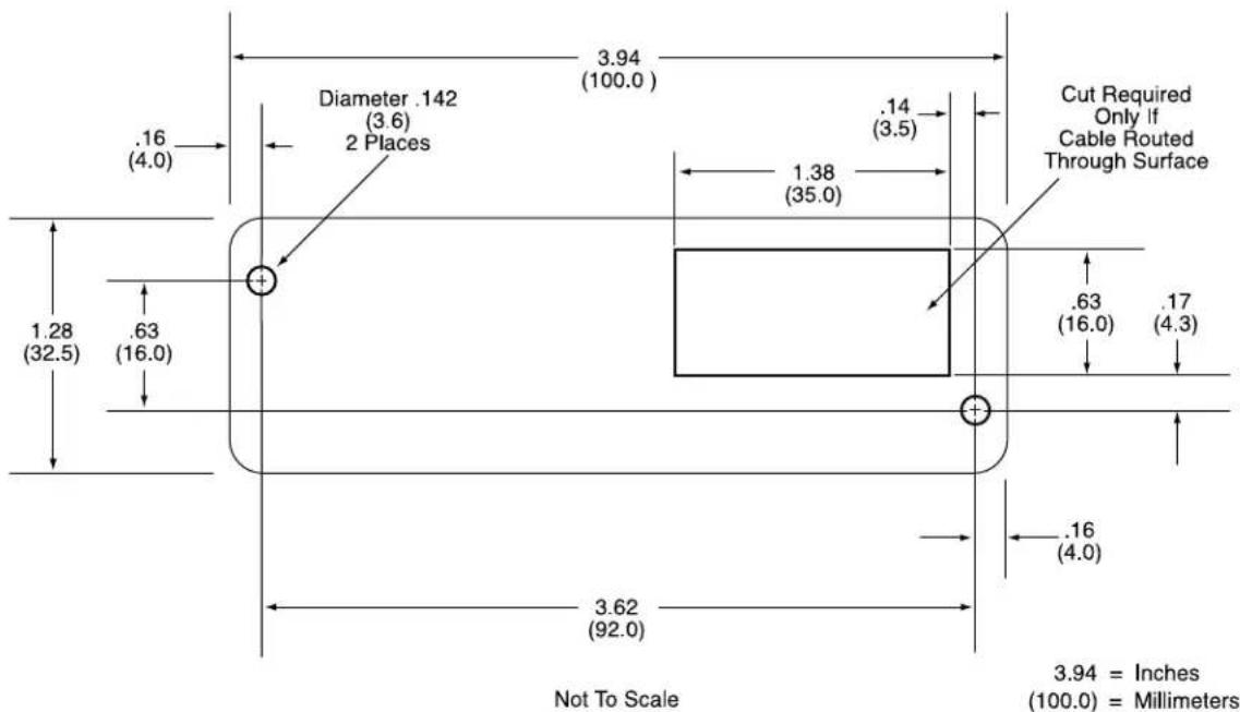
The mounting dimensions are shown in Figure 2-2. Determine the method of mounting required.
text_image
3.94 (100.0) .16 (4.0) Diameter .142 (3.6) 2 Places .14 (3.5) 1.38 (35.0) Cut Required Only If Cable Routed Through Surface .63 (16.0) .17 (4.3) 1.28 (32.5) .63 (16.0) 3.62 (92.0) .16 (4.0) 3.94 = Inches (100.0) = Millimeters Not To ScaleFigure 2-2. Mounting Hole Dimensions for Surface
- Ensure the Reader is positioned on a flat, accessible surface with at least 4 inches clearance on either end for room to swipe a card. Orient the Reader so the side with the LED is facing the direction of intended use.
If fastening tape is to be used, clean the area that the Reader will be mounted on with isopropyl alcohol. Remove the adhesive protective cover on the fastening tape, and position the Reader and push down firmly.
- Mount the Reader.
This section describes the LED Indicator and Card Read.
LED INDICATOR
The LED indicator will be either off, red, or green. When the device is not powered, the LED will be off. When the device is first plugged in, the LED will be red. As soon as the device is plugged in, the host will try to enumerate the device. Once the device is enumerated the LED will turn green indicating that the device is ready for use. When a card is being swiped, the LED will turn off temporarily until the swipe is completed. If there are no errors after decoding the card data then the LED will turn green. If there are any errors after decoding the card data, the LED will turn red for approximately two seconds to indicate that an error occurred and then turn green. Anytime the host puts the device into suspend mode, the LED will turn off. Once the host takes the device out of suspend mode, the LED will return to the state it was in prior to entering suspend mode.
CARD READ
A card may be swiped through the Reader slot when the LED is green.
When using a USB HID Swipe Reader (with a single head), the magnetic stripe must face toward the front (the side with the LED) and may be swiped in either direction.
When using a USB HID SureSwipe reader (with dual heads), the magnetic stripe can face toward the front or the back, and may be swiped in either direction.
If there is data encoded on the card, the reader will attempt to decode the data and then send the results to the host via a USB HID input report. After the results are sent to the host, the device will be ready to read the next card.
SECTION 4. USB COMMUNICATIONS
This device conforms to the USB specification revision 1.1. This device also conforms with the Human Interface Device (HID) class specification version 1.1. The device communicates to the host as a vendor-defined HID device. The details about how the card data and commands are structured into HID reports follow later in this section. The latest versions of the Windows operating systems come with a standard Windows USB HID driver. Windows applications that communicate to this device can be easily developed. These applications can communicate to the device using standard windows API calls that communicate to the device using the standard Windows USB HID driver. These applications can be easily developed using compilers such as Microsoft's Visual Basic or Visual C++. A demonstration program and its source code, written in Visual Basic, that communicates with this device is available. This demo program can be used to test the device and it can be used as a guide for developing other applications. More details about the demo program follow later in this document.
It is recommended that application software developers become familiar with the HID specification the USB specification before attempting to communicate with this device. This document assumes that the reader is familiar with these specifications. These specifications can be downloaded free from www.usb.org.
This is a full speed USB device. This device has a number of programmable configuration properties. These properties are stored in non-volatile memory. These properties can be configured at the factory or by the end user. The device has an adjustable endpoint descriptor polling interval value that can be set to any value in the range of 1ms to 255ms. This property can be used to speed up or slow down the card data transfer rate. The device also has an adjustable serial number descriptor. More details about these properties can be found later in this document in the command section.
The device will go into suspend mode when directed to do so by the host. The device will wakeup from suspend mode when directed to do so by the host. The device does not support remote wakeup.
This device is powered from the USB bus. Its vendor ID is 0x0801 and its product ID is 0x0002.
HID USAGES
HID devices send data in reports. Elements of data in a report are identified by unique identifiers called usages. The structure of the device's reports and the device's capabilities are reported to the host in a report descriptor. The host usually gets the report descriptor only once, right after the device is plugged in. The report descriptor usages identify the devices capabilities and report structures. For example, a device could be identified as a keyboard by analyzing the device's report descriptor. Usages are four byte integers. The most significant two bytes are called the usage page and the least significant two bytes are called usage IDs. Usages that are related can share a common usage page. Usages can be standardized or they can be vendor defined. Standardized usages such as usages for mice and keyboards can be found in the HID Usage Tables document and can be downloaded free at www.usb.org. Vendor-defined usages must have a usage page in the range 0xff00 – 0xffff. All usages for this device use vendor-defined magnetic stripe reader usage page 0xff00. The usage IDs for this device are defined in the
following table. The usage types are also listed. These usage types are defined in the HID Usage Tables document.
Magnetic Stripe Reader usage page 0xff00:
| Usage ID (Hex) | Usage Name Usage Type | Type | Report Type |
| 1 Decoding reader device Collection None | |||
| 20 Track 1 decode status Data Input | |||
| 21 Track 2 decode status Data Input | |||
| 22 Track 3 decode status Data Input | |||
| 28 Track 1 data length Data Input | |||
| 29 Track 2 data length Data Input | |||
| 2A Track 3 data length Data Input | |||
| 30 Track 1 data Data Input | |||
| 31 Track 2 data Data Input | |||
| 32 Track 3 data Data Input | |||
| 38 Card encode type Data Input | |||
| 20 Command message Data | |||
Feature
REPORT DESCRIPTOR
The HID report descriptor is structured as follows:
| Item | Value (Hex) |
| Usage Page (Magnetic Stripe Reader) 06 00 FF | |
| Usage (Decoding reader device) 09 01 | |
| Collection (Application) | A1 01 |
| Logical Minimum (0) | 15 00 |
| Logical Maximum (255) | 26 FF 00 |
| Report Size (8) | 75 08 |
| Usage (Track 1 decode status) | 09 20 |
| Usage (Track 2 decode status) | 09 21 |
| Usage (Track 3 decode status) | 09 22 |
| Usage (Track 1 data length) | 09 28 |
| Usage (Track 2 data length) | 09 29 |
| Usage (Track 3 data length) | 09 2A |
| Usage (Card encode type) | 09 38 |
| Report Count (7) | 95 07 |
| Input (Data, Variable, Absolute, Bit Field) | 81 02 |
| Usage (Track 1 data) | 09 30 |
| Report Count (110) | 95 6E |
| Input (Data, Variable, Absolute, Buffered Bytes) | 82 02 01 |
| Usage (Track 2 data) | 09 31 |
| Report Count (110) | 95 6E |
| Input (Data, Variable, Absolute, Buffered Bytes) | 82 02 01 |
| Usage (Track 3 data) | 09 32 |
| Report Count (110) | 95 6E |
| Input (Data, Variable, Absolute, Buffered Bytes) | 82 02 01 |
| Usage (Command message) 09 20 | |
| Report Count (24) 95 18 | |
| Feature (Data, Variable, Absolute, Buffered Bytes) B2 02 01 | |
| End Collection C0 | |
CARD DATA
Card data is only sent to the host on the Interrupt In pipe using an Input Report. The device will send only one Input Report per card swipe. If the host requests data from the device when no data is available, the device will send a Nak to the host to indicate that it has nothing to send. When a card is swiped, the Input Report will be sent even if the data is not decodable. The following table shows how the input report is structured.
| Offset | Usage Name |
| 0 Track 1 decode status | |
| 1 Track 2 decode status | |
| 2 Track 3 decode status | |
| 3 Track 1 data length | |
| 4 Track 2 data length | |
| 5 Track 3 data length | |
| 6 Card encode type | |
| 7 – 116 Track 1 data | |
| 117 – 226 Track 2 data | |
| 227 - 336 Track 3 data | |
TRACK 1 DECODE STATUS
| Bits | 7-1 | 0 |
| Value | Reserved | Error |
This is a one-byte value, which indicates the status of decoding track 1. Bit position zero indicates if there was an error decoding track 1 if the bit is set to one. If it is zero, then no error occurred. If a track has data on it that is not noise, and it is not decodable, then a decode error is indicated. If a decode error is indicated, the corresponding track data length value for the track that has the error will be set to zero and no valid track data will be supplied.
TRACK 2 DECODE STATUS
| Bits | 7-1 | 0 |
| Value | Reserved | Error |
This is a one-byte value, which indicates the status of decoding track 2. Bit position zero indicates if there was an error decoding track 2 if this bit is set to one. If it is zero, then no error occurred. If a track has data on it that is not noise, and it is not decodable, then a decode error is indicated. If a decode error is indicated, the corresponding track data length value for the track that has the error will be set to zero and no valid track data will be supplied.
TRACK 3 DECODE STATUS
| Bits | 7-1 | 0 |
| Value | Reserved | Error |
This is a one-byte value, which indicates the status of decoding track 3. Bit position zero indicates if there was an error decoding track 3 if this bit is set to one. If it is zero, then no error occurred. If a track has data on it that is not noise, and it is not decodable, then a decode error is indicated. If a decode error is indicated, the corresponding track data length value for the track that has the error will be set to zero and no valid track data will be supplied.
TRACK 1 DATA LENGTH
This one-byte value indicates how many bytes of decoded card data are in the track 1 data field. This value will be zero if there was no data on the track or if there was an error decoding the track.
TRACK 2 DATA LENGTH
This one-byte value indicates how many bytes of decoded card data are in the track 2 data field. This value will be zero if there was no data on the track or if there was an error decoding the track.
TRACK 3 DATA LENGTH
This one-byte value indicates how many bytes of decoded card data are in the track 3 data field. This value will be zero if there was no data on the track or if there was an error decoding the track.
CARD ENCODE TYPE
This one-byte value indicates the type of encoding that was found on the card. The following table defines the possible values.
| Value | Encode Type | Description |
| 0 ISO/ABA ISO/ABA encode format | ||
| 1 AAMVA AAMVA encode format | ||
| 2 CADL CADL encode format. | Note that (after the June 2005 update) this reader can only read track 2 for this format. It cannot read tracks 1 and 3. However, this format is obsolete. There should no longer be any cards in circulation that use this format. California is now using the AAMVA format. | |
| 3 Blank The card is blank. | ||
| 4 Other The card has a non-standard encode format. For example, ISO/ABA track 1 format on track 2. | ||
| 5 Undetermined The card encode type could not be determined because no tracks could be decoded. | ||
| 6 None No decode has occurred. This type occurs if no magnetic stripe data has been acquired since the data has been cleared or since the device was powered on. This device only sends an Input report when a card has been swiped so this value will never occur. | ||
TRACK DATA
If decodable track data exists for a given track, it is located in the track data field that corresponds to the track number. The length of each track data field is fixed at 110 bytes, but the length of valid data in each field is determined by the track data length field that corresponds to the track number. Track data located in positions greater than the track data length field indicates are undefined and should be ignored. The HID specification requires that reports be fixed in size, but the number of bytes encoded on a card may vary. Therefore, the Input Report always contains the maximum amount of bytes that can be encoded on the card and the number of valid bytes in each track is indicated by the track data length field. The track data is decoded and converted to ASCII. The track data includes all data starting with the start sentinel and ending with the end sentinel.
TRACK 1 DATA
This field contains the decoded track data for track 1.
TRACK 2 DATA
This field contains the decoded track data for track 2.
TRACK 3 DATA
This field contains the decoded track data for track 3.
COMMANDS
Most host applications do not need to send commands to the device. Most host applications only need to obtain card data from the device as described previously in this section. This section of the manual can be ignored by anyone who does not need to send commands to the device.
Command requests and responses are sent to and received from the device using feature reports. Command requests are sent to the device using the HID class specific request Set_Report. The response to a command is retrieved from the device using the HID class specific request Get_Report. These requests are sent over the default control pipe. When a command request is sent, the device will Nak the Status stage of the Set_Report request until the command is completed. This insures that, as soon as the Set_Report request is completed, the Get_Report request can be sent to get the command response. The usage ID for the command message was shown previously in the Usage Table.
The following table shows how the feature report is structured for command requests:
| Offset | Field | Name |
| 0 | Command | Number Length |
| 1 | Data | |
| 2 – 23 Data |
The following table shows how the feature report is structured for command responses.
| Offset | Field | Name |
| 0 | Result | Code Length |
| 1 | Data | |
| 2 – 23 Data |
COMMAND NUMBER
This one-byte field contains the value of the requested command number. The following table lists all the existing commands.
| Value | Command Number | Description |
| 0 GET PROPERTY Gets a property from the device | ||
| 1 SET PROPERTY Sets a property in the device | ||
| 2 RESET_DEVICE Resets the device | ||
DATA LENGTH
This one-byte field contains the length of the valid data contained in the Data field.
DATA
This multi-byte field contains command data if any. Note that the length of this field is fixed at 22 bytes. Valid data should be placed in the field starting at offset 2. Any remaining data after the valid data should be set to zero. This entire field must always be set even if there is no valid data. The HID specification requires that Reports be fixed in length. Command data may vary in length. Therefore, the Report should be filled with zeros after the valid data.
RESULT CODE
This one-byte field contains the value of the result code. There are two types of result codes: generic result codes and command-specific result codes. Generic result codes always have the most significant bit set to zero. Generic result codes have the same meaning for all commands and can be used by any command. Command-specific result codes always have the most significant bit set to one. Command-specific result codes are defined by the command that uses them. The same code can have different meanings for different commands. Command-specific result codes are defined in the documentation for the command that uses them. Generic result codes are defined in the following table.
| Value | Result Code | Description |
| 0 SUCC | ESS The command completed successfully. | |
| 1 FAILURE | The command failed. | |
| 2 BAD_PARAMETER | The command failed due to a bad parameter or command syntax error. | |
GET AND SET PROPERTY COMMANDS
The Get Property command gets a property from the device. The Get Property command number is 0.
The Set Property command sets a property in the device. The Set Property command number is 1.
The Get and Set Property command data fields for the requests and responses are structured as follows:
Get Property Request Data:
| Data Offset Value | |
| 0 | Property |
ID
Get Property Response Data:
| Data Offset Value | |
| 0 – n Property Value |
Set Property Request Data:
| Data Offset Value | |
| 0 | Property |
| 1 – n Property Value |
ID
Set Property Response Data:
None
The result codes for the Get and Set Property commands can be any of the codes list in the generic result code table.
Property ID is a one-byte field that contains a value that identifies the property. The following table lists all the current property ID values:
| Value | Property ID | Description |
| 0 | SOFTWARE_ID | The device's software identifier |
| 1 | SERIAL_NUM | The device's serial number |
| 2 | POLLING_INTERVAL | The interrupt pipe's polling interval |
| 3 | MAX_PACKET_SIZE | The interrupt pipe's packet size |
| 4 | TRACK_ID_ENABLE | Allows tracks to be disabled |
| 16 | INTERFACE_TYPE | Type of USB interface |
The Property Value is a multiple-byte field that contains the value of the property. The number of bytes in this field depends on the type of property and the length of the property. The following table lists all of the property types and describes them.
| Property Type | Description |
| Byte This is a one-byte value. The valid values depend on the property. | |
| String | This is a multiple-byte ASCII string. Its length can be zero to a maximum length that depends on the property. The value and length of the string does not include a terminating NUL character. |
SOFTWARE\_ID PROPERTY
Property ID: 0
Property Type: String
Length: Fixed at 11 bytes
Get Property: Yes
Set Property: No
Description: This is an 11-byte read only property that identifies the software part number and version for the device. The first 8 bytes represent the part number and the last 3 bytes represent the version. For example this string might be “21042812D01”. Examples follow:
Example Get SOFTWARE_ID property Request (Hex):
| Cmd Num Data Len Prp ID | ||
| 00 | 01 | 00 |
Example Get SOFTWARE_ID property Response (Hex):
| Result Code | Data Len Prp | Value | ||||
| 00 | 01 | 32 | 31 | 30 | 34 | 32 38 31 |
SERIAL\_NUM PROPERTY
Property ID: 1
Property Type: String
Length: 0 - 15 bytes
Get Property: Yes
Set Property: Yes
Default Value: The default value is no string with a length of zero.
Description: The value is an ASCII string that represents the device's serial number. This string can be 0 - 15 bytes long. The value of this property, if any, will be sent to the host when the host requests the USB string descriptor.
This property is stored in non-volatile memory, so it will persist when the unit is power cycled. When this property is changed, the unit must be reset (see Command Number 2) or power cycled to have these changes take effect.
Example Set SERIAL_NUM property Request (Hex):
| Cmd Num Data Len Prp ID Prp Value | ||||||
| 01 | 04 | 01 | 31 | 32 | 33 | |
Example Set SERIAL_NUM property Response (Hex):
| Result Code | Data Len | Data |
| 00 | 00 |
Example Get SERIAL_NUM property Request (Hex):
| Cmd Num Data Len Prp ID | ||
| 00 | 01 | 01 |
Example Get SERIAL_NUM property Response (Hex):
| Result Code | Data Len | Prp | Value |
| 00 03 31 32 $3 | |||
POLLING\_INTERVAL PROPERTY
Property ID: 2
Property Type: Byte
Length: 1 byte
Get Property: Yes
Set Property: Yes
Default Value: 10
Description: The value is a byte that represents the devices polling interval for the Interrupt In Endpoint. The value can be set in the range of 1 – 255 and has units of milliseconds. The polling interval tells the host how often to poll the device
for card data packets. For example, if the polling interval is set to 10, the host will poll the device for card data packets every 10ms. This property can be used to speed up or slow down the time it takes to send card data to the host. The trade-off is that speeding up the card data transfer rate increases the USB bus bandwidth used by the device, and slowing down the card data transfer rate decreases the USB bus bandwidth used by the device. The value of this property, if any, will be sent to the host when the host requests the device's USB endpoint descriptor.
This property is stored in non-volatile memory, so it will persist when the unit is power cycled. When this property is changed, the unit must be reset (see Command Number 2) or power cycled to have these changes take effect.
Example Set POLLING_INTERVAL property Request (Hex):
| Cmd Num | Data Len | Prp ID | Prp Value | |
| 01 | 02 | 02 | 0A | |
Example Set POLLING_INTERVAL property Response (Hex):
| Result Code | Data Len Data | |
| 00 | 00 | |
Example Get POLLING_INTERVAL property Request (Hex):
| Cmd Num Data Len Prp ID | ||
| 00 | 01 | 02 |
Example Get POLLING_INTERVAL property Response (Hex):
| Result Code | Data Len Prp | Value |
| 00 | 01 | 0A |
MAX\_PACKET\_SIZE PROPERTY
Property ID: 3
Property Type: Byte
Length: 1 byte
Get Property: Yes
Set Property: Yes
Default Value: 8
Description: The value is a byte that represents the devices maximum packet size for the Interrupt In Endpoint. The value can be set in the range of 1 – 64 and has units of bytes. The maximum packet size tells the host the maximum size of the Interrupt In Endpoint packets. For example, if the maximum packet size is set to 8, the device will send HID reports in multiple packets of 8 bytes each or less for the last packet of the report. This property can be used to speed up or slow down the time it takes to send card data to the host. Larger packet sizes speed up communications and smaller packet sizes slow down communications. The trade-off is that speeding up the card data transfer rate increases the USB bus bandwidth used by the device, and slowing down the card data transfer rate decreases the USB bus bandwidth used by the device. The value of this property will be sent to the host when the host requests the device's USB endpoint descriptor.
This property is stored in non-volatile memory, so it will persist when the unit is power cycled. When this property is changed, the unit must be reset (see Command Number 2) or power cycled to have these changes take effect.
Example Set MAX_PACKET_SIZE property Request (Hex):
| Cmd Num | Data Len | Prp ID | Prp Value | |
| 01 | 02 | 03 | 08 | |
Example Set MAX_PACKET_SIZE property Response (Hex):
| Result Code | Data Len Data | |
| 00 | 00 | |
Example Get MAX_PACKET_SIZE property Request (Hex):
| Cmd Num | Data Len | Prp ID |
| 00 | 01 | 03 |
Example Get MAX_PACKET_SIZE property Response (Hex):
| Result Code | Data Len Prp | Value |
| 00 | 01 | 08 |
TRACK\_ID\_ENABLE PROPERTY
Property ID: 4
Property Type: Byte
Length: 1 byte
Get Property: Yes
Set Property: Yes
Default Value: 95 (hex)
Description: This property is defined as follows:
| id | 0 | T_3 | T_3 | T_2 | T_2 | T_1 | T_1 |
Id 0 – Decodes standard ISO/ABA cards only
1 - Decodes AAMV and 7-bit cards also
T# 00 - Track Disabled
01 - Track Enabled
10 - Track Enabled/Required (Error if blank)
This property is stored in non-volatile memory, so it will persist when the unit is power cycled. When this property is changed, the unit must be reset (see Command Number 2) or power cycled to have these changes take effect.
Example Set TRACK_ID_ENABLE property Request (Hex):
| Cmd Num | Data Len | Prp ID | Prp Value | |
| 01 | 02 | 04 | 95 |
Example Set TRACK_ID_ENABLE property Response (Hex):
| Result Code | Data Len Data | |
| 00 | 00 | |
Example Get TRACK_ID_ENABLE property Request (Hex):
| Cmd Num Data Len Prp ID | ||
| 00 | 01 | 04 |
Example Get TRACK_ID_ENABLE property Response (Hex):
| Result Code | Data Len Prp | Value |
| 00 | 01 | 95 |
INTERFACE\_TYPE PROPERTY
Property ID: 16 (10 hex)
Property Type: Byte
Length: 1 byte
Get Property: Yes
Set Property: Yes
Default Value: 0 (HID)
Description: The value is a byte that represents the devices interface type. The value can be set to 0 for the HID interface or to 1 for the keyboard emulation interface. When the value is set to 0 (HID) the device will behave as described in the HID manual. When the value is set to 1 (keyboard emulation) the device will behave as described in the keyboard emulation manual. This property should be the first property changed because it affects which other properties are available. After this property is changed, the device should be power cycled before changing any other properties.
This property is stored in non-volatile memory, so it will persist when the unit is power cycled. When this property is changed, the unit must be reset (see Command Number 2) or power cycled to have these changes take effect.
Example Set INTERFACE_TYPE property Request (Hex):
| Cmd Num | Data Len | Prp ID | Prp Value | |
| 01 | 02 | 10 | 01 |
Example Set INTERFACE_TYPE property Response (Hex):
| Result Code | Data Len Data | |
| 00 | 00 | |
Example Get INTERFACE_TYPE property Request (Hex):
| Cmd Num Data Len Prp ID | ||
| 00 | 01 | 10 |
Example Get INTERFACE_TYPE property Response (Hex):
| Result Code | Data Len Prp | Value |
| 00 | 01 | 00 |
RESET\_DEVICE COMMAND
Command number: 2
Description: This command is used to reset the device. This command can be used to make previously changed properties take affect without having to unplug and then plug in the device. When the device resets, it automatically does a USB detach followed by an attach. After the host sends this command to the device it should close the USB port, wait a few seconds for the operating system to handle the device detach followed by the attach and then re-open the USB port before trying to communicate further with the device.
Data structure: No data is sent with this command
Result codes: 0 (success)
Example Request (Hex):
| Cmd Num Data Len Data | ||
| 02 | 00 | |
Example Response (Hex):
| Result Code | Data Len | Data |
| 00 | 00 |
SECTION 5. DEMO PROGRAM
The demo program, which is written in Visual Basic, can be used to do the following:
- Read cards from the device and view the card data
- Send command requests to the device and view the command responses
- Guide application developers in their application development by providing examples, in source code, of how to properly communicate with the device using the standard Windows APIs
The part numbers for the demo program can be found in this document in Section 1 under Accessories.
INSTALLATION
To install the demo program, run the setup.exe file and follow the instructions given on the screen.
OPERATION
To operate the demo program perform the following steps:
- Attach the device into a USB port on the host.
- If this is the first time the device has been plugged into the host, follow the instructions on the screen for installing the Windows HID device driver. This is explained in more detail in the installation section of this document.
- Run the demo program.
- To read cards and view the card data, click on the Read Cards button and swipe a card when prompted to do so.
- When finished reading cards, close the dialog box.
- To send commands to the device, click on the send commands button.
- Enter a command in the Message edit box. All data entered should be in hexadecimal bytes with a space between each byte. Enter the command number followed by the command data if there is any. The application will automatically calculate and send the command data length for you. For example, to send the GET_PROPERTY command for property SOFTWARE_ID enter 00 00.
- Press Enter or click on Send message to send the command and receive the result.
- The command request and the command result will be displayed in the Communications Dialog edit box.
- The Clear Dialog button clears the Communication Dialog edit box.
SOURCE CODE
Source code is included with the demo program. It can be used as a guide for application development. It is described in detail, with comments, to assist developers. The book USB Complete by Jan Axelson is also a good guide for application developers, especially the chapter on Human Interface Device Host Applications (see “Reference Documents” in Section 1).