Discus DRG A124G - Router Pirelli - Free user manual and instructions
Find the device manual for free Discus DRG A124G Pirelli in PDF.


User questions about Discus DRG A124G Pirelli
0 question about this device. Answer the ones you know or ask your own.
Ask a new question about this device
Download the instructions for your Router in PDF format for free! Find your manual Discus DRG A124G - Pirelli and take your electronic device back in hand. On this page are published all the documents necessary for the use of your device. Discus DRG A124G by Pirelli.
USER MANUAL Discus DRG A124G Pirelli
Multiplay Access Gateway Family
natural_image
Illustration of a white INFOSTRADA router with a man standing on a platform, standing by water, and a woman standing on a platform in the background (no text or symbols on the router itself)User Manual
Discus™ DRG A124G
Copyright © 2008 Pirelli Broadband Solutions S.p.A. All rights reserved. This document contains Pirelli proprietary and confidential information. No part of this document may be copied, reprinted or reproduced in any material form or electronically, whether wholly or in part, and no information contained herein may be used or disclosed to third parties unless under a previous written agreement with Pirelli Broadband Solutions S.p.A setting forth relevant terms and conditions.
Trademarks:
All terms used in this document that are known to be trademarks or service marks have been noted as such. Pirelli cannot attest to the accuracy of this information. Other product and corporate names used in this document that may be trademarks or service marks of other companies are used only for explanation and to the owner's benefit, without intent to infringe. Use of a term in this document should not be regarded as affecting the validity of any trademark or service mark.
This publication is subject to change without notice. Pirelli reserves the right to make changes to equipment design and system components as well as system documentation and literature as progress in engineering, manufacturing methods, or other circumstances may warrant.
This publication is intended solely for informational and instructional purposes. Refer to the above as to its possible uses. It constitutes neither a contract with the user hereof nor a warranty or guarantee with regard to any of the Pirelli products described herein nor shall it be construed to grant a license or any other rights under any proprietary rights to information or material included herein. Pirelli hereby expressly disclaims any warranty or guarantee, whether express or implied, with regard to items described herein. Any contract, license, or warranty between Pirelli and the user hereof is created solely by separate legal documents.
Manual Code: OGU 930500195-A1
DISCUS™ DRG A124G
CONTENTS
Welcome 1
About this Guide 1
Naming Convention 1
Conventions 1
Introduction 3
Introduction 3
Package Contents 3
Router Advantages 5
Applications 5
Hardware Description 6
Minimum System and Component Requirements 6
Front Panel 6
Rear Panel 8
Hardware Installation 9
ISP Settings 9
Positioning the Router 10
Installing Micro Filters 10
Powering up the Router 11
Connecting the Router 11
Install Software 13
Ethernet Connection 13
TCP/IP configuration 13
Ethernet Connection >> TCP/IP Protocol Installation 14
Ethernet Connection >> MS Windows 98SE, ME, 2000 14
Ethernet Connection >> MS Windows XP 16
Disable HTTP Proxy 17
Obtain IP settings from Router >> MS Windows 98SE, ME, 2000 17
Obtain IP settings from Router >> MS Windows XP 19
Ethernet Connection >> MAC OS 10.X 19
Wi-Fi Connection 20
Router Configuration 23
Management Interface 24
© (2008) Pirelli Broadband Solutions S.p.A. All Rights Reserved. Proprietary Use Pursuant to Cover Page Instructions.
DISCUS™ DRG A124G
Making configuration changes 24 Advanced Configuration Parameters 24
System Section 27
system >> time settings 27 system >> password settings 28 system >> DNS 28
WAN Section 31
WAN >> ATM pvc 31 WAN >> ATM interface 1483 bridging 32 WAN >> ATM Interface PPPoA 33 WAN >> ATM Interface 1483 routing 35 WAN >> ATM Interface PPPoE 36 WAN >> ATM Interface MAC Encapsulated Routing 38 WAN >> Clone MAC Address 39
LAN Section 41
LAN >> VLAN 42
Wireless Section 45
Wireless >> Channel and SSID 45 Wireless >> Access Control 46 Wireless >> Security 47 Wireless >> Security >> WEP 47 Wireless >> Security >> WPA 49 Wireless >> Security >> 802.1X 49 Wireless >> Wi-Fi Protected Setup 50 Wireless >> WDS 51 Wireless >> Advanced Setting 52
NAT Section 55
NAT >> Address Mapping 55 NAT >> Virtual Server 56 NAT >> Special Application 57 NAT >> NAT Mapping Table 58
Routing Section 61
Routing >> Static Route 61
© (2008) Pirelli Broadband Solutions S.p.A. All Rights Reserved. Proprietary Use Pursuant to Cover Page Instructions.
DISCUS™ DRG A124G
Routing >> RIP 62
Routing >>Routing Table 64
Firewall Section 67
Firewall >> Access Control 68
Firewall >> MAC Filter 69
Firewall >> URL Blocking 70
Firewall >> Schedule Rule 70
Firewall >> Intrusion Detection 71
Firewall >> DMZ 75
SNMP Section 77
SNMP >> Community 77
SNMP >> Trap 78
UPnP Section 81
QoS Section 83
QoS >> Traffic Mapping 84
QoS >> Traffic Statistics 85
ADSL Section 87
ADSL >> Parameters 87
ADSL >> Status 88
DDNS Section 91
Tools Section 93
Tools >> Configuration Tools 93
Tools >> Firmware Upgrade 94
Tools >> Reset 94
Status Section 95
Safety Information 99
IP Addressing 101
© (2008) Pirelli Broadband Solutions S.p.A. All Rights Reserved. Proprietary Use Pursuant to Cover Page Instructions.
DISCUS™ DRG A124G
Technical Specifications 103 Glossary 107
© (2008) Pirelli Broadband Solutions S.p.A. All Rights Reserved. Proprietary Use Pursuant to Cover Page Instructions.
Welcome
ABOUT THIS GUIDE
This guide describes how to install and configure the DISCUS™ DRG A124G. This guide is intended for use by those responsible for installing and setting up network equipment; consequently, it assumes a basic working knowledge of LANs (Local Area Networks) and Internet Routers.
NAMING CONVENTION
Throughout this guide, the DISCUS™ DRG A124G is referred to as the "Wireless Router". Category 5 Ethernet Cables are referred to as Ethernet Cables throughout this guide.
CONVENTIONS
Table 1. and Table 2. list conventions that are used throughout this guide.
TABLE 1. Notice Icons
| Icon | Notice | Type | Description |
| Information note | Information that describes important features or instructions. | ||
 | Caution | Information that alerts you to potential loss of data or potential damage to an application, system, or device. | |
© (2008) Pirelli Broadband Solutions S.p.A. All Rights Reserved. Proprietary Use Pursuant to Cover Page Instructions.
TABLE 1. Notice Icons
| Icon | Notice | Type | Description |
 | Warning | Information that alerts you to potential personal injury. | |
TABLE 2. Text Conventions
| Convention | Description |
| The words “enter” and “type” | When you see the word “enter” in this guide, you must type something, and then press Return or Enter. Do not press Return or Enter when an instruction simply says “type.” |
| Keyboard key names If you must press two or more keys simultaneously, the key names are linked with a plus sign (+). Example:Press Ctrl+Alt+Del | |
| Words in italics Italics are used to:Emphasize a point.Identify a voice on the menu. | |
| Words in bold Bold is used to:Identify a button command menu (e.g. Click OK button). | |
| Words in bold+italics This combo is used to:Identify a path that brings to one command menu (e.g. Statistics->LAN).Identify a command menu (e.g. Summary menu) | |
© (2008) Pirelli Broadband Solutions S.p.A. All Rights Reserved. Proprietary Use Pursuant to Cover Page Instructions.
Introduction
INTRODUCTION
The DISCUS™ DRG A124G is designed to provide a cost-effective mean of sharing a single broadband Internet connection between several wired and wireless computers. The Router also provides protection in the form of an electronic "firewall" preventing anyone outside of your network from seeing your files or damaging your computers.
The DISCUS™ DRG A124G is an ADSL2+ router, targeted to residential environments and SOHO customers, that provides routed broadband services from a single and modular access point.
The DISCUS™ DRG A124G is the ideal solution for:
- Connecting multiple PCs and Video game consoles;
- Sharing broadband internet connections with all home computers;
- Sharing printers and peripherals;
PACKAGE CONTENTS
Your new DISCUS™ DRG A124G ADSL2+ Router kit contains the related hardware and software. In it you will find:
- One DISCUS™ DRG A124G unit
- One Switching Power Supply adapter
- One Telephone patch cable with RJ-11 plug
- One Ethernet CAT5 cable with RJ-45 plug
- A CD-ROM containing:
a. USB Driver
b. User Manual
© (2008) Pirelli Broadband Solutions S.p.A. All Rights Reserved. Proprietary Use Pursuant to Cover Page Instructions.
DISCUS™ DRG A124G
c. Quick Installation Guide
d. Smart Setup Configuration Utility
TABLE 1. Kit Material
| Quantity | DESCRIPTION | |
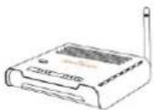 | 1 | DISCUS ^TM DRG A124G |
 | 1 | Switching Power Supplier Adapter |
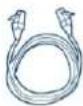 | 1 | Ethernet Cable |
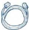 | 1 | Telephone patch cable |
 | 1 | CD-ROM |
If any of the items included in the package is damaged, please contact your Service Provider.
It implements an high speed Asymmetric Digital Subscriber Line (ADSL2/2+) connection to the telephone line on the WAN side, as well as several local connectivity technologies on the LAN side:
• Four switched 10/100 Base-TX Ethernet ports
• A Wi-Fi connection to hosts devices
Figure 1 shows a sample network: your Router becomes your connection to the Internet. Connections can be made directly to the Router expanding the number of computers you can have in your network.
DISCUS™ DRG A124G
FIGURE 1. Sample Home Network
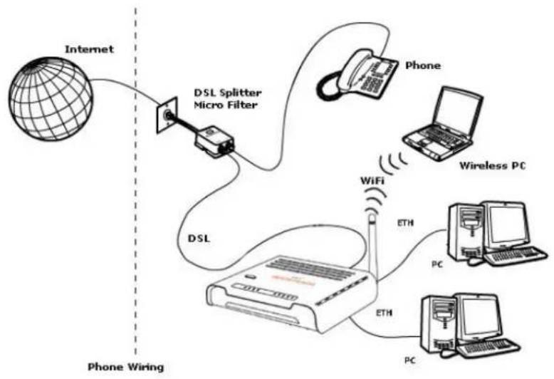
flowchart
graph TD
    A["Internet"] --> B["DSL Splitter Micro Filter"]
    B --> C["Phone"]
    C --> D["Wireless PC"]
    D --> E["PC"]
    E --> F["ETH"]
    F --> G["WiFi"]
    G --> H["DSL"]
    H --> I["Phone Wiring"]
    style A fill:#f9f,stroke:#333
    style B fill:#ccf,stroke:#333
    style C fill:#cfc,stroke:#333
    style D fill:#fcc,stroke:#333
    style E fill:#cff,stroke:#333
    style F fill:#ffc,stroke:#333
    style G fill:#cfc,stroke:#333
    style H fill:#fcc,stroke:#333
    style I fill:#ffc,stroke:#333
ROUTER ADVANTAGES
The advantages of the DISCUS™ DRG A124G include:
- Shared Internet connection for both wired and wireless computers
• High speed 802.11b/g wireless networking - Cross-platform operation for compatibility with Microsoft® Windows, Linux and Apple® MAC computers
- Easy-to-use, Web-based setup and configuration
• Centralization of all network address settings (DHCP) - A Virtual server to enable remote access to Web, FTP, and other services on your network
- A Security - Firewall protection - against Internet hacker attacks and encryption to protect wireless network traffic
• A multi-language GUI.
APPLICATIONS
Many advantages networking features are provided by the DISCUS™ DRG A124G:
- Wireless and Wired LAN: the router provides connectivity to 10/100 Mbps devices, and wireless IEEE 802.11b/g compatible devices, making it easy to create a network in small offices or homes.
- Internet Access: this device supports Internet access through an ADSL connection. Since many DSL providers use PPPoE or PPPoA to establish communications with end users, the Router includes built-in clients for these protocols, eliminating the need to install these services on your computer.
DISCUS™ DRG A124G
HARDWARE DESCRIPTION
The Router contains an integrated ADSL modem and connects to the Internet or to a remote site through the ADSL (RJ11) port. It can be connected directly through your PCs or to a local area network using the four Fast Ethernet LAN ports.
Access speed to the Internet depends on your service type. Full rate ADSL provides up to 8 Mbps downstream and 1 Mbps upstream. G.lite (or splitterless) ADSL provides up to 1.5 Mbps downstream and 512 kbps upstream. However, you should note that the actual rate provided by specific service providers may vary dramatically from these upper limits.
Data passing between devices connected to your local area network can run at up to 100 Mbps over the Fast Ethernet ports and 54 Mbps over the built-in wireless access point.
MINIMUM SYSTEM AND COMPONENT REQUIREMENTS
Your Router requires the computer(s) and components in your network to be configured with at least the following:
- A computer with the Operating Systems that support TCP/IP networking protocols: Microsoft® Windows 98SE, Windows ME, Windows 2000, Windows XP 32bit, Vista 32bit or Apple® MAC 10.x or Linux
- Internet access account from your Internet Service Provider (ISP)
- A PC using a dynamic IP address assigned via DHCP, as well as a gateway server address and DNS server address from your service provider
- A PC equipped with 10/100 Mbps Fast Ethernet adapter
- TCP/IP networks protocols installed on each PC that will access the Internet
- A Java-enabled web browser, such as Microsoft Internet Explorer 6.0 or above, Mozilla Firefox 2.0 or Above installed on one PC at your site for configuring the Router
FRONT PANEL
The front panel of the Router contains six indicator lights (LEDs) that help to describe the state of networking and connection operations.
DISCUS™ DRG A124G
FIGURE 2. Front Panel LEDs
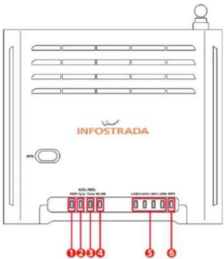
text_image
INFOSTRADA WPS ADSL APEL PRS Type: Data WLSN LANLAN/LAN1/LAN2 WPS ① ② ③ ④ ⑤ ⑥TABLE 2. LED Description
| Ref. | LED | LED Colour | LED Description | |
| 1 | Power | Green/Red | On | Power on |
| Off | Power off or failure | |||
| 2 | ADSL Sync | Green | On | ADSL connection is functioning correctly |
| Flashing | Startup | |||
| Off | No ADSL connection established | |||
| 3 | ADSL Data | Green | Flashing | The ADSL port is sending or receiving data |
| Off | No data is being transferred | |||
| 4 | Wireless LAN | Green | Flashing | The WLAN port is being transferred |
| 5 | LAN 1 to LAN 4† | Green | On | Ethernet link |
| Flashing | The LAN port is sending or receiving data | |||
| Off | No link | |||
| 6 | WPS | Green | On | Successful WPS connection |
| Flashing | The Router is establishing WPS connection | |||
| Off | No WPS connection | |||
DISCUS™ DRG A124G

The WPS button is located on the top. Press this button for at least 5 second when activating the WPS function.
REAR PANEL

The rear panel of the Router contains a reset button, a power adapter socket, four LAN ports, one ADSL port.
Do not force the antenna beyond its mechanical stops. Rotating the antenna further may cause damage.
FIGURE 3. Rear Panel Ports
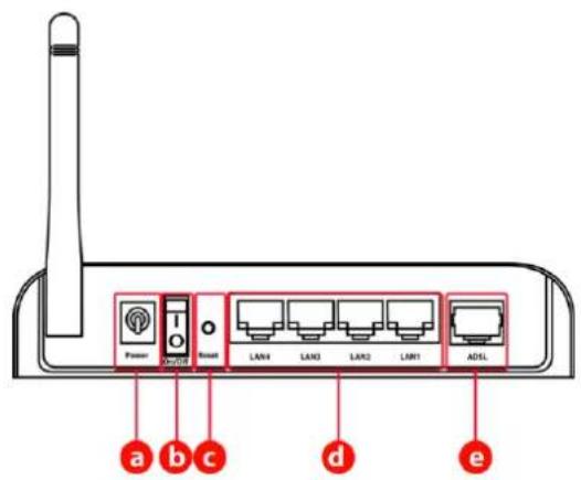
text_image
Power I/O LAN4 LAN3 LAN2 LAN1 ADSL a b c d eTABLE 3. Port Description
| PORT | DESCRIPTION |
| a | Power Inlet |
| b | Power On/Off switch |
| c | Reset Button |
| d | 4 LAN Ports |
| e | ADSL Port |
© (2008) Pirelli Broadband Solutions S.p.A. All Rights Reserved. Proprietary Use Pursuant to Cover Page Instructions.
Hardware Installation
This chapter will guide you through a basic installation of the Router including:
- Positioning the DISCUS™ DRG A124G
- Installing Micro Filters
- Connecting the Router to your network
- Setting up your computer for networking with the Router

Please read carefully the Safety Information in Appendix "A"
ISP SETTINGS
Please collect the following information from your ISP before setting up the Router:
- ISP dial-up phone number
- IP address for your ISP's Gateway Server and Domain Name Server
- An ISP account which includes ISP dial-up username and password
- IP address and subnet mask (for fixed IP users only)
© (2008) Pirelli Broadband Solutions S.p.A. All Rights Reserved. Proprietary Use Pursuant to Cover Page Instructions.
DISCUS™ DRG A124G
POSITIONING THE ROUTER
The router can be positioned at any convenient location in your office or home. No special wiring or cooling requirements are needed. You should, however, comply with the following guidelines:
- Keep the Router away from any heating devices
- Do not place the Router in a dusty or wet environment
You should also remember to turn off the power, remove the power cord from the outlet and keep your hands dry when you install the Router.
INSTALLING MICRO FILTERS
Before beginning installation you must locate devices in your house requiring a DSL filter such as phones, fax machines, answering machines, dial-up modems, Satellite TV dialers or monitored security systems and attach a DSL filter to any one of them sharing the same phone line as your DSL modem.
To install DSL filters please follow these steps:
- Disconnect the phone cable from the telephone wall socket
- Insert the phone cable into the DSL filter port identified with a phone symbol
- Insert the DSL filter cable into the telephone wall socket

You do not need to attach a DSL filter to unused wall sockets.
FIGURE 1 Micro Filter Installation
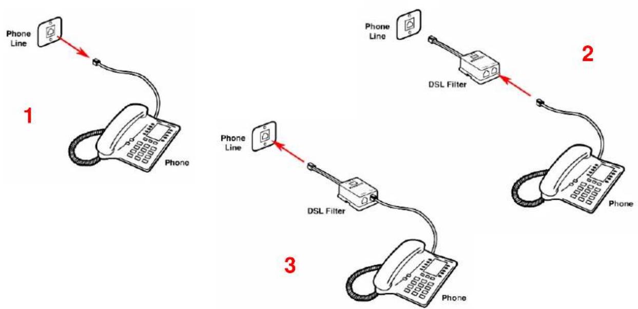
flowchart
graph TD
    A["Phone Line"] --> B["Phone"]
    B --> C["DSL Filter"]
    C --> D["Phone"]
    style A fill:#f9f,stroke:#333
    style B fill:#ccf,stroke:#333
    style C fill:#cfc,stroke:#333
    style D fill:#fcc,stroke:#333
© (2008) Pirelli Broadband Solutions S.p.A. All Rights Reserved. Proprietary Use Pursuant to Cover Page Instructions.
DISCUS™ DRG A124G
POWERING UP THE ROUTER
To power up the Router:
- Plug the power adapter into the power adapter port located on the rear of the Router
- Plug the power adapter into a standard electrical wall socket
- Press the Power button located on the rear panel of the Router
- Wait for the power LED to turn steady green
In case of power input failure, the Router will automatically restart and begin to operate once the input power is restored.
If the Router is properly configured, it will take about 30 seconds to establish a connection with the ADSL service provider after powering up.
During this time the ADSL Sync indicator will flash. After the ADSL connection has been established, the ADSL Sync indicator will stay on.
CONNECTING THE ROUTER
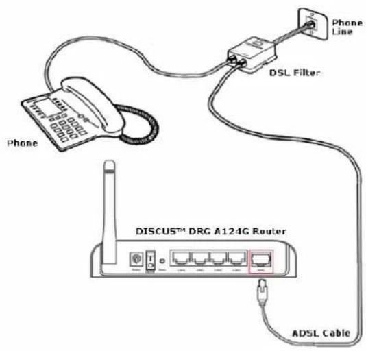
The first step to install the router is to physically connect it to the telephone socket and then to connect it to a computer with Ethernet connection.
To connect the phone cable:
- Connect one end of the phone cable into the DSL filter port identified with a computer symbol
- Connect the other end of the phone cable into the DSL port on the rear of the Router
FIGURE 2 Phone Cable Connection
text_image
Phone DSL Filter Phone Line DISCUSTM DRG A124G Router ADSL Cable© (2008) Pirelli Broadband Solutions S.p.A. All Rights Reserved. Proprietary Use Pursuant to Cover Page Instructions.
DISCUS™ DRG A124G
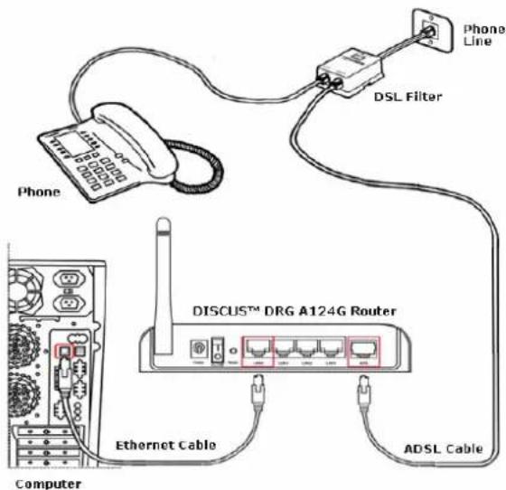
To connect the Ethernet cable:
- Connect one end of the Ethernet cable into one of the four Ethernet ports on the rear of the Router
- Connect the other end of the Ethernet cable into the Ethernet Network card of your computer
- Verify if the Ethernet Network card is configured as DHCP client, otherwise configure it to remain in the same local network of the router interface (see chapter "Setting Up Your Computer")
The LAN port on the Router auto-negotiates the connection speed and the duplex mode with the connecting device.
Use twisted-pair cabling to connect the Router to an Ethernet adapter on your PC. Otherwise, cascade any of the LAN ports on the Router to an Ethernet hub or switch. When inserting an RJ-45 connector, be sure the tab on the connector clicks into position to ensure that is properly seated.

Do not plug a phone jack into RJ-45. This may damage the Router. Instead, use only twisted-pair cables with RJ-45 connectors that conform with FCC standards.

Use 100-ohm shielded or unshielded twisted-pair cable with RJ-45 connectors for all Ethernet ports. We recommend using Category 5 cable for connections with the device. Also, make sure the length of each twisted-pair cable does not exceed 100 meters (328 feet).
FIGURE 3 Ethernet Cable Connection
text_image
Phone DSL Filter Phone Line DISCUSTM DRG A124G Router Ethernet Cable ADSL Cable Computer© (2008) Pirelli Broadband Solutions S.p.A. All Rights Reserved. Proprietary Use Pursuant to Cover Page Instructions.
DISCUS™ DRG A124G
The Router has the ability to dynamically allocate network addresses to the computers on your network using DHCP. However, your computers need to be configured correctly for this to take place. To change the configuration of your computers to allow this, follow the instructions in this chapter.
INSTALL SOFTWARE

The very first time you set up your computer, we recommend you to use the Smart Setup Configuration Utility if your ISP has provided you with.
Before installing the DISCUS™ DRG A124G software please close all applications to avoid any conflict.
This utility offers a guided product tour, a step by step hardware installation guide, a software installation guide, a setup and a driven user registration with DSL Internet connection line check.
Smart Setup Configuration Utility allows, for supported Microsoft® Windows Operating Systems, to setup automatically your computer Ethernet settings.
To launch it, insert the CD-ROM in CD-ROM unit: if the auto-play function is enabled it will start automatically, otherwise open it manually from "x.", where x is your CD-ROM drive letter.
ETHERNET CONNECTION
You have to verify the existence of a TCP/IP protocol stack and, then, according to your Operating System, to establish an Ethernet connection to the Router. This connection will require you to enable your computer to receive from the Router its own IP Address automatically: in such a case, the Router acts like the DHCP server in your local network.
TCP/IP CONFIGURATION
To access the Internet through the Router, you must configure the network settings of the computers on your LAN to use the same IP subnet as Router. The default IP settings for the Router are:
IP ADDRESS: 192.168.1.1
SUBNET MASK: 255.255.255.0
These settings can be changed to fit your network requirements, but you must first configure at least one computer to access the router's web configuration interface in order to make the required changes.
DISCUS™ DRG A124G
ETHERNET CONNECTION >> TCP/IP PROTOCOL INSTALLATION
This procedure requires the TCP/IP protocol installed on your computer. Refer to the following chapters and to your Microsoft® Windows or Apple® MacOS 10.x operating systems manuals.
Microsoft® Windows 98SE, ME, 2000
- Put in the CD-ROM drive your Windows installation CD-ROM
- Starting from Start -> Settings -> Control Panel -> Network Control Panel, make a double click on the Network icon
- Select Configuration -> TCP/IP and then click on the Add button
- Select Protocols, click on Add button and choose Microsoft TCP/IP. Then click on the OK button
- After the computer reboots, you're ready to configure the TCP/IP settings. Configure the Network adapter to obtain automatically an IP address
Microsoft® Windows XP
- Put in the CD-ROM drive your Windows installation CD-ROM
- Starting from Start -> Settings -> Control Panel make a double click on the Network icon.
- Select Protocol and click on the Add button. Select Microsoft and TCP/IP, then click on the OK button.
- Configure the Network adapter to obtain automatically an IP address.
Apple® MacOS 10.x
TCP/IP is installed on a MacOS system as part of Open Transport.
ETHERNET CONNECTION
MS WINDOWS 98SE, ME, 2000
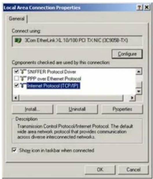
To configure TCP/IP on these Operating Systems follow these steps:
- Select Start -> Settings -> Control Panel and make a double click on the Network icon.
- Select Configuration ->TCP/IP then click on Properties button.
© (2008) Pirelli Broadband Solutions S.p.A. All Rights Reserved. Proprietary Use Pursuant to Cover Page Instructions.
DISCUS™ DRG A124G
FIGURE 4 Local Area Connection Properties
text_image
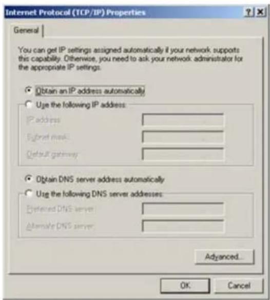
Local Area Connection Properties General Connect using: 3Com EtherLink XL 10/100 PCI TX NIC (3C9058-TX) Configure Components checked are used by this connection: ✓ SNIFFER Protocol Driver ☐ PPP over Ethernet Protocol ✓ Internet Protocol (TCP/IP) Install... Uninstall Properties Description Transmission Control Protocol/Internet Protocol. The default wide area network protocol that provides communication across diverse interconnected networks. ✓ Show icon in taskbar when connected OK Cancel- Select the IP Address Tab, then check to obtain an automatically IP address. Click on OK button.
FIGURE 5 Internet Protocol (TCP/IP) Properties
text_image
Internet Protocol (TCP/IP) Properties General You can get IP settings assigned automatically if your network supports this capability. Otherwise, you need to ask your network administrator for the appropriate IP settings. Obtain an IP address automatically Use the following IP address: P address Subnet mask Default gateway Obtain DNS server address automatically Use the following DNS server addresses: P selected DNS server Alternate DNS server Advanced... OK Cancel© (2008) Pirelli Broadband Solutions S.p.A. All Rights Reserved. Proprietary Use Pursuant to Cover Page Instructions.
DISCUS™ DRG A124G
- A system reboot will be required to make the changes real.
- Enter http://192.168.1.1/ in the address bar of your browser to open the DISCUS™ DRG A124G Home Page.
ETHERNET CONNECTION
MS WINDOWS XP
To configure TCP/IP on MS Windows XP Operating System follow these steps:
- On the Windows desktop, click Start -> Settings -> Control Panel and make a double click on the Network and Dial-Up connections icon.
- Select Protocols ->TCP/IP then click on Properties button.
FIGURE 6 Local Area Connection Properties
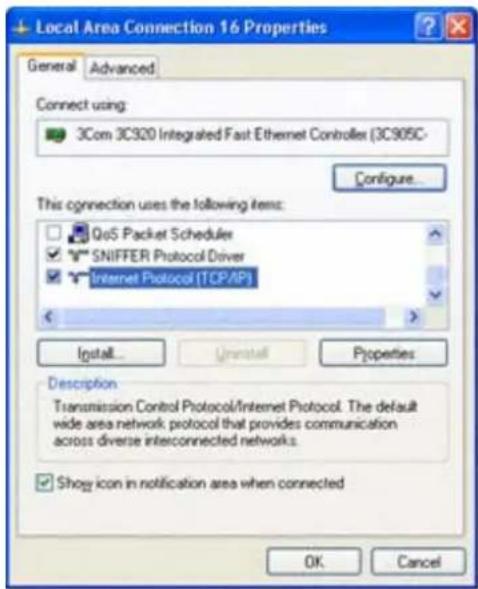
text_image
Local Area Connection 16 Properties General Advanced Connect using: 3Com 3C920 Integrated Fast Ethernet Controller (3C905C- Configure... This connection uses the following items: QoS Packet Schedules SNIFFER Protocol Driver Internet Protocol [TCP/IP] Install... Uninstall Properties Description Transmission Control Protocol/Internet Protocol. The default wide area network protocol that provides communication across diverse interconnected networks. Show icon in notification area when connected OK Cancel- If "Obtain an IP address automatically" and "Obtain DNS server address automatically" are already selected, your computer is already configured for DHCP. If not, select these options.
DISCUS™ DRG A124G
FIGURE 7 Internet Protocol (TCP/IP) Properties
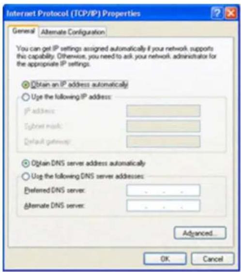
text_image
Internet Protocol (TCP/IP) Properties General Alternate Configuration You can get IP settings assigned automatically if your network supports this capability. Otherwise, you need to ask your network, administrator for the appropriate IP settings. Obtain an IP address automatically Use the following IP address: IP address: Subnet mask: Default gateway: Obtain DNS server address automatically Use the following DNS server addresses: Preferred DNS server: - - - Alternate DNS server: - - - Advanced... OK CancelDISABLE HTTP PROXY
You need to verify that the "HTTP proxy" feature of your web browser is disabled. This is so that your browser can view the Router's HTML configuration pages.
OBTAIN IP SETTINGS FROM ROUTER
MS WINDOWS 98SE, ME, 2000
Now that you've configured your computer to connect to your Router, it needs to obtain new network settings. By releasing old DHCP IP settings and renewing them with settings from your Router, you can verify that you've configured your computer correctly.
-
On the Windows desktop, select the Start > Programs > Accessories > Command Prompt menu item
-
In the Command prompt window, type "ipconfig/release" and press the ENTER key
© (2008) Pirelli Broadband Solutions S.p.A. All Rights Reserved. Proprietary Use Pursuant to Cover Page Instructions.
FIGURE 8 Command Prompt (IPCONFIG command)
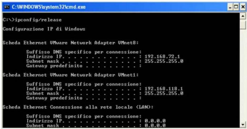
text_image
C:\>ipconfig/release Configurazione IP di Windows Scheda Ethernet VMware Network Adapter UMnet8: Suffisso DNS specifico per connessione: Indirizzo IP. . . . . . . . . . . . . . : 192.168.72.1 Subnet mask . . . . . . . . . . . . . . . : 255.255.255.0 Gateway predefinito . . . . . . . . . . . . Scheda Ethernet VMware Network Adapter UMnet1: Suffisso DNS specifico per connessione: Indirizzo IP. . . . . . . . . . . . . . : 192.168.118.1 Subnet mask . . . . . . . . . . . . . . : 255.255.255.0 Gateway predefinito . . . . . . . . . Scheda Ethernet Connessione alla rete locale- Type "ipconfig/renew" and press the ENTER key. Verify that your IP Address is now 192.168.1.xxx, your Subnet Mask is 255.255.255.0 and your Default Gateway is 192.168.1.1. These values confirm that your ADSL Router is functioning.
FIGURE 9 Command Prompt (IPCONFIG command)
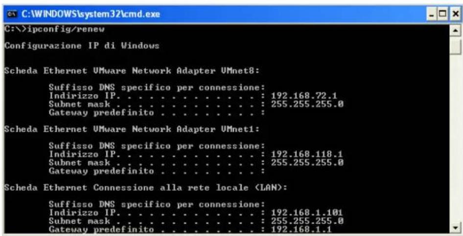
text_image
C:\>ipconfig/renew Configurazione IP di Windows Scheda Ethernet VMware Network Adapter UMnet8: Suffisso DNS specifico per connessione: Indirizzo IP. . . . . . . . . . . . . : 192.168.72.1 Subnet mask . . . . . . . . . . . . . : 255.255.255.0 Gateway predefinito . . . . . . . . . . . : Scheda Ethernet VMware Network Adapter UMnet1: Suffisso DNS specifico per connessione: Indirizzo IP. . . . . . . . . . . . . : 192.168.118.1 Subnet mask . . . . . . . . . . . . . : 255.255.255.0 Gateway predefinito . . . . . . . . . . Scheda Ethernet Connessione alla rete locale (LAN): Suffisso DNS specifico per connessione: Indirizzo IP. . . . . . . . . . . . : 192.168.1.101 Subnet mask . . . . . . . . . . . : 255.255.255.0 Gateway predefinito . . . . . . . . : 192.168.1.1- Close the Command Prompt window
© (2008) Pirelli Broadband Solutions S.p.A. All Rights Reserved. Proprietary Use Pursuant to Cover Page Instructions.
DISCUS™ DRG A124G
OBTAIN IP SETTINGS FROM ROUTER >> MS WINDOWS XP
Now that you've configured your computer to connect to your Router, it needs to obtain new network settings. By releasing old DHCP IP settings and renewing them with settings from your Router, you can verify that you've configured your computer correctly.
- On the Windows desktop, click Start > Programs > Accessories > Command Prompt menu item
- In the Command prompt window, type "ipconfig/release" and press the EN-TER key
- Type "ipconfig/renew" and press the ENTER key. Verify that your IP Address is now 192.168.1.xxx, your Subnet Mask is 255.255.255.0 and your Default Gateway is 192.168.1.1. These values confirm that your ADSL Router is functioning.
- Close the Command Prompt window
ETHERNET CONNECTION >> MAC OS 10.X
To configure TCP/IP on MAC OS 10.x follow these steps:
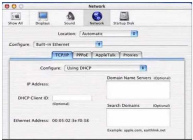
- Open the Apple Menu > System Preferences and select Network.
- From the Show drop down list, according to the type of connection used, select Built-in Ethernet.
- Select the TCP/IP tab.
- Select DHCP from the Configure pop-up menu to have a dynamic IP address.
FIGURE 10 Network panel on MAC OS 10.x
text_image
Network Show All Displays Sound Network Startup Disk Location: Automatic Configure: Built-in Ethernet TCP/IP PPPoE AppleTalk Proxies Configure: Using DHCP IP Address: DHCP Client ID: (Optional) Ethernet Address: 00:05:02:3e:f0:38 Domain Name Servers (Optional) Search Domains (Optional) Example: apple.com, earthlink.net- Click Apply Now button.
- Click on the Register button to save the changes in the Control Panel.
- Enter http://192.168.1.1/ in the address bar of your browser to open the DISCUS™ DRG A124G Login Page.
WI-FI CONNECTION

It requires a computer with 802.11b/g (Wi-Fi Certified) wireless adapter installed.
- Install your wireless adapter according to the manufacturer's instructions and verify that your computer is set to obtain an IP address automatically (DHCP mode).

You will need to properly configure your adapter to communicate with the DISCUS™ DRG A124G according to the configuration rules.
- In the configuration window of your wireless adapter scan the wireless network (marked with the relevant SSID name) present in your physical environment.
- Select the SSID of the DISCUS™ DRG A124G
DISCUS™ DRG A124G
- Complete the configuration of the wireless adapter with the same parameters of the DISCUS™ DRG A124G which are:
• RF channel; automatically detect (default = 6)
- WEP encryption enable or disable (default = Disable)
- WEP key size
- WEP key used
To check the connection, connect to the DISCUS™ DRG A124G Login Page (see Figure 11), entering http://192.168.1.1
FIGURE 11 DISCUS™ DRG A124G Login Page

text_image
INFOSTRADA DISCUS™ DRG A124G Login Screen Username: Password: LOGIN CANCEL Please enter correct password for Administrator Access. Thank you. We suggest that you use Internet Explorer 5.5 or above at a minimum of 1024x768 resolution. Copyright © 2007 Pirelli, Inc. All rights reserved. Firmware version 1_099-W (Mar 26 2008 15:04:32)DISCUS™ DRG A124G
This Page has been intentionally left blank
© (2008) Pirelli Broadband Solutions S.p.A. All Rights Reserved. Proprietary Use Pursuant to Cover Page Instructions.
Router Configuration
Upon TCP/IP configuration on a client computer, it is possible to configure the Router using the web browser. Internet Explorer 5.5 or above, Netscape Navigator, Mozilla, Firefox and Opera are supported.
To access the management interface, enter the default IP address of the Router in your web browser: http://192.168.1.1. The default login ID is "admin" and default password is "admin" (see Figure 1). Click LOGIN button to access the management interface.
FIGURE 1 Access Screen (Login)

text_image
INFOSTRADA Discus™ DRG A124G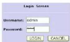
Please enter correct password for Administrator Access. Thank you. We suggest that you use Internet Explorer S.5 or above at a minimum of 1024x768 resolution. Copyright © 2007 Pinelli, Inc. All rights reserved. Firmware version 1_095-W (Mar 26 2008 15:04:32)
© (2008) Pirelli Broadband Solutions S.p.A. All Rights Reserved. Proprietary Use Pursuant to Cover Page Instructions.
DISCUS™ DRG A124G

Password can contain from 3-12 alphanumeric characters and is case sensitive.
MANAGEMENT INTERFACE
The Setup Wizard is located on the top of the left hand side. Use the setup Wizard for a quick and easy configuration of your Internet connection and basic wireless settings.
MAKING CONFIGURATION CHANGES
Configurable parameters have a dialog box or a drop-down menu. Once a configuration change has been made on a screen, click APPLY > SAVE SETTINGS or NEXT buttons on the screen to enable the new settings.
ADVANCED CONFIGURATION PARAMETERS
The left-hand side displays the main menu and the right-hand side shows descriptive Status information (see Figure 2). The main menu item is described in Table 1.
FIGURE 2 Router Home Page
Status
You can use the Status screen to see the connection status for the router's WAN/LAN interfaces, firmware and hardware version numbers, any illegal attempts to access your network, as well as information on all DHCP client PCs currently connected to your network.
Current Time: 08/01/2003 00:05:19 am
INTERNET
ADSL1 DISCONNECTED
GATEWAY
IP Address: 192.168.1.1
Subnet Music 255,255,255.0
DHCF Servar: Enabled
Firewall: Disable
CHP: Enabled
refleen! enabled
INFORMATION
Numbers of DHCP Clients: 1
Runtime Code Version:
1.095-06 (Mar 26 2008 15:04:32)
Boot Code Versions: ¥1,10.0
ADSL Modem Code Version E2541.14 A
LAN MAC Address 00-1C-A2-D9-B2-E0
MAN MA Address: 01-1C-X2-D4-B2-E1
Wires MAC Address: 10-1C-A2-D9-B2-F1
Hardware Version: 01
Serial Hum: 712710000005
LAN Status
| Part No. | Link | Speed | Duplex |
| LAN1 | DOWN | ||
| LAN2 | DOWN | ||
| LAN3 | DOWN | ||
| LAN4 | UP | 190 | FULL |
ATMPVC
| VCL | |
| VPI/VCJ | 8/25 |
| Encapsulation | LLC |
| Protocol | PPPoE |
| IP Address | Down |
| VC2 | |
| VPI/MCI | 8/37 |
| Encapsulation | LLC |
| Protocol | MAC Encapsulated Routing |
| IP Address | 0.0.0.0 |
In the table below, the list of command menu items used for Router Management is shown.
© (2008) Pirelli Broadband Solutions S.p.A. All Rights Reserved. Proprietary Use Pursuant to Cover Page Instructions.
TABLE 1 Command menu items
| PARAMETER | DESCRIPTION |
| SYSTEM | It sets the local time zone, the password for administrator access and the IP address of a PC that will be allowed to manage the Router remotely. Also set up the DNS function here (see chapter 5) |
| WAN | It specifies the Internet connection settings (see chapter 6) |
| LAN | It sets the TCP/IP configuration for the Router LAN interface DHCP clients. Besides, it sets up the UPnP function (see chapter 7) |
| WIRELESS | It configures the radio frequency, SSID and security for Wireless communication (see chapter 8) |
| NAT | It configures Address Mapping, virtual server and special applications (see chapter 9) |
| ROUTING | It sets the routing parameters and it displays the current routing table (see chapter 10) |
| FIREWALL | It configures a variety of security and specialized function including: Access Control, URL blocking, Internet access control scheduling, intruder detection and DMZ (see chapter 11) |
| SNMP | Community string and trap server settings (see chapter 12) |
| UPnP | It allows to enable/disable Universal Plug and Play settings (see chapter 13) |
| QoS | It configures Quality of Service settings (see chapter 14) |
| ADSL | It sets the ADSL operation type and shows the ADSL status (see chapter 15) |
| DDNS | It configures the Dynamic DNS function (see chapter 16) |
| TOOLS | It contains options to ping network connection, trace routes, to backup & to restore the current configuration, to restore all configuration settings to the factory defaults, to update system firmware or to reset the system (see chapter 17) |
| STATUS | It provides WAN connection type and status, firmware and hardware version numbers, system IP settings, as well as DHCP, NAT and firewall information. It displays the number of attached clients, the firmware version, the physical MAC address for each media interface and the hardware version and serial number. It shows the security and DHCP client log (see chapter 18) |
© (2008) Pirelli Broadband Solutions S.p.A. All Rights Reserved. Proprietary Use Pursuant to Cover Page Instructions.
DISCUS™ DRG A124G
This Page has been intentionally left blank
© (2008) Pirelli Broadband Solutions S.p.A. All Rights Reserved. Proprietary Use Pursuant to Cover Page Instructions.
System Section
This section is to be used to properly configure the Router's basic settings, as time zone, password, remote management and DNS (see Figure 1)
FIGURE 1 Command list on SYSTEM section
System Settings
This page includes all the basic configuration tools for the router, such as time zone, password settings, and remote management.
SYSTEM
TIME SETTINGS
Select your local time zone from the drop-down menu (see Figure 2). This information is used for log entries and client filtering.
FIGURE 2 TIME ZONE SETTINGS command menu on SYSTEM section
Time Settings
Set Time Zone:
Use this setting to insure the time-based client filtering feature and system log entries are based on the correct localized time.
(GMT+01:00)Amsterdam, Berlin, Bern, Rome, Stockholm, Vienna
Configure Time Server (NTP):
You can automatically maintain the system time on your ADSL router by synchronizing with a public time server over the Internet.
Enable Automatic Tree Server Maintenance
When you enable this option you will need to configure two different time servers, use the options below to set the primary and secondary HTP servers in your area.
| Primary Server | 129.132.2.21 - Europe |
| Secondary Server | 130.149.17.8 - Europe |
| Tertiary Server | 132.163.4.102 - North America |
HELP SAVE SETTINGS CANCEL
© (2008) Pirelli Broadband Solutions S.p.A. All Rights Reserved. Proprietary Use Pursuant to Cover Page Instructions.
DISCUS™ DRG A124G
If you want to automatically synchronize the ADSL Router with a public time server, check the box to Enable Automatic Server Maintenance. Select the desired servers from the drop-down menus.
SYSTEM >> PASSWORD SETTINGS
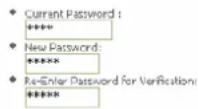
Use this screen to change the password for accessing the management interface.
FIGURE 3 PASSWORD SETTINGS command on SYSTEM section
Password Settings Set a password to restrict management access to the router.
- Idle Time Out: 10 Min (Idle Time = 0 : NO Time Out)
HELP SAVE SETTINGS CANCEL
Password can contain from 3-12 alphanumeric characters and are case sensitive.

If you lost the password, or you cannot gain access to the user interface, press the reset button or the rear panel, holding it down for at least five seconds to restore the factory defaults. The default password is "admin".
Enter a maximum Idle Time Out (in minutes) to define a maximum period of time for which the login session is maintained during inactivity. If the connection is inactive for longer than the maximum idle time, it will perform system logout and you have to log in again to access the management interface (Default:10 minutes).
SYSTEM >> DNS
Domain Name Servers (DNS) are used to map a domain name (e.g., www.somecompany.com) with the IP address (e.g., 64.147.25.20). Your ISP should provide the IP address of one or more Domain Name Servers. Enter those addresses on this screen, and click SAVE SETTINGS button (see Figure 5)
DISCUS™ DRG A124G
FIGURE 5 DNS setting command on SYSTEM section
DNS
A Domain Name Server (DNS) is an index of IP addresses and Web addresses. If you type a Web address into your browser, such as, a DNS server will find that name in its index and find the matching IP address: www.xnaw.com. Most ISPs provide a DNS server for speed and convenience. Since your Service Provider may connect to the Internet with dynamic IP settings, it is likely that the DNS server IPs are also provided dynamically. However, if there is a DNS server that you would rather use, you need to specify the IP address here.
| Domain Name Server (DNS) Address | 192 | 168 | 1 | 40 |
| Secondary DNS Address (optional) | 192 | 168 | 10 | 4 |
HELP SAVE SETTINGS CANCEL
DISCUS™ DRG A124G
This Page has been intentionally left blank
© (2008) Pirelli Broadband Solutions S.p.A. All Rights Reserved. Proprietary Use Pursuant to Cover Page Instructions.
WAN Section
This section allows to specify the WAN connection parameters and the ATM PVC settings provided by your Internet Services Provider (ISP).
The Figure 1 shows different kind of connections used by the Router to connect to the network.
FIGURE 1 WAN Main screen
WAN Settings
The router can be connected to your service provider in any of the following ways:
ATM PVC Clone MAC
To configure ATM VC parameters To configure WAN Interface MAC Address
The Router supports the following two modes:
- ATM PVC
- Clone MAC
WAN >> ATM PVC
By selecting the first mode (ATM PVC), it is necessary to enter the virtual connection parameters (see Figure 2).
© (2008) Pirelli Broadband Solutions S.p.A. All Rights Reserved. Proprietary Use Pursuant to Cover Page Instructions.
FIGURE 2 List of configured ATM virtual connections
ATM PVC
ADSL router uses ATM as its layer 2 protocol. ATM PVC is a virtual connection which acts as a WAN interface. The Gateway supports up to 8 ATM PVCs.
| Description | VPI/ VCI | Encapsulation | Protocol |
| VC1 | 8/35 | LLC | PPPoE |
| VC2 | 8/37 | LLC | MAC Encapsulated Routing |
| VC3 | 8/32 | LLC | PPPoA |
| VC4 | 8/33 | LLC | 1483 Routing |
| VC5 | 8/34 | LLC | 1483 Bridging |
| VC6 | -/- | --- | --- |
| VC7 | -/- | --- | --- |
| VC8 | -/- | --- | --- |
HELP
TABLE 1 ATM virtual connection parameters
| PARAMETER | DESCRIPTION |
| VC1-VC8 | Click on the desired VC to set the values for the connection. In most cases a single VC will be provided. For single VC use VC1 |
| VPI/VCI | It displays Virtual Path Identifier (VPI) and Virtual Circuit Identifier (VCI) configured for corresponding VC |
| Encapsulation | It displays Encapsulation configured for corresponding VCVC-MUX: Point-to-Point Protocol over ATM Virtual Circuit Multiplexer (null encapsulation) allows only one protocol running per virtual circuit with less overhead.LLC: Point-to-Point Protocol over ATM Logical Link Control (LLC) allows multiple protocols running over one virtual circuit (using slightly more overhead) |
| Protocol | It displays protocols configured for corresponding VC. Configured protocols can be: 1483 Bridging, PPPoA, 1483 Routing, PPPoE, MAC Encapsulated Routing. |
WAN >> ATM INTERFACE 1483 BRIDGING
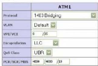
When 1483 Bridging is selected on ATM Interface, a list of parameters is to be filled (see Figure 3). Refer to Table 2 to get information on parameter meaning and values. When all fields have been properly filled, do select the SAVE SETTINGS button.
© (2008) Pirelli Broadband Solutions S.p.A. All Rights Reserved. Proprietary Use Pursuant to Cover Page Instructions.
DISCUS™ DRG A124G
FIGURE 3 ATM interface settings (1483 Bridging) on WAN section
AIM Interface
text_image
ATM1 Protocol 1403 Bridging VLAN Default VPI/VCI 0 /25 Encapsulation LLC QoS Class UBR PCR/SCR/MBS 4000 4000 /10HELP SAVE SETTINGS CANCEL
TABLE 2 List of parameters on 1483 Bridging ATM Interface
| PARAMETER | DESCRIPTION |
| Protocol | 1483 Bridging |
| VLAN | Select the VLAN to use |
| VPI/VCI | Enter the Virtual Path Identifier (VPI) and Virtual Circuit Identifier (VCI) supplied by your ISP |
| Encapsulation | Select the encapsulation used by your ISP from the drop-down menu |
| QoS Class | ATM QoS classes including CBR, UBR and VBR |
| PCR/SCR/MBS | QoS Parameters – PCR (Peak Cell Rate), SCR (Sustainable Cell Rate) and MBS (Maximum Burst Size) are configurable. |
WAN >> ATM INTERFACE PPPoA
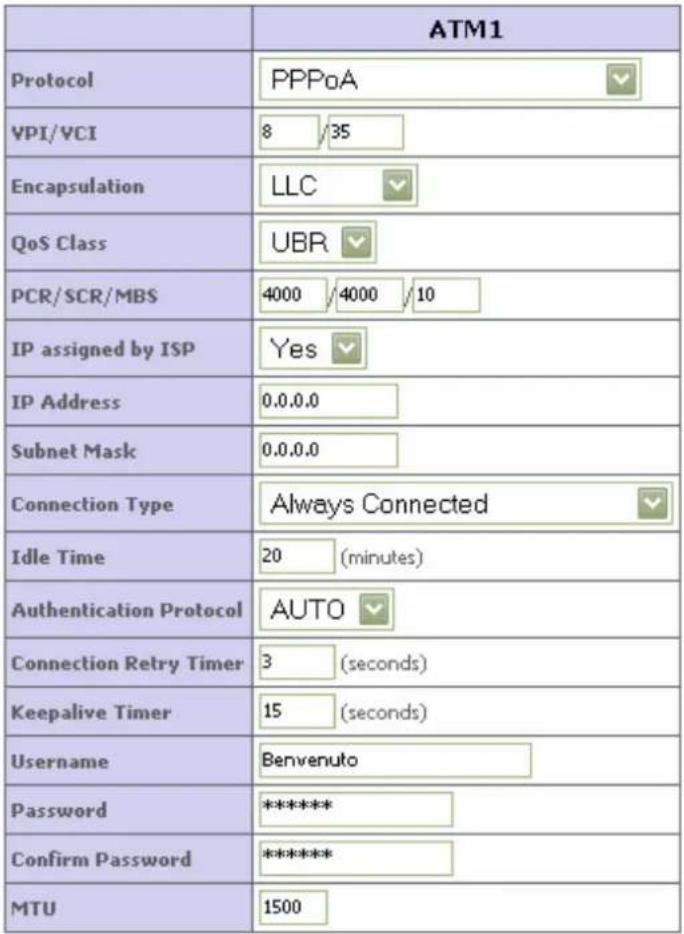
When PPPoA is selected on ATM Interface, a list of parameters is to be filled (see Figure 4). Refer to Table 3 to get information on parameter meaning and values. When all fields have been properly filled, do select the SAVE SETTINGS button.
© (2008) Pirelli Broadband Solutions S.p.A. All Rights Reserved. Proprietary Use Pursuant to Cover Page Instructions.
FIGURE 4 ATM interface settings (PPPoA) on WAN section
ATM Interface
text_image
ATM1 Protocol PPPoA VPI/VCI 8 /35 Encapsulation LLC QoS Class UBR PCR/SCR/MBS 4000 /4000 /10 IP assigned by ISP Yes IP Address 0.0.0.0 Subnet Mask 0.0.0.0 Connection Type Always Connected Idle Time 20 (minutes) Authentication Protocol AUTO Connection Retry Timer 3 (seconds) Keepalive Timer 15 (seconds) Username Benvenuto Password ***** Confirm Password ***** MTU 1500TABLE 3 List of parameters on PPPoA ATM Interface
| PARAMETER | DESCRIPTION |
| Protocol | PPPoA |
| VPI/VCI | Enter the Virtual Path Identifier (VPI) and Virtual Circuit Identifier (VCI) supplied by your ISP |
| Encapsulation | Select the encapsulation used by your ISP from the drop-down menu |
| QoS Class | ATM QoS classes including CBR, UBR and VBR |
| PCR/SCR/MBS | QoS Parameters – PCR (Peak Cell Rate), SCR (Sustainable Cell Rate) and MBS (Maximum Burst Size) are configurable. |
© (2008) Pirelli Broadband Solutions S.p.A. All Rights Reserved. Proprietary Use Pursuant to Cover Page Instructions.
TABLE 3 List of parameters on PPPoA ATM Interface
| PARAMETER | DESCRIPTION |
| IP assigned by ISP | Select Yes if you have a dynamic IP address. Select No if you have a static IP address |
| IP address | Enter the IP address provided by your ISP. For dynamic IP leave this field blank |
| Connection type | It sets the connection mode to Always connected, Auto triggering by traffic or Manual connection. For flat rate services use Always connected |
| Idle time | Enter the maximum idle time for the Internet connection. After this time has been exceeded the connection will be terminated. This setting only applies when Connect type id set to Auto-triggering by traffic |
| Authentication protocol | Select the protocol from the drop down menu |
| Connection retry timer | This is the timer controls the period between two PPP connection establishing retries. Connection retry timer only work when PPP link is in disconnected status |
| Keep alive timer | PPP has its own protocol (LCP echo) to check the PPP connection status periodically, keep alive timer controls the period between two checks. Keep alive timer control work when PPP link is in connected status |
| Username | Enter user name |
| Password | Enter password |
| Confirm Password | Confirm password |
| MTU | Leave the Maximum Transmission Unit (MTU) at the default value unless instructed by your ISP |
WAN >> ATM INTERFACE 1483 ROUTING
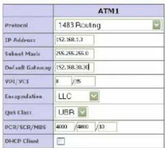
When 1483 Routing is selected on ATM Interface, a list of parameters is to be filled (see Figure 5). Refer to Table 4 to get information on parameter meaning and values. When all fields have been properly filled, do select the SAVE SETTINGS button.
FIGURE 5 ATM interface settings (1483 Routing) on WAN section
ATM Interface
text_image
ATM1 Protocol 1483 Routing IP Address 192.368.5.3 Submit Music 255.268.255.0 Default Gateway 192.368.30.30 VSI/VSI 8 /25 Encapsulation LLC Qas Class UBR PCR/SCR/MBS 4000 /4000 /10 DHCP ClientHELP SAVE SETTINGS CANCEL
TABLE 4 List of parameters on 1483 Routing ATM Interface
| PARAMETER | DESCRIPTION |
| Protocol | 1483 Routing |
| IP address | Enter the IP address provided by your ISP |
| Subnet Mask | Enter the subnet mask address provided by your ISP |
| Default Gateway | Enter the gateway address provided by your ISP |
| VPI/VCI | Enter the Virtual Path Identifier (VPI) and Virtual Circuit Identifier (VCI) supplied by your ISP |
| Encapsulation | Select the encapsulation used by your ISP from the drop-down menu |
| QoS Class | ATM QoS classes including CBR, UBR and VBR |
| PCR/SCR/MBS | QoS Parameters – PCR (Peak Cell Rate), SCR (Sustainable Cell Rate) and MBS (Maximum Burst Size) are configurable. |
WAN >> ATM INTERFACE PPPoE
When PPPoE is selected on ATM Interface, a list of parameters is to be filled (see Figure 6). Refer to Table 5 to get information on parameter meaning and values. When all fields have been properly filled, do select the SAVE SETTINGS button.
© (2008) Pirelli Broadband Solutions S.p.A. All Rights Reserved. Proprietary Use Pursuant to Cover Page Instructions.
DISCUS™ DRG A124G
FIGURE 6 ATM interface settings (PPPoE) on WAN section
ATM Interface
| ATM1 | |
| Protocol | PPPoE |
| VPI/VCI | 8/35 |
| Encapsulation | LLC |
| QoS Class | UBR |
| PCR/SCR/MBS | 4000/4000/10 |
| IP assigned by ISP | Yes |
| IP Address | 192.168.1.3 |
| Subnet Mask | 255.255.255.0 |
| Connection Type | Always Connected |
| Idle Time | 20(minutes) |
| Authentication Protocol | AUTO |
| Connection Retry Timer | 3(seconds) |
| Keepalive Timer | 15(seconds) |
| Username | Bnvenuto |
| Password | ********** |
| Confirm Password | ********** |
| MTU | 1492 |
TABLE 5 List of parameters on PPPoE ATM Interface
| PARAMETER | DESCRIPTION |
| Protocol | PPPoE |
| VPI/VCI | Enter the Virtual Path Identifier (VPI) and Virtual Circuit Identifier (VCI) supplied by your ISP |
| Encapsulation | Select the encapsulation used by your ISP from the drop-down menu |
| QoS Class | ATM QoS classes including CBR, UBR and VBR |
| PCR/SCR/MBS | QoS Parameters – PCR (Peak Cell Rate), SCR (Sustainable Cell Rate) and MBS (Maximum Burst Size) |
© (2008) Pirelli Broadband Solutions S.p.A. All Rights Reserved. Proprietary Use Pursuant to Cover Page Instructions.
TABLE 5 List of parameters on PPPoE ATM Interface
| PARAMETER | DESCRIPTION |
| are configurable. | |
| IP assigned by ISP | Select Yes if you have a dynamic IP address. Select No if you have a static IP address |
| IP address | Enter the IP address provided by your ISP. For dynamic IP leave this field blank |
| Connection type | It sets the connection mode to Always connected, Auto triggering by traffic or Manual connection. For flat rate services use Always connected |
| Idle time | Enter the maximum idle time for the Internet connection. After this time has been exceeded the connection will be terminated. This setting only applies when Connect type id set to Auto-triggering by traffic |
| Authentication protocol | Select the protocol from the drop down menu |
| Connection retry timer | This is the timer controls the period between two PPP connection establishing retries. Connection retry timer only work when PPP link is in disconnected status |
| Keep alive timer | PPP has its own protocol (LCP echo) to check the PPP connection status periodically, keep alive timer controls the period between two checks. Keep alive timer control work when PPP link is in connected status |
| Username | Enter user name |
| Password | Enter password |
| Confirm Password | Confirm password |
| MTU | Leave the Maximum Transmission Unit (MTU) at the default value unless instructed by your ISP |
WAN >> ATM INTERFACE MAC ENCAPSULATED ROUTING
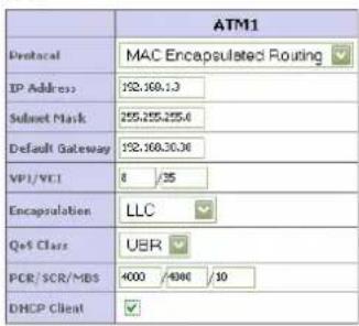
When MAC Encapsulated Routing is selected on ATM Interface, a list of parameters is to be filled (see Figure 7). Refer to Table 6 to get information on parameter meaning and values. When all fields have been properly filled, do select the SAVE SETTINGS button.
© (2008) Pirelli Broadband Solutions S.p.A. All Rights Reserved. Proprietary Use Pursuant to Cover Page Instructions.
DISCUS™ DRG A124G
FIGURE 7 ATM interface settings (MAC Encapsulated Routing) on WAN section
ATM Interface
text_image
ATM1 Protocol MAC Encapsulated Routing IP Address 192.160.13 Subset Mask 255.255.255.6 Default Gateway 192.160.30.36 VPI/VCI 8 /35 Encapsulation LLC QoS Class UER PCR/SCR/MBS 4000 /4000 /10 DHCP ClientHELP SAVE SETTINGS CANCEL
TABLE 6 List of parameters on MAC Encapsulated Routing ATM Interface
| PARAMETER | DESCRIPTION |
| Protocol | MAC Encapsulated Routing |
| IP address | Enter the IP address provided by your ISP |
| Subnet Mask | Enter the subnet mask address provided by your ISP |
| Default Gateway | Enter the gateway address provided by your ISP |
| VPI/VCI | Enter the Virtual Path Identifier (VPI) and Virtual Circuit Identifier (VCI) supplied by your ISP |
| Encapsulation | Select the encapsulation used by your ISP from the drop-down menu |
| QoS Class | ATM QoS classes including CBR, UBR and VBR |
| PCR/SCR/MBS | QoS Parameters – PCR (Peak Cell Rate), SCR (Sustainable Cell Rate) and MBS (Maximum Burst Size) are configurable. |
| DHCP Client | Check the box if your ISP assigns an IP address dynamically. |
WAN >> CLONE MAC ADDRESS
Some ISPs require you to register your MAC address with them, If this is the case, and you have previously registered the MAC address of another device, the MAC address of the Router must be changed to the MAC address that you have registered with your ISP (see Figure 8).
Upon MAC Address insertion, do select the SAVE SETTINGS button.
© (2008) Pirelli Broadband Solutions S.p.A. All Rights Reserved. Proprietary Use Pursuant to Cover Page Instructions.
FIGURE 8 Clone MAC Address panel on WAN section
Clone MAC Address
Some ISPs require you to register your MAC address with them. If you have done this, the MAC address of the Gateway must be changed to the MAC address that you supplied to your ISP.
■ WAN Interface MAC Address
Use the Gateway's default MAC address 00:1C:A2:D9:B2:E1
Use this PC's MAC address 00xC09F48s48s45
LAN menu is to configure the LAN IP address, VLAN binding, Ethernet port speed, to enable the DHCP server for dynamic client address allocation and to set the IP address pool within a domain. In Figure 1 a first section of the main screen on LAN section is shown with available parameters.
FIGURE 1 LAN Main panel
LAN Settings
You can enable DHCP to dynamically allocate IP addresses to your client PCs, or configure filtering functions based on specific clients or protocols. The router must have an IP address for the local network.
VLAN Binding is to define the port-based VLAN belonging of the physical ports. Each physical port can be assigned to any configured VLAN profile.
LAN IP
| IP Address | 192 | 168 | 1 | 1 |
| IP Subset Mask | 255,255 255. | 0 | ||
| DHCP Survey | Enabled | Disabled | ||
YLAN Binding
| Port No. | VLAN | |
| LAN1 | Default | |
| LAN2 | Default | |
| LAN3 | Default | |
| LAN4 | Default | |
Port Configuration
| Port No. | Control |
| LAN1 | Auto |
| LAN2 | Auto |
| LAN3 | Auto |
| LAN4 | Auto |
© (2008) Pirelli Broadband Solutions S.p.A. All Rights Reserved. Proprietary Use Pursuant to Cover Page Instructions.
DISCUS™ DRG A124G
From shown panel it is possible to configure several parameters, as described in Table 1
TABLE 1 List of parameters in LAN section
| PARAMETER | DESCRIPTION |
| LAN IP | |
| IP Address | The IP address of the Router |
| IP Subnet mask | The subnet mask of the network |
| DHCP server | To enable or disable the DHCP server function. By default the DHCP server is enabled for automatic IP address assignment to client devices |
| VLAN binding | |
| LAN1 to LAN4 | Select to set the LAN port to a specific VLAN |
| Port Configuration | |
| LAN1 to LAN4 | Set the port to Auto, 100 Full/Half or 10 Full/Half control |
| DHCP Server Parameters | |
| DHCP Server ID | Enter the ID here |
| Lease Time | Select the time period between two IP addresses assignment |
| IP Address Pool | |
| Start IP / End IP | Specify the start / end IP address of the DHCP pool. Do not include the IP address of the Router in the client address pool. If you change the pool range, make sure the first three octets match the gateway's IP address, i.e., 192.168.1.xxx |
| Domain Name | If your network uses a domain name, enter it here. Otherwise, leave this field blank |
LAN >> VLAN
The Router's VLAN function can be used to create up to 4 VLAN profiles. Once a VLAN profile is created, interfaces can be assigned to the VLAN profile. This is done by setting the VLAN binding (see Figure 2).
FIGURE 2 VLAN settings
VLAN
VLANs are organized and controlled by VLAN Profiles. Up to 4 VLAN profiles can be created. Once a VLAN profile is created, it is empty and user should add interfaces into the VLAN by changing the VLAN setting of that interface. Please note that only those interfaces of IEEE 602 bridging type (ex. LAN ports and 1463 Bridging PVCs) can be added to a VLAN.
• VLAN Table (up to 4 rules)
| No. | VLAN | Grouped Interface | Configure |
| 1 | Default | LAN:LLANG,LAN:D,LAN:H,WLAN:H,ATMS | Edit |
Add VLAN
HELP CANCEL
© (2008) Pirelli Broadband Solutions S.p.A. All Rights Reserved. Proprietary Use Pursuant to Cover Page Instructions.
DISCUS™ DRG A124G

Only interfaces of IEEE 802 bridging type (LAN ports 1-4 and 1483 Bridging PVC's) can be assigned to a VLAN.
Click Add VLAN button on the VLAN panel to add a new VLAN profile. To modify existing VLANs, click the Edit button on Configure field related to VLAN list.
FIGURE 3 VLAN profile configuration
VLAN Profile
Enter parameters of the profile to define a VLAN.
| Description | Default | |||
| IP Address | 192 | 169 | 1 | 1 |
| Subnet Mask | 255 | 255 | 255 | 0 |
| NAT Domain | PrivatePublic | |||
| ISMP Snooping | EnabledDisabled | |||
| ISMP Querier | EnabledDisabled | |||
HELP SAVE SETTINGS CANCEL
TABLE 2 List of parameters on VLAN settings
| PARAMETER | DESCRIPTION |
| Description | Enter a description for the VLAN group, for example: Admin's PC |
| IP address | Enter IP address for the VLAN |
| Subnet Mask | Enter Subnet Mask address for the VLAN |
| NAT Domain | To set the NAT Domain to private or public |
| IGMP Snooping | By enabling it, the feature that allows an Ethernet switch to “listen in” on the IGMP conversation between hosts and routers will be turned on |
| IGMP Querier | By enabling this function, it will send out periodic IGMP queries |
© (2008) Pirelli Broadband Solutions S.p.A. All Rights Reserved. Proprietary Use Pursuant to Cover Page Instructions.
DISCUS™ DRG A124G
This Page has been intentionally left blank
© (2008) Pirelli Broadband Solutions S.p.A. All Rights Reserved. Proprietary Use Pursuant to Cover Page Instructions.
Wireless Section
The Router also operates as a wireless Access Point (AP), allowing wireless computers to communicate with each other. To configure this function, all you need to do is to enable the wireless function, define the radio channel, the SSID and the security options.
Select the Enable radio button, then select the country from the drop down menu, and click on SAVE SETTINGS button. In Figure 1 the WIRELESS main screen is shown: in left-hand side list of command inside this section does appear.
FIGURE 1 WIRELESS MAIN PANEL

text_image
Wireless Settings The router can be quickly configured as an wireless access point for roaming clients by setting the service set identifier (SSID) and channel number. It also supports data encryption and client filtering. Enable or disable Wireless module function : Enable Disable Country Selection ItalySAVE SETTINGS
WIRELESS >> CHANNEL AND SSID
It is necessary to specify a common radio channel and ESSID to be used by the Router and by all of its wireless clients (see Figure 2). Be sure to configure all connected clients with the same values.
© (2008) Pirelli Broadband Solutions S.p.A. All Rights Reserved. Proprietary Use Pursuant to Cover Page Instructions.
FIGURE 2 CHANNEL AND SSID CONFIGURATION
Channel and SSID
This page allows you to define SSID and Channel ID for wireless connections. In the wireless environment, the router can also act as an wireless access point. These parameters are used for the mobile stations to connect to this access point.
| ESSID | Infotrada WiR |
| ESSID Broadcast | ENABLE DISABLE |
| Wireless Mode | Mixed (11b+11g) |
| Channel | 11 |
HELP SAVE SETTINGS CANCEL
WIRELESS >> ACCESS CONTROL
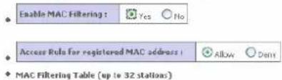
By using the Access Control functionality, it is possible to restrict access on MAC address base. Each PC has a unique identifier known as a Medium Access Control (MAC) address. With MAC filtering enabled, the computers whose MAC address are listed in the filtering table, will be able to connect (or will be denied access) to the Router. In Figure 3 WLAN Access Filtering Table is shown.
FIGURE 3 WLAN MAC FILTERING TABLE
WLAN MAC Filtering Table
For a more secure Wireless network you can specify that only certain Wireless PCs can connect to the Access Point. Up to 32 MAC addresses can be added to the MAC Filtering Table. When enabled, all registered MAC addresses are controlled by the Access Rule.
text_image
Enable MAC Filtering : Yes No Access Rule for registered MAC address : Allow Den MAC Filtering Table (up to 32 stations)© (2008) Pirelli Broadband Solutions S.p.A. All Rights Reserved. Proprietary Use Pursuant to Cover Page Instructions.
TABLE 1. List of fields on WLAN MAC Filtering Table
| PARAMETER | DESCRIPTION |
| Enable MAC filtering | Select to turn on this feature |
| Access Rule for registered MAC address | Select to Allow / Deny access for the registered MAC addresses. Selecting Allow means only MAC addresses registered button here will be able to connect to the Router. Selecting Deny means only the MAC addresses registered here will be denied access to the router. |
| MAC Filtering Table (up to 32 stations) | You can enter up to 32 addresses here in the table. Click Add currently MAC stations button to quickly copy the entry to the MAC Filtering table. |
WIRELESS >> SECURITY
To make the wireless networks safer, the security function should be turned on. In Figure 4 the panel where it is possible to set security is shown. The Router supports WEP (Wired Equivalent Privacy) and WPA (Wi-Fi Protected) security mechanisms.
FIGURE 4 WIRELESS SECURITY SETTINGS
Security
The router can transmit your data securely over the wireless network. Matching security mechanisms must be setup on your router and wireless client devices. You can choose the allowed security mechanisms in this page and configure them in the sub-pages.


The following options are available:
- No WEP, No WPA
- WEP only
- WPA only

By selecting the "No WEP, no WPA" option, any client with the correct SSID will be allowed to connect to this Router. We suggest to turn on the security function to protect wireless communication.
WIRELESS >> SECURITY
WEP
Figure 5 shows the WEP configuration panel. To use WEP to protect the wireless network, it is necessary to set the same parameters for the Router and for all the wireless clients.
© (2008) Pirelli Broadband Solutions S.p.A. All Rights Reserved. Proprietary Use Pursuant to Cover Page Instructions.
DISCUS™ DRG A124G
FIGURE 5 WEP CONFIGURATION PANEL
WEP
WED is the basic mechanism to transmit your data securely over the wireless network. Matching encryption keys must be setup on your router and wireless client devices to use WED.
| WED Mode | 64-bit | 126-bit |
| Key Entry Method | Hex | ASCII |
| Key Provisioning | Static | Dynamic |
Static WEP Key Setting
10/26 hex digits for 64-WEP/120-WEP
| Default Key ID | 1 | |
| Passphrase | ☑ Test | (1=92 characters) |
| Key 1 | 01010101 | |
| Key 2 | 02020202 | |
| Key 3 | 03030303 | |
| Key 4 | 04040404 | |
| Clear | ||
HELP SAVE SETTINGS CANCEL
TABLE 2. List of parameters on WEP configuration
| PARAMETER | DESCRIPTION |
| WEP Mode | Select 64 bit or 128 bit key to use for encryption |
| Key Entry Method | Select Hex or ASCII. ASCII is selected, the Passphrase checkbox will not available |
| Key Provisioning | Select Static or Dynamic. If you choose Dynamic, then you should also set up the 802.1X function |
| Static WEP Key Settings | |
| Default Key ID | From 1-4 characters |
| Passphrase | Two ways to generate the encryption keys, with our without the passphrase function.To generate encryption keys using the passphrase function, check the Passphrase box, and enter the string. Note that the passphrase can consist of up to 32 alphanumeric characters.To generate encryption keys without using the passphrase function, make your selections in WEP Mode and Key Entry Method, then encryption keys would be generated automatically. It is also possible to manually enter the encryption keys. Do enter five hexadecimal pairs of digits for the 64-bit WEP mode, or enter 13 pairs for the 128-bit WEP Mode. Note that a hexadecimal digit is a number or letter in the range 0-9 of A-F |

Before saving settings the key is shown in clear text. If your wireless client does not have a passphrase utility make a note of the default key before saving settings. This is so you can configure your wireless client with the proper SSID to connect to this Router.
We suggest you to turn on the security function to protect your wireless communication.
© (2008) Pirelli Broadband Solutions S.p.A. All Rights Reserved. Proprietary Use Pursuant to Cover Page Instructions.
DISCUS™ DRG A124G
WIRELESS >> SECURITY
WPA
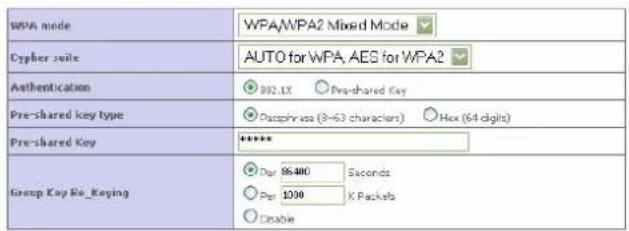
Figure 6 shows the WPA settings. The Wi-Fi Protected Access (WPA) combines temporal key integrity protocol (TKIP) and 802.1X mechanisms. It provides dynamic key encryption and 802.1X authentication service. The Router supports both WPA and WPA2.
FIGURE 6 WPA SETTINGS PANEL
WPA
WPA is a security enhancement that strongly increases the level of data protection and access control for existing wireless LAN. Matching authentication and encryption methods must be setup on your router and wireless client devices to use WPA.
text_image
WPA mode WPA/WPA2 Mixed Mode Cypher scale AUTO for WPA, AES for WPA2 Authentication 902.1X Pre-shared Key Pre-shared key type Dissphrase (8~63 characters) Hex (64 digits) Pre-shared Key ***** Group Key Key_Keying Par 85480 Seconds Par 1000 K Packets EnableHELP SAVE SETTINGS CANCEL
TABLE 3. List of parameters on WPA settings menu
| PARAMETER | DESCRIPTION |
| WPA Mode | Select WPA, WPA2 or mixed |
| Cipher suite | Select TKIP + AES, or AES |
| Authentication | Choose 802.1X or Pre-shared Key802.1X: for the network environment with a RADIUS server.Pre-shared Key: for the SOHO network environment without an authentication server |
| Pre-shared Key type | Select Passphrase or Hex |
| Pre-shared Key | Enter the key in this field |
| Group Key Re_Keying | The period of renewing broadcast / multicast key |
WIRELESS >> SECURITY
802.1X
Figure 7 shows the 802.1X settings. If 802.1X is used in the network, then this Router functionality can be enabled.
© (2008) Pirelli Broadband Solutions S.p.A. All Rights Reserved. Proprietary Use Pursuant to Cover Page Instructions.
FIGURE 7 802.1X SETTINGS PANEL
802.1X
This page allows you to set the 802.0x, a method for performing authentication to wireless connection. These parameters are used for this access point to connect to the Authentication Server.
| 902.1X Authentication | Enable | Disable |
| Session Idle Timeout | 200 | Seconds ( 0 for no timeout checking ) |
| Re Authentication Period | 3600 | Seconds ( 0 for no re-authentication ) |
| Quiet Period | 60 | Seconds after authentication failed |
| Server Type | RADIUS | |
| RADIUS Server Parameters | |
| Server IP | 192 159 1 1 |
| Server Port | 1912 |
| Secret Key | **** |
| NAS ID | Infostrada |
HELP SAVE SETTINGS CANCEL
TABLE 4. List of parameters on 802.1X settings menu
| PARAMETER | DESCRIPTION |
| 802.1X Authentication | Select to enable or disable this function |
| Session Idle Timeout | It defines a maximum period of time for which the connection is maintained during inactivity |
| Re-Authentication Period | It defines a maximum period of time for which the authentication server will dynamically re-assign a session key to a connected client |
| Quiet Period | It defines a maximum period of time for which the Router will wait between failed authentication |
| Server Type | This is set to RADIUS |
| Server IP | The IP address of our authentication server |
| Server Port | The port used for authentication service |
| Secret Key | The secret key shared between the authentication server and its clients |
| NAS-ID | Defines the request identifier of the Network Access Server |
WIRELESS >> WI-FI PROTECTED SETUP
The Wi-Fi Protected Setup (WPS) is the industry standard method to simplify the security setup and management of the Wi-Fi networks. It is possible to setup
© (2008) Pirelli Broadband Solutions S.p.A. All Rights Reserved. Proprietary Use Pursuant to Cover Page Instructions.
DISCUS™ DRG A124G
FIGURE 8 WI-FI PROTECTED SETUP PANEL
Wi-Fi Protected Setup (WPS)
Wi-Fi Protected Setup (WPS)

Wi-Fi Protected Setup(WPS) is the industry standard method to simplify the security setup and management of the Wi-Fi networks. You now can easily setup and connect to a WPA enabled 602.11 network with WPS-certificated devices using other Personal Information Number(PIN) or Flush Button Configuration(PDC) method. Legacy devices without WPS can be added to the network using the traditional manual configuration method.
Apply Changes
1) Personal Information Number(DIN) Method
If an external register is available, you can also enter Router's PIN at the external registrar. To change Router's PIN, click "Generate New PIN" or click "Restore Default PIN" to reset the PIN to factory default.
Erter Client Devices PIN

If an external registrar is available, you can also enter Router's PIN at the external registrar. To change Router's PIN, click "Generate New PIN" or click "Restore Default PIN" to reset the PIN to factory default.
Router PIN:12345670
Generate New FIN

2) Push Button Configuration(PBC) Method
Push and hold PBC button on your router for 3 seconds or click "Start PBC". Then start PBC on the device you want to connect to the router within 2 minutes.
SextFRC
WIRELESS >> WDS
The Wireless Distribution System (WDS) provides a mean to extend the range of a Wireless Local Area Network (WLAN). WDS allows an Access Point (AP) to establish a direct link to other APs and to allow stations to roam freely within the area covered by the WDS (see Figure 9).
FIGURE 9 WDS SETTINGS ON WIRELESS SECURITY SECTION
WDS
The Wireless Distribution System (WDS) provides a means to extend the range of a Wireless Local Area Network (WLAN). WDS allows an Access Point (AP) to establish a direct link to other APs and to allow stations to roam freely within the area covered by the WCS.


AP MAC Address Table (up to 4 APs)


© (2008) Pirelli Broadband Solutions S.p.A. All Rights Reserved. Proprietary Use Pursuant to Cover Page Instructions.
TABLE 5. List of setting fields on WDS settings menu
| PARAMETER | DESCRIPTION |
| Enable or disable WDS fea-tures | Select to turn on / turn off this function |
| Rescan | Click this to refresh the list of available access point |
Available access points will then show up on the AP MAC Address Table; check the related box to add that particular access point to the WDS.
WIRELESS >> ADVANCED SETTING
Five additional parameters can be configured under Wireless function. For best performances of your wireless network, we suggest to leave the values of this screen at the default settings (see Figure 10).
FIGURE 10 ADVANCED SETTINGS PANEL
Advanced Setting
This page allows you to config advanced settings in the wireless driver.
| Beacon Interval | 100 | (Default:100,Range:1-65535) |
| DTIM Interval | 1 | (Default:1,Range:1-255) |
| Fragmentation Threshold | 2346 | (Default:2346,Range:256-2346) |
| RTS Threshold | 2347 | (Default:2347,Range:0-2347) |
| WMM Mode | Disable | (Default: Disable) |

TABLE 6. Parameters in Advanced Setting panel
| PARAMETER | DESCRIPTION |
| Beacon Interval | This represents the amount of time between beacon transmissions. Before a station enters power safe mode, the station needs the beacon interval to know when to wake up to receive the beacon (and learn whether there are buffered frames at the access point) |
© (2008) Pirelli Broadband Solutions S.p.A. All Rights Reserved. Proprietary Use Pursuant to Cover Page Instructions.
TABLE 6. Parameters in Advanced Setting panel
| PARAMETER | DESCRIPTION |
| DTIM Interval | Delivery Traffic Indication Message, indicates when DTIM occurs. A DTIM interval is a count of the number of beacon frames that must occur before the access point sends the buffered multicast frames. For example, a DTIM interval of one means that the multicast are sent after each beacon frame. A DTIM interval of two indicates that multicast frames are sent after every two beacon frames, and so on. Because each beacon frame includes a field that identifies the DTIM interval, all stations know when to wake up and receive multicast frames if they are implementing power saving |
| Fragmentation Threshold | This is the maximum size for directed data packets transmitted. Larger frames fragment into several packets this size or smaller before transmission. The receiving station then reassembles the transmitted fragments. |
| RTS Threshold (Request to Send) | This parameter controls what size data packet the low level RF protocol issues to an RTS packet. Using a small value causes RTS packets to be sent more often consuming more of the available bandwidth m therefore reducing the apparent throughput of the network packet. However, the more RTS packets that are sent, the quicker the system can recover from interference or collision |
| WMM Mode | Wireless Multimedia support. WMM prioritizes traffic according to 4 AC (Access Categories) – voice, video, best effort and background. However, it does not provide guaranteed throughput. It is suitable for simple application that require QoS. |
© (2008) Pirelli Broadband Solutions S.p.A. All Rights Reserved. Proprietary Use Pursuant to Cover Page Instructions.
DISCUS™ DRG A124G
This Page has been intentionally left blank
© (2008) Pirelli Broadband Solutions S.p.A. All Rights Reserved. Proprietary Use Pursuant to Cover Page Instructions.
NAT Section
The NAT (Network Address Translation) section allows multiple users to access the Internet sharing one public IP. Figure 1 shows the NAT main screen.
FIGURE 1 NAT main screen
NAT Settings
Network Address Translation (NAT) allows multiple users at your local site to access the Internet through a single public IP address or multiple public IP addresses. NAT can also prevent hacker attacks by mapping local addresses to public addresses for key services such as the Web or FTP.

SAVE SETTINGS
TABLE 1 NAT Settings
PARAMETER
DESCRIPTION
Enable or disable NAT module function
Turn on / turn off the NAT function
NAT >> ADDRESS MAPPING
It allows one or more public IP addresses to be shared by multiple internal users. This also hides the internal network for increased privacy and security. Enter the Public IP address you wish to share into the Global IP field. Enter a range of internal IPs that will share the global IP into "from" field.
Figure 2 represents Address configuration to share in public or global Internet.
© (2008) Pirelli Broadband Solutions S.p.A. All Rights Reserved. Proprietary Use Pursuant to Cover Page Instructions.
FIGURE 2 Address Mapping configuration
Address Mapping
Network Address Translation (IAT) allows IP addresses used in a private local network to be mapped to one or more addresses used in the public, global Internet. This feature limits the number of public IP address required from the ISP and also maintains the privacy and security of the local network. We allow one or more than one public IP address to be mapped to a pool of local addresses.
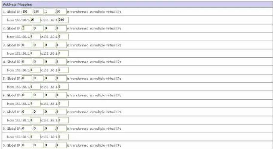
text_image
Address Mapping 1. Global IP: 192 168 1 10 is transformed as multiple virtual IPs from 192.160.1.10 c192.160.1 244 2. Global IP: 0 0 0 is transformed as multiple virtual IPs from 192.160.1.0 c192.160.1 0 3. Global IP: 0 0 0 is transformed as multiple virtual IPs from 192.160.1.0 c192.160.1 0 4. Global IP: 0 0 0 is transformed as multiple virtual IPs from 192.160.1.0 c192.160.1 0 5. Global IP: 0 0 0 is transformed as multiple virtual IPs from 192.160.1.0 c192.160.1 0 6. Global IP: 0 0 0 is transformed as multiple virtual IPs from 192.160.1.0 c192.160.1 0 7. Global IP: 0 0 0 is transformed as multiple virtual IPs from 192.160.1.0 c192.160.1 0 8. Global IP: 0 0 0 is transformed as multiple virtual IPs from 192.160.1.0 c192.160.1 0 9. Global IP: 0 0 0 is transformed as multiple virtual IPsNAT >> VIRTUAL SERVER
If you configure the Router as a virtual server, remote users accessing services such as web or FTP at your local site via public IP addresses can be automatically redirected to local servers configured with private IP addresses. In other words, depending on the requested service (TCP / UDP port number), the Router redirects the external service request to the appropriate server (located at another internal IP address).
In Figure 3, the Router configuration working as Virtual Server is shown.
FIGURE 3 Virtual Server Router configuration
Virtual Server
You can configure the router at a virtual server so that remote users accessing services such as the web or FTP at your local site via public IP addresses can be automatically redirected to local servers configured with private IP addresses. In other words, depending on the requested service (TCP/UDP port number), the router redirects the external service request to the appropriate server (located at another internal IP address). The tool can support both port ranges, multiple ports, and combinations of the two.
For example:
◆ Port Ranges: ex. 100-150
Multiple Ports ex. 25,110,80
Combination: ex-25-100.80
| No. | LAN IP Address | Protocol Type | LAN Port | Public Port | Enable | ||
| 1 | 192.168.1.10 | TCP | 24 | 38 | Add Clean | ||
| 2 | 192.168.1.25 | UDP | 32 | 39 | Add Clean | ||
| 3 | 192.168.1. | TCP | Add Clean | ||||
| 4 | 192.168.1. | TCP | Add Clean | ||||
| 5 | 192.168.1. | TCP | Add Clean | ||||
| 6 | 192.168.1. | TCP | Add Clean | ||||
| 7 | 192.168.1. | TCP | Add Clean | ||||
| 8 | 192.168.1. | TCP | Add Clean | ||||
| 9 | 192.168.1. | TCP | Add Clean | ||||
| 10 | 192.168.1. | TCP | Add Clean | ||||
| 11 | 192.168.1. | TCP | Add Clean | ||||
For example, if you set Type/Public Port to TCP/80 (http or web) and the Private IP/Port to 192.168.1.40/80 then all HTTP requests from outside users will be transferred to 192.168.1.40 on port 80. Therefore by just entering the IP address provided by the ISP, Internet users can access the service they need at the local address to which you redirect them.
The more common TCP service ports include:HTTP:80, FTP:21, Telnet:23 and POP3:110.
All list of ports is maintained at the following link:
http://www.iana.org/assignments/port-numbers.
NAT >> SPECIAL APPLICATION
Some applications do require multiple connections, such as Internet gaming, video conferencing and Internet telephony. These applications may not work when Networks Address Translation (NAT) is enabled. If you need to run applications that require multiple connections, use there screens to specify the additional public ports to be opened for each application.
Figure 4 shows the insertion of port (Trigger port) to open the inbound traffic for special applications.
FIGURE 4 Trigger port configuration for special application inbound traffic
Special Applications
Some applications require multiple connections, such as Internal gaming, video conferencing, Internal Naphony and other. These applications cannot work when Network Address Translation (NAT) is enabled. If you need to run applications that require multiple connections, specify the port normally associated with an application in the "Trigger Port" field, select the protocol type as TCP or UDP, then enter the public ports associated with the trigger port to open them for inbound traffic. Note: The range of the Trigger Ports is from 1 to 65535.
| Trigger Part | Trigger Type | Public Part | Public Type | Enabled | |
| 1. | [01] | TCP UCP | [089] | TCP UDP | ☑ |
| 2. | TCP UCP | TCP UDP | ☐ | ||
| 3. | TCP UCP | TCP UDP | ☐ | ||
| 4. | TCP UCP | TCP UDP | ☐ | ||
| 5. | TCP UCP | TCP UDP | ☐ | ||
| 6. | TCP UCP | TCP UDP | ☐ | ||
| 7. | TCP UCP | TCP UDP | ☐ | ||
| 8. | TCP UCP | TCP UDP | ☐ | ||
| 9. | TCP UCP | TCP UDP | ☐ | ||
| 10. | TCP UCP | TCP UDP | ☐ | ||
| Popular applications - select one - CDFY TO | |||||
HELP SAVE SETTINGS CANCEL
TABLE 2 List of fields on the Special Applications menu
| PARAMETER | DESCRIPTION |
| Trigger Port | Allows to open the inbound traffic for special application such as Internet gaming, video conferencing, Internet telephony and others. |
| Trigger Type | Select TCP or UDP protocol. |
| Public port | Port towards network. |
| Public Type | Select TCP or UDP protocol. |
| Enabled | Enable / Disable the Trigger port. |
| Popular applications | To quickly copy the entry to the table. |
NAT >> NAT MAPPING TABLE
This section displays the current NAPT (Network Address Port Translation) address mapping (see Figure 5).
© (2008) Pirelli Broadband Solutions S.p.A. All Rights Reserved. Proprietary Use Pursuant to Cover Page Instructions.
DISCUS™ DRG A124G
FIGURE 5 Network Address Port Translation table

text_image
NAT Mapping Table NAT Mapping Table displays the current NAPT address mappings. Index Protocol Local IP Local Port Pseudo IP Pseudo Port Peer IP Peer Port RefreshHELP
© (2008) Pirelli Broadband Solutions S.p.A. All Rights Reserved. Proprietary Use Pursuant to Cover Page Instructions.
DISCUS™ DRG A124G
This Page has been intentionally left blank
© (2008) Pirelli Broadband Solutions S.p.A. All Rights Reserved. Proprietary Use Pursuant to Cover Page Instructions.
Routing Section
This menu item is to define the routing related parameters including static routes and RIP parameters. Figure 1 shows the ROUTING main screen.
FIGURE 1 Routing main screen
Routing Settings
This page defines the routing related parameters including static routes and RIP parameters.
ROUTING >> STATIC ROUTE
The Static Route panel is intended for static routes configuration (see Figure 2).
FIGURE 2 Static Route Parameter configuration
Static Route Parameter
Please Enter the Following Configuration Parameters:
| Index | Network Address | Subnet Mark | Gateway | Configure |
| 1 | 10.18.19.0 | 255,255,255.0 | 0.0.0.0 | Edit Delete |
| 2 | 150.76.32.0 | 255,255,246.0 | 0.0.0.0 | Edit Delete |
| 3 | 10.57.0.0 | 255,255.0.0 | 0.0.0.0 | Edit Delete |
| 4 | 10.28.0.0 | 255,255.0.0 | 0.0.0.0 | Edit Delete |
Add route Add routes with V□ Gateway
HELP SAVE SETTINGS CANCEL
Click Add route button to set up a new static route entry.
© (2008) Pirelli Broadband Solutions S.p.A. All Rights Reserved. Proprietary Use Pursuant to Cover Page Instructions.
FIGURE 3 Static Route Parameter configuration (add new route)
Static Route Parameter
Please Enter the Following Configuration Parameters
| Index | Network Address | Subset Mask | Gateway | Configure |
| 1 | 10.10.10.0 | 255.255.255.0 | 0.0.0.0 | Edit Delete |
| 2 | 113.76.32.0 | 255.255.240.0 | 0.0.0.0 | Edit Delete |
| 3 | 10.57.0.0 | 255.255.0.0 | 0.0.0.0 | Edit Delete |
| 4 | 10.28.0.0 | 255.255.0.0 | 0.0.0.0 | Edit Delete |
| 5 | 10.29.3.0 | 255.255.255.0 | 0.0.0.0 | N/A |
HELP SAVE SETTINGS CANCEL
TABLE 1 List of fields on Address mapping menu
| PARAMETER | DESCRIPTION |
| Network Address | Enter the IP address of the remote computer for which to set a static route |
| Subnet Mask | The subnet mask of the destination network |
| Gateway | Enter the WAN IP address of the gateway to the remote network |
| Configure | Click Edit button to edit existing static route's parameters. By clicking the Delete button, the related entry will be removed |
ROUTING >> RIP
RIP (Routing Information Protocol) sends routing-update messages at regular intervals and when the network topology changes. When a router receives a routing update that includes changes to an entry, it updates its routing table to reflect the new route. RIP routers maintain only the best route to a destination. After updating its routing table, the router immediately begins transmitting routing updates to inform other network routers of the change.
FIGURE 4 RIP parameter configuration
RIP Parameter
Please Enter the following Configuration Parameters:
■ General RIP parameter
RIP Mode
○ Disable
Enable
Auto Summary
● disable
Enable
Table of current interface EIP parameter
| Interface | Operation Mode | Version | Poison Reverse | Authentication Required | Authentication Code |
| VLAN1(Default) | Enable | 1 | Enable | Password | **** |
| ATM1 | Disable | 1 | Disable | None | |
| ATM2 | Disable | 1 | Disable | None | |
| ATM3 | Disable | 1 | Disable | None | |
| ATM4 | Disable | 1 | Disable | None | |
| ATM5 | Disable | 1 | Disable | None | |
| ATM6 | Disable | 1 | Disable | None | |
| ATM7 | Disable | 1 | Disable | None | |
| ATM8 | Disable | 1 | Disable | None | |
| PPP+E1 | Disable | 1 | Disable | None | |
| PPP+E2 | Disable | 1 | Disable | None | |
| PPP+E3 | Disable | 1 | Disable | None |
The meaning of RIP parameters is explained in Table 2
TABLE 2 List of RIP parameter
| PARAMETER | DESCRIPTION |
| General RIP parameter | |
| RIP Mode | Select to globally enables or disables RIP |
| Auto Summary If Auto summary is disabled, then RIP packets will include sub-network information from all sub-networks connected to the router. If enabled, this sub-network information will be summarized to one piece of information covering all sub-networks | |
| Table of current interface RIP parameter | |
| Interface | Identify the WAN interface to be configured |
| Operation Mode | Is possible to set:Disable: RIP disable on this interfaceEnable: RIP enabled on this interfaceSilent: listens for route broadcasts and updates the route table. It does not participate in sending route broadcast |
Version Sets the RIP version to use on this interface
© (2008) Pirelli Broadband Solutions S.p.A. All Rights Reserved. Proprietary Use Pursuant to Cover Page Instructions.
TABLE 2 List of RIP parameter
| PARAMETER | DESCRIPTION |
| Poison Reverse A method for preventing loops that would cause endless retransmission of data trafficNone: NO authenticationPassword: A password authentication key is included in the packet. If doesn't match what is expected, the packet will be discarded. This method provides very little security as it is possible to learn the authentication key by watching RIP packets. | |
Authentication Required Password or MD5 Authentication key
ROUTING >>ROUTING TABLE
This menu item shows the list of configured routes (see Figure 5).
FIGURE 5 Routing Table
Routing Table
List Routing Tabl
| Flags | Network Address | Netmask | Gateway | Interface |
| C | 10.0.0.0 | 255.255.255.0 | Directly | ATM2 |
| C | 192.168.1.0 | 255.255.255.0 | Directly | VLAN1 |
| C | 127.0.0.1 | 255.255.255.255 | Directly | Loopback |
Flags : C - directly connected, S - static, R - RIP, I - ICMP Redirect
HELP
TABLE 3 List of fields on Routing Table inside Routing section
| PARAMETER | DESCRIPTION | |
| Flags | C= Direct connection on the same subnetS=Static routeR=RIP assigned routeI=ICMP (Internet Control Message Protocol) Redirect route | |
| Network address | Ad- | Destination IP address |
| Netmask | The sub-network associated with the destination. This is a template that identifies the address bits in the destination address used for routing to specific subnets. Each bit that corresponds to "1" is part of the subnet mask number; each bit that corresponds to "0" is part of the host number | |
| Gateway | The IP address of the router at the next hop to which frames are forwarded | |
| Interface | The local interface through which the next hop of this route is reached | |
© (2008) Pirelli Broadband Solutions S.p.A. All Rights Reserved. Proprietary Use Pursuant to Cover Page Instructions.
DISCUS™ DRG A124G
TABLE 3 List of fields on Routing Table inside Routing section
| PARAMETER | DESCRIPTION |
| Metric | When a router receives a routing update that contains a new or changed destination network entry, the router adds 1 to the metric value indicated in the update and enters the network in the routing table. |
© (2008) Pirelli Broadband Solutions S.p.A. All Rights Reserved. Proprietary Use Pursuant to Cover Page Instructions.
DISCUS™ DRG A124G
This Page has been intentionally left blank
© (2008) Pirelli Broadband Solutions S.p.A. All Rights Reserved. Proprietary Use Pursuant to Cover Page Instructions.
Firewall Section
The Router's firewall inspects packets at the application layer, maintains TCP and UDP session information including time-outs and the number of active sessions, and provides the ability to detect and prevent certain types of network attacks.
Network attacks that deny access to a network device are called Denial of Service (DoS) attacks. DoS attacks are aimed at devices and networks with a connection to the Internet. Their goal is not steal information, but to disable a device or network so users no longer have access to network resources.
The router protects against the following DoS attacks: IP Spoofing, Land Attack, Ping of Death, IP with zero length, Smurf attack, UDP port loopback, Snork Attack, TCP null scan and TCP SYN flooding.
The firewall doesn't significantly affect system performance, so we advise leaving it enabled to protect your network.
Select Enable radio button and select the SAVE SETTINGS button to open the firewall submenus (see Figure 1).
FIGURE 1 Enabling Firewall screen
Security Settings (Firewall)
The Device provides extensive firewall protection by restricting connection parameters to limit the risk of hacker attack, and defending against a wide array of common attacks. However, for applications that require unrestricted access to the Internet, you can configure a specific client/server as a demilitated zone (DMZ).

SAVE SETTINGS
© (2008) Pirelli Broadband Solutions S.p.A. All Rights Reserved. Proprietary Use Pursuant to Cover Page Instructions.
DISCUS™ DRG A124G
FIREWALL >> ACCESS CONTROL
ACCESS CONTROL menu item allows users to define the outgoing traffic permitted or not-permitted through the WAN interface. The default is to permit all outgoing traffic.
FIGURE 2 Access Control configuration on Firewall section
Access Control Access Control allows users to define the traffic type permitted or not-permitted to WAN port service. This page includes IP address filtering and MAC address filtering.

- Normal Filtering Table (up to 10 computers)
| Rule Description | Client FC IP Address | Client Service | Schedule Rule | Configure |
| E-banking | 192.150.1.10 + 31 | WWW, News Forums, AIM, DAG, SNMP | Always Blocking | Edit Delete |
Add PC
HELP SAVE SETTINGS CANCEL
TABLE 1 List of fields on Access Control command menu
PARAMETER
DESCRIPTION
Enable Filtering Function Click Yes to turn on the filtering function
Normal Filtering Table Displays a summary of the filtering rules configured
To add a PC to the filtering table:
- Click Add PC button on the Access Control screen
- Define the appropriate settings for client PC services
- Click OK button and then click SAVE SETTINGS button to save your settings.
FIGURE 3 Insertion of new access limitation on Access control
Access Control Add PC
This page allows users to define service limitations of client PCs, including IP address, service type and scheduling rule criteria. For the URL blocking function, you need to configure the URL address first on the "URL Blocking Site" page. For the scheduling function, you also need to configure the schedule rule first on the "Schedule Rule" page.
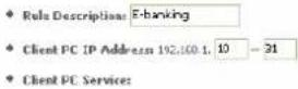
| Service Name | Detail Description | Blocking |
| WWW | HTTP, TCP Port 80, 3129, 8008, 8031, 8080 | ☑ |
| WWW with URL Blocking | HTTP (Ref: URL Blocking Site Page) | ☐ |
| E-mail Sending | SMTP, TCP Port 25 | ☐ |
| Newt Forums | NNTP, TCP Port 119 | ☑ |
| E-mail Receiving | POP3, TCP Port 110 | ☐ |
| Secure HTTP | HTTPS, TCP Port 443 | ☐ |
| File Transfer | FTP, TCP Port 21 | ☐ |
| Telnet Service | TCP Port 23 | ☐ |
| AIM | POL Instant Messenger, TCP Port 5150 | ☑ |
| MailMealing | HL229, TCP Port 1720, 1503 | ☐ |
| DNS | UDP Port 53 | ☑ |
| SNMP | UDP Port 161, 162 | ☑ |
| VPN-PPTP | TCP Port 1723 | ☐ |
| VPN-L2TP | UDP Port 1701 | ☐ |
| TCP | All TCP Port | ☐ |
| UDP | All LDP Port | ☐ |
FIREWALL >> MAC FILTER
The Router can also limit the access of hosts within the local area network (LAN). The MAC Filtering Table allows the Router to enter up to 32 MAC addresses that are not allowed access to the WAN port. Please note that this filter only applies to Ethernet clients.
FIGURE 4 MAC Filter configuration on MAC Filter Table command
MAC Filtering Table
This section helps provides MAC Filter configuration. When enabled, only MAC addresses configured will have access to your network. All other client devices will get denied access. This security feature can support up to 32 devices and applies to clients.

* MAC Filtering Table (up to 32 computers)
© (2008) Pirelli Broadband Solutions S.p.A. All Rights Reserved. Proprietary Use Pursuant to Cover Page Instructions.
DISCUS™ DRG A124G
The meaning of fields is shown in Table 2
TABLE 2 List of fields on the MAC Filtering Table
| PARAMETER | DESCRIPTION |
| MAC Address Control | Select to enable or disable this function |
| MAC Filtering Table | Enter the MAC address in the space provided |
| DHCP Client List | Use this drop down menu to quickly copy the currently associated clients to the table |
The Router allows the user to block access to web sites by entering either a full URL address or just a keyword. This feature can be used to protect children from accessing violent or pornographic web sites.
FIGURE 5 URL Blocking menu
| Rule Number | URL / Keyword | Rule Number | URL / Keyword |
| Site 1 | www.gmail.com | Site 16 | |
| Site 2 | Site 17 | ||
| Site 3 | Site 18 | ||
| Site 4 | Site 19 | ||
| Site 5 | Site 20 | ||
| Site 6 | Site 21 | ||
| Site 7 | Site 22 | ||
| Site 0 | Site 23 | ||
| Site 9 | Site 24 | ||
| Site 10 | Site 25 | ||
| Site 11 | Site 26 | ||
| Site 12 | Site 27 | ||
| Site 13 | Site 28 | ||
| Site 14 | Site 29 | ||
| Site 15 | Site 30 |
It is possible to define up to 30 sites here.
FIREWALL >> SCHEDULE RULE
It is possible to filter Internet access for local clients based on rules. Each access control rule may be activated at a scheduled time.
Define the schedule on the Schedule Rule screen and apply the rule on the Access Control screen.
© (2008) Pirelli Broadband Solutions S.p.A. All Rights Reserved. Proprietary Use Pursuant to Cover Page Instructions.
FIGURE 6 Schedule Rule
Schedule Rule
This page defines schedule rule names and activates the schedule for use in the "Access Control" page.
♦ Schedule Rule Table (up to 10 rules)
| Role Name | Role Comment | Configure |
| Site blocking | for Privacy | Edit Delete |
Add Schedule Rule
HELP SAVE SETTINGS CANCEL
Follow this steps to add a schedule rule:
- Select the Add Schedule Rule item on the Schedule Rule screen
- Define the appropriate settings for a schedule rule
- Click OK button and then click SAVE SETTINGS button to save your settings.
FIGURE 7 Editing of Schedule Rule
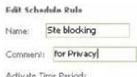
| Week Day | Start Time (hhmm) | End Time (hhmm) |
| Every Day | 9 : 00 | 10 : 00 |
| Sunday | □ : □ | □ : □ |
| Monday | □ : □ | □ : □ |
| Tuesday | □ : □ | □ : □ |
| Wednesday | □ : □ | □ : □ |
| Thursday | □ : □ | □ : □ |
| Friday | □ : □ | □ : □ |
| Saturday | □ : □ | □ : □ |
OK Cancel
FIREWALL >> INTRUSION DETECTION
It is used to detect and block common hacker attacks. The main firewall feature is SPI (Stateful Packet Inspection) that supports many applications that are using port numbers. In this section menu there is some fields:
• Intrusion Detection Feature
Intrusion Detection Stateful Packet Inspection (SPI) and Anti-DoS firewall protection (Default: Enabled)
The Intrusion Detection Feature of the Router limits access for incoming traffic at the WAN port. When the SPI feature is turned on, all incoming traffic at the WAN port will be blocked except for those types marked in the Stateful Packet Inspection
DISCUS™ DRG A124G
section
RIP Defect (Default: Disabled)
If an RIP request packet is not acknowledged to by the router, it will stay in the input queue and not be released. Accumulated packets could cause the input queue to fill, causing severe problems for all protocols. Enabling this feature prevents the packets from accumulating.
Discard Ping to WAN (Default : Enabled)
Prevent a ping on the Router's WAN port from being routed to the network.
• Stateful Packet inspection
It's called a "stateful" packet inspection because it examines the contents of the packet to determine the state of the communications; i.e., it ensures that the started destination computer has previously requested the current communication. This is a way of ensuring that all communications are initiated by the recipient computer and are taking place only with sources that are known and trusted from the previous interactions. In addition to being more rigorous in their inspection of packets, stateful inspection firewalls also close off ports until connection to the specific port is requested.
When particular types of traffic are checked, only the particular type of traffic initiated from the internal LAN will be allowed. For example, if the user only checks "FTP service" in the Stateful Packet Inspection section, all incoming traffic will be blocked except for FTP connections initiated from the local LAN.
Stateful Packet Inspection allows you to select different application types that are using dynamic ports numbers. If you wish to use the Stateful Packet Inspection (SPI) to block packets, click on the Yes radio button in the inspection type that you need, such as Packet Fragmentation, TCP connection, UDP Session, FTP Service, H.323 Service, or TFTP Service.
FIGURE 8 Intrusion detection panel
Intrusion Detection
When the SPI (Stateful Packet Inspection) firewall feature is enabled, all packets can be blocked. Stateful Packet Inspection (SPI) allows full support of different application types that are using dynamic port numbers. For the applications checked in the list below, the Device will support full operation as initiated from the local LAN.
The Device firewall can block common hacker attacks, including IP Spoofing, Land Attack, Ping of Death, IP with zero length, Smart Attack, UDP port loopback, Snork Attack, TCP null scan, and TCP STN flooding.
◆ Intrusion Detection Feature
| SPI and Anti DoS firewall protection | ☑ |
| RIP defect | ☐ |
| Discard Ping To WAN Interface | ☑ |
◆ Stateful Packet Inspection
| Packet Fragmentation | |
| TCP Connection | |
| UDP Session | |
| FTP Service | |
| H.323 Service | |
| IFTP Service |
When hackers attempt to enter your network, we can alert you by e-mail
| Your E-mail Address : user@libero.it |
| SMTP Server Address : smtp.user@libero.it |
| POP3 Server Address : pop3.user@libero.it |
| User name : Test |
Scroll down to view more information.
- When hackers attempt to enter your network, we can alert you by e-mail.
Enter your email address. Specify your STMP and POP3 servers, username and password.
- Connection Policy
Enter the appropriate values for TCP / UDP sessions as described in the following table.
TABLE 3 List of values TCP/UDP sessions
| PARAMETER | DEFAULTS | DESCRIPTION |
| Fragmentation half-open wait 10 s Configures the number of seconds that a packet state structure remains active.When the timeout value expires the router drops the unassembled packet, freeing that structure for use by another packet | ||
| TCP SYN wait 30 s Defines how long the software will wait fora TCP session to synchronize before dropping the session | ||
| TCP FIN wait 5 s Specifies how long TCP session will bemaintained after the firewall detects a FIN packet | ||
© (2008) Pirelli Broadband Solutions S.p.A. All Rights Reserved. Proprietary Use Pursuant to Cover Page Instructions.
TABLE 3 List of values TCP/UDP sessions
| PARAMETER | DEFAULTS | DESCRIPTION |
| TCP connection idle timeout 3600 s | The length of time for which a TDP session will be managed if there is no activity | |
| UDP session idle timeout 30 s | The length of time for which a UDP session will be managed if there is no activity | |
| H.323 data channel idle timeout 180 s | The length of time for which a H.323 session will be managed if there is no activity |
- DoS criteria and port scan criteria
Set up DoS and port scan criteria in the spaces provided (as shown in Table 4)
TABLE 4 List of values of DoS parameters
| PARAMETER | DEFAULTS | DESCRIPTION |
| Total incomplete TCP / UDP session HIGH | 300 sessions | Defines the rate of new unestablished session that will cause the software to start deleting half-open sessions |
| Total incomplete TCP / UDP session LOW | 250 sessions | Defines the rate of new unestablished sessions that will cause the software to stop deleting half open sessions |
| Total incomplete TCP / UDP session (per min) HIGH | 250 sessions | Maximum number of allowed incomplete TCP / UDP sessions per minute |
| Total incomplete TCP / UDP session (per min) LOW | 200 sessions | Minimum number of allowed incomplete TCP / UDP sessions per minute |
| Incomplete TCP / UDP sessions detect sensitive time period | 300 msec | Length of time before an incomplete TCP / UDP session from the same host |
| Maximum half-open fragmentation packet number from same host | 30 | Maximum number of half-open fragmentation packets from the same host. |
| Half-open fragmentation detect sensitive time period | 10000 msec | Length of time before a half-open fragmentation session is detected as half-open |
| Flooding cracker block time | 300 s | Length of time from detecting a flood attack to blocking attack |

The firewall does not significantly affect system performance, so we advise enabling the prevention features and leaving them at the default settings to protect your network
© (2008) Pirelli Broadband Solutions S.p.A. All Rights Reserved. Proprietary Use Pursuant to Cover Page Instructions.
DISCUS™ DRG A124G
FIREWALL >> DMZ
If you have a client PC that cannot run an Internet application properly from behind the firewall, you can open the client up to unrestricted two-way Internet access. Enter the IP address of a DMZ (Demilitarized Zone) host this screen. Adding a client to the DMZ may expose your local network to a variety of security risks, so only use this option as a last resort.
FIGURE 9 DMZ settings
DMZ(Demilitarized Zone)
If you have a local client PC that cannot run an Internet application properly from behind the NAT firewall, then you can open the client up to unrestricted two-way Internet access by defining a Virtual DM2 Host.

Multiple PCs can be exposed to the Internet for two way communications e.g. Internet gaming, video conferencing, or VPN connections. To use the DME, you must set a static IP address for that PC.
| Public IP Address | Client PC IP Address | |||||||
| 1. | 0,0,0,0 | 192.168.1 | 0 | |||||
| 2. | 192 | 168 | 10 | 11 | 192.168.1 | 10 | ||
| 3. | 0 | 0 | 0 | 0 | 192.168.1 | 0 | ||
| 4. | 0 | 0 | 0 | 0 | 192.168.1 | 0 | ||
| 5. | 0 | 0 | 0 | 0 | 192.168.1 | 0 | ||
| 6. | 0 | 0 | 0 | 0 | 192.168.1 | 0 | ||
| 7. | 0 | 0 | 0 | 0 | 192.168.1 | 0 | ||
| 8. | 0 | 0 | 0 | 0 | 192.168.1 | 0 | ||
HELP SAVE SETTINGS CANCEL
© (2008) Pirelli Broadband Solutions S.p.A. All Rights Reserved. Proprietary Use Pursuant to Cover Page Instructions.
DISCUS™ DRG A124G
This Page has been intentionally left blank
© (2008) Pirelli Broadband Solutions S.p.A. All Rights Reserved. Proprietary Use Pursuant to Cover Page Instructions.
SNMP Section
Use the SNMP configuration screen to display and modify parameters for the Simple Network Management Protocol (SNMP). Figure 1 shows SNMP main screen.
FIGURE 1 SNMP Main panel
SNMP Setting The Device provider: SNMP setting for community and trap information.


SNMP >> COMMUNITY
A computer attached to the network, called a Network Management Station (NMS), can be used to access this information. Access rights to the agent are controlled by community strings. To communicate with the Router, the NMS must first submit a valid community string for authentication.
Figure 2 shows the SNMP community configuration.
© (2008) Pirelli Broadband Solutions S.p.A. All Rights Reserved. Proprietary Use Pursuant to Cover Page Instructions.
FIGURE 2 SNMP community settings
SNMP Community
In the context of SNMP, a relationship between an agent and a set of SNMP managers defines security characteristics. The community concept is a local one, defined at the agent. The agent establishes one community for each desired combination of authentication, access control, and proxy characteristics. Each community is given a unique (within this agent) community name, and the management stations within that community are provided with and must employ the community name in all get operations. The agent may establish a number of communities, with overlapping management station membership.
| No. | Community | Access | Valid |
| 1 | public | Read | ✓ |
| 2 | private | Write | ✓ |
| 3 | Read | □ | |
| 4 | Read | □ | |
| 5 | Read | □ |
HELP SAVE SETTINGS CANCEL
The meaning of fields is explained in Table 1.
TABLE 1 List of SNMP community fields
| PARAMETER | DESCRIPTION |
| Community | A community name authorized for management access |
| Access | Management access is restricted to Read Only (Read) or Read / Write (Write) |
| Valid | Enables / Disables the entry |

Up to five community names may be entered.
SNMP >> TRAP
Specify the IP address of the NMS to notify when a significant event is detected by the agent. When a trap condition occurs, the SNMP agent sends an SNMP trap message to any NMS specified as a trap received.
Figure 3 shows SNMP Trap configuration.
© (2008) Pirelli Broadband Solutions S.p.A. All Rights Reserved. Proprietary Use Pursuant to Cover Page Instructions.
DISCUS™ DRG A124G
FIGURE 3 TRAP configuration panel
SNMP Trap
In the context of SNMP, an unsolicited message can be sent by an agent to management station. The purpose is to notify the management station of some unusual event.
| No. | IP Address | Community | Version | |||
| 1 | 192 | 164 | 10 | 33 | Public | V2c |
| 2 | 0 | 0 | 0 | 0 | Disabled | |
| 3 | 0 | 0 | 0 | 0 | Disabled | |
| 4 | 0 | 0 | 0 | 0 | Disabled | |
| 5 | 0 | 0 | 0 | 0 | Disabled | |

Table 2 Table 2 shows the meaning of SNMP trap menu.
TABLE 2 List of parameters on SNMP trap menu
| PARAMETER | DESCRIPTION |
| IP Address | Traps are sent to this address when errors or specific events occur on the network |
| Community | A community string (password) specified for trap management.Enter a word, something other than public or private, to prevent unauthorized individuals from accessing information on your system |
| Version | Sets the trap status to disabled, or enabled with V1 or V2cThe V2c protocol was proposed in late 1995 and includes enhancements to V1 that are universally accepted. These include a get-bulk command to reduce network management traffic when retrieving a sequence of MIB variables, and a more elaborate set of error codes for improved reporting to a Network Management Station |
© (2008) Pirelli Broadband Solutions S.p.A. All Rights Reserved. Proprietary Use Pursuant to Cover Page Instructions.
DISCUS™ DRG A124G
This page has been intentionally left blank
© (2008) Pirelli Broadband Solutions S.p.A. All Rights Reserved. Proprietary Use Pursuant to Cover Page Instructions.
UPnP Section
The Universal Plug and Play architecture offers pervasive peer-to-peer network connectivity of PCs of all form factors, intelligent appliances, and wireless devices. UPnP enables seamless proximity network in addition to control and data transfer among networked devices in the office, home and everywhere within your network.
Figure 1 shows the UPnP menu item.
FIGURE 1 Universal Plug and Play (UPnP) menu
UPnP(Universal Plug and Play) Setting
The Universal Plug and Play architecture offers pervasive peer-to-poor network connectivity of PCs of all form factors, intelligent appliances, and wireless devices. LPnP enables seamless proximity network in addition to control and data transfer among networked devices in the home, office and everywhere in between.

HELP SAVE SETTINGS CANCEL
© (2008) Pirelli Broadband Solutions S.p.A. All Rights Reserved. Proprietary Use Pursuant to Cover Page Instructions.
DISCUS™ DRG A124G
UPnP allows the device to automatically:
- join a network
- obtain IP address
- convey its capabilities and learn about the presence and capabilities of other devices
Select the Enable radio button and the click on SAVE SETTINGS button to activate the function.
QoS Section
The QoS (Quality of Service) function allows you to differentiate traffic types and provide high-priority forwarding service for applications such as VOIP or gaming.
By means of this menu item, it will be possible to classify traffic of applications and to provide them with differentiated services (see Figure 1).
FIGURE 1 QoS Settings Main panel
QoS Settings
The bandwidth gap between LAN and WAP may significantly degrade performance of critical network applications, such as Vo3F, gaming, and VPN. This QoS function allows users to classify traffic of applications and provides them with differentiated services (Diffenv).
| Enable or disable QoS module function : | ○ Enable | ○ Disable |
Diffserv Forwarding Groups:
Below show the Different forwarding behaviors this router supports. User can further configure the bandwidth allocation of each forwarding behavior
| Name | Description | Priority | Bandwidth Allocation | |
| Minimum | Allow More | |||
| BE | Best Effort forwarding | Lowest | 75% | ☑ |
| AF1a | Low | 5% | ☑ | |
| AF2a | Attuned Forwarding, provide delivery of packets in four independently forwarded AF classes. Within each AF class, an IP packet can be assigned one of three different levels of drop precedence. | High | 5% | ☑ |
| AF3a | 3% | ☑ | ||
| AF4a | 2% | ☑ | ||
| EF | Expected Forwarding, is intended to provide low delay, low jitter and low lost delivery of packets. | Highest | 10% | ☑ |
HELP SAVE SETTINGS CANCEL
In Table 1 a list of parameters present on the QoS Settings panel is shown.
© (2008) Pirelli Broadband Solutions S.p.A. All Rights Reserved. Proprietary Use Pursuant to Cover Page Instructions.
TABLE 1 List of parameters on QoS Settings menu
| PARAMETER | DESCRIPTION |
| Enable or disable QoS module function | Check to enable or disable this function |
| BE | Best Effort forwarding, set the percentage for this type of QoS. |
| AF1x | Set the percentage for four different types of Assured Forwarding. |
| AF2x | |
| AF3x | |
| AF4x | |
| EF | Expedited Forwarding, is intended to provide lo delay, low jitter and low loss delivery of packets |
QoS >> TRAFFIC MAPPING
This panel is to classify traffic into Diffserv forwarding groups and outgoing VCs. Figure 2 shows Traffic Mapping panel where a set of applied rules is listed.
FIGURE 2 Traffic Mapping menu
Traffic Mapping
Up to 16 rules can be defined to classify traffic into Different forwarding groups and outgoing VCs.
| Fula Noma | Traffic Description | Map to Difizure | Outgoing VC | Configure. | |
| Festa | SNVP | BE | by routing | Edit | Del |
HELP
Click Add traffic class button to add a new traffic class. Figure 3 shows insertion of a new traffic class.
FIGURE 3 Editing / insertion of Traffic Class
Edit Traffic Class
This page is for user to specify a classify rule. First, define the class by the traffic type and the local and remote addresses. Then set the Diffserv forwarding group this class is mapped to. Finally, select the outgoing VC that traffic of this class would be routed to.
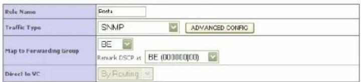
text_image
Rule Name Costs Traffic Type SNMP ADVANCED CONFIG Map to Forwarding Group BE Remark DSCP at BE (000000(00) Direct to VC By RoutingHELP Apply CANCEL
© (2008) Pirelli Broadband Solutions S.p.A. All Rights Reserved. Proprietary Use Pursuant to Cover Page Instructions.
DISCUS™ DRG A124G
QoS >> TRAFFIC STATISTICS
This screen shows the WAN outbound traffic statistics of all the Diffserv forwarding groups in the least 12 hours.
Figure 4 shows a traffic statistics by graphics.
FIGURE 4 Traffic Statistics graphic report menu
Traffic Statistics This page shows the WAN outbound traffic statistics of all the Diffserv forwarding groups in the last 12 hours (automatically update every 5 mins).
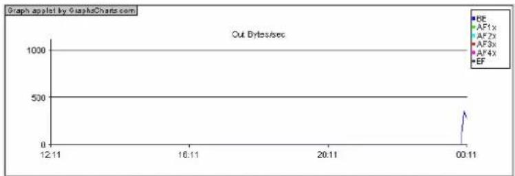
line
| Time | Out Bytes/sec | | ------ | ------------- | | 00:11 | 500 |
line
| Time | Drop Bytes/sec | | ------ | -------------- | | 12:11 | 0 | | 16:11 | 0 | | 20:11 | 0 | | 00:11 | 0 |HELP Refresh
Click Refresh button to renew the graphics.
© (2008) Pirelli Broadband Solutions S.p.A. All Rights Reserved. Proprietary Use Pursuant to Cover Page Instructions.
DISCUS™ DRG A124G
This Page has been intentionally left blank
© (2008) Pirelli Broadband Solutions S.p.A. All Rights Reserved. Proprietary Use Pursuant to Cover Page Instructions.
ADSL Section
ADSL (Asymmetric Digital Subscriber Line) is designed to deliver more bandwidth downstream (from the central office to the customer site) than upstream. This section (see Figure 1) is used to configure ADSL operation type and shows the ADSL status.
FIGURE 1 ADSL Parameter panel
ADSL Parameters and Status
This page displays ADSL-related parameters and status.
ADSL >> PARAMETERS
The menu item allows you to specify the ADSL standards to operate with. You may explicitly set a specific standard, or choose "Automatic" to automatically negotiate with remote DSLAM.
Figure 2 shows the ADSL standards selection on ADSL Parameter menu.
FIGURE 2 ADSL Parameter panel
ADSL Parameter
This page allows you to specify the ADSL standards to operate with. You may explicitly set a specific standard, or choose "Automatic" to automatically negotiate with remote DSLAM.


© (2008) Pirelli Broadband Solutions S.p.A. All Rights Reserved. Proprietary Use Pursuant to Cover Page Instructions.
DISCUS™ DRG A124G
Table 1 explains the meaning of values on the ADSL parameter menu.
TABLE 1 Operation modes (ADSL)
| PARAMETER | DESCRIPTION | |
| Operation Mode | AutomaticT1.413 Issue 2G.992.1 (G.DMT)G.992.3 (ADSL2)G.992.5 (ADSL2+) | |
ADSL >> STATUS
The Status screen displays information on connection line status, data rate, operation data, defect indication and statistics.
FIGURE 3 ADSL Status panel
| Configured | Currenal | |
| Line Status | --- | HAND/SHAKE |
| Link Type | --- | Fast Path |
Scroll down to view more information.
TABLE 2 List of parameter on ADSL status menu
| PARAMETER | DESCRIPTION |
| Status | |
| Line status | Shows the current status of the ADSL line connection |
© (2008) Pirelli Broadband Solutions S.p.A. All Rights Reserved. Proprietary Use Pursuant to Cover Page Instructions.
TABLE 2 List of parameter on ADSL status menu
| PARAMETER | DESCRIPTION |
| Link type Shows the type of link | |
| Data Rate | |
| Upstream | Maximum upstream data rate |
| Downstream Minimum downstream data rate | |
| Operation Data / Defect Indication | |
| Noise Margin | Maximum upstream and downstream noise margin |
| Attenuation | Maximum reduction in the strength of the upstream and downstream signal |
| Fast Path FEC Correction There are two latency paths that may be used: fast and interleaved. For either path, a forward error correction (FEC) scheme is employed to ensure higher data integrity.For maximum noise immunity, an interleaver may be used to supplement FEC | |
| Fast Path CRC Error The number of Fast Path Cyclic Redundancy Check errors | |
| Interleaved Path CRC Error The number of Interleaved Path Cyclic Redundancy Check errors | |
| Loss of Signal Defect Momentary signal discontinuities | |
| Fast Path HEC Error Fast Path Header Error Concealment errors | |
| Interleaved Path HEC Error Interleaved Path Header Error Concealment errors | |
| Statistics | |
| Received Cells | Number of cells received |
| Transmitted Cells | Number of cells transmitted |
© (2008) Pirelli Broadband Solutions S.p.A. All Rights Reserved. Proprietary Use Pursuant to Cover Page Instructions.
DISCUS™ DRG A124G
This Page has been intentionally left blank
© (2008) Pirelli Broadband Solutions S.p.A. All Rights Reserved. Proprietary Use Pursuant to Cover Page Instructions.
DDNS Section
This section is intended to describe the use and settings of DDNS functionality: DDNS indeed allows for the external and dynamic updating of a specified zone by other hosts or processes. The router can send a record update to the appropriate DNS server based on a DHCP client's NetBIOS name. The update occurs after the IP address lease is negotiated and is removed when the lease expires.
By selecting DDNS menu item (see Figure 1), it will be possible to map a static Domain Name to a dynamic IP address. To get advantage of this feature, it is necessary to get an account, a password and a static domain name from a DDNS Service Provider (this router supports DDNS services from www.dyndns.org and www.tzo.com).
FIGURE 1 DDNS Panel
DDNS (Dynamic DNS) Settings
DDNS allows users to map a static Domain Name to a dynamic IP address. However, You must get an account, password, and your static Domain Name from a DDNS service provider. This router supports DDNS services from www.dyndns.org and www.tzo.com.
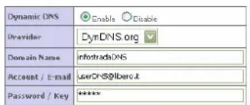
text_image
Dynamic DNS Enable Disable Provider DynDNS.org Domain Name InfotradeDNS Account / E-mail UserDNS@libero.it Password / Key *****HELP SAVE SETTINGS CANCEL
Upon DDNS Service Provider account creation, check the Enable radio button, choose the Provider name from the Provider list box and fill properly the Domain Name, the Account / E-mail and Password / Key fields.
© (2008) Pirelli Broadband Solutions S.p.A. All Rights Reserved. Proprietary Use Pursuant to Cover Page Instructions.
DISCUS™ DRG A124G
Upon SAVE SETTINGS button selection and Service Provider authentication, the DDNS functionality will be active.
Tools Section
This section is intended to describe the use of a set of tools conceived to manage the backup, the restore, the reset and the upgrade of the router's firmware by means of the Configuration Tools, Firmware Upgrade and Reset submenus.
FIGURE 1 Tools Main panel
Tools Settings
This page allows you to backup, restore, reset, and upgrade the router's firmware.
TOOLS >> CONFIGURATION TOOLS
By selecting Tools >> Configuration Tools menu item (see Figure 1), it will be possible to execute backup and restore tasks upon proper radio button selection:
- "Backup Router Configuration": by selecting this radio button, it will be possible to backup the router's current configuration to a file named "backup.bin" on your PC. To do so, select at first the Next>> button and then the Save button to save on a PC folder of your choice where to save the backup.bin file.
- "Restore from saved Configuration file (backup.bin)": by selecting this radio button, it will be then possible to restore a previously saved configuration (from a backup.bin file) to the router. Select the Next>> button and the enter the path and name of the backup.bin file or use the Browse... button to browse your PC folders. Upon proper backup.bin folder selection, do press the APPLY button: a prompt message will ask for restore confirmation.
DISCUS™ DRG A124G
- "Restore router to Factory Defaults": by selecting this radio button, it will be possible to force the router to perform a power reset and restore the original factory settings. Do select the APPLY button: a prompt message box will ask you for restore to Factory defaults confirmation.
FIGURE 2 Configuration Tools panel
Configuration Tools
Use the "Backup" tool to save the router's current configuration to a file named backup bin on your PC. You can then use the "Restore" tool to restore the saved configuration to the router. Alternatively, you can use the "Restore to Factory Defaults" tool to force the router to perform a power reset and restore the original factory settings.
Backup Router Configuration
○ Ractors from saved Configuration Re (backup.bin)
Restore router to Factory Defaults
Next >>
TOOLS >> FIRMWARE UPGRADE
By selecting Tools >> Firmware Upgrade menu item (see Figure 3), it will be possible to upgrade the router firmware using a file provided by the manufacturer.
Enter the path and firmware file name, or select the Browse... button to browse your PC folders; then click the BEGIN UPGRADE button. A prompt message box will ask you to confirm the upgrade process.
FIGURE 3 Firmware Upgrade panel
Fernazara Upgrade
This tool allows you to upgrade the router firmware using a file provided by us. You can download the latest firmware from the related website
Enter the path and name, or browse to the location, of the upgrade He then click the APPLY button. You will be prompted to confirm the upgrade to complete the process.


TOOLS >> RESET
By selecting Tools >> Reset menu item (see Figure 4), it will be possible, in the case the router stops responding correctly or in some way stops working properly, to perform a reset. Router's settings will not be changed.
To perform the reset, click on the REBOOT ROUTER button below. You will be asked to confirm your decision. The reset will be completed when the power light stops blinking.
FIGURE 4 Reset panel
Reset
In the event that the system stops responding correctly or in some way stops functioning, you can perform a reset. Your settings will not be changed. To perform the reset, click on the APPLY button below. You will be asked to confirm your decision. The reset will be complete when the power light stops blinking.

© (2008) Pirelli Broadband Solutions S.p.A. All Rights Reserved. Proprietary Use Pursuant to Cover Page Instructions.
Status Section
This section is intended to present the connection status for Device's WAN/LAN interfaces, firmware and hardware version numbers, any illegal attempts to access your network, as well as information on all DHCP client PCs currently connected to your network.
In the page a first Status area (see Figure 1) gives information on:
- Current Time: it reflects the time and date of the page displayed;
- INTERNET: it displays WAN connection type and status;
- GATEWAY: it displays system IP settings, as well as DHCP, NAT and Firewall status;
- INFORMATION: it displays the number of connected clients, as well as Device's hardware and firmware version numbers.
FIGURE 1 Status Panel
Status
You can use the Status screen to see the connection status for the router's WAN/LAN interface, firmware and hardware version numbers, any illegal attempts to access your network, as well as information on all DHCP client PCs currently connected to your network.
Current Time: 08/01/2003 00:34:36 am
INTERNET
ADSL: DISCONNECTED
GATEWAY
IP Address: 192.168.1.1
Subnet Mask: 255.255.255.0
DHCP Server: Enabled
Firewall: Enabled
UPnP: Enabled
Wireless: Enabled
INFORMATION
Number of DHCP Clients: 1
Runtime Code Version
1_095-W (Mar 26 2008 15:04:32)
Bool Code Version: V1.10.0
ADSL Modem Code Version: E.25.41.14 A
LAN MAC Address: 00-1C-A2-D9-B2-E0
Wireless MAC Address: 00-1C-A2-D9-B2-E0
Hardware Version 01
Serial Num: 71271Y0000085
The LAN Status area (see Figure 2) is used to show for each LAN port the Link, Speed and Duplex Status.
© (2008) Pirelli Broadband Solutions S.p.A. All Rights Reserved. Proprietary Use Pursuant to Cover Page Instructions.
FIGURE 2 LAN Status Panel
LAN Status
| Port No. | Link | Speed | Duplex |
| LAN1 | UP | 100 | FULL |
| LAN2 | DOWN | ||
| LAN3 | DOWN | ||
| LAN4 | DOWN |
The ATM PVC area (see Figure 3) shows, for each enabled VC, its configuration: VPI/VCI, Encapsulation, Protocol, IP Address, Subnet Mask, Gateway, Primary DNS and Secondary DNS.
FIGURE 3 ATM PVC Panel
ATM PVC
| VC1 | VC2 | |||
| VPI/VC1 | R/GE | VPI/VC1 | R/GE | |
| Encapsulation | LLC | Encapsulation | LLC | |
| Protocol | D00eE | Protocol | MAC Encapsulated Routing | |
| IP Address | Down | IP Address | 0,0,0,0 | |
| Subnet Mask | --- | Subnet Mask | 255,255-255,0 | |
| Gateway | --- | Gateway | 0,0,0,0 | |
| Primary DNS | --- | Primary DNS | --- | |
| Secondary DNS | --- | Secondary DNS | --- | |
| VC3 | VC4 | ||||
| VPI/VC1 | 8/21 | VPI/VC1 | 8/22 | ||
| Encapsulation | VC MLX | Encapsulation | VC MLX | ||
| Protocol | PPFoA | Protocol | 1403 Routing | ||
| IP Address | Down | IP Address | 0.0.0.0 | ||
| Subnet Mask | --- | Subnet Mask | 255,255,255.0 | ||
| Gateway | --- | Gateway | 0.0.0.0 | ||
| Primary DNS | --- | Primary DNS | --- | ||
| Secondary DNS | --- | Secondary DNS | --- | ||
| VCS | |
| UPI/ACI | 6/26 |
| Encapsulation | VC PIUX |
| Protocol | 1403 Bridging |
| IP Address | 192.168.1.1 |
| Subnet Mask | 255.255.255.0 |
| Gateway | 0.0.0.0 |
| Primary DNS | --- |
| Secondary DNS | --- |
The top bottom area (see Figure 4) displays information on:
- Security Log: attempts' list to gain access to local network. Shown data log can be saved, cleared or refreshed through related buttons.
- DHCP Client Log: LAN DHCP clients' list currently connected to the router. For each DHCP Client, the assigned IP address, the MAC Address and its friendly name are reported.
DISCUS™ DRG A124G
FIGURE 4 Security and DHCP Client Log Panel
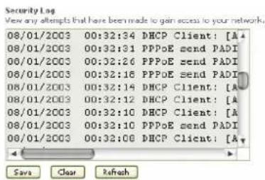
text_image
Security Log View any attempts that have been made to gain access to your network. 08/01/2003 00:32:34 DHCP Client: [A] 08/01/2003 00:32:31 PPPoE send PADI 08/01/2003 00:32:26 PPPoE send PADI 08/01/2003 00:32:16 PPPoE send PADI 08/01/2003 00:32:14 DHCP Client: [A] 08/01/2003 00:32:12 DHCP Client: [A] 08/01/2003 00:32:10 DHCP Client: [A] 08/01/2003 00:32:10 PPPoE send PADI 08/01/2003 00:32:06 DHCP Client: [A]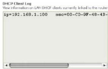
text_image
DHCP Client Log View information on LAN DHCP clients currently linked to the router ip=192.168.1.100 mac=00-C0-9F-48-4B-HELP
© (2008) Pirelli Broadband Solutions S.p.A. All Rights Reserved. Proprietary Use Pursuant to Cover Page Instructions.
DISCUS™ DRG A124G
This Page has been intentionally left blank
© (2008) Pirelli Broadband Solutions S.p.A. All Rights Reserved. Proprietary Use Pursuant to Cover Page Instructions.
Important Safety Information
This appendix contains directions that you must follow for your personal safety.
Follow all directions carefully. You must read the following safety information carefully before you install or remove the unit.

- Use only the power adapter that is supplied with the unit. The use of an alternative adapter can damage the Router and invalidate the warranty.
- Use an electrical outlet within easy distance and do not damage the power cable.
- To avoid electrical shock, do not open the Router.
- To prevent fire or shock hazard, do not expose your Router to rain or moisture, liquid and toxic substances.
- Particular care must be taken during installation and removal of cables and telephone line.
- Never touch uninsulated telephone wire or terminals unless the telephone line has been disconnected at the network interface.
- Ensure the correct ventilation to the Router. Do not obstruct the air conducts and do not lean anything over.
- Verify to place the Router out of direct sunlight and away from sources of heat.
- Avoid using your Router during an electrical storm.
- The Router generates and uses Radio Frequency (RF) energy. In some environments, the use of RF energy is not permitted. The user should seek local advice on whether or not RF energy is permitted within the area of intended use.

The crossed-out wheeled bin symbol on this electric or electronic equipment, or on its packaging, indicates that, at the end of its life, it must not be disposed of as unsorted household waste. Instead it must be separately collected.
As a consumer you must, therefore, use the specific collection schemes and, in particular, the municipal collection schemes provided for waste electrical and electronic equipment.
The separate collection and appropriate treatment of the equipment at the time of disposal helps to conserve natural resources and to ensure that it is recycled in a manner that protects human health and the environment from materials, components and substances that can be dangerous to the environment and harmful to human health.
Furthermore, the separate collection and appropriate treatment of the equipment, at the time of disposal, facilitates its possible reuse or possible materials recovery.
The Internet Protocol Suite
The Internet protocol suite consists of a well-defined set of communications protocols and several standard application protocols. Transmission Control Protocol/Internet Protocol (TCP/IP) is probably the most widely known and is a combination of two of the protocols (IP and TCP) working together. TCP/IP is an internationally adopted and supported networking standard that provides connectivity between equipment from many vendors over a wide variety of networking technologies.
Managing the Router over the Network
To manage a device over the network, the Router must be correctly configured with the following IP information:
- An IP address
- A Subnet Mask
IP Addresses and Subnet Masks
Each device on your network must have a unique IP address to operate correctly. An IP address identifies the address of the device to which data is being sent and the address of the destination network. IP addresses have the format n.n.n.x where n is a decimal number between 0 and 255 and x is a number between 1 and 254 inclusive.
However, an IP Address alone is not enough to make your device operate. In addition to the IP address, you need to set a subnet mask. All networks are divided into smaller sub-networks and a subnet mask is a number that enables a device to identify the sub-network to which it is connected.
For your network to work correctly, all devices on the network must have:
- The same sub-network address.
- The same subnet mask.
The only value that will be different is the specific host device number. This value must always be unique.
An example IP address is '192.168.1.8'. However, the size of the network determines the structure of this IP Address. In using the Router, you will probably only encounter two types of IP Address and subnet mask structures.
Type One
In a small network, the IP address of '192.168.1.8' is split into two parts:
- Part one ('192.168.1') identifies the network on which the device resides.
- Part two ('.8') identifies the device within the network.
This type of IP Address operates on a subnet mask of '255.255.255.0'.
Type Two
In larger networks, where there are more devices, the IP address of '192.168.1.8' is, again, split into two parts but is structured differently:
- Part one ('192.168') identifies the network on which the device resides.
- Part two ('.1.8') identifies the device within the network.
This type of IP Address operates on a subnet mask of '255.255.0.0'.
How does a Device Obtain an IP Address and Subnet Mask?
There are three different ways to obtain an IP address and the subnet mask. These are:
• Dynamic Host Configuration Protocol (DHCP) Addressing
- Static Addressing
• Automatic Addressing (Auto-IP Addressing)
DHCP Addressing
The Router contains a DHCP server, which allows computers on your network to obtain an IP address and subnet mask automatically. DHCP assigns a temporary IP address and subnet mask which gets reallocated once you disconnect from the network.
DHCP will work on any client Operating System. Also, using DHCP means that the same IP address and subnet mask will never be duplicated for devices on the network. DHCP is particularly useful for networks with large numbers of users on them.
Static Addressing
You must enter an IP Address and the subnet mask manually on every device. Using a static IP and subnet mask means the address is permanently fixed.
Auto-IP Addressing
Network devices use automatic IP addressing if they are configured to acquire an address using DHCP but are unable to contact a DHCP server. Automatic IP addressing is a scheme where devices allocate themselves an IP address at random from the industry standard subnet of 169.254.x.x (with a subnet mask of 255.255.0.0). If two devices allocate themselves the same address, the conflict is detected and one of the devices allocates itself a new address. Automatic IP addressing support was introduced by Microsoft in the Windows 98 operating system and is also supported in Windows 2000, Windows XP and Vista.
Technical Specifications
This section lists the technical specifications for the DISCUS™ DRG A124G.
Interfaces/Standard
WAN Interface
N°1 Line port (RJ-11plug, inner pair) supporting the following standards:
- ADSL (G.992.1, G992.2, T1.413, G994.1, G.997.1)
- ADSL2 (G.992.3)
- ADSL2+ (G992.5)
Annex A/Annex B are available in different product version
LAN Interface
- N° 4 10/100BASE-T Ethernet ports (RJ-45 plug), compliant IEEE 802.3, with auto MDIX and auto-negotiation
- Ports can be configured in order to be dedicated to video traffic to/from a STB
Wireless LAN Interface

CERTIFIED

Wi-Fi access point solution is compliant with the following standards:
- IEEE 802.11b/g
- Security: WPA/WPA2 (IEEE 802.11i)
- Single SSID
- QoS: WMM (IEEE 802.11e)
- N^1 external antenna and N^1 internal antenna
DSL (ATM) Features
- ATM (AAL5) payload format
- UBR, VBR-nrt, VBR-rt, CBR traffic classes
- Up to 8 PVC
- HW SAR
- Possibility of multiple physical queues (up to 8) per traffic class, with priority-based scheduling support
WAN Protocol Encapsulation
- Bridged/Routed Ethernet over ATM (RFC 2684 / RFC 1483)
- PPP over Ethernet (RFC 2516)
- PPP over ATM (RFC 2364)
- IP over ATM (RFC 1577)
- MTU settable- Transparent bridging between LAN devices
Routing / Bridging - NAT/NAPT (with ALGs)
- IP QoS
- DHCP Server/Client
- VPN pass-through
- IPv4
- DNS relay
- NTP
- IGMPv2/3 proxy
QoS - Traffic shaping (ATM layer)
- Priority-based scheduling (up to 16 queues)
- DSCP/TOS remarking
Remote - DSL Forum TR-069
Management
- HTTP for remote firmware upgrade
- Diagnostics and LOGs
- Telnet with CLI
- WEB server with Admin/User configuration pages
Security - Stateful Packet Inspection (SPI) Firewall
- Parental Control
Environmental Temperature (ETS 300-019-1-3):
Specifications
- Operating: +0^ to 40^
- Non Operating: -20° to 65°C
Relative Humidity (ETS 300-019-1-3):
- Operating: 10% to 85% non condensing
- Non Operating: 5% to 95% non condensing
Power Adapter - European Plug
- Primary: nominal voltage 220V-230V, 50 Hz;
- Secondary: 12Vac, 1A, 12W
CE
Declaration of Conformity
We, Pirelli BroadBand Solutions SpA, Viale Sarca, 222 - 20126 Milano - www.Pirelli.com - Italy
Declare under our own responsibility that the product DISCUS™ DRG A124G (P/N 151071271) to which this declaration refers conforms with the relevant standards according to the regulation in Article 3.1.a, 3.1.b and 3.2 of the R&TTE Directive 1999/5/EEC of the European Community
Applied Standards:
- ETSI EN 300 386 Class B
- ETSI EN 301 489-1
- ETSI EN 301 489-17
- IEC/EN 60950-1
- ITU-T K21 Compliance 2003
- WMM/WPA2
- WPS
National Authorities were informed according to Article 6.4 of Frequency Notification. Special Requirements are considered. The product is labeled with CE Marking.

Any unauthorized modification of the product voids this declaration.
This product can be used in the following countries
| AT | BE | CY | CZ |
| DK | EE | FI | FR |
| DE | GR | HU | IE |
| IT | LV | LT | LU |
| MT | NL | PL | PT |
| SK | SI | ES | SE |
| GB | IS | LI | NO |
| CH | BG | RO | TR |
WASTE ELECTRICAL AND ELECTRONIC EQUIPMENT (WEEE)
DIRECTIVE 2002/96/EC

natural_image
Symbol of a trash bin crossed with a diagonal line, indicating no waste or discharge (no text or numbers present)This product complies with the WEEE Directive (2002/96/EC) marking requirement. The affixed product label (see above) indicates that you must not discard this electrical/electronic product in domestic household waste.
Product category: with reference to the equipment types in the WEEE directive Annex 1, this product is classified as an "IT and telecommunications equipment" product.
Do not dispose in domestic household waste.
802.11b
The IEEE specification for wireless Ethernet which allows speeds of up to 11 Mbps. The standard provides for 1, 2, 5.5 and 11 Mbps data rates. The rates will switch automatically depending on range and environment.
802.11g
The IEEE specification for wireless Ethernet which allows speeds of up to 54 Mbps. The standard provides for 6, 12, 24, 36, 48 and 54 Mbps data rates. The rates will switch automatically depending on range and environment.
10BASE-T
The IEEE specification for 10 Mbps Ethernet over Category 3, 4 or 5 twisted pair cable.
100BASE-TX
The IEEE specification for 100 Mbps Fast Ethernet over Category 5 twisted-pair cable.
Access Point
An Access Point is a device through which wireless clients connect to other wireless clients and which acts as a bridge between wireless clients and a wired network, such as Ethernet. Wireless clients can be moved anywhere within the coverage area of the access point and still connect with each other. If connected to an Ethernet network, the access point monitors Ethernet traffic and forwards appropriate Ethernet messages to the wireless network, while also monitoring wireless client radio traffic and forwarding wireless client messages to the Ethernet LAN.
Ad Hoc mode
Ad Hoc mode is a configuration supported by most wireless clients. It is used to connect a peer to peer network together without the use of an access point. It offers lower performance than infrastructure mode, which is the mode the router uses. (see also Infrastructure mode.
Auto-negotiation
Some devices in the range support auto-negotiation. Auto-negotiation is where two devices sharing a link, automatically configure to use the best common speed. The order of preference (best first) is: 100BASE-TX full duplex, 100BASE-TX half duplex, 10BASE-T full duplex, and 10BASE-T half duplex. Auto-negotiation is defined in the IEEE 802.3 standard for Ethernet and is an operation that takes place in a few milliseconds.
Bandwidth
The information capacity, measured in bits per second, that a channel can transmit. The bandwidth of Ethernet is 10 Mbps, the bandwidth of Fast Ethernet is 100 Mbps. The bandwidth for 802.11b wireless is 11Mbps.
Category 5 Cables
One of five grades of Twisted Pair (TP) cabling defined by the EIA/TIA-586 standard. Category 5 can be used in Ethernet (10BASE-T) and Fast Ethernet networks (100BASE-TX) and can transmit data up to speeds of 100 Mbps. Category 5 cabling is better to use for network cabling than Category 3, because it supports both Ethernet (10 Mbps) and Fast Ethernet (100 Mbps) speeds.
Channel
Similar to any radio device, the Wireless Cable/DSL router allows you to choose different radio channels in the wireless spectrum. A channel is a particular frequency within the 2.4GHz spectrum within which the Router operates.
Client
The term used to describe the desktop PC that is connected to your network.
DHCP
Dynamic Host Configuration Protocol. This protocol automatically assigns an IP address for every computer on your network. Windows 95, Windows 98 and Windows NT 4.0 contain software that assigns IP addresses to workstations on a network. These assignments are made by the DHCP server software that runs on Windows NT Server, and Windows 95 and Windows 98 will call the server to obtain the address. Windows 98 will allocate itself an address if no DHCP server can be found.
DMZ
DMZ (Demilitarized Zone) is an area outside the firewall, to let remote users to have access to items on your network (Web site, FTP download and upload area, etc.).
DNS Server Address
DNS stands for Domain Name System, which allows Internet host computers to have a domain name (such as pirelli.com) and one or more IP addresses (such as 192.168.10.8). A DNS server keeps a database of host computers and their respective domain names and IP addresses, so that when a domain name is requested (as in typing "pirelli.com" into your Internet browser), the user is sent to the proper IP address. The DNS server address used by the computers on your home network is the location of the DNS server your ISP has assigned.
DSL
Short for digital subscriber line, but is commonly used in reference to the asymmetric version of this technology (ADSL) that allows data to be sent over existing copper telephone lines at data rates of from 1.5 to 9 Mbps when receiving data (known as the downstream rate) and from 16 to 640 Kbps when sending data (known as the upstream rate). ADSL requires a special ADSL modem. ADSL is growing in popularity as more areas around the world gain access.
DSL modem
DSL stands for digital subscriber line. A DSL modem uses your existing phone lines to send and receive data at high speeds.
Encryption
A method for providing a level of security to wireless data transmissions. The Router uses two levels of encryption; 40/64 bit and 128 bit. 128 bit is a more powerful level of encryption than 40/64 bit.
Ethernet
A LAN specification developed jointly by Xerox, Intel and Digital Equipment Corporation. Ethernet networks use CSMA/CD to transmit packets at a rate of 10 Mbps over a variety of cables.
Ethernet Address
See MAC address.
Fast Ethernet
An Ethernet system that is designed to operate at 100 Mbps.
Firewall
Electronic protection that prevents anyone outside of your network from seeing your files or damaging your computers.
Full Duplex
A system that allows packets to be transmitted and received at the same time and, in effect, doubles the potential throughput of a link.
IEEE
Institute of Electrical and Electronics Engineers. This American organization was founded in 1963 and sets standards for computers and communications.
IETF
Internet Engineering Task Force. An organization responsible for providing engineering solutions for TCP/IP networks. In the network management area, this group is responsible for the development of the SNMP protocol.
IGMP
The Internet Group Management Protocol (IGMP) is an Internet protocol that provides a way for an Internet computer to report its multicast group membership to adjacent routers. Multicasting allows one computer on the Internet to send content to multiple other computers that have identified themselves as interested in receiving the originating computer's content. Multicasting can be used for such applications as updating the address books of mobile computer users in the field, sending out company newsletters to a distribution list, and
"broadcasting" high-bandwidth programs of streaming media to an audience that has "tuned in" by setting up a multicast group membership.
Infrastructure mode
Infrastructure mode is the wireless configuration supported by the Router. You will need to ensure all of your clients are set up to use infrastructure mode in order for them to communicate with the Access Point built into your Router. (see also Ad Hoc mode)
IP
Internet Protocol. IP is a layer 3 network protocol that is the standard for sending data through a network. IP is part of the TCP/IP set of protocols that describe the routing of packets to addressed devices. An IP address consists of 32 bits divided into two or three fields: a network number and a host number or a network number, a subnet number, and a host number.
IP Address
Internet Protocol Address. A unique identifier for a device attached to a network using TCP/IP. The address is written as four octets separated with periods (full-stops), and is made up of a network section, an optional subnet section and a host section.
ISP
Internet Service Provider. An ISP is a business that provides connectivity to the Internet for individuals and other businesses or organizations.
LAN
Local Area Network. A network of end stations (such as PCs, printers, servers) and network devices (hubs and switches) that cover a relatively small geographic area (usually not larger than a floor or building). LANs are characterized by high transmission speeds over short distances (up to 1000 metres).
MAC
Media Access Control. A protocol specified by the IEEE for determining which devices have access to a network at any one time.
MAC Address
Media Access Control Address. Also called the hardware or physical address. A layer 2 address associated with a particular network device. Most devices that connect to a LAN have a MAC address assigned to them as they are used to identify other devices in a network. MAC addresses are 6 bytes long.
Mbps
In cable wiring, the concept of transmit and receive are from the perspective of the PC, which is wired as a Media Dependant Interface (MDI). In MDI wiring, a PC transmits on pins 1 and 2. At the hub, switch, router, or access point, the perspective is reversed, and the hub receives on pins 1 and 2. This wiring is referred to as Media Dependant Interface - Crossover (MDI-X).
NAT
Network Address Translation. NAT enables all the computers on your network to share one IP address. The NAT capability of the Router allows you to access the Internet from any computer on your home network without having to purchase more IP addresses from your ISP.
Network
A Network is a collection of computers and other computer equipment that are connected for the purpose of exchanging information or sharing resources. Networks vary in size, some are within a single room, others span continents.
Network Interface Card (NIC)
A circuit board installed into a piece of computing equipment, for example, a computer, that enables you to connect it to the network. A NIC is also known as an adapter or adapter card.
Protocol
A set of rules for communication between devices on a network. The rules dictate format, timing, sequencing and error control.
PSTN
Public Switched Telephone Network.
PPPoA
Point-to-Point Protocol over ATM. PPP over ATM is a protocol for connecting remote hosts to the Internet over an always-on connection by simulating a dial-up connection.
PPPoE
Point-to-Point Protocol over Ethernet. Point-to-Point Protocol is a method of data transmission originally created for dial-up connections; PPPoE is for Ethernet connections.
RJ-45
A standard connector used to connect Ethernet networks. The "RJ" stands for "registered jack".
Router
A device that acts as a central hub by connecting to each computer's network interface card and managing the data traffic between the local network and the Internet.
Server
A computer in a network that is shared by multiple end stations. Servers provide end stations with access to shared network services such as computer files and printer queues.
SSID
Service Set Identifier. Some vendors of wireless products use SSID interchangeably with ESSID.
Subnet Address
An extension of the IP addressing scheme that allows a site to use a single IP network address for multiple physical networks.
Subnet mask
A subnet mask, which may be a part of the TCP/IP information provided by your ISP, is a set of four numbers configured like an IP address. It is used to create IP address numbers used only within a particular network (as opposed to valid IP address numbers recognized by the Internet, which must assigned by InterNIC).
Subnets
A network that is a component of a larger network.
Switch
A device that interconnects several LANs to form a single logical LAN that comprises of several LAN segments. Switches are similar to bridges, in that they connect LANs of a different type; however they connect more LANs than a bridge and are generally more sophisticated.
TCP/IP
Transmission Control Protocol/Internet Protocol. This is the name for two of the most well-known protocols developed for the interconnection of networks. Originally a UNIX standard, TCP/IP is now supported on almost all platforms, and is the protocol of the Internet.
TCP
It relates to the content of the data travelling through a network — ensuring that the information sent arrives in one piece when it reaches its destination. IP relates to the address of the end station to which data is being sent, as well as the address of the destination network.
Traffic
The movement of data packets on a network.
Universal plug and play
Universal plug and play is a system which allows compatible applications to read some of their settings from the Router. This allows them to automatically configure some, or all, of their settings and need less user configuration.
URL Filter
A URL Filter is a feature of a firewall that allows it to stop its clients form browsing inappropriate Web sites.
UTP
Unshielded twisted pair is the cable used by 10BASE-T and 100BASE-Tx Ethernet networks.
VCI
VCI - Virtual Channel Identifier. The identifier in the ATM (Asynchronous Transfer Mode) cell header that identifies to which virtual channel the cell belongs.
VPI
VPI - Virtual Path Identifier. The field in the ATM (Asynchronous Transfer Mode) cell header that identifies to which VP (Virtual Path) the cell belongs.
WAN
Wide Area Network. A network that connects computers located in geographically separate areas (for example, different buildings, cities, or countries). The Internet is an example of a wide area network.
WEP
Wired Equivalent Privacy. A shared key encryption mechanism for wireless networking. Encryption strength is 40/64 bit or 128 bit.
Wi-Fi
Wireless Fidelity. This is the certification granted by WECA to products that meet their inter operability criteria. (see also 802.11b, WECA)
Wi-Fi Alliance
The Wi-Fi Alliance is a trade group, owning the trademark to Wi-Fi, aiming at performing the testing, certifying interoperability of products and promoting the technology.
Wireless Client
The term used to describe a desktop or mobile PC that is wirelessly connected to your wireless network
Wireless LAN Service Area
Another term for ESSID (Extended Service Set Identifier)
Wizard
A Windows application that automates a procedure such as installation or configuration.
WLAN
Wireless Local Area Network. A WLAN is a group of computers and devices connected together by wireless in a relatively small area (such as a house or office).
WPA
Wi-Fi Protected Access. A dynamically changing encryption mechanism for wireless networking. Encryption strength is 256 bit.