
169 - Multimeter Keithley - Free user manual and instructions
Find the device manual for free 169 Keithley in PDF.


User questions about 169 Keithley
0 question about this device. Answer the ones you know or ask your own.
Ask a new question about this device
Download the instructions for your Multimeter in PDF format for free! Find your manual 169 - Keithley and take your electronic device back in hand. On this page are published all the documents necessary for the use of your device. 169 by Keithley.
USER MANUAL 169 Keithley
Instruction Manual Model 169 Digital Multimeter
©1979, Keithley Instruments, Inc.
Cleveland, Ohio, U.S.A
Document Number 30181
TABLE OF CONTENTS
| SECTION | PAGE |
- GENERAL INFORMATION. 1-1
1-1. INTRODUCTION 1-1
1-3 FEATURES 1-1
1-5. WARRANTY INFORMATION ..... 1-2
1-7. CHANGE NOTICES 1-2
1-9. SAFETY SYMBOLS 1-2
1-11. SPECIFICATIONS ..... 1-2 - OPERATION....2-1
2-1. INTRODUCTION 2-1
2-3. UNPACKING AND INSPECTION 2-1
2-5. PREPARATION FOR USE....2-1
2-6. Installation of Batteries, if required ..... 2-1
2-7. CONTROLS, INDICATORS AND CONNECTORS. . . . . . . . . . . . . . 2-1
2-8. Display....2-1
2-10. Front Panel Switches ..... 2-2
2-12. Input Connections.... 2-2
2-14. Tilt Bail/Handle ..... 2-4
2-16. INITIAL FUNCTIONAL CHECK 2-4
2-18. OPERATING INSTRUCTIONS ..... 2-4
2-20. DC VOLTAGE MEASUREMENT 2-5
2-22. AC VOLTAGE MEASUREMENT 2-5
2-24. AC OR DC CURRENT MEASUREMENT 2-5
2-26. RESISTANCE (Ω) MEASUREMENT 2-6 - PERFORMANCE VERIFICATION .... 3-1
3-1. GENERAL.... 3-1
3-3. RECOMMENDED TEST EQUIPMENT 3-1
3-5. ENVIRONMENTAL CONDITIONS 3-1
3-7. PERFORMANCE VERIFICATION PROCEDURE 3-1
3-9. Initial Conditions 3-2
3-11. DC Volts Checkout.... 3-2
3-12. AC Volts Checkout. 3-2
3-13. Resistance Checkout.... 3-3
3-14. DC Current Checkout.... 3-3
3-15. ANALYSIS 3-3 - ACCESSORIES. 4-1
4-1. GENERAL. 4-1
4-3. MODEL 1600 HIGH VOLTAGE PROBE....4-1
4-5. MODEL 1651 50-AMPERE SHUNT . . . . . . . . . . . . . . . . . . . . . . . . . . . . . . . . . . . . . . . . . . 4-1
4-7. MODEL 1681 CLIP-ON TEST LEAD SET ..... 4-1
4-9. MODEL 1682 RF PROBE, 4-1
4-11. MODEL 1683 UNIVERSAL TEST LEAD KIT . . . . . . . . . . . . . . . . . . . . . . . . . . . . . 4-2
4-13. MODEL 1684 CARRYING CASE . . . . . . . . . . . . . . . . . . . . . . . . . . . . . . . . . . . . . . . . . . . . . . 4-2
4-15. MODEL 1685 CLAMP-ON AC CURRENT PROBE ..... 4-2
4-17. MODEL 1691 GENERAL PURPOSE TEST LEAD SET ..... 4-2
4-19. MODEL 1699 SPARE PARTS KIT ..... 4-2
4-21. MODELS 1010 and 1017 RACK MOUNTING KITS. . . . . . . . . . . | 4-2 - THEORY OF OPERATION....5-1
5-1. GENERAL....5-1
5-3. OVERALL OPERATION....5-1
5-6. SIGNAL CONDITIONING. 5-1
5-7. AC/DC Voltage Measurements ..... 5-1
5-10. AC/DC Current Measurements ..... 5-1
5-12. Resistance Measurements....5-2
5-14. A/D CONVERTER. 5-2
TABLE OF CONTENTS (Cont'd)
| SECTION | PAGE |
| 5-16. DISPLAY CIRCUITS | 5-2 |
| 5-18. REFERENCE SOURCE | 5-3 |
| 5-20. LOW BATTERY DETECTOR | 5-3 |
| 5-22. INPUT PROTECTION | 5-3 |
| 5-24. Voltage Protection | 5-3 |
| 5-27. Current Protection | 5-3 |
| 5-29. Ohms Protection | 5-3 |
| 6. MAINTENANCE | 6-1 |
| 6-1. GENERAL | 6-1 |
| 6-3. CALIBRATION | 6-1 |
| 6-5. Recommended Calibration Equipment | 6-1 |
| 6-7. Environmental Conditions | 6-1 |
| 6-9. Case Cover Removal | 6-1 |
| 6-11. Calibration Adjustment | 6-1 |
| 6-14. TROUBLESHOOTING | 6-2 |
| 6-16. Special Handling of Static Sensitive Devices | 6-2 |
| 6-18. Power Supply | 6-3 |
| 6-20. A/D Converter and Display Driver | 6-3 |
| 6-22. AC Converter | 6-3 |
| 6-24. Voltage Divider, Reference Source and Ohms Circuit | 6-3 |
| 6-26. Current Circuitry | 6-3 |
| 6-31. LIQUID CRYSTAL DISPLAY REPLACEMENT | 6-4 |
| 6-33. BATTERY REPLACEMENT | 6-9 |
| 6-35. CURRENT FUSE REPLACEMENT | 6-9 |
| 7. REPLACEABLE PARTS | 7-0 |
| 7-1. GENERAL | 7-0 |
| 7-3. ORDERING INFORMATION | 7-0 |
| 7-5. FACTORY SERVICE | 7-0 |
| 7-7. SCHEMATIC | 7-0 |
| 7-9. COMPONENTS LAYOUT | 7-0 |
| 7-11. MODEL 1699 SPARE PARTS KIT | 7-0 |
ILLUSTRATIONS
| FIGURE | TITLE | PAGE |
| 1-1 | Model 169. . . . . . . . . . . . . . . . . . . . . . . . . . . . . . . . . . . . . . . . . . . . . . . . . . . . . . . . . . . . . . . . . . . . . . . . . . . . . . . . . . . . . . . . . . . . . . . . . . . . . | 1-1 |
| 2-1 | Installation of Batteries. . . . . . . . . . . . . . . . . . . . . . . . . . . . . . . . . . . . . . . . . . . . . . . . . . . . . . . . . . . . . . . . . . . . . . . . . . . . . . . . . . . . . . . . . . . . . . . . . . . | 2-0 |
| 2-2 | Model 169 Front Panel Display. . . . . . . . . . . . . . . . . . . . . . . . . . . . . . . . . . . . . . . . . . . . . . . . . . . . . . . . . . . . . . . . . . . . . . . . . . . . . . . . . . . . . . . . . . . . . . . . . . . 2-0 | 2-0 |
| 2-3 | Operating Controls. . . . . . . . . . . . . . . . . . . . . . . . . . . . . . . . . . . . . . . . . . . . . . . . . . . . . . . . . . . . . . . . . . . . . . . . . . . . . . . . . . . . . . . . . . . . . . . . . . .4-3 | 2-3 |
| 4-1 | High Voltage Probe and RF Probe. . . . . . . . . . . . . . . . . . . . . . . . . . . . . . . . . . . . . . . . . . . . . . . . . . . . . . . . . . . . . . . . . . . . . . . . . . . . . . . . . . . . . . . . . . . . . . . .4-2 | 4-2 |
| 4-2 | Current Probe and Current Shunt. . . . . . . . . . . . . . . . . . . . . . . . . . . . . . . . . . . . . . . . . . . . . . . . . . . . . . . . . . . . . . . . . . . .4-3 | 4-3 |
| 4-3 | Convenience Cable and Connectors. . . . . . . . . . . . . . . . . . . . . . . . . . . . . . . . . . . . . . . . . . . . . . . . . . . . . . . . . . . . . . . . . . . . . . . . . .4-3 | 4-3 |
| 4-4 | Carrying Case and Rack Mounting Kits. . . . . . . . . . . . . . . . . . . . . . . . . . . . . . . . . . . . . . .5-4 | 4-4 |
| 5-1 | Model 169 DMM Overall Signal Flow Block Diagram. . . . .Simplified AC/DC Voltage Measurement. . . . . . . . . . . . . . . . . . . . . . . . . . .5-5 | 5-5 |
| 5-2 | Simplified AC/DC Current Measurement. . . . . . . . . . . . . . . . . . . .5-6 | 5-6 |
| 5-3 | Simplified AC/DC Current Measurement. . . . . . . . . . . . . .5-7 | 5-7 |
| 5-4 | Simplified Resistance Measurement. . . . . . . . . . . . . .5-8 | 5-8 |
| 6-1 | Calibration Adjustment Location. . . . . . . . . . . .6-2 | 6-2 |
| 6-2 | LCD Assembly. . . . . . . . . . . . .6-4 | 6-4 |
| 6-3 | Integrator Waveform. . . . . . . . .6-6 | 6-6 |
| 6-4 | AC/DC Converter Waveform. . . . . .6-7 | 6-7 |
| 6-5 | Current Fuse Removal/Replacement. .6-9 | 6-9 |
| 7-1 | Covers and Panels. .7-0 | 7-0 |
SECTION 1. GENERAL INFORMATION
1-1. INTRODUCTION.
1-2. The Model 169 is a rugged, low cost, battery-operated digital multimeter that provides full measurement capability for many general purpose applications. It provides accurate readings from 100 V /digit to 1000V on five dc and five ac voltage ranges, 100nA /digit to 2000mA (2 amperes) on five dc and five ac current ranges, and 100mA /digit to 20 megohms on six resistance ranges. Ranges and accuracy are listed in the Table of Specifications on page 1-3.
1-3. FEATURES.
1-4. The Model 169 incorporates features that help prevent instrument damage through customer abuse and provide maximum instrument reliability, operator safety and simplicity of operation. Some of these features are:
A 2000-count (3-1/2 digit) liquid crystal display (LCD) with large 0.6" numerals, function and range annunicators, and a low battery indi
cator (BAT). Appropriate decimal point and minus sign (-) are also displayed, positive polarity is implied.
The Model 169 is built rugged. The full bench-size case is molded from impact-resistant and flame-retardant plastic. Effective input protection prevents damage on all functions. Voltage ranges are protected up to 1400V peak, resistance ranges to 300VRMS and current ranges are protected by an externally accessible 2A (250V) fuse.
- Pushbutton switches are color coded to the front panel for quick and easy selection of function and range. The decimal point is automatically positioned by the range pushbutton. Annunciators on the display indicate the selected function and range. Improper range and function combinations are indicated by contradicting function and/or range annunciators appearing at the same time.
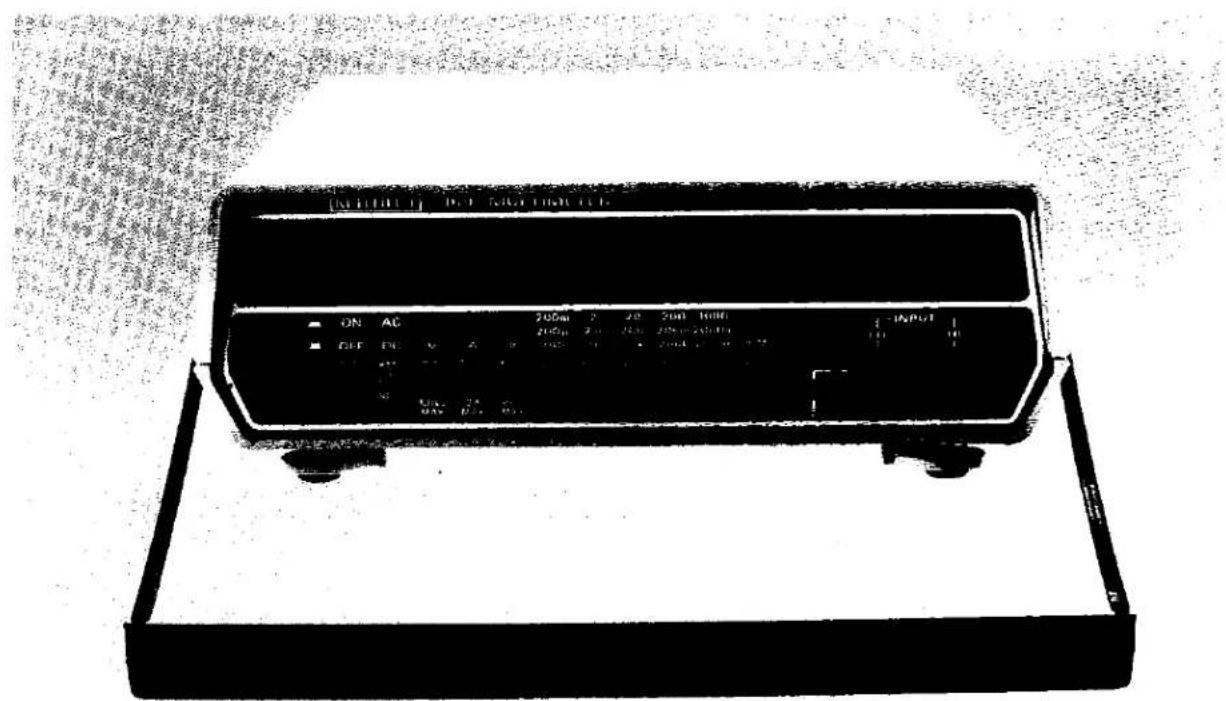
text_image
ON AC 200u 2 20 200 1000 240u 20 25u 25u-200u ON AC 200u 200u 200u INPUT ON AC 200u 25u 25uFIGURE 1-1. Model 169.
The latest LSI technology and stable precision components have been used in the Model 169 to provide long term accuracy and minimize maintenance. Only one calibration adjustment is required, once a year. If alkaline batteries are used, battery life can be the same as the calibration cycle. Barring destructive misuse, an MTBF of up to 20,000 hours can be expected.
● Automatic zeroing, automatic polarity and only two input terminals simplify operation by eliminating potentiometer zeroing and lead changing.
- Optional accessories can be ordered to extend the measurement capability of your Model 169. Some of these are:
High Voltage Probe allows your DMM to measure from 1000V to 40kV dc.
High Frequency (RF) Probe allows your DMM to measure from 0.25V to 30V rms ac over a frequency range of 100kHz to 100MHz.
Clamp-On AC Current Probe allows your DMM to measure from zero to 200A rms ac.
50-Ampere Current Shunt allows your DMM to measure from zero to 50A, ac and dc.
NOTE
Refer to Section 4 for more detailed information on accessories.
1-5. WARRANTY INFORMATION.
1-6. The warranty is given on the inside front cover of this Instruction Manual. If there is a need to exercise the warranty, contact the Keithley Representative in your area to determine the proper action to be taken. Keithley maintains service facilities in the United Kingdom and West Germany, as well as in the United States. Check the inside front cover of this manual for addresses.
1-7. CHANGE NOTICES.
1-8. Improvements or changes to the instrument which occur after printing of the Instruction Manual will be explained on a Change Notice sheet attached to the inside back cover.
1-9. SAFETY SYMBOLS.
1-10. Safety symbols used in this manual are as follows:
IMPORTANT
The symbol can be found in various places in this manual. Carefully read the associated CAUTION statements with regard to proper use and handling of the instrument. Damage to the instrument may occur if these precautions are ignored.

This symbol can be found in various places in this manual. This symbol indicates those areas on the instrument which are potential shock hazards. Carefully read the associated WARNING statements with regard to proper use and handling of the instrument. Serious personal injury may result if these precautions are ignored.
1-11. SPECIFICATIONS.
1-12. Detailed specifications for the Model 169 are given in Table 1-1.
TABLE 1-1.
Specifications
Model 169
DC VOLTAGE
| RANGE | RESOLUTION | ACCURACY (1 YEAR)18 - 28 °C |
| 200mV | 100μV | |
| 2 V | 1mV | |
| 20 V | 10mV | ±(0.25% of reading + 1 digit) |
| 200 V | 100mV | |
| 1000 V | 1 V |
MAXIMUM ALLOWABLE INPUT: 1000VDC, 1400V peak AC INPUT RESISTANCE: 10MΩ.
NORMAL MODE REJECTION RATIO: Greater than 50dB at 50Hz, 60Hz.
COMMON MODE REJECTION RATIO: Greater than 100dB at DC, 50Hz and 60Hz (1kΩ unbalance, 500V).
AC VOLTAGE
| RANGE | RESOLUTION | ACCURACY (1 YEAR) | |
| 45Hz - 1kHz | 1kHz-5kHz | ||
| 200mV | 100μV | ||
| 2 V | 1mV | ||
| 20 V | 10mV | ±(1% rdg + 5d) | ±(6% rdg + 7d) |
| 200 V | 100mV | ||
| 1000 V | 1 V | ||
MAXIMUM ALLOWABLE INPUT: 1000V rms, 1400V peak, 10°V·Hz, continuous except 200mV range: 350V continuous, 15 sec. maximum above 350V.
INPUT IMPEDANCE: 10MΩ shunted by less than 100pF.
RESPONSE: Average responding, calibrated in rms of a sinewave.
DC CURRENT
| RANGE | RESOLUTION | ACCURACY(1 YEAR)18°-28°C | MAXIMUM VOLTAGE BURDEN |
| 200μA | 100nA | 0.25V | |
| 2mA | 1μA | 0.25V | |
| 20mA | 10μA | ±(0.75% rdg + 1d) | 0.25V |
| 200mA | 100μA | 0.3 V | |
| 2000mA | 1mA | 0.7 V |
OVERLOAD PROTECTION: 2A fuse (250V), externally accessible.
AC CURRENT
| RANGE | RESOLUTION | ACCURACY(1 YEAR)18°-28°C(45Hz-1kHz) | MAXIMUM VOLTAGE BURDEN |
| 200μA | 100nA | 0.25V rms | |
| 2mA | 1μA | 0.25V rms | |
| 20mA | 10μA | ±(1.5% rdg + 5d) | 0.25V rms |
| 200mA | 100μA | 0.3 V rms | |
| 2000mA | 1mA | 0.7 V rms |
OVERLOAD PROTECTION: 2A fuse (250V), externally accessible.
RESISTANCE
| RANGE | RESOLUTION | ACCURACY(1 YEAR) | FULL SCALEVOLTAGE | |
| 18 | 28 °C | |||
| 200 Ω | 100mΩ | +10.3% rdg + 1dΩ | < 0.5V | |
| 2k Ω | 1 Ω | +10.2% rdg + 1dΩ | < 0.5V | |
| 20k Ω | 10 Ω | +10.2% rdg + 1dΩ | >0.7V | |
| 200k Ω | 100 Ω | +10.2% rdg + 1dΩ | >0.7V | |
| 2000k Ω | 1k Ω | +10.2% rdg + 1dΩ | >0.7V | |
| 20MΩ | 10k Ω | +12.0% rdg + 1dΩ | >0.7V | |
MAXIMUM OPEN CIRCUIT VOLTAGE: 1.5V except 2000 range 3.5V
MAXIMUM ALLOWABLE INPUT: 300V DC or rms
GENERAL
DISPLAY: 3 ^1 z-digit LCD. 0.6" numeral height with polarity range and function indicators.
OVERRANGE INDICATION: 3 least significant digits blanked
MAXIMUM COMMON MODE VOLTAGE: 1400V peak
OPERATING ENVIRONMENT: 0 to 50 C, less than 80% RH up to 35 C, less than 70% RH from 35 to 50 C.
STORAGE ENVIRONMENT: -35 to 60 C
TEMPERATURE COEFFICIENT 10 - 18 C and 28 -50 C: Less than 0.1 × applicable accuracy specification, per C
POWER: Six 1.5V "C" cells
BATTERY LIFE: 1000 hours typical with carbon zinc cells: 2000 hours with alkaline cells.
BATTERY INDICATOR: Display indicates "BAT" when less than 5% of life remains.
DIMENSIONS, WEIGHT: 85mm high × 235mm wide × 275mm deep (3 ^1/2 ″ × 9 ^1/4 ″ × 10 ^3/4 ″). Net weight 1.4kg (3 lbs.)
ACCESSORIES AVAILABLE:
1691 General Purpose Test Lead Set
1699 Spare Parts Kit to Maintain 10 169's for 1 Year
1600 High Voltage Probe
1651 50-Ampere Sh
1681 Clip-On Test Lead Set
1682 RF Probe
1683 Universal Test Lead Kit
1684 Hard Shell Carrying Case
1685 Clamp-On Current Probe
text_image
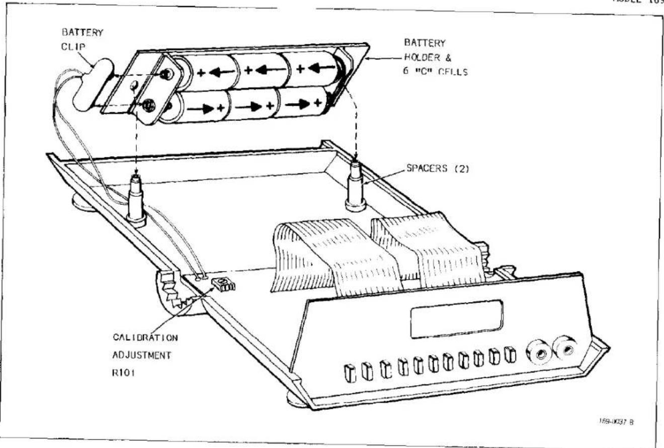
BATTERY CLIP BATTERY HOLDER & 6 "C" CFLLS SPACERS (2) CALIDRATION ADJUSTMENT R101 159-UK37 BFIGURE 2-1. Installation of Batteries.
text_image
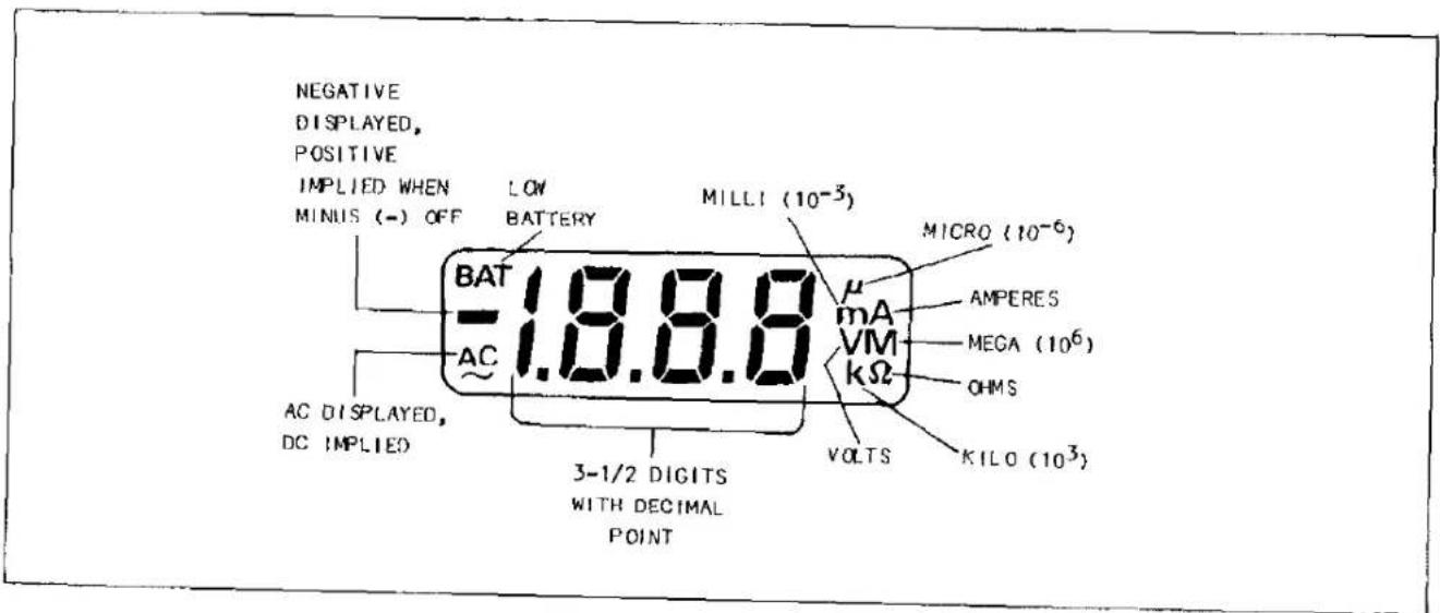
NEGATIVE DISPLAYED, POSITIVE IMPLIED WHEN MINUS (-) OFF LOW BATTERY MILLI (10⁻³) BAT AC AC DISPLAYED, DC IMPLIED 1.8.8.8 3-1/2 DIGITS WITH DECIMAL POINT μ mA VM kΩ VOLTS MICRO (10⁻⁶) AMPERES MEGA (10⁶) OHMS KILO (10³)FIGURE 2-2. Model 169 Front Panel Display.
2-2. This section provides information needed for incoming inspection, preparation for use and operation of the Model 169 and its accessories.
2-3. UNPACKING AND INSPECTION.
2-4. The Model 169 was carefully inspected, both mechanically and electrically before shipment. Upon receiving the Model 169, unpack all items from the shipping container and check for any obvious damage which may have occurred during transit. Report any damages to the shipping agent. Retain and use the original packaging materials if reshipment is required. The following items are shipped with all Model 169 orders:
a. Model :69 DMM
b. Six carbon zinc "C" cells (may be shipped installed in the DMM in some units).
c. A copy of this Manual.
d. Separate optional accessories, as ordered.
2-5. PREPARATION FOR USE.
2-6. Installation of Batteries, if required.
To prevent a shock hazard, all test leads should be removed from the INPUT terminals before removing the instrument top cover.
a. Turn the DMM bottom side-up and loosen the four screws in the bottom cover until the threads are not engaged. NOTE: The screws are not retained and they will fall out when the instrument is returned to its normal position.
b. Hold the top and bottom cover together to prevent their separation and turn the DMM cover to normal position. Lift off the top cover.
NOTE
Carbon-zinc batteries are supplied. These batteries will operate your DMM for approximately 1000 hours. If it is desired to change batteries only once a year when calibration is required, alkaline cells may be substituted. These cells will provide approximately 2000 hours of operation. In either case, the low battery indicator will automatically come on with approximately 5% of battery life remaining (20 hours for carbon-zinc and 40 hours for alkaline cells).
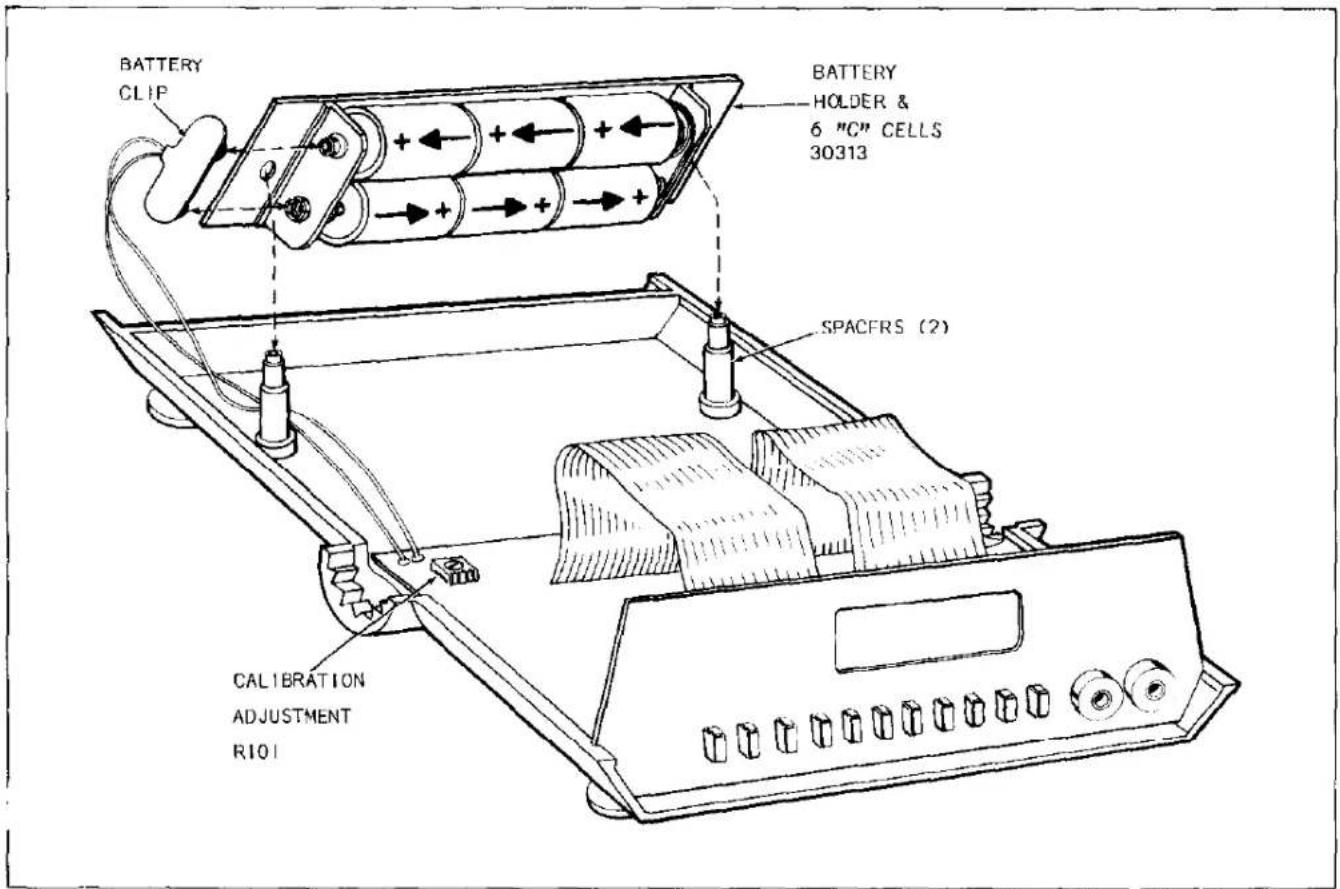
c. Install the batteries in the holder as shown in Figure 2-1.
d. Press the battery clip onto the terminals of the battery holder; then position battery holder on the two spacers as illustrated.
e. Reinstall the top cover.
f. After the batteries are installed, you should become familiar with the Model 169 by reading the section titled Controls, Indicators and Connectors (Paragraph 2-7); then perform the Initial Functional Check (Paragraph 2-16).
2-7. CONTROLS, INDICATORS AND CONNECTORS.
2-8. Display.
2-9. The operating status of the Model 169 is continuously provided by the 3-1/2 digit (2000 count) liquid crystal display located on the front panel. In addition to the digitized input signal, with appropriate decimal point and polarity, the display provides indications of the selected function and range, battery condition and overrange. All indicators on the display are shown in Figure 2-2 and described as follows.
a. Numerals. Large 0.6" numerals display up to a maximum of 1999 counts. Leading zero is only suppressed for most significant (1/2) digit.
b. Decimal Point. The decimal point is indicated in three positions and implied when behind the least significant digit. The decimal point is properly positioned when a range pushbutton is pressed.
c. Overrange. A "1" followed by three blanked digits is displayed as an overrange indication for all ranges and functions, except the 1000 volt ranges which read beyond their maximum allowable input voltages. The minus sign and a decimal point may also be displayed, if appropriate.
d. Polarity. For dc measurements the minus sign (-) is displayed, positive is implied. The minus sign may flash on any function at zero since it is not suppressed. It is also normal for it to flash in ohms while the instrument is recovering from overrange.
e. Low Battery Indication. BAT is displayed when approximately 5% of battery life remains. This indicates that the batteries should be replaced, however the Model 169 will continue to operate properly for 40 hours if alkaline cells are installed, or 20 hours if carbon-zinc cells are installed.
f. Function and Range Annunciators. These indicators provide a continuous display of the selected function and range, and allow direct reading of the display. For example: a displayed half-scale ac current on the highest current range would read AC 1000mA.
NOTE
Extended exposure of the liquid crystal display to direct sunlight, or high temperature and high humidity conditions can cause the display to temporarily blacken. Also, the display may become sluggish if exposed to extremely cold temperatures. Even though recovery occurs at normal operating temperatures, these conditions should be avoided for maximum display life.
2-10. Front Panel Switches.
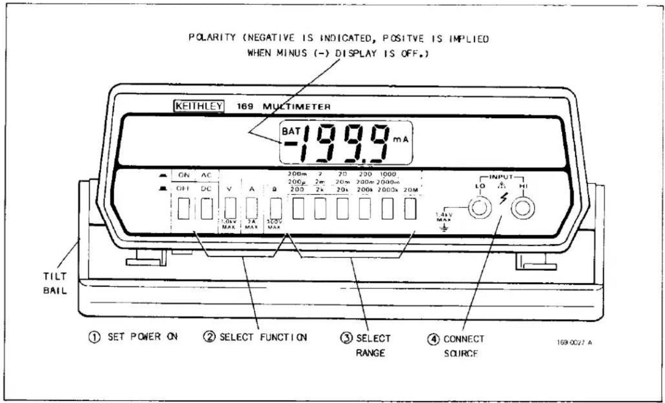
2-11. Control of the Model 169 is provided by eleven pushbutton switches which are color coordinated to the front panel. These switches are shown in Figure 2-3 and described as follows.
a. ON/OFF Pushbutton. Push on - push off switch that, when in, applies power to the DMM.
b. Function Pushbuttons. The four function push-buttons provide selection of the five functions of the Model 169. AC/DC is a push on - push off switch that selects whether the function is ac or dc, in for ac or out for dc. When ac is selected, the AC annunciator is on. When the annunciator is off, dc is implied. The AC/DC pushbutton is not effective when ohms (Ω) is selected. The V、A and Ω pushbuttons are push-on switches that select volts, amperes and ohms, respectively. Pressing one of these pushbuttons all the way in selects the new function, turns on the proper annunciator and cancels the previously selected function. Note that it is possible, by forcing, to push two pushbuttons in at the same time. This will be evidenced by conflicting range/function annunciators appearing, and the unwanted function can be canceled by pressing the desired function pushbutton again.
c. Range Pushbuttons. The six range pushbuttons are push-on switches which select the new range and cancel the previous one. The decimal point is positioned and the appropriate annunciator is turned on when the range is selected. The 20M pushbutton is only used for ohms function. If it is inadvertently selected with volts or current, contradicting annunciators will appear.
2-12. Input Connections.
2-13. Two banana jacks provide the input connections to the Model 169. The HI (red) jack is the high impedance input and is normally connected to the point in the test circuit most removed from signal or earth ground. The LO (black) jack is the common or low input.
TABLE 2-1 Initial Function Check
| STEP | SELECTION FUNCTION | RANGE | DMM INPUT | DISPLAY READING | REMARKS |
| 1 | Open | 000 | Power on, all other switches out. (-) may flash. | ||
| 2 | ACV | 200mV | Shorted | 00.0 ACmV | |
| 3 | DCV | 200mV | Shorted | 00.0 mV | |
| 4 | A and Ω* | 2k | Open | .100 mAΩ | Display reads 2mA current shunt on 2kΩ range. Checks current fuse. |
| 5 | A and Ω* | 200Ω and 2mA | Open | 1.00.0 μAΩ | Display reads 2mA current shunt on 200Ω range. (approx. 100Ω) |
| 6 | A and Ω* | 200Ω and 20mA | Open | 1.0.0 μAΩ | Display reads 20mA current shunt on 200Ω range. (10Ω) |
| 7 | Ω | 20M | Shorted | 0.00 MΩ | |
| 8 | Ω | 2000k | Shorted | 000 kΩ | |
| 9 | Ω | 2000k | Open | 1 kΩ | Overrange indication, leading 1 with all other digits blanked. |
| *Press both pushbuttons simultaneously. | |||||
text_image
POLARITY (NEGATIVE IS INDICATED, POSITIVE IS IMPLIED WHEN MINUS (-) DISPLAY IS OFF.) KEITHLEY 169 MULTIMETER BAT -19.9 mA ON AC 200m 2 20 200 1000 OFF DC V A Q 200μ 2m 20m 200m 2000m 1.4kV MAX INPUT LO HI TILT BAIL 1.4kV MAX ① SET POWER ON ② SELECT FUNCTION ③ SELECT RANGE ④ CONNECT SOURCE 169-0027 AFIGURE 2-3. Operating Controls.
To avoid electrical shock and/or instrument damage, do not connect the LO input to any source of more than 1400 volts (peak) above earth ground.
2-14. Tilt Bail/Handle.
2-15. The 16 position tilt bail/handle allows you to position the instrument for the best viewing angle of the display.
2-16. INITIAL FUNCTIONAL CHECK.
2-17. Now that the batteries are installed and you have become familiar with your DMM, the initial checkout procedure given in Table 2-1 should be performed. This procedure provides a quick and easy functional check of the DMM. Only test leads are required. The check is designed to cause all annunciators to appear, except for low battery (BAT). All decimal point locations are checked. All digit segments are checked, except for the horizontal center segment on the last three digits. Since the minus sign (-) is not suppressed on any function, it should periodically flash on one or more of the functions at zero with the input shorted. By selecting two functions and/or ranges in the test, the current fuse is checked and a rough indication of the condition of the respective current shunt and range resistor is obtained. However, this test is not intended to check the DMM accuracy, and thus, the indicated readings in the table are nominal with ±5 digits allowed. If it is desired to check the DMM accuracy specifications, perform the Performance Verification, Section 3. The Initial Functional Check is begun with power on and all other pushbuttons out. To obtain this condition it may be necessary to press unselected function and range pushbuttons slightly to cancel previous selections. After completing the functional check, operate the Model 169 in accordance with the Operating Instructions beginning with Paragraph 2-18.
2-18. OPERATING INSTRUCTIONS.
2-19. The basic operating instructions for the Model 169 DMM are outlined below. In addition, there are individual instructions provided in this section which describe how to make specific function measurements. Refer to Figure 2-3 and operate the DMM as follows.
Do not exceed the maximum input limits given in Table 2-2.
a. Turn on power by depressing the ON/OFF push-button. If the instrument is within 18-28°C, it is useable immediately to rated accuracy. If the ambient temperature is within 18-28°C range, but the DMM has been subjected to temperature extremes, up to 1 hour may be required to obtain rated accuracy.
b. Select the function with the AC/DC, V, A or Ω pushbuttons.
c. Select the range by depressing the appropriate range pushbutton.
d. Connect the source to the INPUT jacks and make the measurement. Accessories described in Section 4 should be used as required.
TABLE 2-2 Summary of Maximum Inputs
| FUNCTION | RANGE | MAXIMUM INPUT |
| DCV | ALL | 1000V DC, 1400V Peak AC |
| ACV | 200mV | 350V rms continuous, 15 sec. maximum above 350V |
| 2V-1000V | 1000V rms, 1400 peak, 10^6 V·Hz | |
| ACA, DCA | ALL | 2A, 250V DC or rms (fuse protected) |
| ALL | 300V DC or rms |
2-20. DC VOLTAGE MEASUREMENT.
2-21. The Model 169 reads dc voltage from 100 V /digit to 1000 volts. The maximum displayed reading is 1999 with appropriate decimal point. Polarity is automatically sensed and the minus sign (-) will be displayed, if applicable. Overrange is indicated by a "1" and three blanked digits, except on the 1000V range. On the 1000V range, the display can read beyond the maximum allowable input voltage. Maximum allowable input: 1000V dc, 1400 peak ac. Use the Model 169 to measure dc voltage as follows:

CAUTION
Do not exceed the maximum allowable input voltage. Instrument damage may occur.
a. Turn on power with the ON/OFF pushbutton; select dc volts with the V and AC/DC pushbuttons. The "V" annunciator should appear.
b. Select the range from the five ranges available. The decimal point is positioned by the range pushbutton. The "m" annunciator will appear if 200mV range is selected.
c. Connect the signal to be measured between the INPUT HI and LO jacks; observe the voltage reading on the display.
2-22. AC VOLTAGE MEASUREMENT.
2-23. The Model 169 reads ac voltages from 100 V /digit to 1000 volts. The instrument is average responding, calibrated to read the root mean square value of a sine wave within a frequency of 45Hz to 5kHz. The maximum reading is 1999 with appropriate decimal point. Overrange is indicated by a "1" followed by three blanked digits, except on the 1000V range. On the 1000V range, the instrument can read beyond the maximum allowable input voltage. Maximum allowable input voltage: 1000V rms, 1400V peak, 10^6V · Hz maximum. Use the Model 169 to measure ac voltage as follows.

CAUTION
Do not exceed the maximum allowable input voltage. Instrument damage may occur.
a. Turn on power with the ON/OFF pushbutton; select ac volts with the V and AC/DC pushbuttons.
b. Select the range from the five ranges available. The decimal point is positioned by the range pushbuttons. The "m" annunciator will appear if 200mV range selected.
c. Connect the signal to be measured between the INPUT HI and LO jacks; observe the voltage reading on the display.
2-24. AC OR DC CURRENT MEASUREMENT.
2-25. The Model 169 reads ac and dc currents from 100nA/digit to 2000 milliamperes (2A). For ac measurements the instrument is average responding, calibrated to read the root mean square value of a sine wave of a frequency within 45Hz to 1kHz. The maximum reading is 1999, with appropriate decimal point. Overrange is indicated by a "1" followed by three blanked digits. Input overload protection is provided by 2A, 250V dc or rms, quick-blow fuse. Use the Model 169 to measure, ac or dc current as follows.

CAUTION
Do not install a larger capacity current fuse than the one originally supplied (2A, 250V). Instrument damage may occur.
a. Turn on power with the ON/OFF pushbutton. Select ac or dc with the AC/DC pushbutton; depress A pushbutton. The "A" annunciator should appear along with the "AC" annunciator if ac was selected.
b. Select the range from the five ranges available. The decimal point is positioned by the range pushbutton. The "μ" annunciator will appear if 200μA range was selected; otherwise, the "m" annunciator will appear. It should be noted that the voltage drop across the current shunt in the instrument (called voltage burden) can affect the circuit under test if it has a low source voltage. This voltage burden can be reduced by selecting the highest current range that will resolve the desired measurement.
c. Connect the signal to be measured to the INPUT HI and LO jacks; observe the current reading on the display.
2-26. RESISTANCE (Ω) MEASUREMENT.
2-27. The Model 169 reads resistance from 100mΩ/digit to 20 megohms. The maximum reading is 1999 with appropriate decimal point. Overrange is indicated by a "1" followed by three blanked digits. Maximum Allowable Input: 300V dc or rms. Use the Model 169 to measure resistance as follows.
CAUTION
Turn the test circuit off and discharge all capacitors before attempting in-circuit measurements. A voltage may be present in the circuit if either the minus sign is displayed, along with a steady displayed number other than zero, or the reading changes more than two digits when the leads are reversed.
a. Turn on power and depress the Ω pushbutton. The "Ω" annunciator should appear.
b. Connect the circuit to be measured to INPUT HI and LO and select the desired range from the six ranges available. The decimal point is positioned by the range pushbutton and the applicable range annunciator should appear.
c. Read the resistance on the display. If the 200Ω range is selected, disconnect the test leads at the test circuit, short them together and subtract the reading obtained from the reading obtained above.
NOTE
As previously mentioned for in-circuit measurements, the presence of a voltage will cause a change in the reading when the leads are reversed. The presence of a forward biased semiconductor junction will also cause a significant error, and therefore, it is a good practice to reverse the leads and make comparative measurements of in-circuit resistances. In addition, it should be noted that the bottom two resistance ranges will not turn on most semiconductors, except in an overrange condition.
d. Diode Tests. Any of the top four ohms ranges will turn on semiconductor junctions, with an on-scale reading, but the 20KΩ range is recommended for out-of-circuit tests of semiconductors because its test current is higher. To test a junction, first forward bias it and then reverse bias it while observing the display reading for both conditions. The HI jack is positive. Compare the results as follows:
| INDICATION | JUNCTION CONDITION |
| 1. Overrange, both Polarities | OPEN |
| 2. Low reading, both polarities | SHORTED |
| 3. Overrange when reverse biased and an on-range reading when forward biased | PROBABLY GOOD |
SECTION 3. PERFORMANCE VERIFICATION
3-1. GENERAL.
3-2. Performance verification may be performed upon receipt of the instrument to ensure that no damage or misadjustment has occurred during transit. Verification may also be performed whenever there is question of the instrument's accuracy, and following calibration, if desired.
NOTE
For instruments that are still under warranty (less than 12 months since date of shipment), contact your Keithley representative or the factory immediately if the instrument falls outside of specifications as determined by the Performance Verification Procedure in paragraph 3-7.
3-3. RECOMMENDED TEST EQUIPMENT.
3-4. Recommended test equipment for performance verification (and calibration) is listed in Table 3-1. Alternate test equipment may be used. However, if the accuracy of the alternate test equipment is not at least 10 times better than the instrument specifications, additional allowance must be made in the readings obtained.
3-5. ENVIRONMENTAL CONDITIONS.
3-6. All measurements should be made at an ambient temperature within the range of 18° to 28°C (65° to 82°F), and a relative humidity of less than 80%.
3-7. PERFORMANCE VERIFICATION PROCEDURE.
3-8. Use the following procedures to verify the basic accuracy of the Model 169 for voltage, resistance and current measurements.
TABLE 3-1 Recommended Test Equipment for Performance Verification.
| ITEM | DESCRIPTION | SPECIFICATIONS | MFR. | MODEL |
| A | DC Calibrator | 0.1V, 1V, 10V, 100V1000V, ±0.005% | Fluke | 341A |
| B | AC Calibrator | 0.1V, 1V, 10V, 100V±0.022% | H-P | 745A |
| C | AC Calibrator/Amplifier | 1000V ±0.04% | H-P | /45A//46A |
| D | Decade Resistor | 1.9kΩ, 19kΩ, 190kΩ,1.9MΩ, 10MΩ,±0.02% | ESI | DB62 |
| E | Current Calibrator | 100μA, 1mA, 10mA,100mA, 1A, ±0.03% | Valhalla | 2500 |
NOTE
Performance verification should be performed by qualified personnel using accurate and reliable test equipment.
3-9. Initial Conditions.
3-10. Before beginning the verification procedure the instrument must meet the following conditions:
a. If the instrument has been subjected to extremes of temperature, allow internal temperature to stabilize for one (1) hour minimum at the environmental conditions specified in paragraph 3-5.
b. Turn the instrument on and check for low battery indication. If low battery indicator (BAT) is on, remove and replace the batteries with fresh ones.

WARNING
Some procedures require the use of high voltage. Take care to prevent contact with live circuits which could cause electrical shock resulting in injury or death.
3-11. DC Volts Checkout.
a. Select dc voltage readings with the AC/DC and V pushbuttons.
b. Connect the DC Calibrator (Item A, Table 3-1) to the instrument.
c. Select the 200mV range, and apply positive 100mVdc to the DMM. The reading must be within the limits specified in Table 3-2.
d. Select each remaining range and apply the required voltage as specified in Table 3-2, verify that the reading is within specifications.
e. Repeat all checks with negative voltage.
TABLE 3-2
DC Voltage Performance Check
| Range | Applied Voltage | Allowable Reading at 18° to 28°C |
| 200mV | 100.00 mV | 99.6 to 100.4 |
| 2 V | 1.0000 V | .996 to 1.004 |
| 20 V | 10.000 V | 9.96 to 10.04 |
| 200 V | 100.00 V | 99.6 to 100.4 |
| 1000 V | 1000.0 V | 996 to 1004 |
3-12. AC Volts Checkout.
a. Select ac voltage readings with the AC/DC and V pushbuttons.
b. Connect the AC Calibrator (Item B, Table 3-1) to the DMM. Set the calibrator frequency to 1kHz.
c. Set the DMM to the 200 mV range and apply 100 mV ac to the OMM. The reading must be within the limits specified in Table 3-3.
d. Select the 2, 20 and 200 volt ranges and apply the required voltages as specified in Table 3-3. Verify that the readings are within specifications.
e. To check the 1000 volt range, connect the AC Calibrator Amplifier (Item C, Table 3-1) to the output of 1000 volts ac rms and verify that the DMM reading is within the specified limits.
TABLE 3-3
AC Voltage Performance Check
| Range | Applied Voltage | Allowable Reading at 18° to 28°C |
| 200mV | 100.00 mV | 98.7 to 101.3 mV |
| 2 V | 1.0000 V | .987 to 1.013 V |
| 20 V | 10.000 V | 9.87 to 10.13 V |
| 200 V | 100.00 V | 98.7 to 101.5 V |
| 1000 V | 1000.0 V | 987 to 1013 V |
3-13. Resistance Checkout.
a. Select resistance readings by pressing the a pushbutton.
b. Select the 200 Ω range.
c. Connect the decade resistor (Item D, Table 3-1) to the DMM.
d. Set the decade resistor to zero and measure the resistance of the test leads. Subtract this reading from the display in all of the following steps.
e. Set the decade resistance to 190.0. Verify that the reading is within the limits specified in Table 3-4.
f. Continue the resistance check by selecting the next range and measuring the next resistance as specified in Table 3-4. Verify that the reading is within specifications. Test each item in the table.
TABLE 3-4 Resistance Performance Check
| Range | Resistance | Allowable Reading at 18° to 28°C |
| 200 Ω | 190.0 Ω | 189.1 to 190.9 Ω |
| 2 kΩ | 1.900kΩ | 1.895 to 1.905 KΩ |
| 20 kΩ | 19.00kΩ | 18.95 to 19.05 KΩ |
| 200 kΩ | 190.0kΩ | 189.5 to 190.5 KΩ |
| 2000 KΩ | 1.900kΩ | 1895 to 1905 KΩ |
| 20 MΩ | 10.00MΩ | 9.79 to 10.21 MΩ |
3-14. DC Current Checkout.
a. Select dc current readings with the AC/DC and A pushbuttons.
b. Connect the dc current source (Item E, Table 3-1) to the DMM.
c. Select the 200μA range and apply a current of 100.00μA to the OMM. The reading must be within the limits in Table 3-5.
d. Select each range and apply the required current as specified in Table 3-5. Verify that the reading is within specifications.
3-15. ANALYSIS.
3-16. If the instrument is out of the specified limits given in Tables 3-2 through 3-5, either troubleshooting and repair or calibration, as described in Section 6, may be required. Normally, recalibration will only be the indicated solution when the instrument is out of specification on more than one function (except for the higher ranges of DC volts which are the most critical). If the instrument is still under warranty, refer to the Note in Paragraph 3-2.
TABLE 3-5 DC Current Performance Check
| Range | Applied Current | Allowable Reading at 18° to 28°C |
| 200 μA | 100.00 μA | 99.1 to 100.9 μA |
| 2 mA | 1.0000 mA | .991 to 1.009 mA |
| 20 mA | 10.000 mA | 9.91 to 10.09 mA |
| 200 mA | 100.00 mA | 99.1 to 100.9 mA |
| 1000 mA | 1000.0 mA | 991 to 1009 mA |
[Non-Text]
[Non-Text]
[Non-Text]
[Non-Text]
[Non-Text]
[Non-Text]
[Non-Text]
[Non-Text]
[Non-Text]
[Non-Text]
[Non-Text]
[Non-Text]
SECTION 4. ACCESSORIES
4-1. GENERAL.
4-2. This section describes the various accessories and options available for use with the Model 169 DMM.
4-3. MODEL 1600 HIGH VOLTAGE PROBE.
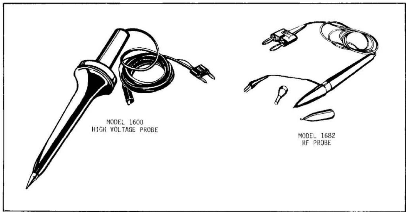
4-4. The Model 1600 High Voltage Probe (shown in Figure 4-1) extends the measurable dc voltage range up to 40 kilovolts. It has a 1000:1 division ratio, so that a reading of 1 volt on the DMM corresponds to 1 kilovolt (1000 volts). To use the probe, select DCV and the required range, connect the high voltage probe banana plug to the instrument, connect the alligator clip to source low, and touch the probe tip to source high.
Be sure the alligator clip is connected to source low before touching probe tip to source high. A shock hazard or damage to instrument may result.
Specifications
Voltage Range: 0 to 40,000 volts DC.
Input Resistance: 1000 megohms.
Division Ratio: 1000:1.
Ratio Accuracy:
±1.5% at 25kV, decreasing to
±2.0% at 20kV and 30kV,
±3.0% at 10kV and 40kV, and
±4.0% at 1kV.
Ratio Stability: ±0.01% per °C; ±0.1% per year.
Heating Effects: Self-heating due to application of high voltage for period in excess of 1 minute will cause a maximum of 0.2% additional error at 40kV (error is less at lower voltage).
4-5. MODEL 1651 50-AMPERE SHUNT
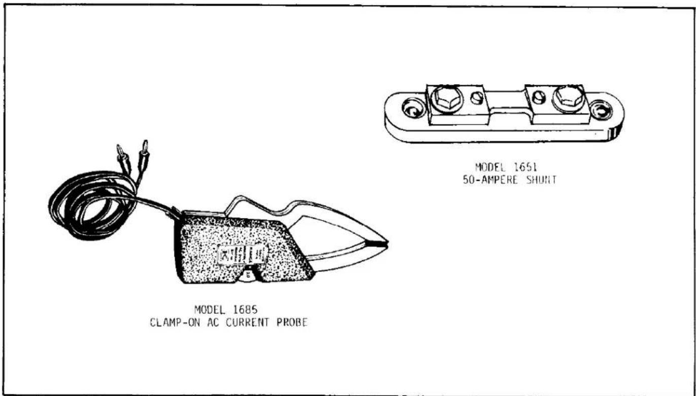
4-6. The Model 1651 50-Ampere Shunt (shown in Figure 4-2) permits current measurements of up to 50 amperes ac or dc. The shunt has a resistance of 0.001 ohm ±1%, so that a 50-ampere current will correspond to a reading of 50 millivolts (0.0500 volt). Set the DMM to ACV or DCV and select the required range. To use the shunt, connect the leads furnished with the shunt from the shunt screw terminals to the DMM input terminals. Use separate leads (not furnished) to connect the source to the hex head bolts. Be sure to use leads with a capacity of 50 amperes, or as needed.
4-7. MODEL 1681 CLIP-ON TEST LEAD SET
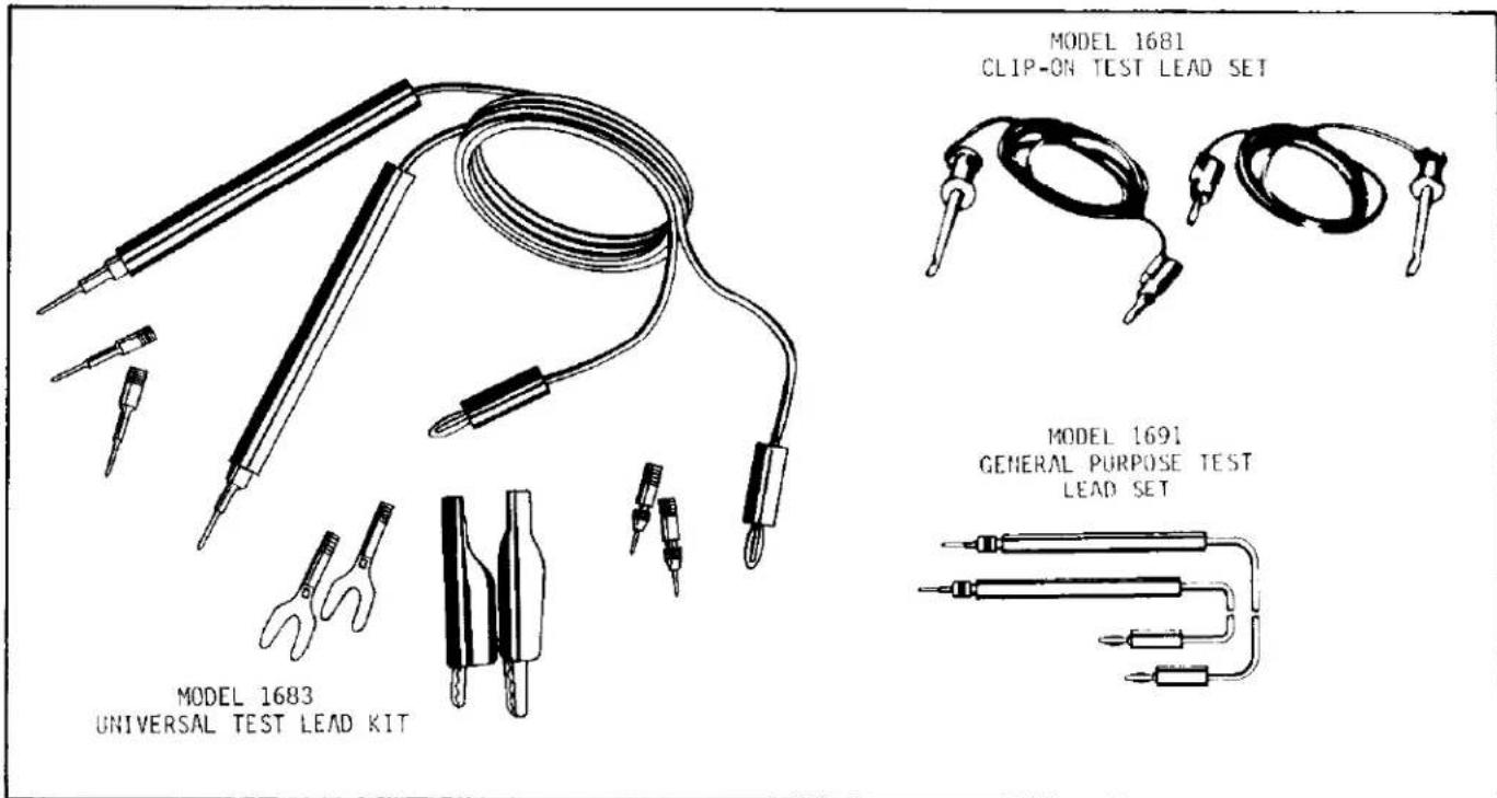
4-8. This set (shown in Figure 4-3) contains two leads with banana plugs at one end and spring-action clip-on probes at the other end. To use, insert the banana plugs into the DMM and attach the probes to the source.
4-9. MODEL 1682 RF PROBE
4-10. The Model 1682 RF Probe (shown in Figure 4-1) permits measurement of ac voltages at frequencies of 20 kilohertz to 100 megahertz. Connect the probe to the input terminals and select DCV and the appropriate range.
Specifications
Voltage Range: 0.25 to 30 volts rms.
Transfer Accuracy: ±0.5dB, 100kHz to 100MHz peak responding calibrated in rms of a sinewave.
Input Impedance: 4 megohm shunted by 3pF.
Maximum Allowable Input: 30V rms AC, 200V DC.
Accessories Supplied: straight-tip, hook tip, ground clip, hi adapter, banan plug adapter.
4-11. MODEL 1683 UNIVERSAL TEST LEAD KIT.
4-12. This kit (shown in Figure 4-3) contains two test leads and 12 screw-in adapter tips. The tips consist of two alligator tips with boots, two banana plugs, two needle tips with chucks, two spade lugs and four heavy duty tip plugs which permit connection of the DMM to virtually any source within its measurement range.
4-13. MODEL 1684 CARRYING CASE.
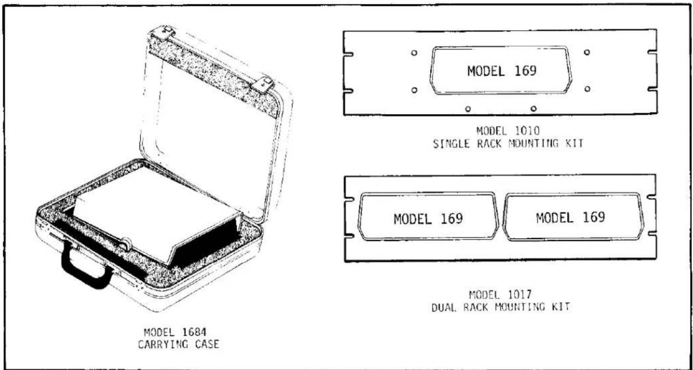
4-14. The Model 1684 Carrying Case (shown in Figure 4-4) is a hard vinyl case with a fitted foam insert to help protect the Model 169 from damage. There is also room in the case for the Instruction manual and small accessories
4-15. MODEL 1685 CLAMP-ON AC CURRENT PROBE.
4-16. The Model 1685 Clamp-On AC Current Probe (shown in Figure 4-2) permits measurement of ac current by clamping around a single conductor, eliminating the need to interrupt the current path. Plug the ac current probe into the DMM and select
ACV and the appropriate range. The DMM will display 0.1 volt rms per ampere.
4-17. MODEL 1691 GENERAL PURPOSE TEST LEAD SET.
4-18. The Model 1691 General Purpose Test Lead Set (shown in Figure 4-3) consists of two .91m (36 inches) test leads with probe tips terminated in banana plugs.
4-19. MODEL 1699 SPARE PARTS KIT.
4-20. The Model 1699 contains a complement of spare parts that will maintain up to 10 Model 169 DMMs for one year. The parts are listed in Table 7-1 of Section 7, Replaceable Parts.
4-21. MODELS 1010 and 1017 RACK MOUNTING KITS.
4-22. The rack mounting kits (shown in Figure 4-4) permit mounting one or two Model 169 DMMs in a 19-inch rack for convenient viewing.
text_image
MODEL 1600 HIGH VOLTAGE PROBE MODEL 1682 RF PROBEFIGURE 4-1. High Voltage Probe and RF Probe.
text_image
MODEL 1651 50-AMPERE SHUNT MODEL 1685 CLAMP-ON AC CURRENT PROBEFIGURE 4-2. Current Probe and Current Shunt.
text_image
MODEL 1681 CLIP-ON TEST LEAD SET MODEL 1691 GENERAL PURPOSE TEST LEAD SET MODEL 1683 UNIVERSAL TEST LEAD KITFIGURE 4-3. Convenience Cable and Connectors.
text_image
MODEL 169 MODEL 1010 SINGLE RACK MOUNTING KIT MODEL 169 MODEL 169 MODEL 1017 DUAL RACK MOUNTING KIT MODEL 1684 CARRYING CASEFIGURE 4-4. Carrying Case and Rack Mounting Kits.
SECTION 5. THEORY OF OPERATION
5-1. GENERAL.
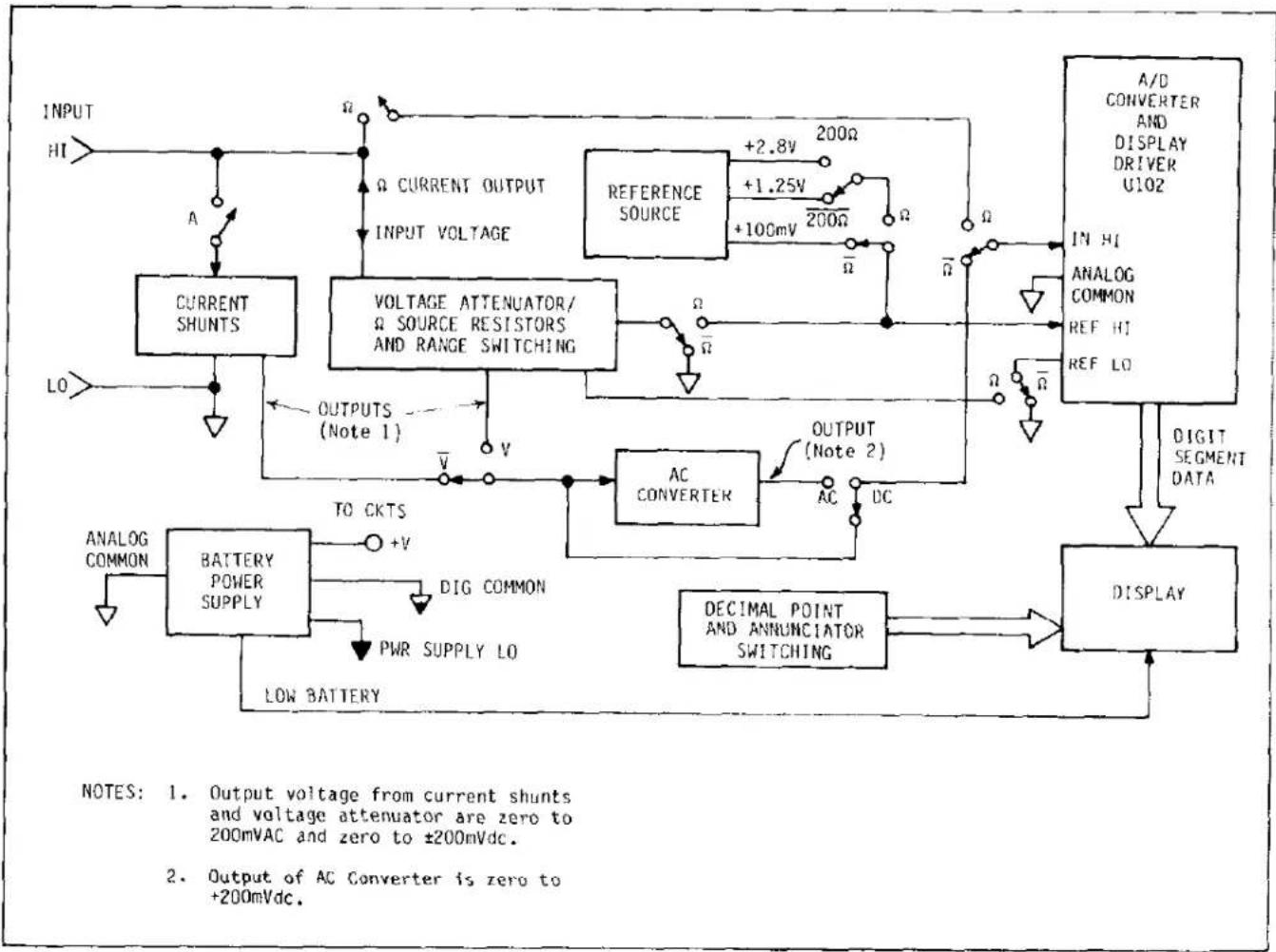
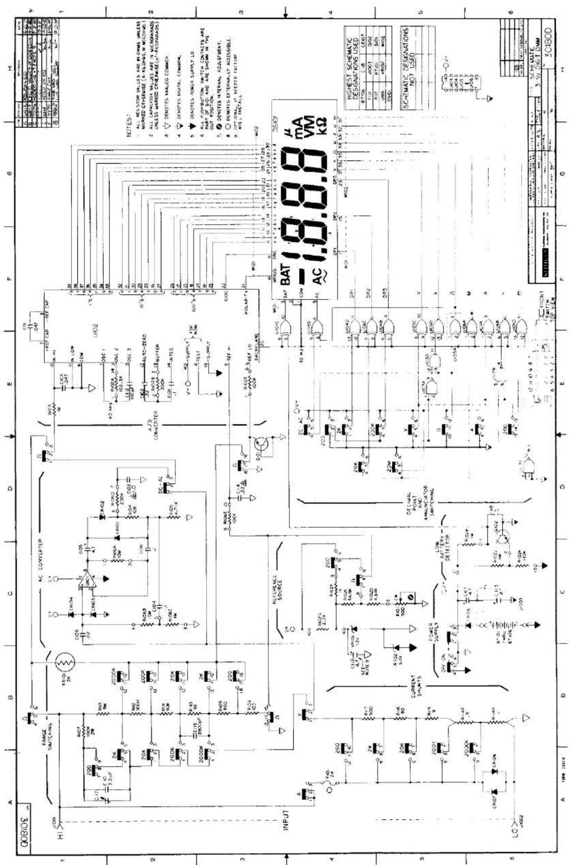
5.2. This section contains circuit descriptions for the Model 169 DMM. An overall block diagram of signal flow is provided in Figure 5-1. The overall schematic diagram, drawing 30180D, is contained in Section 7 of this manual.
5-3. OVERALL OPERATION.
5-4. As shown in Figure 5-1, the heart of the Model 169 is a single chip A/D converter with built-in liquid crystal display drivers. The displayed reading is the ratio of two floating input voltages to this converter. On all functions except ohms, one voltage (Reference) is 100mV. The other voltage ( V_INHI ) is the unknown input current or voltage to the Model 169 which is converted and/or scaled by the input signal conditioning circuitry to a dc voltage between zero and ±200mV. The displayed reading is then determined by the formula: 1000 ( V_INHI + V_REFERENCE ). The A/D converter also automatically determines the polarity of the input signal and detects whether an overrange condition exists (>1999 counts). A minus sign is displayed, plus is implied, and an overrange is displayed by a l with the last three digits blanked. The annunciators are displayed by the combination of range and function switching, and the decimal point is positioned by the range switching.
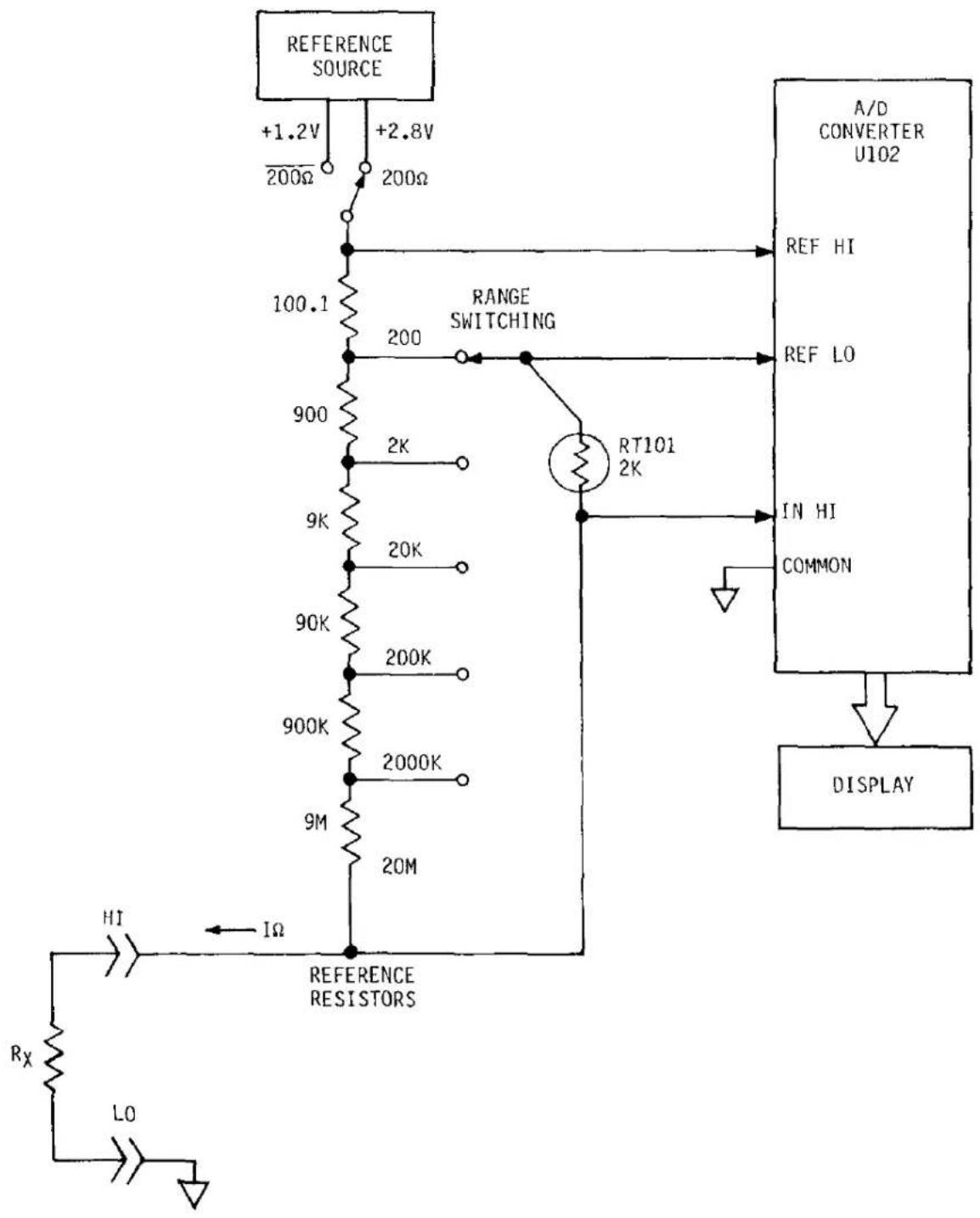
5-5. For the ohms function, a reference resistor is placed in series with the unknown resistor and a voltage is applied. Since the same current flows through both resistors, the ratio of their voltages is the same as the ratio of their resistances. Thus, the voltage across each resistor is measured by the A/D converter and their ratio is displayed per the formula: 1000 (VR X + VR REFERENCE ).
5-6. SIGNAL CONDITIONING.
5-7. AC/DC Voltage Measurements.
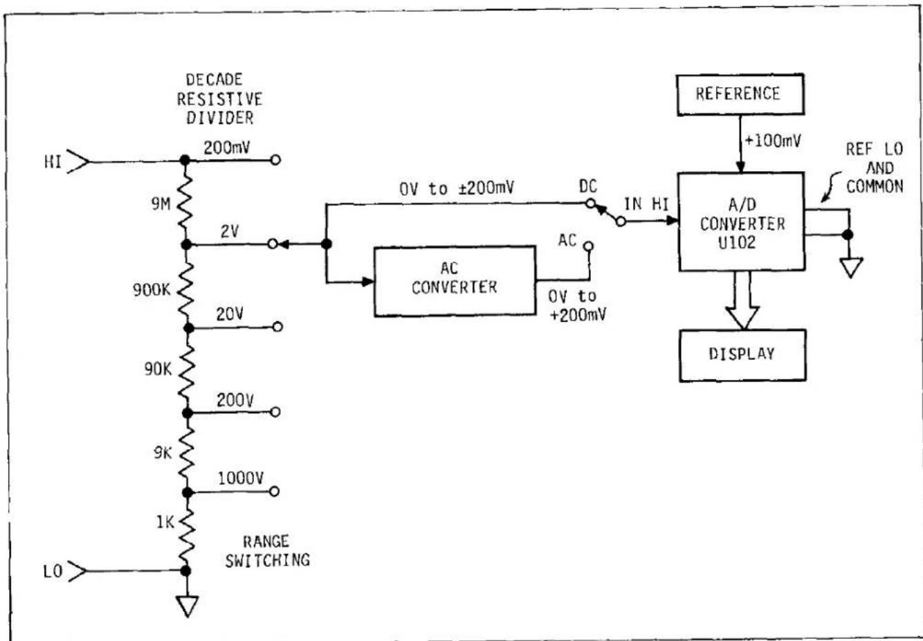
5-8. For voltage measurements, as shown in Figure 5-2, the input is divided by 1, 10, 100, 1000, or 10,000 by the 10 megohm resistive divider. The resulting output from the divider is a 0 to 200mV voltage. For a dc input, this voltage is applied direct to the A/D converter along with the 100mV reference. It should be noted that, since no active gain or attenuator stages are used, the dc accuracy is determined primarily by the precision resistor accuracies (actually their ratios) and the reference adjustment.
5-9. For an ac input, the output of the resistive divider is first applied to the AC Converter. The AC converter is a half wave rectifier with 100μV resolution and sufficient gain to provide a positive dc output voltage equivalent to the rms value of a sinusoidal input. Thus, for sinusoidal input of 100mVac, the output will be 100mVdc. The important gain determining elements of the converter are precision resistors so that a gain adjustment is not required.
5-10. AC/DC Current Measurement.
5-11. For current measurements, as shown in Figure 5-3, the appropriate shunt resistor is placed across the DMM input in accordance with the selected range. As with voltage measurements, the voltage drop across the current shunt is designed to be 200mV for a full scale input current on any range. Therefore, after the input current is converted to a voltage, the measurement process for current is identical to that for voltage measurements. Accuracy for dc current measurements is primarily determined by the accuracies of the precision shunt resistors and the reference adjustment. These two items also affect ac accuracy along with any error contributed by the AC Converter.
5-12. Resistance Measurements.
5-13. Resistance measurements are made by comparing the voltage drop across the unknown resistance to the voltage drop of an internal reference resistor as shown in Figure 5-4. For this ratio measurement technique, a voltage is connected to the input divider used for voltage measurements and the range switching selects a 1/2 of full scale value reference resistance to be placed in series with the unknown resistor. The voltage drops are then compared by the A/D converter and displayed on the LCD. A 2 kilohm thermistor (RT101) provides overvoltage input protection for the low resistance ranges and it is in series with the reference resistor and the unknown resistor on all but the 20 megohm range. For this reason, the +V (+2.8V nominal) top of the reference is selected on the 200 ohm range. On all other ranges +1.2V is used. Since a ratio technique is used, actual values of the reference resistors determine the primary accuracy for resistance measurements, and no adjustments are necessary.
5-14. A/D CONVERTER.
5-15. As shown in Schematic 30180D, the A/D converter and display drivers are contained on a single integrated circuit (U102). This chip also contains an oscillator and the regulators that are used to establish the analog and digital grounds. External components are used to establish the timing and reference levels required for A/D operation. U102 employs the dual slope principle of A/D conversion. This method provides a measurement cycle consisting of three consecutive time periods, autozero, signal integrate and reference integrate (read). Timing for these periods, and thus the measurement period, is a function of the oscillator frequency. The oscillator components are selected to provide 40 kHz which results in a 100 millisecond signal integrate period for best rejection of 50Hz and 60Hz. To begin each measurement cycle, the autozero period is set to a minimum of 100 milliseconds. During this period, the reference voltage input to the A/D is
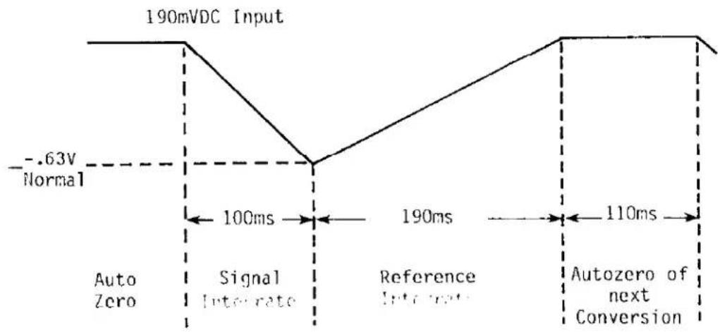
stored on capacitor C111 and the A/D converter is referenced to analog common. A correction voltage is then stored on capacitor C102 for use during the remainder of the measurement cycle, if any amplifier offset exists. The second phase of the measurement cycle is the 100mS signal integration period as previously mentioned. During this period, the differential voltage between IN HI and IN LO is integrated. At the end of this period, the polarity of the integrated signal is also determined. The final phase is reference integrate, or read. During this period, internal circuitry ensures that the reference capacitor will be connected with the correct polarity to return the integrator output to the autozero level. The time required for the output to return to this level is proportional to the unknown input signal. The read period can be from zero to 200 milliseconds, corresponding to displayed counts of zero to 2000 full scale as determined by 1000 ( V_IN + V_REF ). For input signals less than full scale, the A/D converter reverts to autozero for the remainder of the reference integrate period. Thus, a complete measurement cycle is 400ms, which results in a display update rate of 2-1/2 per second.
5-16. DISPLAY CIRCUITS.
5-17. The liquid crystal display (LCD) and its associated circuitry is shown in Schematic 30180D. As previously mentioned, the seven segment decoders and drivers are provided by the A/D converter chip U102. The digitized measurement data is presented on the output lines to the LCD. These lines are driven by a square wave having the same amplitude and frequency as the BACKPLANE line (nominally 0 to +5V at 50Hz). When the lines to the display segments are driven out of phase with BACKPLANE the segments are ON. Conversely, when in-phase the segments are OFF. The annunciators and decimal points are turned ON and OFF similarly, with the phasing of their lines controlled by the range and function switches through logic gates. A summary of annunciator switching is given in Table 5-1.
5-18. REFERENCE SOURCE.
5-19. The reference source supplies 100mV (regulated and calibrated) to the A/D converter for voltage and current measurements. It also provides approximately 2.8V to the 200Ω range and approximately 1.2V to all other Ω ranges during resistance measurements. The heart of the reference source is a band-gap reference (VR101) that regulates the voltage to a value between 1.20 and 1.25 volts at approximately 500μA. Recall that the voltage applied to the reference source depends on the internal regulator in the A/D converter which establishes analog ground nominally 2.8 volts below V+. Thus, the value of R102G is selected to provide a minimum current of 400μA to VR101 to ensure a good temperature coefficient. R101 provides the calibration adjustment, while R102D and R102E limit the adjustment span and are stable precision resistors to ensure the 1 year calibration cycle.
5-20. LOW BATTERY DETECTOR.
5-21. The low battery detector is a simple transistor switch (Q102) which compares the negative supply to digital common (ground). Q102 is set for a nominal supply voltage of 6.9 volts. (Actual battery voltage will be about 7.2 volts due to the drop of CR105.) In the Model 169, the primary limit to battery usefulness is the integrator swing on the high ohms ranges with a full scale input. For this reason, the low battery indicator (BAT) should turn on with a battery voltage of 6.5 volts, or above, for the proper functioning of the A/D Converter and the low battery indicator.
5-22. INPUT PROTECTION.
5-23. Effective input protection circuitry has been designed into the Model 169 which provides protection against accidental input overloads on all functions and ranges. This circuitry is described in the following paragraphs for each function.
5-24. Voltage Protection.
5-25. R107 and R103 protect the A/D converter during dc voltage measurements by limiting the current to ±1mA.
5-26. For ac voltage measurements, U101 is protected by using R107 for current limiting and CR103 and CR104 to clamp the voltage to digital common and V+. Overload currents are returned to analog common through C107, C113 and the A/D converter.
5-27. Current Protection.
5-28. On the higher current ranges, F101 (2A, 250V) opens for input current overloads with up to 250 volts. On the lower current ranges, CR106 and CR107 clamp the input voltage to about 1 volt until F101 opens.
5-29. Ohms Protection.
5-30. Transistor Q101 and thermistor RT101 are the basic components used to provide protection during resistance measurements. Q101 is used as a low leakage zener to clamp any unintentionally applied voltage to ground. RT101 is a positive temperature coefficient thermistor which bears the applied voltage by increasing its resistance. This limits current to protect Q101. R103 is used to protect IN HI of the A/D converter as in OC volts. Since the voltage across Q101 can be 10 volts above the positive supply, R102C protects REF LO and R106E protects REF HI by limiting the current to +100μA. Since VR101 has a current limit of 10mA, it is protected by R102G on the 200Ω range and by R102F plus the divider resistance on the other ranges. For negative input overloads the circuit operates the same, except Q101 is then forward biased and clamps to ANALOG COMMON.
TABLE 5-1 Annunciator Truth Table
| ANNUNCIATOR | SWITCH | CONDITION |
| BAT | Q102 | OFF |
| AC | DC/ACΩ | ACOFF |
| DP1 | 2K | ON |
| DP2 | 20K or 20M | ON |
| DP3 | 200 or 200K | ON |
| V | V | ON |
| Ω | Ω | ON |
| k | 200 and 20MΩ | OFFON |
| M | 20M | ON |
| A | A | ON |
| μ | A and 200 | ON |
| m | 1. A200 | ONOFF |
| 2. V and 200 | ON |
flowchart
graph TD
    A["INPUT HI"] --> B["A CURRENT SHUNTS"]
    B --> C["VOLTAGE ATTENUATOR/Ω SOURCE RESISTORS AND RANGE SWITCHING"]
    C --> D["REFERENCE SOURCE"]
    D --> E["+2.8V 200Ω +1.25V +100mV 200Ω"]
    E --> F["IN HI ANALOG COMMON REF HI REF LO"]
    F --> G["DIGIT SEGMENT DATA"]
    G --> H["DISPLAY"]
    H --> I["DECIMAL POINT AND ANNUNCIATOR SWITCHING"]
    I --> J["LOGIC REGISTRATOR"]
    J --> K["AC CONVERTER"]
    K --> L["OUTPUT (Note 2)"]
    L --> M["LOGIC REGISTRATOR"]
    M --> N["LOGIC SECTOR"]
    N --> O["Digital Display"]
    P["ANALOG COMMON"] --> Q["BATTERY POWER SUPPLY"]
    Q --> R["TO CKTS +V"]
    R --> S["DIG COMMON"]
    S --> T["PWR SUPPLY LO"]
    T --> U["LOW BATTERY"]
    V["OUTPUTS (Note 1)"] --> W["VGND"]
    X["LOGI"] --> Y["LO"]
    Z["LOGI"] --> AA["LO"]
    AB["A/D CONVERTER AND DISPLAY DRIVER U102"] --> AC["IN HI ANALOG COMMON REF HI REF LO"]
    AD["LOGI"] --> AE["LOGI"]
FIGURE 5-1. Model 169 DMM Overall Signal Flow Block Diagram.
flowchart
graph TD
    A["HI"] --> B["9M"]
    B --> C["2V"]
    C --> D["AC CONVERTER"]
    D --> E["Ov to ±200mV"]
    E --> F["DC"]
    F --> G["IN HI"]
    G --> H["A/D CONVERTER U102"]
    H --> I["REFERENCE"]
    I --> J["+100mV"]
    J --> K["REF LO AND COMMON"]
    H --> L["DISPLAY"]
    M["LO"] --> N["1K"]
    N --> O["9K"]
    O --> P["200V"]
    P --> Q["90K"]
    Q --> R["20V"]
    R --> S["900K"]
    S --> T["DECADE RESISTIVE DIVIDER 200mV"]
    U["RANGE SWITCHING"] --> V["9K"]
    V --> W["1000V"]
FIGURE 5-2. Simplified AC/DC Voltage Measurement.

text_image
CURRENT SHUTS HI 200μA INPUT 2mA 900 90 20mA 9 200mA .9 2000mA .1 RANGE SWITCHING LO REFERENCE +100mV A/D CONVERTER U102 REF LO AND COMMON DC IN HI AC AC CONVERTER OV to ±200mV OV to +200mV DISPLAYFIGURE 5-3. Simplified AC/DC Current Measurement.
text_image
REFERENCE SOURCE +1.2V 200Ω +2.8V 200Ω 100.1 RANGE SWITCHING 200 900 2K 9K 20K 90K 200K 900K 2000K 9M 20M REFERENCE RESISTORS A/D CONVERTER U102 REF HI REF LO RT101 2K IN HI COMMON DISPLAY IΩ HI Rx LOFIGURE 5-4. Simplified Resistance Measurement.
SECTION 6. MAINTENANCE
6-1. GENERAL.
6-2. This section contains information necessary to maintain the Model 169 DMM. Adjustment/calibration, troubleshooting, battery replacement, fuse replacement and LCD replacement procedures are provided.
6-3. CALIBRATION.
6-4. Calibration should be performed yearly (every 12 months) or whenever Performance Verification (see Section 3) indicates that the Model 169 is out of specifications. If the Calibration Procedure cannot be performed properly, refer to Troubleshooting information in this section or contact your Keithley representative or the factory.
NOTE
Calibration should be performed by qualified personnel using accurate and reliable equipment.
6-5. Recommended Calibration Equipment.
6-6. The Fluke Model 341A DC Calibrator is recommended for calibrating the Model 169. Alternate calibration equipment may be used. However, the accuracy of the alternate 190 mVDC source must be .025% or better.
6-7. Environmental Conditions.
6-8. Calibration should be performed under environmental conditions having an ambient temperature of 23^ ± 2^ and a relative humidity less than 70%. If the Model 169 has been exposed to extremes of temperature or humidity, allow at least one hour for the instrument to stabilize.
6-9. Case Cover Removal.
6-10. To gain access to the calibration pot and circuit components, remove the case cover as follows:
WARNING
Disconnect all test circuits from the INPUT connections of the Model 169 before removing the case cover.
a. Turn off power and disconnect all leads from the 169 DMM input.
b. Loosen the four screws in the bottom of the DMM until the threads are disengaged. NOTE: These screws are not retained and they will fall out when the DMM is returned to the upright position.
c. Hold the top and bottom cover together to prevent their separation and turn the DMM over to its normal position. Remove the top cover.
d. Turn power on by depressing the ON/OFF pushbutton, and verify that the low battery indicator (BAT) does not appear. (NOTE: It is recommended that fresh batteries be installed at this time to provide the longest possible use of the Model 169 before additional maintenance is required. Refer to Installation of Batteries, Paragraph 2-6).
6-11. Calibration Adjustment.
6-12. Only two adjustments are needed to calibrate the Model 169. Proceed as follows:
a. Place the Model 169 on the 200mVDC range.
b. Apply -190.0mVDC and adjust R101 (see Figure 6-1) for a reading of -190.0.
c. Apply +190.0mVDC and note reading.
d. Adjust R101 for a reading halfway between the noted reading and 190.0 (e.g., if noted reading is 190.2, adjust R101 for a reading of 190.1).
e. Place the Model 169 on the 2VAC range.
f. Apply 1.0VAC at 5kHz and adjust C117 for a reading between 1.025 and 1.035VAC. (The trimmer capacitor is located at the center of the PC board, between the ribbon cables.)
6-13. This completes calibration of the Model 169. Reinstall the DMM top cover and verify performance as outlined in Section 3.
text_image
BATTERY CLIP BATTERY HOLDER & 6 "C" CELLS 30313 SPACERS (2) CALIBRATION ADJUSTMENT RIO1FIGURE 6-1. Calibration Adjustment Location.
6-14. TROUBLESHOOTING.
6-15. The following troubleshooting instructions are intended for qualified personnel having a basic understanding of analog and digital electronic principles and components used in a precision electronic test instrument. Instructions have been written to assist in isolating the defective circuit or subcircuit. Isolation of the specific defective component has been left to the technician. Remove the case cover as explained in Paragraph 6-9 to gain access to circuit components and test point locations.
6-16. Special Handling of Static Sensitive Devices.
6-17. CMOS devices are designed to function at very high impedance levels for low power consumption. For this reason, a normal static charge build up on your person or clothing can be sufficient to destroy these devices. The following steps list the static sensitive devices in your Model 169 and provide instruction on how to avoid damaging them when they must be removed/replaced.
a. Static sensitive devices:
| Keithley Part Number | Reference Designation |
| LSI-22 | U102 |
| IC-102 | U103 |
| IC-226 | U104, U105 |
| IC-228 | U106 |
| DZ-62 | VR101 |
b. The above integrated circuits should be handled and transported only in protective containers. Typically they will be received in metal tubes or static protective foam. Keep the devices in their original containers until ready for use.
c. Remove the devices from their protective containers only at a properly grounded work bench or table, and only after grounding yourself by using a wrist strap.
d. Handle the devices only by the body. Do not touch the pins.
e. Any printed circuit board into which a device is to be inserted must also be grounded to the bench or table.
f. Use only anti-static type solder suckers.
g. Use only grounded tip soldering irons.
h. After soldering the device into the board, or properly inserting it into the mating receptacle, the device is adequately protected and normal handling can be resumed.
6-18. Power Supply.
6-19. In general, start troubleshooting with Table 6-1, Power Supply Checks, to verify that the battery and power supply are providing the correct voltages to the electronic components. If it is determined that the battery needs replacing, refer to Paragraph 6-33, Battery Replacement.
6-20. A/D Converter and Display Driver.
6-21. Proper operation of the A/D Converter and Display Driver circuit should be verified before troubleshooting the signal conditioning circuits. Check these circuits per Tables 6-2 and 6-3. If it is determined that the Liquid Crystal Display is defective, replace per instructions in Paragraph 6-31.
6-22. AC Converter.
6-23. Problems with ac voltage may involve the AC Converter circuitry. Check this circuit per Table 6-4.
6-24. Voltage Divider, Reference Source and Ohms Circuit.
6-25. Problems with voltage or resistance ranges may involve these signal conditioning circuits. Check out the Reference Source and Ohms Circuit per Tables 6-5 and 6-6. The Voltage Divider can be checked by measuring the resistance of each resistor individually with the instrument off and the push-buttons in the out position. The tolerances of the Voltage Divider resistors are as follows:
a. R108, 100.1n, 0.1%
b. R109, 900n, 0.1%
c. R110, 9KΩ, 0.1%
d. R111, 90KΩ, 0.1%
e. R112, 900KΩ, 0.1%
f. R113, 9MΩ, 0.08%
6-26. Current Circuitry.
6-27. If problems occur with current readings, check the current circuitry as directed in the following paragraphs. It should be noted that, since the current shunts are common to both ac and dc current, problems should exist on the same ac and dc current ranges if there is a fault in the current shunt circuitry.
6-28. The current fuse can be checked out by simultaneously depressing the A and a pushbuttons while on the 2K range. The display reading for a good fuse is nominally .100mAΩ. A blown fuse will be indicated by an overranged display. If the current fuse is blown, replace per instructions in Paragraph 6-35.
6-29. The Current Shunts can be checked by measuring the resistance of each resistor individually with the instrument off and all the pushbuttons in the out position. The tolerances of the shunts are as follows:
a. R114A, 0.9Ω, 0.5%
b. R114B, 0.1Ω, 0.5%
c. R115, 9Ω, 0.5%
d. R116, 90Ω, 0.1%
e. R117, 900Ω, 0.1%
6-30. Check the current protection diodes (CR107 and CR108) as follows:
a. Select 200μADC range.
b. Apply 5VAC through a 1KΩ current limiting resistor to the input of the Model 169.
c. Clamping across the diodes must occur at ±1V or less.
6-31. LIQUID CRYSTAL DISPLAY REPLACEMENT.
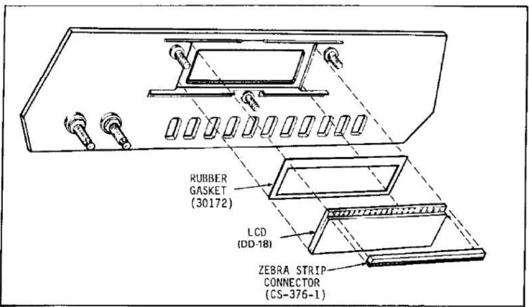
6-32. Perform the following procedure, referring to Figure 6-4, to replace the display of the Model 169.
a. Remove the case cover as explained in Paragraph 6-9.
b. Remove the three 3/8" pal nuts holding PC-509 to the front panel.
c. Separate PC-509 from the front panel being careful of the LCD display (Keithley Part No. DD-18) as it will be loose and may fall out of the front panel.
text_image
RUBBER GASKET (30172) LCD (DD-18) ZEBRA STRIP CONNECTOR (CS-376-1)FIGURE 6-2. LCD Assembly.
TABLE 6-1 Power Supply Checks
| STEP | ITEM/COMPONENT | REQUIRED CONDITION* | REMARKS |
| 1 | Battery Voltage | 7.5V min. | |
| 2 | CR105 | 0.5V drop max. | |
| 3 | U102, pin 40 and 15 | 7.0V min. | Supply to U102 |
| 4 | C107 | 2.4 to 3.2V | Output of U102(Analog Gnd) |
| 5 | C113 | 0.8 to 2.6V | Output of U102(Digital Gnd) |
| *Above checks with fresh batteries and power switch ON. | |||
TABLE 6-2 A/D Converter
| STEP | ITEM/COMPONENT | REQUIRED CONDITIONS* | REMARKS |
| 1 | Power ON, 200mVDC Range | ||
| 2 | Display | Short input, 00.0 ±ld | Zero Check |
| 3 | Reference (U102, pin 5) | Nominally 98mV using voltmeter with 10MΩ Input Impedance | High Impedance reference |
| 4 | Ratio test | Short U102 pin 5 to pin 10 | Connects reference to input |
| 5 | Display | 100.0 ±2d | If steps 3 and 5 are correct A/D Converter is functioning properly |
| 6 | U106, Pin 3 | 40kHz ±6kHz** Approx. 5Vp-p | Clock check |
| 7 | External Voltage Source | Apply +190.0mVAC | Calibration point |
| 8 | U102 Pin 14 to Input Lo | See waveform (Figure 6-3) | Integrator Check |
| *Measurements made with respect to input lo **Non-symmetrical in most cases | |||
line
| Time Interval | Voltage Level | | ------------- | ------------- | | 0 | -0.63V Normal | | 100ms | Signal Intercate | | 190ms | Reference Intercate | | 110ms | Autozero of next Conversion |FIGURE 6-3. Integrator Waveform.
TABLE 6-3
Display Driver
| STEP | ITEM/COMPONENT | REQUIRED CONDITIONS | REMARKS |
| 1 | Power ON | ||
| 2 | U102 pin 40 to pin 4 | 4.0 to 6.0 Volts | Digital Supply |
| 3 | U102 pin 3 to Input Lo | 40kHz ±6kHzApprox. 5Vp-p | Clock Check |
| 4 | U102 pin 20 to Input Lo | Approx. 50Hz Square wave, approx. 5Vp-p | |
| 5 | U102 - any display driver line | Approx. 50Hz Square wave, approx. 5Vp-p | In phase with backplane for segment off, Out of phase with backplane for segment on |
| 6 | U104, U105, U106, decimal point and annunciator driver lines | Approx. 50Hz square wave, approx. 5Vp-p |
TABLE 6-4 AC Converter
| STEP | ITEM/COMPONENT | REQUIRED CONDITIONS | REMARKS |
| 1 | Power ON, 200mVAC Range | ||
| 2 | U101 pin 7 to pin 4 | 7V min. | Supply Voltage |
| 3 | External Voltage Source | Apply 100mVAC at 100Hz | Calibrated Input |
| 4 | C108 | 98mVDC Nominal using 10MΩ input impedance voltmeter | High Impedance DC output |
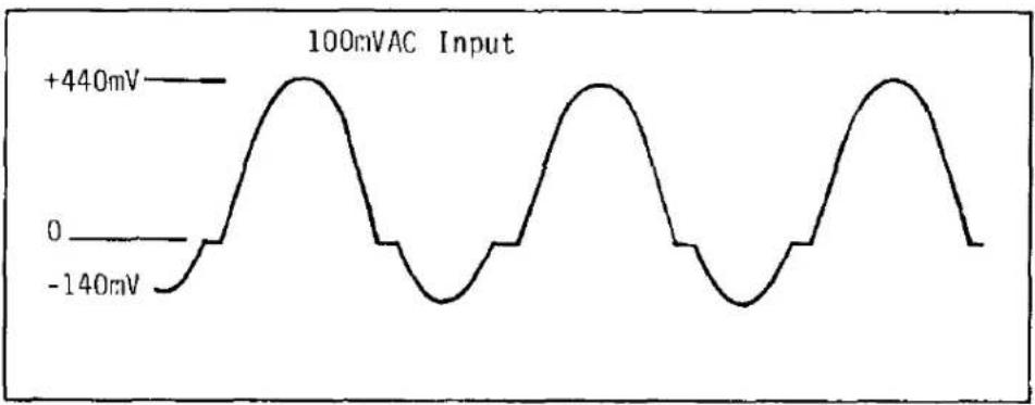
| 5 | U101 pin 6 to Input Lo | See Waveform (Figure 6-4) | |
| 6 | Short Input | ||
| 7 | U101 pin 6 to Input Lo | ±5mVDC offset max. |
line
| Time (ms) | Voltage (mV) | | --------- | ------------ | | 0 | -140 | | 100 | +440 |FIGURE 6-4. AC/DC Converter Waveform.
TABLE 6-5 Reference Source
| STEP | ITEM/COMPONENT | REQUIRED CONDITIONS | REMARKS |
| 1 | Power ON | ||
| 2 | U102 pin 40 to Input Lo | 2.4 to 3.2 VDC | Output of U102 (Analog Supply) |
| 3 | VR101 (<100pf probe) | 1.2 to 1.25V | Reference Source |
| 4 | R102 pin 8 to Input Lo | Nominally 100mVDC using voltmeter with ≥10MΩ input impedance |
TABLE 6-6 Ohms Circuit
| STEP | ITEM/COMPONENT | REQUIRED CONDITIONS* | REMARKS |
| 1 | Power OFF, DCV function, all range buttons out | ||
| 2 | RT101 | 1.0KΩ to 3.0KΩ (can now be checked in circuit)* | Resistance Check |
| 3 | Reference Resistors | R108 thru R113 can be checked in circuit for 0.1% accuracy | R108 affects 200Ω rangeR109 affects 2KΩ rangeR110 affects 20KΩ rangeR111 affects 200KΩ rangeR112 affects 2000KΩ rangeR113 affects 20MΩ range |
| 4 | Power ON, 200Ω range, Input open | ||
| 5 | Q101 | >2 Volts across emitter - collector junction | Voltage drop check |
| *Do not remove RT101 unless absolutely necessary because the leads fall off device easily while soldering. | |||
d. Make sure the rubber gasket is in place before placing the new display in the slot of the front panel.
e. The zebra strip should be installed after the new display is placed in the front panel window. Care must be taken to assure the zebra strip is kept clean. The zebra strip should be aligned such that the black stripes contact the conductors on the display and the conductors on PC-509.
f. Reassemble PC-509 and the front panel using the three 3/8" pal nuts. Tighten them until they are snug.
g. Turn the unit "ON" and check the display to see that it is working properly. If the zebra strip is not aligned properly or if it is dirty there will be some segments on the display that will not light.
6-33. BATTERY REPLACEMENT.
6-34. The low battery indicator will automatically come on with approximately 5% of battery life remaining (20 hours for carbon-zinc and 40 hours for alkaline cells). Replace per directions in Paragraph 2-6.
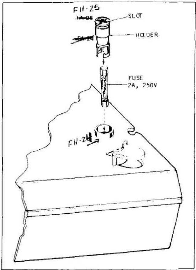
6-35. CURRENT FUSE REPLACEMENT (Figure 6-5).

WARNING
To prevent a shock hazard, disconnect all circuits from the Model 169 INPUT terminals before removing current fuse.
6-36. To remove the current fuse, turn the DMM over and lay it carefully on its top. Insert a small screwdriver blade into the slot on the fuse holder, press gently and turn 1/4-turn counter-clockwise. Lift the holder and fuse out of the receptacle. The fuse can now be removed for checking or replacement. Replace with one of the following types:
a. U.S.A. Use - 3AG, 250V, 2A, Normal Blow
b. Europe Use - 5 x 20mm, 250V, 2A, Normal Blow
text_image
FH-25 FA-25 SLOT HOLDER FUSE 2A, 250V FH-24FIGURE 6-5. Current Fuse Removal/Replacement.

Installing a higher rated fuse than the one specified could result in damage to the instrument.
SECTION 7. REPLACEABLE PARTS
7-1. GENERAL.
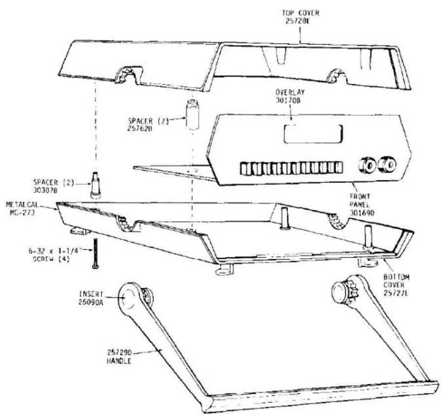
7-2. This section contains information for ordering replacement parts. Panel and covers are shown separately on Figure 7-1. The Replaceable Parts List is arranged in alphabetical order of the Circuit Designations of the components.
7-3. ORDERING INFORMATION
7-4. To place an order or to obtain information concerning replacement parts contact your Keithley representative or the factory. See the inside front cover for addresses. When ordering, include the following information:
a. Instrument Model Number.
b. Instrument Serial Number.
c. Part Description.
d. Circuit Designation (if applicable).
c. Keithley Part Number.
7-5. FACTORY SERVICE.
7-6. If the instrument is to be returned to the factory for service, please complete the Service Form which follows this section, and return it with the instrument.
7-7. SCHEMATIC.
7-8. The Model 169 3-1/2 Digit DMM: Schematic No. 30180D.
7-9. COMPONENT LAYOUT.
7-10. Model 169 PC-508, Component Layout No. 30176D.
7-11. MODEL 1699 SPARE PARTS KIT.
7-12. A spare parts kit is available that contains a complement of spare parts that can maintain up to ten Model 169's for approximately one year. A list of the spare parts is given in Table 7-1.
TABLE 7-1 Model 1699 Parts List
| Qty. | Keithley P/N | Schematic Designation |
| 2 | DZ-62* | VR101 |
| 2 | FH-12 | Fuse Holder |
| 5 | FU-13 | F101 (3AG) |
| 5 | FU-48 | F101 (5mm x 20mm) |
| 1 | IC-1028 | U103 |
| 1 | IC-226* | U104, U105 |
| 2 | IC-227 | U101 |
| 1 | IC-228* | U106 |
| 1 | LSI-22* | U102 |
| 1 | R-277-9M | R113 |
| 3 | RF-28 | CR101 thru CR104 |
| 2 | RF-34 | CR106, CR107 |
| 1 | RF-39 | CR105 |
| 1 | RT-5 | RT101 |
| 3 | TG-47 | Q101, Q102 |
*Anti-Static Protection and Handling required. Refer to Section 6 of this Manual for Special Handling Procedures for Static-Sensitive Devices.
Table 7-2 REPLACEABLE PARTS LIST
| Circuit Desig. | Description | Keithley Part No. |
| BT101 thru BT106 | Battery, 1.5V, "C" cell, Carbon Zinc | BA-6 |
| C101 | Cap., .1uF, 160V, Metalized Polypropylene | C-306-.1 |
| C102 | Cap., .22uF, 100V, Metalized Polyester | C-305-.22 |
| C103 | Cap., .047uF, 100V, Metalized Polyester | C-305-.047 |
| C104 | Cap., .1uF, 100V, Metalized Polyester | C-305-.1 |
| C105 | Cap., 4.7uF, 25V, Aluminum Electrolytic | C-314-4.7 |
| C106 | Cap., .1uF, 100V, Metalized Polyester | C-305-.1 |
| C107 | Cap., 4.7uF, 25V, Aluminum Electrolytic | C-314-4.7 |
| C108 | Cap., 1.0uF, 16V, Aluminum Electrolytic | C-325-1 |
| C109 | Cap., .02uF, 1000V, Ceramic Disc | C-298-.02 |
| C110 | Cap., 3.3pF, 1500V, Ceramic | C-308-3.3P |
| C111 | Cap., .047uF, 100V, Metalized Polyester | C-305-.047 |
| C112 | Cap., 110pF, 500V, Silver Mica | C-320-110P |
| C113 | Cap., 4.7uF, 25V, Aluminum Electrolytic | C-314-4.7 |
| C114 | Cap., .22uF, 100V, Metalized Polyester | C-305-.22 |
| C115 | Cap., 3900pF, 1000V, Ceramic Disc | C-64-3900P |
| C116 | Cap., 4.7uF, 25V, Aluminum Electrolytic | C-314-4.7 |
| C117 | Cap., Adjustable (1.5pF, nominal) | C-184 |
| C118 | Cap., 0.1uF, 50V, Ceramic Film | C-237-.1 |
| CR101 | Rectifier, Silicon, 75mA, 75V | RF-28 |
| CR102 | Rectifier, Silicon, 75mA, 75V | RF-28 |
| CR103 | Rectifier, Silicon, 75mA, 75V | RF-28 |
| CR104 | Rectifier, Silicon, 75mA, 75V | RF-28 |
| CR105 | Rectifier, Germanium 15mA, 25V | RF-39 |
| CR106 | Rectifier, Silicon, 3A, 50V | 32453 |
| CR107 | Rectifier, Silicon, 3A, 50V | 32453 |
| DS101 | Liquid Crystal DisplayZebra Connector Strip | DD-18CS-376-1 |
| F101 | Fuse, 2A, 250V, 3AG (U.S. Models) | FU-13 |
| F101 | Fuse, 2A, 250V, 5 x 20mm (European Models) | FU-48 |
| J1001 | Banana Jack, Red | BJ-11-2 |
| J1002 | Banana Jack, Black | BJ-11-0 |
| J1003 | Battery Connector | BH-28 |
| Q101 | Transistor, NPN | TG-47 |
| Q102 | Transistor, NPN | TG-47 |
Table 7-2 REPLACEABLE PARTS LIST (Cont.)
| Circuit Desig. | Description | Keithley Part No. |
| R101 | Potentiometer, 500 ohm | RP-97-500 |
| R102 | Thick Film Resistor Network | TF-93 |
| R103 | Resistor, 1M ohm, 10%, 1W, Comp | R-2-1M |
| R104 | Resistor, 10k ohm, .1%, .1W, MtF | R-283-10k |
| R105 | Resistor, 4.71k ohm, .1%, .1W, MtF | R-283-4.71k |
| R106 | Thick Film Resistor Network | TF-92 |
| R107 | Resistor, 100k ohm, 10%, 2W, Comp. | R-3-100k |
| R108 | Resistor, 100.1 ohm, .1%, .1W, MtF | R-283-100 |
| R109 | Resistor, 900 ohm, .1%, .1W, MtF | R-283-900 |
| R110 | Resistor, 9k ohm, .1%, .1W, MtF | R-283-9k |
| R111 | Resistor, 90k ohm, .1%, .1W, MtF | R-283-90k |
| R112 | Resistor, 900k ohm, .1%, .1W, MtF | R-283-900k |
| R113 | Resistor, 9M ohm, .08%, 2W, CMtF | R-277-9M |
| R114 | Resistor, Dual | R-278 |
| R115 | Resistor, 9 ohm, .5%, 1/2W, MtF | R-61-9 |
| H116 | Resistor, 90 ohm, .1%, 1/8W, MtF | R-179-90 |
| R117 | Resistor, 900 ohm, .1%, .1W, MtF | R-283-900 |
| RT101 | Thermistor, 2k ohm, 40%, 8mA, 500V, PTC | RT-5 |
| S101 | Switch, 12 Station, Pushbutton | 30314B SW-H160 |
| U101 | Low-Power JFET-Input OP-AMP | IC-277 |
| U102 | 3-1/2 Digit Single Chip A/D Converter | 32440A - LSI-22 |
| U103 | CMos Quad 2-Input NAND Gate | IC-102* |
| U104 | CMos Quad Exclusive-OR Gate | IC-226* |
| U105 | CMos Quad Exclusive-OR Gate | IC-226* |
| U106 | CMos Quad Exclusive-NOR Gate | IC-228* |
| VR101 | Diode, Low voltage ref, 1.2V, 10mA | DZ-62* |
| VR102 | Diode, Zener, 9.1V nominal, .25W | DZ-14 |
*Anti-static protection and handling required.
text_image
TOP COVER 25728E OVERLAY 30170B SPACER (2) 25762B SPACER (2) 303078 METAL CAL MC-27J 6-32 x 1-1/4" SCREW (4) FRONT PANEL 301690 BOTTOM COVER 25727L INSERT 25090A 257290 HANDLEFIGURE 7-1. Covers and Panels.
text_image
Q0BIOE 1 H1 RANGE SWITCHING 2 2DO 2K 2000K 200K 2000K C16 390V-4 200K R12 R12 R12 R12 R12 R12 R12 R12 R12 R12 R12 R12 R12 R12 R12 R12 R12 R12 R12 R12 R12 R12 R12 R12 R12 R11 R11 R11 R11 R11 R11 R11 R11 R11 R11 R11 R11 R11 R11 R11 R10 R10 R10 R10 R10 R10 R10 R10 R10 R10 R10 R10 R10 R10 R10 R10 R10 R10 R10 R10 R10 R10 R10 R10 R10 R15 R15 R15 R15 R15 R15 R15 R15 R15 R15 R15 R15 R15 R15 R15 R15 R15 R15 R15 R15 R15 R15 R15 R15 R15 R14 R14 R14 R14 R14 R14 R14 R14 R14 R14 R14 R14 R14 R14 R14 R14 R14 R14 R14 R14 R14 R14 R14 R14 R14 R13 R13 R13 R13 R13 R13 R13 R13 R13 R13 R13 R13 R13 R13 R13 R13 R13 R13 R13 R13 R13 LICOS 7.8VAC 7.8VAC 7.8VAC 7.8VAC 7.8VAC 7.8VAC 7.8VAC 7.8VAC 7.8VAC 7.8VAC 7.8VAC 7.8VAC 7.8VAC 7.8VAC 7.8VAC 7.8VAC 7.8VAC 7.6VAC 7.6VAC 7.6VAC 7.6VAC 7.6VAC 7.6VAC 7.6VAC 7.6VAC 7.6VAC 7.6VAC 7.6VAC 7.6VAC 7.6VAC 7.6VAC 7.6VAC 7.6VAC 7.6VAC 6.9VAC 6.9VAC 6.9VAC 6.9VAC 6.9VAC 6.9VAC 6.9VAC 6.9VAC 6.9VAC 6.9VAC 6.9VAC 6.9VAC 6.9VAC 6.9VAC 6.9VAC 6.9VAC 6.9VAC 5.9VAC 5.9VAC 5.9VAC 5.9VAC 5.9VAC 5.9VAC 5.9VAC 5.9VAC 5.9VAC 5.9VAC 5.9VAC 5.9VAC 5.9VAC 5.9VAC 5.9VAC 5.9VAC 5.9V AC/DC/DC/DC/DC/DC/DC/DC/DC/DC/DC/DC/DC/DC/DC/DC/DC/DC/DC/DC/DC/DC/DC/DC/DC/DC/DC/DC/DC/DC/DC/DC/DC/DC/DC/DC/DC/DC/DC/DC/DC/DC/DC/DC/DC/DC/DC/DC/DC/DC/DC/ DC/DC/DC/DC/DC/DC/DC/DC/DC/DC/DC/DC/DC/DC/DC/DC/DC/DC/DC/DC/DC/DC/DC/DC/DC/DC/DC/DC/DC/DC/DC/DC/DC/DC/DC/DC/DC/DC/DC/DC/DC/DC/DC/DC/DC/DC/DC/DC/DC/DC/NCI/S/C/C/C/C/C/C/C/C/C/C/C/C/C/C/C/C/C/C/C/C/C/C/C/C/C/C/C/C/C/C/C/C/C/C/C/C/C/C/C/C/C/C/C/C/C/C/C/C/C/C/C/C/C/C/C/C/C/C/C/C/C/C/C/C/C/C/C/C/C/C/C/C/C/C/C/C/C/C/C/C/C/C/C/C/C/C/C/C/C/C/C/C/C/C/C/C/C/C/C/C-C/A/B/D/D/D/D/D/D/D/D/D/D/D/D/D/D/D/D/D/D/D/D/D/D/D/D/D/D/D/D/D/D/D/D/D/D/D/D/D/D/D/D/D/D/D/D/D/D/D/D/D/D/D/D/D/D/D/D/D/D/D/D/D/D/D/D/D/D/D/D/D/D/D/D/D/D/D/D/D/D/D/D/D/D/D/D/D/D/D/D/D/D/D/D/D/D/D/D/D/D/D/D/A/LA/LA/LA/LA/LA/LA/LA/LA/LA/LA/LA/LA/LA/LA/LA/LA/LA/LA/LA/LA/LA/LA/LA/LA/LA/LA/LA/LA/LA/LA/LA/LA/LA/LA/LA/LA/LA/LA/LA/LA/LA/LA/LA/LA/LA/LA/LA/LA/LA/LA/La/La/La/La/La/La/La/La/La/La/La/La/La/La/La/La/La/La/La/La/La/La/La/La/La/La/La/La/La/La/La/La/La/La/La/La/La/La/La/La/La/La/La/La/La/La/La/La/La/La/LaN/A/A/A/A/A/A/A/A/A/A/A/A/A/A/A/A/A/A/A/A/A/A/A/A/A/A/A/A/A/A/A/A/A/A/A/A/A/A/A/A/A/A/A/A/A/A/A/A/A/A/A/A/A/A/A/A/A/A/A/A/A/A/A/A/A/A/A/A/A/A/A/A/A/A/A/A/A/A/A/A/A/A/A/A/A/A/A/A/A/A/A/A/A/A/A/A/A/A/A/A-A/B/T/RD/RD/RD/RD/RD/RD/RD/RD/RD/RD/RD/RD/RD/RD/RD/RD/RD/RD/RD/RD/RD/RD/RD/RD/RD/RD/RD/RD/RD/RD/RD/RD/RD/RD/RD/RD/RD/RD/RD/RD/RD/RD/RD/RD/RD/RD/RD/RD/RD/RD/Rd/T/T/T/T/T/T/T/T/T/T/T/T/T/T/T/T/T/T/T/T/T/T/T/T/T/T/T/T/T/T/T/T/T/T/T/T/T/T/T/T/T/T/T/T/T/T/T/T/T/T/T/T/T/T/T/T/T/T/T/T/T/T/T/T/T/T/T/T/T/T/T/T/T/T/T/T/T/T/T/T/T/T/T/T/T/T/T/T/T/T/T/T/T/T/T/T/T/T/T/T T/S T/S T/S T/S T/S T/S T/S T/S T/S T/S T/S T/S T/S T/S T/S T/S T/S T/S T/S T/S T/S T/S T/S T/S T/S T/S T/S T/S T/S T/S T/S T/S T/S T/S T/S T/S T/S T/S T/S T/S T/S T/S T/S T/S T/S T/S T/S T/S T/S T/S T/F /T /T /T /T /T /T /T /T /T /T /T /T /T /T /T /T /T /T /T /T /T /T /T /T /T /T /T /T /T /T /T /T /T /T /T /T /T /T /T /T /T /T /T /T /T /T /T /T /T /T /N A/B C D E N A B C D E N A B C D E N A B C D E N A B C D E N A B C D E N A B C D E N A B C D E N A B C D E N A B C D E N A B C D E N A B C D E N A B C D E N A B C D E N A B C D E N A B C D E N A B C D E N A B C D E-N A B C D E N A B C D E N A B C D E N A B C D E N A B C D E N A B C D E N A B C D E N A B C D E N A B C D E N A B C D E N A B C D E N A B C D E N A B C D E N A B C D E N A B C D E N A B C D E N A B C C D E N A B C D E N A B C D E N A B C D E N A B C D E N A B C D E N A B C D E N A B C D E N A B C D E N A B C D E N A B C D E N A B C D E N A B C D E N A B C D E N A B C D E N A B C D E N A B C D E_N A B C D E N A B C D E N A B C D E N A B C D E N A B C D E N A B C D E N A B C D E N A B C D E N A B C D E N A B C D E N A B C D E N A B C D E N A B C D E N A B C D E N A B C D E N A B C D E N A B C DC M V M DC M V M DC M V M DC M V M DC M V M DC M V M DC M V M DC M V M DC M V M DC M V M DC M V M DC M V M DC M V M DC M V M DC M V M DC M V M DC M V M DC M V M DC M V M DC M V M DC M V M DC M V M DC M V M DC M V M DC M V M DC M VM DC M DC M DC M DC M DC M DC M DC M DC M DC M DC M DC M DC M DC M DC M DC M DC M DC M DC M DC M DC M DC M DC M DC M DC M DC M DC M DC M DC M DC M DC M DC M DC M DC M DC M DC M DC M DC M DC M DC M DC M DC M DC M DC M DC M DC M DC M DC M DC M DC M DC M DCM UOU UOU UOU UOU UOU UOU UOU UOU UOU UOU UOU UOU UOU UOU UOU UOU UOU UOU UOU UOU UOU UOU UOU UOU UOU UOU UOU UOU UOU UOU UOU UOU UOU UOU WDO WDO WDO WDO WDO WDO WDO WDO WDO WDO WDO WDO WDO WDO WDO WDO WDO WDO WDO WDO WDO WDO WDO WDO WDO WDO WDO WDO WDO WDO WDO WDO WDO WDO WDO WDO WDO WDO WDO WDO WDO WDO WDO WDO WDO WDO WDO WDO WDO WDO WOOW DO O DO O DO O DO O DO O DO O DO O DO O DO O DO O DO O DO O DO O DO O DO O DO O DO O DO O DO O DO O DO O DO O DO O DO O DO O DO O DO O DO O DO O DO O DO O DO O DO O DO O DO O DO O DO O DO O DO O DO O DO O DO O DO O DO O DO O DO O DO O DO O DO O DO O DOO UOU UOU UOU UOU UOU UOU UOU UOU UOU UOU UOU UOU UOU UOU UOU UOU UOU UOU UOU UOU UOU UOU UOU UOU UOU UOUS OUT OUT OUT OUT OUT OUT OUT OUT OUT OUT OUT OUT OUT OUT OUT OUT OUT OUT OUT OUT OUT OUT OUT OUT OUT OUT OUT OUT OUT OUT OUT OUT OUT OUT OUT OUT OUT OUT OUT OUT OUT OUT OUT OUT OUT OUT OUT OUT OUT OUT OUT OUT OUT OUT OUT OUT OUT OUT OUT OUT OUT OUT OUT OUT OUT OUT OUT OUT OUT OUT OUT OUT OUT OUT OUT OUT OUT OUT OUT OUT OUT OUT OUT OUT OUT OUT OUT OUT OUT OUT OUT OUT OUT OUT OUT OUT OUT OUT OUT OUTOUT OUT OUT OUT OUTOUT OUTOUT OUTOUT OUTOUTOUTOUTOUTOUTOUTOUTOUTOUTOUTOUTOUTOUTOUTOUTOUTOUTOUTOUTOUTOUTOUTOUTOUTOUTOUTOUTOUTOUTOUTOUTOUTOUTOUTOUTOUTOUTOUTOUTOUTOUTOUTOUTOUTOUTOUTOUTOUTOUTOUTOUTOUTOUTOUTOUTOUTOUTOUTOUTOUTOUTOUTOUTOUTOUTOUTOUTOUTOUTOUTOUTOUTOUTOUTOUTOUTOUTOUTOUTOUTOUTOUTOUTOUTOUTOUTOUTOUTOUTOUTOUTOUTOUTOUTOUTOUTOUTOUTOUTOUTUTOUTUTUTUTUTUTUTUTUTUTUTUTUTUTUTUTUTUTUTUTUTUTUTUTUTUTUTUTUTUTUTUTUTUTUTUTUTUTUTUTUTUTUTUTUTUTUTUTUTUTUTUTUTUTUTUTUTUTUTUTUTUTUTUTUTUTUTUTUTUTUTUTUTUTUTUTUTUTUTUTUTUTUTUTUTUTUTUTUTUTUTUTUTUTUTUTUTUTUTUTUTOT UTOT UTOT UTOT UTOT UTOT UTOT UTOT UTOT UTOT UTOT UTOT UTOT UTOT UTOT UTOT UTOT UTOT UTOT UTOT UTOT UTOT UTOT UTOT UTOT UTOT UTOT UTOT UTOT UTOT UTOT UTOT UTOT UTOT UTOT UTOT UTOT UTOT UTOT UTOT UTOT UTOT UTOT UTOT UTOT UTOT UTOT UTOT UTOT UTOT UTOT ATGTC TC TC TC TC TC TC TC TC TC TC TC TC TC TC TC TC TC TC TC TC TC TC TC TC TC TC TC TC TC TC TC TC TC TC TC TC TC TC TC TC TC TC TC TC TC TC TC TC TC TC TC TC TC TC TC TC TC TC TC TC TC TC TC TC TC TC TC TC TC TC TC TC TC TC TC TC TC TC TC TC TC TC TC TC TC TC TC TC TC TC TC TC TC TC TC TC TC TC TC TC SCHEMATE SCHEMATE SCHEMATE SCHEMATE SCHEMATE SCHEMATE SCHEMATE SCHEMATE SCHEMATE SCHEMATE SCHEMATE SCHEMATE SCHEMATE SCHEMATE SCHEMATE SCHEMATE SCHEMATE SCHEMATE SCHEMATE SCHEMATE SCHEMATE SCHEMATE SCHEMATE SCHEMATE SCHEMATE SCHEMATSCHEMATE SCHEMATE SCHEMATE SCHEMATE SCHEMATE SCHEMATE SCHEMATE SCHEMATE SCHEMATE SCHEMATE SCHEMATE SCHEMATE SCHEMATE SCHEMATE SCHEMATE SCHEMATE SCHEMATE SCHEMATE SCHEMATE SCHEMATE SCHEMATE SCHEMATE SCHEMATE SCHEMATE SCHEMATE SCHCMSCCHCMSCCHCMSCCHCMSCCHCMSCCHCMSCCHCMSCCHCMSCCHCMSCCHCMSCCHCMSCCHCMSCCHCMSCCHCMSCCHCMSCCHCMSCCHCMSCCHCMSCCHCMSCCHCMSCCHCMSCCHCMSCCHCMSCCHCMSCCHCMSCCHCMSCCHCMSCCHCMSCCHCMSCCHCMSCCHCMSCCHCMSCCHCMSCCHCMSCHTDMOMSOMSOMSOMSOMSOMSOMSOMSOMSOMSOMSOMSOMSOMSOMSOMSOMSOMSOMSOMSOMSOMSOMSOMSOMSOMSOMSOMSOMSOMSOMSOMSOMSOMSOMSOMSOMSOMSOMSOMSOMSOMSOMSOMSOMSOMSOMSOMSOMSOMSOMsCOMsCOMsCOMsCOMsCOMsCOMsCOMsCOMsCOMsCOMsCOMsCOMsCOMsCOMsCOMsCOMsCOMsCOMsCOMsCOMsCOMsCOMsCOMsCOMsCOMsCOMsCOMsCOMsCOMsCOMsCOMsCOMsCOMsCOMsCOMsCOMsCOMsCOMsCOMsCOMsCOMsCOMsCOMsCOMsCOMsCOMsCOMsCOMsCOMsCOMsCONTOCTCONTOCTCONTOCTCONTOCTCONTOCTCONTOCTCONTOCTCONTOCTCONTOCTCONTOCTCONTOCTCONTOCTCONTOCTCONTOCTCONTOCTCONTOCTCONTOCTCONTOCTCONTOCTCONTOCTCONTOCTCONTOCTCONTOCTCONTOCTCONTOCTCONTOCTCONTOCTCONTOCTCONTOCTCONTOCTCONTOCTCONTOCTCONTOCTCONTOCTConTOCTCONTOCTCONTOCTCONTOCTCONTOCTCONTOCTCONTOCTCONTOCTCONTOCTCONTOCTCONTOCTCONTOCTCONTOCTCONTOCTCONTOCTCONTOCTCONTOCTCONTOCTCONTOCTCONTOCTCONTOCTCONTOCTCONTOCTCONTOCTCONTOCTCONTOCTCONTOCTCONTOCTCONTOCTCONTOCTCONTOCTCONTOCTCONTOCTCON TO CT CON TO CT CON TO CT CON TO CT CON TO CT CON TO CT CON TO CT CON TO CT CON TO CT CON TO CT CON TO CT CON TO CT CON TO CT CON TO CT CON TO CT CON TO CT CON TO CT CON TO CT CON TO CT CON TO CT CON TO CT CON TO CT CON TO CT CON TO CT CON TO CT CON TO CT CON TO CT CON TO CT CON TO CT CON TO CT CON TO CT CON TO CT CON TO CT CON TO CT CON NO CO CO CO CO CO CO CO CO CO CO CO CO CO CO CO CO CO CO CO CO CO CO CO CO CO CO CO CO CO CO CO CO CO CO CO CO CO CO CO CO CO CO CO CO CO CO CO CO CO CO CO CO CO CO CO CO CO CO CO CO CO CO CO CO CO CO CO CO CO CO CO CO CO CO CO CO CO CO CO CO CO CO CO CO CO CO CO CO CO CO CO CO CO CO CO CO CO CO CO COCO RND RND RND RND RND RND RND RND RND RND RND RND RND RND RND RND RND RND RND RND RND RND RND RND RND RND RND RND RND RND RND RND RND RND RND RND RND RND RND RND RND RND RND RND RND RND RND RND RND RND RDN LAD LAD LAD LAD LAD LAD LAD LAD LAD LAD LAD LAD LAD LAD LAD LAD LAD LAD LAD LAD LAD LAD LAD LAD LAD LAD LAD LAD LAD LAD LAD LAD LAD LAD LAD LAD LAD LAD LAD LAD LAD LAD LAD LAD LAD LAD LAD LAD LAD LAD LAG LAD LAD LAD LAD LAD LAD LAD LAD LAD LAD LAD LAD LAD LAD LAD LAD LAD LAD LAD LAD LAD LAD LAD LAD LAD LAD LAD LAD LAD LAD LAD LAD LAD LAD LAD LAD LAD LAD LAD LAD LAD LAD LAD LAD LAD LAD LAD LAD LAD L ADL ANB ANB ANB ANB ANB ANB ANB ANB ANB ANB ANB ANB ANB ANB ANB ANB ANB ANB ANB ANB ANB ANB ANB ANB ANB ANB ANB ANB ANB ANB ANB ANB ANB ANB ANB ANB ANB ANB ANB ANB ANB ANB ANB ANB ANB ANB ANB ANB ANB ANB ANF ALNANINATOR SWITCHING ON OT OT OT OT OT OT OT OT OT OT OT OT OT OT OT OT OT OT OT OT OT OT OT OT OT OT OT OT OT OT OT OT OT OT OT OT OT OT OT OT OT OT OT OT OT OT OT OT OT OT OT OT OT OT OT OT OT OT OT OT OT OT OT OT OT OT OT OT OT OT OT OT OT OT OT OT OT OT OT OT OT OT OT OT OT OT OT OT OT OT OT OT OT OT OT OT OT OT OT OT ATN FAM FAM FAM FAM FAM FAM FAM FAM FAM FAM FAM FAM FAM FAM FAM FAM FAM FAM FAM FAM FAM FAM FAM FAM FAM FAM FAM FAM FAM FAM FAM FAM FAM FAM FAM FAM FAM FAM FAM FAM FAM FAM FAM FAM FAM FAM FAM FAM FAM FAM FFM G H G H H H H H H H H H H H H H H H H H H H H H H H H H H H H H H H H H H H H H H H H H H H H H H H H H H H H H H H H H H H H H H H H H H H H H H H H H H H H H H H H H H H H H H H H H H H H H H H H H H H H I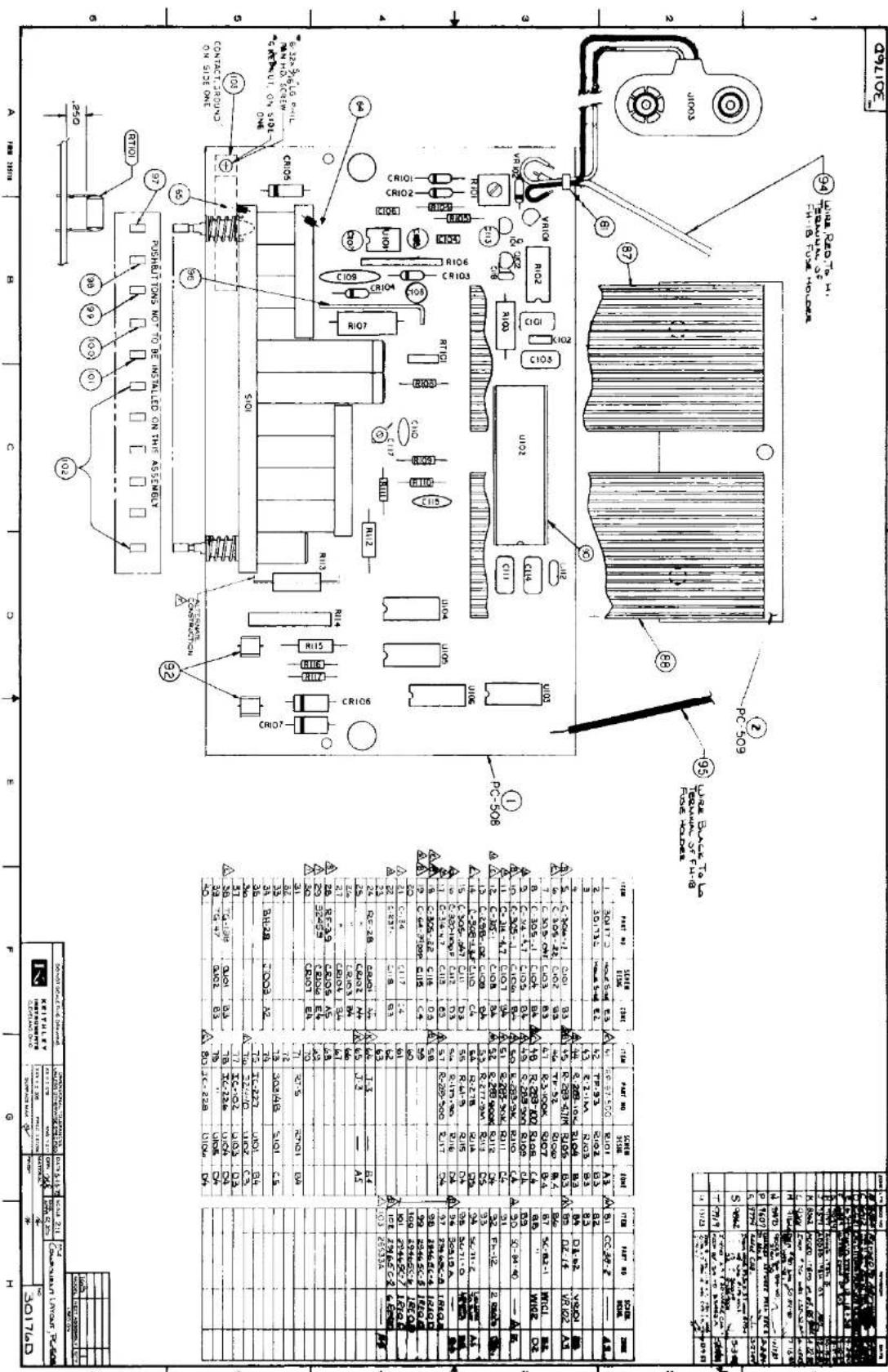
text_image
A HMI RUN B C D F G H P05H81 TONS NOT TO BE INSTALLED NO THIS ASSEBIT 250 CONTANT 262 ON ON: No. 5101 ON: No. 5102 ON: No. 5103 ON: No. 5104 ON: No. 5105 ON: No. 5106 ON: No. 5107 ON: No. 5108 ON: No. 5109 ON: No. 5110 ON: No. 5111 ON: No. 5112 ON: No. 5113 ON: No. 5114 ON: No. 5115 ON: No. 5116 ON: No. 5117 ON: No. 5118 ON: No. 5119 ON: No. 5120 ON: No. 5121 ON: No. 5122 ON: No. 5123 ON: No. 5124 ON: No. 5125 ON: No. 5126 ON: No. 5127 ON: No. 5128 ON: No. 5129 ON: No. 5130 ON: No. 5131 ON: No. 5132 ON: No. 5133 ON: No. 5134 ON: No. 5135 ON: No. 5136 ON: No. 5137 ON: No. 5138 ON: No. 5139 ON: No. 5140 ON: No. 5141 ON: No. 5142 ON: No. 5143 ON: No. 5144 ON: No. 5145 ON: No. 5146 ON: No. 5147 ON: No. 5148 ON: No. 5149 ON: No. 5150 ON: No. 5151 ON: No. 5152 ON: No. 5153 ON: No. 5154 ON: No. 5155 ON: No. 5156 ON: No. 5157 ON: No. 5158 ON: No. 5159 ON: No. 5160 ON: No. 5161 ON: No. 5162 ON: No. 5163 ON: No. 5164 ON: No. 5165 ON: No. 5166 ON: No. 5167 ON: No. 5168 ON: No. 5169 ON: No. 5170 ON: No. 5171 ON: No. 5172 ON: No. 5173 ON: No. 5174 ON: No. 5175 ON: No. 5176 ON: No. 5177 ON: No. 5178 ON: No. 5179 ON: No. 5180 ON: No. 5181 ON: No. 5182 ON: No. 5183 ON: No. 5184 ON: No. 5185 ON: No. 5186 ON: No. 5187 ON: No. 5188 ON: No. 5189 ON: No. 5190 ON: No. 5191 ON: No. 5192 ON: No. 5193 ON: No. 5194 ON: No. 5195 ON: No. 5196 ON: No. 5197 ON: No. 5198 ON: No. 5199 ON: No. 5200 ON: No. 5201 ON: No. 5202 ON: No. 5203 ON: No. 5204 ON: No. 5205 ON: No. 5206 ON: No. 5207 ON: No. 5208 ON: No. 5209 ON: No. 5210 ON: No. 5211 ON: No. 5212 ON: No. 5213 ON: No. 5214 ON: No. 5215 ON: No. 5216 ON: No. 5217 ON: No. 5218 ON: No. 5219 ON: No. 5220 On/In/In/In/In/In/In/In/In/In/In/In/In/In/In/In/In/In/In/In/In/In/In/In/In/In/In/In/In/In/In/In/In/In/In/In/In/In/In/In/In/In/In/In/In/In/In/In/In/In/In/ In/In/In/In/In/In/In/In/In/In/In/In/In/In/In/In/In/In/In/In/In/In/In/In/In/In/In/In/In/In/In/In/In/In/In/In/In/In/In/In/In/In/In/In/In/In/In/In/In/In/Ins/ PC-608 PC-609 (No) PC-609 (No) PC-609 (No) PC-609 (No) PC-609 (No) PC-609 (No) PC-609 (No) PC-609 (No) PC-609 (No) PC-609 (No) PC-609 (No) PC-609 (No) PC-609 (No) PC-636 (No) PC-636 (No) PC-636 (No) PC-636 (No) PC-636 (No) PC-636 (No) PC-636 (No) PC-636 (No) PC-636 (No) PC-636 (No) PC-636 (No) PC-636 (No) PC-636 (No) PLC-636 (No) PLC-636 (No) PLC-636 (No) PLC-636 (No) PLC-636 (No) PLC-636 (No) PLC-636 (No) PLC-636 (No) PLC-636 (No) PLC-636 (No) PLC-636 (No) PLC-COOL (No) PLC-COOL (No) PLC-COOL (No) PLC-COOL (No) PLC-COOL (No) PLC-COOL (No) PLC-COOL (No) PLC-COOL (No) PLC-COOL (No) PLC-COOL (No) PLC-COOL (No) PLC-COOL (No) PLC-COOL (No) FLC-COOL (No) FLC-COOL (No) FLC-COOL (No) FLC-COOL (No) FLC-COOL (No) FLC-COOL (No) FLC-COOL (No) FLC-COOL (No) FLC-COOL (No) FLC-COOL (No) FLC-COOL (No) FLC-COOL (No) FLC-COLO (No) FLC-COLO (No) FLC-COLO (No) FLC-COLO (No) FLC-COLO (No) FLC-COLO (No) FLC-COLO (No) FLC-COLO (No) FLC-COLO (No) FLC-COLO (No) FLC-COLO (No) FLC-COLO (No) FLC-COLO (No) FILC-COOL (No) FILC-COOL (No) FILC-COOL (No) FILC-COOL (No) FILC-COOL (No) FILC-COOL (No) FILC-COOL (No) FILC-COOL (No) FILC-COOL (No) FILC-COOL (No) FILC-COOL (No) FILC-COOL(No) FILC-COOL(No) FILC-COOL(No) FILC-COOL(No) FILC-COOL(No) FILC-COOL(No) FILC-COOL(No) FILC-COOL(No) FILC-COOL(No) FILC-COOL(No) FILC-COOL(No) FILC-COOL(Yes) FILC-COOL(Yes) FILC-COOL(Yes) FILC-COOL(Yes) FILC-COOL(Yes) FILC-COOL(Yes) FILC-COOL(Yes) FILC-COOL(Yes) FILC-COOL(Yes) FILC-COOL(Yes) FILC-COOL(Yes) PC-608 PC-609 PC-609(No) PC-609(No) PC-609(No) PC-609(No) PC-609(No) PC-609(No) PC-609(No) PC-609(No) PC-609(No) PC-609(No) PC-609(No) PC-609(No) PC-609(No) PC-636(No) PC-636(No) PC-636(No) PC-636(No) PC-636(No) PC-636(No) PC-636(No) PC-636(No) PC-636(No) PC-636(No) PC-636(No) PC-636(No) PC-636(No) PLC-SCORI- PLC-SCORI- PLC-SCORI- PLC-SCORI- PLC-SCORI- PLC-SCORI- PLC-SCORI- PLC-SCORI- PLC-SCORI- PLC-SCORI- PLC-SCORI- PLC-SCORI- PLC-SCORI- PLC-SCORI- PLC-SCORI- PLCA-SOCORI- PLCA-SOCORI- PLCA-SOCORI- PLCA-SOCORI- PLCA-SOCORI- PLCA-SOCORI- PLCA-SOCORI- PLCA-SOCORI- PLCA-SOCORI- PLCA-SOCORI- PLCA-SOCORI- PLCA-SOCORI- PLCA-SOCORI- PLCA-SOCORI- PLCA-SOCORi- PLCA-SOCORi- PLCA-SOCORi- PLCA-SOCORi- PLCA-SOCORi- PLCA-SOCORi- PLCA-SOCORi- PLCA-SOCORi- PLCA-SOCORi- PLCA-SOCORi- PLCA-SOCORi- PLCA-SOCORi- PLCA-SOCORi- PLCA-SOCORi- PLCA-SOCORi- FILCA-SOCORi- FILCA-SOCORi- FILCA-SOCORi- FILCA-SOCORi- FILCA-SOCORi- FILCA-SOCORi- FILCA-SOCORi- FILCA-SOCORi- FILCA-SOCORi- FILCA-SOCORi- FILCA-SOCORi- FILCA-SOCORi- FILCA-SOCFORI- FILCA-SOCFORI- FILCA-SOCFORI- FILCA-SOCFORI- FILCA-SOCFORI- FILCA-SOCFORI- FILCA-SOCFORI- FILCA-SOCFORI- FILCA-SOCFORI- FILCA-SOCFORI- FILCA-SOCFORI- FILCA-SOCFORI- FILCA-SOCFORI- FILCSA-SOCFORI- FILCSA-SOCFORI- FILCSA-SOCFORI- FILCSA-SOCFORI- FILCSA-SOCFORI- FILCSA-SOCFORI- FILCSA-SOCFORI- FILCSA-SOCFORI- FILCSA-SOCFORI- FILCSA-SOCFORI- FILCSA-SOCFORI- FILCSA-TOSL-HS. FILCSA-TOSL-HS. FILCSA-TOSL-HS. FILCSA-TOSL-HS. FILCSA-TOSL-HS. FILCSA-TOSL-HS. FILCSA-TOSL-HS. FILCSA-TOSL-HS. FILCSA-TOSL-HS. FILCSA-TOSL-HS. FILCSA-TOSL-HS. PC-608 PC-609 PC-609(No) PC-609(No) PC-609(No) PC-609(No) PC-609(No) PC-609(No) PC-609(No) PC-609(No) PC-609(No) PC-609(No) PC-609(No)KEITHLEY
SERVICE FORM
Model No. ____ Serial No. ____ Date ____
Name and Telephone No. ____
Company
List all control settings, describe problem and check boxes that apply to problem.
□Intermittent □Analog output follows display □Particular range or function bad; specify ____
☐ IEEE failure ☐ Obvious problem on power-up ☐ Batteries and fuses are OK
□Front panel operational □All ranges or functions are bad □Checked all cables
Display or output (circle one)
□Drifts □Unable to zero
□Unstable □Will not read applied input
□Overload
□Calibration only □C of C required
□Data required
(attach any additional sheets as necessary.)
Show a block diagram of your measurement system including all instruments connected (whether power is turned on or not). Also, describe signal source.
Where is the measurement being performed? (factory, controlled laboratory, out-of-doors, etc.)
What power line voltage is used? ____ Ambient Temperature? ____ °F
Relative humidity? ____ Other?
Any additional information. (If special modifications have been made by the user, please describe.)
Be sure to include your name and phone number on this service form.
Model 169 Digital Multimeter Addendum
INTRODUCTION
This addendum to the Model 169 Digital Multimeter Instruction Manual is being provided in order to supply you with the latest information in the least possible time. Please incorporate this information into the manual immediately.
Page 7-0; Replace Table 7-1 with the following:
Table 7-1. Model 1699 Parts List
| Quantity | Keithley P/N | Schematic Designation |
| 1 | DZ-62* | VR101 |
| 5 | FU-13 | F101 (3AG) |
| 5 | FU-48 | F101 (5mm × 20mm) |
| 1 | IC-102* | U103 |
| 1 | IC-226* | U104, U105 |
| 2 | IC-227 | U101 |
| 1 | IC-228* | U106 |
| 1 | LSI-122* | U102 |
| 1 | R277-9M | R113 |
| 3 | RF-28 | CR101 thru CR104 |
| 2 | RF-34 | CR106, CR107 |
| 1 | RF-39 | CR105 |
| 1 | RT-5 | RT-101 |
| 1 | TG-47 | Q102 |
*Anti-Static Protection and Handling required. Refer to the Model 169 Instruction Manual for Special Procedures for Static-Sensitive Devices.
MODEL 169 - RECOMMENDED SPARE PARTS
| PART NUMBER | DESCRIPTION | QTY |
| DZ-62 | Diode | 2 |
| IC-102 | Integrated Circuit | 1 |
| IC-226 | Integrated Circuit | 1 |
| IC-227 | Integrated Circuit | 2 |
| IC-228 | Integrated Circuit | 1 |
| LSI-22 | Integrated Circuit | 1 |
| R-277-9M | Resistor | 1 |
| RF-28 | Rectifier | 3 |
| RF-34 | Rectifier | 2 |
| RF-39 | Rectifier | 1 |
| RT-5 | Thermistor | 1 |
| TG-47 | Transistor | 3 |
| DD-18 C | Readout | 1 |
| C179-4.7 | Cap | 2 |
| BA-28 | Battery | 1 |
| 30169 | Front Panel | 1 |
| 30170 | Overlay | 1 |
KH/ntb:09/10/82
Model 169 Digital Multimeter Addendum
INTRODUCTION
This addendum to the Model 169 Digital Multimeter Instruction Manual is being provided in order to supply you with the latest information in the least possible time. Please incorporate this information into the manual immediately.
Page 7-0; Replace Table 7-1 with the following:
Table 7-1. Model 1699 Parts List
| Quantity | Keithley P/N | Schematic Designation |
| 1 | DZ-62* | VR101 |
| 5 | FU-13 | F101 (3AG) |
| 5 | FU-48 | F101 (5mm × 20mm) |
| 1 | IC-102* | U103 |
| 1 | IC-226* | U104, U105 |
| 2 | IC-227 | U101 |
| 1 | IC-228* | U106 |
| 1 | LSI-122* | U102 |
| 1 | R277-9M | R113 |
| 3 | RF-28 | CR101 thru CR104 |
| 2 | RF-34 | CR106, CR107 |
| 1 | RF-39 | CR105 |
| 1 | RT-5 | RT-101 |
| 1 | TG-47 | Q102 |
*Anti-Static Protection and Handling required. Refer to the Model 169 Instruction Manual for Special Procedures for Static-Sensitive Devices.
Model 169 Digital Multimeter Addendum
INTRODUCTION
This addendum to the Model 169 Digital Multimeter Instruction Manual is being provided in order to supply you with the latest information in the least possible time. Please incorporate this information into the manual immediately.
Page 7-0; Replace Table 7-1 with the following:
Table 7-1. Model 1699 Parts List
| Quantity | Keithley P/N | Schematic Designation |
| 1 | DZ-62* | VR101 |
| 5 | FU-13 | F101 (3AG) |
| 5 | FU-48 | F101 (5mm × 20mm) |
| 1 | IC-102* | U103 |
| 1 | IC-226* | U104, U105 |
| 2 | IC-227 | U101 |
| 1 | IC-228* | U106 |
| 1 | LSI-122* | U102 |
| 1 | R277-9M | R113 |
| 3 | RF-28 | CR101 thru CR104 |
| 2 | RF-34 | CR106, CR107 |
| 1 | RF-39 | CR105 |
| 1 | RT-5 | RT-101 |
| 1 | TG-47 | Q102 |
*Anti-Static Protection and Handling required. Refer to the Model 169 Instruction Manual for Special Procedures for Static-Sensitive Devices.