XT1600 - Trailer Meyer - Free user manual and instructions
Find the device manual for free XT1600 Meyer in PDF.


User questions about XT1600 Meyer
0 question about this device. Answer the ones you know or ask your own.
Ask a new question about this device
Download the instructions for your Trailer in PDF format for free! Find your manual XT1600 - Meyer and take your electronic device back in hand. On this page are published all the documents necessary for the use of your device. XT1600 by Meyer.
USER MANUAL XT1600 Meyer
natural_image
Exterior view of a three-wheeled flatbed trailer parked on snow, with no visible text or symbols.MODELS
XT2200
XT2200L
XT2200XL
MODELS
XT1600
XT1600L
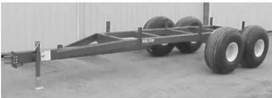
natural_image
Large industrial vehicle chassis with three large tires, displayed indoors (no visible text or symbols)DO NOT OPERATE EQUIPMENT UNTIL THIS MANUAL HAS BEEN READ AND UNDERSTOOD.
MEMBER

FEMA

text_image
Over 60 years of service to our customersMANUFACTURED BY
Meyer Mfg. Corp.
County Hwy. A West
P.Ó. Box 405
Dorchester, Wisconsin 54425-0405
Phone 715-654-5132 • FAX 715-654-5513
1-800-325-9103
www.meyermfg.com
E-mail: sales@meyermfg.com

text_image
MANUFACTURED IN DORCHESTER MILL BY MEYER®TABLE OF CONTENTS
Table of Contents 3
Introduction 4
Warranty 5
Safety 6
Safety Precautions. 7
Transporting 8
Use Safety Chain 8
Attaching Trailer with brakes To Tow Vehicle . . . . . . . . . . . . . . . . . . . . . . . 9
Farm implement tires. 9
Safety precautions 9
Maintenance Instructions. 10
Lubrication - Figure 2. 10
Inspection 10
Pack Wheel Bearings....11
Adjust Wheel Bearing Preload 11
Farm Implement Tires 11
Service & Maintenance Tips 11
Meyer Equipment Wheel Torque 12
Brake Maintenance 13
Bleeding Of Brakes 13
Tire inflation. 13
Repair parts 14
Models XT1600 & XT1600L Frame & O-Beam. 14
Model XT2200, XT2200L & XT2200XL Frame 16
Model XT2200, XT2200L & XT2200XL Frame 17
Model XT2200, XT2200L & XT2000XL O-Beam 18
Model XT2200, XT2200L & XT2000XL Axle & Wheels. 19
Hub For Models XT1600 & XT1600L 20
Hub For Models XT2200, XT2200L & XT2000XL 21
XT2200 Optional Brake Package. 22
Trailer And Box Mounting Specification Sheet 26
Specifications 27
INTRODUCTION
Congratulations on your purchase of a new Meyer farm equipment product. Undoubtedly you have given much consideration to your purchase and we're proud that you have selected Meyer. Pride in craftsmanship, engineering and customer service have made Meyer products the finest in the farm equipment industry today.
There is no substitute for quality. That is why thousands of people like you have purchased Meyer farm equipment. They felt it was the best equipment to serve their farming needs, now and in years to come. We ask that you follow our policy of “safety first,” and we strongly suggest that you read through the owner’s manual before operating your Meyer farm equipment.
Meyer Manufacturing Corporation wants to thank you for not compromising quality. We are determined to offer excellence in customer service as well as provide you with the very best value for your dollar.
REMEMBER:
FARM EQUIPMENT BUYERS TRUST THE NAME MEYER!
Sincerely,
All Employees of MEYER MANUFACTURING CORPORATION
Meyer Mfg. Corp. reserves the right to make improvements in design, or changes in specifications at any time, without incurring any obligation to owners of units previously sold.
This supersedes all previous published instructions.
IMPORTANT:
Complete Meyer Mfg. Corp. invoice and promptly forward a copy to Meyer Mfg. Corp. to validate the manufacturer's warranty. The product model and serial number are recorded on this certificate and below for proper identification of your Meyer Farm Trailer.
Model No. ____
Serial No. ____
Date of Purchase
At the back of this manual is the repair parts section. All replacement parts are to be obtained from or ordered through your Meyer dealership. When ordering repair parts, refer to the parts section and give complete information including quantity, correct part number, detailed description and even Model No. and Serial No. of the Meyer Farm Trailer which needs repair parts.
NOTE: All references to right hand (RH), left hand (LH), front and rear apply to the product as viewed from the rear of the trailer.
WARRANTY
Meyer Mfg. Corp. warrants new Meyer's trailers to be free from defects in material and workmanship under normal recommended use and service, as stated in the operator's manual, as follows:
- Meyer Mfg. will repair or replace F.O.B. Dorchester, WI, as Meyer Mfg. elects, any part of a new Meyer's trailer which is defective in material or workmanship.
a. Without charge for either parts or labor during the first year following delivery to the original retail customer, and;
b. Without charge for parts (not labor) during the second year following delivery to the original retail customer. - Warranty forms must be completed and returned to Meyer Mfg. Corp. for this warranty to be valid.
- This warranty is the sole and exclusive warranty which is applicable in connection with manufacture and sale of this product and Meyer Mfg. Corp. responsibility is limited accordingly.
SAFETY
A brief definition of signal words that are used in this manual is as follows.
DANGER
indicates an imminently hazardous situation which, if not avoided, WILL result in death or
serious injury.
WARNING
indicates a potentially hazardous situation which, if not avoided, COULD result in death or
serious injury, and includes hazards that are exposed when guards are removed.
CAUTION
indicates a potentially hazardous situation which, if not avoided, MAY result in minor or
moderate injury. It is also used to alert against unsafe practices.

WARNING
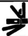

CRUSHING HAZARD
To prevent serious injury or death:
- Keep hands and body out of hitch area when attaching towing vehicle.
- Keep body clear of crush point between towing vehicle and load.
Part No. 46-0800-6

WARNING
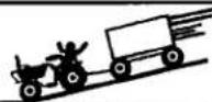
RUN-AWAY HAZARD
To prevent serious injury or death:
- Shift to lower gear before going down steep grades.
- Keep towing vehicle in gear at all times.
- Never exceed a safe travel speed.
Part No. 46-0800-7

WARNING
To prevent serious injury or death:
- Read and understand owner's manual before using. Review safety precautions annually.
• No riders allowed when transporting. - Securely attach to towing unit. Use a high strength appropriately sized hitch pin with a mechanical retainer and attach safety chain.
- Do not exceed 20 mph (33 kph). Slow down for corners and rough terrain.
• Do not drink and drive. - Before moving running gear, be sure required lights and reflectors are installed and working.
- Before maintenance or repair, stop vehicle, set parking brake, and remove ignition key.
- Place safety stands under frame and chock wheels before working on tires or running gear.
- Maintain wheel bolts at torque as recommended in the manual.
- If equipped with brakes, maintain proper adjustment.
Part No. 46-0800-8
NOTE: THESE DECALS ARE APPLIED TO MEYER'S
TRAILERS AND ARE INCLUDED IN THIS MANUAL FOR REFERENCE.
CAUTION
READ ALL DECALS ON THE TRAILER AND IN THIS MANUAL. KEEP THESE
DECALS CLEAN AND REPLACE ANY LOST OR DAMAGED DECALS. BECOME FAMILIAR WITH ALL TRACTOR CONTROLS.
SAFETY PRECAUTIONS

This symbol is used to call your attention to instructions concerning your personal safety. Be sure to observe and follow these instructions. Take time to be careful!
WARNING
BEFORE YOU ATTEMPT TO OPERATE THIS EQUIPMENT, READ AND STUDY THEFOLLOWING SAFETY INFORMATION. IN ADDITION, MAKE SURE THAT EVERY INDIVIDUAL WHO OPERATES OR WORKS WITH THE EQUIPMENT, WHETHER FAMILY MEMBER OR EMPLOYEE, IS FAMILIAR WITH THESE SAFETY PRECAUTIONS.
Require anyone who will operate this machine to read and understand this manual. Give necessary instructions.
DO NOT operate, service, inspect or otherwise handle this equipment until you have read this Owner's Manual and have been properly trained in its intended usage.
Do not allow minors (children) or inexperienced persons to operate this machine.
Do not allow riders on this machine at any time.
Inspect when first delivered and regularly thereafter; that all connections and bolts are tight and secure before operating.
Do not operate until all shields, covers and guards are in place.
Make certain area is clear of people, tools, and other objects before moving trailer.
Keep hands, feet and clothing away from moving parts. Loose or floppy clothing should not be worn by the operator.
Do not step on the trailer at any time.
Keep away from power lines. Contact with electric lines may result in serious injury or death by electrocution!
Use only properly rated running gear and tires.
Do not tow at speeds in excess of 20 MPH when transporting.
You must observe all applicable traffic laws when transporting on public roadways (where legal to do so). Check local laws for all highway lighting and marking requirements.
Always install a SMV emblem for transporting on roadways and keep this emblem clean and bright.
MEYER MFG. CORP. PROVIDES GUARDS FOR EXPOSED MOVING PARTS FOR THE OPERATOR'S PROTECTION; HOWEVER, SOME AREAS CANNOT BE GUARDED OR SHIELDED IN ORDER TO ASSURE PROPER OPERATION. THE OPERATOR'S MANUAL AND DECALS ON THE MACHINE ITSELF WARN YOU OF DANGERS AND MUST BE READ AND OBSERVED CLOSELY!
Study the Above Safety Rules
FAILURE TO HEED MAY RESULT IN SERIOUS PERSONAL INJURY
TRANSPORTING
DANGER
DO NOT OPERATE WHILE UNDER THE INFLUENCE OF ALCOHOL OR DRUGS.
Be certain your forage box is properly mounted to the trailer. Consult your dealer if you have any questions about the tie down kit from the manufacturer.
WARNING
INSPECT REGULARLY THATALL CONNECTIONS AND BOLTS ARE TIGHT AND SECURE BEFORE OPERATING. FAILURE TO HEED MAY RESULT IN SERIOUS PERSONAL INJURY OR DEATH.
WARNING
DO NOT TOW AT SPEEDS GREATER THAN 20 MPH. FAILURE TO HEED MAY RESULT IN SERIOUS PERSONAL INJURY OR DEATH.
Operating speed is dictated by the terrain over which you are traveling. Always use caution. Avoid traveling on slopes or hills that are unsafe.
Always disconnect the PTO drive shaft from the tractor and return it to its storage bracket on the unloading unit for transporting. Failure to do this may result in equipment damage.
WARNING
OBSERVE ALL APPLICABLETRAFFIC LAWS WHEN TRANSPORTING ON PUBLIC ROADWAYS. CHECK LOCAL LAWS FOR ALL HIGHWAY LIGHTING AND MARKING REQUIREMENTS.
WARNING
INSTALL A SMV EMBLEM ON REAR OF FORAGE BOX FOR TRANSPORTING ON ROADWAYS AND KEEP THIS EMBLEM CLEAN AND BRIGHT. FAILURE TO HEED MAY RESULT IN SERIOUS PERSONAL INJURY OR DEATH.
If you will travel on public roads and it is legal to do so, you must know all rules governing such operation. This will include lighting and brake requirements in addition to traffic rules. You may also be required to install a safety chain device on the running gear.
Check for traffic constantly. Be sure that no one is attempting to pass and that all traffic is sufficiently clear before making any turns.
WARNING
ALWAYS USE A SAFETY HITCH PIN WITH A LOCKING DEVICE.
USE SAFETY CHAIN
CAUTION
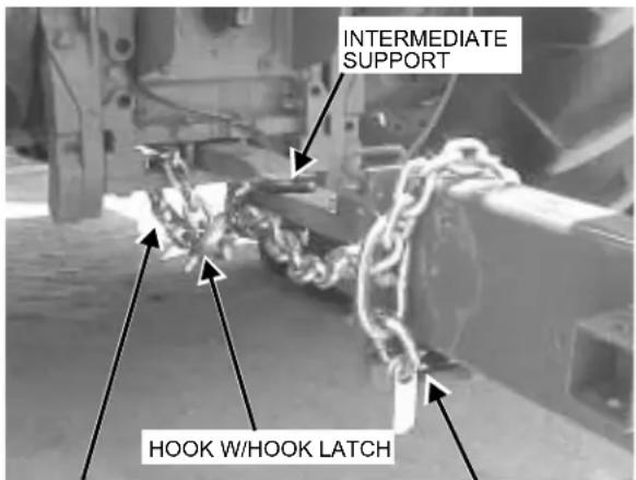
A SAFETY CHAIN MUST BE INSTALLED TO RETAIN THE CONNECTION BETWEEN TRACTOR (OR OTHER TOWING VEHICLE) AND SPREADER WHENEVER TRAVELING ON PUBLIC ROADS IN CASE THE HITCH CONNECTION WOULD SEPARATE. A SUGGESTED ATTACHMENT IS ILLUSTRATED ON FIGURE 1.
The chain must be strong enough to hold the weight of the loaded trailer. If using a grab hook at the end(s) of the chain to secure the chain to itself, a hook latch must be installed.
The length of the safety chain is not to be any longer than necessary to turn without interference. If any chain links or attachment hardware are broken or stretched, repair before using. Store chain so it does not corrode or become damaged. Do not use this chain for other implements because the strength and length of chain may not be adequate. Identify this chain for use on this particular trailer.
WARNING
ALWAYS TRAVEL UPHILL OR DOWNHILL ON INCLINES AND SLOPES TO PREVENT ROLLOVER
text_image
INTERMEDIATE SUPPORT HOOK W/HOOK LATCHTOWING MACHINE
ATTACHING POINT
ROUTE CHAIN THRU
LOOP UNDER TONGUE
(Use hook latch)
Figure 1. Safety Chain Installation
WARNING
BE SURE YOU HAVE
ADEQUATE CLEARANCE FOR YOUR LOADED TRAILER TO AVOID CONTACT WHEN TRAVELING UNDER ELECTRICAL POWER LINES. CONTACT CAN RESULT IN SEVERE ELECTRICAL SHOCK OR ELECTROCUTION.
ATTACHING TRAILER WITH BRAKES TO TOW VEHICLE
CAUTION
PLEASE NOTE THAT THESURGE BRAKES ARE TO BE USED FOR ASSISTING IN STOPPING ONLY AND ARE NOT TO BE RELIED ON AS THE ONLY MEANS FOR STOPPING THE TOWED PIECE OF EQUIPMENT. USE CAUTION AS SERIOUS INJURY OR DEATH COULD RESULT.
Attach the towing vehicle to the trailer using a proper sized hitch pin to handle the load being towed. Check that safety pins are inserted properly to prevent accidental uncoupling. Do not pull trailer if the hitch plates are damaged. Use a safety chain as instructed on page 8. Connect the breakaway chain from the actuator to the tow vehicle fastening to the bumper or hitch assembly. Allow extra slack for turning corners but not too much slack for the chain to be dragging on the pavement. Maintain as straight a connection to the tow vehicle as possible. The safety breakaway chain will only function after the hitch pin and safety chains have failed.
NOTE: The safety breakaway chain is not to act as a parking brake. Trailers with free backing brakes will not hold in reverse direction. To release the breakaway lever pry up on the spring clip to release lever
FARM IMPLEMENT TIRES
SAFETY PRECAUTIONS
Do's
- DO remove the valve core and deflate the tire before any work is performed.
- DO use the proper and approved tools to demount and mount the tire.
-
DO inspect all rim/wheel parts for wear, damage, cracks, rust or mismatched components. Destroy damaged or unserviceable parts.
-
DO inspect the tube and tire for cord or side damage, cuts or wear. Unrepairable damaged items must be discarded.
- DO check for mismatched components or tire and wheel sizes.
- DO lubricate tire with a non-flammable tire lubricant approved for that purpose.
- DO place tire and wheel in inflation cage or restraining device before inflating beyond 5 PSI.
- DO use an extension hose with a PSI gauge and clip on chuck when inflating the tire so you can stand to one side.
Don'ts
- DON'T work on a tire/wheel assembly before removing the valve core and completely deflating.
- DON'T re-inflate a tire that has been run flat or in an under inflated condition before removing and inspection.
- DON'T reuse damaged, defective worn or mismatched parts.
- DON'T rework, weld, heat or braze any rim /wheel parts for any reason.
- DON'T inflate any tire beyond 40 PSI to seat the beads. If beads are not seated at 40 PSI. STOP! Deflate and determine problem.
- DON'T hammer, strike or pry on a rim/wheel assembly that contains any inflation pressure.
- DON'T inflate a tire without using an inflation cage or restraining device.
- DON'T inflate beyond the maximum PSI specified for the tire or rim.
Study the Above Safety Rules
FAILURE TO HEED MAY RESULT IN SERIOUS PERSONAL INJURY OR DEATH.
MAINTENANCE INSTRUCTIONS
WARNING
BEFORE SERVICING OR INSPECTING THIS TRAILER, HAVE IT HITCHED TO A
TRACTOR WITH ENGINE OFF, KEYS REMOVED AND PARKING BRAKE SET OR CHOCK ALL FOUR WHEELS OF TRAILER.
WARNING
FAILURE TO COMPLY WITH OPERATING AND MAINTENANCE INSTRUCTIONS
MAY CAUSE SERIOUS PERSONAL INJURY.
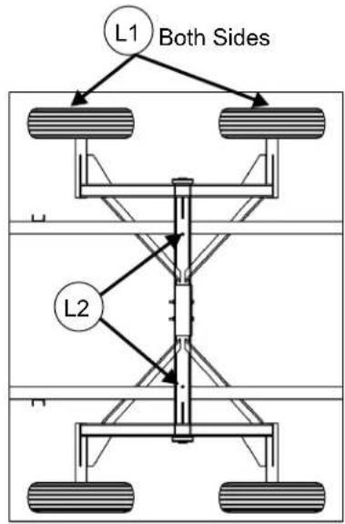
text_image
L1 Both Sides L2XT1600 &XT1600L TRAILERS TOP VIEW
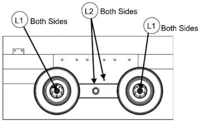
text_image
L1 Both Sides L2 Both Sides L1 Both SidesXT2200, XT2200L & XT2200XL
TRAILERS
SIDE VIEW
Figure 2. Lubrication Diagram
LUBRICATION - FIGURE 2.
| FREQUENCY ITEM LOCATION PROCEDURE | |||
| Every 2 Work Days Or 20 Loads | Tandem Wings | L2 | Jack up empty trailer off ground and support on adequate jack stands to relieve pressure and grease until it purges. |
| Annually | Wheel Bearings | L1 | Clean and pack hub bearings. Use quality grade of wheel bearing grease. See page 11. |
INSPECTION
| FREQUENCY ITEM PROCEDURE | ||
| Daily | Wheel Hub Lug Bolts | Check for proper torque as listed on page 12. |
| Wheel Hub Bearings | Check bearing play and adjust bearing preload if required. | |
| Tire Inflation | Check inflation as listed on page 13. | |
| Every 30 Days | All Fasteners And Connections | Check complete trailer for loose and fatigued fasteners. Check all pivots for play. Tighten or replace as required. |
| Annually | Tires | Check tires for wear and replace when necessary. |
| All Pivots And Bushings | Check for wear and repair as required. | |
WARNING
DO NOT TOW AT SPEEDS IN
EXCESS OF 20 MPH.
PACK WHEEL BEARINGS
- Chock all four wheels or hitch to tractor with engine off, key removed and parking brake set. Jack empty trailer off ground and support with adequate jack stands.
- Disassemble hub and remove all old grease. Clean bearings in non flammable solvent and dry.
- Reassemble hub and pack with quality wheel bearing grease.
- Adjust wheel bearing preload as described in the following instructions
ADJUST WHEEL BEARING PRELOAD
- Chock all four wheels or hitch to tractor with engine off, key removed and parking brake set. Jack empty trailer off ground and support with adequate jack stands.
- Push back and forth on each wheel assembly. If play is detected, bearings need adjusting.
- If adjusting bearings, it is suggested the bearings be repacked as described previously.
- Remove hub cap and remove cotter pin from spindle nut.
- Tighten spindle nut to remove all play. It should be snug and slight drag can be felt while rotating the wheel
- If the cotter pin hole in the spindle does not line up with the notch in spindle nut, back off the spindle nut only enough to line up. Reinstall cotter pin. If cotter pin is damaged, replace it.
- Replace hub cap and lower wheel to the ground.
FARM IMPLEMENT TIRES
SERVICE & MAINTENANCE TIPS
Agricultural tires are designed to carry a specified load at a specified inflation pressure when mounted on a specified width rim. When these conditions are met, the deflection of the tire carcass is in the optimum range and maximum tire performance can be expected. If this combination of design factors is altered for any reason, tire performance will be reduced.
CHECKING INFLATION
Inflation pressures should be checked at least every week. Recommended inflation Pressures based on total load on tires should be used. For accurate inflation use a special low-pressure gauge with one-pound gradations. Gauges should be checked occasionally for accuracy. Always use sealing valve caps to prevent loss of air.
TIRE OVERLOAD OR UNDER INFLATION
Tire overload or under inflation have the same effect of over-deflecting the tire. Under such conditions the tread on the tire will wear rapidly and unevenly, particularly in the shoulder area. Radial cracking in the upper sidewall area will be a problem. With under inflated drive tires in high torque applications sidewall buckles will develop leading to carcass breaks in the sidewall. While an under inflated drive tire may pull better in some soil conditions, this is not generally true and not worth the high risk of tire damage that such an operation invites.
OVER INFLATION
Over inflation results in an under-deflected tire carcass. The tread is more rounded, concentrates tread wear at the centerline area. Traction is reduced in high torque service because ground contact of the tread shoulder area is reduced and the harder carcass—with reduced flexing characteristics—does not work as efficiently. The tightly stretched over-inflated carcass is more subject to weather checking and impact break damage.
Higher tire loads are approved for intermittent service operations at reduced speed. Under such conditions inflation pressure must be increased to reduce tire deflection and assure full tire service life. See Page 13 for proper inflation.
USE OF PROPER WIDTH RIMS
Mention has been made of the importance of mounting tires on rims of the specified width. When this recommendation is not followed the following conditions can result:
USE OF A RIM WIDER THAN RECOMMENDED
Use of a wider rim results in flattening of the tread face. This feature may improve traction in some looser soil conditions. In hard soils, however, the flatter tread penetrates less effectively and tractive effort is reduced. Additional stresses concentrated in the shoulder area tend to increase the rate of shoulder
tread wear. By spacing the tire beads farther apart the sidewalls are forced to flex in an area lower than normal and this can result in circumferential carcass breaks and/or separation.
USE OF A RIM NARROWER THAN RECOMMENDED
This condition brings potential mounting problems because the rim shield or flange cover molded into most drive tire designs tends to interfere with the seating of the tire beads on a narrow rim. Once mounted on a narrow rim, the tire shield applies undue pressure on the rim flange, with possible tire sidewall separation or premature rim failure at the heel radius. On a narrow rim the tread of the tire is rounded. As with the over-inflated tire tread wear will be concentrated in the center area of the tread and traction in the field will be reduced.
ROADING OF FARM TIRES
Tractor tires operate most of the time in field conditions where the lugs can penetrate the soil, and where all portions of the tread make contact with the ground. In operating on hard roads with low inflation pressure there is an undesirable distortion of the tire during which the tread bars squirm excessively while going under and coming out from under the load. On highly abrasive or hard surfaces, this action wipes off the rubber of the tread bars or lugs and wears them down prematurely and irregularly.
If tires are to operate for any length of time on roads or other hard surfaces and the draft load is not great, it is advisable to increase the pressure in the tire to the maximum recommendation in order to reduce the movement of the tread bars that causes excessive wiping action.
Farm tractor and implement tires are designed for low-speed operations not exceeding 25 miles per hour. If tractors or implements are towed at high speeds on the highway high temperatures may develop under the tread bars and weaken the rubber
material and cord fabric. There may be no visible evidence of damage at the time. Later a premature failure occurs which experience shows was started by the overheated condition that developed when the unit was towed at a high speed.
CARE AND STORAGE OF TRACTOR AND IMPLEMENT TIRES
All tires should be stored indoors in a cool, dark, dry area free from drafts. Both heat and light are sources of oxidation on the tire surfaces—a result of which is crazing and weather checking. Tires should never be stored on oily floors or otherwise in contact with solvents, oil or grease. Further, tires should not be stored in the same area with volatile solvents. Such solvents are readily absorbed by rubber and will damage and weaken it.
Tires should be stored away from electric motors, generators, arc welders, etc.. since these are active sources of ozone. Ozone attacks rubber—to cause crazing and weather checking.
Unmounted tires should be stored vertically on tread. If stored for an extended period, tires should be rotated periodically to reduce stress concentrations in the area of ground contact. Tires should not be stored flat and “stove piped” as they will become squashed and distorted, making mounting on the rim difficult—particularly for tubeless tires.
Inflated tires mounted on rims should be stored under conditions noted above, with inflation pressure reduced to 10 PSI.
MEYER EQUIPMENT WHEEL TORQUE
| BOLT/STUD SIZE | SOCKET SIZE | PRESS FORMED WHEEL CENTER | BOLT TYPE | HEAVY DUTY WHEEL CENTER |
| 12 | 34 | 80 ft lbs | Lug Bolt | 85 ft lbs |
| 9/16 | 7/8 | 80 ft lbs | Lug Bolt | 120 ft lbs |
| 5/8 | 15/16/1-1/16 | 100 ft lbs | Bevel or Flange Nut | 160 ft lbs |
| 34 | 1-1/8 / 1-1/2 | Flange Nut | 378 ft lbs |
TIRE INFLATION
| TIRE SIZE | PLY | PSI |
| 11L-15 | 8 | 36 |
| 12.5L-15 | 8 | 36 |
| 12.5L-15 | 12 | 52 |
| 14L-16 | 12 | 44 |
| 16.5L-16 | 10 | 36 |
| 19LX16.1 | 10 | 32 |
| 21.5L-16.1 | 18 | 44 |
| 11R/22.5 | used truck | 75 |
| 425/65X22.5 | used truck | 75 |
| 28L-26 | 16 | 28 |
BRAKE MAINTENANCE
Before towing, check that the brake fluid reservoir is maintained to at least half full. If not refill with DOT 3 brake fluid. Check complete system for any leaks and repair as needed. Examine actuator for bent parts or excessive wear. Straighten or replace any worn parts as needed. Check to see that all mounting bolts and fasteners are tight.
Excessive actuator travel (over one inch) is a sign that the brakes need to be adjusted. Jack wheel/tire off of the ground and rotate tire in the forward direction. Remove access hole cover plate on the lower back side of the backing plate and adjust the brakes until drag is felt on the wheel when spinning in the forward direction. Back off adjuster twenty clicks (notches) for two-wheel brake systems and fifteen clicks (notches) for four wheel brake systems. Adjust all wheels being sure to rotate in the forward direction only when adjusting to ensure proper adjustment.
WARNING
ANY CORROSIVE
MATERIALS (SALTWATER, FERTILIZERS) ARE DESTRUCTIVE TO METALS. TO PROPERLY MAINTAIN THE LIFE OF THE BRAKE SYSTEM FLUSHING WITH A HIGH-PRESSURE WATER HOSE IS RECOMMENDED. AFTER WASHING BE SURE TO GREASE ACTUATOR BEARINGS (SLIDES) AND OIL ALL MOVING PARTS. AT THE END OF THE SEASON IT IS RECOMMENDED THAT THE BRAKE DRUMS BE REMOVED AND CLEANED INSIDE. REPACK WHEEL BEARINGS BEING CAREFUL NOT TO CONTAMINATE THE BRAKE SYSTEM WITH GREASE. THIS WOULD BE A GOOD TIME TO READJUST THE BRAKES PER PREVIOUS INSTRUCTIONS.
BLEEDING OF BRAKES
Before bleeding brakes fill the system with DOT 3 hydraulic brake fluid. Using a vacuum type brake bleeder (this type of brake bleeder is available at your local automotive store) follow manufacturers directions for bleeding.
Install bleeder hose on first wheel cylinder to be bled, if tandem bleed rear axles first. Have loose end of hose submerged in a glass container of brake fluid to observe bubbling. By working the manual hand pump you will draw the air out of the brake lines filling it with fluid.
By loosening the bleeder screw located in the wheel cylinder one turn the system is open to the atmosphere through the passage drilled in the screw. When the bubbling stops in the glass container close the bleeder screw securely. Follow the same procedure at each wheel cylinder being sure to maintain the master cylinder fluid level at least one half full of brake fluid. After all wheels are bled fill the master cylinder to 3/8" below the full level.
Before using any equipment equipped with brakes the operation of the brakes should be checked. During travel attention should be paid to how the brakes are functioning and any necessary adjustments should be made. It will be necessary to check the brake lines and brake linings for wear. Brake linings should be replaced before the rivets or support plates come in contact with the wheel drum. Make all necessary maintenance before using equipment.
REPAIR PARTS
MODELS XT1600 & XT1600L FRAME & O-BEAM
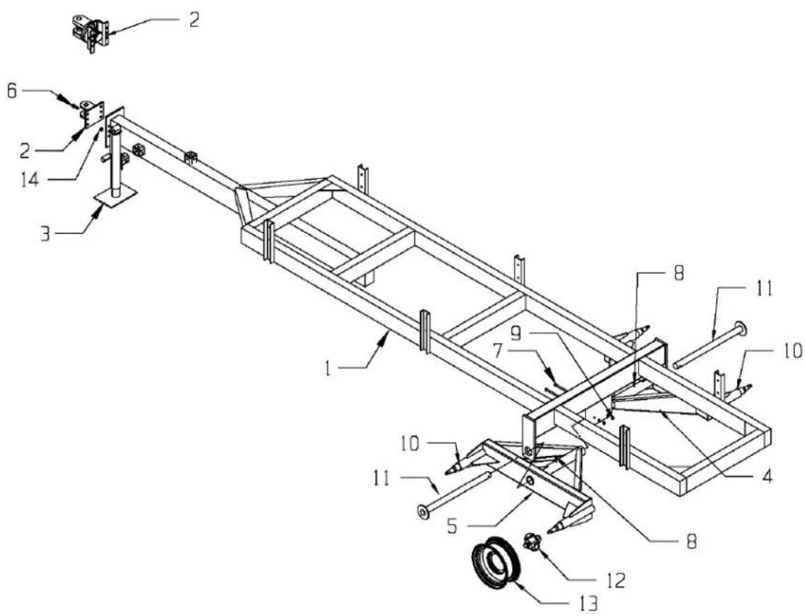
text_image
Technical diagram of a mechanical assembly with numbered components for identificationMODELS XT1600 & XT1600L FRAME & O-BEAM
| KEY PART NO. DESCRIPTION QTY. | |||
| 1 75-1600 Trailer Frame | Assembly-XT1600 1 | ||
| 75-1600-L Trailer Frame Assembly-XT1600L 1 | |||
| 2 75-0074 Bolt On Hitch | 1 | ||
| 75-2005 Optional Swivel Hitch 1 | |||
| 3 956-3803 Jack 1 | |||
| 4 | 75-1601 | Right O-Beam Assembly Less Hubs | 1 |
| 75-1603 Right O-Beam Assembly W/Hubs 1 | |||
| 5 | 75-1602 | Left O-Beam Assembly Less Hubs | 1 |
| 75-1604 | Left O-Beam Assembly W/Hubs | 1 | |
| 6 | 851-6311-2Z | 5/8-11x2" Machine Bolt Grade 5 (Standard Hitch Only) | 6 |
| 881-6314-2Z | 5/8-14x2" Machine Bolt Grade 8 (Swivel Hitch Only) | 6 | |
| 7 | 881-5013-5Z | 1/2-13x5" Machine Bolt Grade 8 (Prior to Serial #0816206) | 2 |
| 881-6311-5.5Z | 5/8-11x5-1/2" Machine Bolt Grade 8 (Serial #0816206 & Later) | 2 | |
| 8 | 30-0007 | 1/8" NPTx45 Degree Zerk | 2 |
| 9 | 815-5013-Z | 1/2-13 Nylon Insert Locknut (Prior to Serial #0816206) | 2 |
| 815-6311-Z | 5/8-11 Nylon Insert Locknut (Serial #0816206 & Later) | 2 | |
| 10 | 75-0107 | 3x18-1/2" Straight Spindle | 4 |
| 11 | 75-3005-1 | Pivot Shaft Weldment | 2 |
| 12 | 75-0207 | Hub (See Page 20) | 4 |
| 13 | 75-0255 15x10" Wheel AR | ||
| 75-0253-HD | 16.1x11" Wheel | AR | |
| 75-0262-HD | 16.1x14" Wheel | AR | |
| 75-0268-HD | 22.5x8.25" Wheel | AR | |
| 75-0260 22.5x13.5" Wheel AR | |||
| 14 | 815-6311-Z | 5/8-11 Nylon Insert Locknut | 6 |
| 884-6318 | 5/8-18 Top Locknut Grade 8 | 6 | |
MODEL XT2200, XT2200L & XT2200XL FRAME
PRIOR TO SERIAL #0822201
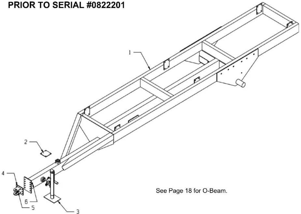
text_image
PRIOR TO SERIAL #0822201 See Page 18 for O-Beam.See Page 18 for O-Beam.
| KEY PART NO. DESCRIPTION QTY. | |||
| 1 | 75-2000 | Trailer Frame Assembly - XT2200 | 1 |
| 75-2000-L | Trailer Frame Assembly - XT2200L | 1 | |
| 75-2000-XL | Trailer Frame Assembly - XT2200XL | 1 | |
| 2 | 75-2020 | Plate, Brake Actuator Mount, Opt | 1 |
| 3 956-3803 Jack 1 | |||
| 4 75-0074 Hitch Plate Assembly 1 | |||
| 5 | 851-6311-2Z | 5/8-11 x 2" Machine Bolt Grade 5 | 6 |
| 6 | 815-6311-Z | 5/8-11 Nylon Insert Locknut | 6 |
MODEL XT2200, XT2200L & XT2200XL FRAME
SERIAL #0822201 AND LATER
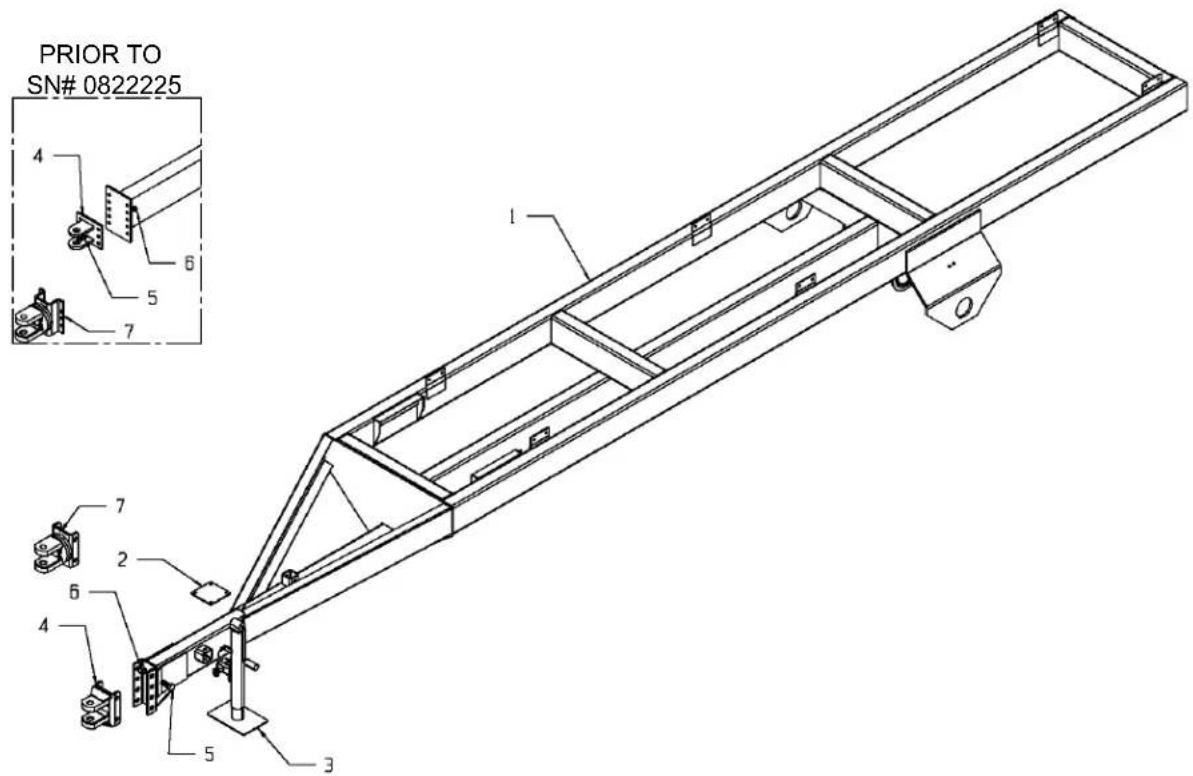
text_image
PRIOR TO SN# 0822225 4 6 5 7 1 7 2 6 4 5 3| KEY PART NO. DESCRIPTION QTY. | |||
| 1 75-2200 Trailer Frame Assembly-XT2200 1 | |||
| 2 | 75-2020 | Plate, Brake Actuator Mount (Optional) | 1 |
| 3 956-3803 Jack 1 | |||
| 4 | 75-0074 | Hitch Plate Assy, (Prior to Serial #0822225) | 1 |
| 75-0076 | Hitch Plate Assy. (Serial #0822225 & Later) | 1 | |
| 5 | 851-6311-2Z | 5/8-11x2" Machine Bolt Grade 5 (Prior to Serial #0822225) | 6 |
| 881-1014-2.5Z | 1x2-1/2" Machine Bolt Grade 8 (Serial #0822225 & Later) | 4 | |
| 6 | 815-6311-Z | 5/8-11 Nylon Insert Locknut (Prior to Serial #0822225) | 6 |
| 884-1014-Z | 1-14 Top Locknut (Serial #0822225 & Later) | 4 | |
| 7 | 75-2005 | Optional Swivel Hitch (Prior to Serial #0822225) | 1 |
| 901-3757 | Swivel Hitch Assy. (Serial #0822225 & Later) | 1 | |
MODEL XT2200, XT2200L & XT2000XL O-BEAM

text_image
PRIOR TO SERIAL #0822201| KEY PART NO. DESCRIPTION QTY | |||
| 1 75-0111 3-1/2" Spindle Assembly 4 | |||
| 2 | 75-2000-20 | XT2200 O-Beam Center Pivot Shaft Welded Assembly | 2 |
| 3 901-3867-2 Tandem Locking Collar 2 | |||
| 4 901-3864-2 Pivot Shaft Nylon Bushing 2 | |||
| 5 | 30-0006 | Zerk 1/8" NPT x 90 Degrees | 2 |
| 6 | 30-0006 | Zerk 1/8" NPT x 90 Degrees | 2 |
| 7 30-0009 1/8" NPT Coupler 2 | |||
| 8 30-0008 1/8" NPT Nipple 2 | |||
| 9 | 933-3626 | Copper Tube Grease Line 31" (Includes zerks, fittings) | 2 |
| 10 | 30-0002 | 1/8" NPT Straight Zerk | 2 |
| 11 | 75-2010 | Right O-Beam w/o Hubs | 1 |
| 75-2010-B | Brake Right O-Beam w/o Hubs | 1 | |
| 75-2012 | Right O-Beam Complete w/Hubs | 1 | |
| 75-2012-B | Brake Right O-Beam Complete w/Hubs | 1 | |
| 12 | 75-2013 | Left O-Beam Complete w/Hubs | 1 |
| 75-0213-B | Brake Left O-Beam Complete w/Hubs | 1 | |
| 75-2011 | Left O-Beam w/o Hubs | 1 | |
| 75-0211-B | Brake Left O-Beam w/o Hubs | 1 | |
| 13 | 881-5013-6.5 | HHCS, 1⁄2-13 x 6-1/2" Gr. 8 | 2 |
| 14 | 814-5013-Z | 1⁄2-13 Center Locknut | 2 |
| 15 | 75-0211 | Hub (See Page 21) | 4 |
| 16 | 75-0270 | Wheel Rim SW18C x 16.1 x 10 Hole For 21.5 x 16.1 Tire | 4 |
| 75-0269 | Wheel Rim 12.25 x 22.5 x 10 Hole For Used 425/65/R22.5 Tire | 4 | |
MODEL XT2200, XT2200L & XT2000XL AXLE & WHEELS
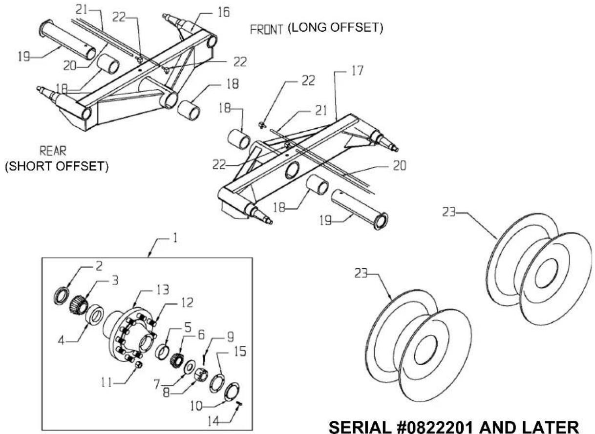
text_image
FRONT (LONG OFFSET) REAR (SHORT OFFSET) SERIAL #0822201 AND LATER| KEY PART NO. DESCRIPTION QTY | |||
| 1 75-0211 Hub Assembly Complete 15,000# 4 | |||
| 2 75-0211-2 Seal 1 | |||
| 3 75-0211-3 Bearing Cone 1 | |||
| 4 75-0211-4 Bearing Cup 1 | |||
| 5 75-0208-5 Bearing Cup 1 | |||
| 6 75-0208-6 Bearing Cone 1 | |||
| 7 75-0208-7 Washer 1 | |||
| 8 75-0208-8 Nut 1 | |||
| 9 75-0208-9 Cotter Pin 1 | |||
| 10 75-0208-10 Hub Cap | 1 | ||
| 11 | 75-0208-11 | Lug Nut - Flanged | 10 |
| 12 75-0208-12 Stud Bolt | 10 | ||
| 13 | 75-0211-1 | Hub Only w/Races & Studs | 1 |
| 14 | 75-0208-13 | Hub Cap Bolt | 4 |
| 15 | 75-0208-14 | Hub Cap Gasket | 1 |
| 16 | 901-8720-11-1 | LH Tandem Wing Assembly, Less Hubs | 1 |
| 17 | 901-8720-10-1 | RH Tandem Wing Assembly, Less Hubs | 1 |
| 18 | 901-8720-10-1-4 | Nylon Pivot Sleeve | 4 |
| 19 | 901-8720-15 | O-Beam Pivot Assembly | 2 |
| 20 | 955-3761 | 3/16x10" Grease Hose | 2 |
| 21 | 955-3762 | 3/16X16" Grease Hose | 2 |
| 22 | 30-0020 | 1/8" NPT Street L | 4 |
| 23 | 75-0273 | 22.5x13 Wheel 0" Offset 425 Used Truck Tire | 4 |
| 75-0270 | 18X16.1 Wheel 21.5L Implement Tire | 4 | |
HUB FOR MODELS XT1600 & XT1600L
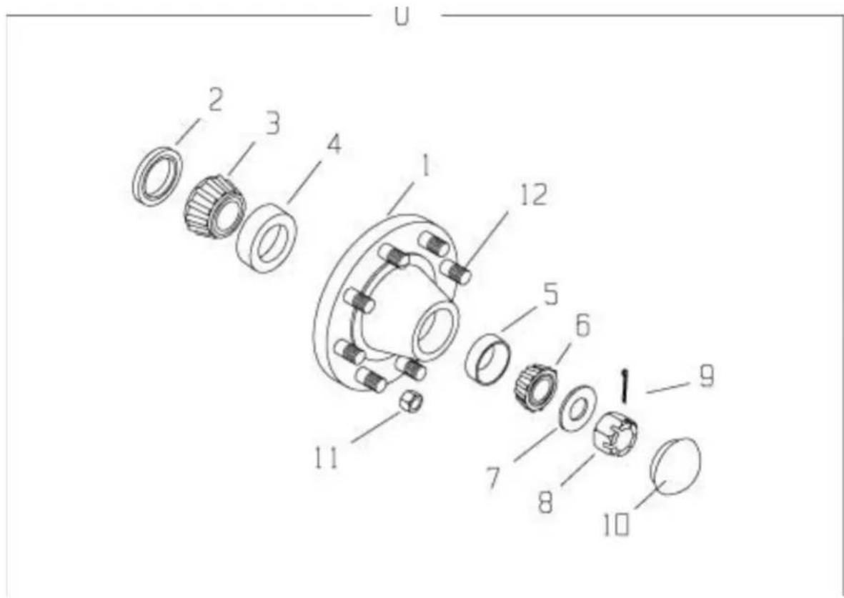
text_image
U 1 2 3 4 1 12 5 6 1 9 7 8 10 11| KEY | PART NO. | DESCRIPTION | QTY | |
| 0 | 75-0207 | Hub , Complete | Assembly 4 | |
| 1 | 75-0207-1 | Hub w/Races | 1 | |
| 2 | 75-0207-2 | Grease Seal 1 | ||
| 3 | 75-0207-3 | Inner Wheel Bearing | 1 | |
| 4 | 75-0207-4 | Inner Wheel Race | 1 | |
| 5 | 75-0202-4 | Outer Wheel Race | 1 | |
| 6 | 75-0202-3 | Outer Wheel Bearing | 1 | |
| 7 | 75-0205-7 | Washer 1 | ||
| 8 | 75-0205-8 | Nut 1 | ||
| 9 | 75-0205-9 | Cotter Pin | 1 | |
| 10 | 75-0205-10 | Cap | 1 | |
| 11 | 75-0205-11 | Lug Nut | 8 | |
| 12 | 75-0207-12 | Stud Bolt | 8 | |
HUB FOR MODELS XT2200, XT2200L & XT2000XL
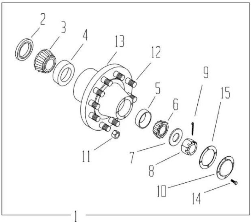
text_image
Exploded view diagram of a mechanical assembly with numbered parts for identification| KEY PART NO. DESCRIPTION QTY | |||
| 1 75-0211 Hub Assembly Complete 15,000# 4 | |||
| 2 75-0211-2 Seal 1 | |||
| 3 75-0211-3 Bearing Cone 1 | |||
| 4 75-0211-4 Bearing Cup 1 | |||
| 5 75-0208-5 Bearing Cup 1 | |||
| 6 75-0208-6 Bearing Cone 1 | |||
| 7 75-0208-7 Washer 1 | |||
| 8 75-0208-8 Nut 1 | |||
| 9 75-0208-9 Cotter Pin 1 | |||
| 10 75-0208-10 Hub Cap | 1 | ||
| 11 | 75-0208-11 | Lug Nut - Flanged | 1 |
| 12 75-0208-12 Stud Bolt | 1 | ||
| 13 | 75-0211-1 | Hub Only w/Races & Studs | 1 |
| 14 | 75-0208-13 | Hub Cap Bolt | 1 |
| 15 | 75-0208-14 | Hub Cap Gasket | 1 |
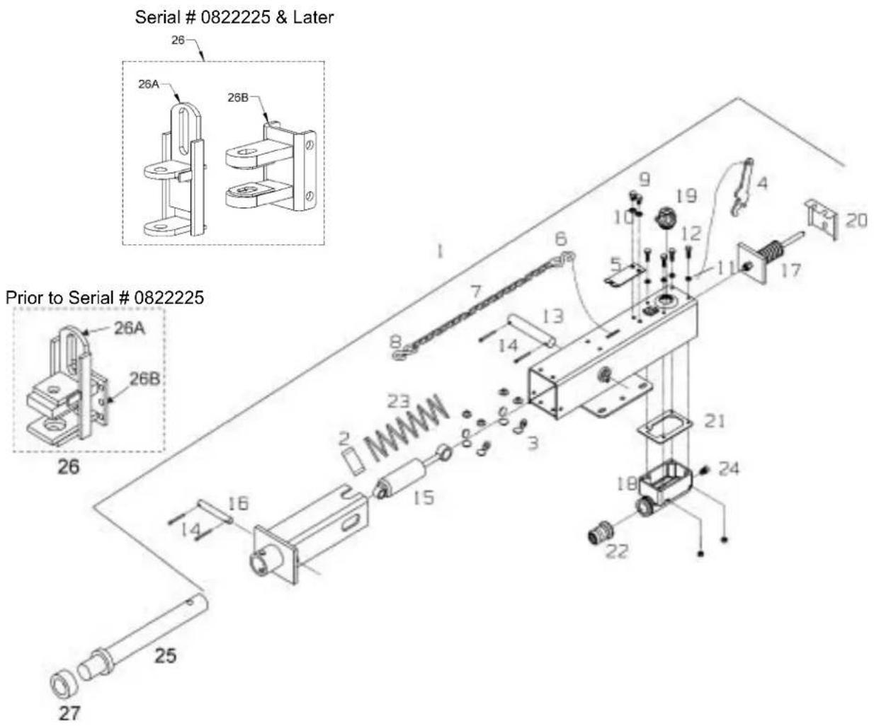
XT2200 OPTIONAL BRAKE PACKAGE
(1 OF 2)
text_image
Serial # 0822225 & Later Prior to Serial # 0822225 26 26A 26B 26 1 7 6 8 13 14 9 10 19 12 5 4 11 17 20 23 2 15 3 16 14 21 24 18 22 25 27XT2200 SERIES OPTIONAL BRAKE PACKAGE (1 OF 2)
| KEY PART # DESCRIPTION QTY. | |||
| 1 | 57-0032 | XT2200 Trailer Optional Brake Actuator | 1 |
| 2 57-00 | 29-1 Spring Spacer | 1 | |
| 3 57-00 | 29-2 Nylon Slide Bearing Button | 12 | |
| 4 *57-00 | 29-3 Safety Break-Away Lever | 1 | |
| 5 *57-00 | 29-4 Safety Break-Away Lock | 1 | |
| 6 57-00 | 09-2 S-Hook (Heavy Stationary) | 1 | |
| 7 57-00 | 30 Safety Break-Away Chain 96" | 1 | |
| 8 33-00 | 32-1 S-Hook (Break-Away) | 1 | |
| 9 | 57-0029-5 | 5/16-18 x 5/8" Machine Bolt Grade 5 | 2 |
| 10 | 57-0029-6 | 5/16" External Tooth Lock-Washer | 2 |
| 11 | 822-0025-Z | 14 " Split Lock-Washer | 4 |
| 12 | 851-2520-.75Z | 14 -20 x 34 " Machine Bolt Grade 5 | 4 |
| 13 | 57-0029-7 | Damper Pin 7/8 x 4-15/16" | 1 |
| 14 | 57-0029-8 | 5/32 x 1-1/4" Cotter Pin | 4 |
| 15 | 57-0029-9 Damper | Shock | 1 |
| 16 | 57-0029-10 | Damper Pin 5/8 x 3-3/4" | 1 |
| 17 | 57-0029-11 | Push Rod Assembly | 1 |
| 18 | 57-0029-12 | Master Cylinder Assembly | 1 |
| 19 | 57-0029-13 | Actuator Filler Cap W/Diaphragm & O-Ring | 1 |
| 20 | 57-0029-14 | Actuator Rear Cover | 1 |
| 21 | 57-0029-15 | Master Cylinder Gasket | 1 |
| 22 | 57-0029-16 | Master Cylinder Protective Boot | 1 |
| 23 | 29-0009 Spring | 1 | |
| 24 | 57-0029-17 | Inverted Flare Fitting - Full Flow | 1 |
| 25 | 75-2021 | XT2200 Actuator Push Shaft Assembly (Prior to Serial # 0822225) | 1 |
| 75-2021-L | XT2200 Actuator Push Shaft Assembly (Serial # 0822225 & Later) | 1 | |
| 26 | 75-2022 | XT2200 Brake Hitch Plate Weldment (Prior to Serial # 0822225) | 1 |
| 75-0077 | XT2200 Brake Hitch Plate Weldment (Serial # 0822225 & Later) | 1 | |
| 26A | 75-2022-9 | Outer Brake Hitch Plate (Prior to Serial #0822225) | 1 |
| 75-0077-2 | Outer Brake Hitch Plate (Serial #0822225 & Later) | 1 | |
| 26B | 75-2022-8 | Brake Hitch Plate (Prior to Serial #0822225) | 1 |
| 75-0077-1 | Brake Hitch Plate (Serial #0822225 & Later) | 1 | |
| 27 | 921-0005 | 1-1/2" Set Collar | 1 |
| THE FOLLOWING PARTS ARE NOT ILLUSTRATED | |||
| 57-0029-18 | 1-1/4" Master Cylinder Repair Kit (Not Shown) | 1 | |
| 57-0029-19 | Lever Replacement Kit (Includes Items W/*) | 1 | |
| 32-0024 | 9/32" Brake line Loom Clamp | AR | |
| 57-0010 18"Hydraulic Brake Hose | AR | ||
| 57-0013 Frame Tee W/Clip | AR | ||
| 57-0014-2 Brake Line Union | AR | ||
| 57-0020 90" Brake Line | AR | ||
| 65-0006-5 Nylon Tie Straps | AR | ||
| 57-0017 Frame Tee Plug | AR | ||
| 75-0211-B | XT2200 10 Bolt Brake Hub | AR | |
| 813-5020-Z | 12 -20 Nut Fine Thread Zinc | AR | |
| 822-0050-Z | 12 " Split Lock-Washer | AR | |
| 825-25-1Z | 14 x 1" Self Tapping Screw | AR | |
| 851-5020-1Z | 12 -20 x 1" UNF Grade 5 Machine Bolt Zinc | AR | |
| 806-0050-Z | 12 " Internal Tooth Lock-Washer Zinc | AR | |
| 33-1003 Rubber Grommet | AR | ||
| 57-0027 | 48" Brake Line Assembly | AR | |
| 57-0033 1/8" NPT Plug | AR | ||
| 57-0041 Cluster Mount Bracket | AR | ||
| 57-0036 224" Brake Line | AR | ||
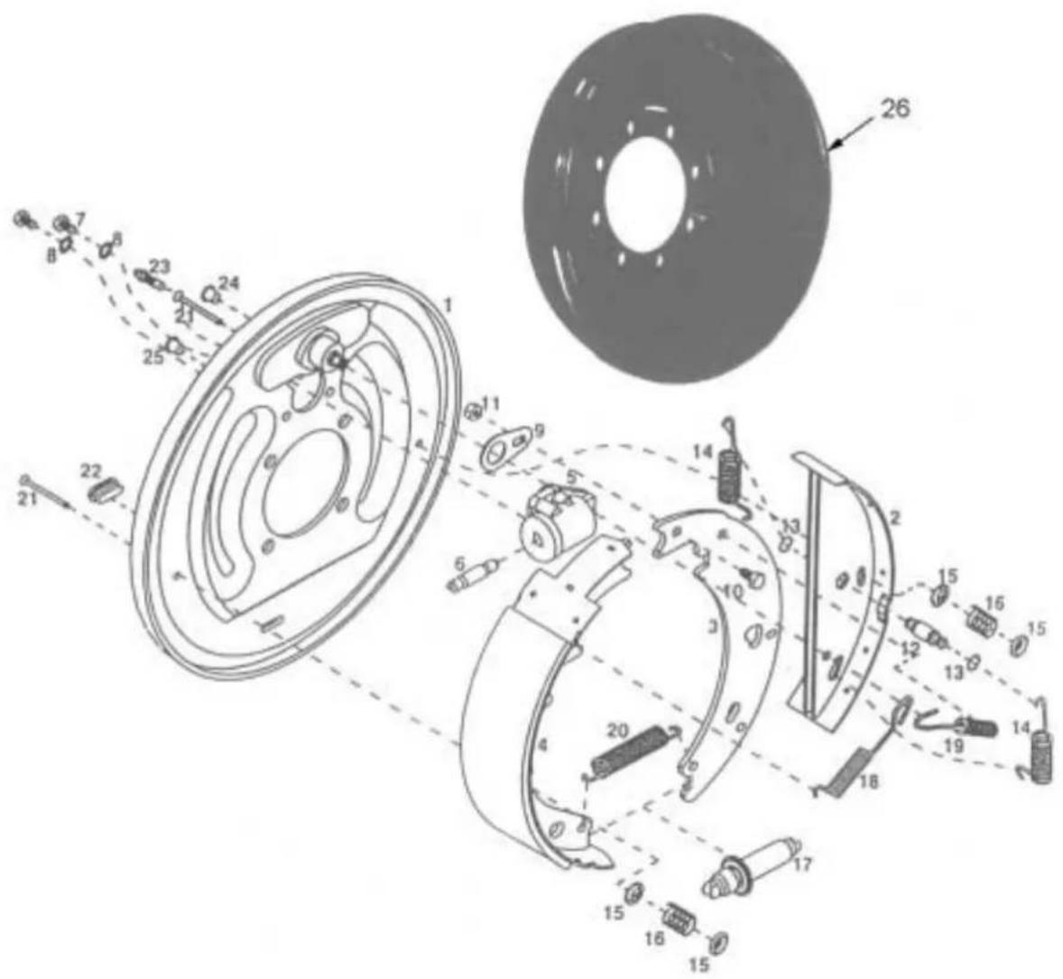
XT2200 OPTIONAL BRAKE PACKAGE (2 OF 2)
text_image
Technical diagram of a mechanical assembly with numbered components and exploded view, likely for assembly or manufacturing purposes.XT2200 SERIES OPTIONAL BRAKE PACKAGE (2 OF 2)
| KEY PART # DESCRIPTION QTY. | |||
| 57-0002 | 13" R.H. Free Backing Brake Assembly | 1 | |
| 57-0003 | 13" L.H. Free Backing Brake Assembly | 1 | |
| 1 57-0002-2 Back Plate Assembly 1 | |||
| 2 57-0002-3 Brake Shoe Assembly 1 | |||
| 3 57-0002-4 Shoe Lever 1 | |||
| 4 57-0002-5 Shoe Assembly 1 | |||
| 5 57-0003-1 Wheel Cylinder assembly Left 1 | |||
| 57-0002-1 | Wheel Cylinder assembly Right (Not Shown) | 1 | |
| 6 57-0002-6 Push Rod 1 | |||
| 7 | 57-0002-7 | 5/16-18 UNC X 1⁄2" H.H.M.B. | 2 |
| 8 | 57-0002-8 | 5/16" External Tooth Lockwasher | 2 |
| 9 57-0002-9 Travel Link 1 | |||
| 10 | 57-0002-10 | 5/16-18 UNC X 5/8" H.H.M.B. | 1 |
| 11 | 57-0002-11 | 5/16-18 UNC Bi-Way Locknut | 1 |
| 12 | 57-0002-12 | Double Pin shoe | 1 |
| 13 | 57-0002-13 | Retaining Ring | 1 |
| 14 | 57-0002-14 | Spring Shoe | 2 |
| 15 | 57-0002-15 | Cup Shoe Hold Down | 4 |
| 16 | 57-0002-16 | Spring-Shoe Hold Down | 2 |
| 17 | 57-0002-17 | Adjusting Screw Assembly | 1 |
| 18 | 57-0002-18 | Spring-Shoe | 1 |
| 19 | 57-0002-19 | Spring Lever | 1 |
| 20 | 57-0002-20 | Spring-Adjusting screw | 1 |
| 21 | 57-0002-21 | #1 Shoe Hold Down Pin | 2 |
| 22 | 57-0002-22 | Cover Plate-Adjusting Hole | 1 |
| 23 | 57-0002-23 | Replacement Bleeder | 1 |
| 24 | 57-0002-24 | Plastic Plug | 1 |
| 25 | 57-0002-25 | Plastic Plug | 1 |
| 57-0002-26 | Wheel Cylinder Repair Kit (Not Shown) Includes Spring, Cup & Boot | 1 | |
| 26 | 57-0040 | 13" Brake Drum | AR |
| 27 | 57-0007 | Brake Mount Donut (Not Shown) | AR |
TRAILER AND BOX MOUNTING SPECIFICATION SHEET
| TRAILERS XT1600 XT1600L XT2200 XT2200L XT2200XL | ||||
| BOXES | ||||
| 4516 OK NA NA NA NA | ||||
| 4518 NA OK NA NA NA | ||||
| 4616 OK NA NA NA NA | ||||
| 4618 NA OK NA NA NA | ||||
| 4620 NA OK OK NA NA | ||||
| 4622 NA NA OK OK NA | ||||
| 4116 OK NA NA NA NA | ||||
| 4118 OK NA NA NA NA | ||||
| 4120 NA OK OK NA NA | ||||
| 4122 NA NA OK NA NA | ||||
| 4216 OK NA NA NA NA | ||||
| 4218 NA OK NA NA NA | ||||
| 4220 NA OK OK NA NA | ||||
| 4222 NA NA OK OK NA | ||||
| 6218 NA OK NA NA NA | ||||
| 6220 NA NA OK NA NA | ||||
| 6222 NA NA NA OK NA | ||||
| 6224 NA NA NA NA OK | ||||
| 3514 OK NA NA NA NA | ||||
| 3516 OK NA NA NA NA | ||||
| 3518 NA OK NA NA NA | ||||
| 3516-FB OK NA NA NA NA | ||||
| 3518-FB NA OK NA NA NA | ||||
| 3116 OK NA NA NA NA | ||||
| 3118 OK NA NA NA NA | ||||
| 3120 NA OK OK NA NA | ||||
| 3216 OK NA NA NA NA | ||||
| 3218 NA OK NA NA NA | ||||
| 3220 NA OK OK NA NA | ||||
| 8118 NA NA OK NA NA | ||||
| 8120 NA NA OK NA NA | ||||
| 8122 NA NA OK OK NA | ||||
| 8124 NA NA NA OK OK | ||||
| 8126 NA NA NA NA NA | ||||
| 9122 NA NA OK OK NA | ||||
| 9124 NA NA NA OK OK | ||||
| 9126 NA NA NA NA NA | ||||
| 9128 NA NA NA NA NA | ||||
| 9130 NA NA NA NA NA | ||||
| NA-Not Available | ||||
| LOADED BOXES MUST NOT EXCEED CARRYING CAPACITY OF TRAILERS | ||||
| PTO UNLOAD BOXES- 50" - 64" HITCH PIN TO IMPLEMENT PTO KNUCKLE | ||||
| HYDRAULIC UNLOAD BOXES- 50" - 64" HITCH PIN TO FRONT OF BOX/UNIT | ||||
| 81/9100 BOXES ON XT2000 SERIES TRAILERS- 12" OVER HANG OF BOX ON THE FRONT OF THE TRAILER | ||||
SPECIFICATIONS
| Model M1100 | XT1600 XT1600L | XT2200 XT2200L | XT2200XL | |||
| Style Tandem | Tandem Tandem | Long | Tandem Tandem Long | Tandem Long | ||
| Capacity | 22,000 lbs. | 32,000 lbs. | 32,000 lbs. | 40,000 lbs. | 40,000 lbs. | |
| Tread Width 76" | 82" | 82" | 80" | |||
| Spindle Size 2" | 3" | 3" | 3.5" | |||
| Heavy Duty Hubs | 6-Bolt 4570# at 10 MPH | 8-Bolt 8000# at 10 MPH | 8-Bolt 8000# at 10 MPH | 10-Bolt 15,000# at 10 MPH | 10-Bolt 15,000# at 10 MPH | |
| Frame Design | 8" Channel 3x6x1/4" Tubing | 3x6x1/4" Tubing | 4x8x1/4" Tubing | 4x8x1/4" Tubing | ||
| Weight | 1,500# w/12.5Lx15 | 3,145# w/riser 425/65x22.5 | 3,240# w/riser 425/65x22.5 | 3,680# w/riser w/21.5x16.1 | 3,810# w/riser w/21.5x16.1 | |
| Overall Length | 20' 9-1/2" | 20' 8-1/2" | 24' | 25' 2-1/2" | 27' 2-1/2" | |
| Bed Length | 13' 8-1/2" | 13' 7" | 16' 10-1/2" | 18' | 20' | |
| Overall Width | 89" w/12.5Lx15 | 100-1/2" w/16.5Lx16.1 98-1/4" w/425/65x22 .5 | 100-1/2" w/16.5Lx16.1 98-1/4" w/425/65x22 .5 | 102-1/2" w/21.5x16.1 98-1/2" w/425/65x22 .5 | 102-1/2" w/21.5x16.1 98-1/2" w/425/65x22 .5 | |
| Bed Width | 42" 42" | 42" | 42" | |||
| Stake Spacing | 42" 42" | 42" | or | 42" or 33-1/2" (Opt or std) | ||
| Bed Height | 30" w/12.5Lx15 | 32" w/14Lx16.1 w/o riser 38-1/2" w/425/65x22 .5 w/riser | 32" w/14Lx16.1 w/o riser 38-1/2" w/425/65x22 .5 w/riser | 44" w/21.5x16.1 43-1/4" w/425/65x22 .5 | 44" w/21.5x16.1 43-1/4" w/425/65x22 .5 | |
| Adj. Clevis Hitch | Standard Standard Standard Standard Standard | |||||
| Options | ||||||
| Surge Brakes | N/A | N/A | N/A | Optional | Optional | Optional |
| Swivel Clevis Hitch | N/A | N/A | N/A | Optional | Optional | Optional |
| Riser Package 4" | N/A | Optional Req. for 19Lx16.1 or 425/65x22.5 | Optional Req. for 19Lx16.1 or 425/65x22.5 | N/A | N/A | N/A |
| Various Tires Sizes | See Dealer | See Dealer | See Dealer | See Dealer | See Dealer | See Dealer |