MS-890 - Barcode Reader Microscan - Free user manual and instructions
Find the device manual for free MS-890 Microscan in PDF.


User questions about MS-890 Microscan
0 question about this device. Answer the ones you know or ask your own.
Ask a new question about this device
Download the instructions for your Barcode Reader in PDF format for free! Find your manual MS-890 - Microscan and take your electronic device back in hand. On this page are published all the documents necessary for the use of your device. MS-890 by Microscan.
USER MANUAL MS-890 Microscan
MS-890 Industrial Automation Scanner User Manual
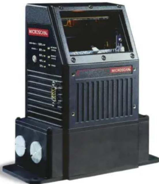
natural_image
Black microscan device with ventilation slots and control panel (no visible text or symbols on body)Copyright and Disclaimer
Copyright ©2015
Microscan Systems, Inc.
Tel: +1.425.226.5700 / 800.762.1149
Fax: +1.425.226.8250
All rights reserved. The information contained herein is proprietary and is provided solely for the purpose of allowing customers to operate and/or service Microscan manufactured equipment and is not to be released, reproduced, or used for any other purpose without written permission of Microscan.
Throughout this manual, trademarked names might be used. We state herein that we are using the names to the benefit of the trademark owner, with no intention of infringement.
Disclaimer
The information and specifications described in this manual are subject to change without notice.
Latest Manual Version
For the latest version of this manual, see the Download Center on our web site at: www.microscan.com.
Technical Support
For technical support, e-mail: helpdesk@microscan.com.
Warranty
For current warranty information, see: www.microscan.com/warranty.
Microscan Systems, Inc.
United States Corporate Headquarters
+1.425.226.5700 / 800.762.1149
United States Northeast Technology Center
+1.603.598.8400 / 800.468.9503
European Headquarters
+31.172.423360
Asia Pacific Headquarters
+65.6846.1214
Table of Contents
Chapter 1 Quick Start
Step 1 Check Required Hardware....1-2
Step 2 Connect the System.... 1-3
Step 3 Position Scanner and Symbol 1-5
Step 4 Install ESP.... 1-6
Step 5 Select Model ......1-7
Step 6 Autoconnect ...... 1-8
Step 7 Receive Settings....1-9
Step 8 Calibrate.... 1-10
Step 9 Test Read Rate 1-11
Step 10 Configure the Scanner in ESP .... 1-12
Step 11 Save Configuration in ESP....1-13
Chapter 2 Using ESP
EZ Mode 2-2
Application Mode 2-3
Menu Toolbar 2-4
Autoconnect.... 2-12
View.... 2-14
Navigating in ESP 2-15
Send/Receive Options.... 2-16
Chapter 3 Communications
Communications by ESP.... 3-2
Communications Serial Commands 3-2
RS-232/422 Host Port 3-3
Host Port Parameters 3-4
Host Protocol 3-5
Poll Address 3-7
ACK / NAK Options 3-8
Polling Mode Options 3-9
Auxiliary Port Protocol 3-10
Daisy Chain Autoconfigure 3-19
Daisy Chain Scanner ID 3-20
Auxiliary / Configuration Port System Data 3-21
Preamble 3-22
Postamble.... 3-23
LRC Status 3-24
Intercharacter Delay 3-25
Response Timeout 3-26
Chapter 4 Read Cycle
Read Cycle by ESP 4-2
Read Cycle Serial Commands 4-2
Multisymbol.... 4-3
Table of Contents
Trigger 4-5
External Trigger State 4-11
Serial Trigger.... 4-12
Start Character (Non-Delimited) 4-13
Stop Character (Non-Delimited) 4-13
End of Read Cycle 4-14
Good Decode Reads.... 4-17
Gain Settings.... 4-18
Focus....4-19
Scan Speed.... 4-20
Automatic Gain Control (AGC) Settings 4-21
Maximum Element 4-22
Tracking Adjustment.... 4-23
Chapter 5 Symbologies
Symbologies by ESP.... 5-2
Symbologies Serial Commands 5-2
Code 39....5-3
Code 128 / EAN-128 5-6
Interleaved 2 of 5.... 5-10
Codabar....5-13
UPC/EAN 5-16
Code 93....5-19
Pharmacode 5-20
PDF417 5-22
Narrow Margins / Symbology ID....5-24
Background Color.... 5-26
Autodiscriminate....5-27
Chapter 6 I/O Parameters
I/O Parameters by ESP 6-2
I/O Parameters Serial Commands 6-3
Symbol Data Output 6-4
No Read Message.... 6-6
Bad Symbol Message 6-7
No Symbol Message 6-7
Read Duration Output 6-8
Output Indicators 6-9
Beeper....6-12
Serial Verification.... 6-13
EZ Button 6-15
EZ Button Modes.... 6-17
Input 1 6-19
Configurable Output 1 6-20
Trend Analysis Output 1 6-24
Diagnostics Output 1....6-27
Introduction
Configurable Output 2 6-28
Trend Analysis Output 2 6-28
Diagnostics Output 2 6-28
Configurable Output 3 6-29
Trend Analysis Output 3 6-29
Diagnostics Output 3 6-29
Database Identifier Output....6-30
Quality Output.... 6-31
Chapter 7 Matchcode
Matchcode by ESP 7-2
Matchcode Serial Commands 7-2
Overview of Matchcode 7-3
Using Master Symbols....7-4
Matchcode Type 7-5
Sequence Step 7-10
New Master Pin 7-11
Match Replace....7-12
Mismatch Replace 7-13
Chapter 8 Diagnostics
Diagnostics by ESP 8-2
Diagnostics Serial Commands 8-2
Counts 8-3
Hours Since Last Reset 8-4
Warning Messages....8-5
Laser Current Warning 8-7
Present Operating Temperature (Deg. C) 8-8
High Temperature Threshold....8-9
Low Temperature Threshold 8-10
Lifetime Hours 8-11
Service Message 8-12
Chapter 9 Calibration
Calibration Serial Commands....9-2
Calibration Steps 9-3
Calibration Routine 9-4
Calibration Results 9-5
Configuration Database....9-6
Optoelectric Control....9-8
Advanced Calibration Features 9-14
Calibration by Embedded Menu 9-17
Chapter 10 Raster/Laser
Raster/Laser Setup by ESP 10-2
Raster/Laser Serial Commands 10-2
Raster Setup.... 10-3
Laser Framing 10-7
Table of Contents
Raster/Laser by Embedded Menu.... 10-9
Chapter 11 Terminal
Terminal Window.... 11-2
Find 11-3
Send 11-4
Macros.... 11-5
Terminal Window Menus.... 11-6
Chapter 12 Utilities
Serial Utility Commands 12-2
Read Rate 12-4
Counters.... 12-6
Device Control.... 12-8
Differences from Default.... 12-10
Master Database 12-11
Digital Bar Code 12-16
Firmware 12-17
Autodiscriminate.... 12-19
Scanner Status Requests.... 12-20
Chapter 13 Output Format
Output Format Serial Commands.... 13-2
Output Format Status 13-3
Format Assign 13-4
Format Extract.... 13-5
Format Insert 13-7
Output Filter Configuration 13-9
Number of Filters.... 13-14
Chapter 14 Wiring Box
Wiring Box Description 14-2
Installation Steps 14-3
Wiring Box Ports.... 14-5
Wiring Box PCB with Connectors.... 14-8
Mounting Plate 14-9
Appendices
Appendix A General Specifications ....A-2
Appendix B Electrical Specifications ......A-4
Appendix C Serial Configuration Commands....A-9
Appendix D ASCII Table ......A-15
Appendix E Embedded Menus....A-17
Appendix F Defaulting / Saving / Initializing ......A-18
Appendix G Position Scanner and Symbol ......A-21
Appendix H Object Detector....A-22
Appendix I Bar Code Configuration....A-23
Appendix J Test Read Rate ......A-25
Appendix K Formulas for Number of Decodes....A-27
Introduction
Appendix L Operational Tips ......A-32
Appendix M Interface Standards ......A-33
Appendix N Multidrop Communications ......A-34
Appendix O Glossary of Terms ......A-39
About the MS-890 Industrial Automation Scanner
The key features of the MS-890 Industrial Automation Scanner are:
- Wide angle sweeping raster
- EZ Button setup
- Configurable with ESP Software
• 400 to 1,000 decodes per second - IP65 rated enclosure
- Optional wiring box
• LED performance indicators
- Long-distance read range (10" to 120" (254 mm to 3,048 mm))
About This Manual
This manual provides complete information on setting up, installing, and configuring the MS-890 Industrial Automation Scanner. The chapters follow the ESP menus, which are presented in the order in which a scanner might be set up and made ready for industrial operation. Host serial commands are presented side-by-side with ESP.
Highlighting
Serial commands, highlighted command fields, and default command settings are highlighted in rust bold. Cross-references and web links are highlighted in blue bold. References to ESP, its toolbar headings (Communications, Read Cycle, Symbologies, etc.), menu topics, and other points of emphasis, are highlighted in Bold Initial Caps.
Host Communications
There are four ways to configure and test the MS-890 Industrial Automation Scanner:
- EZ Button.
- Microscan's Windows-based ESP (Easy Setup Program), which offers point-and-click ease of use and visual responses to user adjustments.
- Serial commands, such as
- The tree controls and graphic interfaces in ESP's App Mode.
Statement of Agency Compliance

The MS-890 Industrial Automation Scanner has been tested for compliance with FCC (Federal Communications Commission) regulations and has been found to conform to all applicable FCC Rules and Regulations.
To comply with FCC RF exposure compliance requirements, this device must not be co-located or operate in conjunction with any other antenna or transmitter.
Changes or modifications not expressly approved by the party responsible for compliance could void the user's authority to operate the equipment.

The MS-890 Industrial Automation Scanner has been tested for compliance with CE (Conformité Européenne) standards and guidelines, and has been found to conform to applicable CE standards, specifically EN61000-6-3:2001: for Class A products; EN61000-3-2:2000+A2:2005; EN61000-3-3:1995+A1:2001; EN61000-6-2: Immunity.
The MS-890 Industrial Automation Scanner has been tested by an independent electromagnetic compatibility laboratory in accordance with the applicable specifications and instructions.
Approvals
This equipment is in compliance or approved by the following organizations:
• FCC (Federal Communications Commission)
• CDRH (Center for Devices and Radiological Health)
• CE (Conformité Européenne)
- UL/cUL (Underwriters Laboratories, Inc.; UL Canada)
• BSMI (Bureau of Standards, Metrology and Inspection)
Warning and Caution Summary
This equipment has been tested and found to comply with the limits for a Class A digital device, pursuant to part 15 of the FCC Rules. These limits are designed to provide reasonable protection against harmful interference in a residential installation. This equipment generates, uses, and can radiate radio frequency energy, and, if not installed and used in accordance with the instructions, may cause harmful interference to radio communications. However, there is no guarantee that interference will not occur in a particular installation. If this equipment does cause harmful interference to radio or television reception, which can be determined by turning the equipment off and on, the user is encouraged to try to correct the interference by one or more of the following measures:
- Reorient or relocate the receiving antenna.
- Increase the separation between the equipment and receiver.
- Connect the equipment into an outlet on a circuit different from that to which the receiver is connected.
- Consult the dealer or an experienced radio/TV technician for help.
European models must use a similarly rated Class I or Class II power supply that is certified to comply with standard for safety EN 60950.
Use of controls, adjustments, or performance of procedures other than those specified herein may result in hazardous laser light radiation exposure.
There are no user serviceable parts in the scanner. Opening the scanner voids the Microscan Systems warranty and could expose the user to laser diode power of up to 7mW.
The laser beam can be harmful to eyesight. Avoid eye contact with the laser beam. Never point the beam at other people, or in a direction where people may be passing.
Statement of RoHS Compliance
All Microscan readers with a 'G' suffix in the FIS number are RoHS-Compliant. All compliant readers were converted prior to March 1, 2007. All standard accessories in the Microscan Product Pricing Catalog are RoHS-Compliant except 20-500013-01 and 98-000039-02. These products meet all the requirements of "Directive 2002/95/EC" European Parliament and the Council of the European Union for RoHS compliance. In accordance with the latest requirements, our RoHS-Compliant products and packaging do not contain intentionally added Deca-BDE, Perfluorooctanes (PFOS) or Perfluorooctanic Acid (PFOA) compounds above the maximum trace levels. To view the document stating these requirements, please visit:
http://eur-lex.europa.eu/LexUriServ/LexUriServ.do?uri=CELEX:32002L0095:EN:HTML
and
http://eur-lex.europa.eu/LexUriServ/LexUriServ.do?uri=OJ:L:2006:372:0032:0034:EN:PDF
Please contact your sales manager for a complete list of Microscan's RoHS-Compliant products.
This declaration is based upon information obtained from sources which Microscan believes to be reliable, and from random sample testing; however, the information is provided without any representation of warranty, expressed or implied, regarding accuracy or correctness. Microscan does not specifically run any analysis on our raw materials or end product to measure for these substances.
The information provided in this certification notice is correct to the best of Microscan's knowledge at the date of publication. This notice is not to be considered a warranty or quality specification. Users are responsible for determining the applicability of any RoHS legislation or regulations based on their individual use of the product.
In regards to “RoHS Directive 2011_65_EU” Microscan produces Monitoring and Control Instruments as well as Industrial Monitoring & Control Instruments as defined within the directive. Microscan has developed and is implementing a RoHS2 compliance plan with the intention of bringing all active products listed in our current marketing literature within full compliance as per the directive deadlines.
Key milestones for the transition plan are as follows:
- Complete internal product audit by July 2014.
- Initial "Monitoring and Control Instruments" RoHS2 compliant products available by December 2014
- Initial "Industrial Monitoring & Control Instruments" RoHS2 compliant products available by July 2015
- All new products introduced in 2015 are expected to be WEEE & RoHS2 compliant.
Microscan will mark the products with the 'CE' marking that complies with the RoHS2 process to acquire 'CE' certification per the example given: Example >> Machinery directive + EMC directive + RoHS2 = Declaration of Conformity.
Statement of RoHS Compliance
1 Quick Start
Contents
Step 1 Check Required Hardware.... 1-2
Step 2 Connect the System....1-3
Step 3 Position Scanner and Symbol....1-5
Step 4 Install ESP....1-6
Step 5 Select Model ...... 1-7
Step 6 Autoconnect....1-8
Step 7 Receive Settings....1-9
Step 8 Calibrate....1-10
Step 9 Test Read Rate.... 1-11
Step 10 Configure the Scanner in ESP 1-12
Step 11 Save Configuration in ESP.... 1-13
This chapter is designed to get your MS-890 up and running quickly, using the EZ Button or ESP (Easy Setup Program). Following these steps will allow you to get a sense of the scanner's capabilities and to test symbol decode performance.
Detailed setup information for installing the scanner into your application can be found in the subsequent chapters.
Important: If you are switching from an MS-880 to an MS-890 in your application, follow these steps when you open ESP:
- With your MS-890 connected to the host computer, open your most recent MS-880 .esp file.
- Connect to the MS-890 and send all settings.
- Click the Switch Model button at the top of the ESP view. When you see the model menu, select the MS-890.
- Receive settings.
Note: After receiving settings, you can delete the previous MS-880 model by opening the Model dropdown menu from the menu toolbar, selecting Remove Model, and selecting MS-880.
Step 1 — Check Required Hardware
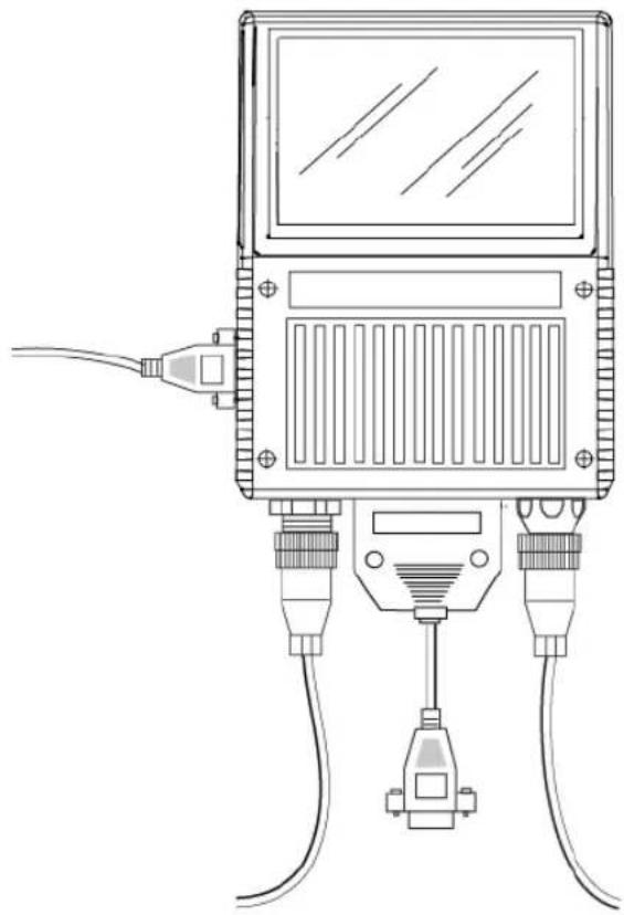
natural_image
Line drawing of a handheld electronic device with two connectors and a screen (no text or symbols)Hardware Required
Caution: Be sure that all cables are connected BEFORE applying power to the system. Always power down BEFORE disconnecting any cables.
| Item Description Part Number | |
| 1 MS-890 Industrial Automation Scanner FIS-0890-0001G, -0002G | |
| 2 9-Pin Configuration Cable 61-000010-02 | |
| 3 Power Supply 97-100004-15 | |
| 4 Object Detector (optional) 99-000004-01 | |
| 5 Comm./Serial Cable 61-000034-02 |
Note: Standalone configuration shown above.
Step 2 — Connect the System
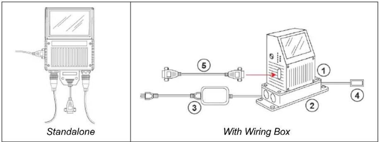
text_image
Standalone With Wiring BoxCaution: Be sure that all cables are connected BEFORE applying power to the system. Always power down BEFORE disconnecting any cables.
Connecting the MS-890 Standalone
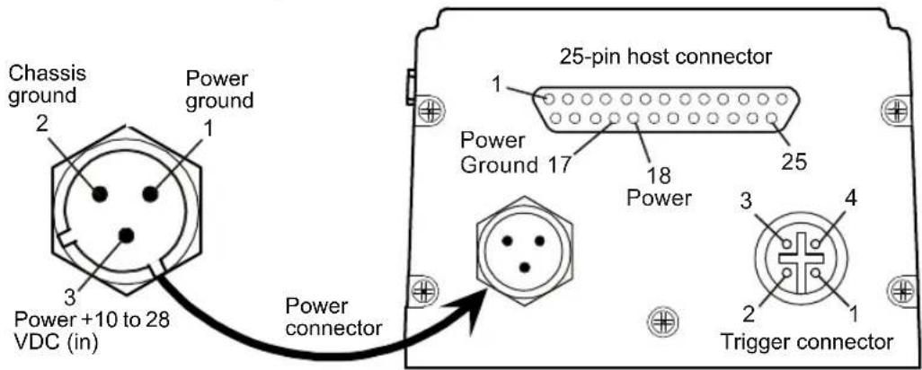
- Attach the configuration cable to either the 9-pin (preferred) or 25-pin connector (on bottom of unit) to configure, test, and default the scanner.
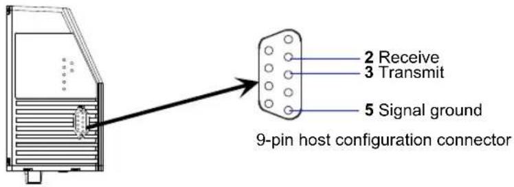
text_image
2 Receive 3 Transmit 5 Signal ground 9-pin host configuration connector- Attach the power supply cable to the 3-pin power connector on the bottom of the scanner.
text_image
Chassis ground Power ground 1 2 3 Power +10 to 28 VDC (in) Power connector 25-pin host connector 1 Power Ground 17 18 Power 25 3 4 2 Trigger connectorConnect the System
Connecting the MS-890 with Wiring Box
- Be sure that the wiring box power cord is not plugged in.
- Connect the scanner to the host computer.
- Use the 9-pin configuration connector shown below to connect with your computer. This port is useful for setting up, testing, and defaulting the scanner.
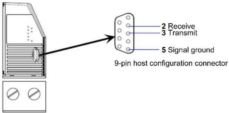
text_image
2 Receive 3 Transmit 5 Signal ground 9-pin host configuration connector- Connect power to the wiring box.
- Apply power to the wiring box and confirm that the LED next to the right side power terminal is green and not red.
- Disconnect power.
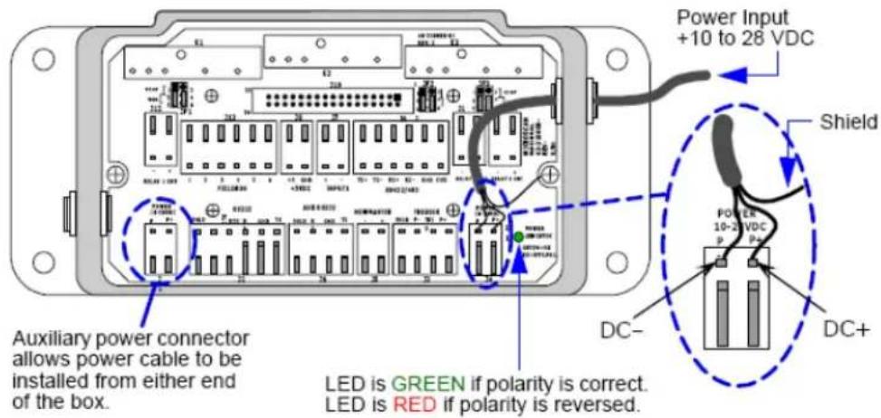
text_image
Power Input +10 to 28 VDC Shield Auxiliary power connector allows power cable to be installed from either end of the box. LED is GREEN if polarity is correct. LED is RED if polarity is reversed.- Plug the ribbon cable (provided with wiring box) into the bottom of the scanner.
- Attach the scanner to the wiring box with the 4 screws provided.
- Power-on the scanner.
Step 3 — Position Scanner and Symbol
- Set up a symbol at the distance that will be used in your application.
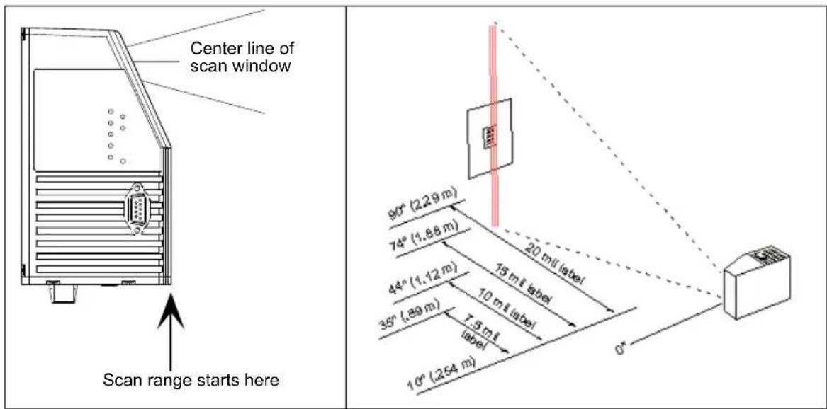
text_image
Center line of scan window Scan range starts here 90° (2.29 m) 74° (1.88 m) 44° (1.12 m) 35° (.89 m) 10° (.254 m) 20 mil label 15 mil label 10 mil label 7.5 mil label 0°Note: Code 39 is the default symbology enabled. If you are uncertain as to the symbology type in your application, enable all symbologies by clicking the Autodiscriminate button in EZ Mode.
Important: If using Interleaved 2 of 5 symbols in your application, verify that the number of characters in the symbols being scanned matches the symbol length enabled for the Interleaved 2 of 5 symbology (default is 10 and 6).
Step 4 — Install ESP
Easy Setup Program (ESP) is Microscan's proprietary setup and testing application. The purpose of ESP is to provide a quick and easy way to set up and configure Microscan products.
When the MS-890 is connected to a host computer (Windows Vista, XP, or 2000), ESP can be used to set up communication with a host, configure various firmware settings, and control verification processes.
Important: To migrate MS-880 settings to MS-890 settings in ESP, refer to the beginning of Chapter 2, Using ESP.
If installing from the Microscan Tools Drive:
- Insert the Microscan Tools Drive into a USB port on your computer.
- Choose ESP Software from the main menu.
- Select the Current Version of ESP and follow the file download prompts.
If downloading from the Microscan website:
- Go to http://www.microscan.com/downloadcenter
- Create a new "myMicroscan" member account or, if you are already a member, enter your user name and password.
- Click the Download Software link and extract the latest version of ESP to a directory of your choice. Note where your ESP.exe file is stored on your hard drive.
- At the end of the installation process, the following icon will appear on your desktop:

- Click the ESP icon to start the program.
System Requirements for ESP
• 233 MHz Pentium PC
- Windows 8, 7, Vista, or XP operating system (32-bit or 64-bit)
- Internet Explorer 5.0 or higher
• 128 MB RAM or greater; 160 MB free disk space
- 800 x 600 256 color display (1024 x 768 32-bit color recommended)
Step 5 — Select Model
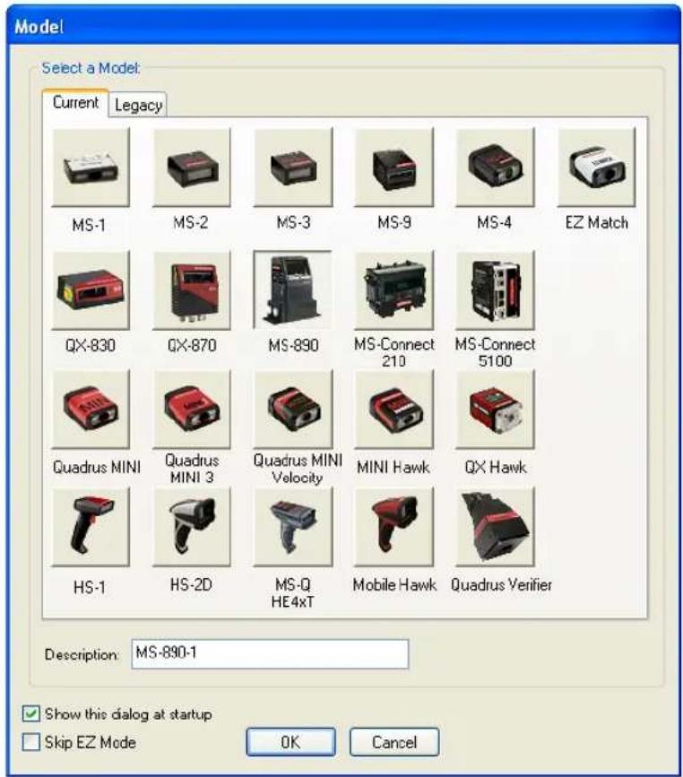
When you start ESP, this menu will appear:
text_image
Model Select a Model: Current Legacy MS-1 MS-2 MS-3 MS-9 MS-4 EZ Match QX-830 QX-870 MS-890 MS-Connect 210 MS-Connect 5100 Quadrus MINI Quadrus MINI 3 Quadrus MINI Velocity MINI Hawk QX Hawk HS-1 HS-2D MS-Q HE4xT Mobile Hawk Quadrus Verifier Description: MS-890-1 Show this dialog at startup Skip EZ Mode OK Cancel- Select the MS-890 from the menu and click OK. If you do not want to make this selection every time you start ESP, uncheck "Show this dialog at startup".
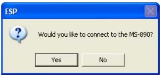
- Click Yes when the following dialog appears:
text_image
ESP Would you like to connect to the MS-890? Yes No
Note: If you need to select another model later, click the Switch Model button near the top of the screen.
Autoconnect
Step 6 — Autoconnect
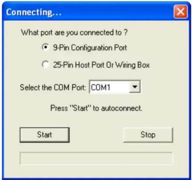
- Select the appropriate port and click Start when the following dialog appears.
text_image
Connecting... What port are you connected to ? ● 9-Pin Configuration Port ○ 25-Pin Host Port Or Wiring Box Select the COM Port: COM1 Press "Start" to autoconnect. Start StopNote: If your communications port is not the default COM1, use the dropdown menu to change your port.
Once you have chosen the correct port, click Start to connect. Start When you are connected, you will see the green connection indicator in the status bar at the bottom right of your screen:

text_image
CONNECTED Point-to-Point COM1 115.2K : N : 8 : 1- If the connection attempt fails, click the Autoconnect button, select a different communications port, and try again.
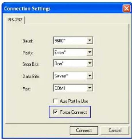
text_image
Connection Settings RS-232 Baud: 9600" Purity: Even" Stop Bits: One" Data Bits: Seven" Port: COM1 Aux Port In Use Force Connect Connect CancelNote: If your RS-232 host settings cannot be changed to match the scanner's settings, select Connect... from the Connect menu in the menu toolbar, and then click the Force Connect box when you see the dialog shown at left.
Step 7 — Receive Settings
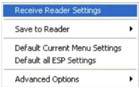
To copy the scanner's memory settings into ESP, right-click in the configuration window and select Receive Reader Settings from the dropdown menu.
Receive Reader Settings
text_image
Receive Reader Settings Save to Reader Default Current Menu Settings Default all ESP Settings Advanced OptionsWhen you select Receive Reader Settings, the settings from the scanner's memory are sent to ESP.
Calibrate
Step 8 — Calibrate
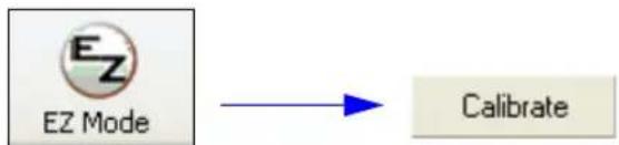
- Click the Calibration button in EZ Mode or in the Calibration view.
flowchart
graph LR
    A["EZ Mode"] --> B["Calibrate"]
-
Allow some time for the scanner to cycle through the focus, gain, and tracking settings. Do not move or disturb the scanner or test symbol while calibration is in progress.
-
When calibration is complete, the settings that provided the highest read rate will be selected. You will see one of the following messages: Calibration Passed, Calibration Failed, or Original Settings Were Optimal.
Note: To silence the beeper, interrupt scanning by removing or blocking the test symbol, or send a
If calibration fails, try the following:
- Check the read range for your particular symbol density.
- Examine symbol quality and try a different sample symbol.
- Slightly skew or tilt the symbol or scanner to minimize specular reflection.
- Verify that the correct symbology is enabled.
Step 9 — Test Read Rate
Important: To receive symbol data through the 9-pin configuration port, you must enable the port with the following command:
- Position the symbol in front of an operational MS-890 scanner.
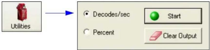
- Click the Utilities button.
- Click the Start button in the Read Rate view.
flowchart
graph LR
    A["Utilities"] --> B["Decodes/sec"]
    A --> C["Percent"]
    B --> D["Start"]
    C --> E["Clear Output"]
If calibration has passed, the scanner sends data to the host computer and emits a beep (if the beeper is enabled) for each good read.
Move your symbol toward the scanner and away from the scanner until the decode rates drop off in each direction. This will give you a sense of the depth of field (inner and outer ranges) for your symbol's density and range.
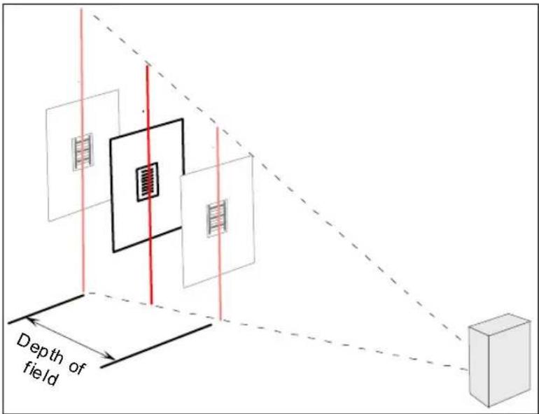
text_image
Depth of fieldNote: If the scanner is in the default Continuous Read mode and not in read rate or calibration routine, it will read and beep repeatedly as long as a readable symbol remains in the read range and the read cycle configuration has not changed.
- To end the read rate test, right click Read Rate and select the Stop button.
Step 10 — Configure the Scanner in ESP
To make setup changes to the MS-890, click the App Mode button.
The following modes are accessible by clicking the buttons in the first row of App Mode icons:
- Test and Calibrate the scanner in EZ Mode.
- Establish communications between ESP and the scanner by clicking the Autoconnect button.
- Send or receive commands by clicking the Send/Recv button.
- Switch reader models by clicking the Switch Model button.
- Click the Parameters button to make changes to tree control settings.
- Click the Setup button to adjust and test scanner settings in Calibration, Raster Setup, Laser Framing, Configuration Database, Ordered Output, and Output Format.
- Access the Terminal, where you can view symbol data and enter serial commands.
- Review status settings or make changes to operational commands in Utilities.
Step 11 — Save Configuration in ESP
To make changes to a configuration setting:
- Left click on the + to expand the desired tree.
- Double click on the desired parameter and click once in the selection box to view options.
- Place your cursor in the selection box, scroll down to the setting you want to change, and click once on the setting.
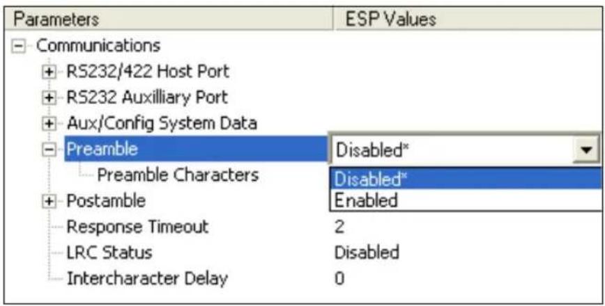
text_image
Parameters ESP Values Communications + RS232/422 Host Port + RS232 Auxiliary Port + Aux/Config System Data Preamble Disabled* Preamble Characters Disabled* Postamble Enabled Response Timeout 2 LRC Status Disabled Intercharacter Delay 0- Left click again on the open screen to complete your selection.
- Right click on the open screen and select Save to Reader to implement the command in the scanner.
Saving Options
- Send, No Save. Changes will be lost when power is re-applied to the scanner.
- Send and Save. This activates all changes in current memory and saves to the scanner for power-on.
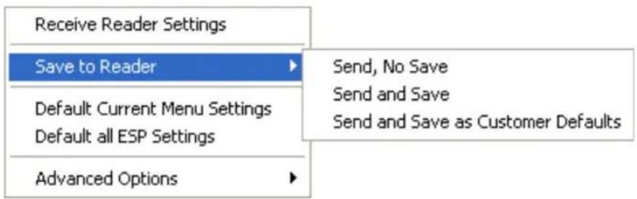
text_image
Receive Reader Settings Save to Reader Default Current Menu Settings Default all ESP Settings Advanced Options Send, No Save Send and Save Send and Save as Customer DefaultsSave Configuration in ESP
Using ESP
Contents
EZ Mode....2-2
Application Mode....2-3
Menu Toolbar 2-4
Autoconnect 2-12
View 2-14
Navigating in ESP 2-15
Send/Receive Options 2-16
This section is designed to help you understand the basic structure and elements of ESP (Easy Setup Program).
When you open ESP, unless otherwise specified in the ESP Preferences dialog accessible from the Options heading on the menu toolbar, you will enter EZ Mode for initial setup.
From there, you can enter Application Mode (App Mode) and access several configuration menus (Communications, Read Cycle, Symbologies, I/O Parameters, Symbol Quality, Matchcode, and Diagnostics), a Camera setup interface, a Terminal interface, a Utilities interface, and an Output Format interface.
For ESP system requirements, see System Requirements for ESP in Chapter 1, Quick Start
Important: If you are switching from an MS-880 to an MS-890 in your application, follow these steps when you open ESP:
- With your MS-890 connected to the host computer, open your most recent MS-880 .esp file.
- Connect to the MS-890 and send all settings.
- Click the Switch Model button at the top of the ESP view. When you see the model menu, select the MS-890.
- Receive settings.
Note: After receiving settings, you can delete the previous MS-880 model by opening the Model dropdown menu from the menu toolbar, selecting Remove Model, and selecting MS-880.
EZ Mode
EZ Mode
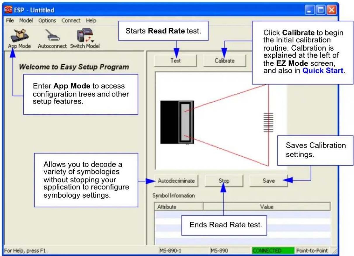
In EZ Mode you are presented with the Locate, Calibrate, and Test options. After connecting to your scanner, EZ Mode is the screen you will see. You will be provided with on-screen instructions that will help you with positioning, testing, and calibration.
Test
Click the Test button to start the Read Rate test for a quick indication of the scanner's read capabilities and the limits of your application. When Decodes per Second is unchecked, the test will count the percentage of decodes relative to the number of actual scans. Click Stop to end the test.
Calibrate
The calibration routine that will optimize the scanner by comparing Read Rates at various camera and image processing settings.
text_image
ESP - Untitled File Model Options Connect Help App Mode Autoconnect Switch Model Starts Read Rate test. Test Calibrate Click Calibrate to begin the initial calibration routine. Calibration is explained at the left of the EZ Mode screen, and also in Quick Start. Welcome to Easy Setup Program Enter App Mode to access configuration trees and other setup features. Allows you to decode a variety of symbologies without stopping your application to reconfigure symbology settings. Saves Calibration settings. Symbol Information Autodiscriminate Stop Save Attribute Value Ends Read Rate test. For Help, press F1. MS-890-1 MS-890 CONNECTED Point-to-PointApplication Mode
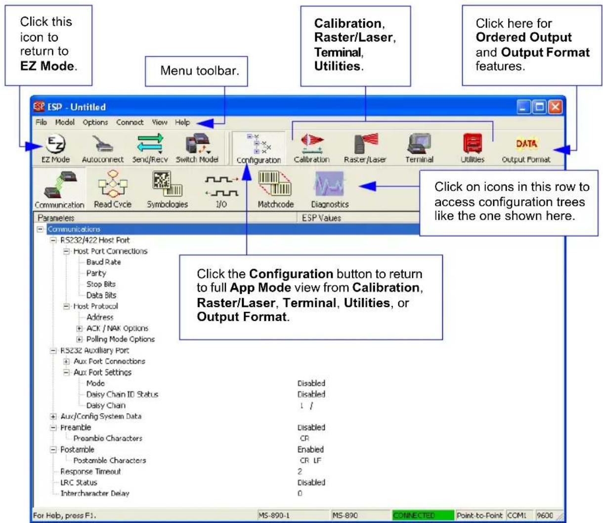
From EZ Mode, you can click on the App Mode button to access specific configuration menus, Utilities tools, Camera setup, Output Format options, and a Terminal window where serial commands can be entered.
Note: The App Mode and EZ Mode buttons appear in the same position to allow easy switching between these primary modes.
text_image
Click this icon to return to EZ Mode. Menu toolbar. Calibration, Raster/Laser, Terminal, Utilities. Click here for Ordered Output and Output Format features. ESP - Untitled File Model Options Connect View Help EZ Mode Autoconnect Send/Recv Switch Model Configuration Calibration Raster/Laser Terminal Utilities DATA Communication Read Cycle Symbologies 1/0 Matchcode Diagnostics Parameters ESP Values Communications RS232/422 Host Port Host Port Connections Baud Rate Parby Stop Bits Data Bits Host Protocol Address ACK / NAK Options Polling Mode Options RS232 Auxiliary Port Aux Port Connections Aux Port Settings Mode Disabled Daisy Chain ID Status Disabled Daisy Chain 1 / Aux/Config System Data Preamble Disabled Preamble Characters CR Postamble Enabled Postamble Characters CR LF Response Timeout 2 LRC Status Disabled Intercharacter Delay 0 For Help, press F1. MS-890-1 MS-890 CONNECTED Point-to-Point COMI 9600Note: For specific information on any of the icons shown above in the operations bar or configuration bar, see the corresponding sections of this manual.
Menu Toolbar
Menu Toolbar
File > New
Whenever New is selected, the default configuration of ESP is loaded.
Open/Save
When Save or Save As is selected, the ESP configuration is saved to the host computer's hard drive and available whenever the same file is selected under Open.
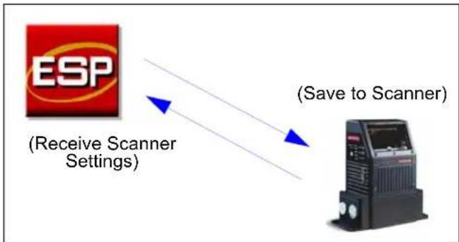
Important: When you save menu changes to your hard drive, these changes are not saved to your scanner. The illustration below shows how settings can be saved and received between ESP and the scanner, and ESP and the host hard drive.
flowchart
graph LR
    A["ESP"] -->|Receive Scanner Settings| B["(Save to Scanner)"]
    B -->|Data Transfer| A
| File | |
| New | Ctrl+N |
| Open... | Ctrl+O |
| Save | Ctrl+S |
| Save As... | |
| Print... | Ctrl+P |
| Import... | |
| Export... | |
| Recent File | |
| Exit | |
Import/Export
Import converts the ASCII settings from a text file to ESP configuration settings. Export converts the active ESP configuration settings to an ASCII text file.
Model
In Model you can select any of the models shown in ESP's model menu. When you choose another model, your current connection to your present model will be terminated.
To connect to another model, select New Model, choose a new model from the menu, and click OK.
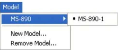
text_image
Model MS-890 ▶ • MS-890-1 New Model... Remove Model...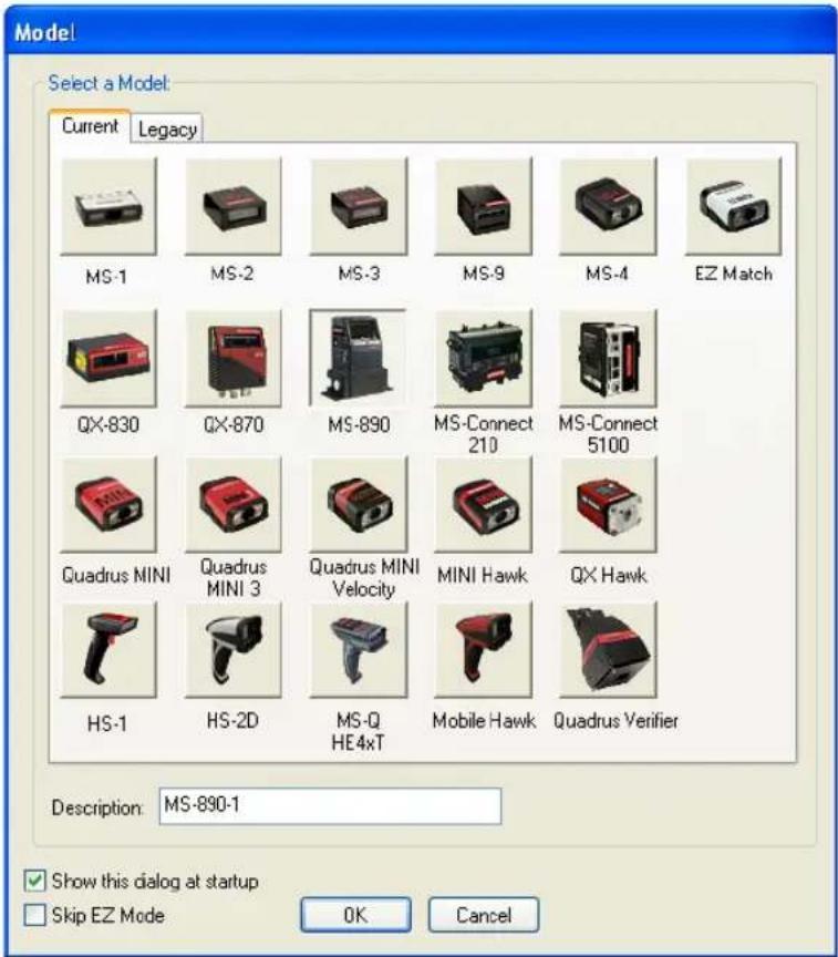
text_image
Model Select a Model Current Legacy MS-1 MS-2 MS-3 MS-9 MS-4 EZ Match QX-830 QX-870 MS-890 MS-Connect 210 MS-Connect 5100 Quadrus MINI Quadrus MINI 3 Quadrus MINI Velocity MINI Hawk QX Hawk HS-1 HS-2D MS-Q HE4xT Mobile Hawk Quadrus Verifier Description: MS-890-1 ✓ Show this dialog at startup ☐ Skip EZ Mode OK CancelNote: All the models you have enabled by selecting will continue to appear in the Model menu and that the same menu is repeated when clicking the Switch Model icon.
When you save your ESP file, you will be saving the settings of all the models defined in a single ESP file.
Menu Toolbar
Options
The Options menu allows you to save memos and set up ESP Preferences.
Note: Preferences will be saved and loaded into ESP whenever ESP is opened next, whether or not you save the ESP file.
Options
Preferences
Document Memo
Model Memo
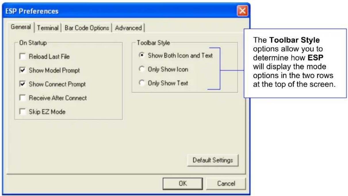
Preferences > General Tab
text_image
ESP Preferences General | Terminal | Bar Code Options | Advanced | On Startup □ Reload Last File ✓ Show Model Prompt ✓ Show Connect Prompt □ Receive After Connect □ Skip EZ Mode Toolbar Style ● Show Both Icon and Text ○ Only Show Icon ○ Only Show Text Default Settings OK Cancel The Toolbar Style options allow you to determine how ESP will display the mode options in the two rows at the top of the screen.Reload Last File
At startup, reloads the last file saved to the host computer's hard drive.
Show Model Prompt
At startup, shows the model menu displaying all supported readers.
Show Connect Prompt
At startup, displays the Would you like to connect to the MS-890? prompt.
Receive After Connect
At startup, loads the scanner's settings into ESP. (This is not recommended if you want to preserve your ESP settings for future use.)
Skip EZ Mode
At startup, skips EZ Mode and opens directly in App Mode.
Preferences > Terminal Tab
text_image
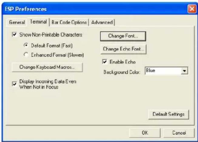
ESP Preferences General Termnal Bar Code Options Advanced ✓ Show Non-Printable Characters Default Format (Fast) Enhanced Format (Slower) Change Keyboard Macros... ✓ Display Incoming Data Even When Not in Focus Change Font... Change Echo Font... ✓ Enable Echo Background Color: Blue Default Settings OK CancelShow Non-Printable Characters
When Show Non-Printable Characters is enabled, characters such as "CRLF" will be displayed in the Terminal window. When Enhanced Format is checked, the characters are displayed with more detailed formatting.
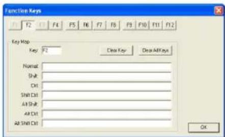
Change Keyboard Macros
Clicking the Change Keyboard Macros button brings up the Function Keys dialog. In this dialog you can select the desired function key and then enter your macro keystrokes in the associated key map. For example, to make Ctrl-F2 the keystroke to send a trigger character, select F2, then in the Ctrl row, enter
text_image
Function Keys F2 F4 F5 F6 F7 F8 F9 F10 F11 F12 Key Map Key: F2 Clear Key Clear All Keys Name: Shift: CH: Shift CH: All Shift: All Chl: All Shift Chl: OKNote: The F1 key is reserved for opening ESP Help and the F3 key is reserved for the Find Next function.
Change Font
Allows you to modify the font used for decode data received from the scanner on the Terminal screen.
Change Echo Font
Allows you to modify the font used for command characters typed into the Terminal view.
Enable Echo
Allows you to enter command characters in Terminal.
Display Incoming Data Even When Not in Focus
When Display Incoming Data Even When Not in Focus is enabled, data from the scanner will continue to appear in the terminal even when ESP is not the top window.
Menu Toolbar
Preferences > Bar Code Options Tab
text_image
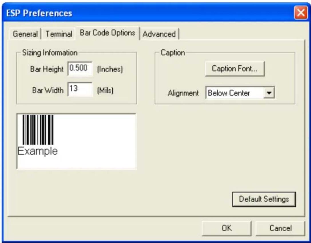
ESP Preferences General | Terminal | Bar Code Options | Advanced | Sizing Information Bar Height 0.500 (Inches) Bar Width 13 (Mils) Caption Caption Font... Alignment Below Center Example Default Settings OK CancelThe Bar Code Options dialog allows you to set the size of user-created symbols.
Sizing Information
Sets the bar width or module width (in mils, or thousandths of an inch) of user-created symbols. Example: A bar width of 13 is 0.013 inches.
Caption
Allows you to choose the font of human-readable captions (if symbol captions are required), and to determine the orientation of captions in relation to symbols.
Note: Symbols can be created using the Bar Code Dialog.
Preferences > Advanced Tab
text_image
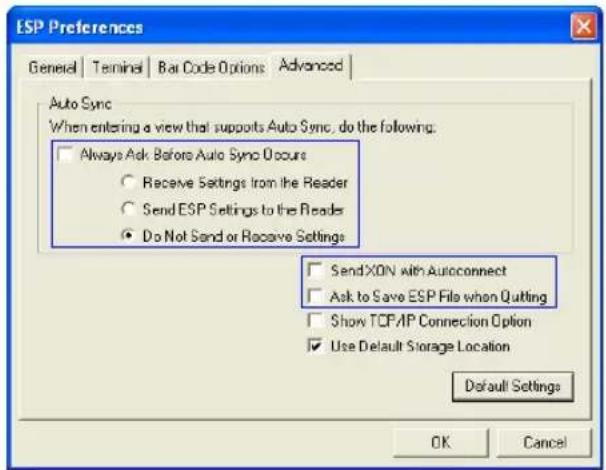
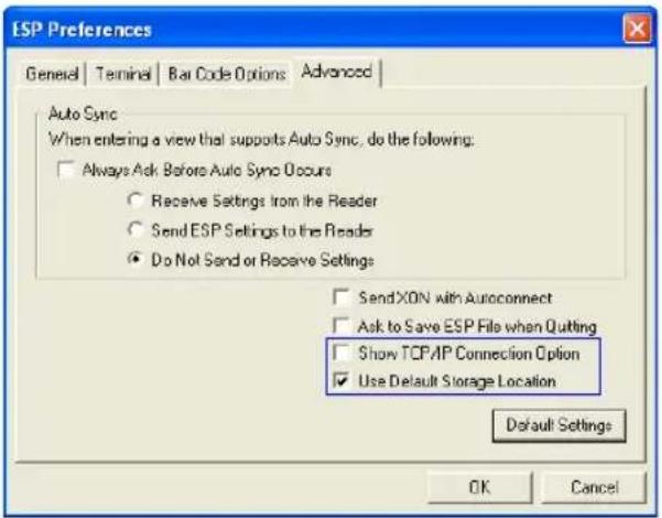
ESP Preferences General | Terminal | Bar Code Options | Advanced | Auto Sync When entering a view that supports Auto Sync, do the following: □ Always Ask Before Auto Sync Occurs ○ Receive Settings from the Reader ○ Send ESP Settings to the Reader ● Do Not Send or Receive Settings □ SendXON with Autoconnect □ Ask to Save ESP File when Quitting □ Show TCP/IP Connection Option ☑ Use Default Storage Location Default Settings OK CancelThe Auto Sync options at the top of the Advanced tab allow you to determine whether Auto Sync will be enabled automatically in sections of ESP where it is used, or if it will ask you before it enables Auto Sync functions.
Always Ask Before Auto Sync Occurs
If you check this option box, you are then able to determine what specific Auto Sync functions will be enabled. Receive Settings from the Reader will automatically send the scanner's settings to ESP when Auto Sync is enabled. Send ESP Settings to the Reader will automatically send all scanner configuration settings chosen in ESP to the scanner. Do Not Send or Receive Settings creates a condition in which Auto Sync will not automatically send scanner settings to ESP, or send ESP settings to the scanner.
Send XON with Autoconnect
Sends an XON (Begin Transmission) command to the scanner before starting the Autoconnect routine.
Ask to Save ESP File when Quitting
When enabled, prompts the user to save a .esp file when ending a session.
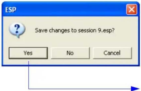
text_image
ESP Save changes to session 9.esp? Yes No CancelThe .esp file will be saved in the location of your choice.
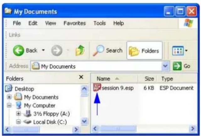
text_image
My Documents File Edit View Favorites Tools Help Links Back Search Folders Address My Documents Go Folders Desktop My Documents My Computer 3½ Floppy (A:) Local Disk (C:) Name Size Type session 9.esp 6 KB ESP DocumentMenu Toolbar
Preferences > Advanced Tab (cont.)
text_image
ESP Preferences General | Terminal | Bar Code Options | Advanced | Auto Sync When entering a view that supports Auto Sync, do the following: □ Always Ask Before Auto Sync Occurs ○ Receive Settings from the Reader ○ Send ESP Settings to the Reader ● Do Not Send or Receive Settings □ SendXON with Autoconnect □ Ask to Save ESP File when Quitting □ Show TCP/IP Connection Option ☑ Use Default Storage Location Default Settings OK CancelShow TCP/IP Connection Option
When enabled, shows a TCP/IP option on the Select Protocol dialog.
Note: This option should only be selected if you intend to connect using an Ethernet adapter.
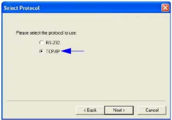
text_image
Select Protocol Please select the protocol to use: ○ RS-232 ● TCP/IP < Back Next > CancelUse Default Storage Location
When enabled, automatically stores data in ESP's Application Data folder.
Document Memo
The information you type in the Document Memo field will appear in a context-sensitive text box whenever your cursor hovers over the Document Memo item on the Options menu.
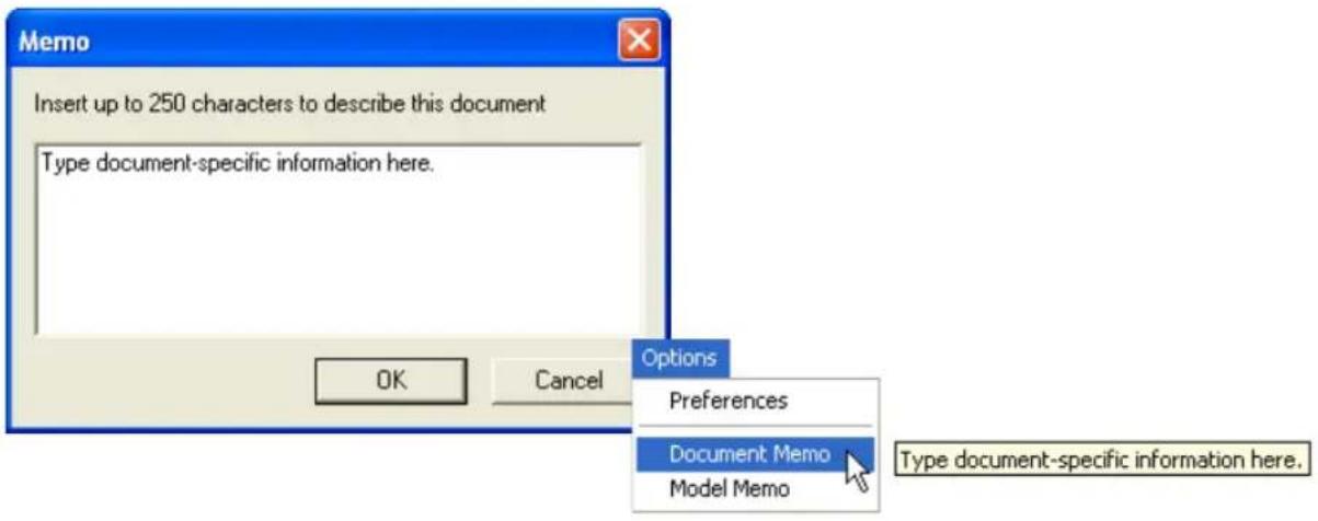
text_image
Memo Insert up to 250 characters to describe this document Type document-specific information here. OK Cancel Options Preferences Document Memo Model Memo Type document-specific information here.Model Memo
Similar to Document Memo, the information you type in the Model Memo field will appear in a context-sensitive text box whenever your cursor hovers over the Model Memo item on the Options menu. Memos created in Model Memo are specific to the model enabled when the message was created.
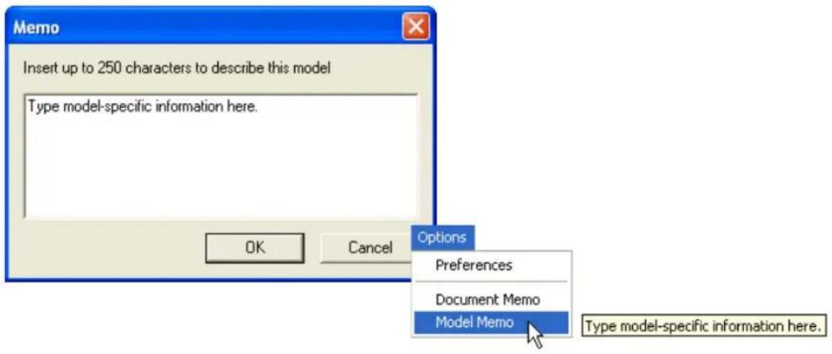
text_image
Memo Insert up to 250 characters to describe this model Type model-specific information here. OK Cancel Options Preferences Document Memo Model Memo Type model-specific information here.Note: Memos must be saved in a .esp file if you want them to available in your next session. If you do not save your current session, any memos that you have entered during the session will be discarded, and will be unavailable in your next session.
Autoconnect
Autoconnect
- You can use Autoconnect to establish a connection between the scanner and the host.
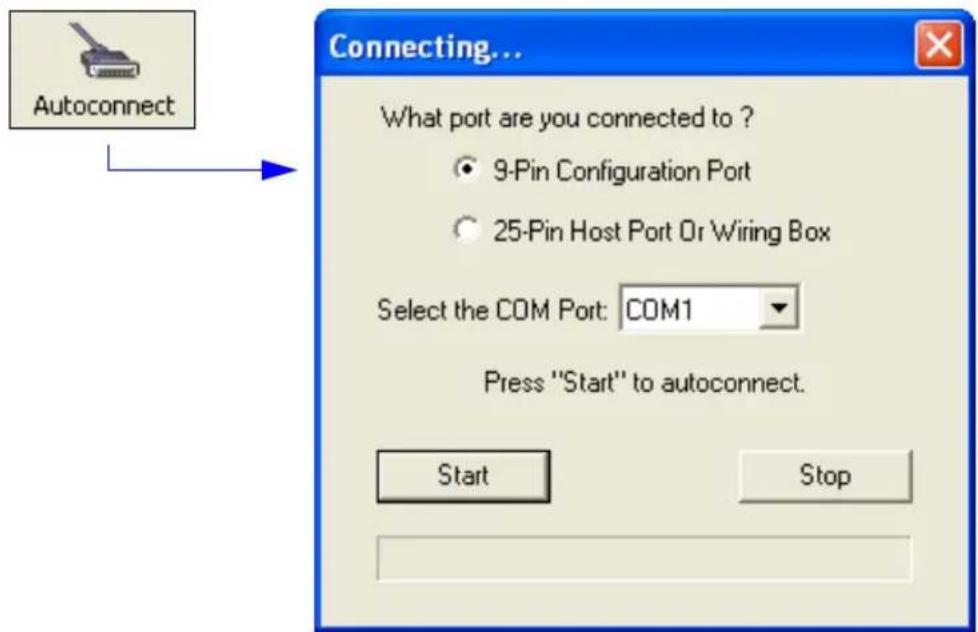
text_image
Connecting... What port are you connected to ? ● 9-Pin Configuration Port ○ 25-Pin Host Port Or Wiring Box Select the COM Port: COM1 Press "Start" to autoconnect. Start Stop- If your communications port is not the default COM1, use the dropdown menu to change ports.
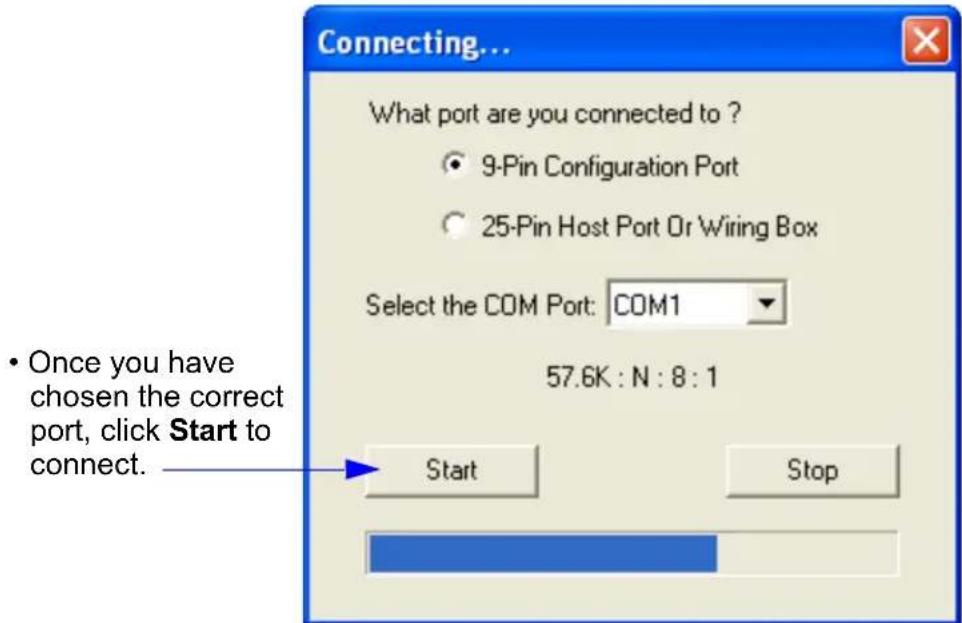
text_image
Connecting... What port are you connected to ? ● 9-Pin Configuration Port ○ 25-Pin Host Port Or Wiring Box Select the COM Port: COM1 57.6K : N : 8 : 1 • Once you have chosen the correct port, click Start to connect. Start StopWhen you are connected, you will see the green connection indicator in the status bar at the bottom right of your screen:

Autoconnect (cont.)
If your RS-232 host settings cannot be changed to match the scanner's settings:
- Click Connect on ESP's menu toolbar, and then select Connection Wizard.
- When the Select Protocol dialog appears, select RS-232 and click Next.
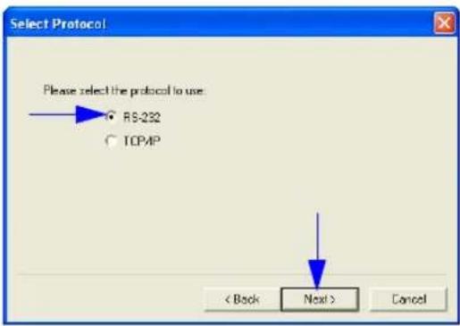
text_image
Select Protocol Please select the protocol to use RS-232 TCPMP < Back Next > Cancel- When the RS-232 dialog appears, check the Force Connect box and click the Connect button.
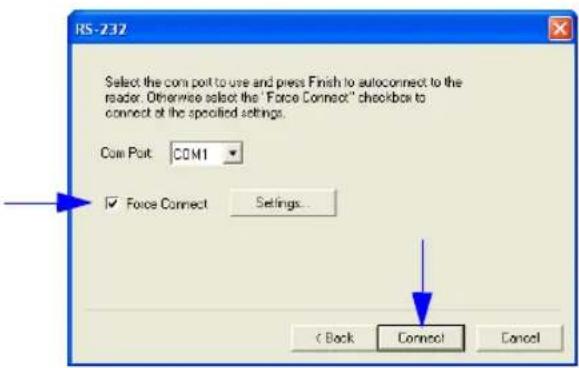
text_image
RS-232 Select the com port to use and press Finish to autocornect to the reader. Otherwise select the "Force Connect" checkbox to connect at the specified settings. Com Port: COM1 ✓ Force Connect Settings... < Back Connect CancelView
View
The View menu allows you to move quickly between interfaces without using the icon buttons on the App Mode toolbar. It also allows you to access the Bar Code Dialog.
Bar Code Dialog
In the Bar Code Dialog you can create symbols by typing the text you wish to encode. This is a useful tool for creating configuration symbols, allowing you to configure your scanner by reading the symbols you create.
View
Configuration
Calibration
Raster
Terminal
Utilities
Output Format
Bar Code Dialog
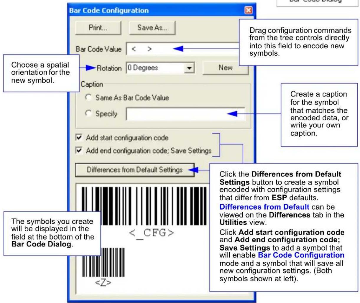
text_image
Bar Code Configuration Print... Save As... Bar Code Value < > Rotation 0 Degrees New Caption Same As Bar Code Value Specify Add start configuration code Add end configuration code; Save Settings Differences from Default Settings Click the Differences from Default Settings button to create a symbol encoded with configuration settings that differ from ESP defaults. Differences from Default can be viewed on the Differences tab in the Utilities view. Click Add start configuration code and Add end configuration code; Save Settings to add a symbol that will enable Bar Code Configuration mode and a symbol that will save all new configuration settings. (Both symbols shown at left). Choose a spatial orientation for the new symbol. Create a caption for the symbol that matches the encoded data, or write your own caption. The symbols you create will be displayed in the field at the bottom of the Bar Code Dialog.See Bar Code Configuration on page A-23 for more information about configuring the MS-890 by decoding symbols.
Navigating in ESP
To change scanner settings, or to access the Calibration, Raster/Laser, Terminal, Utilities, or Output Format views, click the App Mode button.
To return to EZ Mode, click the EZ Mode button.
To make changes to configuration settings in the tree controls:
- Left-click on the + to expand menu items.
- Double-click the desired parameter and single-click in the selection box to view options.
- Place your cursor in the selection box, scroll down to the setting you want to change, and single-click the setting.
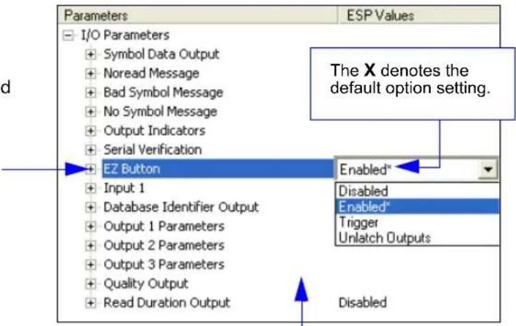
text_image
Parameters I/O Parameters Symbol Data Output Noread Message Bad Symbol Message No Symbol Message Output Indicators Serial Verification EZ Button Input 1 Database Identifier Output Output 1 Parameters Output 2 Parameters Output 3 Parameters Quality Output Read Duration Output ESP Values The X denotes the default option setting. Enabled* Disabled Enabled* Trigger Unlatch Outputs Disabled- Left-click again on the open screen to complete the selection.
- Right-click on the open screen and select Save to Reader to implement the command in the scanner. You can send the command without saving it, or you can send and save the command simultaneously.
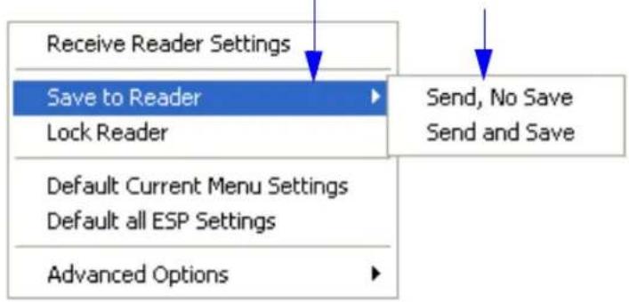
text_image
Receive Reader Settings Save to Reader Lock Reader Default Current Menu Settings Default all ESP Settings Advanced Options Send, No Save Send and SaveSend/Receive Options
To access Receive, Save, and Default options, click the Send/Recv button. You can also access these options by right-clicking in any of the configuration views.
Receiving
From the Send/Recv menu, select Receive Reader Settings.
Caution: Do not select this option if you do not want to upload the scanner's settings. For example, if your ESP file has a number of custom settings that you want to maintain and download into the scanner, these settings would be lost by choosing Yes.
This is useful if you want to receive (upload) the scanner's settings and save them as a file for future use. For example, if your scanner has settings that you do not want to change, choosing Yes would allow you to load those settings to ESP and save them in an ESP file for later retrieval.
Receiving the scanner's settings will also assure that you will not be subsequently saving any unwanted changes that you or someone else has made previously in ESP.
Saving
Send, No Save ()
Saves ESP settings to current memory.
Send and Save ()
Activates all changes in current memory and saves to the scanner for power-on.
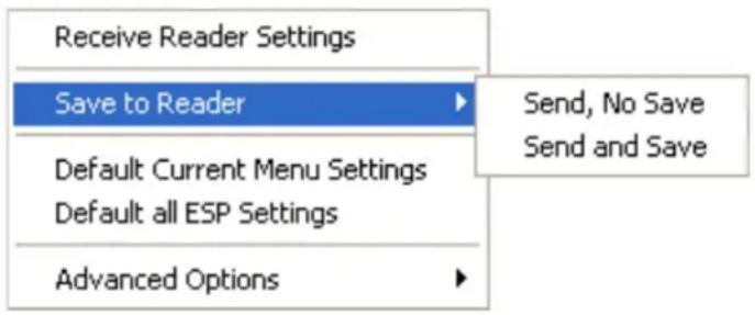
text_image
Receive Reader Settings Save to Reader Default Current Menu Settings Default all ESP Settings Advanced Options Send, No Save Send and SaveDefaulting
When you select Default Current Menu Settings or Default all ESP Settings, you are only defaulting the ESP settings.
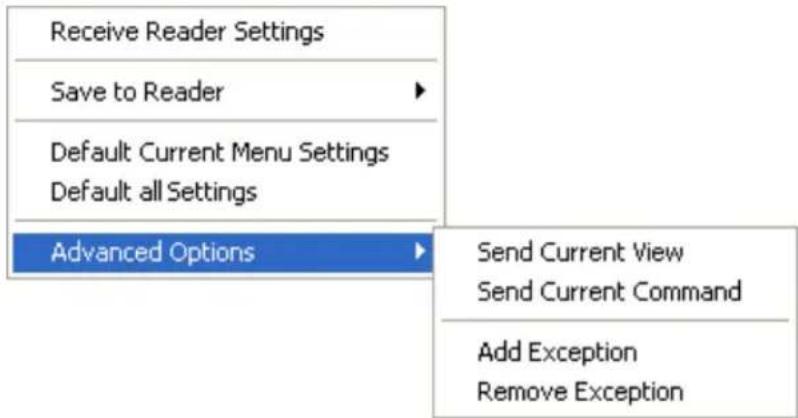
Advanced Options
text_image
Receive Reader Settings Save to Reader Default Current Menu Settings Default all Settings Advanced Options Send Current View Send Current Command Add Exception Remove ExceptionSend Current View
This is the same as Save to Reader > Send No Save except that only the commands in the current configuration tree are sent.
Send Current Command
This is the same as Send Current View, except that it saves only the command that is currently selected.
Add / Remove Exception
After you perform a Receive Reader Settings command ^1 and you click on the Add Exception option, you may see a list of serial commands. These are commands that may be in your scanner's firmware, but not included in, or different from, your current version of ESP. You can edit these commands by double-clicking on them and changing them as needed. It is important to note that these commands will be saved to your scanner whenever you send a Save to Reader command, or an or a
Also, if there is a corresponding ESP menu item, the ESP Value column for that item will be blank following a Receive Reader Settings command.
Send/Receive Options
Communications
Contents
Communications by ESP.... 3-2
Communications Serial Commands 3-2
RS-232/422 Host Port 3-3
Host Port Parameters.... 3-4
Host Protocol 3-5
Poll Address 3-7
ACK / NAK Options 3-8
Polling Mode Options 3-9
Auxiliary Port Protocol 3-10
Daisy Chain Autoconfigure 3-19
Daisy Chain Scanner ID 3-20
Auxiliary/Configuration Port System Data 3-21
Preamble 3-22
Postamble....3-23
LRC Status 3-24
Intercharacter Delay 3-25
Response Timeout 3-26
With Microscan's ESP (Easy Setup Program), configuration changes can be made in the ESP menus, then sent and saved to your scanner. The user can also send serial commands to the scanner via the ESP's Terminal window.
This section includes connecting parameters and options for communicating by the auxiliary port and various interfaces.
Note: When assigning characters in user-defined fields, the characters NUL, <, >, and , can only be entered through embedded menus, not through ESP or serial commands.
Note: Default settings for establishing communications are:
Baud = 9600
Parity = Even
Stop Bits = One
Data Bits = Seven
Flow Control = None
Communications by ESP
Click this button to bring up the Applications menu.
Click this button to bring up the Communication menu.
text_image
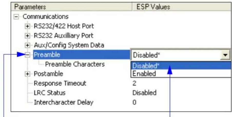
Parameters ESP Values Communications + RS232/422 Host Port + RS232 Auxiliary Port + Aux/Config System Data Preamble Disabled* Preamble Characters Disabled* + Postamble Enabled Response Timeout 2 LRC Status Disabled Intercharacter Delay 0To open nested options, single-click the +.
To change a setting, double-click the setting and use your cursor to scroll through the options.
Communications Serial Commands
Command Title Command Format
| Host Port Parameters | |
| Aux Port Protocol | |
| Host Protocol | |
| Preamble | |
| Postamble | |
| Response Timeout | |
| Intercharacter Delay | |
| LRC | |
| Auxiliary/Configuration Port System Data | |
| ACK/NAK Options | |
| Polling Mode Options | |
| Daisy Chain Autoconfigure | |
| Daisy Chain Scanner ID |
RS-232/422 Host Port
Includes host port connections and host protocols.
Communications Options
You can communicate with the scanner through the following ports:
- 9-pin D-sub external connector
- Wiring box
• 25-pin D-sub external connector
Only one port can be used at a time to receive commands.
Communications with Host through the 9-pin Host Port
For the 9-pin configuration port, set the host communications settings as follows: 57.6K baud, 8 data bits, 1 stop bits, and None parity. See Chapter 1, Quick Start, for more information on using the 9-pin port.
Note: The 9-pin configuration port settings are not changeable.
Communications with Host through the 25-pin Port
The default 25-pin host port configuration settings are as follows: 9600, 7, 1, and Even.
Making changes to these communications parameters without corresponding changes in linked device(s) can result in the loss of menu access. If this should occur, connect via the 9-pin port and reset your scanner's host parameters to match the 25-pin defaults.
Communications with Host through the Wiring Box
The settings are the same as those of the 25-pin port. See Chapter 14, Wiring Box, for details on wiring connections.
Host Port Parameters
Important: This applies only to the 25-pin port and wiring box connections (not for 9-pin port).
Note: See Communications with Host through the 9-pin Host Port on page 3-3 for 9-pin host port parameters.
Baud Rate (Host Port)
Usage: Can be used to transfer data faster or to match host port settings.
Definition: The rate at which the scanner and host transfer data back and forth.
Serial Cmd:
Default: 9600
Options: 0 = 600 1 = 1200 2 = 2400
$$ 3 = 4 8 0 0 4 = 9 6 0 0 5 = 1 9. 2 \mathrm{K} $$
$$ 6 = 3 8. 4 \mathrm{K} 7 = 5 7. 6 \mathrm{K} 8 = 1 1 5. 2 \mathrm{K} $$
Parity (Host Port)
Usage: Only changed if necessary to match host setting.
Definition: An error detection routine in which one data bit in each character is set to 1 or 0 so that the total number of 1 bits in the data field is even or odd.
Serial Cmd:
Default: Even
Options: 0 = None 1 = Even 2 = Odd
Stop Bits (Host Port)
Usage: Only changed if necessary to match host setting.
Definition: One or two bits added to the end of each character to indicate the end of the character.
Serial Cmd:
Default: One
Options: 0 = One 1 = Two
Data Bits (Host Port)
Usage: Only changed if necessary to match host setting.
Definition: Number of bits in each character.
Serial Cmd:
Default: Seven
Options: 0 = Seven 1 = Eight
Host Protocol
Usage: In general, point-to-point protocols work well in most applications. They require no address and must use RS-232 or RS-422 communications standards.
Definition: Protocols define the sequence and format in which information is transferred between the scanner and the host, or in the case of Polling Mode, between scanners and a concentrator. Important: When using Polling Mode, LRC must be Enabled and Preamble/Postamble must be Disabled.
Serial Cmd:
Default: Point-to-Point
Options: 0 = Point-to-Point
1 = Point-to-Point with RTS/CTS
2 = Point-to-Point with XON/XOFF
3 = Point-to-Point with RTS/CTS and XON/XOFF
4 = ACK/NAK
5 = Polling Mode
Point-to-Point (Standard)
Usage: Used only with RS-232 or RS-422.
Definition: Standard Point-to-Point requires no address and sends data to the host whenever it is available, without any request or handshake from the host.
Serial Cmd:
Point-to-Point with RTS/CTS
Usage: A scanner initiates a data transfer with an RTS (request-to-send) transmission. The host, when ready, responds with a CTS (clear-to-send) and the data is transmitted. CTS and RTS signals are transmitted over two dedicated wires as defined in the RS-232 standard. Used only with RS-232.
Definition: Point-to-Point with RTS/CTS (request-to-send/clear-to-send) is a simple hardware handshaking protocol that allows a scanner to initiate data transfers to the host.
Serial Cmd:
Host Protocol
Point-to-Point with XON/XOFF
Usage: If an XOFF has been received from the host, data will not be sent to the host until the host sends an XON. During the XOFF phase, the host is free to carry on other tasks and accept data from other devices. Used only with RS-232.
Definition: This option enables the host to send the XON and XOFF command as a single byte transmission command of start (^Q) or stop (^S).
Serial Cmd:
Point-to-Point with RTS/CTS and XON/XOFF
Usage: Used only with RS-232.
Definition: This option is a combination of Point-to-Point with RTS/CTS and Point-to-Point with XON/XOFF.
Serial Cmd:
ACK/NAK
Definition: See the ACK / NAK Options command
Serial Cmd:
Polling Mode
Definition: See the Polling Mode Options command
Serial Cmd:
Poll Address
Serial Cmd:
Default: 1
Options: 1 to 50
1 = Poll address 0x1C, Select address 0x1D
2 = Poll address 0x1E, Select address 0x1F
...
50 = Poll address 0x7E, Select address 0x7F
ACK / NAK Options
Definition: These parameters take effect for ACK/NAK
The scanner always follows the protocol in both directions (to and from the host). There is no option to disable it from either direction.
Serial Cmd:
RES-NAK Defaults
RES: (Reset) 0x00 (disabled)
REQ: (Request) 0x00 (disabled)
STX: (Start of Text) 0x00 (disabled)
ETX: (End of Text) 0x00 (disabled)
ACK: (Acknowledge) 0x06
NAK: (Negative Acknowledge) 0x15
The following are general outlines of the ACK/NAK protocol. Items that are framed by brackets ( [ ] ) can either be disabled or enabled. LRC does not include STX, but it does include preamble, postamble, and ETX.
Symbol Data Output
TX to host: [STX] [preamble] SYMBOL DATA [postamble] [ETX] [LRC]
Response from host: ACK/NAK. Sent when LRC, ETX, postamble, or timeout (waiting for more data) are detected (if REQ is disabled) depending on what is enabled.
Commands from Host to Scanner
TX to Scanner: [STX]
Response from Scanner: ACK/NAK. Sent when LRC, ETX, or command-ending angle bracket ‘>’ are received, depending on what is enabled.
Command Response from Scanner to Host
TX to host: [STX] [preamble] COMMAND RESPONSE DATA [postamble] [ETX] [LRC]
Response from host: ACK/NAK. Sent when LRC, ETX, postamble, command-ending angle bracket ‘>’, or timeout (waiting for more data) are detected, depending on what is enabled.
As with Polling Mode
Polling Mode Options
Definition:
These parameters only take effect for Polling Mode
The values of protocol characters can be changed, but the protocol events cannot be disabled. The polling mode address is configured in the
Serial Cmd:
RES-NAK Defaults
RES: (Reset) 0x04 (disabled)
REQ: (Request) 0x05 (disabled)
STX: (Start of Text) 0x02 (disabled)
ETX: (End of Text) 0x03 (disabled)
ACK: (Acknowledge) 0x06
NAK: (Negative Acknowledge) 0x15
Auxiliary Port Protocol
Note: The Aux Port cannot be used when the host port is set to RS-422 or Multidrop. As with the host port parameters, the auxiliary terminal's settings (baud rate, parity, stop bits, and data bits) must be identical with those of the auxiliary device.
Usage: These commands set the communication parameters with the auxiliary port which can be used to configure menus, send data to the host, display data transmissions originating from the host of the scanner, and relay data from other scanners set in tandem (Daisy-Chained). If the scanner's host port needs to be dedicated to the host, but configuration must be done on the fly, the auxiliary port can be set to accept configuration changes by Command Processing.
Definition: An auxiliary port connects the scanner to a remote display or to other scanners that can display or transfer data. As with the host port parameters, the auxiliary terminal's settings (baud rate, parity, stop bits, and data bits) must be identical to those of the auxiliary device.
Aux Port Mode
Note: The Aux Port interacts only with the host port via the 25-pin port except when in Daisy Chain mode. When in Daisy Chain mode, the Aux Port will also interact with the configuration port (9-pin port) or the wiring box network ports.
Definition: Determines the flow of data between the auxiliary port device(s), the scanner, and the host.
Serial Cmd:
Default: Disabled
Options: 0 = Disabled 1 = Transparent 2 = Half Duplex 3 = Full Duplex 4 = Daisy Chain 5 = Command Processing
Transparent (Aux Port Mode)
Usage: Often used in conjunction with handheld scanners. Employs an auxiliary readout to detect mis-applied symbols.
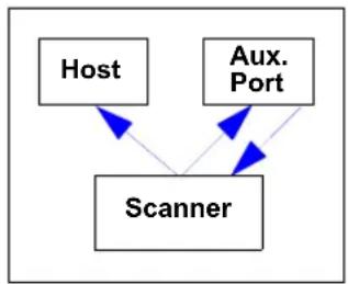
Definition: In Transparent mode data is passed between the auxiliary port and the host. The scanner buffers data from the auxiliary port and echoes the keyed data on the auxiliary port.
Data Initiated from the Auxiliary Port
Auxiliary port data is passed through to the host whenever a return key is pressed at the auxiliary port or symbol data is sent.
Whenever Aux Port data is sent with symbol data, the Aux Port data will appear between the preamble and the symbol data.
Auxiliary port data to the host is always sent with a preamble and a postamble.
If the scanner is in a polled mode to the host, auxiliary port data will still pass through.
flowchart
graph TD
    A["Host"] --> C["Scanner"]
    B["Aux. Port"] --> C["Scanner"]
    B["Aux. Port"] --> C["Scanner"]
Data Initiated from the Scanner
Transmission to the auxiliary port occurs immediately upon a good read.
Scan data to the auxiliary port does not include a preamble or a postamble.
Communications with the auxiliary port is always in Point-to-Point protocol, even if the host is in a polled protocol mode.
Data Initiated from the Host
All host data is echoed to the auxiliary port in unpolled and polled mode.
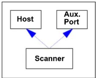
flowchart
graph TD
    A["Host"] --> C["Scanner"]
    B["Aux. Port"] --> C["Scanner"]
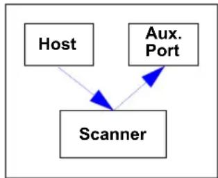
flowchart
graph TD
    A["Host"] --> C["Scanner"]
    B["Aux. Port"] --> C["Scanner"]
Serial Cmd:
1 = Transparent
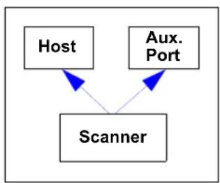
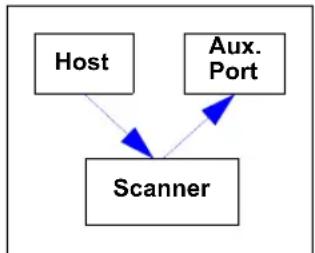
Half Duplex (Aux Port Mode)
Usage: Used to display symbol data on an auxiliary screen close to the scanner.
Definition: In Half Duplex mode all auxiliary port data and symbol data is sent directly to the host. Symbol data is displayed on the auxiliary port screen at the same time the data is sent to the host.
Data Initiated from the Auxiliary Port
Auxiliary port data to the host is ignored if the scanner is in a polled mode.
Auxiliary port data or scanned data is sent to the host whenever it is received.
Auxiliary port data is not echoed.
Auxiliary port data to the host is always sent without a preamble or a postamble.
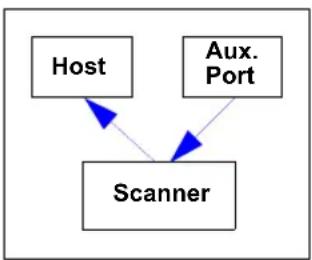
flowchart
graph TD
    A["Host"] --> C["Scanner"]
    B["Aux. Port"] --> C["Scanner"]
Data Initiated from the Scanner
Scan data is transmitted to the auxiliary port at the same time it is transmitted to the host.
Data transmission conforms with all parameters specified in the configuration menu (e.g., Preamble, Postamble, End of Read Cycle).
Data Initiated from the Host
All host data is echoed to the auxiliary port in unpolled mode.
flowchart
graph TD
    A["Host"] --> C["Scanner"]
    B["Aux. Port"] --> C["Scanner"]
flowchart
graph TD
    A["Host"] --> C["Scanner"]
    B["Aux. Port"] --> C["Scanner"]
Serial Cmd:
2 = Half Duplex
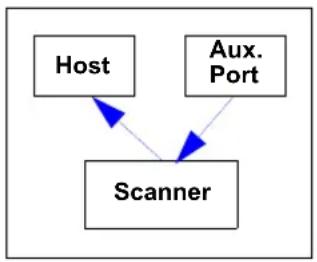
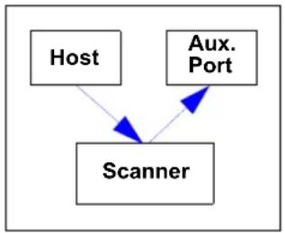
Full Duplex (Aux Port Mode)
Usage: Used when communication to and from the auxiliary port is required.
Definition: In Full Duplex mode all auxiliary port data and symbol data is sent directly to the host. Symbol data is not displayed on the auxiliary port screen.
Data Initiated from the Auxiliary Port
Auxiliary port data to the host is ignored if the scanner is in a polled mode.
Auxiliary port data or scanned data is sent to the host whenever it is received.
Auxiliary port data is not echoed.
Auxiliary port data to the host is always sent without a preamble or a postamble.
flowchart
graph TD
    A["Host"] --> C["Scanner"]
    B["Aux. Port"] --> C["Scanner"]
Data Initiated from the Scanner
Scan data is not sent to the auxiliary port.

flowchart
graph TD
    A["Host"] --> B["Scanner"]
    C["Aux. Port"] --> B
Data Initiated from the Host
All host data is echoed to the auxiliary port in unpolled mode.
flowchart
graph TD
    A["Host"] --> C["Scanner"]
    B["Aux. Port"] --> C["Scanner"]
Serial Cmd:
$$ 3 = \text { Full duplex } $$
Daisy Chain (Aux Port Mode)
Note: See also Daisy Chain Autoconfigure on page 3-19.
Usage: Used in applications where:
A symbol might be scanned in both ladder and picket fence directions.
A symbol may be present on multiple sides of a package.
Symbols are presented at different depths.
Definition: In a daisy chain application, scanners are connected in series or "daisy chain" and decoded data is relayed from one scanner to another on up to the host.
A master scanner has its host port linked to the host computer and its auxiliary port linked to the host port of the first secondary scanner in the chain. Thereafter, each secondary's auxiliary port is linked to the host port of the secondary that is further from the host in the daisy chain.
Each scanner in the daisy chain can be assigned an ID that accompanies any data that it sends.
Serial Cmd:
4 = Daisy Chain
Function: Before the master scanner times out, it checks its auxiliary port for data. It should be set to wait at least 20 ms for each secondary in the daisy chain. (See Read Cycle Timeout on page 4-16.) If no data is received within the read cycle timeout, the master sends a No Read message to the host. Otherwise the complete data is sent.
If for example the master scanner is set to timeout in 120 ms, the first secondary scanner downstream might be set to 100 ms, the next to 80 ms, and so forth, thus assuring that at least 20 ms elapses between transmissions. ^a
Daisy-chained scanners can send a series of symbols by enabling Multisymbol and a common multisymbol separator. If the master scanner does not receive the expected number of symbols, No Read messages are appended to the data string to make up the difference between the number of symbols enabled in Multisymbol and the number of symbols read.
For example, a master and two secondary scanners have Number of Symbols set to 3 and Multisymbol Separator defined as %. If the master and the first secondary scanner do not find symbols, but the next secondary scanner registers a good read, the transmitted results would be:
symbol data % No Read % No Read
a. The above example is based on the best case. Other factors such as baud rate, dynamic focus timing, number of characters in a given symbol, and the number of secondaries in the daisy chain can affect timing and may need to be included in your calculations for complete accuracy.
Daisy Chain (Aux Port Mode) (cont.)
Conditions: The conditions for a daisy chain application are as follows:
-
The master scanner's trigger must be Serial or External; the secondary scanners' triggers are configured for Serial.
-
All scanners are enabled to Daisy Chain mode.
-
Each scanner's auxiliary port must be connected to the Host port of its secondary scanner.
-
Each secondary scanner in the daisy chain must be set to send its data no less than 20ms before its preceding scanner.
-
All but the master scanner must have Postamble enabled and set to CR (^M) only.
-
All but the master scanner must have their No Read messages disabled.
-
If Multisymbol is enabled, Multisymbol Separator characters must match in all scanners and Number of Symbols must be set to number large enough to include all the symbols it may itself read plus the number of symbols that it will be expected to relay to the host or the next scanner up the line.
-
Symbology ID enable/disable must be the same in all scanners.
-
All but the master scanner must have their diagnostic warning messages disabled.
-
Daisy Chain ID Status enable/disable and the number of characters in Daisy Chain ID must be the same in all scanners.
Command Processing (Aux Port Mode)
Usage: Allows user to send configuration from the Host port or the Aux Port.
Definition: When enabled, Command Processing allows commands to be entered via the Aux Port. The following rules apply:
- Symbol data, including the serial trigger if used, will be transmitted to the last port from which a command was sent.
- If a reset occurs, all data will be transmitted to the host port.
Serial Cmd:
Options: 5 = Command Processing
Baud Rate (Aux Port)
Usage: Can be used to transfer data faster or match an auxiliary device.
Definition: The rate at which the scanner and host transfer data back and forth.
Serial Cmd:
Default: 9600
Options: 1 = 1200
$$ 2 = 2 4 0 0 $$
$$ 3 = 4 8 0 0 $$
$$ 4 = 9 6 0 0 $$
$$ 5 = 1 9. 2 \mathrm{K} $$
$$ 6 = 3 8. 4 \mathrm{K} $$
$$ 7 = 5 7. 6 \mathrm{K} $$
$$ 8 = 1 1 5. 2 \mathrm{K} $$
Parity (Aux Port)
Usage: Only changed if necessary to match host setting.
Definition: An error detection routine in which one data bit in each character is set to 1 or 0 so that the total number of 1 bits in the data field is even or odd.
Serial Cmd:
Default: Even
Options: 0 = None 1 = Even 2 = Odd
Stop Bits (Aux Port)
Usage: Only changed if necessary to match host setting.
Definition: Allows the user to select the last one or two bits in each character to indicate the end of the character.
Serial Cmd:
Default: One
Options: 0 = One 1 = Two
Auxiliary Port Protocol
Data Bits (Aux Port)
Usage: Only changed if necessary to match host setting.
Definition: Number of bits in each character.
Serial Cmd:
Default: Seven
Options: 0 = Seven 1 = Eight
Daisy Chain ID Status (Aux Port)
Note: Enable/disable and length must be the same in all scanners.
Usage: Used in a daisy chain setup in cases where the host needs to know which scanner in a daisy chain setup sent the data.
Definition: Each scanner in a daisy chain can be assigned a one or two character ID that will appear in front of decoded data and identify its source.
Serial Cmd:
Default: Disabled
Options: 0 = Disabled 1 = Enabled
Daisy Chain ID (Aux Port)
Note: All secondary scanners must be set to Serial for Daisy Chain to function.
See Trigger on page 4-5.
Usage: Used in a daisy chain setup in cases where the host needs to know which scanner sent the data.
Definition: A one or two character prefix which identifies the particular daisy chain scanner from which the data is being sent.
Serial Cmd:
Default: 1/
Options: Any one or two ASCII characters.
Daisy Chain Autoconfigure
Note: This command is not available in ESP.
Usage: For quick setup and configuration of the daisy chain network.
Definition: Daisy Chain Autoconfigure is issued to the master scanner in the daisy chain and the software responds as follows:
- Counts the number of secondary scanners in the daisy chain.
- Assigns an internal ID number (1...n) to each secondary scanner, where the first secondary scanner is number 1 (and its own ID being a 0).
- Propagates the communications settings and the relevant operating modes of the master scanner to the host and auxiliary ports of each secondary scanner.
- Resets each secondary scanner.
- Verifies that each secondary scanner has acquired the new settings.
Serial Cmd:
When setting up a daisy chain operation, follow these steps:
- Set the master (the scanner connected to the host) scanner to Serial.
This sets all the scanners in the daisy chain to Serial when the command is carried out.
Before Autoconfigure you must set the primary scanner to Serial (S):

flowchart
graph LR
    A["Host"] --> B["Primary Scanner"]
    B --> C["Secondary Scanner"]
    C --> D["Secondary Scanner"]
    B -->|S| B
    C -->|S| C
    D -->|S| D
- Send
command. - If necessary, set the master scanner to Edge.
After Autoconfigure you may set the primary scanner to Edge (S), but the other scanners must remain in Serial (S):

flowchart
graph LR
    A["Host"] --> B["Primary Scanner"]
    B --> C["Secondary Scanner"]
    C --> D["Secondary Scanner"]
    B -->|E| B
    C -->|S| C
    D -->|S| D
Daisy Chain Scanner ID
Note: Scanner IDs can also be assigned in Daisy Chain (Aux Port Mode) (page 3-14).
Usage: This command provides a convenient way to assign custom daisy chain IDs to specific scanners that were assigned during the daisy chain autoconfigure process.
Definition: Assigns a new daisy chain ID to a daisy chain secondary scanner. The command is sent to the master scanner to configure the other secondary scanners.
Scanner Number
Definition: Specifies the target scanner (by sequential number) which will be receiving the new daisy chain ID. The master scanner is always 0 (zero). All secondary scanners are numbered 1...n in the order that they are connected.
Note: These numbers are for assigning IDs only and are not changeable.
Serial Cmd:
Options: 1.....n (0 for the master scanner)
Scanner ID
Definition: A two-character user-defined ASCII message identifying a scanner in the daisy chain.
Serial Cmd:
Default: Sequential numbering of scanner units resulting from the Daisy Chain Autoconfigure
Options: Any two characters except NUL, <, >, or ,.
Note: See also Chapter 13, Output Format.
Note: After a secondary scanner accepts a new ID, it automatically invokes a reset-with-save command.
Auxiliary/Configuration Port System Data
Note: Do not use Auxiliary Port in a daisy chain operation.
Auxiliary Port Status
Note: This command only applies if Auxiliary Port Mode is set to Command Processing.
See Command Processing (Aux Port Mode) on page 3-16.
Usage: To check symbol data and error messages via the Aux Port.
Definition: When enabled, system data, including decoded data and diagnostic warning messages, will be routed to the Aux Port.
Serial Cmd:
Default: Disabled
Options: 0 = Disabled 1 = Enabled
Configuration Port Status
Usage: To check symbol data and error messages via the configuration port.
Definition: When enabled, system data, including decoded data and diagnostic warning messages, will be routed to the 9-pin configuration port.
Serial Cmd:
Default: Enabled
Options: 0 = Disabled
1 = Enabled
Important: Enable Data Out 9-Pin when using the configuration port.
Preamble
Preamble
Preamble Status
Usage: Used for identifying and controlling incoming data. For example, defining the preamble as a carriage return and a line feed causes each decoded message to be displayed on its own line.
Definition: Defines a one to four character data string that can be added to the front of the decoded data.
Serial Cmd:
Default: Disabled
Options: 0 = Disabled 1 = Enabled (within any protocol)
Preamble Character(s)
Serial Cmd:
Default: ^M corresponds to: carriage return/NUL/NUL/NUL.
Options: Up to four user-defined ASCII characters, including control characters.
Within a Serial Command
To enter control characters within a serial command, hold down the control key while typing the desired character.
Example:
Within an Embedded Menu
Control characters entered on the command line are displayed in the menu as mnemonic characters, such as:
To enter a control character from within an embedded menu, first type in a space (with the space key). This has the effect of allowing the control key to be recognized as a part of the control character. Next hold down the control key while typing the desired character.
Example: Space CTRL-m to enter ^M
Postamble
Postamble Status
Usage: Used for identifying and controlling incoming data. For example, defining the postamble as a carriage return and a line feed causes each decoded message to be displayed on its own line.
Definition: Defines a one- to four-character data string that can be added to the end of the decoded data.
Serial Cmd:
Default: Enabled
Options: 0 = Disabled 1 = Enabled
Postamble Character(s)
Serial Cmd:
Default: ^M^J corresponds to carriage return/line feed/NUL/NUL, as displayed in the menu.
Options: Up to four user-defined ASCII characters, including control characters.
Within a Serial Command
To enter control characters within a serial command, hold down the control key while typing the desired character.
Example:
Within an Embedded Menu
Control characters entered on the command line are displayed in the menu as mnemonic characters, such as:
To enter a control character from within an embedded menu, first type in a space (with the space key). This has the effect of allowing the control key to be recognized as a part of the control character. Next hold down the control key while typing the desired character.
Example: Space CTRL-m Space CTRL-j to enter ^M^J.
LRC Status
(Longitudinal Redundancy Check)
Usage: Used when extra data integrity is required.
Definition: An error-checking routine that verifies the accuracy of transmissions. It is the exclusive OR of all characters following the STX (start of text) up to and including the ETX (end of text). What this means is that the binary representation of all the characters in a transmissions are cumulatively added in a column and each resulting odd integer is assigned a 1 and each even integer a 0 (two 1s = 0, two 0s = 0, a 1 and a 0 = 1). The extra LRC character is then appended to the transmission and the receiver connected to the host port performs the same addition and compares the results.
Serial Cmd:
Default: Disabled
Options: 0 = Disabled 1 = Enabled
Intercharacter Delay
Usage: Used only when a host cannot receive data quickly enough and there is enough time between symbols to allow data to be completely transferred. It is rarely used since any setting other than zero will slow down communications. For example, a 200 setting will result in a 1/5 second delay between each character that is transmitted.
Definition: The time interval in milliseconds between individual characters transmitted from the scanner to the host.
Serial Cmd:
Default: 0
Options: 0 to 255 (in milliseconds)
Note: 0 causes no delay between characters.
Response Timeout
Response Timeout
Usage: Used only when a response is required from the host. While in Multidrop, if the scanner does not receive an ACK or NAK from the host after sending polled data, it will act on a fault. The scanner can be set to wait indefinitely by setting Response Timeout to zero.
Definition: Time the scanner will wait before timing out if ACK, NAK, and ETX are enabled, and a host response is expected.
Serial Cmd:
Default: 2 (x 10 = 20 ms)
Options: 0 to 255 in 10 ms increments (0 to 2.55 seconds) (A 0 setting causes an indefinite wait.)
41 Read Cycle
Contents
Read Cycle by ESP 4-2
Read Cycle Serial Commands 4-2
Multisymbol....4-3
Trigger 4-5
External Trigger State 4-11
Serial Trigger 4-12
Start Character (Non-Delimited) 4-13
Stop Character (Non-Delimited) 4-13
End of Read Cycle....4-14
Good Decode Reads 4-17
Gain Settings 4-18
Focus 4-19
Scan Speed 4-20
Automatic Gain Control (AGC) Settings 4-21
Maximum Element 4-22
Tracking Adjustment....4-23
After you've established communications and completed basic read rate testing, you will need to address the spatial and timing parameters associated with your application. In a typical operation, a bar-coded item moves along a line past a scanner. A trigger or timer activates a read cycle during which the scanner actively searches for symbols. You will need to decide how to initiate the read cycle and how and when to end it.
Note: When assigning characters in user-defined fields, the characters NUL, <, >, and, can only be entered through embedded menus, not through ESP or serial commands.
Note: You can learn the current setting of any parameter by inserting a question mark after the number, as in
Note on Serial Commands: To preserve continuity with other Microscan products, some serial configuration commands may include 0s or 1s as placeholders. In order for a these commands to be implemented, the parameter values or a comma must be included.
Read Cycle by ESP
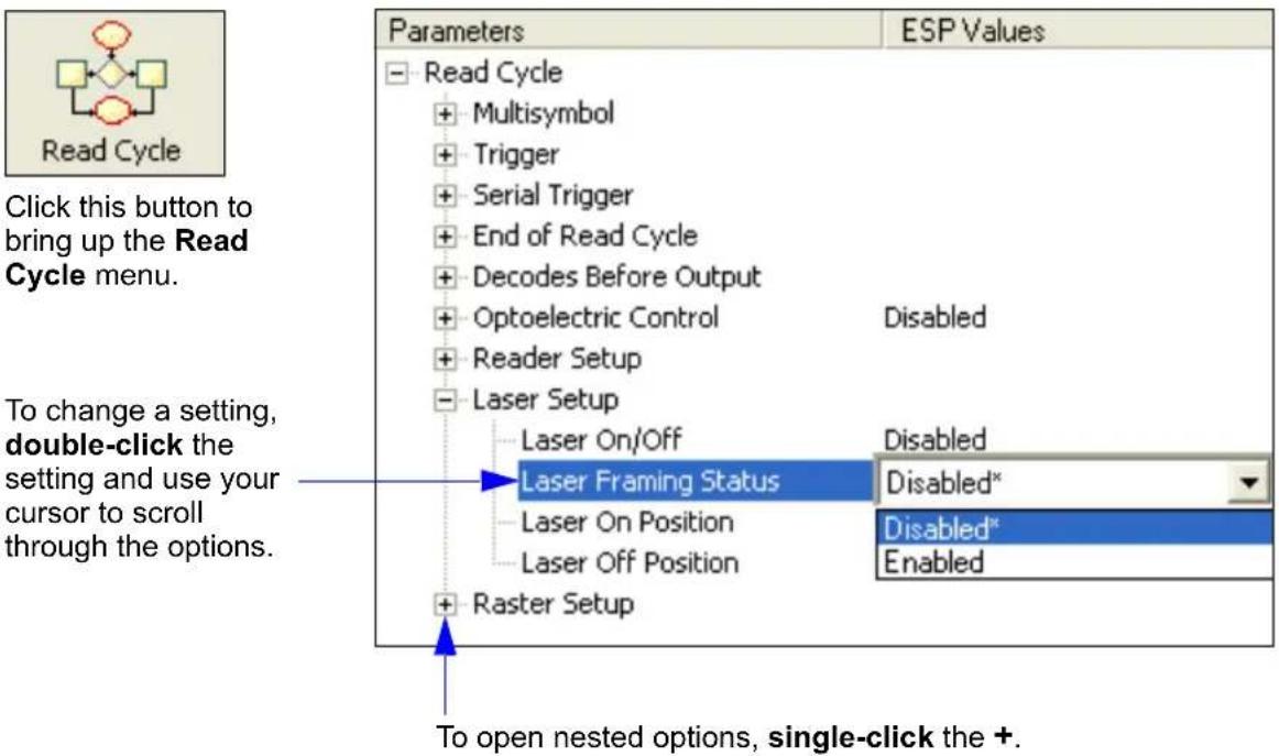
text_image
Read Cycle Click this button to bring up the Read Cycle menu. To change a setting, double-click the setting and use your cursor to scroll through the options. Parameters ESP Values Read Cycle + Multisymbol + Trigger + Serial Trigger + End of Read Cycle + Decodes Before Output + Optoelectric Control Disabled + Reader Setup - Laser Setup -Laser On/Off Disabled -Laser Framing Status Disabled* -Laser On Position Disabled* -Laser Off Position Enabled + Raster Setup To open nested options, single-click the +.Read Cycle Serial Commands
Command Title Command Format
| Trigger | |
| Serial Trigger Character | |
| External Trigger State | |
| End of Read Cycle | |
| Good Decode Reads | |
| Multisymbol | |
| Start Serial Trigger Character | |
| End Serial Trigger Character | |
| Scan Speed | |
| Maximum Element | |
| Gain Settings | |
| AGC Settings | |
| Focus | |
| Tracking Adjustment |
Multisymbol
Usage: Multisymbol is commonly used in shipping applications where a shipping symbol contains individual symbols for part number, quantity, etc. This feature allows one trigger to pick up all the symbols. AIAG and EAN-128 are two application standards that address this need.
Definition: Multisymbol allows the user to define up to 12 symbols that can be read in a single read cycle.
Conditions: The following conditions apply:
- Each symbol must be different to be read unless they appear in the scan line at the same time.
- The maximum number of characters in a read cycle is 32520 for all symbols.
- The maximum number of characters the scanner can transmit is calculated by: Preamble + maximum number of symbols * (aux id + symbology id + maximum symbol length + quality output + ((number of insertion cells x cell length) + separator) + postamble + LRC = 37425.
- All No Read messages are posted at the end of the data string.
- If more than one symbol is within the scan beam at the same time, symbol data may not be displayed in the order of appearance.
- If Matchcode Type is set to Sequential or if Trigger is set to Continuous Read 1 Output, Number of Symbols will default to 1 (if set to any number greater than 1).
Number of Symbols
Definition: Number of Symbols is the number of different symbols that can be read in a single read cycle.
Conditions: The following conditions apply:
- When Number of Symbols is set to Single, the read cycle ends when one symbol is decoded and output.
- When Number of Symbols is set to Multiple, all decoded symbol data (for both the same and different symbols) are output while the read cycle is active and/or no timeout has occurred.
Serial Cmd:
Default: 1
Options 1 to 12
Multisymbol
Multisymbol Separator
Usage: Used to delimit or separate data fields with a user defined character.
Definition: The character that's inserted between each symbol scanned when Multisymbol is set to any number greater than 1.
ESP: To select a new multisymbol separator, double-click on Separator and select a character in the popup window.

text_image
Parameters Read Cycle Multisymbol Number of Symbols 1 Multisymbol Separator Trigger Serial Trigger End of Read Cycle Decodes Before Output Optoelectric Control Reader Setup Laser Setup Raster Setup STX NUL SOH STX ETX EOT ENQ ACK BEL BS HT LF VT FF CR SO SI DC1 DC2 DC3 DC4 NAK SYN ETB CAN EM SUB ESC FS GS RS US SP Click 'Delete' to remove characters.Serial Cmd:
Note: If Multisymbol Separator has been changed to any character other than the default comma and you wish to re-define the separator as a comma, use ESP or the embedded menu.
Default: , (comma)
Options: Any available ASCII character, except NUL, <, >, and , .
Trigger
Trigger Mode
Note: When doing calibration or read rate testing, the current trigger setting will be disregarded.
Note: This command does not need to be followed by an command.
Definition: The type of trigger event that will initiate the read cycle.
Serial Cmd:
Default: Continuous Read
Options: 0 = Continuous Read
1 = Continuous Read 1 Output
2 = External Level
3 = External Edge
4 = Serial Data
Usage: Continuous Read is useful in testing symbol readability or scanner functions. It is not recommended for normal operations.
Definition: In Continuous Read, trigger input options are disabled, the scanner is always in the read cycle, and it will attempt to decode and output every scan crossing a symbol. When To Output and No Read options have no effect on Continuous Read.
Serial Cmd:
Trigger
Continuous Read 1 Output
Usage: Continuous Read 1 Output can be useful in applications where it is not feasible to use a trigger and all succeeding symbols contain different information. It is also effective in applications where the objects are hand-presented.
Definition: In Continuous Read 1 Output the scanner self-triggers whenever it decodes a new symbol or a timeout occurs.
If End Of Read Cycle is set to Timeout and the symbol doesn't change, the scanner will repeat the output at the end of each timeout period. For example, if Timeout is set to one second, the scanner sends the symbol data immediately and repeats the output at intervals of one second for as long as the symbol continues to be scanned.
If End Of Read Cycle is set to New Trigger, the scanner will send the current symbol data immediately, but send it only once. A new symbol appearing in the scanner's range will be read and sent immediately provided it is not identical to the previous symbol read.
Serial Cmd:
Caution: In automated environments, Continuous Read 1 Output is not recommended because there is no one to verify that a symbol was missed.
Note: If Trigger is set to Continuous Read 1 Output, Number of Symbols will default back to 1 (if set to any number greater than 1).
External Trigger Level
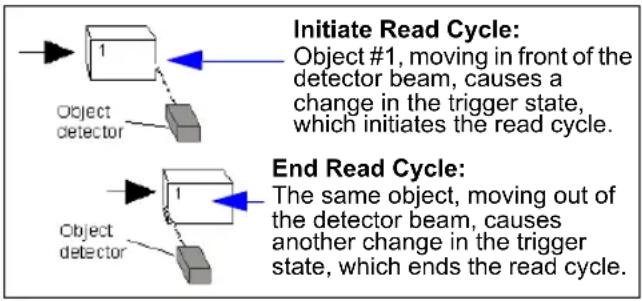
flowchart
graph TD
    A["Object detector"] --> B["1"]
    B --> C["Object detector"]
    D["Start"] --> E["Initiate Read Cycle: Object #1, moving in front of the detector beam, causes a change in the trigger state, which initiates the read cycle."]
    F["End"] --> G["End Read Cycle: The same object, moving out of the detector beam, causes another change in the trigger state, which ends the read cycle."]
Usage: This mode is effective in an application where the speeds of the conveying apparatus are variable and the time the scanner spends scanning each object is not predictable. It also allows the user to determine if a No Read has occurred.
Definition: External Level allows the read cycle to begin when a trigger (change of state) from an external sensing device is received. The read cycle endures until the object moves out of the sensor range and the active trigger state changes again.
Serial Cmd:
Important: Level and Edge apply to the active logic state (Open or Closed) that exists while the object is in a read cycle, between the rising edge and falling edge. Rising edge is the trigger signal associated with the appearance of an object. Falling edge is the trigger signal associated with the subsequent disappearance of the object.
Note: In External Trigger Level, sending a non-delimited start serial character will start a read cycle and sending a non-delimited stop serial character will end it. See Start Character (Non-Delimited) and Stop Character (Non-Delimited) on page 4-13.
Trigger
flowchart
graph TD
    A["Start"] --> B["Object detector 1"]
    B --> C["Initiate Read Cycle: Object #1, moving in front of the detector beam, causes a change in the trigger state, which initiates the read cycle."]
    D["Start"] --> E["Object detector 2"]
    E --> F["Initiate Second Read Cycle: Object #2, moving in front of the detector beam, causes another change in the trigger state. This signal initiates a new read cycle and ends the previous read cycle unless Timeout is enabled and a good read or timeout has not occurred."]
Usage: This mode is highly recommended in any application where conveying speed is constant or if spacing, object size, or timeouts are consistent.
Definition: External Trigger Edge, as with Level, allows the read cycle to begin when a trigger (change of state) from an external sensing device is received. However, the passing of an object out of sensor range does not end the read cycle. The read cycle ends with a good read output or, depending on End of Read Cycle setting, a timeout or new trigger occurs. External Trigger Edge, as with Level, allows the read cycle to begin when a trigger (change of state) from an external sensing device is received. However, the passing of an object out of sensor range does not end the read cycle. The read cycle ends with a good read or with a No Read when a No Decode Timeout occurs.
Serial Cmd:
Important: Level and Edge apply to the active logic state (Open or Closed) that exists while the object is in a read cycle, between the rising edge and falling edge. Rising edge is the trigger signal associated with the appearance of an object. Falling edge is the trigger signal associated with the subsequent disappearance of the object.
Note: In External Trigger Level, sending a non-delimited start serial character will start a read cycle and sending a non-delimited stop serial character will end it. See Start Character (Non-Delimited) and Stop Character (Non-Delimited) on page 4-13.
Serial Data
Usage: Serial Data is effective in a highly controlled environment where the host knows precisely when the object is in the scan zone. It is also useful in determining if a No Read has occurred.
Definition: In Serial Data, the scanner accepts an ASCII character from the host or controlling device as a trigger to start a read cycle. A Serial Data trigger behaves the same as an External Edge trigger.
Serial Cmd:
Serial Data and External Edge
Usage: Serial Data and External Edge is seldom used but can be useful in an application that primarily uses an external sensing device but occasionally needs to be manually triggered. An auxiliary terminal can be connected to the Aux Port so the user can send the serial trigger character through the scanner to the host.
Definition: In this mode the scanner accepts either a serial ASCII character or an external trigger pulse to start the read cycle.
Serial Cmd:
Trigger
Trigger Filter Duration
Usage: Trigger Filter Duration is useful where trigger bounce could cause false triggers.
Definition: Trigger Filter Duration can prevent trigger bounce from falsely triggering the scanner by limiting the time in which trigger pulses can be received.
Serial Cmd:
Default: 320 (10 ms)
Options: 0 to 65535 (0 to 2.047s in 31.25 s steps)
External Trigger State
Note: External Level, External Edge, or Serial Data and External Edge trigger mode must be enabled for External Trigger to take effect.
Usage: Users can select the trigger state that will operate with their systems. (If using an object detector, use Active Closed.)
Definition: When enabled for Active Closed the triggering device imposes a current on the optoisolator to activate the read cycle. When enabled for Active Open the triggering device interrupts the current to the optoisolator to activate the read cycle.
Serial Cmd:
Default: Active closed
Options: 0 = Active open 1 = Active closed
Serial Trigger
Serial Trigger
| Usage: | Useful in applications where a read cycle needs to be initiated and/or ended by user-defined serial characters. |
| Definition: | An online host command composed of a single ASCII host serial trigger character that initiates or ends the read cycle.Trigger characters are of two types: delimited and non-delimited. A delimited character is enclosed within angle bracket delimiters <> .A non-delimited trigger character is one that either starts or ends the read cycle and is NOT enclosed by delimiters such as <> . |
Rules for Trigger Modes
- In External Edge the scanner looks only for the Start Trigger Character and ignores any End Trigger Character that may be defined.
- In External Level, the Start Trigger Character begins the read cycle and an End Trigger Character ends it. Note that even after a symbol has been decoded and the data transmitted, the scanner remains in External Level trigger read cycle until a Stop character is received.
- In Serial Data and External Edge trigger mode, command, either a Start Trigger Character or a hardware trigger can start an Edge trigger read cycle.
Serial Trigger Character (Delimited)
Usage: Useful in applications where a single serial character enclosed in angle brackets initiates the read cycle.
Definition: A delimited trigger character is one that starts the read cycle, is enclosed by delimiters such as <>, and can only be sent when the trigger mode is set to Serial Data or Serial Data and External Edge.
Serial Cmd:
Default: ^] (corresponds to
Options: Any single ASCII character, including control characters, except NUL (00 in hex), an existing host command character, or an online protocol character. Control characters entered on the command line are displayed in the menu as mnemonic characters.
Note: Serial Data or Serial Data and External Edge triggering mode must be enabled for Serial Trigger Character to take effect.
Start Character (Non-Delimited)
Usage: Useful in applications where a different character is required to start a read cycle. Works with External Edge, External Level, and Serial Data and External Edge.
Definition: A single ASCII host serial trigger character that starts the read cycle and is not enclosed by delimiters such as < and >.
Serial Cmd:
Default: NUL (disabled)
Options: Two hex digits representing an ASCII character except <, >, XON, and XOFF.
Stop Character (Non-Delimited)
Usage: Useful in applications where a different character is required to end a read cycle. Works with External Level only.
Definition: A single ASCII host serial trigger character that ends the read cycle and is not enclosed by delimiters such as < and >.
Serial Cmd:
Default: NUL (disabled)
Options: Two hex digits representing an ASCII character except <, >, XON, and XOFF.
End of Read Cycle
Note: When to Output must be set to End of Read Cycle before this command can be active.
Definition: The read cycle is the time during which the scanner will attempt to read and decode a symbol. At the end of a read cycle the scanner stops reading symbols and sends the symbol data or No Read message to the host.
End of Read Cycle Mode
Definition: A read cycle can be terminated by a new trigger, a timeout, or a combination of both.
Serial Cmd:
Default: Timeout
Options: 0 = Timeout 1 = New Trigger 2 = Timeout and New Trigger
Note: When operating in Continuous Read or Continuous Read 1 Output, the scanner is always in the read cycle.
Timeout
Usage: Typically used with Serial or Edge and Continuous One.
It is effective in highly controlled applications when the maximum length of time between objects can be predicted. It assures that a read cycle ends before the next bar-coded object appears, giving the system extra time to decode and transmit the data to the host.
Definition: Timeout ends the read cycle when the time set in Read Cycle Timeout elapses or "times out."
If in Continuous Read 1 Output, a timeout initiates a new read cycle and allows the same symbol to be read again.
With either External Edge, Serial Data, or Serial Data and External Edge enabled, a timeout ends the read cycle and symbol data or a No Read message is sent to the host.
With External Level enabled, the read cycle does not end until the falling edge trigger or a timeout occurs. The next read cycle does not begin until the next rising edge trigger.
New Trigger
Usage: New Trigger is an effective way to end a read cycle when objects move past the scanner at irregular intervals (not timing-dependent).
Definition: New Trigger ends the current read cycle and initiates a new one when a new trigger occurs. New Trigger refers only to a "rising edge" trigger. With either External Edge, Serial, or Serial or Edge enabled, an edge or serial trigger ends a read cycle and initiates the next read cycle. In the case of External Level, a falling edge trigger ends the read cycle but the next read cycle does not begin until the occurrence of the next rising edge trigger.
Note: When New Trigger is enabled and if not in External Level mode, Laser On/Off will have no effect. When No Reads occur, the laser will remain on.
Timeout and New Trigger
Usage: Useful in applications that require an alternative way to end the read cycle. For example, if an assembly line should stop completely or the intervals between objects are highly irregular.
Definition: Timeout and New Trigger is identical to Timeout, except that a timeout or a new trigger (whichever occurs first) ends the read cycle.
End of Read Cycle
Read Cycle Timeout
Usage: Useful in many tightly controlled applications which require a read cycle to end before the next object appears and therefore need the flexibility of a timeout adjustment.
Definition: Read Cycle Timeout is the time span of the read cycle and is represented in 10 ms increments. It is used in conjunction with External Edge or Serial Trigger.
Serial Cmd:
Default: 100 (x 10 ms)
Options: 0 to 65535. (Divide any positive number entered by 100 to determine the time in seconds.)
Note: A minimum setting of 2 is recommended.
Note: Timeout or Timeout or New Trigger under End of Read Cycle must be enabled for Read Cycle Timeout to take effect.
Good Decode Reads
Usage: This is a very useful feature to increase reliability of reads for symbologies that do not have internal error checking such as Pharmacode.
Definition: The number of decodes (from 1 to 31) required per symbol before a symbol's decoded data is sent. It requires the scanner to successfully decode a symbol a designated number of times (not necessarily consecutively) before it is sent. If it doesn't achieve the number of good reads during the read cycle, then a No Read will be sent.
Note: Higher settings will decrease throughput speed.
Serial Cmd:
Default: 1
Options: 1 to 31
Good Decode Output Mode
Definition: Affects how the scanner counts symbols that it reads successfully.
Serial Cmd:
Default: Non-Consecutive
Options: 0 = Non-Consecutive 1 = Consecutive
Gain Settings
Gain Settings
The settings in this section are typically adjusted by Calibration, or by qualified technicians. They are included here for special applications. Before making changes to individual commands in this section, it would be advisable to make a written record of current settings.
Gain Adjustment
Usage: Can be useful for fine-tuning gain or when portions of analog signals spike as in the case of specular reflection or extraneous noise. Caution: Changes to Gain are typically done by qualified technicians in Calibration. See Chapter 9, Calibration.
Definition: Sets a voltage amplitude value for the analog circuitry.
Serial Cmd:
Default: Default is 40 (nominal). Gain is optimized at the factory before shipment; the default value may not be 40.
Options: 0 to 255
AGC Mode
Definition: Tracks peak signals and selects an amplitude reference point to sample the analog signals for converting to digital.
Serial Cmd:
Default: Disabled
Options: 0 = Disabled 1 = Enabled
Focus
Focus is generally set during the Calibration routine (see Chapter 9, Calibration). However, in certain applications involving specific focal lengths, manual control of focus may be appropriate.
Focus Position
Definition: Allows the user to change the focus position setting.
Serial Cmd:
Default: 0
Options: 0 to 40
Scan Speed
Scan Speed
Definition: Allows the user to set the number of scans per second by controlling the spinning mirror motor speed.
Serial Cmd:
Default: 400
Options: 400 to 1000
Automatic Gain Control (AGC) Settings
Important: AGC settings apply to both AGC and symbol detection.
Symbol Detect Status
Usage: During the read cycle, the scanner counts the number of bar and space transitions defined in the Transition Counter. If the count matches or exceeds the threshold, the scanner will perform AGC routines.
Definition: AGC is the acronym for Automatic Gain Control. AGC increases the depth of field by attempting to maintain signal strength at a constant level regardless of the range of the symbol.
Serial Cmd:
Default: Disabled
Options: 0 = Disabled 1 = Enabled
Minimum Number of Transitions
Usage: Can be useful in certain application where extraneous objects in the field of view might require a higher threshold.
Definition: Determines the number of bar/space transitions that must be read before a symbol is considered present and AGC can be resolved.
Serial Cmd:
Default: 14
Options: 1 to 255
Maximum Element
Maximum Element
Definition: Maximum Element represents the maximum bar element width that is allowed before a video reset occurs (default to white).
Caution: Do not change this parameter unless instructed by a Microscan representative.
Serial Cmd:
Default: 400 (x 0.01% of scan)
Options: 50 to 5000
Tracking Adjustment
Definition: Sets a tracking value for the scanner's analog circuitry. Changes to tracking adjustment should be made by Autocalibration.
Serial Cmd:
Default: 40
Options: 5 to 127
Tracking Adjustment
Symbologies
Contents
Symbologies by ESP....5-2
Symbologies Serial Commands 5-2
Code 39....5-3
Code 128 / EAN-128 5-6
Interleaved 2 of 5....5-10
Codabar....5-13
UPC/EAN 5-16
Code 93....5-19
Pharmacode 5-20
PDF417 5-22
Narrow Margins / Symbology ID....5-24
Background Color 5-26
Autodiscriminate 5-27
This section describes the various symbol types that can be read and decoded by the scanner.
Code 39 is enabled by default. To enable all symbologies, right-click Autodiscrimination under Symbol Type in the Utilities menu and select Enable, or send a
serial command to the scanner from the Terminal window.
Note: The characters NUL, <, >, and , can only be entered through embedded menus, not through ESP or serial commands.
Symbologies by ESP
Symbologies by ESP
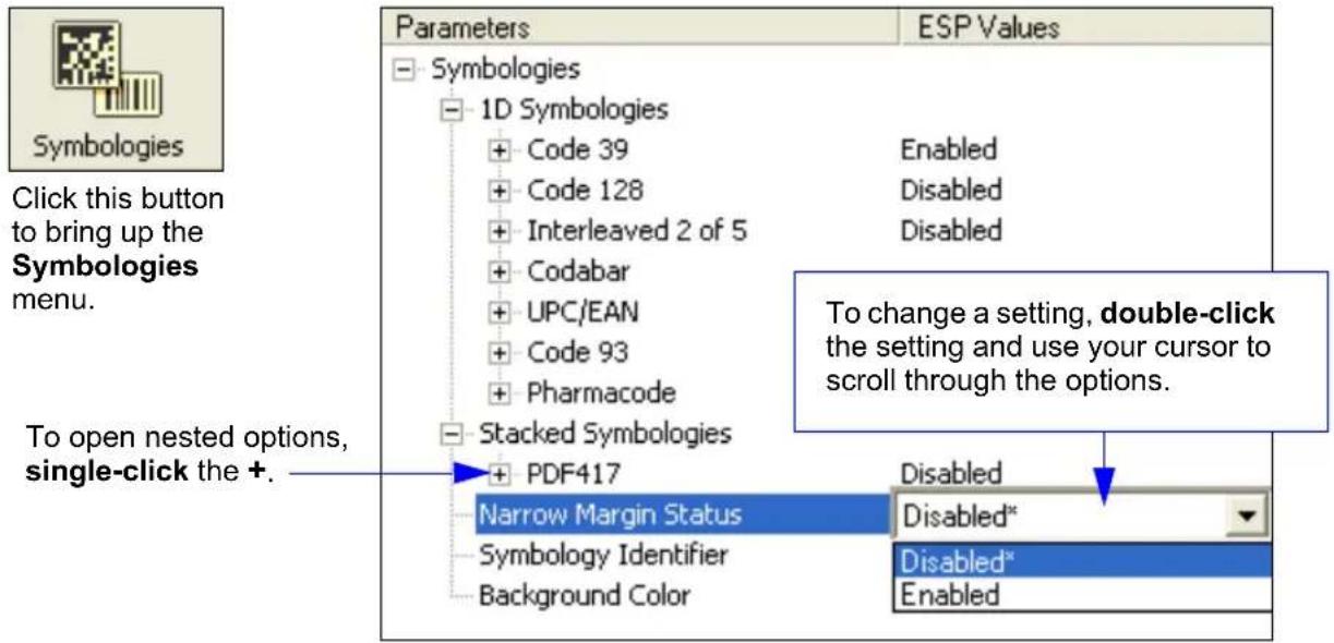
text_image
Symbologies Click this button to bring up the Symbologies menu. To open nested options, single-click the +. Parameters ESP Values Symbologies 1D Symbologies + Code 39 Enabled + Code 128 Disabled + Interleaved 2 of 5 Disabled + Codabar + UPC/EAN + Code 93 + Pharmacode Stacked Symbologies + PDF417 Narrow Margin Status Disabled* Symbology Identifier Disabled* Background Color EnabledSymbologies Serial Commands
Command Title Command Format
| Narrow Margins/Symbology ID | |
| Background Color | |
| Code 39 | |
| Codabar | |
| Interleaved 2 of 5 | |
| UPC/EAN | |
| Code 128/EAN-128 | |
| Code 93 | |
| PDF417 | |
| Pharmacode |
Code 39
Usage: Code 39 is considered the standard for non-retail applications.
Definition: An alphanumeric symbol with unique start/stop symbol patterns, composed of 9 black and white elements per character, of which 3 are wide.
Code 39 Status
Serial Cmd:
Default: Enabled
Note: This is the only symbol type enabled by default.
Options: 0 = Disabled 1 = Enabled
Check Character Status (Code 39)
Serial Cmd:
Default: Disabled
Options: 0 = Disabled 1 = Enabled
Check Character Output (Code 39)
Usage: Check Character Output Status, added to the symbol, provides additional security.
Definition: When enabled, the check character is read and sent along with the symbol data. When disabled, symbol data is sent without the check character.
Note: With Check Character Output Status and an External or Serial trigger option enabled, an invalid check character calculation will cause a No Read message to be transmitted at the end of the read cycle.
Serial Cmd:
Default: Disabled
Options: 0 = Disabled 1 = Enabled
Large Intercharacter Gap (Code 39)
Usage: Large Intercharacter Gap is helpful for reading symbols that are printed out of specification.
Caution: Do not use Large Intercharacter Gap with Narrow Margins enabled since a large intercharacter gap (over 3x) could cause a narrow margins (5x) to be interpreted as an intercharacter gap.
Definition: When enabled, the scanner can read symbols with gaps between symbol characters that exceed three times (3x) the narrow element width.
Serial Cmd:
Default: Disabled
Options: 0 = Disabled 1 = Enabled
Fixed Symbol Length Status (Code 39)
Usage: Helps prevent truncations and increases data integrity by ensuring that only a fixed symbol length will be accepted.
Definition: When enabled, the scanner will check the symbol length against the symbol length field. If disabled, any length is considered a valid symbol.
Serial Cmd:
Default: Disabled
Options: 0 = Disabled 1 = Enabled
Symbol Length (Code 39)
Definition: Specifies the exact number of characters that the scanner will recognize (this does not include start and stop and check character characters). The scanner ignores any symbol not having the specified length.
Serial Cmd:
Default: 10
Default: 1 to 128
Full ASCII Set (Code 39)
Usage: Must be enabled when reading characters outside the standard character set (0-9, A-Z, etc.)
User must know in advance whether or not to use Full ASCII Set option. Since Full ASCII Set requires two symbol words to encode one character, it is less efficient.
Definition: Standard Code 39 encodes 43 characters; zero through nine, capital "A" through capital "Z", minus symbol, plus symbol, forward slash, space, decimal point, dollar sign and percent symbol. When Full ASCII Set is enabled, the scanner can read the full ASCII character set, from 0 to 255.
Serial Cmd:
Default: Disabled
Options: 0 = Disabled 1 = Enabled
Code 128/EAN-128
Usage: Code 128/EAN-128 is a smaller symbology, and is useful in applications with tight spots and high security needs.
Definition: A very dense alphanumeric symbology. It encodes all 128 ASCII characters; it is continuous, has variable length, and uses multiple element widths measured edge to edge.
Code 128 Status
Serial Cmd:
Default: Disabled
Options: 0 = Disabled 1 = Enabled (Serial Standard) 2 = Edge 3 = Serial Standard and Edge
Note: Code 128 must be Enabled for EAN-128 to function.
Fixed Symbol Length Status (Code 128)
Definition: When enabled, the scanner will check the symbol length against the symbol length field. When disabled, any length is considered a valid symbol.
Serial Cmd:
Default: Disabled
Options: 0 = Disabled 1 = Enabled
Symbol Length (Code 128)
Usage: Fixed Symbol Length helps prevent truncations and increases data integrity by ensuring that only one symbol length will be accepted.
Definition: Specifies the exact number of characters that the scanner will recognize (this does not include start and stop and check characters). The scanner ignores any symbol not having the specified length.
Serial Cmd:
Default: 10
Options: 1 to 128
Note: Fixed Symbol Length Status must be enabled for Symbol Length to take effect.
EAN-128 Status
Usage: Sometimes called the “shipping code,” it is used as a standard to track a product from site to site with a single symbol that contains categories of information identifiable across industries worldwide.
Definition: A subset of Code 128, with extended features using application identifiers to define the meaning and format of fields that immediately follow them. For more information, refer to the AIM website at:
http://www.aimglobal.org/standards/aimpubs.asp
Serial Cmd:
Note: Code 128 serial command fields for K474 precede EAN-128.
Default: Disabled
Options: 0 = Disabled 1 = Enabled 2 = Required
If set to Enabled, symbols can be read with or without a function 1 character in the first position.
If set to Required, the symbol must have a function 1 in the first position and conform to EAN format in order to decode the symbol.
Note: Code 128 must also be Enabled for EAN-128 to function.
Output Format (EAN-128)
| Usage: | Application Record is useful in applications in which the software can use application record formatting to help automate the processing of its EAN-128 data. |
| Definition: | Offers an option between Standard EAN-128 and Application Record format. |
| Serial Cmd: |
Default: Standard
| Options: 0 = Standard |
| 1 = Application Record |
| Standard: | When set to Standard, EAN-128 application identifiers and data fields are sent, but none of the formatting (separators, parentheses, padding) will be included. |
| Application Record: | Application Record is a variation of EAN-128 that allows the user to define separators between data fields, enclose application identifiers in parentheses, and enable padding (zeros) for variable length fields. |
Note: If an illegal Application Record format is detected, the scanner will process it as a No Read and output a No Read message (if enabled).
Application Record Separator Status (EAN-128)
Definition: When enabled, a separator character is inserted between application records.
Serial Cmd:
Default: Disabled
Options: 0 = Disabled 1 = Enabled
Application Record Separator Character (EAN-128)
Definition: Defines an ASCII character as an application record separator.
Serial Cmd:
Default: , (comma)
Options: User Defined ASCII character
Note: Output Format must be set to Application Record before this parameter can take effect.
Application Record Brackets Status (EAN-128)
Definition: When enabled, parentheses ( ) are added to enclose application identifiers.
Serial Cmd:
Default: Disabled
Options: 0 = Disabled 1 = Enabled
Note: Output Format must be set to Application Record before this parameter can take effect.
Application Record Padding Status (EAN-128)
Definition: Padding is the insertion of zeros to make up the maximum length of a variable application record data field, except for the last field which does not require padding.
When enabled, padding is included. When disabled, padding is omitted.
Note: Padding is never added to fixed length fields or to the last data field of a symbol. Enabling or disabling Record Padding will have no effect on these.
Serial Cmd:
Default: Disabled
Options: 0 = Disabled 1 = Enabled
Note: Output Format must be set to Application Record before this parameter can take effect.
Minimum Ratio Distance (Code 128)
Definition: Determines the error tolerance level.
Normal enforces a requirement for normal error tolerance.
High enforces a requirement for high element-to-element quality.
Highest enforces a requirement for very high element-to-element quality.
Serial Cmd:
Default: Normal
Options: 0 = Normal 1 = High 2 = Highest
Interleaved 2 of 5
Usage: Interleaved 2 of 5 has been popular because it is the most dense symbol for printing numeric characters less than 10 characters in length; however, Microscan does not recommend this symbology for any new applications because of inherent problems (truncation, for example).
Definition: A dense, continuous, self-checking, numeric symbology. Characters are paired together so that each character has five elements, two wide and three narrow, representing numbers 0 through 9, with the bars representing the first character and the interleaved spaces representing the second character. (A check digit is highly recommended.)
Important: You must set Symbol Length in order to decode I 2/5 symbols.
Interleaved 2 of 5 Status
Serial Cmd:
Default: Disabled
Options: 0 = Disabled 1 = Enabled
Check Digit Status (Interleaved 2 of 5)
Usage: Typically not used but can be enabled for additional security in applications where the host requires redundant check digit verification.
Definition: An error correcting routine in which the check digit character is added.
Serial Cmd:
Default: Disabled
Options: 0 = Disabled 1 = Enabled
Check Digit Output Status (Interleaved 2 of 5)
Definition: When enabled, a check digit character is sent along with the bar symbol data for added data security.
Serial Cmd:
Default: Disabled
Options: 0 = Disabled 1 = Enabled
Symbol Length #1 (Interleaved 2 of 5)
Usage: With I–2/5, two symbol lengths can be defined. When using only one symbol length in an application, setting Symbol Length #2 to 0 (zero) to ensure data integrity is recommended.
Definition: Allows user to define the symbol length. Because I–2/5 is a continuous symbology, it is prone to substitution errors. Hence, a symbol length must be defined and a symbol must contain an even number of digits.
Note: If start, stop or check digits are used, they are not included in the symbol length count.
Serial Cmd:
Default: 10
Options: 0 to 128, even
Note: Since I 2/5 characters are paired, symbol length must be set to an even number. If Check Digit is enabled, add 2 to your symbol length. For example, if your symbol is 10 characters plus a check digit, then enable Symbol Length for 12.
Note: Typically, when printing an I 2/5 symbol with an odd number of digits, a 0 will be added as the first character. Note: If both Symbol Length #1 and Symbol Length #2 are set to 0, then I-2 of 5 will be variable.
Symbol Length #2 (Interleaved 2 of 5)
Usage: If using a second symbol, a zero or any even symbol length from 2 to 64 may be specified. If not using a second symbol, set Symbol Length #2 to 0 to ensure data integrity.
Definition: Allows user to define a second symbol length for 1–2/5.
Serial Cmd:
Default: 6
Options: 0 to 128, even
Since I 2/5 characters are paired, symbol length must be set to an even number. If Check Digit is enabled, add 2 to your symbol length. For example, if your symbol is 10 characters plus a check digit, then enable Symbol Length for 12.
Note: Typically, when printing an I 2/5 symbol with an odd number of digits, a 0 will be added as the first character.
Note: If both Symbol Length #1 and Symbol Length #2 are set to 0, then I-2 of 5 will be variable.
Guard Bar (Interleaved 2 of 5)
Note: Whenever Guard Bar is enabled, the presence of guard bars is required for decoding to take place.
Usage: Useful when I 2 of 5 multisymbols are enabled to prevent false data output. This typically occurs with highly tilted or skewed symbols.
Definition: A guard bar is a heavy bar, at least 2 times the width of the wide bar, surrounding the printed 12 of 5 symbol and helping to prevent false reads.
Serial Cmd:
Default: Disabled
Options: 0 = Disabled 1 = Enabled
Range Mode (Interleaved 2 of 5)
Note: Whenever Guard Bar is enabled, the presence of guard bars is required for decoding to take place.
Definition: When enabled, this feature causes symbol length # 1 and symbol length # 2 to form of a range of lengths that can be decoded.
For example, if symbol lengths of 10 and 6 are enabled, those are the lengths that can be decoded. Note that either length can serve as the minimum or maximum.
Serial Cmd:
Default: Disabled
Options: 0 = Disabled 1 = Enabled
Codabar
Usage: Used in photo-finishing and library applications. Used in some medical applications at one time, but not typically used in newer applications. Definition: Codabar is a 16-character set (0 through 9, and the characters \$, :, /, ., +, and -) with start/stop codes and at least two distinctly different bar widths.
Codabar Status
Serial Cmd:
Default: Disabled
Options: 0 = Disabled 1 = Enabled
Start and Stop Match Status (Codabar)
Usage: Used to increase security of symbology.
Definition: Requires the Codabar start and stop characters (a, b, c, or d) to match before a valid read can occur.
Serial Cmd:
Default: Enabled
Options: 0 = Disabled 1 = Enabled
Start and Stop Output Status (Codabar)
Usage: Used to verify matching.
Definition: Causes the start and stop characters to be transmitted with symbol data.
Serial Cmd:
Default: Enabled
Options: 0 = Disabled 1 = Enabled
Codabar
Large Intercharacter Gap (Codabar)
Usage: It is helpful for reading symbols that are printed out of specification.
Caution: Do not use Large Intercharacter Gap with Narrow Margins enabled since enabling Large Intercharacter Gap (over 3x) could cause a narrow margins (5x) to be interpreted as an intercharacter gap.
Definition: Instructs the scanner to read symbols with gaps between characters exceeding three times the narrow element width.
Serial Cmd:
Default: Disabled
Options: 0 = Disabled 1 = Enabled
Fixed Symbol Length Status (Codabar)
Usage: Fixed Symbol Length helps prevent truncations and increases data integrity by ensuring that only one symbol length will be accepted.
Definition: When enabled, the scanner will check the symbol length against the fixed symbol length field. When disabled, any length would be considered a valid symbol.
Serial Cmd:
Default: Disabled
Options: 0 = Disabled 1 = Enabled
Symbol Length (Codabar)
Definition: Specifies the exact number of characters that the scanner will recognize (this does not include start and stop and check character characters). The scanner ignores any symbol not having the specified length.
Serial Cmd:
Default: 10
Options: 1 to 128
Note: Fixed Symbol Length Status must be enabled for Symbol Length to take effect.
Note: Because of symbology limitations, setting Symbol Length to any number less than four will produce undetermined results.
Check Character Type (Codabar)
Definition: Allows the user to select the check character type Codabar will use.
Serial Cmd:
Default: Disabled
Options: 0 = Disabled
1 = Modulus 16
2 = NW 7
3 = Both
Modulus 16: Used in the photo-finishing market.
NW 7: Used in Japanese markets.
Check Character Output Status (Codabar)
Usage: For additional security a check character can be added to the symbol.
Definition: When enabled, the check character character is sent along with the symbol data. When disabled, symbol data is sent without the check character.
Serial Cmd:
Default: Disabled
Options: 0 = Disabled 1 = Enabled
UPC/EAN
UPC/EAN
Usage: Used primarily in POS application in the retail industry. It is commonly used in applications in combination with Matchcode when there is a need to verify that the right product is being placed in the right packaging.
Definition: UPC (Universal Product Code) is a fixed length numeric, continuous symbology. UPC can have two- or five-digit supplemental symbol data following the normal symbol. The U.P.C., Version A (UPC-A) symbol is used to encode a 12 digit number. The first digit is the number system character, the next five are the manufacturer number, the next five are the product number, and the last digit is the checksum character.
When enabled, the scanner will read UPC-A and UPC-E only.
UPC Status
Serial Cmd:
Default: Disabled
Options: 0 = Disabled 1 = Enabled
EAN Status
Usage: UPC/EAN is the European version of the UPC symbology and is used in European market applications.
Note: UPC must be enabled for EAN to take effect.
Definition: EAN is a subset of UPC. When enabled, the scanner will read UPC version A, UPC version E, EAN 13, and EAN 8. It also appends a leading zero to UPC version A symbol information and transmits 13 digits. If transmitting 13 digits when reading UPC version A symbols is not desired, disable UPC/EAN.
Note: The extra character identifies the country of origin.
Serial Cmd:
Default: Disabled
Options: 0 = Disabled 1 = Enabled
Supplemental Status (UPC/EAN)
Usage: Reads Supplementals typically used in publications and documentation.
Definition: A supplemental is a 2 or 5 digit symbol appended to the main symbol.
When set to Enabled or Required, the scanner reads supplemental symbol data that has been appended to the standard UPC or EAN codes.
Serial Cmd:
Default: Disabled
Options: 0 = Disabled
1 = Enabled
2 = Required
Disabled: UPC Supplementals will not be decoded.
Enabled: When enabled, the scanner will try to decode a main and a supplemental.
However, if a supplemental is not decoded, at the end of the read cycle, the main will be sent by itself. The UPC main and supplemental symbols are considered to be one symbol and will be treated as such.
Required: When set to Required and either the main or supplemental symbol is not read, a single No Read condition results. The UPC main and supplemental symbols are treated as one symbol.
For example, if Supplementals is set to Required, Separator is enabled, and an asterisk is defined as the UPC separator character, then the data will be displayed as: MAIN * SUPPLEMENTAL.
Note: Under no circumstances will supplemental symbol data be sent without a main symbol.
Note: If additional symbols—other than the main or supplemental—will be read in the same read cycle, Number of Symbols should be set accordingly.
Separator Status (UPC/EAN)
Usage: Allows user to distinguish between the main and Supplemental symbols.
Definition: Allows the user to insert a character between the standard UPC or UPC/EAN symbol and the supplemental symbol when Supplementals is set to Enabled or Required.
Serial Cmd:
Default: Disabled
Options: 0 = Disabled 1 = Enabled
UPC/EAN
Separator Character (UPC/EAN)
Note: If Separator Character has been changed to any other character and you wish to redefine the separator as a comma, you will need to use ESP or the embedded menu.
Note: Whenever Separator Character is defined as a comma (,) sending a
Usage: As required by the application.
Definition: Allows the user to change the separator character from a comma to a new character.
Serial Cmd:
Default: , (comma)
Options: Any ASCII character
Supplemental Type (UPC/EAN)
Usage: As required by symbology used in application.
Definition: Allows the user to select 2 character or 5 character supplement, or both.
Serial Cmd:
Default: Both
Options: 0 = Both
1 = 2 characters only
2 = 5 characters only
Both: Either 2 character or 5 character supplementals will be considered valid.
2 Char Only: Only two character supplementals will be considered valid.
5 Char Only: Only five character supplementals will be considered valid.
Code 93
Usage: Used occasionally in the clinical industry.
Definition: Code 93 is a variable length, continuous symbology employing four element widths. Each Code 93 character has nine modules that may be either black or white. Each character contains three bars and three spaces.
Code 93 Status
Serial Cmd:
Default: Disabled
Options: 0 = Disabled 1 = Enabled
Fixed Symbol Length Status (Code 93)
Usage: Helps prevent truncations and increases data integrity by ensuring that only one symbol length will be accepted.
Definition: When enabled, the scanner will check the symbol length against the symbol length field. When disabled, any length is considered a valid symbol.
Serial Cmd:
Default: Disabled
Options: 0 = Disabled 1 = Enabled
Fixed Symbol Length (Code 93)
Definition: Specifies the exact number of characters that the scanner will recognize (this does not include start and stop and check characters). The scanner ignores any symbol not having the specified length.
Serial Cmd:
Default: 10
Options: 1 to 128
Pharmacode
Pharmacode
Usage: Pharmacode is used mostly with packaging for the pharmaceuticals industry.
Definition: The symbol encodes up to five different numbers, each with its own color which may be entered in decimal or "binary" format with a 1 represented by a thick bar and a 0 represented by a thin bar. Bar width is independent of height.
In decimal format, each part can be up to 999999.
In binary format, each input have up to 19 ones and zeros.
Note: It is recommended that you disable AGC before enabling Pharmacode.
Pharmacode Status
Serial Cmd:
Default: Disabled
Options: 0 = Disabled 1 = Enabled
Fixed Symbol Length Status (Pharmacode)
Serial Cmd:
Default: Disabled
Options: 0 = Disabled 1 = Enabled
Fixed Symbol Length (Pharmacode)
Serial Cmd:
Default: 10
Options: 4 to 16
Minimum Number of Bars (Pharmacode)
Serial Cmd:
Default: 4
Options: 4 to 16
Bar Widths (Pharmacode)
Serial Cmd:
Default: Mixed
Options: 0 = Mixed
1 = Narrow
2 = Wide
Decode Direction (Pharmacode)
Definition: Specifies the direction that a bar can be read.
Serial Cmd:
Default: Forward
Options: 0 = Forward 1 = Reverse
Fixed Threshold Value (Pharmacode)
Serial Cmd:
Default: 400
Options: 1 to 65535
PDF417
Note: Calibration does not function with PDF417 symbols. However, you can substitute a Code 128 symbol with the same mil size as your PDF417. When you do this, enable Code 128 and disable Raster scanning. After calibration, switch back to PDF417 and Raster scanning.
Usage: Used in applications where a large amount of information (over 32 characters) needs to be encoded within a symbol, typically where the symbol is transported from one facility to another. For example, an automobile assembly line might use a single symbol with multiple fields of information that will be read at several stations along the way, without reference to a database.
Definition: A two-dimensional, multi-row (3 to 90), continuous, variable length symbology that has high data capacity for storing up to 2700 numeric characters, 1,800 printable ASCII characters, or 1100 binary character per symbol. Each symbol character consists of 4 bars and 4 spaces in a 17-module structure.
PDF417 Status
Serial Cmd:
Default: Disabled
Options: 0 = Disabled 1 = Enabled
Raster Sweeps Before Decode Attempt (PDF417)
Usage: Might be useful in dynamic applications where symbols are close together and need to be decoded more quickly than the default setting allows.
Definition: Specifies the number of raster sweeps the scanner will execute on PDF symbols before decoding. A value of 0 effectively disables this feature, which allows the decoder to make a “best guess” as to when enough symbol words have been captured.
Serial Cmd:
Default: 0 (disabled)
Options: 0 to 4
Fixed Symbol Length Status (PDF417)
Usage: Used to increase data integrity by ensuring that only one symbol length will be accepted.
Definition: When enabled, the PDF symbol must contain the same number of characters as the symbol length setting before it can be considered a good decode. The scanner will ignore any symbol not having the specified length.
Serial Cmd:
Default: Disabled
Options: 0 = Disabled
1 = Enabled
Fixed Symbol Length (PDF417)
Definition: Specifies the exact number of characters the scanner will recognize.
Serial Cmd:
Default: 10
Options: 1 to 2710
Note: Fixed Symbol Length Status must be enabled for Fixed Symbol Length to take effect.
Decode at End of Read (PDF417)
Definition: Allows the user to specify that the decoding of the PDF417 symbol take place after the requirements of End of Read Cycle have been satisfied. This means that the scanner will accumulate information about the PDF417 candidate symbol but will not attempt to error-correct or translate the information until the end of the read cycle.
Serial Cmd:
Default: Disabled
Options: 0 = Disabled
1 = Enabled
Narrow Margins/Symbology ID
Usage: Used when the leading and trailing edges of the symbols are smaller than the standard margin or when other objects encroach into the margins. Definition: Allows the scanner to read symbols with quiet zones less than 8 times the width of the narrow bar element. The “quiet zone” is the space at the leading and trailing ends of a symbol. Each quiet zone can be as narrow as only five times the width of the narrow bar element when Narrow Margins is enabled.
Serial Cmd:
Default: Disabled
Options: 0 = Disabled 1 = Enabled
Note: Do not use Narrow Margins with Large Intercharacter Gap enabled in Code 39 or Codabar.
Symbology ID
Usage: Used when the symbology type and how it's decoded needs to be known.
Definition: Symbology ID is an AIM standard prefix set of characters that identify the symbol type.
When enabled, the scanner analyzes and identifies the symbology and adds a three character identifying prefix to the data:
- ] (close bracket character) indicating the presence of a symbology ID
-
A, C, E, I, L, Q, b, d, p, P, M A = Code 39, C = Code 128 or EAN-128, E = UPC/EAN,
I = I-2/5, F = Codabar; G = Code 93, L = PDF417, a = Pharmacode,
e = Composite/RSS, L = PDF417 and Micro PDF417 -
Modifier (see Explanation of Modifiers below)
Serial Cmd:
Default: Disabled
Options: 0 = Disabled 1 = Enabled
Explanation of Modifiers for Code 39, Codabar, and Interleaved 2/5
- For Code 39, Codabar and I–2/5, the modifier indicates Check Character and Check Character Output Status.
- For Code 39 only, Full ASCII needs to be enabled to see modifiers 4, 5, and 7.
| Modifier Check Character | Check Character Output | Full ASCII conversion performed (Code 39 only) |
| 0 Disabled N/A No | ||
| 1 Enabled Enabled No | ||
| 3 Enabled Disabled No | ||
| 4 Disabled N/A Yes | ||
| 5 Enabled Enabled Yes | ||
| 7 Enabled Disabled Yes |
Example:]A5 indicates a Code 39 symbol with Check Character and Check Character Output Status enabled and Full ASCII conversion performed.
Explanation of Modifiers for Other Symbologies
- For Code 128, a 1 indicates EAN-128; otherwise the modifier is a 0.
- For all other codes, the modifier is 0.
Background Color
Background Color
Usage: If the background is darker than the symbol, then enable black background. Typically the background is white; but on PCBs for example, they can be black.
Definition: Allows the user to choose which symbol background (white or black) the scanner can read.
Serial Cmd:
Default: White
Options: 0 = White 1 = Black
Autodiscriminate
Although Autodiscriminate is not a configuration command, but it is included here as a convenient tool for enabling most symbol types.
Usage: Commonly used for quick setup mode to detect symbol type. This is particularly useful for users who might be unfamiliar with their application's symbology.
Note: It does not alter individual fields such as Start/Stop, Fixed Length, etc. These need to be setup individually.
Definition: Enables all available symbology types except PDF417, UPC/EAN, and Pharmacode. The user may also individually disable/enable each symbology type.
Serial Cmd:
Default: Code 39 (only)
Options:
Enables all codes except noted above.
Enables Code 39 only
Enables I 2/5 only
Note: If using an I 2/5 symbol, verify that the number of characters in the symbol being scanned matches the symbol length enabled for the I 2/5 symbol type (default is 10 and 6).
Autodiscriminate
[6] I/O Parameters
Contents
I/O Parameters by ESP 6-2
I/O Parameters Serial Commands 6-3
Symbol Data Output....6-4
No Read Message 6-6
Bad Symbol Message 6-7
No Symbol Message....6-7
Read Duration Output 6-8
Output Indicators....6-9
Beeper....6-12
Serial Verification 6-13
EZ Button 6-15
EZ Button Modes 6-17
Input 1....6-19
Configurable Output 1....6-20
Trend Analysis Output 1....6-24
Diagnostics Output 1....6-27
Configurable Output 2....6-28
Trend Analysis Output 2....6-28
Diagnostics Output 2....6-28
Configurable Output 3....6-29
Trend Analysis Output 3....6-29
Diagnostics Output 3....6-29
Database Identifier Output 6-30
Quality Output 6-31
This section includes instructions on setting up conditions for changing input/output electrical transitions for control of the scanner's internal and external devices.
Note: The characters NUL, <, >, and , can only be entered through embedded menus, not through ESP or serial commands.
I/O Parameters by ESP
I/O Parameters by ESP
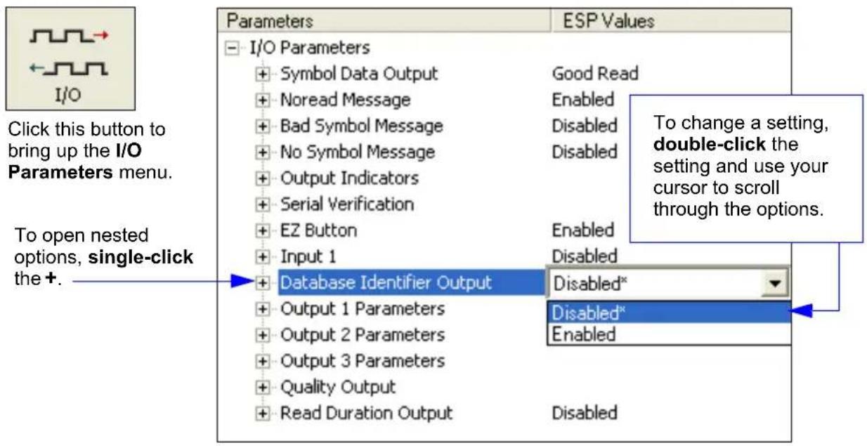
text_image
Parameters ESP Values I/O Parameters + Symbol Data Output Good Read + Noread Message Enabled + Bad Symbol Message Disabled + No Symbol Message Disabled + Output Indicators + Serial Verification + EZ Button Enabled + Input 1 Disabled Database Identifier Output Disabled* Output 1 Parameters Disabled* Output 2 Parameters Enabled Output 3 Parameters Quality Output Read Duration Output Disabled To open nested options, single-click the +. Click this button to bring up the I/O Parameters menu. To change a setting, double-click the setting and use your cursor to scroll through the options.I/O Parameters Serial Commands
| Command Title Command Format | |
| Serial Verification | |
| Beeper | |
| Quality Output | |
| Symbol Data Output | |
| Read Duration Output | |
| No Read Message | |
| Bad Symbol Message | |
| No Symbol Message | |
| Input 1 | |
| Target/Flood LEDs | |
| Database Identifier Output | |
| EZ Button | |
| EZ Button Modes | |
| Trend Analysis Output 1 | |
| Trend Analysis Output 2 | |
| Trend Analysis Output 3 | |
| Diagnostic Output 1 | |
| Diagnostic Output 2 | |
| Diagnostic Output 3 | |
| Configurable Output 1 | |
| Configurable Output 2 | |
| Configurable Output 3 |
Symbol Data Output
Usage: Useful when the host needs symbol data only under certain conditions.
Definition: Defines the conditions under which decoded symbols are transmitted to the host.
Symbol Data Output Mode
Serial Cmd:
Default: Good Read
Options: 0 = Disabled
1 = Match
2 = Mismatch
3 = Good Read
Disabled
Usage: Disabled is useful when an application only needs to use the discrete outputs and can allow the scanner to do the decision-making. When set to Disabled, the host does not need the symbol data and the communication lines are used only for setup and status checks.
Definition: When set to Disabled, the scanner will not transmit any data that is generated during a read cycle (symbols, No Reads, etc.).
Match
Usage: Match is typically used to route items with the same identifying data to the same location.
Definition: With Match enabled, the scanner transmits symbol data whenever the symbol data information matches the master symbol.
Mismatch
Usage: Mismatch is typically used as a flag within the host system to prevent an item from being routed in the wrong container.
Definition: With Mismatch enabled, the scanner transmits symbol data whenever the symbol data information does NOT match the master symbol.
Note: A No Read can still be transmitted if enabled.
Good Read
Usage: Good Read is used when an application requires all symbol data to be transmitted. It's typically used in tracking applications in which each object is uniquely identified.
Definition: With Good Read enabled, the scanner transmits symbol data on any good read regardless of Matchcode Type setting.
Note: A No Read can still be transmitted if enabled.
When to Output Symbol Data
Definition: This command allows the user to choose when symbol data can be sent to the host.
Serial Cmd:
Default: As Soon As Possible
Options: 0 = As Soon As Possible 1 = End of Read Cycle
As Soon As Possible
Usage: As Soon As Possible is useful in applications in which symbol data needs to be moved quickly to the host, typically when the host is making decisions based on symbol data.
Definition: Enabling As Soon As Possible causes symbol data to be sent to the host immediately after a symbol has been successfully decoded.
Note: More than one decode might in fact be required to qualify as a good decode, depending on how Decodes Before Output is set.
End of Read Cycle
Note: See End of Read Cycle Mode on page 4-14 for options to end the read cycle.
Usage: End of Read Cycle is useful in timing-based systems in which the host is not ready to accept data at the time it is decoded.
Definition: Enabling End of Read Cycle means that symbol data does not get sent to the host until the read cycle ends with a timeout or new trigger.

flowchart
graph LR
    A["Start of read cycle"] --> B["Host activates trigger"]
    B --> C["Read Cycle Timeout"]
    C --> D["End of read cycle"]
    D --> E["Host expects output"]
Read Cycle
No Read Message
No Read Message
Usage: Used in applications where the host needs serial verification that a symbol has not been read and especially useful in new print verification.
Definition: When enabled, and if no symbol has been decoded before timeout or the end of the read cycle, the No Read message will be transmitted to the host.
No Read Status
Serial Cmd:
Default: Enabled
Options: 0 = Disabled 1 = Enabled
No Read Message
Definition: Any combination of ASCII characters can be defined as the No Read message.
Serial Cmd:
Default: NOREAD
Options: 1 to 128 ASCII characters.
Note: No Read Message will only be transmitted if Symbol Output is set to Match, Mismatch or Good Read.
No Read Message can be set to any ASCII characters except NUL, <, >, and , .
Bad Symbol Message
Usage: Useful in determining if a symbol is present and if user defined requirements for that symbol are met. Can tell the user if a qualified symbol is present but not decodable.
Definition: Sets the requirements that will qualify an object or a symbol before outputting a decode or message. When enabled, sends a message to the host whenever an object meets the qualifications setup but is not decoded.
Serial Cmd:
Default: BAD_SYMBOL
Options: 1 to 128 ASCII characters
No Symbol Message
Usage: Useful in determining if a symbol is present and if user defined requirements for that symbol are met. Can tell the user if an object does not qualify as a symbol.
Definition: Sets the requirements that will qualify an object or a symbol before outputting a decode or message. When enabled, sends a message to the host whenever an object meets the qualifications setup but is not decoded.
Serial Cmd:
Default: NO_SYMBOL
Options: 1 to 128 ASCII characters
Read Duration Output
Usage: Useful in evaluating actual read cycle timing results, especially when initially setting up an application to determine maximum line speed (obtainable based on spacing between symbols.)
Definition: When enabled the duration of the read cycle (in milliseconds) is appended to the symbol data. The read duration is the time from the beginning of the read cycle until data is output.
Read Duration Output Mode
Serial Cmd:
Default: Disabled
Options: 0 = Disabled 1 = Enabled
Important: To measure the entire read cycle when in External Level trigger mode, set When to Output Symbol Data to End of Read Cycle.
This output can measure over 49 days' worth of duration; if exceeded, the "OVERFLOW" message will be output in place of the duration.
Read Duration Output Separator
Definition: User defined character that separates the symbol information from the Read Duration Output.
Serial Cmd:
Default: , (comma)
Options: Any ASCII character.
Output Indicators
Note: System features such as autocalibration and EZ Button setup may illuminate scanner LEDs regardless of parameter settings.
Green Flash Mode
Usage: Used as a visual verification that a Good Read has occurred.
Definition: An array of green LEDs in the front of the scanner can be programmed to flash in response to user-defined conditions.
Serial Cmd:
Default: Good Read
Options: 0 = Disabled
1 = Good Read
2 = Static Presentation
3 = Match
4 = Mismatch
Disabled
Green flash LEDs are disabled.
Good Read
Green flash LEDs will flash when a Good Read condition is met or when Matchcode is enabled and a match occurs.
Static Presentation Mode
Static Presentation Mode is used in conjunction with Continuous Read Mode:
When operating in Static Presentation Mode, the red LEDs will illuminate while the scanner is searching for a symbol in Continuous Read Mode. When a symbol is placed in the field of view and a Good Read occurs, the green LEDs will illuminate and stay on for the duration of time set in Green Flash Duration. Only one read will occur during that time unless more than one symbol is enabled in Number of Symbols.
Note: If Static Presentation Mode is selected but the scanner is not in Continuous Read, the Green Flash will not occur.
To use Static Presentation:
- Enable Continuous Read.
- Select the number of symbols.
- Enable Static Presentation in Green Flash Mode.
- Select the read time in Green Flash Duration.
Output Indicators
Match
The green LEDs will flash when a match condition is met. If multisymbol is enabled, then green flash LEDs will illuminate only if all symbols qualify as a match. If matchcode is disabled, then this mode will activate the LEDs on a Good Read.
Mismatch
Same as Match, except that LEDs will illuminate on a mismatch.
Green Flash Duration
Usage: Provides visual verification that a Good Read has occurred.
Definition: When a Good Read occurs, the green LEDs will illuminate and stay on for the time set in the Green Flash Duration value.
Serial Cmd:
Default: 100 (1 second)
Options: 0 to 65535 (in 10 ms increments)
Beeper
Beeper
Usage: Can be used as an audible verification that either a good read or a No Read has occurred.
Definition: A beep is emitted either after each good read of a symbol or after each No Read.
Note: Beeper will also sound if any of the following occur:
- The scanner is defaulted.
- A send/save command from ESP or an Exit command from any embedded menu.
- A
, , , or
Beeper Status
Serial Cmd:
Default: On Good Read
Options: 0 = Disabled
1 = On Good Read
2 = On No Read
Serial Verification
Usage:
These commands are useful in removing any doubt about the scanner's acceptance and response to host configuration commands.
For example, if the current preamble is "SOM" and
Definition: Allows the user to verify configuration command status.
Serial Command Echo Status
Important Note: ESP will not function whenever this command is enabled.
Definition: When enabled, a configuration command received from the host is echoed back to the host with the resultant settings.
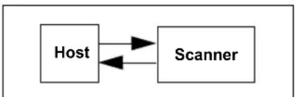
flowchart
graph LR
    A["Host"] <--> B["Scanner"]
Function: If a command with multiple fields is processed, some of the fields may have been processed properly while others were not. The changes will appear in the string echoed back so that the user will know which fields did or did not change.
Serial Cmd:
Default: Disabled
Options: 0 = Disabled 1 = Enabled
Serial Command Beep Status
Important: ESP will not function whenever this command is enabled.
Usage: Used to audibly verify the acceptance and validity of a command.
Definition: Causes the scanner to beep once whenever a K command is entered to indicate that the command was accepted and processed.
Function: If an invalid command is entered, the scanner beeps 5 times to indicate an invalid entry. However, this does not necessarily mean that all data fields have been entered incorrectly. Only one bad field needs to be found in order to activate the 5 beep response.
Serial Cmd:
Default: Disabled
Options: 0 = Disabled 1 = Enabled
Serial Verification
Control/Hex Output
Usage: Useful for viewing settings with binary characters when using serial command on a terminal.
Definition: Determines the response to a Serial Command Echo or status request command.
When set to Control, two characters are transmitted to represent a non-displayable character. For example, a carriage return will be shown as the two characters: ^M.
When set to Hex, the output is the hex character.
Serial Cmd:
Default: Control
Options: 0 = Control 1 = Hex
EZ Button
The EZ Button has four positions, selectable by the length of time the button is held down, and indicated by one, two, three, and four beeps in succession. Each position can be programmed for any of eight options.
Definition: Serves as a master switch to enable/disable the EZ Button status.
Serial Cmd:
Default: Enabled
Options: 0 = Disabled 1 = Enabled 2 = Trigger
3 = Unlatch Outputs 4 = Parameter Switch
Global Status
Disabled
When set to Disabled, the EZ Button does not function.
Enabled
When selected, the EZ Button is enabled and the function of each button position is selected by the EZ Button Mode command.
Trigger
When selected, the EZ Button acts as a trigger for the scanner to start and end read cycles. All other button operations are inactive.
In External Level: The read cycle endures for as long as the EZ Button is pressed, unless a timeout occurs and Timeout is enabled for End of Read Cycle.
In External Edge: As with Level, Edge allows a read cycle to be initiated by pressing the EZ Button, but unlike Level, the read cycle ends with a Good Read output, a timeout, or a new trigger.
Unlatch Outputs
In this configuration, the EZ Button will unlatch any logic outputs that have been latched.
Parameter Switch
The parameter switch toggles between custom defaults and power-on settings. The condition is the same as that achieved by sending the
EZ Button
Default on Power-On
Definition: When enabled, if the EZ Button is held down on power-on the scanner will default and save for power-on.
Serial Cmd:
Default: Enabled
Options: 0 = Disabled 1 = Enabled
Load Configuration Database
Definition: Allows the user to load the Configuration Database with calibration results. When the user performs a calibration using the EZ Button, all the database entries are moved down one index and the results of the calibration are saved to index 1. The results will be saved as current settings as well.
Serial Cmd:
Default: Enabled
Options: 0 = Disabled 1 = Enabled
Save for Power-On
Definition: If enabled, after calibration is complete, all parameters will be saved for power-on.
Serial Cmd:
Default: Disabled
Options: 0 = Disabled 1 = Enabled
EZ Button Modes
Usage: Useful for performing multiple, repetitive tasks at the work site.
Definition: Allows the user to program each of the EZ Button's 3 positions from a selection of 10 modes.
Serial Cmd:
Options:
| Single Beep Two Beeps Three Beeps | |
| 0 = Disabled 0 = Disabled 0 = Disabled | |
| 1 = Read Rate 1 = Read Rate 1 = Read Rate | |
| 2 = Calibration 2 = Calibration 2 = Calibration | |
| 3 = Save for Power-On 3 = Save for Power-On 3 = Save for Power-On | |
| 5 = Load New Master 5 = Load New Master 5 = Load New Master | |
| 9 = Bar Code Configuration 9 = Bar Code Configuration 9 = Bar Code Configuration | |
Disabled
When set to disabled, the associated button position will have no function associated with it, and the position will be skipped over.
Read Rate
Read Rate will be initiated when the associated button position is selected. Read Rate will perform decodes/second and is the same as sending a
Calibration
Calibration will be initiated when the associated button position is selected. To abort calibration, quickly press and release the EZ Button.
Save for Power-On
All scanner settings will be saved to non-volatile memory to be recalled on power-on whenever the associated button position is selected. This is the same as sending a
Load New Master
Functions in the same way as new master pin input whenever the associated button position is selected. The new master pin's Consecutive Decode requirement holds true for this function.
Bar Code Configuration
Enables Bar Code Configuration mode whenever the associated button position is selected. When enabled, the scanner can accept configuration commands from symbols. To disable, quickly press and release the EZ Button.
EZ Button Modes
EZ Button Operation
Single Beep (Position #1)
Hold down button until a single beep is heard.
Two Beeps (Position #2)
Hold down button until two quick beeps are heard.
Three Beeps (Position #3)
Hold down button until three quick beeps are heard.
Input 1
Definition: A programmable, discrete input used to reset counters, outputs or control optoelectrical settings.
Usage: For example, an application is setup so that a mismatch stops the production line by using outputs in a latch mode. A push-button switch can be connected to the input pin so that when pressed, it unlatches the output, allowing the line to resume operations.
Input Mode
Definition: Determines the functionality of the input.
Serial Cmd:
Default: Disabled
Options: 0 = Disabled
1 = Reset Counts
2 = Unlatch Output
Disabled
Definition: When set to Disabled, there is no effect on operation.
Reset Counts
Usage: Primarily used in test mode. Can also be used to reset counters daily.
Definition: When set to Reset Counts, a transition to the active state of the input will cause the scanner to reset the internal counters (See Counters on page 12-6).
Unlatch Output
Definition: This setting is used in combination with any of the three discrete outputs that are in Unlatch Mode 1. A transition to the active state will clear any of the three outputs that were previously latched.
Active State
Definition: Determines the function of the input pin.
Serial Cmd:
Default: Active Closed
Options: 0 = Active Open 1 = Active Closed
Note: If set to Match or Mismatch, Symbol Data Output Status will not take effect unless Matchcode Type is enabled and a master symbol is loaded into memory.
Configurable Output 1
Output On
| Usage: | This option provides discrete signalling to host software to control external devices such as PLCs and relays. It is useful for routing, sorting, and to prevent mis-packaging and mis-routing. |
| Definition: | Sets the discrete output functions for specific user-selected conditions. Allows the user to set the conditions under which an output (or outputs) will be activated. |
Serial Cmd:
Default: Mismatch or No Read
| Options: 0 = Mismatch or No Read |
| 1 = Match or Good Read |
| 2 = Mismatch |
| 3 = No Read |
| 4 = Trend Analysis |
| 5 = [reserved] |
| 6 = Diagnostic Warning |
| 7 = In Read Cycle |
Note: If Output On is set to Mismatch/No Read or Match/Good Read, a transition (switching) will not occur unless Matchcode Type is enabled and a master symbol is loaded into memory.
Mismatch or No Read
Activates a discrete output when the data does not match that of the master symbol or the symbol has not been decoded before the end of the read cycle.
Match or Good Read
Activates a discrete output when the symbol data matches the master symbol.
Note: If you want to output for a Good Read and Matchcode is not enabled, you can enable any output for Match.
Mismatch
Activates a discrete output whenever the symbol data does not match that of the master symbol.
No Read
Activates a discrete output whenever the symbol data is not decoded before the end of the read cycle.
Trend Analysis
Activates discrete output when a trend analysis condition is met, depending on the trend analysis option enabled.
Typically used when successful decodes are occurring but a discrete output is needed to flag a trend in quality issues.
Diagnostic Warning
Activates discrete output when a diagnostic warning condition is met, depending on the diagnostic option enabled.
Typically used when a discrete indication of a diagnostic condition is needed.
In Read Cycle
Activates a discrete output when the scanner is in a read cycle.
Configurable Output 1
Output State
Definition: Sets the active electrical state of the discrete output.
Serial Cmd:
Default: Negative
Options: 0 = Negative 1 = Positive
Pulse Width
Definition: Sets the time in 10 ms increments that the discrete output remains active.
Serial Cmd:
Default: 50
Options: 1 to 65535 (Divide the number entered on the command line by 100 for time in seconds)
Output Mode
Definition: Sets the condition in which the discrete output is de-activated.
Serial Cmd:
Default: Pulse
Options: 0 = Pulse
1 = Latch Mode 1
2 = Latch Mode 2
3 = Latch Mode 3
Pulse
This is the default mode of operation in which the programmable output is activated when the Output On condition has been met and held active for the duration of the selected pulse width.
Latch Mode 1 (Unlatch on Input 1 Pin)
In this mode the programmable output will be activated when the Output On condition is met. It will stay active until the state of the Input 1 pin changes from inactive to active or the proper mode is configured using the EZ Button.
Important: To unlatch using the Input 1 pin, the input status must be set to "Unlatch Outputs". To unlatch using the EZ Button, the button status must be set to Unlatch Mode.
Latch Mode 2 (Unlatch Opposite Condition)
The programmable output is activated when the Output On condition has been met and held active until the opposite condition selected under Output On has been met.
For example, if No Read is enabled under Output On, the programmable output will go active on a No Read and remain active until the opposite condition, a Good Read, occurs.
Latch Mode 3 (Unlatch Re-Enter Read Cycle)
The programmable output is active when the Output On condition has been met and is held active until a new read cycle begins.
Note: All of the Output On modes are inhibited when any Output on Warning is active for Output 1.
Trend Analysis Output 1
Note: Output On in Output 1 Parameters must be set to Trend Analysis for this output to function.
Usage: Useful in cases where the user doesn't want to shut down for one condition but wants to monitor quality and read conditions.
Definition: Applies Trend Analysis settings to Output 1.
With Trend Analysis, the user can track the occurrences and frequency of mismatches, No Reads, and the number of reads per trigger, and output the results to any of three outputs.
Example: Trend Analysis Mode = No Read
Number of Triggers = 25 triggers (read cycles)
Number to Output On = 4
Decodes per Trigger = 1
In this example, the scanner will activate an output when 4 No Reads occur within a period of 25 triggers (read cycles), at 1 decode per trigger.
Trend Analysis Mode
Definition: Sets the trend condition (Mismatch, No Read, Decodes/Trigger, Bad Symbol, or No Symbol) that will activate the output.
Serial Cmd:
Default: No Read
Options: 0 = Mismatch
1 = No Read
2 = Decodes/Trigger Threshold
3 = Bad Symbol
4 = No Symbol
Mismatch
Output will be activated when the number of mismatches equals the value entered for Number to Output On within the trigger window selected in Number of Triggers.
No Read
Output will be activated when the number of No Reads equals the value entered for Number to Output On within the trigger window selected in Number of Triggers.
Decodes/Trigger Threshold
Output will be activated when the number of decodes equals the value entered for Number to Output On within the trigger window selected in Number of Triggers.
Bad Symbol
Output will be activated when the number of Bad Symbol occurrences equals the value entered for Number to Output On within the trigger window selected in Number of Triggers.
No Symbol
Output will be activated when the number of No Symbol occurrences equals the value entered for Number to Output On within the trigger window selected in Number of Triggers.
Configurable Output 1
Number of Triggers
Definition: The number of triggers to examine for the trend analysis condition.
Serial Cmd:
Default: 0
Options: 0 to 255
Number to Output On
Usage: Example: If Number to Output On is set to 3 and Trend Analysis Mode is set to No Read, then the output will not be activated until 3 No Reads have occurred.
Definition: Sets the number of Trend Analysis Mode events (mismatches, No Reads, or reads/trigger as configured by Trend Analysis Mode) to occur within the trigger evaluation period before activating the associated output.
Serial Cmd:
Default: 0
Options: 0 to 255
Decodes/Trigger Threshold
Definition: When set to this mode, and when the appropriate output is set to output on trend analysis, the scanner will function in a Decodes per Trigger mode during the read cycle and the trend analysis operation. Output will be activated based on whether or not the symbol decode count at the end of the read cycle crosses the decodes per trigger threshold.
Note: Although this setup causes the scanner to function in a Decodes per Trigger mode, the decode count will only be appended to the symbol data if the status of the Decodes per Trigger command is enabled.
Serial Cmd:
Default: 0
Options: 0 to 65535
Diagnostics Output 1
Note: Output On in Output 1 Parameters must be set to Diagnostic Warning for this output to function.
Over Temperature
Serial Cmd:
Default: 0
Options: 0 = Disabled 1 = Enabled
Service Threshold
Serial Cmd:
Default: 0
Options: 0 = Disabled 1 = Enabled
Laser Current High
Serial Cmd:
Default: 0
Options: 0 = Disabled 1 = Enabled
Laser Current Low
Serial Cmd:
Default: 0
Options: 0 = Disabled 1 = Enabled
Low Temperature
Serial Cmd:
Default: 0
Options: 0 = Disabled 1 = Enabled
Configurable Output 2
Configurable Output 2
Note: Output 2 has the same parameters and default settings as Output 1.
Serial Cmd:
Trend Analysis Output 2
Note: Output On under Output 2 Parameters must be set to Trend Analysis for this output to function.
Serial Cmd:
Diagnostics Output 2
Note: Output On under Output 2 Parameters must be set to Diagnostic Warning for this output to function.
Serial Cmd:
Configurable Output 3
Note: Output 3 has the same parameters and default settings as Output 1 and Output 2.
Serial Cmd:
Trend Analysis Output 3
Note: Output On under Output 3 Parameters must be set to Trend Analysis for this output to function.
Serial Cmd:
Diagnostics Output 3
Note: Output On under Output 3 Parameters must be set to Diagnostic Warning for this output to function.
Serial Cmd:
Database Identifier Output
Usage: Useful in keeping track of which database entries read which symbols.
Serial Cmd:
Default: 0
Options: 0 = Disabled 1 = Enabled
Output Status
Disabled
When this command is disabled, no database identifier information will be output.
Enabled
When this command is enabled, the scanner will append a two-digit number and the characters "DB" to the data output following the separator for each symbol decoded using Configuration Database. For example, if the separator is an underscore character and the second database entry reads a symbol encoded with "data capture" during the read cycle, the symbol data output will be "data capture_DB02". If the database is not active, no identifiers will be attached to output.
Separator
Usage: The separator character separates the symbol data from the database identifier.
Serial Cmd:
Default:
Options: Any ASCII character
Quality Output
Definition: Allows the host to track the number of good reads per trigger by appending a five digit numeric field to the end of symbol data.
When enabled, symbol data is followed by a separator, followed by the five digits in the form of 00000. For example, a certain symbol that has been averaging 00100 decodes per read cycle suddenly drops to 00012, this would be a good indication that a problem has arisen even though good reads are still occurring.
Usage: Host system can monitor scanning performance (printing process, scanning environment changes, etc.) by setting thresholds in their processing or displaying the outputs for visual verification.
Quality Output Separator
Serial Cmd:
Default: , (comma)
Options: Any ASCII character
Note: For all serial configuration commands, the following characters cannot be used: NUL, <, >, and , .
Decodes/Trigger Status
Serial Cmd:
Default: Disabled
Options: 0 = Disabled 1 = Enabled
Direction Output
Serial Cmd:
Default: Disabled
Options: 0 = Disabled 1 = Enabled
Quality Output
Matchcode
Contents
Matchcode by ESP 7-2
Matchcode Serial Commands 7-2
Overview of Matchcode 7-3
Using Master Symbols....7-4
Matchcode Type 7-5
Sequence Step 7-10
New Master Pin....7-11
Match Replace....7-12
Mismatch Replace....7-13
This section explains the Matchcode output functions and setup.
Note: The characters NUL, <, >, and , can only be entered through embedded menus, not through ESP or serial commands.
Matchcode by ESP
Matchcode by ESP
Click this button to bring up the Matchcode menu.
To change a setting, double-click the setting and use your cursor to scroll through the options.

text_image
Parameters ESP Values Matchcode Matchcode Type Disabled Sequential Matching Increment Match Start Position 0 Match Length 1 Wild Card * Sequence on Noread Enabled Sequence Step 1 Sequence on Mismatch Disabled New Master Pin Disabled* + Match Replace Disabled* + Mismatch Replace EnabledTo open nested options, single-click the +.
Matchcode Serial Commands
Command Title Command Format
| Matchcode Type | |
| Master Symbol Database Size | |
| New Master Pin | |
| Configuration Database | |
| Sequence Step | |
| Enter/Delete Master Symbol Data | |
| Request Master Symbol Data | [for all] or |
| Match Replacement Message | |
| Mismatch Replacement Message |
Overview of Matchcode
Usage:
Matchcode is used in applications to sort, route, or verify data based on matching the specific symbol in a variety of ways, as defined in this section. For example, a manufacturer might sort a product based on dates that are embedded in the symbol.
Definition:
With Matchcode you can store master symbol data in the scanner's memory, compare this data against the scanned symbols, and define how symbol data and/or discrete signal output will be directed. A master symbol database can be set up for up to 10 master symbols.
Using Master Symbols
- Set Triggering Mode to External or Serial (see Trigger on page 4-5).
- Set Matchcode Type to an option that fits your application (see Matchcode Type on page 7-5).
- Define the output you want with your matchcode setup:
a) Data output (Symbol Data Output on page 6-4).
b) Discrete output (see Configurable Output 1 on page 6-20). - Select the number of master symbols you want to create. If more than one, send a
- Enter master symbol data in one of the following ways:
a) Use ESP to type in master symbol data directly into the Utilities menu.
b) Send a serial command with symbol data in the form of(or <) data> for single master symbol only).
c) Send acommand to scan the next symbol as the master symbol.
d) Enable the New Master Pin command and activate a discrete input to store the next symbol scanned as the master symbol (see New Master Pin on page 7-11).
Matchcode Type
Note: When Matchcode is set to Enabled, Wild Card or Sequential, Number of Symbols will default back to 1 (if set to any number greater than 1).
Definition: Allows the user to choose the way that master symbols will be compared with subsequently scanned symbols.
Note: First set Triggering Mode to External or Serial.
Serial Cmd:
Default: Disabled
Options: 0 = Disabled
1 = Enabled
2 = Sequential
3 = Wild Card
Disabled: Has no effect on operations.
Enabled: Instructs the scanner to compare symbols or portions of symbols with the master symbol.
Sequential Matching: Instructs the scanner to sequence after each match (numeric only) and compare symbols or portions of symbols for sequential numbers.
Note: If Matchcode Type is set to Sequential, Number of Symbols will default back to 1 (if set to any number greater than 1).
Wild Card: Allows the user to enter user defined wild card characters in the master symbol.
Sequential Matching
Usage: Used in tracking product serial numbers that increment or decrement sequentially.
Definition: With Sequential enabled under Matchcode Type, Sequential Matching determines if a count is in ascending (incremental) or descending (decremental) order.
Serial Cmd:
Default: Increment
Options: 0 = Increment 1 = Decrement
Matchcode Type
Match Start Position
Usage: Match Start Position is useful in defining specific portions of a symbol for comparisons. For example, if a symbol contains a part number, manufacturing date, and lot code info but the user is only interested in the part number information, Match Start Position can be set to only sort on the part number and ignore the rest of the characters.
Definition: Match Start Position determines the portions of symbols that will be matched by defining the first character in the symbol (from left to right) that will be compared with those of the master symbol, when Matchcode Type is set to Enabled or Sequential.
Function: For example, if Match Start Position is set to 3, the first 2 characters read in the symbol will be ignored and only the 3rd and subsequent characters to the right will be compared, up to the number of characters specified by Match Length.
Serial Cmd:
Default: 0
Options: 0 to maximum length allowed for master symbol
Note: Match Start Position must be set to 1 or greater to enable this feature. A 0 setting will disable this feature.
Match Length
Definition: Defines the length of the character string that will be compared with that of the master symbol when Match Start Position is set to 1 or greater. When Match Start Position is set to 0, no comparison will occur.
Usage: For example, if Match Length is set to 6 in a 10 character symbol, and Match Start Position is set for 2, only the 2nd through 7th characters (from left to right) will be compared.
Serial Cmd:
Default: 1
Options: 1 to 2710
Wild Card Character
Usage: For example, with Wild Card Character defined as the default asterisk, defining CR*34 as the master symbol will result in matches for CR134, CR234, but not CR2345. Entering the wild card at the end of the master symbol as in CR*** will result in matches for variable symbol lengths such as CR1, CR23, CR358, etc. provided that the number of wild card characters matches or exceeds the number of characters present.
Definition: Wild Card Character allows a user to define a wild card character as part of the master symbol.
Serial Cmd:
Default: * (asterisk)
Options: Any valid ASCII character
Matchcode Type
Sequence On No Read
Usage: Sequence On No Read is useful when the scanner needs to stay in sequence even if no decode occurs.
Definition: When Sequence On No Read is Enabled and Matchcode is set to Sequential, the scanner sequences the master symbol on every match or No Read. When disabled, it does not sequence on a No Read.
Serial Cmd:
Default: Enabled
Options: 0 = Disabled 1 = Enabled
As an example of Sequence on No Read Enabled, consider the following series of decodes:
| Master symbol Decoded symbol Master symbol after decode | ||
| 001 001 002 | ||
| 002 002 003 | ||
| 003 No Read 004 (sequenced on No Read) | ||
| 004 004 005 | ||
| 005 No Read 006 (sequenced on No Read) | ||
| 006 No Read 007 (sequenced on No Read) | ||
| 007 007 008 | ||
As an example of Sequence on No Read Disabled, consider the following series of decodes:
| Master symbol Decoded symbol Master symbol after decode | ||
| 001 001 002 | ||
| 002 002 003 | ||
| 003 No Read | 003 (not sequenced) | |
| 003 003 004 | ||
| 004 No Read | 004 (not sequenced) | |
| 004 No Read | 004 (not sequenced) | |
| 004 004 005 | ||
Sequence On Mismatch
Note: Matchcode must be set to Sequential for this command to function.
Usage: Enable this parameter if every trigger event should have a decode and more than one consecutive mismatch may occur. Disable this parameter if every trigger event should have a decode but no more than one consecutive mismatch may occur.
Definition: When set to Enabled, the master symbol sequences on every decode, match or mismatch.
When set to Disabled, the master symbol will not sequence whenever consecutive mismatches occur.
Serial Cmd:
Default: Disabled
Options: 0 = Disabled 1 = Enabled
The scanner will sequence the master to one more/less than the decoded symbol. As an example of Sequence On Mismatch Enabled, consider the following decodes:
| Master symbol | Decoded symbol Master | symbol after decode |
| 001 001 002 | ||
| 002 002 003 | ||
| 003 abc 004 | (sequenced on mismatch) | |
| 004 004 005 | ||
| 005 def | 006 (sequenced | on mismatch) |
| 006 ghi | 007 (sequenced | on mismatch) |
| 007 007 008 |
As an example of Sequence On Mismatch Disabled, consider the following decodes:
| Master symbol | Decoded symbol | Master symbol after decode |
| 001 | 001 | 002 |
| 002 | 002 | 003 |
| 003 | abc | 004 (sequenced because of previous match) |
| 004 | 004 | 005 |
| 005 | def 005 (sequenced because of previous match) | |
| 005 ghi 005 | (not sequenced because of previous mismatch) | |
| 005 | 005 | 006 |
You can access Master Symbol operations from the Utilities menu.
Sequence Step
Sequence Step
Usage: Useful in applications in which it is desirable to count by intervals other than 1.
Definition: Sequencing in Matchcode operations can occur in steps from 1 to 32,768.
Sequencing performs like a mechanical counter by displaying positive integers and a specific number of digits after rollovers.
For example, 000 - 3 = 997 (not -3) and 999 + 3 = 002 (not 1002).
Serial Cmd:
Default: 1
Options: 1 to 32768
Note: See
As an example of Sequence Step, if Sequence Step is set to 3 and Sequential Matching is set to Increment.
| Master Symbol Decoded | Symbol Master Symbol After Decode | |
| 003 001 003 | ||
| 003 002 003 | ||
| 003 003 006 | ||
| 006 004 006 | ||
| 006 005 006 | ||
| 006 006 009 | ||
New Master Pin
Usage: Some applications require the line worker to change the master symbol. This can be done by installing a switch at the location of the scanner. It is very common to have a keyed switch so that accidental switching does not occur.
Definition: After New Master Pin is enabled, a pulse can be received on the new master pin which will cause the scanner to record the next decoded symbol(s) as the new master symbol(s).
It is important to note that the enabling New Master Pin does not in itself cause a master symbol to be recorded. The master pin must then be activated momentarily (for a minimum of 10 ms) before a master symbol can be scanned into memory.
Serial Cmd:
Default: Disabled
Options: 0 = Disabled 1 = Enabled
After New Master Pin has been enabled and the pin activated, decodes will be saved in the master database beginning with master symbol #1. If the scanner is configured for a multisymbol read cycle (Number of Symbols is greater than 1), the remaining decodes will be saved in each consecutive master symbol location. For example, if Number of Symbols is set to 3 and New Master Pin is then activated, at the end of the next read cycle, the decoded symbols will be saved as master symbols 1, 2, and 3.
Match Replace
Usage: Provides a convenient shortcut for applications that need to output a predefined text string whenever a symbol matches a master symbol.
Definition: Outputs a user-defined data string whenever a match occurs and Matchcode is enabled.
Serial Cmd:
Default: Disabled
Options: 0 = Disabled 1 = Enabled
Replacement String
Definition: User-defined data string that, when enabled, replaces symbol data whenever a match occurs.
Serial Cmd:
Default: MATCH
Options: 1 to 128 ASCII characters
Mismatch Replace
Usage: Provides a convenient shortcut for applications that need to output a predefined text string whenever a symbol does not match a master symbol.
Definition: Outputs a user-defined data string whenever a mismatch occurs and Matchcode is enabled.
Serial Cmd:
Default: Disabled
Options: 0 = Disabled 1 = Enabled
Replacement String
Definition: User-defined data string that, when enabled, replaces symbol data whenever a mismatch occurs.
Serial Cmd:
Default: MISMATCH
Options: 1 to 128 ASCII characters
Mismatch Replace
8 Diagnostics
Contents
Diagnostics by ESP....8-2
Diagnostics Serial Commands....8-2
Counts....8-3
Hours Since Last Reset 8-4
Warning Messages 8-5
Laser Current Warning....8-7
Present Operating Temperature (Deg. C) 8-8
High Temperature Threshold 8-9
Low Temperature Threshold....8-10
Lifetime Hours....8-11
Service Message....8-12
This section describes warning and operating messages and their settings.
Important: Since Warning Messages and NOVRAM Messages are not enabled by default, these messages will not be displayed. However, if you suspect that erroneous defaults are occurring, enable Warning Messages and NOVRAM Messages by sending
Note: The characters NUL, <, >, and , can only be entered through embedded menus, not through ESP or serial commands.
Diagnostics by ESP
Click this button to bring up the Diagnostics menu.
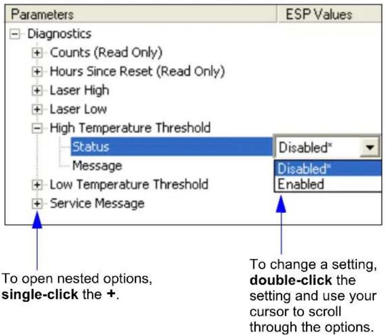
text_image
Parameters Diagnostics + Counts (Read Only) + Hours Since Reset (Read Only) + Laser High + Laser Low - High Temperature Threshold Status Message + Low Temperature Threshold + Service Message ESP Values Disabled* Disabled* Enabled To open nested options, single-click the +. To change a setting, double-click the setting and use your cursor to scroll through the options.Diagnostics Serial Commands
| Command Title Command Format | |
| Warning Message Status | |
| Lifetime Hours | |
| High Temperature Warning | |
| Low Temperature Warning | |
| Power-On/Resets Counts | returns: (Read-Only) |
| Hours Since Last Reset | returns: (Read-Only) |
| Present Operating Temperature | returns: (Read-Only) |
| Service Message | |
| Laser Current Warning |
Counts
(This command is Read-Only.)
Power-Ons
Definition Returns the number of times the scanner has been re-powered or a watchdog reset occurs.
Serial Cmd: Send:
Returns:
Read-Only Range: 0 to 65535 power-ons.
Resets
Usage: Used for detecting unwanted resets caused by power supply problems or ESD transients.
Definition Resets include watchdog reset, and
Serial Cmd: Send:
Returns:
Read-Only Range: 0 to 65535 resets.
Parameter Saves
Definition Returns the number of times parameters are written to memory, including
Serial Cmd: Send:
Returns:
Read-Only Range: 0 to 65535 saves.
Hours Since Last Reset
Hours Since Last Reset
(This command is Read-Only.)
Usage: Used as a troubleshooting tool that can help pinpoint the cause of a reset.
Definition: Records the number of hours and minutes of operation since the last system reset.
Serial Cmd: Send:
Returns:
Read-Only 0 to 255 hours, 0 to 59 minutes.
Warning Messages
Important Note: Warning Message Status must be enabled before any warnings in this menu can be displayed.
| Usage: | These messages serve as a flag to service a scanner or as an early warning that potential problems could arise. They are particularly useful in factories that run constantly and can’t afford down time. |
| Definition: | Warning messages that relate to the environment and condition of the scanner can be defined and set to activate specific outputs.Note: When enabled, the error condition will override all other operational modes configured for the output.When enabled, laser current and NOVRAM warning messages will be transmitted to the host or any active port whenever the pre-defined conditions are met. |
| Function: | When enabled, warning messages will be transmitted to the host or any active port.Note: This option must be enabled before any other warning messages can be transmitted. |
Warning Message Status
Serial Cmd:
Default: Disabled
Options: 0 = Disabled
1 = Enabled
Laser High Status
When enabled, a message is transmitted whenever the laser current exceeds a factory-calibrated reference value which cannot be altered. The message repeats once every 30 minutes until the condition is corrected.
Usage: Alerts the user to impending laser failure.
Definition: Enables the Laser High message.
Serial Cmd:
Default: Enabled
Options: 0 = Disabled 1 = Enabled
Warning Messages
Laser Low Status
When enabled, a message is transmitted whenever the laser current falls below a factory-calibrated reference value which cannot be altered. The message repeats once every 30 minutes until the condition is corrected.
Usage: Alerts the user to impending laser failure.
Definition: Enables the Laser Low message.
Serial Cmd:
Default: Enabled
Options: 0 = Disabled 1 = Enabled
NOVRAM/Reset Warning Status
When enabled, a 7-character message is sent whenever the system detects a warning condition.
Important: Warning Message Status must be enabled before the NOVRAM message in this menu can be transmitted.
Usage: Alerts the user to NOVRAM failure.
Serial Cmd:
Default: Enabled
Options: 0 = Disabled
$$ 1 = \text { Enabled } $$
Note: If you suspect that erroneous defaults are occurring, enable NOVRAM Messages by sending
Warning messages for NOVRAM can appear in one of four formats:
Indicates that diagnostic lifetime hours, power-on counts, and reset counts have been lost. The message repeats once every 30 minutes.
Indicates a problem with laser current factory reference. The message repeats once every 30 minutes.
Indicates that NOVRAM settings have been defaulted either by a user-initiated default or by a problem with the scanner. This message is sent ONLY ONCE.
Indicates that the factory NOVRAM settings have been defaulted. This message is sent ONLY ONCE upon reset.
Laser Current Warning
Alerts the user to impending laser failure.
High Current Status
Definition: The High Current message is output whenever the laser current exceeds the factory-defined maximum. The message repeats once every 30 minutes until the condition is eliminated.
Serial Cmd:
Default: Disabled
Options: 0 = Disabled
1 = Enabled
High Current Message
Definition: This message is output whenever the laser current exceeds the factory-defined maximum.
Serial Cmd:
Default: HIGH_LASER
Options: Any ASCII string up to 10 characters.
Low Current Status
Definition: The Low Current message is output whenever the laser current exceeds the factory-defined minimum. The message repeats once every 30 minutes until the condition is eliminated.
Serial Cmd:
Default: Disabled
Options: 0 = Disabled
1 = Enabled
Low Current Message
Definition: This message is output whenever the laser current exceeds the factory-defined minimum.
Serial Cmd:
Default: LOW_LASER
Options: Any ASCII string up to 10 characters.
Present Operating Temperature (Deg. C)
Present Operating Temperature (Deg. C)
(This command is Read-Only.)
Usage: Used for setting Over Temperature Threshold and Under Temperature Threshold.
Definition: Indicates temperature of the environment immediately outside of the scanner. A thermal sensor on the main PCB measures the internal temperature of the scanner. From this, a case-differential constant is subtracted to yield an estimated external temperature.
Serial Cmd: Send:
Returns:
Note: When viewing the Present Operating Temperature, allow at least 20 minutes after startup for the scanner's inside and outside temperatures to stabilize.
High Temperature Threshold
A message can be defined that will display when a user-set High Temperature Threshold has been reached. The message repeats once every 30 minutes until the condition is corrected. This value is a reference to the external ambient temperature in the environment around the scanner.
High Temperature Degrees
Usage: Helps ensure that the scanner is being used within its temperature specification. Also, since hotter environments tend to shorten the life of electronics components, a user may want to set the temperature threshold closer to the nominal temperature of 25^ .
Definition: A user can set a temperature value that when exceeded will cause a high temperature message to be displayed. If High Temperature Threshold is set to zero, then the warning message will be disabled.
Serial Cmd:
Default: Disabled
Options: 0 = Disabled
1 = Enabled
High Temperature Message
Definition: The user can enter a message of up to 10-characters that will be displayed whenever High Temperature Threshold is exceeded.
Serial Cmd:
Default: HIGH_TEMP
Options: Any 1 to 10 character ASCII string except NUL, <, or >.
Low Temperature Threshold
Low Temperature Degrees
Usage: Helps ensure that the scanner is being used within its temperature specification.
Definition: The user can set a low temperature value that, whenever the ambient temperature falls below it, causes a low temperature message to be displayed. If Low Temperature Threshold is set to zero, the warning message will be disabled.
Serial Cmd:
Default: Disabled
Options: 0 = Disabled
1 = Enabled
Low Temperature Message
Definition: The user can enter a message of up to 10-characters that will be displayed whenever the ambient temperature falls below the Low Temperature Threshold.
Serial Cmd:
Default: LOW_TEMP
Options: Any 1 to 10 character ASCII string except NUL, <, or >.
Lifetime Hours
A message can be defined that will be transmitted whenever the scanner's elapsed time clock exceeds the set hours threshold. The message repeats one time every 30 minutes.
Hours Threshold
Usage: Used for setting up a preventive maintenance program.
Definition: A user can set a time in hours that will cause a message to be sent whenever the scanner's run time exceeds this value.
The elapsed time is the time the scanner is powered up.
Serial Cmd:
Default: 2500 (x 10 = 25,000 hours)
Options: 0 to 65534
Note: Hours entered are 1/10 of the actual hours.
Message
Definition: The user can enter a message of up to 10-characters that will be displayed whenever the hours threshold is reached or exceeded.
Serial Cmd:
Default: SERVICE
Options: Any 1 to 10 character ASCII string except NUL, <, or >.
Service Message
Service Message
When Service Message is enabled, a message of up to 10 ASCII characters is sent whenever the system detects that the service timer's limit has been reached. The service timer is reset at power-on, meaning that the service timer's limit is the amount of time since last reset. Service timer increments can be set in seconds or minutes.
Serial Cmd:
Default: 0
Options: 0 = Disabled 1 = Enabled
Service Message
Serial Cmd:
Default: SERVICE
Options: An ASCII string between 1 and 10 characters.
Threshold
Serial Cmd:
Default: 300 (5 minutes)
Options: 1 to 65535
Resolution
Serial Cmd:
Default: Seconds
Options: 0 = Seconds 1 = Minutes
[9] Calibration
Contents
Calibration Serial Commands 9-2
Calibration Steps....9-3
Calibration Routine 9-4
Calibration Results....9-5
Configuration Database 9-6
Optoelectric Control 9-8
Advanced Calibration Features....9-14
Calibration by Embedded Menu....9-17
The purpose of calibration is to optimize the scanner's optical settings (focus, gain, and tracking) and scan speed to obtain the highest read rates in one or several symbol positions as required by the user's application. This section includes the overall steps in calibration and specific steps for calibration by ESP, serial command, and embedded menus. For most applications calibration is the only optical setup required.
Changes to motor speed, focus, speed, gain, tracking, and AGC can also be made individually by manual command.
Calibration Methods
There are three ways to initiate calibration:
- ESP Calibration menu
- Serial command <@CAL>
- Embedded menu <@>
Note: Calibration does not function with PDF417 symbols. However, you can substitute a Code 128 symbol with the same mil size as your PDF417. When you do this, enable Code 128 and disable Raster scanning. After calibration, switch back to PDF417 and Raster scanning.
Calibration Serial Commands
Calibration Serial Commands
Command Title Command Format
| Optoelectric Control | |
| Configuration Database | |
| Save Configuration Database | |
| Load Configuration Database | |
| Request Configuration Database | orfor entire database. |
| Autocalibration |
Calibration Steps
Follow this procedure for all three methods of calibration:
- Position your symbol at the distance used in your application and confirm that it is at a distance within the specifications for that symbol size (see Position Scanner and Symbol on page 1-5).
- If you are not certain of the code type, enable all code types by sending a
command from the terminal window, or clicking on the Autodiscrimination button in Calibration/Advanced in ESP.
- Start the calibration procedure.
Note: Once a successful calibration is completed, you may want to save the setting to the calibration database (see Configuration Database on page 9-6).
-
Repeat calibration at other ranges and/or symbol types you might be scanning in your application.
-
Check your readings at each end of the scan width required for your application, keeping in mind that the scan width testing may not produce results that are entirely symmetrical.
Note: If you are setting up for laser framing, be sure that you only test for calibration in the active areas of the scan beam.
- To save the new settings (including focus, gain, and tracking) for power-on, use the Send/Recv button or send a
command.
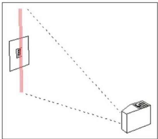
natural_image
Diagram showing two devices connected by a dashed line, with a vertical red line and a rectangular panel on the left (no text or symbols)See Configuration Database on page 9-6 to learn how to setup a database using calibration or manually specified values.
See Advanced Calibration Features on page 9-14 for ways to speed up and improve your calibration process.
Note: To silence the beeper, send
Calibration Routine
To calibrate gain, tracking, focus position, and scan speed automatically:
- Click the Calibration button near the top of the screen.
- Click the Calibrate button to start calibration.

A "Calibration in Progress..." message will be displayed on your monitor along with the pass number and information on the focus position, gain, tracking and read rate.
Allow some time for the scanner to cycle through the settings. Do not move or disturb the scanner or symbol while calibration is in progress. (It might take 2 to 3 minutes to complete.)
- When completed, the settings that provided the highest read rate will be selected. You will see one of the following messages: "Calibration Passed" or "Calibration Failed". If calibration passed, you will continue to see the read rate percentage and symbol data in the open pane below the data.
Calibration by Serial Command
To start the calibration process by serial command, send <@CAL> from ESP's Terminal.
Calibration Results
When a calibration command is sent, the scanner first steps through a coarse grid of focus settings, looking for readable symbols, and recording the highest read rates it encounters. This is Pass 1. During Pass 2, the scanner returns to the focus position where it found the best read rate and steps through a finer grid of focus, gain and tracking settings. The software evaluates the results and selects the best data. If calibration passes, a “Calibration Passed” message is displayed at the top of the window.
To load the settings obtained from calibration into the Configuration Database:
- Perform the calibration routine described in Calibration Routine on page 9-4.
- Click on the Configuration Database tab.
- Set Number of Active Database Settings and make your selection in Optoelectric Control in the menu tree to the left of the Database tab.
- Click on an index to load standard settings.
- Click Load Standard Settings to Database button.
This will put Focus, Gain, and Tracking settings that resulted from calibration into the database index. - Repeat this procedure for other indexes.
You can also enter individual values in any of the seven indexes by double-clicking anywhere on the index row and making changes in the popup text box.
Configuration Database
Configuration Database by Serial Command
Note: You can also set Focus, Gain Settings, Tracking Adjustment, Scan Speed, Laser Framing, and Background Color individually.
Definition:
The Configuration Database allows the user to save multiple scanner configuration settings. The database can be used to save the most commonly used configurations, making the scanner easily adaptable to changing applications, or it can be used in conjunction with Optoelectric Control, to change configurations dynamically.
When Optoelectric Control is set to Control Trigger (Optoelectric Control Mode), the first seven indexes can be switched by external inputs. Each database configuration setting is assigned to a control trigger sequence.
The table below illustrates the relationship between control trigger sequence and database indexes.
| I | Active Trigger(s) = 1, 2, 3 | Active Trigger(s) = 1, 2 A | Active Trigger(s) = 1 | ||||||
| Control Triggers Control | Triggers Control Triggers | ||||||||
| n | d | e | x | 3 | 2 | 1 | 3 | 2 | |
| 10 | 0 | 1 | 0 | 0 | 0 | 1 | / | 0 | |
| 20 | 1 | 0 | 1 | 1 | N | ||||
| 30 | 1 | 1 | 1 | 0 | Disabled | A | |||
| 41 | 0 | 0 | Disabled | 1 | A | ||||
| 5101 | N/A | N/A | N/A | ||||||
| 6110 | N/A | N/A | N/A | ||||||
| 7111 | N/A | N/A | N/A | ||||||
0 = Inactive Input State
1 = Active Input State
Serial Cmd:
Important: Control Trigger 3 uses the External Trigger input. When this input is active, there is no external trigger available to the scanner. Therefore, when Control Trigger 3 is active and External Trigger Mode is selected, a read cycle will be triggered by an active input from any of the control trigger inputs.
Since an active state on one of the control inputs is required to trigger a read cycle, sequence "000" would not be valid. When Control Trigger 3 is active, the sequence starts at "001". This allows a maximum of 7 accessible database settings. When Control Trigger 3 is not active, the sequence starts with all active inputs disabled.
Configuration Database by ESP
Click this button to bring up the Calibration view. Then select the Configuration Database tab to display the view shown below.
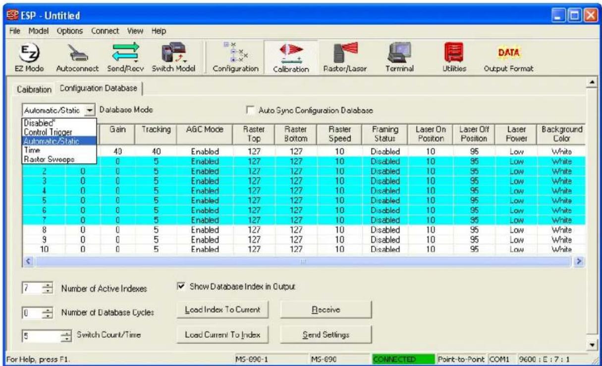
text_image
ESP - Untitled File Model Options Connect View Help EZ Mode Autoconnect Send/Recv Switch Model Configuration Calibration Raster/Laser Terminal Utilities DATA Calibration Configuration Database Automatic/Static Database Mode Auto Sync Configuration Database Disabled* Control Trigger Automatic/Static Time Raster Sweeps Gain Tracking AGC Mode Raster Top Raster Bottom Raster Speed Framing Status Laser On Position Laser Off Position Laser Flower Background Color 40 40 Enabled 127 127 10 Disabled 10 95 Low White 0 5 Enabled 127 127 10 Disabled 10 95 Low White 2 0 0 Enabled 127 127 10 Disabled 10 95 Low White 3 0 0 Enabled 127 127 10 Disabled 10 95 Low White 4 0 0 Enabled 127 127 10 Disabled 10 95 Low White 5 0 0 Enabled 127 127 10 Disabled 10 95 Low White 6 0 0 Enabled 127 127 10 Disabled 10 95 Low White 7 0 0 Enabled 127 127 10. Disabled 10.95 8 0 0 Enabled 127.127.10. Disabled 10.95 9 0 Enabled 127.127.10. Disabled 10.95 10 0 Enabled 127.127.10. Disabled 10.95 Number of Active Indexes ✓ Show Database Index in Output Number of Database Cycles Load Index To Current Receive Switch Count/Time Load Current To Index Send Settings For Help, press F1. MS-890-1 MS-890 CONNECTED Point-to-Point COM1 9600 : E : ? : ?All the database settings in the
Save Settings to Configuration Database
To save index values by serial command, use the following:
Load Settings from Configuration Database
To load index values by serial command, use the following:
Request Configuration Database Settings
To request index values, use the following:
Optoelectric Control
Note: Optoelectric Control requires the assembly of a Configuration Database.
Optoelectric Control Mode
Usage: Useful where different symbol types, sizes, qualities or distances require more that one optical setup (focus, gain, and tracking) for dynamic optical changes.
Definition: A database index of up to seven pre-defined optical indexes of settings defining focus, gain, and tracking can be accessed and applied in the following modes:
- A timer in which all settings cycle throughout the time duration.
- An automatic search for the best database index.
- A combination of up to three control trigger inputs to dynamically select the optimum database index.
The index settings can also be saved and recalled selectively, or reviewed with a Request Database Settings command.
Serial Cmd:
Default: Disabled
Options: 0 = Disabled
1 = Control Trigger
2 = Automatic/Static Mode
3 = Timer
4 = Number of Raster Sweeps
Disabled
Definition: When disabled, the scanner uses the standard configuration settings that are set in the Calibration tree and shown to the right of Standard in the Database Index.
Serial Cmd:
Control Trigger (Optoelectric Control Mode)
Usage:
Useful where different symbol types, sizes, and/or distances benefit from pre-defined optical setups (focus, gain, and tracking) that can be accessed 'on the fly' according to the combination of input states.
Definition:
When Optoelectric Control mode is set to Control Trigger, input 1, new master pin, and the trigger input pins are de-activated and re-assigned as control triggers. When activated, a read cycle will be triggered and—in accordance with their respective states—selected from a database of up to seven pre-defined optical settings of Focus, Gain, and Tracking. (See Configuration Database on page 9-6)
Serial Cmd:
Using Control Trigger
Set up your application's symbols by symbology type/size in the various positions and/or code type/size at which they will likely appear.
Set up your sensors or other controls. For example, the three object sensors, 1, 2 and 3, are connected to input 1, new master pin, and trigger input respectively. The bar-coded packages on the left are numbered here according to their database index numbers. Package #7 will cross all three of the sensors and thus activate the settings for index #7.
In this scenario only four index settings are possible. However, up to seven combinations are possible with other input devices such as PLCs.
You can also enable/disable any combination controls by clicking on the Control Trigger Status buttons on the bottom of the Control Trigger Map. The red buttons indicate active states on the three control triggers. The combination of active/inactive triggers determines the focus, gain, and tracking settings that will be applied during a read cycle. For example, if only Control Trigger 1 is active, the focus, gain, and tracking values that appear in the top row will be applied.
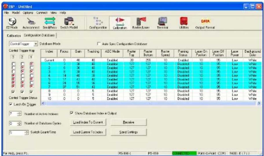
text_image
ESP - Untitled File Mode Options Connect View Help EZ Mode Autoconnect Send/Rece Switch Model Configuration Calibration Roster Laser Terminal Utilities DATA Calibration Deraquation Database Control Trigger Database Mode Auto Sync Configuration Database Control Trigger Map Index Focus Gain Tracking AISC Mode Faster Top Faster Bottom Faster Speed Framing Status Laser On Position Laser Off Position Laser Power Background Color 3 2 1 Current 0 46 40 Enabled 20 255 10 Enabled 10 95 Low White 1 2 38 40 Enabled 127 127 10 Disabled 10 95 Low White 2 6 36 40 Enabled 127 127 10 Disabled 10 95 Low White 3 8 38 40 Enabled 127 127 10 Disabled 10 95 Low White 4 14 48 38 Enabled 127 127 10 Disabled 10 95 Low White 5 17 43 48 Enabled 127 127 10 Disabled 10 95 Low White 6 24 55 36 Enabled 127 127 10 Disabled 10 95 Low White 7 27 51 43 Enabled 127 127 10 Disabled 10 95 Low White 8 0 0 5 Enabled 127 127 10 Disabled 10 95 Low White 9 0 0 5 Enabled 127 127 10 Disabled 10 95 Low White 10 0 0 5 Enabled 127 127 10 Disabled 10 95 Low White ✓ Larch On Trigger 7 Number of Active Indexes ✓ Show Database Index in Output 0 Number of Database Cycles Load Index To Current Receive 5 Switch Count/Time Load Current To Index Send Settings For Help, press F:\MS-806-L PS-859 CONNECTED: Point-to-Point COMI S600:E:7:1Optoelectric Control
Automatic/Static (Optoelectric Control Mode)
Usage: Useful in a static application in which the symbol is in front of the scanner when the read cycle begins.
Definition: Selects the optimum setting from the Configuration Database.
When selected, the scanner cycles once through all the Configuration Database settings from the closest to the furthermost focal position, testing first for optimal signal, then for a successful decode.
Note: Since focus positions are tested in ascending order, the closer the symbols are to the scanner, the quicker the best focus position will be found.
Important: The maximum time to move from the most inside focus position to the most outside focus position is 400 ms. One focus position change takes 10 ms.
Serial Cmd:
Timer Mode (Optoelectric Control Mode)
Usage: Useful in applications in which there is enough time to cycle through the database index.
Definition: When this mode is selected, the scanner cycles through database settings at a time interval determined in Timer Value setting. (See Timer/Switch Value on page 9-11.)
Important Note: The maximum time to move from the most inside focus position to the most outside focus position is 400 ms. One focus position change takes 10 ms.
Serial Cmd:
Note for Multisymbol: With Multisymbol enabled for more than one symbol, and either Timer or Automatic/Static mode enabled, the scanner may not locate symbols that are scanned at various ranges. The reason for this is that once a symbol is located from the optical database index, the scanner will continue to search for symbols that meet that index of focus, tracking and gain settings.
Number of Active Database Settings
Usage: Can be useful when certain settings that are needed for one application are not needed in another and processing time is at a premium.
Definition: This value sets the number of configuration database settings (in Database Index) that are active. If Control Trigger mode has been selected, this setting is ignored.
Serial Cmd:
Default: 1
Options: Any number from 1 to 7.
Latch on Trigger
Usage: Useful when only one database index is required for the application.
Definition: This feature is only used in Control Triggermode. If enabled, the configuration database settings selected at the start of a read cycle will remain active during the entire read cycle. If Latch on Trigger is disabled, depending on the control trigger inputs, the scanner's optical settings can change throughout the read cycle.
Note: When Control Trigger #3 is enabled, Latch on Trigger is also enabled regardless of its previous setting.
Serial Cmd:
Default: Enabled
Options: 0 = Disabled
1 = Enabled
Timer/Switch Value
Usage: Useful in slower applications where there is enough time to cycle through the database index.
Definition: When Timer mode is enabled, Timer Value is the time interval in which database index settings are cycled.
Serial Cmd:
Default: 5
Options: 0 to 255 (increments of 10ms)
Optoelectric Control
Control Trigger 1 Status
Definition: When Control Trigger mode is enabled, Control Trigger #1 takes over Input 1 (see Input Mode on page 6-19) and uses it to select an optoelectric configuration from the configuration database. Active state is set by Input 1 serial command.
Serial Cmd:
Default: Disabled
Options: 0 = Disabled 1 = Enabled
Control Trigger 2 Status
Definition: New Master Pin is used for Control Trigger #2. When enabled and Mode is set to Control Trigger, this input is used to select an optoelectric configuration from Configuration Database. Active State is "Active Closed".
Serial Cmd:
Default: Disabled
Options: 0 = Disabled 1 = Enabled
Control Trigger 3 Status
Definition: Trigger Input is used for Control Trigger #3. When enabled and Mode is set to Control Trigger, this input is used to select an optoelectric configuration from the Configuration Database. Active State is set by the External Trigger State serial command.
Serial Cmd:
Default: Disabled
Options: 0 = Disabled 1 = Enabled
Database Cycles
Definition: Database Cycles refers to the number of times the scanner will load the series of active entries when it is set to Timer or Raster Sweep modes. When set to 0, the scanner will cycle repeatedly through all active database entries until the read cycle ends. When set to a value greater than 0, the scanner will only load the active database entries for the defined number of times before staying with the last active entry for the remainder of the read cycle.
Serial Cmd:
Default: 0 Options: 0 to 255
Advanced Calibration Features
In the Advanced tab in the Calibration menu you can constrain the scan width of the scan beam with Laser Framing and set up the rules the scanner will follow during calibration procedure. See Laser Framing on page 10-7 for information on laser framing.
Auto Range
Usage: Enabling Auto Range improves focus acquisition speed where extraneous objects are not mistaken for symbols.
Definition: With Auto Range enabled, the scanner will focus outward and not begin the calibration routine until an object is detected by signal strength.
Serial Cmd:
Default: Enabled
Options: 0 = Disabled 1 = Enabled
Using Auto Range
- Be sure there are no extraneous objects between the symbol and the scanner.
- Click on the Advanced tab in the Calibration menu.
- If Auto Range is not enabled, click on it to enable it.
- Click the Calibrate button to start calibration.
- Examining the read rates in the Results graph following calibration.
Starting Focus Position
Usage: Starting Focus Position can improve focus acquisition speed during calibration when the approximate range of the symbol is known.
Definition: With Auto Range enabled, the scanner will begin the calibration routine at the focal range set in Starting Focus Position.
Serial Cmd:
Default: 0
Options: 0 to 40
After you've used calibration and observed the progress of the first and second passes in the graph and table in the Results tab, you should sense a relationship between focus position and the distance to the symbol.
Improving the speed and accuracy of focus position setup:
- Click on the Advanced tab in the Calibration menu.
- If Auto Range is enabled, click on it to disable.
- From previous results, estimate the value of Starting Focus Position and drop down one or two positions.
For example, if you estimate the distance to your symbol to correspond to a Starting Focus Position of 6, enter 5 or 4 to be certain of not missing the peak performance distance.
- Click the Calibrate button to start calibration.
- Examining the read rates in the Results graph following calibration.
Focus Step Size
Usage: Increasing the Focus Step Size can improve focus acquisition speed for symbols.
Definition: Focus Step Size is the number of focus increments that will be stepped through during the first calibration pass. The range is 2 to 5. The higher values will result in fewer readings during the first pass but will increase the risk of missing the peak performance position.
Serial Cmd:
Default: 5
Options: 2 to 5
Improving the speed and accuracy of focus step size setup:
- Click on the Advanced tab in the Calibration menu.
- If Auto Range is enabled, click on it to disable.
- Enter a value in Focus Step Size.
- Click the Calibrate button to start calibration.
- Examine the read rates in the Results graph following calibration.
Calibration by Embedded Menu
To calibrate via the embedded Calibration menu, do the following:
- Place the sample symbol at a fixed position in the center of the read range being tested.
- Enter Calibration menu by sending an <@> command from a terminal.
| MICROSCAN SYTEMS INC. | |||||
| AUTO CALIBRATION SETUP MENU | |||||
| To make changes, press appropriate key from list below: | |||||
| Motor Speed.....M = INCREMENT.....N = DECREMENT | |||||
| Gain Setting.....G = INCREMENT.....F = DECREMENT | |||||
| Tracking.....T = INCREMENT.....R = DECREMENT | |||||
| Focus Position.....P = INCREMENT.....0 = DECREMENT | |||||
| AGC Status.....S = ENABLE/DISABLE | |||||
| Laser Power.....L = HIGH/LOW | |||||
| PDF 417 Decode Test....D = ENABLE/DISABLE | |||||
| MENU OPTIONS: | MENU SELECTIONS | ||||
| START Auto Calibration.....A | MENU Calibration Results.....1 | ||||
| RECALL Initial Settings.....B | MENU Raster/Laser Framing Setup.....2 | ||||
| SAVE Settings to Data Base...C | MENU Configuration Data Base.....3 | ||||
| EXIT Calibration Setup.....ESC | MENU Advanced Setup.....4 | ||||
| Laser Power = LOW AGC = ENABLED PDF 417 Test = DISABLED | |||||
| Scan | | | | | AGC | Rate Motor Gain Track Focus Level _401 400 55 30 9 135 0 % | |||||
- If the application requires a change in scan rate, adjust the motor speed now with the M or N commands.
Note: All single letter commands must be entered in upper case. - Start calibration by typing an uppercase A from your terminal while in the calibration menu.
Note: A user can abort calibration at any time by pressing the ESC key on the terminal. No other keystroke has any effect while in calibration. - Wait for calibration to cycle through its settings.
A Calibration in Progress message will be displayed. A new text line will appear below the menu displaying the progress of the calibration. - As with the serial command, repeat the routine at other positions in your scan range and width and save each position to the configuration database.
- If not successful, a Calibration Failed message will be displayed. If successful, a Calibration Passed message will be displayed along with other settings.
Note: Focus positions Inside, Outside, and Set posted near the bottom of the above menu are explained more fully in Calibration Results in Embedded Menus on page 9-20.
Note: If you are using the 9-pin configuration port and doing calibration by serial command or embedded menus, you will be able to view decoded symbol data in the menu. However, after exiting the Calibration menu, you will not be able to see symbol data without sending the following command:
Scanner Settings by Embedded Menus
Motor Speed, Gain Setting, and Tracking adjustments affect the read performance.
Focus controls a stepper motor that physically slides a lens back and forth to control focal length. These settings are adjusted automatically in calibration.
The status of these parameters is displayed on the bottom line of the menu under Motor, Gain, Track, and Focus. These settings are incremented or decremented by pressing the indicated key shown on the menu. PDF417 Decode, AGC Status, Laser Power, and Raster Status use single commands to toggle between states.
AGC Status
Typing S toggles AGC between Enable/Disable, as displayed on a the status line near the bottom of the menu. With AGC disabled this value is simply the Gain setting. However, with AGC enabled, this value represents the gain the scanner has to set to maintain the desired signal amplitude. If a symbol is close to the scanner, the AGC level should be a small value because the scanner does not need much gain to achieve the desired signal amplitude. However, as a symbol gets farther away from the scanner, this value will increase to maintain the signal amplitude.
Laser Power
Typing L toggles between High and Low laser settings.
PDF417 Decode Test
Typing D toggles the PDF417 Decode Test between Enable/Disable, as displayed on a the status line near the bottom of the menu. Once set to Enabled, PDF417 only is enabled and a special test mode is enabled that displays the decodes per second of a full PDF417 symbol. While calibration is not performed in this mode, you can still adjust settings manually. This special read rate will remain enabled until the Calibration menu is exited or PDF417 is disabled with another D command.
Note: This mode averages decode and capture time over a series of readings, thus assuring for a smooth read rate output, but at the cost of delayed reaction to symbol movement and user setting changes.
Calibration Embedded Menu Options
START Calibration
Typing A initiates an calibration sequence. Once entered, no other keystrokes will be accepted with the exception of the ESC key, which terminates the routine.
RECALL Initial Settings
Typing B restores the original settings that were present upon entering the Calibration Setup Menu. These settings include Motor Speed, Gain, Tracking, and Focus.
SAVE Settings to Database
Typing C saves the current Gain, Tracking, and Focus settings to the Configuration Database. The database is made up of indexes 1 through 7. Current settings will be saved to the first open index.
EXIT Calibration Setup Menu
To exit the Calibration Setup menu, press the ESC key. The following prompt will be displayed: "Do you want to save calibration settings for power on? (Y=yes N=no)."
Typing Y will cause the current settings in the Calibration Setup menu to be saved to Flash Memory for recall when the scanner is powered up at a later date. These settings include Motor Speed, Gain, Tracking, Focus, AGC Status, Laser Power, and Raster Status. Typing N will cause the scanner to be reset without saving the settings to Flash memory.
Menu Selections
Typing 1 will take you to the Calibration Results menu.
Typing 2 will take you to the Raster/Laser Framing Setup menu.
Typing 3 will take you to the Configuration Database menu.
Typing 4 will take you to the Advanced Setup menu.
Calibration Results in Embedded Menus
To access Calibration Results menu from within the Calibration Setup menu, type the numeral 1.
| CALIBRATION RESULTS MENU | |||||||||||||
| To make changes, press appropriate key from list below: | |||||||||||||
| MENU OPTIONS: | MENU SELECTIONS | ||||||||||||
| EXIT Calibration Setup......ESC | MENU Calibration Setup......CR | ||||||||||||
| FOCUS POS. | 23 | 24 | 25 | 26 | 27 | 28 | 29 | 30 | 31 | 32 | 33 | 34 | 35 |
| READ RATE | |||||||||||||
| 1st PASS | 100 | ||||||||||||
| 2nd PASS | 40 | 73 | 100 | 100 | 100 | 100 | 100 | 100 | 100 | 100 | 80 | 66 | 46 |
| GAIN | |||||||||||||
| 1st PASS | 120 | ||||||||||||
| 2nd PASS | 125 | 140 | 130 | 140 | 140 | 100 | 110 | 100 | 115 | 135 | 115 | 120 | 140 |
| TRACKING | |||||||||||||
| 1st PASS | 40 | ||||||||||||
| 2nd PASS | 50 | 50 | 50 | 50 | 50 | 45 | 50 | 45 | 50 | 45 | 50 | 50 | 50 |
| FOCAL RANGE IN SET OUT | |||||||||||||
The Calibration Results menu shows the results of the calibration process for Read Rate, Gain, and Tracking for both the first and second passes. Note that the first pass has only one reading for each parameter.
Focus Positions
In the example above, the focus position selected from the first calibration pass (position 26) represents the optimal focus position for Read Rate, Gain, and Tracking. The second "fine tune" pass commences 3 focus positions in from this and steps out until the read rate drops off to zero.
Focal Range
The algorithm selects the best focus position (SET) as the midpoint between those positions (IN and OUT) at which read rates drop off by no more than 6-2/3 percent of the maximum read rate. For example, in the above menu, the read rate for focus position 24 is 73. Since 73 is more than 6-2/3% below the maximum read rate of 100% shown elsewhere, the IN range falls under the next focus position, 25. A mirrored calculation is performed to locate the OUT focal range.
Press the enter key (CR) to return to the main calibration menu or ESC to leave the Auto Calibration Setup menu entirely.
Advanced Calibration Setup Embedded Menu
The Calibration Setup menu allows you to change the starting focus position and the number of focus steps during the first pass.
For example, if you are preparing to do calibration on symbols whose minimum distances from the scanner is 40 inches, there is no reason for calibration to cycle through all of the focal positions inside 40 inches.
• To increase Starting Focus Position, type T. To decrease it, type R.
• To increase the First Pass Focus Step, type G. To decrease it, type F.
Increasing First Pass Focus Step will speed up the autofocus process, but can also cause autofocus to skip over a symbol and not decode it.
Note: All single letter commands must be entered in upper case.
• Auto Range is disabled by default. To enable, press A.
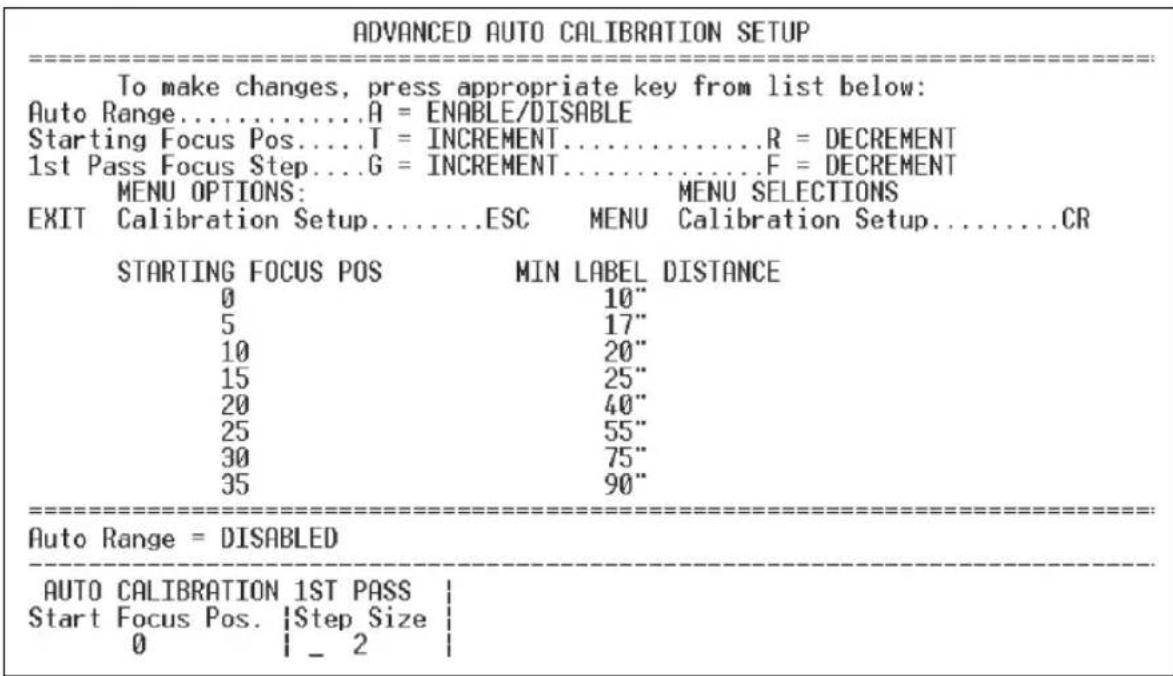
text_image
ADVANCED AUTO CALIBRATION SETUP To make changes, press appropriate key from list below: Auto Range......A = ENABLE/DISABLE Starting Focus Pos....T = INCREMENT......R = DECREMENT 1st Pass Focus Step....G = INCREMENT......F = DECREMENT MENU OPTIONS: MENU SELECTIONS EXIT Calibration Setup......ESC MENU Calibration Setup......CR STARTING FOCUS POS MIN LABEL DISTANCE 0 10" 5 17" 10 20" 15 25" 20 40" 25 55" 30 75" 35 90" Auto Range = DISABLED AUTO CALIBRATION 1ST PASS Start Focus Pos. |Step Size | 0 _ 2Calibration by Embedded Menu
10)Raster/Laser
Contents
Raster/Laser Setup by ESP 10-2
Raster/Laser Serial Commands 10-2
Raster Setup 10-3
Laser Framing 10-7
Raster/Laser by Embedded Menu 10-9
This section explains the setup and adjustments for the raster and laser.
Note: The characters NUL, <, >, and , can only be entered through embedded menus, not through ESP or serial commands.
Note: Raster setup commands in the ESP are accessed from the Read Cycle/Triggering menu or from the Raster/Laser or Calibration menus on the ESP toolbar.
Raster/Laser Setup by ESP
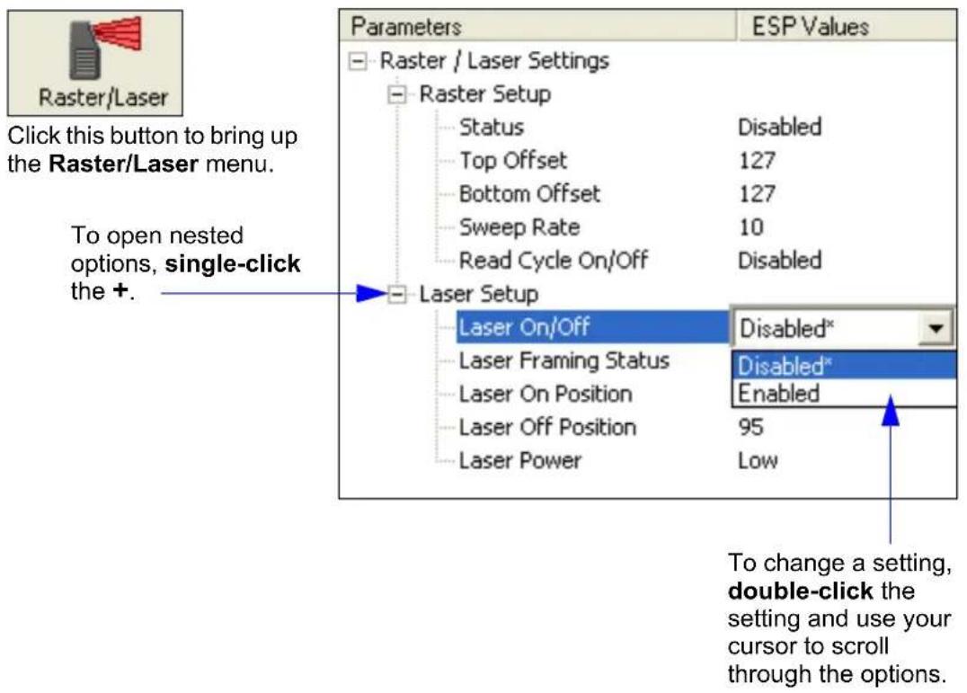
text_image
Raster/Laser Click this button to bring up the Raster/Laser menu. To open nested options, single-click the +. Parameters ESP Values Raster / Laser Settings Raster Setup Status Disabled Top Offset 127 Bottom Offset 127 Sweep Rate 10 Read Cycle On/Off Disabled Laser Setup Laser On/Off Disabled* Laser Framing Status Disabled* Laser On Position Enabled Laser Off Position 95 Laser Power Low To change a setting, double-click the setting and use your cursor to scroll through the options.Raster/Laser Serial Commands
| Command Title Format | |
| Raster | |
| Laser On/Off |
Raster Setup
You can set up and make changes to the scanner's raster parameters in ESP's Read Cycle, Calibration, or Raster/Laser views (preferred).
To access the Raster Setup menu, click the Raster/Laser button and the Raster Setup tab.
Usage:
Raster scanning is useful when symbols vary in placement and a single scan line cannot be counted on to cross the symbol, and for reading stacked symbologies such as PDF417.
Definition:
The user can enable raster scanning and adjust the raster sweep limits and the sweep rate.
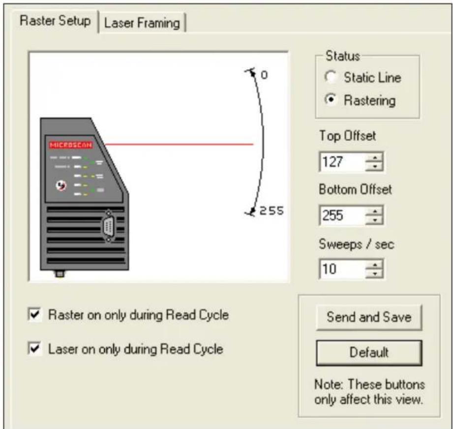
text_image
Raster Setup | Laser Framing | Status Static Line Rastering Top Offset 127 Bottom Offset 255 Sweeps / sec 10 ✓ Raster on only during Read Cycle ✓ Laser on only during Read Cycle Send and Save Default Note: These buttons only affect this view.Note: Changes made in the Raster Setup menu are dynamic; that is, they take effect without saving.
Raster Setup
Raster Status
Definition: When disabled, the raster mirror will park at the top of the raster sweep.
Serial Cmd:
Default: Disabled
Options: 0 = Disabled 1 = Enabled
Note: Raster sweeps are only counted during a read cycle (continuous, triggered, and read rate). Raster sweeps are NOT counted when the raster motor is parked, disabled, set to straight line operation (top and bottom are equal), or when performing a self-calibration.
Top Offset
Definition: Decreasing the Top Offset value causes the top of the raster pattern to move up.
Serial Cmd:
Default: 127
Options: 0 to 255
Bottom Offset
Definition: Increasing the Bottom Offset value causes the bottom of the raster pattern to move down.
Serial Cmd:
Default: 127
Options: 0 to 255
Note: For single scan line operation, set Top Offset equal to Bottom Offset or click on the Static Line option.
Note: Assigning a larger value to Top Offset than Bottom Offset will park the raster mirror in its "home" (default) position.
Raster Sweep Rate
Usage: If your application allows it, a slower sweep rate can produce more scans per second and higher read rates. To determine the minimum read rate for your application, see Raster Picket Fence Calculation on page A-28.
Definition: The raster sweep rate is the number of sweeps per second the raster mirror completes. A sweep is one pass of the raster, up or down. The maximum sweep rate is limited by the size of the arc the raster must move through.
Serial Cmd:
Default: 10
Options: 0 to 30.
The table below shows the maximum speeds at selected raster sweep arcs. To maximize the number of scans per symbol, use the lowest effective sweep rate required for the application.
| Raster Sweep Arc Maximum Sweeps per Second | |
| 0 to 10° 30 | |
| 11 to 20° 20 | |
| 21 to 36° 10 | |
Raster Setup
Read Cycle On/Off
Usage: This feature should only be used when the raster sweep rate is at least twice the required trigger rate ( decoded outputs per second).
Definition: When Read Cycle On/Off is enabled and Laser On/Off is also enabled, the raster mirror stops at top offset at the end of triggered read cycle.
Serial Cmd:
Default: Disabled
Options: 0 = Disabled 1 = Enabled
Laser Framing
To access the Laser Framing menu, click the Raster/Laser button and the Laser Framing tab.
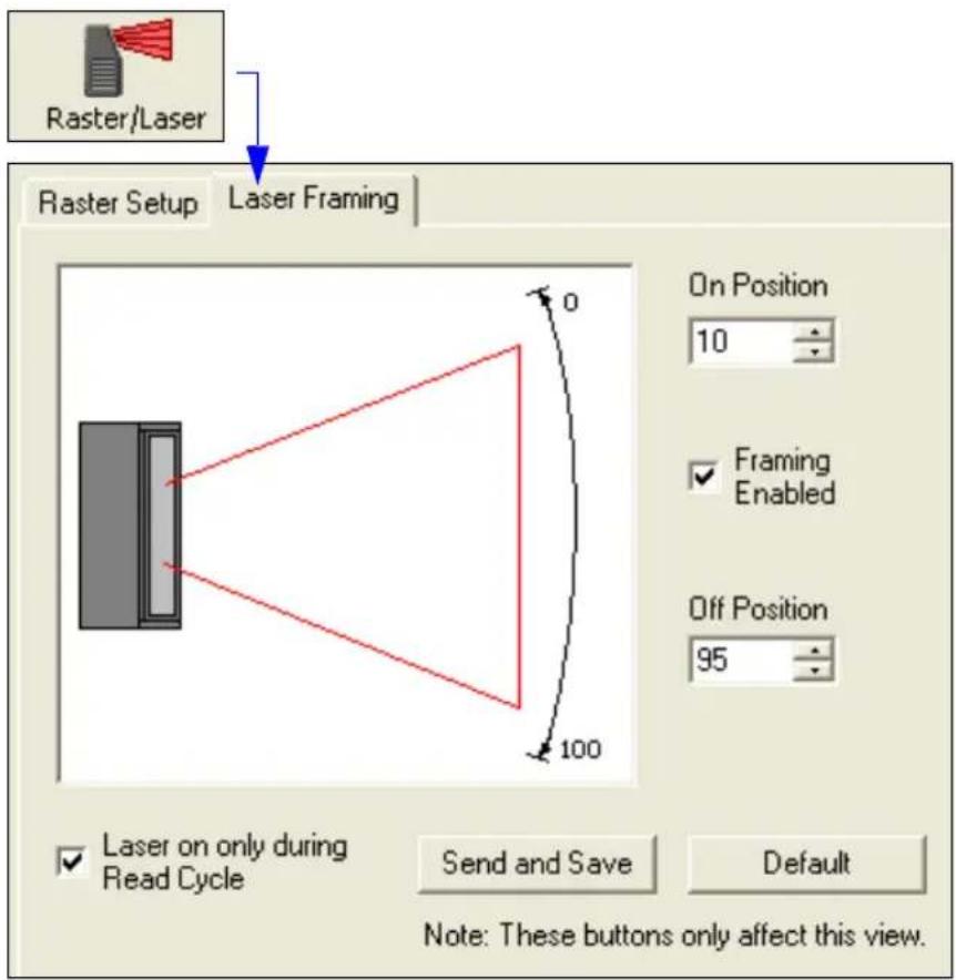
text_image
Raster/Laser Raster Setup Laser Framing On Position 10 Framing Enabled Off Position 95 Laser on only during Read Cycle Send and Save Default Note: These buttons only affect this view.Laser On/Off Status
Usage: Laser On/Off extends the life of the laser. It is useful where there are significant time gaps between symbols. It also provides visual confirmation of a read cycle timeout and minimizes laser exposure to people.
Definition: When enabled, the laser is ON only during the read cycle. When disabled, the laser operates continuously.
Serial Cmd:
Default: Disabled
Options: 0 = Disabled 1 = Enabled
Note: A serial or external trigger must be enabled for Laser On/Off to take effect.
Note: Laser On/Off is not recommended when New Trigger is enabled, since the laser will effectively remain on continuously.
Laser Framing
Laser Framing Status
Usage: Useful in avoiding highly reflective objects, for filtering out unwanted signals, or avoiding the wrong symbols.
Definition: Sets the length of time the laser is ON during each scan so that only a selected portion of the scan width is effectively scanned.
Serial Cmd:
Default: Disabled
Options: 0 = Disabled 1 = Enabled
To adjust laser framing, click the Raster button, click the Laser Setup tab, and click the Laser On and Laser Off arrows up or down.
When Laser Framing is not enabled, the scan beam sweeps across the full scan width. When enabled, the laser remains OFF during the Laser Off Time beginning at the start of the scan beam sweep and turns ON for the duration of the Laser On Time.
Laser On Position
Definition: Measured in increments equal to 1/100th of total scan width.
Serial Cmd:
Default: 10
Options: 10 to 90
Laser Off Position
Definition: Measured in increments equal to 1/100th of total scan width.
Serial Cmd:
Default: 95
Options: 15 to 95
Laser Power
Usage: Used to optimize read performance at different distances. Typically higher power is used at greater distances.
Definition: Allows the user or calibration routine to select laser power setting.
Serial Cmd:
Default: High Power (low or medium density scanner)
Options: 0 = Low (3.0 mW) 1 = Medium (3.25 mW) 2 = High (3.5 mW)
Raster/Laser by Embedded Menu
To access the Raster/Laser Framing menu, send <@> to open the Calibration Setup menu and type the number 2.
| RASTER/LASER FRAMING SETUP MENU | ||||
| To make changes, press appropriate key from list below: RASTER SETTINGS | ||||
| INCR. | DECR. | RANGE | STATUS | |
| Top Offset..... | T ..... | R | 0-255 | Raster Status.....E |
| Bottom Offset... | B ..... | U | 0-255 | Raster On/Off.....F |
| Sweep Rate..... | S ..... | A | 0-30 | |
| LASER SETTINGS | ||||
| INCR. | DECR. | RANGE | STATUS | |
| Laser Off Time.. | P ..... | O | 0-255 | Laser Framing Status.....M |
| Laser On Time... | L ..... | K | 0-255 | Laser On/Off.....N |
| MENU OPTIONS: EXIT Calibration Setup.....ESC | MENU SELECTIONS Calibration Setup.....CR | |||
| Raster Status = ENABLED Laser Framing = DISABLED | Raster On/Off = DISABLED Laser On/Off = DISABLED | |||
| RASTER | | LASER FRAMING | Top | Bottom | Sweep | Off | On | Offset | Offset | Rate | | Time | Time | _127 | 127 | 10 | | 0 | 255 | 0 % | ||||
Raster Settings
Type the letter T to increment the Top Offset and an R to decrement. Notice that the Top Offset reading at the bottom of the menu changes accordingly.
Type the letter B to increment the Bottom Offset and V to decrement.
Sweep Rate, Raster Status, and Raster On/Off are explained more fully in Raster Setup on page 10-3.
Laser Settings
Laser settings are also dynamically updated at the bottom of the menu.
Full instructions and menus for laser operations can be found in Laser Framing on page 10-7. Press the enter key (CR) to return to the main calibration menu or ESC to leave the Auto Calibration Setup menu entirely.
Raster/Laser by Embedded Menu
Terminal
Contents
Terminal Window.... 11-2
Find.... 11-3
Send 11-4
Macros....11-5
Terminal Window Menus.... 11-6
This section describes the Terminal window and macro functions.
Note: The characters NUL, <, >, and , can only be entered through embedded menus, not through ESP or serial commands.
Terminal Window
Terminal Window
Click this button to bring up the Terminal view.
The following window will appear:
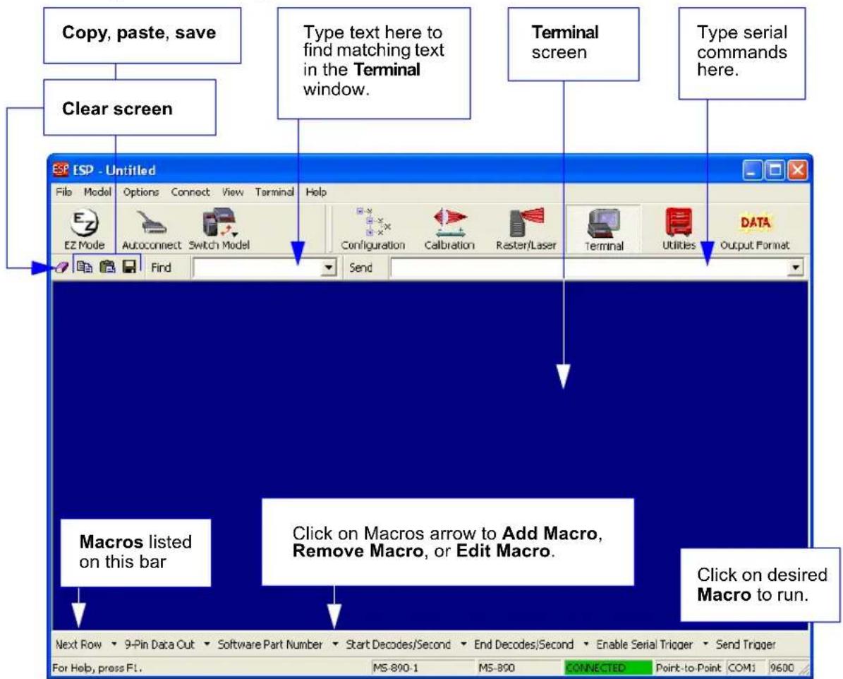
text_image
Copy, paste, save Clear screen Type text here to find matching text in the Terminal window. Terminal screen Type serial commands here. Find Send MACros listed on this bar Click on Macros arrow to Add Macro, Remove Macro, or Edit Macro. Click on desired Macro to run. Next Row 9-Pin Data Out Software Part Number Start Decodes/Second End Decodes/Second Enable Serial Trigger Send Trigger For Help, press FL. MS-890-1 MS-890 CONNECTED Point-to-Point COM: 9600The Terminal screen allows you to send serial commands to the scanner by using Macros, by copying and pasting, or by typing commands in the Send text field.
The Terminal screen also displays symbol data or information from the scanner.
You can also right-click on the Terminal screen to bring up a menu of further options.
Find
The Find function allows you to enter text strings to be searched for in the Terminal window. For example, a series of symbols have been scanned into the Terminal view and you want to determine if a particular symbol whose data begins with "ABC" has been read.
- Type "ABC" into the Find box.

text_image
Find ABC- Press Enter.
The first instance of "ABC" will be highlighted in the Terminal window.
- Click the Find button to the right of the text field to locate additional instances of "ABC".
Send
Send
The Send function in ESP's Terminal allows you to enter serial commands and then send them to the scanner.
- Type the command into the Send box.

text_image
Configuration Calibration Raster/Laser Terminal Utilities DATA Output Format Send <@CAL>- Press Enter.
- Click the Send button to the left of the text field to send.
Macros
Macros can be stored in a macro selection bar, edited in a separate window, and executed by clicking on the macro name.
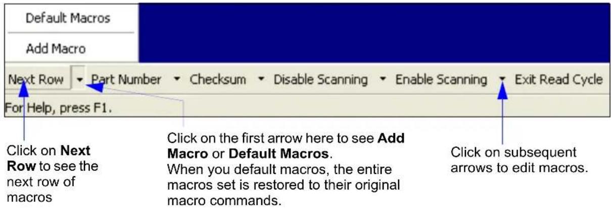
text_image
Default Macros Add Macro Next Row Part Number Checksum Disable Scanning Enable Scanning Exit Read Cycle For Help, press F1. Click on Next Row to see the next row of macros Click on the first arrow here to see Add Macro or Default Macros. When you default macros, the entire macros set is restored to their original macro commands. Click on subsequent arrows to edit macros.When you click on the macro name, the macro is executed in the Terminal window. If this is a command, it is sent to the scanner at the same time that it is displayed.
Editing a Macro
When you click the arrow next to any macro and select Edit, the following appears:
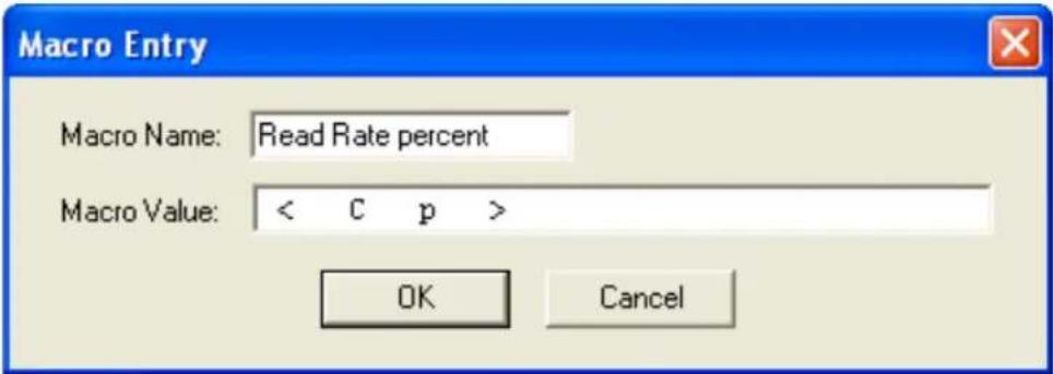
text_image
Macro Entry Macro Name: Read Rate percent Macro Value: < C p > OK CancelYou can edit an existing macro or type in the Macro Name text field and define it in the Macro Value text field. Click OK.
Terminal Window Menus
Right-click on the Terminal window to display the following menu:
| CopyPaste |
| ClearSelect AllSave... |
| Change Font...Change Echo Font...Disable EchoChange Background Color ▶Non-Printable Characters ▶Default Settings |
| Keyboard Macros... |
- Copy selected text to clipboard.
- Paste from Terminal or computer text.
- Clear all text in Terminal window.
- Select All text in the Terminal window.
- Save... brings up a save as dialog box.
- Change Font... of data text, brings up a text dialog.
- Change Echo Font... to change typed in text or commands.
- Change Background Color of Terminal window.
- Default Settings changes all the above back to default settings.
Terminal Dropdown Menu
The dropdown Terminal menu has Capture Text and Save Current Text functions, as well as the functions defined above.
| Terminal | Help |
| Capture Text...Save Current Text... | |
| Change Font...Change Echo Font...Disable EchoChange Background Color ▶Non-Printable Characters ▶Default Settings | |
| Find Next | F3 |
| Find Previous | Shift+F3 |
| Keyboard Macros... | |
- Capture lets you append data in real time to a text file of your choice. While in operation, the text file cannot be opened. You can select Pause to interrupt the capture flow or Stop to end the flow and open the file.
- Save Current Text... saves all text in the Terminal window to a text file of your choice.
121 Utilities
Contents
Serial Utility Commands 12-2
Read Rate 12-4
Counters 12-6
Device Control 12-8
Differences from Default.... 12-10
Master Database 12-11
Digital Bar Code 12-16
Firmware....12-17
Autodiscriminate 12-19
Scanner Status Requests.... 12-20
Utility commands are generally commands that are performed during scanner operations to check read rates, determine read rates or perform miscellaneous operations on scanner hardware. Serial utility commands are not prefaced with a K and a numeric code, nor do they require an initialization command ( and
Note: The characters NUL, <, >, and , can only be entered through embedded menus, not through ESP or serial commands.
Serial Utility Commands
| Command Type Command Name | ||
| Read RateEnter Read Rate Test | ||
| Enter Multisymbol | Read Rate Test | |
| Enter Percent Test | ||
| Enter Multisymbol | Percent Test | |
| Extended Read Rate | ||
| Enter Percent | PDF Read Rate Test | |
| Exit Read Rate and | Percent Test | |
| CountersNo Read Counter | ||
| No Read Counter | Reset | |
| Trigger Counter | ||
| Trigger Counter Reset | ||
| Good Read/Match | Counter | |
| Good Read/Match Counter Reset | ||
| Mismatch Counter | ||
| Mismatch Counter | Reset | |
| Device Control | Enable Laser Scanning (Laser On) | |
| Disable Laser Scanning (Laser Off) | ||
| Motor On | ||
| Motor Off | ||
| Programmable Output 1 Pulse | ||
| Programmable Output 2 Pulse | ||
| Programmable Output 3 Pulse | ||
| Matchcode | Enable Matchcode Type | |
| Disable Matchcode | Type | |
| Store Next Symbol | to Database Index 1 | |
| Master Database | Store Next Symbol to Database Index n | |
| Download Master Symbol Data to Database Index n | ||
| Display Master Symbol Data from Database Index n | ||
| Delete Master Symbol from Database Index n | ||
| Firmware | Display Checksums for Boot Code and Application Code | |
| Display Checksum for Boot Code | ||
| Display Checksum for Application Code | ||
| Display Checksum for Raster Code | ||
| Display Boot Code | and Application Code Part Number | |
| Display Boot Code Part Number | ||
| Display Application Code Part Number | ||
| Symbologies | Autodiscriminate All Symbologies | |
| Enable Code 39 Only | ||
| Enable Codabar Only | ||
| Enable Interleaved | 2/5 Only | |
| Trigger | Serial Trigger Character | |
Utilities
| Default/Reset/Save | < A > Reset (does not save for Power-On) |
| < An > Reset and Read Flash Parameters | |
| < Z > Save Current Settings for Power-On | |
| Status Requests <?> Status Byte | |
Read Rate
You can access Read Rate from the Utilities menu.
To start or end a read rate test, right-click Read Rate and select Start or Stop.
To change from percent read rate to decodes per second, first end the read rate by selecting Stop, then right-click select Decodes/Sec.
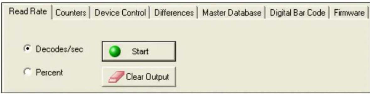
text_image
Read Rate | Counters | Device Control | Differences | Master Database | Digital Bar Code | Firmware | Decodes/sec Start Percent Clear OutputRead Rate by Serial Command
Enter Single Symbol Percent Test
Sending
Enter Multisymbol Percent Test
Sending
Enter Single Symbol Read Rate Test
Sending
Enter Multisymbol Read Rate Test
Sending
Enter Percent PDF Read Rate Test
Sending
Enable PDF Information
Sending the
This feature can be disabled by using the exit read rate command
Enable Extended Read Rate Test for Single and Multisymbol
Sending
Extended Mode instructs the scanner to output the decode rate, the symbol data, and the transition data.
The example below shows output with Postamble enabled and defined as Carriage Return/Line Feed.
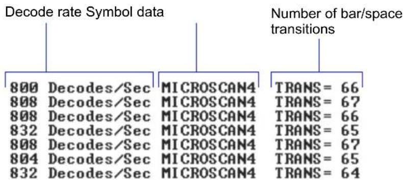
other
| Category | Value | |---|---| | Decode rate Symbol data | 800 Decodes/Sec MICROSCAN4 | | Decode rate Symbol data | 808 Decodes/Sec MICROSCAN4 | | Decode rate Symbol data | 808 Decodes/Sec MICROSCAN4 | | Decode rate Symbol data | 832 Decodes/Sec MICROSCAN4 | | Decode rate Symbol data | 808 Decodes/Sec MICROSCAN4 | | Decode rate Symbol data | 804 Decodes/Sec MICROSCAN4 | | Decode rate Symbol data | 832 Decodes/Sec MICROSCAN4 | | Number of bar/space transitions | TRANS = 66 | | Number of bar/space transitions | TRANS = 67 | | Number of bar/space transitions | TRANS = 66 | | Number of bar/space transitions | TRANS = 65 | | Number of bar/space transitions | TRANS = 67 | | Number of bar/space transitions | TRANS = 65 | | Number of bar/space transitions | TRANS = 64 |Note: The
End Read Rate Test
Sending
Counters
Counters
Counter commands can be a numeric value from 00000 to 65535. After reaching the maximum numeric limit of 65,535, the counter will automatically rollover and start counting again at 00000 and report any errors. To obtain the cumulative total of counts after the rollover has occurred, add 65,536 per each rollover (the scanner does not keep track of the number of rollovers) to the current count.
Note: All counter values will be lost if power is recycled to the scanner or the scanner receives a reset or save command.
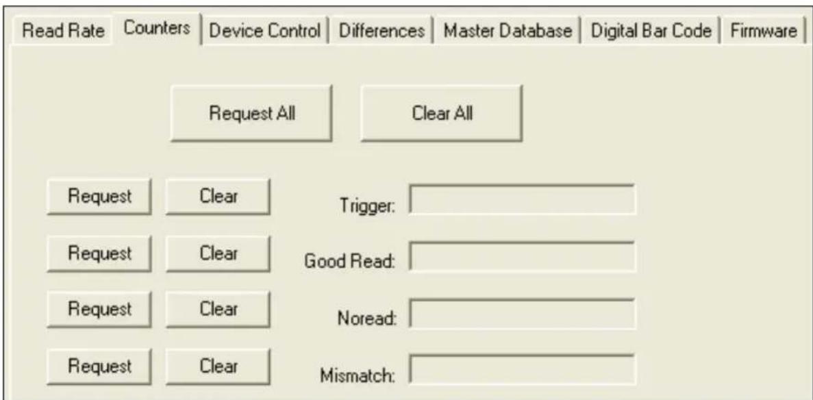
text_image
Read Rate Counters Device Control Differences Master Database Digital Bar Code Firmware Request All Clear All Request Clear Trigger: Request Clear Good Read: Request Clear Noread: Request Clear Mismatch:Counters by Serial Command
No Read Counter
Sending
No Read Counter Reset
Sending
Trigger Counter
Sending
Trigger Counter Reset
Sending sets the trigger counter to 00000.
Good Read/Match Counter
Sending
Good Read/Match Counter Reset
Sending
Mismatch Counter
With Matchcode enabled, sending
Mismatch Counter Reset
Sending
Device Control
Device Control is accessible from the Utilities menu.
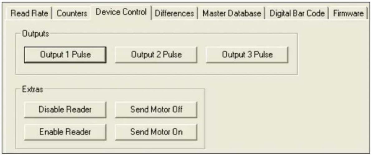
text_image
Read Rate | Counters | Device Control | Differences | Master Database | Digital Bar Code | Firmware | Outputs Output 1 Pulse Output 2 Pulse Output 3 Pulse Extras Disable Reader Send Motor Off Enable Reader Send Motor OnDevice Control by Serial Command
Enable Laser Scanning
Sending
Note: Enable Laser Scanning does not relate to Laser On/Off command.
Disable Laser Scanning
Sending will turn the laser off and end the current read cycle. This feature is useful during extended periods of time when no symbols are being scanned or the scanner is being configured. Disabling laser scanning will not affect any downloaded commands to the scanner.
Note: Disable Laser Scanning does not relate to Laser On/Off, which, when enabled, also turns off the laser but only between read cycles.
Motor On
Sending
Note: The spinning mirror reaches full speed after a short time delay.
Motor Off
Sending
Note: Laser turns off whenever motor is off.
Output 1
Sending
Output 2
Sending
Output 3
Sending
Differences from Default
Clicking the Differences from Default button will cause ESP to check all stored configuration settings and compare them to default settings. All settings that are different than default will appear in the left column (shown below), and descriptions of those settings will appear in the right column.
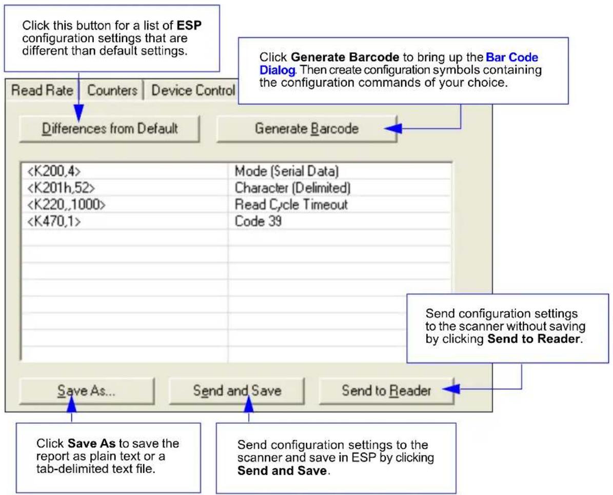
flowchart
graph TD
    A["Click this button for a list of ESP configuration settings that are different than default settings."] --> B["Read Rate"]
    A --> C["Counters"]
    A --> D["Device Control"]
    B --> E["Differences from Default"]
    C --> E
    D --> E
    E --> F["Generate Barcode"]
    F --> G["Send configuration settings to the scanner without saving by clicking Send to Reader."]
    G --> H["Send and Save"]
    H --> I["Save As..."]
    I --> J["Send and Save"]
    J --> K["Send to Reader"]
    K --> L["Send configuration settings to the scanner and save in ESP by clicking Send and Save."]
- To create a symbol containing any of the command settings in the table, click Generate Barcode. This will bring up the Bar Code Dialog.
- To save the Differences from Default report, either as plain text or as a tab-delimited text file, click Save As.
- Click Send and Save to send the settings to the scanner and save them, or Send to Reader to send the settings without saving them.
Important: The use the Differences from Default feature, you must connect to the scanner and Receive Reader Settings via the Send/Recv button on the toolbar.
Master Database
Important: Master Database is used only for comparing entire symbols, when Sequential and Wild Card are NOT enabled, and Start Position is equal to 0.
Master Database Overview
Usage: Used where more than one master symbol is required, as in a Multisymbol setup, for matching and other matchcode operations.
Definition: Allows you to define up to 10 master symbols as the master symbol database, which can be entered by keyboard, scanned in, displayed, or deleted by serial or ESP commands.
- Click the Master Database tab.
- Set the Master Symbol Database Size.
- Select database index you want to enter the master symbol.
-
Do one of the following to enter master symbol data:
-
Double-click the index row to type data directly into index. (See Enter Master Symbol Data on page 12-13.)
- Click Read Symbol into Selected Index to enter the next decoded symbol.
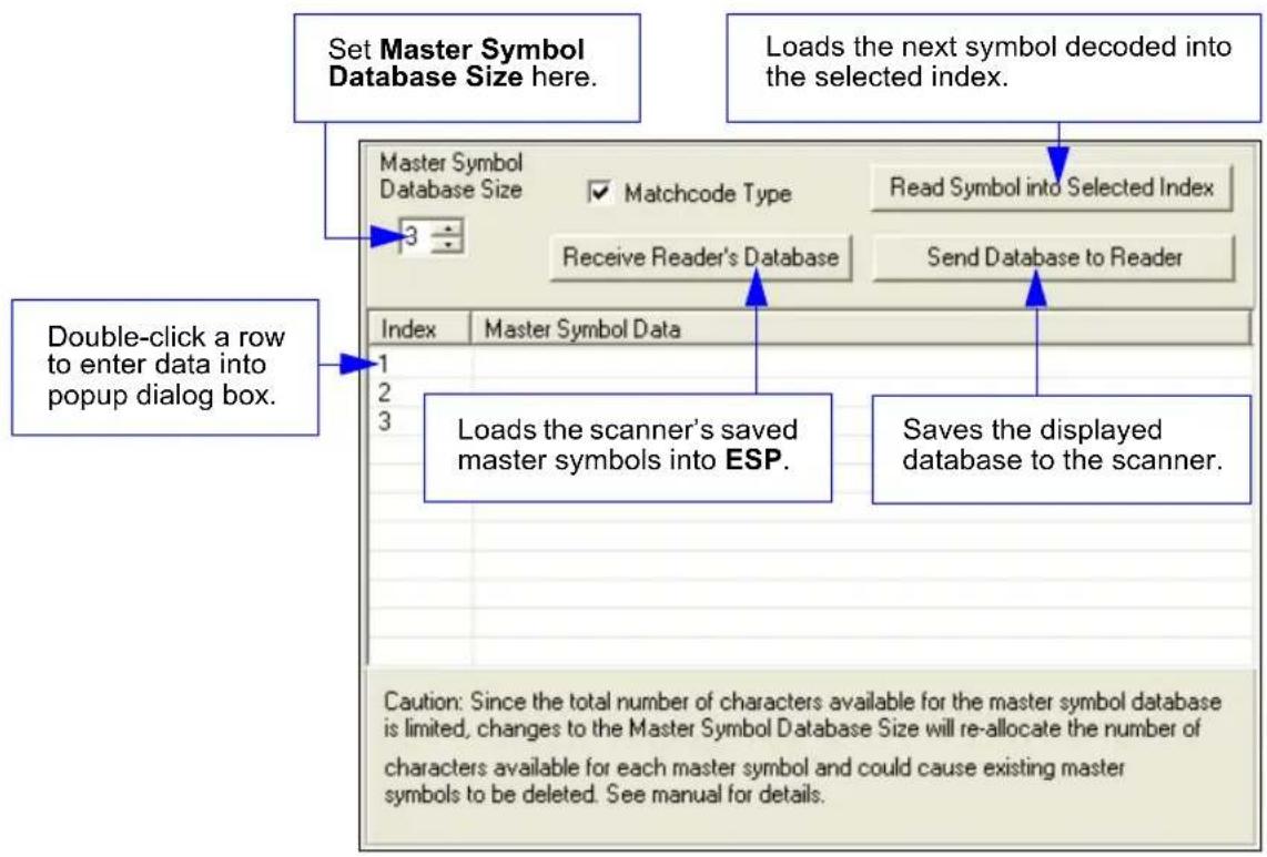
text_image
Set Master Symbol Database Size here. Loads the next symbol decoded into the selected index. Master Symbol Database Size Matchcode Type Read Symbol into Selected Index Receive Reader's Database Send Database to Reader Index Master Symbol Data 1 2 3 Double-click a row to enter data into popup dialog box. Loads the scanner's saved master symbols into ESP. Saves the displayed database to the scanner. Caution: Since the total number of characters available for the master symbol database is limited, changes to the Master Symbol Database Size will re-allocate the number of characters available for each master symbol and could cause existing master symbols to be deleted. See manual for details.Master Database
Master Symbol Database Size
Definition: Master Symbol Database Size allows you to select 1 to 10 master symbols for the master symbol database.
ESP: First set the number of master symbols you want to include by double-clicking Database Size and entering the number.
Serial Cmd:
Default: 1
Options: 1 to 10
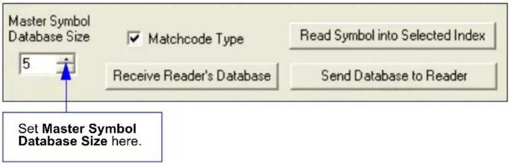
text_image
Master Symbol Database Size 5 Matchcode Type Read Symbol into Selected Index Receive Reader's Database Send Database to Reader Set Master Symbol Database Size here.Enter Master Symbol Data
Definition: Allows you to enter master symbol data for a specific master symbol index number (1 to 10), provided the index number is not larger than the number of symbols enabled by the Master Symbol Database Size. For example, if Master Symbol Database Size is set to 2, you will not be able to enter data for symbols 3 through 10.
ESP: Double-click on the index row.
Serial Cmd:
Default: 1, (blank)
Options: 1 to 10, any combination of ASCII text up to the maximum indicated in the Maximum Characters for Master Symbol Database table below.
For example, to enter data for master symbol 9, after making certain that master symbol database size is enabled for 9 or more symbols (see Master Symbol Database Size on page 12-12), send
Caution: Since the total number of characters available for the master symbol database is 2710 changes to the Master Symbol Database Size will re-allocate the number of characters available for each master symbol and could cause existing master symbols to be deleted (except master symbol #1 unless it also exceeds the size limitation).
The table below specifies the maximum number of characters available to each symbol according to the number of master symbols defined, from 1 through 10.
See Master Symbol Database Size on page 12-12.
Maximum Characters for Master Symbol Database
| Number of Master Symbols | Maximum Characters | Number of Master Symbols | Maximum Characters |
| #1 20452710 | #6 340 | ||
| #2 1022 #7 291 | |||
| #3 681 #8 254 | |||
| #4 510 #9 226 | |||
| #5 408 #10 203 | |||
Request Master Symbol Data
Definition: Returns master symbol data for any enabled master symbols from 1 to 10.
For example, to request master symbol # 5, enter
Serial Cmd: Send
Returns all master symbols if no number is added before the question mark.
Options: 1 to 10
Delete Master Symbol Data
Definition: This command will delete the current master symbol data.
ESP: You can delete master symbol data for any master symbol by erasing the data in the Master Database popup dialog (under Output Format) and clicking OK.
Serial Cmd:
Read Next Symbol as Master Symbol
Definition: After you've set the size in the database, you can order the scanner to read the next symbol as the master symbol.
ESP: In the Master Database tab, under the Output Format menu:
- Select the master symbol index number in which you want to store the symbol data.
- Click Read Symbol into Selected Index.
Serial Cmd:
To store the next symbol scanned as master symbol #1 send:
Options: 1 to 10
Note: Utility commands are not accessible by embedded menus.
Digital Bar Code
When you click the Digital Bar Code tab and the Start button, a digitized representation of the candidate symbol will appear.
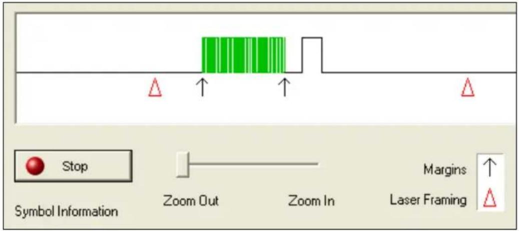
text_image
Stop Symbol Information Zoom Out Zoom In Margins Laser Framing ↑ △This routine is useful for conveying a sense of the symbol's readability and graphically indicating bad or unreadable portions of symbols or extraneous "noise". A green waveform indicates a decoded symbol; a red waveform indicates an undecoded symbol or other object. The red triangles represent the width of the scan beam relative to the symbol. The upward pointing arrows indicated the symbol's margin.
Zoom In, Zoom Out
You can zoom in by sliding the Zoom lever to the right. You may have to scroll right or left to locate your symbol, but the results will be striking.
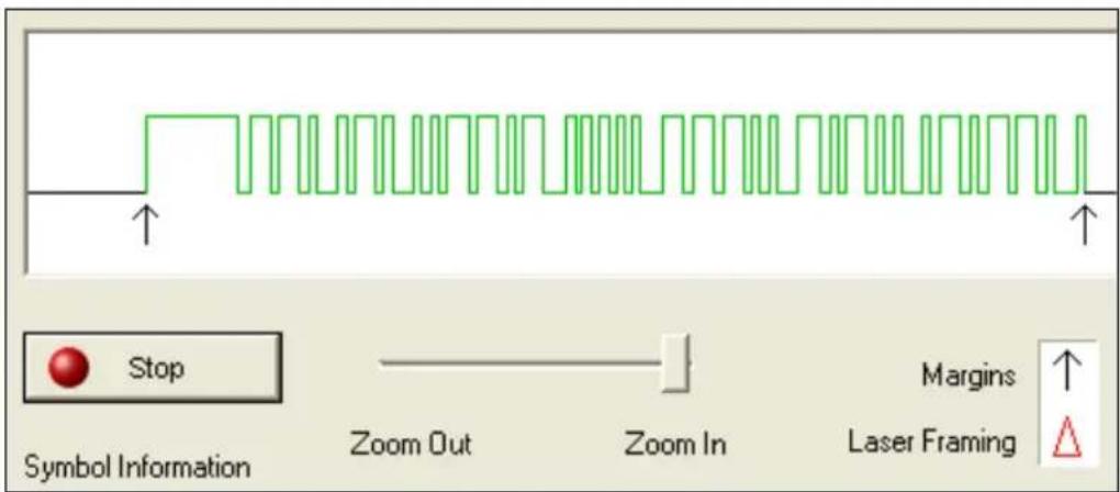
text_image
Stop Symbol Information Zoom Out Zoom In Margins Laser FramingFirmware
Firmware Update
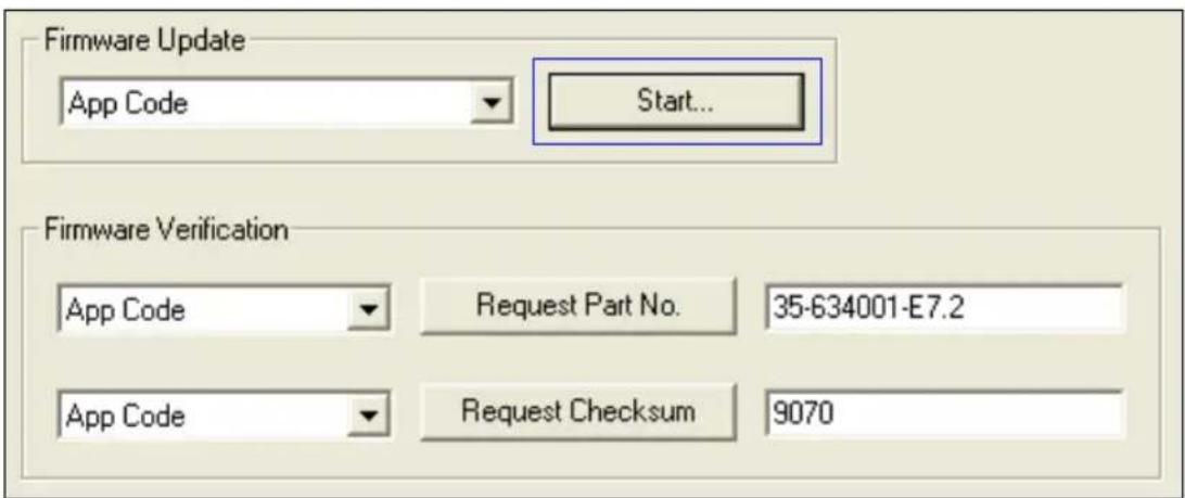
text_image
Firmware Update App Code Start... Firmware Verification App Code Request Part No. 35-634001-E7.2 App Code Request Checksum 9070Firmware Update is used to download application code to the scanner.
Application code versions are specific to your scanner. Consult with your sales representative before downloading application code. If needed, an application code will be sent to you in the form of a *.mot file.
To download application code:
- First make sure the host is connected to your scanner.
- Apply power to the scanner.
- Before updating, verify the current firmware (see Firmware Verification (Part Number) below.)
- Click in the Firmware Update text box and select the file type you want to download. This will open a file locator box.
- Navigate to the appropriate file (a *.mot file) and open the file.
As application code begins to download to the scanner, the scanner will go silent, the scanner's RDY and GD/RD LEDs will flash intermittently, and a progress indicator at the bottom of the ESP window will let you know when the download is complete.
Caution: Do not interrupt power or disconnect the host cable while download is in progress.
Firmware
Firmware Verification (Part Number)
You can send a request for the scanner's current firmware part numbers using this dialog:
- From the Utilities menu you can access Firmware Verification from the Firmware tab.
- Select the firmware code you want to check and click Request Part No. to see the associated part number.
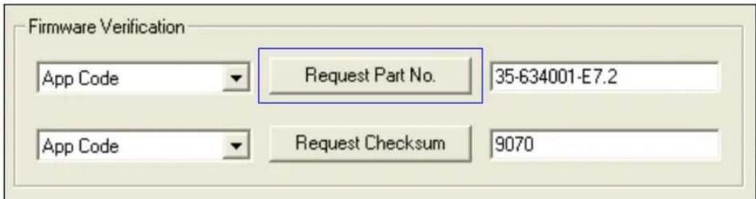
text_image
Firmware Verification App Code ▼ Request Part No. 35-634001-E7.2 App Code ▼ Request Checksum 9070Part Number by Serial Command
Upon sending <#> the scanner returns software part numbers for application code <#a/____> and boot code <#b/____>.
Individual part numbers for Application Code and Boot Code are returned when their respective commands <#a> and <#b> are sent.
Firmware Verification (Checksum)
A checksum verifies a scanner's flash memory.
- From the Utilities menu you can access Firmware Verification from the Firmware tab.
- Select the firmware code you want to check and click Request Checksum to see the associated part number.
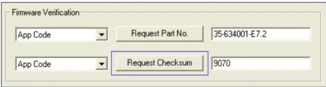
text_image
Firmware Verification App Code ▼ Request Part No. 35-634001-E7.2 App Code ▼ Request Checksum 9070Checksum by Serial Command
Upon sending <!> the scanner returns two 4-digit hex numbers that are the check sums for boot code and the application code.
Individual checksums for Boot Code and Application Code are returned when their respective commands <!b> and <!a> and <!r> are sent.
Autodiscriminate
You can enable most or specific symbol types by the following operational commands.
Default: Code 39 (only)
Options:
Enables most symbol types.
Enable Code 39 only
Enable | 2/5 only
Scanner Status Requests
Status Byte
The scanner responds to a status request <?> with a two character hex value, for example <?/22>. To determine the status:
- Look up the binary conversion in the hex-to-binary table.
For example, the first 2 in binary would be 0 0 1 0 as read from binary digits 3 through 0; the second 2 the binary digits 7 through 4 which is also 0 0 1 0.
- Next, enter your binary values in the "Scanner Status" table, in the "Binary" column next to the appropriate bit.
| Bit Binary Scanner Status | |
| 0 0 Command error detected | |
| 1 1 Command received | |
| 2 0 Communication error detected | |
| 3 0 Flash sector unprotect failure | |
| 4 0 Host/Aux port buffer overflow | |
| 5 1 Scanner is in a read cycle | |
| 6 0 Software Watchdog reset | |
| 7 0 Hardware Watchdog reset |
- Under "Binary," interpret 1s as true and the 0s as not true. For example, bit 1 has a 1 in the "Binary" column, indicating "Command Received." Bit 5 is also a 1 indicating that the "Scanner is in a read cycle."
| Hex Value | Binary Bit Digits | |||
| 7 | 6 | 5 | 4 | |
| 3 | 2 | 1 | 0 | |
| 0 | 0 | 0 | 0 | 0 |
| 1 | 0 | 0 | 0 | 1 |
| 2 | 0 | 0 | 1 | 0 |
| 3 | 0 | 0 | 1 | 1 |
| 4 | 0 | 1 | 0 | 0 |
| 5 | 0 | 1 | 0 | 1 |
| 6 | 0 | 1 | 1 | 0 |
| 7 | 0 | 1 | 1 | 1 |
| 8 | 1 | 0 | 0 | 0 |
| 9 | 1 | 0 | 0 | 1 |
| A | 1 | 0 | 1 | 0 |
| B | 1 | 0 | 1 | 1 |
| C | 1 | 1 | 0 | 0 |
| D | 1 | 1 | 0 | 1 |
| E | 1 | 1 | 1 | 0 |
| F | 1 | 1 | 1 | 1 |
Extended Status
The scanner responds to an extended status request <?1> with several fields, for example: <?1/20><35-558002-10,35-558001-12,F6D4,20C5,02D3,02D3>.
These represent, in order: the status byte discussed above, the boot part number(35-558002-10), the application part number (35-558001-12), boot checksum (5F6D4), app checksum (02D3), RAM parameter checksum (02D3), and flash parameter checksum (02D3).
All Commands Status
This is the fastest way to learn the scanner's current configuration. Sending this request will return the current settings of all commands, starting with the lowest K command value and ending with the highest K command value.
Single Command Status
This request will return the value of the variables associated with the requested K command. The request of a single entry of a database command cannot exceed the number of database slots for the specific command.
All Command Descriptions
This request will return all current descriptions of every K command, starting with the lowest K command value and ending with the highest K command value.
Single Command Description
This request returns the basic functional description of all fields in the requested K command.
All Command Ranges
This request will return the current settings of all commands within the user-defined range, starting with the lowest user-defined K command value and ending with the highest user-defined K command value.
Single Command Range
This request will return the value range and storage type description of all fields in the requested K command.
Single Command Wildcard
This request will return the requested K command's status, description, and range for all parameters.
Single Command Default
This request will default a single K command for the user, provided that the requested K command has user-defined parameters (rather than factory-defined parameters).
Scanner Status Requests
Output Format
Contents
Output Format Serial Commands.... 13-2
Output Format Status 13-3
Format Assign 13-4
Format Extract.... 13-5
Format Insert 13-7
Output Filter Configuration 13-9
Number of Filters.... 13-14
This section explains how to control the formatting and filtering of decoded symbol data for output.
Output Format Serial Commands
Output Format Serial Commands
Command Title Command Format
| Format Extract | |
| Format Insert | |
| Format Assign | |
| Format Status | |
| Output Filter Configuration | |
| Number of Filters |
Output Format Status
Definition: This is a global enable/disable parameter. In order to use formatting you must set up the format using the insert and extract commands, and you must also assign a symbol to format using the Format Assign command.
Serial Cmd:
Default: Disabled
Options: 0 = Disabled
1 = Enabled
Output Format Status Disabled
When Format Status is set to Disabled, output formatting is globally disabled.
Output Format Status Enabled
When Format Status is set to Enabled, output formatting is enabled. However, Format Assign, Format Insert, and Format Extract must be properly set up as well.
Output Format Status by ESP
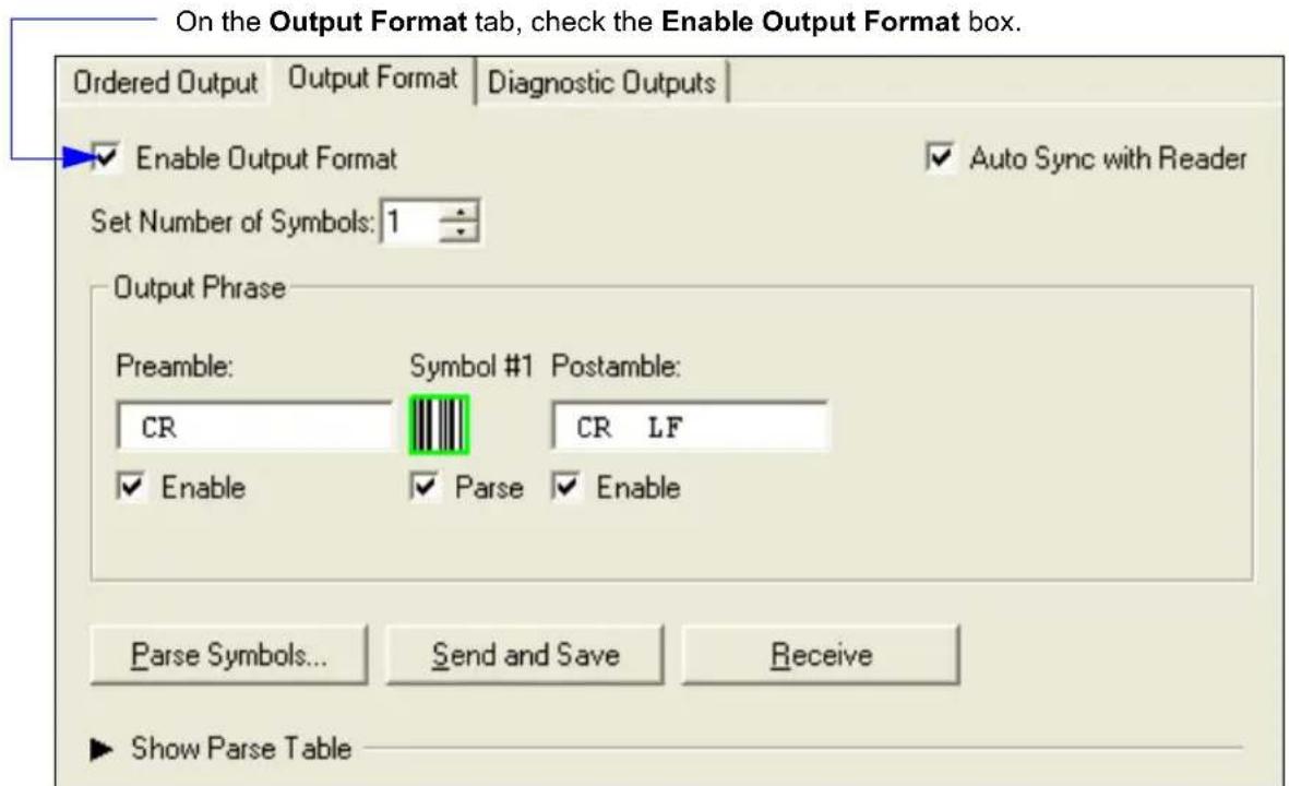
text_image
On the Output Format tab, check the Enable Output Format box. Ordered Output | Output Format | Diagnostic Outputs | Enable Output Format Auto Sync with Reader Set Number of Symbols: 1 Output Phrase Preamble: Symbol #1 Postamble: CR CR LF Enable Parse Enable Parse Symbols... Send and Save Receive Show Parse TableFormat Assign
Format Assign
Symbol Number
Definition: Symbol Number refers to the number of the symbol to which output formatting will apply. For example, if you wish to enable user-defined formatting to symbol # 2 in a multisymbol read cycle, you would send the command
Serial Cmd:
Options: 1 to 12
1 = Formatted output status for symbol # 1.
2 = Formatted output status for symbol # 2.
12 = Formatted output status for symbol # 12.
Format Assign Status
Definition: Status refers to the user-defined formatting of a selected symbol position in the read cycle result. Note that there is also a global formatting "enable" command that must be set for the formatting to be applied.
Serial Cmd:
Default: Disabled
Options: 0 = Disabled
1 = Enabled (Assign parameters to specified symbol)
Format Assign by ESP
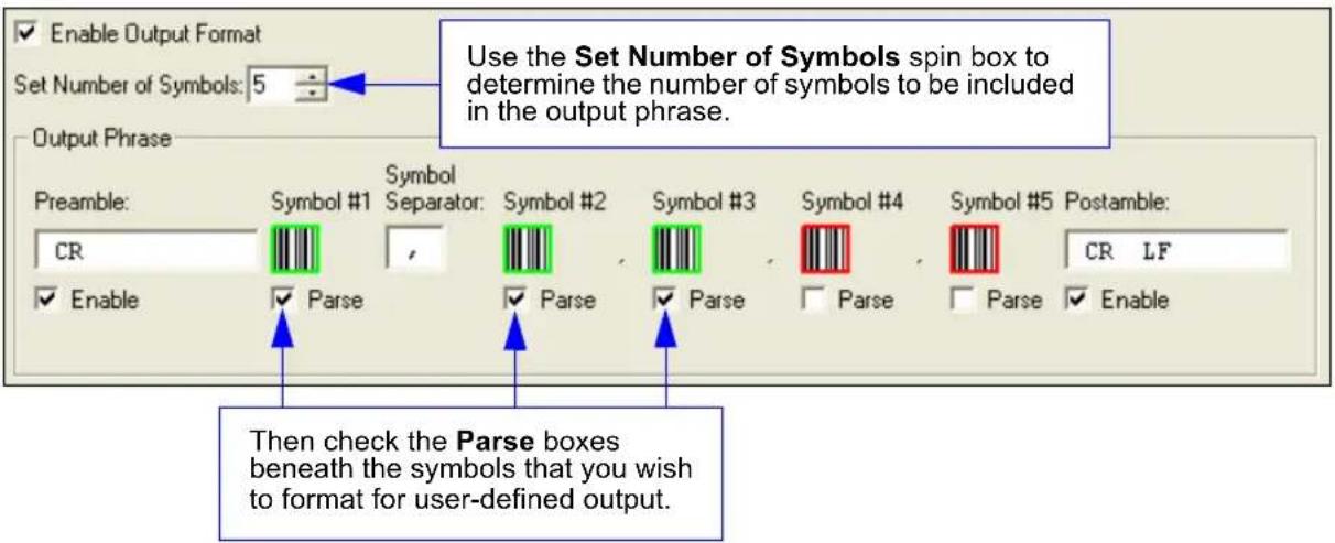
text_image
Enable Output Format Set Number of Symbols: 5 Output Phrase Preamble: CR Symbol #1 Symbol Separator: Symbol #2 Symbol #3 Symbol #4 Symbol #5 Postamble: CR LF Enable Parse Parse Parse Parse Parse Enable Then check the Parse boxes beneath the symbols that you wish to format for user-defined output.Format Extract
Output Index
Definition:
Output Index refers to the database entry you wish to modify with this command. A formatted output is built by extracting data from a symbol's original data output and/or inserting user-defined characters.
It may be helpful to think of individual indexes as positions in the final formatted output you wish to build. Starting with index # 1, enter either an extract or insert command to begin building your desired output string. Then, with the next index number, enter either an extract or insert command to continue building the output string. Continue this process until you are finished building the string.
Serial Cmd:
Options: 1 to 100
Start Location
Definition:
Defines the location within the symbol data where the character extraction will begin. The first character extracted will also be the first character in the sequence displayed in user-defined output.
Serial Cmd:
Default: 0
Options: 1 to n (maximum number of characters in symbol data)
Length
Definition: Defines the length (in consecutive characters) that will be extracted and placed in user-defined output.
Serial Cmd:
Default: 0 (disabled; end of format cell array)
Options: 1 to n (maximum number of characters in symbol data)
Format Assign
Format Extract by ESP
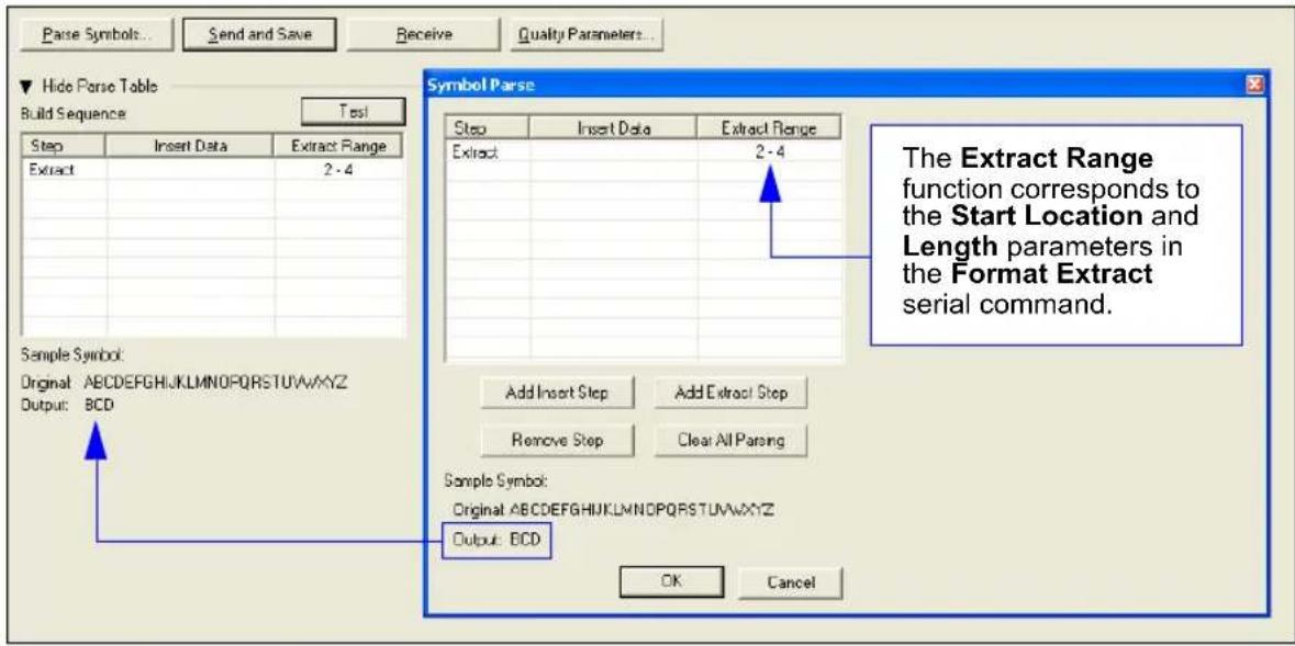
text_image
Parse Symbols... Send and Save Receive Quality Parameters... Hide Parse Table Build Sequence Test Step Insert Data Extract Range Extract 2 - 4 Sample Symbol: Original: ABCDEFGHIJKLMNOPQRSTUVWXYZ Output: BCD Symbol Parse Step Insert Data Extract Range Extract 2 - 4 Add Insert Step Add Extract Step Remove Step Clear All Parsing Sample Symbol: Original: ABCDEFGHIJKLMNOPQRSTUVWXYZ Output: BCD OK Cancel The Extract Range function corresponds to the Start Location and Length parameters in the Format Extract serial command.You can extract and insert several character sequences using ESP's Symbol Parse feature. In this example, the selected extraction range is characters 2-4. The "Sample Symbol" example on the Symbol Parse dialog shows the selected character positions extracted and output as desired. Simultaneously, the data string from the actual selected symbol is displayed at the bottom left of the Parse Table, followed by the user-defined extracted output.
Format Insert
Output Index
Definition:
Output Index refers to the database entry you wish to modify with this command. A formatted output is built by extracting data from a symbol's original data output and/or inserting user-defined characters.
It may be helpful to think of individual indexes as positions in the final formatted output you wish to build. Starting with index # 1, enter either an extract or insert command to begin building your desired output string. Then, with the next index number, enter either an extract or insert command to continue building the output string. Continue this process until you are finished building the string.
Serial Cmd:
Options: 1 to 100
Length
Definition:
Specifies the length of the user-defined character string that will be inserted. This function is limited to 4 characters per output index, so multiple indexes must be entered in order to insert longer character sequences.
For example, if you wish to insert a 10 character sequence in user-defined output, you would need three commands with consecutive index numbers, where the first two character sequence lengths were 4 and the third was 2.
Serial Cmd:
Default: 0 (disabled; end of format cell array)
Options: 1 to 4
Hex String
Definition:
Specifies a character string that represents ASCII characters to be inserted in the database entry. Two hex characters are required for every ASCII character to be inserted in the user-defined output string. These two characters comprise the hex (base 16) value of the ASCII character.
For example, if you wanted to enter the three-character sequence "Hi!" you would enter 3 for the length of the string, and a hex sequence of 486921 for the ASCII sequence to be inserted. (48 = H; 69 = i; 21 = !)
Important: Each pair of hex characters represents one ASCII character. Hex character pairs range from 00 to FF. Since you are limited to 4 ASCII characters per insertion per database entry, you are likewise limited to 8 hex characters per insertion per database entry.
Serial Cmd:
Default: NUL (00 in hex)
Options: 00 to FF (As many as 4 bytes, or hex pairs.)
Format Insert
Format Insert by ESP
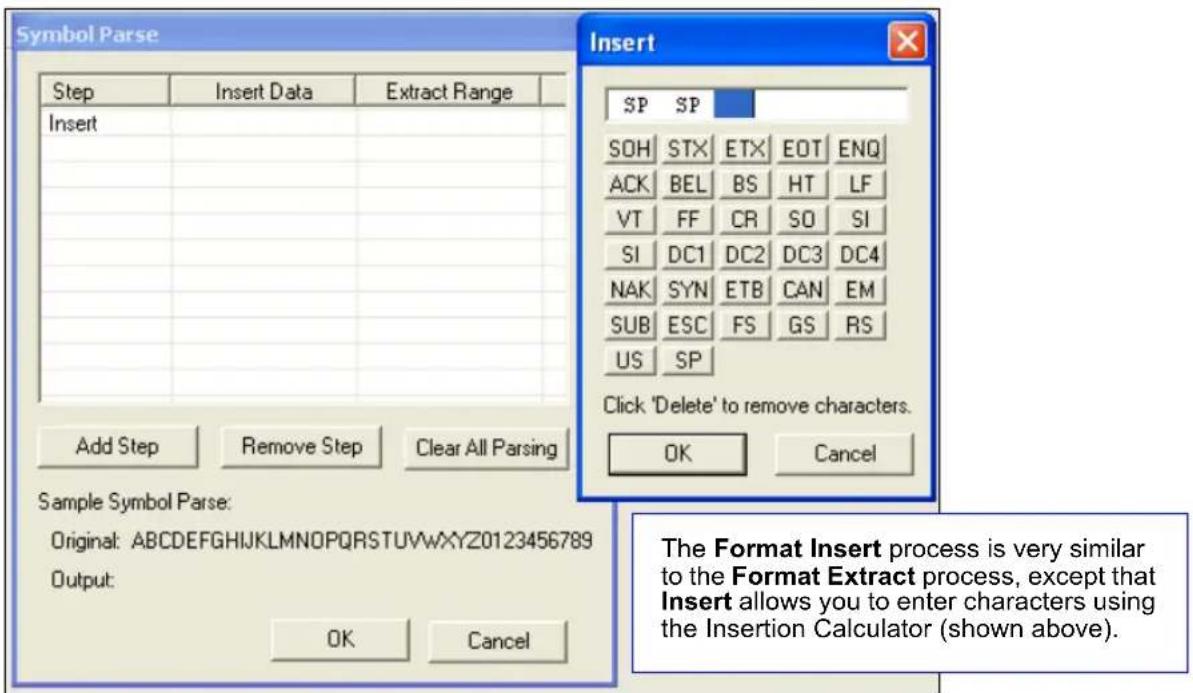
text_image
Symbol Parse Step Insert Data Extract Range Insert Add Step Remove Step Clear All Parsing Sample Symbol Parse: Original: ABCDEFGHIJKLMNOPQRSTUVWXYZ0123456789 Output: OK Cancel Insert SP SP SOH STX ETX EOT ENQ ACK BEL BS HT LF VT FF CR SO SI SI DC1 DC2 DC3 DC4 NAK SYN ETB CAN EM SUB ESC FS GS RS US SP Click 'Delete' to remove characters. OK Cancel The Format Insert process is very similar to the Format Extract process, except that Insert allows you to enter characters using the Insertion Calculator (shown above).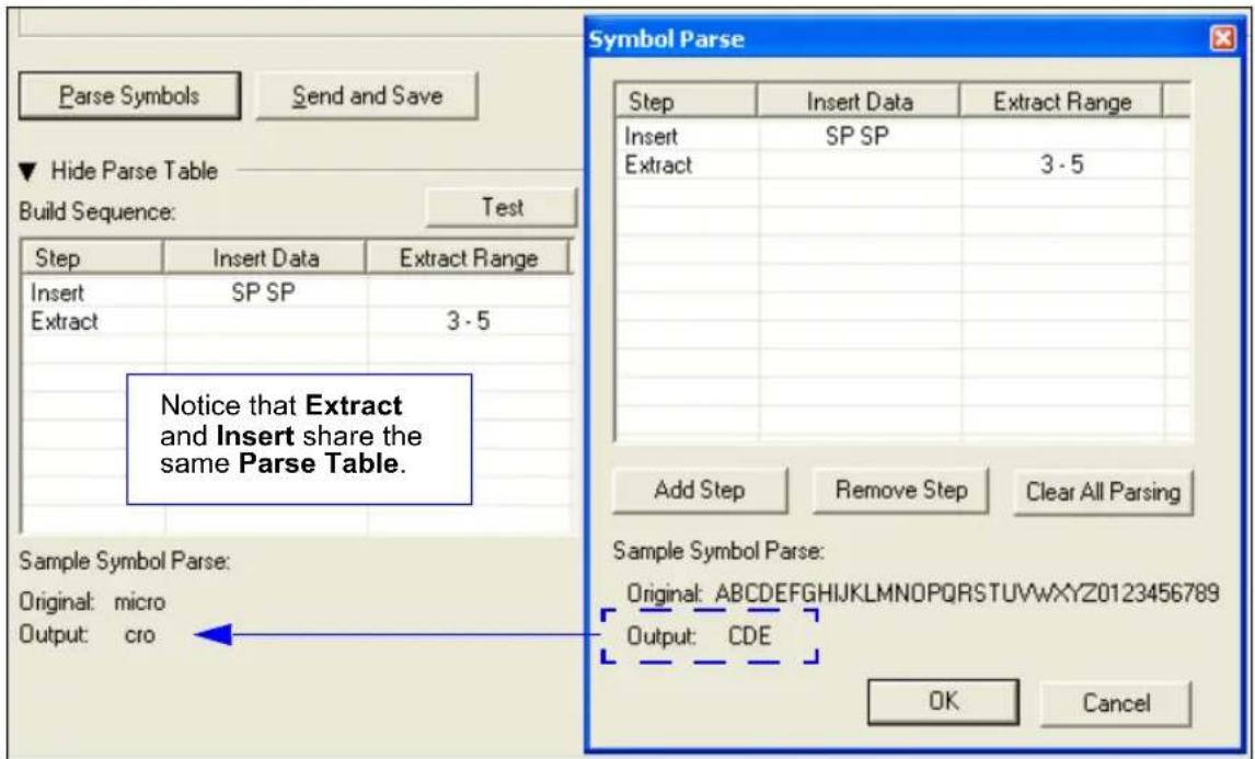
text_image
Parse Symbols Send and Save Hide Parse Table Build Sequence: Test Step Insert Data Extract Range Insert SP SP Extract 3 - 5 Notice that Extract and Insert share the same Parse Table. Sample Symbol Parse: Original: micro Output: cro Symbol Parse Step Insert Data Extract Range Insert SP SP Extract 3 - 5 Add Step Remove Step Clear All Parsing Sample Symbol Parse: Original: ABCDEFGHIJKLMNOPQRSTUVWXYZ20123456789 Output: CDE OK CancelOutput Filter Configuration
Definition:
Output filtering is a method of providing a set of good read qualifiers and also providing ordered output. There is a filter for up to the first 10 positions in a multisymbol output. The first filter corresponds to the first symbol output at the end of the read cycle. Each filter has has settings for the following four parameters: Symbology Type, Symbol Length, Data, and Configuration Database Number.
Serial Cmd:
Rules for Output Filter Configuration
Output Filter Configuration Rule # 1
Each symbol that is decoded must match one of the filters before it can be saved to a read cycle record. There is an exception to this rule, however, when the number of symbols required for a read cycle exceeds the number of active filters. In such a case, unfiltered symbols can be placed into unfiltered output positions.
For example, if the number of symbols required is 6 but there are only 4 active filters, the last 2 positions can be filled by any (unfiltered) qualified symbol.
Output Filter Configuration Rule # 2
The same filter setup can be used multiple times.
For example, filters 1, 2, and 3 can be set up to filter Data Matrix symbols, and the output will occur in the order the symbols are decoded.
Output Filter Configuration Rule # 3
All qualified symbols will be sorted and output in the matching filter position. If a symbol matches filter 3, it will be output as the third symbol. If a filter does not have a matching qualified symbol, a No Read message will be output in place of the symbol (assuming the No Read message is enabled).
For example, if there is not a symbol that meets filter 3's requirements, then a No Read message will be output in the third output position.
Output Filter Configuration
Filter Number
Definition: This is the filter index number that represents the position of the symbol in the data output at the end of the read cycle. This index number should be entered along with the following filter settings for the predetermined symbol position.
Serial Cmd:
Options: 1 to 12
Symbology
Definition: Specifies the symbology type allowed to occupy this location in multisymbol output. Note: To filter or order a symbol, the symbol must meet all the requirements of the selected filter index.
Serial Cmd:
Default: 0 (any symbology type)
Options: 0 = Any type 1 = Interleaved 2 of 5 2 = Code 39 3 = Code 128 4 = Codabar 5 = UPC 6 = PDF417 7 = EAN 128 8 = Code 93 9 = Pharmacode
Length
Definition: Specifies the length of the decoded symbol allowed to occupy this location in multisymbol output.
Note: To filter or order a symbol, the symbol must meet all requirements of the selected filter index.
Serial Cmd:
Default: 0
Options: 0 to 128
Wildcard
Definition: This is the character to be used in the data output field when performing a data filter comparison. The wildcard character represents the end of matching, and allows for variable lengths of symbol output.
Serial Cmd:
Default: “ * ” = (2A in hex)
Options: Any ASCII input in the form of a pair of hex characters.
Example:
2A = *
00 = disabled
Placeholder
Definition: The placeholder character requires a character to be present, but does not compare the data value.
Serial Cmd:
Default: “?” = (3F in hex)
Options: Any ASCII input in the form of a pair of hex characters.
Example:
3F = ?
00 = disabled
Data
Definition: This is the data string to be used when comparing symbol data for output filtering and ordering. This data string may also contain wildcard and placeholder characters to facilitate matching. Remember that in order to filter or order symbol data, it must meet all the requirements of the selected filter index.
- Filter data = "123*". This will match data strings of "123", "123456", and "123ABC", but not "12".
- Filter data = "123*AB?C". This will be interpreted as "123*".
- Filter data = "123?". This will match "1234" and "123A", but not "123", "12345", or "1234C".
- Filter data = "123?A". This will match "1234A" and "123BA", but not "123", "1234C", or "1234ABCD".
- Filter data = "123?A?". This will match "1234AB" and "123BAT", but not "1234A" or "123BATS".
- Filter data = "12??*". This will match "1234", "123456", and "123ABC", but not "12" or "123".
- Filter data = "123?A*". This will match "1234A", "123BA", and "123BATS", but not "1234" or "1234C".
Examples:
Serial Cmd:
Default: NUL (00 in hex)
Options: Any ASCII input in the form of a pair of hex characters.
Maximum length: 63 bytes defined.
Examples:
$$ 4 1 4 2 2 \mathrm{A} = \mathrm{AB} ^ {*} $$
Data [0] = NUL represents string matching disabled.
Decode Direction
Definition: Decode direction is determined by the direction of the output filter.
Serial Cmd:
Default: 0 (any direction)
Options: 0 = Any Direction
1 = Forward
2 = Reverse
Database Index
Definition: The index of the database entry that decodes a given symbol must equal this setting for filtering to occur. A setting of 0 allows any database index for this filter entry.
Serial Cmd:
Default: 0
Options: 0 = Any Database Index
1 = Database # 1 to n (maximum number of characters in the symbol data)
Number of Filters
Number of Filters
Definition: Number of Filters refers to the number of active output filters. 0 disables all output filters. Any non-zero numeral will enable filtering to be performed using the filter indexes covered by this value. For example, if the number of filters is 1, then only filter index # 1 will be applied. If the number of filters is 2, then only filter index # 1 and filter index # 2 will be applied, etc.
Serial Cmd:
Default: 0
Options: 0 to 12
Wiring Box
Contents
Wiring Box Description 14-2
Installation Steps 14-3
Wiring Box Ports.... 14-5
Wiring Box PCB with Connectors 14-8
Mounting Plate.... 14-9
This section has instructions for assembling, wiring and using the MS-890's optional Wiring Box. When this option is selected, the MS-890 and wiring box option are shipped as an assembly.
Wiring Box Description
Wiring Box Description
Note: The wiring box PCB resides inside the wiring box.
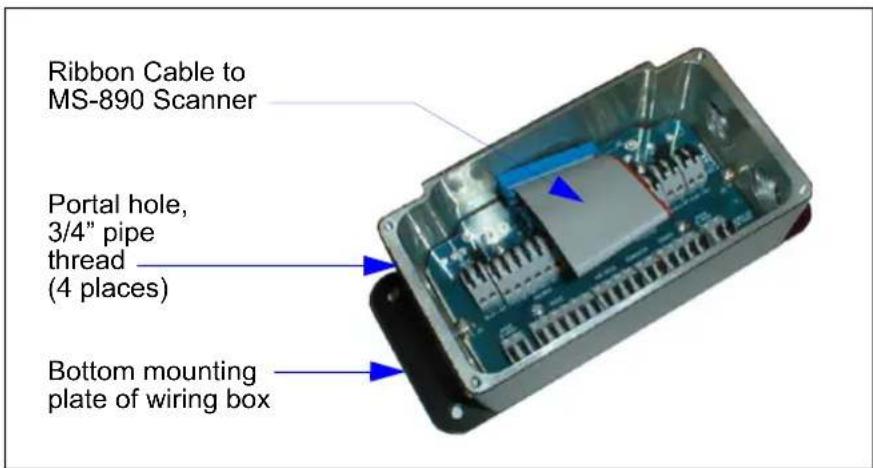
text_image
Ribbon Cable to MS-890 Scanner Portal hole, 3/4" pipe thread (4 places) Bottom mounting plate of wiring boxPortal Holes
The wiring box has four external portal holes which are standard 3/4" pipe thread. Mounting of the box is with four through holes in flanges that extend out over the ends.
Terminal Strip Specifications
Wire strip length: .24" (6 mm)
Wiring range: 14 - 28 AWG
Current: 13A maximum
Installation Steps
- Connect power through the portal holes (see Check Required Hardware on page 1-2).
- Temporarily apply power to the scanner and confirm that the light next to the input terminal is green and not red.
- Disconnect power before making the remaining connections.
- Connect the host and trigger port wires through the portal holes to the appropriate connections.
- Plug the ribbon cable into the scanner as shown below (apply pressure back and forth on the connector to ensure that it fits inside the receptacle).
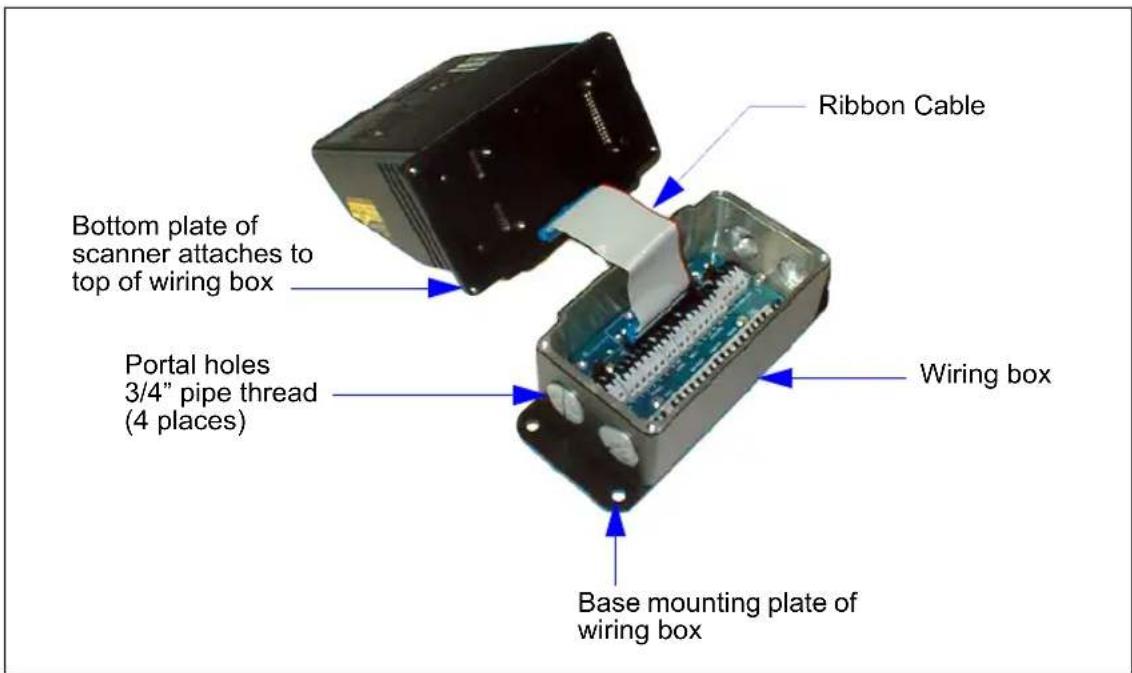
text_image
Bottom plate of scanner attaches to top of wiring box Portal holes 3/4" pipe thread (4 places) Ribbon Cable Wiring box Base mounting plate of wiring boxInstallation Steps (cont.)
Installation Steps (cont.)
- Attach the scanner to the wiring box with four attached mounting screws in the bottom plate of the scanner, making sure that the gasket is evenly seated.
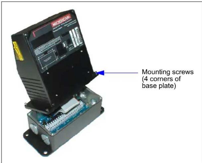
text_image
MICROSCAN Mounting screws (4 corners of base plate)- Mount the wiring box (see Wiring Box Ports on page 14-5).
Wiring Box Ports
Relay Modules
These can be used as an alternative to the 3 optoisolated outputs from the scanner itself. K1, K2, and K3 are module sockets for SM off-the-shelf AC/DC output/relay modules.
Note: For relay module kits, use a slim module that does not exceed 0.43" (11 mm) in width.
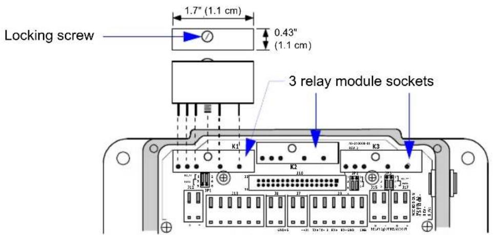
text_image
Locking screw 1.7" (1.1 cm) 0.43" (1.1 cm) 3 relay module sockets K1 K2 K3Jumpers
When installing relay modules in K1, K2, and K3, corresponding jumpers (J1, J2, J3) need to be moved. Move jumpers from 3-5 to 1-3 and 4-6 to 2-4 for each relay to be installed (K1, K2, K3).
Default jumper positions (using scanner's built-in relay)
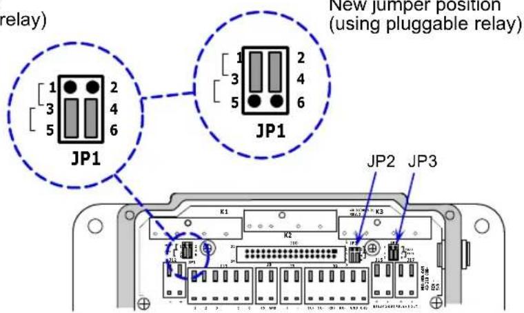
text_image
relay) JP1 New jumper position (using pluggable relay) JP1 JP2 JP3 K1 K2 K3Wiring Box Ports
Relay Terminals
Relay terminals 1, 2, and 3 provide output for both internal optoisolated outputs and alternative relay modules that can be installed in modules K1, K2, and K3.
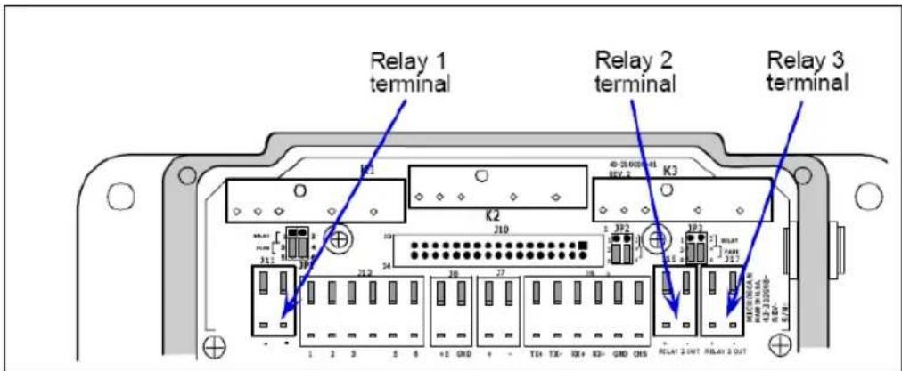
text_image
Relay 1 terminal Relay 2 terminal Relay 3 terminal K1 K2 K3 1 2 3 4 5 6 +E GND + - T0+ TX- RX+ K3- GND CNS RELAY 2 OUT RELAY 2 OUT 10 210 1 2F2 1F2 1F5 1F5 1F5 1F5 1F5 1F5 1F5 1F5 1F5 1F5 1F5 1F5 1F5 1F5 1F5 1F5 1F5 1F5 1F5 1F5 1F5 1F5 1F5 1F5 1F5 1F6 1F6 1F6 1F6 1F6 1F6 1F6 1F6 1F6 1F6 1F6 1F6 1F6 1F6 1F6 1F6 1F6 1F6 1F6 1F6 1F6 1F6 1F6Relay1 Output handles discrete outputs from the scanner that will switch up to 100 mA of optoisolated current.
+5 VDC
Voltage out that can drive a hand held scanner. Maximum current is 5 watts.
Input 1
Used to wire a switch to reset latch mode or counters.
RS-422/485
Used for multidrop or 422 port.
Power 10-28 VDC
Power input port (left side and right side for connectivity convenience).
RS-232
Main serial communication port.
Aux RS-232
Daisy chain and Auxiliary connections.
New Master Pin
Allows you to wire in a switch for New Master Pin. (See Optoisolator Inputs on page A-7.)
Trigger Port (NPN)
To initiate the read cycle. (See Optoisolator Inputs on page A-7.)
Power LED
GREEN means the polarity of the input connections is correct; RED means it is reversed.
Caution: While the MS-890 scanner has reverse polarity protection built in to its circuitry, the wiring box does not protect external circuits that may already be wired in when power is applied.
Wiring Box PCB with Connectors
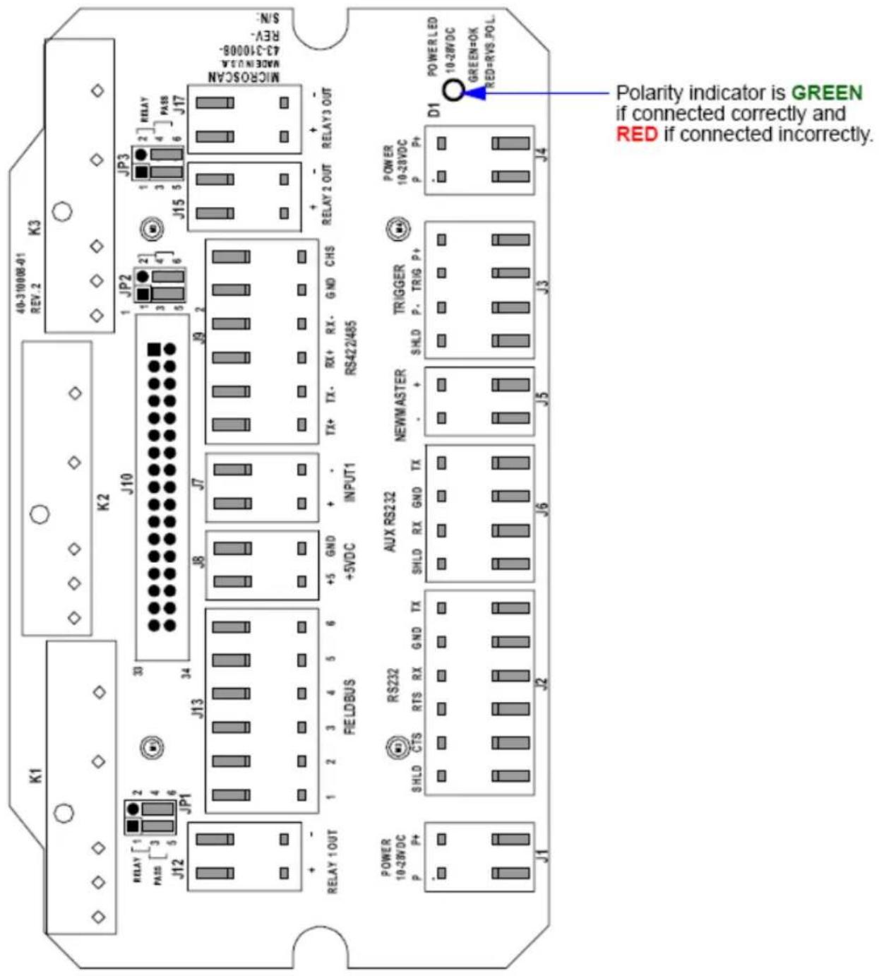
text_image
K1 K2 J10 JP3 JP2 1 2 3 4 5 6 J9 2 J7 J8 J7 +5 GND INPUT1 + RX+ RX- GND CHS RS422/465 J13 J12 JP1 RELAY [1] 2 3 4 5 6 PASS [3] 4 5 6 J10 RELAY 1 OUT RELAY 2 OUT RELAY 3 OUT POWER LED 10-28VDC GREEN=OK RED=RVS POL. POWER 10-28VDC P P+ J4 J3 J5 J6 J2 J1 POWER 10-28VDC P P+ J1 J2 J3 J4 J5 J6 J7 J8 J9 J10 40-3100/08-01 REV:2 K3 S/N- REV- MOSIENOLA 43-3100/08- MicroSCAN S/N- 1 JP2 2 3 4 5 6 1 2 3 4 5 6 +5 GND INPUT1 + RX+ RX- GND CHS + RX+ RX- GND CHS + RX+ RX- GND CHS + RX+ RX- GND CHS + RX+ RX- GND CHS + RX+ RX- GND CHS + RX+ RX- GND CHS + RX+ RX- GND CHS + RX+ RX- GND CHS + RX+ RX- GND CHS + RX+ RX- GND CHs + RX+ RX- GND CHs + RX+ RX- GND CHs + RX+ RX- GND CHs + RX+ RX- GND CHs + RX+ RX- GND CHs + RX+ RX- GND CHs + RX+ RX- GND CHs + RX+ RX- GND CHs + RX+ RX- GND CHs + RX+ RX- GND CHS + RX+ RX- GND CHS + RX+ RX- GND CHS + RX+ RX- GND CHS + RX+ RX- GND CHS + RX+ RX- GND CHS + RX+ RX- GND CHS + RX+ RX- GND CHS + RX+ RX- GND CHS + RX+ RX- GND CHN + RX+ RX- GND CHN + RX+ RX- GND CHN + RX+ RX- GND CHN + RX+ RX- GND CHN + RX+ RX- GND CHN + RX+ RX- GND CHN + RX+ RX- GND CHN + RX+ RX- GND CHN + RX+ RX- GND CHN + RX+ RX- GND CHn + RX+ RX- GND CHn + RX+ RX- GND CHn + RX+ RX- GND CHn + RX+ RX- GND CHn + RX+ RX- GND CHn + RX+ RX- GND CHn + RX+ RX- GND CHn + RX+ RX- GND CHn + RX+ RX- GND CHn + RX+ RX- GND CHm + RX+ RX- GND CHm + RX+ RX- GND CHm + RX+ RX- GND CHm + RX+ RX- GND CHm + RX+ RX- GND CHm + RX+ RX- GND CHm + RX+ RX- GND CHm + RX+ RX- GND CHm + RX+ RX- GND CHm + RX+ RX- GND CHn + RX+ RX- GND CHn + RX+ RX- GND CHn + RX+ RX- GND CHn + RX+ RX- GND CHn + RX+ RX- GND CHn + RX+ RX- GND CHn + RX+ RX- GND CHn + RX+ RX- GND CHn + RX+ RX- GND CHc + RX+ RX- GND CHc + RX+ RX- GND CHc + RX+ RX- GND CHc + RX+ RX- GND CHc + RX+ RX- GND CHc + RX+ RX- GND CHc + RX+ RX- GND CHc + RX+ RX- GND CHc + RX+ RX- GND CHc + RX+ RX- GND CHh + RX+ RX- GND CHh + RX+ RX- GND CHh + RX+ RX- GND CHh + RX+ RX- GND CHh + RX+ RX- GND CHh + POWER 10-28VDC P P+ J1 J2 J3 J4Mounting Plate
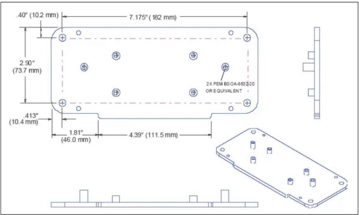
text_image
.40" (10.2 mm) 7.175" (182 mm) 2.90" (73.7 mm) .413" (10.4 mm) 1.81" (46.0 mm) 4.39" (111.5 mm) 2X PEM BSOA-8632-20 OR EQUIVALENTIB-890 Wiring Box Mounting Plate
Mounting Plate
Appendices
Appendix A General Specifications....A-2
Appendix B Electrical Specifications.... A-4
Appendix C Serial Configuration Commands A-9
Appendix D ASCII Table A-15
Appendix E Embedded Menus ...... A-17
Appendix F Defaulting / Saving / Initializing...... A-18
Appendix G Position Scanner and Symbol ...... A-21
Appendix H Object Detector A-22
Appendix I Bar Code Configuration ...... A-23
Appendix J Test Read Rate....A-25
Appendix K Formulas for Number of Decodes ...... A-27
Appendix L Operational Tips.... A-32
Appendix M Interface Standards.... A-33
Appendix N Multidrop Communications....A-34
Appendix O Glossary of Terms...... A-39
General Specifications
Appendix A — General Specifications
Mechanical
Height: 3.5" (88 mm)
Width: 5" (127 mm)
Depth: 6" (152 mm)
Weight: 5 lbs. (2268 g)
Environmental
Enclosure: IP65
Operating Tempurature: 0° to 50°C (32° to 122°F)
Storage Tempurature: -50° to 75° C (-58 to 167°F)
Humidity: up to 90% (non-condensing)
Emissions and Immunity
EN61000-6-3:2001: for Class A products
EN61000-3-2:2000+A2:2005
EN61000-3-3:1995+A1:2001
EN61000-6-2: Immunity
Laser Light
Type: Semiconductor visible laser diode (650 nm nominal)
Operating Life: 50,000 hours @ 25°C (77°F)
Safety Class: CDRH Class II
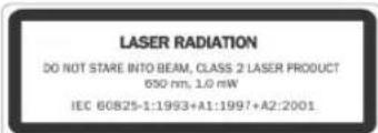
text_image
LASER RADIATION DO NOT STARE INTO BEAM, CLASS 2 LASER PRODUCT 650 nm, 1.0 mW IEC 60825-1:1993+A1:1997+A2:2001Indicators
Beeper: Good Read, Match/Mismatch, No Read, serial command confirmation
LEDS: 1 status, 1 power, 1 Good Read, 5 read performance (representing percentage of good decodes), network/include status, green flash
Discrete I/O
Trigger, New Master, Input 1: Optoisolated, 5-28V rated (12mA at 24VDC)
Outputs (1, 2, 3): Optoisolated, 1-28VDC rated, (I_CE < 100mA @ 24VDC, current limited by user)
Communications
Interface: RS-232, RS-422485, Daisy Chain/Aux Port-capable, dedicated configuration port
Symbologies
Standard symbologies: Code 39, Code 128, UPC/EAN, Interleaved 2 of 5, Codabar, Code 93, PDF417
Applications Standards: AIAG, GS1-128
Scanning Parameters
Scanner Mirror Type: Rotating, single line, 14-faceted
Scan Rate: Adjustable from 400 to 1000 scans/second (default = 500 scans/second)
Raster Sweep Speed: 1 to 30 sweeps/second
Raster Sweep Angle: 30° maximum
Scan Width Angle: Typically 60°
Pitch Angle: ±50° maximum
Skew Angle: ±40° maximum
Contrast: 25% min. absolute dark-to-light differential at 650 nm wavelength
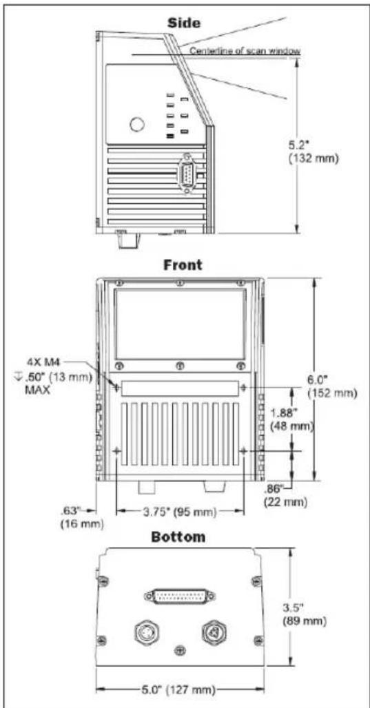
text_image
Side Centrétine of scan window 5.2" (132 mm) Front 4X M4 .50" (13 mm) MAX 6.0" (152 mm) 1.88" (48 mm) 86" (22 mm) .63" (16 mm) 3.75" (95 mm) Bottom 3.5" (89 mm) 5.0" (127 mm)MS-890 Dimensions
Read Ranges
| Symbol/Narrow Bar Width Read Range | |
| 7.5 mil (.190 mm) 10" to 35" (254 to 889 mm) | |
| 10 mil (.254 mm) 10" to 44" (254 to 1118 mm) | |
| 15 mil (.381 mm) 10" to 74" (254 to 1880 mm) | |
| 20 mil (.508 mm) 10" to 90" (254 to 2286 mm) | |
| 30 mil (.762 mm) 10" to 100" (254 to 2540 mm) | |
| 40 mil (1.020 mm) 10" to 110" (254 to 2794 mm) | |
| 50 mil (1.27 mm) 10" to 120" (254 to 3048 mm) |
FIS Options
| MS-890 Industrial Automation Scanner | |
| Long Range, Stand Alone Version, RS-232/485, 10-28VDC FIS-0890-0001G | |
| Long Range, Wiring Box-Ready, RS-232/485, 10-28VDC FIS-0890-0002G |
Safety Certifications
FCC, CDRH, CE, UL/cUL, BSMI, RoHS/WEEE Compliance



©2015 Microscan Systems, Inc.
All rights reserved. Specifications subject to change.
Product specifications are given for typical performance at 25^ C ( 77^ F) using grade A labels. Performance characteristics may vary at high temperatures or other environmental extremes. Warranty—One year limited warranty on parts and labor. Extended warranty available.
Appendix B — Electrical Specifications
Maximum Operating Power: 24 Watts
Power Requirement: 10 to 28VDC, 200mV p-p max. ripple, 230mA @ 24VDC (typ.)
Trigger, New Master, Input 1: 4.5 to 28 VDC (optoisolated)
Connectors at the base of the MS-890 unit::
- Power Connector
- Host 25-Pin Connector
- Trigger Connector
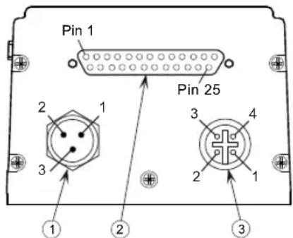
text_image
Pin 1 Pin 25 2 1 3 3 4 2 1 ① ② ③Caution: Be sure that all cables are connected BEFORE applying power to the system. Always power down BEFORE disconnecting any cables.
Power Connector: 3-pin microchange plug
| 1 Power Ground | |
| 2 | N/C |
| 3 Power 10 to 28 VDC (in) | |
Caution: If using your own power supply, verify correct connection of power and ground lines. Incorrect connections or use of “Chassis ground,” “Power ground,” and “Signal ground” lines could cause equipment and/or software failure.
Trigger Connector: 4-pin microchange socket
| 1 | Power 10 to 28 VDC (out) |
| 2 | NPN |
| 3 | Ground |
| 4 | N/C |
Programming Connector: 9-pin D-sub plug
| 2 RX232 |
| 3 TX232 |
| 5 Signal Ground |
| 9 Boot Mode |
Note: RS-422 and RS-232 are both enabled by default in the MS-890.
Host 25-Pin Connector
25-pin D-sub plug
| Pin | Host RS-232 | Host and Aux RS-232 Host RS-422/485 I/O | ||
| 1 Chassis Ground a | ||||
| 2 Host TxD Out | ||||
| 3 Host RxD In | ||||
| 4 RTS Aux TxD Out | ||||
| 5 CTS Aux RxD In | ||||
| 6 Output 1 (+) Out | ||||
| 7 Signal Ground b | ||||
| 8 Output 2 (+) Out | ||||
| 9 | Trigger (−) | In | ||
| 10 | Trigger (+) | In | ||
| 11 | N/C | |||
| 12 | Input 1 (+) | In | ||
| 13 | RxD (+) | In | ||
| 14 | TxD (−) | Out | ||
| 15 | No Read/Output 3 (+) | Out | ||
| 16 | RxD (−) | In | ||
| 17 | Power Ground c | |||
| 18 | Power + 10 to 28 VDC | In | ||
| 19 | TxD (+) | Out | ||
| 20 | Output 1 (−) Out | |||
| 21 | Output 2 (−) Out | |||
| 22 | No Read/Output 3 (−) | Out | ||
| 23 | Input 1 (−) In | |||
| 24 | New Master (−) | In | ||
| 25 | New Master (+) | In | ||
a. Chassis Ground: Used to connect chassis body to earth ground only. Not to be used as power or signal return.
b. Signal Ground: Used for communication and signal line grounds only. Not to be used as power or chassis return.
c. Power Ground: Used for power return only.
CAUTION: If using your own power supply, verify correct connection of power and ground lines. Incorrect connections or use of Chassis Ground, Power Ground, and Signal Ground lines could cause equipment failure or software failure.
Electrical Specifications
Optoisolator Outputs
Optoisolator circuits can transfer pulses between the scanner and peripherals with no direct connection with the scanner's internal circuitry. However, not every optoisolator configuration provides complete isolation. The following diagrams show both fully optisolated and non-optoisolated circuits. They are only examples and do not represent all possible wiring configurations.
| I_load =5mA I | _load =50mA I | _load =100mA | |
| V_Out-On | 0.7V 0.9V | 1.0V | |
| t_On-Typ | 30 μS 20 μS | 30 μS | |
| t_Off-Typ | 1000 μS 150 | μS 75 μS |
Output Circuit Examples
Fully Optoisolated
This circuit is fully optoisolated and is the recommended configuration. It allows the user to apply 1 to 28VDC to the circuit.
Caution: The maximum current that can pass through the optoisolator is 100mA.
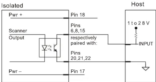
flowchart
graph TD
    A["Isolated"] --> B["Pwr +"]
    B --> C["Scanner Output"]
    C --> D["Resistor"]
    D --> E["Pins 6,8,15"]
    E --> F["respectively paired with: Pins 20,21,22"]
    F --> G["Pin 17"]
    G --> H["Host"]
    H --> I["1 to 2.8 V INPUT"]
Not Optoisolated, Scanner Grounded
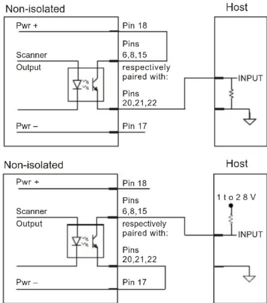
text_image
Non-isolated Pwr + Scanner Output Pwr - Pin 18 Pins 6,8,15 respectively paired with: Pins 20,21,22 Pin 17 Host INPUT Non-isolated Pwr + Scanner Output Pwr - Pin 18 Pins 6,8,15 respectively paired with: Pins 20,21,22 Pin 17 Host 1 to 2.8 V INPUTOptoisolator Inputs
New Master pin and Trigger pulses can be sent to the scanner in the following ways:
New Master Pin Inputs
| Waveform Characteristics: | ||
| Minimum | Maximum | |
| V_IN-HIGH / I_IN-HIGH | 4.5V / 4 mA | 2 |
| V_IN-LOW / I_IN-LOW | 0V / 0 mA | 2V / 2 mA |
| Pulse Width_min | 48 μS | |
25-pin Host Connector
The following New Master Pin inputs can be fully isolated pulses as PNP or NPN circuits.
PNP Circuits
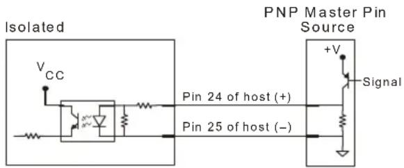
text_image
Isolated VCC Pin 24 of host (+) Pin 25 of host (–) PNP Master Pin Source +V SignalNPN Circuits
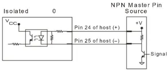
text_image
Isolated 0 VCC Pin 24 of host (+) Pin 25 of host (–) NPN Master Pin Source +V SignalElectrical Specifications
Trigger Inputs
| Waveform Characteristics: | ||
| Minimum Maximum | ||
| VIN-HIGH / IIN-HIGH | 4 | 5 |
| VIN-LOW / IIN-LOW | 0 V / 0 mA | 2V/2 mA |
| Pulse Width min | 48 μS | |
Trigger pulses can be sent to the scanner either through the host 25-pin connector or a separate 4-pin trigger connector on the bottom of the scanner.
4-pin Trigger Input
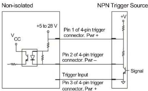
text_image
Non-isolated NPN Trigger Source +5 to 28 V Pin 1 of 4-pin trigger connector. Pwr + Pin 2 of 4-pin trigger connector. Pwr - Trigger Input Pin 3 of 4-pin trigger connector. Pwr + +V Signal25-pin Trigger Input
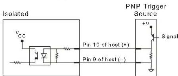
text_image
Isolated VCC Pin 10 of host (+) Pin 9 of host (−) PNP Trigger Source +V Signal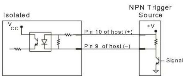
text_image
Isolated Vcc Pin 10 of host (+) Pin 9 of host (–) NPN Trigger Source +V Signal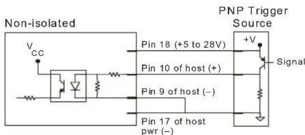
text_image
Non-isolated VCC Pin 18 (+5 to 28V) Pin 10 of host (+) Pin 9 of host (–) Pin 17 of host pwr (–) PNP Trigger Source +V Signal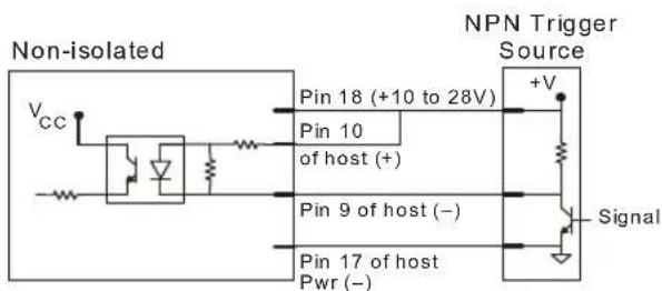
text_image
Non-isolated Vcc Pin 18 (+10 to 28V) Pin 10 of host (+) Pin 9 of host (−) Pin 17 of host Pwr (−) NPN Trigger Source +V SignalAppendix C — Serial Configuration Commands
Communications
| Host Port Parameters | |
| Aux Port Parameters | |
| Host Protocol | |
| Preamble | |
| Postamble | |
| Response Timeout | |
| Intercharacter Delay | |
| LRC | |
| Auxiliary/Configuration Port System Data | |
| ACK/NAK Options | |
| Polling Mode Options | |
| Daisy Chain Autoconfigure | |
| Daisy Chain Scanner ID |
Read Cycle
| Trigger Mode | |
| Serial Trigger Character | |
| External Trigger State | |
| End of Read Cycle | |
| Good Decode Reads | |
| Multisymbol | |
| Start Serial Trigger Character | |
| End Serial Trigger Character | |
| Scan Speed | |
| Maximum Element | |
| Gain/Tracking | |
| AGC Settings | |
| Focus | |
| Tracking Adjustment |
Symbologies
| Narrow Margins/Symbology ID | |
| Background Color | |
| Code 39 | |
| Codabar | |
| Interleaved 2 of 5 |
Serial Configuration Commands
| UPC/EAN | |
| Code 128/EAN-128 | |
| Code 93 | |
| PDF417 | |
| Pharmacode |
| I/O Parameters | |
| Serial Verification | |
| Beeper | |
| Quality Output | |
| Symbol Data Output | |
| Read Duration Output | |
| No Read Message | |
| Bad Symbol Message | |
| No Symbol Message | |
| Input 1 | |
| Target/Flood LEDs | |
| Database Identifier Output | |
| EZ Button | |
| EZ Button Modes | |
| Trend Analysis Output 1 | |
| Trend Analysis Output 2 | |
| Trend Analysis Output 3 | |
| Diagnostic Output 1 | |
| Diagnostic Output 2 | |
| Diagnostic Output 3 | |
| Configurable Output 1 | |
| Configurable Output 2 | |
| Configurable Output 3 | |
Matchcode
| Matchcode Type |
Appendices
| Master Symbol Database Size | |
| New Master Pin | |
| Configuration Database | |
| Sequential Step | |
| Enter/Delete Master Symbol Data | |
| Request Master Symbol Data | [for all] or |
| Match Replacement Message | |
| Mismatch Replacement Message |
| Diagnostics | |
| Warning Message Status | |
| Lifetime Hours | |
| High Temperature | |
| Low Temperature | |
| Power-On/Resets Counts | returns: power-ons, resets (Read-Only) |
| Hours Since Last Reset | returns: hours,minutes (Read-Only) |
| Present Operating Temperature | returns: current operating temp. (Read-Only) |
| Service Message | |
| Laser Current Warning | |
| Calibration / Configuration Database | |
| Optoelectric Control | |
| Configuration Database | |
| Save Configuration Database | |
| Load Configuration Database | |
| Request Configuration Database | orfor entire database. |
| Advanced Calibration | |
| Raster/Laser | |
| Raster | |
| Laser On/Off | |
| Output Format | |
| Format Extract | |
Serial Configuration Commands
| Format Insert | |
| Format Assign | |
| Format Status | |
| Output Filter Configuration | |
| Number of Filters |
Serial Command Format
Serial commands are of two types: utility and configuration.
Rules that apply to both utility and configuration commands
- A less than < and greater than > character enclose the commands.
- Commands and data are “case sensitive.” That is, characters must be entered as upper or lower case, as specified.
Serial Utility Commands
These are sent during operations and are not followed by or
Serial Configuration "K" Commands
These begin with a single K character followed by a 3-digit numeric character, data fields, and an initializing command, as follows:
An initializing command or
For example, to enable UPC and save the change for power-on, send
To change Baud Rate and reset without saving changes for power-on, send
Serial Configuration Command Conventions
- All data fields (except the last) must be followed by a comma (without a space).
- All fields preceding a modified field must be included.
- If there is no change in preceding fields, then commas alone can be entered in these fields. For example, if only the last field in the following command is changing,
- All fields following a modified field can be omitted. For example, to change Baud Rate only, send
Concatenating Configuration Commands
Commands can be concatenated (added together) in a single string or data block. For example,
Serial Command Status Request
To ensure that any command was received and accepted, you can send the Show Reader Status command: <?>.
The status of a specific serial command can be requested by entering the command followed by a question mark. For example, send
Entering Control Characters in Serial Commands
To enter control characters within a serial command, hold down the Ctrl key while typing the desired character.
Example: To enter a carriage return and line feed ( ^M J), enter
Entering Special Characters in Embedded Menus
Control Characters
Control characters entered on the command line are displayed in the menu as mnemonic characters, such as:
Press SP (the space bar) once, then enter the control character by holding down the control key and simultaneously pressing the desired character. For example to define a line feed, press SP, then Control and J simultaneously. It is displayed as ^J on the command line and as
To Define a Carriage Return as a Character
Press SP, then CR. It is displayed as ^M on the command line and as
To Define a Space as a Character
Press SP twice. It is displayed as a blank space in the menu when the screen is refreshed. While it appears that nothing has been assigned, the hex value 20 will be sent during data transmission.
To Select NUL as the Character
Press SP, then a 0. It is displayed as
Appendix D — ASCII Table
ASCII Table with Control Characters
| Dec Hex Mne Ctrl Dec Hex Ch | Dec Hex Ch Dec Hex Ch | |||||||||||
| 00 | 00 | NUL | ^@ | 32 | 20 | SP | 64 | 40 | @ | 96 | 60 | ` |
| 01 | 01 | SOH | ^A | 33 | 21 | ! | 65 | 41 | A | 97 | 61 | a |
| 02 | 02 | STX | ^B | 34 | 22 | “ | 66 | 42 | B | 98 | 62 | b |
| 03 | 03 | ETX | ^C | 35 | 23 | # | 67 | 43 | C | 99 | 63 | c |
| 04 | 04 | EOT | ^D | 36 | 24 | $ | 68 | 44 | D | 100 | 64 | d |
| 05 | 05 | ENQ | ^E | 37 | 25 | % | 69 | 45 | E | 101 | 65 | e |
| 06 | 06 | ACK | ^F | 38 | 26 | & | 70 | 46 | F | 102 | 66 | f |
| 07 | 07 | BEL | ^G | 39 | 27 | ' | 71 | 47 | G | 103 | 67 | g |
| 08 | 08 | BS | ^H | 40 | 28 | ( | 72 | 48 | H | 104 | 68 | h |
| 09 | 09 | HT | ^I | 41 | 29 | ) | 73 | 49 | I | 105 | 69 | i |
| 10 | 0A | LF | ^J | 42 | 2A | * | 74 | 4A | J | 106 | 6A | j |
| 11 | 0B | VT | ^K | 43 | 2B | + | 75 | 4B | K | 107 | 6B | k |
| 12 | 0C | FF | ^L | 44 | 2C | , | 76 | 4C | L | 108 | 6C | l |
| 13 | 0D | CR | ^M | 45 | 2D | - | 77 | 4D | M | 109 | 6D | m |
| 14 | 0E | SO | ^N | 46 | 2E | . | 78 | 4E | N | 110 | 6E | n |
| 15 | 0F | SI | ^O | 47 | 2F | / | 79 | 4F | O | 111 | 6F | o |
| 16 | 10 | DLE | ^P | 48 | 30 | 0 | 80 | 50 | P | 112 | 70 | p |
| 17 | 11 | DC1 | ^Q | 49 | 31 | 1 | 81 | 51 | Q | 113 | 71 | q |
| 18 | 12 | DC2 | ^R | 50 | 32 | 2 | 82 | 52 | R | 114 | 72 | r |
| 19 | 13 | DC3 | ^S | 51 | 33 | 3 | 83 | 53 | S | 115 | 73 | s |
| 20 | 14 | DC4 | ^T | 52 | 34 | 4 | 84 | 54 | T | 116 | 74 | t |
| 21 | 15 | NAK | ^U | 53 | 35 | 5 | 85 | 55 | U | 117 | 75 | u |
| 22 | 16 | SYN | ^V | 54 | 36 | 6 | 86 | 56 | V | 118 | 76 | v |
| 23 | 17 | ETB | ^W | 55 | 37 | 7 | 87 | 57 | W | 119 | 77 | w |
| 24 | 18 | CAN | ^X | 56 | 38 | 8 | 88 | 58 | X | 120 | 78 | x |
| 25 | 19 | EM | ^Y | 57 | 39 | 9 | 89 | 59 | Y | 121 | 79 | y |
| 26 | 1A | SUB | ^Z | 58 | 3A | : | 90 | 5A | Z | 122 | 7A | z |
| 27 | 1B | ESC | ^[ | 59 | 3B | ; | 91 | 5B | [ | 123 | 7B | { |
| 28 | 1C | FS | ^\ | 60 | 3C | < | 92 | 5C | \ | 124 | 7C | | |
| 29 | 1D | GS | ^] | 61 | 3D | = | 93 | 5D | ] | 125 | 7D | } |
| 30 | 1E | RS | ^^ | 62 | 3E | > | 94 | 5E | ^ | 126 | 7E | ~ |
| 31 | 1F | US | ^_ | 63 | 3F | ? | 95 | 5F | _ | 127 | 7F | D |
Communications Protocol Command Table
| Protocol Command(Mnemonic displayed on menu) | Control Characters(Entered in menu or serial command) | Hex Value | Effect of Command |
| RES ^D 04 Reset | |||
| REQ ^E 05 Request | |||
| EOT ^D 04 Reset | |||
| STX ^B 02 Start of Text | |||
| ETX ^C 03 End of Text | |||
| ACK ^F 06 Acknowledge | |||
| NAK ^U 15 Negative Acknowledge | |||
| XON ^Q 11 Begin Transmission | |||
| XOFF ^S 13 Stop Transmission |
Appendix E — Embedded Menus
In addition to ESP, you can also use a communications menu such as HyperTerminal to establish communication with Microscan's embedded menus. ^1
- With your host connected to the 9-pin configuration port, set your host communications settings as follows: 57.6K baud, 8 Data Bits, 1 Stop Bits, and None Parity. OR, with your host connected to the 25-pin configuration port, set your host communications settings as follows: 9600, 7, 1, and Even.
- Set Flow Control to None.
- Make the communications port selection. (Usually COM 1 or COM 2 for desktops and COM 1 for laptops.)
- Upon connection, send a
command to bring up the main menu.
| MICROSCAN SYSTEMS, INC. CONFIGURATION PROGRAM MAIN MENU | |
| TOPICS | DESCRIPTION |
| 1) COMMUNICATIONS | HOST PROTOCOL & HOST/AUX PORT CONFIG. |
| 2) OPERATIONS | TRIGGERING, TIMEOUTS, ETC. |
| 3) CODE TYPES 1 | CODE 39, I 2 OF 5, CODE 128, CODE 93 |
| 4) CODE TYPES 2 | PDF417, CODABAR, UPC, CODE PARAMETERS |
| 5) OPTO-ELECT. CONTROL | OPTO-ELECT. CONTROL, CONFIG. DATA BASE |
| 6) SCANNER I/O | PROGRAMMABLE I/O |
| 7) SCANNER OUTPUT | BEEPER, LASER, OUTPUT MODES, ETC. |
| 8) SCANNER SETUP | FACTORY, AGC, AND RASTER SETTINGS |
| 9) DIAGNOSTICS SETUP | WARNING MESSAGES, OPERATION TIME, ETC. |
| 10) NETWORK CONFIGURATION | DEVICE NET, PROFIBUS, ETHERNET, DH, REM. I/O |
| 11) OUTPUT ORDER FILTERS | SORT ORDER LABEL OUTPUT FILTERS. |
| ESC = MAIN MENU OR EXIT N = NEXT ITEM | |
| M = PREVIOUS MENU SP = NEXT ITEM | |
| B = PREVIOUS ITEM CR = THIS ITEM | |
| MAIN--> COMMUNICATIONS | |
Note: The 9-pin configuration port settings are fixed.
Important: To receive symbol data through the 9-pin configuration port, you must enable the port with the following command:
- Press the return key (CR) to view the communications menu.
Menu navigation commands are case sensitive. Use the space bar or N to advance to the next item, CR (return key) to select a highlighted item, B to return to the previous item, M to return to the previous menu, and ESC to return to the Main menu or to exit the program. When exiting the program, you will be prompted to save your active settings for power up (Y or N). Typing Y will be equivalent to saving with a
Appendix F — Defaulting/Saving/Initializing
Active Memory is where the scanner's settings are stored during current use and are initialized by an command.
Microscan Defaults are where the scanner's default application/boot programs are stored. They can only be changed by changing the application/boot codes. ^1
User-Saved Settings are where user-defined settings are saved for power-on.
Defaulting
Defaulting occurs when default settings (either Microscan or user-saved) are restored. Defaulting might be necessary if you have to make temporary changes, communications between the scanner and another device are lost or interrupted, or you are using incompatible equipment (for example, a terminal that is set at 9600 baud communicating with a scanner that is set at 38.4K baud).
Restore User-Saved Settings to Active Memory
- Restores user-defined settings to active memory.
- Initializes serial configuration commands in active memory and resets counters to zero.
Restore User-Saved Settings to Active Memory by Serial Command
Send
Note: There is no equivalent ESP command.
Restore Microscan Defaults to Active Memory
- Restores Microscan defaults to active memory.
- Initializes serial configuration commands in active memory and resets counters to zero.
- Does not save settings for power-on.
Restore Microscan Defaults to Active Memory by ESP
Right-click in the configuration window and select Default All ESP Settings.
Restore Microscan Defaults to Active Memory and Power-On
Caution: Defaulting the scanner to Microscan default settings will overwrite user-saved settings.
- Restores Microscan defaults to memory.
- Restores Microscan defaults to user-saved settings for power-on.
- Initializes serial configuration commands in active memory and resets counters to zero.
Restore Microscan Defaults to Active Memory and Power-On
Send
Restore Microscan Defaults to Active Memory and Power-On by ESP
- Right-click in the configuration window and select Default All ESP Settings.
- Right-click and select Save to Reader and Send and Save.
Restore Microscan Defaults by Hardware Default
There is no hardware default for the MS-890. Default commands can be entered from any of the host connectors. Since the default communications settings on the 9-pin connector are fixed, you can always send a default the scanner through this port with a software command.
Saving
Power-On settings are those that are saved by a
Save Active Settings (Except Factory) for Power-On
Initializes serial configuration commands into active memory and resets counters to zero. Saves all current settings except factory settings to user-saved settings for power-on.
Save Active Settings (Except Factory) for Power-On by Serial Command
Send
Save Active Settings (Except Factory) for Power-On by ESP
Right-click in the configuration window and select Save to Reader, then Send and Save.
Initializing
Initializing occurs whenever any command or set of commands is implemented.
Initializing is a part of all save and default functions. It is also used as a follow-on to implement serial configuration commands.
- Initializes serial configuration commands into active memory and resets counters to zero.
- Does not save settings for power-on.
Initializing by Serial Command
Send after a serial configuration command or a string of serial configuration commands. For example:
Initializing by ESP
Right-click in the configuration window and select Save to Reader, Send No Save. This will initialize all serial configuration changes that have been made in the current ESP session.
Note: Allow a 1.5 second delay after sending the command before resuming communications.
Loss of Communications
Making changes to communications with the host such as Baud Rate, Parity, Stop Bits, LRC, etc. without corresponding changes in linked device(s) can result in the loss of menu access through the 25-pin port and wiring box connections. If this should occur, connect the scanner to the 9-pin port and set your host communications settings as follows: 57.6K baud, 8 Data Bits, 1 Stop Bits, and None Parity. These settings for this port are fixed and cannot be changed. you should restore the scanner's defaults. If you wish to return to the 25-pin host port, you'll first need to change the scanner's communications settings by sending:
Appendix G — Position Scanner and Symbol
In positioning the scanner in relation to the symbols being scanner, consider the following:
- Position the scanner in a place devoid of sunlight, bright lights, or laser light from other sources.
- Avoid excessive tilt, skew, or pitch. Maximum tilt is determined by symbol characteristics and the number of decodes required. Maximum skew is ± 40^ ; maximum pitch is ± 50^ .
- Pitch symbol (or scanner) slightly to avoid specular reflection, the return of direct, non-diffused light. Specular reflection is avoided by pitching symbols at least 5^ plus or minus from a line perpendicular to the default position of the Raster Bottom and Raster Top. ^2
Note: Another way to avoid specular reflection is to skew the scanner slightly in relation to the symbol.
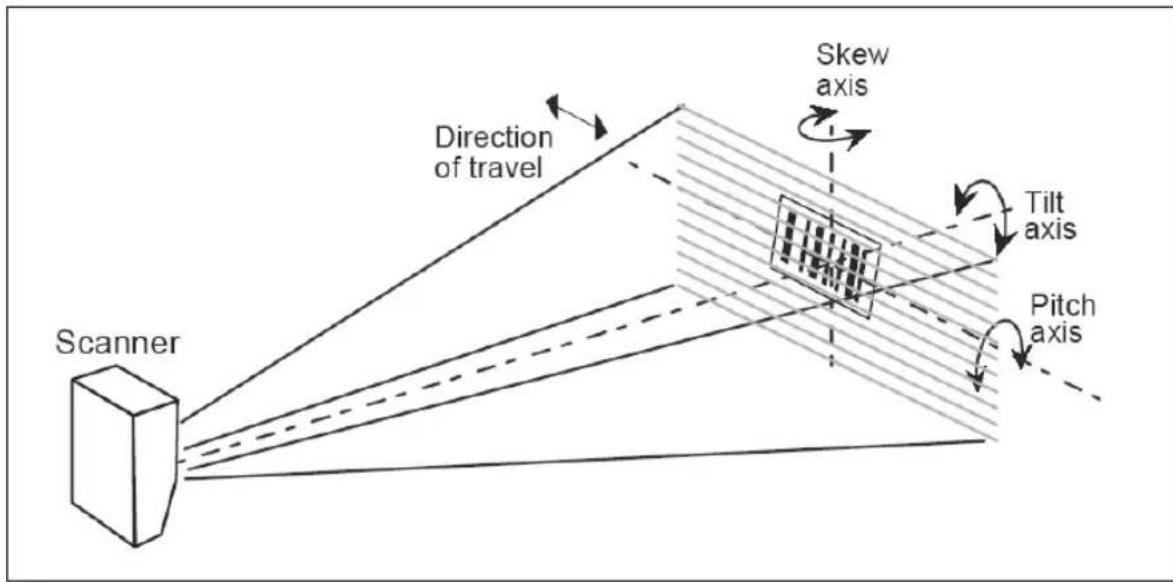
text_image
Direction of travel Skew axis Tilt axis Pitch axis ScannerScanner Position
Object Detector
Appendix H — Object Detector
In a typical operation, a scanner will wait for symbol data only during a triggered read cycle. A read cycle is initiated by a “trigger” and can be in the form of a serial command from the host (internal trigger) or a signal from an object detector (external trigger).
When an object detector (also called a sensor, package detector, etc.) is used, it is set up so that its beam will bounce off the approaching object and the resulting pulse will be sent to the scanner to begin the read cycle. Typically, a detector is positioned so that it will detect the presence of an object before its symbol can be scanned.
An object detector is mounted in almost any position relative to the object as long as:
(1) the object passes within range of the detector and
(2) direct or reflected light from the detector does not interfere with the scanner's reception.
As the item continues to move down the line, its symbol moves into the scanner beam and is read by the scanner.
The drawing below shows a symbol in the picket fence direction with the object detector positioned so as not to cause interference.
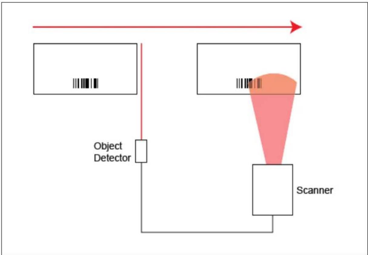
flowchart
graph TD
    A["Object Detector"] --> B["Object"]
    B --> C["Scanner"]
    C --> D["Signal Path"]
    D --> E["Output"]
Object Detector Operation
Appendix I — Bar Code Configuration
You can configure the MS-890 by presenting Code 128 symbols encoded with serial commands.
Note: Your scanner does not need to be enabled for Code 128 in order to enter Bar Code Configuration.
Entering Bar Code Configuration
The symbol used to enter configuration is the 7-character code 128 symbol shown below. It is not required that the scanner be configured to read code 128 symbols to read this start symbol or the following configuration symbols.
To set up Bar Code Configuration:
- Put the scanner in a read cycle mode.
- Place a special Code 128 configuration Start symbol (provided below) in the scanner's field of view.

text_image
If the scanner is able to read the Start symbol, it will begin to beep and the performance LEDs will activate.
- When the scanner starts to beep, remove the configuration symbol from the scanner's field of view.
The scanner is now in Bar Code Configuration mode.
During Bar Code Configuration mode, the LEDs will illuminate in a sequential pattern to indicate that the scanner is ready to be configured.
You can create your own start symbol by encoding the following character sequence in a Code 128 symbol:
FNC4 <_CFG>
Using Configuration Symbols
Once in Bar Code Configuration mode, serial command data encoded in Code 128 symbols is decoded by the scanner as serial input.
Configuration symbols must meet the following conditions:
- The only valid symbology for Bar Code Configuration is Code 128.
- Symbol data may contain more than one command, but individual symbols must be presented individually. This is because only the first symbol in a read cycle will be used as a possible configuration symbol. A symbol that is presented to the scanner must be read 25 times consecutively to be used as a valid symbol.
Once this is done, the scanner will interpret the symbol data in the same fashion as it interprets serial data.
- Any valid command may be encoded in Code 128 symbols, including operational commands.
Because the data is treated like serial input, multiple symbols may be used to represent one command as long as the symbols are presented individually and in the correct order.
-
Read Rate commands may also be used to enter Read Rate from Bar Code Configuration mode.
-
When in Read Rate, the scanner will read the symbologies that were enabled prior to entering Bar Code Configuration mode. However, the scanner will read a
in Code 128 regardless of the current enable/disable state of Code 128.
Once the
Scan the symbol shown to the right to start a Read Rate test.
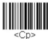
Exiting Bar Code Configuration
There are multiple ways of exiting Bar Code Configuration.
The first way is simply to decode a symbol encoded with the
Any command that executes a software reset will also end Bar Code Configuration mode. These commands include the Save family as well as the Reset family (
To end the Read Rate test and Bar Code Configuration mode, scan this symbol:

Configuration changes will remain in effect, as would changes made by using serial commands or ESP.
Appendix J — Test Read Rate
Test Read Rate by Bar Code Configuration
You can enter a Read Rate test by scanning the following symbols:
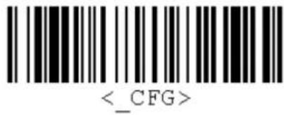
text_image
Enable Bar Code Configuration
(Also activates the scanner's read performance LEDs.)

Enable All Symbologies
Start Read Rate Test

End Read Rate Test and Disable Bar Code Configuration
Test Read Rate by Serial Command (Static Symbol)
- Position a stationary symbol in front of a functioning scanner at the scan distance used in your application.
- Set for single scan line scanning (Raster Top setting equal to Raster Bottom).
- Enter a
command to see the decodes per second.
The decode rate is the number of decoded scans per total number of scan. It will appear at the beginning of the data strings.
Note: You can also enter a
- Make a note of the decode rate. You will need this when calculating the number of decodes (see Appendix K, Formulas for Number of Decodes on page A-27).
- End the test by sending the
command.
Test Read Rate by ESP
See Read Rate in Chapter 12, Utilities.
Test Read Rate with a Moving Symbol
Before testing with a moving symbol, it is highly recommended that you calculate the expected number of decodes by using the formulas in Appendix K, Formulas for Number of Decodes on page A-27.
Once you've mounted the scanner, established a good read rate with a stationary symbol, and calculated the number of decodes for your symbol speed, you can begin decoding with moving symbols.
Number of Decodes
To ensure reliable scanning, you need to apply a minimum of five decodes to each symbol. This means that all variables, symbol speed, read range, etc. are significant.
Note: Variations between symbols are common. For this reason, the greater the number of sample symbols tested, the more likely you are to achieve optimum decode rates.
In general, the number of decodes of a given symbol can be increased by:
- Increasing symbol height
• Decreasing symbol length - Increasing scan rate (spinning mirror speed)
- Slowing symbol speed
• Decreasing raster sweep rate
• Decreasing raster height
Appendix K — Formulas for Number of Decodes
To ensure reliable scanning, apply a minimum of five decodes to each symbol. Use the formulas below to calculate the number of decodes that your symbol will receive.
If the number of decodes you derive from one of these calculations is less than the minimum for your application, plug in the minimum number of decodes (5) and solve for another parameter that might be changed, such as symbol speed or scans per second.
Note: While the formulas given here solve for the predicted number of decodes, you may also use the formulas to solve for other parameters that might be changed, such as symbol speed, symbol length, etc.
Single Line Ladder Calculation
Ladder scanning is seldom done with raster scanning unless the raster is set for single scan line scanning (Top Offset setting equal to Bottom Offset) or symbols are presented as stop-and-go.
For single scan line ladder scanning, use the following formula: ^1
$$ \mathrm{ND} = \left(\frac {\mathrm{SH}}{\mathrm{SS}} \cdot \mathrm{DR}\right) - 3 $$
ND (Number of Decodes) is the number of decodes that a given symbol can be expected to achieve in a given application.
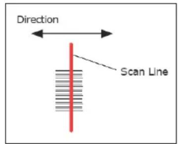
text_image
Direction Scan LineSingle Line Ladder Orientation
SH (Symbol Height) is a measurement of the height of individual bars.
SS (Symbol Speed) is the distance per second that a symbol moves through the scan.
DR (Decode Rate) is the number of scans per second that a given symbol receives.
Example:
SH = 0.5, SS = 10/second, and DR = 200 decodes per second
$$ \mathrm{ND} = \left(\frac {0 . 5}{1 0} \cdot 2 0 0\right) - 3 = 1 0 \text { complete decodes } $$
Raster Picket Fence Calculation
For raster picket fence scanning, the number of decodes (ND) that can be applied to a given symbol can be calculated once the sweep rate (SPS) is known.
Sweep Rate (Sweeps per Second)
Sweep rate is the number of raster sweeps (up or down) that occur per second and can be set in ESP. Since the sweep rate cannot exceed 30, you first need to ensure that your application can achieve this by solving for sweep rate (SPS). The sweep rate should generally be set as low as possible in order to maximize the number of scans on a given symbol.
The formula for finding Sweep Rate (SPS) is as follows:
$$ S P S = \frac {2 \cdot \mathrm{SS}}{(\mathrm{SW} - \mathrm{SL})} $$
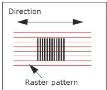
text_image
Direction Raster patternRaster Picket Fence Orientation
SPS = Sweeps per Second, the number of passes, up or down, that are described by the arc of the raster mirror.
SS = Symbol Speed, the inches per second that a symbol moves through the scan.
SW = Scan Width, the width across the scan beam, at a given distance from the scanner, in which a symbol can be read (picket fence formula only).
SL = Symbol Length, the length of the longest printed symbol to be read plus the length of the quiet zones (picket fence formula only).
Example:
$$ \begin{array}{l} \mathrm{SW} = 5 \ \mathrm{SS} = 2 \text { per second } \ \mathrm{SPS} = \frac {2 \cdot 2}{(5 - 1)} = 1 \ \mathrm{SL} = 1 \ \end{array} $$
Important: The maximum sweep rate that your can set the scanner to is 30. If your solution is greater than 30, you must change another parameter such as symbol speed, etc., and recalculate.
Since SPS can only be entered into the software as whole numbers, round off fractions of SPS to the next higher number, for example enter 0.4 as 1 and 3.5 as 4.
In setting up the scanner, raster height depends on the raster arc and the symbol distance (range) from the scanner. Both the top offset and bottom offsets can be adjusted independently in 255 increments and the resulting arc can vary from 0^ to 30^ . (See Chapter 10, Raster/Laser.)
Number of Decodes
Note: Because adjustable raster sweeps and scan speeds cannot be synchronized, some variation in raster height should be anticipated.
Number of decodes (ND) for a raster picket fence symbol is calculated by the following formula:
$$ \mathrm{ND} = \left(\frac {\mathrm{SH} \cdot \mathrm{DR}}{\mathrm{RH} \cdot \mathrm{SPS}}\right) - 3 $$
ND = Number of Decodes (total applied to each symbol)
SH = Symbol Height
DR = Decode Rate
RH = Raster Height
SPS = Sweeps per Second
Example:
$$ \mathrm{SH} = 1, \mathrm{DR} = 1 0 0, \mathrm{RH} = 1 0, \mathrm{SPS} = 1 $$
$$ \mathrm{ND} = \left(\frac {1 \cdot 9 0 0}{1 0 \cdot 1}\right) - 3 = 8 7 \text { decodes } $$
Raster Height
If raster arc (in degrees) and symbol range are known, raster height can be derived by the following formula, where is raster arc in degrees: ^1
$$ \mathrm{RH} = (2 \cdot \text { Symbol Range }) \tan \left(\frac {\neg}{2}\right) $$
Raster Arc
If raster height and symbol range are known, then raster arc can be derived by using the following formula where RH is raster height:
$$ \neg = 2 \cdot \operatorname{atan} \left(\frac {\mathrm{RH}}{2 \cdot \text {Symbol Range}}\right) $$
Note: Raster arc is not presented in degrees in ESP. To convert to degrees, add the Top Offset to the Bottom Offset and subtract the sum from 255. Enter this as the offset in the following formula:
$$ \text { Degrees } = \frac {\text { Offset } \cdot 3 0}{2 5 5} $$
Formulas for Number of Decodes
Single Line Picket Fence Calculation
For single scan line picket fence scanning (Top Offset setting equal to Bottom Offset), use the following formula:
$$ \mathrm{ND} = \left(\frac {(\mathrm{SW} - \mathrm{SL})}{\mathrm{SS}} \cdot \mathrm{DR}\right) - 3 $$
ND = Number of Decodes (total applied to each symbol)
SW = Scan Width
SL = Symbol Length
SS = Symbol Speed
DR = Decode Rate
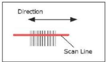
text_image
Direction Scan LineSingle Line Picket Fence Orientation
Example:
SL = 2 inches (including quiet zones)
SS = 100 inches per second
SW = 4 inches
DR = 1000 decodes per second
((4 - 2)100 · 1000) - 3 = 17 complete decodes
Angled Picket Fence Calculation
The number of complete scans for angled picket fence is calculated the same as that for picket fence, with the exception that the scan width is shortened in proportion to scan tilt.
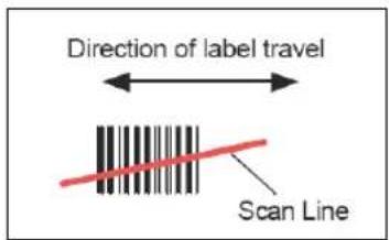
text_image
Direction of label travel Scan LineAngled Picket Fence Orientation
Improving Decode Rate
After changing any of the parameters described in this section, recalculate the number of decodes.
Scan Rate
Scan rate is a function of motor speed and is adjustable. A slower scan rate may allow greater symbol range and/or higher decode rates, but at the cost of fewer scans per symbol and scan width.
Range
Adjusting the symbol's range, if possible, is one of the quickest and most effective ways to improve decode rates. However, in some applications you may need to select a less than optimum range, or one that is beyond the fringes of the ranges.
Scan Width
Increasing scan width will increase the number of scans in a picket fence oriented application. Scan width is linked with scan range and changing one will usually require a change in the other.
Symbol Speed
Applies to both picket fence and ladder oriented symbols. If your application allows it, slowing symbol speed (the time in seconds that a symbol is fully within the scan width of the scanner) is an effective way to increase the number of decodes.
Raster Height
When using the raster features, you can increase the decode rate by decreasing the height of the raster image.
Raster Sweep Rate
Slowing the number of sweeps per second to the minimum needed will result in more scan lines passing over the symbol and a higher decode rate.
Laser Framing
Narrowing the laser frame may not increase the decode rate, but it will minimize the opportunity of extraneous reads.
Symbol Dimensions, Symbol Density, and Symbol Ratio
Not usually an option in most applications, but changes to symbol parameters can affect number of decodes calculations and possibly decode rates.
If your application allows it, shortening the length of a picket fence symbol means the symbol will be in the scan range longer and hence receive a greater number of scans. Increasing the height of a ladder symbol means it will receive more scans. Changing symbol density and/or symbol ratio is another way ranges, decode rates, etc. can be altered.
Gain and Tracking
These adjustments, typically made by qualified technicians, are referenced in the Scanner Setup menu (see Defaulting/Saving/Initializing on page A-18). Changes to tracking will generally have a limited effect on decode rates.
Appendix L — Operational Tips
Do:
- Check inputs (symbol speed, length, height, etc.) to ensure the desired number of decodes per symbol.
- For optimum decodes, mount scanner so that your symbols pass through the center of the depth-of-field (minimum/maximum range). You find the center by moving your symbol in and out during a read rate test.
- Avoid excessive tilt, pitch, and skew of the symbol.
- Check the symbol for readability by doing a decode rate test. If there is any question about the symbol's readability, contact your Microscan sales representative.
• After changing any parameter that might affect decode rate, repeat decode rate test. - Clean the scanner window with a clean, dry cotton swab or cotton cloth on a regular basis.
Do Not:
- Aim the scanner into direct light or sunlight.
- Aim the scanner into an external object detector or other light-emitting device.
- Obstruct the scanner window with mounting hardware or other objects.
- Connect chassis of scanner and host to different ground potentials.
- Operate the scanner in excessive temperature environments.
Appendix M — Interface Standards
Interface Standards, established by the Electronic Industries Association (EIA), specify such things as the signaling voltage levels, maximum cable lengths, and number of drivers. With Microscan devices, selection of interface is made by pin assignment and, in the case of the host communications, by software switching between RS-232 and RS-422. Microscan devices use RS-232, RS-422, and RS-485 multidrop.
RS-232
RS-232 defines an interface between two devices such as, for example, the scanner and host. It differs from the other interfaces by dedicating individual pins to specific functions and by requiring both devices to share a common ground line. Since both device chassis are connected to a common ground, a ground loop potential and the possibility of noise interference exists. Therefore cable lengths are limited to a maximum of 50 feet (19.7m). Despite being the most limited, this interface is used frequently because of the large installed base of RS-232 equipment.
RS-422
RS-422, unlike RS-232, measures signals deferentially; that is, the receiver looks at the potentials between the two receive (or transmit) wires rather than the potential between signal and ground. As a result, cables, if shielded, can be up to 4000 feet (1219m) in length. Like RS-232, RS-422 communication is designed for only two devices on a single line and must have a common ground. It can be used wherever RS-232 is used.
RS-485
RS-485, like RS-422, can transmit up to 4000 feet (1219 m) using differential voltages but unlike RS-422, its transmitters are turned off until a request for data is received from the host. RS-485 is used exclusively in Multidrop protocol.
Appendix N — Multidrop Communications
This appendix describes the rules for setting up a concentrator or controller to communicate with a scanner in standard Multidrop protocol.
The diagram to the right shows a typical Multidrop network in which 1 to 50 scanners can communicate with a host via an intermediary device, a concentrator, or a controller.
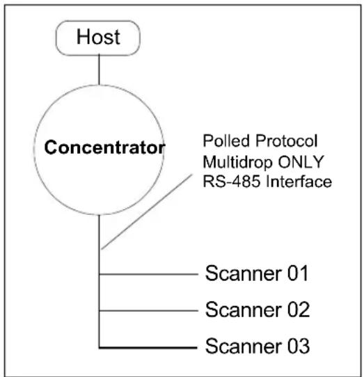
flowchart
graph TD
    A["Host"] --> B["Concentrator"]
    B --> C["Scanner 01"]
    B --> D["Scanner 02"]
    B --> E["Scanner 03"]
    B --> F["Polled Protocol Multidrop ONLY RS-485 Interface"]
Multidrop
Configure Scanner for Multidrop
- With the scanner connected to the host, Retrieve Reader Settings.
- Select Multidrop in the Protocol configuration menu.
You will see the following message:
Important: You must change your preamble and postamble characters so that they are not CR or NUL.
This allows data to move through the concentrator without interference.
- Click OK.
- Next, go to Preamble Characters (still in the Protocol menu) and double-click on Characters.
- This will open up an ASCII character table. Select any character but CR.
- Repeat the above process for Postamble.
- Check the multidrop address. Enter a number from 01 to 50.
- Right-click in the window and select Save to Reader and Send and Save.
- Your scanner is now in Multidrop. From here on, you will need to use the concentrator to relay commands and data between the scanner or scanners and the host.
- Move on to Connect to Scanner via Concentrator.
Connect to Scanner via Concentrator
You will need a multidrop concentrator and the required power supplies and cabling to communicate with your scanner(s).
- From the Communications dropdown menu in the menu toolbar, select Configure Multidrop. The Multidrop Settings dialog will appear.
- If necessary, change the default address to match the address of your multidropped scanner and click OK.
If the host serial port is not connected in ESP, you will see the following popup message:
"ESP is not currently connected to the multidrop concentrator. Do you wish to establish a connection now?"
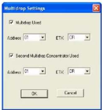
text_image
Multidrop Settings ✓ Multidrop Used Address 01 ETX CR ✓ Second Multidrop Concentrator Used Address 01 ETX CR OK Cancel- Click Yes.
- The Connection Settings dialog will appear. Notice that the Force Connect option is checked. Do not change this.
- Select the concentrator's host port communications settings.
When you click Connect, you will be connecting to your concentrator, which can then relay commands to the scanner whose address was set in the Multidrop Settings dialog.
- Click Connect.
You should see the CONNECTED message in green at the bottom of the window along with the scanner's Multidrop address.
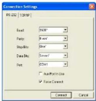
text_image
Connection Settings RS-232 | TCPMP Baud: 9600° Patty: Even' Stop Bit: One' Data Bit: Seven' Port: COM1 □ Back Port In Use ☑ Force Connect Connect Cancel
- Click Retrieve Reader Settings to upload the scanner's configuration. If upload fails, return to the Connection Settings dialog and make the necessary parameter changes.
- Follow the same procedure for connecting other scanners to your multidrop network.
Polling Sequence
Data that is transmitted to the host (symbol data, No Read messages, counters, etc.) via concentrators is solicited by poll requests from the host.
The polling sequence example by poll address 1E (ASCII hex value for Scanner 02) and a REQ (request). The scanner responds by first transmitting its own address, 1E, followed by a STX (start of text) character, and then the data. Next it transmits an ETX (end of text) character and an LRC (longitudinal redundancy check) character.
If the concentrator (or controller) receives the data from the scanner and is able to validate it with an LRC calculation, it responds with an ACK (acknowledgment). If the scanner in turn receives the ACK, the scanner ends this successful exchange with a RES (reset).
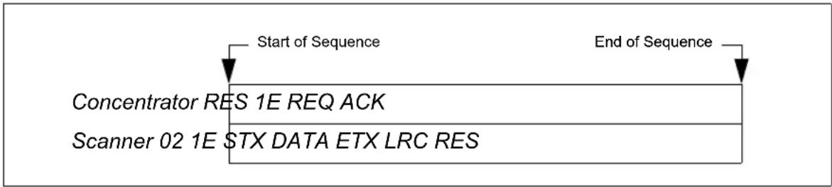
flowchart
graph LR
    A["Start of Sequence"] --> B["Concentrator RES 1E REQ ACK"]
    B --> C["Scanner 02 1E $TX DATA ETX LRC RES"]
    D["End of Sequence"] --> E["End of Sequence"]
Polling Sequence
Polling Reset
- If the scanner has no information, it responds to a poll request by transmitting a RES (reset).
- If the scanner receives a NAK instead of the ACK after transmitting its data string, it will re-attempt to send the data string up to three times. If the scanner still does not receive an ACK, it will send a RES (reset) and discard the data in its buffers.
- If the scanner transmits data to the concentrator and the concentrator responds with an ACK or NAK, but the scanner doesn't receive the concentrator's response, the scanner will timeout and send a REQ to the concentrator and request another response. If after three retries (the number of times it transmits a REQ to the concentrator) the scanner receives no response, it ends the transmission with a RES (reset).
Select Sequence
Unlike poll requests, select commands always originate from the host and consist of serial configuration or operation commands to devices that are configured in Multidrop. The scanner complies with the command when it is polled during the cycle.
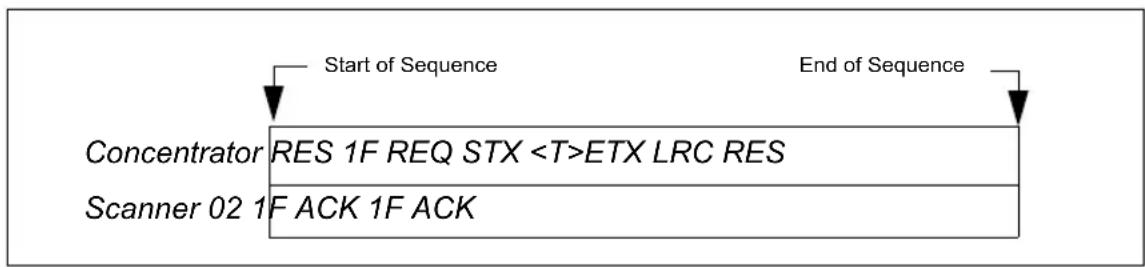
flowchart
graph LR
    A["Start of Sequence"] --> B["Concentrator RES 1F REQ STX <T>ETX LRC RES"]
    B --> C["Scanner 02 1F ACK 1F ACK"]
    D["End of Sequence"] --> E["End of Sequence"]
Polling Sequence
A RES (reset) is the first command in the select sequence. The 1F hex is the select address associated with Scanner 02 address. It is followed by a REQ (request). The scanner responds with its own select address, 1F hex, and an ACK (acknowledge). The concentrator then transmits an STX (start of text), the data (in this case a
The scanner replies by transmitting its own address, followed by an ACK, acknowledging receipt of the command. Upon receipt of an ACK, the concentrator concludes the successful exchange with a RES.
In the example above, the scanner only acknowledges a trigger counter request from the concentrator. It does not respond to the trigger counter request until a subsequent poll. For example, if the scanner's trigger count was 12 at the time the trigger counter request was received, on a subsequent poll it would send 02T/00012. (The 02 at the beginning of the string is the scanner's address.)
Select Reset
If the scanner receives bad data from the concentrator, it transmits a SEL (its select address) and a NAK to the concentrator. The concentrator re-transmits the data up to three times. The concentrator will end the sequence with a RES (reset) if no ACK is received.
Multidrop Addresses
| Multidrop Address | Poll Character | Select Character | Multidrop Address ASCII HEX | Poll Character | Select Character | ||||
| ASCII HEX ASCII HEX ACII HEX | |||||||||
| 01 ^ 1C | ^] 1D 26 | N 4E O 4F | |||||||
| 02 ^^ 1E | ^- 1F 27 | P 50 Q 51 | |||||||
| 03 SP 20 | ! 21 | 28 R 52 S | 53 | ||||||
| 04 | " | 22 | # | 23 | 29 | T | 54 | U | 55 |
| 05 | 24 % | 25 30 V 56 W 57 | |||||||
| 06 | & | 26 | ' | 27 | 31 | X | 58 | Y | 59 |
| 07 | (28) | 29 32 Z | 5A | [5B | |||||
| 08 | * | 2A | + | 2B | 33 | \ | 5C | ] | 5D |
| 09 | , | 2C | - | 2D | 34 | ^ | 5E | _ | 5F |
| 10 | . | 2E | / | 2F | 35 | ` | 60 | a | 61 |
| 11 | 0 | 30 | 1 | 31 | 36 | b | 62 | c | 63 |
| 12 | 2 | 32 | 3 | 33 | 37 | d | 64 | e | 65 |
| 13 | 4 | 34 | 5 | 35 | 38 | f | 66 | g | 67 |
| 14 | 6 | 36 | 7 | 37 | 39 | h | 68 | i | 69 |
| 15 | 8 | 38 | 9 | 39 | 40 | j | 6A | k | 6B |
| 16 | : | 3A | ; | 3B | 41 | l | 6C | m | 6D |
| 17 | < 3C = 3D 42 | n 6E o | 6F | ||||||
| 18 | > | 3E | ? | 3F | 43 | p | 70 | q | 71 |
| 19 | @ | 40 | A | 41 | 44 | r | 72 | s | 73 |
| 20 | B | 42 | C | 43 | 45 | t | 74 | u | 75 |
| 21 | D | 44 | E | 45 | 46 | v | 76 | w | 77 |
| 22 | F | 46 | G | 47 | 47 | x | 78 | y | 79 |
| 23 | H | 48 | I | 49 | 48 | z | 7A | { | 7B |
| 24 | J | 4A | K | 4B | 49 | | | 7C | } | 7D |
| 25 | L 4C M 4D 50 | ~ 7E D 7F | |||||||
Appendix O — Glossary of Terms
Active Closed — An optoisolated input-output that's logically "on" when current flows through the connection points.
Active Open — An optoisolated input-output that's logically "on" when no current flows through the connection points.
Analog Gain Adjustment (AGC) — Adjustment to signal strength that seeks to maintain a constant level regardless of the range of the symbol.
Application Record — A variation of EAN-128 which adds an application identifier to symbol data, including user-definable separators, brackets, and padding.
Autocalibration — A routine that cycles through various optical settings and selects the combination that produce the best read rate.
Autodiscrimination — The ability to decode several different symbologies without changing configuration.
Auto Range — Outward focus of the scanner until an object is sensed by signal strength. The scanner then begins searching for a decodable symbol.
Auxiliary Port — Auxiliary terminal connection for remote viewing and command inputs.
Bar Code — A symbol in which data has been encoded in an array of parallel bars and spaces of varying widths.
Baud Rate — The number of discrete signal events per second. Bits per second.
Channel — A high-speed pathway between the computer and the control units of the peripheral devices.
Check Digit — A Modulus 43 or Modulus 10 digit that is added to the symbol data for additional data integrity.
Command Processing — Allows the user to enter ESP from the Aux Port or send serial string commands from the Aux Port.
Configuration — A setup or process of changing a scanner's settings to conform to a specific application.
Concentrator — Intermediary device that relays data from scanners to a host and commands from the host to the scanner or other devices.
Connector — Physical device (plug or socket) on a device or cable to provide in/out connectivity for various circuits and pins.
Counter — Memory space provided to keep track of scanner events.
Daisy Chain — Linkage of scanners to allow data to be relayed up to the host via Aux Port connections.
Decode — A Good Read. The successful scanning and decoding of the information encoded in a symbol.
Default — Restores ROM settings and resets the scanner.
Delimited — A command or field that is bracketed by pre-defined characters.
Decode Rate — The number of good reads per second decoded by the scanner.
Glossary of Terms
Depth of Field — The distance between the minimum and maximum range in which a scanner can read symbol.
Discrete I/O — Inputs and outputs characterized by discrete signal transitions.
EPROM — Erasable, programmable, read-only memory.
Embedded Memory — Onboard memory device such as EPROM or flash.
End of Read Cycle — The time or condition at which the scanner stops expecting symbol data to decode.
External Edge — Allows a read cycle to be initiated by a trigger signal from an object detector when it detects the appearance of an object (rising edge). The read cycle ends with a good read, a timeout, or a new trigger.
External Level — Allows a read cycle to be initiated by a trigger signal from an object detector. The read cycle ends when the object moves out of the detector's range.
Fixed Symbol Length — Increases data integrity by ensuring that only one symbol length will be accepted.
Flash Memory — Memory that can be changed by downloading new code.
Focal Length — The distance measured from the scanner to the center of the depth of field, or focal point.
Focus — The point at which the tip of the scan beam is at its narrowest.
Full Duplex — Auxiliary port data is sent directly to the host but not displayed on the auxiliary port screen.
Gain — Optimal signal strength.
Good Read — A decode. The successful scanning and decoding of the information encoded in a symbol.
Half Duplex — Auxiliary port data is sent directly to the host and displayed on the auxiliary port screen.
Intercharacter Delay — The time interval in milliseconds between individual characters transmitted from the scanner to the host.
Intercharacter Gap — The extra space between the last element of one character and the first element of the adjacent character of a specific symbol.
Ladder Orientation — An orientation in which a symbol's bars are parallel to its direction of travel.
Large Intercharacter Gap — Allows the scanner to read symbols with gaps between characters that exceed three times (3x) the narrow element width.
Laser Framing — Setting scan width size by adjusting the on/off duration of the laser beam.
Laser On/Off — When enabled, the laser is ON only during the read cycle, provided the scanner is enabled for a Serial or External trigger.
LED — Light emitting diode.
Longitudinal Redundancy Check (LRC) — An error-checking routine that verifies the accuracy of transmissions.
Matchcode — The ability to compare symbols being scanned against a master symbol that is stored in the memory of the scanner.
Embedded Menu — Configuration options embedded in the scanner's erasable memory.
Mil — One thousandths of an inch or 0.0254 mm. In bar coding, a measurement standard that measures a symbol by the width of its narrowest element.
Mismatch — An event that occurs when the scanned symbol does not match the master symbol that is stored in the memory of the scanner.
Multisymbol — A scanner mode which allows a scanner to read more than one symbol in a single read cycle.
Multidrop — A communications protocol for networking two or more scanners or other devices with a concentrator (or controller) and characterized by the use of individual device addresses and the RS-485 standard.
Narrow Bar Width — The width of the narrowest bar of a given symbol, expressed in thousands of an inch (or mils).
Narrow Margins — Allows the scanner to read symbols with quiet zones less than 8 times the width of the narrow bar element.
Non-Delimited — A command that is not bracketed by pre-defined characters.
Non-Volatile RAM (NOVRAM) — Random Access Memory that is available on power on; that is, after power to the unit has been recycled.
No Read — A failed decode attempt. A condition that occurs when the scanner is set up to decode symbols but no symbol is scanned during the read cycle.
NOVRAM — Non-volatile random access memory. Data that is saved for “power on” is saved to NOVRAM.
Number of Decodes — The number of times a symbol is scanned by the scanner during one pass through the laser beam.
Object Detector — A photoelectric device used to sense the presence or absence of an object (also referred to as a package detector).
Output — To transfer or transmit from the computer to a peripheral device or communications line. A channel or communications line. Decoded data or discrete signal.
Output Format — The modification of data output according to a user-defined index of Extraction and Insertion commands.
Parity — An error detection routine in which one data bit in each character is set to 1 or 0 so that the total number of 1 bits in the data field is even or odd.
Picket Fence Orientation — An orientation in which a symbol's bars are perpendicular to its direction of travel.
Pitch — Symbol (or scanner) rotation around the center of a line perpendicular to the symbol's bars.
Point-to-Point — A protocol consisting of a single communications event, typically used to connect a scanner to a terminal or host computer.
Port — Logical circuit for data entry and exit. (One or more ports may be included within a single connector.)
Glossary of Terms
Protocol — The rules for communication between devices, providing a means to control the orderly flow of information between linked devices.
Quiet Zone — Specified “clear” (nonprinted) area immediately before and after the symbol. The area is usually white (for black and white symbols) and at least 10 times the width of the narrowest bar, as measured in thousands of an inch. The quiet zone can be a shade or color other than white as long as its density remains consistent and it has the required contrast relative to the bars.
RAM (Random Access Memory) — Memory that is lost after power is recycled to the unit.
Raster — Multiple stacked scans produced by a separate oscillating mirror or by a spinning mirror with varying facet angles.
Read Cycle — A programmed period of time or condition during which the scanner will accept symbol input.
Read Range — The distance within which a symbol can be read reliably, as measured from the front of the scanner.
Relay — An electrical switch that allows a low power to control a higher one.
Reset — Clears current data and initializes counters and configuration parameters.
ROM (Read-Only Memory) — Memory that cannot be changed.
Scanner — A scanning device that is comprised of a scan head and a decoder integrated in one package.
Scan Rate (SR) — The number of decodes per second that a given scanner is capable of casting.
Scan Width (SW) — The width across the scan beam at a given distance from the scanner in which a symbol can be read.
Separator — A character that separates data fields.
Serial Commands — Online data strings such as sent from a host or auxiliary terminal to a scanner or other device. Serial Configuration (Host Configuration) — Serial command specifically for changing configuration and distinguished from operational command by the fact that they modify the non-volatile for power up configuration. Skew — Symbol (or scanner) rotation around the center of the skew axis. Specular Reflection Zone — The narrow zone straight out from the scanner in which direct reflected light from a symbol can distort the scanner's ability to distinguish bars from spaces. Supplemental — A character or data string that is appended to the main symbol. Sweep — One pass of the raster, up or down. Sweep Rate (SwR) — The number of passes per second, up or down, describing the raster image. Symbol Density — The number of characters per inch (or other unit of measure) encoded in a symbol. Symbol Height — Regardless of orientation, the measurement taken along the length of a symbol's individual bars. Symbol Length — Regardless of orientation, the measurement taken across the symbol's bars from one end to the other, including the quiet zone. Symbology — A set of symbols, such as Code 39 or Code 128, that have special rules to define the widths and positions of bars and spaces to represent specific numeric or alphanumeric information. Symbology ID — An AIM standard prefix character that identifies the symbol type. Symbol Speed — The distance per second that a symbol moves as it travels through the scan lines. Symbol Transitions — The transition of bars and spaces on a symbol, used to detect the presence of a symbol on an object. Tilt — Symbol (or scanner) rotation around the center line of the scan beam. Timeout — A user-selected period of time that ends a scanner's read cycle. Tracking — Adjustment of the precision of analog-to-digital conversion. Transparent — Data is passed between the auxiliary port and the host with keyed data echoed to the auxiliary port Trigger — A signal, transition, or character string that initiates a read cycle. TTY — Abbreviation for JeleTYPewriter. This is a device that sends information character by character over an analog line. Watchdog Timer — A security device that detects system crashes and attempts to reset the scanner. Watchdog Reset — A reset that is forced whenever the software locks up. Wildcard — User-defined character entered into a master symbol to permit matches with variable characters. Glossary of Terms