50 - Outboard motor Raider - Free user manual and instructions
Find the device manual for free 50 Raider in PDF.


User questions about 50 Raider
0 question about this device. Answer the ones you know or ask your own.
Ask a new question about this device
Download the instructions for your Outboard motor in PDF format for free! Find your manual 50 - Raider and take your electronic device back in hand. On this page are published all the documents necessary for the use of your device. 50 by Raider.
USER MANUAL 50 Raider
40 and 50 Horsepower
Two stroke Low pressure Direct Injection (TLDI)
Multi-Fuel SubmersibleOutboard Motor
text_image
nual RAIDER power pressure Direct TversibleOutboard MotorThis manual has been prepared for the United States Guardian Angels for service of the Multi-fuel, Submersible Outboard motor designed and manufactured under Contract No. N61331•11•C-0008, dated 3/4/11. The data presented in this manual was revised as of August 2013 representing the latest revision.
Contents
- Your Raider Outboard Motor 1
a. Limited Warranty 1
b. Serial Number 1
c. Safety/Danger/Warnings/Cautions.... 1
d. Features of Raider Outboard 1
e. Specifications Table.... 3
f. TLDI verses Carburetor 4
g. TLDI RAIDER Parts Identification 5
- Raider Installation 6
a. Handling Engine 6
b. Installation of single Engine 6
c. Installation of Twin Engines....7
d. Installation of Safety Wire 7
e. Transom Height 7
f. Propeller 8
- Raider Running 9
a. Fuels (Multi-fuel)....9
b. Raider Break in....9
c. Normal Starting Procedure....9
d. After Raider Starts/Warm Up....10
e. Forced engine oil feeding 10
f. Idle Speed 10
g. Throttle Friction....11
h. Shifting 11
i. Stopping Raider 12
j. Trim Angle....12
k. Trailering....12
I. Tilting....12
m. Trim Tab Adjustment....13
n. Shallow Water Drive 13
o. Shallow Water Operation....13
p. Impact Damage 14
q. Special Operating Conditions ....14
r. Overheating....14
s. Emergency Starting 15
t. Pre-Submersion Procedure 16
u. Dewater Procedure....16
v. Post Submersion Procedure ....17
- General Maintenance 18
a. Fuel/Oil Requirements....18
b. Removing and Carrying the Raider....19
c. Tool Kit and spare parts 20
d. Corrosion Protection....20
e. Optional Accessories....20
f. Trouble shooting....21
g. Storage....21
h. Out of Storage Service 22
i. After Submersion....23
1. Your Raider Outboard Motor
a. Limited Warranty
This Raider product is fully guaranteed against defective materials and workmanship for the period on one year. The limited warranty will not apply to normal wear and tear of parts, adjustments, tune-ups, or to any damage caused, but not limited to careless use.
Raider has taken every advantage using non-corrosive materials, high quality and high reliable parts. This multi-fuel, submersible outboard has been built for ruggedness and durability to meet war fighter's needs.
The limited warranty does not cover maintenance items. The following items are a few examples not covered by the limited warranty: spark plugs, Anode, Propeller, Fuel filter, Oil filter, Starter rope, Shear-pin, Rubber goods, water pump impeller, oil seal, vinyl tubing, and battery if that option has been selected.
The limited warranty will not cover the boat the product is mounted on, trailer, equipment, or accessories associated with the product.
b. Serial Number
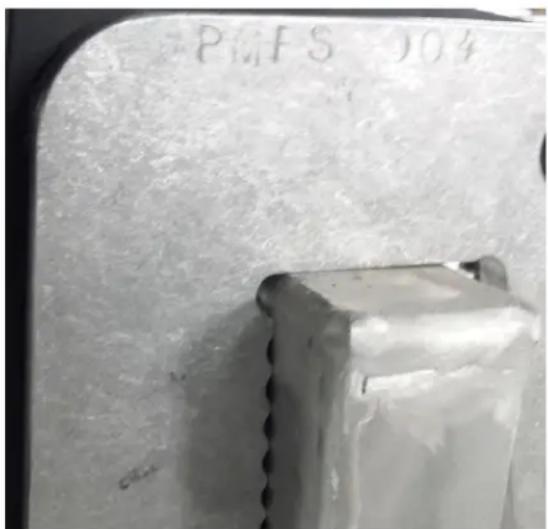
The serial number is engraved on the side of the transom mount.
c. Safety/Danger/Warnings/Cautions
Before operating the Raider outboard motor, be sure to thoroughly read and understand this Users manual and follow all of the instructions shown. Of particular importance information preceded by the words or symbols draw attention to safety issues. This manual contains information that can help prevent personal injury and damage to equipment. Understand the following symbols before proceeding:
! Safety Warning
Alerts you to the possibility of danger and identifies information that will help prevent injuries.
Identifies information that will help prevent damage to machinery.
? Appears next to information that controls correct assembly and operation of the product.
! Safety Warning: When replacement parts are required, use genuine Raider parts, or parts with equivalent characteristics, including type, strength, and material. Failure to do so may result in product malfunction and possible injury to the operator and/or passengers.
* All photographs and illustrations used in this manual may not depict actual models or equipment, but are intended as representative views for reference only.
d. Features of Raider Outboard
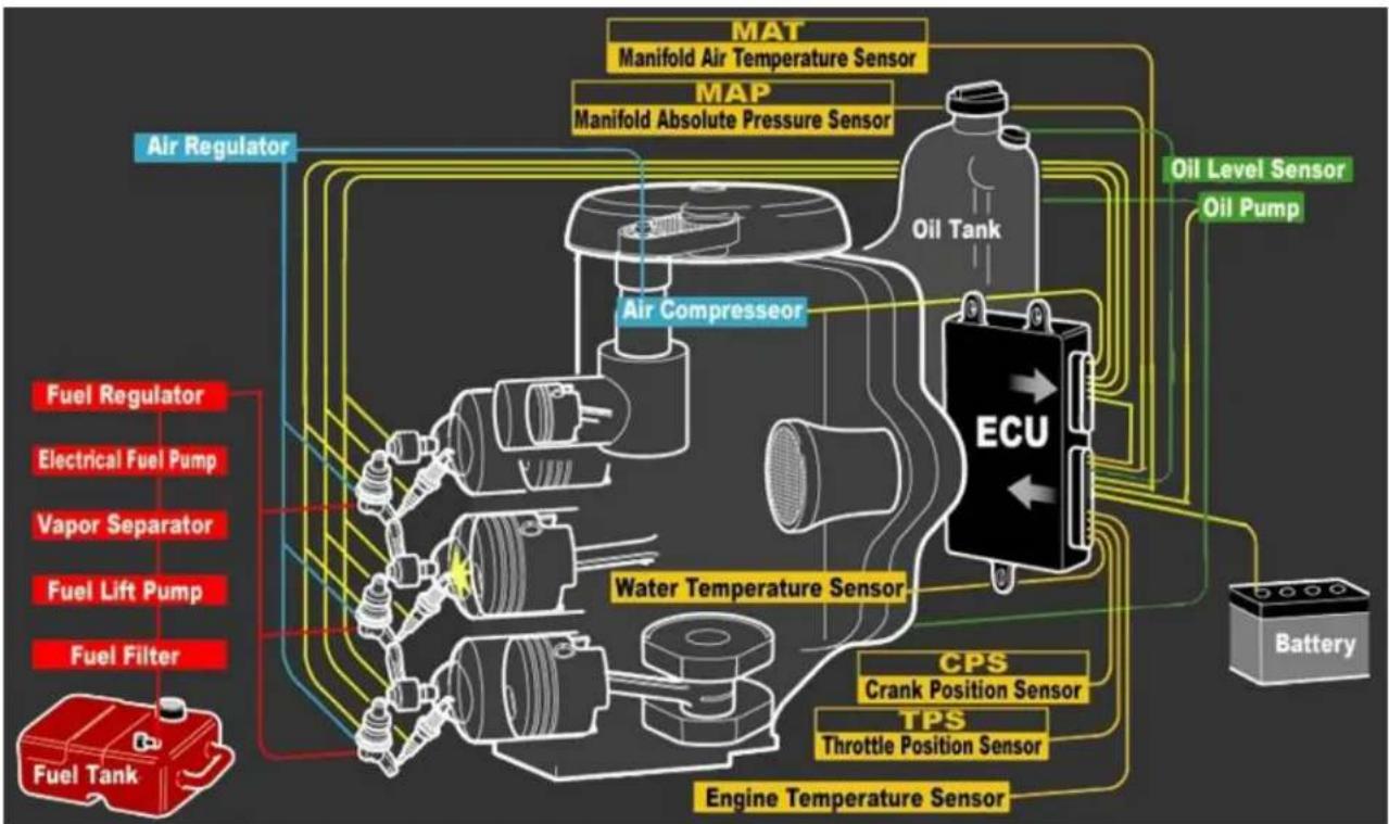
Raider's new TLDI 50 represents a quantum leap forward in outboard engine technology. The beauty of the TLDI 50 is its simplicity. It's based on the supply chain of the
Tohatsu/Nissan M50D2 and apart from fuel and air delivery modifications, with the addition of a sophisticated engine management system that supports submersibility and multi-fuel operation; it's still a two-stroke engine no other engine can match in terms of reliability.
flowchart
graph TD
    A["Fuel Tank"] --> B["Fuel Regulator"]
    B --> C["Electrical Fuel Pump"]
    C --> D["Vapor Separator"]
    D --> E["Fuel Lift Pump"]
    E --> F["Fuel Filter"]
    F --> G["Air Regulator"]
    G --> H["Manifold Air Temperature Sensor"]
    G --> I["Manifold Absolute Pressure Sensor"]
    H --> J["Oil Level Sensor"]
    I --> K["Oil Pump"]
    J --> L["ECU"]
    K --> L
    L --> M["CPS"]
    L --> N["Crank Position Sensor"]
    L --> O["TPS"]
    L --> P["Throttle Position Sensor"]
    M --> Q["Engine Temperature Sensor"]
    N --> Q
    O --> Q
    P --> Q
    Q --> R["Battery"]
There is an air compressor, an air/fuel rail, and six injectors. Three fuel injectors introduce fuel into the air/fuel rail. 80 PSI fuel and air are mixed and then injected into the combustion chamber through three air injectors after the exhaust port is closed. The result is complete atomizing without having to resort to high fuel-injection pressures. A single-throttle body air intake incorporates Throttle Position Sensors for load and barometric pressure (to ascertain the correct air/fuel ratio) and along with the air; lubricating oil is carried via the crankcase to the combustion chamber. For ease of servicing the six injectors are contained in a neat extruded aluminum block, held in place to the cylinder head by just two bolts.
The 40 Raider horsepower outboard uses 90% of common 50 Raider outboards outside of engine block and heads. The Raider 40 only has two cylinders, weight under 150 pounds.
The Raider 50 & 40 offers multi-fuel operation, submersibility, no battery required, (however, this option of an enclosed battery with electric start under the cowling can be ordered), pull start, small enough to go through a submarine hatch and strong enough to operate after an air drop. It offers superior human factors design for the operator. It is lighter than any outboard motor in its class.
The Raider Outboard was designed, under contract by SOCOM, to provide an outboard that was specifically designed to the toughness of military requirements and fully submersible without bags with the ability to be cached.
What all this means for the war fighter is an outboard that is consistent, reliable, lightweight, and durable that operates on most available fuels. When submerged the Raider can be de-watered quickly - complete the mission and get home with confidence.
e. Specifications Table
| ITEM | RAIDER 50 HP TLDI |
| Overall length | 1120 mm (44.1 in.) |
| Overall width | 384 mm (15.1 in.) |
| Overall height | 1514 mm (59.6 in.) |
| Weight | 92.0 kg (202 lbs.) - w/o composites |
| Transom length | 530 mm (20.9 in.) |
| Engine type | 2-Stroke Direct Injection |
| Piston Displacement | 697 ml (42.5 cu. In.) |
| Bore and Stroke | 68 mm (2.68 in.) x 64 mm (2.52 in.) |
| Number of cylinders | 3 |
| W.O.T. | 5150 - 5850 rpm |
| Trolling | 700/800/900 rpm - 3 stages available |
| Idling | 700/800/900 rpm - 3 stages available |
| Full throttle fuel consumption (approximately) | 17 L/Hr (4.5 US gal/Hr) varies per fuel selection |
| Starting System | Pull Start; rope backup (electric start available with battery under cowl) |
| Intake System | Reed Valve |
| Scavenging system | 5-port loop Charge |
| Exhaust system | Through hub |
| Lubrication system | Oil injection |
| Cooling system | Water-cooling |
| Water temperature control | Thermostat (with pressure relief valve) |
| Ignition System | Inductive |
| Ignition timing control | Electronics Control Unit (ECU) |
| Firing Order | 1-2-3 |
| Spark Plug | NGK: PZFR6H |
| Alternator | 12V 280W (Maximum) |
| Battery | Not required–optional (lightweight lithium iron phosphate battery under cowl) |
| Trim Angle | 4-24 degrees |
| Trim Angle settings | 6 degrees |
| Maximum tilt-up angle | 75 degrees |
| Transom board thickness | 31-70 mm (1.22 - 2.76 in.) |
| Maximum steering angle | 80 degrees |
| Gear shift | Dog clutch (F-N-R) |
| Gear ratio | 1:85 (13 : 24) |
| Throttle Control | Tiller Handle |
| Fuel Tank | Furnished by customer – normal fitting |
| Oil Tank | 2L (2.1US qt.) |
| Fuel | JP5/8/diesel/kerosene/fuel |
| Engine Oil | Genuine MD Gold or Equivalent |
| Gear Oil | API GL5, SAE#80 to #90 500 ml (16.89 fl. Oz.) |
| Submersibility | 66 ft/18 hours; 50 ft./24 hours |
| Handling/grab rails | Attached – fits through submarine hatch |
f. TLDI verses Carburetor
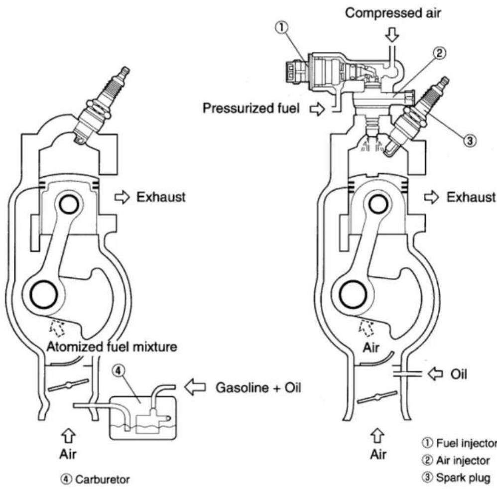
TLDI is an abbreviation that stands for Two-stroke Low-pressure Direct Injection.
The air assisted, low-pressure direct injection system has been combined with the inducted ignition system and the Engine Control Unit, which performs control or fuel mixture, injection timing and ignition timing to maximize combustion efficiency in the TLDI engine. The result is better fuel economy, lower maintenance, ability to burn multi-fuels and capable of submersion.
The air-assisted Low-pressure direct fuel injection process involves using an air compressor to pressurize the fuel supplied by the fuel pump and inject it directly into the combustion cylinder in the form of a finely atomized mixture that achieves maximum combustion efficiency.
Below is a simple diagram of how the TLDI engine operates and the conventional carburetor engine to show the differences.
text_image
Compressed air Pressurized fuel Compressed air Exhaust Atomized fuel mixture Gasoline + Oil Air ④ Carburetor ① Fuel injector ② Air injector ③ Spark plug Air Oilg. TLDI RAIDER Parts Identification
text_image
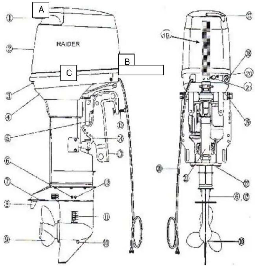
RAIDER A B C ① ② ③ ④ ⑤ ⑥ ⑦ ⑧ ⑨ ⑩ ⑪ ⑫ ⑬ ⑭ ⑮ ⑯ ⑰ ⑱ ⑲ ⑳ ㉑ ㉒ ㉓ ㉔ ㉕ ㉖ ㉗ ㉘ ㉙ ㉚ ㉛ ㉜ ㉝ ㉞ ㉟ ㉟a ㉟b ㉟c ㉟d ㉟e ㉟f ㉟g ㉟h ㉟i ㉟j ㉟k ㉟l ㉟m ㉟n ㉟o ㉟p ㉟q ㉟r ㉟s ㉟t ㉟u ㉟v ㉟w ㉟x ㉟y ㉟z① Tilt Handle
② Top Cowl
③ Hook Lever
④ Water Check Port
⑤ Tilt Stopper
⑥ Water Plug
⑦ Anti-ventilation Plate
⑧ Trim Tab
⑨ Propeller
⑩ Oil Plug (lower)
⑪ Water Strainer
⑫ Oil Plug (upper)
⑬ Clamp Bracket
⑭ Thrust Rod
Clamp Screw
⑰ Filler Ltd
18 Fuel Connector
19 Tiller Handle
20 De-Watering Valve
21 Pressure Relieve Valve
A Rear dewatering valve
B Front dewatering valve
C Mid dewatering valve
2.
Raider Installation
a. Handling Engine
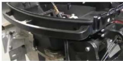
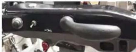
! The Raider was designed to be carried by the two side rails installed to allow the outboard to be moved through submarine hatches and small areas. The handle/shifter should be upright into the hollow area to keep from getting damaged and to help in carrying the Raider. Be aware of the sharp propeller when lifting through submarine hatches.
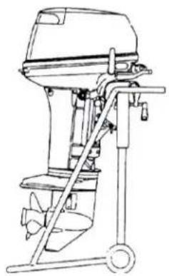
To move engine around shop area, use a motor stand that supports engine by the transom mount.
natural_image
Close-up of a black automotive component with visible wiring and mounting brackets (no text or symbols)Hand Rails – Both Sides for Carrying
WARNING
Most Rubber Inflatable Boats are rated and certified in terms of their maximum horsepower on the transom. This information is shown on the boat's certification plate. Do not equip your RIB with an outboard that exceeds this limit.
Do not operate the engine until it has been securely mounted on the boat in accordance with the instructions. Attach safety wire to boat to avoid losing the motor overboard.
b. Installation of single Engine
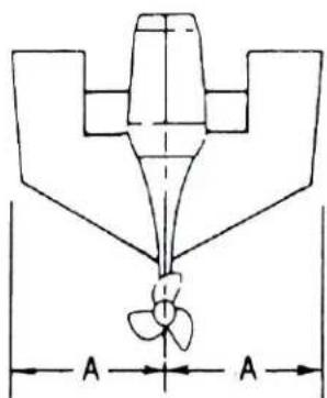
The Raider has been designed to be released from submarines and air dropped. This installation will discuss a typical installation – no special operations installation. Position the outboard engine at the exact center of the stern and mount it against the Rubber Inflatable Boat pad or plate. It is important to keep it centered as much as possible, Tighten clamp screws by hand DO NOT use tools to tighten clamp screws. Retighten engine clamps after 15 minutes of operation.
natural_image
Technical line drawing of a mechanical component with dimension lines labeled A (no text or symbols present)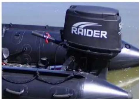
natural_image
Close-up of a black rigid-hulled inflatable boat with 'RAIDER' branding, partially submerged in water (no visible text beyond branding)c. Installation of Twin Engines
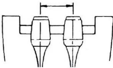
When installing two outboard engines, be sure to keep an interval of 470 to 600 mm (18 to 26 inches) between the two engines. Both outboard engines should be at the exact center of the stern and mount it against the Rubber Inflatable Boat pad or plate. It is important to keep it centered as much as possible, after centering on transom tighten clamp screws of both motors by hand. The attachment of a single steering unit for dual mount assembly can be quickly placed on dual motors for control and a cable inserted from one engine to the opposite for single power to both outboards.

18 to 26 inches apart
natural_image
Pure mechanical component diagram without any text, numbers, or symbols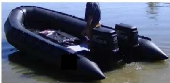
natural_image
Person in an inflatable boat floating on water, no visible text or symbolsd. Installation of Safety Wire
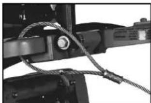
To prevent loss of engine (engines) overboard, attach engine retention cable that is attached to the Raider outboard to the boat.
e. Transom Height
natural_image
Close-up of mechanical components with coiled wires and a central knob (no visible text or symbols)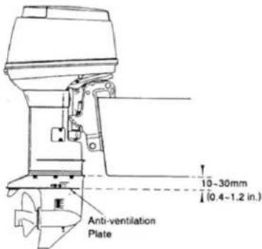
text_image
10-30mm (0.4-1.2 in.) Anti-ventilation PlateThe Raider has been designed to have the anti-ventilation plate at a level 10 to 30 mm (0.4 to 1.2 inches) below the bottom of the boat as shown above. Be sure the anti-ventilation plate of the Rader outboard is below the water surface when running with wide open throttle.
CAUTION
Overheating may occur if Anti-ventilation plate is at higher level than the boat as a lack of cooling water.
f. Propeller
A propeller must be selected so that the engine rpm measured at wide open throttle while cruising is within the maximum operating range. In the Raider that range is between 5150 and 5850 rpm.
To ensure optimum performance, the propeller should match the boat type and its load.

text_image
Heavier Load Lighter Load| Mark | W50 |
| 9 | |
| 10 | |
| 11 | |
| 12 | L·ULtransom |
| 13 | |
| 14 | |
| 15 | |
| 16.5 | |
| 17.5 |
PROPELLER
Use a genuine propeller.
A propeller must be selected so that the engine rpm measured at wide open throttle, while cruising, is within the recommended range.
5,150 to 5,850 rpm
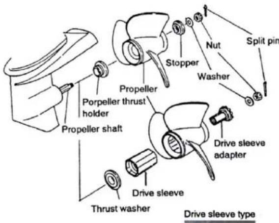
Replacing the propeller.
A worn or bent propeller will affect engine performance and may over time cause engine trouble.
- Pull out the split pin and remove the propeller nut and washer,
- Remove the propeller by pulling towards you.
- Apply grease to the propeller shaft before mounting the new propeller.
- Fit the washer, securely tighten the nut and insert the split pin.
text_image
Propeller shaft Porpeller thrust holder Propeller Stopper Nut Washer Split pin Drive sleeve adapter Drive sleeve Thrust washer Drive sleeve type3. Raider Running
a. Fuels (Multi-fuel)
The Raider can run on jet fuels (JP-5/8), diesel fuel, kerosene, gasoline or gasohol/ethanol. There is no knob or valves to turn. If you switch from one fuel to another fuel the Raider engine will operate during transition. When using the twin engine configuration it is recommended similar fuels are used.
b. Raider Break in
10 Hours. The Raider has provided the break in at the factory. The most critical time in the life of the Raider engine is the first 10 hours of operation. Correct operation during this break-in period will prolong the life of the engine and ensure optimum performance. The procedures we follow are shown below.
| Time | Break-in method | Running Conditions |
| 0 min- | Trolling or idling speed | Cruising at minimum speed |
| 10 min- | Throttle opening < 1/2about 3,000 rpm | - |
| 1 hr- | Throttle opening < 3/4about 4,000 rpm | Run with full throttlefor 1min-10 min. |
| 2 hrs- | Throttle opening 3/4about 4,000 rpm | Run with full throttlefor short time |
| 10 hs- | Normal running | - |
c. Normal Starting Procedure
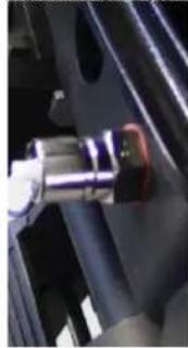
Move the tilt/run lever to RUN position. Place engine in normal operating position. Connect the fuel line connector from the tank to the engine's fuel connector. Turn fuel line connector onto fuel tank connector. . = If the fuel tank has a manual vent, open it. If you don't, the engine will eventually die from fuel staryation. Squeeze fuel line primer bulb until firm.
natural_image
Close-up of a mechanical component with metallic parts and a red accent, mounted on a dark metal frame (no visible text or symbols)Raider Fuel valve

text_image
Engine side Fuel tank side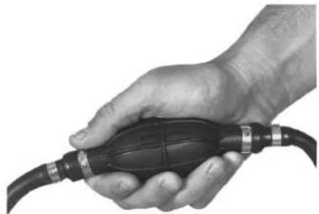
natural_image
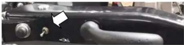
Close-up of a hand holding a black automotive fuel plug with coiled cable (no text or symbols visible)! Attach the clip and lanyard assembly to emergency stop switch. Clip must be installed to start engine. Attach lanyard to secure place on your clothing. An extra emergency restart clip is provided and stored in the cowling. Turn twist grip to full closed throttle position. = Move the twist grip from the start position. Move shift lever to the NEUTRAL position. The engine will ONLY start in NEUTRAL.
Pull starter handle slowly until starter engages, then pull forcibly for a full rope pull (short or slow pulls will not provide enough current to the ECU to start). Maintain fuel pressure by squeezing primer bulb until engine is running. Raider comes with an electric start option. Flip on switch; press start button.
natural_image
Close-up of a black mechanical component with a white arrow pointing to a small feature (no visible text or symbols)d. After Raider Starts/Warm Up
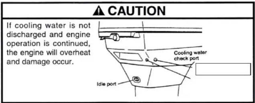
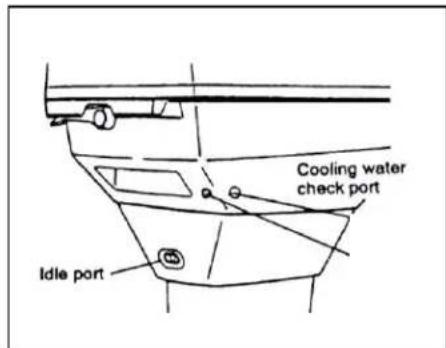
α Check the water pump indicator. A steady stream of water indicates the water pump is working.
= IF the water pump indicator is not discharging a steady stream of water, STOP the engine when it is safe
text_image
▲ CAUTION If cooling water is not discharged and engine operation is continued, the engine will overheat and damage occur. Cooling water check port Idle porte. Forced engine oil feeding
When the engine is new or has been left without operation for a long time execute the following operation for forcedly feeding the engine oil to the oil line before starting the Raider Engine.
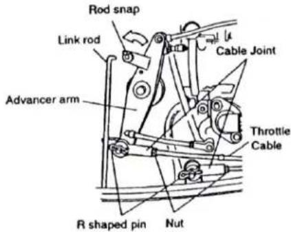
- Disconnect the link rod by turning the rod snap interlocking with the oil pump as shown in the figure.
- Make sure the oil pump control lever is set at open side position.
- Idle the engine for more than 30 minutes.
- Reset the link rod to the advancer arm.
f. Idle Speed
= Idle speed is controlled by the ECU and is not adjustable.
text_image
Rod snap Link rod Advancer arm Cable Joint Throttle Cable R shaped pin Nut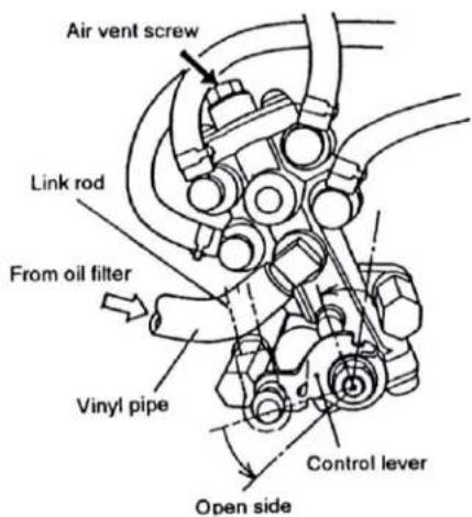
text_image
Air vent screw Link rod From oil filter Vinyl pipe Control lever Open sideg. Throttle Friction
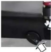
β To increase throttle friction, turn the throttle friction screw clockwise. To decrease friction, turn the throttle friction screw counterclockwise. DO NOT over tighten.
natural_image
Close-up of a black mechanical component with a circular knob and red handle (no visible text or symbols)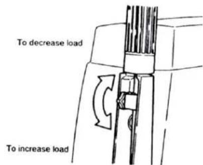
text_image
To decrease load To increase loadh. Shifting
= To avoid gear case damage:
DO NOT attempt to shift engine from NEUTRAL to FORWARD or REVERSE when the engine is NOT running. Clutch dogs can align lug-on-lug and result in shift linkage and lower gear case parts damage. When shifting, always wait until boat has slowed and engine is at idle speed.
Shift to FORWARD
After engine is running smoothly, turn throttle control to SHIFT position or slower. Move shift lever to FORWARD/down with a firm, quick motion. DO NOT shift engine with throttle control advanced beyond the shift position.
natural_image
Close-up of a black mechanical component with a handle and two circular ports, no visible text or symbols.- Increase Speed: Turn throttle control counterclockwise toward FAST (toward you if seated in boat next to engine).
- Decrease Speed: Turn throttle control clockwise toward SLOW (away from you if seated in boat next to engine).
Shift to NEUTRAL
Turn throttle control clockwise to the SHIFT position or slower. Move the shift lever to NEU-TRAL with a firm, quick motion.
= When shifting, always wait until boat has slowed and engine is at idle speed.
Shift to REVERSE
Turn throttle control clockwise to the SHIFT position or slower. Move shift lever to REVERSE with a firm, quick motion.
= When in REVERSE, operate with additional care as the engine has no impact protection if it hits an underwater obstruction.
!Do not operate engine in REVERSE with the tilt/run lever in TILT. Engine may tilt out of the water, resulting in loss of control.
i. Stopping Raider
- Slow engine to idle speed.
- Move shift lever to NEUTRAL position.
- Press and hold stop button until the engine stops running.
j. Trim Angle
flowchart
graph TD
    A["Start: Boat with fish and water symbol"] --> B["Step 1: Arrow on boat"]
    B --> C["Step 2: Sailboat on water symbol"]
    C --> D["Step 3: Boat on boat with fish and water symbol"]
    D --> E["End: Arrow on boat with fish and water symbol"]
    style A fill:#fff,stroke:#000
    style B fill:#fff,stroke:#000
    style C fill:#fff,stroke:#000
    style D fill:#fff,stroke:#000
    style E fill:#fff,stroke:#000
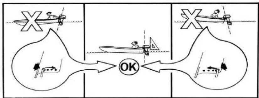
Engine should be perpendicular to water when boat is underway. This adjustment can only be determined by water testing the boat. Set angle adjustment for NORMAL boat load.
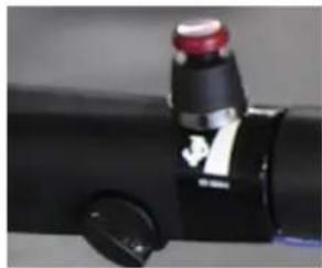
Move angle adjusting stop rod as shown in picture.
natural_image
Close-up of a black cylindrical device with red and white adjustment knobs, no visible text or symbols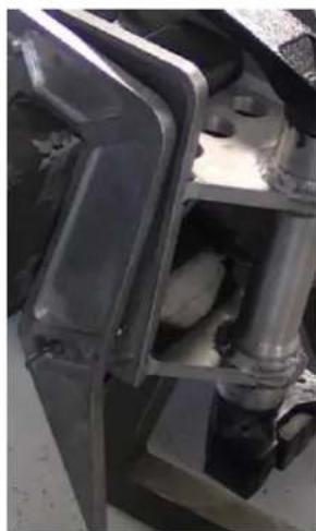
natural_image
Close-up of mechanical components with no visible text or symbolsk. Trailering
Place the engine in the normal vertical position. For additional road clearance, move angle adjusting rod to an outer stern bracket position. Refer to Raider Trim Angle.
= DO NOT use the tilt support as a Trailering bracket. The engine should always be resting on the angle adjusting stop rod when under full power or when trailering.
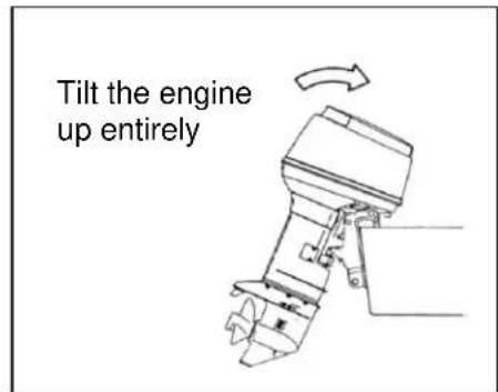
I. Tilting
= DO NOT push down on tiller handle to tilt engine.
Raise Raider
- Move tilt/run lever to the TILT position.
- Use tilt grip on engine cover to raise engine. When desired angle
is reached, move lever to lock position.
text_image
Tilt the engine up entirely! Lower Raider
- Move tilt/run lever to RUN position. Engine will lower to set run position.
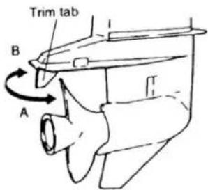
m. Trim Tab Adjustment
Trim Tab Adjustment
If straight-line cruising can not be achieved, adjust the trim tab located under the anti-ventilation plate.
■ If the boat veers toward the right, direct the trim tab towards A.
■ If the boat veers toward the left, direct the trim tab towards B.
text_image
Trim tab B ANotes:
- The trim tab also acts as an anode to prevent electrolytic corrosion. Therefore do not paint or grease this part.
- After adjustment securely tighten the trim tab fixing bolt.
- Check for looseness of the bolt and the trim tab at regular intervals. Due to corrosion, the trim tab will wear down over time.
n. Shallow Water Drive
The engines shallow water tilt is controlled by the gas assist tilt cylinder
Engage Shallow Water Drive
- Move red button tilt/run lever to TILT position
- Raise the engine to the desired shallow drive position.
- When drive angle is reached, lock position.
Disengage Shallow Water Drive
- Move red button tilt/run lever to RUN position.

natural_image
Close-up of a mechanical device with a red component inserted, showing internal components and no visible text or symbols.o. Shallow Water Operation
= DO NOT operate engine with gear case dragging on sea bottom. This can result in propeller or water pump damage.
- Place engine in shallow water drive position. Refer to Shallow Water Drive.
a. !DO NOT operate engine in REVERSE with the tilt/run lever in the TILT position. Engine can tilt up resulting in loss of control.
- Run at SLOW SPEEDS ONLY. Check water pump indicator often. (Note; Shallow water drive setting can be adjusted for different boat load conditions.)
- Before operating in deep water, be sure to lower engine and move tilt/run lever to the RUN position.
! Engine does not have impact protection when operated in the shallow water drive position or when the tilt/run lever is in the TILT position. Engine will tilt up suddenly if it hits an underwater obstruction.
natural_image
Close-up of a small electronic device with a grid and arrow indicator (no visible text or symbols)p. Impact Damage
Your boat and engine can be seriously damaged by a collision at high or low speeds, while trailering, or in the water.
If you hit an object, stop immediately and examine the engine for loose mounting hardware or clamp screws. Inspect for damage to stern and swivel brackets, and components in the area of impact. Also, examine the boat for damage. Tighten any loose hardware. If collision occurred in the water, proceed slowly to shore. Before operating again, inspect all components.
! Failure to inspect for damage can result in sudden, unexpected component failure and loss of boat control. Uncorrected damage can adversely affect the boat and engine's ability to resist subsequent collisions.
q. Special Operating Conditions
Sea Water
Fresh water flushing is recommended after use in salt, polluted, or brackish water to prevent deposits from clogging the cooling passages.
Check gear case anodes for deterioration, and replace if necessary.
During long periods of non-use, tilt engine so that the gear case is out of the water, unless the temperature is below 32^ F ( 0^ C). When removing engine from water, allow cooling system to drain completely by placing engine in upright position.
Weedy Water
Weeds can block the water intakes and cause engine to overheat. Weeds on the propeller will cause engine to vibrate.
Run at slow speeds and reverse engine frequently to clear weeds from propeller. Check water pump indicator often. Remove weeds from propeller and water intakes before operating in clear water.
Freezing Weather
To avoid engine damage, keep the gear case submerged in the water at all times. Before operating in freezing temperatures, check gear case lubricant. If leakage is found, gear case seals will need service.
When removing engine from water, keep the engine in an upright position until the cooling system is completely drained.
= Water that leaks into gear case or is left in the cooling system can freeze when the engine is removed from the water. This can cause serious damage.
r. Overheating
= DO NOT operate engine out of water even momentarily.
The engine's Water Temperature sensor is NOT a warning device.
The Raider does not have an overheat warning. The Raider will not initiate a warning to prevent powerhead damage. The EMM will only monitor and store a code in the event of an overheat.
If you suspect the engine is overheating or has overheated, STOP the engine only when it is safe.
When operating the engine, the water intakes must be completely submerged. Make sure the water intake screens are not installed upside down (ramps must be forward). If upside down, the engine will overheat. Observe proper transom height and engine trim angle.
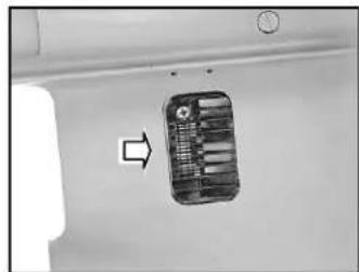
When engine is running, the water pump indicator on the star-board side of the lower motor cover must be discharging a steady stream of water. Check the indicator often, particularly when operating in weeds, mud, or debris laden water, or at an extreme engine angle.
text_image
Cooling water check port Idle portIF the water pump indicator stops or becomes intermittent, reduce engine speed to an idle when it is safe. Shift engine into REVERSE and operate at a slow speed for about 10 seconds. This might clear debris blocking the water intake screens.
IF the water pump indicator is still not discharging a steady stream of water, SHUT OFF the engine when it is safe. Clean the water intake screens and water pump indicator. Restart the engine and run at idle.
IF the water pump indicator still does not discharge a steady stream of water, SHUT OFF the engine when it is safe. DO NOT attempt to operate engine.
IF a steady stream of water is visible from the water pump indicator, check to see if the restrictor is installed in the end of the water hose. Without it, the engine and ECU will overheat. Continue to run engine at SLOW SPEED ONLY when it is safe until it returns to normal operating temperature.
= If the engine overheats; the cylinder and exhaust cover screws must be re-torqued.
s. Emergency Starting
! Make sure the shift lever is at NEUTRAL to prevent sudden boat movement when the engine starts.
! The engine cover is a machinery guard. Prevent injury by keeping hands, clothing, and hair clear of all moving parts. DO NOT use your hands to turn the flywheel; use recoil starter only.
! Prevent electric shock by keeping clear of the ignition coil and spark plug leads when the engine is being started or is running. Shock can cause serious personal injury under certain conditions.
natural_image
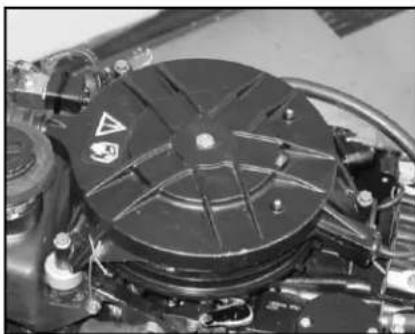
Close-up of a mechanical component with a circular black lid and warning symbol (no readable text or labels)Unlatch, then lift and remove engine cover.
Reach inside the cowling cover. On one side you will find a rope with handle; on the other side of the cowling you will find a tool that allows the removal of the pull starter.
Use the special service tool to remove the three screws retaining the starter housing.
Lift the pull starter assembly from engine.
Take stored starter rope and wind on the engine flywheel with the knot end in the grove.
natural_image
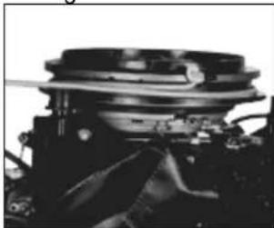
Close-up of a mechanical component with layered structure and mounting bracket (no visible text or symbols)If starter cord is missing or gets broken, it might not be long enough to use as an emergency starter cord. If in you need an additional rope cut cord from starter assembly.
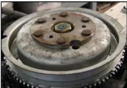
Tie a knot to one end of cord. Place knot in the notch on top of flywheel. Wrap cord around flywheel clockwise as shown. Follow Normal Starting Procedure.
! DO NOT attempt to replace starter assembly or engine cover while engine is running.
t. Pre-Submersion Procedure
To prevent water intrusion on electronics during submersion:
- Make sure the inside of all electrical connectors are thoroughly connected.
- Insure the de-watering valves at the back, mid and front of the Raider is working correctly by turning valves to closed position.
- Any time the ECU or other connectors are removed, insure they are re-connected correctly.
-
Insure oil tank if fully filled and cap tightened.
-
Connect fuel line and pump primer bulb until firm resistance is felt to fill fuel system.
natural_image
Close-up of a mechanical gear assembly with central hub and bolt holes (no visible text or symbols)u. Dewater Procedure
- Connect the fuel line connector from the tank to the engine's fuel connector.
- Make sure that the shift lever is in the NEUTRAL position.
- Turn twist grip to the full open throttle position.
- Turn the 3 drain valve levers to the DRAIN position. (1/4 turn counterclockwise)
- Move tilt/run lever to the TILT position.
-
Tilt engine to full tilt position. Move tilt/run lever to lock position.
-
!To avoid engine falling during dewater procedure; tilt/run lever MUST remain in the LOCK position.
-
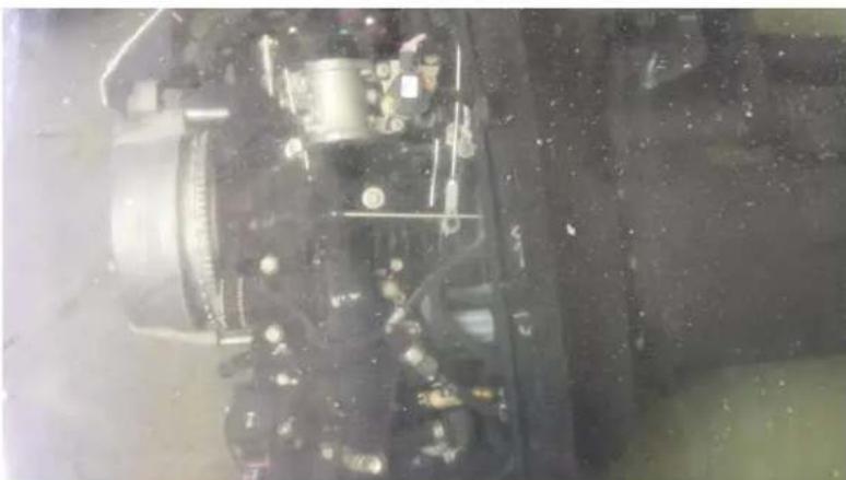
Allow crankcase to drain for 2 minutes. During this time, connect the fuel line and pump the primer bulb to flush out any water that may have entered the fuel system. Pull crank rope slowly.
-
Lower engine to run position. Move tilt/run lever to lock position, Open throttle to wide open position.
-
With all 3 drain valves still open pull recoil starter 10 times to dry out crankcase and combustion chamber.
natural_image
Underwater view of a vehicle's internal engine compartment with visible motors and wiring (no text or symbols)Starting After Submersion
-
Move all 3 drain valves to the run position.
-
Pump primer bulb until firm resistance is felt.
-
Pull starter handle slowly until starter engages, then pull forcibly to start.
-
Run engine at part throttle for 10-15 seconds.
= You MUST run the engine after performing the Dewater Procedure to dissipate internal moisture. In other than mission situations, run engine under normal operating conditions for 15 to 40 minutes.
During mission situations, operate as conditions require.
v. Post Submersion Procedure
After your mission, the Raider must be prepared to be returned to nonuse or prepared for your next mission.
If the RAIDER is re-submersed after your mission and it cannot be serviced, keep it submersed to avoid prolonged exposure to the atmosphere, until it can be serviced. If the Raider is brought on deck and it can't be operated or serviced, keep it submerse in fresh water, but get it prepared for your next mission as soon as possible.
If the RAIDER can be operated on deck, dewater the engine following the procedures in De-water Procedure; operate the engine for approximately five minutes at full operating temperature with fresh water. Remove the upper cover to allow the powerhead and other components to air dry. Whenever possible after use or submersion in sea water, wash entire engine with fresh water to remove salt deposits and wipe down with a dry cloth. Spray the entire powerhead with an Anti-Corrosion Spray/penetrant/lubricant or equivalent. Follow this procedure to prepare the Raider for your next mission.
4. General Maintenance
! General Safety Warnings
When replacement parts are required, use genuine
Raider parts or parts with equivalent characteristics including type, strength, and material. Failure to do so may result in product malfunction and possible injury to the operator and/or passengers.
To prevent possible eye injury, always wear SAFETY GLASSES while servicing the unit.
Always read and follow safety related precautions found on containers of hazardous substances like parts cleaners, primers, sealants, and sealant remover.
The engine cover is a machinery guard. Use caution when conducting tests on running engines. Do not wear jewelry or loose clothing. Keep hair, hands, and clothing away from rotating flywheel.
Replace any locking fastener (locknut or patch screw) if it's locking feature becomes weak. Definite resistance to tightening must be felt or locking fastener is not suitable for continued use. Replace only with authorized replacement part or equivalent.
a. Fuel/Oil Requirements
ECU controlled oil pump with an engine mounted oil reservoir.
Oil Requirements:
Above 30° F Biodegradable Outboard Oil
Below 30° F 100% Fully Synthetic 2-Cycle Engine Oil
Oil Tank Capacity 56 oz. (1,66 liters)
Recommended Oil
Above 30° F: Biodegradable Outboard Oil
Below 30° F: 100% Fully Synthetic 2-Cycle Engine Oil
Recommended Fuel: Preferred fuel: Jet A, JP5 or JP8 jet fuel, kerosene
Alternate fuel: Diesel DFM-F76, Biodiesel 20, 30, gasoline
! Fuel leakage can contribute to a fire or explosion.
b. Removing and Carrying the Raider
(1) Removing the motor
① Stop the engine.
② Disconnect the fuel connector, the remote control cable bra
③ Remove the motor from the hull and completely drain the water from the gear case.
(2) Carrying the motor
Be sure to keep the engine vertical whenever you carry the motor.
natural_image
Line drawing of a manual oil pump or milling machine with a propeller and handle (no text or symbols)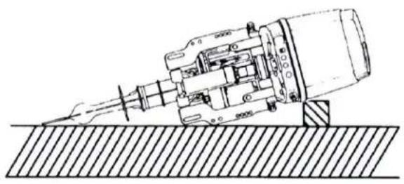
natural_image
Technical line drawing of a mechanical assembly or tool with no visible text or symbolsc. Tool Kit and spare parts
| Name | Remark | ||
| Servicing Tools | Tool Bag | 1 | |
| Socket Wrench (16mm) | 1 | ||
| Socket Wrench (10 x 13) | 1 | ||
| Socket Wrench Handle | 1 | ||
| Pliers | 1 | ||
| Screwdriver (Phillips-type and flat head) | 1 | Adapter-type | |
d. Corrosion Protection
Whenever possible after use in sea water or submersion in sea water, wash entire engine with fresh water to remove salt deposits and wipe down with a dry cloth. Spray entire powerhead with a liberal coat of Anti-Corrosion Spray penetrant/lubricant or equivalent.
Though not specifically mentioned as a service procedure, Anti-Corrosion Spray or equivalent should be applied after any service repairs under the engine cover and repeated at regular intervals to protect powerhead components. Anti-Corrosion Spray leaves a thin, non-messy, transparent film that actually lifts water and moisture from metal surfaces. It protects equipment and tools that are left outdoors, even in humid coastal areas. Anti-Corrosion Spray dries out ignition systems to start wet engines and stops moisture-induced short circuits in electrical systems.
e. Optional Accessories
1) Both the 50 and 40 Horsepower can be purchased with a battery system that is enclosed under the cowling. This battery is safe underwater; can be recharged by the Raider motor once the motor is started.
2) Both the 50 and 40 Horsepower can be fitted with a dual motor single operator assembly that can quickly be attached to twin motors for a single operation. The motors come with a preset in each tiller arm and an assembly to control the throttle with a remote cable that attaches to the second motor. This controls throttle for both engines.
f. Trouble shooting
| Difficult to start engine | Engine runs erratically | Boat speed loss | --- | Possible Causes | ||
| ● | Empty fuel tank | |||||
| ● | ● | Incorrect connection of fuel system | ||||
| ● | ● | Air enters fuel line | ||||
| ● | ● | Deformed or damaged fuel pipe | ||||
| ● | Closed air vent on fuel tank cap | |||||
| ● | ● | Fuel filter/fuel pump is clogged with dust. | ||||
| ● | Use of improper fuel | |||||
| ● | Incomplete forced fuel feeding by primer bulb | |||||
| ● | ● | Poor connection in compression system | ||||
| ● | ● | Use of non-specified spark plugs | ||||
| ● | ● | Dirt or carbon deposits on spark plugs | ||||
| ● | ● | No sparking or poor sparking (Failure in component of ignition system) | ||||
| ● | Insufficient cooling water flow | |||||
g. Storage
Use the following procedure to properly prepare the engine for extended periods of nonuse. These steps are intended to protect the engine during storage and simplify the out of storage servicing procedure.
= Use a flushing attachment to prevent engine or water pump damage if you operate the engine on a trailer or dolly.
! When using a flushing attachment, always remove engine's propeller before starting engine to prevent accidental contact with moving propeller.
-
Follow the directions on a can of Storage Fogging Oil and spray oil through the throttle plate.
-
Stop engine and remove all spark plugs. Spray Storage Fogging Oil into the spark plug holes.
-
Pull starter to distribute the fogging oil throughout the cylinders. Install and torque the spark plugs.
! Leave spark plug leads disconnected to prevent accidental starting during storage.
-
If the engine is removed from the boat, examine all hardware you loosened or removed. Replace damaged or missing parts with genuine Raider parts or equivalent. These fasteners are made of special materials to resist weakening and rusting. Do not substitute these fasteners with nuts and bolts which look the same. Using the wrong nuts and bolts may result in sudden, unexpected loss of engine control.
-
Inspect the engine's steering, throttle, de-watering and shift systems for damage due to corrosion, aging, lack of maintenance, or abuse. Follow the maintenance and lubrication recommendations when servicing these systems.
- Replace the engine's fuel filter.
- Clean and inspect oil reservoir. Fill the oil tank with recommended oil to reduce or prevent condensation from forming in the tank during storage. Tank should be full prior to submersion.
- Remove propeller and check for damage. A slightly bent propeller blade can hardly be noticed but will affect the performance of the engine. Clean the propeller shaft and lubricate with grease.
- Drain and refill the gear case. Lubricate the engine. See Gear case Lubrication in this section.
- Check the engine carefully. Make sure screws and nuts are tight. Replace damaged or worn parts.
- Make sure electrical and fuel system fasteners and clamps are tight and in good condition. Failure to do so may cause electrical sparks and fuel leakage under the engine cover. Fire and explosion could occur.
- Replace engine cover. Use touch-up paint where needed.
- Coat all outside painted surfaces of engine with automotive wax.
- The engine must be stored in a normal (vertical) position on the boat or on an adequate engine stand.
h. Out of Storage Service
-
Check gear case lubrication. If leakage is evident, gear case seals may need attention. See Gear case Lubrication in this section.
-
Apply a light coating of Electrical Grease to the ribbed portion of the spark plug ceramics and the opening of the spark plug covers. Connect spark plug leads. Make sure spark plug boots are not cracked or torn.
-
When engine is reattached to the boat's transom, make sure the mounting brackets, clamps, and hardware are structurally sound and in proper working condition. If mounting components use the wrong fasteners, are carelessly installed, or are defective, sudden unexpected loss of engine and boat control may result.
-
Check for evidence of water in the oil tank. Do not operate the engine if water is present in the oil tank. Serious powerhead damage can occur.
-
If the fuel hose has been disconnected, reinstall it.
i. After Submersion
After submersion or after a mission, the Raider must be prepared to be returned to nonuse or prepared for your next mission.
If the Raider is re-submersed after your mission and it cannot be serviced, keep it submersed until it can be serviced to avoid prolonged exposure to the atmosphere. If the Raider is brought on deck and it can't be operated or serviced, keep it submerse in fresh water, but get it prepared for your next mission as soon as possible.
If the Raider can be operated on deck. Follow these procedures to prepare the Raider for your next mission.
- Dewater the engine following the procedures in Dewater Procedure.
- Operate the engine for approximately five minutes at full operating temperature with fresh water.
- Whenever possible after use or submersion in sea water, wash entire engine and powerhead with fresh water to remove salt deposits, especially under the flywheel where the accumulation of deposits will build up. Wipe down with a dry cloth.
- Spray the entire powerhead with a liberal coat of Anti-Corrosion Spray penetrant/lubricant or equivalent. Spray 6 & 1 Penetrating Lubricant or equivalent under the flywheel.
- Leave the upper cover off, when possible to allow the powerhead and other components to air dry.
Serial Numbers on Raider:
Can be found on each transom mount for identification.
text_image
PMFS 004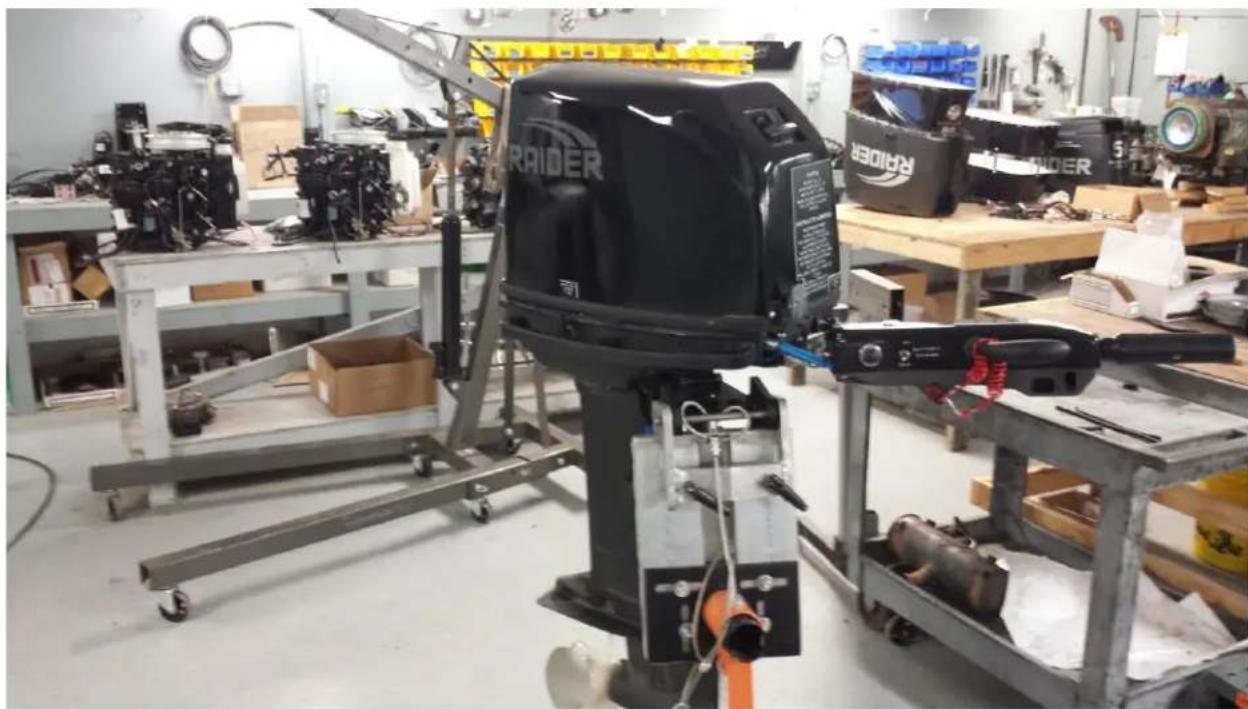
natural_image
Interior of a workshop with a black ROIDER robotic arm and mechanical components on metal racks (no visible text or symbols)Motor on Stand
text_image
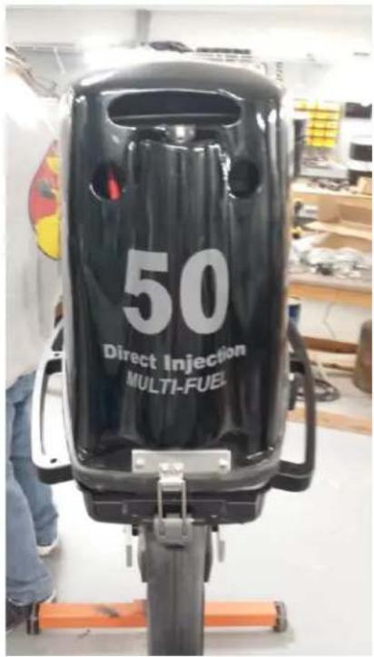
50 Direct Injection MULTI-FUELBack of Raider
text_image
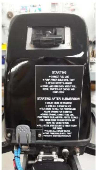
STARTING • CONNECT FUEL LINE • PUMP PRIMER BULB UNTL TIGHT • ATTACH SAFETY LAYERD • STAND AND USB BODY WEIGHT PULL RECOIL STARTER OUT QUILLY AND COMPLETEX STARTING AFTER SUBMERSION • MOUNT DRIVE ON TRANSOM • OPEN ALL 3 STRAM VALVES • TILT DRIVE TO RALL TILT POSITION AND ALLOW DRAMING FOR 2 STRATES. • CURRY DRAMING, CONNECT TIEL LINE, PUMP PRIMER BULB, AND PULL RECOIL, BLOWLE • TILT DRIVE DOWN TO RUB POSITION AND MOVE TILT LEVER TO RAIL • PULL RECOIL STARTER OUT TO TIMES TO DRY OUT ENGINE • CLOSE ALL 3 STRAM VALVES • PUMP PRIMER BULB UNTL TIGHT • EXCUTE STARTING PROCEDUREFront of Raider

text_image
COMBUSTION CHAMBER ← DRAIN ↑ RUNTop view of rear dewatering valve
Raider Advantages
• Best Power to Weight Ratio
- Long history of bullet proof reliability and maintenance
- Most compact in horsepower class
- Extensive modifications to commercial off the shelf outboard solely for the warfighters needs
- No bells and whistles
○ Rugged
○ Durable
• Originally designed for Japanese fisherman to work day in and day out
- World-wide parts availability results in life cycle cost savings
- Most parts for the Raider 50 are common to the Raider 40
RAIDER
Robotics and Conceptual Engineering, Inc.
2702 Lake Dauterive Rd.
Loreauville, LA 70552
(337) 577-6810
7887 Bryan Dairy Rd
Largo, FL 33777
(321) 403-3585