AV2110DN - Security Camera Arecont Vision - Free user manual and instructions
Find the device manual for free AV2110DN Arecont Vision in PDF.


User questions about AV2110DN Arecont Vision
0 question about this device. Answer the ones you know or ask your own.
Ask a new question about this device
Download the instructions for your Security Camera in PDF format for free! Find your manual AV2110DN - Arecont Vision and take your electronic device back in hand. On this page are published all the documents necessary for the use of your device. AV2110DN by Arecont Vision.
USER MANUAL AV2110DN Arecont Vision
natural_image
Close-up of a black optical lens mounted on a beige cylindrical base (no visible text or symbols)MegaVideo® Compact Camera Installation Manual

Arecont Vision
megapixel technology... beyond imagination
MegaVideo® Compact Camera Installation Manual
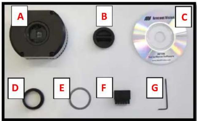
Inside the box:
A. MegaVideo ^® compact camera
B. Rubber gasket (preinstall on the camera)
C. CD with AV100 software and user manuals (license key required for recording)
D. C to CS lens adapter
E. 0.5mm lens spacer ring
F. 6-position external power & IO plug
G. 0.05" hex L-Key
text_image
A B C D E F GImage 1
Camera Power Up:
- Remove the camera and hardware from the box
- Attach the camera to the mounting bracket.
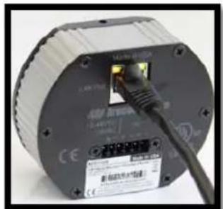
- Connect the MegaVideo ^® Compact Camera to a PoE port on 100Mbps network PoE switch using an Ethernet cable as shown in Image 2, if using a PoE solution.
natural_image
Close-up of a cylindrical electronic device with a black cable inserted into the top section, showing internal components and no visible text or symbols.Image 2
- Connect the PoE switch to your computer's network port using an Ethernet cable. If the camera will be powered via PoE, please skip to step 5.
NOTE: A yellow LED on the rear of the camera will turn on after a few seconds.
a. The flashing yellow LED indicates that a link to your computer has been established.
b. A green LED will blink when the camera has been accessed.
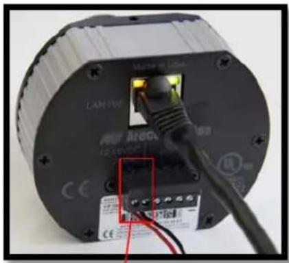
- If the camera is powered by an outside power supply, connect the power wires to the appropriate contacts of the 6-position connector using a small flathead screwdriver and connect the 6-position plug to the camera as shown in Image 3-1.
Arecont Vision MegaVideo® Compact Camera Series Installation Manual
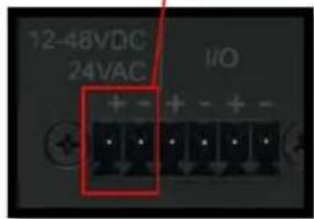
NOTE 1: Ensure that the polarity of the DC input on the camera matches the way that wires are installed in the connector shown in Image 3-2.
NOTE 2: AC power does not have polarity.
natural_image
Close-up of an electrical component with a black housing and wiring, no visible text or symbolsImage 3-1
text_image
12-48VDC 24VAC I/O + - + - + - + - + - + -Image 3-2
Camera Installation:
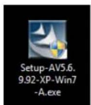
- Install the AV100 application manager software as shown in Image 4. (found on the CD)
- Run the AV100 application manager by double clicking on the icon as shown in Image 5. (found on your desktop)
text_image
Setup-AV5.6, 9.92-XP-Win7 -A.exeImage 4
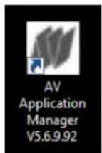
Image 5
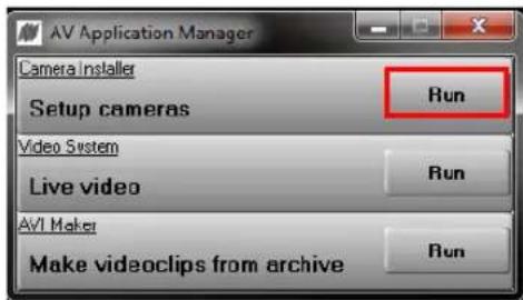
- Select "Run" next to "Setup Cameras" from the AV100 application manager as shown in Image 6 and wait for "Arecont Vision Camera Installer" window to appear as shown in Image 7.
text_image
AV Application Manager Camera Installer Setup cameras Run Video System Live video Run AVI Maker Make videoclips from archive RunImage 6
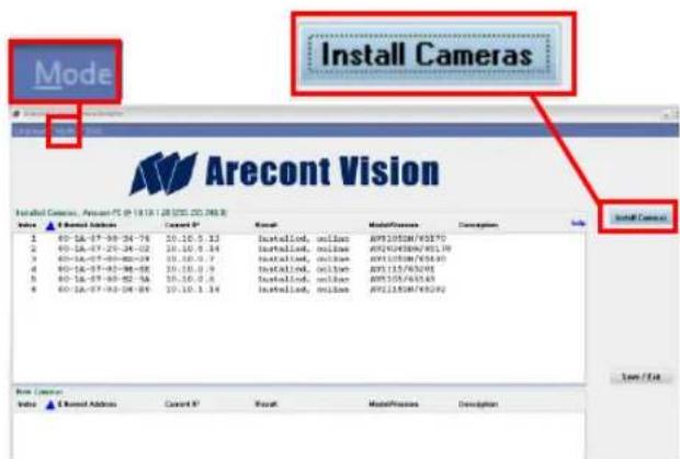
- Click "Mode" tab to select desired install mode on the Arecont Vision Camera Installer as shown in Image 7.
NOTE 1: Basic Mode (default setting): software will automatically discover and change / assign IP address to match PC subnet.
NOTE 2: Advanced Mode: software will automatically discover but allow manual update of the IP address. See "AV100 Installation Manual" (found on the CD) for details on Advanced Mode.
text_image
Mode Install Cameras Arecont Vision Installed Camera, Amount PS @ 18.18.128 (ISO: CD:246.8) Install Camera File Edit Options Next Print ModelProcess Description Help Install Camera 1 60-1A-07-09-24-76 10.10.5.13 Installod, online APX105DM/60170 2 60-1A-07-20-24-02 10.10.5.14 Installod, online APX102DM/60170 3 60-1A-07-09-02-03 10.10.5.7 Installod, online APX105DM/60180 4 60-1A-07-02-08-08 10.10.5.9 Installod, online APX115/60201 5 60-1A-07-03-02-16 10.10.5.4 Installod, online APX155/60249 6 60-1A-07-03-04-04 10.10.5.14 Installod, online APX115DM/60292 Book Creation Value Install Address Next Print ModelProcess Description Help Use / ExitImage 7
- Select "Install Cameras" on the Arecont Vision Camera Installer as shown in Image 7.
- Confirm all cameras connected to the network switch appear in the upper window.
- Repeat Step 10 if all of the cameras do not appear in the upper window.
CAUTION: If the software does not find a camera, the software utility may be blocked by the anti-virus or Windows® firewall. Before turning them off, please consult your IT manager.
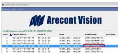
NOTE : Double click the camera model on the Camera Installer as shown in Image 8 to access the camera web interface. See "AV Camera Web Page User Manual" (found on the CD) for details on the web interface.
text_image
Arecont Vision Installed command, Available: TC-01.18.1.29 (205.25.248.8) Index ▲ ArchiveAddress CameraIP Install MakeVision Description 1 00-la-97-09-24-76 10.11.5.13 installed, online AV2155/05/5519 2 00-la-97-09-24-92 10.11.5.14 installed, online AV2155/05/6519 3 00-la-97-05-05-29 10.11.6.7 installed, online AV2155/05/6519 4 00-la-97-02-06-16 10.11.6.8 installed, online AV2155/05/6519 5 00-la-97-02-82-9A 10.11.6.6 installed, online AV2155/05/6519 6 00-la-97-03-06-86 10.11.1.14 installed, online AV2155/05/6520Image 8
- When all cameras appear, select "Save/Exit." The AV100 application manager will appear.
- From the "AV100 Application Manager" menu, select "Run" to view live images.
NOTE : See "AV100 Installation Manual" (found on the CD) for details on camera configurations.
Camera Focus:
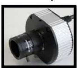
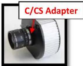
- Install the C/CS lens adapter ring for a C mount lens. If unable to properly focus, add the 0.5mm spacer before attempting to adjust the back focus.
NOTE: All MPL series lenses except MPL6.0 are CS mount and do not require the C/CS lens adapter ring to focus the camera as shown in Image 9.
natural_image
Close-up of a mechanical component with a cylindrical body and threaded shaft (no visible text or symbols)Image 9
text_image
C/CS AdapterImage 10
Arecont Vision MegaVideo® Compact Camera Series Installation Manual
NOTE: The Ultra HD Lens series is C mount and will require the C/CS lens adapter ring in order to adjust the back focus as shown in Image 10.
- Loosen the set screws on the lens.
- Fully open the lens iris aperture.
- Focus the camera lens (Skip Step 19-21 if correctly focused).
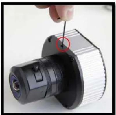
- If needed, adjust the back focus by using the provided Hex L-Key, loosen the set screws on the top and bottom of the camera, adjust back the focus as shown in Image 11.
NOTE: Some lenses will require back focus adjustment in order to properly focus the camera.
natural_image
Close-up of a mechanical component with a hand adjusting a bolt, showing internal structure and mounting features (no text or symbols visible)Image 11
- Focus the camera again.
-
Secure the camera back focus ring with the set screws.
-
Close the lens aperture as necessary to obtain depth of field.
- Tighten the set screws on the lens.
NOTE: For more information on proper focusing technique, please watch the "Focusing Arecont Vision Megapixel Cameras" Best Practices Training Video at http://www.arecontvision.com/trainingvideo.php
Auto Iris Camera: (-AI models only)
- Connect DC auto iris lens cable to the camera as shown in Image 12 and Image 13.
- Repeat Step 14-22 to focus the camera.

natural_image
Close-up of a mechanical device with a black cable and labeled component (no readable text or symbols)Image 13
MegaVideo® Compact Camera I/O Cable Connection
Required Tools:
- Flathead screwdriver
text_image
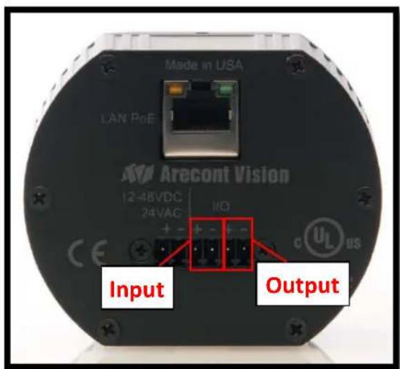
Made in USA LAN PoE Arecont Vision 12-48VDC 24VAC I/O CE + - + - Output Input c UL usImage 14
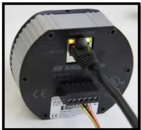
- To use the I/O ports of the MegaVideo® Compact Camera, insert the connector into the camera and locate the "I/O" ports as shown in Image 14. NOTE: There are six connectors that look identical, be sure to use the correct I/O ports as shown in Image 15.
natural_image
Close-up of a black cylindrical electronic device with a cable inserted, showing internal components and wiring (no readable text or symbols)Image 15
| Electrical Characteristics: | Min | Max | |
| Input voltage (V)(measured between + and - terminals) | ON | 2.9 | 6.3 |
| OFF | 0 1.3 | ||
| Output current (mA)(measured between + and - terminals)Applied Voltage Rage: 0 - 80V | ON | - | 50 |
| OFF | - 0.1 | ||
Table 1
NOTE: Both the input and the output are electrically isolated from the rest of the camera's electrical circuitry via general-purpose photo couplers. The input is additionally protected with a serial 250 Ohm resistor and a debouncing circuit. Duration of any input signal should be at least 5ms to comply with the requirements of the debouncing circuit.
Leading
the way in
Megapixel
video
Arecont Vision
425 E. Colorado Street, 7th Floor
Glendale, CA 91205
support@arecontvision.com
www.arecontvision.com
+1.818.937.0700
877.CAMERA.8

Arecont Vision
megapixel technology...
beyond imagination