AT-800 - Wall mount YAMAHA - Free user manual and instructions
Find the device manual for free AT-800 YAMAHA in PDF.

| Product Type | Wall Mount |
| Brand | Yamaha |
| Model | AT-800 |
| Compatible Devices | Flat-panel TVs up to 80 inches |
| VESA Compatibility | 100x100mm to 600x400mm |
| Maximum Weight Capacity | 50 kg (110 lbs) |
| Material | Heavy-duty steel |
| Finish | Black powder coat |
| Dimensions (WxHxD) | 700 x 400 x 50 mm (27.6 x 15.7 x 2.0 inches) |
| Weight | 3.5 kg (7.7 lbs) |
| Wall Plate Size | 650 x 180 mm (25.6 x 7.1 inches) |
| Installation Type | Fixed wall mount |
| Level Adjustment | +/- 3 degrees |
| Distance from Wall | 50 mm (2.0 inches) |
| Cable Management | Integrated wire channels |
| Included Hardware | Mounting screws, anchors, and spacer kit |
| Tools Required | Stud finder, drill, level, socket wrench |
| Security | Safety catch to prevent accidental dislodging |
| Cleaning Instructions | Wipe with a dry cloth; no abrasive cleaners |
| Spare Parts Availability | Contact Yamaha support or authorized dealers |
| Compliance | UL certified, TUV approved |
Frequently Asked Questions - AT-800 YAMAHA
User questions about AT-800 YAMAHA
0 question about this device. Answer the ones you know or ask your own.
Ask a new question about this device
Download the instructions for your Wall mount in PDF format for free! Find your manual AT-800 - YAMAHA and take your electronic device back in hand. On this page are published all the documents necessary for the use of your device. AT-800 by YAMAHA.
USER MANUAL AT-800 YAMAHA
Thank you for selecting this Yamaha product. Be sure to read this manual thoroughly before using this product. After you have read this manual, retain it for future reference.
* For information on the dimensions of the Attachment, please refer to page i (back of the cover page).
SAFETY INSTRUCTIONS
■ Always follow the instructions set forth in this manual when installing the audio unit using this Attachment.
Insufficiently secure installation or insecure Attachment could cause the audio unit to fall, resulting in personal injury.
• Install the audio unit so that it will withstand extended use and will not fall due to vibrations caused by earthquakes or children.
- To ensure safety, all screws must be tightened securely.
- Never hang from the audio unit or the Attachment.
■ Once the audio unit is installed, safety checks should be conducted on a regular basis.
If the audio unit is used over an extended period of time, screws can become loose and the installation can become weaker due to the passage of time, vibrations, etc.
■ Yamaha is not responsible for any accident or personal injury caused by a falling audio unit, nor for damage to a wall caused by inappropriate wall conditions or inadequate installation.
■ Make sure to leave adequate ventilation space around the unit to allow heat generated by the audio unit to dissipate.
Failure to provide adequate space around the unit could cause the audio unit to overheat internally, resulting in a fire.
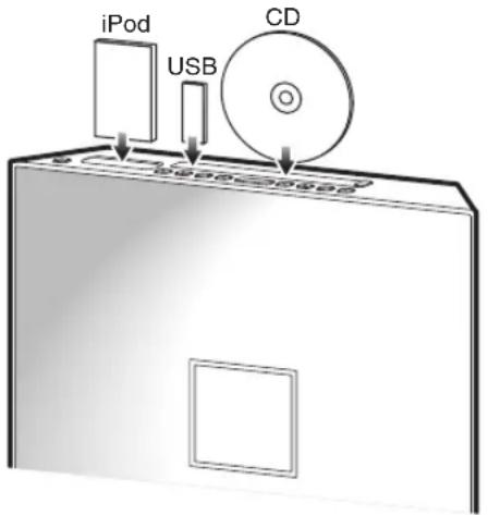
- Install the audio unit in a location where the unit's buttons will be easily accessible. Leave enough space around the unit so that you can easily insert a CD or connect a USB device, or iPod, etc. to the unit.
PACKAGE CONTENTS
Make sure the package contains the following items.
Attachment (AT-800)
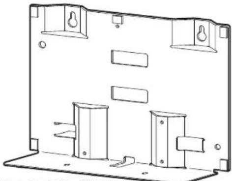
natural_image
Technical line drawing of a mechanical housing or enclosure component (no text or symbols)Weight: 1.3 kg (2.9 lbs)
Safety wire (x2)
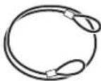
Length: 300 mm (11-3/4")
Washer (x2)

(for M6, 16 mm (5/8") of outer diameter)
Have the following items ready in addition:
- Commercially available tapping screws (x4) (ø 6 mm (1/4"), 31 mm (1-1/4") or more in length, 7 mm (1/4") or more in screw head diameter)
- M4 screws that came with the audio unit (x4) (If the screws are being used to mount the audio unit on a dedicated stand, remove the screws.)
• Phillips(+) screwdriver (Do not use electric tools.)
ASSEMBLING PROCEDURE
Make sure that you leave adequate ventilation space around the unit and follow the instructions below. Be sure to use the specified mounting screws for installation to prevent the audio unit from falling. Illustrations for each step use the ISX-800.
Attaching the screws to the wall
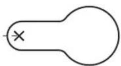
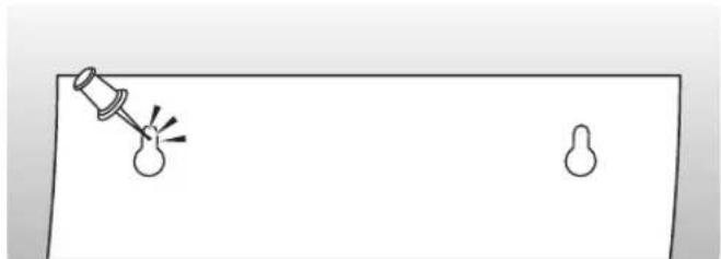
1 Use the template on the back cover to mark screw positions on the wall with a pin.
natural_image
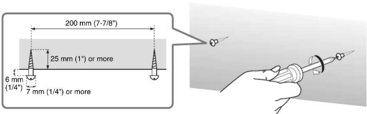
Simple line drawing of a light bulb with a pin and two small shapes on a flat surface (no text or symbols)2 Remove the template, and then attach commercially-available tapping screws (ø6 mm (1/4")) in the marked positions.
To prevent the wall surface from being damaged, drill pilot holes, then attach the screws.
Notes
- Choose a secure wall or beam to fasten the screws. Do not install them into walls made of weak material that can easily come off, such as mortar or plywood wall panels. Loose screws could cause the audio unit to fall, resulting in personal injury.
- Do not use screws shorter than the specified length, nails, or double-sided adhesive tape. Otherwise, the audio unit may fall due to wear or vibration, possibly resulting in personal injury.
Installing the Attachment on the audio unit
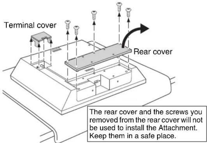
1 Remove the rear cover and terminal cover from the audio unit.
If the audio unit has been mounted on a dedicated stand, remove the stand. Also, remove the power cable, antenna and/or external devices.
Four M4 screws that you remove from the stand will be used in Step 3.
Note
Spread a soft cloth under the audio unit to avoid any damage to the audio unit or work surface.
For more information, refer to the Assembly Guide for the ISX-800.
2 Connect the power cable, antenna and/or external devices.
Pass the cables through a hole in the bottom of the Attachment, then connect them to the audio unit. After connecting the cables, replace the terminal cover.
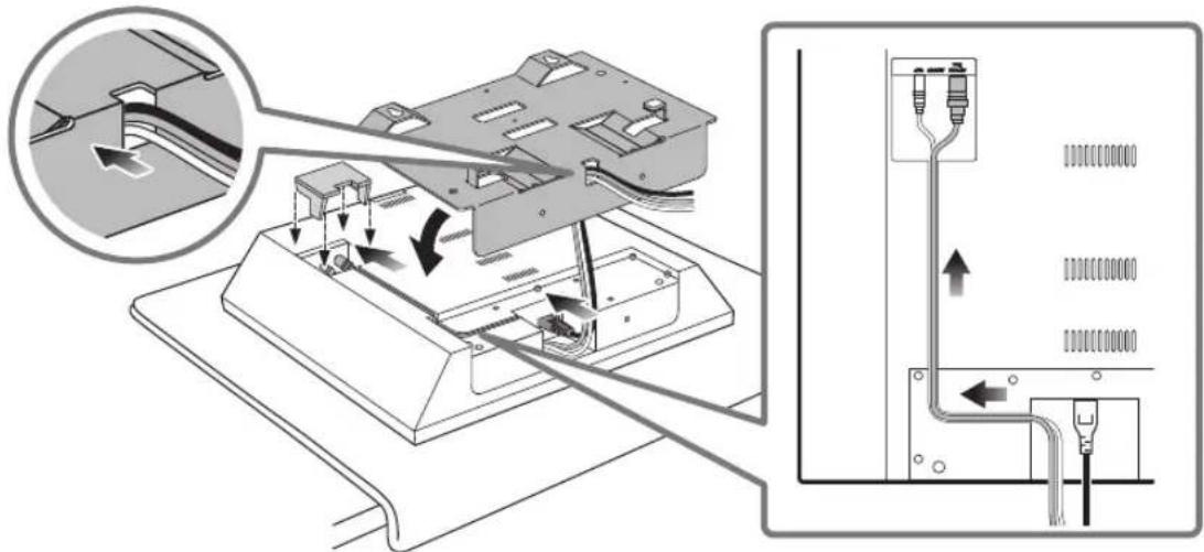
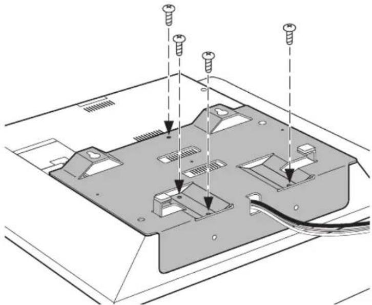
3 Install the Attachment on the audio unit.
Attach four M4 screws that came with the audio unit (for attaching the stand to the audio unit).
Do not tighten the screws using excessive force. Do not use electric tools.
Notes
- Be careful not to pinch the cables between the Attachment and audio unit.
• Make sure that you identify the screws for the rear cover and the screws for the stand correctly. - If you tighten the screws on a slant, the screw threads in the audio unit might break.
natural_image
Technical diagram of a computer monitor rear panel with screw fasteners inserted (no text or labels)Installing the audio unit on the wall
1 Attach the safety wires to the Attachment.
Attach the safety wires as shown in the figure on the right.
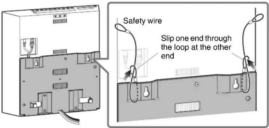
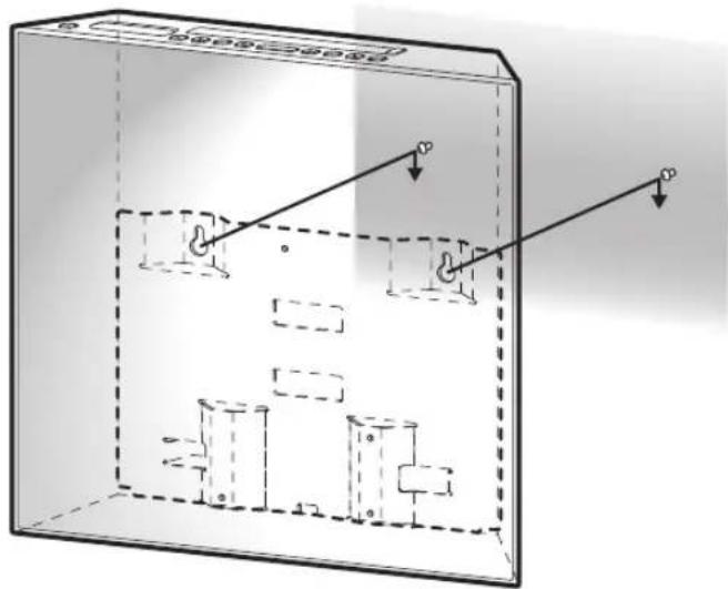
2 Installing the audio unit on the wall.
Hang the audio unit by hooking the mounting holes on the upper part of the Attachment onto the screws in the wall.
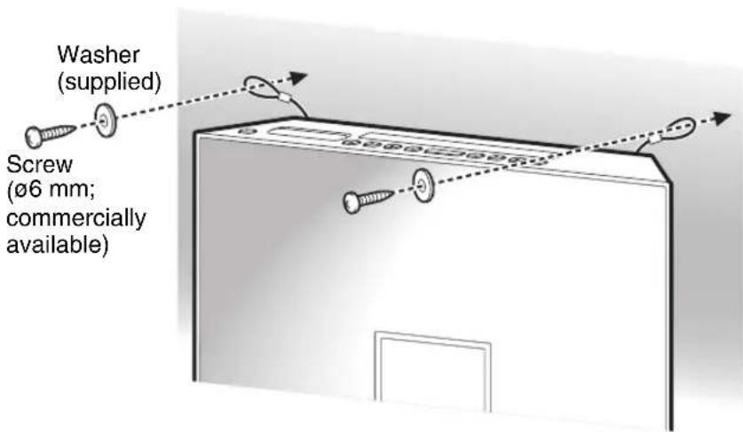
3 Attach the safety wires to the wall.
Pass the screws (commercially available) through the washers (supplied), and then through the loops on the end of the safety wires, and tighten the screws into the wall to secure the safety wires while removing any slack of the wires.
Notes
• Make sure that the screws are strong enough to bear the weight of the audio unit and the Attachment in case they fall.
- Choose a secure wall or beam to fasten the screws.
Notes
- After installation is complete, make sure that the audio unit is securely affixed. Yamaha is not responsible for any accident caused by inappropriate wall conditions or inadequate installation.
- Be sure to secure the cables so that they will not be caught by feet or hands, possibly causing the audio unit to fall.
200 mm (7-7/8")

YAMAHA