WX640 - Log splitter Wallenstein - Free user manual and instructions
Find the device manual for free WX640 Wallenstein in PDF.


User questions about WX640 Wallenstein
0 question about this device. Answer the ones you know or ask your own.
Ask a new question about this device
Download the instructions for your Log splitter in PDF format for free! Find your manual WX640 - Wallenstein and take your electronic device back in hand. On this page are published all the documents necessary for the use of your device. WX640 by Wallenstein.
USER MANUAL WX640 Wallenstein
WALLENSTEIN by EMB MFG INC.
EMB Manufacturing Inc.
4144 Boomer Line · St. Clements, On · N0B 2M0 · Canada
Ph: (519) 699-9283 · Fax: (519) 699-4146
www.embmfg.com
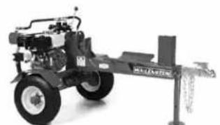
natural_image
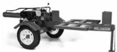
Exterior view of a mechanical vehicle with articulated arms and a mounted platform (no visible text or symbols)WX520
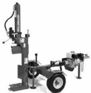
natural_image
Mechanical testing machine with articulated arm and wheels (no visible text or symbols)WX540
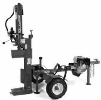
natural_image
Mechanical testing machine with articulated arms and a wheeled chassis (no visible text or symbols)WX640
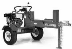
natural_image
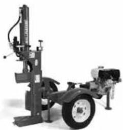
Exterior view of a mechanical vehicle with hydraulic components and a vertical support structure (no visible text or symbols)WX620
natural_image
Mechanical vehicle chassis with wheels and mounting bracket (no visible text or symbols)WX920
natural_image
Mechanical testing machine with articulated arm and wheel (no visible text or symbols)WX980
natural_image
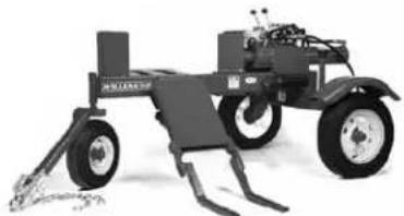
Black-and-white photo of a tracked agricultural machine with visible wheels and a bucket (no text or symbols)WX950
TRAILER WOODSPLITTERS
WX500, WX600 & WX900 SERIES
MODELS WX510, 515, 520, 520T, 530, & 540
MODELS WX615, 620, 620T, 630 & 640
MODELS WX910, 910T, 920, 930, 950, 960, 970 & 980
OPERATOR'S MANUAL
TABLE OF CONTENTS
WARRANTY ....3
DELIVERY INSPECTION REPORT ....4
SERIAL NUMBER LOCATION ....5
1 INTRODUCTION ......6
WX500 SERIES 6
WX600 SERIES 7
WX900 SERIES 7
2 SAFETY 8
2.1 GENERAL SAFETY 9
2.2 EQUIPMENT SAFETY GUIDELINES .....10
2.3 SAFETY TRAINING ....11
2.4 SAFETY SIGNS 11
2.5 PREPARATION 12
2.6 OPERATING SAFETY ......13
2.7 HYDRAULIC SAFETY 14
2.8 STORAGE SAFETY 14
2.9 REFUELLING SAFETY 14
2.10 TIRE SAFETY 14
2.11 TRANSPORT SAFETY 15
2.12 MAINTENANCE SAFETY 15
4.7.3 CLEVIS HITCH: 34
4.8 STORAGE 35
5 SERVICE AND MAINTENANCE ....36
5.1 SERVICE 36
5.1.1 FLUIDS AND LUBRICANTS ....36
5.1.2 GREASING 36
5.1.3 SERVICE ILLUSTRATION ....37
5.1.4 SERVICE RECORD CHART 38
5.2 MAINTENANCE 39
5.2.1 CLEANING AIR CLEANER 39
5.2.2 CHANGING ENGINE OIL 39
5.2.3 HYDRAULIC SYSTEM OIL FILTER .....40
6 TROUBLE SHOOTING ....40
6.1 TROUBLE SHOOTING CHART .....41
7 SPECIFICATIONS 42
7.1 MECHANICAL 42
7.2 HYDRAULIC FITTING TORQUE ....43
7.3 BOLT TORQUE 43
8 ACCESSORIES ....44
W4110 4 WAY SPLITTING WEDGE ....44
W4120 4 WAY SPLITTING WEDGE ....44
W4130 4 WAY SPLITTING WEDGE ....44
W4140 4 WAY SPLITTING WEDGE ....44
INDEX......45

text_image
WALLENSTEINWARRANTY
Effective on products retailed on or after January 1, 2011.
Register your product online at www.embmfg.com within 30 days of purchase to activate warranty.
This product is warranted to be free of defects in materials and workmanship under normal use and service, for a period of
Three (3) Years for Consumer One (1) Year for Commercial/Rental
from the date of purchase, when operated and maintained in accordance with the Operating and Maintenance Instructions supplied with this unit. Warranty is limited to the repair of the product and/or replacement of parts.
This warranty does not cover the following items:
1) Machines or parts lost or damaged during shipment,
2) Normal maintenance or adjustments after initial pre-service and set up is completed
3) Normal replacement of service items.
4) Accessory items / parts not supplied by EMB MFG INC.
5) Damages resulting from:
- misuse, negligence, accident, theft or fire
- use of improper or insufficient fuel, fluids or lubricants
- use of parts or after market accessories other than genuine EMB MFG INC. parts
- modifications, alteration, tampering or improper repair performed by parties other than an authorized dealer
- any device or accessories installed by parties other than an authorized EMB dealer or distributor
Engines are covered by the manufacturer of the engine and covered by the warranty period specified by that manufacturer. Engine warranty must be registered at the engine manufactures website. For service contact your local engine dealer.
Under no circumstances will the manufacturer be liable for any consequential damage or expense of any kind, including loss of profits. The manufacturer is under no circumstances liable for tow vehicle of any kind. The manufacturer is not liable for the maintenance of the product.
This warranty is extended only to the original purchaser and is not transferable. Warranty is void if repairs are attempted by anyone other than a Wallenstein Authorized Service Centre.
If a difficulty develops with the product, contact the local dealer from which you purchased the unit. Only Wallenstein authorized dealers are authorized to make repairs to the product or affect the replacement of defective parts, which will be done at no charge within a reasonable time after the receipt of the product. Unit or parts shall be returned at the customer's expense to the Authorized Service Centre. Damage in transit is not covered by warranty. Include the original purchase receipt with any claim (keep a copy of the receipt for your files).
The distributor's liability under warranty is limited to the repair of the product and/or replacement of parts and is given to the purchaser in lieu of all other remedies including incidental and consequential charges. There are no warranties, expressed or implied, other than those specified herein.
EMB MFG Inc
4144 Boomer Line, St Clements, ON N0B 2M0 Canada
Phone: 519-699-9283 Fax: 519-699-4146 : attention to Warranty Dept
Email: warranty@embmfg.com
WALLENSTEIN TRAILER WOODSPLITTER
DELIVERY INSPECTION REPORT
This form must be filled out by the dealer and signed by both the dealer and the customer at the time of delivery.
Customer's Name Dealer Name
Address Address
City, State/Province, Code City, State/Province, Code
Phone Number ( ) Phone Number ( )
Contact Name ____
Model ____
Serial Number ____
DEALER INSPECTION REPORT
Check For Hydraulic Leaks
____ Check That Cylinder Extends Freely
Fasteners Tight
Lubricate Machine
____ Retainers Installed Through Drawbar Pin
or Ball Hitch Mechanism
Check Tire Pressure
Check Engine Fluid Levels
Check Hydraulic Reservoir Level
SAFETY
____ Safety Chain on Hitch
All Decals Installed
Guards and Shields Installed and Secured
_ Review Operating and Safety Instructions
Delivery Date
I have thoroughly instructed the buyer on the above described equipment which review included the Operator's Manual content, equipment care, adjustments, safe operation and applicable warranty policy.
Date
Dealer's Rep. Signature ____
The above equipment and Operator's Manual have been received by me and I have been thoroughly instructed as to care, adjustments, safe operation and applicable warranty policy.
Date ____
Owner's Signature
To activate warranty, register your product online at www.embmfg.com
SERIAL NUMBER LOCATION
Always give your dealer the serial number of your Wallenstein Trailer Woodsplitter when ordering parts or requesting service or other information.
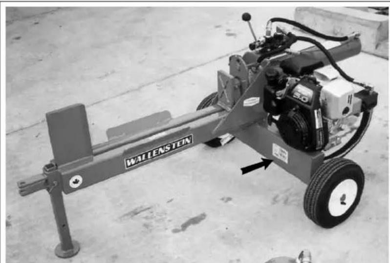
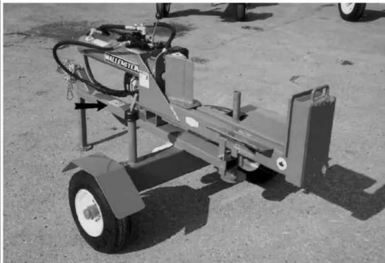
The serial number plates are generally located where indicated below. Please mark the numbers in the spaces provided for easy reference.
natural_image
Industrial machine labeled 'WALLENSTEN' mounted on a wheeled platform, no visible text or symbols beyond the label.WX510
natural_image
Exterior view of a portable industrial machine with wheels and control panel (no visible text or symbols)WX540
SERIAL NUMBER LOCATION
Model Number
Splitter Serial Number
1 INTRODUCTION
Congratulations on your choice of a Wallenstein Trailer Woodsplitter to complement your log splitting operation. This equipment has been designed and manufactured to meet the needs of a discriminating buyer for the efficient splitting of logs.
Safe, efficient and trouble free operation of your Woodsplitter requires that you and anyone else who will be operating or maintaining the machine, read and understand the Safety, Operation, Maintenance and Trouble Shooting information contained within the Operator's Manual.
This manual covers the Wallenstein Trailer Woodsplitters, WX500, WX600 and WX900 Series. Use the Table of Contents and Index as a guide to locate required information.
Refer to your engine instruction manual for specific operating, maintenance instructions and requirements. Engine instruction manual is stored in the manual tube with this operator manual. Engine warranty must be registered at the engine manufactures website.
Keep this manual handy for frequent reference and to pass on to new operators or owners. Call your Wallenstein dealer, distributor or the factory if you need assistance, information or additional copies of the manuals.
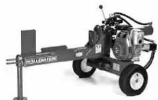
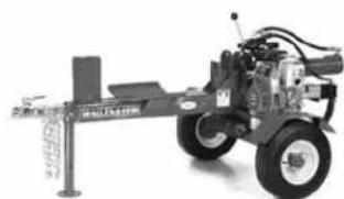
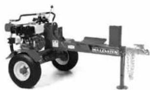
WX500 SERIES
Models WX510, WX515, WX520, W520T, WX530, WX540
natural_image
Exterior view of a mechanical pump or robotic device with no visible text or symbolsWX510
natural_image
Mechanical assembly with articulated arms and wheels (no visible text or symbols)WX515 WX520
natural_image
Exterior view of a mechanical agricultural machine with visible wheels and a mounted shaft (no text or symbols)
natural_image
Exterior view of a mechanical vehicle with attached support structure (no visible text or symbols)WX520T WX530 WX540
natural_image
Mechanical testing machine with a vertical support structure and wheels (no visible text or symbols)
natural_image
Mechanical testing machine with a wheeled base and wheels (no visible text or symbols)WX600 SERIES
Models WX615, W615T, WX620, WX630, WX640
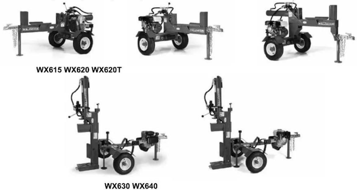
WX900 SERIES
Models WX910, WX910T, WX920, WX930, WX950, WX960, WX970 and WX980
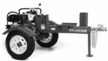
natural_image
Exterior view of a black-and-white industrial vehicle with wheels and a mounted bracket (no visible text or symbols)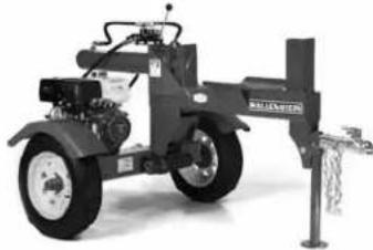
natural_image
Exterior view of a black industrial machine with attached support structure (no visible text or symbols)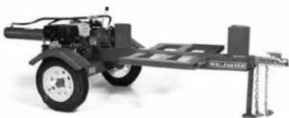
natural_image
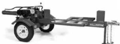
Mechanical vehicle with wheels and a support structure (no visible text or symbols)WX910 WX910T WX920
natural_image
Mechanical vehicle with wheels and a support frame, no visible text or symbolsWX930
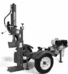
natural_image
Mechanical testing machine with articulated arms and a wheel (no visible text or symbols)WX980
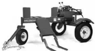
natural_image
Black industrial robotic vehicle with wheels and levers, no visible text or symbolsWX950
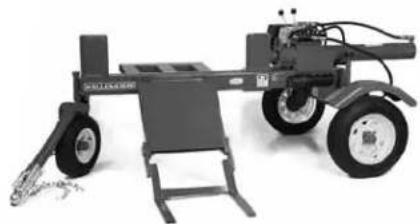
natural_image
Mechanical vehicle with wheels and a small support frame (no visible text or symbols)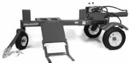
natural_image
Mechanical vehicle with wheels and a flat base, no visible text or symbolsWX970WX960
2 SAFETY
This Safety Alert symbol means ATTENTION! BECOME ALERT! YOUR SAFETY IS INVOLVED!
The Safety Alert symbol identifies important safety messages on the Wallenstein Woodsplitter and in the manual. When you see this symbol, be alert to the possibility of personal injury or death. Follow the instructions in the safety message.
Why is SAFETY important to you?
3 Big Reasons
Accidents Disable and Kill Accidents Cost Accidents Can Be Avoided
SIGNAL WORDS:
Note the use of the signal words DANGER, WARNING and CAUTION with the safety messages. The appropriate signal word for each message has been selected using the following guide-lines:
DANGER - Indicates an imminently hazardous situation that, if not avoided, will result in death or serious injury. This signal word is to be limited to the most extreme situations typically for machine components which, for functional purposes, cannot be guarded.
WARNING - Indicates a potentially hazardous situation that, if not avoided, could result in death or serious injury, and includes hazards that are exposed when guards are removed. It may also be used to alert against unsafe practices.
CAUTION - Indicates a potentially hazardous situation that, if not avoided, may result in minor or moderate injury. It may also be used to alert against unsafe practices.
If you have any questions not answered in this manual or require additional copies or the manual is damaged, please contact your dealer or Wallenstein, 4144 Boomer Line, St. Clements, ON, N0B 2M0. Phone (519) 699-9283 or Fax (519) 699-4146.
SAFETY
YOU are responsible for the SAFE operation and maintenance of your Wallenstein Trailer Wood-splitter. YOU must ensure that you and anyone else who is going to operate, maintain or work around the Woodsplitter be familiar with the operating and maintenance procedures and related SAFETY information contained in this manual.
This manual will take you step-by-step through your working day and alerts you to all good safety practices that should be adhered to while operating the Woodsplitter.
Remember, YOU are the key to safety. Good safety practices not only protect you but also the people around you. Make these practices a working part of your safety program. Be certain that EVERYONE operating this equipment is familiar with the recommended operating and maintenance procedures and follows all the safety precautions. Most accidents can be prevented. Do not risk injury or death by ignoring good safety practices.
- Woodsplitter owners must give operating instructions to operators or employees before allowing them to operate the machine, and at least annually.
- The most important safety feature on this equipment is a SAFE operator. It is the operator's responsibility to read and understand ALL Safety and Operating instructions in the manual and to follow these. Most accidents can be avoided.
- A person who has not read and understood all operating and safety instructions is not qualified to operate the machine. An untrained operator exposes himself and bystanders to possible serious injury or death.
- Do not modify the equipment in any way. Unauthorized modification may impair the function and/or safety and could affect the life of the equipment.
- Think SAFETY! Work SAFELY!
2.1 GENERAL SAFETY
- Read and understand the Operator's Manual and all safety signs before operating, maintaining, adjusting or unplugging the Woodsplitter.
- Have a first-aid kit available for use should the need arise and know how to use it.
- Have a fire extinguisher available for use should the need arise and know how to use it.
- Do not allow riders.
- Wear appropriate protec-
tive gear. This list includes but is not limited to:
- A hard hat
- Protective shoes with slip resistant soles
- Protective goggles, glasses or face shield
- Heavy gloves
-
Protective clothing
-
Install and secure all guards before starting.
- Wear suitable ear protection for prolonged exposure to excessive noise.
- Place all controls in neutral, stop engine, set park brake, remove ignition key and wait for all moving parts to stop before servicing, adjusting, repairing or unplugging.
- Clear the area of people, especially small children, before starting.
- Review safety related items annually with all personnel who will operating or maintaining the Woodsplitter.




natural_image
Illustration of a person wearing various safety gear and clothing (no text or symbols)
2.2 EQUIPMENT SAFETY GUIDELINES
- Safety of the operator and bystanders is one of the main concerns in designing and developing a machine. However, every year many accidents occur which could have been avoided by a few seconds of thought and a more careful approach to handling equipment. You, the operator, can avoid many accidents by observing the following precautions in this section. To avoid personal injury or death, study the following precautions and insist those working with you, or for you, follow them.
- In order to provide a better view, certain photographs or illustrations in this manual may show an assembly with a safety shield removed. However, equipment should never be operated in this condition. Keep all shields in place. If shield removal becomes necessary for repairs, replace the shield prior to use.
- Replace any safety sign or instruction sign that is not readable or is missing. Location of such safety signs is indicated in this manual.
- Never use alcoholic beverages or drugs which can hinder alertness or coordination while operating this equipment. Consult your doctor about operating this machine while taking prescription medications.
-
Under no circumstances should young children be allowed to work with this equipment. Do not allow persons to operate or assemble this unit until they have read this manual and have developed a thorough understanding of the safety precautions and of how it works. Review the safety instructions with all users annually.
-
This equipment is dangerous to children and persons unfamiliar with its operation. The operator should be a responsible, properly trained and physically able person familiar with farm machinery and trained in this equipment's operations. If the elderly are assisting with work, their physical limitations need to be recognized and accommodated.
- Use a tractor equipped with a Roll Over Protective Structure (ROPS) and a seat belt.
- Never exceed the limits of a piece of machinery. If its ability to do a job, or to do so safely, is in question - DON'T TRY IT.
- Do not modify the equipment in any way. Unauthorized modification result in serious injury or death and may impair the function and life of the equipment.
- In addition to the design and configuration of this implement, including Safety Signs and Safety Equipment, hazard control and accident prevention are dependent upon the awareness, concern, prudence, and proper training of personnel involved in the operation, transport, maintenance, and storage of the machine. Refer also to Safety Messages and operation instruction in each of the appropriate sections of the Tractor and machine Manuals. Pay close attention to the Safety Signs affixed to the tractor and the machine.
2.3 SAFETY TRAINING
- Safety is a primary concern in the design and manufacture of our products. Unfortunately, our efforts to provide safe equipment can be wiped out by a single careless act of an operator or bystander.
- In addition to the design and configuration of equipment, hazard control and accident prevention are dependent upon the awareness, concern, prudence and proper training of personnel involved in the operation, transport, maintenance and storage of this equipment.
- It has been said, "The best safety feature is an informed, careful operator." We ask you to be that kind of an operator. It is the operator's responsibility to read and understand ALL Safety and Operating instructions in the manual and to follow these. Accidents can be avoided.
- Working with unfamiliar equipment can lead to careless injuries. Read this manual, and the manual for your tractor, before assembly or operating, to acquaint yourself with the machines. If this machine is used by any person other than yourself, or is loaned or rented, it is the machine owner's responsibility to make certain that the operator, prior to operating:
a. Reads and understands the operator's manuals.
b. Is instructed in safe and proper use.
- Know your controls and how to stop tractor, engine, and machine quickly in an emergency. Read this manual and the one provided with your tractor.
- Train all new personnel and review instructions frequently with existing workers. Be certain only a properly trained and physically able person will operate the machinery. A person who has not read and understood all operating and safety instructions is not qualified to operate the machine. An untrained operator exposes himself and bystanders to possible serious injury or death. If the elderly are assisting with farm work, their physical limitations need to be recognized and accommodated.
2.4 SAFETY SIGNS
- Keep safety signs clean and legible at all times.
- Replace safety signs that are missing or have become illegible.
- Replaced parts that displayed a safety sign should also display the current sign.
- Safety signs are available from your authorized Distributor or Dealer Parts Department or the factory.
How to Install Safety Signs:
- Be sure that the installation area is clean and dry.
- Be sure temperature is above 50^ (10°C).
- Determine exact position before you remove the backing paper. (See Section 3).
- Remove the smallest portion of the split backing paper.
- Align the sign over the specified area and carefully press the small portion with the exposed sticky backing in place.
- Slowly peel back the remaining paper and carefully smooth the remaining portion of the sign in place.
- Small air pockets can be pierced with a pin and smoothed out using the piece of sign backing paper.
2.5 PREPARATION
-
Never operate the tractor and machine until you have read and completely understand this manual, the Tractor and Engine Operator's Manual, and each of the Safety Messages found on the safety signs on the tractor, engine and machine.
-
Personal protection equipment including hard
hat, safety glasses, safety shoes, and gloves are recommended during assembly, installation, operation, adjustment, maintaining, repairing, removal, or

natural_image
Silhouette of a worker wearing a hard hat and safety gear, surrounded by other clothing items (no text or symbols)moving the implement. Do not allow long hair, loose fitting clothing or jewellery to be around equipment.
3. PROLONGED EXPOSURE TO LOUD NOISE MAY CAUSE PERMANENT HEARING LOSS!
Tractors with or without equipment attached
can often be noisy enough to cause permanent, partial hearing loss. We recommend that you wear hearing protection on a full-time basis if the noise in the Operator's position exceeds 80db. Noise
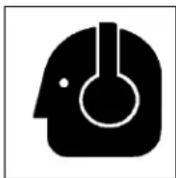
over 85db on a long-term basis can cause severe hearing loss. Noise over 90db adjacent to the Operator over a long-term basis may cause permanent, total hearing loss. NOTE: Hearing loss from loud noise (from tractors, chain saws, radios, and other such sources close to the ear) is cumulative over a lifetime without hope of natural recovery.
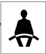
- Operate the machine only with a tractor equipped with an approved Roll-Over-Protective Structure (ROPS).
Always wear your seat belt. Serious injury or even death could result from falling off the tractor ---particularly during a turnover when the operator could be pinned under the ROPS or the tractor.
natural_image
Silhouette of a seated person with a rod, no text or symbols present-
Clear working area of stones, branches or hidden obstacles that might be hooked or snagged, causing injury or damage.
-
Operate only in daylight or good artificial light.
-
Be sure machine is properly mounted, adjusted and in good operating condition.
-
Ensure that all safety shielding and safety signs are properly installed and in good condition.
- Please remember it is important that you read and heed the safety signs on the Woodsplitter. Clean or replace all safety signs if they cannot be clearly read and understood. They are there for your safety, as well as the safety of others. The safe use of this machine is strictly up to you, the operator.
- All things with moving parts are potentially hazardous. There is no substitute for a cautious, safe-minded operator who recognizes potential hazards and follows reasonable safety practices. The manufacturer has designed this Woodsplitter to be used with all its safety equipment properly attached, to minimize the chance of accidents. Study this manual to make sure you have all safety equipment attached.
- If a safety shield or guard is removed for any reason, it must be replaced before the machine is again operated.
- Personal protection equipment including hard hat, safety glasses, hearing protection, safety shoes, and tight gloves are recommended during assembly, installation, operation, adjustment, maintaining, repairing, removal, or moving. Do not allow long hair, loose fitting clothing, or jewellery to be around moving parts.
- Always use two people to handle heavy, unwieldy components during assembly, installation, removal or moving.
- Never place any part of your body, fingers, hands, feet, etc. where it would be in danger if movement should occur during assembly, installation, operation, maintaining, repairing, removal or moving. Keep others away.
- Do not allow bystanders within 20 feet of machine during operation. Wood chips can fly out and injure others.
- Do not step over or straddle splitter during operation.
-
Do not try to split more than one log at a time. The extra log can fly out and cause injury.
-
Keep your fingers and hands away from cracks in the log that can open while splitting.
- Always load logs by holding on the sides, not the top and bottom.
- Do not load the splitter when the wedge is in motion.
- Do not try to split logs across the grain. Some kinds can burst or splinter and fly out of machine causing injury.
- For uneven cut logs, always place the wide end down and the most square end against the splitting wedge.
- Never use alcoholic beverages or drugs which can hinder alertness or coordination while operating this equipment. Consult your doctor about operating this machine while taking prescription medications.
- Do not allow riders on the machine or tractor at any time. There is no safe place for any riders.
- Before you operate the machine, check over all pins, bolts, connections and hydraulic components to be sure all are securely in place and tight. Tighten or replace any leaking, damaged or worn parts immediately.
- Do not allow anyone who is not familiar with the safety rules and operation instructions to use this machine.
- Never allow children to operate or be around this machine.
- Do not operate on slopes or hillsides. Sloping terrain can cause logs to roll or slip.
- Clear the work area of objects which might be picked up and snagged or entangled in the machine. Do not operate on slippery, wet, muddy or icy surfaces. Good footing prevents slipping and tripping.
2.7 HYDRAULIC SAFETY
-
Make sure that all the components in the hydraulic system are kept in good condition and are clean.
-
Replace any worn, cut, abraded, flattened or crimped hoses and metal lines.
-
Stop engine or motor, disconnect spark plug wire or unplug power cord, and wait for all moving parts to stop before servicing, adjusting, repairing or cleaning.
-
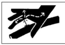
Do not attempt any makeshift repairs to the hydraulic lines, fittings or hoses by using tapes, clamps or cements. The hydraulic system operates under extremely high-pressure. Such repairs will fail suddenly and create a hazardous and unsafe condition.
-
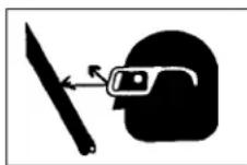
Wear proper hand and eye protection when searching for a high-pressure hydraulic leak. Use a piece of wood or cardboard as a backstop instead of hands to isolate and identify a leak.
-
If injured by a concentrated high-pressure stream of hydraulic fluid, seek medical attention immediately. Serious infection or toxic reaction can develop from hydraulic fluid piercing the skin surface.
-
Before applying pressure to the system, make sure all components are tight and that lines, hoses and couplings are not damaged.
- Think SAFETY! Work SAFELY!
2.8 STORAGE SAFETY
- Store the unit in an area away from human activity.
- Do not permit children to play on or around the stored machine.
- Store the unit in a dry, level area. Support the frame with planks if required.
2.9 REFUELLING SAFETY
- Handle fuel with care. It is highly flammable.
- Allow engine to cool for 5 minutes before refuelling. Clean up spilled fuel before restarting engine.
- Do not refuel the machine while smoking or when near open flame or sparks.
- Fill fuel tank outdoors.
- Prevent fires by keeping machine clean of accumulated trash, grease and debris.

text_image
No smoking sign with crossed-out cigarette and smoke symbol2.10 TIRE SAFETY
- Failure to follow proper procedures when mounting a tire on a wheel or rim can produce an explosion which may result in serious injury or death.
- Do not attempt to mount a tire unless you have the proper equipment and experience to do the job.
- Have a qualified tire dealer or repair service perform required tire maintenance.
- When replacing worn tires, make sure they meet the original tire specifications. Never undersize.
2.11 TRANSPORT SAFETY
- Comply with state and local laws governing highway safety and movement of machinery on public roads.
- The use of flashing amber lights is acceptable in most localities. However, some localities prohibit their use. Local laws should be checked for all highway lighting and marking requirements.
- At all times, when driving the tractor and equipment on the road or highway under 20 mph (32 kph) use flashing amber warning lights and a slow moving vehicle (SMV) identification emblem. Do not exceed 20 mph (32 kph). Reduce speed on rough roads and surfaces.
- Plan your route to avoid heavy traffic.
- Be sure the trailer is hitched positively to the towing vehicle and a retainer is used through the hitch coupler. Always attach a safety chain between the hitch and the towing vehicle.
- Always install transport locks, pins or brackets before transporting.
- Do not drink and drive.
- Be a safe and courteous driver. Always yield to oncoming traffic in all situations, including narrow bridges, intersections, etc. Watch for traffic when operating near or crossing roadways.
- Never allow riders on either tractor or machine.
2.12 MAINTENANCE SAFETY
- Good maintenance is your responsibility. Poor maintenance is an invitation to trouble.
-
Follow good shop practices.
-
Keep service area clean and dry.
- Be sure electrical outlets and tools are properly grounded.
- Use adequate light for the job at hand.
natural_image
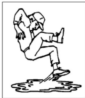
Illustration of a person in motion, possibly dancing or falling (no text or symbols)- Make sure there is plenty of ventilation. Never operate the engine of the towing vehicle in a closed building. The exhaust fumes may cause asphyxiation.
- Before working on this machine, shut off the engine, set the brakes, and remove the ignition keys.
- Never work under equipment unless it is blocked securely.
- Use personal protection devices such as eye, hand and hearing protectors, when performing any service or maintenance work.
- Where replacement parts are necessary for periodic maintenance and servicing, genuine factory replacement parts must be used to restore your equipment to original specifications. The manufacturer will not be responsible for injuries or damages caused by use of unapproved parts and/or accessories.
- A fire extinguisher and first aid kit should be
kept readily accessible while performing maintenance on this equipment.


- Periodically tighten all bolts, nuts and screws and check that all cotter pins are properly installed to ensure unit is in a safe condition.
- When completing a maintenance or service function, make sure all safety shields and devices are installed before placing unit in service.
- DO NOT run engine in an enclosed area. Exhaust gases contain carbon monoxide, an odourless and deadly poison.
- DO NOT place hands or feet near moving or rotating parts.
- DO NOT store, spill, or use gasoline near an open flame, or devices such as a stove, furnace, or water heater which use a pilot light or devices which can create a spark.
- DO NOT refuel indoors where area is not well ventilated. Outdoor refuelling is preferred.
- DO NOT fill fuel tank while engine is running. Allow engine to cool for 5 minutes before refueling. Store fuel in approved safety containers.
- DO NOT remove fuel tank cap while engine is running.
- DO NOT operate engine if gasoline is spilled. Move machine away from the spill and avoid creating any ignition until gasoline has evaporated.
- DO NOT smoke while filling fuel tank.
- DO NOT choke carburettor to stop engine. Whenever possible, gradually reduce engine speed before stopping.
- DO NOT run engine above rated speeds. This may result in injury.
- DO NOT tamper with governor springs, governor links or other parts which may increase the governed speed.
- DO NOT tamper with the engine speed selected by the original equipment manufacturer.
- DO NOT check for spark with spark plug or spark plug wire removed.
14 DO NOT crank engine with spark plug removed. If engine is flooded, place throttle in "FAST" position and crank until engine starts.
15. DO NOT strike flywheel with a hard object or metal tool as this may cause flywheel to shatter in operation. Use proper tools to service engine.
16 DO NOT operate engine without a muffler. Inspect periodically and replace, if necessary. If engine is equipped with a muffler deflector, inspect periodically and replace, if necessary with correct deflector.
17. DO NOT operate engine with an accumulation of grass, leaves, dirt or other combustible materials in the muffler area.
18. DO NOT use this engine on any forest covered, brush covered, or grass covered unimproved land unless a spark arrester is installed on the muffler. The arrester must be maintained in effective working order by the operator. In the state of California the above is required by law (Section 4442 of the California Public Resources Code). Other states may have similar laws. Federal laws apply on federal land.
19. DO NOT touch hot muffler, cylinder or fins because contact may cause burns.
20. DO NOT run engine with air cleaner or air cleaner cover removed.
WARNING: DO
- ALWAYS DO remove the wire from the spark plug when servicing the engine or equipment TO PREVENT ACCIDENTAL STARTING. Disconnect the negative wire from the battery terminal if equipped with a 12 volt starting system.
- DO keep cylinder fins and governor parts free of grass and other debris which can affect engine speed.
- DO examine muffler periodically to be sure it is functioning effectively. A worn or leaking muffler should be repaired or replaced as necessary.
- DO use fresh gasoline. Stale fuel can gum carburettor and cause leakage.
- DO check fuel lines and fittings frequently for cracks or leaks. Replace if necessary.
2.14 SIGN-OFF FORM
Wallenstein follows the general Safety Standards specified by the American Society of Agricultural Engineers (ASAE) and the Occupational Safety and Health Administration (OSHA). Anyone who will be operating and/or maintaining the Woodsplitter must read and clearly understand ALL Safety, Operating and Maintenance information presented in this manual.
Do not operate or allow anyone else to operate this equipment until such information has been reviewed. Annually review this information before the season start-up.
Make these periodic reviews of SAFETY and OPERATION a standard practice for all of your equipment. We feel that an untrained operator is unqualified to operate this machine.
A sign-off sheet is provided for your record keeping to show that all personnel who will be working with the equipment have read and understand the information in the Operator's Manual and have been instructed in the operation of the equipment.
SIGN-OFF FORM
| DATE | EMPLOYEES SIGNATURE | EMPLOYERS SIGNATURE |
3 SAFETY SIGN LOCATIONS
3.1 SAFETY SIGN LOCATIONS - 3 PANEL
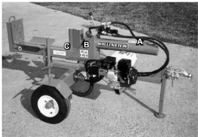
The types of safety signs and locations on the equipment are shown in the illustration below. Safety signs are located in the same general area's across all the models covered in this manual. Good safety requires that you familiarize yourself with the various safety signs, the type of warning and the area, or particular function related to that area, that requires your SAFETY AWARENESS.
natural_image
Exterior view of a wallenstein industrial machine with labeled parts (A, B, C) on the side (no readable text beyond labels)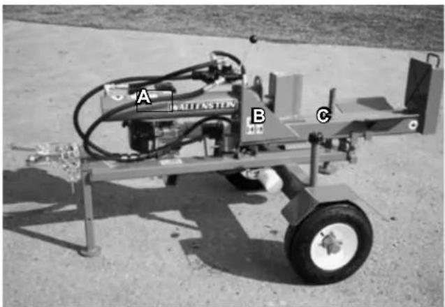
natural_image
Exterior view of a mechanical testing machine with labeled parts A, B, and C (no readable text or symbols beyond labels)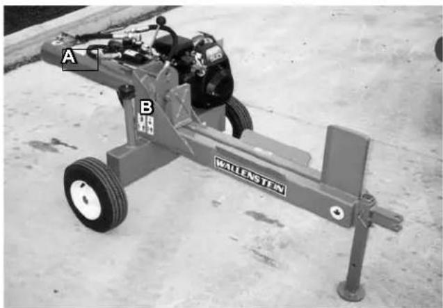
natural_image
Mechanical testing machine labeled 'WALLENSTEN' with two parts marked A and B, placed on a concrete floor (no visible text beyond labels)A
text_image
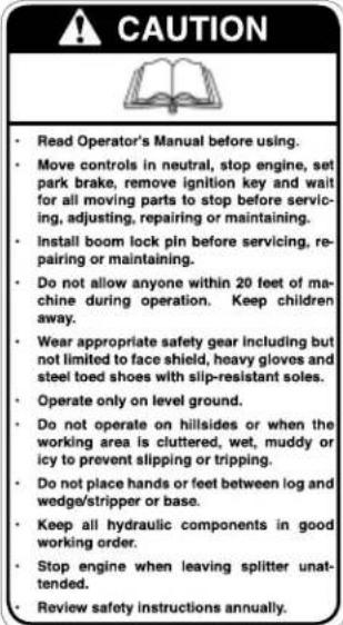
CAUTION Read Operator's Manual before using. Move controls in neutral, stop engine, set park brake, remove ignition key and wait for all moving parts to stop before servicing, adjusting, repairing or maintaining. Install boom lock pin before servicing, repairing or maintaining. Do not allow anyone within 20 feet of machine during operation. Keep children away. Wear appropriate safety gear including but not limited to face shield, heavy gloves and steel toed shoes with slip-resistant soles. Operate only on level ground. Do not operate on hillsides or when the working area is cluttered, wet, muddy or icy to prevent slipping or tripping. Do not place hands or feet between log and wedge/stripper or base. Keep all hydraulic components in good working order. Stop engine when leaving splitter unattended. Review safety instructions annually.Z94139
B
text_image
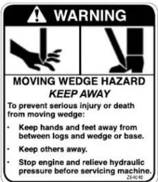
WARNING MOVING WEDGE HAZARD KEEP AWAY To prevent serious injury or death from moving wedge: - Keep hands and feet away from between logs and wedge or base. - Keep others away. - Stop engine and relieve hydraulic pressure before servicing machine.Z94140
text_image
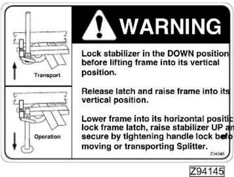
WARNING Lock stabilizer in the DOWN position before lifting frame into its vertical position. Release latch and raise frame into its vertical position. Lower frame into its horizontal positc lock frame latch, raise stabilizer UP an secure by tightening handle lock befo moving or transporting Splitter. Z94145 Transport OperationREMEMBER - If safety signs have been damaged, removed, become illegible or parts replaced without signs, new signs must be applied. New signs are available from your authorized dealer.
3.2 SAFETY SIGN LOCATIONS - 2 PANEL
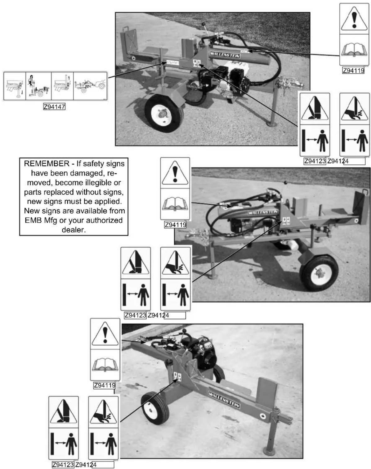
The types of safety signs and locations on the equipment are shown in the illustration below. Safety signs are located in the same general area's across all the models covered in this manual. . Good safety requires that you familiarize yourself with the various safety signs, the type of warning and the area, or particular function related to that area, that requires your SAFETY AWARENESS.
text_image
WALLESTEN Z94119 Z94123 Z94124 REMEMBER - If safety signs have been damaged, re- moved, become illegible or parts replaced without signs, new signs must be applied. New signs are available from EMB Mfg or your authorized dealer. Z94119 Z94123 Z94124 Z94119 Z94123 Z941244 OPERATION

OPERATING SAFETY
- Read and understand the Operator's Manual and all safety signs before operating, servicing, adjusting, repairing or unplugging.
- Do not allow riders.
• Install and secure all guards and shields before starting or operating. - Keep hands, feet, hair and clothing away from moving parts.
- Place all controls in neutral, stop tractor engine, set park brake, remove ignition key and wait for all moving parts to stop before servicing, adjusting, repairing or unplugging.
- Place all tractor and machine controls in neutral before starting.
• Always wear the appropriate personal safety equipment when operating splitter including but not limited to hard hat, safety shoes, face shield and heavy gloves. - Clear the area of bystanders, especially small children, before starting.
- Do not operate on slopes or side hills.
- Keep working area clean, neat and dry to prevent slipping and tripping.
- Keep all mechanical and hydraulic components in good condition. Do not operate with leaks or damaged components.
- Load splitter by holding logs on the side rather than the top and bottom.
- Do not split wood across the grain.
- Review safety instructions with all operators annually.
4.1 TO THE NEW OPERATOR OR OWNER
The Wallenstein Trailer Woodsplitter is designed to split any kind of wood or log. Be familiar with the machine before starting.
In addition to the design and configuration of equipment, hazard control and accident prevention are dependent upon the awareness, concern, prudence and proper training of personnel involved in the operation, transport, maintenance and storage of equipment. It is the responsibility of the owner or operator to read this manual and to train all other operators before they start working with the machine.
It is the responsibility of the owner or operator to read this manual and to train all other operators before they start working with the machine. Follow all safety instructions exactly. Safety is everyone's business. By following recommended procedures, a safe working environment is provided for the operator, bystanders and the area around the work site. Untrained operators are not qualified to operate the machine.
Many features incorporated into this machine are the result of suggestions made by customers like you. Read this manual carefully to learn how to operate the machine safely and how to set it to provide maximum field efficiency. By following the operating instructions in conjunction with a good maintenance program, your Woodsplitter will provide many years of trouble-free service.
4.2 MACHINE COMPONENTS
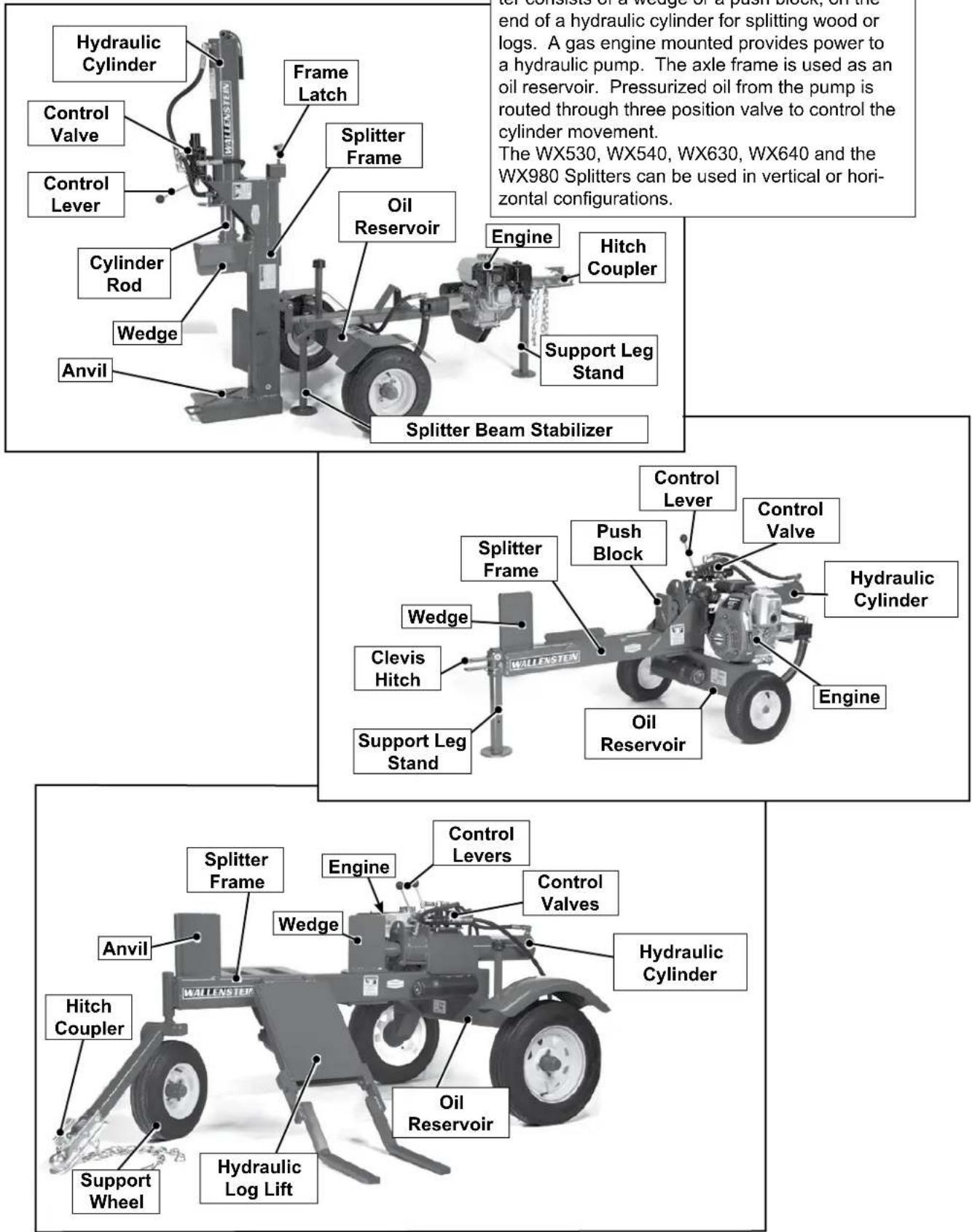
text_image
Hydraulic Cylinder Control Valve Control Lever Cylinder Rod Wedge Anvil Frame Latch Splitter Frame Oil Reservoir Engine Hitch Coupler Support Leg Stand Splitter Beam Stabilizer Control Lever Control Valve Push Block Hydraulic Cylinder Clevis Hitch Support Leg Stand Engine Oil Reservoir Anvil Splitter Frame Engine Control Levers Control Valves Wedge Hydraulic Cylinder Hitch Coupler Support Wheel Hydraulic Log LiftFig. 1 MACHINE COMPONENTS
4.3 MACHINE BREAK-IN
Although there are no operational restrictions on the Trailer Woodsplitter when used for the first time, it is recommended that the following mechanical items be checked:
A. After Operating For 1 and 5 Hours:
- Check all nuts, bolts and other fasteners. Tighten to their specified torque level.
- Check hydraulic system for leaks. Tighten all leaking fittings and replace any leaking components.
- Check machine fluid levels: Fuel, engine oil, and hydraulic oil reservoir. Top up as required.
- Check for entangled material. Remove all entangled material before resuming work.
- Check tire pressure. Inflate as required.
B. After Operating For 10 Hours:
- Repeat steps 1 through 5 listed above.
- Change engine oil.
- Go to the normal servicing and maintenance schedule as defined in the Maintenance Section.
4.4 PRE-OPERATION CHECKLIST
Efficient and safe operation of the Wallenstein Trailer Woodsplitter requires that each operator reads and understands the operating procedures and all related safety precautions outlined in this section. A pre-operation checklist is provided for the operator. It is important for both the personal safety and maintaining the good mechanical condition of the Woodsplitter that this checklist is followed.
Before operating the machine and each time thereafter, the following areas should be checked off:
- Lubricate the machine per the schedule outlined in the Maintenance Section.
- Check that the machine is properly attached to the tractor or towing vehicle. Be sure retainers are used through the drawbar pin or ball hitch mechanism.
- Check the wedge and block. Be sure they are not damaged or broken and is not badly worn. Repair or replace as required.
- Check for entangled material. Remove this material.
- Check for hydraulic leaks. Tighten fittings or replace components to stop leaks.
- Check engine and machine fluid levels. Top up as required.
4.5 CONTROLS
Before starting to work, all operators should familiarize themselves with the location and function of the controls.
1. Gas Engine:
A Honda engine is used with the unit. AI-ways read the engine Operator's manual supplied with the machine for the detailed operating procedures.
- Ignition Switch: This rotary switch controls the electrical power to the engine electrical system. Turn the switch clockwise to turn the electrical system ON and the engine will run. Turn counter-clockwise to stop the engine (GX160,GX200,&GX270 only).
- Fuel Shut-Off Valves: Each engine is equipped with a valve between the fuel tank and the carburettor. Slide the fuel valve toward the block to turn ON and away to turn OFF. Turn the fuel OFF when not in use or when transporting.
- Throttle: This lever controls the engine RPM. Move the lever side to side (GX160, GX200, & GX270) or up and down (GC160 & GC190) to increase or decrease the RPM. Always run at maximum throttle while operating. (GC160 & GC190 throttle also shuts engine "off" in down position).
- Choke: The choke controls the fuel/air mixture to the engine. Close the choke when starting if the engine is cold. Open the choke as the engine warms. Always open the choke fully during start-up.
- Starting rope: This retracting rope and T-bar is used to turn the engine over for starting. Grasp the T-bar firmly and pull the rope sharply to start the engine.
Fig. 7 ENGINE CONTROLS
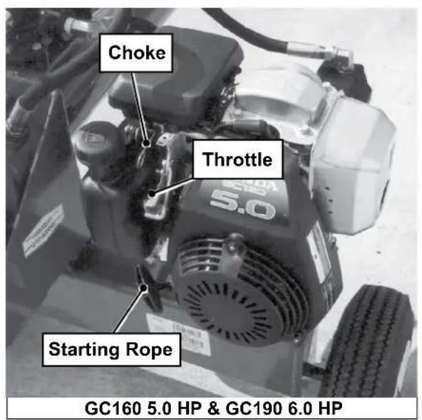
text_image
Choke Throttle Starting Rope GC160 5.0 HP & GC190 6.0 HP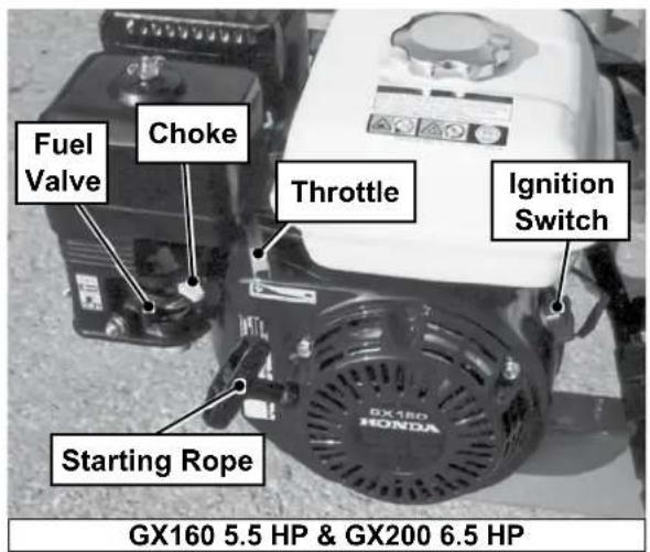
text_image
Fuel Valve Choke Throttle Ignition Switch Starting Rope GX160 5.5 HP & GX200 6.5 HP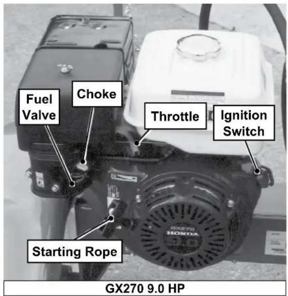
text_image
Fuel Valve Choke Throttle Ignition Switch Starting Rope GX270 9.0 HP2. Hydraulic Controls:
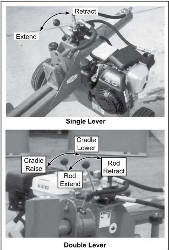
All Woodsplitters are designed with at least one hydraulic lever to control the extending and retracting movement of the cylinder rod.
In addition, the WX950, WX960 and WX970 have another lever to control the lifting cradle.
Rod Position Control Lever All Models:
This 3-position spring-loaded-to-center neutral lever controls the flow of oil to the cylinder.
- Move the lever toward the wood and hold for the cylinder rod to extend and split the wood.
- Move the lever away from the wood and place in detent to retract the cylinder rod.
- Release the lever, it will return to its centered neutral position when the pressure builds up enough to kick the lever out of detent at the end of the stroke.
- The cylinder rod will stop moving.
Cradle Position Control Lever For Models WX950, WX960, WX970:
This 3-position spring-loaded-to-center-neutral lever controls the flow of oil to the cradle position cylinder.
- Move the lever toward the hitch and hold for the cylinder rod to extend and raise the cradle.
- Move the lever away from the hitch and hold to retract the cylinder rod and lower the cradle.
- Release the lever, it will return to its centered neutral position.
- The cylinder rod will stop moving.
text_image
Retract Extend Single Lever Cradle Lower Cradle Raise Rod Extend Rod Retract Double LeverFig. 8 HYDRAULIC CONTROLS
4.6 FIELD OPERATION

OPERATING SAFETY
- Read and understand the Operator's Manual and all safety signs before operating, servicing, adjusting, repairing or unplugging.
- Do not allow riders.
• Install and secure all guards and shields before starting or operating. - Keep hands, feet, hair and clothing away from moving parts.
- Place all controls in neutral, stop tractor engine, set park brake, remove ignition key and wait for all moving parts to stop before servicing, adjusting, repairing or unplugging.
-
Place all tractor and machine controls in neutral before starting.
• Always wear the appropriate personal safety equipment when operating splitter including but not limited to hard hat, safety shoes, face shield and heavy gloves. -
Clear the area of bystanders, especially small children, before starting.
- Do not operate on slopes or side hills.
- Keep working area clean, neat and dry to prevent slipping and tripping.
- Keep all mechanical and hydraulic components in good condition. Do not operate with leaks or damaged components.
- Load splitter by holding logs on the side rather than the top and bottom.
- Do not split wood across the grain.
- Review safety instructions with all operators annually.
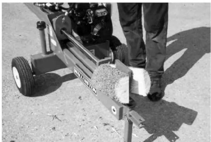
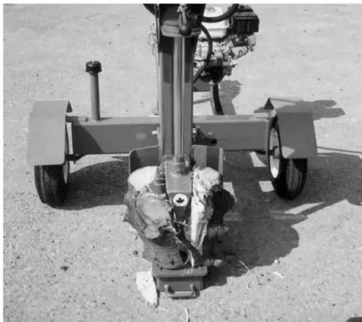
A Wallenstein Trailer Woodsplitter is a self-contained machine designed to move a wedge or a push block through wood to split it. There are several model splitters can be used in the vertical as well as horizontal configuration. The operator has the responsibility of being familiar with all operating and safety procedures and following them.
Each operator should review this section of the manual at the start of the season and as often as required to be familiar with the machine. When using, follow this procedure:
- Clear the area of bystanders, especially small children.
- Review and follow the Pre-operation Checklist (Section 4.4).
- The Woodsplitter can be used as a stand alone machine or attached to a tow unit.
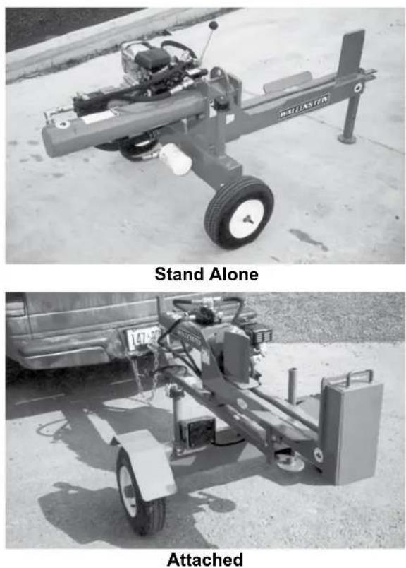
Fig. 9 SETTING UP
1. Operation:
a. Move the machine into its working position next to the wood to be split.
b. Set park brake if connected to tow vehicle.
c. Lower the support leg stand and secure with the snapper pin.
Note: If your model features vertical splitting, see step 10 for converting for vertical splitting
d. Close choke if engine is cold.
e. Move the throttle to its 1/4 to 1/2 throttle position.
f. Open the fuel supply valve. (5.5,6.5 and 9.0 HP engines only)
g. Pull sharply on the starting rope to start the engine.
h. Run the engine for a few minutes to allow it to warm.
i. Gradually open the choke.
j. Slowly increase engine speed to maximum RPM.
Note: If your model features a lifting cradle, see step 8 for operating the cradle.
k. Place wood on the splitting frame against the wedge or anvil.
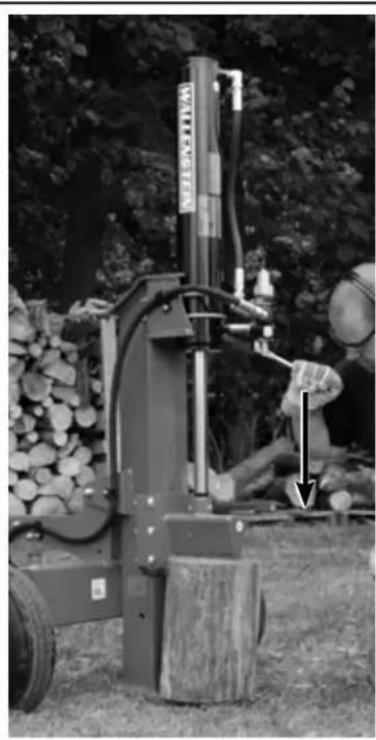
I. Move the lever toward the wood and hold to advance the push block or wedge towards the wood or log to start splitting.
Move the lever toward the wood and hold to advance the push block or wedge towards the wood or log to start splitting.
I. Release the lever when the log splits into 2 pieces or the cylinder rod reaches the end of the stroke, and the rod will stop.
m. Move the lever away from the wood and place in detent to retract the cylinder rod. Release the lever, the cylinder rod will stop moving when it fully retracts, and the lever will return to its centered neutral position.
natural_image
Black-and-white photo of a mechanical tool with a vertical arm and base, mounted on a wooden post outdoors (no visible text or symbols)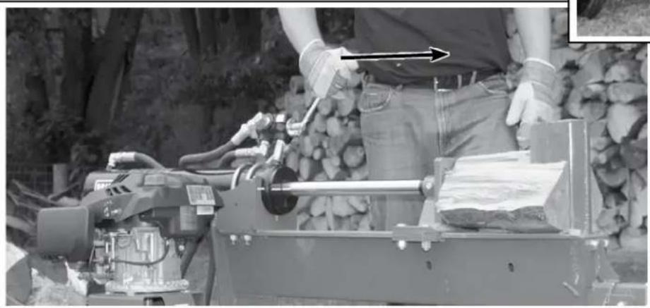
natural_image
Person operating a machine tool in a rocky outdoor setting, with no visible text or symbols.Move lever towards the wood to advance the cylinder rod
Fig. 10 STARTING
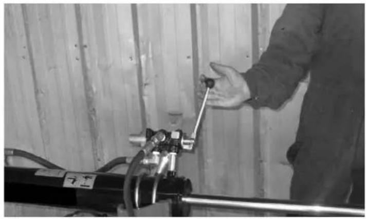
2. Stopping:
a. Retract the rod all the way
b. Release the control lever to stop the wedge.
c. Slow engine RPM to low idle.
d. Stop engine:
5.0 HP GC160 / GC190 - push throttle down, all others switch off ignition switch.
3. Emergency Stopping:
Release control lever and stop engine if an emergency occurs. Correct emergency situation before starting engine and resuming work.
4. Log Placement:
a. Always grasp the log by the sides when placing in the splitter. This will minimize the chance of the operator getting their fingers or arm between the wedge and the log.
b. Always wear the appropriate safety gear when working around the machine. This includes but is not limited to:
- Hard hat for protection to the head.
• Face mask for protection to the face and eyes from flying chips.
• Heavy gloves for protection from slivers, chips and pinching. - Safety shoes with slip resistant soles for protection to the feet and toes from dropped logs and pieces of wood. Slip resistant soles reduce the change of slipping.
natural_image
Person adjusting a mechanical component in a wooden room (no visible text or symbols)Fig. 11 STOPPING
natural_image
Person standing beside a mechanical cart with visible components and a wooden block, outdoors on sandy ground (no text or symbols)Horizontal
natural_image
Black-and-white photo of a large agricultural machine with wheels and a mounted sensor, parked on sandy ground (no visible text or symbols)Vertical
Fig. 12 SPLITTING
5. Operating the Cradle:
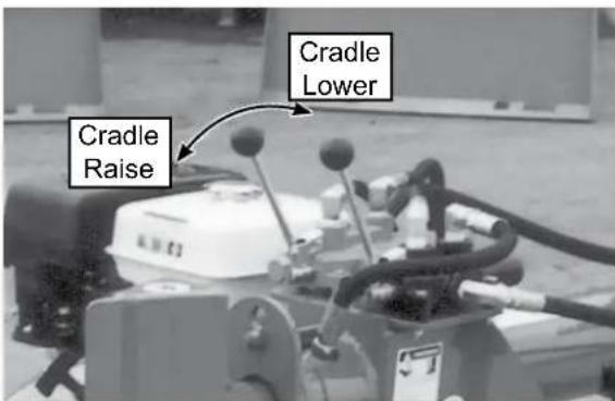
The WX950, WX960 and WX970 are designed with a lifting cradle to assist the operator in raising large, heavy wood or logs to the splitting bed on the machine.
The 3-position spring-loaded-to-center-neutral cradle lever controls the flow of oil to the cradle position cylinder.
- Move the lever toward the hitch and hold for the cylinder rod to extend and raise the cradle.
- Move the lever away from the hitch and hold to retract the cylinder rod and lower the cradle.
- Release the lever, it will return to its centered neutral position.
• The cylinder rod will stop moving.
Follow this procedure when operating these models:
a. Position Splitter at work site.
b. Start engine.
c. Lower cradle to the ground.
d. Move log on the cradle.
e. Use the control lever to raise the cradle until the bed is level.
f. Slide log over until it is centered on the splitting frame.
g. Move the wedge through the log.
h. Retract the wedge.
i. Remove the split pieces of wood from the machine.
j. Repeat with the next log.
text_image
Cradle Raise Cradle LowerCradle Control Lever
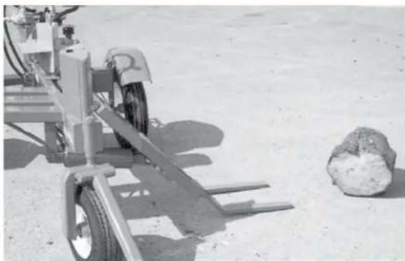
natural_image
Exterior view of a military vehicle on sandy terrain with a large rock nearby (no visible text or symbols)Cradle Lowered
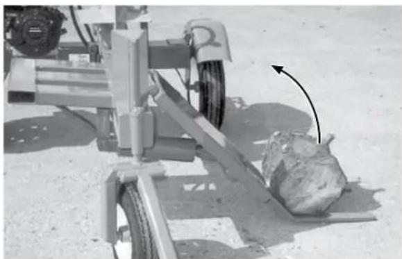
natural_image
Exterior view of a mechanical vehicle with a moving object on its side (no visible text or symbols)Cradle Loaded
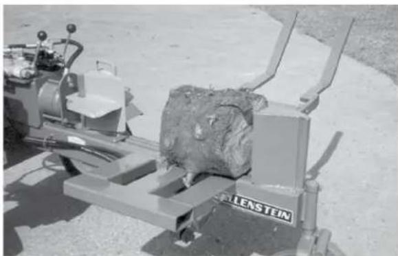
natural_image
Industrial machine with a large cylindrical component mounted on a base, no visible text or symbols on the equipment.Cradle Raised and Log Positioned
Fig. 13 LIFTING CRADLE
6. Converting for Vertical Splitting
Some models feature vertical splitting, these units are designed with a pivoting latching splitter frame that allows it to be used in the horizontal or vertical configuration.
- Before tilting the splitter frame, secure the splitter beam stabilizer: loosen the turn handle counter clockwise, lower the stabilizer and secure it with the turn handle.
- While standing beside the controls, release the splitter beam by pulling the spring loaded frame latch outward.
- At the same time grab the cylinder end and tip the splitter beam ass'y up towards the vertical position.
- Continue tipping, while placing your foot on the hydraulic tank / axle as a brace, until splitter is in the full vertical position.
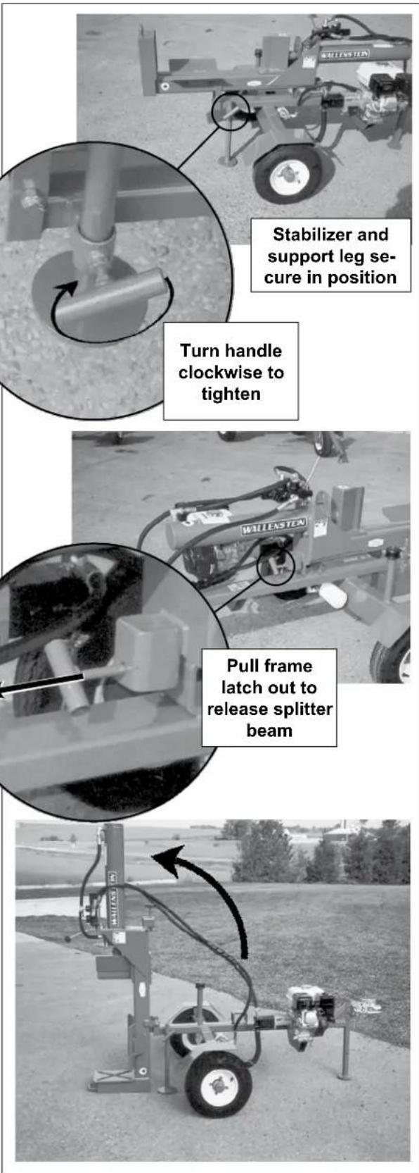
text_image
Stabilizer and support leg se- cure in position Turn handle clockwise to tighten Pull frame latch out to release splitter beamFig. 14 VERTICAL SPLITTING
7. Wedge Configuration:
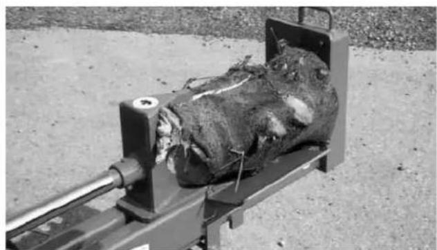
All Woodsplitters come from the factory equipped with a single blade wedge.
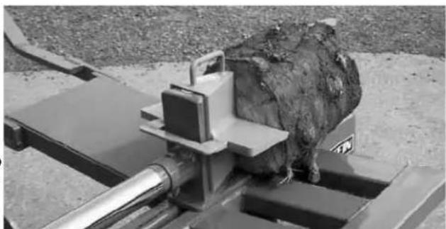
An optional 4 segment wedge is available for all splitter models (except the WX510).
Horizontal splitters require a 4 segment wedge which easily slips over the single blade.
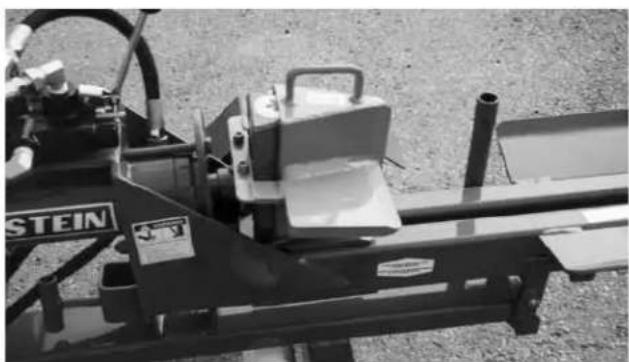
Vertical / Horizontal models require a 4-way wedge with a floating safety U-bolt retainer.
The 4 segment wedges can be used at any time with smaller logs or pieces of wood.
A detailed installation instruction sheet is included with each 4 way splitter kit.
See accessories page at the end of the manual for ordering details or for replacement parts, go to www.embmfg.com and click on "Parts and Manuals" to download the latest parts manual for you model, then call your dealer to order.
8. Operating Hints:
a. Hold the hydraulic lever in the wedge extend direction until the wedge reaches the base or the log/wood splits. Move it in the opposite direction to retract the wedge.
b. Always keep the working area neat and clean to prevent tripping. Pile the split and unsplit wood in piles close to the working area. Do not allow pieces to pile up and clutter the area. A cluttered working area can lead to tripping and accident. Do not take chances with safet
c. Do not place the splitter on muddy, icy, wet or cluttered surfaces. Each can lead to slipping or tripping and cause accidents.
d. When machine is new lubricate the plate under the wedge slider each time the machine is used to improve wear and reduce friction and/or binding. Once paint is worn off it will polish itself.
e. Ensure the back leg stand is secured before converting the frame into the vertical configuration.
natural_image
Black-and-white photo of a mechanical device with exposed internal material, mounted on a metal frame (no visible text or symbols)Single
natural_image
Black-and-white photo of a mounted machine tool with a textured object on top, set against a gravel background (no visible text or symbols)4-Way Slip-On
natural_image
Industrial machine labeled 'STEIN' with visible components and mounting base (no readable text beyond label)4-Way with U-Bolt Retainer
Fig. 15 WEDGES
4.7 TRANSPORTING

TRANSPORT SAFETY
- Comply with state and local laws governing highway safety and movement of machinery on public roads.
- The use of flashing amber lights is acceptable in most localities. However, some localities prohibit their use. Local laws should be checked for all highway lighting and marking requirements.
- At all times, when driving the tractor and equipment on the road or highway under 20 mph (32 kph) use flashing amber warning lights and a slow moving vehicle (SMV) identification emblem. Do not exceed 20 mph (32 kph) Reduce speed on rough roads and surfaces.
-
Plan your route to avoid heavy traffic.
-
Always install transport locks, pins or brackets before transporting.
- Do not drink and drive.
- Be a safe and courteous driver. Always yield to oncoming traffic in all situations, including narrow bridges, intersections, etc. Watch for traffic when operating near or crossing roadways.
- Never allow riders on either tractor or machine.
- When towing 3 wheel models always elevate the support wheel.
- Inspect rims for dents or damage, check wheel lugs and tighten if required.
When transporting the machine, review and follow these instructions:
- Be sure all bystanders are clear of the machine.
- Be sure that the machine is securely attached to the tractor or truck and retainer pins are installed through the drawbar pin or ball hitch coupler.
- Attach the safety chain securely to the tow frame to prevent unexpected separation. Cross the chains when attaching to the toe vehicle.
-
Ensure the frame lock pin is fully engaged on the pivoting frame models.
-
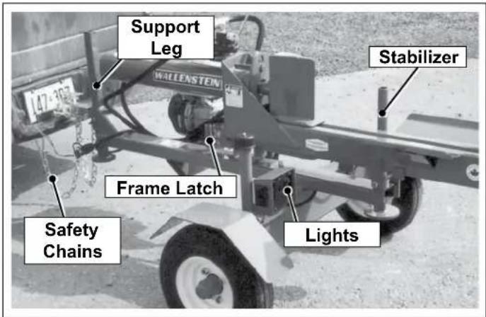
Depending on your model, raise and secure the support leg stand (all two wheel models), the splitter beam stabilizer (horizontal/vertical splitter models) and support wheel (three wheel models) before moving or transporting.
- Clean the SMV emblem, lights and reflectors and be sure they are working.
- Be sure you are in compliance with all applicable lighting and marking regulations when transporting. Check with your local authorities.
- Be sure your machine can clearly be seen by overtaking and oncoming traffic.
- Keep to the right and yield the right-of-way to allow faster traffic to pass. Drive on the road shoulder if permitted by law.
- Do not allow riders.
• Always use hazard flashers on the tractor when transporting unless prohibited by law.
text_image
Support Leg Stabilizer Frame Latch Safety Chains LightsFig. 16 TRANSPORTING
4.7.1 THREE WHEEL
When towing models WX950, WX960 and WX970 splitters, ensure you tow in the elevated position to avoid damage to the support wheel and tow vehicle. Follow these steps :
- Be sure all bystanders are clear of the machine.
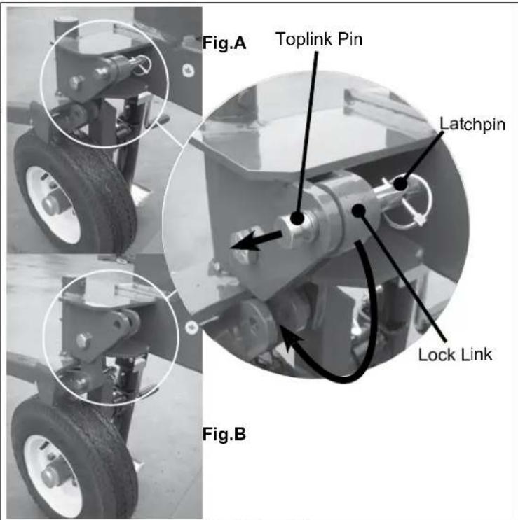
- Locate the lock link just behind the support wheel pivot as shown in Fig.A
- Remove the latchpin from the toplink pin and remove it from the lock link. The lock link will come free.
- Position the lock link into the lower locking tab on the wheel pivot, slide in the toplink pin, and insert the latchpin, as shown in Fig.B
text_image
Fig.A Toplink Pin Latchpin Lock Link Fig.BFig 17 Locking
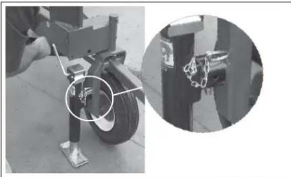
- The support wheel/hitch ass'y is now locked. Locate the swivel jack stored on the axle/tank ass'y. Remove the latch pin and move the swivel jack to the support wheel jack socket on the support wheel, insert the latchpin. See Fig 3
- When the swivel jack is secure, turn the jack handle clockwise to elevate the splitter hitch to match the tow vehicle hitch height.
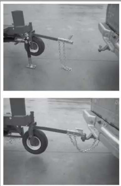
- Carefully back the tow vehicle up to the hitch, lower the splitter hitch and secure and latch the hitch to the tow vehicle.
- Cross and attach the tow chains to the tow vehicle, remove the swivel jack, and replace it in its storage area on the axle.
natural_image
Close-up of an aircraft landing gear with a close-up inset showing the joint detail (no text or symbols visible)Fig 18 Swivel Jack
natural_image
Two-panel black-and-white photo showing a small aircraft landing gear with chains attached, and a vehicle on the ground (no visible text or symbols)Fig 19
4.7.2 BALL & COUPLER
The Trailer Woodsplitter should always be located on a level, dry area that is free of debris and other foreign objects. When attaching the machine to a tow unit, follow this procedure:
- Make sure that all bystanders, especially small children, are clear of the working area.
- Make sure there is enough room and clearance to safely back up to the machine.
- Slowly back the tow vehicle until the coupler on the hitch and ball are aligned.
- Attach the ball hitch:
a. Lift the hitch and place the coupler over the ball on the hitch.
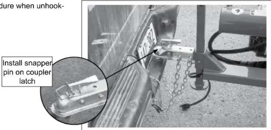
b. Flip the latch to lock the coupler around the ball and install.
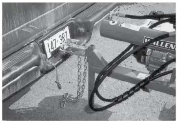
c. Install the snapper pin to secure the latch.
d. Pull out the snapper pin and pull up to place stand in its stowed position. Replace snapper pin.
-
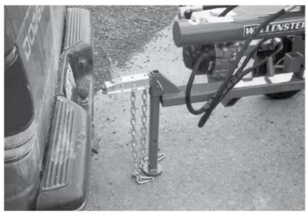
Attach the safety chain securely to the tow frame to prevent unexpected separation. Cross the chains when attaching to the toe vehicle
-
Reverse the above procedure when unhooking.
natural_image
Black-and-white photo of a vehicle with chain-link guardrail and a W. L. Enstei truck parked nearby (no visible text or symbols)Fig. 2 ALIGNED
natural_image
Close-up of a vehicle chassis with chains and attached equipment, no visible text or symbolsFig. 3 COUPLER
text_image
dure when unhook- Install snappen pin on coupler latchFig. 4 RETAINER/STAND/SAFETY CHAIN
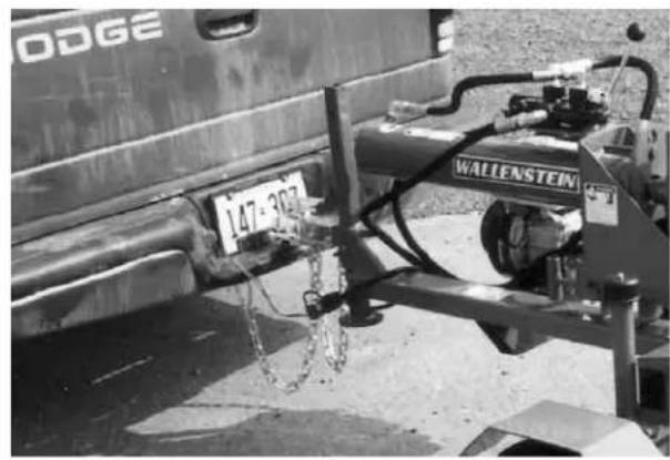
- If your splitter is out fitted with tail lights, ensure light wiring harness is connected to the tow vehicle.
- Route the harness and cables across the hitch to prevent snagging. Be sure to provide slack for turning.
- Reverse the above procedure when unhooking.
natural_image
Black-and-white photo of a car engine assembly with 'WALLENSTEIN' branding and number 147-302, no readable text or symbols beyond the label.Fig. 5 WIRING HARNESS
4.7.3 CLEVIS HITCH:
- Make sure that all bystanders, especially small children, are clear of the working area.
- Make sure there is enough room and clearance to safely back up to the machine.
- Slowly back the tow vehicle until the clevis on the hitch and tow vehicle are aligned.
- Attach the ball hitch:
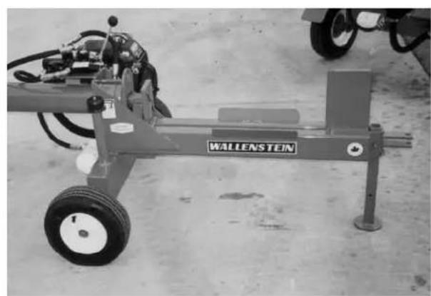
a. Install the drawbar pin through the hitch.
b. Install the snapper pin through the drawbar pin.
c. Attach the safety chain between the hitch and drawbar cage.
d. Pull out the snapper pin and pull up to place stand in its stowed position. Replace snapper pin.
- Attach the safety chain securely to the tow frame to prevent unexpected separation. Cross the chains when attaching to the toe vehicle
- Reverse the above procedure when unhooking.
natural_image
Mechanical testing machine labeled 'WALLENSTEIN' with wheels and components (no readable text beyond label)Fig. 6 CLEVIS HITCH
4.8 STORAGE

STORAGE SAFETY
- Store the unit in an area away from human activity.
- Do not permit children to play on or around the stored machine.
- Store the unit in a dry, level area. Support the frame with planks if required.
After the season's use, the machine should be thoroughly inspected and prepared for storage. Repair or replace any worn or damaged components to prevent any unnecessary down time at the start of next season. To insure a long, trouble free life, this procedure should be followed when preparing the unit for storage:
- Clear the area of bystanders, especially small children.
- Fully retract the cylinder rod.
- Thoroughly wash the machine using a pressure washer to remove all dirt, mud, debris and residue.
- Inspect the wedge, cylinder rod and wear plates for damage or entangled material. Repair or replace damaged parts. Remove all entangled material.
- Touch up all paint nicks and scratches to prevent rusting.
- Turn fuel valve OFF.
- Select an area that is dry, level and free of debris.
- Unhook from tractor or tow unit.
- If the machine cannot be placed inside, cover with a waterproof tarpaulin and tie securely in place.
- Store the machine in an area away from human activity.
- Do not allow children to play on or around the stored machine.
natural_image
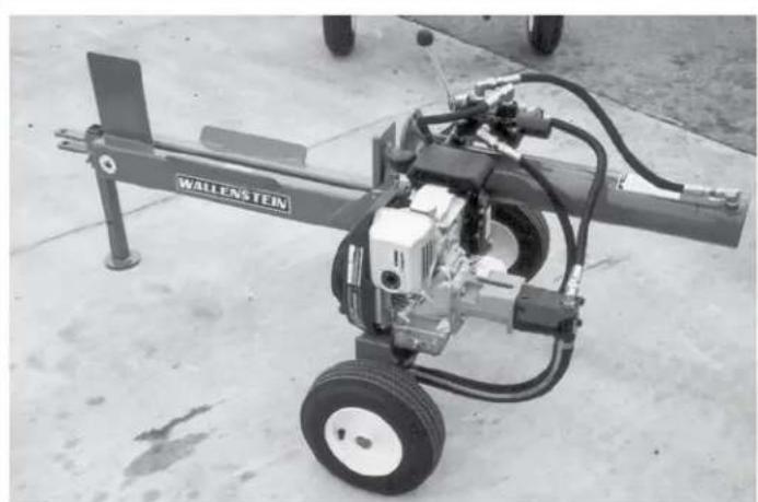
Industrial welding machine with a wallenstein brand label, mounted on a concrete ground (no visible text or symbols beyond branding)WX510
natural_image
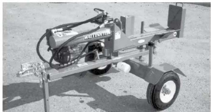
Exterior view of a metal industrial machine with wheels and a water spray bottle (no visible text or symbols)WX540
natural_image
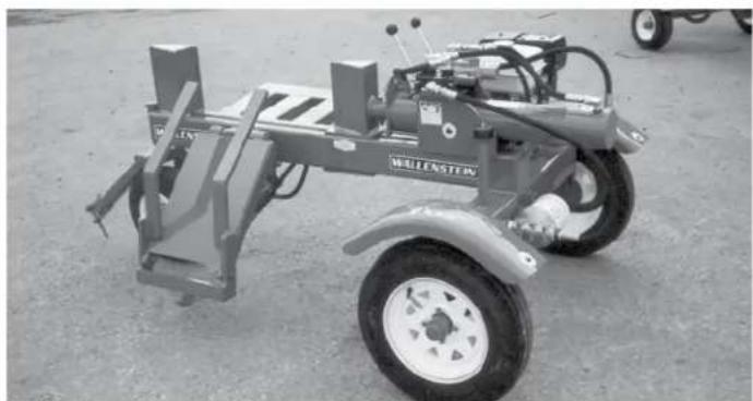
Exterior view of a wheeled agricultural machine with a large wheel and attached frame (no visible text or symbols)WX950
Fig. 20 STORED
5 SERVICE AND MAINTENANCE

MAINTENANCE SAFETY
- Follow ALL the operating, maintenance and safety information in the manual.
- Support the machine with blocks or safety stands when working beneath it.
-
Follow good shop practices.
-
Keep service area clean and dry.
- Be sure electrical outlets and tools are properly grounded.
-
Use adequate light for the job at hand.
-
Make sure there is plenty of ventilation. Never operate the engine of the towing vehicle in a closed building. The exhaust fumes may cause asphyxiation.
- Use only tools, jacks and hoists of sufficient capacity for the job.
- Make sure all guards are in place and properly secured when maintenance work is completed.
- Keep hands, feet, hair and clothing away from moving or rotating parts.
- Clear the area of bystanders, especially small children, when carrying out any maintenance and repairs or making any adjustments.
5.1 SERVICE
5.1.1 FLUIDS AND LUBRICANTS
1. Engine Oil:
Refer to the engine manufacturer's manual for maintenance and service information
2. Grease:
Use an SAE multi-purpose high temperature grease with extreme pressure (EP) performance. Also acceptable is an SAE multipurpose lithium base grease.
3. Engine Gasoline:
Use a standard automotive unleaded gasoline for all operating conditions.
Fuel tank capacity:
5.0 HP Honda GC160 1.8 L
5.5 HP Honda GX160 3.6 L
6.0 HP Honda GC190 1.8 L
6.5 HP Honda GX200 3.6 L
9.0 HP Honda GX270 6.0 L
4. Hydraulic Fluid Capacities:
Use a Dexron 3 Automatic Transmission Fluid.
Model Capacity
WX510, 515, 520 11 litres
WX530, 540, 630, 640 13 litres
WX610, 615, 620 11 litres
WX910 16 litres
WX950 20 litres
WX980 17 litres
WX920, 930, 960, 970 20 litres
5. Storing Lubricants:
Your machine can operate at top efficiency only if clean lubricants are used. Use clean containers to handle all lubricants. Store them in an area protected from dust, moisture and other contaminants.
5.1.2 GREASING
Use the Maintenance Checklist provided to keep a record of all scheduled maintenance.
- Use a hand-held grease gun for all greasing.
- Wipe grease fitting with a clean cloth before greasing to avoid injecting dirt and grit.
- Replace and repair broken fittings immediately.
- If fittings will not take grease, remove and clean thoroughly. Also clean lubricant passage. Replace fitting if necessary.
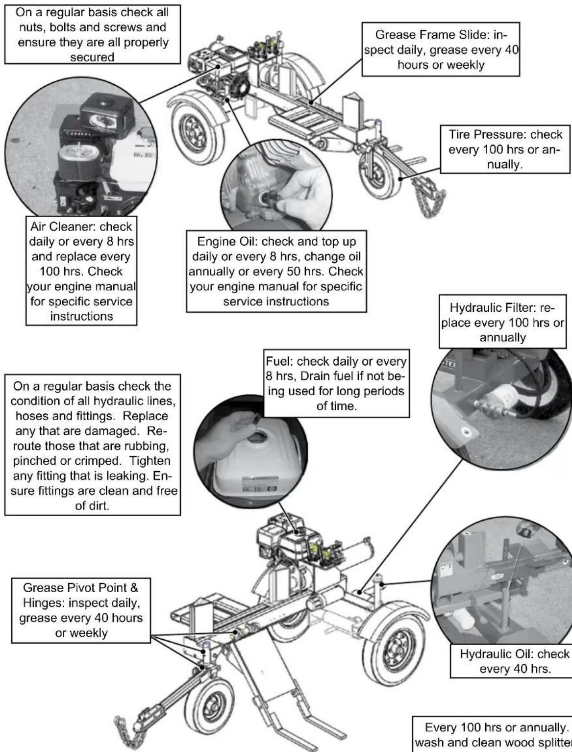
5.1.3 SERVICE ILLUSTRATION
See Service Record Chart
This illustration shows the general location of service points for all models in this manual.
Refer to your engine instruction manual for specific maintenance instructions / requirements
text_image
On a regular basis check all nuts, bolts and screws and ensure they are all properly secured Air Cleaner: check daily or every 8 hrs and replace every 100 hrs. Check your engine manual for specific service instructions Grease Frame Slide: inspect daily, grease every 40 hours or weekly Engine Oil: check and top up daily or every 8 hrs, change oil annually or every 50 hrs. Check your engine manual for specific service instructions Tire Pressure: check every 100 hrs or annually. Hydraulic Filter: replace every 100 hrs or annually Fuel: check daily or every 8 hrs, Drain fuel if not being used for long periods of time. On a regular basis check the condition of all hydraulic lines, hoses and fittings. Replace any that are damaged. Re-route those that are rubbing, pinched or crimped. Tighten any fitting that is leaking. Ensure fittings are clean and free of dirt. Grease Pivot Point & Hinges: inspect daily, grease every 40 hours or weekly Hydraulic Oil: check every 40 hrs. Every 100 hrs or annually. wash and clean wood splitterFig. 21 SERVICE
Every 100 hrs or annually. wash and clean wood splitter, remove entangled material, wood chips, small debris
5.1.4 SERVICE RECORD CHART
See Lubrication and Maintenance sections for details of service. Copy this page to continue record.
Refer to your engine instruction manual for specific maintenance instructions / requirements
| 8 Hours or Daily | 40 Hours or Weekly | 50 Hours or Annually | 100 Hours or Annually | |||||||||
| Check Check Check Check Check Check Change Grease Check Change Replace Clean | ||||||||||||
| Hydraulic hoses, fittings, frame slide | Secure fasteners | Engine Oil Level | Fuel Level | Air Cleaner | Hydraulic Oil Level | Engine Oil | Grease Frame Slide, Hinges, Pivot Points | Tire Pressure | Hydraulic Oil Filter | Engine Air Cleaner | Clean Machine | |
| ServicerHrs | ||||||||||||
| 24 Hours or 3 Hours per hour | ||||||||||||
5.2 MAINTENANCE
By following a careful service and maintenance program for your machine, you will enjoy many years of trouble-free operation. Review your engines instruction manual for specific instructions / requirements
5.2.1 CLEANING AIR CLEANER
- Review your engines instruction manual for specific instructions / requirements
- Place all controls in neutral, stop and disable engine before maintaining.
- Remove cover over air cleaner.
- Remove the filter from the engine.
- Use an air hose to blow the dust and debris out of the filter.
- Install filter.
- Install and secure the cover.
5.2.2 CHANGING ENGINE OIL
- Review your engines instruction manual for specific instructions / requirements
- Place all controls in neutral, stop and disable engine before maintaining.
- Allow the engine to cool before changing the oil. Hot oil can cause burns if it contacts exposed skin. It is best to change oil while the engine is warm to keep the contaminants in suspension.
- Place a pan under the drain plug.
- Remove the drain plug and allow the oil to drain for 10 minutes.
- Install and tighten the drain plug.
- Place the used oil in an approved container and dispose of in a environmentally safe manner.
- Fill the crankcase with the specified oil. Review your engines instruction manual for specific instructions / requirements
- Run the engine for 1-2 minutes and check for oil leaks.
- If leaks are found around the drain plug or filter, tighten slightly. Repeat step 9.
- Check engine oil level. Top up as required.
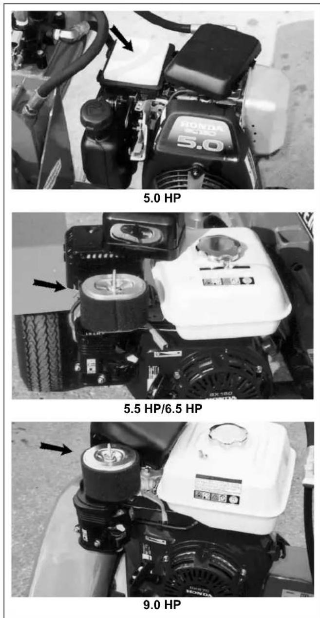
Fig. 22 AIR CLEANER
5.2.3 HYDRAULIC SYSTEM OIL FILTER
- Review the Operator's Manual for the splitter.
- Place all controls in neutral, stop and disable engine before maintaining.
- Allow the machine to cool before changing the filter. Hot oil can cause burns if it contacts exposed skin.
- Place a pan under the filter head.
- Remove the oil filter, grasp the filter firmly and turn counter-clockwise. An oil filter wrench may be used if required.
- Find and inspect the "O" ring, replace if damaged or worn. Apply a light coat of oil to the "O" ring.
- Install the replacement filter, turn clockwise. Snug up by hand and then tighten 1/2 turn.
- Run the machine for 1-2 minutes while operating cylinder and check filter head for oil leaks.
- If leaks are found around the filter, tighten slightly. If leaks persist repeat steps 6-9.
- Check hydraulic reservoir oil level. Top up as required.
- Place the spilled oil in an approved container and dispose of in a environmentally safe manner.
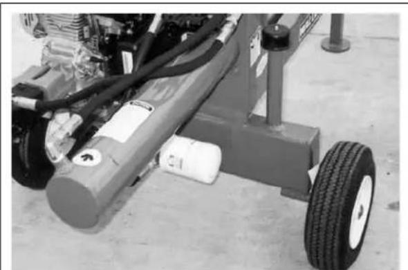
natural_image
Close-up of a mechanical lift or support structure with visible hoses and wheels, no text or symbols present.WX510
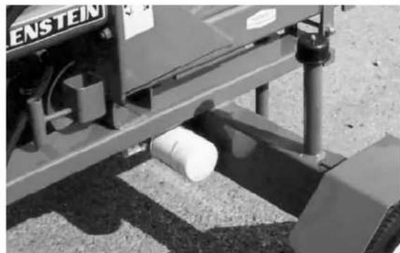
natural_image
Mechanical testing setup with a white cylindrical component mounted on a platform, no visible text or symbolsWX540
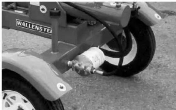
natural_image
Close-up of a car's wheel assembly with visible components and a 'WALLENSTEI' label (no other text or symbols)WX950
Fig. 23 HYDRAULIC SYSTEM FILTER
6 TROUBLE SHOOTING
The Wallenstein Trailer Woodsplitter uses hydraulic power to move a hydraulic cylinder rod to split wood or logs. It is a simple and reliable system that requires minimal maintenance.
In the following chart, we have listed many of the problems, causes and solutions to the problems that you may encounter.
If you encounter a problem that is difficult to solve, even after having read through this trouble shooting section, please call your local dealer, distributor or Wallenstein. Before you call, please have this Operator's Manual and the serial number from your Woodsplitter ready.
6.1 TROUBLE SHOOTING CHART

Always wear the appropriate safety gear when trouble shooting, performing maintenance or working around the he. This includes but is not limited to:
- Hard hat for protection to the head. - Face mask for protection to the face and eyes.
- Heavy gloves for hand protection. - Safety shoes with slip resistant soles and steel toes
| PROBLEM | CAUSE | SOLUTION | CAUTION | |
| Cylinder rod moves slowly or doesn't move. | No pressurized hydraulic oil. | Oil filter plugged. Change filter. |  | Ensure machine is off and cooled down. |
| No pressurized hydraulic oil | Low hydraulic oil level, top up |  | Ensure machine is off and cooled down | |
| Wood jammed around wedge. | Shut machine off and safely remove wood. |  | Ensure machine is off | |
| Not enough pressure. | Call technician, system relief setting may be low (below 2750 psi). |  | Ensure machine is off and call hydraulic technician. | |
| Low engine speed. | Check that choke is off, check throttle is set to maximum. | |||
| Control handle doesn't go to neutral after rod is fully retracted. | Detent set too tight. | Call technician, adjustment required with detent on valve. |  | Ensure machine is off and call hydraulic technician. |
| Hydraulic fluid too cold. | Allow machine to warm up. |  | ||
| Hydraulic fluid is too old or contaminated. | Change hydraulic fluid and filter |  | Ensure machine is off and cooled down. | |
| Control handle goes to neutral before rod is fully retracted. | Detent set too loose. | Call technician, adjustment required with detent on valve. |  | Ensure machine is off and call hydraulic technician. |
| Control handle does't go to neutral when released. | Control may be damaged. | Call technician, control may need service or be replaced. |  | Ensure machine is off and call hydraulic technician. |
| Cylinder stops on contact with wood. | Second stage on pump not functioning. | Call technician, pump may need service or be replaced. |  | Ensure machine is off and call hydraulic technician. |
| Wedge jumps. | Wedge frame jamming. | Lubricate wedge frame wear plates. | Ens  | chine is off. |
| Leaking hydraulic hose. | Hose worn or damaged. | Replace hose. |  | Ensure machine is off and cooled down. |
| Leaking cylinder. Seals worn. | Call technician, seal replacement may be required. |  | Ensure machine is off and call hydraulic technician. | |
| Engine related issues. | Refer to your engine instruction manual for specific trouble shooting instructions / requirements. | |||
7 SPECIFICATIONS
7.1 MECHANICAL
| 500 SERIES 5 & 5.5 HP WOODSPLITTERS | ||||||
| MODEL | WX510 | WX515 | WX520 | WX520T | WX530 | WX540 |
| MOUNTING | TRAILER MOUNTED | |||||
| HONDA ENGINE MODEL | GC160 | GC160 | GX160 | GX160 | GC160 | GX160 |
| HORSEPOWER | 5 HP | 5 HP | 5.5 HP | 5.5 HP | 5 HP | 5.5 HP |
| CYLINDER DIAMETER | 4" | |||||
| CYLINDER STROKE | 24" | |||||
| SPLITTING FORCE | 20 TON | |||||
| CYCLE TIME | 14 SEC | |||||
| STANDARD VALVE TYPE | 3-POS. SPRNG LOADED TO CENTER - AUTO RETURN DETENT | |||||
| HYDRAULIC PUMP TYPE | 2 STAGE | |||||
| HYDRAULIC PUMP FLOW | 11 GPM | |||||
| BED HEIGHT | 16" | 19" | 19" | 28" | 24" | 24" |
| WEDGE HEIGHT | 9" | |||||
| TIRE SIZE | 4.10 X 6 | 4.80 X 7 | 4.80 X 8 | 4.80 X 8 | 4.80 X 8 | 4.80 X 8 |
| TIRE TYPE | OFF ROAD | HIGHWAY | HIGHWAY | HIGHWAY | HIGHWAY | HIGHWAY |
| SAFETY CHAINS | N/A | STANDARD | STANDARD | STANDARD | STANDARD | STANDARD |
| BALL HITCH SIZE | CLEVIS HITCH | 2" | ||||
| TRAILER LIGHT PACKAGE | N/A | FACTORY OPTION | ||||
| SPLITTER ORIENTATION | HORIZONTAL | HORIZONTAL | HORIZONTAL | HORIZONTAL | HORIZ & VERT | HORIZ & VERT |
| OPTIONAL 4-WAY SPLITTING WEDGE | N/A | #4110 | #4110 | #4110 | #4120 | #4120 |
| SHIPPING WEIGHT | 299 LB | 360 LB | 365 LB | 375 LB | 470 LB | 470 LB |
| DIMENSIONS (LxWxH) (INCHES) | 68 x 38 x 32 | 72 x 42 x 36 | 72 x 42 x 36 | 72 x42 x45 | 80 x 48 x 40 | 80 x 48 x 40 |
| 600 SERIES 6 & 6.5 HP WOODSPLITTERS | |||||
| MODEL | WX615 WX620 WX620T WX630 WX640 | ||||
| MOUNTING | TRAILER MOUNTED | ||||
| HONDA ENGINE MODEL GC190 GX200 | GX200 GC190 GX200 | ||||
| HORSEPOWER 6 HP 6.5 HP 6.5 HP 6 HP | 6.5 HP | ||||
| CYLINDER DIAMETER | 4.5" | ||||
| CYLINDER STROKE | 24" | ||||
| SPLITTING FORCE | 25 TON | ||||
| CYCLE TIME | 14 SEC | ||||
| STANDARD VALVE TYPE | 3-POS. SPRNG LOADED TO CENTER - AUTO RETURN DETENT | ||||
| HYDRAULIC PUMP TYPE | 2 STAGE | ||||
| HYDRAULIC PUMP FLOW | 11 GPM | ||||
| BED HEIGHT 21" 21" 30" 27" 27" | |||||
| WEDGE HEIGHT | 10" | ||||
| TIRE SIZE | 4.80 X 8 | ||||
| TIRE TYPE | HIGHWAY | ||||
| SAFETY CHAINS | STANDARD | ||||
| BALL HITCH SIZE | 2" | ||||
| TRAILER LIGHT PACKAGE | FACTORY OPTION | ||||
| SPLITTER ORIENTATION HORIZONTAL | HORIZONTAL HORIZONTAL HORIZ & VERT HORIZ & VERT | ||||
| OPTIONAL 4-WAY SPLITTING WEDGE | #4140 | #4140 | #4140 | #4130 | #4130 |
| SHIPPING WEIGHT | 475 LB | 480 LB | 488 LB | 525 LB | 530 LB |
| DIMENSIONS (LxWxH) (INCHES) | 78 x 40 x 42 | 78 x 40 x 42 | 86 x 49 x 42 | 80 x48 x40 | 80 x 48 x 40 |
| 900 SERIES 9 HP WOODSPLITTERS | ||||||||
| WX910 | WX910T | WX920 | WX930 | WX950 | WX960 | WX970 | WX980 | |
| MOUNTING | TRAILER MOUNTED | |||||||
| ENGINE MODEL | GX270 | |||||||
| HORSEPOWER | 9 HP | |||||||
| CYLINDER DIAMETER | 4 1/2" | 5" | ||||||
| CYLINDER STROKE | 24" | 24" | 36" | 48" | 24" | 36" | 48" | 24" |
| SPLITTING FORCE | 25 TON | 31 TON | ||||||
| CYCLE TIME | APPROXIMATE 14 SECONDS | |||||||
| STANDARD VALVE TYPE | 3-POS. SPRNG LOADED TO CENTER - AUTO RETURN DETENT | |||||||
| CRADLE CONTROL | N/A | N/A | N/A | N/A | 3-POS. SPRNG LOADED TO CENTER | 3-POS. SPRNG LOADED TO CENTER | 3-POS. SPRNG LOADED TO CENTER | N/A |
| HYDRAULIC PUMP TYPE | TWO STAGE | |||||||
| HYDRAULIC PUMP FLOW | 16 GPM | |||||||
| BED HEIGHT | 21" | 28.5" | 21" | 21" | 25" | 25" | 25" | 26" |
| WEDGE HEIGHT | 10" | |||||||
| TIRE SIZE | 5.30 X 12 | |||||||
| SAFETY CHAINS | STANDARD | |||||||
| BALL HITCH SIZE | 2" | |||||||
| TRAILER LIGHT PACKAGE | FACTORY OPTION | |||||||
| SPLITTER ORIENTATION | HORIZONTAL | HORIZ & VERT | ||||||
| LOG LIFTING CRADLE | N/A | N/A | N/A | N/A | STANDARD | STANDARD | STANDARD | N/A |
| 4-WAY SPLITTING WEDGE | #W4140 | #4140 | #4130 | #4130 | #4130 | #4130 | #4130 | #4130 |
| SHIPPING WEIGHT | 510 LB | 525 LB | 720 LB | 865 LB | 785 LB | 990 LB | 1135 LB | 635 LB |
| DIMENSIONS (LxWxH) (INCHES) | 73 x 63 x 35 | 78 x 50 x 42 | 97 x 63 x 35 | 121 x 63 x 35 | 81 x 63 x 38 | 107 x 63 x 38 | 130 x 63 x 38 | 80 x 50 x 42 |
SPECIFICATIONS ARE SUBJECT TO CHANGE WITHOUT NOTICE
7.2 HYDRAULIC FITTING TORQUE
Tightening Flare Type Tube Fittings \*
- Check flare and flare seat for defects that might cause leakage.
- Align tube with fitting before tightening.
- Lubricate connection and hand tighten swivel nut until snug.
- To prevent twisting the tube(s), use two wrenches. Place one wrench on the connector body and with the second tighten the swivel nut to the torque shown.
| HYDRAULIC FITTING TORQUE | |||||
| Tube Size OD | Nut Size Across Flats | Torque Value* | Recommended Turns To Tighten (After Finger Tightening) | ||
| (in.) (in.) | (N.m) (lb-ft) (Flats) (Turn) | ||||
| 3/16 7/1 | 6 8 6 1 1/6 | ||||
| 1/4 9/16 | 12 | 9 1 1/6 | |||
| 5/16 5/8 | 16 | 12 | 1 1/6 | ||
| 3/8 11/1 | 6 24 | 18 | 1 1/6 | ||
| 1/2 | 7/8 46 | 34 | 1 1/6 | ||
| 5/8 | 1 | 62 | 46 | 1 | 1/6 |
| 3/4 1-1/4 | 102 | 75 | 3/4 | 1/8 | |
| 7/8 1-3/8 | 122 | 90 | 3/4 | 1/8 | |
*The torque values shown are based on lubricated connections as in reassembly.
7.3 BOLT TORQUE
CHECKING BOLT TORQUE
| ENGLISH TORQUE SPECIFICATIONS | ||||||
| Bolt Diamter "A" | Bolt Torque* | |||||
| SAE 2 (N.m) (lb-ft) | SAE 5 (N.m) (lb-ft) | SAE 8 (N.m) (lb-ft) | ||||
| 1/4" | 8 | 6 | 12 | 9 | 17 | 12 |
| 5/16" | 13 | 10 | 25 | 19 | 36 | 27 |
| 3/8" | 27 | 20 | 45 | 33 | 63 | 45 |
| 7/16" | 41 | 30 | 72 | 53 | 100 | 75 |
| 1/2" | 61 | 45 | 110 | 80 | 155 | 115 |
| 9/16" | 95 | 60 | 155 | 115 | 220 | 165 |
| 5/8" | 128 | 95 | 215 | 160 | 305 | 220 |
| 3/4" | 225 | 165 | 390 | 290 | 540 | 400 |
| 7/8" | 230 | 170 | 570 | 420 | 880 | 650 |
| 1" | 345 | 225 | 850 | 630 | 1320 | 970 |
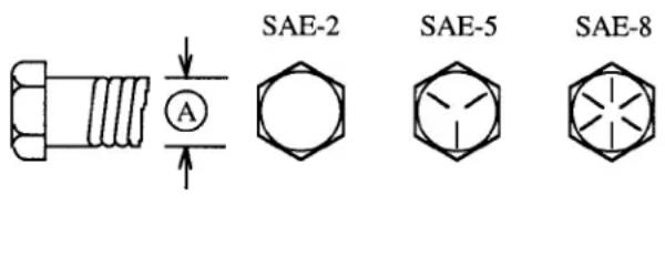
text_image
SAE-2 SAE-5 SAE-8| METRIC TORQUE SPECIFICATIONS | ||||
| Bolt Diameter"A" | Bolt Torque* | |||
| 8.8(N.m) (lb-ft) | 10.9(N.m) (lb-ft) | |||
| M3 | 0.5 | 0.4 | 1.8 | 1.3 |
| M4 | 3 2.2 | 4.5 | 3.3 | |
| M5 | 6 | 4 | 9 | 7 |
| M6 | 10 7 15 11 | |||
| M8 | 25 18 85 | 26 | ||
| M10 50 37 70 52 | ||||
| M12 90 66 | 125 | 92 | ||
| M14 | 140 | 103 | 200 | 148 |
| M16 | 225 | 166 | 310 | 229 |
| M20 | 435 | 321 | 610 | 450 |
| M24 | 750 | 553 10 | 50 774 | |
| M30 | 1495 | 1103 | 2100 | 1550 |
| M36 | 2600 | 1917 | 3675 | 2710 |
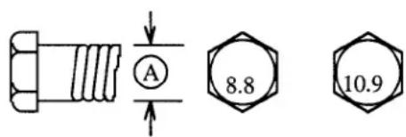
text_image
A 8.8 10.9Torque figures indicated above are valid for non-greased or non-oiled threads and heads unless otherwise specified. Therefore, do not grease or oil bolts or capscrews unless otherwise specified in this manual. When using locking elements, increase torque values by 5%.
* Torque value for bolts and capscrews are identified by their head markings.
8 ACCESSORIES
Call your dealer for pricing and availability
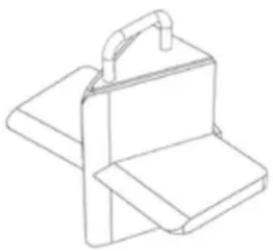 #W4110 #W4110 | #W4110 4 WAY SPLITTING WEDGEFor models:WX515, WX520, WX520Teasy to install, slip over single stationary wedge and you're ready to go!4 way splitting wedge, Boost your productivity and make quick work out of chunks by splitting into four pieces at once. This is an ideal way to save time |
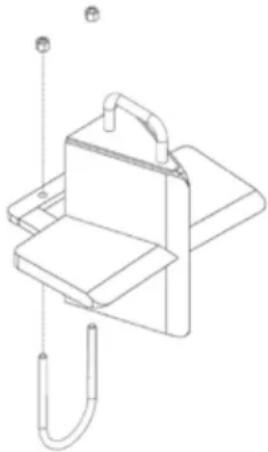 #W4120 #W4120 | #W4120 4 WAY SPLITTING WEDGEw/ safety boltFor models:WX530, WX540easy to install, slip over and attach safety "u" bolt4 way splitting wedge, Boost your productivity and make quick work out of chunks by splitting into four pieces at once. This is an ideal way to save time |
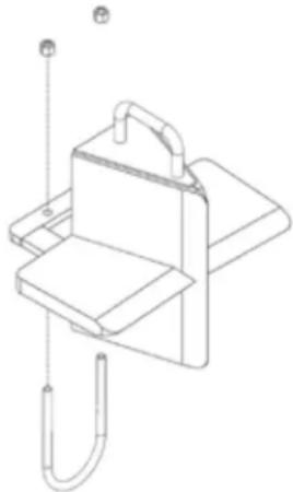 #W4130 #W4130 | #W4130 4 WAY SPLITTING WEDGEw/ safety boltFor models:WX630, WX640, WX920, WX930, WX950, WX960, WX970, WX980easy to install, slip over and attach safety "u" bolt4 way splitting wedge, Boost your productivity and make quick work out of chunks by splitting into four pieces at once. This is an ideal way to save time |
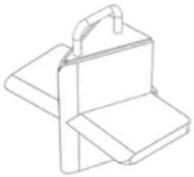 #W4140 #W4140 | #W4140 4 WAY SPLITTING WEDGEFor models:WX615, WX620, WX620Teasy to install, slip over single stationary wedge and you're ready to go!4 way splitting wedge, Boost your productivity and make quick work out of chunks by splitting into four pieces at once. This is an ideal way to save time |
INDEX
A
ACCESSORIES 44
AIR CLEANER 39
B
BOLT TORQUE 43
C
CHOKE 23
CLEVIS 34
CONTROLS 23
CONVERTING FOR VERTICAL SPLITTING ...29
CRADLE POSITION CONTROL LEVER .....24
D
DELIVERY INSPECTION REPORT ....4
E
EMERGENCY STOPPING 27
ENGINE OIL 39
F
FIELD OPERATION 25
FILTER 40
FLUIDS 36
FUEL SHUT-OFF VALVES 23
G
GAS ENGINE 23
GREASING 36
H
HYDRAULIC CONTROLS 24
HYDRAULIC FITTING 43
|
IGNITION SWITCH 23
INTRODUCTION 6
L
LOG PLACEMENT 27
LUBRICANTS 36
M
MACHINE BREAK-IN 22
MAINTENANCE 36
O
OPERATING HINTS 30
TROUBLE SHOOTING CHART ....41
V
VERTICAL SPLITTING 29