
CV620-IPW - Security Camera Marshall Electronics - Free user manual and instructions
Find the device manual for free CV620-IPW Marshall Electronics in PDF.


| Product Type | Full HD PTZ IP Security Camera |
| Dimensions (L x W x H) | 174 x 186.2 x 185.5 mm |
| Weight (camera only) | 1.8 kg |
| Weight (with mounting hardware) | Approx. 2.5 kg |
| Power Supply | DC 12V input or PoE (Power over Ethernet) |
| Power Consumption | Not specified in manual; typical PTZ camera ~15-20W |
| Video Outputs | HDMI, 3G-SDI, IP (RTSP/RTMP) |
| Resolution / Frame Rate | Up to 1080p at 60 fps (also 1080i, 720p) |
| Pan / Tilt Range | Pan: ±170°, Tilt: -30° to +90° |
| Zoom | Optical zoom (exact magnification not specified; typical 20x) |
| Network Protocols | DHCP, IP, RTSP, RTMP, HTTP |
| Control Interfaces | RS-232, RS-422, IR remote, Web GUI |
| Audio Input | Line-in or Mic-in (3.5mm audio jack) |
| Memory / Presets | Up to 128 presets via VISCA commands |
| Mounting | Desk or ceiling mount (with included metal plates) |
| Operating Environment | Indoor use only; avoid heat, water, and unstable surfaces |
| Cleaning | Unplug before cleaning; use a damp cloth; no liquid or aerosol cleaners |
| Safety Certifications | UL/CE approved hanger recommended; Class A FCC compliance |
| Spare Parts / Repairability | No user-serviceable parts; refer servicing to licensed personnel |
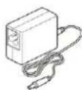
| Package Contents | Camera, power adapter, remote control, RS-422 connector, metal plates A & B, M3 screws |
Frequently Asked Questions - CV620-IPW Marshall Electronics
User questions about CV620-IPW Marshall Electronics
0 question about this device. Answer the ones you know or ask your own.
Ask a new question about this device
Download the instructions for your Security Camera in PDF format for free! Find your manual CV620-IPW - Marshall Electronics and take your electronic device back in hand. On this page are published all the documents necessary for the use of your device. CV620-IPW by Marshall Electronics.
USER MANUAL CV620-IPW Marshall Electronics
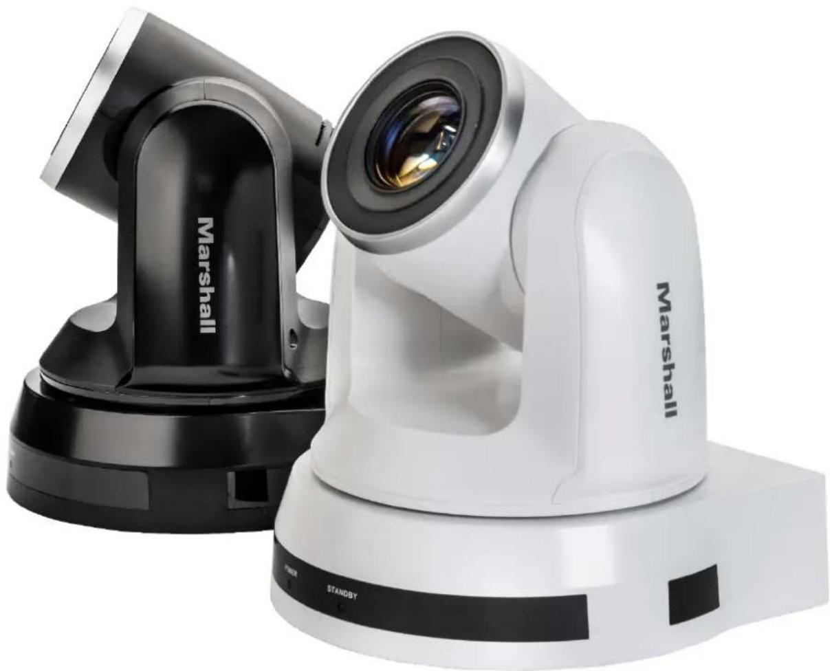
Full HD PTZ Conference IP Camera
natural_image
Exterior view of a white Marshall radar or camera with black and white components (no visible text or symbols on the device itself)User Manual
Table of Contents
Chapter 1. Safety Instructions....3
Chapter 2. Package Contents ....5
Chapter 3. Product Overview....6
3.1 Overview....6
3.2 Description of LED indicator....6
Chapter 4. Instruction for installation....7
4.1 Preparation before installation....7
4.2 Instruction for installation....7
4.3 Connecting devices 14
Chapter 5. Remote Control and Setting Menu .... 18
5.1 Functions of remote control....18
5.2 Setting Menu....19
Chapter 6. Descriptions of Major Functions ...... 25
6.1 I would like to switch to CV620-IPW....25
6.2 I would like to save the current lens position data 25
6.3 I would like to clear the saved position data 25
6.4 I would like to turn on the back light compensation function 25
6.5 I would like to adjust the shooting angle of the lens 25
6.6 I would like to zoom in/out images 25
6.7 I would like to adjust the focal length 25
6.8 I would like to adjust the AF speed....25
6.9 I would like to set the image mode....26
6.10 I would like to freeze images....26
6.11 I would like to rotate the image....26
6.12 I would like to change the camera direction....26
6.13 I would like to display the current status 26
6.14 I would like to reset to the default value....26
Chapter 7. Network Function Settings Description ......27
7.1 Web System Requirements....27
7.2 Online IP Camera 27
7.3 Web Page Function Description....29
Chapter 8. DIP switch setting ...... 36
8.1 DIP SWITCH....36
8.2 RS-422 Connection 37
Chapter 9. Troubleshooting ...... 39
Chapter 1. Safety Instructions
Please use the product following the safety instructions below:
1 Operation
1.1 Please use the product in the recommended operating environment.
1.2 Do not place Light Engine in tilted position.
1.3 Do not place the product on an unstable trolley, stand or table.
1.4 Do not use this product near water or source of heat.
1.5 Use attachments only as recommended.
1.6 Use the type of power source indicated on the HD Camera. If you are not sure of the type of power available, consult your dealer or local electricity company for advice.
1.7 Always take the following precautions when handling the plug. Failure to do so may result in sparks or fire.
■ Ensure the plug is free of dust before inserting it into a socket.
■ Ensure that the plug is inserted into the socket securely.
1.8 Do not overload wall sockets, extension cords or multi-way plug boards to avoid potential risks.
1.9 Do not block slots and openings in the case of this product as poor ventilation may lead to overheating of this product.
1.10 Except as specifically instructed in this User Manual, do not attempt to open or remove covers by yourself. It may expose you to electric shock or other hazards. Refer all servicing to licensed service personnel.
1.11 Unplug this product from the wall outlet and refer servicing to licensed service personnel when the following situations happen:
■ If the power cords are damaged or frayed.
■ If liquid is spilled into the HD Camera or the HD Camera has been exposed to rain or water.
2 Installation
2.1 For security considerations, please make sure the standard hanging rack you bought is in line with UL or CE safety approbations and installed by technician personnel approved by agents.
3 Storage
3.1 Do not place the HD Camera where the cord can be stepped on as this may result in fraying or damage to the lead or the plug.
3.2 Never push objects of any kind through cabinet slots. Never allow liquid of any kind to spill into the HD Camera.
3.3 Unplug this product during thunderstorms or if it is not going to be used for an extended period.
3.4 Do not place this product or accessories on top of vibrating equipment or heated objects.
4 Cleaning
4.1 Unplug all the cables before cleaning. Use a damp cloth for cleaning. Do not use liquid or aerosol cleaners.
5 Remote control (if the accessories are equipped with remote control)
5.1 Using an incorrect battery type in the remote control may result in breakdown. Follow local instructions on how to dispose of used batteries.
■ Precautions
Warning: To reduce the risk of fire or electric shock, do not expose this appliance to rain or moisture.
If HD Camera will not be used for an extended time, unplug it from the power socket.
 | Note |  | ||
| Risk of Electric ShockPlease do not open it by yourself. | ||||
| Caution: To reduce the risk of electric shock, do not remove cover (or back). No user-serviceable parts inside. Refer servicing to licensed service personnel. | ||||
 | This symbol indicates that this equipment may contain dangerous voltage which could cause electric shock. |  | This symbol indicates that there are important operating and maintenance instructions in this User Manual with this unit. | |
■ FCC Warning
This HD Camera has been tested and found to comply with the limits for a Class A digital device, pursuant to Article 15-J of FCC Rules. These limits are designed to provide reasonable protection against harmful interference in a commercial installation.
This digital apparatus does not exceed the Class A limits for radio noise emissions from digital apparatus as set out in the interference-causing equipment standard entitled "Digital Apparatus," ICES-003 of Industry Canada.
Operation of this equipment in a residential environment could cause radio interference.
Chapter 2. Package Contents
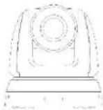
CV620-IPW
Power Cord
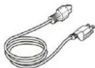
Appearance may vary depending on country/region
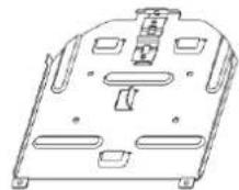
Metal Plate A
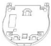
Instruction for installation
Power Adapter
Metal Plate B
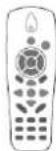
Remote Control
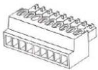
RS-422 Connector
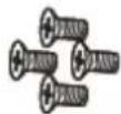
M3 Screws
Chapter 3. Product Overview
3.1 Overview
Front View  | 1. Camera lens |
| 2. Power LED indicator | |
| 3. Standby LED indicator | |
| 4. Audio In | |
| 5. USB port (for FW update) | |
Back View 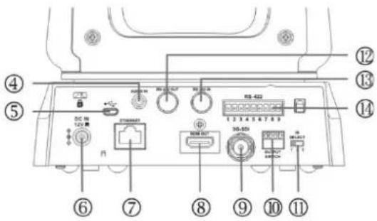 | 6. Power input |
| 7. Network port (supported for PoE) | |
| 8. HDMI Output | |
| 9. 3G-SDI | |
| 10. OUTPUT Switch | |
Bottom 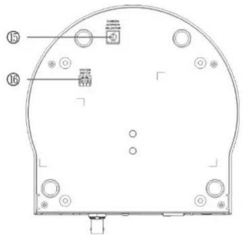 | 11. IR SELECT |
| 12.RS-232 output | |
| 13.RS-232 input | |
| 14.RS-422 Connection | |
| 15. Camera Address Selectors | |
| 16. SYSTEM Switch |
3.2 Description of LED indicator
| Status | Power | Standby |
| Startup in progress | Green light | Orange light |
| In use | Green light | No indicator |
| In standby mode | No indicator | Orange light |
| Signal from the remote control is received | Green light flickers; it flickers every 0.5 second | No indicator |
Chapter 4. Instruction for installation
4.1 Preparation before installation
Installation and connection of CV620-IPW HD camera requires special skills. To install by yourself, please follow necessary steps, ensure steady and tight installation of the device, and pay attention to your safety to avoid any accident.
4.1.1 Ensure the safety of the installation environment. Please do not install the device on unstable ceiling or in a place where the device is in danger of falling to avoid any accident.
4.1.2 Please check whether accessories in the box are complete or not. Please contact the supplier for any shortage, and make sure to keep the accessories in the box intact.
4.1.3 Please choose a proper place for installation of CV620-IPW in advance. Please determine an installation place according to the following requirements
4.1.1.1 Confirm the position for the object to be captured.
4.1.1.2 Confirm whether the CV620-IPW is set at a proper distance from other light sources.
4.2 Instruction for installation
4.2.1 I would like to install CV620-IPW on the desk
4.2.1.1 Precautions for installation
◆ Please install the machine on a flat desk
◆ Do not grab the camera head by hand when handling the device
◆ Do not rotate the camera head by hand. Improper rotation may result in breakdown of the camera

natural_image
Four hand-drawn diagrams showing a device being handled, with no text or symbols present.4.2.1.2 Installation steps
- Please adjust DIP switch at first prior to installation Note: Please refer to Chapter 8 DIP Switch Setting for the relevant descriptions on DIP switch.
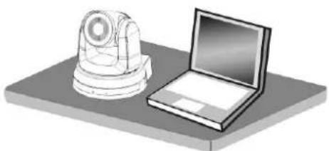
- Place the camera on a flat desk directly to ensure the normal vertical and horizontal operation of the machine
natural_image
Illustration of a laptop and a mechanical device on a flat base (no text or symbols)4.2.2 I would like to install CV620-IPW on the ceiling
4.2.2.1 Prepare for the parts and equipment required during the installation
- Accessories of CV620-IPW in the box (metal plates A,B, M3 screw silver x 8, black x 2)
- Screw for locking on ceiling mounted hanger x 4
- Drilling machine, screw driver, ladder
4.2.2.2 Camera Size
Length x Width x Height: 174 x 186.2 x 185.5 mm
Weight: 1.8 Kg

natural_image
Technical line drawing of a mechanical device with a circular component and base, dimensioned at 174.0 mm (no text or symbols)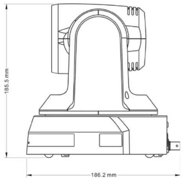
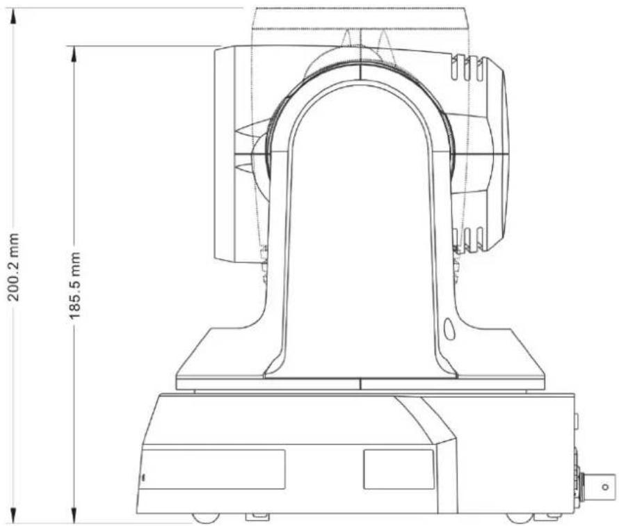
4.2.2.3 Max. rotation dimension of camera
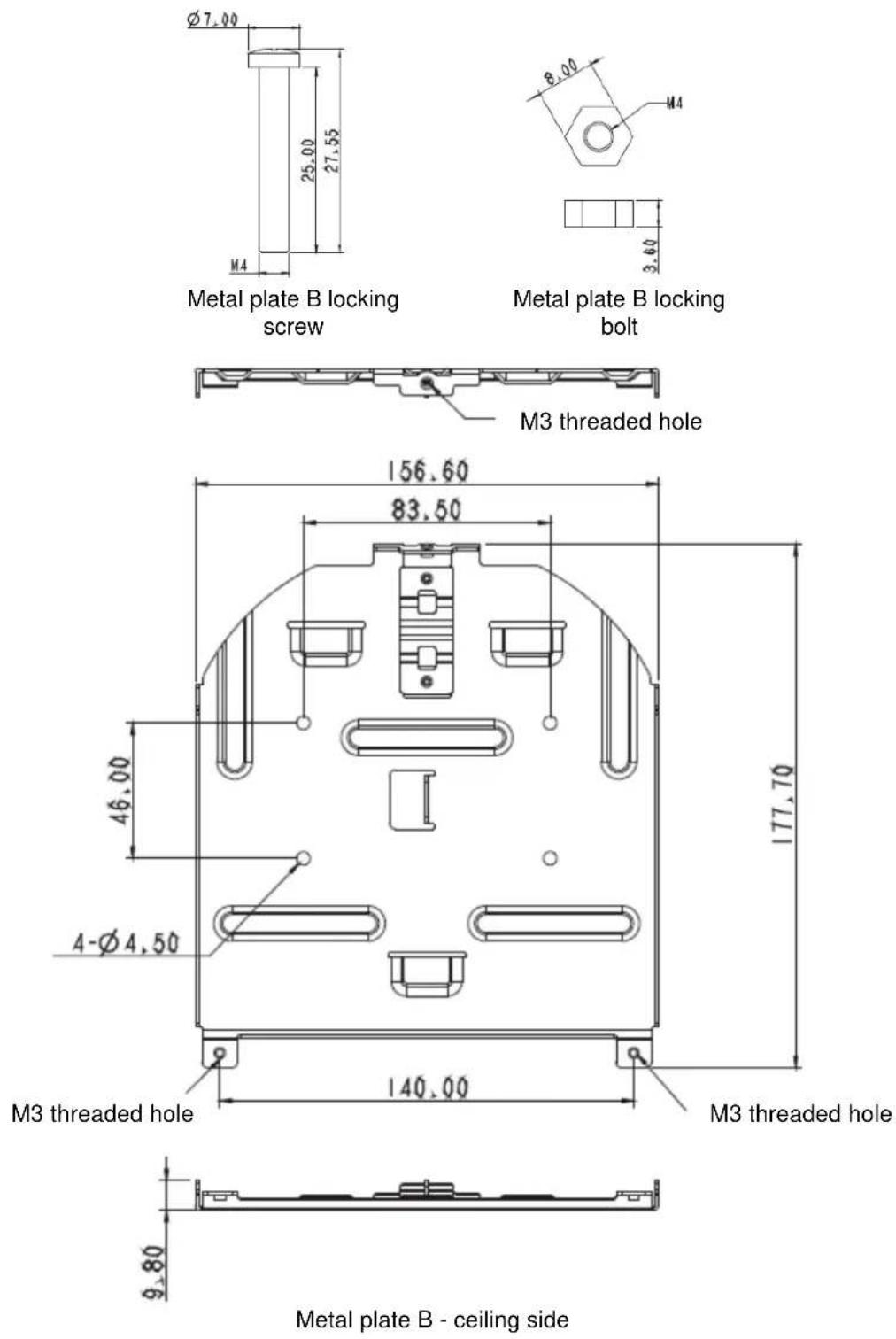
4.2.2.4 Size Diagram
1. Metal plate B - ceiling side
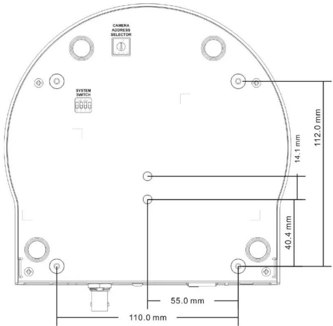
2. Metal plate A - machine side

Metal plate A locking screw
Metal plate A - machine side
3. Bottom of machine
4.2.2.5 Precautions for installation
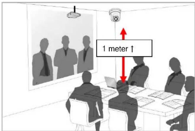
- Before installation, please confirm the orientation of the machine relative to the object to be captured
- It is recommended that the machine should be set at a distance of more than 1 meter away from the object to be captured. Please adjust for a best distance according to the magnification of the lens
-
The machine (including metal plates) is weighed at about 2.5 kg. If it is to be installed on the ceiling, please use the hanger that has obtained UL security approval to prevent the machine from falling.
-
Please check whether the camera is installed securely on a regular basis
4.2.2.6 Installation steps
- Please adjust resolution on DIP switch at first
Note: Please refer to Chapter 8. DIP Switch Setting for the relevant descriptions on DIP switch.
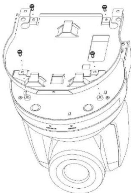
- Fix the metal plate A on the machine base with 4 M3 silver screws
natural_image
Technical line drawing of a mechanical component with mounting holes and internal cavities (no text or symbols)- Lock the metal plate B on ceiling mounted hanger
※Caution:
(1) Please use the hanger that has obtained UL security approval
(2) Please reserve the hole for the connecting wires of the camera
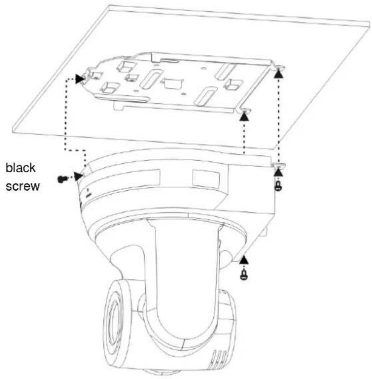
- Combine the metal plate A and the metal plate B
(1) Push the metal plate A up to the ceiling and then to the right to latch the metal plate B
(2) And then secure with 2 M3 silver screws and 1 M3 black screw
4.2.2.7 How to remove
- Remove the connecting wires from the camera
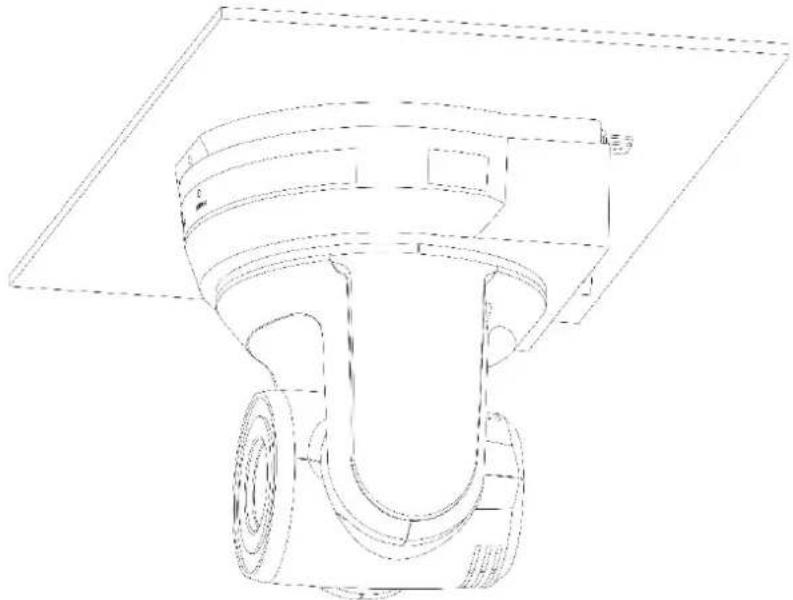
- Uninstall the camera together with the ceiling, loosen the three screws that fix the metal plates A and B and push to the left to remove the machine
natural_image
Technical line drawing of a mechanical component with no visible text or symbols- Then remove the screws on the hanger and the machine
4.3 Connecting devices
4.3.1 Image Output
4.3.1.1 Connecting to PC (video conference)
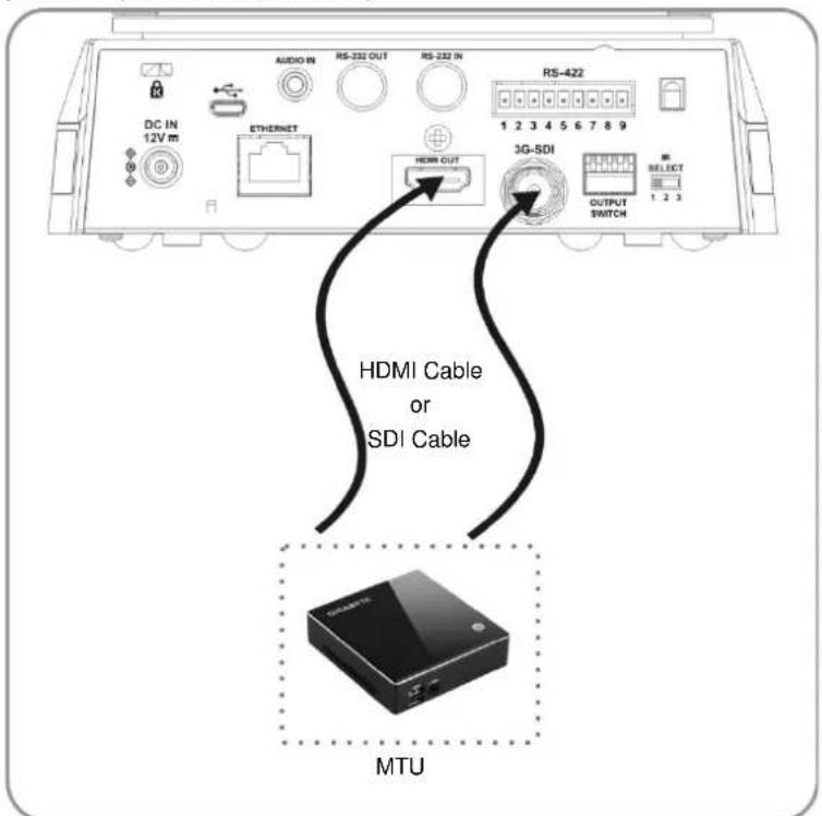
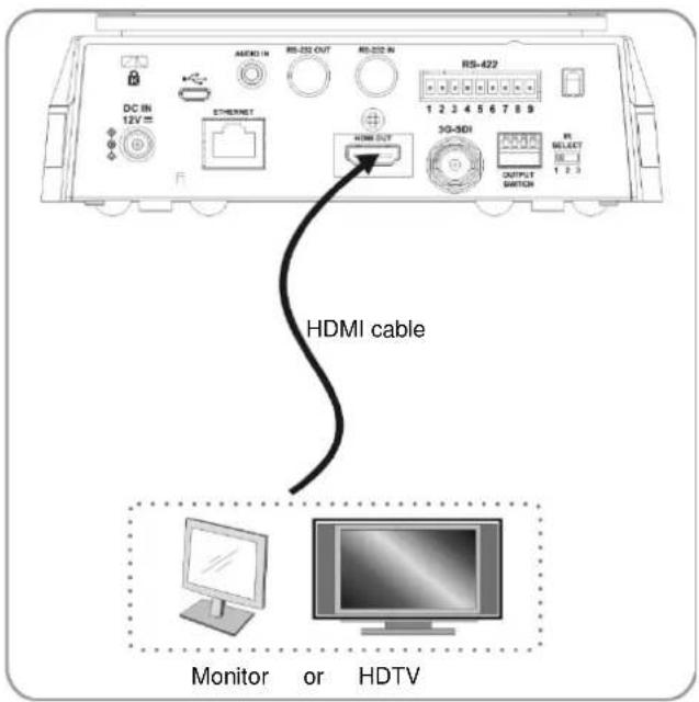
4.3.1.2 Connecting to an HDTV/computer monitor (HDMI)
4.3.1.3 Connecting to Internet
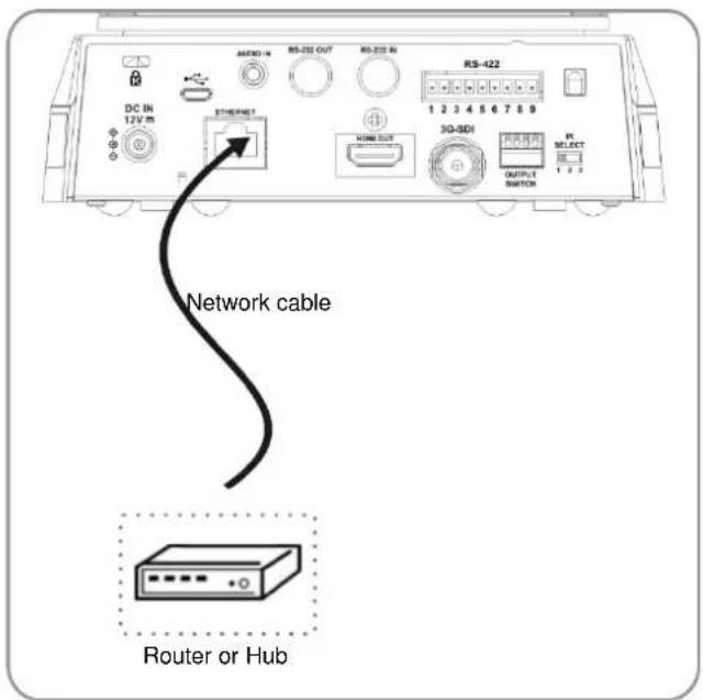
Note: CV620-IPW can be used with browsers, VLC and QuickTime after it is connected to the Internet.
4.3.1.4 Connecting AUDIO IN
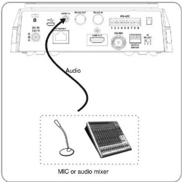
Note: Set the [Audio In] in the OSD to reflect the input device
4.3.2 Controlling VCs with the computer
4.3.2.1 Connecting to one computer for connection between VCs (RS-232 in/out)
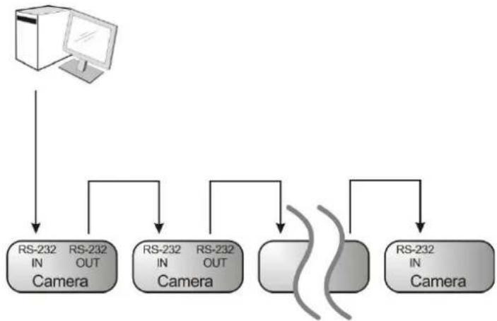
flowchart
graph TD
    A["Computer"] --> B["RS-232 IN Camera"]
    A --> C["RS-232 OUT Camera"]
    A --> D["RS-232 IN Camera"]
    A --> E["RS-232 OUT Camera"]
    B --> F["Output"]
    C --> F
    D --> F
    E --> F
Note: With RS-232 in/out, at most 7 VCs can be connected.
4.3.2.2 Connecting to one computer for connection between VCs (RS-422)
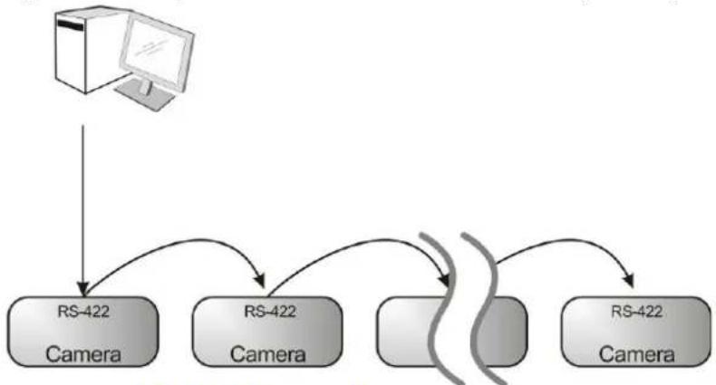
flowchart
graph TD
    A["Computer"] --> B["RS-422 Camera"]
    B --> C["RS-422 Camera"]
    C --> D["Channel 1"]
    C --> E["Channel 2"]
    D --> F["RS-422 Camera"]
    E --> F
Note: Please refer to 8.2 RS-422 connection for the RS-422 connection instructions.
Note: With RS-422, at most 7 VCs can be connected.
4.3.3 Use of CV620-IPW with Internet Connection
4.3.3.1 Setup before use
- Connecting the screen through HDMI output.
- Press [MENU] on the Remote Control to display the OSD menu.
- Shift down to [Ethernet] to modify and confirm the IP address DHCP: Enable/disable the dynamic host configuration protocol
IP Address: Confirm or modify the IP address of CV620-IPW
Subnet mask: 255.255.255.0
Gateway: Preset 192.168.100.254
[Remark] Please modify the above settings based on the LAN setting of the operating environment. To use DHCP, please connect the CV620-IPW to LAN and then confirm IP address.
- After completing settings, press [MENU] to exit the OSD menu.
● After completing setting and confirming IP address, HDMI cable can be disconnected.
4.3.3.2 Start Using
- Connect network cable to CV620-IPW network port to connect CV620-IPW to LAN.
- Press [MENU] on the Remote Control to display the OSD menu.
- Open the browser, and enter the URL of CV620-IPW in the address bar, e.g.: http://192.168.100.150 (default IP address)
- Enter administrator's account and password
Account: admin (Default)
Password: 9999 (Default)
Subnet mask: 255.255.255.0
Gateway: Preset 192.168.100.254
[Remark 1] For details, please refer to Chapter 7 Network Function Settings Description.
[Remark 2] In addition to browsers, other software such as VLC and QuickTime can be used for operation.
Chapter 5. Remote Control and Setting Menu
5.1 Functions of remote control
Note: The below functions are listed alphabetically.
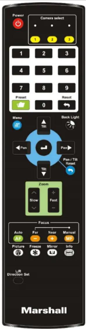
| Item Description | |
| <,>,▲,▼ | Move the lens |
| Back Light Turn on/off back light compensation | |
| Camera select | Choose 1 ~ 3 of CV620-IPW |
| Focus-Manual / Far/Near | Turn on manual focus to adjust the focal length |
| Focus-Auto | Auto focus |
| Freeze Freeze the screen | |
| Home-Enter | Go back to the main page / Execute |
| Info Status information | |
| L/R Direction Set | L/R Direction / Normal |
| Menu Display OSD menu | |
| Mirror Rotate the image (OFF / Mirror / Flip / Rotate) | |
| Pan/Tilt Reset | Clear the Pan / Tilt setting |
| Picture Switch image effect (OFF / NEG / Black & White) | |
| Power Power Switch | |
| Preset | Appoint an ID (0 ~ 9) to save the current position data |
| Reset Appoint an ID (0 ~ 9) to delete the current position data | |
| Zoom-Fast | Adjust image size |
| Zoom-Slow | Fine-tune image size |
5.2 Setting Menu
Note: Press [Menu] on the remote control to enter the setting menu; the bold underlined values in the following table are defaults.
| 1st LevelMajor Items | 2nd LevelMinor Items | 3rd LevelAdjustmentValues | Function Descriptions | |
| Exposure | Mode | 1.Full Auto2.Shutter Pri3.Iris Pri4.Manual5.White Board6.Smooth Auto | Exposure mode setting | |
| Exposure Comp. | On /Off | AE Level | ||
| Exposure Comp.Level | -6~0~5 | The value can be adjusted only after Exposure Comp. is activated | ||
| Shutter Pri | 60/30mode | 50/25mode | Shutter priority setting | |
| 1/10000 | 1/10000 | |||
| 1/5000 | 1/5000 | |||
| 1/3000 | 1/3000 | |||
| 1/2500 | 1/2500 | |||
| 1/2000 | 1/1750 | |||
| 1/1500 | 1/1250 | |||
| 1/1000 | 1/1000 | |||
| 1/725 | 1/600 | |||
| 1/500 | 1/425 | |||
| 1/350 | 1/300 | |||
| 1/250 | 1/215 | |||
| 1/180 | 1/150 | |||
| 1/120 | 1/120 | |||
| 1/100 | 1/100 | |||
| 1/90 | 1/75 | |||
| 1/60 | 1/50 | |||
| 1/30 | 1/25 | |||
| 1/15 | 1/12 | |||
| 1/8 | 1/6 | |||
| 1/4 | 1/3 | |||
| 1/2 | 1/2 | |||
| 1/1 | 1/1 | |||
| Iris Pri | 1. F1.62. F23. F2.24. F2.75. F3.26. F3.87. F4.58. F5.49. F6.310. F7.811. F912. F1113. F1314. F1615. F18 | Iris setting | ||
| Manual Gain | 1. 0dB2. 2 dB3. 4 dB4. 6 dB5. 8 dB6. 10 dB7. 12 dB8. 14 dB9. 16 dB10. 18 dB11. 20 dB12. 22dB13. 24dB14. 26 dB15. 28 dB16. 30 dB | Manually set the gain | ||
| Manual Speed | 60/30 mode | 50/25 mode | Manually set the shutter | |
| 1/10000 | 1/10000 | |||
| 1/5000 | 1/5000 | |||
| 1/3000 | 1/3000 | |||
| 1/2500 | 1/2500 | |||
| 1/2000 | 1/1750 | |||
| 1/1500 | 1/1250 | |||
| 1/1000 | 1/1000 | |||
| 1/725 | 1/600 | |||
| 1/500 | 1/425 | |||
| 1/350 | 1/300 | |||
| 1/250 | 1/215 | |||
| 1/180 | 1/150 | |||
| 1/120 | 1/120 | |||
| 1/100 | 1/100 | |||
| 1/90 | 1/75 | |||
| 1/60 | 1/50 | |||
| 1/30 | 1/25 | |||
| 1/15 | 1/12 | |||
| 1/8 | 1/6 | |||
| 1/4 | 1/3 | |||
| 1/2 | 1/2 | |||
| 1/1 | 1/1 | |||
| Manual Iris | 1. F1.62. F23. F2.24. F2.75. F3.26. F3.87. F4.58. F5.49. F6.310. F7.811. F912. F1113. F1314. F1615. F18 | Manually set the iris | ||
| Gain Limit | 1. 8 dB2. 10 dB3. 12 dB4. 14 dB5. 16 dB6. 18 dB7. 20 dB8. 22dB9. 24dB10. 26 dB11. 28 dB12. 30dB | Max. limit value of electron gain | ||
| Iris Limit | 1. F1.62. F23. F3.24. F4.55. F6.36. F97. F138. F18 | Max. limit value of iris | ||
| WDR | 1. Disable2. 13. 24. 35. 46. 5 | WDR settings | ||
| White Balance | Mode | 1. Auto2. Indoor3. Outdoor4. One Push WB5. ATW6. Manual7. Sodium Lamp8. 3000K9. 4300K10. 5000K11. 6500K12. 8000K13. WideAuto | Select the color temperature mode1. 4000k ~ 7000k2. 3200k3. 5800k4. 1700k ~ 10000k5. 1700k ~ 10000k6. Custom7. 2800k8. 3000K9. 4300K10. 5000K11. 6500K12. 8000K13. 3000k ~ 7000k | |
| One Push Trigger | ENTER | One push trigger | ||
| Manual Red | 0~ C~128 | Adjustable when the white balance mode is set to Manual | ||
| Manual Blue | 0~ C~128 | Adjustable when the white balance mode is set to Manual | ||
| Picture | Picture effect | 1. Disable2. Neg3. B & W | Set the picture effect | |
| Sharpness | 0~ C~15 | Adjust the sharpness of the image | ||
| 2D NR | 1. Auto2. Disable3. 14. 25. 36. 47. 5 | 2D noise reduction settings | ||
| 3D NR | 1. Disable2. Low3. Typ4. Max5. Auto | 3D dynamic noise reduction settings | ||
| Image Mode | 1. Mode 12. Mode 23. Mode 34. Mode 45. Mode 56. Mode 67. Custom | The user may customize his/her desired image mode. | ||
| Image Mode Load | 1. Mode 12. Mode 23. Mode 34. Mode 45. Mode 56. Mode 67. Mode 6 | Adjustable when theimage modeis set toCustom. After selected, the correspondingimage modeparameters will be read and applied toCustom | ||
| Brightness | 0~ C~25 | Adjustable when theimage modeis set toCustom | ||
| Contrast | 0~ C~25 | Contrast adjustment; Adjustable when theimage modeis set toCustom | ||
| Saturation | 0~C~25 | Adjustable in theCustom Mode | ||
| Black Level | 1. Disable2. Type 13. Type 24. Type 35. Type 46. Type 5 | Adjustable in theCustom Mode | ||
| Gamma | 0~C~3 | Adjustable in theCustom Mode | ||
| Skin Tone | 0~C~5 | Skin tone setting, adjustable in theCustom Mode | ||
| Pan Tilt Zoom | Pan/Tilt Limit | ON/Off | Turn on/off the angle limit setting | |
| Pan Right Limit | 0~170 | Limit the right angle | ||
| Pan Left Limit | -170~0 | Limit the left angle | ||
| Tilt UP Limit 0~90 | — | Limit the upward angle | ||
| Tilt Down Limit | -30~0 | Limit the downward angle | ||
| Pan/Tilt Speed | Preset/Low | Adjust Pan/Tilt Speed | ||
| Pan Flip | On/Off | Activate the reverse Pan command | ||
| Tilt Flip | On/Off | Activate the reverse Tilt command | ||
| Preset Speed | 1. 5 per second2. 25 per second3. 50 per second4. 100 per second | Set the rotation speed of the cradle head when Preset is executed | ||
| PTZ Speed Comp | On/Off | PTZ Speed Compensation | ||
| Dig-Effect | Mirror | 1. Disable2. Mirror3. Flip4. Mirror + Flip | Set the mode at which the image is turned | |
| Auto Focus | AF Sensitivity | 1. Low2. Middle3. High | Select the AF triggering speed. The higher the speed is, the faster AF is triggered | |
| AF speed | Fast / Normal | Focus speed after AF triggering | ||
| AF Frame | Full Area/Center Area | AF frame setting, when central area was set as AF frame, focusing will be on the center of the screen. When Full Frame was set as AF frame, focusing will be calculated based on the full screen | ||
| Ethernet | DHCP | On/Off | Enable/Disable DHCP setting using left and right arrow keys and press [ENTER] to apply setting. | |
| IP Address | 192.168.100.150 | Press [ENTER] to modify the items; select the item to be modified using left and right arrow keys, and modify the value using numeric keys. | ||
| Subnet mask | 255.255.255.0 | Press [ENTER] to modify the items; select the item to be modified using left and right arrow keys, and modify the value using numeric keys. | ||
| Gateway | 192.168.100.254 | Press [ENTER] to modify the items; select the item to be modified using left and right arrow keys, and modify the value using numeric keys. | ||
| System | Prompt | On / Off | Turn on/off the prompt information on the display | |
| IR Receive | On / Off | Turn on/off the infrared reception | ||
| Motionless Preset | On / Off | When the function is enabled, the screen will Freeze when Preset is executed. Freeze will be released after Preset is completed. | ||
| Audio In | Line In/Mic In | Set Audio In | ||
| Audio Enable | On / Off | Turn on/off sound output | ||
| Audio Volume | 0~10 | Volume Setting | ||
| Encode Sample Rate | 1. 48 KHz(AAC)2. 44.1 KHz(AAC)3. 16 KHz(G.7114. 8 KHz(G.711) | Set the encode type and sample rate SDI supports the audio output of 48 KHz only. | ||
| Language | English / Chinese | Language | ||
| Output Mode | 1. 1080p/602. 1080p/59.943. 1080p/504. 1080p/305. 1080p/29.976. 1080p/257. 1080i/608. 1080i/59.949. 1080i/5010. 720p/6011. 720p/59.9412. 720p/50 | Set output resolution | ||
| Protocol | Protocol V / Protocol PD | Protocol V: VISCAProtocol PD: PELCO D | ||
| PD Address 1~ C~255 | The Protocol set to PD allows the camera ID address to be assigned | |||
| Factory Reset | On / Off | Resume the factory default setting | ||
| FW Upgrade | On / Off | Upgrade Firmware | ||
| Status | Display the current setting status | |||
Chapter 6. Descriptions of Major Functions
6.1 I would like to switch to CV620-IPW
- Press [Camera 1 \~ 3] on the remote control to select CV620-IPW.
● Camera 1 \~ 3 is selected with IR SELECT.
6.2 I would like to save the current lens position data
- Hold [Preset + ID] on the remote control to save the current position data.
- ID shall be a digit [0 \~ 9].
- Use VISCA Command to store position data to [0 \~ 127]
6.3 I would like to clear the saved position data
- Hold [Reset + ID] on the remote control to clear the given position data.
- ID shall be a digit [0 \~ 9].
- Use VISCA command to clear position data stored in [0 \~ 127]
6.4 I would like to turn on the back light compensation function
- Press [Back Light] on the remote control to turn on or turn off the back light compensation
6.5 I would like to adjust the shooting angle of the lens
- Press [Tilt ▲] or [Tilt ▼] on the remote control to adjust the angle upward or downward.
- Press [Pan ▶] or [Pan ◀] on the remote control to adjust the angle to right or left.
- Press [Pan - Tilt Reset] on the remote control to reset the angle to the center point.
6.6 I would like to zoom in/out images
6.6.1 Adjust image size
- Press [Fast +] on the remote control to zoom in images.
- Press [Fast -] on the remote control to zoom out images.
6.6.2 Fine-tune image size
- Press [Slow +] on the remote control to zoom in images.
- Press [Slow -] on the remote control to zoom out images.
6.7 I would like to adjust the focal length
6.7.1 Auto tune
- Press [AF] on the remote control to adjust automatically.
6.7.2 Manual focus
- Press [MF] on the remote control to turn on the manual focus function.
- Press Focus - [+] or Focus - [-] to adjust.
6.8 I would like to adjust the AF speed
6.8.1 Adjust the AF Sensitivity
Triggering speed of focus. The higher the speed is, the faster focus is triggered
To shoot fast-moving objects, AF Sensitivity can be set to [High] or [Medium], which is applicable to quick focus.
When the environment is too dark to enable auto focus or fixed objects have to be shot in different brightness, AF Sensitivity can be set to [Low].
- Press [MENU] to activate the setting menu.
- Press [▶] or [◀] to select [Auto Focus].
- Press [ENTER] to activate.
- Press [▲] or [▼] to select [AF Sensitivity].
- Press [ENTER] to activate.
- Press [▶] or [◀] to select [High / Middle / Low].
- Press [MENU] to exit.
6.8.2 Adjust the AF speed
The focus speed upon triggering AF Sensitivity
● [Normal] (default): Image flickering may not occur
● [Fast]: Fast focus speed
-
Press [MENU] to activate the setting menu.
-
Press [▶] or [◀] to select [Auto Focus].
-
Press [ENTER] to activate.
-
Press [▲] or [▼] to select [AF speed].
-
Press [ENTER] to activate.
-
Press [▶] or [◀] to select [Fast / Normal].
-
Press [MENU] to exit.
6.9 I would like to set the image mode
- Press [Picture] on the remote control to switch [Off / Neg / B&W].
6.10 I would like to freeze images
- Press [Freeze] on the remote control to freeze the current image on the display.
6.11 I would like to rotate the image
- Press [Mirror] on the remote control to switch [Off / Mirror / Flip / Mirror + Flip].
6.12 I would like to change the camera direction
- Press [L/R Direction Set] on the remote control to switch [L/R Direction / Normal].
6.13 I would like to display the current status
- Press [Info] on the remote control to display the current status information.
6.14 I would like to reset to the default value
Reset to default value using OSD menu
- Press [MENU] → [System] → [Factory Reset] → [On] → [Enter] on the Remote Control and reset to the default value
Chapter 7. Network Function Settings Description
7.1 Web System Requirements
Web Browser: Internet Explorer 8 \~ 11
7.2 Online IP Camera
7.2.1 Connecting to Internet
Two common connection methods are shown below
- Connecting via switch or router
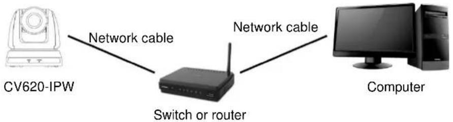
flowchart
graph LR
    A["CV620-IPW"] -->|Network cable| B["Switch or router"]
    B -->|Network cable| C["Computer"]
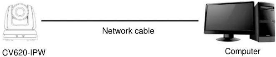
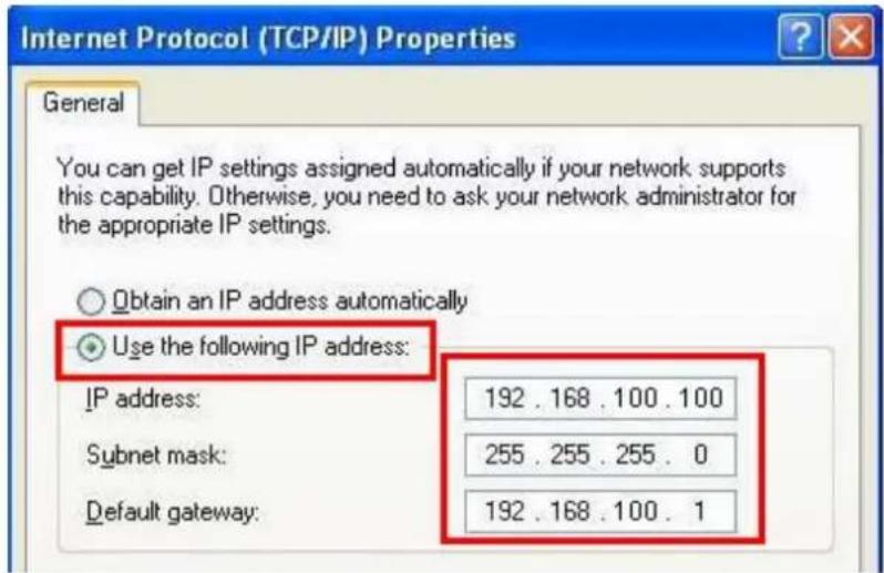
- To connect directly through network cable, the IP address of the computer should be changed so that it is on the same network segment as the camera; for instance 192.168.100.x (preset for camera)
- Connection diagram
flowchart
graph LR
    A["CV620-IPW"] -->|Network cable| B["Computer"]
- Change network settings
7.2.2 Use the web browser
- Open the IE browser, and enter the URL of CV620-IPW in the address bar, such as: http://192.168.100.150 (default IP address)
- Enter administrator's account and password to get started
Account: admin (Default)
Password: 9999 (Default)
Note: 1. "Web Plugin" must be installed before the first use. Please install the program after downloading according to instructions on the screen (as shown in the following figure)
- Please login the computer as Administrator to install it
- After completing installation, please refresh the page.
Installation Guide
The "WebPlugin" file will be downloaded automatically in 7 seconds...
Step:
• 1.Before you begin, close your web browser (i.e. Internet Explorer, Firefox, Chrome, etc.) first.
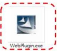
- 2.Double-click "WebPlugin.exe" to start the actual installation process.
• 3. After installation is completed, open the web browser and type in the IP address of the IP Camera

7.2.3 Use RTSP player
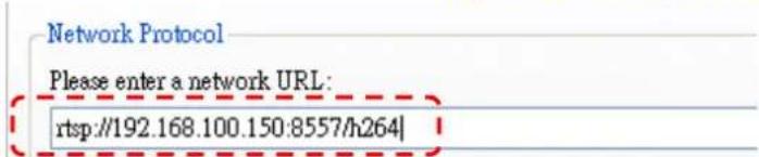
In addition to browser, other RTSP methods can be used for connection, such as VLC and Quick Time RTSP connection address:
- RTSP main stream (h264)=>rtsp://VC IP Address:8557/h264
- RTSP second stream (h264) =>rtsp://VC IP Address:8556/h264
-
RTSP second stream (MJPEG) or single stream in MJPEG=>rtsp://VC IP Address:8555/mjpeg
-
Open the software to enter URL: rtsp://192.168.100.150:8557/h264
7.2.4 Use RTMP connection
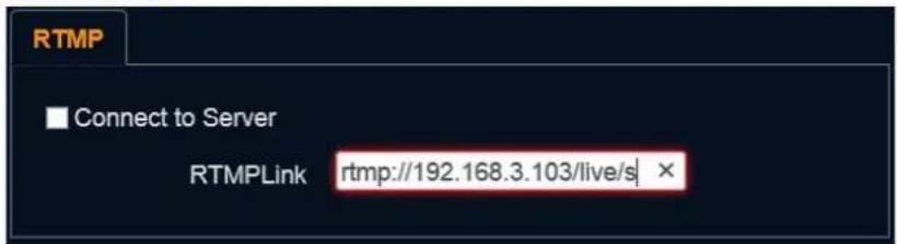
Support RTMP connection. If RTMP server is set up, RTMP connection function can also be opened Please log into CV620-IPW webpage to change RTMP of network setting as described in 7.2.2 Use the Web Browser
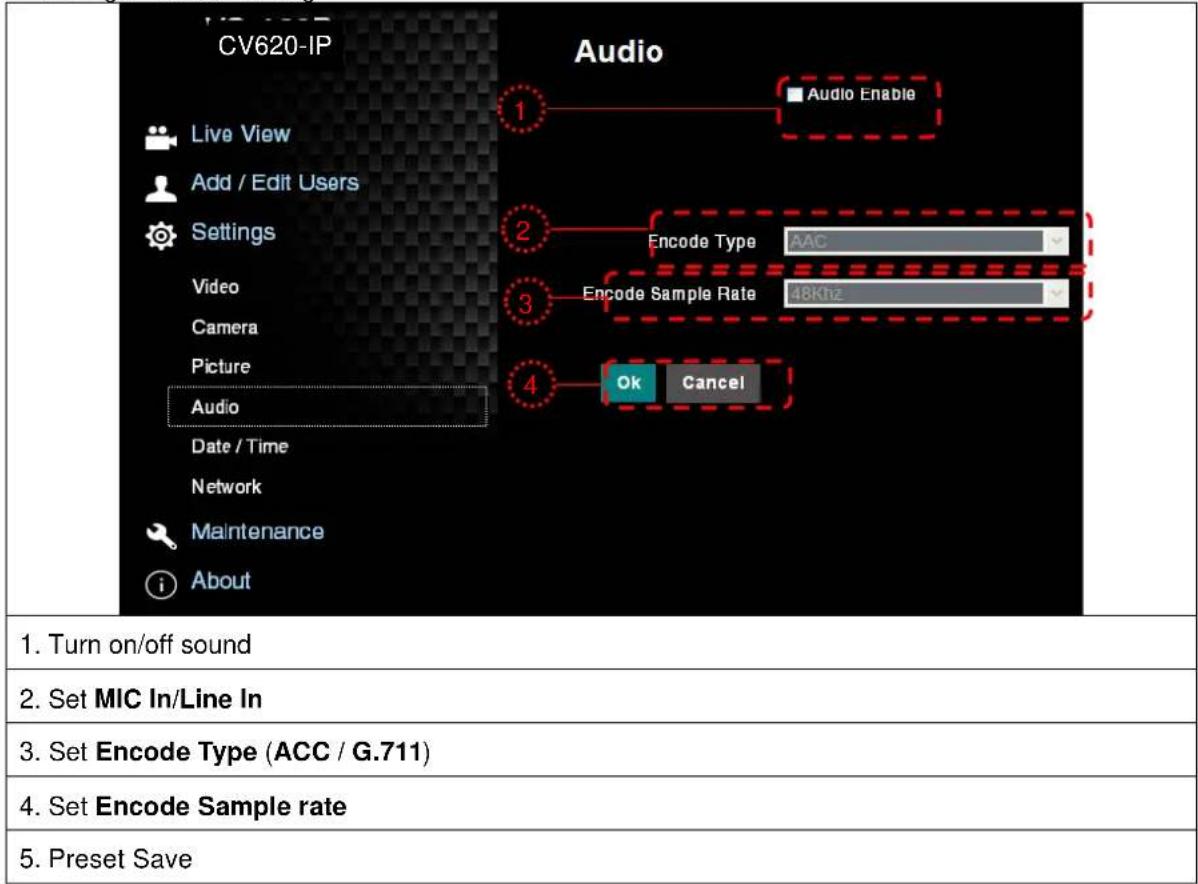
Note: To upload to YouTube for online viewing, please refer to 7.3.9 Settings – Audio Setting and turn on sound
7.3 Web Page Function Description
7.3.1 Login Screen
| Username: Enter user account |
| Password: Enter user password |
| Select Language: Select language from English, Traditional Chinese and Simplified Chinese |
| Remember password: Remember the password so that you do not need to type it next time |
| Login: Log into the administrator screen on the website |
7.3.2 Preview Screen
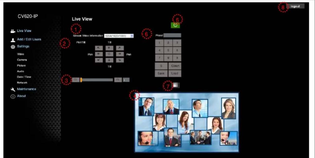
| 1. Information about image encoding form and resolution |
| 2. Rotate camera angle |
| 3. Zoom in/out |
| 4. Preview window |
| 5. Power off CV620-IPW |
| 6. Apply/Set preset |
| 7. Switch to Full Screen |
| 8. Logout |
7.3.3 Account management screen
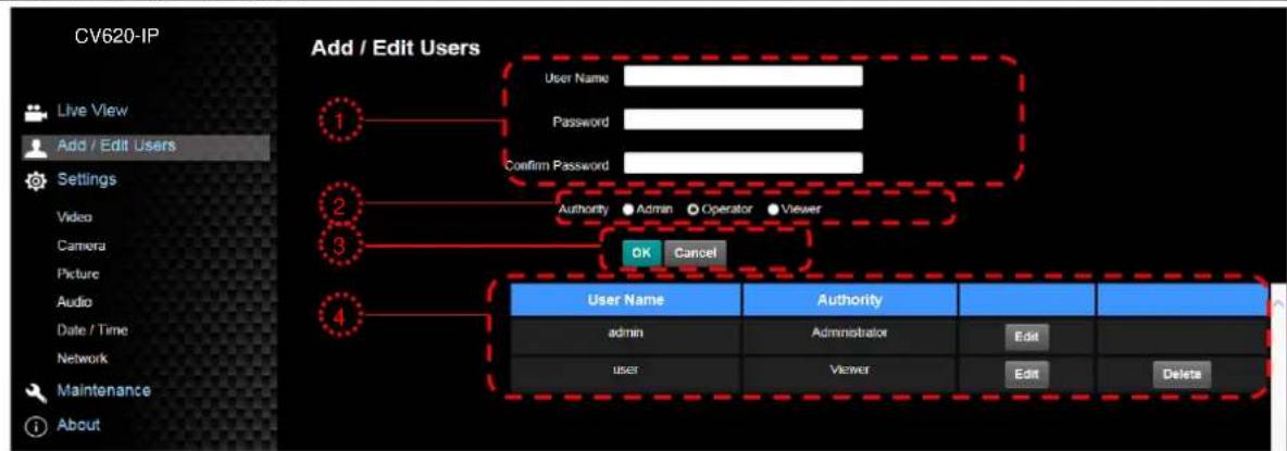
- Enter new username and password
- Set the permissions: Description for permissions is listed in the following table
- Apply
- List of accounts:
Edit: Change password and permission of new account
Delete: Delete new account
Note: Reference for User Permissions
| User Type | Admin | Operator | Viewer |
| View images | Y | Y | Y |
| Settings | Y | Y | N |
| User accounts management | Y | N N |
7.3.4 Settings – Video Setting
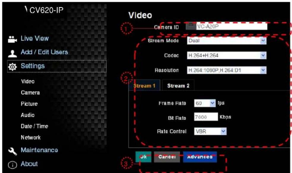
- Camera name: Change camera name on this page
- Select rate and encoding
- Storage setting; for advanced settings, see 7.3.5 Settings – Advanced Video Setting
7.3.5
Settings – Advanced Video Setting
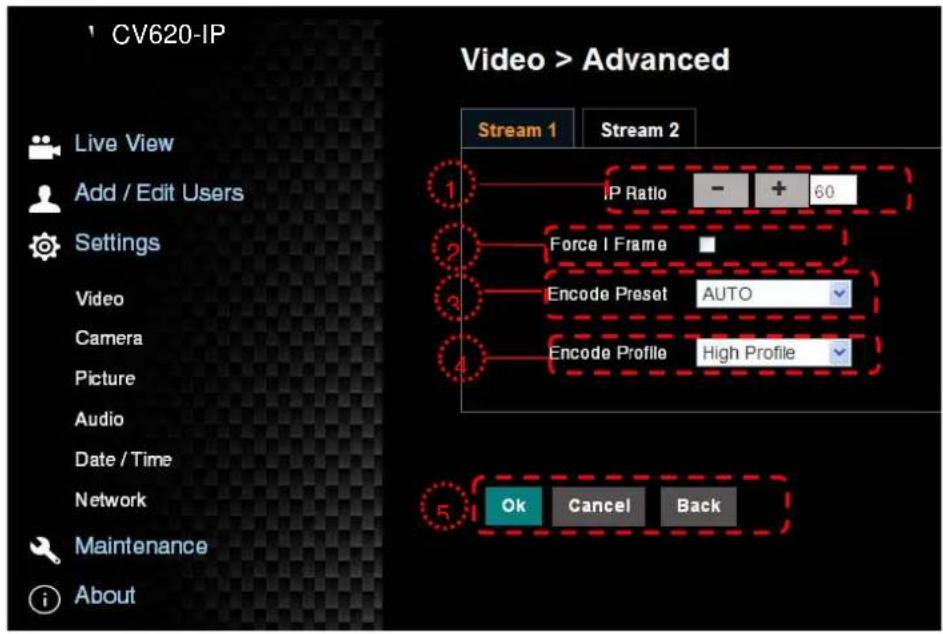
| 1. IP Ratio: Set IP Ratio, from 1 to 60 |
| 2. Force I Frame :Check this item to insert IDR frame into specified series flow and apply its setting. User's setting will be reserved and displayed in GUI interface |
| 3. Encode Preset :Auto: Select between speed and quality depending on the encoding method used (e.g.HIGH_SPEED mode for refresh rate of 60 frames per second and HIGH_QUALITY mode for high image quality)HIGH_SPEED: Refresh rate of 60 frames per second is availableHIGH_QUALITY: Higher image quality can be obtained.SVC: SVC opened encoding mode is applicable to RTSP series flow of 8601, 8602, 8603 and 8604 ports, different refresh rate for different ports. See remark |
| 4. Encode Profile: Encoded Information |
| 5. Preset Save |
Note: SVC connection address: rtsp://VC IP Address:Port/h264
-
60Frame: rtsp://VC IP Address:8557/h264, E.g.: rtsp://192.168.100.150:8557/h264
-
30Frame: rtsp://VC IP Address:8601/h264, E.g.: rtsp://192.168.100.150:8601/h264
-
15Frame: rtsp://VC IP Address:8602/h264, E.g.: rtsp://192.168.100.150:8602/h264
-
7Frame : rtsp://VC IP Address:8603/h264, E.g.: rtsp://192.168.100.150:8603/h264
-
3Frame : rtsp://VC IP Address:8604/h264, E.g.: rtsp://192.168.100.150:8604/h264
7.3.6
Setting - camera
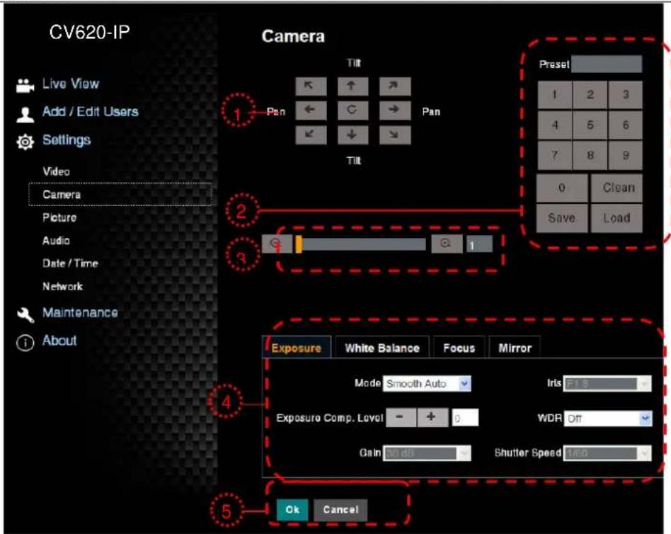
- Rotate camera lens angle
- Save/Read preset
- Adjust image size
- Adjust camera settings. Please refer to 7.3.7 Settings - Advanced Camera Setting
- Preset Save
7.3.7
Settings – Advanced Camera Setting
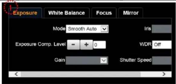
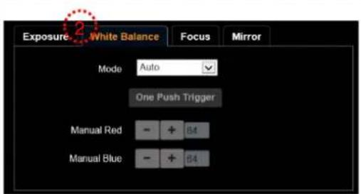
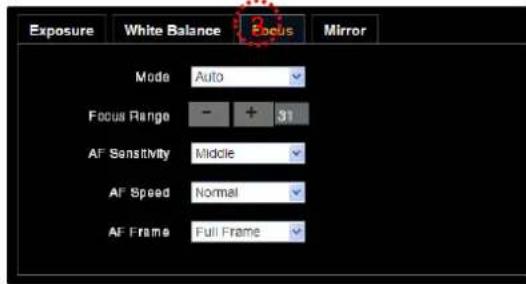
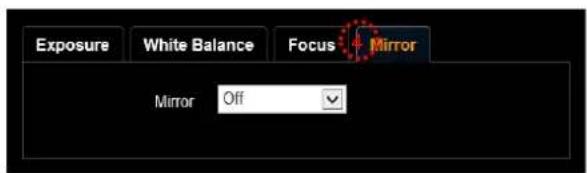
1.. Exposure:
- Mode: Select exposure mode
- Exposure Comp. Level: Select exposure compensation level
• Gain: Adjust gain restriction - Iris: Iris setting
| WDR: WDR settingsShutter Speed: Shutter settings |
| 2. White Balance:Mode: Select the color temperature modeOpen Push Trigger: Single color temperature execution adjustmentManual Red/Blue: Manually adjust blue/red color temperature |
| 3. Focus:Mode: Select manual/automatic focusFocus Range: Set focus rangeAF Sensitivity: Set automatic focus sensitivityAF Speed: Set automatic focus speedAF Frame: Set automatic focus range |
| 4. Mirror:Mirror: Set automatic flip mode |
7.3.8
Settings – Picture Setting
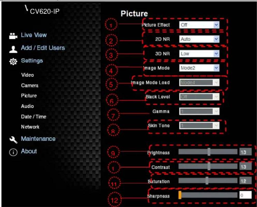
| 1. Picture Effect: Set the picture effect |
| 2. 2D NR: 2D noise reduction settings |
| 3. 3D NR: 3D dynamic noise reduction settings |
| 4. Image Mode: The user may customize his/her desired image mode |
| 5. Image Mode Load: Adjustable when Image Mode is set to Custom, similar to OSD |
| 6. Black Level: Adjustable when Image Mode is set to Custom, similar to OSD |
| 7. Gamma: Adjustable when Image Mode is set to Custom, similar to OSD |
| 8. Skin Tone: Skin tone settings; adjustable when Image Mode is set to Custom, similar to OSD |
| 9. Brightness: Adjustable when Image Mode is set to Custom, similar to OSD |
| 10. Contrast: Adjustable when Image Mode is set to Custom, similar to OSD |
| 11. Saturation: Adjustable when Image Mode is set to Custom, similar to OSD |
| 12. Sharpness: Adjust the sharpness of the image |
7.3.9
Settings – Audio Setting
7.3.10
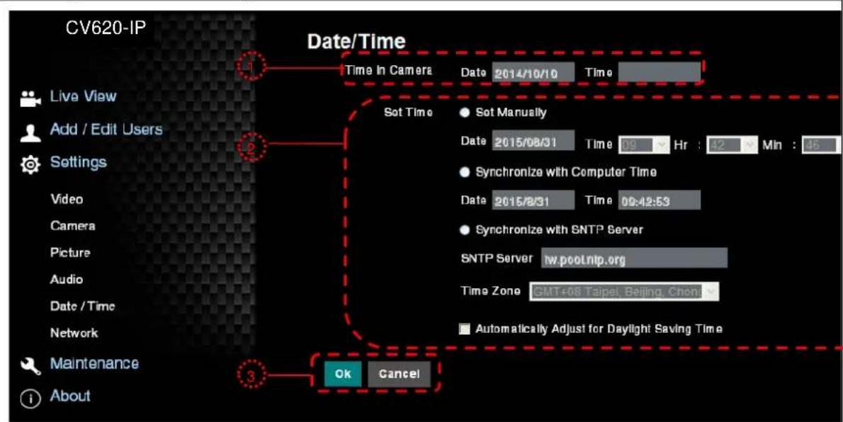
Settings- Date/ Time Setting
-
Current camera date and time
-
Set the Time: Manual setting/synchronous computer time/synchronous SNTP server time/time of automatic adjustment of daylight saving
3. Preset Save
Note: SNTP server address: Please change in network setting
7.3.11
Setting -- Network and Port Setting
| Network Network DHCP IP Address 192.168.3.56 Netm ask 255.255.255.0 Gateway 192.188.3.254 DNS 192.168.1.211 MAC Address DC:E2:AC:00:50:4B |
| RTMP Connect to Server RTMP Server Status : Connection success RTMP Link http://192.168.4.38dem/llumens |
| OK Cancel |
| 1. Network address of camera: Change of setting is available only when DHCP function of camera is turned off; please turn off DHCP function using CV620-IPW screen menu, and for setting of each item of screen menu, see 5.2 Setting Menu |
| 2. Set RTMP: Set connection address of RTMP depending on RTMP Server setting |
| 3. Set RTSP: Enable/Disable Multicast Note: It is suggested to enable Multicast when the number of users online watching the live image simultaneously is more than 4. |
| 4. Set SNTP: Set SNTP Server IP |
| 5. Set HTTP port. The default Port value is 80 Note: Change of setting is available only when DHCP function of camera is closed |
| 6. Preset Save |
Chapter 8. DIP switch setting
Note: Please turn off the machine before changing DIP switch setting.
8.1 DIP SWITCH
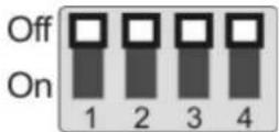
8.1.1 OUTPUT Switch
| Output Mode | Setting | Output Mode | Setting |
| 1920x1080/60p | 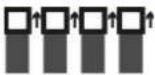 | 1920x1080/50p | 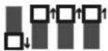 |
| 1920x1080/30p | 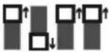 | 1920x1080/25p | 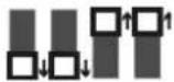 |
| 1920x1080/60i | 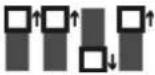 | 1920x1080/50i | 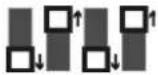 |
| 1280x720/60p | 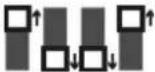 | 1280x720/50p | 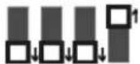 |
| 1080/59.94p | 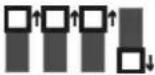 | 1080/59.94i | 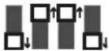 |
| 1080/29.97p | 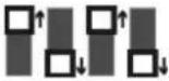 | 720/59.94p | 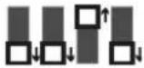 |
8.1.2 IR SELECT
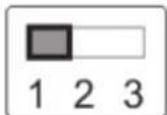
| ID | Setting |
| 1 | |
| 2 | |
| 3 |
8.1.3 Camera Address Selector
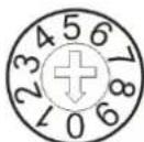
| Setting Function | Descriptions |
| 0~7 | ID 0~7 |
| 8~9 | Reserved |
8.1.4 System Switch
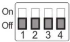
| Setting | Function Descriptions |
| DIP 1 | RS-232C/RS-422 selectorOFF : RS-232C / ON : RS-422 |
| DIP 2 | Infrared signal output switchOFF : Off / ON : On |
| DIP 3 | Communication baud rate selectorOFF : 9600 / ON : 38400 |
| DIP 4 Reserved |
8.2 RS-422 Connection
8.2.1 RS-422 Pin Description
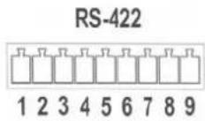
| Pin NO. | Function |
| 1 | RXD OUT - |
| 2 | RXD OUT + |
| 3 | TXD OUT - |
| 4 | TXD OUT + |
| 5 | GND |
| 6 | RXD IN - |
| 7 | RXD IN + |
| 8 | TXD IN - |
| 9 | TXD IN + |
Note:
Please connect IN+ to OUT+ when connecting to SONY products For non-SONY products, it may be necessary to connect IN+ to OUT-
8.2.2 Use RS-422 Connection
- Hold the two sides of RS-422 connector and pull out in the direction shown by the arrow in the figure below
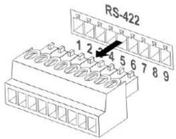
- Peel off a section of copper wire (AWG Nos.28 to 18) and insert it into the connector hole; then use flat screw driver to fix it
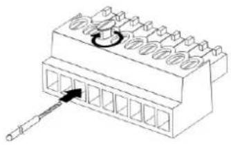
natural_image
Diagram of a connector pinout with a circular arrow indicating rotation (no text or symbols)- Insert the wired RS-422 connector back to the camera. Now the connection is completed
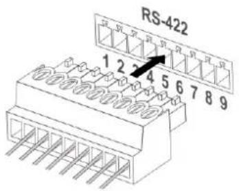
Note: When RS-422 connection is being used, do not use RS-232C connection.
Chapter 9. Troubleshooting
This chapter describes problems you may encounter while using CV620-IPW. If you have questions, please refer to related chapters and follow all the suggested solutions. If the problem still occurred, please contact your distributor or the service center.
| No. | Problems | Solutions |
| 1. | Boot without power signal | Make sure you have plugged in the power cord.Make sure the Service DIP switch is Off. |
| 2. | There is no image output from CV620-IPW | Check the power.Check if DIP switch is properly set. Please refer to Chapter 8 DIP Switch Setting for related settings.Make sure the display supports the output resolution; in general, the resolution is 1080p60/1080i60/720p60.Replace the cables and make sure they are not faulty. |
| 3. | CV620-IPW image is severely delayed | Please use 1080p or 720p 60/50 Hz signals rather than 25/30 Hz signals. |
| 4. | Not working after changes to DIP Switch setting | After completing DIP Switch setting, unplug and reconnect the power cord and turn on the machine to change the setting. |
| 5. | CV620-IPW cannot be operated by remote control | Please confirm if the Camera Select on the remote control can be used together with the IR Select on CV620-IPW.Please prevent CV620-IPW from direct sunshine.Make sure the energy-saving bulb and the IR touch screen are as far as possible to avoid interference.When several CV620-IPW are connected in the same area, the operation of two remote controls at the same time may result in signal interference. It is recommended to use one remote control only. |
| 6. | The device cannot be controlled with Codec | Please consult the distributor to make sure the firmware version is the latest one. The steps to check version is as follows:1.1 Press [MENU] on the remote control1.2 Choose [Status]1.3 Go to Page 5 of [System]1.4 Make sure the firmware version is correct.Make sure the connection is correct (RS-232/422 Input).Make sure System Switch DIP 1 and DIP 3 are correct. |
| 7. | The device cannot be controlled with RS-232/RS422 | Make sure the connection is correct (RS-232/422 Input).Make sure System Switch DIP 1 and DIP 3 are correct. |
| 8. | Whether the Internet can be used for operation | Please refer to Chapter 7 Network Function Description for the Internet usage |
Marshall Electronics, Inc.
20608 Madrona Avenue
Torrance, CA 90503
Phone: (310) 333-0606 / (800) 800-6608
Fax: (310) 333-0688
www.marshall-usa.com

- Table of Contents
- Chapter 1. Safety Instructions....3
- Chapter 2. Package Contents ....5
- Chapter 3. Product Overview....6
- Chapter 4. Instruction for installation....7
- Chapter 5. Remote Control and Setting Menu .... 18
- Chapter 6. Descriptions of Major Functions ...... 25
- Chapter 7. Network Function Settings Description ......27
- Chapter 8. DIP switch setting ...... 36
- Chapter 9. Troubleshooting ...... 39
- Chapter 1. Safety Instructions
- Operation
- Installation
- Storage
- Cleaning
- Remote control (if the accessories are equipped with remote control)
- ■ Precautions
- ■ FCC Warning
- Chapter 2. Package Contents
- Chapter 3. Product Overview
- Overview
- Description of LED indicator
- Chapter 4. Instruction for installation
- Preparation before installation
- Instruction for installation
- I would like to install CV620-IPW on the desk
- Installation steps
- I would like to install CV620-IPW on the ceiling
- Prepare for the parts and equipment required during the installation
- Camera Size
- Max. rotation dimension of camera
- Size Diagram
- Metal plate B - ceiling side
- Metal plate A - machine side
- Bottom of machine
- Precautions for installation
- Installation steps
- How to remove
- Connecting devices
- Image Output
- Connecting AUDIO IN
- Controlling VCs with the computer
- Use of CV620-IPW with Internet Connection
- Setup before use
- Start Using
- Chapter 5. Remote Control and Setting Menu
- Functions of remote control
- Setting Menu
- Chapter 6. Descriptions of Major Functions
- I would like to switch to CV620-IPW
- I would like to save the current lens position data
- I would like to clear the saved position data
- I would like to turn on the back light compensation function
- I would like to adjust the shooting angle of the lens
- I would like to zoom in/out images
- Adjust image size
- Fine-tune image size
- I would like to adjust the focal length
- Auto tune
- Manual focus
- I would like to adjust the AF speed
- Adjust the AF Sensitivity
- Adjust the AF speed
- I would like to set the image mode
- I would like to freeze images
- I would like to rotate the image
- I would like to change the camera direction
- I would like to display the current status
- I would like to reset to the default value
- Chapter 7. Network Function Settings Description
- Web System Requirements
- Online IP Camera
- Connecting to Internet
- Use the web browser
- Installation Guide
- The "WebPlugin" file will be downloaded automatically in 7 seconds...
- Step:
- Use RTSP player
- Use RTMP connection
- Web Page Function Description
- Account management screen
- Settings – Video Setting
- 7.3.5
- 7.3.6
- 7.3.7
- 1.. Exposure:
- 7.3.8
- 7.3.9
- 7.3.10
- Preset Save
- 7.3.11
- Chapter 8. DIP switch setting
- DIP SWITCH
- OUTPUT Switch
- IR SELECT
- Camera Address Selector
- System Switch
- RS-422 Connection
- RS-422 Pin Description
- Note:
- Use RS-422 Connection
- Chapter 9. Troubleshooting
- Marshall Electronics, Inc.
Brand : Marshall Electronics
Model : CV620-IPW
Category : Security Camera