
UNITE 100 - Video Conferencing System ClearOne - Free user manual and instructions
Find the device manual for free UNITE 100 ClearOne in PDF.


| Product Type | PTZ HD Video Conferencing Camera System |
| Brand | ClearOne |
| Model | UNITE 100 |
| Image Sensor | 1/2.8 inch 2 Megapixel HD CMOS |
| Video Resolution | 1080p60/50/30/25, 720p60/50/30/25 |
| Lens | 3.92mm – 47.3mm, F1.8 – F2.8, Angle of View: 72.5° – 6.3° |
| Optical Zoom | 12x |
| Pan Range | ±170° |
| Tilt Range | -30° to +90° |
| Pan Speed | 0.1° – 180°/sec |
| Tilt Speed | 0.1° – 80°/sec |
| Presets | 10 (up to 128 via serial command) |
| Video Output Interfaces | USB 3.0 (B Male), DVI-I (includes HDMI and YPbPr) |
| Control Interface | 8-pin mini DIN RS232, RS485, VISCA/Pelco-D/Pelco-P protocols |
| Power Supply | DC 12V, 2A |
| Max Power Consumption | 12W |
| Weight | 1.3 kg |
| Included Accessories | Power adapter, power cable, USB 3.0 cable (or DVI cable), RS232 cable, remote controller, user manual, 4 double-sided adhesive strips |
| Remote Control | Infrared, controls PTZ, zoom, focus, menu, presets |
| On-Screen Display (OSD) Menu | Yes, via remote for system, camera, PTZ, video format, reset, help |
| Working Temperature | 23°F to 113°F (-5°C to +45°C) |
| Storage Temperature | -4°F to 140°F (-20°C to +60°C) |
| Maintenance | Use soft cloth and mild cleanser; avoid strong or corrosive cleansers |
| Safety Warnings | Avoid moisture, shock, strong magnetic fields; install on level surface; use specified power supply |
| Compliance | FCC Part 15 Class A, Canadian ICES-003 |
| Support | Phone: 1.800.283.5936, Email: tech.support@ClearOne.com, Web: www.ClearOne.com |
Frequently Asked Questions - UNITE 100 ClearOne
User questions about UNITE 100 ClearOne
0 question about this device. Answer the ones you know or ask your own.
Ask a new question about this device
Download the instructions for your Video Conferencing System in PDF format for free! Find your manual UNITE 100 - ClearOne and take your electronic device back in hand. On this page are published all the documents necessary for the use of your device. UNITE 100 by ClearOne.
USER MANUAL UNITE 100 ClearOne
natural_image
Black and white photo of a video camera with a remote control and a scroll wheel (no visible text or symbols)Table of Contents
INTRODUCTION
Preface....1
Warning Notes....1
Features....2
Parts Included 2
INSTALLATION
Connections 3
Setup 3
CAMERA PHYSICAL DESCRIPTION
Camera Specifications....6
Dimensions....7
RS232/DB9 Interface....7
Remote Controller Explanation 8
MENU CONTROL OF THE CAMERA
Main Screen....9
System Option....10
Camera Option....11
PT Option....13
Reset Option....14
Help Option 14
Exit Option....14
COM CONTROL OF THE CAMERA
VISCA Protocol....15
Part 1: Camera Return Command....15
Part 2: Camera Control Command ....16
Part 3: Inquiry Command ....19
Pelco-D: Protocol Command List....20
Pelco-P: Protocol Command List 21
TROUBLESHOOTING THE CAMERA CONTROL OF THE CAMERA
Camera Maintenance....23
Camera Misuse 23
Troubleshooting 23
COMPLIANCE
SERVICE AND SUPPORT
Introduction
PREFACE
Thanks for using the UNITE 100 PTZ (Pan-Tilt-Zoom) HD camera.
This manual introduces the functions, installation, and operation of the HD camera. Please read the manual thoroughly before installation and usage.
WARNING NOTES
Use this product only under the specified conditions to avoid any damage or danger.
Moisture - Do not expose the camera to rain or moisture.
Shock Hazard - Do not perform any unauthorized modification or dismantling. To reduce the risk of electric shock, do not remove the cover. Refer servicing to qualified personnel. ClearOne is not responsible for any unauthorized modification or dismantling.
Environmental - Never operate the camera when the temperature, humidity, or power are out of the authorized ranges. Do not expose the camera to corrosive materials, liquids or gasses.
Cleaning - To avoid scratching, use only a soft cloth and mild cleansers to clean the camera.
Magnetism - Strong electromagnetic fields near the camera may affect the image quality.
Electrical Safety - Installation and operation must comply with electrical safety standards.
Transport - Avoid stress, vibration, and moisture in transport, storage, and installation.
Placement - The camera must be placed on a level desk or platform, and it must not be installed on a slant. No object should restrict the camera range of motion.
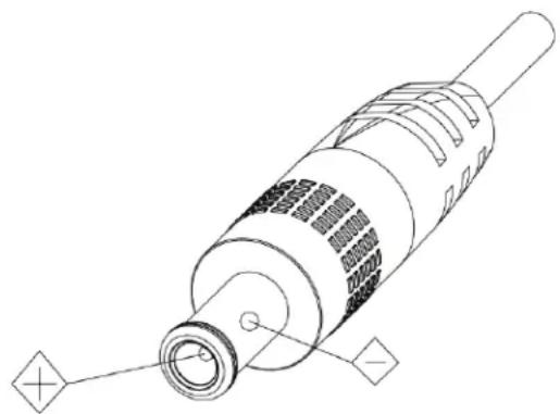
Power Supply Polarity - The power supply is rated ±12 VDC at 2 Amps. The polarity of the power supply as shown in the following drawing:
natural_image
Technical line drawing of a cylindrical electronic component with internal structure and mounting holes (no text or symbols)FEATURES
The UNITE 100 camera has the following features.
- Easy to use menu operation.
- High-speed USB 3.0 interface, DVI-I interface (including HDMI and YPbPr).
- Includes IR remote controller. The camera can receive both its own remote controller signals, and signals from terminal equipment through the VISCA IN to the terminal equipment IR receiver.
PARTS INCLUDED
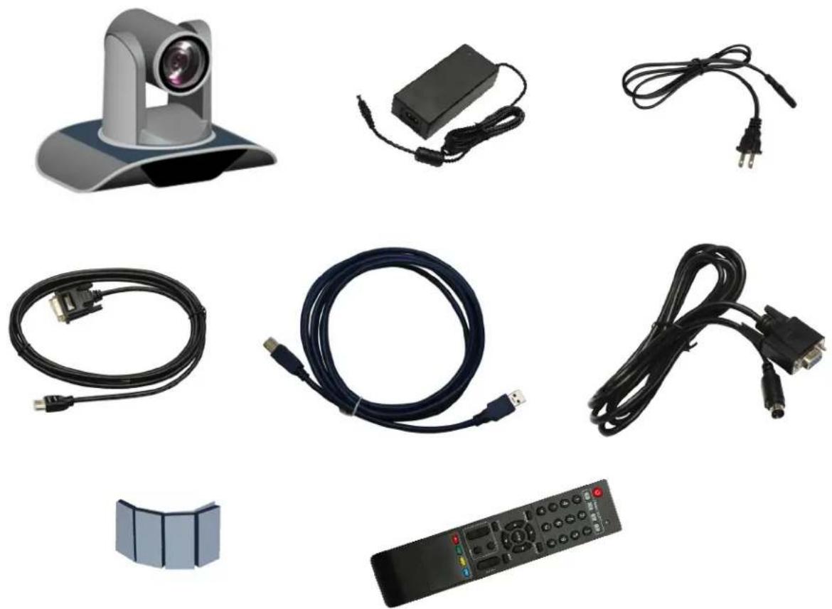
The UNITE HD Camera includes the following:
- Camera.
• Power adapter - Power cable
• USB 3.0 data cable or DVI Cable - RS232 cable
- Remote controller
- User manual
• Four double-side adhesive strips
Please check if your order is complete. Contact ClearOne if there is any question about your shipment.
natural_image
Collection of electronic devices including a video camera, charging cable, USB cable, remote control, and power cord (no text or symbols visible)Installation
When setting up the camera, never move the camera by seizing the camera head. Don't rotate camera head by hand; otherwise, mechanical trouble will occur.
Observe all warnings listed at the beginning of this manual
For stability, the base can be fixed in place by the double-sided adhesive strips.
To prevent damage to the camera, never turn the camera power on before installation is completed.
CONNECTIONS
The connections to the camera are as illustrated below:
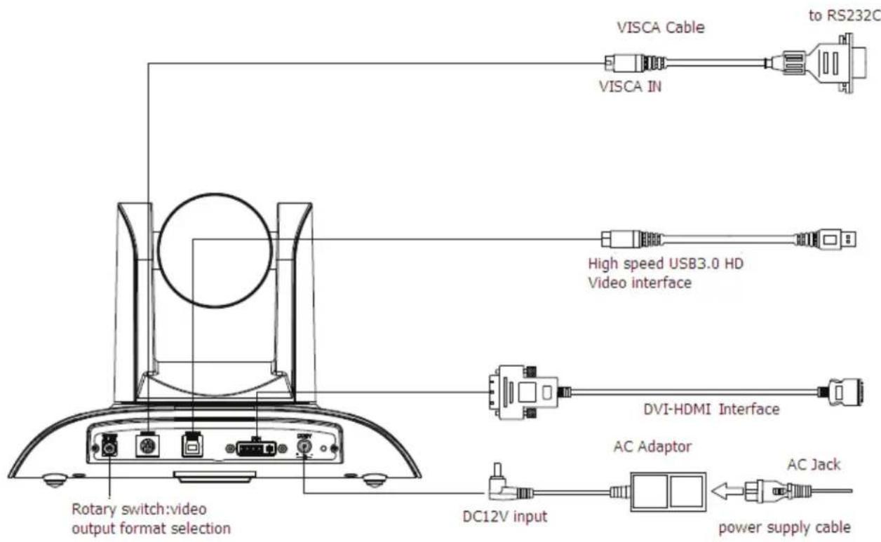
» Note: You will connect the USB or DVI cable depending on which is sent with your equipment.
SETUP
Perform the following:
-
Make the power connection, but don't plug in the supply to turn the camera power on.
-
Set the Working Mode switch setting at the bottom of the camera as shown in the following illustration:

| Switch Position | |
| 1 | ON |
| 2 | ON |
| 3 OFF | |
| 4 | ON |
- Plug in the power supply to turn the supply on, the camera indicator light illuminates red.
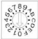
| Dial Position Video Setting | |
| 0 1080P60 | |
| 1 1080P50 | |
| 2 1080P30 | |
| 3 1080P25 | |
| 4 720P60 | |
| 5 720P50 | |
| 6 720P30 | |
| 7 720P25 | |
| 8 ---- | |
| 9 ---- | |
| A ---- | |
| B ---- | |
| C ---- | |
| D ---- | |
| E ---- | |
| F Video format set via OSD menu | |
- Confirm that in the computer the camera is attached to, the computer device manager has universal serial bus (usb) controller are "USB3.0 Root Hub" and "USB3.0 eXtensible Host Controller." If not, please install the Intel(R)_USB_3.0_extensible_Host_Controller_Driver.
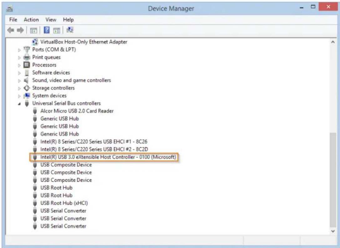
- When the camera is powered-on and begins to initialize, it will first rotate horizontally to the left limit position, then down to the bottom limit; finally it will move both horizontally and vertically to the middle position. The motor then stops running, and initialization is completed.
» Note: If the power-on mode is opened and saved at preset position 0 or 1, then the pan/tilt will be set to the 0 or 1 preset position.
- Test the remote functionality with the camera by resetting the camera to it's factory settings through the On-Screen-Display (OSD) with the menu key of remote controller, [MENU] ->
-> , moving the left/right keys ◀▶ to select , then confirm by [HOME] key as the following:
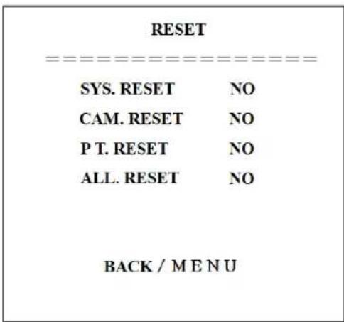
Camera Physical Description
The following illustration shows the various features, controls, and connections:
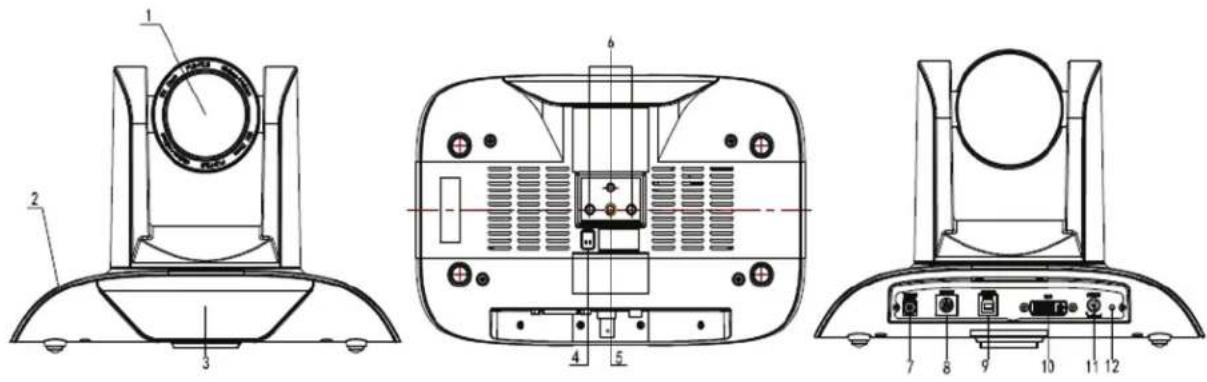
| 1. Camera Lens 7. Video Output Format Selection Switch | |
| 2. Camera Base 8. RS232 Control Interface | |
| 3. Power Indicator Light 9. USB3.0 B Male Interface | |
| 4. Working Mode Selection Switch 10. DVI-I Video Output | |
| 5. Tripod Screw Hole 11. 12VDC Input Power Supply Jack | |
| 6. Mounting Holes (currently not used) 12. Power Indicator Light |
CAMERA SPECIFICATIONS
| Video Format 1080P60/50/30/25 7 | 20P60/50/30/25 |
| Video Output Interfaces USB3.0, DVI-I (including the HDMI and YPbPr signal) | |
| Image Sensor 1/2.8 inch 2 Megapixels high quality HD CMOS Sensor | |
| Lens 3.92mm ~ 47.3 mm, F1.8 - 2.8, angle of view: 72.5°- 6.3° | |
| Rotation ±170° for pan rotation, and -30°~+90° for tilt rotation,support upside down installation | |
| Speed 0.1°-180°/sec for pan rotation, 0.1°-80°/sec for tilt rotation | |
| Presets 10 preset positions (up to 128 presets by serialcommand), precision error less than 0.2° | |
| White Balance, Exposure, Focus Auto/Manual white balance/indoors/out doors/ ControllerAuto/Auto-track white balance , Auto/Manual exposure(iris, shuttle), Auto/Manual/One Push focus | |
| Wide Dynamic Range (WDR) Support WDR function with performance ≥100dB | |
| Control Interface | 8 pins mini DIN, RS232, VISCA/Pelco-D/Pelco-P protocol |
| Power Interface | HEC3800 power jack , Power supply adapter: 12VDC/2A |
| Max Power Consumption | 12W |
| Working Temperature | 23°F to 113°F (-5°C to +45°C) |
| Storage Temperature | -4°F to -140°F (20°C to +60°C) |
| Weight | 1.3 Kg |
DIMENSIONS
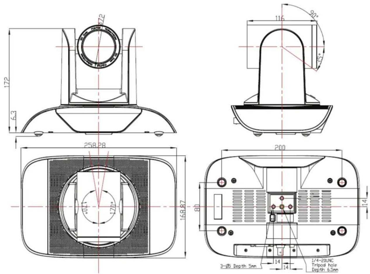
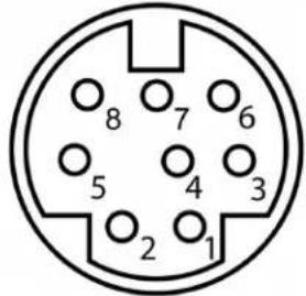
RS232/DB9 INTERFACE
Note the required connections:
| Camera Pinout | RS232 Interface DB9 Interface | |||
| Camera Pin/Function | Mini DIN Pin/Function | Camera Pin/Function | DB9 Pin/Function | |
 | 1. DTR 1. DTR 1. DTR 1. CD | |||
| 2. DSR 2. DSR 2. DSR 2. RXD | ||||
| 3. TXD 3. TXD 3. TXD 3. TXD | ||||
| 4. GND 4. GND 4. GND 4. DTR | ||||
| 5. RXD 5. RXD 5. RXD 5. GND | ||||
| 6. RS485-A 6. GND 6. RS485-A 6. DSR | ||||
| 7. IR OUT - 7. IR OUT 7. RTS | ||||
| 8. RS485-B | - | 8. RS485-B | 8. CTS | |
Camera Operation Using the Remote
This section describes the IR Remote Controller and its use with the Unite Camera.
| Control Description | |
| 0 Standby KeyAfter pressing the Standby Key, the camera will go into standby mode. The front indicator light is off, but blinks every 20 sec. Press the Standby Key again and the camera will perform a self-check and return back to the home position. If the power on mode is set, it will automatically run to the preset position. | |
| 1 Number KeysUsed for setting or moving to presets.If a preset has been established for a number, pressing that number key will move the camera to the assigned preset position. | |
| 2 | * KeyUsed in key combinations |
| 3 Set Preset/Clear Preset Position KeysSet a Preset Position Key:Move camera to desired position,Set Preset + 0-9 number key:Clear a Preset key:Clear Preset key + 0-9 number keyClear all the Preset Position Keys:#++# | |
| 4 - Unavailable - | |
| 5 Focus Control KeysAutomatic focus:AutoManual focus:ManualFocus+: Adjust focus near to farFocus-: Adjust focus far to near | |
| Control Description | |
| 6 Camera SelectionSelect the camera to be controlled. (The camera address number is assigned using the Camera IR Remote Control Address Setting in control item 11 below.) | |
| 7 # KeyUsed in key combinations. | |
| 8 Pan/Tilt Control KeysTilt UP: Press key ▲ upTilt DOWN: Press key ▼ downPan LEFT: Press key ◀ leftPan RIGHT: Press key ▶ rightHOME key: Return to the middle position | |
| 9 MenuOpen or close the On-Screen-Display (OSD) menu. | |
| 10 Zoom KeyZoom OUT: press ZOOM ▲ keyZoom IN: press ZOOM ▼ keyPress and hold the key, the camera will keep zooming in or zooming out and stops as soon as the key is released. | |
| 11 Camera IR Remote Control Address SettingCamera Address No. 1: *+#+F1Camera Address No. 2: *+#+F2Camera Address No. 3: *+#+F3Camera Address No. 4: *+#+F4A single remote can be used to control up to 4 cameras if each one receives it's own Camera Address.Example: Pressing * + # + F2 will assign address 2 to the camera. Afterwards, select Camera Address 2 with the Camera Select keys on the remote (see control 6 above) before the remote can be further used to control the camera. |
Menu Control of the Camera
The UNITE camera settings can be controlled via the remote controller using the On-Screen-Display menus. This section describes the menu options and the settings they control.
In normal working mode, press the [MENU] key to display the menu.
MAIN SCREEN
Use the remote control position keys ▲▼ to navigate to the menu item.
Then click the [HOME] key to open the menu item.
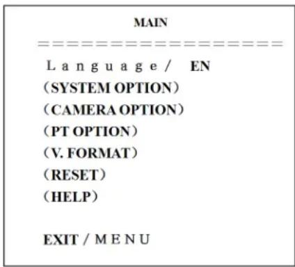
LANGUAGE: Language setting, Chinese / English
SYSTEM OPTION: System setting submenu
CAMERA OPTION: Camera setting submenu
PT OPTION: Pan/Tilt setting submenu
V. FORMAT: Video Format setting submenu
RESET: Reset camera settings
HELP: Help describes menu key operation
EXIT/MENU: The [MENU] key exits the MAIN menu
SYSTEM OPTION
From the MAIN MENU, move the pointer to
| SYSTEM SET | |
| PROTOCOL | VISCA |
| ADDR | 01 |
| B. RATE | 9600 |
| RS485 | off |
| ARM. VER | 1.0A |
| FPGA. VER | 1.0 |
| MODEL | UH-M |
| BACK / MENU | |
PROTOCOL: Reset condition VISCA
Protocol type: VISCA/Pelco-P/Pelco-D
ADDR: Reset condition: 01
VISCA=1\~7 Pelco-P/Pelco-D = 1\~63
B. RATE: Reset condition:9600
2400/4800/9600/115200
RS485: Reset condition: off
ON when using RS485 communication
ARM.VER/FPGA.VER/CAM.VER: Software version information
Model: Camera internal identifier code, UH-M
BACK/MENU: The [MENU] key returns to the MAIN menu
CAMERA OPTION
From the MAIN MENU, move the pointer to
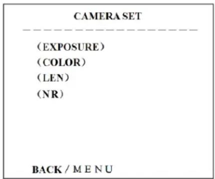
EXPOSURE: Exposure submenu
COLOR: Color settings submenu
LEN: Lens focus submenu
NR: NR submenu
BACK/MENU: The [MENU] key returns to the previous menu
Exposure Submenu
From the CAMERA SET screen, move the pointer to the
| EXPOSURE SETTING | |
| EXP. MODE | Auto |
| SHUTTER | -- |
| IRIS | -- |
| GAIN | -- |
| BRIGHT | 3 |
| EV. MODE | off |
| LEVEL | -- |
| WDR | off |
| LEVEL | -- |
| BACK / MENU | |
EXP. MODE: Reset condition
Auto/Manual. Manual setting allows Shutter, Iris and Gain to be manually set
SHUTTER: Reset condition Default.
Available selections: 1/60 1/90 1/100 1/125 1/180
1/250 1/350 1/500 1/725 1/1000 1/1500 1/2000
1/3000 1/4000 1/6000 1/10000
IRIS: Reset condition Default
Aperture control of camera. 0-13
GAIN: Electronic amplification of the video signal. 0-15
BRIGHT: Brightness control. Reset condition 3, 0-9
EV MODE: Reset Condition: off, Available: On/Off (only available in Auto mode)
WDR: Wide Dynamic Range
BACK/MENU: The [MENU] key returns to the previous menu
Color Submenu
From the CAMERA SET screen, move the pointer to the
| COLOR | |
| WB.MODE | ATW |
| R.GAIN | -- |
| B.GAIN | -- |
| GAMMA | 3 |
| SATURATION | 3 |
| APERTURE | 3 |
| FLICK | 50HZ |
| NR LEVEL | 5 |
| CONTRAST | 3 |
| BACK / MENU | |
WB MODE: Reset Condition: ATW
White balance mode setting: Auto, Indoor, Outdoor, OnePush, ATW, Manual
R.GAIN: Reset condition Default.
Red gain setting: 0-50 (only available in Manual mode)
B.GAIN: Reset condition Default
Blue gain setting: 0-50 (only available in Manual mode)
GAMMA: Reset Condition:0
GAMMA setting: 0-3
SATURATION: Reset condition 3, Saturation setting: 0-9
APERTURE: Reset Condition: 5, Aperture setting: 0-9
FLICK: Reset Condition: Off, FLICK setting: 50HZ/60HZ/OFF
NR LEVEL: Reset Condition: 2, NR LEVEL setting: 0-9
CONTRAST: Reset Condition: 3, CONTRAST setting:0-9
BACK/MENU: The [MENU] key returns to the previous menu
LEN Submenu
From the CAMERA SET screen, move the pointer to the
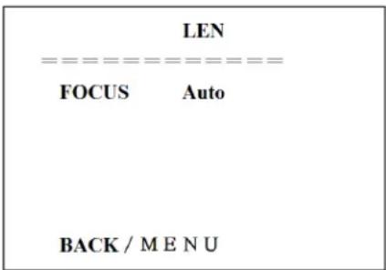
FOCUS: Auto, Manual, OnePush
BACK/MENU: The [MENU] key returns to the previous menu
NR Submenu
From the CAMERA SET screen, move the pointer to the
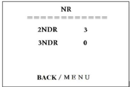
2NDR: 2D Noise reduction; 0-9
3NDR: 3D Noise reduction; 0-3
BACK/MENU: The [MENU] key returns to the previous menu
PT OPTION (PAN/TILT)
From the MAIN MENU, move the pointer to the
| PT SET | |
| POWER. ACT | Off |
| SPEEDBYZ | On |
| MOUNT. MODE | Up |
| IR M. SPEED | 16 |
| IR Z. SPEED | 07 |
| MIN. SPEED | 0 |
| SCAN. SPEED | 10 |
| BACK / MENU | |
POWER ACT: Reset Condition: Off
0/1 (The camera will move to no. 0/1 preset position after 12 seconds without control since power on), Off
SPEEDBYZ: Reset Condition: On
Only work for IR remote control: On (When the camera zoom becomes larger, rotation speed diminishes, Off
MOUNT MODE: Reset Condition: Up, UP, DOWN
IR M. SPEED: Reset Condition: 16, IR remote control move speed: 5-24
IR Z. SPEED: Reset Condition: 07, IR remote control zoom speed: 1-7
MIN. SPEED: Reset Condition: 0, Minimum start speed for serial command: 0-9
SCAN. SPEED: Reset Condition: 10, move speed: 4-15
BACK/MENU: The [MENU] key returns to the previous menu
V. FORMAT OPTION
From the MAIN MENU, move the pointer to the
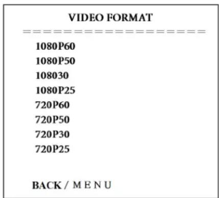
Video Formats: Select from the available formats:
1080P60, 1080P50, 1080P30, 1080P25, 720P60, 720P50, 720P30, 720P25
BACK/MENU: The [MENU] key returns to the previous menu
RESET OPTION
From the MAIN MENU, move the pointer to the
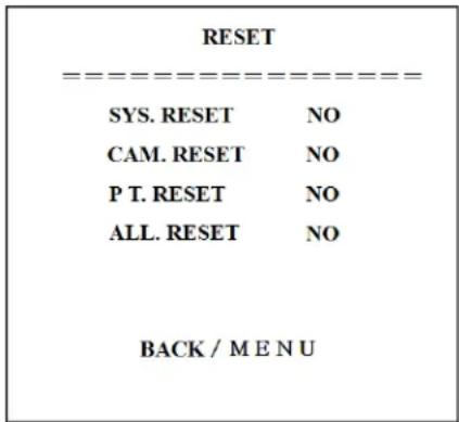
SYS. RESET: System reset:
Protocol: VISCA; Address: 1; baud rate:9600; RS485:Off
CAM. RESET: Camera parameter reset
PT. RESET: power action:
Off; speed by zone: On; mount mode: Up; IR move speed:16; IR zoom speed: 7;MIN.SPEED 0;SCAN. SPEED 10
ALL RESET: reset above 3 items to factory default
BACK/MENU: The [MENU] key returns to the previous menu
HELP OPTION
From the MAIN MENU, move the pointer to the
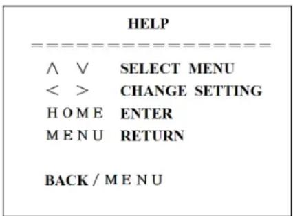
DESCRIPTION:
This screen tells how the keys on the IR Remote are used in the OSD Menu system. The Arrow, Home and Menu keys are shown:
BACK/MENU: The [MENU] key returns to the previous menu
Exit Option
From the MAIN MENU, press the [MENU] key again to enter the EXIT screen. This screen presents the option to save and exit the settings menus, or to exit without saving, as shown:
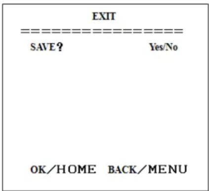
SAVE: To save settings: Yes/No
OK/HOME: The [HOME] key exits the menu system
BACK/MENU: The [MENU] key returns to the Main menu
COM Control of the Camera
In normal working mode, the UNITE camera is able to be controlled via RS-232C/RS485 command (VISCA IN). The parameters of the RS232C/RS485 COM are as follows:
| Parameter Description | |
| Baud Rate 2400/4800/9600/115200 bit/sec. | |
| Start Bit 1 bit | |
| Data Bit 8 bit | |
| Stop Bit 1 bit | |
| Code None | |
When the camera is first connected to power, the camera initializes by moving to the down left, then back to middle, with the farthest zoom rate in the auto focus and auto iris mode. After initialization, the camera moves to the preset No. 0 or 1 if it is established. Then the users can control the camera via serial command.
VISCA PROTOCOL
PART 1: CAMERA RETURN COMMAND
z = Camera Address + 8
| ACK/Completion Message | ||
| Command Packet Note | ||
| ACK z0 41 FF Returned when the command is accepted. | ||
| Completion z0 51 FF Returned when the command has been executed. | ||
| Error Message | ||
| Command Packet Note | ||
| Syntax Error z0 60 02 FF Returned when the command format is different or when a command with illegal command parameters is accepted | ||
| Command Not Executable | z0 61 41 FF Returned when a command cannot be executed due to current conditions. For example, when commands controlling the focus manually are received during auto focus. | |
PART 2: CAMERA CONTROL COMMAND
y=x+8 , where x = the camera address you want to control.
| Command Function | Command Packet Note | ||
| AddressSet Broadcast 88 | 30 01 FF Address setting | ||
| IF_Clear Broadcast 88 01 | 00 01 FF I/F Clear | ||
| CommandCancel 8x 21 FF | |||
| CAM_Power | On 8x 01 04 00 02 FF | Power ON/OFF | |
| Off 8x 01 04 00 03 FF | |||
| CAM_Zoom | Stop 8x 01 04 07 00 FF | ||
| Tele(Standard) 8x 01 04 07 02 FF | |||
| Wide(Standard) 8x 01 04 07 03 FF | |||
| Tele(Variable) | 8x 01 04 07 2p FF | p = 0 (low) - 7(high) | |
| Wide(Variable) 8x 01 04 07 3p FF | |||
| Direct | 8x 01 04 47 0p 0q 0r 0s FF | pqrs: Zoom Position | |
| DirectSpeed | 81 0A 04 47 0V 0p 0q 0r 0s FF | V:Speed 0 (low) - 7 (high)pqrs: Zoom Position | |
| CAM_Focus | Stop 8x 01 04 08 00 FF | ||
| Far(Standard) | 8x 01 04 08 02 FF | ||
| Near(Standard) | 8x 01 04 08 03 FF | ||
| Direct | 8x 01 04 48 0p 0q 0r 0s FF | pqrs: Focus Position | |
| One Push AF | 8x 01 04 18 01 FF | ||
| CAM_ZoomFocus | Direct | 8x 01 04 47 0p 0q 0r 0s0t 0u 0v 0w FF | pqrs: Zoom Positiontuvw: Focus Position |
| CAM_WB | Auto | 8x 01 04 35 00 FF | |
| Indoor | 8x 01 04 35 01 FF | ||
| Outdoor | 8x 01 04 35 02 FF | ||
| OnePush | 8x 01 04 35 03 FF | ||
| Manual | 8x 01 04 35 05 FF | ||
| CAM_RGain | Reset | 8x 01 04 03 00 FF | Manual Control of R Gain |
| Up 8x 01 04 03 02 FF | |||
| Down | 8x 01 04 03 03 FF | ||
| Direct | 8x 01 04 43 00 00 0p 0q FF | pq: R Gain | |
| CAM_Bgain | Reset | 8x 01 04 04 00 FF | Manual Control of B Gain |
| Up 8x 01 04 04 02 FF | |||
| Down | 8x 01 04 04 03 FF | ||
| Direct | 8x 01 04 44 00 00 0p 0q FF | pq: B Gain | |
| Command Function | Command Packet Note | ||
| CAM_AE | Full Auto 8x 01 04 39 00 FF Automatic Exposure mode | ||
| Manual 8x 01 04 39 03 FF Manual Control mode | |||
| Shutter priority 8x 01 04 39 0A FF | Shutter Priority Automatic Exposure mode | ||
| Iris priority 8x 01 04 39 0B FF | Iris Priority Automatic Exposure mode | ||
| Bright 8x 01 04 39 0D FF | Bright mode (Manual control) | ||
| CAM_Shutter | Reset 8x 01 04 0A 00 FF | Shutter SettingUp 8x 01 04 0A 02 FF | |
| Down 8x 01 04 0A 03 FF | |||
| Direct 8x 01 04 4A 00 00 0p 0q FF pq: Shutter Position | |||
| CAM_Iris | Reset 8x 01 04 0B 00 FF | Iris SettingUp 8x 01 04 0B 02 FF | |
| Down 8x 01 04 0B 03 FF | |||
| Direct 8x 01 04 4B 00 00 0p 0q FF pq: Iris Position | |||
| CAM_Gain | Reset 8x 01 04 0C 00 FF | Gain SettingUp 8x 01 04 0C 02 FF | |
| Down 8x 01 04 0C 03 FF | |||
| Direct 8x 01 04 0C 00 00 0p 0q FF pq: Gain Position | |||
| CAM_Bright | Direct | 8x 01 04 4D 00 00 0p 0q FF | |
| CAM_ExpComp | On 8x 01 04 3E 02 FF | Exposure Compensation ON/OFF | |
| Off 8x 01 04 3E 03 FF | |||
| Reset 8x 01 04 0E 00 FF | Exposure Compensation Amount Setting | ||
| Up 8x 01 04 0E 02 FF | |||
| Down 8x 01 04 0E 03 FF | |||
| Direct 8x 01 04 4E 00 00 0p 0q FF pq: ExpComp Position | |||
| CAM_Aperture | Reset 8x 01 04 02 00 FF | Aperture Control | |
| Up 8x 01 04 02 02 FF | |||
| Down 8x 01 04 02 03 FF | |||
| Direct 8x 01 04 42 00 00 0p 0q FF pq: Aperture Gain | |||
| CAM_Memory | Reset 8x 01 04 3F 00 0p FF p: Memory Number (=0 to 127) | ||
| Set | 8x 01 04 3F 01 0p FF | ||
| Recall | 8x 01 04 3F 02 0p FF | ||
| CAM_LR_Reverse | On 8x 01 04 61 02 FF | Image Flip Horizontal ON/OFF | |
| Off 8x 01 04 61 03 FF | |||
| CAM_PictureFlip | On 8x 01 04 66 02 FF | Image Flip Vertical ON/OFF | |
| Off 8x 01 04 66 03 FF | |||
Part 2: CAMERA CONTROL COMMAND - Continued
| Command Function | Command Packet Note | ||
| VideoSystem Set 8x01 06 | 35 00 0p FF | P: Video format1:1080P602:1080P504:720P605:720P506:1080P307:1080P258:720P309:720P25 | |
| CAM_IDWrite 8x01 04 22 | 0p 0q 0r 0s FF | pqrs: Camera ID (=0000 to FFFF) | |
| SYS_Menu OFF 8x01 06 | 06 03 FF Turn off the menu | ||
| IR_Receive | On 8x01 06 08 02 FF | IR (remote commander) receive ON/OFF | |
| Off 8x01 06 08 03 FF | |||
| On/Off 8x01 06 08 10 FF | |||
| IR_ReceiveReturn | On 8x01 7D 01 03 00 00 FF IR (remote commander) | receive message via the VISCA communication ON/OFF | |
| Off 8x01 7D 01 13 00 00 FF | |||
| Pan_tiltDrive | Up 8x01 06 01 VV WW | 03 01 FF | VV: Pan speed 0x01 (low speed) to 0x18 (high speed)WW: Tilt speed 0x01 (low speed) to 0x14 (high speed)YYYY: Pan Position (TBD)ZZZZ: Tilt Position (TBD) |
| Down 8x01 06 01 VV WW | W 03 02 FF | ||
| Left 8x01 06 01 VV WW | 01 03 FF | ||
| Right | 8x01 06 01 VV WW 02 03 FF | ||
| Upleft | 8x01 06 01 VV WW 01 01 FF | ||
| Upright | 8x01 06 01 VV WW 02 01 FF | ||
| DownLeft | 8x01 06 01 VV WW 01 02 FF | ||
| DownRight | 8x01 06 01 VV WW 02 02 FF | ||
| Stop | 8x01 06 01 VV WW 03 03 FF | ||
| AbsolutePosition | 8x01 06 02 VV WW0Y 0Y 0Y 0Y 0Z 0Z 0Z FF | ||
| RelativePosition | 8x01 06 03 VV WW0Y 0Y 0Y 0Y 0Z 0Z 0Z FF | ||
| Home | 8x01 06 04 FF | ||
| Reset 8x01 06 05 FF | |||
| Pan-tiltLimitSet | Set | 8x01 06 07 00 0W0Y 0Y 0Y 0Y 0Z 0Z 0Z FF | W:1 UpRight0 DownLeftYYYY: Pan Limit Position (TBD)ZZZZ: Tilt Limit Position (TBD) |
| Clear | 8x01 06 07 01 0W07 0F 0F 0F 07 0F 0F 0F FF | ||
PART 3: INQUIRY COMMAND
y=x+8 , where x = the camera address you want to control.
| Command Command Packet Return Packet Note | |||
| CAM_PowerInq 8x 09 04 00 FF | y0 50 02 FF On | ||
| y0 50 03 FF Off (Standby) | |||
| CAM_ZoomPosInq 8x 09 04 47 FF y0 50 0p 0q 0r 0s FF p qrs: Zoom Position | |||
| CAM_FocusModelInq 8x 09 04 38 FF | y0 50 02 FF Auto Focus | ||
| y0 50 03 FF Manual Focus | |||
| CAM_FocusPosInq | 8x 09 04 48 FF | y0 50 0p 0q 0r 0s FF | pqrs: Focus Position |
| CAM_WBModelInq 8x 09 04 35 FF | y0 50 00 FF Auto | ||
| y0 50 01 FF Indoor mode | |||
| y0 50 02 FF Outdoor mode | |||
| y0 50 03 FF OnePush mode | |||
| y0 50 04 FF ATW | |||
| y0 50 05 FF Manual | |||
| CAM_RGainInq 8x 09 04 43 FF y0 50 00 00 0p 0q FF pq: R Gain | |||
| CAM_BGainInq 8x 09 04 44 FF y0 50 00 00 0p 0q FF pq: B Gain | |||
| CAM_AEModelInq 8x 09 04 39 FF | y0 50 00 FF Full Auto | ||
| y0 50 03 FF Manual | |||
| y0 50 0A FF Shutter priority | |||
| y0 50 0B FF | Iris priority | ||
| y0 50 0D FF | Bright | ||
| CAM_ShutterPosInq | 8x 09 04 4A FF | y0 50 00 00 0p 0q FF | pq: Shutter Position |
| CAM_IrisPosInq | 8x 09 04 4B FF | y0 50 00 00 0p 0q FF | pq: Iris Position |
| CAM_GainPosInq | 8x 09 04 4C FF | y0 50 00 00 0p 0q FF | pq: Gain Position |
| CAM_BrightPosInq | 8x 09 04 4D FF | y0 50 00 00 0p 0q FF | pq: Bright Position |
| CAM_ExpCompModelInq | 8x 09 04 3E FF | y0 50 02 FF On | |
| y0 50 03 FF Off | |||
| CAM_ExpCompPosInq | 8x 09 04 4E FF | y0 50 00 00 0p 0q FF | pq: ExpComp Position |
| CAM_ApertureInq | 8x 09 04 42 FF | y0 50 00 00 0p 0q FF | pq: Aperture Gain |
| CAM_MemoryInq | 8x 09 04 3F FF | y0 50pp FF | pp: Memory number last operated. |
| SYS_MenuModelInq | 8x 09 06 06 FF | y0 50 02 FF On | |
| y0 50 03 FF Off | |||
| CAM_LR_Reverselnq 8x 09 04 61 FF | y0 50 02 FF On | ||
| y0 50 03 FF Off | |||
| CAM_PictureFlipInq | 8x 09 04 66 FF | y0 50 02 FF On | |
| y0 50 03 FF Off | |||
| CAM_IDInq | 8x 09 04 22 FF | y0 50 0p 0q 0r 0s FF | pqrs: Camera ID |
| CAM_VersionInq | 8x 09 00 02 FF | y0 50 ab cd mn pq rs tu vw FF | |
| VideoSystemInq 8x 09 06 23 FF y0 50 0p FF | P: Video format1:1080P602:1080P504:720P605:720P506:1080P307:1080P258:720P309:720P25 | ||
| IR_Receive 8x 09 06 08 FF | y0 50 02 FF On | ||
| y0 50 03 FF Off | |||
| IR_ReceiveReturn | y0 07 7D 01 04 00 FF Power ON/OFF | ||
| y0 07 7D 01 04 07 FF Zoom tele/wide | |||
| y0 07 7D 01 04 38 FF AF On/Off | |||
| y0 07 7D 01 04 33 FF CAM Backlight | |||
| y0 07 7D 01 04 3F FF CAM Memory | |||
| y0 07 7D 01 06 01 FF Pan_tiltDrive | |||
| Pan-tiltMaxSpeedInq 8x 09 06 | 11 FF y0 50 ww zz FF | ww: Pan Max Speedzz: Tilt Max Speed | |
| Pan-tiltPosInq 8x 09 06 12 FF | y0 50 0w 0w 0w 0w0z 0z 0z 0z FF | www: Pan Positionzzzz: Tilt Position | |
PELCO-D: PROTOCOL COMMAND LIST
x = Camera Address
| Function Byte1 | Byte2 | Byte3 | Byte4 | Byte5 | Byte6 | Byte7 | |||
| Up | 0xFF | Address | 0x00 | 0x08 | Pan Speed | Tilt Speed | SUM | ||
| Down | 0xFF | Address | 0x00 | 0x10 | Pan Speed | Tilt Speed | SUM | ||
| Left | 0xFF | Address | 0x00 | 0x04 | Pan Speed | Tilt Speed | SUM | ||
| Right | 0xFF | Address | 0x00 | 0x02 | Pan Speed | Tilt Speed | SUM | ||
| Upleft | 0xFF | Address | 0x00 | 0x0C | Pan Speed | Tilt Speed | SUM | ||
| Upright | 0xFF | Address | 0x00 | 0x0A | Pan Speed | Tilt Speed | SUM | ||
| DownLeft | 0xFF | Address | 0x00 | 0x14 | Pan Speed | Tilt Speed | SUM | ||
| Upleft | 0xFF | Address | 0x00 | 0x0C | Pan Speed | Tilt Speed | SUM | ||
| Zoom In | 0xFF | Address | 0x00 | 0x20 | 0x00 | 0x00 | SUM | ||
| Zoom Out | 0xFF | Address | 0x00 | 0x40 | 0x00 | 0x00 | SUM | ||
| Focus Far | 0xFF | Address | 0x00 | 0x80 | 0x00 | 0x00 | SUM | ||
| Focus Near | 0xFF | Address | 0x01 | 0x00 | 0x00 | 0x00 | SUM | ||
| Set Preset | 0xFF | Address | 0x00 | 0x03 | 0x00 | Preset ID | SUM | ||
| Clear Preset | 0xFF | Address | 0x00 | 0x05 | 0x00 | Preset ID | SUM | ||
| Call Preset | 0xFF | Address | 0x00 | 0x07 | 0x00 | Preset ID | SUM | ||
| Query Pan Position | 0xFF | Address | 0x00 | 0x51 | 0x00 | 0x00 | SUM | ||
| Query Pan Position Response | 0xFF Address | 0x00 0x59 Value High | Byte | Value Low Byte | SUM | ||||
| Query Tilt Position | 0xFF | Address | 0x00 | 0x53 | 0x00 | 0x00 | SUM | ||
| Query Tilt Position Response | 0xFF Address | 0x00 0x5B Value High | Byte | Value Low Byte | SUM | ||||
| Query Zoom Position | 0xFF | Address | 0x00 | 0x55 | 0x00 | 0x00 | SUM | ||
| Query Zoom Position Response | 0xFF Address | 0x00 0x5D Value High | Byte | Value Low Byte | SUM | ||||
PELCO-P: PROTOCOL COMMAND LIST
x = Camera Address
| Function Byte1 | Byte2 | Byte3 | Byte4 | Byte5 | Byte6 | Byte7 | Byte8 | |||
| Up 0xA0 Address 0 | 0x00 | 0x08 | Pan | Speed | Tilt Speed | 0xAF | XOR | |||
| Down | 0xA0 | Address | 0x00 | 0x10 | 0x10 | Pan Speed | Tilt Speed | 0xAF | XOR | |
| Left | 0xA0 | Address | 0x00 | 0x04 | 0x04 | Pan Speed | Tilt Speed | 0xAF | XOR | |
| Right | 0xA0 | Address | 0x00 | 0x02 | 0x02 | Pan Speed | Tilt Speed | 0xAF | XOR | |
| Upleft | 0xA0 | Address | 0x00 | 0x0C | 0x0C | Pan Speed | Tilt Speed | 0xAF | XOR | |
| Upright | 0xA0 | Address | 0x00 | 0x0A | 0x0A | Pan Speed | Tilt Speed | 0xAF | XOR | |
| DownLeft | 0xA0 | Address | 0x00 | 0x14 | 0x14 | Pan Speed | Tilt Speed | 0xAF | XOR | |
| DownRight | 0xA0 | Address | 0x00 | 0x12 | 0x12 | Pan Speed | Tilt Speed | 0xAF | XOR | |
| Zoom In | 0xA0 | Address | 0x00 | 0x20 | 0x20 | 0x00 | 0x00 | 0xAF | XOR | |
| Zoom Out | 0xA0 | Address | 0x00 | 0x40 | 0x40 | 0x00 | 0x00 | 0xAF | XOR | |
| Focus Far | 0xA0 | Address | 0x00 | 0x80 | 0x80 | 0x00 | 0x00 | 0xAF | XOR | |
| Focus Near | 0xA0 | Address | 0x01 | 0x00 | 0x00 | 0x00 | 0x00 | 0xAF | XOR | |
| Set Preset | 0xA0 | Address | 0x00 | 0x03 | 0x03 | 0x00 | Preset ID | 0xAF | XOR | |
| Clear Preset | 0xA0 | Address | 0x00 | 0x05 | 0x05 | 0x00 | Preset ID | 0xAF | XOR | |
| Call Preset | 0xA0 | Address | 0x00 | 0x07 | 0x07 | 0x00 | Preset ID | 0xAF | XOR | |
| Query Pan Position | 0xA0 | Address | 0x00 | 0x51 | 0x51 | 0x00 | 0x00 | 0xAF | XOR | |
| Query Pan Position Response | 0xA0 Address 0x00 0x59 Value | High Byte | Value Low Byte | 0xAF | XOR | |||||
| Query Tilt Position | 0xA0 | Address | 0x00 | 0x53 | 0x53 | 0x00 | 0x00 | 0xAF | XOR | |
| Query Tilt Position Response | 0xA0 | Address | 0x00 | 0x5B | 0x5B | Value High Byte | Value Low Byte | 0xAF | XOR | |
| Query Zoom Position | 0xA0 | Address | 0x00 | 0x55 | 0x00 | 0x00 | 0xAF | XOR | ||
| Query Zoom Position Response | 0xA0 Address 0x00 0xD Value | High Byte | Value Low Byte | 0xAF XOR | ||||||
Troubleshooting the Camera
CAMERA MAINTENANCE
• If camera is not used for long time, turn off power adapter switch and AC plug.
• Use a soft cloth or tissue to clean the camera cover.
- Use a soft cloth to clean the lens; Use neutral cleanser if the lens is badly smeared. Do not use a strong or corrosive cleanser that could damage the lens.
CAMERA MISUSE
- Do not use camera to view extremely bright objects, such as direct sunlight, lamplight etc.
- Do not use camera in variable light environments, otherwise the image will not stabilize.
- Do not operate in strong electromagnetic environments.
• Light levels below the cameras rating will give substandard images.
TROUBLESHOOTING
No Image
- Check whether the power cord and voltage are correct, and the power indicator light is ON.
- Turn off the power supply and on again to check whether the camera can auto-configure.
- Check the switches at the bottom of the camera and make sure SW1 and SW2 two are ON in working mode.
- Check that all wires are connected correctly.
Abnormal Image Displayed
- Check whether the video connecting wires are solidly connected in their sockets and all other camera wiring is correct.
- If the camera can only work at one focus, and other positions can not be focused, change the position of the camera to see if this condition still exists. If yes, it may be caused by camera control drive system trouble.
Image Dithering when at Maximum Zoom
Check whether the camera is on a fixed, solid surface, or if there is a vibrating mechanical object nearby that is shaking the camera.
Remote Controller
- Make sure the batteries are fresh and correctly installed.
- Check the camera operation mode is correct.
Compliance
ELECTRICAL SAFETY ADVISORY
This equipment uses DC power supplied from an external source which can be subjected to electrical surges, typically lightning transients which are very destructive to customer terminal equipment. The warranty for this equipment does not cover damage caused by electrical surge or lightning transients. To reduce the risk of this equipment becoming damaged it is suggested that the customer consider installing a surge arrestor.
Any modifications to the device without express authorization from ClearOne is prohibited as per 47CFR15.21 and could void the users authority to operate the device.
COMPLIANCE DETAILS
FCC COMPLIANCE
FCC Part 15: This device complies with FCC Part 15 regulations for a Class A device.
» NOTE: This Class A device complies with Part 15 of the FCC rules and Canadian ICES-003. Operation is subject to the following two conditions: (1) this device may not cause harmful interference, and (2) this device must accept any interference received, including interference that may cause undesired operation.
EUROPEAN COMPLIANCE
Details on European equipment compliance can be found on the ClearOne website.
Service and Support
If you need assistance setting up or operating your product, please contact us. We welcome your comments so we can continue to improve our products and better meet your needs.
TECHNICAL SUPPORT
Telephone: 1.800.283.5936
E-mail:tech.support@ClearOne.com
Web site: www.ClearOne.com
SALES
Telephone: 1.800.707.6994
E-mail:sales@ClearOne.com
TECHSALES
Telephone: 1.800.705.2103
E-mail:techsales@ClearOne.com
PRODUCT RETURNS
All product returns require a Return Material Authorization (RMA) number. Contact ClearOne Technical Support before returning your product. Make sure you return all the items and packing materials that originally shipped with your product.
HEADQUARTERS:
Salt Lake City, UT USA
5225 Wiley Post Way
Suite 500
Salt Lake City, UT 84116
Tel: +801.975.7200
Toll Free: +800.945.7730
Sales: +800.707.6994
Fax: +801.303.5711
e-mail: sales@clearone.com
Europe & Oceana
Tel: +44.1454.616.977
e-mail: global@clearone.com
Asia Pacific
Tel: +852.3590.4526
e-mail: global@clearone.com
Latin America
Tel: +801.974.3621
e-mail: global@clearone.com
Middle East
Tel: +852.3590.4526
e-mail: global@clearone.com
Technical Support
Tel: +800.283.5936
e-mail: tech.support@clearone.com

- Table of Contents
- INTRODUCTION
- INSTALLATION
- CAMERA PHYSICAL DESCRIPTION
- MENU CONTROL OF THE CAMERA
- COM CONTROL OF THE CAMERA
- TROUBLESHOOTING THE CAMERA CONTROL OF THE CAMERA
- COMPLIANCE
- SERVICE AND SUPPORT
- PREFACE
- WARNING NOTES
- FEATURES
- PARTS INCLUDED
- CONNECTIONS
- SETUP
- RS232/DB9 INTERFACE
- Camera Operation Using the Remote
- MAIN SCREEN
- SYSTEM OPTION
- CAMERA OPTION
- Exposure Submenu
- Color Submenu
- LEN Submenu
- NR Submenu
- PT OPTION (PAN/TILT)
- FORMAT OPTION
- RESET OPTION
- HELP OPTION
- DESCRIPTION:
- Exit Option
- VISCA PROTOCOL
- PELCO-P: PROTOCOL COMMAND LIST
- Troubleshooting the Camera
- CAMERA MAINTENANCE
- CAMERA MISUSE
- TROUBLESHOOTING
- No Image
- Abnormal Image Displayed
- Image Dithering when at Maximum Zoom
- Remote Controller
- ELECTRICAL SAFETY ADVISORY
- COMPLIANCE DETAILS
- FCC COMPLIANCE
- EUROPEAN COMPLIANCE
- TECHNICAL SUPPORT
- SALES
- TECHSALES
- PRODUCT RETURNS
- HEADQUARTERS:
- Salt Lake City, UT USA
- Europe & Oceana
- Asia Pacific
- Latin America
- Middle East
Brand : ClearOne
Model : UNITE 100
Category : Video Conferencing System