9606 G - Network card / adapter Microsemi - Free user manual and instructions
Find the device manual for free 9606 G Microsemi in PDF.


| Product Type | Power over Ethernet Midspan (PoE Injector) |
| Model | PD-9606G/ACDC/M (Microsemi 9606 G) |
| Number of Ports | 6 ports (Data In and Data & Power Out) |
| Data Rate | 10/100/1000BASE-T (Gigabit Ethernet) |
| Power Standard | PoH (HDBaseT) and IEEE 802.3at (PoE+) |
| Maximum Power per Port | 95 W (4-pair, Twin High PSE) |
| Total Output Power | 950 W max |
| Input Voltage | 100-240 VAC, 50/60 Hz |
| Input Current | 12 A max at 100 VAC, 6 A max at 240 VAC |
| Nominal Output Voltage | 50-57 VDC |
| Dimensions (H x W x D) | 44 × 435 × 271 mm (1.75 × 17.2 × 10.7 inches) |
| Weight | 4.8 kg (10.6 lb) |
| Operating Temperature | 0° to +40°C (32° to 104°F) |
| Storage Temperature | -20° to +70°C (-4° to 158°F) |
| Humidity | 10% to 90% (non-condensing) |
| Management | Remote via Web, SNMPv3, or PowerView Pro software |
| Power Backup/Redundancy | Supports external RPS (PD-RPS-1000) and midspan-to-midspan redundancy |
| Safety Compliance | UL/cUL (CSA/UL 60950-1), GS (IEC60950-1), CE |
| EMC Compliance | FCC Part 15 Class B, EN 55022 Class B, EN 55024, ICES-003 Class B |
| Indicators | Power LED (green), port LEDs (green/yellow for 4-pair/2-pair power) |
| Connectors | RJ-45 for data/power, USB console, DC terminal block, RPS COM D-sub |
| Installation | 19-inch rack mountable (brackets included) or shelf mount |
| Maintenance and Cleaning | No user-serviceable parts; clean exterior with dry cloth; do not use liquids |
| Repairability | No user-serviceable parts; contact authorized service for repairs |
Frequently Asked Questions - 9606 G Microsemi
User questions about 9606 G Microsemi
0 question about this device. Answer the ones you know or ask your own.
Ask a new question about this device
Download the instructions for your Network card / adapter in PDF format for free! Find your manual 9606 G - Microsemi and take your electronic device back in hand. On this page are published all the documents necessary for the use of your device. 9606 G by Microsemi.
USER MANUAL 9606 G Microsemi
Microsemi PD96XX Series
PD-9606G & PD-9612G
PD-RPS-1000
natural_image
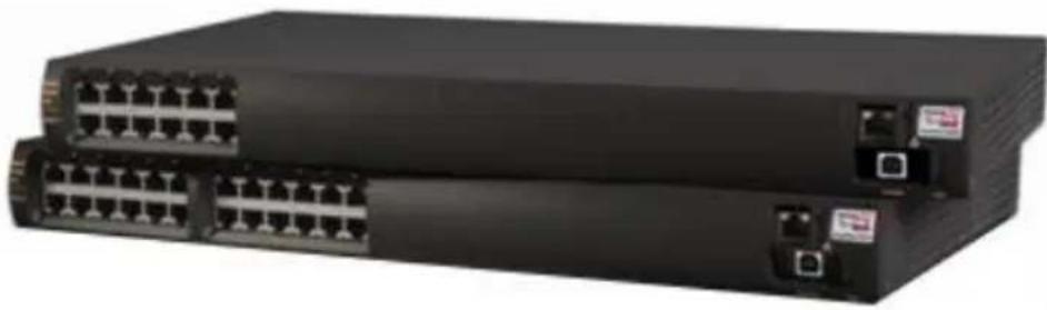
Two black networking devices with 16 Ethernet ports, no visible text or labelsUser Guide
Note:
The information contained herein is believed to be accurate and reliable at the time of printing. However, due to ongoing product improvements and revisions, Microsemi cannot accept responsibility for inadvertent errors, inaccuracies, subsequent changes, or omissions of printed material.
Microsemi reserves the right to make changes to products and to their specifications as described in this document, at any time, without prior notice. Do not photocopy or reproduce this material without permission.
Disclaimer
Microsemi assumes no responsibility or liability arising from the use of Midspans, as described herein, nor does it convey any license under its patent rights or the rights of others. Applications that are described herein for any of these products are for illustrative purposes only. Microsemi makes no representation or warranty that such applications will be suitable for the specified use without further testing or modification.
Note:
The information in this guide refers to PD-96xx series of Power over Ethernet Midspans, unless otherwise stated.
Note that Midspan is designed for indoor use only.
© Microsemi Corp.
All rights reserved.
This document is subject to change without notice.
Contents
1 FRONT MATERIAL....5
1.1 Model Numbers Definition: 5
1.2 Electrical Compatibility Approvals .... 5
1.3 Safety Standard Approvals....5
1.4 CE Marking 5
2 SAFETY INFORMATION......6
2.1 General Guidelines 6
2.2 Warnings....6
2.3 Power Cord 7
2.4 Power Cord Specifications by Country 7
3 ABOUT THE POWER OVER ETHERNET MIDSPAN....9
3.1 10/100/1000BASE-TX Ports Definition.... 10
3.1.1 Data Input Ports 10
3.1.2 Data and Power Output Ports 10
3.2 Indicators....11
3.2.1 Power Indicator LED 11
3.2.2 Port Indications....11
3.3 Connectors....13
4 POWER OVER ETHERNET MIDSPAN INSTALLATION....15
4.1 Background Information 15
4.2 Verifying Kit Contents.... 15
4.3 Rack Mounting Brackets 16
4.4 Installation Factors....16
Microsemi.
4.5 Connecting Ethernet Cables....17
4.6 Connecting Power Cables....17
4.7 Powering Up the Unit 18
5 TROUBLESHOOTING....19
5.1 Preliminary Steps....19
5.2 Troubleshooting Steps....20
6 SPECIFICATIONS....22
6.1 Physical Specifications 22
6.2 Environmental Specifications....22
6.3 Electrical Specifications 23
7 MICROSEMI'S POWERVIEW PRO 24
8 POWER BACKUP AND POWER REDUNDANCY CONNECTION ......26
8.1 Power Redundancy....26
8.2 Power Backup....26
8.3 Connectors....27
8.4 Connecting Backup and Redundancy Connectors....28
8.5 Power Backup and Power Redundancy Indications....30
1 Front Material
1.1 Model Numbers Definition:
- PD-96xxG/ACDC/M: 4 Pairs AC and DC Input family, where:
- xx: Represents number of ports (6 or 12)
- AC: Midspan has AC input
- DC: Midspan has DC input, current sharing, and power backup features between two Midspans
- M: Midspan includes PowerView Pro (refer to Section 7)
- PD-RPS-AAAA: Redundant Power Supply, where AAAA represents available power in Watts.
1.2 Electrical Compatibility Approvals
Microsemi 96xxG series complies with the following standards:
■ FCC Part 15; class UTP cabling
■ EN 55022 (CISPR 22); class B with UTP cabling
■ EN 55024 (CISPR 24)
■ Canadian ICES-003, class B
1.3 Safety Standard Approvals
Microsemi meets the following safety standards:
■ UL/cUL per CSA/UL 60950-1
■ GS mark per IEC60950-1
1.4 CE Marking
CE marking on this product indicates this product complies with 89/336/EEC (EMC Directive) and 73/23/EEC (Low Voltage Directive).
2 Safety Information
Read the following safety information before using your Power over Ethernet Midspan unit.
2.1 General Guidelines
Read the following safety information before carrying out any installation, removal, or maintenance procedure on the Power over Ethernet Midspan. Warnings contain directions to be followed for the safety of personal and product. Follow all directions carefully.
2.2 Warnings
- Read installation instructions in Section 4 before connecting Power over Ethernet Midspan to its power source.
- Read instructions in Section 4 before connecting Midspan-to-Midspan power backup.
- Midspan must use a grounded power cord, as defined in Section 2.3.
- This product relies on the building installation for short-circuit (over-current) protection. Use only a fuse or circuit breaker not higher than 15A for 120VAC (U.S.), or 10A for 230VAC (international).
- Do not work on the system, connect, or disconnect cables during periods of lightning.
- A voltage mismatch can cause equipment damage and can pose a fire hazard. If voltage indicated on the label is different from power outlet voltage, do not connect Power over Ethernet Midspan to this outlet.
- For shelf-mounted equipment, verify surface is stable and strong enough to support equipment. Do not stack more than four Power over Ethernet Midspan units.
- When disposing this product, follow all local laws and regulations.
- "DATA" and "DATA & POWER" ports of the Power over Ethernet Midspan are shielded RJ-45 data sockets. They cannot be used as Plain Old Telephone Service (POTS) sockets. Only connect RJ-45 data connectors to these sockets.
■ Associated Ethernet wiring shall be limited to the inside of the building.
2.3 Power Cord
In case power cord is replaced, replacement must meet local requirements.
- To ensure a reliable connection to an AC mains supply, equipment provides an appliance IEC60320 inlet used for connecting a detachable power supply cord.
■ Power socket outlet must be located near Midspan and easily accessible. The only way of removing power from unit is by disconnecting the power cord from the outlet - This unit operates under SELV (Safety Extra Low Voltage) conditions, according to EN60950-1/IEC60950-1. Conditions are maintained only if the equipment to which unit is connected also operates under SELV conditions.
2.4 Power Cord Specifications by Country
U.S.A. and Canada
- Cord must be UL-approved or CSA certified.
■ Minimum specification for flexible cord is:
○ No. 18 AWG
○ Type SV or SJ
○ Three-conductor
- Cord set must have a rated current capacity of at least 13A for PD-9612G/ACDC/M, PD-9606G/ACDC/M;
- Attachment plug must be an earth-grounding type with a NEMA 5-15P (15A, 125V) or NEMA 6-15P (15A, 250V) configuration.
Denmark
Supply plug must comply with section 107-2-D1, standard DK2-1a or DK2-5a.
Switzerland
Supply plug must comply with SEV/ASE 1011.
France and
IT supplies cannot power this unit. If your supplies are an IT type, unit must be powered by 230V (2P+T) via an isolation transformer with a 1:1 ratio, and with secondary connection point labeled Neutral and connected directly to ground.
Peru
U.K
Power over Ethernet Midspan is covered by General Approval NS/G/12345/J/100003, for indirect connection to a public telecommunications system.
3 About the Power over Ethernet Midspan
Microsemi's family of Power over Ethernet Midspans 96xx inject power over data-carrying Ethernet cabling. Employing these devices reduces the need for AC outlets, local UPS and AC/DC adapters near PDs.
PD-9606G/9612G Midspans support 6 and 12 ports respectively, in a 10/100/1000BaseTx Ethernet network, over TIA/EIA-568 category 5/5e/6 cabling. 96xxG family can provide up to 95W according to the new PoH (Part of HDBaseT) standard. 96xxG series implements a Twin High (TH) PSE system, delivering 47.5W over 2 pairs (total 95W). DC power is fed over both spare and data pairs of wires within a cable (1/2, 3/6, 4/5, and 7/8) to terminal units.
RPS family can provide backup or additional power to PD-96xxG products.
Power over Ethernet Midspan normally powers devices that are Power over Ethernet enabled or are equipped to receive power over Ethernet. These devices are called Powered Devices (PDs).
Features of the Power over Ethernet Midspan include:
■ Safe and reliable power over an existing Ethernet infrastructure
■ Remote management using Web control and/or SNMPv3
■ Highest level of network security
■ Safe solution that protects network infrastructure
■ Standards compliant: PoH and 802.3at
■ Provides safe Power + Data over a single RJ45 cable
3.1 10/100/1000BASE-TX Ports Definition
The following sections detail 96xxG ports and their functions.
3.1.1 Data Input Ports
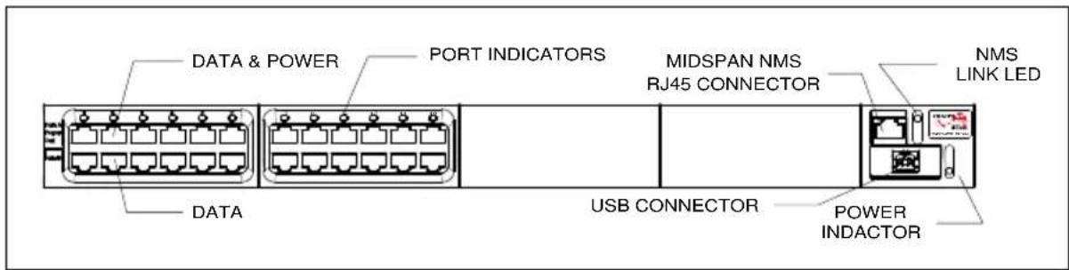
Midspan has 6 or 12 10/100/1000Base-T Data In ports, located on PoE front panel (Figure 3-1), configured in a non-crossover manner (straight-wired).
These ports are designed to carry Ethernet data only (Tx/Rx) over:
- Standard 4-wire pairs (pins 1/2, 3/6, 4/5 and 7/8) (1000Base-T)
■ 2-wire pairs (pins 1/2 and 3/6) (10/100Base-T)
3.1.2 Data and Power Output Ports
Midspan has 6 or 12 10/100/1000Base-T Data & Power Out ports, located on the front panel (see Figure 3-1). These ports are configured in a non-crossover manner (straight-wired) and carry Ethernet data over:
- Standard 4-wire pairs (pins 1/2, 3/6, 4/5, and 7/8) (1000Base-T)
■ 2-wire pairs (pins 1/2 and 3/6) (10/100Base-T) - PD-96xxG series carry DC power over 4-wire pairs (pins 4/5, 7/8 and pins 1/2, 3/6)
Power over Ethernet Midspan is not a repeater; therefore maximum distance from Ethernet switch must not exceed 100 meters (328ft). Power over Ethernet Midspan is guaranteed to work only within this distance, as specified in IEEE 802.3 AT standard.
text_image
DATA & POWER PORT INDICATORS MIDSPAN NMS RJ45 CONNECTOR NMS LINK LED DATA USB CONNECTOR POWER INDACTORFigure 3-1: Power over Ethernet Midspan, Front View (PD-9612G)
3.2 Indicators
A set of indicators displays the status of the Power over Ethernet Midspan and its ports. Refer to Table 3-1 and Table 3-1 for details about status information during operation.
3.2.1 Power Indicator LED
Power Indicator LED on front panel displays power status of Power over Ethernet Midspan. When this LED is illuminated in green, Midspan is receiving AC power. For additional information refer to Table 3-1.
3.2.2 Port Indications
The following sections detail PD-96xxG port indicators.
3.2.2.1 PD-96xxG Midspan Series:
One bi-color (green and yellow) indicator per port displays port status:
- Green indicates terminal unit (PD) has been identified as "Power over Ethernet Enabled"; it is active and receiving power over 4-wire pairs.
- Yellow indicates terminal unit (PD) has been identified as "Power over Ethernet Enabled"; it is active and receiving power over 2-wire pairs.
- Blinking green indicates port does not supply power and is inactive.
Note PDs that are not PoE-enabled devices are not powered by Midspan.
Table 3-1: Power Status Indications
| Indicator | Color | Main Power Status | Remarks |
| Power Indicator | Off | Power supply unit is unplugged | |
| Green | Power input is active | Power supply voltage is within limits | |
| Green light blinks once every second (only if power backup is connected) | Midspan power supply failure (disconnected or out of voltage range) | Unit receives backup power and continues to function normally. Maintenance measures should be taken whenever possible. |
Table 3-2: Port Status Indications PD-96xx Series
| Port LED Color | Port Load Conditions | Port Voltage |
| Off | Inactive load or unplugged port | Power to port is disconnected. No DC voltage present on port output lines. |
| Green | Active load is plugged in and complies with normal load conditions. | Continuous nominal DC voltage is present according to 4-Pairs configuration. |
| Yellow | Active load is plugged in and complies with normal load conditions. | Continuous nominal DC voltage is present on 2-wire pairs. |
| Green blinks once every second | Overload or short circuit | Power to port is disconnected.No DC voltage is present on port output lines. |
| Green blinks once every 0.5 seconds | Valid load.Total aggregated power exceeds predefined power budget | Power is not connected to port.No DC voltage is present on port output lines |
3.3 Connectors
On Midspan's front panel there's a Console port. Using a standard USB cable, users can connect a terminal to this port and load software.
Note: USB connection requires 'CP210x Driver.exe' installation. Supplied CD provides the driver.
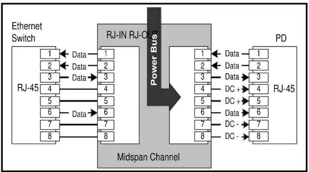
Console port is set to 38,400-baud for managed units and 19,200-baud for unmanaged units, 8 data bits, no parity, and 1 stop bit. Figure 3-2 displays pin connections for this connector.
flowchart
graph LR
    subgraph RJ-45
        A1["1"] -->|Data| B1["1"]
        A2["2"] -->|Data| B2["2"]
        A3["3"] -->|Data| B3["3"]
        A4["4"] -->|Data| B4["4"]
        A5["5"] -->|Data| B5["5"]
        A6["6"] -->|Data| B6["6"]
        A7["7"] -->|Data| B7["7"]
        A8["8"] -->|Data| B8["8"]
    end

    subgraph RJ-IN RJ-OUT
        C1["1"] --> D1["1"]
        C2["2"] --> D2["2"]
        C3["3"] --> D3["3"]
        C4["4"] --> D4["4"]
        C5["5"] --> D5["5"]
        C6["6"] --> D6["6"]
        C7["7"] --> D7["7"]
        C8["8"] --> D8["8"]
    end

    subgraph PD
        D1 --> E1["1"]
        D2 --> E2["2"]
        D3 --> E3["3"]
        D4 --> E4["4"]
        D5 --> E5["5"]
        D6 --> E6["6"]
        D7 --> E7["7"]
        D8 --> E8["8"]
    end

    RJ-45 -->|Ethernet Switch| RJ-OUT
    style RJ-OUT fill:#f9f,stroke:#333
    style PD fill:#ccf,stroke:#333
Figure 3-2: Connecting to Midspan
Each data port is configured, as shown in Figure 3-2, as data "Pass-Through" ports for all data pins (pins 1, 2, 3, 6, 4, 5, 7, and 8). Make sure you are using cabling of Category 5 or higher.
4 Power over Ethernet Midspan Installation
The following sections describe how to install a Power over Ethernet Midspan.
4.1 Background Information
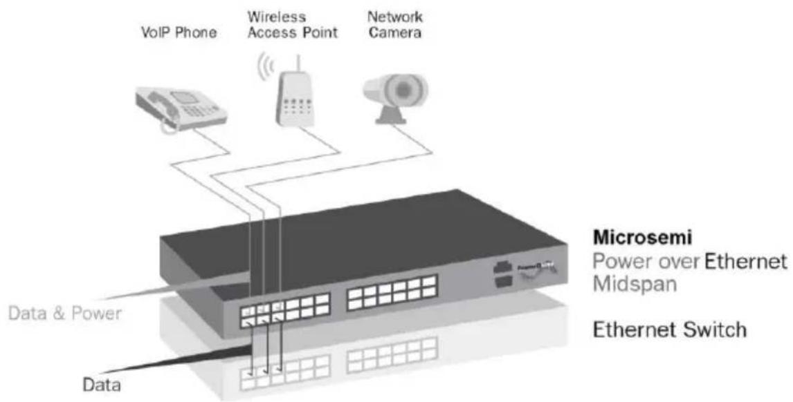
As shown in Figure 4-1, Midspan is connected in series to an Ethernet switch/hub. Switch's data output terminals are connected to Midspan. Midspan delivers power over 4-wire twisted pairs (pins 7/8, 4/5 and pins 1/2, 3/6) in PD-96xxG series of Category 5e cabling, regardless to data quality. Most installations require Midspan to be rack-mounted.
text_image
VoIP Phone Wireless Access Point Network Camera Data & Power Microsemi Power over Ethernet Midspan Ethernet Switch DataFigure 4-1: Typical Installation
4.2 Verifying Kit Contents
Unpack kit and verify the following items are included:
■ Power over Ethernet Midspan
■ Mounting brackets (for 19-inch racks) and a plastic cover
■ Screws for assembling mounting brackets
■ Self-adhesive rubber feet
- User guide
■ Power cord
Before proceeding, record unit's serial number in the rectangle below for future reference. Serial number is found on the information label at the back of the Power over Ethernet Midspan.
Serial Number
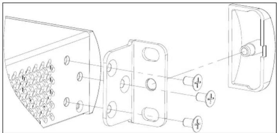
4.3 Rack Mounting Brackets
Midspan comes with 19-inch mounting brackets and screws.
To install Midspan into a 19-inch rack:
- Remove self-adhesive rubber feet from the bottom surface.
- Install brackets using two screws per side.
Note: Rack-mounting screws are not provided.
natural_image
Technical line drawing of a mechanical assembly with multiple components and mounting holes (no text or symbols)Figure 4-2: Installing Mounting Brackets
4.4 Installation Factors
- Elevated Operating Ambient Temperature: If installed in a closed or multi-unit rack assembly, operating ambient temperature in rack environment may be greater than room ambient temperature. Therefore, install
equipment in an environment compatible with manufacturer's maximum rated ambient temperature ( T_mra ).
- Reduced Air Flow: Install equipment in a rack in a manner that does not compromise the amount of airflow required for safe operation of equipment.
- Mechanical Loading: When mounting equipment in rack, ensure mechanical loading is even.
- Circuit Overloading: Take into consideration the connection of equipment to supply circuit and the effect overloading of circuits might have on over-current protection and supply wiring. Appropriate consideration of equipment nameplate ratings must be given when addressing this concern.
- Reliable Grounding (Earthing): Maintain reliable earthing of rack mounted equipment. Pay particular attention to supply connections, other than direct connections to branch circuit (for example, the use of power strips).
4.5 Connecting Ethernet Cables
Ports on Midspan's front panel are configured as "Pass Through" ports for eight (1, 2, 3, 6, 4, 5, 7, 8) conductors of RJ-45 connectors. Use Category 5 cabling when making connections.
-
Connect cables from Ethernet Switch to DATA IN ports (lower row on front panel).
-
Connect cables from PoH or IEEE 802.3at ready terminals (PDs) to corresponding DATA & POWER OUT ports (upper row on front panel).
4.6 Connecting Power Cables
When using an AC source to power Midspan, plug in the provided power cord to back AC connector.
4.7 Powering Up the Unit
Power over Ethernet Midspan has no on/off switch. To apply or remove power from Midspan, insert or remove power cable to receptacle (AC) on the back panel of the unit.
With power applied;
- Midspan powers-up.
■ Internal fan operates.
■ Device runs its Power-On Self-Test (POST), which takes less than 10 seconds. During POST, all ports are disabled and indicators illuminate in the following sequence:
o Port indicators and Power indicators illuminate in green.
- Power indicator remains lit in green; port indicators are off.
Ports are now ready (enabled) for normal operation.
If LEDs are not lit, refer to Troubleshooting on page 19.
5 Troubleshooting
The following sections describe troubleshooting procedures to be used if you encounter any problems with your unit.
5.1 Preliminary Steps
If you have a problem, verify:
■ Power is applied to Midspan.
- A crossover-type Ethernet cable has not been used.
- Ethernet cable from network is connected to DATA port.
- Ethernet cable to PD is connected to DATA & POWER port.
- Cable pairs are attached to their corresponding ports.
5.2 Troubleshooting Steps
This section provides a symptom and resolution sequence to assist in troubleshooting of minor operating problems. If steps given do not solve your problem, do not hesitate to call your local dealer for further assistance. Refer to Table 5-1.
Table 5-1: Troubleshooting Steps
| Symptom | Corrective Steps |
| Midspan does not power up | 1. Make sure power cord is properly connected.2. Verify voltage at power inlet is between 100 and 240VAC.3. Remove and reapply power to device and check indicators during power up sequence. |
| A port indicator is not lit and corresponding PD does not operate. | 1. Verify port is enabled (Midspan did not detect a PD).2. Verify PD is designed for Power over Ethernet operation.3. Verify you are using a standard Category 5/5e/6, straight-wired cable, with four pairs.4. If an external power splitter is in use, replace it with a viable splitter.5. Verify PD is connected to DATA & POWER OUTPUT port.6. Try to reconnect the same PD to a different port on the same Midspan or on another one. If it works, there is probably a faulty output port or RJ-45 connection.7. Verify port shutdown command was not issued via Web management. |
Table 5-1: Troubleshooting Steps
| Symptom | Corrective Steps |
| End device operates, but there is no data link. | 1. Verify port indicator on front panel is continuously lit.2. If an external power splitter is in use, replace it with a viable splitter.3. Verify that for this link you are using a standard UTP/FTP Category 5 straight (non-crossover) cabling, with all four pairs, and that link is 100 meters long or less.4. Try to reconnect the same PD to a different port on the same Midspan or on another one. If it works, there is probably a faulty port or faulty RJ-45 connection. |
6 Specifications
The following sections detail units' specifications.
6.1 Physical Specifications
Dimensions (H x W x D)
44 × 435 × 271 ~mm
(1.75" × 17.2" × 10.7")
| P/N | Weight |
| PD-9612G/ACDC/MPD-9606G/ACDC/MPD-RPS-1000 | 4.8Kg (10.6lb) |
6.2 Environmental Specifications
| Operating TemperatureStorage Temperature | 0° to +40°C (32° to 104°F)-20 to +70°C (-4° to 158°F) |
| Humidity | 10 to 90% (non-condensing) |
6.3 Electrical Specifications
| Parameter | PD-9612G/ACDC/M, PD-9606G/ACDC/M & PD-RPS-1000 |
| AC Input Voltage | 100 to 240VAC at 50/60Hz |
| Input Current @ 100VAC | 12A max |
| Input Current @ 240VAC | 6A max |
| Nominal Output Voltage | 50 to 57VDC |
| Total Output Power | 950W max |
| Maximum Output Power per Port | PD-96XX series 95W |
| Parameter | PD-9612G/ACDC/M, PD-9606G/ACDC/M & PD-RPS-1000 | |
| DC Input Rated Voltage | 53-57 | VDC--- |
| Input DC Maximum Current | 20A | |
7 Microsemi's PowerView Pro
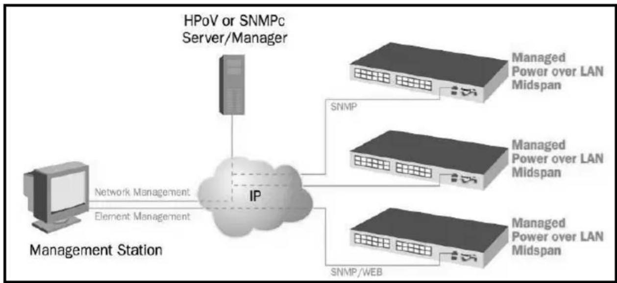
Microsemi's PowerView Pro is a secure remote management system offering real time monitoring and control, with graphical representation, status indicators, and alarms. PowerView Pro manages Midspans via an Internet browser interface or via a Network Management System (NMS). Some of the most important features is remote power enable/disable functionality on each Midspan port, supporting “hard resets” of remote terminals such as WLAN Access Points and VoIP Phones PowerView Pro, and enabling to monitor and control at network and Element levels, as shown in Figure 7-1. For further details, refer to Microsemi's PowerView Web Manager user guide.
flowchart
graph TD
    A["Management Station"] -->|Network Management| B["IP"]
    B --> C["Managed Power over LAN Midspan"]
    B --> D["Managed Power over LAN Midspan"]
    B --> E["Managed Power over LAN Midspan"]
    B --> F["SNMP/WEB"]
    B --> G["SNMP"]
    H["HPoV or SNMPc Server/Manager"] --> B
Figure 7-1: Management Deployment
PowerView Pro provides a number of unique features for Midspan management:
■ Remote Web Management of PoE for monitoring and configuration
- Configuration using graphical representations of remote devices
■ Real time monitoring and configuration with visual status indicators and alarms
Microsemi.
■ Multi-manager capabilities
■ Event and performance data recording
- Runs on a PC platform with Windows graphic user interface (GUI)
8 Power Backup and Power Redundancy Connection
96xxG has two options for ensuring continuous power supply:
■ Power Redundancy
■ Power Backup
8.1 Power Redundancy
Microsemi 's power redundancy mode is available in 96xxG Midspan series. This mode enables internal power supply backup for two Midspans connected to each other. This mode provides seamless failover between two Midspans. If one of the two Midspans' internal power supplies fails, failure is detected automatically and working power supply provides power to Midspan. Both Midspans are ensured continuous uptime and all active ports continue to operate without any effect on connected powered devices.
Power redundancy mode is available in the following midspans:
■ PD-9612G/ACDC/M
■ PD-9606G/ACDC/M
Note: When using power redundancy option, connect together only units that share the same power supply:
■ 1Kw power supply units
○ PD-9612G/ACDC/M
○ PD-9606G/ACDC/M
WARNING:
When connecting power redundancy connectors, make sure AC power in both Midspans is disconnected from AC mains!
8.2 Power Backup
In case one of Midspans' power supplies fails, unit maintains full functionality by using an optional backup power supply.
| Midspan Unit | Redundant Power Supply |
| PD-9612G/ACDC/MPD-9606G/ACDC/M | PD-RPS-1000 |
8.3 Connectors
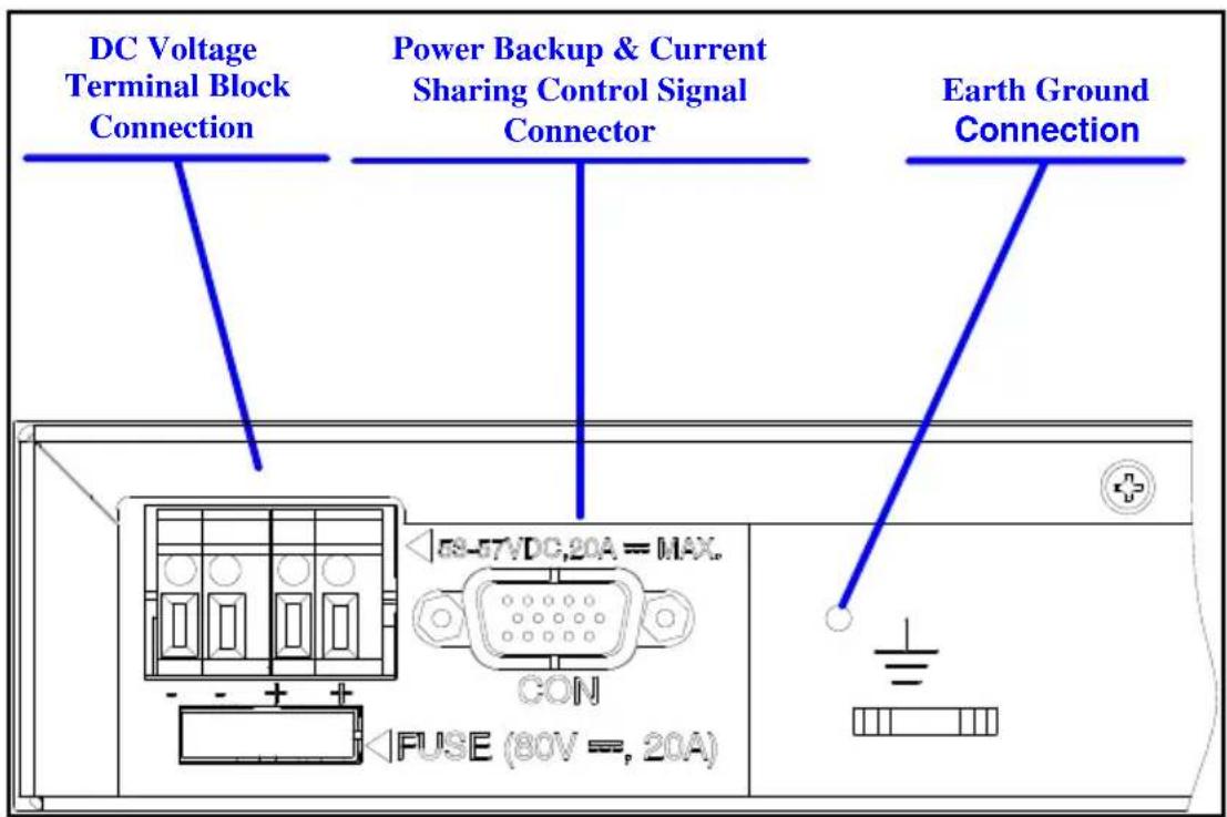
Power backup and power redundancy connectors are located on the back side of the Midspan.
PD-96xxG power backup and power redundancy have two connectors (see Figure 8-1):
■ Power Backup and Power Redundancy Control Signal connector, RPS COM D-Sub: 15 pins, 3 rows female connector.
- DC Voltage Terminal Block Connector has two positive (+) terminals and two negative (-) terminals.
text_image
DC Voltage Terminal Block Connection Power Backup & Current Sharing Control Signal Connector Earth Ground Connection 68-67VDC,20A = MAX. CON FUSE (80V = , 20A)Figure 8-1: PD-96xxG Rear Panel Connectors
8.4 Connecting Backup and Redundancy Connectors
WARNING:
Before connecting one Midspan to another, disconnect both Midspans from AC main.
Implement Power Backup and Power Redundancy modes by using PD-RPS-Cables Cable kit which includes DC Cable and RPS COM.
To connect the connectors:
- Verify Midspans are mounted securely on rack.
- Verify Midspans are not connected to AC mains.
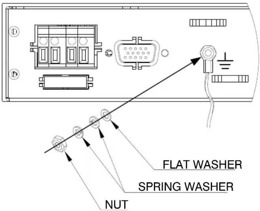
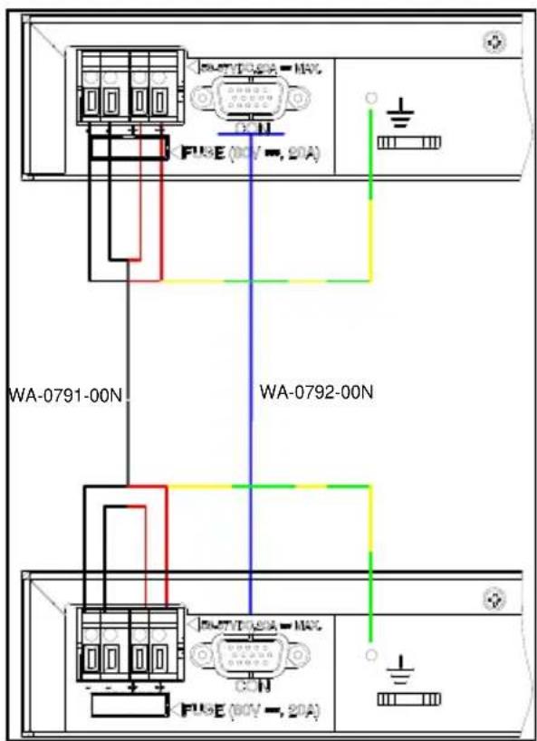
- Connect DC cable; two red wires (+), two black wires(-), and one yellow/green wire, as shown in Figure 8-2.
- Connect RPS COM cable.
- Connect Midspans to AC outlet.
- Verify Power Indicator LED is ON (Green LED).
Note:
When connecting a midspan to midspan or to an RPS unit - Connect the earth ground cable between both units Earth Ground connection.
text_image
FLAT WASHER SPRING WASHER NUTNote:
If Power Indicator LED is not lit, refer to Troubleshooting on page 19.
Note:
RPS functionality can be monitored via NMS as described in Section 8.3.
text_image
WA-0791-00N WA-0792-00N FU8E (10V = , 20A)Figure 8-2: PD-96xxG Rear Panel connections
8.5 Power Backup and Power Redundancy Indications
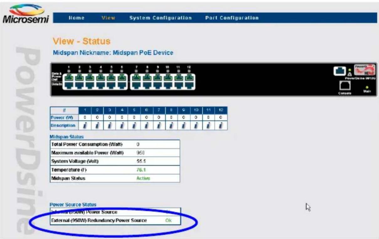
For information on NMS configuration refer to PowerView Pro user guide, catalog number 056-0051-06. During Power Backup and Power Redundancy, NMS View-Status window displays 'Power Source Status' field. 'Power Source Status' field shows both internal and external power supply statuses (green indication for 'OK and red indication for 'Fail').
text_image
Microsemi Home View System Configuration Port Configuration View - Status Midspan Nickname: Midspan PoE Device Data & Power Out PowerIn # 1 2 3 4 5 6 7 8 9 10 11 12 Power (W) 0 0 0 0 0 0 0 0 0 0 0 0 Description # Midspan Status Total Power Consumption (Watt) 0 Maximum available Power (Watt) 960 System Voltage (Volt) 55.5 Temperature (F) 76.1 Midspan Status Active Power Source Status External (800W) Power Source External (950W) Redundancy Power Source OkFigure 8-3: PD-90xxG View status in NMS
Note:
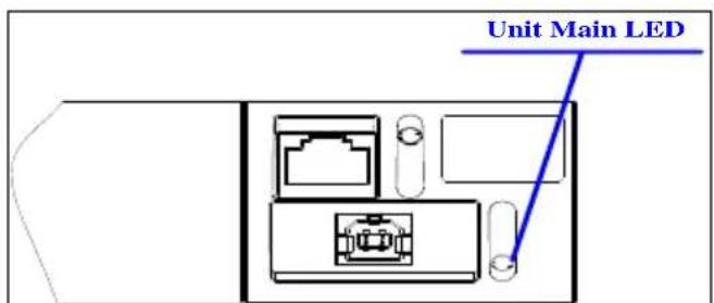
Midspan provides another power fail indication via Midspan's Power Indicator LED; whenever unit's internal power supply fails, Power Indicator LED blinks once every second (Green LED).
text_image
Unit Main LEDFigure 8-4: PD-96xxG Front Panel LED Indication
The information contained in the document is PROPRIETARY AND CONFIDENTIAL information of Microsemi and cannot be copied, published, uploaded, posted, transmitted, distributed or disclosed or used without the express duly signed written consent of Microsemi. If the recipient of this document has entered into a disclosure agreement with Microsemi, then the terms of such Agreement will also apply. This document and the information contained herein may not be modified, by any person other than authorized personnel of Microsemi. No license under any patent, copyright, trade secret or other intellectual property right is granted to or conferred upon you by disclosure or delivery of the information, either expressly, by implication, inducement, estoppels or otherwise. Any license under such intellectual property rights must be approved by Microsemi in writing signed by an officer of Microsemi.
Microsemi reserves the right to change the configuration, functionality and performance of its products at anytime without any notice. This product has been subject to limited testing and should not be used in conjunction with life-support or other mission-critical equipment or applications. Microsemi assumes no liability whatsoever, and Microsemi disclaims any express or implied warranty, relating to sale and/or use of Microsemi products including liability or warranties relating to fitness for a particular purpose, merchantability, or infringement of any patent, copyright or other intellectual property right. The product is subject to other terms and conditions which can be located on the web at hp://www.microsemi.com/company/terms-and-condions
Revision History
| Revision Level / Date | Para. Affected | Description |
| B00/ 23-Jul-14 | Replace PowerDsine by Microsemi | |
| B01/ 25-May-16 | Change Microsemi’s web site, address |
Visit our web site at
www.microsemi.com/products/poe-systems/poe-systems
For technical support, call: +972-9-775-5123
In the USA: 1-877-480-2323
Email: PoEsupport@microsemi.com
Catalog Number: PD-96xx_UG