MS657031X - Network card / adapter Microsens - Free user manual and instructions
Find the device manual for free MS657031X Microsens in PDF.


User questions about MS657031X Microsens
0 question about this device. Answer the ones you know or ask your own.
Ask a new question about this device
Download the instructions for your Network card / adapter in PDF format for free! Find your manual MS657031X - Microsens and take your electronic device back in hand. On this page are published all the documents necessary for the use of your device. MS657031X by Microsens.
USER MANUAL MS657031X Microsens
Industrial IEEE 802.3at
Gigabit PoE Injector
User Manual
FCC Warning
This Equipment has been tested and found to comply with the limits for a Class A digital device, pursuant to Part 15 of the FCC rules. These limits are designed to provide reasonable protection against harmful interference in a residential installation. This equipment generates, uses, and can radiate radio frequency energy. It may cause harmful interference to radio communications if the equipment is not installed and used in accordance with the instructions. However, there is no guarantee that interference will not occur in a particular installation. If this equipment does cause harmful interference to radio or television reception, which can be determined by turning the equipment off and on, the user is encouraged to try to correct the interference by one or more of the following measures:
■ Reorient or relocate the receiving antenna.
■ Increase the separation between the equipment and receiver.
■ Connect the equipment into an outlet on a circuit different from that to which the receiver is connected.
■ Consult the dealer or an experienced radio/TV technician for help.
CE Mark Warning
This is a class A product. In a domestic environment this product may cause radio interference in which case the user may be required to take adequate measures.
Content
FCC Warning......i
CE Mark Warning ...... i
Overview....1
Introduction 1
Features 2
Specifications....3
Packing List....5
Hardware Description......6
Dimensions 6
Front Panel....7
Top View 8
Grounding the PoE Injector....9
Wiring the Power Inputs 10
RJ-45 Pin Assignments.... 11
Installation 14
DIN-Rail Mounting.... 14
Wall-Mount Plate Mounting 16
Troubleshooting....17
Overview
Introduction
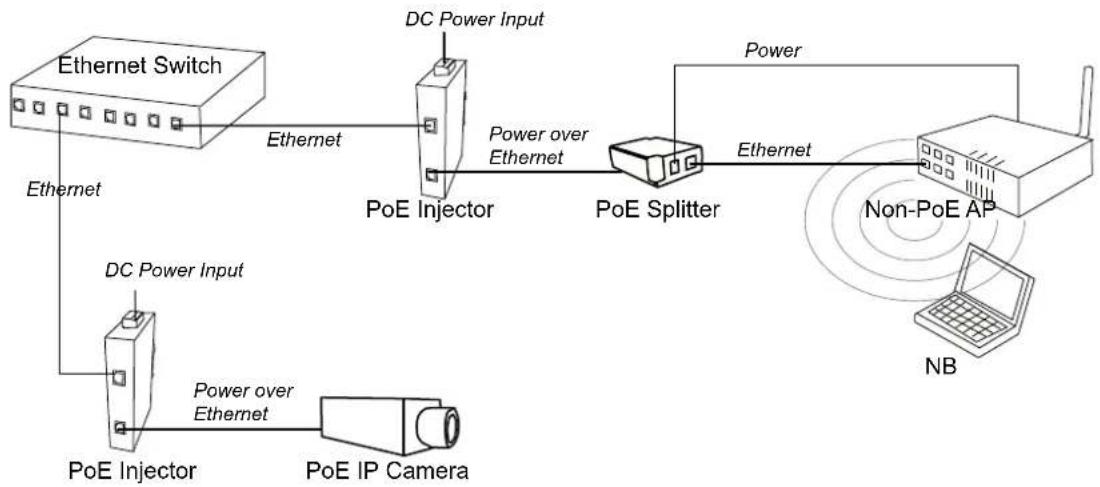
The Industrial Power over Ethernet Injector provides data and DC power through the Ethernet cable to PoE-equipped devices, such as IP camera, access point, PoE splitter or other equipment supporting IEEE 802.3at. The injector is typically installed near the Ethernet switch. The figure below presents the example for the Power over Ethernet Injector application.
flowchart
graph LR
    A["Ethernet Switch"] -->|Ethernet| B["PoE Injector"]
    B -->|Power over Ethernet| C["PoE Splitter"]
    C -->|Power| D["Non-PoE AP"]
    D -->|Power| E["NB"]
    F["PoE Injector"] -->|DC Power Input| B
    G["PoE IP Camera"] -->|Power over Ethernet| B
    H["DC Power Input"] --> B
    I["Power"] --> B
Features
■ 10/100/1000BaseT Power over Ethernet Injector
■ IEEE802.3at compliant
■ Provides power feeding up to 30 watts
■ Overload current protection
■ DC power input ranging from 24 \~ 48V
■ Wide operating temperature -40 \~ 75 °C
Specifications
| Standard | IEEE802.3 10BASE-TIEEE802.3u 100BASE-TXIEEE802.3ab 1000Base-TIEEE802.3af/at Power over Ethernet |
| Connector | LAN port: Data/Signal pins 1, 2, 3, 6PoE port:: Data/Signal pins 1, 2, 3, 6Power pins [1, 2 (V+)], [3, 6 (V-)] |
| Network Cable | 10BASE-T: 2-pair UTP/STP Cat.3, 4,5 cableEIA/TIA-568 100-ohm (100m)100BASE-TX: 2-pair UTP/STP Cat.5 cable (Cat. 5e recommended)EIA/TIA-568 100-ohm (100m)1000Base-T: 4-pair UTP/STP Cat. 5e or above cableEIA/TIA-568 100-ohm (100m) |
| LED | Power x 2PoE x 1 |
| Power Input | DC Input Voltage Range: 24 ~ 48 V_DC |
| Power Input Current | Max. 1.3A@24 V_DC (up to 30 watts supported for PoE) |
| Operating Temperature | -40°C ~ 75°C (-40°F ~ 167°F) |
| Storage Temperature | -40°C ~ 85°C (-40°F ~ 185°F) |
| Operating/Storage Humidity | 5% ~ 95% Humidity (non-condensing) |
| Dimensions | 30mm x 140mm x 95mm (W x H x D) |
| EMC | ■ CE, FCC Class A■ EN61000-6-4■ EN61000-6-2■ EN61000-4-2 (ESD)■ EN61000-4-3 (RS)■ EN61000-4-4 (EFT)■ EN61000-4-5 (Surge)■ EN61000-4-6 (CS)■ EN61000-4-8 (Magnetic Field) |
| Safety | UL508 (pending) |
Packing List
■ 1 x Power over Ethernet Injector
■ 1 x Wall-mounting kit
■ 1 x User Manual (CD-ROM)
Hardware Description
Dimensions
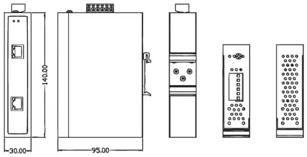
The Power over Ethernet Injector dimensions are 30 mm (W) x 140 mm (H) x 95 mm (D)
Front Panel
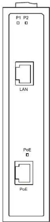
On the front panel the Power over Ethernet Injector is equipped with two RJ-45 ports and three LED indicators.
■ LAN port: It is an ordinary RJ-45 Ethernet port for data transmitting and receiving.
■ PoE port: It is an RJ-45 Ethernet port capable of supplying power over the Ethernet cable as well as forwarding data to powered devices.
text_image
P1 P2 LAN PoE PoE■ P1 & P2: The indicators light up when their respective power inputs are active.
■ PoE: This LED indicator lights up while power feeding works normally.
Top View
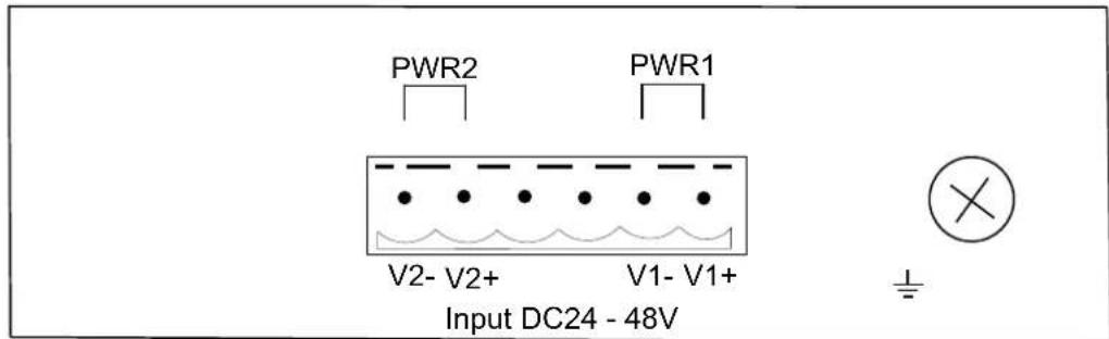
Designed with two power inputs, the PoE Injector allows users to supply redundant power rating in the range of 24 to 48V.
text_image
PWR2 PWR1 V2- V2+ V1- V1+ Input DC24 - 48V ±Power Inputs
Grounding the PoE Injector
Follow the instructions below to attach the PoE Injector to ground.
ATTENTION

When installing the PoE Injector, the ground connection must always be made first and disconnected last.
- On the top of the device, locate and remove the dome screw which has a ground symbol beside it.
- Attach the ground wire to the screw hole with the dome screw.
Wiring the Power Inputs
Please follow the steps below to wire power lines from the terminal block to the compliant external DC power source.
- Before wiring, make sure the power source is disconnected.
- Using the wire-stripping tool, strip a short piece of insulation from the output wires of the DC power source.
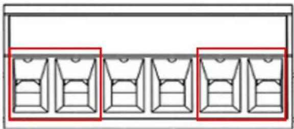
- Identify the positive and negative feed positions for the terminal block connection. See the symbols printed on the panel indicating the polarities and DC input power range in voltage.
natural_image
Pure diagram of three identical rectangular compartments with red bounding boxes, no text or symbols presentPlugs for Power 1 & Power 2
-
Insert the exposed wires into the terminal block plugs. Only wires with insulation should extend from the terminal block plugs. Note that the polarities between the wires and the terminal block plugs must be positive to positive and negative to negative.
-
Use a slotted screwdriver to tighten the captive screws.
ATTENTION

Use Copper Conductors Only, 60/75°C, tightening to 5 lb-in
The wire gauge for the terminal block should be in the range between 12\~24 AWG.
RJ-45 Pin Assignments
The UTP/STP ports will automatically sense for Fast Ethernet
(10Base-T/100Base-TX) or Gigabit Ethernet
(10Base-T/100Base-TX/1000Base-T) connection. Auto MDI/MDIX means that the port can connect to another switch or workstation without changing straight through or crossover cabling. See the figures below for straight through and crossover cable schema.
■ 10/100Base-TX Pinouts
| Pin Number Assignment | |
| 1 | Tx+ |
| 2 | Tx- |
| 3 | Rx+ |
| 6 | Rx- |
Note “+” and “-” signs represent the polarity of the wires that make up each wire pair.
The table below shows the 10Base-T/100Base-TX MDI and MDI-X port pinouts.
| Pin Number | MDI-X Signal Name | MDI Signal Name |
| 1 | Receive Data plus (RD+) | Transmit Data plus (TD+) |
| 2 | Receive Data minus (RD-) | Transmit Data minus (TD-) |
| 3 | Transmit Data plus (TD+) | Receive Data plus (RD+) |
| 6 | Transmit Data minus (TD-) | Receive Data minus (RD-) |
■ 10/100Base-TX Cable Schema
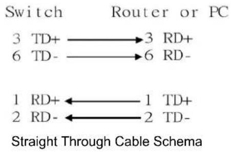
flowchart
graph LR
    A["Switch"] --> B["Router or PC"]
    C["3 TD+"] --> D["3 RD+"]
    E["6 TD-"] --> F["6 RD-"]
    G["1 RD+"] <--> H["1 TD+"]
    I["2 RD-"] <--_J["2 TD-"]
    style G stroke:#000,stroke-width:2px
    style I stroke:#000,stroke-width:2px
    note bottom of G Straight Through Cable Schema
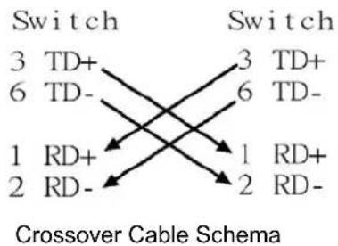
flowchart
graph LR
    A["Switch 3 TD+"] --> B["Switch 3 TD+"]
    A --> C["Switch 6 TD-"]
    D["Switch 1 RD+"] --> E["Switch 1 RD+"]
    D --> F["Switch 2 RD-"]
    G["Crossover Cable Schema"] --> A
    G --> D
    G --> E
    G --> F
■ 10/100/1000Base-T Pinouts
The table below describes the gigabit Ethernet RJ-45 pinouts.
| Pin | Signal name | Description |
| 1 | BI_DA+ | Bi-directional pair A+ |
| 2 | BI_DA- | Bi-directional pair A- |
| 3 | BI_DB+ | Bi-directional pair B+ |
| 4 | BI_DC+ | Bi-directional pair C+ |
| 5 | BI_DC- | Bi-directional pair C- |
| 6 | BI_DB- | Bi-directional pair B- |
| 7 | BI_DD+ | Bi-directional pair D+ |
| 8 | BI_DD- | Bi-directional pair D- |
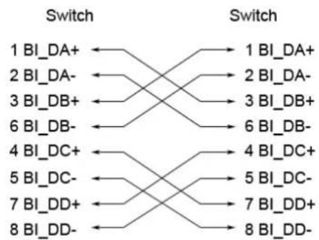
■ 10/100/1000Base-T Cable Schema
The following two figures illustrate the 10/100/1000Base-T cable schema.
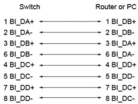
flowchart
graph LR
    A["1 BI_DA+"] --> B["1 BI_DB+"]
    C["2 BI_DA-"] --> D["2 BI_DB-"]
    E["3 BI_DB+"] --> F["3 BI_DA+"]
    G["6 BI_DB-"] --> H["6 BI_DA-"]
    I["4 BI_DC+"] --> J["4 BI_DD+"]
    K["5 BI_DC-"] --> L["5 BI_DD-"]
    M["7 BI_DD+"] --> N["7 BI_DC+"]
    O["8 BI_DD-"] --> P["8 BI_DC-"]
Straight Through Cable Schema
flowchart
graph LR
    A["1 BI_DA+"] --> B["1 BI_DA+"]
    A --> C["2 BI_DA-"]
    A --> D["3 BI_DB+"]
    A --> E["6 BI_DB-"]
    A --> F["4 BI_DC+"]
    A --> G["5 BI_DC-"]
    A --> H["7 BI_DD+"]
    A --> I["8 BI_DD-"]
    B --> J["1 BI_DA+"]
    C --> K["2 BI_DA-"]
    D --> L["3 BI_DB+"]
    E --> M["6 BI_DB-"]
    F --> N["4 BI_DC+"]
    G --> O["5 BI_DC-"]
    H --> P["7 BI_DD+"]
    I --> Q["8 BI_DD-"]
Crossover Cable Schema
DIN-Rail Mounting
Assembling the DIN-Rail Clip
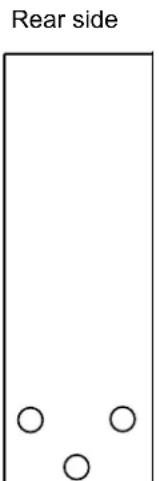
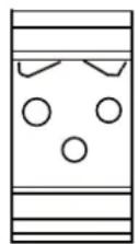
The DIN-rail clip is screwed on the device in the factory. If not, please refer to the following steps and figure to secure the DIN-rail clip on the device.
- Use the screws to secure the DIN-rail clip at the rear of the device.
- To remove the DIN-rail clip, reverse step 1.
text_image
Rear sideDIN-rail clip
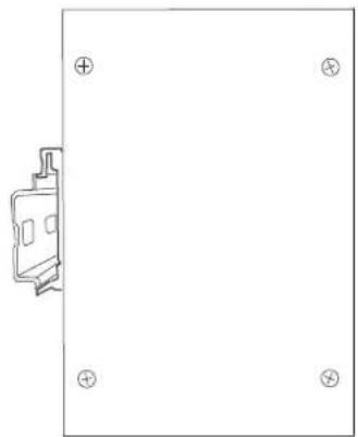
Hanging the PoE Injector
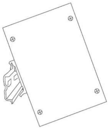
Follow the steps below to hang the device on the standard DIN rail.
- First, position the rear side of the unit directly in front of the DIN rail. Make sure the top of the clip hooks over the top of the DIN rail.
natural_image
Simple line drawing of a rectangular plate with four circular holes and a small bracket on the left (no text or symbols)- Push the unit downward.
natural_image
Simple line drawing of a mechanical component with four circular holes, no text or symbols present- Check the DIN-Rail clip is tightly fixed on the DIN rail.
- To remove the device from the track, reverse the steps above.
Wall-Mount Plate Mounting
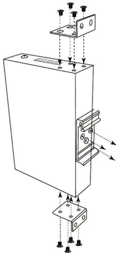
Follow the steps below to mount the device with the wall-mount plates.
-
To remove the DIN-Rail clip from the device, unscrew the screws that secure it.
-
Align the screw holes of the wall-mount plates with the ones of the device.
-
Use the screws included to secure the wall-mount plates on the device.
-
Use the hook holes of the wall-mount plates to hang the device on the wall.
-
To remove the wall-mount plates, reverse the steps above.
natural_image
Technical line drawing of a mechanical assembly with mounting holes and internal components (no text or symbols)Troubleshooting
- Verify that you are using the right power cord/adapter. Please don't use a power adapter with DC outputs higher than the power rating of this equipment, or it will be damaged.
■ Select the proper UTP/STP cable for your network. Please check that you are using the right cable. Use unshielded twisted-pair (UTP) or shielded twisted-pair (STP) cable for the RJ-45 connections: 100Ω Category 3, 4, or 5 cable for 10Mbps connections or 100Ω Category 5 cable for 100Mbps connections. Also be sure that the length of any twisted-pair connection does not exceed 100 meters (328 feet).
■ Diagnosing LED Indicators: The device can be easily monitored through LED indicators, which describe common problems the user may encounter and where the user can find possible solutions.
If the power indicator does not light up when the power cord is plugged in, you may have a problem with power cord. Then check for loose power connections, power losses or surges at the power outlet. If you still cannot resolve the problem, contact your local dealer for assistance.
If the cables are properly connected and the LED indicators show normal, but the packets still cannot transmit, please check your system's Ethernet devices' configuration or status.