Z-3250 - Barcode Reader Zebex - Free user manual and instructions
Find the device manual for free Z-3250 Zebex in PDF.


| Brand | Zebex |
| Model | Z-3250 |
| Product Type | Handheld Wireless Barcode Scanner |
| Microprocessor | 32-bit CPU |
| Scan Engine | 650nm visible laser diode, Class 1 laser product |
| Wireless Range | Up to 100 meters (75 meters with dongle) |
| Wireless Frequency | 2.4 GHz |
| Wireless Modes | Dongle Host, SPP Master/Slave, HID |
| Wired Connection | Micro USB to USB (USB Online mode) |
| Power Source | Rechargeable battery (manufacturer provided) |
| Charging | Via micro USB cable (host or 5V adapter) |
| Scan Modes | Handheld, Presentation, Auto-scan, Alternate, Trigger |
| Barcode Symbologies | UPC/EAN, Code 39, Code 128, Codabar, ITF, MSI, etc. |
| Data Capacity (Batch Mode) | 61,365 bytes |
| Indicators | LED (blue, green, red) and audible beeper |
| Operating Temperature (Charging) | 0°C to 35°C (32°F to 95°F) |
| Laser Safety | Class 1, <3.9 µW radiant power |
| Radio Compliance | EN55022, FCC Part 15 Class A, CE |
| Battery Caution | Do not short, peel, or use incorrect type; risk of explosion |
| Accessories Included | Battery, dongle (optional), micro USB cable, 5V adapter, quick guide |
Frequently Asked Questions - Z-3250 Zebex
User questions about Z-3250 Zebex
0 question about this device. Answer the ones you know or ask your own.
Ask a new question about this device
Download the instructions for your Barcode Reader in PDF format for free! Find your manual Z-3250 - Zebex and take your electronic device back in hand. On this page are published all the documents necessary for the use of your device. Z-3250 by Zebex.
USER MANUAL Z-3250 Zebex
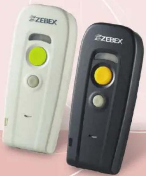
Handy Wireless Scanner
natural_image
Two ZEBEX remote devices, one white and one black, each with a yellow circular button and control buttons (no visible text or symbols)Revision History
Changes to the original manual are listed below:
| Version Date | Description of Version | |
| 1.0 | 2014/01/22 | Initial release |
| 1.1 2014/04/21 | Added Windows | connection instructions |
| 1.2 2014/07/09 | Added SSP mode | setups |
| 1.3 2015/2/3 | Corrected Confirm setting wordings | |
Important Notice
No warranty of any kind is made in regard to this material, including, but not limited to, implied warranties of merchantability or fitness for any particular purpose. We are not liable for any errors contained herein nor for incidental or consequential damages in connection with furnishing, performance or use of this material. We shall be under no liability in respect of any defect arising from fair wear and tear, willful damage, negligence, abnormal working conditions, failure to follow the instructions and warnings, or misuse or alteration or repair of the products without written approval. No part of this document may be reproduced, transmitted, stored in a retrieval system, transcribed, or translated into any human or computer or other language in any form or by any means electronic, mechanical, magnetic, optical, chemical, biological, manual or otherwise, except for brief passages which may be quoted for purposes of scholastic or literary review, without express written consent and authorization. We reserve the right to make changes in product design without reservation and without notification. The material in this guide is for information only and is subject to change without notice. All trademarks mentioned herein, registered or otherwise, are the properties of their various, ill, assorted owners.
General Handling Precautions
Do not dispose the scanner in fire.
Do not put the scanner directly in the sun or by any heat source.
Do not use or store the scanner in a very humid place.
Do not drop the scanner or allow it to collide violently with other objects.
Do not take the scanner apart without authorization
Guidance for Printing
This manual is in A5 size. Please double check your printer setting before printing it out. When the barcodes are to be printed out for programming, the use of a high-resolution laser printer is strongly suggested for the best scan result.
Copyright © 2015. All rights reserved.
Radio Notice
This equipment generates uses and can radiate radio frequency energy. If not installed and used in accordance with the instructions in this manual, it may cause interference to radio communications. The equipment has been tested and found to comply with the limits for a Class A computing device pursuant to EN55022 and 47 CFR, Part 2 and Part 15 of the FCC rules. These specifications are designed to provide reasonable protection against interference when operated in a commercial environment.
Radio and Television Interference
Operation of this equipment in a residential area can cause interference to radio or television reception. This can be determined by turning the equipment off and on. The user is encouraged to try to correct the interference by one or more of the following measures:
- Reorient the receiving antenna.
- Relocate the device with respect to the receiver.
- Move the device away from the receiver.
- Plug the device into a different outlet so that the device and the receiver are on different branch circuits.
If necessary the user may consult the manufacturer, and authorized dealer, or experienced radio/television technician for additional suggestions. The user may find the following booklet prepared by the Federal Communications Commission helpful: "How to Identify and Resolve Radio-TV Interference Problems." This booklet is available from the U.S. Government Printing Office, Washington, DC 20402 U.S.A., Stock No. 04000003454. 0
Laser Safety
This equipment generates, uses, and can radiate radio frequency energy. If not installed and used in accordance with the instructions in this manual, it may cause interference to radio communications. The equipment has been tested and found to comply with the limits for a Class A computing device pursuant to EN55022 and 47 CFR, Part 2 and Part 15 of FCC Rules. These specifications are designed to provide reasonable protection against interference when operated in a commercial environment.
Radiant Energy: The laser scanner uses one low-power visible laser diodes operating at 650nm in an opto-mechanical scanner resulting in less than 3.9 W radiated power as observed through a 7mm aperture and averaged over 10 seconds.
Do not attempt to remove the protective housing of the scanner, as unscanned laser light with a peak output up to 0.8mW would be accessible inside.
Laser Light Viewing: The scan window is the only aperture through which laser light may be observed from this product. A failure of the scanner engine, while the laser diode continues to emit a laser beam, may cause emission levels to exceed those for safe operation. The scanner has safeguards to prevent this occurrence. If, however, a stationary laser beam is emitted, the failing scanner should be disconnected from its power source immediately.
Adjustments: Do not attempt any adjustments or alteration of this product. Do not remove the protective housing of the scanner. There are no user-serviceable parts inside.
Optical: The use of optical instruments with this product will increase the eye hazard. Optical instruments include binoculars, magnifying glasses, and microscopes but do not include normal eye glasses worn by the user.
CAUTION: Use of controls or adjustments or performance of procedures other than those specified herein may result in hazardous radiation exposure.
For CE-Countries
This scanner is in conformity with CE standards. Please note that an approved, CE-marked power supply unit should be used in order to maintain CE conformance.
Power Supply
- Use only the type of battery and the charging equipments that came with your scanner.
- Using any other type of battery and charging equipment may damage the scanner and invalidate the warranty.
- Do not short the battery terminals. The battery could overheat.
- Do not attempt to split or peel the outer casing.
- Remove the battery if the scanner is not going to be used for a long time. If the battery is left unused for more than 3 months, you need to charge the battery before use.
Caution
RISK OF EXPLOSION IF BATTERY IS REPLACED BY AN INCORRECT TYPE DISPOSE OF USED BATTERIES ACCORDING TO THE INSTRUCTIONS
Wireless Communication
● Wireless technology operates 100M / 75M with communication dongle. Maximum communication range may vary depending on obstacles (person, metal, wall, etc.) or electromagnetic environment.
● The following conditions may affect the sensitivity of wireless communication.
There is an obstacle such as a person, metal, or wall between this unit and wireless device.
A device using 2.4 GHz frequency, such as a wireless LAN device, cordless telephone, or microwave oven, is in use near this unit.
● Because wireless devices and wireless LAN (IEEE802.11b/g) use the same frequency, microwave interference may occur and resulting in communication speed deterioration, noise, or invalid connection if this unit is used near a wireless LAN device. In such a case, perform the following.
■ Use this unit at least 10 m (about 30 ft) away from the wireless LAN device.
If this unit is used within 10 m (about 30 ft) of a wireless LAN device, turn off the wireless LAN device.
■ Install this unit and wireless device as near to each other as possible.
- Microwaves emitting from a wireless device may affect the operation of electronic medical devices. Turn off this unit and other wireless devices in the following locations, as it may cause an accident.
■ Where inflammable gas is present, in a hospital, train, airplane, or a petrol station
■ Near automatic doors or a fire alarm
- This unit supports security capabilities that comply with the wireless standard to provide a secure connection when the wireless technology is used, but security may not be enough depending on the setting. Be careful when communicating using wireless technology.
We do not take any responsibility for the leakage of information during wireless communication.
● Connection with all wireless devices cannot be guaranteed.
A device featuring wireless function is required to conform to the wireless standard specified by wireless SIG, and be authenticated.
Even if the connected device conforms to the above mentioned wireless standard, some devices may not be connected or work correctly, depending on the features or specifications of the device.
● Depending on the device to be connected, it may require some time to start communication.
Tips to help improve your wireless network
- Position the access point (host/dongle) in a relatively empty space at central location.
When possible, place the access point in a central location on the high ground (1m or above). If your access point is against an outside wall, the signal will be weak on the other side of the room.
X
Bad host placement
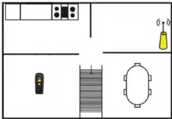
natural_image
Top-down layout diagram of a room with furniture, a wall-mounted device, and a coffee cone emitting signal waves (no text or labels)0
Good host placement
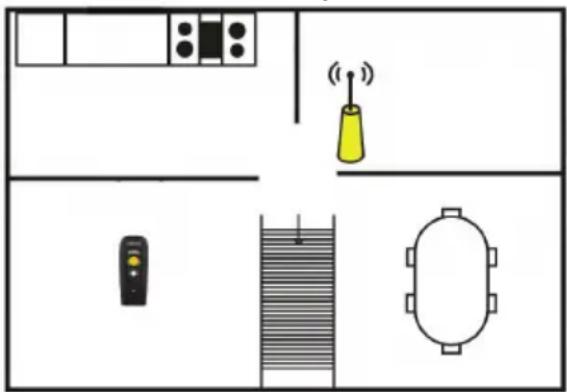
text_image
Floor plan diagram with labeled furniture and room features including a yellow bell, wall-mounted device, and oval tablewareX
Bad host placement
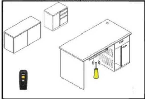
natural_image
Isometric line drawing of a kitchen appliance setup including a cabinet, front desk, and remote control (no text or symbols)0
Good host placement
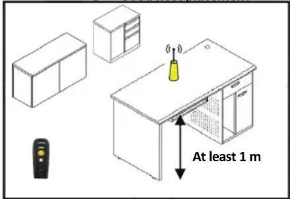
text_image
At least 1 m-
Move the access point (host/dongle) off the floor and away from walls and metal objects (such as metal file cabinets). Metal objects, walls, and floors will interfere with your wireless signals. The closer your access point is to these obstructions, the more severe the interference, and the weaker your connection will be.
-
Reduce wireless interference.
The most common wireless technology, 802.11g (wireless-G), operates at a frequency of 2.4 gigahertz (GHz). Many cordless phones, microwave ovens, hospital equipments, refrigerator, LED, and other wireless electronics also use this frequency. If you use these wireless devices in your office, your device might not be able to "hear" the signals over the noise coming from them.
If your network uses wireless-G, you can quiet the noise by avoiding wireless electronics that use the 2.4 GHz frequency. Instead, look for cordless phones and other devices that use the 5.8 GHz or 900 megahertz (MHz) frequencies. Because 802.11n (wireless-N) operates at both 2.4 GHz and the less frequently used 5.0 GHz frequency, you may experience less interference on your network if you use this technology.
Avoid possible wireless interference
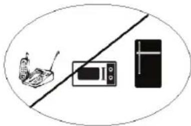
natural_image
Simple line drawing of a mobile phone, microwave, and refrigerator with no text or symbols- Update the firmware or driver of your wireless dongle.
If you are using a wireless dongle or other similar devices to make the connection, getting the latest firmware or driver updates may improve the performance. Visit your manufacturer's website for the updates.
Table of Contents
Important Notice....ii
General Handling Precautions....ii
Guidance for Printing ......ii
Laser Safety ....iii
For CE-Countries......iv
Power Supply iv
Caution......iv
Wireless Communication....v
Introduction....1
Scanner and Accessories....2
Charging the Battery 4
Power on the Scanner 5
Function Button 5
How to Scan....6
Radio Communication Host Type....7
Dongle Host Mode 7
SPP Master/SPP Slave Mode ....7
HID Mode....7
Scanner USB online to Host 8
USB Online Mode....8
Visible Indicators....8
Scanner LED....8
Dongle LED 9
Sound Indicators 9
ACK/NAK Protocol or Frame Packing....10
Scanner to Remote Application....11
Barcode Type Table ....12
Firmware Update ....12
Programming Guide ....13
Connecting to a Host....17
USB Online Mode....17
Disable USB communication ....17
Enable USB communication....17
Set USB as the primary connection....17
Dongle Host Mode ....18
Dongle Host Pairing....18
Wireless Mode....19
SPP Slave Mode....19
Connect to PC [Window]....20
SPP Master Mode....24
HID mode 28
Setting Pin Code 29
Deleting pin code 29
Reset Name 29
Setting Name....30
Wireless Discovery 30
Secure Simple Pairing....31
Data Transmit Method 32
Normal 32
Out of Range 32
Batch Mode....33
Clearing Batch 33
Batch Transfer....34
Batch Mode Sounds Settings....34
System Function Settings 35
Scan Mode 36
Radio Communication Setting....37
Dongle Host mode....37
USB Online mode 37
HID mode 38
SPP Master/Slave mode 38
Device Setting....38
Data Transmit Mode....40
Radio protocol communication parameter 41
Power off timeout parameter ....42
Same Code Delay....43
Operation Function Setting....45
Good Read Beeper Tone Selection 45
Beeper duration Selection....46
Inter Character Delay ....47
Inter Message Delay....47
Interface Settings 48
RS-232C Interface Setting....48
USB Interface Setting....49
Smart Phone Software Keypad Control Setting....51
The Symbologies ....52
Codabar Parameter Setting....52
Code 39 Parameter Setting ....54
Code 93 Parameter Setting ....56
Code 128 Parameter Setting ....57
Chinese Post Code Parameter Setting 58
MSI/Plessy Parameter Setting 59
Code 11 Interface Setting....60
ITF 2 of 5 Parameter Setting....61
Standard 2 of 5 Parameter Setting....63
Industrial 2 of 5 Parameter Setting 64
UPC/EAN/JAN Parameter Setting 65
Telepen Parameter Setting....70
Matrix 2 of 5 Parameter Setting....71
Data Editing....75
Identifier Code 75
Header and Trailer....77
Full ASCII Code 39 Table ....78
Appendix 1: USB Virtual COM Driver Installation ....83
Appendix 2: Barcode Length Setting....84
Introduction
Designed for optimal reading performance, the compact handy wireless scanner offers wide scanning range and wireless communication technology for easy handling of any applications.
The scanner includes a 32-bit CPU and excellent scan engine in a small yet powerful unit delivering intuitive and rapid scanning regardless of environment.
Key Features:
- Compact, light weight, and portable
● Compatible with iOS devices such as iPad/iPhone
● 32-bit microprocessor

text_image
Micro USB slot Back Cover Lock LED Indicator Power Button/ Scan Trigger Function Button/ Off Button Hand Strap Hole Battery Compartment Scan WindowScanner and Accessories
The scanner package contains:
Wireless scanner with battery
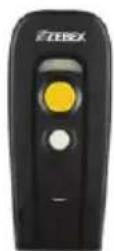
Dongle (optional)
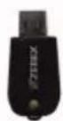
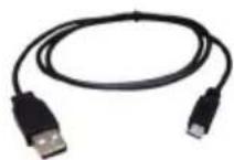
Micro USB to USB cable
5V USB Power adapter
Quick Guide
Quick Guide

*If any contents are damaged or missing, please contact your dealer immediately.
*Actual product/accessories appearance may vary.
Battery Installation
Installing Batteries
Please follow the steps below to install the batteries.

Always use the rechargeable batteries provided by the manufacturer to avoid any non-compatible danger or void the warranty.
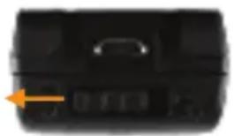
- Move the lock for the battery compartment to the unlock position and remove the back cover.
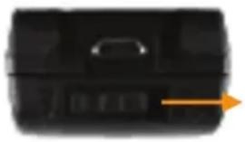
natural_image
Black rectangular object with a small protrusion and an orange arrow pointing right (no visible text or symbols)- Align the metal contact on the battery with the metal contact inside the battery compartment and insert the battery.
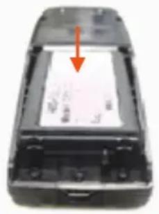
natural_image
Interior view of a black electronic device with a red arrow pointing to a screen (no visible text or symbols)- Place the back cover back on the scanner and move the lock to the lock position.
natural_image
Black briefcase with orange arrow pointing to a button (no visible text or symbols)Charging the Battery
To charge the battery using the USB cable:
There are two methods to charge scanner via USB cable.
-
Host USB Power
● Power adaptor -
Connect the micro USB connector directly to the scanner.
- Connect the other end of the USB connector to the host to begin charging. You can also connect the USB cable to an outlet using the power adapter to charge the battery.
- The battery begins charging when the scanner LED indicator starts flashing green. LED turns steady green when charging is complete.

● The scanner will power on automatically when charging.
● Batteries shipped may not be full charged and should be fully charged for maximum charge capacity.
- Recommended charging environment is temperature in 0°C\~35°C (32°F\~95°F).
Power on the Scanner
- Ensure the battery is fully charged. Please refer to the previous section to charge the battery.
- Press and hold the power button for 1 second until a long beep sound is heard to turn on the scanner.
- To power off the scanner press and hold the function / off button for 3 second until 2 short beeps are heard.
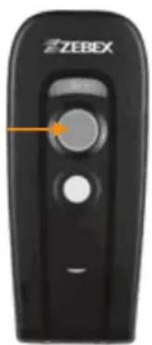
text_image
ZEBEXPower on
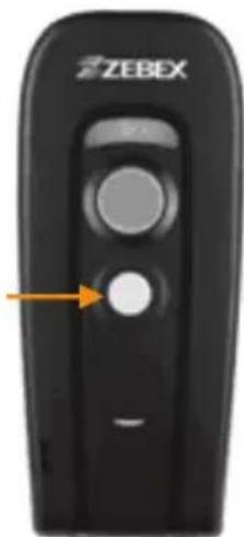
text_image
ZEBEXPower off
Function Button
The function button can be used as the power off key or to call or hide virtual keyboard when the scanner is connected with iPad, iPhone or other devices (not including Android devices).
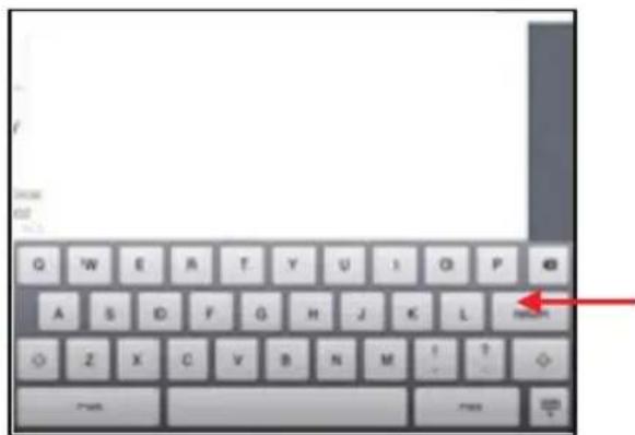
text_image
G W E A T Y U I O P A S D F G H J K L H Z X C Y B N M I T 700 700Press function button to call or hide the keyboard
How to Scan
There are two ways to scan with this device.
● Handheld scanning
● Presentation scanning
Handheld scanning
- Power on the scanner.
- Press the scan trigger and aim at the barcode.
- When decoding is successful, the scanner beeps and the LED indicates blue.
Presentation Scanning
- Set the scanner for presentation scanning mode.
- Move the barcode label approach the scanner scanning zone.
- When decoding is successful, the scanner beeps and the LED indicates blue.
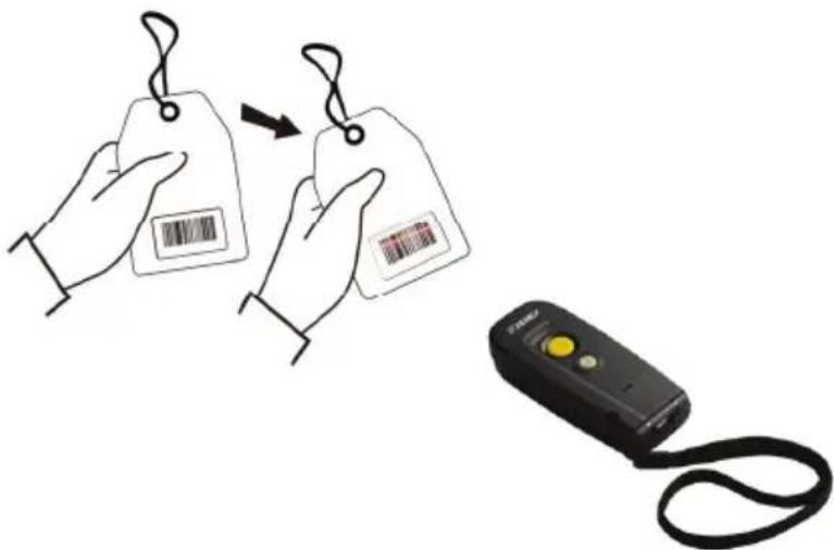
text_image
Diagram showing two handbags with barcode and a handheld device connected to a label, illustrating a scanning or linking operation.Radio Communication Host Type
This scanner support three radio communication types:
- Dongle mode
● SPP master/slave mode - HID mode
Dongle Host Mode
The scanner communicates with the host through the dongle. One dongle can be used to connect multiple scanners (factory designed dongle only).
Typically, scanner and dongle in the same delivery box are paired in factory. As soon as both are powered on, they should find and connect to each other immediately.
However, under special circumstance that the scanner and the dongle are not paired with the dongle, please follow instructions in later chapters to pair the dongle.
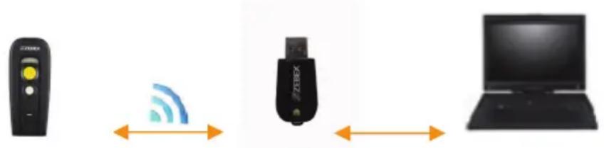
text_image
Diagram showing wireless signal transmission between a remote device, a USB flash drive, and a laptop.SPP Master/SPP Slave Mode
The scanner can communicate with the host through wireless connection. Please see Wireless Mode for detail operation information.
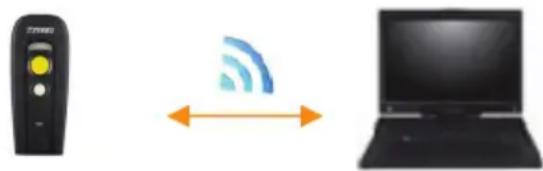
natural_image
Three objects: a remote control unit, a wireless signal icon, and a laptop (no text or symbols)HID Mode
The scanner communicates with the smart phone through HID connection. Please see HID mode for detail operation information
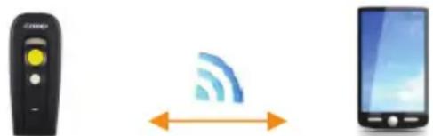
natural_image
Three icons: a remote control, a Wi-Fi symbol with signal waves, and a smartphone (no text or symbols)Scanner USB online to Host
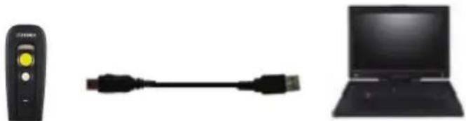
The scanner provides other ways for you to connect to the host. When the radio communication is not available, the scanner can be connected to transmit data via USB Online mode. Please see USB Online Mode for detail operation information.
USB Online Mode
The scanner connects directly to a USB host to recharge and transmit data.
natural_image
Three electronic devices: a remote control unit, a USB cable, and a laptop computer (no visible text or symbols)Visible Indicators
Scanner LED
Please see the following for the operational indication of the scanner.
| LED Status Indication | ||
| Blue flashing | Waiting for radio connection (flash time 0.5s : 0.5s). | |
| Blue fast flashing | Radio connecting. | |
| Blue slow flashing | Device connected (flash time 0.03s : 3s). | |
| Blue flash once A barcode was decoded successfully | ||
| Blue fast flashing Data transmission | ||
| Green flashing Charging mode | ||
| Steady green Battery fully charged | ||
| Steady red | Programming mode | |
| Red flashing slow (with continuous beep sound) | Low battery warning | |
| Red flash twice (with 2 beep sound) | Very low battery warning | |
Dongle LED
Please see the following for the operational indication of the scanner.
| LED Status Indication | ||
| Blue flashing | Dongle is detected by the host,communication not yet established | |
| Steady blue | Dongle is connected to the host | |
| Blue flash | once Data transmission | |
| Steady red | Dongle is plugged into the host | but notdetected by the host or dongle is in theupdate mode |
Sound Indicators
When the scanner is in operation, it provides audible feedback. The beeps indicate the status of the scanner.
| Beep Indication | |
| A long beep Power on scanner. | |
| One beep A barcode has been successfully decoded and data is either transfer to the host or saved in the memory. | |
| 1 high - low - high beeps Scan dongle pair barcode. | |
| Four short medium beeps Data communication failed or out of range. | |
| Intermission medium-low beeps | Low battery warning. |
| 1 short medium – low beeps | Scanner is power down. |
| 1 long high – medium beeps | Enter programming mode. |
| 1 long medium - medium beeps | Exit Programming mode. |
ACK/NAK Protocol or Frame Packing
When scanner is in SPP Master/Slave mode, and add in the data protocol or packing could confirm the data reliability. Refer to below for different setting options:
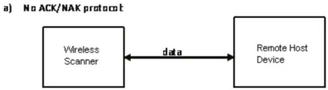
flowchart
graph LR
    A["Wireless Scanner"] <-->|data| B["Remote Host Device"]
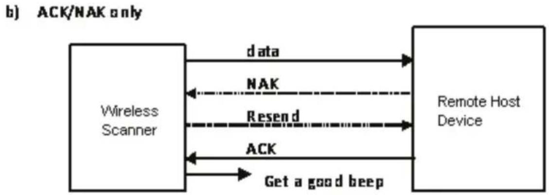
flowchart
graph LR
    A["Wireless Scanner"] -->|data| B["Remote Host Device"]
    B -->|NAK| A
    A -->|Resend| B
    B -->|ACK| A
    A -->|Get a good beep| B
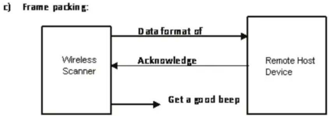
flowchart
graph LR
    A["Wireless Scanner"] -->|Data format of| B["Remote Host Device"]
    B -->|Acknowledge| A
    A -->|Get a good beep| B
Scanner to Remote Application
Data Format of Packet
To send a data (barcode) to the remote application, the scanner has to encapsulate it:
| EAH (Header) | Size of payload | FEH (Format Byte) | Data ID | Data | Barcode Type | AEH (End of Byte) | Reserved Byte |
| 1 byte 1 | byte 1 byte | 1 byte Varies | 1 byte | 1 byte 1 byte |
| Title Definition | |
| Header Character (EAH) The character ID at the head of every data. It has to start with EAH. | |
| Size of Payload The encapsulated data length excluding header character. | |
| Format Byte (FEH) Differentiate data format; barcode data is always FEH. | |
| Data ID The number of each data. If receive the same ID more than once, only the first one is valid, delete the rest. | |
| Barcode Type (1 byte) | Please refer to the Barcode Type Table. |
| Data | Decoded barcode data. |
| End of Byte (AEH) | Record data ends. |
| Reserved Byte | Reserved for future use. |
Example:
If Code39 barcode data is "ABCD", than sender sends out:
$$ \mathrm{EAH} + 0 \mathrm{AH} + \mathrm{FEH} + \mathrm{ID} +" \mathrm{ABCD}" + 1 1 \mathrm{H} + \mathrm{AEH} + \text {Reserved Byte} $$
$$ 0 A H = 1 + 1 + 1 + 4 + 1 + 1 + 1 $$
Acknowledge packet
If scanner sends out:
EAH, 0AH, FEH, 01H, "ABCD", 011H, AEH, EEH
Remote acknowledges: 55H +01H + 55H
Barcode Type Table
| Code Value | |
| Code39 | 0x11 |
| Codabar | 0x01 |
| Code128 | 0x03 |
| Interleaved 2/5 0x02 | |
| Code93 | 0x06 |
| UPC-E | 0x14 |
| UPC-A | 0x24 |
| EAN-8 | 0x34 |
| EAN-13 | 0x44 |
| Chinese Post Code 0x05 | |
| MSI | 0x07 |
Firmware Update
To update the firmware, scan the Start of Configuration barcode then scan Dongle USB Update or Scanner USB Update to enter Firmware Update mode. To exit Firmware Update mode without updating, please remove and re-insert the battery.
Start Of Configuration
Update firmware using dongle (Dongle Host mode only)

Update firmware using USB connection
Programming Guide
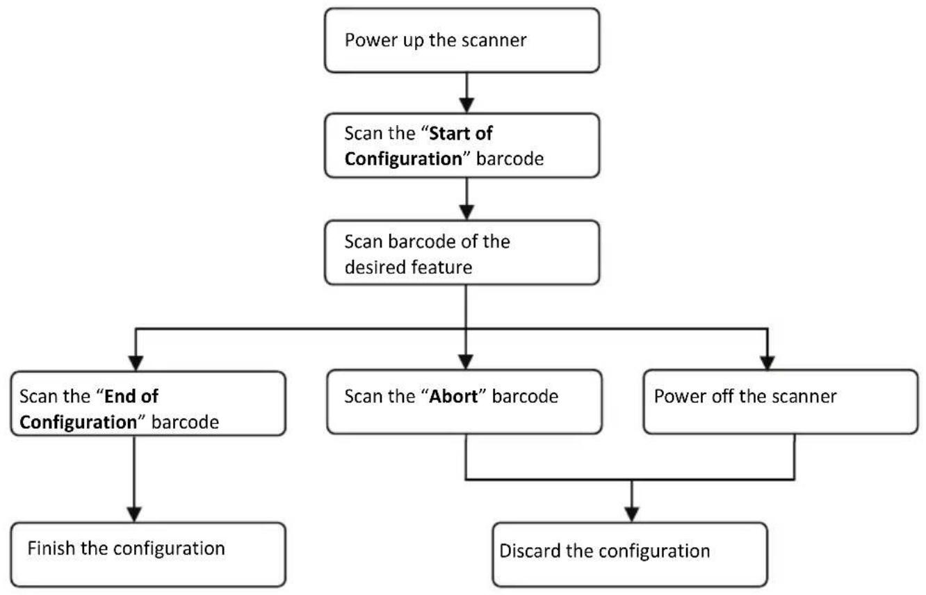
Program Procedure Using Barcode Manual
-
Power up the scanner.
-
Scan the Start of Configuration barcode.
-
Scan the barcode for the desired feature. Multiple features can be enabled/disabled before scanning the End of Configuration barcode.
-
Scan the End of Configuration barcode and save the new configuration. Power off and on the scanner when the setting is done.
-
To give up a configuration change, power off the scanner before scanning the End of Configuration barcode or scan the Abort barcode.
-
For some parameter setting, such as barcode length and identifier code, it is required to scan the Set barcode to save the configuration.
flowchart
graph TD
    A["Power up the scanner"] --> B["Scan the "Start of Configuration" barcode"]
    B --> C["Scan barcode of the desired feature"]
    C --> D["Scan the "End of Configuration" barcode"]
    C --> E["Scan the "Abort" barcode"]
    C --> F["Power off the scanner"]
    D --> G["Finish the configuration"]
    E --> H["Discard the configuration"]
Default Parameters
The factory default setting table gives the default settings of all the programmable parameters. The default settings will be restored whenever the "Reset" programming label is scanned and the scanner is in programming mode. Default values are highlighted in grey background in the settings.
Factory Default Setting
| Parameter | Default |
| Radio communication | |
| Wireless host Dongle | |
| Pairing mode Unlocked | |
| Data transmit Normal | |
| Radio protocol timeout 5 seconds | |
| Power off timeout 20 minutes | |
| Encryption | Enable |
| Dongle Host | |
| RS-232 communication | |
| Terminator | |
| USB Communication | |
| Terminator Enter | |
| Code mode Scan code | |
| Keyboard | US |
| Pair contact on dongle Enable | |
| Scanner | |
| Decoder Selection Default | |
| EAN/UPC | Enable |
| CODE 39 | Enable |
| Code 32 | Disable |
| CODABAR | Enable |
| ITF 2 OF 5 | Enable |
| MSI | Disable |
| Chinese post code Disable | |
| Code 93 | Enable |
| Code 128 | Enable |
| EAN-128 | Disable |
| Telepen | Disable |
| Code 11 | Disable |
| Standard 2 of 5 Disable | |
| Industrial 2 of 5 Disable | |
| GS1 DataBar Disable | |
| Beeper Sound Default | |
| Frequency | Medium |
| Duration | Medium |
| Operating Parameter Default | |
| Scan mode Trigger mode | |
| Stand mode Enable | |
| Header and trailer None | |
| Inter-message delay None | |
| Inter-character delay None | |
| Code Identifiers Default | |
| Identifier code as ZEBEX standard | Disable |
| Identifier code as AIM standard | Disable |
| Code 39 identifier code M | |
| ITF 2 of 5 identifier code | I |
| Chinese post code identifier code | H |
| UPC-A identifier code | A |
| UPC-E identifier code | E |
| EAN-13 identifier code | F |
| EAN-8 identifier code | FF |
| Codabar identifier code | N |
| Code 128 identifier code | K |
| Code 93 identifier code L | |
| MSI identifier code | P |
| Code 11 identifier code O | |
| Standard 2 of 5 identifier code | S |
| Industrial 2 of 5 identifier code | D |
| GS1 DataBar identifier code | RS |
| GS1 DataBar Limited identifier code | RL |
| GS1 DataBar Expanded identifier code | RX |
Default Data Transmit Format
| Code | Message |
| EAN-13 D1 D2 D3 D4 D5 | D6 D7 D8 D9 D10 D11 D12 D13 |
| EAN-8 D1 D2 D3 D4 D5 D6 | D7 D8 |
| UPCA D1 D2 D3 D4 D5 D6 | D7 D8 D9 D10 D11 D12 |
| UPCE D1 D2 D3 D4 D5 D6 | D7 D8 |
| CODE128 D1-Dx (default 3~62) | |
| EAN128 C1 D1-Dx (default 3~62) | |
| CODE39 D1-Dx (default 3~62) | |
| CODABAR D1-Dx (default 6~32) | |
| INTERLEAVED 2/5 D1-Dx (default 6~32) | |
| CHINESE POST CODE | D1-Dx (default 8~32) |
| CODE93 D1-Dx (default 3~32) | |
| MSI | D1-Dx (default 6~32) |
format
Connecting to a Host
The scanner provides several data transmit methods to communicate with the host. User may select the method according to their preferences. Read this section to learn the setups for connecting to different hosts.
Start Of Configuration
USB Online Mode
The scanner connects directly to a USB host to recharge and transmit data. You may enable or disable the functions using the following settings.
Disable USB communication
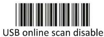
text_image
USB online scan disableDisable USB communication.
Enable USB communication
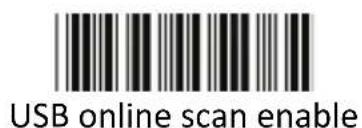
text_image
USB online scan enableWireless connection as the primary communication option to the host. USB connection is only used when wireless is disconnected.
Set USB as the primary connection
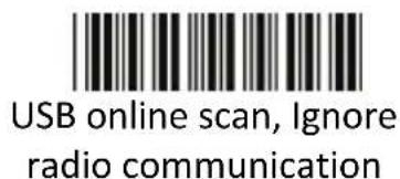
text_image
USB online scan, Ignore radio communicationUSB connection as the primary communication option to the host when it is available. Wireless mode is set as the secondary option.
End Of Configuration
Dongle Host Mode
The scanner communicates with the host through the dongle. Typically, scanner and dongle in the same delivery box are paired and corresponded to host interface in factory. To check if the scanner is paired to the dongle, check the scanner LED for slow blue flash and check the top dongle LED for steady blue light. If scanner LED and dongle LED are both flashing blue, follow the steps below to radio connect the scanner and dongle.
Dongle Host Pairing
- Please make sure the scanner LED is flashing blue indicating it's not linked to any host. If the LED shows steady blue, the scanner is already paired to another scanner so you must unpair the scanner before continuing.
- Power on the scanner and enable dongle host mode if necessary.
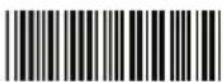
Enable dongle mode with this setting
Dongle Host mode enable
- Use the scanner to scan the pairing barcode at the bottom of the dongle to begin pairing. 3 short beeps will be heard.
- The LED indicator on the scanner will flash blue rapidly indicating search mode in process. The LED on the dongle becomes steady blue when the pairing is successful.
- Scan the corresponding host interface the dongle is using to begin using the scanner.
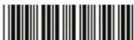
Return to USB default
Return to dongle USB communication.
(Communication dongle link required)
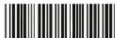
Return to Virtual COM Port default
Return to Virtual COM Port setting
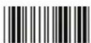
End Of Configuration
Wireless Mode
The scanner connects to the host via wireless connection. You may select SPP Master or SPP Slave for PC connection or select HID mode and Smart phone mode for smart phone connection.
SPP Slave Mode
In this mode, the scanner connects to the host /PC via wireless connection and performs like there's a serial connection. In SPP Slave mode, the scanner is discoverable from a remote device and it can request the scanner for connection. There are several ways to connect the wireless scanner to your PC. If you have your own applications please check their User's Manuals for pairing instructions.
To connect a wireless device to Window based system for the first time:
- Turn on the host computer and activate its wireless connection.
- Select "Add Bluetooth device". Or open the dialog Bluetooth devices and click "Add".
- Power on the scanner and program it with "SPP Slave mode" label.

Enable wireless SPP Slave mode.
Scanner SPP Slave enable
-
On Devices tab, click Add. This will open the Add Bluetooth Device Wizard.
-
Select the "My device is set up and ready to be found" checkbox, and then click Next.
-
The scanner should be on the list of discoverable devices. The default name of the scanner is "Z-325X BT" with address. Select the device and click "Next".
-
Select "Let me choose my own passkey" and enter the pin code. The default pin code is "12345678.
-
Click "Next" to connect the scanner to the host. A short beep should be heard upon connection.
End Of Configuration
Connect to PC [Window]
To connect a wireless device to Window XP for the first time:
- Turn on the host computer and activate its wireless connection.
- Select "Add wireless device". Or open the dialog BT devices and click "Add".
![Zebex Z-3250 - Connect to PC [Window] - 1](/content/2026/05/785993/images/911dc44bf99216ad12a0217ab710361325fa8f4a55eb1afe3eb823cf567b5765.jpg)
text_image
Control Panel File Edit View Favorites Tools Help Back Search Folders Address Control Panel Control Panel SwitchTo Category View See Also Windows Update Help and Support Accessibility Options Add Hardware Add or Remove Programs Administrative Tools Adobe Gamma Automatic Updates AvantGo Connect Bluetooth Configuration Bluetooth Devices Date and Time Display Folder Options Fonts Di-Game Controllers Internet Options Keyboard Mail Mouse Network Connections Phone and Modern Options Portable Media Devices Power Options Printers and Fees QuickTree Regional and Language Options Scanners and Cameras Scheduled Tasks Security Center SoundEffect Manager Sounds and Audio Devices Speech Synantec LiveUpdates System Tailiber and Start Menu User Accounts Windows Firewall Wireless Link Wireless Network Setup Wizard- Power on the scanner and program it with "Scanner SPP Slave enable" label from the previous page.
- In COM Ports page, click "Add". This will open the Add COM port window.
![Zebex Z-3250 - Connect to PC [Window] - 2](/content/2026/05/785993/images/9f71c4e83acb91795395767f9131d77250854d2501776ca6d3c54d7072e5e8f3.jpg)
text_image
Bluetooth Devices Devices Options COM Ports Hardware This computer is using the COM (serial) ports listed below. To determine whether you need a COM port, read the documentation that came with your Bluetooth device. Port Direction Name Add... Remove Learn more about Bluetooth COM ports OK Cancel Apply- Select "Outgoing (computer initiate the connection)", and then click "Browse".
![Zebex Z-3250 - Connect to PC [Window] - 3](/content/2026/05/785993/images/b6e2cdc820dd550bb114f7419632b61e55c4302909009eccc41bcd2487e7a248.jpg)
text_image
Add COM Port Select the type of COM (serial) port that you want to add: ○ Incoming (device initiates the connection) ○ Outgoing (computer initiates the connection) Device that will use the COM port: Browse... Service: Learn more about Bluetooth device COM ports. OK Cancel- The scanner should be on the list of discoverable devices. The default name of the scanner is "Z-325X BT". Select "Z-325X BT" and click "OK".
![Zebex Z-3250 - Connect to PC [Window] - 4](/content/2026/05/785993/images/212e9928f7680cf2b94e3b5ff00e7104efbe6c94922b67f95e2914b3dd2afea0.jpg)
text_image
WindowsCE New Device 2423-STELLANB New Device Other Devices E-3251BT(DD"BE"EE) New Device If you don't see the device that you want to add, make sure that it turned on. Follow the setup instructions that came with the device, and then click Search Again. Search Again OK Cancel- Write down the COM port number for later use.
![Zebex Z-3250 - Connect to PC [Window] - 5](/content/2026/05/785993/images/c3f36e7a7f8358fe8e7d12e3b489de256533066b4cdfb926fce86dfb0f097299.jpg)
text_image
Bluetooth Devices Devices Options COM Poits Hardware This computer is using the COM (serial) ports listed below. To determine whether you need a COM port, read the documentation that came with your Bluetooth device. Port Direction Name COM4 Outgoing Z-325( BT(DD:EE:EE) 'SPP Dev' Add... Remove Learn more about Bluetooth COM ports OK Cancel Apply- Select the Device tab to go back to the device page.
![Zebex Z-3250 - Connect to PC [Window] - 6](/content/2026/05/785993/images/b3f562d812429ebf6c1a27041fa79045460ff6f6876264b313a70f259ae59c07.jpg)
text_image
Bluetooth Devices Devices Options COM Ports Hardware Z-3251BT(DD:EE:EE) No passcode Add... Remove Properties OK Cancel Apply- A message should appear in the Windows Taskbar telling you a Bluetooth device is attempting to connect. Click on the message to open Add Bluetooth Device Wizard.
- Enter the pin code in the Add Bluetooth Device Wizard and click "Next". The default pin code is "12345678.
-
- Click "Ok" when the connection is established.
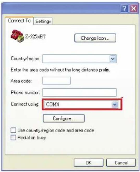
- Open HyperTerminal or other serial port programs and select the COM port you wrote down in the previous step and click "OK".
Remark: You do not wish to proceed via HyperTerminal, you can use serial
![Zebex Z-3250 - Connect to PC [Window] - 7](/content/2026/05/785993/images/c928951ed894ef3798f7cb88525c2440852785374f44d166e92da2a9a9fd5f16.jpg)
port program by clicking icon -> [Desktop\Communicat]
- Select the telephone icon to open the COM port.
![Zebex Z-3250 - Connect to PC [Window] - 8](/content/2026/05/785993/images/1f330af1e3b3c7a9517219d64173b6a5bb1047b93ef999f36d2ea124318bc7b5.jpg)
text_image
Connect To Settings Z-325xB7 Change Icon... Country/region: Enter the area code without the long-distance prefix. Area code: Phone number: Connect using: COM4 Configure... Use country/region code and area code Redial on busy OK Cancel![Zebex Z-3250 - Connect to PC [Window] - 9](/content/2026/05/785993/images/31af4c7b6ec6527aefa493a11a3502652c01879e9473d58c5874cc1ff8dfb119.jpg)
text_image
test - HyperTerminal File Edit View Call Transfer Help Disconnected Auto detect SCROLL CAPS NUM CaptureSPP Master Mode
To connect a wireless device to Window XP for the first time:
- Turn on the host computer and activate its wireless connection.
- Select "Add wireless device". Or open the dialog BT devices and click "Add".
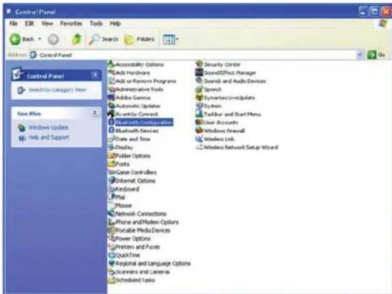
text_image
Control Panel File Edit View Favorites Tools Help Back Search Folders Address Control Panel Control Panel Switch to Category View See Also Windows Updates Help and Support Accessibility Options Add Hardware Add or Remove Programs Administrative Tools Adobe Gamma Automatic Updates AvantGo Connect Bluetooth Configuration Bluetooth Devices PDate and Time Display Folder Options Fonts To-Game Controllers Internet Options Keyboard Mail Mouse Network Connections Phone and Modern Options Portable Media Devices Power Options Printers and Frames QuickTime Regional and Language Options Scanners and Cameras Scheduled Tasks Security Center SoundEffect Manager Sounds and Audio Devices Speech Symantec LiveUpdates System Tailbar and Start Menu User Accounts Windows Firewall Wireless Link Wireless Network Setup Wizard- Power on the scanner and program it with "Scanner SPP Slave enable" label from the previous page.
- In COM Ports page, click "Add". This will open the Add COM port window.
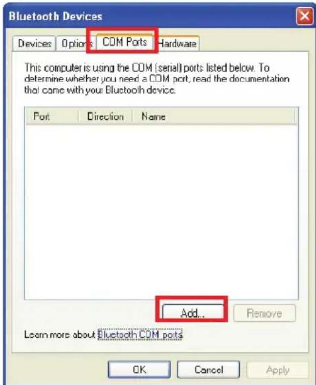
text_image
Bluetooth Devices Devices Options COM Ports Hardware This computer is using the COM (serial) ports listed below. To determine whether you need a COM port, read the documentation that came with your Bluetooth device. Port Direction Name Add... Remove Learn more about Bluetooth COM ports OK Cancel Apply- Select "Incoming (scanner initiate the connection)", and then click "OK".
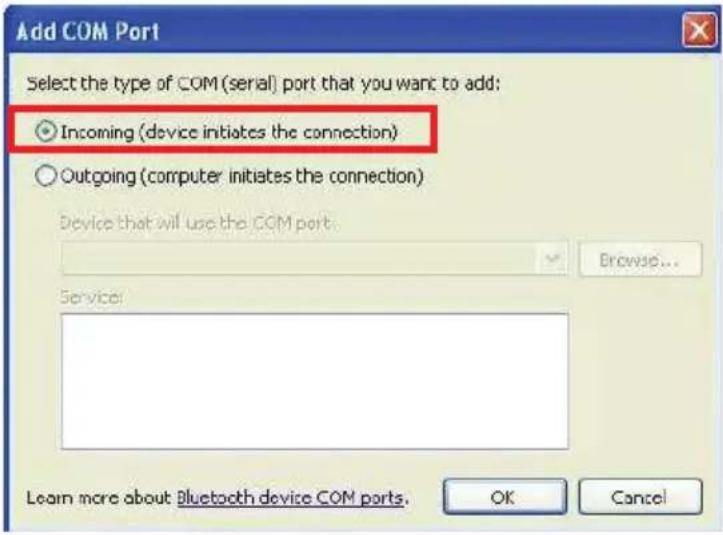
text_image
Add COM Port Select the type of COM (serial) port that you want to add: ○ Incoming (device initiates the connection) ○ Outgoing (computer initiates the connection) Device that will use the COM port. Browse... Service: Learn more about: Bluetooth device COM ports. OK Cancel- Write down the COM port number for later use.
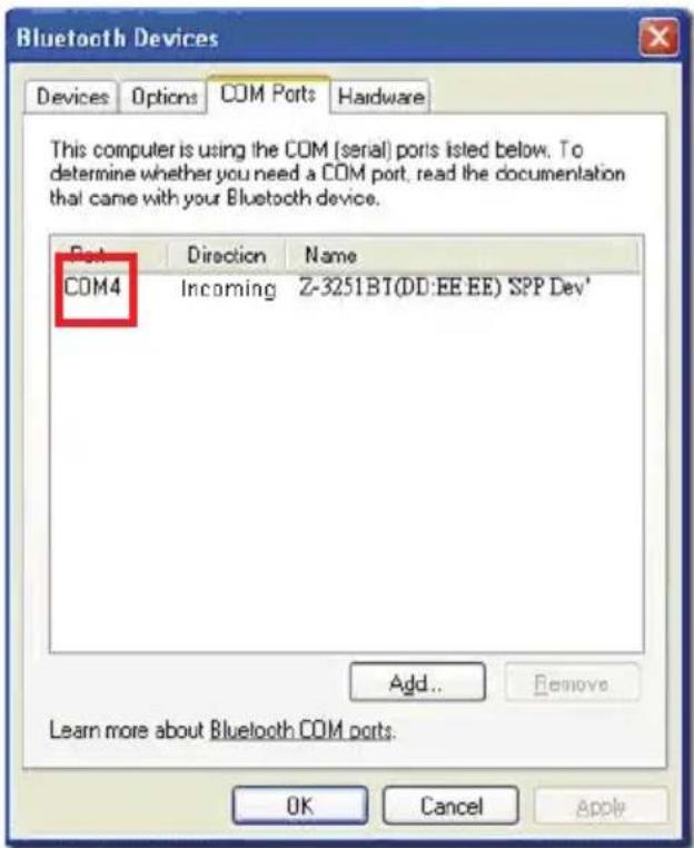
text_image
Bluetooth Devices Devices Options COM Ports Hardware This computer is using the COM (serial) ports listed below. To determine whether you need a COM port, read the documentation that came with your Bluetooth device. Port Direction Name COM4 Incoming Z-3251BT(DD:EE EE) 'SPP Dev' Add... Remove Learn more about Bluetooth COM ports. OK Cancel Apply- Select the Device tab to go back to the device page.
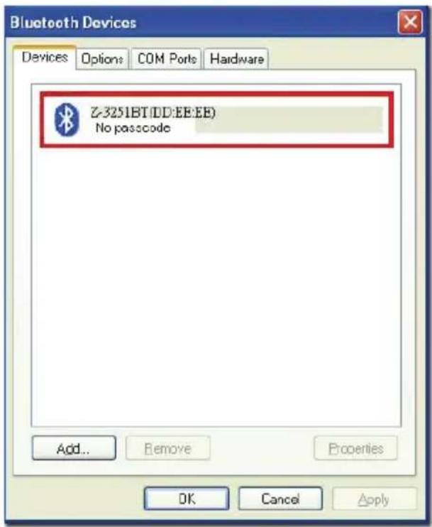
text_image
Bluetooth Devices Devices Options COM Ports Hardware Z-3251BT(DD:EE:EE) No passcode Add... Remove Properties OK Cancel Apply- Scan "Set device address" to set the address.
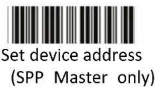
text_image
Set device address (SPP Master only)Set device address for SPP Master connection.
-
Use the ASCII table in Programming Guide to input the 12 digit device address. For example: if the address is "011B1345600", scan "0", "0", "1", "1", "B", "1", "3", "4", "5", "6", "0", "0" from ASCII barcode labels.
-
Scan "Confirm Setting" to store the address.
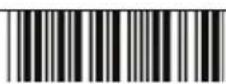
Confirm Setting (for address and pin code setting required)
-
Setup and input the pin code if necessary. Please see Setting Pin Code section for more details.
-
Scan "Required Pair with slave (SPP Master)" to begin pairing.
Required Pair with slave (SPP Master)
- A message should appear in the Windows Taskbar telling you a Bluetooth device is attempting to connect. Click on the message to open Add Bluetooth Device Wizard.
- Enter the pin code in the Add Bluetooth Device Wizard and click "Next". The default pin code is "12345678.
-
- Click "Ok" when the connection is established.
- Open HyperTerminal or other serial port programs and select the COM port you wrote down in the previous step and click "OK".
Remark: You do not wish to proceed via HyperTerminal, you can use serial

text_image
port program by clicking icon -> [C:\Users\jiahao.ZBT\ Desktop\Communicat]- Select the telephone icon to open the COM port.
text_image
Connect To Settings Z-325xB7 Change Icon... County/region: Enter the area code without the long distance prefix. Area code: Phone number: Connect using: COM4 Configure... Use country/region code and area code Redial on busy OK Cancel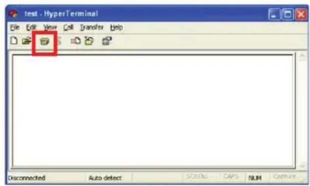
text_image
test - HyperTerminal File Edit View Call Transfer Help Disconnected Auto detect SCROLL CAPS NUM Capture
Start Of Configuration
HID mode
In HID mode, the scanner connects to the host /PC via wireless connection and performs like there's a keyboard connection. The scanner initiates the connection to the remote device.
- Power on the scanner and program it with "HID Mode". To connect a smart mobile phone (for example, iPhone, Android), the Smart phone mode must also be enabled. Power off the scanner when the setting is done.
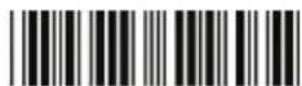
HID mode
Enable wireless HID keyboard emulation
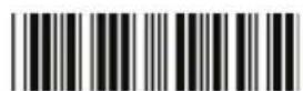
Smart phone mode
For smart phone mode (HID MODE must also be enabled).
- Enable wireless connection on your host and follow the instructions in your host to set it to discover other wireless devices in its surrounding.
- The scanner should be on the list of discoverable devices. The default name of the scanner is "Z-325X BT". You will be prompt to enter paring pin code. Select "Z-325X BT" and input the pin code that appears on your mobile device to connect scanner to the phone.
- Scan the Enter barcode to confirm. A short beep should be heard upon connection.
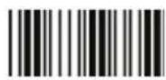
Enter
Full ASCII ---CR
Function key----"Enetr(num.)"
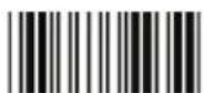
End Of Configuration
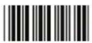
Start Of Configuration
Setting Pin Code
- To change the pin code, use the "Set pin code" setting. Default is "12345678".
- Use the ASCII table in Programming Guide to input the new code (must be at least 4 digits and not more than 8 numeric digits).
- Scan "Save Setting" to store the pin code.
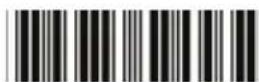
Set pin code
Set pin code (SPP Master only)
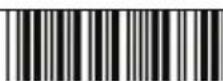
Confirm Setting (for address and pin code setting required)

Please check the User's Manual from your PC for device address and pin code.
Deleting pin code
To delete pin code, use the "Delete pin code setting".
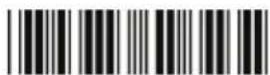
Delete pin code
Delete the stored pin code.
Reset Name
To change the scanner name back to the default name "Z-325x BT" use the "Default device name" setting.
Default device name
Change device name back to default "Z-325x BT".
End Of Configuration
Start Of Configuration
Setting Name
- To change the name displayed when the scanner is discovered, scan the "Friendly device name set" label. Default name is "Z-325X BT".
- Use the ASCII table in Programming Guide to input the name (Max.12 digits).
- Scan "Confirm Setting" to store the new name.
text_image
Friendly device name setChange the display name when scanner is discovered.
Confirm Setting (for address and pin code setting required)
Wireless Discovery
Use the following settings to show or hide the device from wireless discovery.
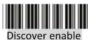
Make scanner visible to wireless device.
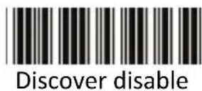
Make scanner invisible to wireless device.
End Of Configuration
Secure Simple Pairing
The scanner connects to the host via SPP Slave, SPP Master, HID, HID Keyboard, or HID Multi Media Keyboard mode without pin code when the host supports it.
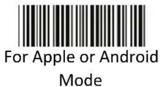
text_image
For Apple or Android ModeEnable Apple or Android mode
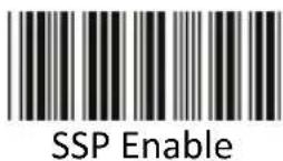
Enable Secure Simple Pairing mode
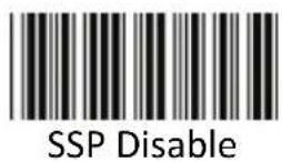
Disable Secure Simple Pairing mode
End Of Configuration
Data Transmit Method
The data transfer method includes three types: Normal (default), Out-of-Range Mode, and Batch Mode. Users may modify this setting according to their preferences.
Normal
When the scanner is within the connection range, the scanned data will be transferred to the host computer immediately. If the scanner is out of its connecting range, the scanner does not send or store any data.
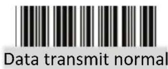
text_image
Data transmit normalBatch mode is disabled.
Out of Range
Scanned data are stored when scanner is out of its wireless communication range. When scanner is back into its communication range or re-connected, the stored data are sent when scanning next barcode label.
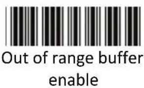
text_image
Out of range buffer enableEnable out of range mode.
End Of Configuration
Start Of Configuration
Batch Mode
Whether within the connection range or not, in batch mode, the scanner stores all scanned data that will be transferred to the host computer after scanning “Send Batch Data” label.
Number of storable bar codes = 61,365 bytes of memory / (number of characters in the bar code +2)
Batch mode
Note: Scanner LED indicator will not flash while waiting for connection in this mode.
Clearing Batch
Use the settings in this section to clear the stored data.
Clear batch data after send
Saved data are cleared after they are transferred to the host.
Clear batch data by scanning "Delete batch data" label
Scan this label then scan "Confirm Setting" to delete the stored batch data.
Delete batch data
Same as previous setting but with alert sound.
Confirm Setting (for address and pin code setting required)
End Of Configuration
Start Of Configuration
Batch Transfer
Use the settings in this section to setup batch transfer.
Send Batch Data By
Scanning Label

Send Batch Data on line USB cable contact
Scanning this label automatically exits you from the Programming Mode. Press and hold the trigger for over 1 second to send the data.
Data is ready to be transferred upon USB connection. Press and hold the trigger for over 1 second to send the data.
Batch Mode Sounds Settings
Use the settings in this section to setup the sound.
Out of range resend data with beeper sound
Add beeper sound when resending data in Out of range mode.
Out of range resend data without beeper sound in Out of range mode.
No beeper sound when resending data
Send Batch Data without beep
No beep when sending data. Good-read LED will light up until the transfer is done.
Send Batch Data with Beep
Beep sound when sending data. Good-read LED will light up until the transfer is done.
End Of Configuration
System Function Settings
Default values are highlighted in grey background.
Start Of Configuration
Barcode Value Description
| Return scanner to factory defaults | |
| Return dongle host to factory defaults | |
| Return to USB default(Communication dongle link required) | |
| Return as USB-virtual COM port default(Communication dongle link required) | |
| Return as OPOS port default | |
| Function Button EnableEnable the function/off button | |
| Function Button DisableDisable the function/off button |
End Of Configuration
Start Of Configuration
Barcode Value Description
Display firmware version
Abort
(exit programming mode without any updates)
Scan Mode
Trigger mode
The scanner becomes inactive as soon as the data is transmitted. It must be triggered to become active again.
Auto scan mode
The scanner is still active after the data is transmitted but the successive transmission of the same barcode is not allowed when the trigger switch is pressed again.
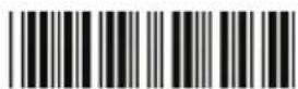
Alternate mode
The scanner illumination alternates between on and off when the trigger switch is pressed.
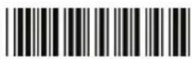
Presentation mode
Also called auto trigger mode. The scanner is inactive but will automatically detect barcodes presented in the scan zone and become active.
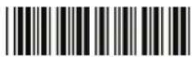
Idle mode enable
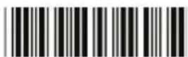
Idle mode disable
Disable Idle mode.
End Of Configuration
Radio Communication Setting
Dongle Host mode
Dongle Host mode enable
Enable dongle mode with this setup.
Unlock pairing mode
In this mode, the scanner can pair with another dongle when disconnected.
Lock pairing mode.
In this mode, the scanner can not pair with another dongle.
Undo pairing
Undo the pairing between the dongle and the scanner.
USB Online mode
USB online scan disable
USB online scan enable

USB online scan, Ignore radio communication
End Of Configuration
Start Of Configuration
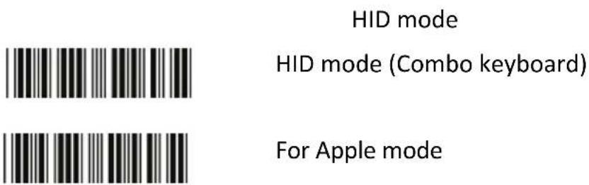
text_image
HID mode HID mode (Combo keyboard) For Apple mode
SPP Master/Slave mode Scanner SPP Master enable SPP Master (Connect wireless address "BxxxxxxxxxxxxxT" in CODE39 format) Scanner SPP Slave enable
Setting wireless address (SPP Master only) Set PIN code (SPP Master only)
Device Setting
Show device address after friendly name enabled Enable showing device address xx:xx:xx after device name during discovery Show device address after device friendly name disabled Disable showing device address xx:xx:xx after device name during discovery
End Of Configuration
 | Start Of Configuration |
 | Default Device name |
 | Friendly device name set |
 | Delete pin code |
 | Confirm Setting (for address, device name, and pin code setting required) |
 | Required Pair with slave (SPP Master) |
 | Discover enable |
 | Discover disable |
 | Encryption enable |
 | Encryption disable |
 | Data communication without protocol |
 | Data communication with ACK/NAK protocol |
 | Data communication with Packing protocol |
End Of Configuration
Start Of Configuration
Data Transmit Mode
Data transmit normal
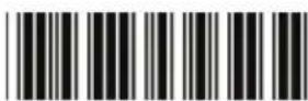
Out of range buffer enable
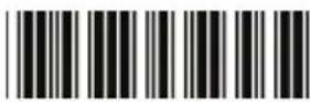
Batch mode
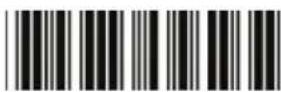
Send Batch Data By Scanning Label
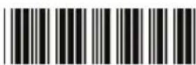
Clear batch data after send
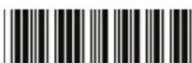
Clear batch data by scanning "Delete batch data" label
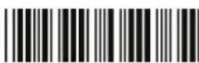
Delete batch data
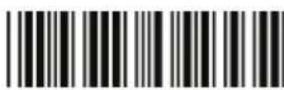
Send Batch Data on line USB cable contact.

Send Batch data on dongle
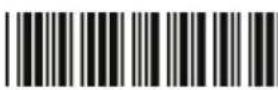
Out of range resend data with beeper sound
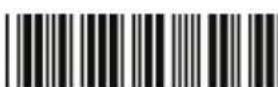
Out of range resend data without beeper sound
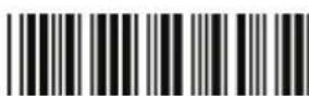
Send Batch Data without Beep
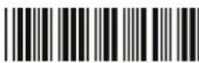
Send Batch Data with Beep
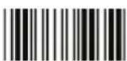
End Of Configuration
Start Of Configuration
Radio protocol communication parameter
Radio protocol timeout= 3 sec
Radio protocol timeout= 5 sec
Radio protocol timeout =8 sec
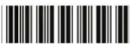
Radio protocol timeout= 10 sec
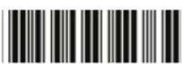
Radio protocol timeout =13 sec
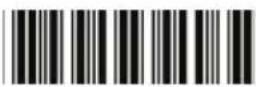
Radio protocol timeout =16 sec
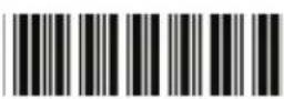
Radio protocol timeout= 20 sec
End Of Configuration
Start Of Configuration
Power off timeout parameter

Power off timeout=5 min

Power off timeout=10 min
Power off timeout=20 min
Power off timeout=30 min
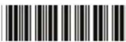
Power off timeout=1 hr
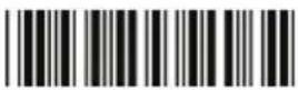
Power Off timeout : 2 hr
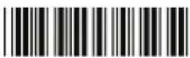
Power Off timeout : 4 hr
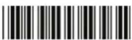
Power Off timeout : 6 hr
Power Off timeout : 8 hr
End Of Configuration
Start Of Configuration
Power Always On
Power off by scanning this label
Link beeper enable
Link beeper disable
Power-up beeper enable
Power-up beeper disable
Same Code Delay
50 msec
100 msec
200 msec
300 msec
End Of Configuration
Start Of Configuration
400 msec
500 msec
600 msec
700 msec
800 msec
1000 msec

Infinite
End Of Configuration
Start Of Configuration
Operation Function Setting
Good Read Beeper Tone Selection
Medium beeper tone
High beeper tone
Low beeper tone
Speaker disable
End Of Configuration
Start Of Configuration
Beeper duration Selection
Long
Medium
Short
Ultra Short
Ultra Long
End Of Configuration
Start Of Configuration
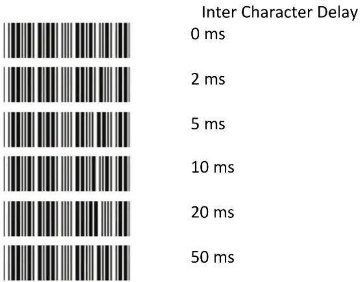
bar
| Inter Character Delay | Value | | --------------------- | ----- | | 0 ms | 50 | | 2 ms | 20 | | 5 ms | 10 | | 10 ms | 5 | | 20 ms | 2 | | 50 ms | 0 |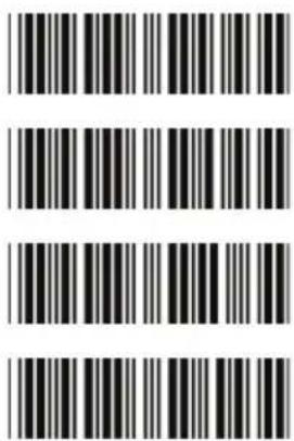
text_image
Image of a barcode with vertical black and white stripes, no text or symbols present.
text_image
Inter Message Delay 0 ms 100 ms 500 ms 1000 ms
End Of Configuration
Start Of Configuration
Interface Settings
RS-232C Interface Setting
Start Of Configuration
Message Terminator
RS-232 message terminator—none
RS-232 message terminator—CR/LF
RS-232 message terminator—CR
RS-232 message terminator—LF
RS-232 message terminator—H tab
RS-232 message terminator—STX/ETX
RS-232 message terminator—EOT
End Of Configuration
Start Of Configuration
USB Interface Setting
| USB Setting | |
| International Keyboard mode ( ALT method) | |
| Keyboard language support---USA | |
| Keyboard language support---UK send scan code | |
| Keyboard language support---GERMANY | |
| Keyboard language support---FRENCH send scan code | |
| Keyboard language support---SPANISH send scan code | |
| Keyboard language support---ITALIAN send scan code | |
| Keyboard language support---Switzerland send scan code | |
| Keyboard language support---Belgium send scan code | |
| Keyboard language support---Japanese | |
| Capital lock on | |
| Capital lock off | |
| Function key emulation enable | |
| Function key emulation disable | |
| Send number as normal data | |
| Send number as keypad data | |

End Of Configuration
Start Of Configuration
Message Terminator
Keyboard terminator---none
Keyboard terminator---Enter
Keyboard terminator---H-TAB
End Of Configuration
Smart Phone Software Keypad Control Setting
Smart Phone Software Keypad Control

Multi-media keyboard mode
- This option enables Multi-media keyboard mode
Software keypad enable/disable
- This option enable or disable Software keypad
To enable/disable Software keyboard:
- Scan the Start Of Configuration barcode.
- Scan the Multi-media keyboard mode barcode.
- Scan the End Of Configuration barcode.
- Connect the scanner with a smart phone. Please see HID mode for instructions.
- With Multi-media keyboard mode enabled and smart phone connection made, you may scan the Software keypad enable/disable barcode to enable or disable the Software keypad.
The Symbologies
Codabar Parameter Setting
Barcode
Value
RC02
Barcode Label Description
Codabar enable


Codabar start/stop character transmission — none

Codabar start/stop character transmission — A,B,C,D

Codabar start/stop character transmission — DC1\~DC4

Codabar start/stop character transmission — a/t,b/n,c/*,d/e
Codabar maximum length setting

Codabar minimum length setting
SET
Confirm to save this setting (required for reading full ASCII table and length setting)
End Of Configuration
Start Of Configuration
Barcode Value
| CB13 | No check character |
| CB14 | Validate modulo 16,but don't transmit |
| CB15 | Validate modulo 16 and transmit |
| DC50 | Codabar data redundant check=off |
| DC51 | Codabar data redundant check=1 |
| DC52 | Codabar data redundant check=2 |
| DC53 | Codabar data redundant check=3 |
End Of Configuration
Start Of Configuration
Code 39 Parameter Setting
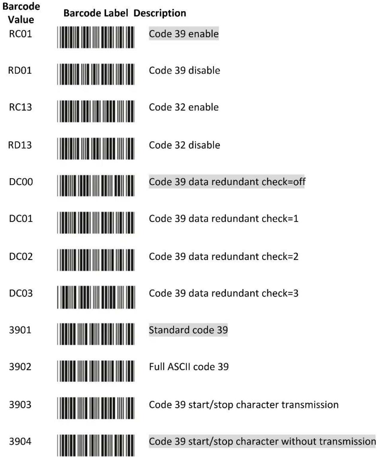
bar
| Barcode Value | Barcode Label Description | Code | | ------------ | ------------------------- | ---- | | RC01 | White barcode | 39 | | RD01 | White barcode | 39 | | RC13 | White barcode | 32 | | RD13 | White barcode | 32 | | DC00 | White barcode | 39 | | DC01 | White barcode | 39 | | DC02 | White barcode | 39 | | DC03 | White barcode | 39 | | 3901 | White barcode | Standard code 39 | | 3902 | White barcode | Full ASCII code 39 | | 3903 | White barcode | Code 39 start/stop character transmission | | 3904 | White barcode | Code 39 start/stop character without transmission |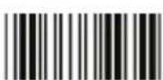
End Of Configuration
Start Of Configuration
Barcode Value
| 3905 | Code 39 check digit calculate and transmit |
| 3906 | Code 39 check digit calculate but without transmit |
| 3907 | No check character |
| 3908 | Code 39 maximum length setting |
| 3909 | Code 39 minimum length setting |
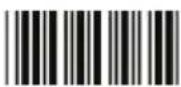
SET
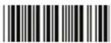
Confirm to save this setting (required for reading full ASCII table and length setting)
3912 Code 32 (italian pharmacy) transmit "A" character
3913 Code 32 (Italian pharmacy) without transmit "A" character

End Of Configuration

Start Of Configuration
Code 93 Parameter Setting
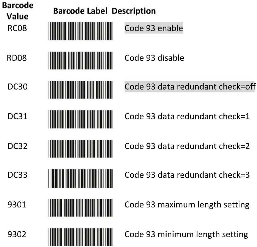
bar
| Barcode Value | Barcode Label Description | Code 93 Status | | ------------- | ------------------------- | -------------- | | RC08 | [Image] | Enable | | RD08 | [Image] | Disable | | DC30 | [Image] | Data redundant check=off | | DC31 | [Image] | Data redundant check=1 | | DC32 | [Image] | Data redundant check=2 | | DC33 | [Image] | Data redundant check=3 | | 9301 | [Image] | Maximum length setting | | 9302 | [Image] | Minimum length setting |SET

Confirm to save this setting (required for reading full ASCII table and length setting)
9303 Code 93 check digit calculate but without transmit
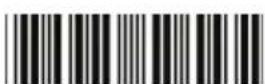
Code 93 check digit not calculate and without transmit
9305 Code 93 check digit calculate and transmit
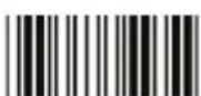
End Of Configuration
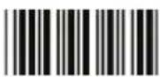
Start Of Configuration
Code 128 Parameter Setting
| Barcode Value | Barcode Label | Description |
| RC06 | Code 128 enable | |
| RD06 | Code 128 disable | |
| RC10 | EAN-128 enable | |
| RD10 | EAN-128 disable | |
| DC40 | Code 128 data redundant check=off | |
| DC41 | Code 128 data redundant check=1 | |
| DC42 | Code 128 data redundant check=2 | |
| DC43 | Code 128 data redundant check=3 | |
| 1803 | No check character | |
| 1804 | Calculate but not transmit | |
| 1805 | Calculate and transmit | |
| 1806 | Code 128 maximum length setting | |
| 1807 | Code 128 minimum length setting | |
| SET | Confirm to save this setting (required for reading full ASCII table and length setting) |
End Of Configuration
Start Of Configuration
Chinese Post Code Parameter Setting
| Barcode Value | Barcode Label | Description |
| RC05 | Chinese post code enable | |
| RD05 | Chinese post code disable | |
| DC60 | Chinese post code data redundant check=off | |
| DC61 | Chinese post code data redundant check=1 | |
| DC62 | Chinese post code data redundant check=2 | |
| DC63 | Chinese post code data redundant check=3 | |
| SZ01 | Chinese post code maximum length setting | |
| SZ02 | Chinese post code minimum length setting |
SET
Confirm to save this setting (required for reading full ASCII table and length setting)
End Of Configuration
Start Of Configuration
MSI/Plessy Parameter Setting
| Barcode Value | Barcode Label | Description |
| RC14 | MSI enable | |
| RD14 | MSI disable | |
| DC70 | MSI data redundant check= off | |
| DC71 | MSI data redundant check=1 | |
| DC72 | MSI data redundant check=2 | |
| DC73 | MSI data redundant check=3 | |
| MS01 | MSI/Plessy maximum length setting | |
| MS02 | MSI/Plessy minimum length setting | |
| SET | Confirm to save this setting (required for reading full ASCII table and length setting) | |
| MS03 | MSI/Plessy double check digit calculate but not transmit | |
| MS04 | MSI/Plessy double check digit without calculate and transmit | |
| MS05 | MSI/Plessy double check digit calculate but only first digit transmit | |
| MS06 | MSI/Plessy double check digit calculate and both transmit | |
| MS07 | MSI/Plessy single check digit calculate but without transmit | |
| MS08 | MSI/Plessy single check digit calculate and transmit | |
End Of Configuration
Start Of Configuration
Code 11 Interface Setting
| Barcode Value | Barcode Label | Description |
| RC07 | Code 11 enable | |
| RD07 | Code 11 disable | |
| 1101 | Code 11 maximum length setting | |
| 1102 | Code 11 minimum length setting | |
| SET | Confirm to save this setting (required for reading full ASCII table and length setting) | |
| 1103 | Code 11 one check digit verification | |
| 1104 | Code 11 two check digit verification | |
| 1105 | Two Check for Code 11 check digit if code length is longer than 10 characters | |
| 1106 | Disable verification | |
| 1107 | Code 11 check digit transmitted | |
| 1108 | Code 11 check digit not transmitted | |
End Of Configuration
Start Of Configuration
ITF 2 of 5 Parameter Setting
| Barcode Value | Barcode Label | Description |
| RC04 | ITF 2 of 5 enable | |
| RD04 | ITF 2 of 5 disable | |
| RC09 | IATA code enable | |
| RD09 | IATA disable | |
| DC80 | ITF 25 data redundant check=off | |
| DC81 | ITF25 data redundant check=1 | |
| DC82 | ITF25 data redundant check=2 | |
| DC83 | ITF25 data redundant check=3 | |
| IT03 | ITF 2 of 5 no check character | |
| IT04 | ITF 2 of 5 check digit calculate and transmit | |
| IT05 | ITF 2 of 5 check digit calculate but without transmit |
End Of Configuration
Start Of Configuration
Barcode Value
| IT01 | ITF 2 of 5 code maximum length setting |
| IT02 | ITF 2 of 5 code minimum length setting |
| IT06 | ITF 2 of 5 one fixed length setting |
| IT07 | ITF 2 of 5 two fixed length setting |
SET
Confirm to save this setting (required for reading full ASCII table and length setting)
IT08
ITF 2 of 5 length variable
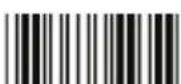
End Of Configuration
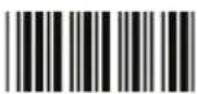
Start Of Configuration
Standard 2 of 5 Parameter Setting
Barcode Value
RC22
Barcode Label Description
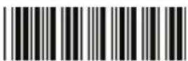
Standard 2 of 5 code enable
RD22
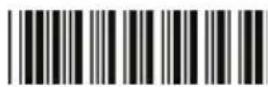
Standard 2 of 5 code disable
D051
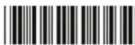
Standard 2 of 5 code maximum length setting
D052
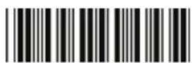
Standard 2 of 5 code minimum length setting
SET
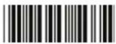
Confirm to save this setting (required for reading full ASCII table and length setting)
D053
Standard 2 of 5 code no check character
D054
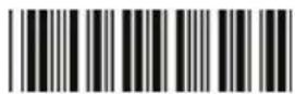
Standard 2 of 5 code check digit calculate and transmit
D055
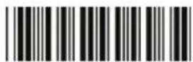
Standard 2 of 5 code check digit calculate but without transmit
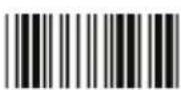
End Of Configuration
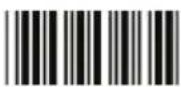
Start Of Configuration
Industrial 2 of 5 Parameter Setting
Barcode Value
| RC21 | 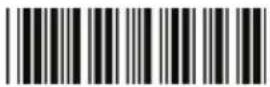 | Industrial 2 of 5 code enable |
| RD21 |  | Industrial 2 of 5 code disable |
| D251 |  | Industrial 2 of 5 code maximum length setting |
| D252 |  | Industrial 2 of 5 code minimum length setting |
SET
Confirm to save this setting (required for reading full ASCII table and length setting)
D253 Industrial 2 of 5 code no check character
D254 Industrial 2 of 5 code check digit calculate and transmit
D255 Industrial 2 of 5 code check digit calculate but without transmission
End Of Configuration
UPC/EAN/JAN Parameter Setting
Barcode Value
| RC11 | EAN convert to ISSN/ISBN enable | |
| RD11 | EAN convert to ISSN/ISBN disable | |
| RC03 | UPC/EAN/JAN enable | |
| RD03 | UPC/EAN/JAN disable | |
| UE01 | UPC/EAN/JAN all enable | |
| UE02 | EAN-8 or EAN-13 enable | |
| UE03 | UPC-A and EAN-13 enable | |
| UE04 | UPC-A and UPC-E enable | |
| UE05 | UPC-A enable | |
| UE06 | UPC-E enable | |
| UE07 | EAN-13 enable | |
| UE08 | EAN-8 enable | |
| UE09 | UPC/EAN Addendum disable |
Start Of Configuration
Barcode Value
| UE10 | Add on 5 only |
| UE11 | Add on 2 only |
| UE12 | Add on 2 or 5 |
| UE13 | Force UPC-E to UPC-A format enable |
| UE14 | Force UPC-E to UPC-A format disable |
| UE15 | Force UPC-A to EAN-13 format enable |
| UE16 | Force UPC-A to EAN-13 format disable |
| UE44 | Force EAN-8 to EAN-13 format enable |
| UE45 | Force EAN-8 to EAN-13 format disable |
| UE17 | Transmit UPC-A check digit enable |
| UE18 | Transmit UPC-A check digit disable |
| UE19 | Transmit UPC-E leading character enable |
| UE20 | Transmit UPC-E leading character disable |
| UE21 | Transmit UPC-E check digit enable |
| UE22 | Transmit UPC-E check digit disable |
End Of Configuration
Barcode Value
| UE23 | Transmit EAN-8 check digit enable | |
| UE24 | Transmit EAN-8 check digit disable | |
| UE25 | Transmit EAN-13 check digit enable | |
| UE26 | Transmit EAN-13 check digit disable | |
| UE27 | Transmit UPC-A leading character enable | |
| UE28 | Transmit UPC-A leading character disable | |
| UE30 | Add-on format with separator | |
| UE31 | Add-on format without separator | |
| UE60 | EAN-13 country code first "0" can be transmitted | |
| UE61 | EAN-13 country code first:"0" can't be transmitted | |
| UE66 | EAN-13 with first 0 ID code same as "UPC-A" | |
| UE67 | EAN-13 with first 0 ID code same as "EAN-13" | |
| DC10 | UPC-A data redundant check=off | |
| DC11 | UPC-A data redundant check=1 |
Start Of Configuration
Barcode Value
Barcode Label Description
| DC12 | UPC-A data redundant check=2 | |
| DC13 | UPC-A data redundant check=3 | |
| DC14 | UPC-E data redundant check=off | |
| DC15 | UPC-E data redundant check=1 | |
| DC16 | UPC-E data redundant check=2 | |
| DC17 | UPC-E data redundant check=3 | |
| DC20 | EAN-13 data redundant check=off | |
| DC21 | EAN-13 data redundant check=1 | |
| DC22 | EAN-13 data redundant check=2 | |
| DC23 | EAN-13 data redundant check=3 | |
| DC24 | EAN-8 data redundant check=off | |
| DC25 | EAN-8 data redundant check=1 | |
| DC26 | EAN-8 data redundant check=2 | |
| DC27 | EAN-8 data redundant check=3 | |
| UE32 | EAN/UPC +add-on (none mandatory) | |
| UE33 | EAN/UPC +add-on (mandatory) |
End Of Configuration
Start Of Configuration
UE35
EAN/UPC +add-on mandatory for 978/977 bookland (Supplement requirement, not sent for other)
UE38
EAN/UPC +addon mandatory for 978/977 bookland (Supplement requirement, optional for other)
UE42
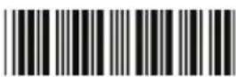
EAN/UPC +addon mandatory for 491 Japanese bookland (Supplement requirement, not sent for other)
UE43
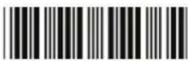
EAN/UPC +addon mandatory 491 Japanese bookland (Supplement requirement, optional for other)
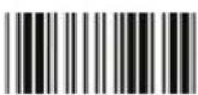
End Of Configuration
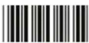
Start Of Configuration
Telepen Parameter Setting
Barcode Value
RC25
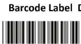
text_image
Barcode Label DTelepen enable
RD25
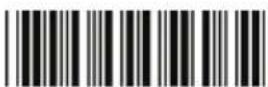
Telepen disable
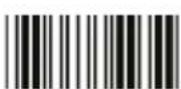
TE03
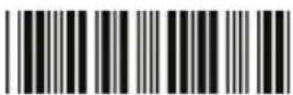
Telepen numeric mode enable
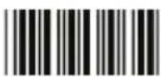
TE04
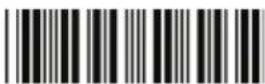
AIM Telepen enable
End Of Configuration
Start Of Configuration
Matrix 2 of 5 Parameter Setting
Barcode Value
RC12
Barcode Label Description
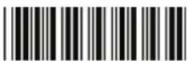
Matrix 2 of 5 enable
RD12
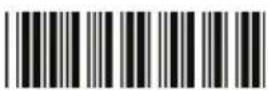
Matrix 2 of 5 disable
D151
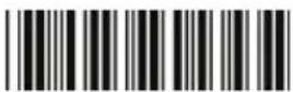
Matrix 2 of 5 maximum length setting
D152
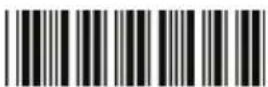
Matrix 2 of 5 minimum length setting
SET
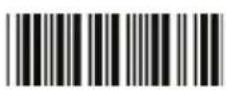
Confirm to save this setting (required for reading full ASCII table and length setting)
D153
Matrix 2 of 5 no check character
D154
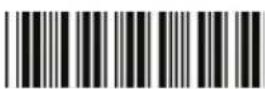
Matrix 2 of 5 check digit calculate and transmit
D155
Matrix 2 of 5 check digit calculate but without transmission
End Of Configuration

Start Of Configuration
GS1 DataBar Parameter Setting
There are 7 kinds of barcodes in the GS1 DataBar family and they are categorized into three groups. Barcode types in the same group use the same barcodes for setting.
| Group | Representative | Contents |
| Group 1 GS1 | DataBar Omnidirectional(Formally RSS-14) | GS1 DataBar OmnidirectionalGS1 DataBar TruncatedGS1 DataBar StackedGS1 DataBar Stacked Omnidirectional |
| Group 2 GS1 | DataBar Limited(Formally RSS Limited) | GS1 DataBar Limited |
| Group 3 GS1 | DataBar Expanded(Formally RSS Expanded) | GS1 DataBar ExpandedGS1 DataBar Expanded Stacked |
GS1 DataBar Omnidirectional (Formally RSS-14)
| Barcode Value | Barcode Label | Description |
| RC15 | GS1 DataBar Omnidirectional enable | |
| RD15 | GS1 DataBar Omnidirectional disable | |
| SS00 | Transmit GS1 DataBar Omnidirectional check digit | |
| SS01 | Do not transmit GS1 DataBar Omnidirectional check digit | |
| SS02 | Transmit GS1 DataBar Omnidirectional application ID (01) | |
| SS03 | Do not transmit GS1 DataBar Omnidirectional application ID (01) | |
| SS05 | GS1 DataBar Omnidirectional /EAN-128 emulation enable | |
| SS04 | GS1 DataBar Omnidirectional /EAN-128 emulation disable |
End Of Configuration
GS1 DataBar Limited (Formally RSS Limited)
| Barcode Value | Barcode Label | Description |
| RC16 | GS1 DataBar Limited enable | |
| RD16 | GS1 DataBar Limited disable | |
| SS10 | Transmit GS1 DataBar Limited check digit | |
| SS11 | Don’t transmit GS1 DataBar Limited check digit | |
| SS12 | Transmit GS1 DataBar limited application ID (01) | |
| SS13 | Do not transmit GS1 DataBar limited application ID |
GS1 DataBar Expanded (Formally RSS Expanded)
| Barcode Value | Barcode Label | Description |
| RC17 | GS1 DataBar Expanded enable | |
| RD17 | GS1 DataBar Expanded disable | |
| SS07 | GS1 DataBar Expanded/EAN-128 emulation enable | |
| SS06 | GS1 DataBar Expanded/EAN-128 emulation disable | |
| SS08 | GS1 DataBar Expanded check digital enable | |
| SS09 | GS1 DataBar Expanded check digital disable | |
| SS16 | Transmit GS1 DataBar Expanded application ID (01) | |
| SS17 | Do not transmit GS1 DataBar Expanded application ID |
Data Editing
Identifier Code
Barcode Value
| IS00 | Disable identifier code |
| IS01 | Enable identifier code table as factory standard |
| IS03 | Enable identifier code table as AIM standard. |
| CI01 | Code 39 identifier code setting |
| CI02 | ITF 2 of 5 identifier code setting |
| CI03 | Chinese Post Code identifier code setting |
| CI04 | UPC-E identifier code setting |
| CI05 | UPC-A identifier code setting |
| CI06 | EAN-13 identifier code setting |
| CI07 | EAN-8 identifier code setting |
SET
Confirm to save this setting (required for reading full ASCII table and length setting)
End Of Configuration
Start Of Configuration
Barcode Value
Barcode Label Description
| CI08 | Codabar identifier code setting |
| CI09 | Code 128 identifier code setting |
| CI10 | Code 93 identifier code setting |
| CI11 | MSI identifier code setting |
| CI12 | GS1 DataBar Omnidirectional id |
| CI13 | GS1 DataBar Limited identifier co |
| CI14 | GS1 DataBar expanded identifier |
| CI15 | Industrial 2 of 5 identifier code s |
| CI16 | Code 11 Identifier code setting |
| CI17 | Standard 2 of 5 identifier code se |
| CI18 | Matrix 2 of 5 identifier code sett |
End Of Configuration
Start Of Configuration
Header and Trailer
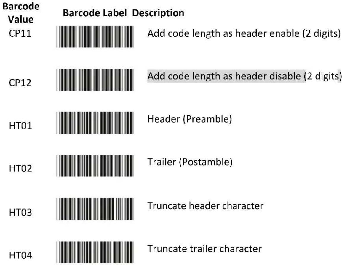
bar
| Barcode Value | Barcode Label Description | Annotation | | ------------- | ------------------------- | ---------- | | CP11 | [Image] | Add code length as header enable (2 digits) | | CP12 | [Image] | Add code length as header disable (2 digits) | | HT01 | [Image] | Header (Preamble) | | HT02 | [Image] | Trailer (Postamble) | | HT03 | [Image] | Truncate header character | | HT04 | [Image] | Truncate trailer character |SET
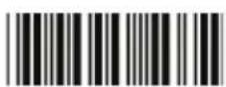
Confirm to save this setting (required for reading full ASCII table and length setting)
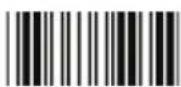
End Of Configuration
Full ASCII Code 39 Table
| Code 39 ASCII | Hexa-code | Code 39 ASCII | Hexa-code | ||
| Full ASCII ---NUL 00 | Full ASCII ---SIFunction key----“Shift” | 0F | |||
| Full ASCII ---SOHFunction key----“Ins” | 01 | Full ASCII ---DLEFunction key----“5(num)” | 10 | ||
| Full ASCII ---STXFunction key----“Del” | 02 | Full ASCII ---DC1Function key----“F1” | 11 | ||
| Full ASCII ---ETXFunction key----“Home” | 03 | Full ASCII ---DC2Function key----“F2” | 12 | ||
| Full ASCII ---EOTFunction key----“End” | 04 | Full ASCII ---DC3Function key----“F3” | 13 | ||
| Full ASCII ---ENQFunction key----“Uparrow” | 05 | Full ASCII ---DC4Function key----“F4” | 14 | ||
| Full ASCII ---ACKFunction key----“Downarrow” | 06 | Full ASCII ---NAKFunction key----“F5” | 15 | ||
| Full ASCII ---BELFunction key----“Leftarrow” | 07 | Full ASCII ---SYNFunction key----“F6” | 16 | ||
| Full ASCII ---BSFunction key----“Backspace” | 08 | Full ASCII ---ETBFunction key----“F7” | 17 | ||
| Full ASCII ---HTFunction key----“TAB” | 09 | Full ASCII ---CANFunction key----“F8” | 18 | ||
| Full ASCII ---LFFunction key----“Enter(alpha numeric)” | 0A | Full ASCII ---ENFunction key----“F9” | 19 | ||
| Full ASCII ---VTFunction key----“rightarrow” | 0B | Full ASCII ---SUBFunction key----“F10” | 1A | ||
| Full ASCII ---FFFunction key----“PgUp” | 0C | Full ASCII ---ESCFunction key----“F11” | 1B | ||
| Full ASCII ---CRFunction key----“Enetr(num.)” | 0D | Full ASCII ---FSFunction key----“F12” | 1C | ||
| Full ASCII ---SOFunction key----“PgDn” | 0E | Full ASCII ---GSFunction key----“ESC” | 1D | ||
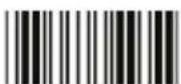
End Of Configuration
Start Of Configuration
Full ASCII Code 39 Table (continued)
| Code 39 ASCII | Hexa-code | Code 39 ASCII | Hexa-code | ||
| Full ASCII ---RSFunction key----“CTL(L)” | 1E | Full ASCII --- 2D | |||
| Full ASCII ---USFunction key----“ALT(L)” | 1F | Full ASCII ---. 2E | |||
| Full ASCII ---SP 20 | Full ASCII ---/ 2F | ||||
| Full ASCII ---! 21 | Full ASCII ---0 30 | ||||
| Full ASCII ---“ 22 | Full ASCII ---1 31 | ||||
| Full ASCII ---# 23 | Full ASCII ---2 32 | ||||
| Full ASCII ---$ 24 | Full ASCII ---3 33 | ||||
| Full ASCII ---% 25 | Full ASCII ---4 34 | ||||
| Full ASCII ---& 26 | Full ASCII ---5 35 | ||||
| Full ASCII ---‘ 27 | Full ASCII ---6 36 | ||||
| Full ASCII --- ( 28 | Full ASCII ---7 37 | ||||
| Full ASCII ---) 29 | Full ASCII ---8 38 | ||||
| Full ASCII ---* 2A | Full ASCII ---9 39 | ||||
| Full ASCII ---+ 2B Full ASCII ---: | BA | ||||
| Full ASCII ---, | 2C | Full ASCII ---; | 3B | ||
End Of Configuration
Full ASCII Code 39 Table (continued)
| Code 39 ASCII | Hexa-code | Code 39 ASCII | Hexa-code | ||
| Full ASCII ---< | 3C | Full ASCII ---K | 4B | ||
| Full ASCII ---= | 3D | Full ASCII ---L | 4C | ||
| Full ASCII ---> | 3E | Full ASCII ---M | 4D | ||
| Full ASCII ---? | 3F | Full ASCII ---N | 4E | ||
| Full ASCII ---@ | 40 | Full ASCII ---O | 4F | ||
| Full ASCII ---A 41 | Full ASCII ---P 50 | ||||
| Full ASCII ---B 42 | Full ASCII ---Q 51 | ||||
| Full ASCII ---C 43 | Full ASCII ---R 52 | ||||
| Full ASCII ---D 44 | Full ASCII ---S 53 | ||||
| Full ASCII ---E 45 | Full ASCII ---T 54 | ||||
| Full ASCII ---F 46 | Full ASCII ---U 55 | ||||
| Full ASCII ---G 47 | Full ASCII ---V 56 | ||||
| Full ASCII ---H 48 | Full ASCII ---W 57 | ||||
| Full ASCII ---I 49 | Full ASCII ---X 58 | ||||
| Full ASCII ---J 4A | Full ASCII ---Y 59 | ||||
Start Of Configuration
Full ASCII Code 39 Table (continued)
| Code 39 ASCII | Hexa-code | Code 39 ASCII | Hexa-code | ||
| Full ASCII ---Z 5A | Full ASCII ---i 69 | ||||
| Full ASCII ---[ 5B | Full ASCII ---j 6A | ||||
| Full ASCII ---\ 5C | Full ASCII ---k 6B | ||||
| Full ASCII ---] 5D | Full ASCII ---l 6C | ||||
| Full ASCII ---^ 5E | Full ASCII ---m 6D | ||||
| Full ASCII ---_ 5F | Full ASCII ---n 6E | ||||
| Full ASCII ---` 60 | Full ASCII ---o 6F | ||||
| Full ASCII ---a 61 | Full ASCII ---p 70 | ||||
| Full ASCII ---b 62 | Full ASCII ---q 71 | ||||
| Full ASCII ---c 63 | Full ASCII ---r 72 | ||||
| Full ASCII ---d 64 | Full ASCII ---s | 73 | |||
| Full ASCII ---e 65 | Full ASCII ---t 74 | ||||
| Full ASCII ---f 66 | Full ASCII ---u 75 | ||||
| Full ASCII ---g 67 | Full ASCII ---v 76 | ||||
| Full ASCII ---h 68 | Full ASCII ---w | 77 | |||
End Of Configuration

Start Of Configuration
Full ASCII Code 39 Table (continued)
| Code 39 ASCII | Hexa-code | Code 39 ASCII | Hexa-code |
| Full ASCII ---x 78 | Full ASCII ---| 7C | ||
| Full ASCII ---y 79 | Full ASCII ---} 7D | ||
| Full ASCII ---z 7A | Full ASCII ---~ 7E | ||
| Full ASCII ---{ 7B | Full ASCII ---DEL 7F |
End Of Configuration
Appendix 1: USB Virtual COM Driver Installation
Contact your distributor to get the driver and follow the steps below to enable USB virtual COM port.
- Connect the handheld scanner and the host (e.g. a PC) with a USB interface cable.
- Enable USB virtual COM port with programming barcode on page 32.
- After the programming, the host would request driver installation. Browse your files to locate the driver and start installation.
- The USB virtual COM port is ready for use after driver installation.
Appendix 2: Barcode Length Setting
Introduction
The length of a barcode is the number of characters it contains, including check digits. As listed in the Default Parameters section, each barcode type has different default length. You may change the setting by the following procedure.
To set up barcode length, the paramours to be determined are barcode type and the desired barcode length. Barcode length is consisted of 2 digits. For numbers smaller than 10, you need to add a “0” in the front.
Example
If the barcode length is 4 to 12 digits, the steps would be as below:
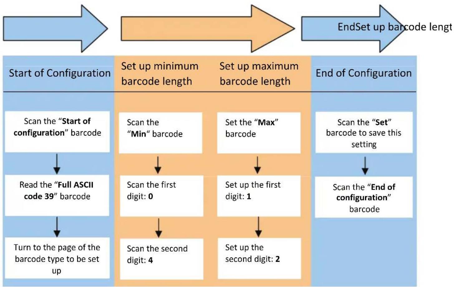
flowchart
graph LR
    A["Start of Configuration"] --> B["Scan the "Start of configuration" barcode"]
    B --> C["Read the "Full ASCII code 39" barcode"]
    C --> D["Turn to the page of the barcode type to be set up"]
    D --> E["Set up minimum barcode length"]
    E --> F["Scan the "Min" barcode"]
    F --> G["Scan the first digit: 0"]
    G --> H["Scan the second digit: 4"]
    H --> I["Set up maximum barcode length"]
    I --> J["Set up the first digit: 1"]
    J --> K["Set up the second digit: 2"]
    K --> L["End of Configuration"]
    L --> M["Scan the "Set" barcode to save this setting"]
    M --> N["Scan the "End of configuration" barcode"]
    N --> O["EndSet up barcode length"]

Use the ASCII table (Appendix 4) to set up barcode length. Be sure to enable the full ASCII code 39 option before you start and read the “Set” label to set your choice into memory.