Breeze 49cc - Rollerblades Bintelli - Free user manual and instructions
Find the device manual for free Breeze 49cc Bintelli in PDF.


User questions about Breeze 49cc Bintelli
0 question about this device. Answer the ones you know or ask your own.
Ask a new question about this device
Download the instructions for your Rollerblades in PDF format for free! Find your manual Breeze 49cc - Bintelli and take your electronic device back in hand. On this page are published all the documents necessary for the use of your device. Breeze 49cc by Bintelli.
USER MANUAL Breeze 49cc Bintelli
natural_image
Exterior view of a green and black SCORCH electric scooter with visible wheels and front wheel (no text or symbols)Contents BINTELLI USER'S MANUAL
Instructions to Users
Precautions ...... 1
Vehicle Identification Number (VIN) and Engine Number... 2
Brief Introduction to the Scooter.... 3
Technical Specifications 6
Instrument Cluster....9
Left control switch 10
Right control switch 11
Ignition switch.... 12
Seat Cushion Lock/ Fuel tank 13
Vehicle Operation 14
Motorcycle Load.... 15
Vehicle load/ tools included.... 16
Operating Instructions
Basic vehicle information.... 17
Kick starting the engine 20
Electric starting the engine 21
Parking the scooter 22
Service and Maintenance
Regular Service and Maintenance 24
New Vehicle Maintenance Procedure (500 mile Service)..25
Level 2 Service and Maintenance 26
Level 3 Service and Maintenance 26
Service and Maintenance for the Carburetor.... 27
Checking and Changing the Engine Oil 28
Service and Maintenance of the Spark Plug.... 29
Service and Maintenance of the Air Filter.... 30
Adjustment of the accelerator handgrip.... 31
Service and Maintenance for the Front Brake 31
Service and Maintenance for the Rear Brake.... 32
Adjustment of the rear brake light 34
Adjustment of the idle speed 34
Service and Maintenance for Front and Rear Tires...... 35
Service and Maintenance for Battery 37
Service and Maintenance for the Fuse.... 38
Service and Maintenance for the Horn.... 38
Storage of the Vehicle 38
Service and Maintenance Interval Table.... 40
Service and Maintenance Interval for Lubricated Parts.... 41
Common Faults and Troubleshooting.... 42
USER'S MANUAL
Instructions to Users
Precautions
Please read the User's Manual before operating the vehicle!
Warning
* Always observe traffic laws and regulations.
* All users' must have a valid driver's license.
* Do not hang any items from the throttle grip as this will cause an unsafe driving condition.
* Please wear a helmet and eye protection at all times.
* Be aware the exhaust and muffler are extremely hot. Do not touch any part of the engine after riding to prevent burns.
Caution
* After unpacking the vehicle from shipping, please check the accessories and various documents delivered according to the packing list.
* Always follow the recommended weight limit. Any additional weight will cause premature wear to the engine and drive train.
* Do not modify any part of the vehicle. Any attempt at modifying the vehicle could lead to a decrease in engine life, reliability and safety.
* This high performance vehicle is designed to be run with premium fuel only (93 octane). Failure to use premium fuel will affect performance and lead to premature engine failure due to detonation and pre-ignition. Any engine damage that has occurred from improper fuel grade is not covered under warranty. It is the user's responsibly to always ensure the correct fuel is used.
Suggestion
* This manual provides important information regarding the vehicle. If ownership transfers, please include this manual.
* All repairs must be completed at an authorized service center. The first 500 mile servicing which includes the valve adjustment must be completed to maintain engine warranty. Failure to follow the servicing schedule outlined in this manual will void the warranty.
Instructions to Users
USER'S MANUAL
Vehicle Identification Number (VIN) and Engine Number
Vehicle Identification Number (VIN) and Engine Number
①Vehicle Identification Number (VIN) is printed on the vertical tube of the frame, behind this plastic cover.
②The product nameplate is riveted on the right lower part of the frame.

natural_image
Empty white rectangle with black border (no text or symbols)③The Engine Number is printed on the lower left part of the crankcase.
Please fill in appropriate numbers for future reference:
VIN: Engine Number:
USER'S MANUAL
Instructions to Users
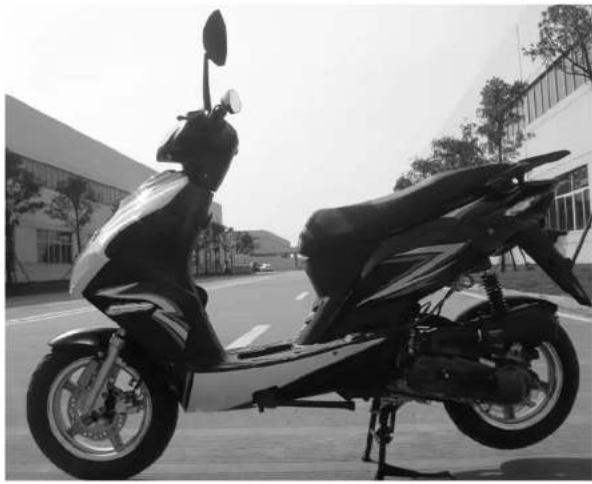
Brief Introduction to the Scooter
- Head Light
- Left front turn light
- Front storage box
- Seat cushion
- Rear carrier
- Disc brake
- Side support
- Main support
- Starting arm
- Air filter
natural_image
Black-and-white photo of a scooter parked on a road, no visible text or symbolsInstructions to Users
USER'S MANUAL
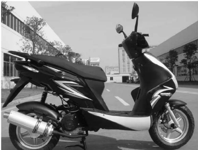
Brief Introduction to the Scooter
natural_image
Black and white photo of a scooter parked outdoors, no visible text or symbols- Tail light
- Rear spoiler
- Helmet hook
- Steering column
- Right front turn signal
- Rear wheel
- Muffler
- Battery Compartment
- Front brake lever
- Front wheel
USER'S MANUAL
Instructions to Users
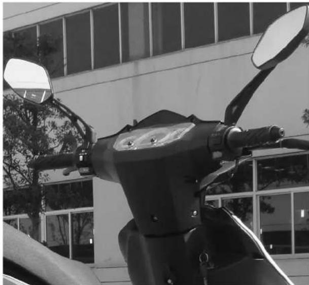
Brief Introduction to the Scooter
- Rearview mirrors
- Left handgrip
- Left control switch
- Instrument cluster
- Ignition switch
- Right control switch
- Throttle grip
natural_image
Black-and-white photo of a motorcycle's front bumper and side mirror mounted on a vehicle, with a building in the background (no visible text or symbols)Instructions to Users
USER'S MANUAL
Technical Specifications
| Sprint | Breeze | Edge | Scorch | Havoc | |
| Engine Type BX139QMB | BN139QMB BX139QMB | BN139QMB BN157QMJ | |||
| Cooling System Air Cooled Air Cooled Air Cooled Air Cooled | Air Cooled | ||||
| Bore x Stroke | 4 stroke | 4 stroke | 4 stroke | 4 stroke | 4 stroke |
| Compression Ratio | 10.4:1 | 10.4:1 | 10.4:1 | 10.4:1 | 9.5:1 |
| Horse Power | 2.4kw/8000r/min | 2.4kw/8000r/min | 2.4kw/8000r/min | 2.4kw/8000r/min | 6.3kw/7500r/min |
| Max Torque N.m/(r/min) | 2.8N.m/6500r/min | 2.8N.m/6500r/min | 2.8N.m/6500r/min | 2.8N.m/6500r/min | 8.8N.m/6000r/min |
| Ignition Type | CD1 | CD1 | CD1 | CD1 | CD1 |
| Starter System | Electric/Kick | Electric/Kick | Electric/Kick | Electric/Kick | Electric/Kick |
| Engine Oil | SJ10W-40 SJ10W-40 SJ10W-40 SJ10W-40 SJ10W-40 | ||||
| Transmission | CVT | CVT | CVT | CVT | CVT |
| Spark Plug Model | NGK CR7HSA NGK CR7HSA NGK CR7HSA NGK CR7HSA | ||||
| Belt Model | Gates 669MM | Gates 669MM | Gates 669MM | Gates 669MM | Gates 835MM |
| Front Suspension Straight Straight Straight Straight Straight | |||||
| Rear Suspension | Single | Single | Single | Single | Double |
| Front Tire Size | 3.50-10 | 3.00-10/3.50-10 | 3.50-10 | 120/70-12 | 130/60-13 |
| Rear Tire Size | 3.50-10 | 3.00-10/3.50-10 | 3.50-10 | 120/70-12 | 130/60-13 |
| Brakes (Front/Rear) | Disc / Drum | Disc / Drum | Disc / Drum | Disc / Drum | Disc / Disc |
| Scooter L x W x H | 67.1" x 25.6"x42.5" | 68.3" x 25.8"x42.9" | 67.7" x 24.8" x43.3" | 73.4" x 27.8" x46.1" | 73.4" x 26.8" x44.1" |
| Seat Height | 28.9" | 29.5" | 29.5" | 32" | 32" |
| Rider Capacity | 2 | 1 | 2 | 2 | 2 |
| Fuel Capacity | 1.4 G | 1.3 G | 1.3 G | 1.6 G | 1.5 G |
USER'S MANUAL
Instructions to Users
| Max Load Capacity 400lb 400lb 400lb 400lb 400lb | |||||
| Scooter Weight 170lb | 172lb 190lb 190lb 225lb | ||||
| Frame Material Steel | Steel Steel Steel Steel | ||||
| Battery | Motobatt 12V,7A | Motobatt 12V,7A | Motobatt 12V,7A | Motobatt 12V,7A | Motobatt 12V,7A |
| Lights | Halogen | Halogen | Halogen | Halogen | Halogen |
| Shipping Dimensions (LxWxII) | 67.3" x 22.8" x44.1" | 67.3" x 22.8" x44.1" | 67.3" x 22.8" x 46.6" | 74.8" x 22.8" x 44.9" | 74.8" x 22.8" x 44.1" |
Instructions to Users
USER'S MANUAL
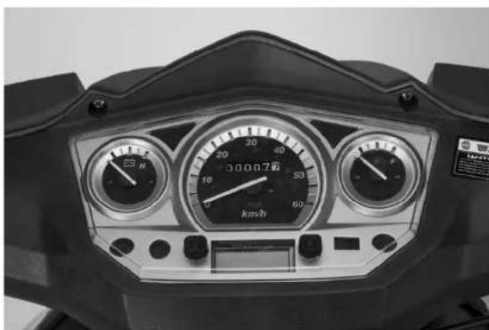
Instrument Cluster
natural_image
Front view of a scooter's front dashboard with speedometer and gauge (no readable text or symbols)- Left turn indicator: When the left turning indicator "←" flashes, the left turn signal is on.
- Tachometer: Indicates the current engine speed in revolutions per minute.
- High beam indicator: When the high beam indicator lamp "☐" is on, it indicates that the "High beam lamp" is on.
- Speedometer: Indicates the current speed of the vehicle
- Odometer: Records the traveled miles of the vehicle
- Fuel gauge: Indicates how much fuel is left in the fuel tank
- Right turn indicator: When the right turning indicator “→” flashes, the right turn signal is on
- Battery Meter (If equipped) Indicates the charge of the battery
USER'S MANUAL
Instructions to Users
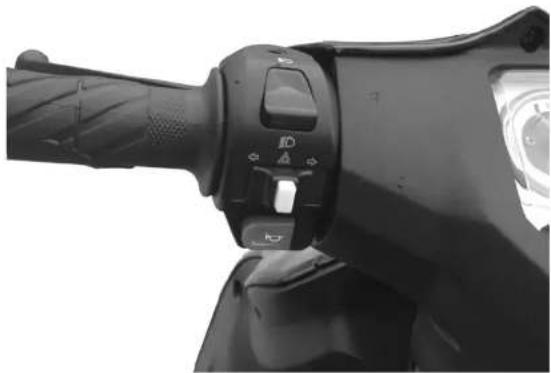
Left Control Switch
natural_image
Close-up of a black motorcycle hand handle and grip mechanism (no visible text or symbols)-
High beam switch: To use the High beam headlight setting, flip the switch up to the “☐” position.
-
Low beam switch: To use the Low beam headlight setting, flip the switch down to “→” position.
-
Horn button: To use the horn, press the button labeled "→".
-
Turn signal switch: When changing direction on the scooter, switch to "→" or "→" to turn left or right. After completing the turn, press the center of the button to turn the signals off.
Instructions to Users
USER'S MANUAL
Right Control Switch
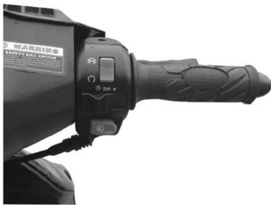
- Head Light switch: (When equipped)
On some models the headlights can be controlled from the right hand switch. To use, turn the Head Light switch to the position "☐", the headlight will turn on with the engine running.
- Electric Start button:
Pressing the “☐” button in combination with holding a brake lever and having the ignition turned on will electrically start the scooter.
- Running light switch: (When equipped)
Turn the Head Light switch to the position "0 0 ≤", and the instrument panel and running lights will come on with the engine running.
- Main light switch: (When equipped)
To turn all the lights of the vehicle off, slide the button to the far right "●" position.
- Throttle Grip:
Turning the grip will increase the speed of the engine which allows the vehicle to move forward. Always turn the grip slowly to provide smooth and safe acceleration.
Caution:
Always use your turn signals and adhere to local traffic laws and regulations
USER'S MANUAL
Instructions to Users
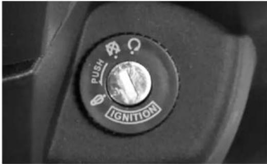
Ignition Switch
Caution
When leaving the vehicle parked, using the "☐" to lock the steering will help deter thefts and prevent the vehicle from being driven.
text_image
PUSH IGNITIONIgnition On:
Turn the ignition key right to the position “()” to turn on the electrical system of the vehicle. The key cannot be removed in this position. While in this position the vehicle can be either electrical started with the push button, or kick started with scooter on the rear kick stand.
Ignition Off:
Turn the ignition key to the position “☒” to switch off the electrical system of the vehicle. In this position the key can be removed. The electrical system of the scooter will remain in the off position.
Steering lock:
Turn the steering left to the outer most position, then turn the ignition key to the position “☐” to lock the steering. Remove the ignition key. In this position the steering will not move. This is recommended when storing the vehicle outside to deter theft. To undo the steering lock, insert the ignition key then rotate to the right while gently moving the steering to disengage the lock.
Instructions to Users
USER'S MANUAL
Seat Cushion Lock
natural_image
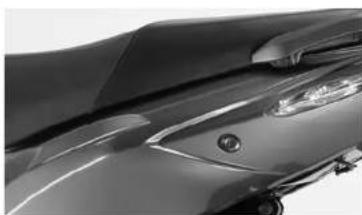
Close-up of a modern car's front wheel and side grille (no visible text or symbols)To open the under seat storage: Insert the ignition key into the seat cushion lock and turn it 90° clockwise to open the seat cushion. *Note* on some scooters like the Breeze, the ignition switch opens the seat. On those models, insert the key into the ignition, and slowly turn to the left until the seat pops open.
Fuel tank
Check page 7 to see your models fuel tank capacity.
natural_image
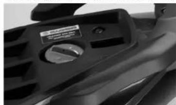
Close-up of a black automotive seat cover with a circular dial indicator (no visible text or symbols)To gain access to the fuel tank, turn the fuel tank cap 90° counter-clockwise and lift up. Always use 93 octane. Be careful when adding fuel to prevent overfilling.
natural_image
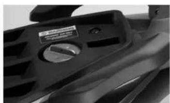
Close-up of a black mechanical component with a circular knob and handle (no visible text or symbols)To close the fuel tank, place the cap on the tank paying careful attention to line up the slots on the gas cap. Turn clockwise to tighten.
USER'S MANUAL
Instructions to Users
natural_image
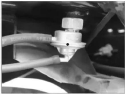
Close-up of a mechanical assembly with hoses and a central component (no visible text or symbols)Fuel petcock: The fuel petcock located in between the gas tank and the carburetor controls the amount of fuel delivered. It uses the vacuum created from engine movement to produce a steady supply of fuel. Some units are mounted directly to the fuel tank while others are attached to the frame.
natural_image
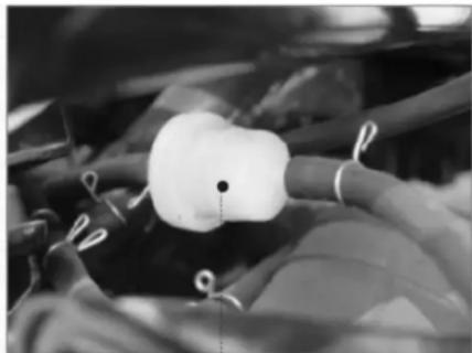
Close-up of a medical device with tubing and a white bulb (no visible text or symbols)Fuel Filter: The fuel filter located inline from the carburetor to the fuel tank acts as a safeguard, keeping small particles and contamination from entering the carburetor. Any blockage of the fuel filter can compromise the fuel system.
Warning
* Be careful not to overfill the fuel tank. Gasoline can damage the finish of the vehicle. Always remove spilled gas from painted surfaces and clean with soap and water.
* Gasoline is flammable. Only fill the vehicle with the engine turned off, and parked in a well ventilated area.
* Do not smoke when filling the vehicle with gasoline. Do not expose gasoline to high heat, sparks, or fire.
Caution
* Only use 93 octane fuel. Failure to use anything but premium fuel can cause engine damage and void the warranty.
Instructions to Users
USER'S MANUAL
Vehicle Operation
All Bintelli scooters use a dry-type automatic centrifugal clutch and belt driven CVT transmission. If there is ever an issue with the transmission belt, variator, or clutch, please have the vehicle serviced at an authorized service center.
natural_image
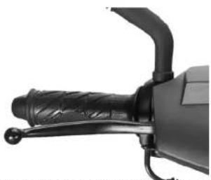
Close-up of a black mechanical lever handle and grip (no visible text or symbols)Front brake handle: When applied, the front brake will engage and slow the vehicle.
natural_image
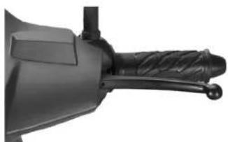
Close-up of a black mechanical tool handle with coiled grip (no visible text or symbols)Rear brake handle: When applied, the rear brake will engage and slow the vehicle.
natural_image
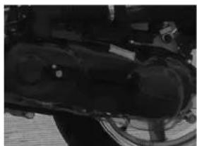
Close-up of a mechanical component with visible internal structure and mounting holes (no text or symbols)Automatic clutch: The belt driven CVT transmission allows for constant acceleration with no need for gear changes. Simply turning the throttle will engage the transmission.
natural_image
Close-up of a dark, textured surface with no visible text or symbolsKick start lever: Allows for manual starting of the vehicle. Manual starting can only be used when the vehicle is on the center kickstand.
USER'S MANUAL
Instructions to Users
Vehicle Load
The maximum load of the vehicle must be strictly observed. Failure to do so will result in an unsafe driving condition, potential engine and/or premature transmission wear.
* Articles in the rear storage box must be securely fixed.(If equipped)
* Never hang items from the front steering.
* The load of the rear carrier must not exceed 10lbs.
* Check page 7 of this manual for your model specific vehicle load limit
Tools included with vehicle
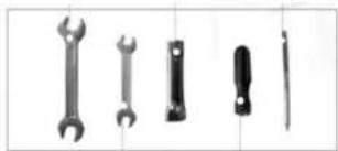
Common service and maintenance tools included with the vehicle:
natural_image
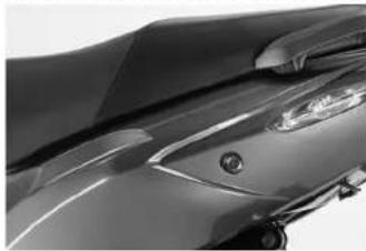
Close-up of a modern car's side profile with visible headlights and grille (no text or symbols)A tool kit under the seat features many of the tools needed to perform routine tasks
Warning
Failure to follow the recommended vehicle load can cause multiple issues with your scooter! Bintelli will not warranty damage or wear that is the result of improper riding!
natural_image
Five different wrench and screwdriver tools arranged horizontally (no text or labels visible)Operating Instructions
USER'S MANUAL
Basic vehicle information
In order to ensure optimal performance of the vehicle, regular service and maintenance must be followed. Always check the vehicle is safe to operate prior to driving.
- Start the engine and allow the vehicle to idle for a few minutes to let the engine warm up.
- Check for any signs of leaks around and underneath the vehicle.
- Check all lights and scooter controls for functionality.
Different levels of maintenance and service will be required at certain odometer readings. Level 2 and 3 servicings include checking and adjusting multiple areas of the scooter in addition to the required oil changes. They are as follows:
500 Mile Servicing: Oil change and valve adjustment **must be performed at authorized service center**
Level 1 Service and Maintenance: Odometer reading 1000-1500 miles.
Level 2 Service and Maintenance: Odometer reading every 3000 miles.
Level 3 Service and Maintenance: Odometer reading every 6000 miles.
Prior to using the vehicle, please perform the following checks to ensure proper safety and performance is met.
natural_image
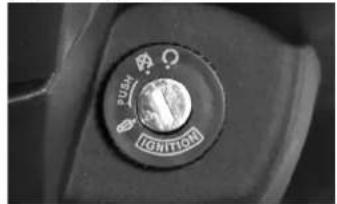
Close-up of a car ignition button with no visible text or symbols on the dial (pure mechanical part)Turn the ignition key to the right and verify the controls are working.
natural_image
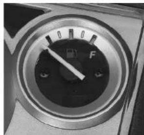
Close-up of a circular industrial control dial with a pointer and valve, no visible text or symbolsCheck the fuel gauge to see if you need to add fuel.
USER'S MANUAL
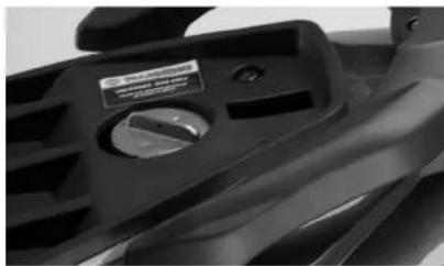
Check that the vehicle has an adequate level of gasoline prior to riding. Verify the gas cap is secured.
natural_image
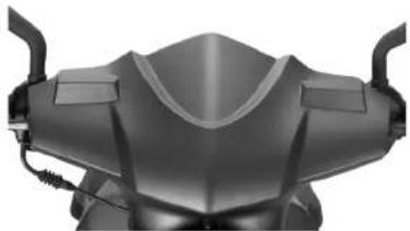
Close-up of a black automotive seat cover with a circular dial indicator (no visible text or symbols)Verify the steering is tight and moves freely. There should be no binding and no play.
natural_image
Close-up of a black motorcycle head with visible front and rear panels (no text or symbols)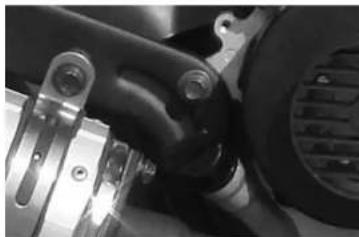
natural_image
Close-up of mechanical components with no visible text or symbolsLevel the vehicle on the rear kick stand and check the oil to verify the oil level is between the upper and lower markings. If not, add oil and recheck. Never drive the scooter with a low oil level, as this will damage the engine.
text_image
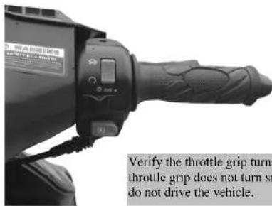
Verify the throttle grip turns throttle grip does not turn sr do not drive the vehicle.Verify the throttle grip turns easily. If the throttle grip does not turn smoothly or binds, do not drive the vehicle.
USER'S MANUAL

natural_image
Close-up of a mechanical component with visible parts and wiring (no text or symbols)Check under the engine for leaks. Any signs of leaking should be addressed prior to riding.
natural_image
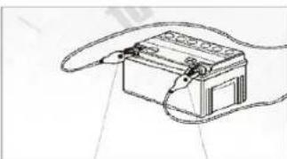
Line drawing of a battery with a coiled cable, no text or symbols presentVerify the connections on the battery terminals are tight and free from damage and corrosion.
natural_image
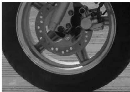
Close-up of a bicycle wheel and brake disc assembly (no visible text or symbols)Check the front tire pressure and inspect the tread. Look for any signs of fluid leaks.
natural_image
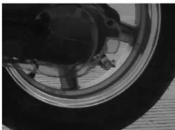
Close-up of a car wheel and tire assembly (no visible text or symbols)Check the rear tire pressure and inspect the tread. Look for any signs of fluid leaks. Verify the rear brake cable engages and disengages smoothly.
Kick Starting the Engine:
The scooter can be kick started by following these steps:
text_image
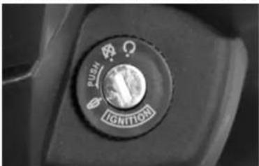
PUSH TIGHTIONTurn the key to the "on" position with the vehicle on the rear kick stand. The vehicle can only be kick started while on the rear kick stand.
text_image
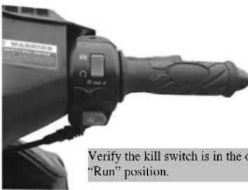
Verify the kill switch is in the o "Run" position.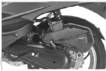
natural_image
Close-up of a motorcycle's internal mechanical components (no visible text or symbols)Pull the kick start lever out. Standing behind the vehicle, use your foot to push down quickly on the lever until the engine turns on. Pause shortly in between kicks to allow the engine to stop spinning.
natural_image
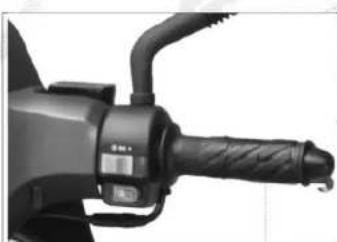
Close-up of a black electric vehicle's hand handle and grip (no visible text or symbols)If the scooter has been sitting for a prolonged period of time turning the throttle 2-3 times will help with cold starts by injecting extra fuel to aid in starting. During extremely cold weather, it is sometimes helpful to slightly open the throttle while kick starting to further aid in quick starting. Always allow the engine to warm up for 2-3 minutes prior to driving.
Operating Instructions
USER'S MANUAL
Electric Starting the Engine:
The duration of each electric start attempt should not exceed 5 seconds. Always wait at least 10 seconds in between starting attempts to prevent the starter from overheating. If 3 startup attempts fail consecutively, the vehicle must be checked.
natural_image
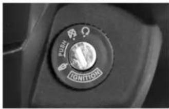
Close-up of a car's ignition button with no visible text or symbols on the dial (pure technical drawing)First, insert the key into the ignition and turn it to the position "○".
natural_image
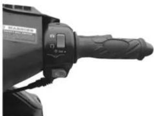
Close-up of a black industrial tool handle with a rotary knob (no visible text or symbols)Verify the kill switch is in the open "run" position. The engine will not run unless the kill switch is in the correct position. Always check this prior to starting.
natural_image
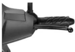
Close-up of a mechanical tool handle with threaded grip and mounting bracket (no visible text or symbols)Hold a brake handle. A safety switch built into the handle will prevent the engine from starting if you fail to do so.
natural_image
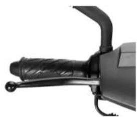
Close-up of a black automotive brake lever handle and grip (no visible text or symbols)Finally, press the electric start button with your right thumb. The engine will start. Remove your thumb from the button once the engine has started. In cold weather, or if the scooter has been sitting, pulling slightly on the throttle will aid in starting.
USER'S MANUAL
Operating Instructions
Parking the Scooter
Always park your vehicle in a safe place.
natural_image
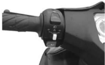
Close-up of a black bicycle brake lever handle and grip (no visible text or symbols)Use your turn signals to warn surrounding vehicles and pedestrians when slowing.
natural_image
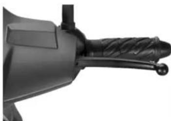
Close-up of a black mechanical tool handle with textured grip and lever (no visible text or symbols)Always use both brakes when slowing the vehicle down.
natural_image
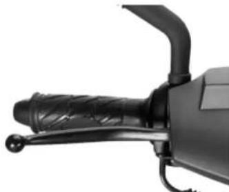
Close-up of a black electric shaver handle and lever mechanism (no text or symbols visible)Release the throttle and use the front brake lever to slow the vehicle. Press both brakes steadily and smoothly to reduce vehicle speed.
natural_image
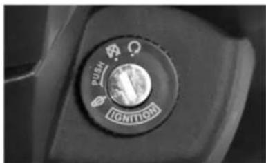
Close-up of a car's ignition button with icons (no readable text or symbols)Once stopped, turn the ignition key left to the off “☒” position to turn off the engine and shut off the electrical system.
Operating Instructions
USER'S MANUAL
natural_image
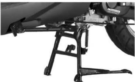
Close-up of a motorcycle's side-mounted lever mechanism (no visible text or symbols)After parking the vehicle, you have 2 choices to use for kickstands. The side kick stand is great for quick use but is not recommended if leaving the vehicle near high foot traffic or unsupervised for a long period of time.
The rear kick stand is far more stable. To place the vehicle on the rear kick stand, place a foot on the kick stand lever and while pressing down shift the weight of the vehicle backwards. The vehicle will reposition itself on the rear kickstand as seen above.
Caution
* When leaving the vehicle parked for an extended amount of time in an unsupervised area, it is recommended to use the steering column lock to deter thefts. Always make sure you remove the ignition key from the vehicle after use.
natural_image
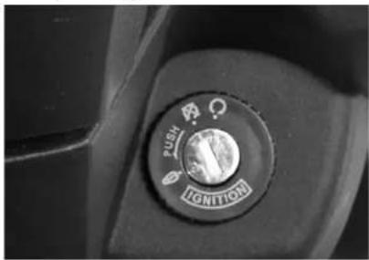
Close-up of a car's ignition button with directional arrows (no text or symbols beyond the label)Turn the ignition lock switch to the position 🔍” to lock the steering column. The vehicle cannot be used in this position
USER'S MANUAL
Service and Maintenance
Regular Service and Maintenance
During normal operation of the vehicle it is possible for hardware to loosen due to vibration. By regularly servicing and maintaining your vehicle the reliability, fuel economy and performance will be maximized. Failure to do so will result in decreased performance, safety, and shorten the service life of the vehicle. Proper regular service and maintenance can prevent issues from occurring, reduce the maintenance costs and keep the vehicle in safe driving condition.
Requirements for Service and Maintenance
The following items should be checked each servicing and prior to riding:
- Keep the engine clean and free from debris. The cooling shroud around the engine should not be blocked off. Verify there is no gas or oil leakage. When the engine starts check for abnormal noise.
- The throttle should turn easily without any binding. Any signs of binding or issues with the throttle should be addressed prior to riding.
-
Verify both front and rear brakes are engaging and adjusted to the proper specificaitons. After releasing each brake lever, the brake system should fully disengage. Any sign of brake issues should be addressed prior to riding. Lubrication of all cables is recommend regularly to prolong service life.
-
The front and rear shock absorbers should be inspected prior to riding. Always check the front and rear tire for correct air pressure and inspect the tread. Do not drive the vehicle with low tire pressure as this can cause the rubber tire to lose its seal and cause injury to the driver.
- Verify there are no loose wires visible.
- Check the oil level prior to riding.
- Verify the battery connections are free of corrosion and tightly secured.
Service and Maintenance in the Run-in Period
During the first 500 miles of driving the new vehicle the speed should not exceed 35mph. Running at constant or full speed for prolonged periods of time must be avoided. It is highly recommended to alternate speeds during the break in period to help the engine wear in properly. After the first 500 mile servicing, the scooter can be driven normally. Proper driving and servicing during the first 500 miles of the vehicle will lead to higher performance and longer lasting engine life.
New Vehicle Maintenance Procedure (500 mile Service)
- Drain and refill oil. Inspect and clean the oil filter screen.
- Drain and refill transmission fluid
- Check the travel I of the front and rear brakes as well as the throttle grip. Adjust them if necessary.
- Inspect all hardware and tighten if necessary.
- Inspect electrical controls. Verify all switches are working.
- Adjust the valve clearance: set the intake valve to 0.003 inches and the exhaust valve to 0.003 inches. **NOTE** Valve clearance can only be checked and adjusted with the engine cold. Allow the vehicle to sit for at least 2 hours after riding to ensure proper adjustment.
- Check turn signal lights, headlight, taillight, and running lights.
Failure to perform the oil change and valve adjustment during the first 500 miles will void the warranty! It is important to have this work done at an authorized Bintelli service center!
Level 1 Service and Maintenance
Level 1 Service and Maintenance should be performed every time after the vehicle runs 1000-1500 miles.:
- Adjust the travel of the front brake to 1/4-3/4 inches, and adjust the rear brake to 3/4-1 inch.
- Adjust the travel of the throttle cable up to a 1/4 inch. Make sure the throttle is closed at idle. Lubricate the throttle grip and the throttle cable.
- Inspect/clean the carburetor, fuel tank, oil filter screen and air filter if necessary.
- Adjust the idle speed of the carburetor. With the vehicle on the center kick stand and the engine running at normal operating temperature, ensure the rear wheel is not spinning at idle.
- Remove and inspect the spark plug. If there is any carbon deposits, clean or replace and adjust the electrode gap spark plug to 0.025 inches.
- Inspect battery terminals. Clean off corrosion if needed and verify tightness of connections.
-
Check all body components for fit. Verify all hardware is secure and in place.
-
Verify the valve clearance: intake valve: 0.003 inches
exhaust valve: 0.003 inches
Level 2 Service and Maintenance
Level 2 Service and Maintenance are additional items that need to be checked at each 3000 mile interval. These items should be checked in addition to the standard Level 1 servicing.
- Check the condition of the transmission clutch. Excessive wear on the clutch pad material indicates replacement is necessary.
- Drain and replace brake fluid.
- Inspect and clean the carburetor, air filter, fuel tank, fuel filter.
- Clean and apply fresh grease to the upper and lower bearings of the steering column.
- Check the front and rear tires for wear. Inspect for signs of damage.
- Clean, inspect and lubricate all cables on the vehicle. Any signs of fraying or damage indicate the need for replacement.
- Drain the transmission fluid and replace. Ins pect and clean all transmission components, checking for wear of the variator and transmission belt. Replace as necessary.
- Verify all electrical controls and switches function normally. Replace any lightbulbs that are not working.
Level 3 Service and Maintenance
Level 3 Service and Maintenance are additional items that need to be checked at each 6000 mile interval. These items should be checked in addition to the standard level 1 and 2 servicing.
- Inspect the frame for damage.
- Inspect the transmission gearbox for damage and wear to the gear teeth.
- Ensure normal operation, of front and rear automatic clutches and the drive system.
- Check whether there is any crack, erosion, spalling or serious stepped wear on each gear tooth of the rear transmission box.
- Ensure normal range of motion and rebound for the front and rear shock absorbers.
- Check entire fuel system. Verify all hoses and connections are secure and no leaks are present.
- Check for damage to the front steering column. Any signs of the front wheel not being properly aligned indicate damage. The steering column must be replaced in the event of any signs of damage.
Service and Maintenance
USER'S MANUAL
Service and Maintenance for the Carburetor
For maximum performance and reliability it is important the carburetor is adjusted properly. Failure to do so will affect starting, idle, as well as the overall vehicles performance.
To ensure maximum performance, please do the following:
- Regularly check all connections and fittings on the carburetor. A poor fit between the intake manifold and carburetor can result in hard starting, poor performance and lower gas milage.
- Check the rubber fuel lines for signs of weathering. Any cracks or deterioration are cause for replacing.
- Start and drive your vehicle often. The longer a vehicle sits the more likely the carburetor is to develop issues due to stale fuel contamination.
- If the vehicle is to be stored for any period of time longer then 2 weeks, the carburetor must be drained to prevent the fuel from contaminating in the bowl of the carburetor. Failure to do so can result in hard starting, poor performance, and result in needing to remove and throughly clean the carburetor.

text_image
DENIChecking and Changing the Engine Oil
natural_image
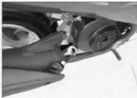
Close-up of a car's front wheel and dashboard components (no visible text or symbols)With the scooter on the center kick stand, unscrew the oil dipstick and wipe clean with a rag. Insert the dipstick, pull out, and check the level and color of the oil. The oil level should always be between the upper and lower oil level markings on the dipstick
natural_image
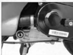
Close-up of a mechanical assembly with no visible text or symbolsFollowing the service intervals in this manual, drain and replace the oil as necessary. The 17mm bolt on the bottom of the engine needs to be removed to drain the oil. Be sure to clean the mesh filter screen before reinstallation.
natural_image
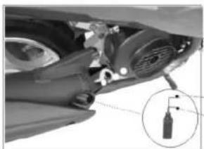
Close-up of a car's head assembly with a magnified inset showing a component detail (no visible text or symbols)After the engine has drained completely, reinstall the mesh screen into the spring. Place the spring into the drain plug and reattach to the engine. Refill the engine with oil.
Upper oil level marking
Lower oil level marking
Caution
Checking and Replacing Engine Oil
To ensure an accurate reading when checking the engine oil, place the vehicle on the center kickstand. Only check the oil level after the engine has been shut off for at least 5 minutes. Be aware the engine and engine oil will be extremely hot if the engine has been running. It is recommended you allow the engine to cool for at least 30 minutes after a long drive before checking.
-Remove oil cap. Note if there is oil on the dipstick. A lack of oil on the dipstick indicates a low oil level.
-Wipe the dipstick clean and insert into engine. Quickly withdraw the dipstick and note the oil level. In between service intervals If there is no oil on the dipstick, it will need to be added.
-Note the color of the oil. Black oil indicates the oil must be drained and replaced.
-To drain the engine oil, loosen the 17mm oil drain plug on the bottom right hand side of the engine, directly underneath the black engine shroud.
-Allow oil to drain completely. Not allowing all the oil to drain will result in residual oil left in the crankcase which will alter the amount needed to fill the engine.
-Inspect oil filter and clean if necessary.
-Reattach oil drain plug with spring and filter installed.
-Fill with 750mL of 10W-40 engine oil through the oil dipstick opening.
-Insert dipstick and withdraw to verify correct oil level.
-Tighten dipstick and inspect for leaks.
Service and Maintenance of the Spark Plug
text_image
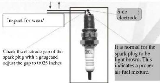
Inspect for wear/ Check the electrode gap of the spark plug with a gaugcand adjust the gap to 0.025 inches Side electrode It is normal for the spark plug to be light brown. This indicates a proper air fuel mixture.Remove the spark plug from the engine. If the color of the insulator skirt of the spark plug is brown it indicates that the carburetor is adjusted properly. Any signs of buildup on the plug should be noted as this could be a sign of an incorrect carburetor adjustment.
Cleaning the Spark Plug
Caution
Inspect the spark plug for carbon buildup. If there are noticeable deposits or wear on the spark plug, replace.
natural_image
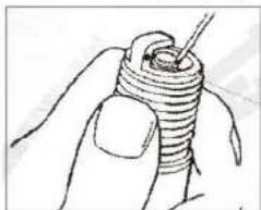
Hand holding a coiled spring or screwdriver (no text or symbols visible)Correct spark plug gap helps fuel economy and performance. Incorrectly gapped spark plugs can lead to hard starting and poor performance. Always replace the spark plug with the original NGK replacement.
natural_image
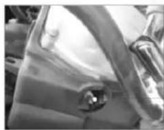
Close-up of a car's side panel showing the wheel and dashboard (no visible text or symbols)When removing and tightening the spark plug, be sure to use the correctly sized socket. Improper removal can result in spark plug damage that can result in costly repairs.
Service and Maintenance for the Air Filter
When the filter element of the air filter is blocked by dust, it may result in increased resistance of the air intake system which leads to a rich gas mixture that can reduce power and increase fuel consumption. It is important the air filter be cleaned on a regular basis.
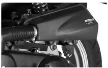
Take off the screws for the air filter cover, and remove the air filter cover. Check whether there is dust and dirt on the sponge foam of the filter element. Remove the air filter.
natural_image
Close-up of a mechanical assembly with hoses and components (no visible text or symbols)Wipe off excessive dust inside the air filter with a clean and dry cloth.
Caution
* It is forbidden to use the following cleaning agents to clean paper filter elements, such as gasoline, low ignition-point solvent, acid, alkaline or organic volatile oil.
Inspect the air filter. During normal operation the air filter will accumulate dust and dirt. Excessive buildup in the air filter indicates the need for replacement. Driving in dusty conditions will lead to more frequent air filter replacements.
Service and Maintenance
USER'S MANUAL
Adjustment of the accelerator handgrip
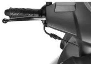
Check whether the free travel of the throttle grip is within the specified range and adjust if necessary. Please follow the following steps to adjust the throttle free travel:
- First, loosen the locking nut.
- Spinning the regulator will extend or shorten the free travel of the throttle.
- When the desired setting is reached, tighten the locking nut and slide the protective covering back over the regulator.
natural_image
Close-up of a mechanical component with threaded handle and wiring (no visible text or symbols)Locking nut
The throttle grip should work smoothly. Any signs of sticking or binding should be addressed prior to riding the vehicle.
Regulator
Service and Maintenance for the Front Brake
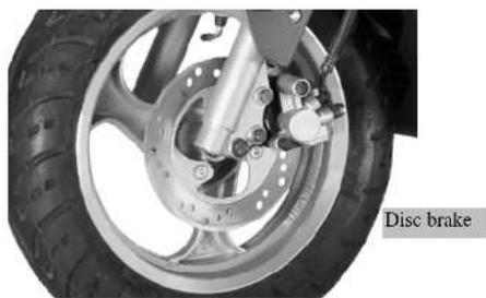
Most models use a front disc brake, which features high heat dissipation and increased performance.
Adjustment of the front disc brake
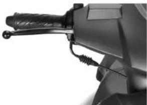
- Place the scooter on the rear kick stand.
- Adjust the regulating nut of the front brake to adjust the free travel of the front braking handgrip to 1/4 -1/2 inch.
natural_image
Close-up of a mechanical tool handle and cable assembly (no visible text or symbols)Adjust the free travel of the front braking handgrip between 14 and 12 inch
USER'S MANUAL
Service and Maintenance
natural_image
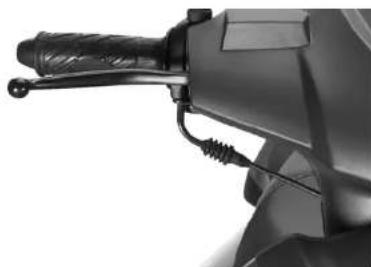
Close-up of a mechanical lever handle and grip (no visible text or symbols)* Check the travel of the brake lever when applied. Excessive travel could indicate worn pads or air in the brake fluid. Either of which need to be addressed prior to riding.
natural_image
Close-up of a disc brake system with visible tire and brake components (no text or symbols)Check for the wear on the front disc rotor. Any signs of warping or irregularites in the surface of the brake rotor can cause vibration, lower braking force, and increase the stopping distance. Replace if needed.
Service and Maintenance
USER'S MANUAL
Service and Maintenance for the Rear Brake
Adjustment of the rear disc brake:
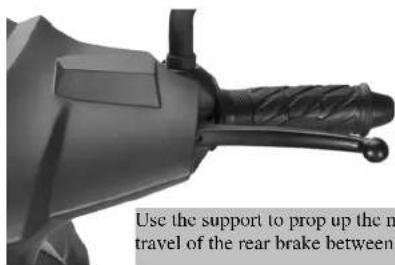
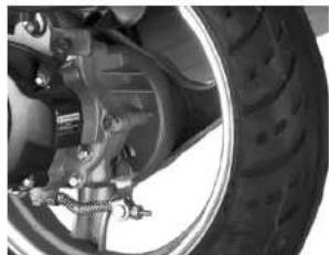
* First, use the support to prop up the rear wheel of the motorcycle and then adjust the free travel of the rear brake.
* Apply the rear brake several times. Each time the brake should release freely without binding or sticking. Rotate the rear wheel assembly to check whether the wheel rotates freely.
**Service Tip** Sometimes mud and dirt can collect around the rear brake cable under transmission. Always keep the cable and fittings clean of dirt and debris. Lubricate the cables often to improve service life.
natural_image
Close-up of a black mechanical component with textured grip and handle, no visible text or symbolsWhen applying the rear brake, ensure the wheel stops spinning within the recommend free travel. On rear brake cable equipped models, turn the brake adjustment fitting at the bottom of the cable clockwise to tighten the cable and reduce free travel. If the adjustment is maxed out, please take your vehicle in to an authorized service center for servicing.
natural_image
Close-up of a car tire and mechanical components, no visible text or symbols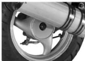
natural_image
Close-up of a car wheel and tire assembly (no visible text or symbols)Use the support to prop up the motorcycle, and adjust the free travel of the rear brake between 14 - 12 inch.
Adjustment of the rear brake light
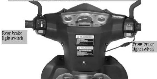
* It is important to always check the vehicles lights are properly functioning prior to using the vehicle. The brake light can be inspected with the ignition turned to the on position, and the left brake handle pressed. * When applying the front and rear brakes, each side should turn the rear brake light on when pressed individually. Switches mounted to the inside of the brake handles cause the brake light to turn on when pressed.
In order to gain access to the brake switches the left and right side controls must be removed as well as the brake handles. This can be performed at your local authorized service center.
text_image
Rear brake light switch FR4.R01380 FR4.R01380 FR4.R01380 FR4.R01380 FR4.R01380 FR4.R01380 FR4.R01380 FR4.R01380 FR4.R01380 FR4.R01380 FR4.R01380 FR4.R01380Adjustment of the idle speed
If the vehicle stalls out during normal operation due to the engine speed being too low, the idle speed of the can be adjusted as outlined in the following steps:
* Before adjusting the idle, make sure the engine has reached normal operating temperature.( typically 5-10 minutes of driving )
* Place vehicle on the center kickstand.
* With the engine running, adjust the idle speed to the specified value.
* If the engine dies
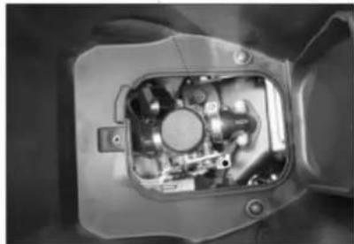
Adjust the idle speed screw here. Turning clockwise will raise the idle; counter clockwise will lower the idle.
natural_image
Interior view of a mechanical device showing internal components and mounting holes (no visible text or symbols)Service and Maintenance
USER'S MANUAL
Service and Maintenance for Front and Rear Tires
Prior to riding always inspect the tires. Make sure the front and rear tire are filled to their recommend pressure. Proper tire inflation increases riding comfort and stability of the driving of vehicle while prolonging the service life of the tires.
| Tire Pressure | Front wheel | 30psi |
| Rear wheel | 32psi |
natural_image
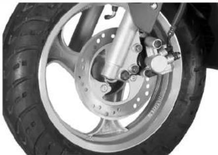
Close-up of a motorcycle wheel and tire assembly (no visible text or symbols)Check the air pressure of the tire and visually inspect the rubber tire and rim for excessive wear or defects. If there are any issues, the tire should be replaced at a local authorized service center.
Removal and Installation of Front Wheel
* With the engine off, place the vehicle on the center kickstand.
* Remove the nut off the front wheel bolt. Slide the bolt out while making sure to retain all hardware including wheel spacers, and speedometer sending unit.
Caution:
* Do not use the front brake with the wheel removed.
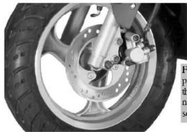
* Always retorque the front wheel nut to 80ft.lbs.
* Check fluid level and top off if needed. Verify the wheel spins freely with no brake drag.
natural_image
Close-up of a motorcycle wheel and brake assembly (no visible text or symbols)Failure to properly torque the front wheel nut can lead to serious injury!
USER'S MANUAL
Service and Maintenance
Removal and Installation of the Rear Wheel
* Verify the engine is off.
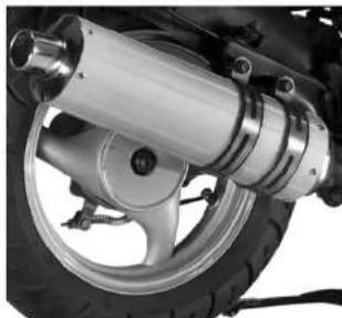
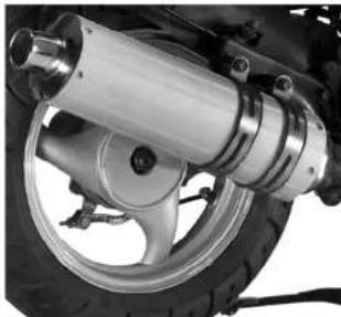
* Place vehicle on center kick stand and remove muffler.
* Loosen the rear wheel nut, and remove the rear wheel.
Installation precautions:
* Torque the rear wheel nut to 80ft.lbs. and reinstall muffer.
* Verify the rear brake is adjusted properly.
Muffler
natural_image
Close-up of a motorcycle wheel assembly with metallic components (no visible text or symbols)Rear Wheel Nut
If the tread depth in the middle of the tire reaches the following limits the tire must be replaced immediately.
| Minimum limit of tread depth | Front wheel | 5/64 inch |
| Rear wheel | 5/64 inch |
natural_image
Close-up of a motorcycle wheel assembly with metallic components and a tire (no visible text or symbols)Check the tread wear depth of the tire and inspect for damage. If any abnormality is found, the tire must be replaced immediately.
Caution
* Low tire pressure will increase the rolling resistance of vehicle, increase fuel consumption and wear the tire prematurely. In more severe cases it can lead to blow outs. Always check tire pressure prior to riding.
- Excessive tire pressure will cause uneven tire wear, increase the risk for blow outs, and decrease vehicle stability.
Service and Maintenance
USER'S MANUAL
Service and Maintenance for Battery
All Bintelli scooters come standard with a MotoBatt Quadflex Sealed Maintenance Free AGM Battery. These high performance batteries offer more cold cranking amps and higher capacities then standard scooter batteries. In order to maintain and prolong the life of your battery, please maintain the battery as follows:
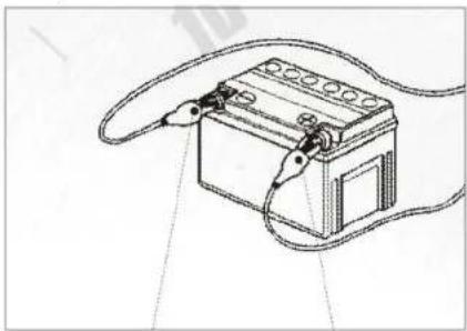
- Keep terminals clean and free from corrosion.
- Ensure battery terminals and all connections are tight. Loose wires can lead to a loss of the electric start.
- Alwa ys remove the battery from the scooter and place onto a trickle charger if the vehicle is not going to be used for more than a 2 week period. Failure to maintain the charge of the battery can lead to poor service life.
- MotoBatt batteries are sealed unit s, never remove any part of the battery to replace fluids.
natural_image
Line drawing of a battery with wires and connectors (no text or symbols)Ensure the battery terminals are clean and tightened properly. Any signs of corrosion need to be cleaned promptly to prevent damage to the battery and cables.
text_image
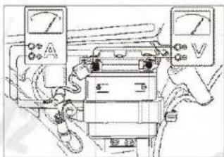
Diagram showing hands operating a device with labeled terminals A and V, and a close-up of the switch.When checking the voltage of the battery, a reading of less than 12 volts indicates the need for the battery to be charged. You can also place the battery under a load test to verify the strength.
natural_image
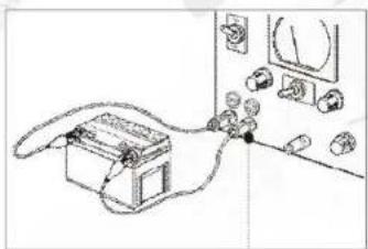
Line drawing of a telephone handset connected to a wall-mounted device (no text or symbols)Weak batteries will be unable to start the scooter. Place the battery on a 12volt trickle charger to maintain and prolong the service life.
Service and Maintenance for the Fuse
The fuse is connected in series to the battery. If there is a sudden power surge or issue within the electrical system, the fuse will automatically break to protect the battery and other electrical components. Bintelli recommends using the OEM 15amp fuse.

natural_image
Close-up of an electronic device showing internal components and wiring (no visible text or symbols)If the entire electrical system of the scooter is not functioning, check the fuse first. A blown fuse will cause all electrical components including the electrical start to stop functioning.
Caution
* A blown fuse can signify a problem with the battery, charging system, or wiring harness. Always have your vehicle inspected at an authorized Bintelli service center in the event of a blown fuse.
Service and Maintenance for the Horn
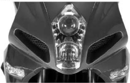
Over time the horn may need to be adjusted due to road vibrations. By removing the front panel you can gain access to the horn and the adjustment screw.
natural_image
Close-up of a black motorcycle's head and grille (no visible text or symbols)If the horn sound becomes weak or no longer works, remove the front panel. Use a multi-meter to measure the output voltage of the horn circuit. If the horn is receiving 12volts with the ignition turned on, use the horn regulating screw to adjust the sound volume of the horn to the desired level.
Service and Maintenance
USER'S MANUAL
Storage of the Vehicle
Long-time storage:
For vehicles that will be parked for longer then a month, the following items need to be performed.
* Drain all fuel from carburetor and fuel tank.
* Remove spark plug. Pour a tablespoon of clean engine oil into the cylinder. Using the kick start, turn the engine over 10-20 times to evenly distribute oil inside the cylinder.
* Remove the battery and place on a trickle charger.
* Wash the vehicle and wipe dry with a soft cloth. Wax the painted surfaces, and apply a film of anti-rust oil to the chrome surfaces.
* Increase the tire pressure to the normal specification if low.
* Cover the vehicle and store it in a well-ventilated, waterproof area.
When removing from storage:
* Clean the vehicle. Replace the engine oil if the vehicle has been sitting for more than 4 months.
* Check the battery. Reinstall and verify all connections are secure.
* Refill fuel tank.
* Perform a visual inspection and check for leaks.
Caution
Failure to keep the battery on a trickle charger during prolonged periods of storage will result in electric start problems.
USER'S MANUAL
Service and Maintenance
Service and Maintenance Interval Table
Regular Service and Maintenance is generally based on the reading of the odometer. When the motorcycle is working under bad conditions or under load operation for a long time, the service and maintenance interval should be appropriately shortened.
| Times of service and maintenanceItems of service and maintenance | Item | Odometer | |||||
| Interval | 500 Miles | 1500 Miles | 3000 Miles | 4500 Miles | Remarks | ||
| Fuel system | C | C | C | C | Items marked “※※” can only be performed by an authorized Bintelli service center. When driving in a highly dusty area the service and maintenance interval should be appropriately shortened. | ||
| Fuel filter | C | C | C | C | |||
| Throttle cable | A | A/C | A/C | A/C | |||
| ※※ | Carburetor | C | C | C | C | ||
| Air filter | C | C | C | C | |||
| Spark plug gap | A/C | A/C | A/C | A/C | |||
| ※※ | Valve lash | A | I | I | I | ||
| Engine oil | R | R | R | R | |||
| Oil Filter Screen | C | C | C | C | |||
| ※※ | Timing chain | I | A | A | A | ||
| Carburetor idling | A | A | A | A | |||
| ※※ | Transmission Belt | - | A | R | R | ||
| Battery | B | B | B | B | |||
| Brake shoe | I | A | A | R | |||
| ※※ | Braking system | A | A | A | R | ||
| Brake light switch | A | A | A | A | |||
| Lighting system | I | I | I | I | |||
| ※※ | Clutch | I | I | I | I | ||
| ※※ | Shock absorber | I | I | A | A | ||
| Nuts and bolts | G | G | G | G | |||
| Front and rear tire hardware | I | I | I | I | |||
| Throttle grip | I | A | A | R | |||
| A-Adjustment C-Cleaning I-Inspection R-Replacement G-Tightening B-Battery Charging | |||||||
Service and Maintenance
USER'S MANUAL
Service and Maintenance Interval for Lubricated Parts
| Name Model | Odometer reading | ||||||||
| Miles | 1000 | 2000 | 4000 | 8500 | 10500 | 15000 | 20000 | ||
| Engine Oil | SAE 10W-40 | - | R | R | R | R | R | R | R |
| Brake Cables | Multipurpose lithium-based lubricating grease) | - - R | R R R R R | ||||||
| Brake Fluid | DOT3 or DOT4 | - | R | - | |||||
| Lubricating oil for front shock absorber | Lubricating grease for shock absorber | - I I I | T I I I | ||||||
| Tachometer gear | Multipurpose lithium-based lubricating grease | - I R I R I | |||||||
| Steering gear | Multipurpose lithium-based lubricating grease | - | I - R - | ||||||
| Bearings for front and rear wheels | Multipurpose lithium-based lubricating grease | - I R I R R | |||||||
| Rear braking swing arm | Multipurpose lithium-based lubricating grease | - | I - I - | ||||||
| I-Inspection R-Replacement T-Addition | |||||||||
Common Faults and Troubleshooting
| Fault system | Fault | Causes | Troubleshooting |
| Fuel system | The engine is unable to be started. | Fuel not entering the carburetor;Fuel not flowing from fuel tank;The vacuum line fitting leaks;The fuel line is blocked;The vacuum hose is blocked. | Check fuel lines for blockageCheck the fuel petcockReplace the vacuum line fittingReplace fuel lineReplace the vacuum hose |
| The vehicle is difficult to start or the fuel is excessively consumed. | The carburetor is blocked;Incorrect air/fuel mixture;The carburetor leaks;The fuel filter is blocked;The throttle of the carburetor is worn;The fuel is bad;The air vent of the fuel tank is blocked;Low fuel | Clean or replace the carburetorReadjust the mixing ratio and concentration of the carburetor.Clean the carburetor or replace the carburetor floaterClean the fuel filterReplace the throttleReplace the fuel.Remove blockage in air vent of the fuel tankAdd fuel to the fuel tank | |
| Air intake/exhaust system | The vehicle is hard to start | The Air filter element is blocked;The air filter leaks;The air filter has too much dust;The air filter housing leaks;Excessive carbon buildupThe exhaust port leaks;The muffler is blocked. | Clean the air filter elementReplace the air filterClean the air filter element.Repair or change the air filter housing.Clean the carbon buildupReplace cylinder headReplace muffler |
Service and Maintenance
USER'S MANUAL
Common Faults and Troubleshooting
| Fault system | Fault | Causes | Troubleshooting |
| EPA Device | Emitted pollutants exceed applicable standards | Too much carbon is built up at the secondary air intake port.The air pump is blocked or damaged.The air pump filter is blocked or damaged.The intake rubber hose is leaking.The clamp is loose or damaged | Clean the carbon buildup at the secondary air intake port.Replace the air pump.Replace the air pump filter.Replace the intake rubber hose.Replace the clamp. |
| Ignition system Weak or no spark | Excessive carbon buildup on the spark plug.The spark plug is not gapped properlyThe spark plug is damaged | Clean the carbon buildup and dirt on the spark plug .Adjust the gapReplace the spark plug | |
| Short-circuit of the ignition coilC.D.I is faulty. | Replace the ignition coilReplace C.D.I | ||
| The stator is faulty.The connection of the ignition system is loose. | Replace the statorCheck each connection. | ||
| Engine Mechanical | The engine will not idle | The cylinder head is leakingValves are not adjusted properly .Excessive blowby from piston rings | Replace the cylinder headAdjust the valves to specified clearance.Replace piston rings/hone or replace cylinder |
Common Faults and Troubleshooting
| Fault system | Fault | Causes | Troubleshooting |
| Engine Mechanical | Compression ratio is too high | There is too much carbon buildup in the combustion chamber and on the top of the piston. | Clean the carbon buildup in the combustion chamber and on the top of the piston. |
| Excessive noise from engine. | Valves are incorrectly adjusted.The air valve is brokenInternal engine damage from oil starvation | Readjust the valve clearanceReplace the air valveReplace damaged engine internals | |
| The cylinder compression is low | Damage to cylinder, rings, valves, piston possible | Replace damaged parts | |
| Excessive smoke from muffler | Worn/ damaged piston ringsOil leaking past valve seals.Wear on piston and piston rings | Replace the piston, rings, cylinderReplace valve sealsReplace the piston, rings/ cylinder | |
| The cylinder head leaks. | Valves not adjusted at 500 mile servicing | Cylinder head needs to be replaced | |
| Front Wheel | The front wheel vibrates | The front shock absorber is faultyThe triple tree is bent from a crashThe front wheel is damagedObject in tireThe front wheel bearings are worn out or damaged. | Replace the front shock absorberReplace triple treeReplace front wheelReplace tireReplace the front wheel bearings. |
| The front wheel has play in it | The front wheel is damagedThe front wheel nut is looseThe tire pressure is too low.The front wheel bolt is loose. | Replace the front wheelTorque the front wheel nut to the proper specification Increase the tire pressure.Torque the front wheel nut to the proper specification |
Service and Maintenance
USER'S MANUAL
Common Faults and Troubleshooting
| Fault system | Fault | Causes | Troubleshooting |
| Rear Wheel | The rear wheel vibrates. | The rear wheel is damaged.The tire pressure is too low.The rear wheel nut is loose. | Replace the rear wheel.Increase the tire pressure.Torque the rear wheel nut to the proper specification |
| Suspension system | The shock absorber no longer rebounds | The spring of the shock absorber is worn out | Replace the spring of the shock absorber |
| The shock absorber is improperly adjusted. | Re-adjust the shock absorber | ||
| Brakes Poor braking performance | The master cylinder has air in itThe front brake pads are wornThe rear disc pads are wornContaminated or old brake fluid | Bleed the brake linesReplace front brake pads/ bleed linesReplace rear brakes/ adjust brake cableFlush and bleed brake lines | |
| Lights | The head light will not turn on | The head light bulb is burnt out.The headlight switch is faulty.The connecting plug is loose.The fuse is burnt outThe battery is dead | Replace the head light bulb.Inspect headlight switch wires/ replaceCheck the plug connectorReplace the fuse.Charge the battery |
| Stator issue | Check stator connections/ replace | ||