GV-BL320D - Security Camera Geovision - Free user manual and instructions
Find the device manual for free GV-BL320D Geovision in PDF.


User questions about GV-BL320D Geovision
0 question about this device. Answer the ones you know or ask your own.
Ask a new question about this device
Download the instructions for your Security Camera in PDF format for free! Find your manual GV-BL320D - Geovision and take your electronic device back in hand. On this page are published all the documents necessary for the use of your device. GV-BL320D by Geovision.
USER MANUAL GV-BL320D Geovision
natural_image
Three white GeoVision security cameras against a blue background, no visible text or symbols on the devices themselves.- Bullet Camera
- Ultra Bullet Camera
• Target Bullet Camera

GeoVision
© 2015 GeoVision, Inc. All rights reserved.
Under the copyright laws, this manual may not be copied, in whole or in part, without the written consent of GeoVision.
Every effort has been made to ensure that the information in this manual is accurate. GeoVision, Inc. makes no expressed or implied warranty of any kind and assumes no responsibility for errors or omissions. No liability is assumed for incidental or consequential damages arising from the use of the information or products contained herein. Features and specifications are subject to change without notice. Note: no memory card slot or local storage function for Argentina.
GeoVision, Inc.
9F, No. 246, Sec. 1, Neihu Rd.,
Neihu District, Taipei, Taiwan
Trademarks used in this manual: GeoVision, the GeoVision logo and GV series products are trademarks of GeoVision, Inc. Windows and Windows XP are registered trademarks of Microsoft Corporation.
September 2015
Contents
Options 3
Note for Adjusting Focus and Zoom....4
Note for Installing Camera Outdoor....5
Note for Closing the Bullet Camera Cover......6
Note for Recording ....7
Note for Waterproofing Failures....8
Chapter 1 Bullet Camera (Part I)....9
1.1 Packing List....11
1.2 Features....12
1.3 Overview....15
1.4 Installation....16
1.4.1 Connecting the Camera ....18
1.4.2 Adjusting the Angles .....23
1.4.3 Adjusting Lens and Inserting a Memory Card.....27
1.4.4 Installing the Sun-Shield Cover.... 31
1.5 Loading Factory Default....32
Chapter 2 Bullet Camera (Part II)....33
2.1 Packing List....35
2.2 Features....36
2.3 Overview ....38
2.4 Installation....40
2.5 Connecting the Camera....47
Chapter 3 Ultra Bullet Camera....49
3.1 Packing List....51
3.2 Features....52
3.3 Overview ....54
3.4 Installation....56
3.4.1 Waterproofing the Cable 61
3.4.2 Connecting the Camera 63
3.5 Loading Factory Default....66
Chapter 4 Target Bullet Camera....67
4.1 Packing List....68
4.2 Features....69
4.3 Overview 70
4.4 Installation....72
4.5 Connecting the Camera....75
4.5.1 Wire Definition 75
4.5.2 Power Connection....76
4.6 Loading Factory Default....77
Options
Optional devices can expand your camera's capabilities and versatility. Contact your dealer for more information.
| Device Description | |
| Power Adapter | The power adapter is available for all Bullet Camera, Ultra Bullet Camera (except GV-BL2511-E / 5311-E), and Target Bullet Camera. Contact your sales representative for the countries and areas supported. |
| GV-PA191 PoE Adapter | The GV-PA191 PoE adapter is designed to provide power and network connection to the cameras over a single Ethernet cable. |
| GV-Relay V2 | The GV-Relay V2 is designed to expand the voltage load of GV IP devices. It provides 4 relay outputs, and each can be set as normally open (NO) or normally closed (NC) independently as per your requirement. |
| GV-POE Switch | The GV-POE Switch is designed to provide power along with network connection for IP devices. The GV-POE Switch is available in various models with different numbers and types of ports. |
| GV-Mount Accessories | The GV-Mount Accessories provide a comprehensive lineup of accessories for installation on ceiling, wall corner and pole. For details, see GV-Mount Accessories Installation Guide on the Software DVD. |
Note for Adjusting Focus and Zoom
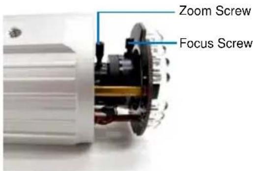
When adjusting the Focus and Zoom Screws on Bullet Camera, do not over tighten the Focus and Zoom screws. The screws only need to be as tight as your finger can do it. It is not necessary to use any tools to get them tighter. Doing so can damage the structure of lens.
For example,
text_image
Zoom Screw Focus ScrewBullet Camera
The maximum torque value for all the zoom and focus screws is 0.049 N.m
Note for Installing Camera Outdoor
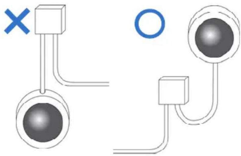
When installing the cameras outdoor, be sure that:
- The camera is set up above the junction box to prevent water from entering the camera along the cables.
natural_image
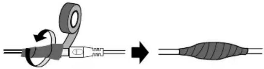
Diagram showing two connected components with a cross mark and a circle, no text or symbols present- Any PoE, power, audio and I/O cables are waterproofed using waterproof silicon rubber or the like.
natural_image
Diagram showing a mechanical assembly with rotating components and a final elongated body (no text or symbols)- The silica gel bag loses its effectiveness when the dry camera is opened. To prevent the lens from fogging up, replace the silica gel bag every time you open the camera, and conceal the gel bag in camera within 2 minutes of exposing to open air.
Note for Closing the Bullet Camera Cover
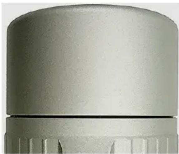
To ensure that the camera performs its full capacity against water and dust, tightly close and lock the camera cover as indicated below.
natural_image
Close-up of a metallic cylindrical component with fluted ends and a flat top (no text or symbols visible)Note for Recording
1 By default, the images are recorded to the memory card inserted in the GV-IP Camera H.264 (except GV-IR Arctic Box Camera and Target Series, which are not equipped with a memory card slot).
Make sure the Write recording data into local storage option (see 4.1.1 Video Settings, GV-IPCam H.264 Firmware Manual) is enabled. If this option is disabled, the camera will stop recording to the memory card while the live view is accessed through Web browsers or other applications.
2 Mind the following when using a memory card for recording:
- Recorded data on the memory card can be damaged or lost if the data are accessed while the camera is under physical shock, power interruption, memory card detachment or when the memory card reaches the end of its lifespan. No guarantee is provided for such causes.
- The stored data can be lost if the memory card is not accessed for a long period of time. Back up your data periodically if you seldom access the memory card.
- Memory cards are expendable and their durability varies according to the conditions of the installed site and how they are used. Back up your data regularly and replace the memory card annually.
- Replace the memory card when its read/write speed is lower than 6 MB/s or when the memory card is frequently undetected by the camera.
3 It is recommended to use memory cards of the following setting and specifications:
- Apply a battery backup (UPS) to avoid power outage.
- Use Micro SD card of MLC NAND flash, Class 10 for better performance.
Note for Waterproofing Failures
To avoid waterproofing failures, do not open the screw on the camera body.
- The screw on Ultra Bullet Camera
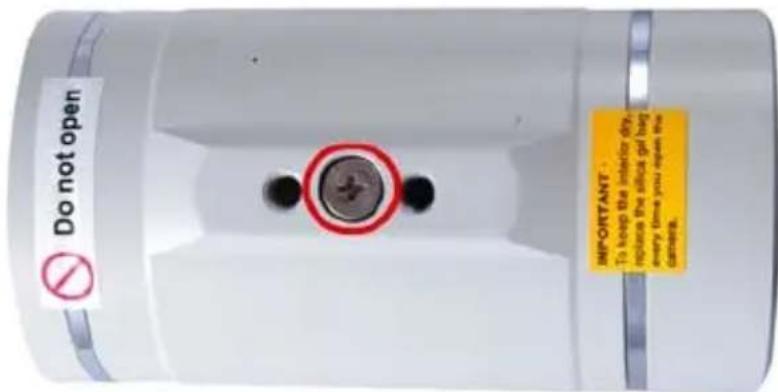
text_image
Do not open IMPORTANT: To keep the interior dry, replace the silicon gel bag every time you open the diameter.- The screw on Target Bullet Camera
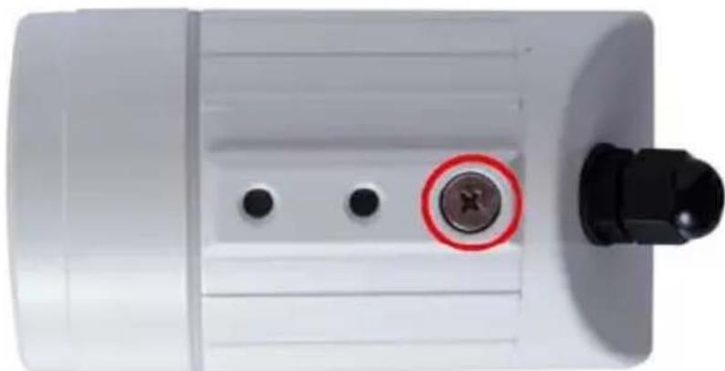
natural_image
Close-up of a white cylindrical device with three circular holes and a black connector (no visible text or symbols)Chapter 1 Bullet Camera (Part I)
The Bullet Cameras are specifically designed for outdoors and are weatherproof (IP66 or IP67). They are equipped with IR LEDs for infrared illumination in night vision applications. The models described in this chapter use auto iris, which allows for automatic control of exposure.
The WDR Pro models enhance the image by processing contrasting intensity of light. The super low lux models can produce color live view in near darkness. The motorized varifocal lens models allow the user to adjust the focus and zoom through the Web interface.
| Model No. | Specifications | Description | |
| GV-BL120D | 1.3 MP, H.264, Varifocal lensMP, H.264, | Low LuxAuto Iris, f: 3 ~ 9 mm, F/1.2, 1/2.7”ø 14 mm LensMountWDR Pro | |
| GV-BL130D | 1.3 | ||
| GV-BL220D | 2 | ||
| GV-BL320D | 3 | ||
| GV-BL1500 | 1.3 MP, H.264, Super Low Lux | ||
| GV-BL2400 2 | |||
| GV-BL2500 | 2 MP, H.264, Super Low Lux | ||
| GV-BL3400 | 3 MP, H.264, WDR Pro | ||
| GV-BL1210 | Motorized varifocal lens | Auto Iris,f: 3 ~ 9 mm,F/1.2, 1/2.7”ø 14 mm LensMount | 1.3 MP, H.264, Low Lux,3X Optical Zoom |
| GV-BL2410 | 2 MP, H.264, WDR Pro,3X Optical Zoom | ||
| GV-BL3410 | 3 MP, H.264, WDR Pro,3X Optical Zoom | ||
| GV-BL5310 | Auto Iris,f: 4.5 ~ 9 mm,F/1.2, 1/2.7”ø 14 mm LensMount | 5 MP, H.264, 2X Optical Zoom | |
1.1 Packing List
- Bullet Camera
- Self Tapping Screw x 3
- Plastic Screw Anchor x 3
- Torx Wrench x 2
- Sun-Shield Cover Kit (Sun-Shield Cover, Philips Head Screw x 2, Plastic Screw Spacer x 2 and Hexagon Screw x 2)
- Silica Gel Bag x 2
• 2-Pin Terminal Block - Power Adapter
• GV-IPCAM H.264 Software DVD
• GV-NVR Software DVD - Warranty Card
Note: The power adapter can be excluded upon request.
1.2 Features
- Image sensor
| Camera Model Image Sensor | |
| GV-BL120D / 1210 1/3” progressive scan low lux CMOS | |
| GV-BL1500 / 1510 | 1/3” progressive scan super low lux CMOS |
| GV-BL130D / 220D / 320D GV-BL5310 | 1/2.5” progressive scan CMOS |
| GV-BL2400 / 2410 GV-BL3400 / 3410 | 1/3.2” progressive scan CMOS |
| GV-BL2500 / 2510 | 1/2.8” progressive scan super low lux CMOS |
• Dual streams from H.264 or MJPEG
- Frame rate
| Camera Model Frame Rate | |
| GV-BL120D / 130D | 30 fps at 1280 x 1024 |
| GV-BL1210 | |
| GV-BL1500 / 1510 | |
| GV-BL220D / 2400 / 2410 | 30 fps at 1920 x 1080 |
| GV-BL2500 / 2510 | |
| GV-BL320D/ 3400 / 3410 20 | fps at 2048 x 1536 |
| GV-BL5310 10 fps at 2560 x | 1920 |
• Day and night function (with removable IR-cut filter)
- Megapixel lens
- Motorized varifocal lens for remote focus/zoom adjustment (GV-BL1210 / 1510 / 2410 / 2510 / 3410 / 5310 only)
- Wide Dynamic Range Pro (GV-BL2400 / 2410 / 3400 / 3410 only)
- Ingress protection
(IP66 for GV-BL120D / 130D / 220D / 320D)
(IP67 for GV-BL1500 / 2400 / 2500 / 3400 and GV-BL1210 / 1510 / 2410 / 2510 / 3410 / 5310)
- Vandal resistance (IK10 for metal casing for all models except GV-BL120D / 130D / 220D / 320D)
- Two-way audio
• One sensor input and alarm output - Micro SD card slot (SD/SDHC) for local storage
- NAS recording
- Recording assigned by GV-Edge Recording Manager (Windows & Mac)
- Cable-concealed bracket preventing cable from being cut
• DC 12V / AC 24V / PoE (IEEE 802.3af) - Intelligent IR
• Maximum IR distance
| Camera Model Maximum IR Distance | |
| GV-BL120D / 130D / 220D / 320D 15 | m (50 ft) |
| GV-BL1210 / 5310 40 m (131 ft) | |
| GV-BL2400 / 2410 | 50 m (164 ft) |
| GV-BL2500 / 2510 | |
| GV-BL3400 / 3410 | |
| GV-BL1500 / 1510 70 m (230 ft) | |
- 3D noise reduction (GV-BL1500 / 1510 / 2500 / 2510 only))
- 2D noise reduction (for all models except super low lux models)
- Defog
- Motion detection
- Tampering alarm
- Visual automation
- Text overlay
- Privacy mask
- IP address filtering
• Smart Phone and 3GPP support
• 31 languages on Web interface
• ONVIF (Profile S) conformant
1.3 Overview
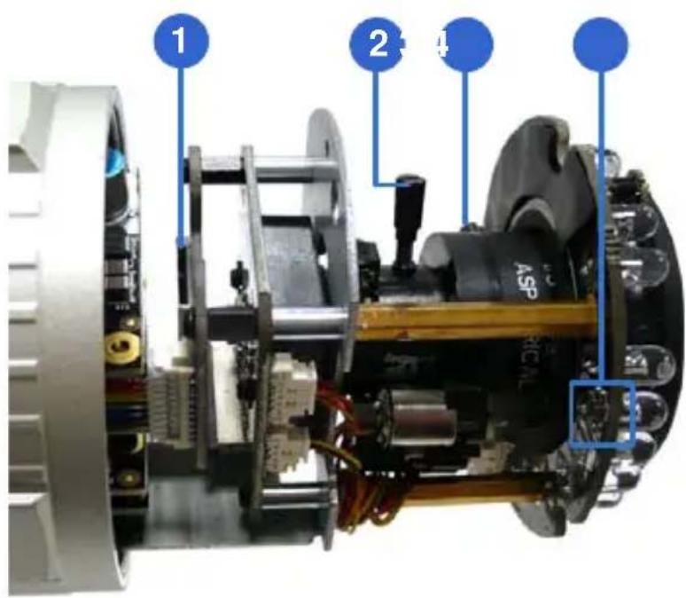
text_image
1 2 4 ASP MICNLFigure 1-1
| No. | Name Description | |
| 1 | Memory Card Slot | Receives a micro SD card (SD/SDHC, version 2.0 only, Class 10). |
| 2 | Zoom Screw Holds the zoom lens in place. | |
| 3 | Focus Screw Holds the focus lens in place | |
| 4 | Default Button | Resets all configurations to factory default. For details, see 1.5 Loading Factory Default. |
1.4 Installation
These instructions describe the basic installation of the Bullet Camera.
- Slide the cable clamp to the camera base.
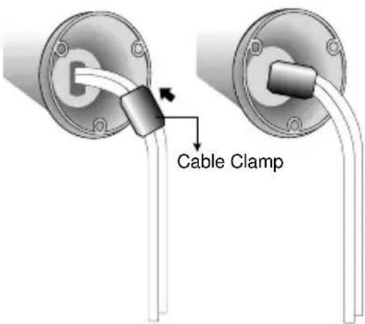
text_image
Cable ClampFigure 1-2
- Install the Bullet Camera to the wall.
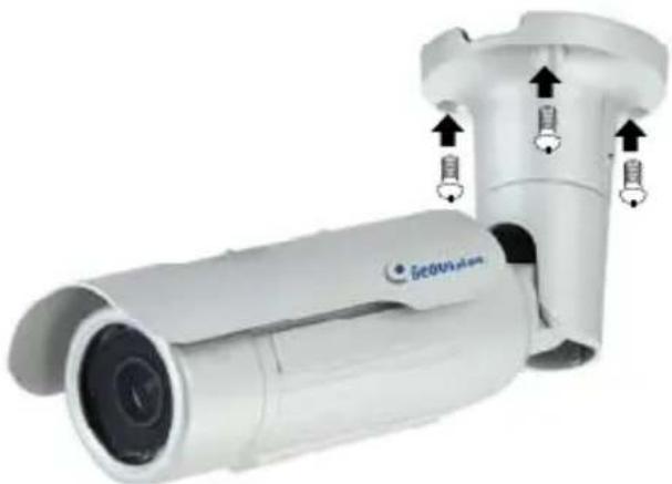
natural_image
Exterior view of a security camera with mounted sensor and control buttons (no text or symbols visible)Figure 1-3
- Remove the protection sticker from the camera's cover
- Connect the power, network and other wires to the Bullet Camera.
See 1.4.1 Connecting the Camera.
- Access the live view. For details, see 2.1. Accessing the Live View, GV-IPCam H.264 Firmware Manual.
- Adjust angles of the camera body based on the live view. Three shafts can be adjusted. See 1.4.2 Adjusting the Angles.
- Loosen the camera's cover, adjust the focus of the camera and optionally insert a micro SD card (SD/SDHC, version 2.0, Class 10) into the SD card slot. See 1.4.3 Adjusting Lens and Inserting a Memory Card.
- Fasten the camera's cover.
- Install the sun-shield cover to the Bullet Camera. For details, see 1.4.4 Installing the Sun-Shield Cover.
1.4.1 Connecting the Camera
Wire Definition for Auto Iris Models
The 7-Pin Data Cable provides connections for power, ground, 1 sensor input, 1 alarm output, audio input and audio output. The wires are illustrated and defined below:
Digital In (Red)
DC 12V+ / AC 24V + (Brown)
Digital Out (Orange)
DC 12V- / AC 24V - (Black)
GND (Yellow)
Audio In (Red)
Audio Out (Green)
Ethernet (PoE)
Figure 1-4
No. Wire Color Definition
1 Red Digital In
2 Brown DC 12V+ / AC 24V+
3 Orange Digital Out
4 Black DC 12V- / AC 24V-
5 Yellow Ground
6 Red RCA Audio in
7 Green RCA Audio out
Note that the Audio In and Out connectors may also come as terminal blocks:
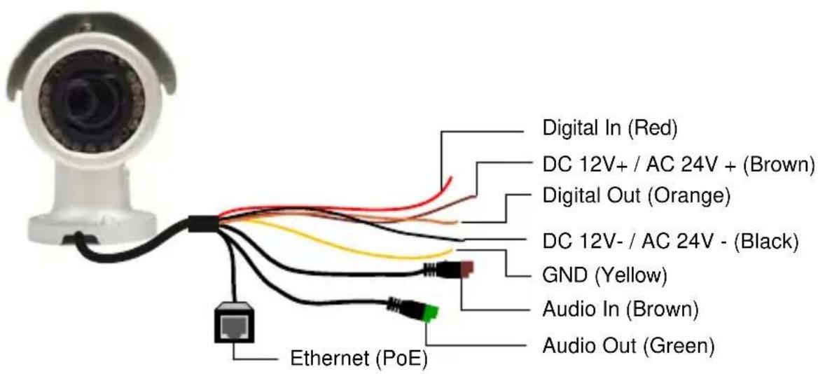
text_image
Digital In (Red) DC 12V+ / AC 24V + (Brown) Digital Out (Orange) DC 12V- / AC 24V - (Black) GND (Yellow) Audio In (Brown) Audio Out (Green) Ethernet (PoE)Figure 1-5
| No. | Wire Color Definition | |
| 1 | Red Digital | In |
| 2 Brown DC 12V+ / AC 24V+ | ||
| 3 | Orange Digital | Out |
| 4 Black DC 12V- / AC 24V- | ||
| 5 | Yellow Ground | |
| 6 Brown terminal block Audio in | ||
| 7 Green terminal block Audio out | ||
Power Connection
Use one of the following methods to supply power to the camera.
- Use a Power over Ethernet (PoE) adapter to connect the camera to the network, and the power will be provided at the same time.
-
Plug the power adaptor to the terminal block as shown below.
-
Insert the black wire of the Bullet Camera to the left pin (+) and the brown wire to the right pin (-).
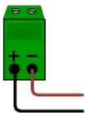
natural_image
Green electrical component with two terminals and a red wire, no visible text or symbolsFigure 1-6
- Connect the DC 12V Power Adapter to the Terminal Block.

text_image
Terminal Block DC 12V Power AdaptorFigure 1-7
I/O Device Connection
The camera supports one digital input and one digital output of dry contact.
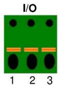
text_image
I/O 1 2 3Figure 1-8
| Pin Function | ||
| 1 | Digital | Output |
| 2 | GND | |
| 3 | Digital | Input |
For details on how to enable an installed I/O device, see 4.2 I/O Settings, GV-IPCam H.264 Firmware Manual.
Voltage Load Expansion (Optional)
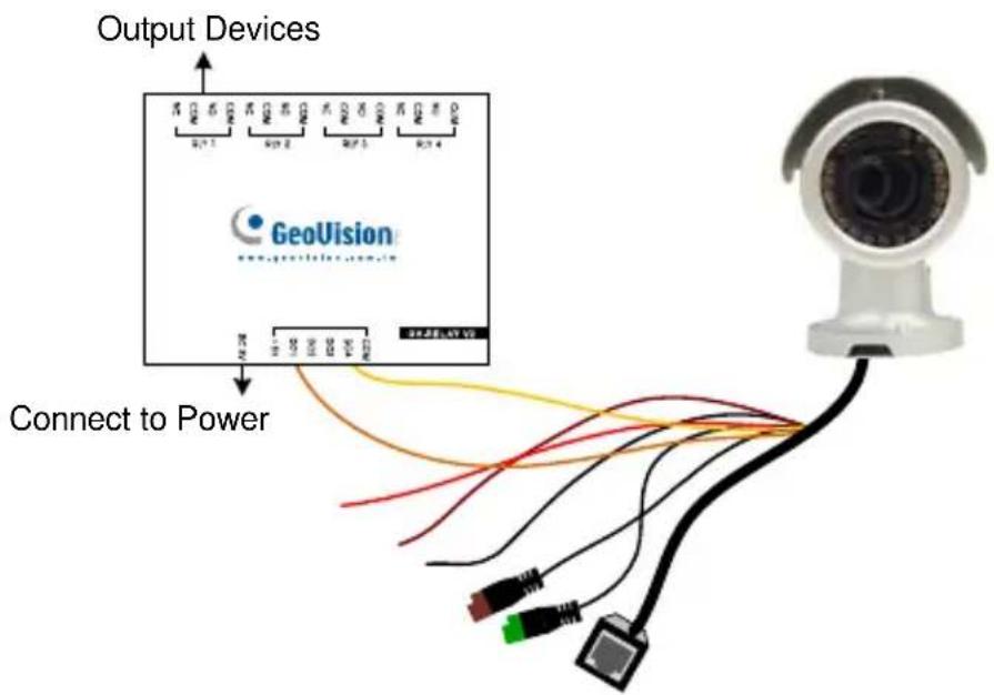
The camera can only drive a maximum load of 200mA 5V DC. To expand the maximum voltage load to 10A 250V AC, 10A 125V AC or 5A 100V DC, connect the camera to a GV-Relay V2 module (optional product). Refer to the figure and table below.
text_image
Output Devices GeoVision www.geovision.com.cn Connect to PowerFigure 1-9
| GV-Relay V2 Bullet Camera | |
| COM | Ground |
| DO1 Digital Out (Orange) |
(Yellow)
1.4.2 Adjusting the Angles
The Bullet Camera is designed to be adjustable in three shafts for easy and flexible installation.
First Shaft
You can adjust the camera body by 360 degrees to the right or the left.
- Unscrew the panning lock screw with the torx wrench.
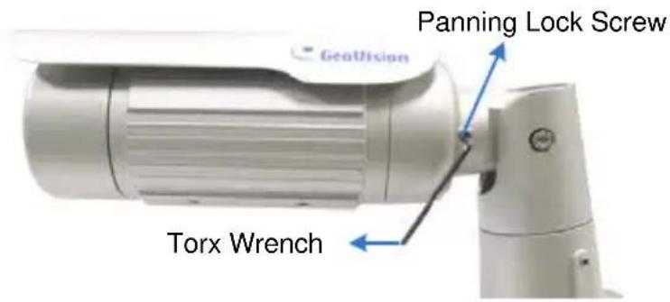
text_image
Panning Lock Screw GeoVision Torx WrenchFigure 1-10
- Adjust the angle of camera body to the right or the left, and fasten the panning lock screw.
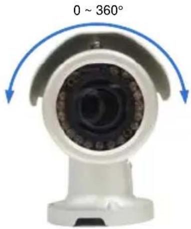
text_image
0 ~ 360°Figure 1-11
Second Shaft
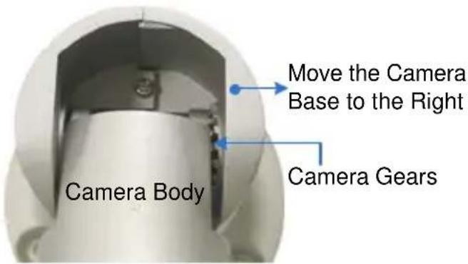
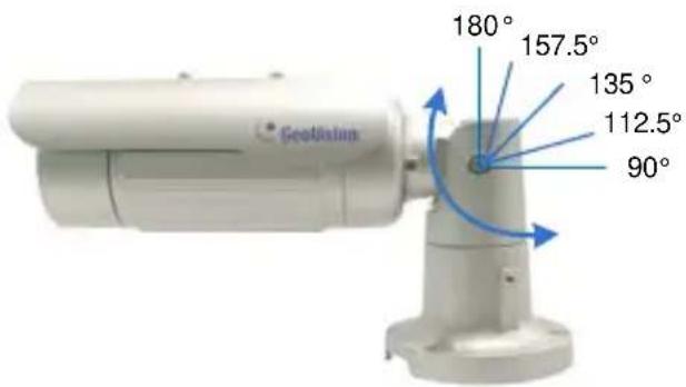
You can adjust the camera body up and down by 90, 112.5, 135, 157.5 or 180 degrees by using the gears inside the camera body and the camera base.
- Unscrew the tilting lock screw with the torx wrench.
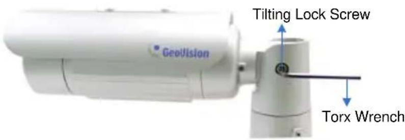
text_image
GeoVision Tilting Lock Screw Torx WrenchFigure 1-12
- Hold the camera body, and move the camera base to the right to separate the camera gears.
text_image
Move the Camera Base to the Right Camera Body Camera GearsFigure 1-13
- Adjust the angle of camera body to 90^ , 112.5^ , 135^ , 157.5^ or 180^ . Then move the camera base to the left to combine the gears.
text_image
Geolateral 180° 157.5° 135° 112.5° 90°Figure 1-14
- Fasten the tilting lock screw.
Third Shaft
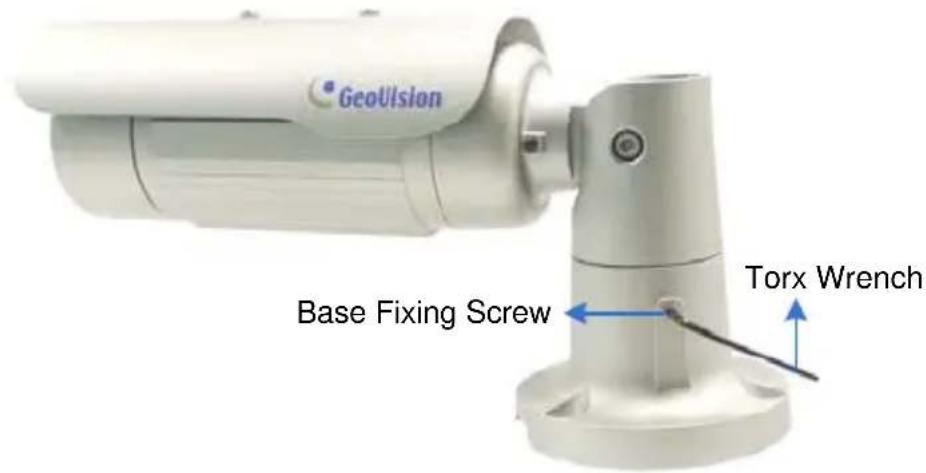
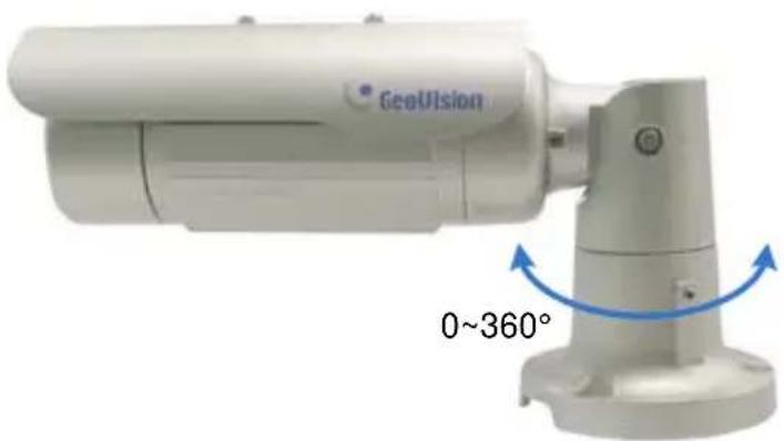
You can adjust the camera base by 360°.
- Unscrew the base fixing screw with the torx wrench.
text_image
GeoVision Base Fixing Screw Torx WrenchFigure 1-15
- Adjust the angle of camera base, and fasten the base fixing screw.
text_image
GeoVision 0~360°Figure 1-16
1.4.3 Adjusting Lens and Inserting a Memory Card
To adjust the camera's zoom and focus or to insert a micro SD card (SD/SDHC, version 2.0 only, Class 10), follow the steps below.
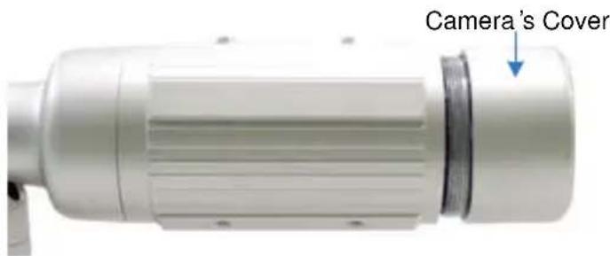
- Loosen the camera's cover.
text_image
Camera's CoverFigure 1-17
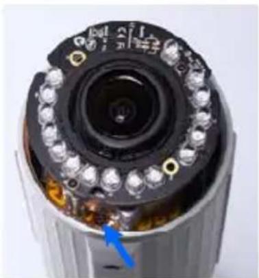
For GV-BL2511-E / 5311-E, loosen the camera's cover and the screw as indicated below.
natural_image
Close-up of a camera lens assembly with visible internal components and a blue arrow pointing to a component (no text or symbols)Figure 1-18 (GV-BL2511-E / 5311-E)
- To adjust for image clarity, follow the steps below.
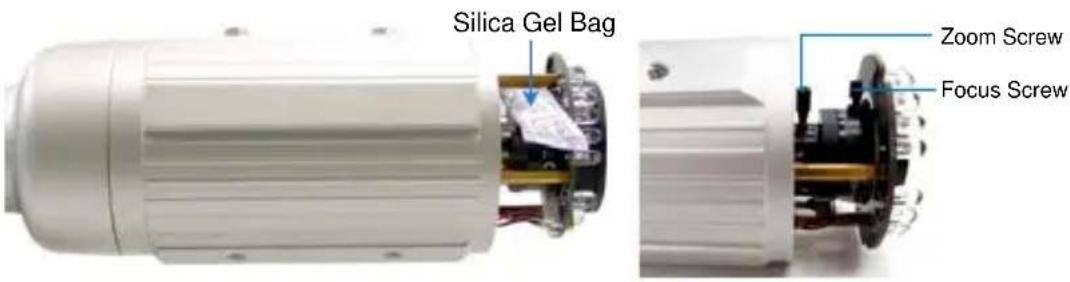
- For models with zoom and focus screws, pull out the camera and remove the silica gel bag to access its focus and zoom screws. Use GV-IP Device Utility to help you. For details, see 2.2 Adjusting Image Clarity, GV-IPCam H.264 Firmware Manual.
text_image
Silica Gel Bag Zoom Screw Focus ScrewFigure 1-19
- For motorized varifocal lens models, adjust for image clarity through the Web interface. For details, see Zoom, Focus Change, and Focus Mode settings in 3.2.2 The Control Panel of the Live View Window, GV-IPCam H.264 Firmware Manual.
- To insert a micro SD card, follow the steps below.
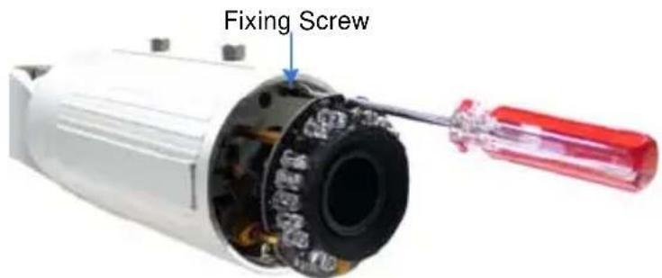
A. Loosen the fixing screw.
text_image
Fixing ScrewFigure 1-20
B. Slightly pull out the camera module.
C. Insert a micro SD card (SD/SDHC, version 2.0 only, Class 10) into the memory card slot.
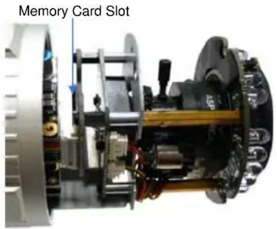
text_image
Memory Card SlotFigure 1-21
D. Push the camera back and fasten the fixing screw.
- Insert a new silica gel bag to the camera module and fasten the camera's cover within 2 minutes of opening the silica gel bag package.
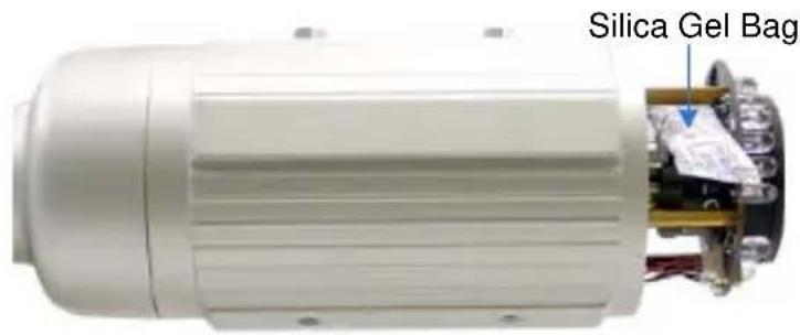
text_image
Silica Gel BagFigure 1-22
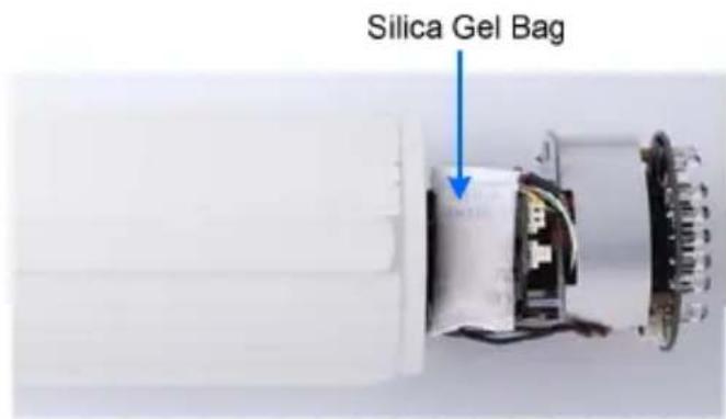
text_image
Silica Gel BagFigure 1-23 (GV-BL2511-E/5311-E)
IMPORTANT: The silica gel loses its effectiveness when the dry camera is opened. To prevent the lens from fogging up, replace the silica gel bag every time when you open the camera and conceal the gel bag in the camera within two minutes of exposing to the open air.
1.4.4 Installing the Sun-Shield Cover
After setting up the Bullet Camera, now you can install the sun-shield cover to the camera.
- Fasten the hexagon screws either on top or below the camera.
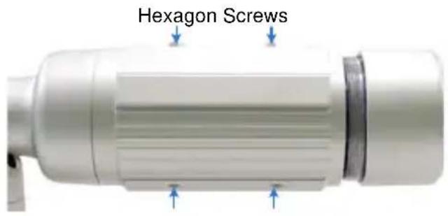
text_image
Hexagon ScrewsFigure 1-24
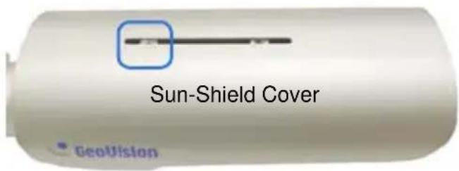
- Put the sun-shield cover on top of hexagon screws. Make sure to aim the rear hexagon screw at the edge of the sun-shield cover's aperture for optimal sun-shield performance.
text_image
Sun-Shield Cover GeoVisionFigure 1-25
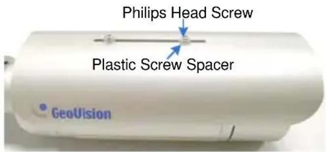
- Fasten the Philips head screws with the plastic screw spacers.
text_image
Philips Head Screw Plastic Screw Spacer GeoVisionFigure 1-26
1.5 Loading Factory Default
- Keep the power and network cables connected to the camera.
- Loosen the camera's cover and remove the Silica Gel Bag.
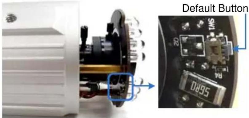
- Press and hold the default button for 8 seconds.
text_image
Default Button 56R0Figure 1-27
- Release the default button. When the process of loading default settings is completed, the camera reboots automatically.
- Insert a new Silica Gel Bag and fasten the camera's cover immediately.
Chapter 2 Bullet Camera (Part II)
The Bullet Cameras are specifically designed for outdoors. They are weatherproof (IP67) and equipped with IR LEDs for infrared illumination in night vision applications. The models described in this chapter use P-Iris, which allows for precise control of exposure, producing images with better clarity and contrast.
The WDR Pro models enhance the image by processing contrasting intensity of light. The super low lux models can produce color live view in near darkness. The motorized varifocal lens models allow the user to adjust the focus and zoom through the Web interface. The arctic models can withstand extreme temperatures (-40°C \~ 50°C / -40°F \~ 122°F). For related models, see 2.2 Features.
| Model No. | Specifications | Description | |
| GV-BL1501 | Varifocal lens | P-Iris, f: 3 ~ 9 mm, F/1.2, 1/2.7"ø 14 mm Lens Mount | 1.3 MP, H.264, Super Low Lux |
| GV-BL2501 | 2 MP, H.264, Super Low Lux | ||
| GV-BL3401 | 3 MP, H.264, WDR Pro | ||
| GV-BL1511 | Motorized varifocal lens | 1.3 MP, H.264, Super Low Lux, 3X Optical Zoom | |
| GV-BL2511 | 2 MP, H.264, Super Low Lux, 3X Optical Zoom | ||
| GV-BL3411 | 3 MP, H.264, WDR Pro, 3X Optical Zoom | ||
| GV-BL5311 | P-Iris, f: 4.5 ~ 9 mm, F/1.2, 1/2.7"ø 14 mm Lens Mount | 5 MP, H.264, 2X Optical Zoom | |
| GV-BL2511-E | Motorized varifocal lens, extreme temperature tolerance | P-Iris, f: 3 ~ 9 mm, F/1.2, 1/2.7"ø 14 mm Lens Mount | 2 MP, H.264, Super Low Lux, 3X Optical Zoom |
| GV-BL5311-E | P-Iris, f: 4.5 ~ 9 mm, F/1.2, 1/2.7"ø 14 mm Lens Mount | 5 MP, H.264, 2X Optical Zoom | |
2.1 Packing List
- Bullet Camera
- Self Tapping Screw x 3
- Plastic Screw Anchor x 3
- Torx Wrench x 3
- Sun-Shield Cover Kit (Sun-Shield Cover, Philips Head Screw x 2, Plastic Screw Spacer x 2, and Hexagon Screw x 2)
- Silica Gel Bag x 2
• 2-Pin Terminal Block
• 3-Pin Terminal Block - Power Adapter
- Installation Sticker
- Ruler
- Stand Kit (Conduit Converter, PG21 Conduit Connector, RJ-45 Connector, M3 Screw x 2, Cable Tie)
- Mounting Kit (M4 Screw x 3, Nut x 3, Plate x 3)
• GV-IPCAM H.264 Software DVD
• GV-NVR Software DVD - Warranty Card
Note:
- The power adapter can be excluded upon request.
- The Mounting Kit is used for wall corner and pole installations using GV-Mount300 / 310 / 400 / 410 (optional). For details, see GV-Mount Accessories Installation Guide on the Software DVD.
2.2 Features
- Image sensor
| Camera Model Image Sensor | |
| GV-BL1501 / 1511 | 1/3” progressive scan super low lux CMOS |
| GV-BL5311 / 5311-E 1/2.5” | progressive scan CMOS |
| GV-BL3401 / 3411 1/3.2” | progressive scan CMOS |
| GV-BL2501 / 2511 / 2511-E | 1/2.8” progressive scan super low lux CMOS |
• Dual streams from H.264 or MJPEG
- Frame rate
| Camera Model Frame Rate | |
| GV-BL1501 / 1511 30 fps at 1 | 280 x 1024 |
| GV-BL2501 / 2511 / 2511-E 30 fps at 1920 x 1080 | |
| GV-BL3401 / 3411 20 fps at 2 | 048 x 1536 |
| GV-BL5311 / 5311-E 10 fps at 2560 x 1920 | |
• Day and night function (with removable IR-cut filter)
- Megapixel lens
- Motorized varifocal lens for remote focus/zoom adjustment (GV-BL1511 / 2511 / 3411 / 5311 and GV-BL2511-E / 5311-E only)
• P-iris for auto iris adjustment
- Wide Dynamic Range Pro (GV-BL3401 / 3411 only)
- Ingress protection (IP67)
• Vandal resistance (IK10 for metal casing)
- Two-way audio
• Built-in heater and fan (GV-BL2511-E / 5311-E only)
• One sensor input and alarm output
- Micro SD card slot (SD/SDHC) for local storage
- NAS recording
- Recording assigned by GV-Edge Recording Manager (Windows & Mac)
- DC 12V / AC 24V / PoE (IEEE 802.3af, not supported by GV-BL2511-E / 5311-E)
- Intelligent IR
• Maximum IR distance
| Camera Model Maximum IR Distance | |
| GV-BL5311 / 5311-E 40 m (131 ft) | |
| GV-BL2501 / 2511 / 2511-EGV-BL3401 / 3411 | 50 m (164 ft) |
| GV-BL1501 / 1511 70 m (230 ft) | |
- Wide temperature tolerance for GV-BL2511-E / 5311-E (-40°C \~ 50°C / -40°F \~ 122°F)
• 3D noise reduction (GV-BL1501 / 1511 / 2501 / 2511 / 2511-E only)
• 2D noise reduction (GV-BL3401 / 3411 / 5311 / 5311-E only) - Defog
- Motion detection
- Tampering alarm
- Visual automation
- Text overlay
- Privacy mask
- IP address filtering
• Smart Phone and 3GPP support
• 31 languages on Web interface
• ONVIF (Profile S) conformant
2.3 Overview
Twist off the camera cover to access the following:
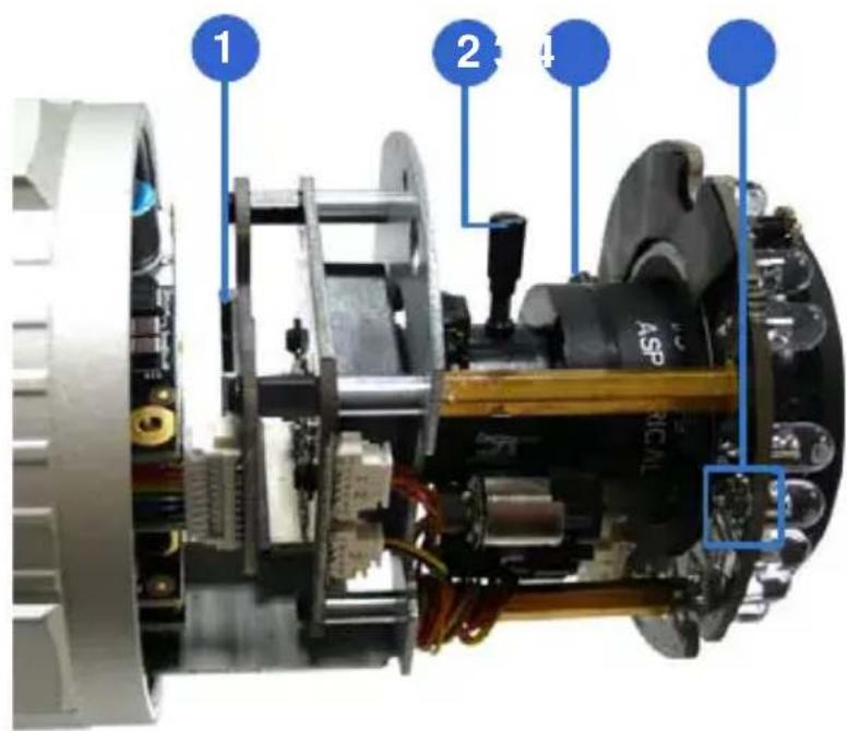
text_image
1 2 4Figure 2-1
| No. | Name | Description | |
| 1 | Memory Card Slot | Receives a micro SD card (SD/SDHC, version 2.0 only, Class 10). | |
| 2 | Zoom Screw Holds the zoom lens in place. | ||
| 3 | Focus Screw Holds the focus lens in place | ||
| 4 | Default Button | Resets all configurations to factory default. For details, see 1.5 Loading Factory Default. | |
To access the following interface, remove the camera base using the supplied torx wrench.
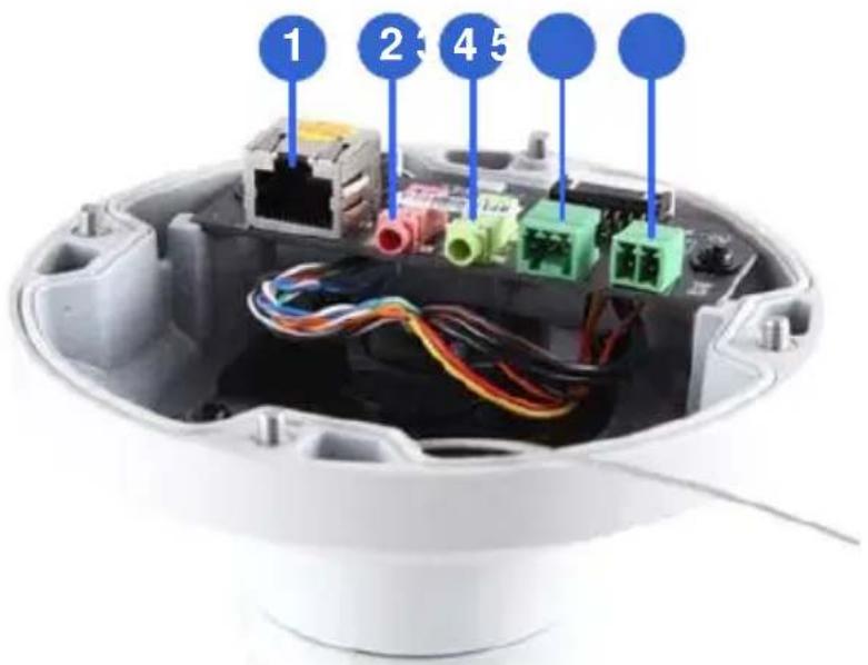
text_image
1 2 4 5Figure 2-2
| No. | Name | Description | |
| 1 | LAN / PoE | Connects to a | 10/100 Ethernet or PoE. |
| 2 | Audio In | Connects a microphone for audio input. | |
| 3 | Audio Out | Connects a speaker for audio output. | |
| 4 | I/O | Terminal | Connects to I/O devices. For details, see Block I/O Terminal, 2.5 Connecting the Camera. |
| 5 | DC | 12V Port Connects to power. | |
2.4 Installation
Follow the steps below to install the Bullet Camera.
- Paste the supplied sticker to the ceiling/wall. For wall installations, make sure the arrow on the sticker points toward the ceiling.
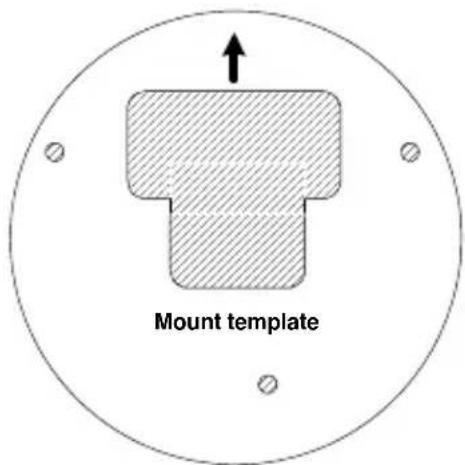
text_image
Mount templateFigure 2-3
- Drill the shaded area, and insert the screw anchor into the three holes.
- Loosen the indicated screws with the supplied torx wrench to remove the base.
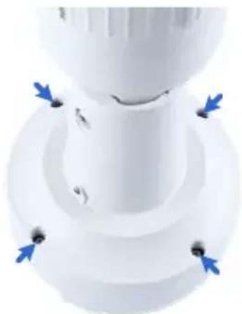
natural_image
Close-up of a white plastic mechanical component with blue directional arrows indicating movement or force (no text or symbols)Figure 2-4
- Loosen the indicated screws and remove the back plate.
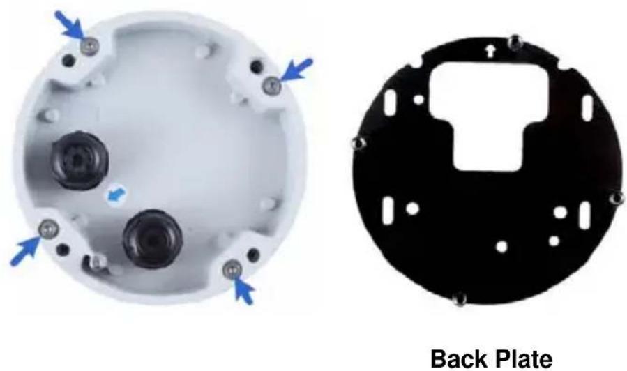
Figure 2-5
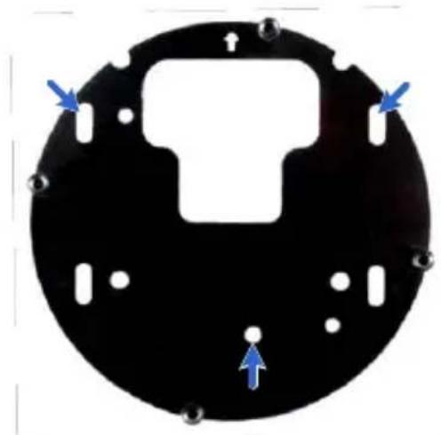
- Align and secure the black plate to the wall/ceiling with the supplied self-tapping screws.
natural_image
Circular black electronic component with white cutouts and blue directional arrows indicating orientation (no text or symbols)Figure 2-6
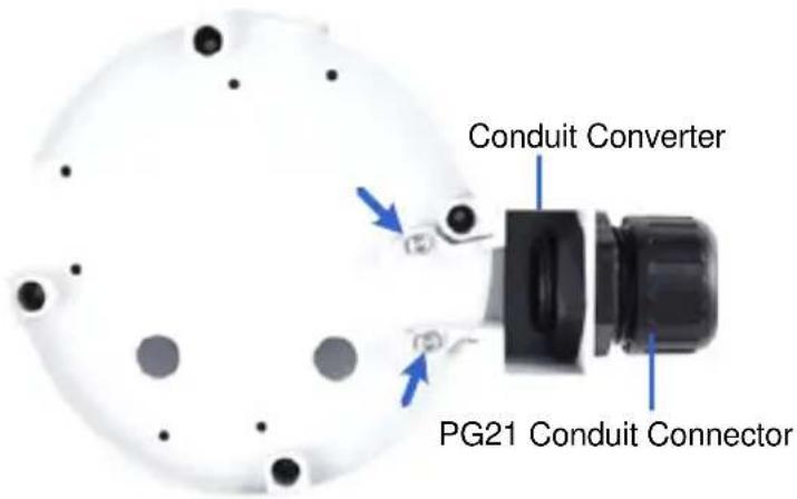
- To use a pipe (optional), install the conduit converter using the supplied M3 screws.
text_image
Conduit Converter PG21 Conduit ConnectorFigure 2-7
IMPORTANT: For GV-BL2511-E / 5311-E connected with a power adapter, only install the conduit converter to the indicated exit.
- Install the Ethernet cable.
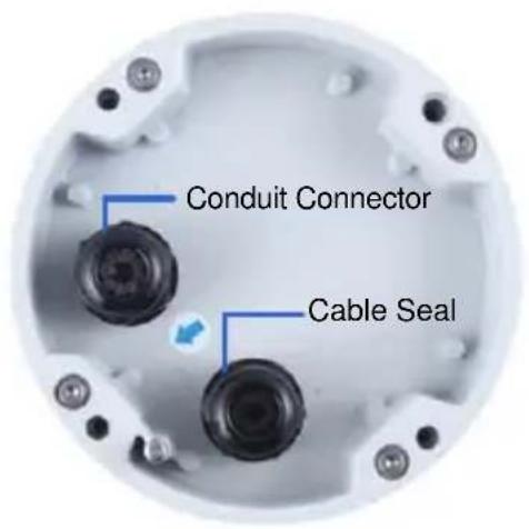
A. Twist off and remove the cable seal and the conduit connector.
text_image
Conduit Connector Cable SealFigure 2-8
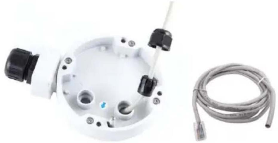
B. Thread an Ethernet cable (with no RJ-45 connector on one end) from the back panel through the conduit converter (optionally installed at step 6) and then through the cable seal.
natural_image
White mechanical device with black connectors and a coiled cable, no visible text or symbolsFigure 2-9
IMPORTANT: Use the supplied ruler and leave about 10 cm of the Ethernet cable between the connector and the cable seal.
C. Re-install the cable seal. Make sure it is installed tightly to waterproof the camera.
- Thread wires into the camera.
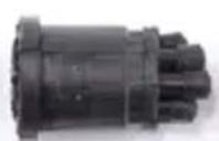
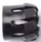
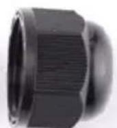
A. Disintegrate the removed conduit connector. You should have 4 parts:

natural_image
Close-up of a black threaded mechanical component (no visible text or symbols)1
2
3
4
Figure 2-10
B. Remove the terminal block from the supplied power adapter.
C. Optionally thread audio wires, adapter wires, and I/O wires through the conduit converter and then through part 1, 2, 3, and 4 of the conduit connector.
Tip: To make the threading easier, it is advised to thread the wires in the order described here.
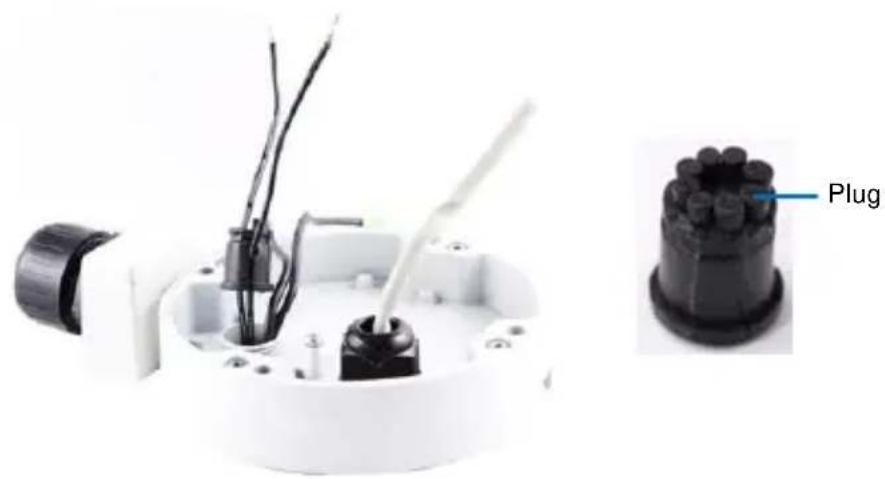
For part 2, there are 8 holes each labeled with its diameter.
Remove the plugs and push the wires to the corresponding hole listed below:
natural_image
Close-up of a mechanical component with wires and a labeled plug (no text or symbols on main subject)Figure 2-11
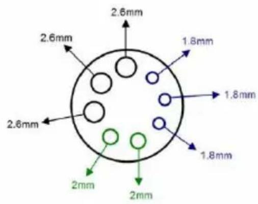
text_image
2.6mm 2.6mm 1.8mm 1.8mm 1.8mm 2.6mm 2.6mm 2mm 2mm2.6 mm: Audio
2 mm: DC12V / AC24V
1.8 mm: DIDO
Figure 2-12
IMPORTANT:
- Use the supplied ruler and leave about 10 cm of audio, power, and I/O wires between their connectors and the cable seal.
- The plugs are used to prevent water from entering the camera housing. Keep the unused holes plugged and save the removed plugs for future use.
-
Only thread the wires through their designated holes on the conduit connector to make sure the wires are properly sealed.
-
Install the base to the back plate on the wall.
- Connect the wires to the camera.
A. Install the terminal blocks to the power adapter and I/O devices. See Power Connection and I/O Device Connections in 2.5 Connecting the Camera.
B. Install the supplied RJ-45 connector to the Ethernet cable.
C. Plug all the connectors to the camera panel.
- Tie the wires with the supplied cable tie and re-install the base to the camera. You may need to rotate the base for the wires to fit.
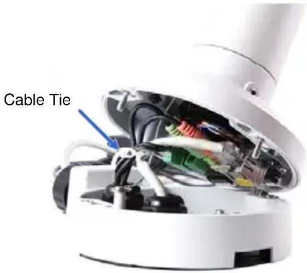
text_image
Cable TieFigure 2-13
GeoVision
- Access the live view. For details, see 2.1 Accessing the Live View, GV-IPCam H.264 Firmware Manual.
- Adjust the angles of the camera based on the live view. Three shafts can be adjusted. See 1.4.2 Adjusting the Angles.
- To adjust the focus and insert a micro SD card (SD/SDHC, version 2.0, Class 10), see 1.4.3 Adjusting Lens and Inserting a Memory Card.
- Install the sun-shield cover. For details, see 1.4.4 Installing the Sun-Shield Cover.
2.5 Connecting the Camera
Power Connection
Use one of the following methods to supply power to the camera. Note that GV-BL2511-E / 5311-E do not support PoE.
- Use a Power over Ethernet (PoE) adapter to connect the camera to the network, and the power will be provided at the same time.
- Plug the power adaptor to the terminal block as shown below. For all models (except GV-BL2511-E / 5311-E), insert the striped wire to the left pin (+); for GV-BL2511-E / 5311-E, insert the striped wire to the right pin (-).
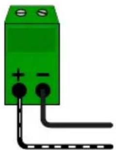
natural_image
Green electrical component with two terminals and a black wire, no visible text or symbolsFigure 2-14 (All Models except GV-BL2511-E / 5311-E)
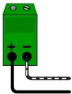
natural_image
Green electrical component with two terminals and a black wire, no visible text or symbolsFigure 2-15 (GV-BL2511-E / 5311-E)
I/O Device Connection
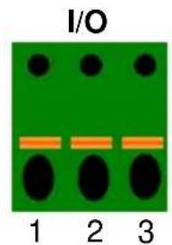
The camera supports one digital input and one digital output of dry contact.
text_image
I/O 1 2 3Figure 2-15
| Pin Function | ||
| 1 | Digital | Output |
| 2 | GND | |
| 3 | Digital | Input |
For details on how to enable an installed I/O device, see 4.2 I/O Settings, GV-IPCam H.264 Firmware Manual.
Chapter 3 Ultra Bullet Camera
The Ultra Bullet Camera is a series of light-weighted cameras designed for outdoor environments. The camera adheres to the IP67 standard and has full protection against dust and jets of water. The Ultra Bullet Cameras are available in motorized varifocal lens and fixed lens at 1.3, 2 and 3 megapixels. The motorized varifocal lens models allow the user to remotely adjust the focus and zoom through the Web interface. The WDR Pro models can enhance the live view by processing contrasting intensity of lights. The super low lux models are able to provide color live view in near darkness. For related models, see 3.2 Features.
| Model No. | Specifications | Description | |
| GV-UBL1211 | Varifocal Lens | Auto Iris, f: 3 ~ 9 mm, F/1.2, 1/2.7"ø 14 mm Lens Mount | 1.3 MP Low Lux, H.264, D/N, 3X Optical Zoom |
| GV-UBL1511 | 1.3 MP Super Low Lux, H.264, D/N, 3X Optical Zoom | ||
| GV-UBL2411 | 2 MP, H.264, D/N, WDR Pro, 3X Optical Zoom | ||
| GV-UBL2511 | 2 MP Super Low Lux, H.264, D/N, 3X Optical Zoom | ||
| GV-UBL3411 | 3 MP, H.264, D/N, WDR Pro, 3X Optical Zoom | ||
| GV-UBL1301-0F | Fixed Lens | Fixed Iris, f: 2.8 mm,F/2.0, 1/3” M12 LensMount | 1.3 MP, Low Lux, H.264, D/N |
| GV-UBL1301-1F | Fixed Iris, f: 4 mm,F/1.5, 1/3” M12 LensMount | ||
| GV-UBL1301-2FGV-UBL1301-3F | Fixed Iris, f: 4 / 8 mm,F/1.6, 1/3” M12 LensMount | 1.3 MP, Low Lux, H.264, D/N | |
| GV-UBL2401-0F | Fixed Iris, f: 2.8 mm,F/2.0, 1/3” M12 LensMount | 2 MP, H.264,D/N, WDR Pro | |
| GV-UBL2401-1F | Fixed Iris, f: 4 mm,F/1.5, 1/3” M12 LensMount | ||
| GV-UBL2401-2FGV-UBL2401-3F | Fixed Iris, f: 8 / 12 mm,F/1.6, 1/3” M12 LensMount | ||
| GV-UBL3401-0F | Fixed Iris, f: 2.8 mm,F/2.0, 1/3” M12 LensMount | 3 MP, H.264,D/N, WDR Pro | |
| GV-UBL3401-1F | Fixed Iris, f: 4 mm,F/1.5, 1/3” M12 LensMount | ||
| GV-UBL3401-2FGV-UBL3401-3F | Fixed Iris, f: 8 / 12 mm,F/1.6, 1/3” M12 LensMount | ||
3.1 Packing List
- Ultra Bullet Camera (with Waterproof or Non-Waterproof LAN connector)
- Camera Stand
- Black Rubber
- Self Tapping Screw x 3
- Plastic Screw Anchor x 3
- Torx Wrench
- Sun-Shield Cover Kit (Sun-Shield Cover, Philips Head Screw x 2, Plastic Screw Spacer x 2 and Hexagon Screw x 2)
- Cable connector (for waterproof LAN connector only)
- Silica Gel Bag x 2
• 2-Pin Terminal Block - Data cable
- Power Adapter
• GV-IPCAM H.264 Software DVD
• GV-NVR Software DVD - Warranty Card
Note: The power adapter can be excluded upon request.
3.2 Features
- Image sensor
| Camera Model Image Sensor | |
| GV-UBL1211 | 1/3” progressive scan |
| GV-UBL1301 Series 1 | 1/2.5” progressive scan CMOS |
| GV-UBL1511 1/3” progressive scan super low lux CMOS | |
| GV-UBL2511 | 1/2.8” progressive scan super low lux CMOS |
| GV-UBL2411 / 3411GV-UBL2401 SeriesGV-UBL3401 Series | 1/3.2” progressive scan CMOS |
• Dual streams from H.264 or MJPEG
- Frame rate
| Camera Model Frame Rate | |
| GV-UBL1211 / 1511GV-UBL1301 Series | 30 fps at 1280 x 1024 |
| GV-UBL2411 / 2401 SeriesGV-UBL2511 | 30 fps at 1920 x 1080 |
| GV-UBL3411 / 3401 Series 20 | fps at 2048 x 1536 |
- Motorized varifocal lens for remote focus/zoom adjustment (for GV-UBL1211 / 1511 / 2411 / 2511 / 3411 only)
• Day and night function (with removable IR-cut filter) - Wide Dynamic Range Pro (WDR Pro) (for GV-UBL2411 / 3411 / 2401 Series / 3401 Series only)
-
Defog
• Ingress protection (IP67)
• Vandal resistance (IK10 for metal casing)
• One alarm input and sensor output -
Micro SD card slot (SD/SDHC) for local storage
- NAS recording
• Recording assigned by GV-Edge Recording Manager (Windows & Mac) - Intelligent IR
• 3D noise reduction (for GV-UBL1511 / 2511)
• 2D noise reduction (except for GV-UBL1511 / 2511) - Motion detection
- Tampering alarm
- Visual automation
- Text overlay
- Privacy mask
- IP address filtering
• DC 5V / PoE (IEEE 802.3af) - Megapixel lens
• Support for iPhone, iPad, Android and 3GPP
• 31 languages on Web interface
• ONVIF (Profile S) conformant
3.3 Overview
Panel

text_image
Power DI/DO LAN/PoE 1 2 3 Default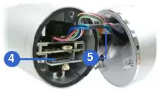
natural_image
Interior view of a cylindrical electronic device showing internal components and wiring (no text or symbols visible)Figure 3-1
| No. | Name Description | |
| 1 | Power & I/O Connector | Connects to the data cable. For details, see 3.4.2 Connecting the Camera. |
| 2 | Default Button | Resets all configurations to factory default. For details, see 3.5 Loading Factory Default. |
| 3 LAN / PoE Cable Connects to a 10/100 Ethernet or PoE. | ||
| 4 | Memory Card Slot | Receives a micro SD card (SD/SDHC, version 2.0 only, Class 10). |
| 5 Silica gel bag Desiccant that keeps the camera housing dry. | ||
LAN Connector
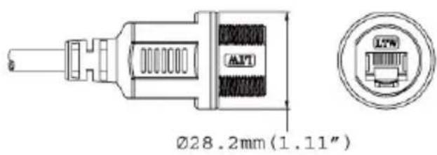
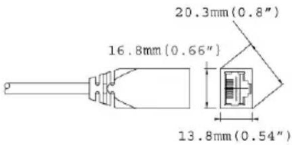
The Ultra Bullet Camera provides two connector types. Select an option based on your installation environment.
- Option 1 (Waterproof)
text_image
Ø28.2mm (1.11")To waterproof the cable, install the supplied cable connector. See 3.4.1 Waterproofing the Cable.
- Option 2 (Smaller and non-waterproof)
text_image
20.3mm(0.8") 16.8mm(0.66") 13.8mm(0.54"3.4 Installation
You can install the camera to the ceiling or wall. Follow the steps below.
- Optionally insert a micro SD card to the camera.
A. Unscrew and open the back panel with the supplied torx wrench.
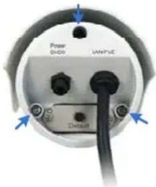
text_image
Power Diode IANPTUE DefaultFigure 3-2
B. Insert a micro SD card (SD/SDHC, version 2.0 only, Class 10) into the card slot and replace the silica gel bag (see Figure 3-1).
IMPORTANT:
-
The silica gel loses its effectiveness when the dry camera is opened. To keep the interior dry, replace the silica gel bag every time you open the camera and conceal the gel bag in the camera within two minutes of exposing to the open air.
-
Make sure the I/O connector is firmly plugged.
C. Secure the back cover with the supplied torx wrench.
- Install the sun-shield cover to the camera.
A. Fasten the hexagon screws on the top of the camera.
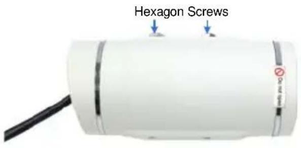
text_image
Hexagon ScrewsFigure 3-3
IMPORTANT: To avoid waterproofing failures, do not open the front cover of the camera and the screw on the camera body. See Note for Waterproofing Failures.
B. Put the sun-shield cover on the top of the camera. For optimal sun-shield performance, make sure the rear hexagon screw is at the end of the opening.
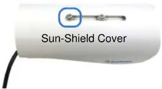
text_image
Sun-Shield CoverFigure 3-4
IMPORTANT: The GeoVision logo on the sun-shield cover should be closer to the front of the camera.
C. Fasten the Philips head screws with the plastic screw spacers to mount the sun-shield cover onto the camera.
- Ceiling Mount: Fasten one Philips head screw to the top of the camera.
- Wall Mount: Fasten two Philips head screws to the top of the camera.
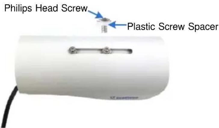
text_image
Philips Head Screw Plastic Screw SpacerFigure 3-5
- Install the camera to the wall or ceiling.
A. Ceiling Mount: Secure the black rubber and the camera stand to the other screw hole on the top.
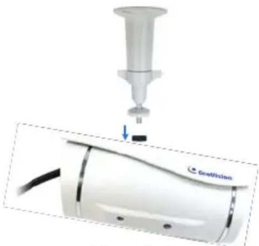
natural_image
Medical device with needle inserted into a cylindrical component, showing internal structure and a small component labeled 'GenVision' (no text or symbols on the device itself)Figure 3-6
B. Wall Mount: Secure the black rubber and the camera stand to one of the screw holes on the bottom.
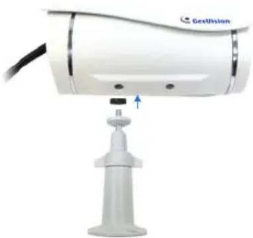
natural_image
Close-up of a white GEU Vision surveillance camera with a mounted sensor base and cable (no text or symbols visible)Figure 3-7
- Use the screw anchors and self-tapping screws to secure the camera to the wall.
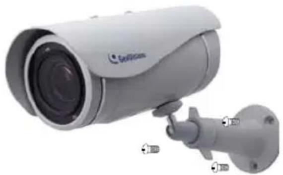
natural_image
Exterior view of a security camera with mounted sensor and wall-mounted cable (no visible text or symbols)Figure 3-8
- Remove the protection sticker from the camera's cover.
- Connect the wires and cable connector to the camera. See 3.4.1 Waterproofing the Cable and 3.4.2 Connecting the Camera.
- Access the live view. For details, see 2.1 Accessing the Live View, GV-IPCam H.264 Firmware Manual.
- Adjust angles of the camera body based on the live view.
- For varifocal models (GV-UBL1211 / 1511 / 2411 / 2511 / 3411), adjust the focus. For details, see 3.2.2 The Control Panel of the Live View Window, GV-IPCam H.264 Firmware Manual.
3.4.1 Waterproofing the Cable
Waterproof the option 1 LAN / PoE cable (see 3.3 Overview) using the supplied cable connector. The cable connector can be dissembled into 5 parts:
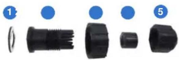
natural_image
Five black plastic connectors with blue circular markers, labeled 1 to 5 (no text or symbols on parts)Figure 3-9
- Cut off the RJ-45 connector on one end of the Ethernet cable.
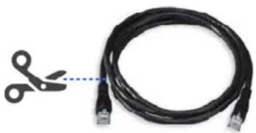
natural_image
Close-up of a black USB cable with a pair of scissors cutting out, alongside a separate network interface (no text or symbols visible)Figure 3-10
- Connect the Ethernet cable to the LAN / PoE connector (No. 3, Figure 3-1) on the camera.
- Slide the components through the Ethernet cable as shown below.

text_image
A 1 2 3 4 5Figure 3-11
-
Paste the item 1 sticker to item 2.
-
Move all the components toward the LAN / PoE connector, fit item 4 to item 2, secure item 3 to the LAN / PoE connector (Item A) and finally secure item 5 to item 2 tightly.
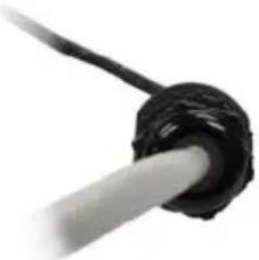
natural_image
Close-up of a black cable with a white rod inserted, no visible text or symbolsFigure 3-12
IMPORTANT: Item 5 must be secured tightly to waterproof the LAN / PoE connector.
- Prepare an RJ-45 connector, reconnect the RJ-45 connector to the cable, and then connect the camera to network.
3.4.2 Connecting the Camera
Wire Definition
The camera's 4-pin data cable provides connections for power, ground, 1 sensor input and 1 alarm output. The wires are defined below:
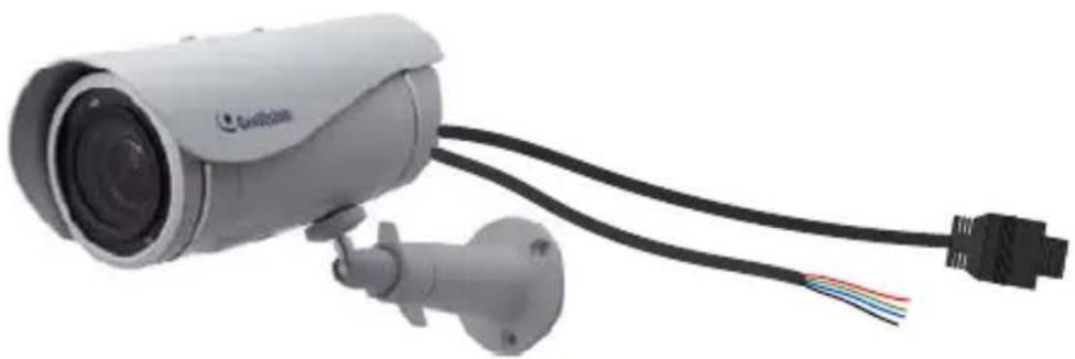
natural_image
Exterior view of a security camera with attached cable and connector (no visible text or symbols)Figure 3-13
| No. | Wire Color Definition | |
| 1 | Red DC 5V | |
| 2 | Green Digital | In |
| 3 | Blue Digital | Out |
| 4 | Black Ground |
Power Connection
Connect the camera to power using one of the following methods:
-
Use a Power over Ethernet (PoE) adapter to connect the camera to the network, and the power will be provided at the same time.
● Plug the power adaptor to the terminal block as shown below. -
Insert the black wire of the data cable to the left pin (-) and the red wire to the right pin (+).
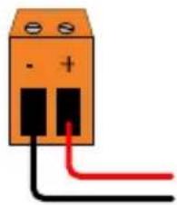
natural_image
Simple electrical component diagram with orange body, black terminals, and red/red wires (no text or symbols)Figure 3-14
- Connect the DC 5V power adapter to the terminal block.

text_image
Terminal Block DC 5V Power AdaptorFigure 3-15
Voltage Load Expansion (Optional)
The camera can only drive a maximum load of 200mA 5V DC. To expand the maximum voltage load to 10A 250V AC, 10A 125V AC or 5A 100V DC, connect the camera to a GV-Relay V2 module (optional product). Refer to the figure and table below.
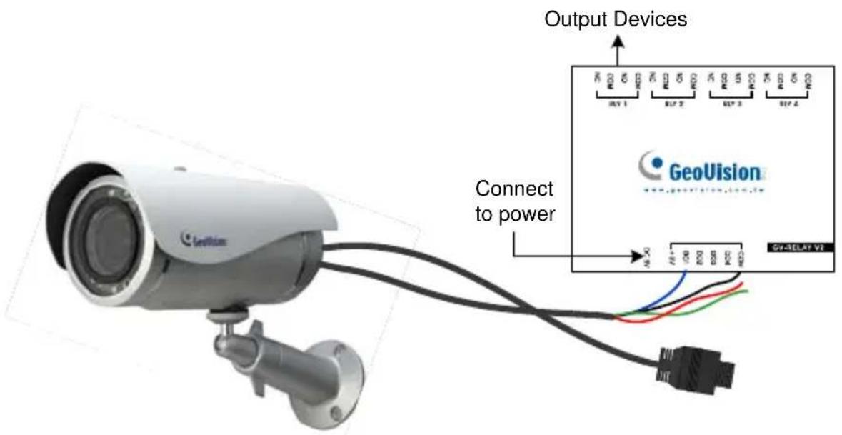
text_image
Output Devices Connect to power GeoVision V2-TELAY V2Figure 3-16
| GV-Relay V2 Ultra Bullet Camera | ||
| DO1 | Digital | Out (Blue) |
| COM | Ground | (Black) |
3.5 Loading Factory Default
- Keep the power and network cables (or PoE) connected to the camera.
- Press and hold the default button.
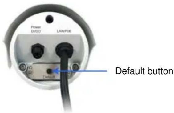
text_image
Power DiOO LAN/Fue Default buttonFigure 3-17
- Release the default button when the status LED blinks. This shall take about 8 seconds.
- When the status LED fades, the process of loading default settings is completed and the camera reboots automatically.
Chapter 4 Target Bullet Camera
The Target Bullet Camera (GV-EBL) is a series of light-weighted cameras designed for outdoor environments. The camera adheres to the IP67 standard and has full protection against dust and jets of water. The camera offers an entry-level surveillance solution with all the essential features and excellent image quality.
| Model No. | Specifications | Description | |
| GV-EBL1100-1F | Fixed Lens | Fixed Iris, f: 6 mm,F/1.8, 1/2.7” M12 Mount | 1.3 MP / 2 MP,H.264, Low Lux,D/N |
| GV-EBL2100-1F | |||
| GV-EBL1100-2F | Fixed Iris, f: 3.8 mm,F/1.8, 1/2.7” M12 Mount | ||
| GV-EBL2100-2F | |||
4.1 Packing List
- Target Bullet Camera
- Sun-Shield Cover
- Silica Gel Tape x 2
• Supporting Rack - Screw for supporting rack x 3
- Screw Anchor x 3
- Screw for sun-shield cover
- Washer
- Terminal Block
• GV-IPCAM H.264 Software DVD
• GV-NVR Software DVD - Warranty Card
Note: Power adapter can be purchased upon request.
4.2 Features
- 1/3" progressive scan low lux CMOS for GV-EBL1100 Series 1/2.8" progressive scan low lux CMOS for GV-EBL2100 Series
- Dual streams from H.264 or MJPEG
- Up to 30 fps at 1280 x 1024 Up to 25 fps at 1920 x 1080
- Intelligent IR
- Day and night function (with removable IR-cut filter)
- Wide Dynamic Range (WDR)
- Defog
• Vandal resistance (IK10 for metal casing) - Ingress protection (IP67)
- Motion detection
- Tampering alarm
- Text overlay
- Privacy mask
- IP address filtering
• DC 12V / PoE (IEEE 802.3af) - Megapixel lens
- NAS Recording
- Recording assigned by GV-Edge Recording Manager (Windows & Mac)
• Support for iPhone, iPad, Android and 3GPP
• 31 languages on Web interface
• ONVIF (Profile S) conformant
4.3 Overview
Panel
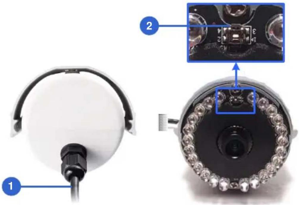
text_image
Technical diagram of a security camera with labeled components and close-up inset showing internal componentsFigure 4-1
| No. | Name Description | |
| 1 | Power Connector | Connects to the data cable. For details, see 4.5 Connecting the Camera. |
| 2 | Default Button | Resets the camera to factory default. For details, see 4.6 Loading Factory Default. |
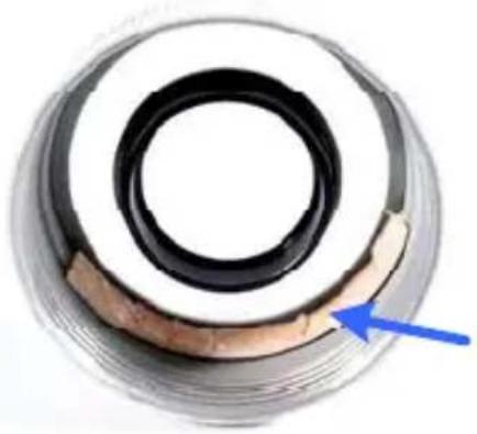
IMPORTANT: The silica gel loses its effectiveness when the camera cover is opened. If you open the camera to access the load default button, replace the silica gel tape by taping the new silica gel tape to the inside of the camera cover. Make sure you conceal the silica gel tape in the camera within two minutes of exposing to the open air.
natural_image
Close-up of a mechanical ring component with a blue arrow pointing to it (no text or symbols visible)4.4 Installation
You can install the camera to the ceiling or wall. Follow the steps below.
IMPORTANT: To avoid foggy live view, please replace Silica Gel Tape prior to installation and use waterproof tape to seal the RJ45 connector.
- Slide the sun-shield cover onto the top of the camera.
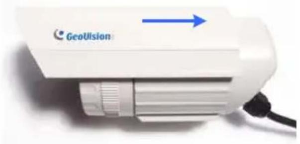
natural_image
White GeoUlsion device with blue arrow indicator, no visible text or symbols on bodyFigure 4-2
Note: The GeoVision logo on the sun-shield cover should be closer to the front of the camera.
- Line up the screw hole on the camera with the opening on the sun-shield cover.
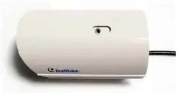
natural_image
White portable electronic device with a small circular button and 'Genelline' branding on its body (no other text or symbols visible)Figure 4-3
3. Ceiling Mount:
Secure the supporting rack to the opening on the sun-shield cover
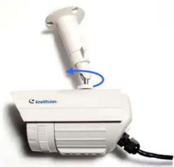
natural_image
White medical device labeled 'GepVision' with a blue arrow indicating rotation, connected to a black cable (no readable text beyond brand name)Figure 4-4
4. Wall Mount:
A. Insert and tighten the supplied screw and washer on the sun-shield cover.
B. Secure the supporting rack to the bottom.
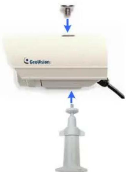
natural_image
Geovision device with blue arrow indicating force or movement, no visible text or symbols on the device itselfFigure 4-5
IMPORTANT: To avoid waterproofing failures, do not open the screw on the camera body. See Note for Waterproofing Failures.
- Install the camera to the wall or ceiling using the screw anchors and self-tapping screws. You can also stand the camera on a plain surface.
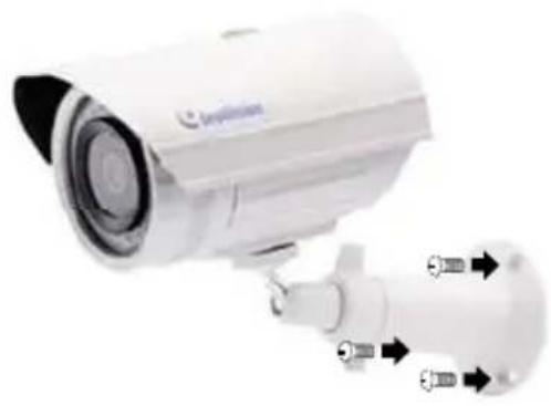
natural_image
Exterior view of a white surveillance camera with attached sensor port (no visible text or symbols)Figure 4-6
- Remove the protection sticker from the camera's cover.
- Connect the wires and cable connector to the camera. See 4.5 Connecting the Camera.
- Access the live view. For details, see 3.1. Accessing the Live View, GV-IPCam H.264 Firmware Manual.
- Adjust angles of the camera body based on the live view.
4.5 Connecting the Camera
4.5.1 Wire Definition
The data cable provides connections for power, ground and network access. The wires are defined below:
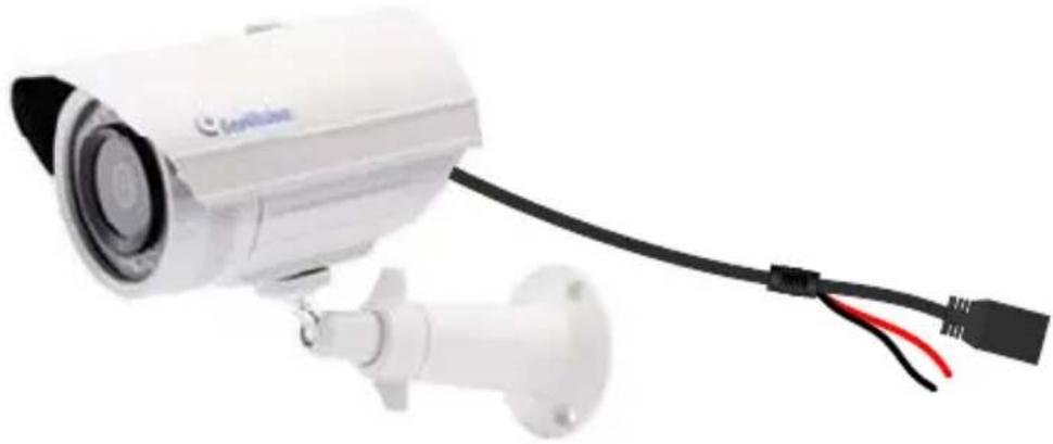
natural_image
Exterior view of a surveillance camera with attached cable and red/gray wires (no text or symbols visible)Figure 4-7
| No. | Wire Color Definition | |
| 1 | Red DC 12V | |
| 2 | Black Ground | |
| 3 | Black (thick) | PoE, Ethernet |
4.5.2 Power Connection
There are two ways to supply power to the camera:
- Use a Power over Ethernet (PoE) adapter to connect the camera to the network, and the power will be provided at the same time.
-
Plug the power adapter to the 12V terminal block as shown below. The power adapter is an optional device. For detail, see Options in the manual.
-
Insert the black wire of the data cable to the left pin (-) and the red wire to the right pin (+).
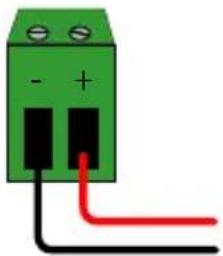
natural_image
Green electrical terminal block with two terminals and three black/red wires (no text or symbols)Figure 4-8
- Connect the DC 12V power adapter to the terminal block.

text_image
Terminal Block DC 12V Power AdaptorFigure 4-9
4.6 Loading Factory Default
- Keep the power and network cables (or PoE) connected to the camera.
- Loosen the camera's cover.
- Press and hold the default button for about 8 seconds.
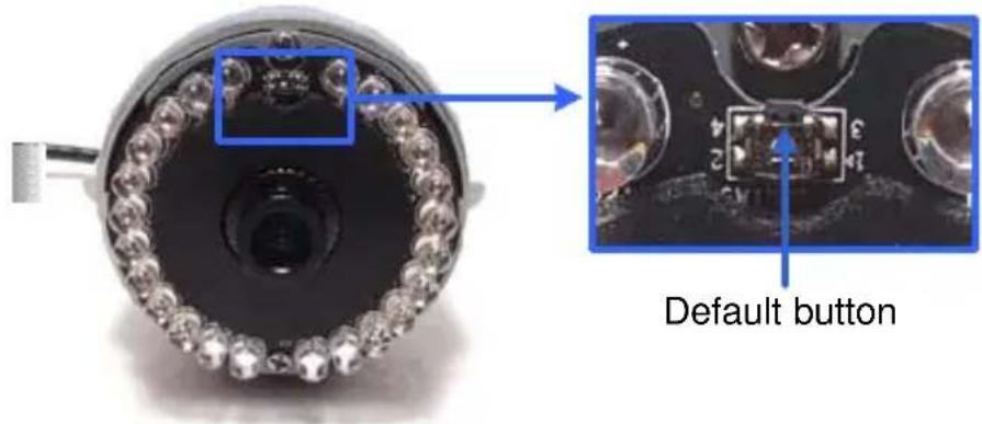
text_image
Default buttonFigure 4-10
- Release the default button. When the process of loading default settings is completed, the camera reboots automatically.
- Replace the Silica Gel Tape inside the camera cover and fasten the camera's cover immediately.