GV-BX130D-0 - Security Camera Geovision - Free user manual and instructions
Find the device manual for free GV-BX130D-0 Geovision in PDF.


User questions about GV-BX130D-0 Geovision
0 question about this device. Answer the ones you know or ask your own.
Ask a new question about this device
Download the instructions for your Security Camera in PDF format for free! Find your manual GV-BX130D-0 - Geovision and take your electronic device back in hand. On this page are published all the documents necessary for the use of your device. GV-BX130D-0 by Geovision.
USER MANUAL GV-BX130D-0 Geovision
natural_image
Exterior view of a GeoVision surveillance camera with dual lenses (no visible text or symbols on the device body)- Box Camera
- Ultra Box Camera
• Arctic Box Camera
• Target Box Camera

GeoVision
© 2015 GeoVision, Inc. All rights reserved.
Under the copyright laws, this manual may not be copied, in whole or in part, without the written consent of GeoVision.
Every effort has been made to ensure that the information in this manual is accurate. GeoVision, Inc. makes no expressed or implied warranty of any kind and assumes no responsibility for errors or omissions. No liability is assumed for incidental or consequential damages arising from the use of the information or products contained herein. Features and specifications are subject to change without notice. Note: no memory card slot or local storage function for Argentina.
GeoVision, Inc.
9F, No. 246, Sec. 1, Neihu Rd.,
Neihu District, Taipei, Taiwan
Trademarks used in this manual: GeoVision, the GeoVision logo and GV series products are trademarks of GeoVision, Inc. Windows and Windows XP are registered trademarks of Microsoft Corporation.
September 2015
Contents
Contents ......i
Options iv
Note for Installing Camera Outdoor...... vi
Note for USB Storage and WiFi Adapter ...... vii
Chapter 1 Box Camera ....1
1.1 Packing List....5
1.2 Features....6
1.2.1 Wide Dynamic Range Pro....9
1.3 Overview....10
1.3.1 GV-BX120D / 130D Series / 140DW / 220D Series / 320D Series / 520D ....10
1.3.2 GV-BX1200 Series / 1300 Series / 1500 Series / 2400 Series / 2500 Series / 2600 / 3400 Series / 5300 Series / 12201 ....12
1.4 Connecting the Camera....15
1.4.1 GV-BX120D / 130D Series / 140DW / 220D Series / 320D Series / 520D ....15
1.4.2 GV-BX1200 Series / 1300 Series / 1500 Series / 2400 Series / 2500 Series / 2600 / 3400 Series / 5300 Series / 12201 ....17
1.5 Accessory Installation....19
1.5.1 C-Mount Lenses....19
1.5.2 Infrared Illuminators (Optional) 20
1.6 I/O Terminal Block....21
1.6.1 Pin Assignment....21
1.6.2 Connecting to GV-Relay V2 (Optional)....22
1.7 Loading Factory Default....23
Chapter 2 IR Arctic Box Camera ....24
2.1 Packing List....26
2.2 Features....28
2.3 Overview ....30
2.3.1 GV-BX120D-E / 220D-E / 320D-E / 520D-E / 1500-E /
2400-E / 3400-E / 5300-E ....30
2.3.2 GV-BX2510-E / 5310-E....31
2.4 Installation....32
2.5 Connecting the Camera....38
2.5.1 GV-BX120D-E / 220D-E / 320D-E / 520D-E / 1500-E /
2400-E / 3400-E / 5300-E ....38
2.5.2 GV-BX2510-E / 5310-E....40
2.6 Notice for Using the IR Arctic Box Camera ....43
2.6.1 Enabling IR LED after Loading Default....44
2.6.2 Disabling Status LED under Low Light Conditions.....45
2.7 Loading Factory Default....46
Chapter 3 Ultra Box Camera....47
3.1 Packing List....48
3.2 Features....49
3.3 Overview ....50
3.4 Installation....51
3.5 Connecting the Camera....53
3.6 Loading Factory Default ....54
Chapter 4 Target Box Camera ....55
4.1 Packing List....55
4.2 Features....56
4.3 Overview....57
4.4 Installation....58
4.5 Connecting the Camera....60
4.6 Loading Factory Default....61
Appendix....62
A. Supported Lenses for Box Camera....62
Options
Optional devices can expand your camera's capabilities and versatility.
Contact your dealer for more information.
| Device Description | |
| Power Adapter | The power adapter is available for all Box Camera, Ultra Box Camera, and Target Box Camera. Contact your sales representative for the countries and areas supported. |
| GV-PA191 PoE Adapter | The GV-PA191 PoE adapter is designed to provide power and network connection to the cameras over a single Ethernet cable. |
| GV-PA481 PoE Adapter | The GV-PA481 PoE adapter is designed to provide power and network connection to GV-BX1500-E / 2400-E / 3400-E / 5300-E over a single Ethernet cable. |
| GV-PA482 PoE Adapter | The GV-PA481 PoE adapter is designed to provide power and network connection to GV-BX2510-E / 5310-E over a single Ethernet cable. |
| GV-POE Switch | The GV-POE Switch is designed to provide power along with network connection for IP devices. The GV-POE Switch is available in various models with different numbers and types of ports. |
| GV-Mount Accessories | The GV-Mount Accessories provide a comprehensive lineup of accessories for installation on ceiling, wall corner and pole. For details, see GV-Mount Accessories Installation Guide on the Software DVD. |
| GV-WiFi Adapter | The GV-WiFi Adapter is a plug-and-play device designed to connect GV-BX1200 Series / 1300 series / 1500 series / 2400 series / 2500 series / 3400 series / 5300 series and GV-MFD1501 series / 2401 series / 2501 series / 3401 series / 5301 series to wireless network. This product complies with IEEE 802.11 b/g/n (Draft 3.0) standards for wireless networking. |
| GV-Relay V2 | The GV-Relay V2 is designed to expand the voltage load of GV IP devices. It provides 4 relay outputs, and each can be set as normally open (NO) or normally closed (NC) independently as per your requirement. |
Note for Installing Camera Outdoor
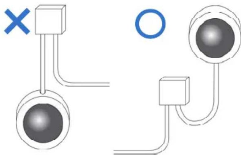
When installing the IR Arctic Box Camera outdoor, be sure that:
- The camera is set up above the junction box to prevent water from entering the camera along the cables.
natural_image
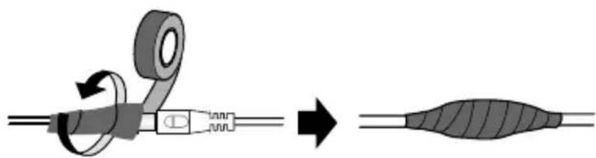
Diagram showing two connected components with a cross mark and a circle, no text or symbols present- Any PoE, power, audio and I/O cables are waterproofed using waterproof silicon rubber or the like.
natural_image
Diagram showing a mechanical assembly with rotating components and a final elongated structure (no text or symbols)- The silica gel bag loses its effectiveness when the dry camera is opened. To prevent the lens from fogging up, replace the silica gel bag every time you open the camera, and conceal the gel bag in camera within 2 minutes of exposing to open air.
Note for USB Storage and WiFi Adapter
Mind the following limitations and requirements for using USB storage and GV-WiFi Adapter:
- The USB hard drive must be of 2.5" or 3.5", version 2.0 or above.
- The USB hard drive's storage capacity must not exceed 2TB.
- USB flash drives and USB hubs are not supported.
- External power supply is required for the USB hard drive.
- To connect a GV-WiFi Adapter, make sure it is connected before the camera is powered on.
Chapter 1 Box Camera
The Box Camera is a series of indoor IP cameras consisting of fixed focal and varifocal models in different resolutions. The Box Camera supports lens replacement and features an automatic infrared-cut filter for day and night surveillance. The super low lux models are capable of displaying color live view in near darkness. Models equipped with a mini USB port can be connected wirelessly through a GV-WiFi Adapter (optional). The WDR Pro models can produce clear image for scenes with contrasting intensity of lights (see 1.2.1 Wide Dynamic Range Pro for details). Models using P-Iris allow for precise control of exposure, producing images with better clarity and contrast. For details on related models, see 1.2 Features. The Box Camera models are detailed below:
Box Camera
| Model No. | Specifications | Description | |
| GV-BX120D | Varifocal Lens | Auto Iris, f:2.8 ~ 12 mm, F/1.4, 1/3” CS Lens | 1.3 MP, H.264, Low Lux, D/N |
| GV-BX130D-0 | Auto Iris, f: 2.8 ~ 12 mm, F/1.4, 1/3” CS Lens | 1.3 MP, H.264, D/N | |
| GV-BX130D-1 | Fixed Lens | Fixed Iris, f: 4 mm, F/1.4, 1/3” CS Lens | 1.3 MP, H.264, D/N |
| GV-BX140DW | Varifocal Lens | Fixed Iris, f: 2.8 ~ 12 mm, F/1.4, 1/3” CS Lens | 1 MP, H.264, D/N, WDR Pro |
| GV-BX220D-2 | Auto Iris, f: 2.8 ~ 6 mm, F/1.3, 1/3” CS Lens | 2 MP, H.264, D/N | |
| Model No. Specifications Description | |||
| GV-BX220D-3 | Varifocal Lens | Auto Iris, f: 2.8 ~ 12 mm, F/1.4, 1/3" CS Lens | 2 MP, H.264, D/N |
| GV-BX320D-0 | Varifocal Lens | Auto Iris, f:3.1 ~ 8 mm, F/1.2, 1/3" CS Lens | 3 MP, H.264, D/N |
| GV-BX320D-1 | Auto Iris, f: 2.8 ~ 6 mm, F/1.3, 1/3" CS Lens | ||
| GV-BX520D | Manual Iris, f: 4.5 ~ 10 mm, F/1.6, 1/2" CS Lens | 5 MP, H.264, D/N | |
| GV-BX1200-0F | Fixed Lens | Fixed Iris, f: 4 mm, F/1.5, 1/3" CS Lens | 1.3 MP, H.264, Low Lux, D/N |
| GV-BX1300-0F | 1.3 MP, H.264, D/N | ||
| GV-BX1200-1F | Fixed Lens | Fixed Iris, f: 8 mm, F/1.6, 1/2.5" CS Lens | 1.3 MP, H.264, Low Lux, D/N |
| GV-BX1300-1F | 1.3 MP, H.264, D/N | ||
| GV-BX1500-1F | 1.3 MP, H.264, Super Low Lux, D/N | ||
| GV-BX2400-1F | 2 MP, H.264, D/N, WDR Pro | ||
| GV-BX2500-1F | 2 MP, H.264, Super Low Lux, D/N | ||
| GV-BX3400-1F | 3 MP, H.264, D/N, WDR Pro | ||
| GV-BX1200-2F | Fixed Lens | Fixed Iris, f: 12 mm, F/1.6, 1/2.5" CS Lens | 1.3 MP, H.264, Low Lux, D/N |
| GV-BX1300-2F | 1.3 MP, H.264, D/N | ||
| GV-BX1500-2F | 1.3 MP, H.264, Super Low Lux, D/N | ||
| GV-BX2400-2F | 2 MP, H.264, D/N, WDR Pro | ||
| GV-BX2500-2F | 2 MP, H.264, Super Low Lux, D/N | ||
| GV-BX3400-2F | 3 MP, H.264, D/N, WDR Pro | ||
| GV-BX1200-3V | Varifocal Lens | Auto Iris, f:2.8 ~ 12 mm, F/1.4, 1/2.7" CS Lens | 1.3 MP, H.264, Low Lux, D/N |
| GV-BX1300-3V | 1.3 MP, H.264, D/N | ||
| GV-BX1500-3V | 1.3 MP, H.264, Super Low Lux, D/N | ||
| GV-BX2500-3V | 2 MP, H.264, Super Low Lux, D/N | ||
| GV-BX2600 | Auto Iris, f:3 ~ 10.5 mm, F/1.4, 1/2.7" CS Lens | 2 MP, H.264, Super Low Lux, D/N, WDR Pro | |
| GV-BX3400-5V | Auto Iris, f: 2.8 ~ 6 mm, F/1.3, 1/3" CS Lens | 3 MP, H.264, D/N, WDR Pro | |
| GV-BX5300-6V | Manual Iris, f: 4.5 ~ 10 mm, F/1.6, 1/2” CS Lens | 5 MP, H.264, D/N | |
| GV-BX1500-8F | Fixed Lens | Fixed Iris, f: 2.8 mm, F/1.8, 1/2.5” CS Lens | 1.3 MP, H.264, Super Low Lux, D/N |
| GV-BX2500-8F | 2 MP, H.264, Super Low Lux, D/N | ||
| GV-BX3400-8F | 3 MP, H.264, D/N, WDR Pro | ||
| GV-BX5300-8F | 5 MP, H.264, D/N | ||
| GV-BX12201 | Varifocal Lens | DC drive Iris, f: 4.1 ~ 9 mm, F/1.6, 1/1.8” CS Lens | 12 MP, H.264, D/N |
P-Iris Models (Coming)
| Model No. Specifications Description | |||
| GV-BX1500-3V | Varifocal Lens | P-Iris, f: 3 ~ 10.5 mm, F/1.4, 1/2.7" CS Lens | 1.3 MP, H.264, Super Low Lux, D/N |
| GV-BX2500-3V | 2 MP, H.264, Super Low Lux, D/N | ||
| GV-BX3400-3V | 3 MP, H.264, D/N, WDR Pro | ||
| GV-BX5300-6V | P-Iris, f: 3.3 ~ 10.5 mm, F/1.4, 1/2.5" CS Lens | 5 MP, H.264, D/N | |
1.1 Packing List
- Box Camera
- Terminal Block
- Fixed Focal or Varifocal Megapixel Lens
- Six Lens Rings
• One 0.125 mm Lens Ring (for GV-BX140DW only) - Video Out Wire
- Camera Holder
- Holder Screw x 2
- Power Adapter
• GV-IPCAM H.264 Software DVD
• GV-NVR Software DVD - Warranty Card
Note: The power adapter can be excluded upon request.
1.2 Features
- Image sensor
| Camera Model Image Sensor | |
| GV-BX120DGV-BX1200 Series | 1/3” progressive scan low lux CMOS |
| GV-BX130D SeriesGV-BX1300 SeriesGV-BX220D SeriesGV-BX320D SeriesGV-BX520DGV-BX5300 Series | 1/2.5” progressive scan CMOS |
| GV-BX140DW 1/3” | progressive scan CMOS |
| GV-BX1500 Series 1/3” | progressive scan super low lux CMOS |
| GV-BX2500 SeriesGV-BX2600 | 1/2.8” progressive scan super low lux CMOS |
| GV-BX2400 SeriesGV-BX3400 Series | 1/3.2” progressive scan CMOS |
| GV-BX12201 1/1.7” | progressive scan CMOS |
- Frame Rate
| Camera Model Frame Rate | |
| GV-BX120D | Up to 30 fps at 1280 x 1024 |
| GV-BX130D Series | |
| GV-BX1200 Series | |
| GV-BX1300 Series | |
| GV-BX1500 Series | |
| GV-BX140DW Up to 30 fps at 1280 x 720 | |
| GV-BX220D Series | Up to 30 fps at 1920 x 1080 |
| GV-BX2400 Series | |
| GV-BX2500 Series | |
| GV-BX2600 | |
| GV-BX320D Series | Up to 20 fps at 2048 x 1536 |
| GV-BX3400 Series | |
| GV-BX520D | Up to 10 fps at 2560 x 1920 |
| GV-BX5300 Series | |
| GV-BX12201 | Up to 15 fps at 4000 x 3000Up to 30 fps at 3840 x 2160 |
- Dual streams from H.264 or MJPEG
• Day / Night function (with removable IR-cut filter) - Wide Dynamic Range Pro (GV-BX140DW / 2400 Series / 2500 Series / 2600 / 3400 Series only)
- P-Iris for auto iris adjustment (Coming, for GV-BX1500-3V / 2500-3V / 3400-3V / 5300-6V only)
- Defog
- Two-way audio
• One sensor input and alarm output - TV-out support
-
Micro SD card slot (SD/SDHC) for local storage
• NAS recording (for Box Camera using firmware V3.0 or later) -
Recording assigned by GV-Edge Recording Manager (Windows & Mac) for Box Camera using firmware V3.0 or later
- Mini USB slot for WiFi Adapter or a USB hard drive (for GV-BX1200 Series / 1300 Series / 1500 Series / 2400 Series / 2500 Series / 2600 / 3400 Series / 5300 Series only)
• 3D noise reduction (for GV-BX1500 Series / 2500 Series / 2600)
• 2D noise reduction (except GV-BX1500 Series / 2500 Series / 2600) - Motion detection
- Tampering alarm
- Visual automation
- Privacy mask
- Text overlay
• Video Analysis (GV-BX2600 only) - IP address filtering
• DC 12V and PoE (IEEE 802.3af) - Megapixel lens
• Support for iPhone, iPad, Android and 3GPP
• 31 languages on Web interface
• ONVIF (Profile S) conformant
Note: BX12201 does not support the memory card and external USB hard drive for local storage.
1.2.1 Wide Dynamic Range Pro
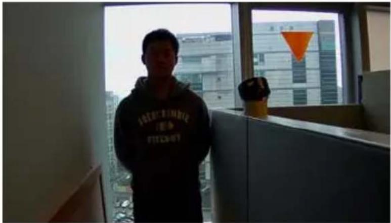
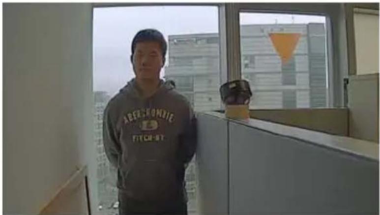
Objects may appear as silhouettes when they are backed with intense lights. The Wide Dynamic Range Pro (WDR Pro) is designed to solve this problem using a WDR sensor. In GV-BX140DW, GV-BX2400 Series, GV-BX2600 and GV-BX3400 Series, the WDR sensor is able to process the image and show details in bright and dark areas at the same time. An example of WDR Pro in action is shown below.
No WDR: underexposure
natural_image
Interior view of a modern office with a person standing near a window overlooking a cityscape (no visible text or symbols)WDR: perfect exposure
natural_image
Man standing in an office with a window overlooking a cityscape (no visible text or symbols)For GV-IPCam H.264 models that support WDR, the WDR effect is achieved through software programming.
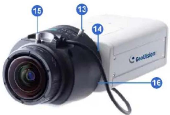
1.3 Overview
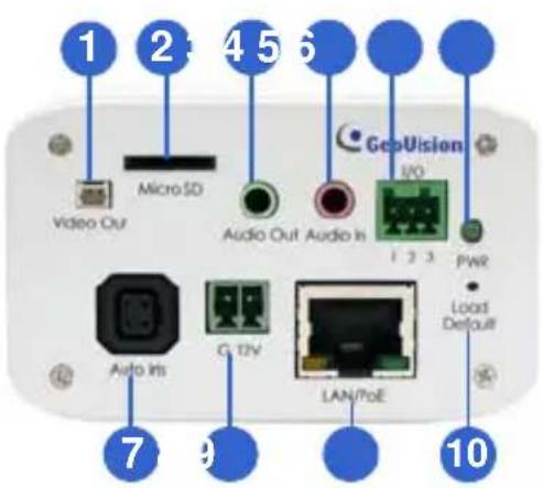
1.3.1 GV-BX120D / 130D Series / 140DW / 220D Series / 320D Series / 520D
text_image
1 2 4 5 6 Video Out Micro SD Audio Out Audio In GepVision I/O 1 2 3 PWR Load Default Auto Ins G 12V LAN/7oE 7 9 10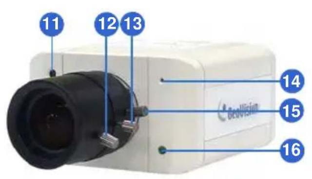
text_image
11 12 13 14 15 16Figure 1-1
Note:
- The Auto Iris connector (No. 7) is only functional in GV-BX120D, GV-BX130D-0, GV-BX220D and GV-BX320D.
- The Light Sensor (No.11) is only available in GV-BX140DW. Keep the Light Sensor unobscured for accurate light detection.
- The Iris Screw (No.13) is only available for GV-BX520D.
- The Zoom Screw (No. 15) is not available for GV-BX130D-1.
| No. | Name Description | |
| 1 | Video Out | Connects to a portable monitor for setting the focus and angle of Box Camera during initial installation. |
| 2 | Memory Card Slot | Inserts a micro SD card (SD/SDHC, version 2.0 only, Class 10) to store recording data. |
| 3 | Audio Out Connects | a speaker for audio output. |
| 4 | Audio In Connects a | microphone for audio input. |
| 5 | I/O Terminal Block | For details, see 1.6 I/O Terminal Block. |
| 6 | Power LED | Indicates the power is supplied. For detail, see the table below. |
| 7 | Auto Iris Connector | Plug the iris control cable to the connector. |
| 8 | DC 12V Port Connects to power. | |
| 9 | LAN / PoE Connects to a 10/100 Ethernet or PoE. | |
| 10 | Default | Restores the camera to the factory default. For details, see 1.7 Loading Factory Default. |
| 11 | Light Sensor | Detects light to switch between day and night mode. |
| 12 | Focus Screw Adjusts the focus of the camera. | |
| 13 | Iris Screw Adjusts the iris of the camera. | |
| 14 | Microphone Records the sounds. | |
| 15 | Zoom Screw Adjusts the zoom of the camera. | |
| 16 | Status LED | Turns on when the unit is ready for use. For detail, see the table below. |
| LED | Description |
| Power LED turns green | The system powers on and succeeds to boot up. |
| Status LED turns green | The system is ready for use. |
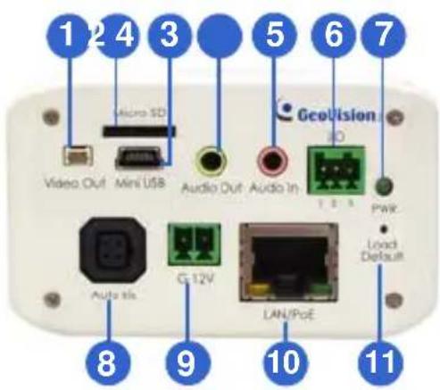
1.3.2 GV-BX1200 Series / 1300 Series / 1500 Series / 2400 Series / 2500 Series / 2600 / 3400 Series / 5300 Series / 12201
text_image
1 2 4 3 Video Out Mini USB Audio Out Audio In GEOVision Auto tis G 12V LAN/PoE PWR Load Default 8 9 10 11Figure 1-2-1
text_image
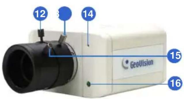
12 3 14 GeoVision 15 16Figure 1-2-2:
GV-BX1200 Series / 1300 Series / 1500
Series / 2400 Series / 2500 Series / 2600
/ 3400 Series / 5300 Series
text_image
15 13 14 GeoUlsian 16Figure 1-2-1:
GV-BX12201
Note:
- The Auto Iris Connector (No. 8) is only functional for varifocal models of GV-BX1200 / 1300 / 1500 / 2400 / 2500 / 2600 / 3400.
- The Iris Screw (No. 12) is only available in GV-BX5300-6V.
- The Zoom Screw (No. 13) is only available for varifocal models of GV-BX1200 / 1300 / 1500 / 2400 / 2500 / 2600 / 3400 / 5300 / 12201.
- The Memory Card Slot (No. 2) is currently not supported for GV-BX12201.
- Mini USB Slot (No. 3) connected to USB hard drive is currently not supported for GV-BX12201.
- Built-in microphone is not available for GV-BX2600.
| No. | Name Description | |
| 1 | Video Out | Connects to a portable monitor for setting the focus and angle of Box Camera during initial installation. |
| 2 | Memory Card Slot | Inserts a micro SD card (SD/SDHC, version 2.0 only, Class 10) to store recording data. |
| 3 | Mini USB | Connects to a GV-WiFi Adapter or a USB Slot hard drive. |
| 4 | Audio Out Connects a speaker for audio output. | |
| 5 | Audio In Connects a microphone for audio input. | |
| 6 | I/O Terminal Block | Connects to I/O devices. For details, see 1.6 I/O Terminal Block. |
| 7 | Power LED | Indicates the power is supplied. For detail, see the table below. |
| 8 | Auto Iris Connector | Plug the iris control cable to the connector. |
| 9 | DC 12V Port Connects to power. | |
| 10 | LAN / PoE Connects to a 10/100 Ethernet or PoE. | |
| 11 | Default | Restores the camera to factory default. For details, see 1.7 Loading Factory Default. |
| 12 | Iris Screw Adjusts the iris of the camera. | |
| 13 | Zoom Screw Adjusts the zoom of the camera. | |
| 14 | Microphone Records the sounds. | |
| 15 | Focus Screw Adjusts the focus of the camera. | |
| 16 | Status LED | Turns on when the unit is ready for use. For detail, see the table below. |
| LED Description | |
| Power LED turns green | The system powers on and succeeds to boot up. |
| Status LED turns green | The system is ready for use. |
1.4 Connecting the Camera
The Box Camera is designed for indoor use. Please make sure the installing site is shielded from rain and moisture.
1.4.1 GV-BX120D / 130D Series / 140DW / 220D Series / 320D Series / 520D
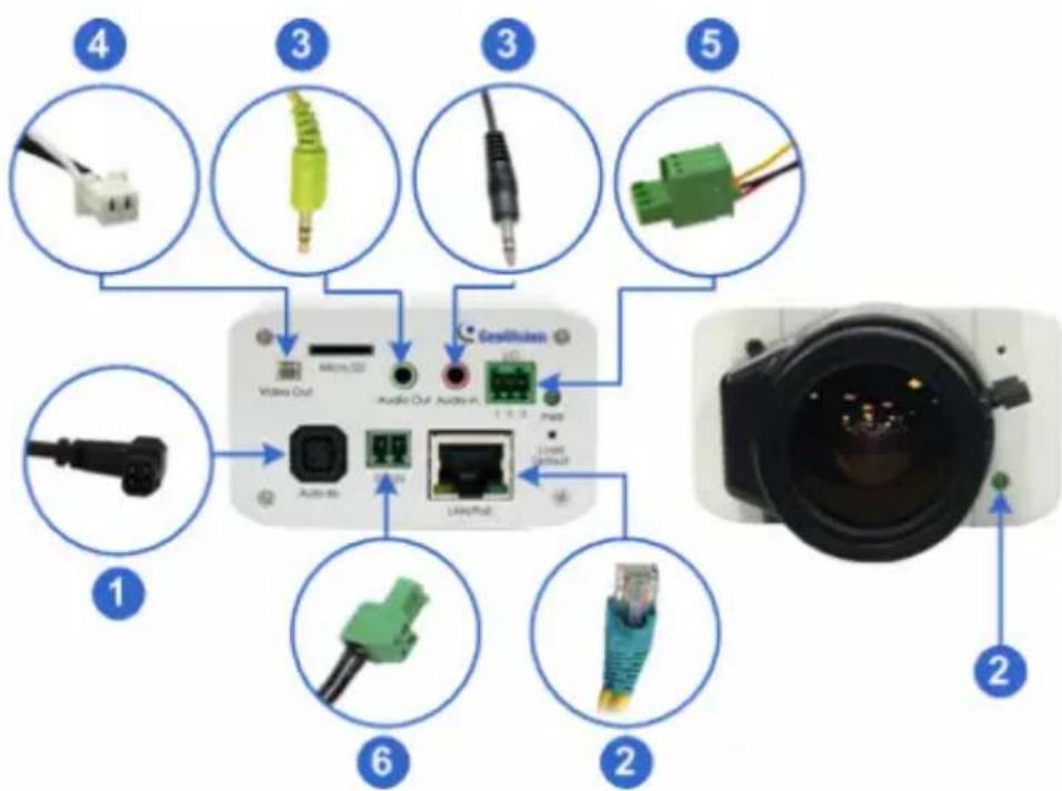
text_image
1 2 3 4 5 6 7 8 9 10 11 12 13 14 15 16 17 18 19 20 Video Out Audio Out Audio in Laser/Max Gesellsuit Line LineoutFigure 1-3
- If you are using an auto iris model, plug the iris control cable to the Auto Iris Connector on the camera.
- Use a standard network cable to connect the camera to your network.
- Optionally connect a speaker and an external microphone.
- Optionally connect a monitor using a Video Out wire. Enable this function by selecting your signal format at the TV Out field on the Web interface. See 4.1.1 Video Settings, GV-IPCam H.264 Firmware Manual.
GeoVision
-
Optionally connect to input / output devices or an infrared illuminator. For details, see 1.5.2 Infrared Illuminator and 1.6 I/O Terminal Block.
-
Connect power using one of the following methods:
- plugging the power adapter to the power port.
- using the Power over Ethernet (PoE) function and the power will be provided over the network cable.
-
The status LED of the camera will be on.
-
You are ready to access the live view, adjust the image clarity and configure the basics. See Getting Started, Chapter 2, GV-IPCam H.264 Firmware Manual.
1.4.2 GV-BX1200 Series / 1300 Series / 1500 Series / 2400 Series / 2500 Series / 2600 / 3400 Series / 5300 Series / 12201
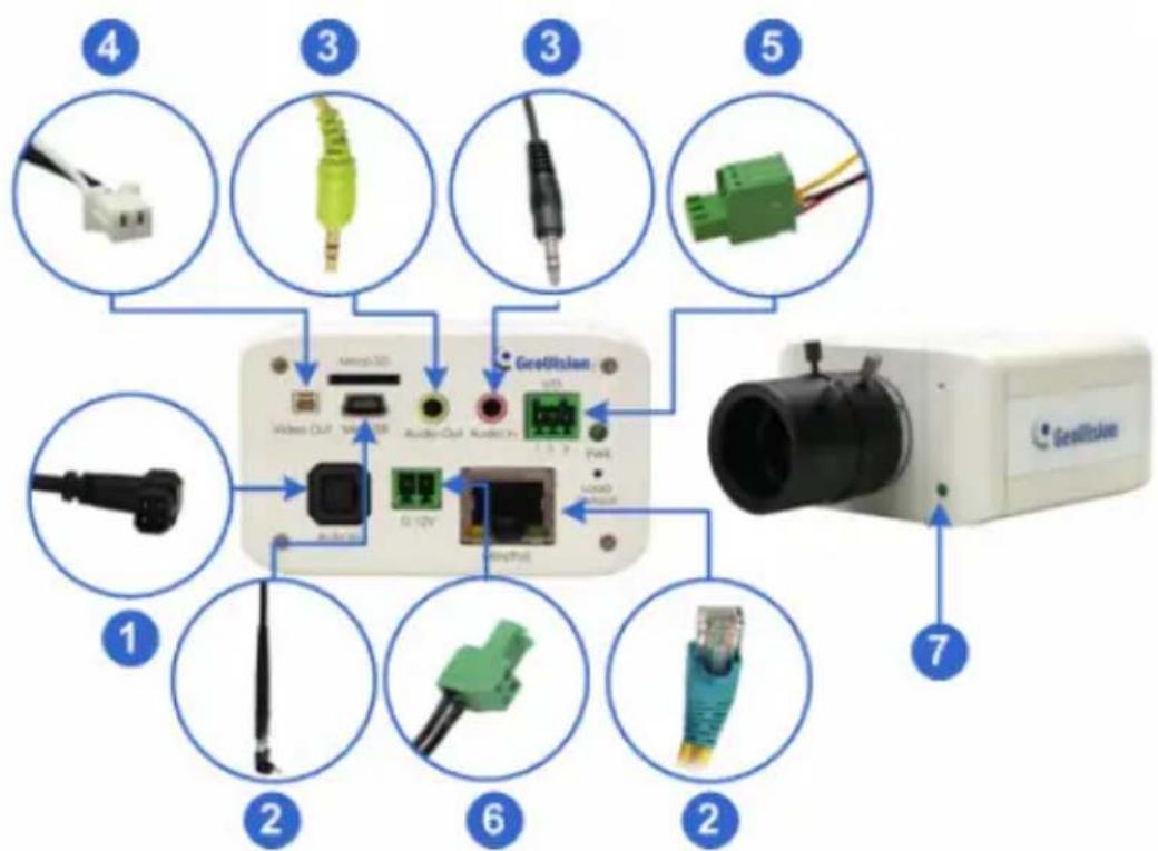
text_image
4 3 3 5 1 2 6 2 7 GeoQIIOSAN GeoQIIOSANFigure 1-4
- If you are using an auto iris model, plug the iris control cable to the Auto Iris Connector on the camera.
- Connect to network using one of the following methods:
- Wired Connection: Use a standard network cable to connect the camera to your network and optionally connect a USB hard drive to the mini USB port.
- Wireless Connection: Connect a GV-WiFi Adapter (optional accessory).
-
Optionally connect a speaker and an external microphone.
-
Optionally connect a monitor using a Video Out wire. Enable this function by selecting your signal format at the TV Out field on the Web interface. See 4.1.1 Video Settings, GV-IPCam H.264 Firmware Manual.
- Optionally connect to input / output devices or an infrared illuminator. For details, see 1.5.2 Infrared Illuminator and 1.6 I/O Terminal Block.
- Connect power using one of the following methods:
- plugging the power adapter to the power port.
- using the Power over Ethernet (PoE) function and the power will be provided over the network cable.
- The status LED of the camera will be on.
- You are ready to access the live view, adjust the image clarity and configure the basics. See Getting Started, Chapter 19, GV-IPCam H.264 Firmware Manual.
Note: For details on limitations and requirements of the mini USB port, refer to the Note for USB Storage and WiFi Adapter at the beginning of this manual.
1.5 Accessory Installation
1.5.1 C-Mount Lenses
If you use a C-mount lens, it requires a certain distance from the camera's imaging chip to focus the lens. Mount the supplied C-mount lens adapter / lens ring to the camera, and then secure the lens onto the camera body.
Three types of C-mount lens rings are provided for Box Camera:
- 0.188 mm (transparent color) x 2
- 0.125 mm (black color with a glossy surface) x 2
- 0.254 mm (black color with a matt surface) x 2
For GV-BX140DW, a 0.125 mm is provided.
Note: The C-mount lens rings are specially designed for Box Camera. Besides the supplied C-mount lens rings, each of these models has already included with the necessary lens ring.
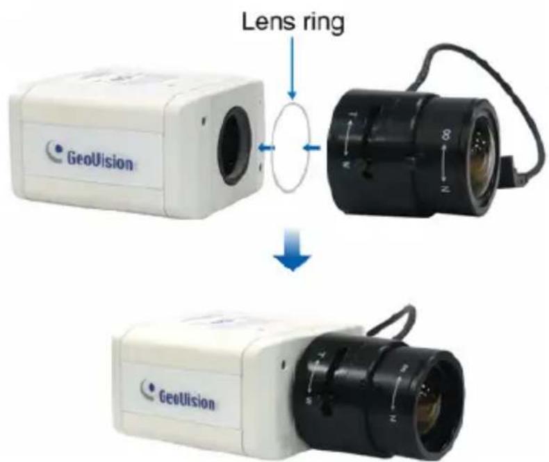
text_image
Lens ring GeoVision GeoVisionFigure 1-5
1.5.2 Infrared Illuminators (Optional)
If you use an infrared (IR) illuminator with I/O function, follow the steps below to install it.
- Connect the infrared illuminator to the terminal block on the camera. See 1.6 The I/O Terminal Block.
- Access the Web interface of the camera.
- Select Video and Motion, select Video Settings, select Streaming 1 and set the IR Check Function setting to Trigger by Input.
- Click Apply.
For details on the Trigger by Input function, see 4.1.1 Video Settings, GV-IPCam H.264 Firmware Manual.
1.6 I/O Terminal Block
The terminal block, located on the back panel of the Box Camera, provides the interface to one input and one output devices. The I/O terminal block can be used for applications such as motion detection, event alerts via E-Mail and FTP, and center monitoring through Center V2 and VSM.
1.6.1 Pin Assignment
The pin assignment for the I/O terminal block:
For the output point, please check if your output device meets the following Absolute Maximum Ratings before connecting it to the output point.
| Breakdown Voltage 277V AC, 30V DC | |
| Continuous Load Current 5A (NO), 3A (NC) | |
| Note: Absolute Maximum Ratings are those values beyond which damage to the camera may occur. Continuous operation of the camera at the absolute rating level may affect the camera reliability. |
The Box Camera support one digital input and one digital output of dry contact.
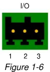
text_image
I/O 1 2 3 Figure 1-6| Pin Function | ||
| 1 | Digital | Input |
| 2 | GND | |
| 3 | Digital | Output |
For details on how to enable an installed I/O device, see 4.2 I/O Settings, GV-IPCam H.264 Firmware Manual.
1.6.2 Connecting to GV-Relay V2 (Optional)
The Box Camera can only drive a maximum load of 200mA 5V DC. To expand the maximum voltage load to 10A 250V AC, 10A 125V AC or 5A 100V DC, connect the camera to a GV-Relay V2 module (optional product). Refer to the figure and table below.
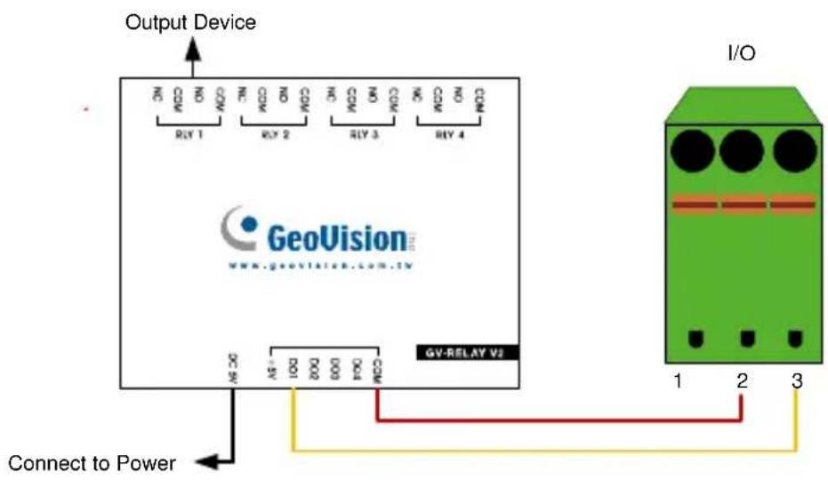
text_image
Output Device ON ON ON ON ON ON ON ON ON ON ON ON ON ON ON ON ON ON ON ON ON ON ON ON ON ON ON ON ON ON ON ON ON ON ON ON ON ON ON ON ON ON ON ON ON ON ON ON ON ON ON ON ON ON ON ON ON ON ON ON ON ON ON ON ON ON ON ON ON ON ON ON ON ON ON ON ON ON ON ON ON ON ON ON ON ON ON ON ON ON ON ON ON ON ON ON ON ON ON ON ON OR GeoVision www.geovision.com.tv GV-RELAY V2 Connect to Power 1 2 3 I/OFigure 1-7
| GV-Relay V2 I/O Terminal Block | |
| COM Pin 2 (GND) | |
| DO1 Pin 3 (Digital Output) |
1.7 Loading Factory Default
-
Keep the power and network cables connected to the camera.
-
Use a pin to press and hold the default button on the back panel of the camera.
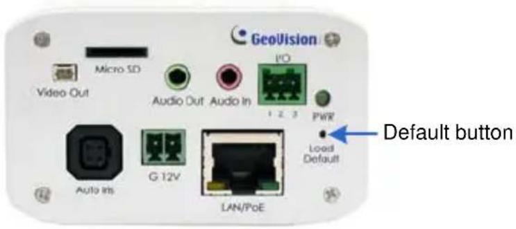
text_image
GeoVision Micro SD Video Out Audio Out Audio In I/O 1 2 3 PWR Default button Load Default Auto Ins G 12V LAN/PoEFigure 1-8
- Release the default button when the status LED blinks. This shall take about 8 seconds.
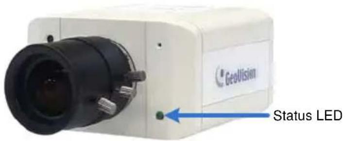
text_image
GeoVision Status LEDFigure 1-9
- When the status LED fades, the process of loading default settings is completed and the camera reboots automatically.
Chapter 2 IR Arctic Box Camera
The IR Arctic Box Camera is a series of outdoor cameras designed for environments of extreme temperatures. The cameras adhere to IP67 and IK10 protection standards, and are equipped with IR LEDs and removable IR-cut filter for day and night surveillance. The GV-BX2400-E / 3400-E are equipped with WDR Pro to produce clear image for scenes containing contrasting intensity of lights (see 2.2.1 Wide Dynamic Range Pro for details). Models using P-Iris allow for precise control of exposure, producing images with better clarity and contrast.
IR Arctic Box Camera
| Model No. | Specifications | Description | |
| GV-BX120D-E | Varifocal Lens | Auto Iris, f: 2.8 ~ 12 mm, F/1.4, 1/3" CS Lens | 1.3 MP, H.264, Low Lux, D/N |
| GV-BX220D-E | Auto Iris, f: 2.8 ~ 6 mm, F/1.3, 1/3" CS Lens | 2 MP, H.264, D/N | |
| GV-BX320D-E | Auto Iris, f: 2.8 ~ 6 mm, F/1.3, 1/3" CS Lens | 3 MP, H.264, D/N | |
| GV-BX520D-E | Manual Iris, f: 4.5 ~ 10 mm, F/1.6, 1/2" CS Lens | 5 MP, H.264, D/N | |
| GV-BX1500-E | Auto Iris, f: 3 ~ 10.5 mm, F/1.4, 1/2.7" CS Lens | 1.3 MP, H.264, Super Low Lux, D/N | |
| GV-BX2400-E GV-BX3400-E | Auto Iris, f: 3 ~ 10.5 mm, F/1.4, 1/2.7" CS Lens | 2 MP / 3 MP, H.264, D/N, WDR Pro | |
| GV-BX5300-E | Manual Iris, f: 4.5 ~ 10 mm, F/1.6, 1/2" CS Lens | 5 MP, H.264 D/N | |
| GV-BX2510-E | Motorized Varifocal Lens | P-Iris, f: 3.7 ~ 9 mm, F/1.2, 1/2”, ø 14 mm mount | 2 MP, H.264, Super Low Lux, D/N |
| GV-BX5310-E | P-Iris, f: 4.5 ~ 9 mm, F/1.2, 1/2”, ø 14 mm mount | 5 MP, H.264 D/N | |
2.1 Packing List
For GV-BX120D-E / 220D-E / 320D-E / 520D-E / 1500-E / 2400-E / 3400-E / 5300-E
- IR Arctic Box Camera
- Screw Anchor x 4
- Screw x 4
- Washer x 4
- 4 mm Torx Wrench
- 5 mm Torx Wrench
- Silica Gel Bag x 2
• Adhesive Tape for Silica Gel Bag x 2
• GV-IPCAM H.264 Software DVD
• GV-NVR Software DVD - Warranty Card
Note: Optionally purchase a GV-PA481 PoE Adapter for GV-BX1500-E / 2400-E / 3400-E / 5300-E.
For GV-BX2510-E / 5310-E
- IR Arctic Box Camera
- Screw Anchor x 4
- Screw x 4
- Washer x 4
- 5 mm Torx Wrench
- Silica Gel Bag
• Adhesive Tape for Silica Gel Bag
• Power Adapter (DC 48V, 2.5A, 120 W max.)
• GV-IPCAM H.264 Software DVD
• GV-NVR Software DVD - Warranty Card
Note: Optionally purchase a GV-PA482 PoE Adapter for GV-BX2510-E / 5310-E.
2.2 Features
- Image sensor
| Camera Model | Image Sensor |
| GV-BX120D-E | 1/3" progressive scan low lux CMOS |
| GV-BX1500-E | 1/3" progressive scan super low lux CMOS |
| GV-BX220D-EGV-BX320D-EGV-BX520D-EGV-BX5300-E | 1/3.2" progressive scan CMOS |
| GV-BX2510-E | 1/2.8" progressive scan super low lux CMOS |
| GV-BX2400-EGV-BX3400-EGV-BX5310-E | 1/2.5" progressive scan CMOS |
• Dual streams from H.264 or MJPEG
- Frame rate:
| Camera Model | Frame Rate |
| GV-BX120D-EGV-BX1500-E | Up to 30 fps at 1280 x 1024 |
| GV-BX220D-EGV-BX2400-EGV-BX2510-E | Up to 30 fps at 1920 x 1080 |
| GV-BX320D-EGV-BX3400-E | Up to 20 fps at 2048 x 1536 |
| GV-BX520D-EGV-BX5300-EGV-BX5310-E | Up to 10 fps at 2560 x 1920 |
• Day / Night function (with removable IR-cut filter)
- Wide Dynamic Range Pro (for GV-BX2400-E / 3400-E only)
- Defog
- Ingress protection (IP67)
• P-Iris for auto iris adjustment (for GV-BX2510-E / 5310-E)
• Vandal resistance (IK10 for metal casing)
• Built-in heater and fan
• Support for TV-out
- Micro SD card slot (SD/SDHC) for local storage (for GV-BX2510-E / 5310-E)
- NAS recording
- Recording assigned by GV-Edge Recording Manager (Windows & Mac)
- Two-way audio
- One sensor input and one sensor output (for GV-BX2510-E / 5310-E)
• 3D noise reudction (for GV-BX1500-E / 2510-E)
• 2D noise reudction (except GV-BX1500-E / 2510-E)
- Motion detection
- Tampering alarm
- Privacy mask
- Text overlay
- IP address filtering
- Power supplied through PoE+ (IEEE 802.3at, Except GV-BX2510-E / 5310-E)
- Power supplied through AC / DC / PoE++ (50W, for GV-BX2510-E / 5310-E)
- Megapixel lens
• Support for iPhone, iPad, Android and 3GPP
• 31 languages on Web interface
• ONVIF (Profile S) conformant
2.3 Overview
2.3.1 GV-BX120D-E / 220D-E / 320D-E / 520D-E / 1500-E / 2400-E / 3400-E / 5300-E
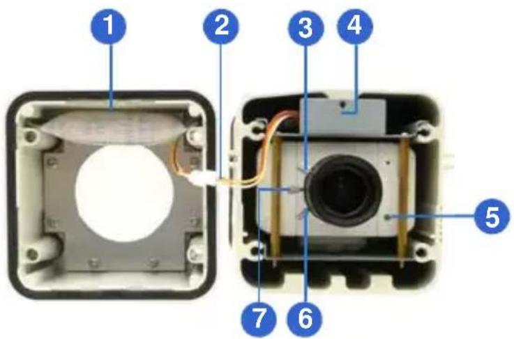
text_image
Exploded view diagram of an electronic device showing internal components numbered 1 to 7Figure 2-1
Note: The Iris Screw (No. 7) is only available in GV-BX520D-E and GV-BX5300-E.
| No. | Name | Description | |
| 1. | Silica gel bag | Desiccant that keeps the camera housing dry. | |
| 2. | IR | power plug Supplies power to the built-in IR LEDs. | |
| 3. | Focus Screw | Adjusts the focus of the camera. | |
| 4. | Module screw | Holds the module in place. | |
| 5. | Status LED | Turns on when the camera is ready for use. | |
| 6. | Zoom Screw | Adjusts the zoom of the camera. | |
| 7. | Iris | Screw Adjusts the iris of the camera. |
2.3.2 GV-BX2510-E / 5310-E
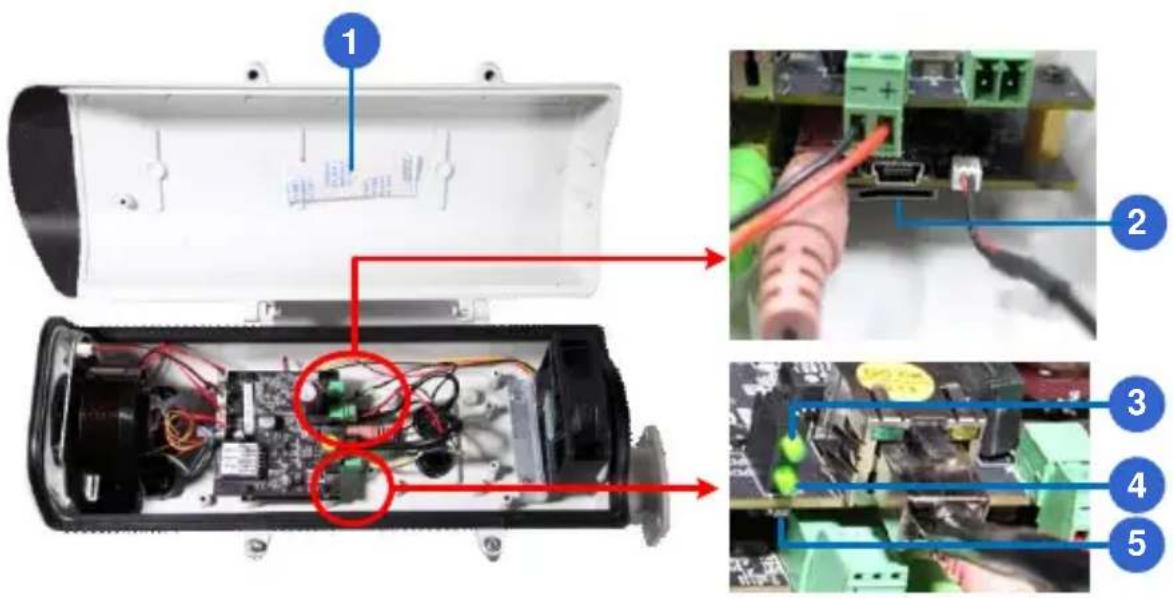
text_image
Labeled diagram of an electronic device showing internal components and wiring, with numbered annotations pointing to specific parts.Figure 2-2
| No. | Name | Description |
| 1. | Silica gel bag | Desiccant that keeps the camera housing dry. |
| 2. | Memory Card Slot | Inserts a micro SD card (SD/SDHC, version 2.0, Class 10) to store recording data. |
| 3. | Power LED | Turns on when the camera is supplied with power. |
| 4. | Status LED | Turns on when the camera is ready for use. |
| 5. | Default | Resets all configurations to factory default. For details, see 2.7 Loading Factory Default. |
2.4 Installation
The IR Arctic Box Camera is designed for outdoor use. Follow the steps below to install your camera.
- Mark the installation site and drill four holes for screw anchors.
- Insert the supplied screw anchors.
- Secure the camera to the wall using the supplied washers and screws.
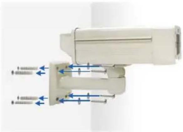
natural_image
Diagram of a white electronic device with blue directional arrows indicating flow or movement (no text or symbols present)Figure 2-3
- Connect the camera with wires and cables. See 2.5 Connecting the Camera.
- Access the live view. See 2.1 Accessing the Live View, GV-IPCam H.264 Firmware Manual.
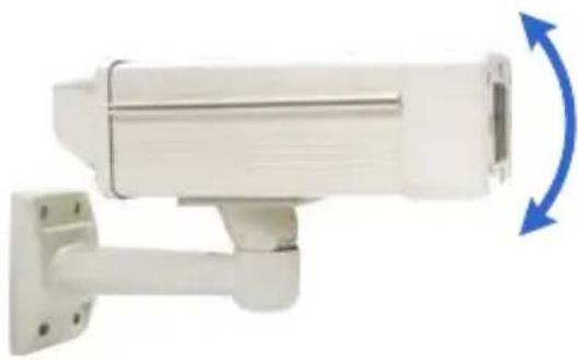
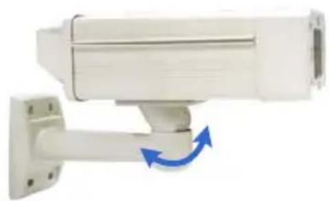
- Based on the live view, adjust the angle of the camera. Loosen the indicated screw with the supplied big torx wrench and adjust the joint.
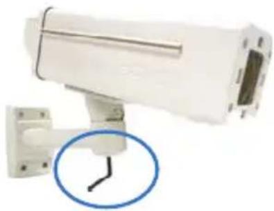
natural_image
White surveillance camera mounted on a wall, with a blue circular annotation highlighting the cable (no text or symbols visible)Figure 2-4
Tilt Adjustment
natural_image
White surveillance camera mounted on a wall-mounted base, with blue directional arrows indicating rotation (no text or symbols visible)Figure 2-5
Pan Adjustment
natural_image
White surveillance camera mounted on a wall-mounted base with blue directional arrows indicating rotation (no text or symbols visible)Figure 2-6
- For GV-BX120D-E / 220D-E / 320D-E / 520D-E / 1500-E / 2400-E / 3400-E / 5300-E, adjust for image clarity based on the live view.
A. Unscrew the cover with the supplied 4 mm torx wrench.
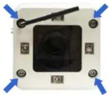
natural_image
Close-up of a mechanical device with a central square component and surrounding buttons (no visible text or symbols)Figure 2-7
B. Hold and unplug the connector.
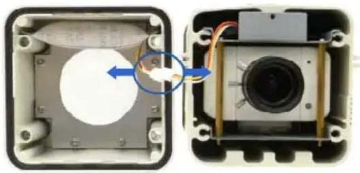
natural_image
Two views of an electronic device showing internal components with wiring and a magnified inset (no text or symbols visible)Figure 2-8
IMPORTANT: Unscrew and remove the cover carefully. Pulling the cover off may cause damages to the inner wiring of the camera.
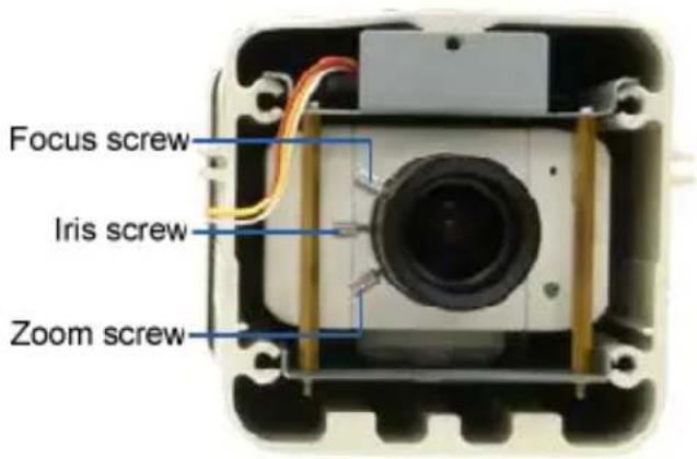
C. Adjust the focus, zoom and iris screws. For a more precise focus, use GV-IP Device Utility. For details, see 2.2 Adjusting Image Clarity, GV-IPCam H.264 Firmware Manual.
text_image
Focus screw Iris screw Zoom screwFigure 2-9
Note: Only GV-BX520D-E and GV-BX5300-E contain an iris screw.
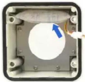
D. Replace the silica gel bag. Paste the sticker to the silica gel bag. Press the sticker several times onto the camera cover to make sure it adheres properly.
natural_image
Interior view of a mechanical or electrical enclosure with a circular component and a blue arrow pointing to it (no visible text or symbols)Figure 2-10
E. Follow steps 7B and 7A to plug the connector back and close the camera cover.
- For GV-BX2510-E / 5310-E, optionally insert a memory card.
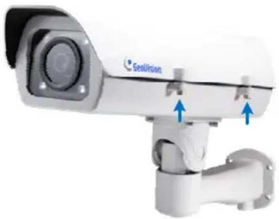
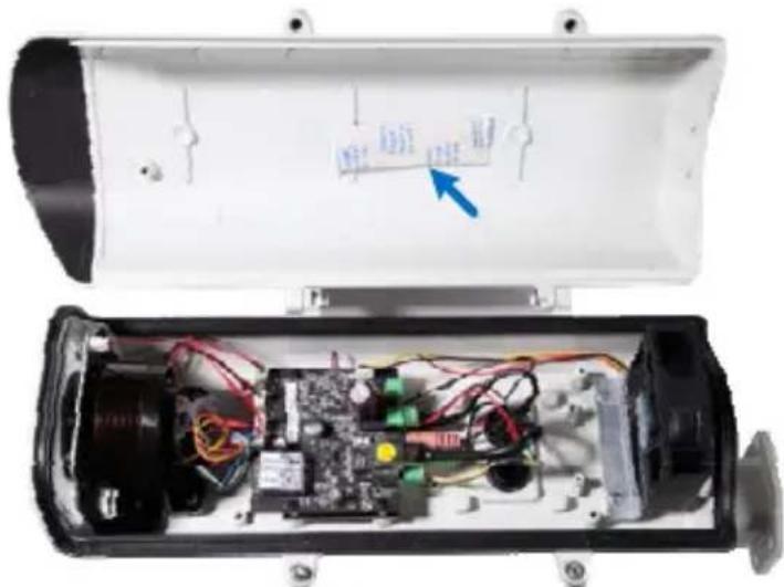
A. Open the camera cover using the supplied torx wrench.
natural_image
Close-up of a security camera with blue arrows pointing to the camera body (no text or symbols visible)Figure 2-11
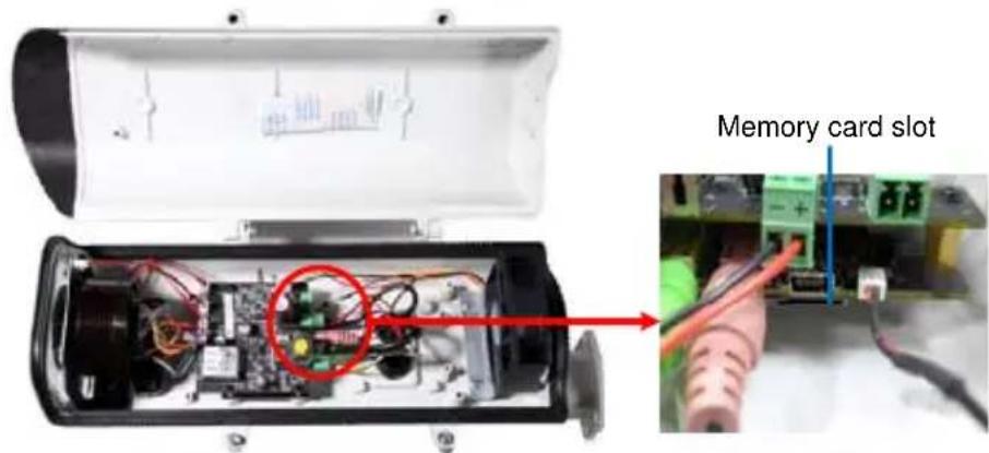
B. Insert a memory card to the card slot.
text_image
Memory card slotFigure 2-12
C. Replace the silica gel bag. Paste the sticker to the silica gel bag. Press the silica gel bag several times onto the camera cover to make sure it adheres properly.
text_image
Internal view of an electronic device showing exposed circuit board, wires, and a labeled component with Chinese text.Figure 2-13
D. Follow step 8A to close the camera cover.
IMPORTANT: The gel bag loses its effectiveness when the dry camera is opened. To prevent the lens from fogging up, replace the silica gel bag every time you open the camera, and conceal the silica gel bag in the camera within 2 minutes of exposing to open air.
2.5 Connecting the Camera
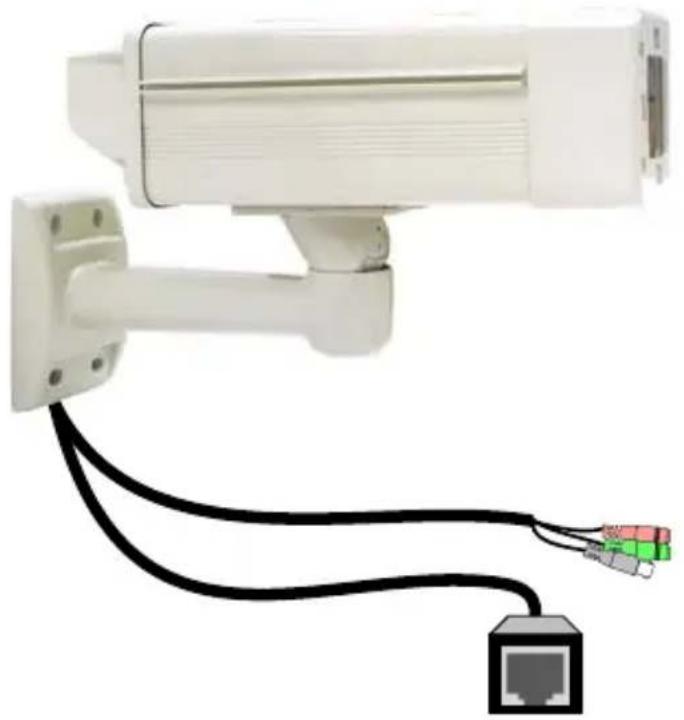
2.5.1 GV-BX120D-E / 220D-E / 320D-E / 520D-E / 1500-E / 2400-E / 3400-E / 5300-E
natural_image
White surveillance camera mounted on a wall with black and red cables, connected to an Ethernet port (no text or symbols visible)Figure 2-14
| No. | Wire Definition | |
| 1 | RJ-45 PoE | |
| 2 | Black BNC | TV out |
| 3 Green RCA Audio Out | ||
| 4 | Pink RCA | Audio In |
-
Optionally connect a speaker (green) and an external microphone (pink).
-
Optionally connect a monitor using a Video Out wire. Enable this function by selecting your signal format at the TV Out field on the Web interface. See 4.1.1 Video Settings, GV-IPCam H.264 Firmware Manual.
-
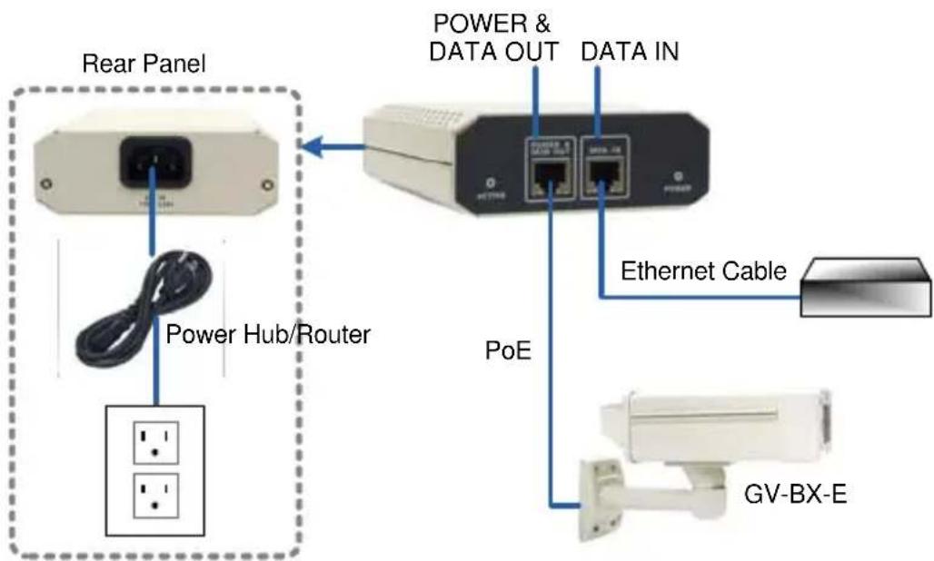
Connect the camera to a GV-PA481 PoE Adapter as illustrated to supply power and network access.
text_image
Rear Panel Power Hub/Router POWER & DATA OUT DATA IN PoE Ethernet Cable GV-BX-EFigure 2-15
-
The status LED of the camera will be on.
-
You are ready to access the live view.
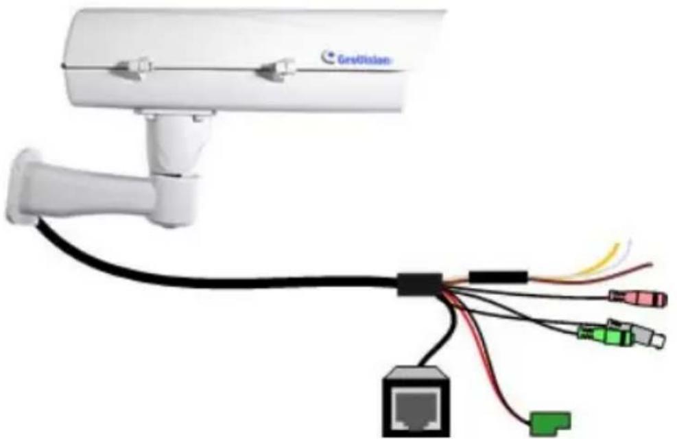
2.5.2 GV-BX2510-E / 5310-E
natural_image
Wireless sensor device with network connections, showing a security camera and Ethernet port (no text or symbols)Figure 2-16
| No. | Wire Definition | |
| 1. | Green RCA Audio Out | |
| 2. | Pink RCA Audio In | |
| 3. | Brown wire Digital Output | |
| 4. | Yellow wire Digital Input | |
| 5. | White wire GND | |
| 6. | Terminal Block DC 48V | |
| 7. | BNC TV Out | |
| 8. | RJ-45 Ethernet/PoE |
- Optionally connect the audio out (green), audio in (pink), digital output (brown), digital input (yellow), and GND.
-
Optionally connect a monitor using a Video Out wire. Enable this function by selecting your signal format at the TV Out field on the Web interface. See 4.1.1 Video Settings, GV-IPCam H.264 Firmware Manual.
-
Supply the camera with power and network access using one of the following methods:
- Use a GV-PA482 Power over Ethernet adapter to connect the camera to power and network as illustrated below. GV-PA482 PoE adapter is an optional accessory. For detail, see Options in the manual.
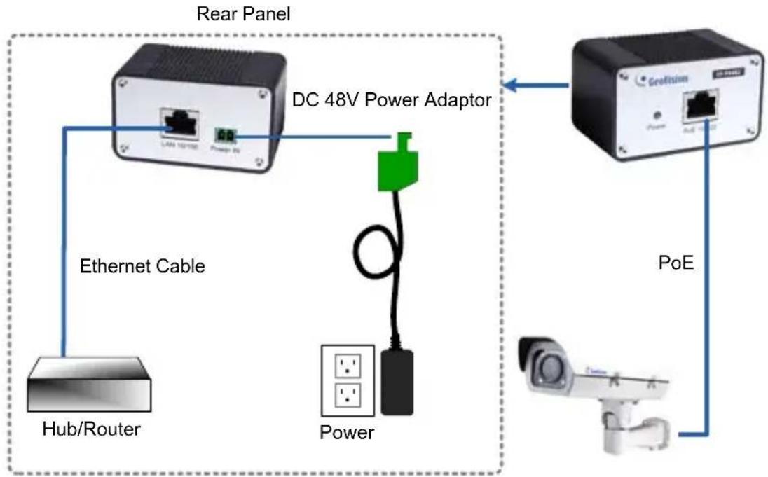
flowchart
graph TD
    A["Remain Panel"] --> B["DC 48V Power Adaptor"]
    B --> C["PoE Sensor"]
    C --> D["Power"]
    D --> E["Hub/Router"]
    E --> F["Ethernet Cable"]
    F --> A
Figure 2-17
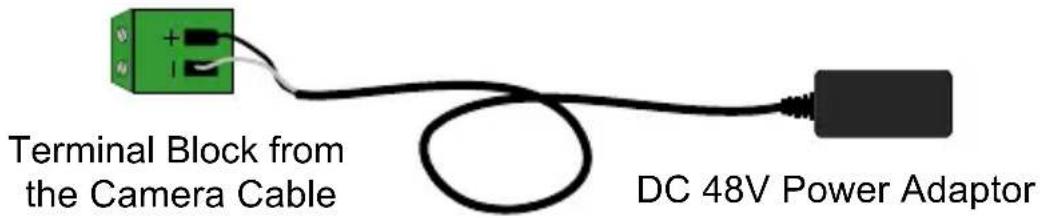
- Use the supplied power adapter. Connect the black wire of the power adaptor to the plus (+) port and the white wire to the negative (-) port. Connect the camera to network with a network cable.
text_image
Terminal Block from the Camera Cable DC 48V Power AdaptorFigure 2-18
GeoVision
- You are ready to access the live view.
2.6 Notice for Using the IR Arctic Box Camera
For GV-BX120D-E / 220D-E / 320D-E / 520D-E / 1500-E / 2400-E / 3400-E
/ 5300-E, make sure that you:
- enable IR LED function on the Web interface after loading the default settings.
- disable the status LED to reduce reflection when a green light spot appears on the live view.
2.6.1 Enabling IR LED after Loading Default
Each GV-IR Arctic Box Camera is equipped with 4 IR LEDs to provide infrared illumination at night. The factory-loaded setting for the IR LED function is enabled. If you have restored the camera to default settings, please follow the steps below to enable the IR LED function.
- In the left menu of Web interface, select Video Settings and then Streaming 1.
- Enable Trigger IR by D/N in IR Check Function.
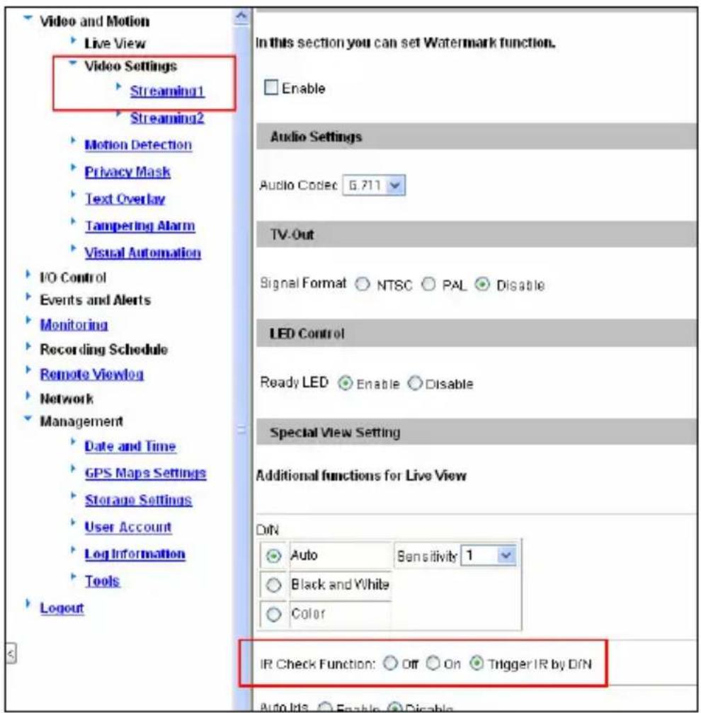
text_image
Video and Motion Live View Video Settings Streaming1 Streaming2 Motion Detection Privacy Mask Text Overlay Tampering Alarm Visual Automation IO Control Events and Alerts Monitoring Recording Schedule Remote Viewlog Network Management Date and Time GPS Maps Settings Storage Settings User Account Log Information Tools Logout In this section you can set Watermark function. Enable Audio Settings Audio Codec 6.711 TV-Out Signal Format NTSC PAL Disable LED Control Ready LED Enable Disable Special View Setting Additional functions for Live View DIN Auto Sensitivity 1 Black and White Color IR Check Function: Off On Trigger IR by DIN Auto RTS Enable DisableFigure 2-17
- Click Apply.
2.6.2 Disabling Status LED under Low Light Conditions
If you have a green light spot on the live view, this is likely due to insufficient light at the installation site, which causes the status LED to reflect on the camera cover. In this case, it is advisable that you disable the status LED.
- In the left menu of Web interface, select Video Settings and then Streaming 1.
- Select Disable in LED Control.
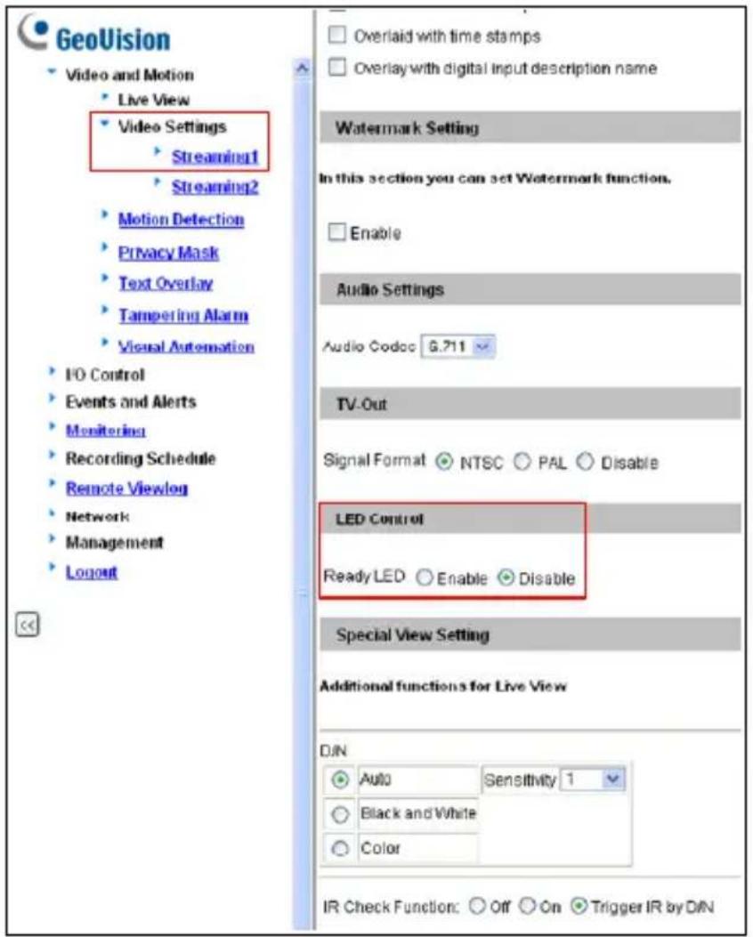
text_image
GeoVision Video and Motion Live View Video Settings Streaming1 Streaming2 Motion Detection Privacy Mask Text Overlay Tampering Alarm Visual Automation I/O Control Events and Alerts Monitoring Recording Schedule Remote Viewlog Network Management Logout Overlaid with time stamps Overlay with digital input description name Watermark Setting In this section you can set Watermark function. Enable Audio Settings Audio Codoc 6.711 TV-Out Signal Format NTSC PAL Disable LED Control Ready LED Enable Disable Special View Setting Additional functions for Live View DIN Auto Sensitivity 1 Black and White Color IR Check Function: Off On Trigger IR by DINFigure 2-18
- Click Apply.
2.7 Loading Factory Default
Note that only GV-BX2510-E and GV-BX5310-E are equipped with a default button.
- Keep the power and network cables (or PoE) connected to the camera.
- Press and hold the default button.
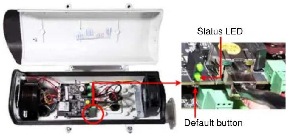
text_image
Status LED Default buttonFigure 2-19
-
Release the default button when the status LED blinks. This shall take about 8 seconds.
-
When the status LED fades, the process of loading default settings is completed and the camera reboots automatically.
Chapter 3 Ultra Box Camera
The Ultra Box Camera is a series of light-weighted cameras designed for indoor usage. Equipped with IR-cut filter and built-in IR LEDs, the Ultra Box Camera provides excellent image quality. The camera supports PoE and can be installed intuitively. Nine models of varying resolutions and focal lengths are available.
| Model No. | Specifications | Description | |
| GV-UBX1301-0FGV-UBX1301-1FGV-UBX1301-2F | Fixed Lens | Fixed Iris, f: 2.8 mm,F/2.0, 1/3” M12Mount | 1.3 MP, H.264,D/N |
| GV-UBX2301-0FGV-UBX2301-1FGV-UBX2301-2F | Fixed Iris, f: 4 / 8mm, F/1.6, 1/3”M12 Mount | 2 MP, H.264,D/N | |
| GV-UBX3301-0FGV-UBX3301-1FGV-UBX3301-2F | 3 MP, H.264,D/N | ||
3.1 Packing List
- Ultra Box Camera
- Supporting rack
- Screw x 3
- Screw anchor x 3
- Power Adapter
• GV-IPCAM H.264 Software DVD
• GV-NVR Software DVD - Warranty Card
Note: The power adapter can be excluded upon request.
3.2 Features
• 1/2.5" progressive scan CMOS
• Dual streams from H.264 or MJPEG
- Frame rate
| Camera Model Frame | Rate |
| GV-UBX1301 Series Up to 30 fps at 1280 x 1024 | |
| GV-UBX2301 Series Up to 30 fps at 1920 x 1080 | |
| GV-UBX3301 Series Up to 20 fps at 2048 x 1536 | |
- Intelligent IR
• Day and night function (with removable IR-cut filter) - Wide Dynamic Range (WDR)
- Defog
• Built-in micro SD card slot (SD/SDHC) for local storage - NAS recording
- Recording assigned by GV-Edge Recording Manager (Windows & Mac)
- Two-way audio
• 2D noise reduction - Motion detection
- Tampering alarm
- Text overlay
- Privacy mask
- IP address filtering
• DC 5V / PoE (IEEE 802.3af) - Megapixel lens
• Support for iPhone, iPad, Android and 3GPP
• 31 languages on Web interface
• ONVIF (Profile S) conformant
3.3 Overview
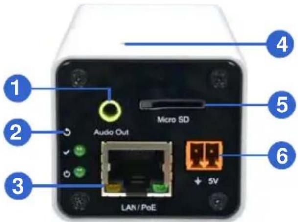
text_image
1 2 3 Audio Out Micro SD 4 5 6 LAN / PoEFigure 3-1
| No. | Name Description | |
| 1 | Audio Out Connects a speaker for audio output. | |
| 2 | Default | Resets the camera to factory default.For details, see 3.6 Loading Factory Default. |
| 3 | LAN / PoE Connects to a 10/100 Ethernet or PoE. | |
| 4 | Microphone Records sounds. | |
| 5 | Memory Card Slot | Inserts a micro SD card (SD/SDHC, version 2.0 only, Class 10) to store recording data. |
| 6 | DC 5V Terminal Block Connects to power. | |
| LED Indicator Description | |
| Status LED | The status LED turns on (green) when the system is ready for use. |
| Power LED | The power LED turns on (green) when power is supplied to the camera. |
3.4 Installation
You can stand the Ultra Box Camera on a plain surface or install it to wall and ceiling. Follow the steps below to install, connect and adjust your Ultra Box Camera.
- To install the device on the wall/ceiling, put the supporting rack on the desired location and make marks for screw anchors.
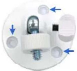
natural_image
Close-up of a white electronic component with blue directional arrows indicating movement or force (no text or symbols)Figure 3-2
- Drill the marks and insert the screw anchors.
- Secure the supporting rack onto the wall/ceiling using the supplied screws.
- Secure the camera onto the supporting rack and fasten the indicated screw.
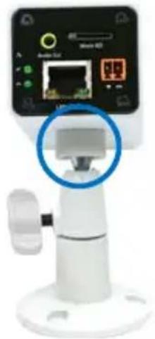
natural_image
Close-up of a white robotic device with a digital display showing network ports and a blue circle highlighting a component (no readable text or symbols)Figure 3-3
-
Connect the network and power cables to the camera. See 3.5 Connecting the Camera.
-
Access the live view. See 2.1 Accessing the Live View, GV-IPCam H.264 Firmware Manual.
-
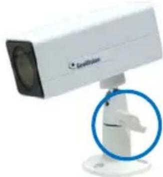
Adjust the angle of the camera based on live view and fasten the indicated screw.
natural_image
White surveillance camera mounted on a stand with a blue circular overlay (no visible text or symbols)Figure 3-4
3.5 Connecting the Camera
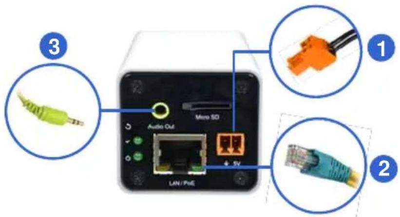
text_image
3 Audio Out Micro SD LAN/PsiE 1 2Figure 3-5
-
Connect power using one of the following methods:
-
Plug the power adapter to the 5V terminal block. The power adapter is an optional device. For detail, see Options in the manual.
- Use the Power over Ethernet (PoE) function and the power will be provided over the network cable.
The power and status LEDs shall turn on (green).
- Use a standard network cable to connect the camera to your network.
- Optionally connect a speaker.
- Insert a micro SD card (SD/SDHC, version 2.0 only, Class 10).
- You are ready to access the live view, adjust the image clarity and configure the basics. See Getting Started, Chapter 2, GV-IPCam H.264 Firmware Manual.
3.6 Loading Factory Default
- Keep the power and network cables connected to the camera.
- Use a pin to press and hold the default button on the back panel of the camera.
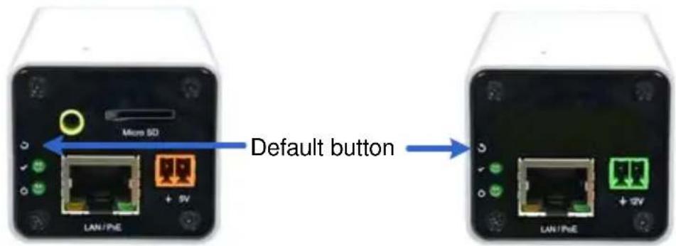
text_image
Micro SD LAN/PHE + 5V Default button LAN/PHE + 2VFigure 3-6
- Release the default button when the status LED blinks. This shall take about 8 seconds.
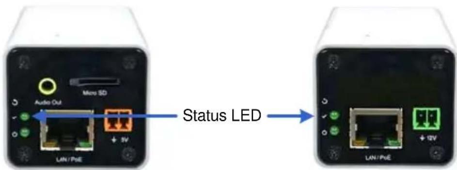
text_image
Audio Out Micro SD + 3V LAN/PnE Status LED LAN/PnEFigure 3-7
- When the status LED fades, the process of loading default settings is completed and the camera reboots automatically. When the status LED turns on (green), the camera is ready for use.
Chapter 4 Target Box Camera
The Target Box Camera (GV-EBX) is a series of light-weighted cameras designed for indoor usage. Equipped with IR-cut filter and built-in IR LEDs, the camera is an entry-level surveillance solution with all the essential features and excellent image quality. The camera supports PoE and can be installed intuitively.
| Model No. | Specifications | Description | |
| GV-EBX1100-0F | Fixed Lens | Fixed Iris, f: 2.8 mm, F/2.0, 1/2.7” M12 Mount | 1.3 MP, H.264, Low Lux, D/N |
| GV-EBX1100-2F | Fixed Iris, f: 3.8 mm, F/1.8, 1/2.7” M12 Mount | ||
4.1 Packing List
- Target Box Camera
• Supporting Rack - Screw x 3
- Screw Anchor x 3
• GV-IPCAM H.264 Software DVD
• GV-NVR Software DVD - Warranty Card
Note: Power adapter can be purchased upon request.
4.2 Features
- 1/3" progressive scan low lux CMOS for GV-EBX1100 Series
- Dual streams from H.264 or MJPEG
Up to 30 fps at 1280 x 1024 for GV-EBX1100 Series - Intelligent IR
• Day and night function (with removable IR-cut filter)
• Built-in microphone - Wide Dynamic Range (WDR)
- Defog
- Motion detection
- Tampering alarm
- Text overlay
- Privacy mask
- IP address filtering
• DC 12V / PoE (IEEE 802.3af) - Megapixel lens
- NAS Recording
- Recording assigned by GV-Edge Recording Manager (Windows & Mac)
• Support for iPhone, iPad, Android and 3GPP
• 31 languages on Web interface
• ONVIF (Profile S) conformant
Note: For optimal performance and compatibility, it is highly recommended to use a GV-NAS System.
4.3 Overview
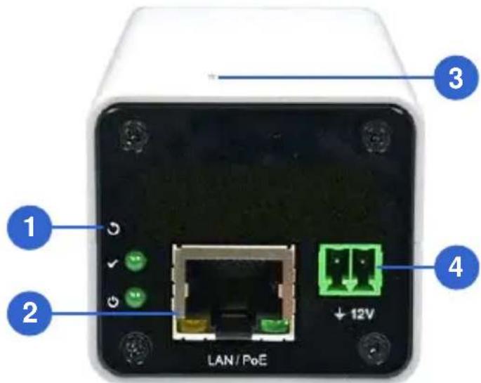
text_image
LAN / PoE 1 2 3 4Figure 4-1
| No. | Name Descri on pti | |
| 1 | Default | Results that or default. For details, see 4.6 Loading Factory Default. |
| 2 LAN / PoE Connects to a 10/100 Ethernet or PoE. | ||
| 3 | Microphone | Records sounds. |
| 4 | DC 12V Terminal Block | r. Connects to powe |
| LED Indicator Description | |
| Status LED | urns on (green) when the The status LED system is ready for use. |
| Power LED | (green) when The power LED tu power is supplied to the camera. |
4.4 Installation
You can stand the Target Box Camera on a plain surface or install it to wall and ceiling. Follow the steps below to install, connect and adjust your Target Box Camera.
- To install the device on the wall/ceiling, put the supporting rack on the desired location and make marks for screw anchors.
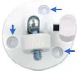
natural_image
Close-up of a white electronic component with blue directional arrows indicating movement or force (no text or symbols)Figure 4-2
- Drill the marks and insert the screw anchors.
- Secure the supporting rack onto the wall/ceiling using the supplied screws.
- Secure the camera onto the supporting rack and fasten the indicated screw.
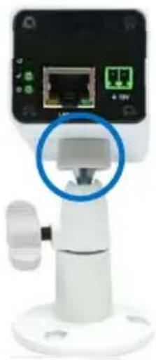
natural_image
Close-up of a white electronic device with a network interface and a blue circular annotation highlighting a component (no readable text or symbols)Figure 4-3
-
Connect the network and power cables to the camera. See 4.5 Connecting the Camera.
-
Access the live view. See 2.1 Accessing the Live View, GV-IPCam H.264 Firmware Manual.
-
Adjust the angle of the camera based on live view and fasten the indicated screw.
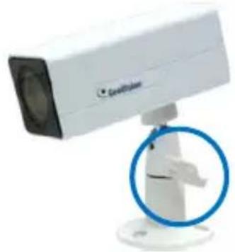
natural_image
White surveillance camera with a blue circular overlay highlighting a mechanical component (no text or symbols visible)Figure 4-4
4.5 Connecting the Camera
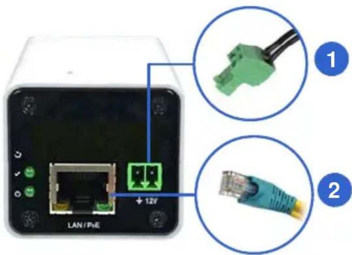
text_image
LAN/PNE + 12V ① ②Figure 4-5
-
Connect power using one of the following methods:
-
Plug the power adapter to the 12V terminal block. The power adapter is an optional device. For detail, see Options in the manual.
- Use the Power over Ethernet (PoE) function and the power will be provided over the network cable.
The power and status LEDs shall turn on (green).
- Use a standard network cable to connect the camera to your network.
- You are ready to access the live view, adjust the image clarity and configure the basics. See Getting Started, Chapter 2, GV-IPCam H.264 Firmware Manual.
4.6 Loading Factory Default
- Keep the power and network cables connected to the camera.
- Use a pin to press and hold the default button on the back panel of the camera.
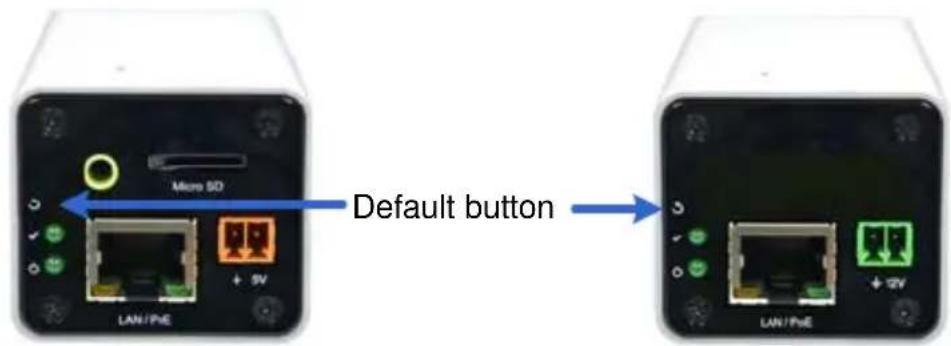
text_image
Micro SD LAN/PHE + 5V Default button LAN/PHE + 2VFigure 4-6
- Release the default button when the status LED blinks. This shall take about 8 seconds.
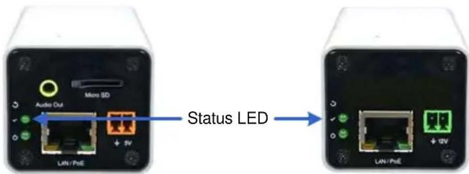
text_image
Audio Out Micro SD + 3V LAN/PnE Status LED LAN/PnEFigure 4-7
- When the status LED fades, the process of loading default settings is completed and the camera reboots automatically. When the status LED turns on (green), the camera is ready for use.
Appendix
A. Supported Lenses for Box Camera
| Provider Model No. | |
| Fujian Forecam Optics | RV0409D.IR |
| RV0515D.IR | |
| RV0820D.IR | |
| EVETAR | EVD03618F-IR |
| EVD04218F-IR | |
| EVD06018F-IR | |
| EVD08018F-IR | |
| EVD12018F-IR | |
| EVD16018F-IR | |
| Pentax | TS3VP213ED-M |