GV-BX1500-3V - Security Camera Geovision - Free user manual and instructions
Find the device manual for free GV-BX1500-3V Geovision in PDF.


User questions about GV-BX1500-3V Geovision
0 question about this device. Answer the ones you know or ask your own.
Ask a new question about this device
Download the instructions for your Security Camera in PDF format for free! Find your manual GV-BX1500-3V - Geovision and take your electronic device back in hand. On this page are published all the documents necessary for the use of your device. GV-BX1500-3V by Geovision.
USER MANUAL GV-BX1500-3V Geovision
natural_image
Collection of security cameras and surveillance cameras displayed against a blue background (no text or symbols visible)
GeoVision
© 2016 GeoVision, Inc. All rights reserved.
Under the copyright laws, this manual may not be copied, in whole or in part, without the written consent of GeoVision.
Every effort has been made to ensure that the information in this manual is accurate. GeoVision, Inc. makes no expressed or implied warranty of any kind and assumes no responsibility for errors or omissions. No liability is assumed for incidental or consequential damages arising from the use of the information or products contained herein. Features and specifications are subject to change without notice. Note: no memory card slot or local storage function for Argentina.
GeoVision, Inc.
9F, No. 246, Sec. 1, Neihu Rd.,
Neihu District, Taipei, Taiwan
Trademarks used in this manual: GeoVision, the GeoVision logo and GV series products are trademarks of GeoVision, Inc. Windows is the registered trademarks of Microsoft Corporation.
May 2016
Contents
Preface...... vi
Naming and Definition...... xv
Note for Connecting to GV-System / GV-VMS ...... xvi
Note for Recording ...... xvii
Note for GV-BX2600...... xviii
Note for GV-EVD5100 / EFD5101 ......xix
Chapter 1 Introduction ......1
1.1 System Requirement ....1
Chapter 2 Getting Started ....3
2.1 Accessing the Live View....3
2.1.1 Checking the Dynamic IP Address 4
2.1.2 Configuring the IP Address....6
2.1.3 Configuring the Wireless Connection.... 8
2.2 Adjusting Image Clarity....12
2.2.1 Using Focus Adjustment Cap 16
2.2.2 Locations of Adjustment Screws.... 17
2.3 Configuring the Basics....20
Chapter 3 Accessing the Camera....21
3.1 Accessing Your Surveillance Images....21
3.2 Functions Featured on the Main Page....23
3.2.1 The Live View Window 24
3.2.2 The Control Panel of the Live View Window 30
3.2.3 Snapshot of Live Video 37
3.2.4 Video Recording 37
3.2.5 Picture-in-Picture and Picture-and-Picture View....38
3.2.6 Alarm Notification.... 41
3.2.7 Video and Audio Configuration ....43
3.2.8 Remote Configuration ....45
3.2.9 Camera Name Display 45
3.2.10 Image Enhancement 45
3.2.11 Visual PTZ 46
3.2.12 Digital PTZ....49
3.2.13 I/O Control 51
3.2.14 Visual Automation 52
3.2.15 Network Status.... 53
Chapter 4 Administrator Mode ....54
4.1 Video and Motion....57
4.1.1 Video Settings....58
4.1.3 Privacy Mask....74
4.1.4 Text Overlay 75
4.1.5 Tampering Alarm....77
4.1.6 Visual Automation 80
4.2 Video Analysis 82
4.2.1 Motion Detection 85
4.2.2 Advanced Video Analysis ....89
4.2.3 Unattended Object / Missing Object Detection....99
4.2.4 Tampering Alarm....102
4.3 I/O Settings.....104
4.3.1 Input Settings....105
4.3.2 Output Settings....107
4.3.3 PTZ Settings....108
4.4 Events and Alerts....109
4.4.1 E-mail 110
4.4.2 FTP....112
4.4.3 Center V2....115
4.4.4 Vital Sign Monitor....117
4.4.5 Backup Center....119
4.4.6 Video Gateway / Recording Server....122
4.4.7 ViewLog Server....124
4.4.8 RTSP/ONVIF 125
4.4.9 Speaker....127
4.5 Monitoring....128
4.5.1 Monitoring Settings for GV-EBL2101 131
4.6 Recording Schedule 132
4.6.1 Recording Schedule Settings 132
4.6.2 I/O Monitoring Settings....133
4.7 Remote ViewLog....134
4.8 Network 135
4.8.1 LAN Configuration.... 135
4.8.2 Wireless Client Mode 137
4.8.3 Advanced TCP/IP....139
4.8.4 UMTS Settings....143
4.8.5 IP Filter Settings....146
4.8.6 SNMP Settings....147
4.9 Management....149
4.9.1 Date & Time Settings 149
4.9.2 Storage Settings 152
4.9.3 User Account 160
4.9.4 Log Information....161
4.9.5 Tools....162
4.9.6 Language....165
Chapter 5 Recording and Playback ....166
5.1 Recording....166
5.2 Playback....167
5.2.1 Playback from the Memory Card 167
5.2.2 Playback over Network....173
5.2.3 Access to the Recorded Files through FTP Server....174
5.2.4 Playback of Daylight Saving Time Events....175
Chapter 6 Advanced Applications .....177
6.1 Upgrading System Firmware....177
6.1.1 Using the Web Configuration Interface 179
6.1.2 Using the IP Device Utility 180
6.2 Backing Up and Restoring Settings....183
6.3 Changing Password....185
6.4 Verifying Watermark....188
6.4.1 Accessing AVI Files 188
6.4.2 Running Watermark Proof....189
6.4.3 The Watermark Proof Window....190
6.5 Downloading Videos from the Micro SD Card....192
6.5.1 Installing the GV-SDCardSync Utility 193
6.5.2 The GV-SDCardSync Utility Window 197
Chapter 7 DVR Configurations ....198
7.1 Setting up an IP Camera on GV-System....207
7.1.1 Customizing IP Camera Settings on GV-System .....210
7.2 Setting Up IP Cameras on GV-VMS....212
7.3 Remote Monitoring with Multi View......215
7.3.1 Connecting to the IP Camera 215
7.4 Remote Monitoring with E-Map......217
7.4.1 Creating an E-Map for the IP Camera....217
7.4.2 Connecting to the IP Camera 219
Chapter 8 CMS Configurations....220
8.1 Center V2....220
8.2 Vital Sign Monitor 223
8.3 Dispatch Server....224
Chapter 9 Smart Device Connection....226
Appendix....227
A. Settings for Internet Explorer 8....227
B. Resolution and Frame Rate......228
C. Support Lists......239
D. RTSP Protocol Command....243
E. Supported UMTS Protocol (3G Modem)......244
F. Dual Stream Support List....245
G. The CGI Command....248
G. The CGI Command....248
H. Power Supply Support List......250
I. Supported Firmware for Flash Memory......252
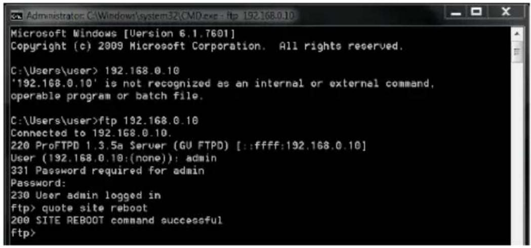
J. How to Remotely Reboot IP Cameras via FTP 253
Preface
Welcome to the GV-IPCAM User's Manual.
The GV-IPCAM has a series of models designed to meet different needs. This Manual is designed for the following models and firmware versions:
Note:
- To upgrade the camera firmware from V2.07 or earlier to the latest version, back up the files in the camera's storage device first before the upgrade and it is required to re-format the memory card after the upgrade.
- The following models are not supported by firmware V3.0 or later:
CB120 / 220
• Models installed with a 32 MB NAND flash
| Model Model Number | Firmware Version | ||
| Box Camera | GV-BX2400-1F ~ 2FGV-BX2400-8F | Fixed Lens | V3.0 |
| GV-BX2600 | Varifocal | V1.0 Lens | |
| GV-BX1500-8FGV-BX2500-8F | Fixed Lens | V3.06 | |
| GV-BX3400-8FGV-BX5300-8F | V3.00 | ||
| GV-BX1500-3VGV-BX2500-3VGV-BX3400-3VGV-BX5300-6V | P-Iris | V3.03 | |
| GV-BX12201 | Varifocal | V1L0 ns | |
| Model Model Number | Firmware Version | ||
| IR Arctic Box Camera | GV-BX2400-EGV-BX5300-E | Varifocal Lens | V3.0 |
| GV-BX1500-E | Motorized Varifocal Lens, P-Iris | V3.06 | |
| GV-BX3400-E | V3.03 | ||
| GV-BX2510-E | Motorized Varifocal Lens | V3.06 | |
| GV-BX5310-E | V3.03 | ||
| Target Box Camera | GV-EBX1100 SeriesGV-EBX2100 Series | Fixed Lens | V1.04 |
| Ultra Box Camera | GV-UBX1301 SeriesGV-UBX2301 SeriesGV-UBX3301 Series | Fixed Lens | V3.0 |
| Mini Fixed Dome | GV-MFD1501 SeriesGV-MFD2501 SeriesGV-MFD2401 SeriesGV-MFD3401 SeriesGV-MFD5301 Series | Fixed Lens | V3.06 |
| V3.00 | |||
| Model Model Number | Firmware Version | ||
| Mini Fixed Rugged Dome | GV-MDR220GV-MDR320GV-MDR520GV-MDR3400 SeriesGV-MDR5300 Series | Fixed Lens | V3.0 |
| GV-MDR1500 Series | V3.06 | ||
| Target Fixed Dome | GV-EFD2101GV-EFD3101GV-EFD5101 | Varifocal Lens, P-Iris | V1.01 |
| Target Mini Fixed Dome | GV-EFD1100 SeriesGV-EFD2100 Series | Fixed Lens | V1.04 |
| Target Mini Fixed Rugged Dome | GV-EDR1100 SeriesGV-EDR2100 Series | Fixed Lens V1.04 | |
| Bullet Camera | GV-BL1500GV-BL2400GV-BL3400 | Varifocal Lens | V3.0 |
| GV-BL2500 | V3.06 | ||
| GV-BL1210GV-BL3410GV-BL5310 | Motorized Varifocal Lens | V3.03 | |
| GV-BL1501GV-BL2501 | Varifocal Lens, P-Iris | V3.06 | |
| GV-BL3401 | V3.01 | ||
| GV-BL1511GV-BL2511 | Motorized Varifocal Lens, P-Iris | V3.06 | |
| GV-BL3411GV-BL5311 | V3.03 | ||
| GV-BL2511-E | Motorized Varifocal Lens, extreme temperature tolerance, P-Iris | V3.06 | |
| GV-BL5311-E | V3.03 | ||
| GV-BL3700(H.265)GV-BL5700(H.265) | Varifocal Lens, P-Iris | V1.00 | |
| Target Bullet Camera | GV-EBL1100-1FGV-EBL1100-2FGV-EBL2100-1FGV-EBL2100-2F | Fixed Lens V1.04 | |
| Target Bullet Camera | GV-EBL2101 | Varifocal Lens | V1.04 |
| Ultra Bullet Camera | GV-UBL1211GV-UBL2411GV-UBL3411 | Motorized Varifocal Lens | V3.03 |
| GV-UBL1511GV-UBL2511 | Coming | ||
| GV-UBL1301 SeriesGV-UBL2401 SeriesGV-UBL3401 Series | Fixed Lens V3.0 | ||
| Vandal Proof IP Dome | GV-VD120D (IK10+, Transparent Cover) GV-VD121D (IK10+, Smoked Cover) GV-VD122D (IK7, Transparent Cover) GV-VD123D (IK7, Smoked Cover) | Varifocal Lens V3.0 | |
| GV-VD220D (IK10+, Transparent Cover) GV-VD221D (IK10+, Smoked Cover) GV-VD222D (IK7, Transparent Cover) GV-VD223D (IK7, Smoked Cover) | |||
| GV-VD320D (IK10+, Transparent Cover) GV-VD321D (IK10+, Smoked Cover) GV-VD322D (IK7, Transparent Cover) GV-VD323D (IK7, Smoked Cover) | |||
| GV-VD1500 GV-VD2400 GV-VD2500 GV-VD3400 | |||
| Vandal Proof IP Dome | GV-VD1530GV-VD2430GV-VD2530GV-VD3430 | Varifocal Lens, high power IR LEDs | V3.0 |
| GV-VD1540GV-VD2440GV-VD2540GV-VD3440GV-VD5340 | Motorized Varifocal Lens, high power IR LEDs | V3.0 | |
| GV-VD3700 (H.265)GV-VD5700 (H.265) | Varifocal Lens, P-Iris | V1.0 | |
| IR Arctic Vandal Proof IP Dome | GV-VD2540-EGV-VD5340-E | Motorized Varifocal Lens, high power IR LEDs, extreme temperatures | V3.0 |
| Target Vandal Proof IP Dome | GV-EVD2100GV-EVD3100GV-EVD5100 | Varifocal Lens, P-Iris | V1.01 |
| PTZ Camera GV | V-PTZ010D | NTSC | V1.09 |
| PAL | |||
| PT Camera | GV-PT130DGV-PT220DGV-PT320D | Fixed Lens | V3.0 |
| Advanced Cube Camera | GV-CA120GV-CA220GV-CAW120GV-CAW220 | Fixed Lens | V3.0 |
| Cube Camera | GV-CB120GV-CB220 | Fixed Lens | V2.14 |
| Fixed IP Dome | GV-FD1500GV-FD2500 | Varifocal Lens | V3.06 |
| GV-FD3400 | V3.03 | ||
| GV-FD3410 | Motorized Varifocal Lens | V3.03 | |
| GV-FD1510GV-FD2510 | V3.06 | ||
| Pinhole Camera | GV-UNP2500 | Fixed | Lens |
V3.
Naming and Definition
| GV-System | GeoVision Analog and Digital Video Recording Software. The GV-System also refers to GV-Multicam System, GV-NVR, GV-DVR and GV-Hybrid DVR at the same time. |
| GV-VMS Geo | Vision Video Management System for IP cameras. |
Note for Connecting to GV-System / GV-VMS
The GV-IPCAM is designed to work with GV-System / GV-VMS, a hybrid or digital video management system. Note the following when the camera is connected to GV-System / GV-VMS:
1 By default, the images are recorded to the memory card inserted in the GV-IPCAM (except GV-IR Arctic Box Camera and Target Series, which are not equipped with a memory card slot).
2 Once the camera is connected to the GV-System / GV-VMS, the resolution set on the GV-System / GV-VMS will override the resolution set on the camera's Web interface. You can only change the resolution settings through the Web interface when the connection to the GV-System / GV-VMS is interrupted.
Note for Recording
1 By default, the images are recorded to the memory card inserted in the GV-IP Camera (except GV-IR Arctic Box Camera and Target Series, which are not equipped with a memory card slot). Make sure the Write recording data into local storage option (see 3.1.1 Video Settings) is enabled. If this option is disabled, the camera will stop recording to the memory card while the live view is accessed through Web browsers or other applications.
2 Mind the following when using a memory card for recording:
- Recorded data on the memory card can be damaged or lost if the data are accessed while the camera is under physical shock, power interruption, memory card detachment or when the memory card reaches the end of its lifespan. No guarantee is provided for such causes.
- The stored data can be lost if the memory card is not accessed for a long period of time. Back up your data periodically if you seldom access the memory card.
- Memory cards are expendable and their durability varies according to the conditions of the installed site and how they are used. Back up your data regularly and replace the memory card annually.
- Replace the memory card when its read/write speed is lower than 6 MB/s or when the memory card is frequently undetected by the camera.
3 It is recommended to use memory cards of the following setting and specifications:
- Apply a battery backup (UPS) to avoid power outage.
- Use Micro SD card of MLC NAND flash, Class 10 for better performance.
Note for GV-BX2600
Frame Rate
Mind the following restrictions, without regard to the resolution of the camera images, when the GV-BX2600 camera is set to 60 fps:
1 The codec MJPEG is not available in the main stream.
2 Dual streaming is not supported.
3 Video analysis functions, including motion detection, are not supported.
4 TV-out is not supported.
5 The frame rate will be dropped to 30 fps during live streaming and recording when the camera starts monitoring.
6 WDR Pro function is not supported.
7 1 or 2 fps will be dropped on the point of obtaining snapshots in JPEG format with the CGI command.
Browser
For the users of Microsoft Internet Explorer, version 11 or later is required to perform the operations through Web browser.
Recording
When GV-BX2600 uses Micro SD card or USB HDD for recording, the camera must not have more than one connection to GeoVision or third-party software.
Note for GV-EVD5100 / EFD5101
When the resolution is set at 2592 x 1944:
1 If the camera is switched to single stream (while stream two is deselected) and Noise Reduction is disabled, the frame rate can reach up to 30 FPS.
2 If the camera is switched to dual streams and Noise Reduction is disabled, the frame rate can reach up to 25 FPS.
3 As long as Noise Reduction is enabled, whether the camera is switched to single stream or dual streams, the frame rate will be 15 FPS.
Chapter 1 Introduction
The GV-IPCAM series offers a comprehensive range of IP cameras for IP surveillance in various environmental conditions.
1.1 System Requirement
To perform the cameras' operations through Web browser, ensure your PC is in good network connection, and use one of the following web browsers:
• Microsoft Internet Explorer 7.x or later
- Google Chrome
- Mozilla Firefox
- Safari
Note:
1 For the users of Internet Explorer 8, additional settings are required. For details, see Appendix A.
2 For GV-BX2600, Internet Explorer 11 or later is required.
3 With non-IE browsers,
A. Motion Detection, Tampering Alarm, Visual Automation, Text Overlay and two-way audio are not supported.
B. only the Play function is available on the live view window (Figure 19-3)
C. RTSP streaming must be kept as enabled. For more detail, see 3.3.8 RTSP.
To access GV-BX12201 images, the PC spec should be met:
| CPU Intel Core i5-4670 | 3.40 GHz |
| Memory DDR3 8 GB RAM | |
| On Board Graphics | Intel HD Graphics 4600 (Versions of driver from year 2014 or later required) |
To access GV-EFD3101 / 5101 and GV-EVD3100 / 5100 images, the PC spec should be met:
| CPU Intel Core i5-4670 | 3.40 GHz |
| Memory DDR3 4 GB RAM | |
| On Board Graphics | Intel HD Graphics 4600 (Versions of driver from year 2014 or later required) |
Chapter 2 Getting Started
This section provides the initial and basic configurations of the GV-IPCAM.
2.1 Accessing the Live View
When the camera is connected to a network with a DHCP server, it will be automatically assigned with a dynamic IP address. See 2.1.1 Checking the Dynamic IP Address to look up this IP address.
However, if you do not have a DHCP server on your network, access the camera by its default IP address 192.168.0.10 and see 2.1.2 Configuring the IP Address for more detail.
Note: By default, GV-PTZ010D is assigned with the fixed IP address 192.168.0.10.
2.1.1 Checking the Dynamic IP Address
Follow the steps below to look up the IP address and access the Web interface.
- Install the GV-IP Device Utility program included on the Software DVD.
Note: The PC installed with GV-IP Device Utility must be under the same LAN with the camera you wish to configure.
- On the GV-IP Utility window, click the button to search for the IP devices connected in the same LAN. Click the Name or Mac Address column to sort.
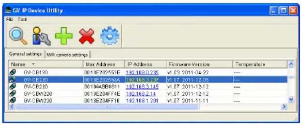
text_image
GV IP Device Utility File Tool General settings | NVR camera settings | Name Mac Address IP Address Firmware Version Temperature GV-CB120 0013E202553E 192.169.0.235 √1.03 2011-04-22 — GV-CB120 0013E202553A 192.168.3.237 √1.07 2011-12-05 — GV-CB120 0019AABB8611 192.168.3.145 √1.07 2011-12-12 — GV-CBW220 0013E204FF4E 192.169.2.14 √1.07 2011-12-12 — GV-CBW220 0013E204FF16 192.168.1.201 √1.07 2011-11-11 —Figure 2-1
- Find the camera with its Mac Address, click on its IP address and select Web Page.
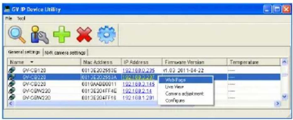
text_image
GV IP Device Utility File Tool General settings | NVR camera settings | Name Mac Address IP Address Firmware Version Temperature GV-CB120 0013E202553E 192.168.0.235 V1.03 2011-04-22 GV-CB220 0013E202553A 192.168.3.237 Web Pages GV-CB220 0019AADD0911 192.168.3.145 Live View GV-CBW220 0013E204FF4E 192.168.2.14 Camera adjustment GV-CBW220 0013E204FF16 192.168.1.201 ConfigureFigure 2-2
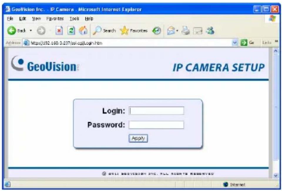
- The login page appears.
text_image
GeoVision Inc. - IP Camera - Microsoft Internet Explorer File Edit View Favorites Tools Help Back Search Favorites Address https://192.168.3.297/ssl.cgi/Login.htm GeoVision IP CAMERA SETUP Login: Password: Apply 2011 GEOVISION INC. ALL RIGHTS RESERVED InternetFigure 2-3
- Type the default ID and password admin and click Apply to log in.
2.1.2 Configuring the IP Address
Follow the steps below to configure the IP address.
- Open your web browser, and type the default IP address http://192.168.0.10.
- In both Login and Password fields, type the default value admin. Click Apply.
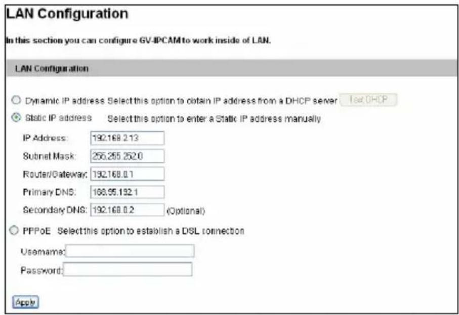
- In the left menu, select Network and then LAN to begin the network settings. This page appears.
text_image
LAN Configuration In this section you can configure GV-IPCAM to work inside of LAN. LAN Configuration Dynamic IP address Select this option to obtain IP address from a DHCP server Test DHCP Static IP address Select this option to enter a Static IP address manually IP Address: 192.168.2.13 Subnet Mask: 255.255.252.0 Router/Gateway: 192.168.0.1 Primary DNS: 168.95.192.1 Secondary DNS: 192.168.0.2 (Optional) PPPoE Select this option to establish a DSL connection Username: Password: ApplyFigure 2-4
- Select Dynamic IP address, Static IP address or PPPoE and type the required network information.
- Click Apply. The camera is now accessible by entering the assigned IP address on the web browser.
IMPORTANT:
-
If Dynamic IP Address or PPPoE is enabled, you need to know which IP address the camera will get from DHCP server or ISP to log in. If your camera is installed in the LAN, use the GV-IP
Device Utility to look up its current dynamic IP address. See 2.1.1 Checking the Dynamic IP Address. If your camera uses a public dynamic IP address via PPPoE, use the dynamic DNS Service to obtain a domain name that is linked to the camera's changing IP address first. For details on Dynamic IP Address and PPPoE, see 4.7.1 LAN Configuration and 4.7.3 Advanced TCP/IP. -
If Dynamic IP Address or PPPoE is enabled and you cannot access the camera, you may have to reset it to the factory default and then perform the network settings again.
To restore your camera to default settings, see Loading Factory Default in the corresponding Hardware Manual.
2.1.3 Configuring the Wireless Connection
You may create wireless connection to the Internet for:
- Box Camera: GV-BX1200 series / 1300 series / 1500 series / 2400 series / 2500 series / 3400 series / 5300 series
- Wireless Advanced Cube Camera: GV-CAW120/220
-
Mini Fixed Dome: GV-MFD1501 series / 2401 series / 2501 series / 3401 series / 5301 series
-
To set up the wireless LAN for the first time, power on and connect a standard network cable to the camera.
-
An IP address will be automatically assigned to the camera. Use GV IP Device Utility to search for the device. For details, see 2.1.1 Checking the Dynamic IP Address.
-
Configure the wireless settings.
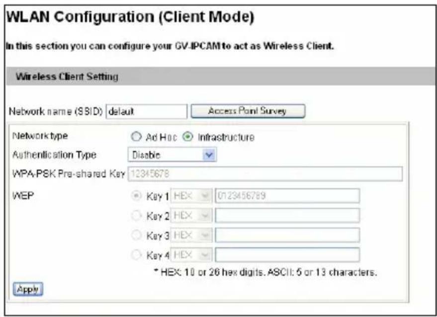
A. On the Web interface, select Network, select Wireless and Client Mode. This dialog box appears.
text_image
WLAN Configuration (Client Mode) In this section you can configure your GV-IPCAM to act as Wireless Client. Wireless Client Setting Network name (SSID) default Access Point Survey Network type Ad Hoc Infrastructure Authentication Type Disable WPA-PSK Pre-shared Key 12345678 WEP Key 1 HEX 0123456789 Key 2 HEX Key 3 HEX Key 4 HEX * HEX: 10 or 26 hex digits. ASCII: 5 or 13 characters. ApplyFigure 2-5
B. Type the Network Name (SSID) or click the Access Point Survey button to search and select for the available Access Points/wireless stations.
C. Select Ad-Hoc or Infrastructure for the Network type.
D. Select the Authentication Type using the drop-down list. You can also obtain this information by clicking the Access Point Survey button.
E. Type the WPA-PSK Pre-shared Key or WEP depending on the encryption setting for the Access Point.
F. Click Apply to save the configuration.
Note:
- Your encryption settings must match those used by the Access Points or wireless stations with which you want to associate.
- When Ad Hoc is used, only WEP encryption is supported.
- When you lose the wireless access, you can still access the unit by connecting it to a LAN and using the GV IP Device Utility to search for the device.
- For detailed information on configuring the wireless LAN, see 4.7.2 Wireless Client Mode.
4. Enable wireless LAN.
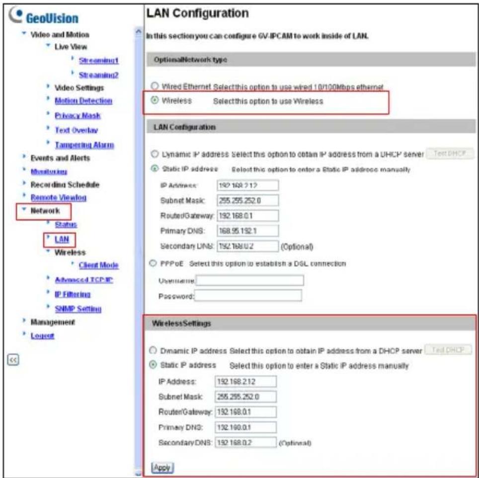
A. On the Web interface, select Network and LAN. This page appears.
text_image
GeoVision Video and Motion Live View Streaming1 Streaming2 Video Settings Motion Detection Privacy Mask Text Overlay Tampering Alarm Events and Alerts Monitoring Recording Schedule Remote Viewlog Network Status LAN Wireless Client Mode Advanced TCP-IP IP Filtering SNMP Setting Management Logout LAN Configuration In this section you can configure GV IPCAM to work inside of LAN. OptionalNetwork type Wired Ethernet Select this option to use wired 10/100Mbps ethernet Wireless Select this option to use Wireless LAN Configuration Dynamic IP address: Select this option to obtain IP address from a DHCP server Static IP address Select this option to enter a Static IP address manually IP Address: 192.168.2.12 Subnet Mask: 255.255.252.0 RoutedGateway: 192.168.0.1 Primary DNS: 168.95.192.1 Secondary DNS: 192.168.0.2 (Optional) PPPoE Select this option to establish a DSL connection Username: Password: WirelessSettings Dynamic IP address Select this option to obtain IP address from a DHCP server Static IP address Select this option to enter a Static IP address manually IP Address: 192.168.2.12 Subnet Mask: 255.255.252.0 RouterGateway: 192.168.0.1 Primary DNS: 192.168.0.1 SecondaryDNS: 192.168.0.2 (Optimal) ApplyFigure 2-6
B. Select Wireless for Optional Network Type.
C. To use a dynamic IP address assigned by the DHCP server, select Dynamic IP address. To use a fixed IP address, select Static IP address and type the IP address information.
- Click Apply. The Camera will start creating a wireless connection to the access point.
Note: For GV-CAW120/220, the LAN LED turns blue when the connection is established.
- Unplug the Ethernet cable.
2.2 Adjusting Image Clarity
Note the procedures described in this section only apply to the cameras that allow manual focus adjustment. To adjust focus of a PTZ camera, refer to Focus Adjustment in corresponding the Hardware Manual; for Cube Camera and Advanced Cube Camera, refer to Camera Adjustment in 3.2.2 The Control Panel on the Live View Window.
After you have connected your camera to the network, follow the steps below to adjust image clarity.
- Make sure you have installed the GV-IP Device Utility program included on the Software DVD.
Note: The PC installed with GV-IP Device Utility must be under the same LAN with the camera you wish to configure.
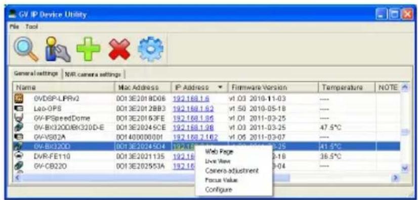
- On the GV-IP Utility window, click the button to search for the IP devices connected in the same LAN. Click the IP Address of the camera you desire. A drop-down list appears.
text_image
GVI IP Device Utility File Tool General settings | NVR camera settings Name Mac Address IP Address Firmware Version Temperature NOTE GVDSP-LPRV2 0013E2018D06 192.168.1.6 vt.03 2010-11-03 ---- Lao-GPS 0013E2012BB3 192.168.1.62 vt.50 2010-05-18 ---- GV-IPSpeedDome 0013E20163FE 192.168.1.86 vt.01 2011-03-25 ---- GV-BX320DBK320D-E 0013E20245CE 192.168.1.98 vt.03 2011-03-25 47.5°C GV-VS02A 001400000001 192.168.2.162 vt.05 2011-03-07 ---- GV-BX320D 0013E20245D4 19PAB Web Page 41.5°C DVR-FE110 0013E2021135 192.16 Live View 36.5°C GV-CB220 0013E202553A 192.16 Camera adjustment 3-04 ---- ConfigureFigure 2-7
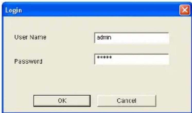
- Select Focus Value. The Login dialog box appears.
text_image
Login User Name admin Password ***** OK CancelFigure 2-8
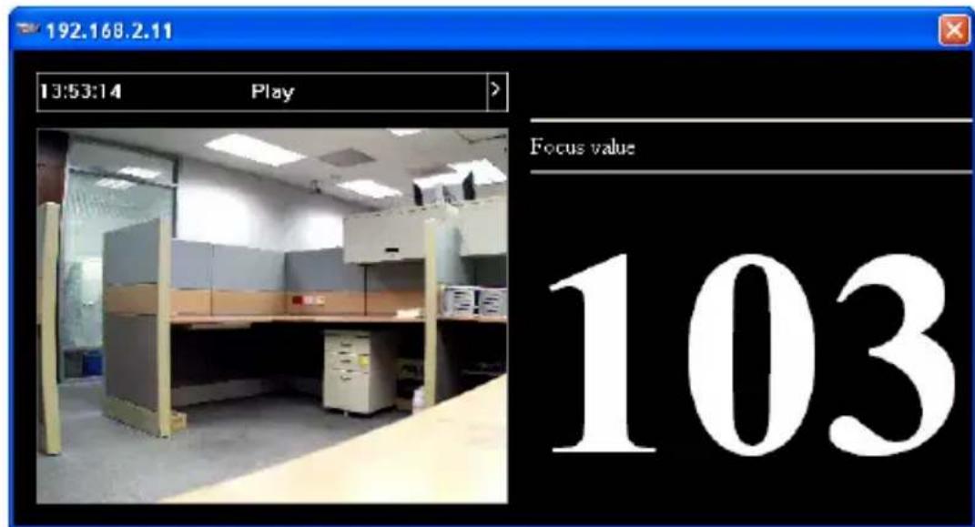
- Type the user name and password of the camera selected. The default is admin for both user name and password. This window appears.
text_image
192.168.2.11 13:53:14 Play Focus value 103Figure 2-9
- For IK10+ models (GV-VD120D / 121D / 220D / 221D / 320D / 321D / 1500 / 2400 / 2500 / 3400 / 1530 / 2430 / 2530 / 3430), hold the supplied Focus Adjustment Cap over the camera view. For details, see 2.2.1 Using Focus Adjustment Cap for details.
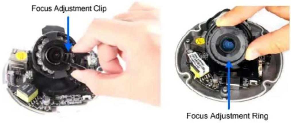
- For Target Mini Fixed Dome and Target Mini Fixed Rugged Dome, hold the camera cover close to the lens and use the supplied focus adjustment tool for precise focus adjustment.
text_image
Focus Adjustment Clip Focus Adjustment RingFigure 2-10
- For Mini Fixed Dome and Mini Fixed Rugged Dome, hold the camera cover close to the lens for precise focus adjustment. For locations of adjustment screws and rings in each model, see 2.2.2 Locations of Adjustment Screws.
- Adjust the Focus Screw and the Zoom Screw of the camera slowly until the focus value reaches the maximum. For example, the maximum focus value in Step 4 is 103. For locations of adjustment screws in each model, see 2.2.2 Locations of Adjustment Screws.
Note:
- Do not over tighten the screws. The screws only need to be as tight as your fingers can get them to be. Do not bother using any tool to get them tighter. Doing so can damage the structure of lens.
- The maximum focus value may vary when the environment changes.
2.2.1 Using Focus Adjustment Cap
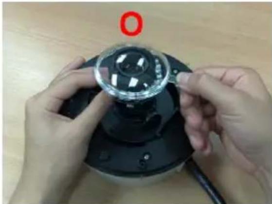
The Focus Adjustment Cap is only supplied for IK10+ models (GV-VD120D / 121D / 220D / 221D / 320D / 321D / 1500 / 2400 / 2500 / 3400 / 1530 / 2430 / 2530 / 3430).
natural_image
Close-up of hands adjusting a small transparent object on a black device (no visible text or symbols)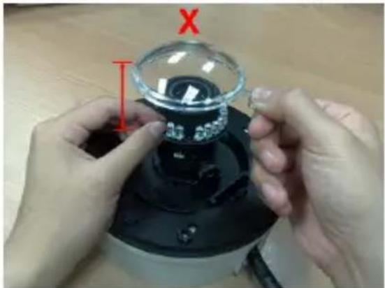
text_image
Photo showing hands holding a small glass bowl with red 'X' and dimension label, likely demonstrating a scientific experiment or measurement setup.Hold the Focus Adjustment Cap on top of the camera view and keep it close to the camera.
Do not leave a distance between the Focus Adjustment Cap and the camera.
2.2.2 Locations of Adjustment Screws
| Models Adjustment Screws | |
| Box Camera | 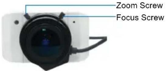 |
| Bullet Camera | -Zoom Screw-Focus Screw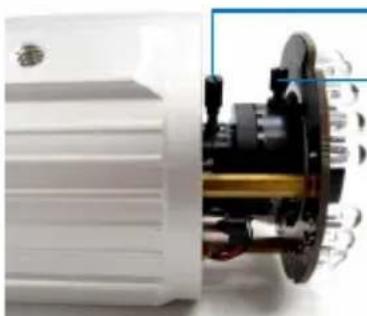 |
| Vandal Proof IP Dome | -AHCW] |
| Fixed IP Dome | -Focus Screw-Zoom Screw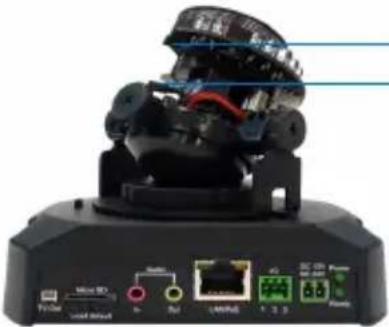 |
| GV-MFD1501 / 2401 /3401 / 5301 | 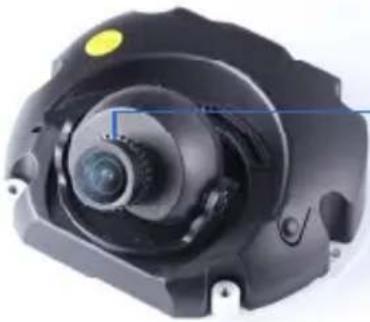 — Focus Ring — Focus Ring |
| GV-MDR220 / 320 | 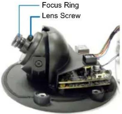 |
| GV-MDR1500 / 3400 /5300 | 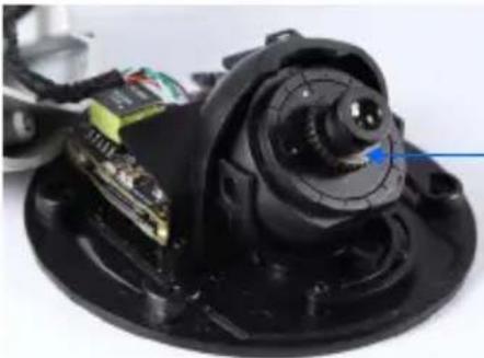 — Focus Ring — Focus Ring |
| GV-VD3700 / 5700 | 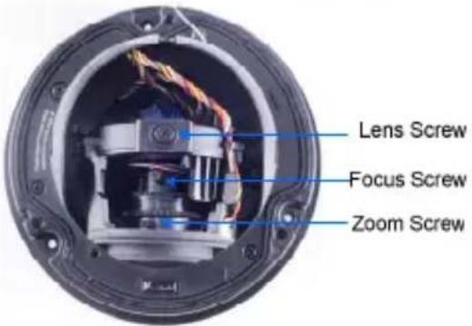 |
Note:
- The adjustment screws of Box Camera may vary for different models.
- To focus GV-MFD and GV-MDR, loosen the lens screw first and slowly adjust the focus ring. Some models may need a T6 screw driver to loosen the camera lens. If you have a problem of obtaining this type of screw driver, please contact our overseas offices for further assistance.
2.3 Configuring the Basics
Once the camera is properly installed, the following important features can be configured using the browser-based configuration page and are discussed in the following sections in this manual:
- Date and time adjustment: see 4.8.1 Date & Time Settings.
- Login and privileged passwords: see 4.8.3 User Account.
• Network gateway: see 4.7 Network. - Camera image adjustment: see 3.2.2 The Control Panel of the Live View Window.
- Video format, resolution and frame rate: see 4.1.1 Video Settings.
Chapter 3 Accessing the Camera
Two types of users are allowed to log on to the GV-IPCAM:
Administrator and Guest. The Administrator has full access to all system configurations, while the Guest can only access the live view (except the Camera Adjustment settings) and network status.
3.1 Accessing Your Surveillance Images
Once installed, your camera is accessible on a network. Follow these steps to access your surveillance images:
- Start your web browser.
- Enter the IP address or the domain name of the camera in the Location/Address field of your browser.
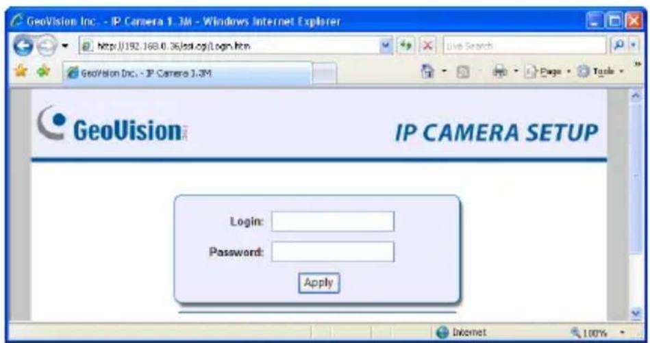
text_image
GeoVision Inc. - IP Camera 1.3M - Windows Internet Explorer http://192.168.0.36/sai.cgi/Login.htm GeoVision Inc. - IP Camera 1.3M GeoVision™ IP CAMERA SETUP Login: Password: Apply Internet 100%Figure 3-1
-
Enter the login name and password.
-
The default login name and password for Administrator are admin.
• The default login name and password for Guest are guest. -
Click Apply. A video image, similar to the example on Figure 3-2, is now displayed in your browser.
Note: To enable the updating of images in Internet Explorer, you must set your browser to allow ActiveX Controls and perform a once-only installation of GeoVision's ActiveX component onto your computer.
3.2 Functions Featured on the Main Page
This section introduces the features of the Live View window and Network Status on the main page. The two features are accessible by both Administrator and Guest.
Main Page of Guest Mode
▼ Video and Motion
Live View
▶ Camera
Network
Status
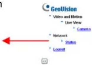
text_image
GeoVision Video and Motion Live View Camera Network Status Legend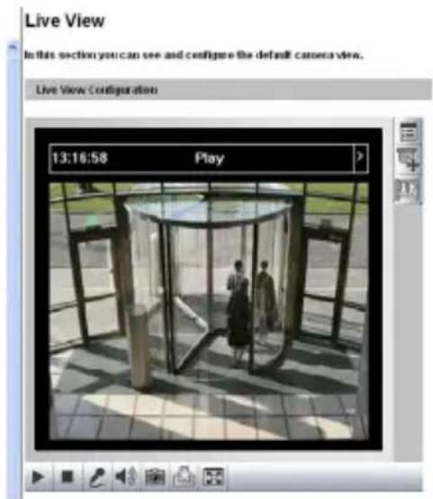
text_image
Live View In this section you can see and configure the default camera view. Live View Configuration 13:16:58 PlayFigure 3-2
The GV-IPCAM can process one video stream in two different codec and image settings. In the Administrator mode, both streams are available. Click Streaming 1 or Streaming 2 in the left menu to access the live view. In the Guest mode, only one stream is available, as shown in Figure 3-2.
3.2.1 The Live View Window
Internet Explorer
When accessing the live view using Internet Explorer, the following window appears.
Live View
In this section you can see and configure the default camera view.
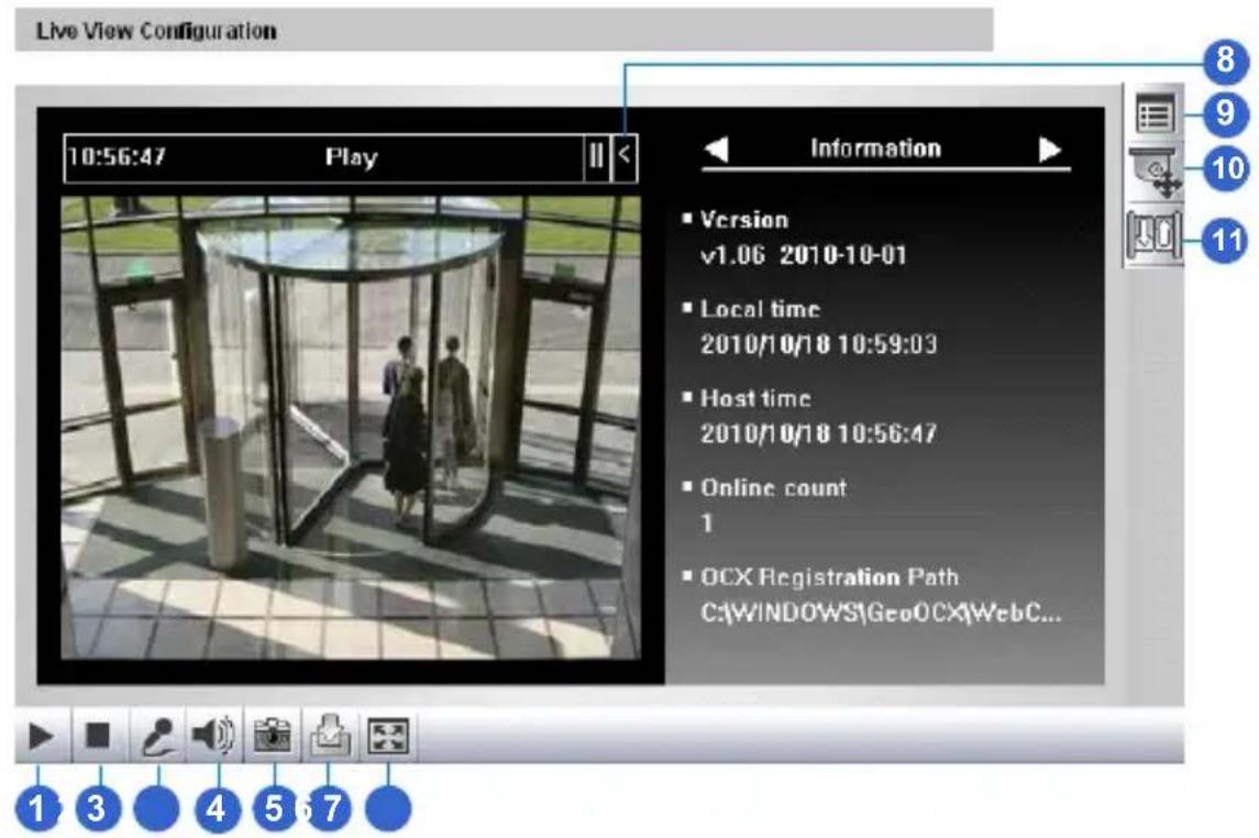
text_image
Live View Configuration 10:56:47 Play Information ■ Version v1.06 2010-10-01 ■ Local time 2010/10/18 10:59:03 ■ Host time 2010/10/18 10:56:47 ■ Online count 1 ■ OCX Registration Path C:\WINDOWS\GeoOCX\WebC... 1 3 4 5 6 7Figure 3-3A
Live View
In this section you can see and configure the default camera view.
Live View Configuration
text_image
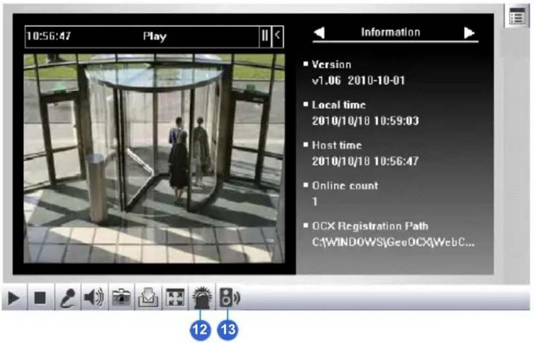
10:56:47 Play Information ■ Version v1.06 2010-10-01 ■ Local time 2010/10/18 10:59:03 ■ Host time 2010/10/18 10:56:47 ■ Online count 1 ■ OCX Registration Path C:\WINDOWS\GeoOCX\WebC... 12 13Figure 3-3B
| No. | Name Function | |
| 1 | Play Plays live video | o. |
| 2 | Stop Stops playing | video. |
| 3 | Microphone | Broadcasts to the surveillance site from a remote PC. Note this function is not available for Ultra Bullet Camera and Target Series. For Cube Camera and Advanced Cube Camera, you can click the Push to talk button (from the pop-up menu) for the camera to switch between audio transmission and reception, where only one party can speak at a time. |
| 4 | Speaker | Transfers sounds of the surveillance site to a remote PC. Note this function is not available for Mini Fixed Rugged Dome, Ultra Bullet Camera, Target Bullet Camera, and Target Mini Fixed Rugged Dome, and Pinhole Camera. |
| 5 | Snapshot | Takes a snapshot of live video. --- See 3.2.3 Snapshot of Live Video. |
| 6 | File Save | Records live video to the local computer. --- See 3.2.4 Video Recording. |
| 7 | Full Screen | Switches to full screen view. Right-click the image to have these options: Snapshot, Full Screen, Resolution, Zoom In, Zoom Out, PIP and PAP. --- See 3.2.5 Picture-in-Picture and Picture-and-Picture View for PIP and PAP views |
| 8 | Control Panel | Displays the camera information, video settings, audio data rate, I/O device status, images captured upon alarm, and GPS location of the camera. Also allows you to adjust image quality and install the program from the hard drive. |
| 9 | Show System Menu | Brings up these functions: Alarm Notify, Video and Audio Configuration, Remote Config, Show Camera Name and Image Enhance. --- See 3.2.6 Alarm Notification, 3.2.7 Video and Audio Configuration, 3.2.8 Remote Configuration, 3.2.9 Camera Name Display, and 3.2.11. Image Enhancement. |
| 10 | PTZ Control Panel | Enables the PTZ Control Panel or the Visual PTZ. Note this function is supported by PTZ Camera and PT Camera, and only partially supported by GV-IP Cameras with motorized varifocal lens. --- See The PTZ Control Panel (Hardware Manual) --- See 3.2.11 Visual PTZ |
| 11 | I/O Control | Enables the I/O Control Panel or the Visual Automation. Note this function is only supported by cameras with I/O function. --- See 3.2.13 I/O Control. |
| 12 | LED Control | Click to turn the Alarm LED on and/or adjust the brightness sensitivity. Note this function is only available for Advanced Cube Camera. |
| 13 | Alarm Speaker | Click to sound the alarm and/or adjust its volume.To sound the alarm upon motion or tampering events, see 4.3.9 Speaker for setup steps.Note this function is only available for Advanced Cube Camera. |
Non-IE Browsers
When accessing the live view using Google Chrome, Firefox or Safari, this window appears. Note the following functions are not supported on non-IE browsers: Motion Detection, Tampering Alarm, Visual Automation, Text Overlay and Two-Way Audio.
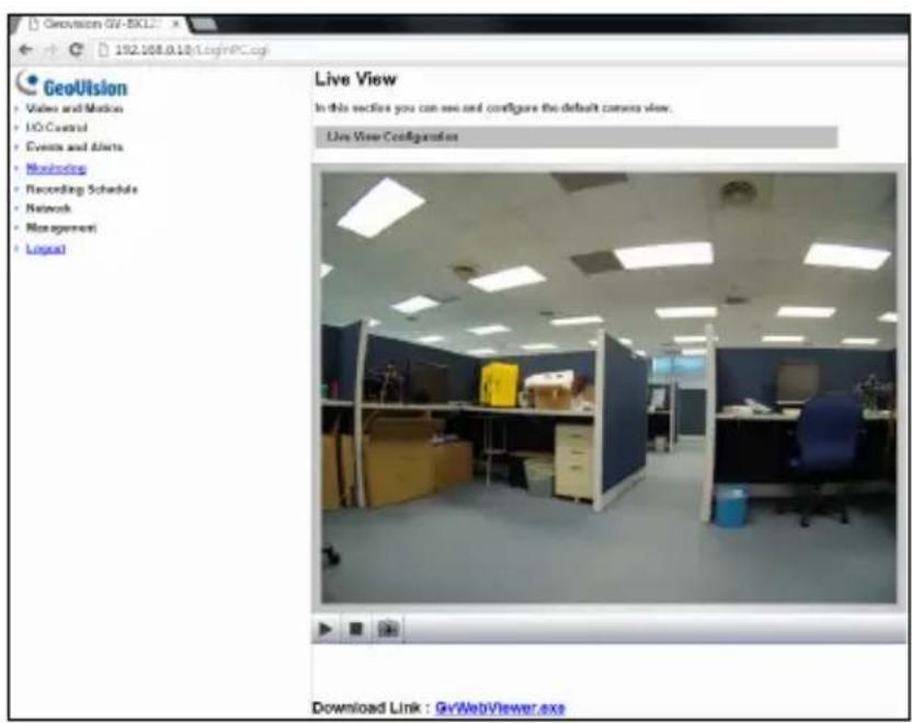
text_image
GeoVision 01-BKL2 182.168.0.10\loginPC.cgi GeoVision Video and Motion I/O Control Events and Alerts Monitoring Recording Schedule Network Management Legal Live View In this section you can see and configure the default camera view. Live View Configuration Download Link : GvWebViewer.axeFigure 3-4
Note: Non-IE browsers do not support OCX plugin, so the smoothness of the live view is obstructed. For users of non-IE browsers, to enjoy smooth live view, download GV-WebViewer right after you log on and you can also have access to the features of Motion Detection, Tampering Alarm, Visual Automation, Text Overlay and Two-Way Audio.
3.2.2 The Control Panel of the Live View Window
To open the control panel of the Live View window, click the arrow button on top of the window. You can access the following functions by using the right and left arrow buttons on the control panel.
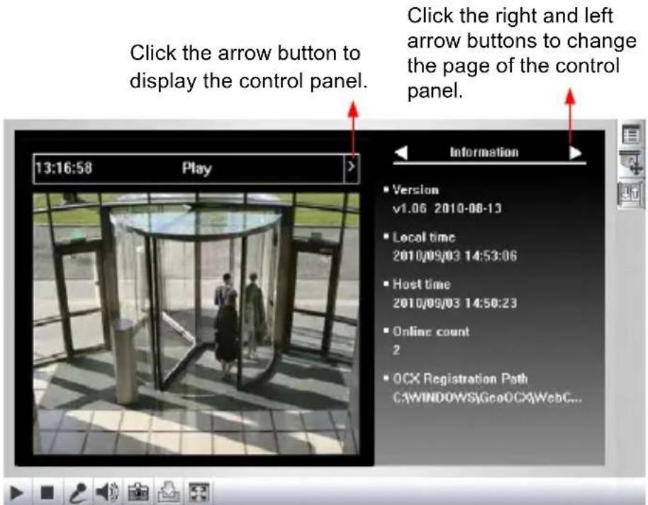
text_image
Click the arrow button to display the control panel. 13:16:58 Play Information ■ Version v1.06 2010-08-13 ■ Local time 2010/09/03 14:53:06 ■ Host time 2010/09/03 14:50:23 ■ Online count 2 ■ OCX Registration Path C:\WINDOWS\GeoOCX\WebC...Figure 3-5
Tip: Administrator may also access live view and camera adjustment settings using the GV-IP Device Utility:
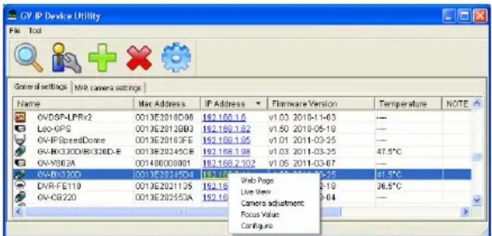
text_image
GV IP Device Utility File Tool General settings | NVR camera settings | Name Mac Address IP Address Filmware Version Temperature NOTE GVDSP-LPRv2 0013E2018D06 192.168.1.6 v1.03 2010-11-03 --- Leo-GPS 0013E2012GB3 192.168.1.62 v1.50 2010-05-19 --- GV-IPSpeedDome 0013E20163FE 192.168.1.95 v1.01 2011-03-25 --- GV-BX320D/BX320D-E 0013E20245CE 192.168.1.98 v1.03 2011-03-25 47.5°C GV-VB02A 001400000001 192.168.2.102 v1.05 2011-03-07 --- GV-BX320D 0013E20245D4 192.16 Web Page 4-25 41.5°C DVR-FE110 0013E2021135 192.16 Live View 2-19 36.5°C GV-CB220 0013E202553A 192.16 Camera adjustment 3-04 ---[Information] Displays the version of the camera, time of the local computer, time of the camera (host time), the number of users logging in the camera and the OCX registration path.
[Video] Displays the current video codec, resolution and data rate.
[Audio] Displays the audio data rates when the microphone and speaker devices are enabled.
[I/O Control] Note this function is only supported by cameras with I/O function. Provides a real-time graphic display of the input and output status. You can force the output to be triggered by double-clicking its icon.
[Alarm Notify] Displays the captured images by sensor triggers and motion detection. For this function to work, you have to configure the Alarm Notification settings first. See 3.2.6 Alarm Notification.
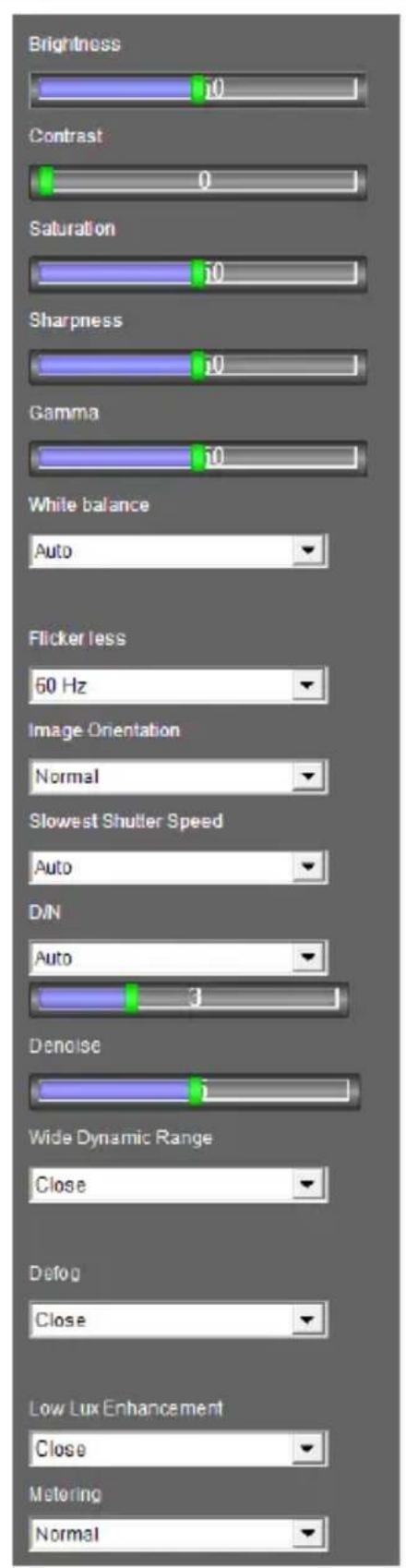
[Camera Adjustment] Allows you to adjust the image quality settings. Click Save to store the changes to the settings. Note that this function is only accessible for Administrator.
- Brightness: Adjusts the brightness of the image.
- Contrast: Adjusts the relative differences between one pixel and the next.
- Saturation: Adjusts the saturation of the image.
- Sharpness: Adjusts the sharpness of the image
- Gamma: Adjusts the relative proportions of bright and dark areas
- White balance: The camera automatically adjusts the color to be closest to the image you are viewing. You can choose one of the four presets: Auto, Outdoor, Indoor, and Fluorescent. You can also choose Manual to adjust the white balance manually.
- Flicker less: The camera automatically matches the frequency of your camera's image to the frequency of indoor light sources, e.g. fluorescent lighting. You can also select 50 Hz or 60 Hz manually. If these don't match, faint light and dark bars may appear in your
images. Check the power utility to determine which frequency is used.
■ Image Orientation: Changes the image orientation on the Live View window.
- Slowest Shutter Speed: Shutter speed controls the amount of the lights enters the image sensor and directly impacts the quality of image presentation. A slow shutter speed allows higher light exposure that creates a brighter overall image by blurring moving objects and bringing out background details, and a faster shutter speed lowers color and image clarity in order to capture motions. The minimum shutter speed ranges from 1/5 to 1/8000 sec. In low light conditions, a fast shutter speed will lower color quality and image clarity. In this case, select the Auto option for automatic shutter control or select Auto (High Speed Mode) for a faster automatic shutter control.
- D/N: Select Auto for automatic switch between day mode and night mode depending on the amount of light detected. Select Black and white to switch the camera to night mode. Select Color to switch the camera to day mode. Sets the light sensor's sensitivity of switching between day mode and night mode. The value 10 is the most light-sensitive. For details, see D/N, Special View Settings, 4.1.1 Video Settings.
- Denoise: Reduces image noise especially under low-light conditions. The higher the denoise value, the stronger the effect.
Note: For GV-EVD5100 and GV-EFD5101, refer to the description of Noise Reduction in 4.1.1 Video Settings.
- Wide Dynamic Range: adjusts and generates clear live view when the scene contains very bright and very dark areas at the same time. Select Auto (Strong) to bring out details in the darks areas of the
scene, select Auto (Weak) to bring out less detail in the dark area and at the same time keep the bright areas from overexposure, or select Auto (Normal) for a balanced effect. Select Close to disable the function.
- Defog: Select Auto to automatically enhance the visibility of images. Select Close to disable the function.
- Low Lux Enhancement: Select Auto for the camera to automatically enhance the live view under insufficient light. Select Close to disable the function. The default setting is Close.
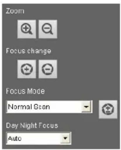
- Zoom: Click the Zoom In and Zoom Out buttons to adjust the apparent distance of the scene. After zooming the camera, re-focus the camera manually or automatically. For details, see Focus Change and Focus Mode below.
- Focus Change: Click the Focus In and Focus Out buttons to adjust the focus. To focus automatically, click the Auto Focus button.
- Focus Mode: Select Normal Scan, Regional Scan or Full Scan and then click the Start button to automatically adjust the camera focus. The Normal Scan mode focuses the camera the fastest. The Regional Scan mode focuses the area selected on the live view. The Full Scan mode performs a detailed checkup and applies the best focus.
-
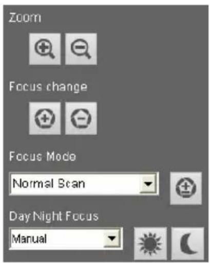
Day Night Focus: Saves focus settings for day mode and night mode. Select Auto to automatically focus. Select Close to disable the Day Night Focus function. To configure fixed settings for day mode and night mode, select Manual and follow the steps below:
-
Make sure the D/N is in Auto mode for the best effect. The following focus setting will be applied to the current D/N mode.
- Adjust the focus using the Focus In and Focus Out buttons and/or the Focus Mode function.
- Click Day Mode Save or the Night Mode Save button depending on the current D/N mode.
GeoVision
- Metering: Controls the camera's exposure. Select Normal for the camera to adjust exposure based on the full live view. Select Regional Metering for the camera to adjust exposure of specified zones. Draw directly on the live view and a block marked with “AE (automatic exposure)” appears. You can establish up to 4 zones. To remove the block, right-click the block and select Delete.
[Download] Allows you to install the programs from the hard drive.
text_image
Brightness Contrast Saturation Sharpness Gamma White balance Auto Flicker less 60 Hz Image Orientation Normal Slowest Shutter Speed Auto DIN Auto 3 Denoise Wide Dynamic Range Close Defog Close Low Lux Enhancement Close Metering NormalFigure 3-6A
text_image
Zoom Focus change Focus Mode Normal Scan Day Night Focus AutoFigure 3-6B
text_image
Zoom Focus change Focus Mode Normal Scan Day Night Focus ManualFigure 3-6C
Note:
- For GV-PTZ010D, Brightness, Contrast, Saturation, Sharpness, D/N, Slowest Shutter Speed, Wide Dynamic Range and Defog are not available.
- For GV-BX2600, Backlight Compensation, Wide Dynamic Range, Defog, Low Lux Enhancement, Denoise, Metering are not available. The WDR setting for GV-BX2600 is in Video Setting page (see Figure 4-2A, 4.1.1 Video Settings).
- Zoom, Focus Change, Focus Mode and Day Night Focus settings are only available for models with motorized varifocal lens.
- Denoise and Metering settings are only available for firmware V2.14 or later.
3.2.3 Snapshot of Live Video
To take a snapshot of live video, follow these steps:
- Click the Snapshot button (No. 5, Figure 3-3). The Save As dialog box appears.
- Specify Save in, type the File name, and select JPEG or BMP as Save as Type. You may also choose whether to display the name and date stamps on the image.
- Click the Save button to save the image in the local computer.
3.2.4 Video Recording
You can record live video for a certain period of time to your local computer.
- Click the File Save button (No. 6, Figure 3-3). The Save As dialog box appears.
- Specify Save in, type the File name, and move the Time Period slider to specify the time length of the video clip from 1 to 5 minutes.
- Click the Save button to start recording.
- To stop recording, click the Stop button (No. 2, Figure 3-3).
3.2.5 Picture-in-Picture and Picture-and-Picture View
The full screen mode provides two types of close-up views: Picture-in-Picture (PIP) and Picture-and Picture (PAP). The two views are useful to provide clear and detailed images of the surveillance area.
Picture-in-Picture View
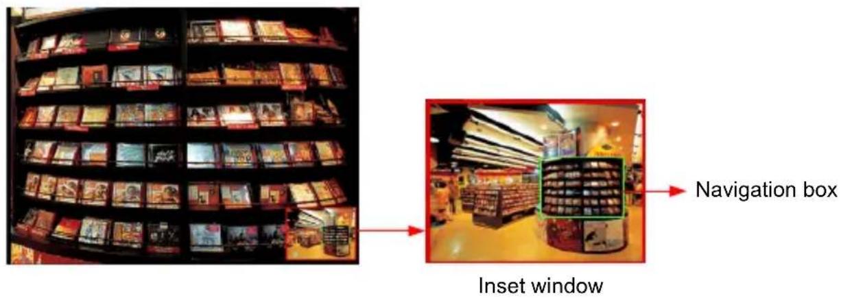
With the Picture in Picture (PIP) view, you can crop the video to get a close-up view or zoom in on the video.
text_image
Navigation box Inset windowFigure 3-7
- Right-click the live view and select PIP. An inset window appears.
- Click the insert window. A navigation box appears.
- Move the navigation box around in the inset window to have a close-up view of the selected area.
- To adjust the navigation box size, move the cursor to any of the box corners, and enlarge or diminish the box.
- To exit the PIP view, right-click the image and click PIP again.
Picture-and-Picture View
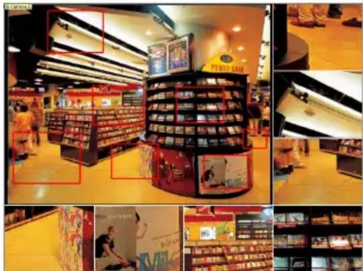
With the Picture and Picture (PAP) view, you can create a split video effect with multiple close-up views on the image. A total of 7 close-up views can be defined.
natural_image
Interior view of a supermarket with shelves, product displays, and promotional posters (no readable text or symbols)Figure 3-8
- Right-click the live view and select PAP. A row of three inset windows appears at the bottom.
- Draw a navigation box on the image, and this selected area is immediately reflected in one inset window. Up to seven navigation boxes can be drawn on the image.
- To adjust a navigation box size, move the cursor to any of the box corners, and enlarge or diminish the box.
- To move a navigation box to another area on the image, drag it to that area.
- To add more navigation boxes, to show or hide navigation boxes or to change the frame color of the navigation boxes, right-click the image, select Mega Pixel Setting and click one of these options:
■ Enable Add-Focus-Area Mode: Allows the user to add more navigation boxes on the image. This option is not available when 7 navigation boxes have been drawn.
■ Display Focus Area of PAP Mode: Displays or hides the navigation boxes on the image
■ Set Color of Focus Area: Changes the color of the box frames.
- To delete a navigation box, right-click the desired box, select Focus Area of PAP Mode and click Delete.
- To exit the PAP view, right-click the image and click PAP again.
3.2.6 Alarm Notification
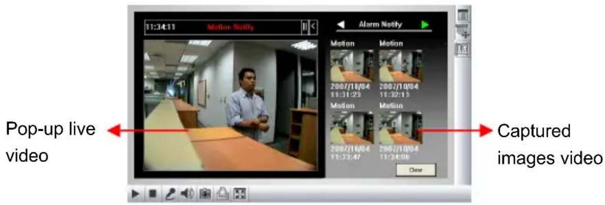
After input triggers and motion detection, you can be alerted by a pop-up live video and view up to four captured images.
text_image
11:34:11 Motion Notify Motion Motion 2007/10/04 2007/10/04 11:31:23 11:32:13 Motion Motion 2007/10/04 2007/10/04 11:23:47 11:24:08 Clear Pop-up live video Captured images videoFigure 3-9
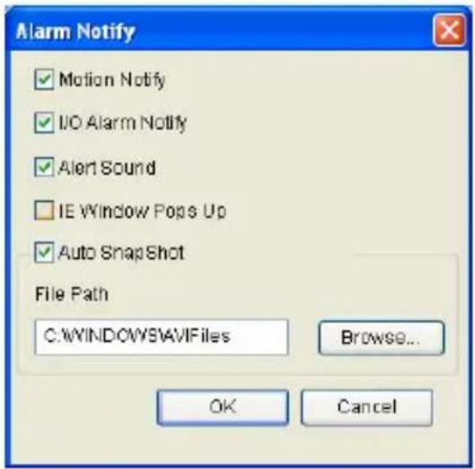
To configure this function, click the Show System Menu button (No. 9, Figure 3-3), and select Alarm Notify. This dialog box appears.
text_image
Alarm Notify ✓ Motion Notify ✓ I/O Alarm Notify ✓ Alert Sound ☐ IE Window Pops Up ✓ Auto SnapShot File Path C:\WINDOWS\AVIFiles Browse... OK CancelFigure 3-10
■ Motion Notify: Once motion is detected, the captured images are displayed on the control panel of the Live View window.
■ I/O Alarm Notify: Once the input device is triggered, the captured images are displayed on the control panel of the Live View window. For this function to work, the Administrator needs to install the input device properly. See 4.2.1 Input Setting.
■ Alert Sound: Activates the computer alarm on motion and input-triggered detection.
■ IE Window Pops up: The minimized Live View window pops up on motion and input-triggered detection.
■ Auto Snapshot: The snapshot of live video is taken every 5 seconds on motion and input-triggered detection.
■ File Path: Assigns a file path to save the snapshots.
3.2.7 Video and Audio Configuration
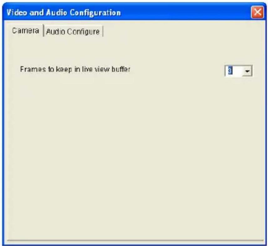
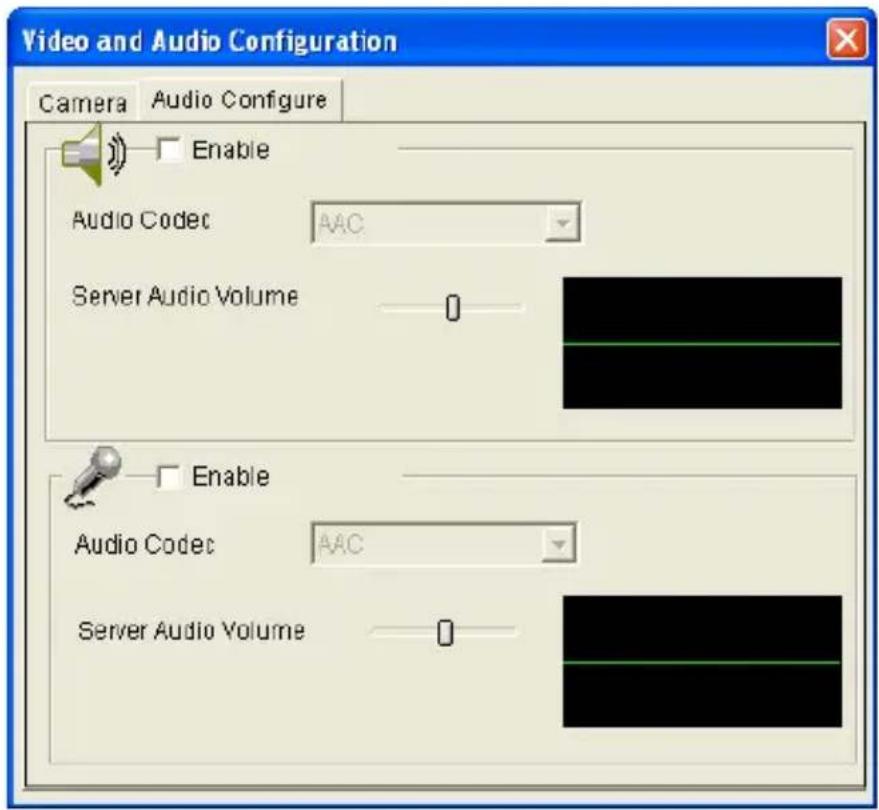
You can enable the microphone and speaker for two-way audio communication and adjust the audio volume. To change audio configuration, click the Show System Menu button (No. 9, Figure 3-3), and select Video and Audio Configuration.
■ Camera: Sets the number of frames to keep in live view buffer. Keeping more frames for live view buffer can ensure a smooth live view, but the live view will be delayed for the number of frames specified.
text_image
Video and Audio Configuration Camera | Audio Configure | Frames to keep in live view bufferFigure 3-11
■ Audio Configure: You can enable the microphone and speaker, and adjust the audio volume
text_image
Video and Audio Configuration Camera Audio Configure Enable Audio Codec AAC Server Audio Volume 0 Enable Audio Codec AAC Server Audio Volume 0Figure 3-12
3.2.8 Remote Configuration
You can upgrade firmware over the network. Click the Show System Menu button (No. 9, Figure 3-3), and select Remote Config. The Remote Config dialog box will appear.
[Firmware Upgrade] In this tab, you can upgrade the firmware over the Internet. For details, see Advanced Applications, Chapter 5.
3.2.9 Camera Name Display
To display the streaming name on the image, click the Show System Menu button (No. 9, Figure 3-3), and select Show Camera Name. Note this function is not available for GV-VD3700 / 5700.
3.2.10 Image Enhancement
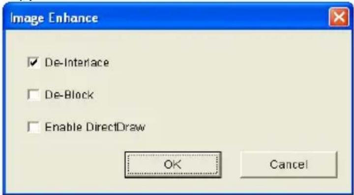
To enhance the image quality of live video, click the Show System Menu button (No. 9, Figure 3-3), and select Image Enhance. This dialog box appears.
text_image
Image Enhance ✓ De-Interface ☐ De-Block ☐ Enable DirectDraw OK CancelFigure 3-13
■ De-Interlace: Converts the interlaced video into non-interlaced video.
■ De-Block: Removes the block-like artifacts from low-quality and highly compressed video.
■ Enable DirectDraw: Activates the DirectDraw function.
3.2.11 Visual PTZ
Note this feature is only available in PTZ Camera and PT Camera.
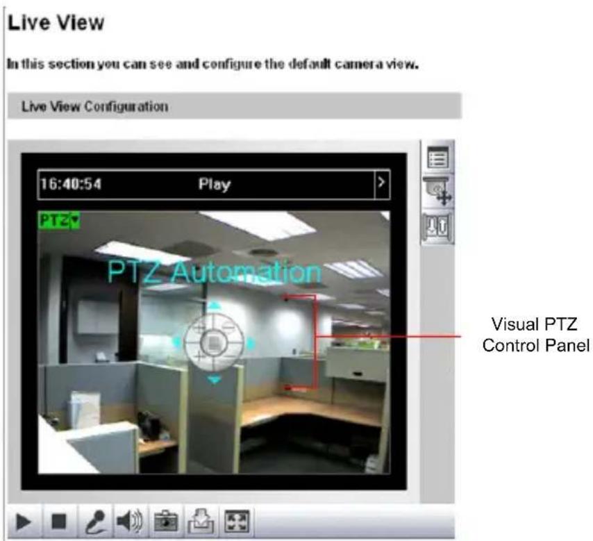
The Visual PTZ provides two types of PTZ control panels on live images for easy and direct PTZ operation.
Activating Visual PTZ
Click the PTZ Control button (No. 10, Figure 3-3) and select Visual PTZ. Alternatively right-click anywhere on the live view and select Visual PTZ.
text_image
Live View In this section you can see and configure the default camera view. Live View Configuration 16:40:54 Play > PTZ PTZ Automation Visual PTZ Control PanelFigure 3-14
text_image
1 2 3 4 5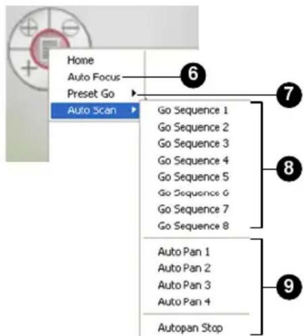
text_image
Home Auto Focus Preset Go Auto Scan Go Sequence 1 Go Sequence 2 Go Sequence 3 Go Sequence 4 Go Sequence 5 Go Sequence 6 Go Sequence 7 Go Sequence 8 Auto Pan 1 Auto Pan 2 Auto Pan 3 Auto Pan 4 Autopan StopFigure 3-15
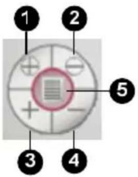
The Visual PTZ Panel provides the following features:
| No. | Name | Description |
| 1 | Zoom | InShortens the apparent distance between the camera and the view. |
| 2 | Zoom | OutLengthens the apparent distance between the camera and the view. |
| 3 | Focus | InAdjusts the sharpness of the camera view. |
| 4 | Focus | Out |
| 5 | Home | Brings the camera to the home point. |
| 6 | Auto | FocusAutomatically adjusts the sharpness of the camera view. |
| 7 | Preset | GoStarts a single movement in which the PTZ Camera moves towards a point in live view. |
| 8 | Go | SequenceStarts a series of movements in which the PTZ Camera moves towards at least two Preset points in live view. |
| 9 | Auto | PanStarts a horizontal movement of the PTZ Camera in live view. |
Setting Visual PTZ Panel
Click the button on the top left corner and select Visual PTZ, the following options will appear.
■ PTZ Control Type: Two types of visual PTZ control panels are available.
- Type 1: Appears only when a movement of the cursor is detected and disappears when it is static. When you place the cursor in one of the eight directions, i.e. up, down, left, right, left up, left down, right up and right down, a 5-level arrow appears. Click and hold onto the required level to move the camera. The speed level is indicated at the top right corner of the live view.
- Type 2: Appears with a click on the live view and disappears with the second click. As the cursor points to one of the eight directions, a 5-level arrow head appears. The further the arrow is away from the visual PTZ control panel, the faster the movement and vice versa. The speed level is indicated at the top right corner of the live view.
■ Set Color: Changes the color of the arrow line and the speed indicated at the top right corner of the live view. Alternatively, you can right-click the live view (with Visual PTZ enabled). Three colors are available: Red, Green and Blue.
■ Transparency: Changes the transparency level of the Visual PTZ Control Panel. Ten levels range from 10% (fully transparent) to 100% (fully opaque).
3.2.12 Digital PTZ
Note this function is only supported by GV-IPCAM H.264 firmware V2.06 and the GV-IPCAM H.265.
This function allows non-PTZ cameras to simulate PTZ movements on live view.
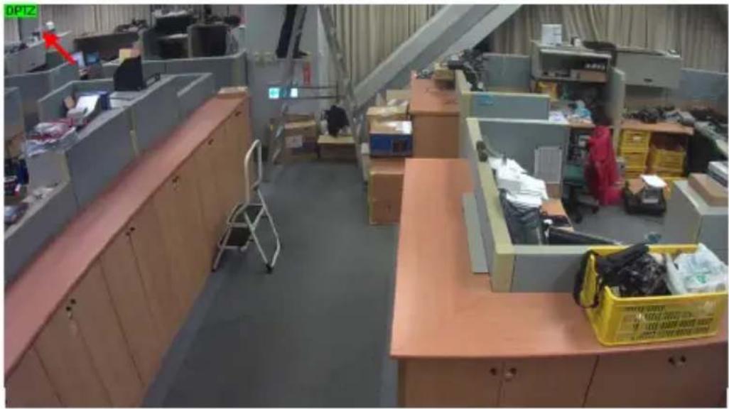
- Right-click the live view and select Digital PTZ. The live view is labeled with "DPTZ" at the top left corner.
natural_image
Interior view of an open-plan office with cubicles, desks, and storage bins (no visible text or symbols)Figure 3-16
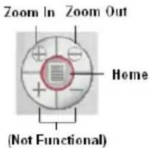
- To zoom in / out, move the cursor to the live view and click the corresponding buttons. To bring the view back to its default image, click Home.
text_image
Zoom In Zoom Out Home (Not Functional)Figure 3-17
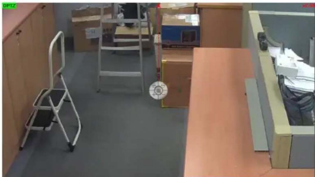
- To pan and tilt the view, zoom the image first and then click and hold the arrow on the image. The arrow appears when you place the cursor in one of the eight directions, i.e. up, down, left, right, left up, left down, right up and right down.
natural_image
Interior view of a dimly lit room with furniture and cardboard boxes (no visible text or symbols)Figure 3-18
- To adjust the transparency level of the control panel, click the green DPTZ button and select Transparency. Ten levels range from 10% (fully transparent) to 100% (fully opaque) are available.
Note: The Focus In / Out and the speed level are not functional for Digital PTZ.
3.2.13 I/O Control
Note this function is only supported by cameras with I/O function.
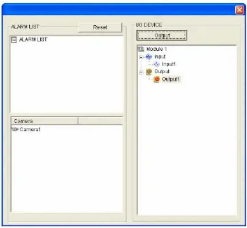
The I/O Control window provides a real-time graphic display of camera status, I/O status, and alarm events. Additionally, you can remotely force output to be triggered.
text_image
ALARM LIST Reset ALARM LIST Camera NO DEVICE Output Module 1 Input Input1 Output Output1 File Camera1Figure 3-19
- To display the I/O control window, click the I/O Control button (No. 11, Figure 3-3) and select I/O Control.
- The Alarm List is displayed in three levels. The first level indicates date, the second indicates time, and the third indicates alarm ID. Clicking the Reset button will clear the list.
- To trigger an output device, highlight an output and then click the Output button.
3.2.14 Visual Automation
Note this function is only supported by cameras with I/O function.
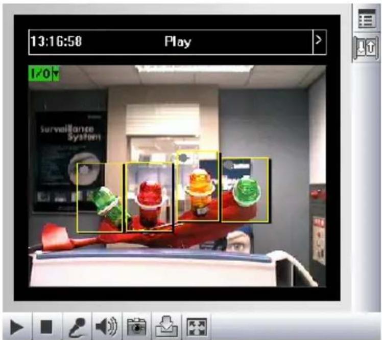
The Visual Automation allows you to change the current state of the electronic device by simply clicking on its image, e.g. turning the light ON. This feature is only available when the Visual Automation is set ahead by the Administrator. For details, see 4.1.6 Visual Automation.
text_image
13:16:50 Play 1/0 Surveillance SystemFigure 3-20
- To access this feature, click the I/O Control button (No. 11, Figure 3-3) and select Visual Automation.
- To change the style of the set areas, click the green I/O button on the top left corner. You will have these options:
■ Show All: Displays all set areas.
■ Rect Float: Embosses all set areas.
■ Set Color: Changes the frame color of all set areas
3.2.15 Network Status
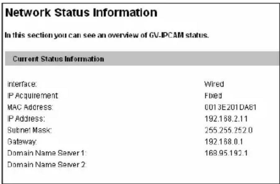
To view the network status, in the left menu, click Network and select Status.
text_image
Network Status Information In this section you can see an overview of GV-IPCAM status. Current Status Information interface: Wired IP Acquirement Fixed MAC Address: 0013E201DA81 IP Address: 192.168.2.11 Subnet Mask: 255.255.252.0 Gateway: 192.168.0.1 Domain Name Server 1: 168.95.192.1 Domain Name Server 2:Figure 3-21
Chapter 4 Administrator Mode
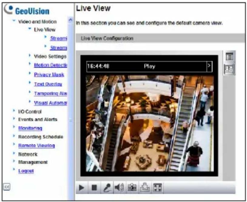
The Administrator can access the system configuration through the network. Eight categories of configurations are involved in the system configuration: Video and Motion, I/O Control or Digital I/O and PTZ, Events and Alerts, Monitoring, Recording Schedule, Remote ViewLog, Network and Management.
text_image
GeoVision Video and Motion Live View Streami Streami Video Settings Motion Detectic Privacy Mask Text Overlay Tamporting Ala Visual Automat I/O Control Events and Alerts Monitoring Recording Schedule Remote Viewlog Network Management Logout Live View In this section you can see and configure the default camera view. Live View Configuration 16:44:48 PlayFigure 4-1
List of Menu Options
Find the topic of interest by referring to the corresponding section listed below. The available options may vary among camera models.
| 4.1 Video and Motion | 4.1.1 Video Settings4.1.2 Motion Detection4.1.3 Privacy Mask4.1.4 Text Overlay4.1.5 Tampering Alarm4.1.6 Visual Automation |
| 4.2 Video Analysis | 4.2.1 Motion Detection4.2.2 Advanced Video Analysis4.2.2.1 Intruder4.2.2.2 People Count4.2.2.3 Loitering4.2.3 Unattended Object / Missing Object Detection4.2.4 Tampering Alarm |
| 4.3 Digital I/O and PTZ | 4.3.1 Input Settings4.3.2 Output Settings4.3.3 PTZ Settings |
| 4.4 Events and Alerts | 4.4.1 Email4.4.2 FTP4.4.3 Center V24.4.4 Vital Sign Monitor4.4.5 Backup Center4.4.6 Video Gateway/Recording Server4.4.7 ViewLog Server4.4.8 RTSP/ONVIF4.4.9 Speaker |
| 4.5 Monitoring | |
| 4.6 Recording Schedule | 4.6.1 Camera4.6.2 I/O Monitor |
| 4.7 Remote ViewLog | |
| 4.8 Network | 4.8.1 LAN4.8.2 Wireless-Client Mode4.8.3 Advanced TCP/IP4.8.4 UMTS Settings4.8.5 IP Filtering4.8.6 SNMP Settings |
| 4.9 Management | 4.9.1 Date and Time Settings4.9.2 Storage Settings4.9.3 User Account4.9.4 Log Information4.9.5 Tools4.9.6 Language |
4.1 Video and Motion
The GV-IPCAM can simultaneously process one video source in two different codec and resolutions. The dual-stream design benefits for lower bandwidth environment, allowing Streaming 2 to be set with lower resolution and codec for live streaming, and Streaming 1 set with highest resolution and H.264 / H.265 for best recording quality. Two setting pages Streaming 1 and Streaming 2 are provided for separate setup.
Comparison between Streaming 1 and Streaming 2:
| Video Setting Options Streaming 1 Streaming 2 | ||
| Watermark Setting | Yes | Not open for configuration. But settings in Streaming 1 are automatically applied to Streaming 2 |
| Audio in Source | ||
| Special View Setting | ||
| Video Resolution | Yes. Different resolutions can be applied to Streaming 1 and Streaming 2. | |
| Audio Settings | Yes | No |
| TV Out Yes | No | |
| Note:1. Audio In Source is only available in GV-PTZ010D.2. Audio Settings is not available for GV-PTZ010D.3. TV Out is only available for Box Camera, IR Arctic Box Camera, Vandal Proof IP Dome and Fixed IP Dome. | ||
This section includes the video image settings and how the images can be managed through Motion Detection, Privacy Mask, Text Overlay, Tampering Alarm, and Visual Automation.
4.1.1 Video Settings
Video Settings
In this section you can define compression art, broadcasting method and privacy mask.
Connection template
Fast (LAN, T1, Wireless 802.11a/g, ADSL-high speed.)
Video Signal Type
In this section you can configure camera's video signal, also the resolution and frame per second to be transmitted through the network
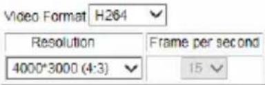
text_image
Video Format H264 Resolution Frame per second 4000*3000 (4:3) 15Bandwidth Management
In this section you can configure the bit rate used by video stream. When VBR (Variable Bit Rate) is selected, consistent image quality is achieved at the cost of varying bit rate. To set a consistent bit rate at the cost of varying image quality, select CBR (Constant Bit Rate).

text_image
VBR Quality Good Maximal Bit Rate 16 Mbps CBR Maximal Bit Rate 20480 Kbps Smart Streaming Static Scene Good Maximal Bit Rate 12 Mbps Dynamic Scene Good Maximal Bit Rate 16 Mbps Bitrate Reduction Level 254 Range: (30 ~ 254). * The bigger the lower bitrateRegion Of Interest (ROI)
In this section you can configure ROI.
Enable ROI Setting
GOP Structure and Length
In this section you can configure the composition of the video stream (GOP structure). Using I-Frame only will significantly increase the video quality as well as the bandwidth.
Group of Picture(GOP) Size 2.0 (seconds)
Figure 4-2A
H204 Video Entropy Coding Setting
In this section you can decide Video entropy coding for H.264 codec.
H.264 Entropy Encoding CAVLC
Record Settings
In this section you can configure pre-alarm and post-alarm settings.
Pre-alarm recording time
1 seconds
Post-alarm recording time
1 seconds with hard disk installed (1\~30)
Split interval
5 minutes
Recording Profile
Performance
Record audio
√ Write recording data into local storage
(If disabled, the camera will stop recording to local storage while live view is accessed through Web browsers or other applications.)
Text Overlay Settings
In this section you can set up texts to be overlaid on live view when viewing via GeoVision software.
Camera Name Camera
Overlay with:
Camera Name
Date
System Time
Name of the associated digital input
Text Overlay Settings (OSD)
In this section you can set up texts to be overlaid on live view.
Camera Name Camera
Font Size

Overlay with
Watermark Setting
In this section you can set Watermark function.
Enable
Figure 4-2B
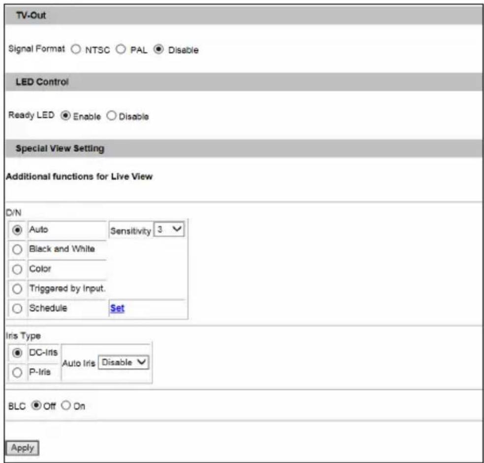
text_image
TV-Out Signal Format ○ NTSC ○ PAL ● Disable LED Control Ready LED ● Enable ○ Disable Special View Setting Additional functions for Live View D/N ● Auto Sensitivity 3 ○ Black and White ○ Color ○ Triggered by Input. ○ Schedule Set Iris Type ● DC-Iris Auto Iris Disable ○ P-Iris BLC ● Off ○ On ApplyFigure 4-2C
[Name] Rename the video stream. To display the name of video stream on the Live View window, see 3.2.9 Camera Name Display.
[Connection Template] Select the type of your network connection. Unless you select Customized, this option will automatically bring up the recommended video resolution, frame rate, bandwidth and GOP size.
[Video Signal Type] Select the video signal type, resolution and frame rate. Select among H.265, H.264 or MJPEG as the codec type. For details on the resolutions and frame rates of each camera model, see Appendix B.
Note that for all the cameras (except GV-PTZ010D), the resolution options available for sub stream vary with the resolution selected for its main stream. For example, if a 4:3 resolution is selected for the main stream in GV-EVD5100, three options, 960 x 720, 640 x 480 and 320 x 240 will be available for its sub stream.
Note: The Hardware WDR Support option (see Figure 4-2A) is only available for GV-BX2600. It produces clear live view when the scene contains very bright and very dark areas at the same time. This function is enabled by default. However, you will be prompted to disable the function when the camera records up to 60 frames per second.
For WDR Pro or WDR option of other cameras, see Camera Adjustment in 3.2.2 The Control Panel on the Live View Window to adjust the setting.
[Bandwidth Management] When using the H.264 / H.265 codec, it is possible to control the bitrate, which in turn allows the amount of bandwidth usage to be controlled.
■ VBR (Variable Bitrate): The quality of the video stream is kept as constant as possible at the cost of a varying bitrate. The bandwidth is much more efficiently used than a comparable CBR.
Set the image quality to one of the 5 standards: Standard, Fair, Good, Great and Excellent.
Maximal Bit Rate: When the actual bitrate exceeds the specified Maximal Bit Rate, the system will automatically lower its bitrate so as not to exceed it. Select one of the bitrates from the drop-down list or select Auto if you do not want to enable this function. The default maximal bitrate values are detailed as follows:
| Camera Type Default Max. Bitrate of VBR | ||
| 1.3 MP | Stream 1 6 | Mbit |
| Stream 2 4 | Mbit | |
| 2 MP | Stream 1 8 | Mbit |
| Stream 2 4 | Mbit | |
| 3 MP / 4 MP / 5 MP | Stream 1 | 12 Mbit |
| Stream 2 | ||
| 8 MP / 12 MP | Stream 1 | 16 Mbit |
| Stream 2 | ||
Note: For GV-BX2600, the default maximum bitrate for Stream 1 is set to 6 Mbit. When the video format of Stream 1 and 2 is set as MJPEG, the options for bitrate setting will be hidden automatically.
■ CBR (Constant Bitrate): CBR is used to achieve a specific bitrate by varying the quality of the H.264 / H.265 stream. Select one of the bitrates from the drop-down list.
■ Smart Streaming: When the option is enabled, the bitrates will be automatically reduced in static scenes, significantly maximizing bandwidth and lowering file size.
You can choose the image quality of Static Scene and Dynamic Scene to one of the 5 standards: Standard, Fair, Good, Great and Excellent. You can even choose the maximum bitrate to optimize the bandwidth.
Bitrate Reduction Level: The default value is 254. The bigger the value the more bitrates can be reduced in static scenes, thus saving the recording size.
Note: To enable Smart Streaming supported only by GV-BX12201 firmware V1.02 or later, it is required to use either GV-NVR V8.7 or GV-VMS V16.10.
[Region of Interest] Note this function is disabled by default and is not supported by GV-BX2600 and Target Series. Sets ROI (clarity) to specified regions on the live view for standalone GV-IP Cameras, GV-IP Cameras connecting to GV-System / GV-VMS or third-party software through ONVIF/RTSP. A total of 5 ROI can be set. This function is disabled by default.
Select Enable and click ROI Setting to configure:
- On the popup window, use your mouse and draw directly on the live view to specify a region.

text_image
ROI Property ● ROI Level High Delete Delete all ApplyFigure 4-3
- To set up a region with enhanced clarity, select ROI, select High, Medium or Low using the drop-down list and then drag on the image to outline a region.
- Click Apply to apply the configurations.
[GOP Structure and Length] Set the maximum number of seconds between every key frame.
[Video Slice Mode] Note this function is only supported by firmware V2.12 or earlier and is not supported by Target Series and GV-IPCAM H.265. Corrects the display mode of the camera when it is displayed on third-party NVR/DVR software and the live view is incomplete or broken. Select Single Slice or Multi Slice to display the live view. The default is Auto.
[H.264 Video Entropy Coding Setting] Note this function is not supported by GV-IPCAM H.265 and GV-BX12201. By default, the entropy coding is set to CAVLC. To change it to CABAC, click and select from the drop-down list.
[Record Settings] Note for GV-BX12201 firmware V1.02 or later and GV-IPCAM H.265, see Recording Settings in 4.5 Monitoring Settings to adjust the setting.
The alarm settings allow you to capture images before and/or after the motion or I/O events happen.
■ Pre-alarm recording time: Activates video recording before an event occurs. Set the recording time to 1 or 2 seconds. The recording is saved in the buffer of the camera.
■ Post-alarm recording time: Activates video recording onto the inserted memory card after an event occurs. Set the recording time from 1 to 30 seconds.
Split-interval (Max. Video Clip): Sets the maximum time length of each recorded file from 1 to 5 minutes.
Record Profile: Note this function is only available for firmware V2.14 or later. This setting is only applicable for recording to the camera's memory card. Select Performance to maximize the lifespan of the memory card by restricting the maximum bit rate to 4 Mbit and Sharpness value to 30. Select Quality to adopt your current settings.
■ Record audio: Activates audio recording when an event occurs.
Write recording data into local storage: Select this function for uninterrupted recording to the memory card while the live view is accessed through the Web interface or other applications. This option is enabled by default.
IMPORTANT: To ensure the quality of simultaneous recording and live view access, make sure you connect no more than two connections to the camera using Web interface or any other applications.
[Text Overlay Settings] Displays camera name, date, and/or time on the live view and recorded videos when viewing through GeoVision software.
■ Camera Name: Type the camera name.
■ Overlay with: Select one or more of the options below to be overlaid on the live view and recorded videos.
- Camera Name
Date
- System Time
- Name of the Associated Digital Input: Note this option is only supported by cameras with I/O function.
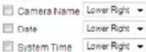
[Text Overlay Settings (OSD)] Note this function is not supported by GV-BX2600.
Displays camera name, date, and/or time on the live view and recorded videos when viewing through GeoVision software and third-party software through ONVIF and RTSP.
■ Name: Type the camera name.
■ Font Size: Select the font size using the drop-down list.
■ Overlay with: Select one or more of the options below to be overlaid on the live view and recorded videos. Use the drop-down list to select the display position.
- Camera Name
Date - System Time
[Watermark Setting] Note this function is not supported for Target Series. Enable this option to watermark all recordings. The watermark allows you to verify whether the video has been tampered while it was recorded. See 6.4 Verifying Watermark.
[Audio In Source] Note this function is only available in GV-PTZ010D which contain a built-in microphone and also allow you to install an external microphone.
■ Built-in Microphone: Enable the built-in microphone to record sounds. By default the option is enabled.
■ External Microphone: Enable the externally connected microphone to record sounds.
[TV Out] Note this function is only available for the camera with TV-out connector. Select the signal format of the Video Output on the camera as either NTSC or PAL.
Note:
- For smooth display of Box Camera, IR Arctic Box Camera, Fixed IP Dome and Vandal Proof IP Dome on monitor, the video resolution must be 1280 x 1024 or lower. If dual streams are enabled, the sub stream must be set as 640 x 480.
- The resolution of GV-EFD2101/3101/5101 and GV-EVD2100/3100/5100 on monitor is universally set to D1.
[LED Control] Note this function is not available for GV-PTZ010D.
■ Ready LED: Select Disable if you do not wish to use the Status LED.
■ LAN LED, WAN LED, Monitoring LED: Note this option is only available in Advanced Cube Camera. Select Disable if you do not wish to use the LEDs. For details on LED status, see Overview in the corresponding Hardware Manual.
■ Alarm LED: Sets the white illumination LED in Advanced Cube Camera. The LED is enabled by default.
- Auto: Select Auto for the white illumination LED to illuminate the scene automatically when the PIR sensor detects any motion within 5 meters.
- Sensitivity: Set the sensitivity for low light detection. The higher the value, the easier the white illumination LED is to be triggered. The default value is 5.
The Interval between triggering: Select the duration for the white illumination LED to light up at full intensity. If a motion persists over the specified period, the white illumination LED will light up with less intensity. This option is designed to keep the camera temperature within its precautious range. The default value is 60 seconds.
Off: Select to disable the white illumination LED.
[Special View Setting] Note this function is not available for GV-BX2600.
■ D/N: Sets the sensitivity of day-night mode switch. The higher the sensitivity value, the more sensitive the switch is from day mode to night mode. The default value is 5.
- Auto: Select Auto for the camera to detect the amount of light present and automatically switch to monochrome in a poorly-lit scene. Move the slider to adjust the sensitivity level from 0 to 10.
- Black and White: Select this option for the live view to be in monochrome.
- Color: Select this option for the live view to be in color.
- Triggered by Input: For GV-BX12201 firmware V1.02 or later, select this option to switch between day mode and night mode once the input device (e.g. sensor or button) is triggered.
- Schedule: For GV-BX12201 firmware V1.02 or later, select this option to determine specific period(s) of time when day mode is activated. See 4.6.1 Recording Schedule Settings for the details on the setting of the schedule.
■ IR Check Function: Note this option is only available for Box Camera (except GV-BX2600). This function determines whether the surveillance area is illuminated by an externally installed infrared illuminator.
- Off: The default setting. The infrared illuminator will be constantly off. It is advisable to enable this option when the color temperature of outdoor lighting is 6000 K or above.
On: The infrared illuminator will be constantly on. - Trigger by Input / Trigger IR by D/N: Select this option for the infrared illuminator to turn on under low light and turn off under sufficient light.
Note:
- If an infrared illuminator is installed for outdoor surveillance, it is suggested to use the Trigger by Input or the Trigger IR by D/N function to avoid incorrect judgment of lighting and hence the action of the IR cut filter. See Infrared Illuminators in the Hardware Manual.
- If you select Trigger by Input / Trigger IR by D/N option, make sure you have set D/N as Auto and configured its sensitivity level.
- Iris Type: Note this function is not supported for the camera with fixed lens or fixed iris. This field shows the iris type (DC-Iris or P-Iris) of your GV-IP Camera.
- Auto Iris: The option is designed for auto iris lens (DC-Iris or P-Iris). Enable the auto iris function when the scene appears fuzzy and the Flicker Less function does not help to improve the situation.
■ BLC: Note this function is not supported by GV-BX2600. Select On to enable Backlight Compensation (BLC). This function is used to adjust the color intensity of scenes with strong light at the background.
Note: To access the BLC function in PTZ camera, see Other, Image Settings in the Hardware Manual.
■ IR Light: Note this function is only available for Target Series, Ultra Box Camera, IR Arctic Box Camera, Bullet Camera, Ultra Bullet Camera, PT Camera, Vandal Proof IP Dome and Fixed IP Dome. Select Auto for automatic switch between day mode and night mode depending on the amount of light detected. Select Off to completely disable IR LEDs.
■ Noise Reduction: Note this function is only supported by GV-EVD5100 and GV-EFD5101. Reduces image noise especially under low-light conditions.
Note: When the Noise Reduction is enabled, the frame rate will be affected. For details see Note for GV-EVD5100 / EFD5101 at the beginning of the manual.
4.1.2 Motion Detection
Motion detection is disabled by default except for GV-PTZ010D.
Note: GV-BX2600 has its independent motion detection setting. For details, see 4.2 Video Analysis.
Motion detection is used to generate an alarm whenever movement occurs in the video image. You can configure up to 8 areas with different sensitivity values for motion detection. Set up at least one area to enable this function.
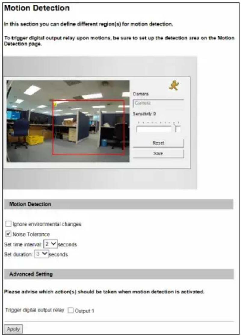
text_image
Motion Detection In this section you can define different region(s) for motion detection. To trigger digital output relay upon motions, be sure to set up the detection area on the Motion Detection page. Camera Camera Sensitivity: 9 Reset Save Motion Detection Ignore environmental changes Noise Tolerance Set time interval: 2 seconds Set duration: 3 seconds Advanced Setting Please advise which action(s) should be taken when motion detection is activated. Trigger digital output relay Output 1 ApplyFigure 4-4
- Select the desired sensitivity by moving the slider. There are ten values. The higher the value, the more sensitive the camera is to motion.
- Drag an area on the image. Click Add when you are prompted to confirm the setting.
- To create several areas with different sensitivity values, repeat steps 1 and 2.
- Click Save to save the above settings.
-
Click Reset to delete all the selected areas.
-
If you want to detect motion using the PIR sensor (for Advanced Cube Camera only), select Use PIR to detect motion.
- If you want to ignore environmental changes such as rain or snow, select Ignore environmental changes.
- The Noise Tolerance function is enabled by default. It ignores video noise when the light intensity changes.
- To set a period of time before a motion is to be detected, select Set time interval. The choices available range from 0-3 second(s).
- To set a period of time for a motion to last, select Set duration. The choices available range from 1-5 second(s).
- If you want to trigger the alarm output when motion is detected, select Output 1 and click the Apply button. To activate the output settings, you must also start Input monitoring manually or by schedule. For related settings, see 4.5 Monitoring.
Note: Set time interval and Set duration are only supported by GV-BX12201 firmware V1.02 or later.
4.1.3 Privacy Mask
The Privacy Mask function is used to block out sensitive areas on live view and recorded clips for cameras connecting to GeoVision software. This feature is ideal for locations with displays, keyboard sequences (e.g. passwords), and for anywhere else you don't want sensitive information visible.
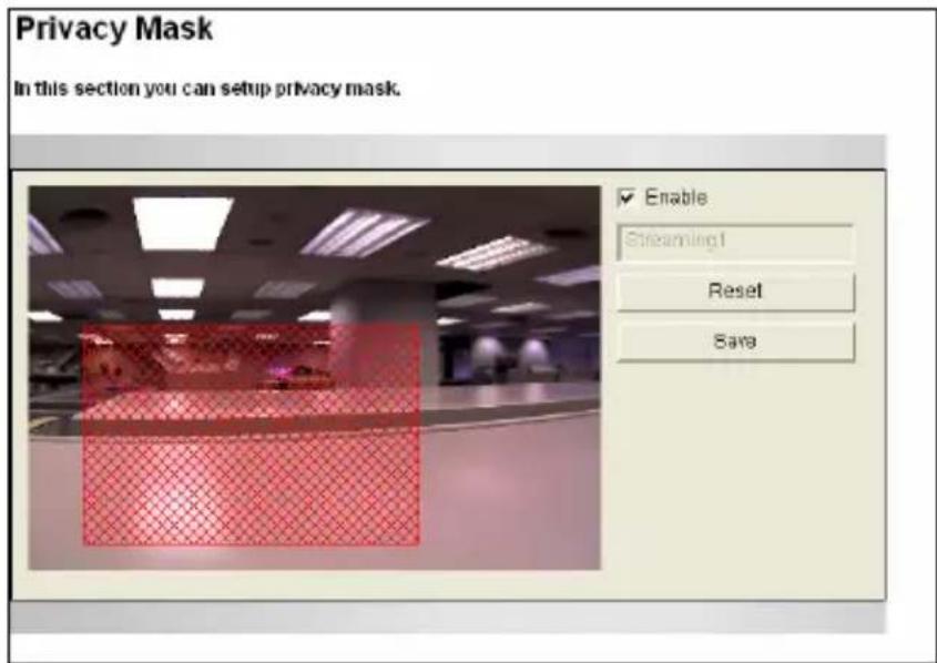
text_image
Privacy Mask In this section you can setup privacy mask. Enable Streaming1 Reset SaraFigure 4-5
- Select the Enable option.
- Drag the area(s) where you want to block out on the image. Click Add when you are prompted to confirm the setting.
- Click the Save button to save all the settings.
4.1.4 Text Overlay
The Text Overlay allows you to overlay any text in any place on the camera view. Up to 16 text messages can be created on one camera view. The overlaid text will be saved in the recordings.
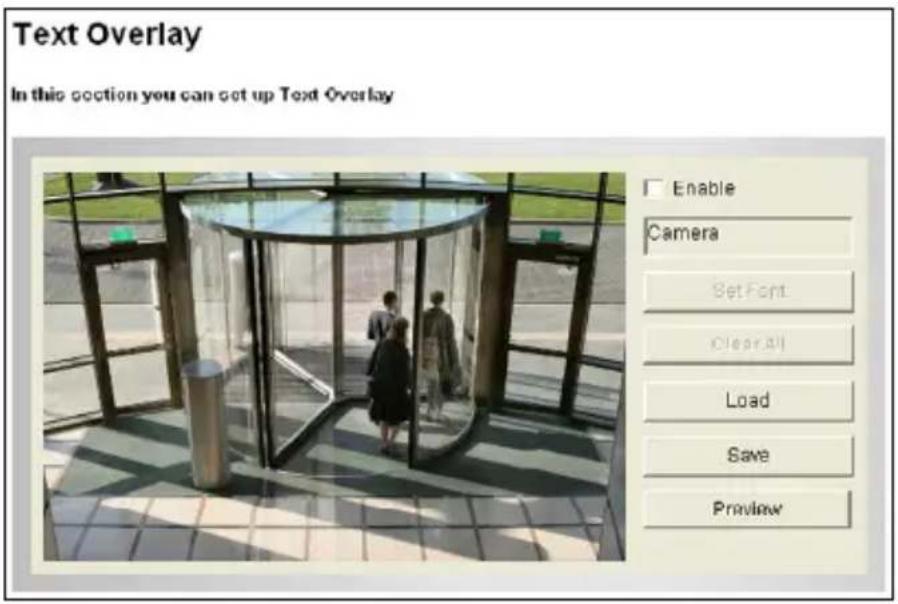
text_image
Text Overlay In this section you can set up Text Overlay Enable Camera Set Font ClearAll Load Save PreviewFigure 4-6
- Select the font, font style and font size in a pop-up window.
- Select the Enable option.
- Click any place on the image. This dialog box appears.
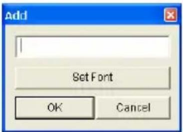
text_image
Add Set Font OK CancelFigure 4-7
- Type the desired text, and click OK. The text is overlaid on the image.
- Drag the overlaid text to a desired place on the image.
GeoVision
- Click Set Font to modify the font settings.
- Click Save to apply the settings, or click Load (Undo) to revert to the last saved setting.
- Click Preview to see how the text will appear on the image. Click Close to end the preview.
4.1.5 Tampering Alarm
Note this function is not available for PTZ Camera and PT Camera.
Tampering Alarm is used to detect whether a camera is being physically tampered. An alarm can be generated when the camera is moved, covered up, or out of focus. The alarm types include triggered the output device, e-mail alert and notifying the connected GV-Center V2, GV-Vital Sign Monitor and GV-System / GV-VMS.
Note:
- This function is not available for PTZ Camera and PT Camera.
- GV-BX2600 has its independent Tampering Alarm setting. For details, see 4.2 Video Analysis.
To establish the tampering alarm, set up at lest one alarm type:
- To trigger the output device when a tampering event occurs, enable the output setting and select Tampering Alarm. See 4.3.2 Output Settings.
- To trigger the e-mail alert when a tampering event occurs, enable the e-mail setting and select Tampering Alarm. See 4.4.1 E-Mail.
- To notify GV-Center V2, GV-Vital Sign Monitor and GV-System / GV-VMS when a tampering event occurs, enable the connection to these systems. See 4.4.3 Center V2, 4.4.4 Vital Sign Monitor, 7.1 Setting up an IP Camera on GV-System, and 7.2 Setting Up IP Cameras on GV-VMS.
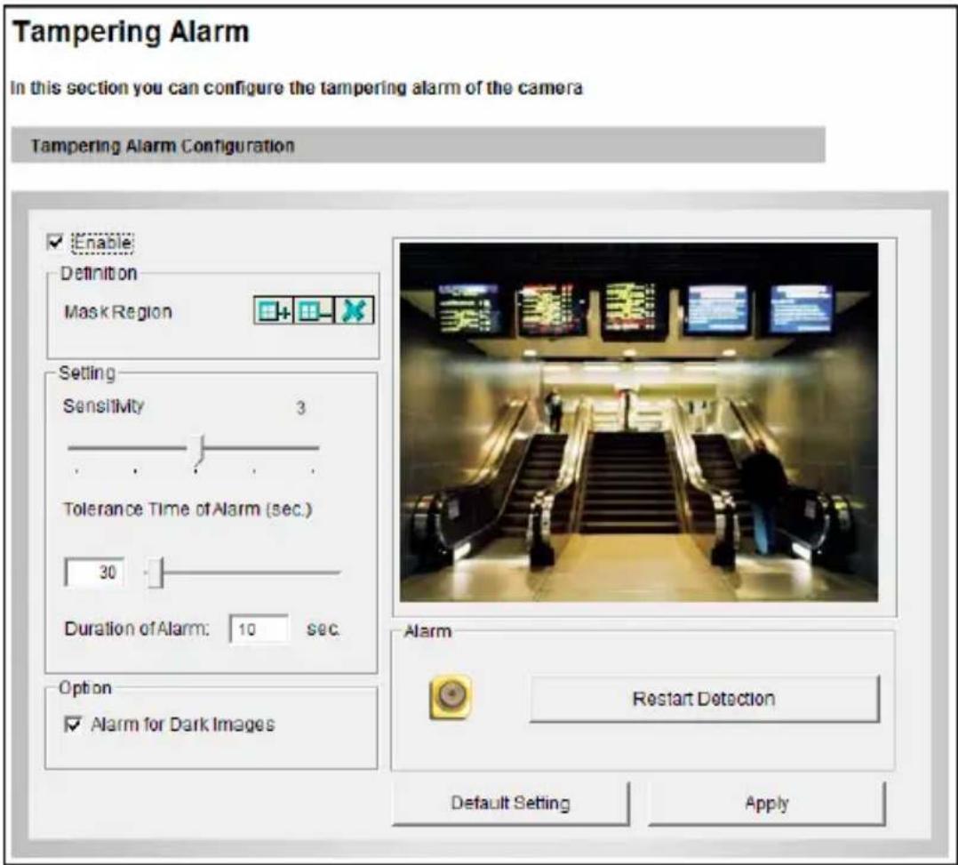
text_image
Tampering Alarm In this section you can configure the tampering alarm of the camera Tampering Alarm Configuration Enable Definition Mask Region Setting Sensitivity 3 Tolerance Time of Alarm (sec.) 30 Duration of Alarm: 10 sec. Option Alarm for Dark Images Alarm Restart Detection Default Setting ApplyFigure 4-8
To configure the tampering alarm:
- Select the Enable option.
- If you want the camera to ignore any movement or scene change in certain areas, click the button to drag areas on the camera view.
- Select the desired detection sensitivity by moving the slider. The higher the value, the more sensitive the camera is to scene changes.
- In the Tolerance Time of Alarm field, specify the time length allowed for scene changes before an alarm is generated.
-
In the Duration of Alarm field, specify the duration of the alarm after which the triggered output device will be turned off.
-
To trigger an alarm when the scene turns dark, e.g. when the lens of camera is covered, make sure the Alarm for Dark Images option is enabled. By default, this function is enabled.
- Click Apply to save all the settings.
- Start monitoring to enable the function. To have output alarm, it is required to start Input monitoring. See 4.5 Monitoring.
When the camera has been tampered, the output device can be activated. To turn off the output device immediately, return to this setting page, and click Restart Detection.
4.1.6 Visual Automation
Note this function is only supported by cameras with I/O function.
This intuitive feature helps you automate any electronic device by triggering the connected output device. When you click on the image of the electronic device, you can simply change its current state, e.g. light ON.
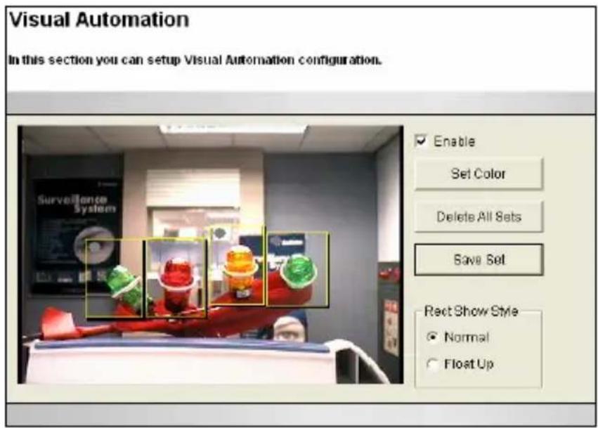
text_image
Visual Automation In this section you can setup Visual Automation configuration. Enable Set Color Delete All Sets Save Set Rect Show Style Normal Float UpFigure 4-9
- Select the Enable option.
- Drag an area on the image of the electronic device. This dialog box appears.
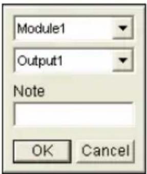
text_image
Module1 Output1 Note OK CancelFigure 4-10
- Assign the connected module and output device. In the Note field, type a note to help you manage the device. Click OK to save the settings.
- To change the frame color of the set area, click the Set Color button.
- To emboss the set area, select Float Up; or keep it flat by selecting Normal.
- Click the Save Set button to apply the settings.
- To perform the function, see 3.2.14 Visual Automation.
4.2 Video Analysis
Note the Video Analysis functions in this section are only available for GV-BX2600 and only work with the surveillance system GV-VMS V15.10 or later.
Video Analysis provides real-time video capture for detection of temporary occurrences or events of interest. You can use the video image to identify motion, find and trace objects, and even produce alarms on unusual activities.
IMPORTANT: To enable the "Video Analysis on Camera" function on GV-VMS, the following setting is required on GV-VMS in advance:
- Click Home, click Toolbar, click Configure, and select Video Process.
- In the Setup dialog box, select IPCVA, select the camera(s), and select Setting.
- Select which video analysis to process on the camera.
The status bar on every Video Analysis page presents the current state of the camera's view being displayed on screen. It also includes controls that allow you to locate any detection region which you would like to edit or delete.
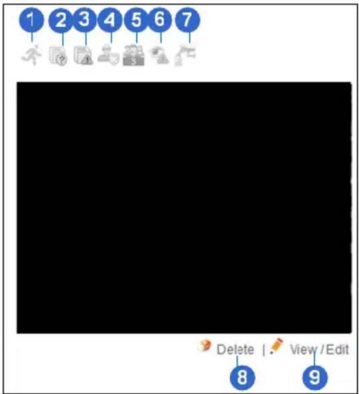
text_image
1 2 3 4 5 6 7 Delete | . View / Edit 8 9Figure 4-11
| No. | Name Description |
| 1 | MotionDetectionThe icon turns red when motion is detected.For details, see 4.2.1 Motion Detection. |
| 2 | Missing ObjectTheicon flashes when the target object is missing from the camera view. For details, see 4.2.3 Missing Object Detection. |
| 3 | Unattended Object | The iconflashes when an unattended object stays within the camera view. For details, see 4.2.3 Unattended Object. |
| 4 | Intruder | The iconflashes when an intruder crosses the defined regions. For details, see 4.2.2.1 Intruder. |
| 5 | People Count | The iconflashes when the target object crosses the defined regions. For details, see 4.2.2.2 People Count. |
| 6 | Loitering | The iconflashes when motion has been detected within a certain time frame. For details, see 4.2.2.3 Loitering. |
| 7 | Tampering Alarm | The iconflashes when the camera is being physically tampered. For details, see 4.2.4 Tampering Alarm. |
| 8 | Delete | Removes an unwanted detection area. After you click Delete, a X icon will appear on the defined area, e.g..Click the X icon to remove a defined area. |
| 9 | View / Edit | Displays the current settings of a detection region. After you click View / Edit, a pen icon will appear on the defined area, e.g..Click the pen icon to display its elated setting page to the left side of the live view. |
4.2.1 Motion Detection
Whenever movement is observed in the detection region, you will be alerted by an alarm or a notification. The alarm output will be set off, e-mail and FTP upload will be triggered, and the connected surveillance system GV-VMS, GV-Center V2 and GV-Vital Sign Monitor will record the event.
You can configure up to 3 areas with different sensitivity values for motion detection.
- From the Video Analysis drop-down list, select Motion Detection. This page appears.
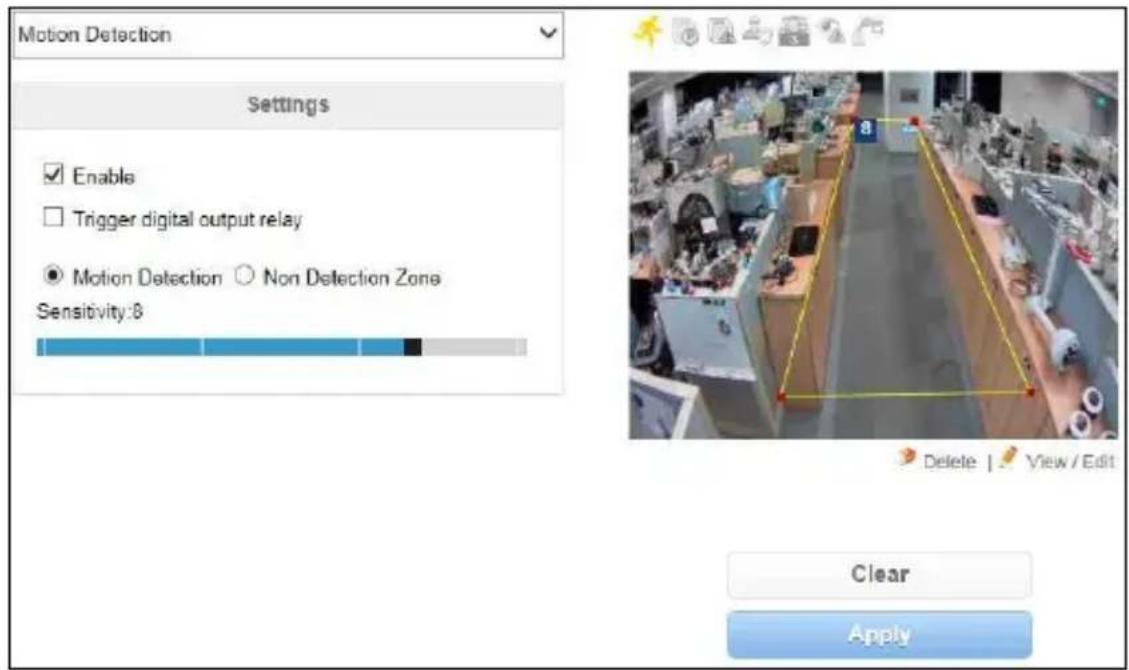
text_image
Motion Detection Settings Enable Trigger digital output relay Motion Detection ○ Non Detection Zone Sensitivity:8 Delete | View / Edit Clear ApplyFigure 4-12
-
Select Enable.
-
If you want to invoke an alarm output when motion occurs, select Trigger digital output relay. For this function, you need to set up an output device in advance, see 4.3.2 Output Settings.
-
To define a detection region:
A. Use the slider to set a desired sensitivity level for the detection region you want to define in step 4B. The sensitivity levels range from 1 to 10, with 8 as default. The higher the level, the more sensitive the camera is to motion.
B. On the live view, draw a detection area. To draw an irregular shape, drag one or more of the red dots that outline the box until the line is in the shape that you want.
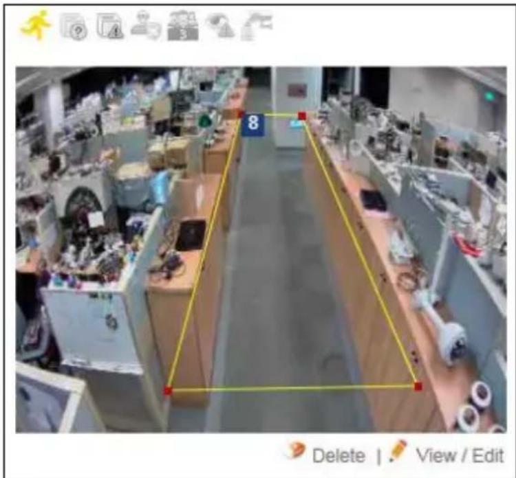
text_image
8 Delete | View / EditFigure 4-13
C. Click Fix to confirm your setting.
D. To create several areas with different sensitivities, repeat steps 4A and 4B.
E. To clear any defined area, click Delete under the image, and click the X icon to remove it. Click again to return to the setting.
- To ignore motion detection in a certain area:
A. Select Non Detection Zone and draw an area to mask off an unwanted area on the live view.
B. Click Fix to confirm your setting.
C. To create several non detection zones, repeat steps 5A and 5B.
- To activate motion detection at specific time periods each day, create a schedule.
■ Span 1- Span 3: Set a different time frame during the day. Each day can be divided into 3 time frames, represented by Span 1 to Span 3.
■ Only Saturday: Enable the motion detection function only on Saturday.
■ Only Sunday: Enable the motion detection function only on Sunday.
■ Special Day: Enable the motion detection function on a specified day.
- Click the Apply button to start motion detection.
- To trigger the alarm output when motion is detected, enable Input monitoring manually or by schedule. To configure the input monitoring, see 4.5 Monitoring.
- To trigger the e-mail alert and upload captured images to FTP server when motion is detected, configure e-mail and FTP servers and select Motion Detection alarm. See 4.4.1 E-Mail and 4.4.2 FTP.
- To notify GV-Center V2, GV-Vital Sign Monitor and GV-VMS when motion is detected, enable the connection to these systems. See 4.4.3 Center V2, 4.4.4 Vital Sign Monitor and 7.2 Setting up IP Cameras on GV-VMS.
In GV-VMS, when motion is detected on the camera, you will see the log event "Motion" as illustrated below.
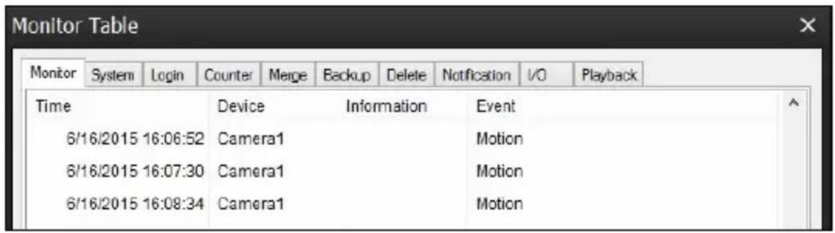
text_image
Monitor Table Monitor System Login Counter Merge Backup Delete Notification I/O Playback Time Device Information Event 6/16/2015 16:06:52 Camera1 Motion 6/16/2015 16:07:30 Camera1 Motion 6/16/2015 16:08:34 Camera1 MotionIMPORTANT: It is required to enable the "Video Analysis on Camera" function on GV-VMS in advance. See Important note on page 78.
4.2.2 Advanced Video Analysis
From the Video Analysis drop-down list, select Advanced Video Analysis. Advanced Video Analysis can perform a variety of tasks for security purpose and other events of interest. Intruder detects when an object enters into the defined region. People Count records objects or people of interest moving through the defined areas. Loitering triggers an event when an object remains in the defined place for a protracted time.
Note: You can only operate one function at a time.
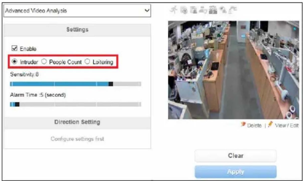
text_image
Advanced Video Analysis Settings Enable Intruder ○ People Count ○ Loitering Sensitivity:8 Alarm Time :5 (second) Direction Setting Configure settings first Clear ApplyFigure 4-14
4.2.2.1 Intruder
When any object moves into and out of the two defined regions, the event will be recorded to the connected surveillance system GV-VMS for later retrieval.
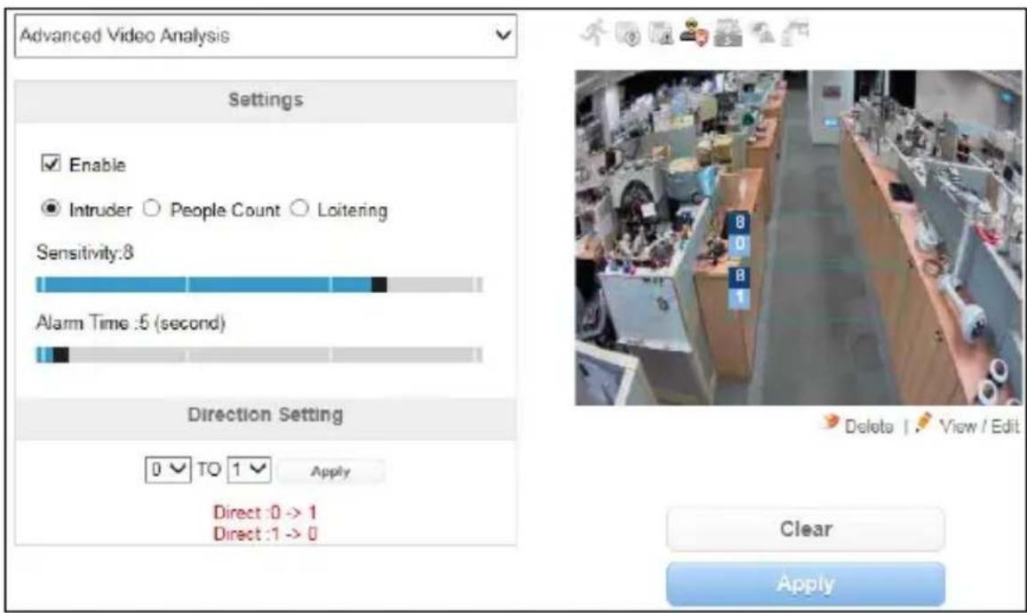
text_image
Advanced Video Analysis Settings Enable Intruder ○ People Count ○ Loitering Sensitivity:8 Alarm Time :5 (second) Direction Setting 0 TO 1 Apply Direct :0 -> 1 Direct :1 -> 0 Delete | View / Edit Clear ApplyFigure 4-15
- Select Enable.
- Select Intruder to set up the intruder alarm settings.
- Use the Sensitivity slider to increase or decrease the detection sensitivity of the region you want to define in step 4. The sensitivity levels range from 1 to 10, with 8 as default.
- Draw two areas for intruder detection.
A. On the live view, draw a detection area. To draw an irregular shape, drag one or more of the red dots that outline the detection region until the line is in the shape that you want. See Figure 4-13.
B. Click Fix to confirm your setting.
C. To draw the 2^nd detection area, repeat steps 4A and 4B. Each detection region is numbered.
D. To clear any defined area, click Delete under the image, and click the X icon to remove it. Click again to return to the setting.
- To configure the intrusion direction, select the detection direction from 0 to 1, 0 to 1, or both in Direction Setting. The alarm sets off when the intruder moves through the first detection area into the second area in the defined direction, or vice versa.
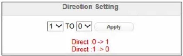
text_image
Direction Setting 1 TO 0 Apply Direct :0 -> 1 Direct :1 -> 0Figure 4-16
-
Use the Alarm Time slider to specify the time length required for the intrusion alarm to be triggered when the system detects any intruders within the defined areas. The default setting is 5 seconds.
-
To activate intruder detection settings at specific time periods each day, create a schedule. For details, see Step 6 in 4.2.1 Motion Detection.
-
Click the Apply button to start intruder detection.
In GV-VMS, when the event is detected on the camera, you will see the log "Intruder" as illustrated below.
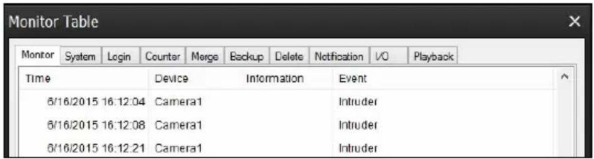
text_image
Monitor Table Monitor System hemg Login Counter Merge Backup Delete Notification V0 Playback Time Device Information Event 6/16/2015 16:12:04 Camera1 Intruder 6/16/2015 16:12:08 Camera1 Intruder 6/16/2015 16:12:21 Camera1 IntruderFor details on how to connect to GV-VMS, see 7.2 Setting up IP Cameras on GV-VMS.
IMPORTANT: It is required to enable the "Video Analysis on Camera" function on GV-VMS in advance. See Important note on page 78.
4.2.2.2 People Count
People Count counts the number of moving objects, such as vehicles, people or animals, between two specific points under the surveillance area.
The counting results will be recorded to the connected surveillance system GV-VMS for later retrieval.
Note: For counting accuracy, the camera should be installed in a vertical position and at least 3 meters from the ground.
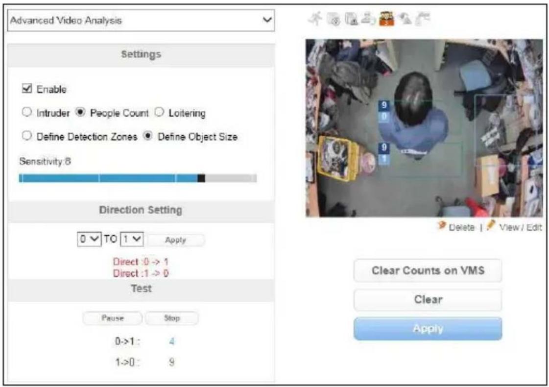
text_image
Advanced Video Analysis Settings Enable Intruder ● People Count ○ Loitering Define Detection Zones ● Define Object Size Sensitivity:8 Direction Setting 0 TO 1 Apply Direct :0 -> 1 Direct :1 -> 0 Test Pause Stop 0->1 : 4 1->0 : 9 Clear Counts on VMS Clear ApplyFigure 4-17
-
Select Enable.
-
Select People Count to set up the counter.
-
Draw two detection areas for object counting.
A. Select Define Detection Zones to define the detection area.
B. Use the Sensitivity slider to increase or decrease the detection sensitivity of the area you want to define in step 3C. The sensitivity levels range from 1 to 10, with 8 as default. The higher the level, the more sensitive the camera is to motion.
E. On the live view, outline a detection area. To draw an irregular shape, drag one or more of the red dots that outline the box until the line is in the shape that you want. See Figure 4-13.
C. Click Fix to confirm your setting.
D. Repeat steps 3A to 3D to draw the 2^nd detection area. Each detection area is numbered.
E. To clear any defined area, click Delete under the image, and click the X icon to remove it. Click again to return to the setting.
- Select Define Object Size to define the size of the target object to be detected.
A. On the live view, outline an area matching 5 % bigger than the normal size of the target object. You can drag one or more of the red dots that outline the area until the line is in the shape that you want.
B. Click Fix to confirm your setting.
C. Move the defined size of object to the place that will not obstruct the live view.
-
Select the detection direction from 0 to 1, 0 to 1, or both in Direction Setting. The object will be counted as 1 when moving through the first detection area into the second area in the configured direction or vice versa.
-
Click Apply
- To test your counting settings, click Start to begin testing. Notice how the number changes under the Test section when objects move through the detection areas.
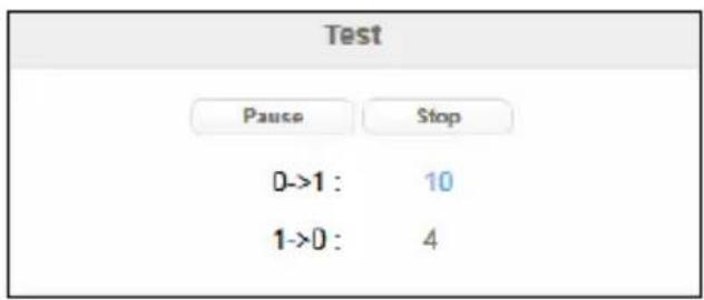
text_image
Test Pause Stop 0->1 : 10 1->0 : 4Figure 4-18
- To activate people count settings at specific time periods each day, create a schedule. For details, see step 6 in 4.2.1 Motion Detection.
- Click Apply again to start counting.
In GV-VMS, the counting results are displayed on the live view and recorded to the System Log. If you want to clear the count results on the live view, click Clear Counts on VMS Clear Counts on VMS and then Apply Apply .
The log event in GV-VMS may look like this figure with the counting results for In and Out:
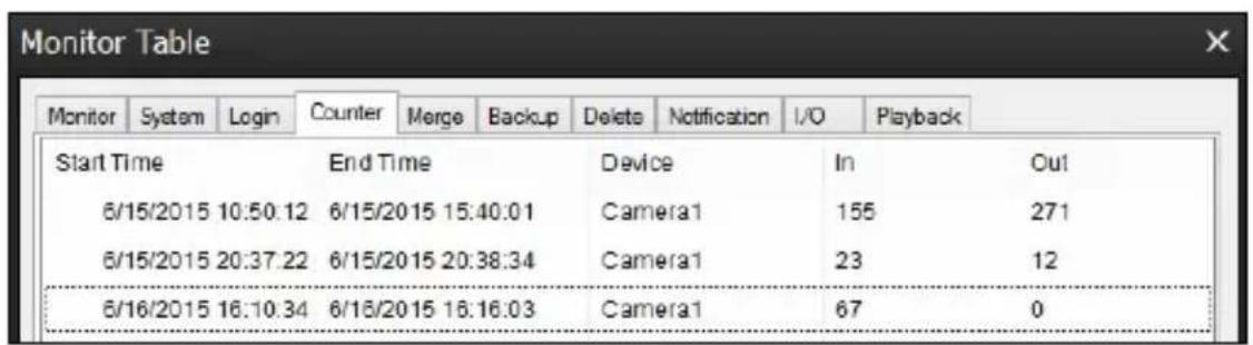
text_image
Monitor Table Monitor System Login Counter Merge Backup Delete Notification I/O Playback Start Time End Time Device In Out 6/15/2015 10:50:12 6/15/2015 15:40:01 Camera1 155 271 6/15/2015 20:37:22 6/15/2015 20:38:34 Camera1 23 12 6/16/2015 16:10:34 6/16/2015 16:16:03 Camera1 67 0For details on how to connect to GV-VMS, see 7.2 Setting up IP Cameras on GV-VMS.
IMPORTANT: It is required to enable the "Video Analysis on Camera" function on GV-VMS in advance. See Important note on page 78.
4.2.2.3 Loitering
After movement occurs at a specific area and exceeds the defined time threshold, the event will be recorded to the connected surveillance system GV-VMS for later retrieval.
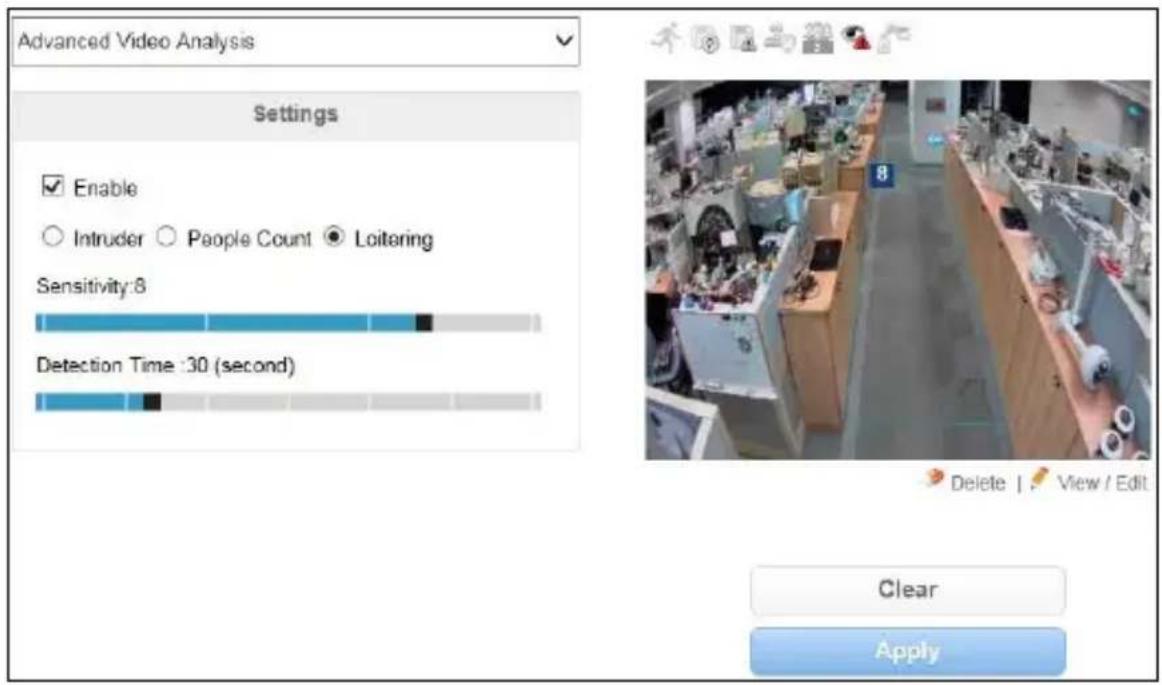
text_image
Advanced Video Analysis Settings Enable Intruder ○ People Count ● Loitering Sensitivity:8 Detection Time:30 (second) Clear ApplyFigure 4-19
- Select Enable.
- Select Loitering.
- To define a detection region:
A. Use the slider to set a desired sensitivity level for the detection region you want to define in step 4B. The sensitivity levels range from 1 to 10, with 8 as default. The higher the level, the more sensitive the camera is to motion.
B. On the live view, draw a detection area. To draw an irregular shape, drag one or more of the red dots that outline the box until the line is in the shape that you want. See Figure 4-13.
C. Click Fix to confirm your setting.
D. To create several areas with different sensitivities, repeat steps 3A and 3B.
E. To clear any defined area, click Delete under the image, and click the X icon to remove it. Click again to return to the setting.
- Use the Detection Time slider to set the time length required for the alarm to be triggered if the system detects any motion within the defined area. The default setting is 30 seconds.
- To activate loitering settings at specific time periods each day, create a schedule. For details, see Step 6 in 4.2.1 Motion Detection.
- Click Apply to save all the settings.
Note: To allow the loitering detection settings to take effect, please wait for 2 minutes upon clicking the Apply button.
In GV-VMS, when the event is detected on the camera, you will see the log "Loitering" as illustrated below.
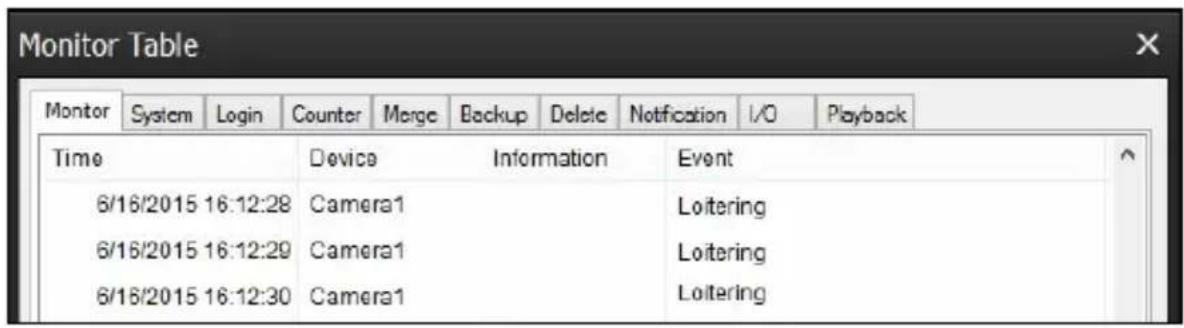
text_image
Monitor Table Monitor System hemg Login Counter Merge Backup Delete Notification I/O Playback Time Device Information Event 6/16/2015 16:12:28 Camera1 Loitering 6/16/2015 16:12:29 Camera1 Loitering 6/16/2015 16:12:30 Camera1 LoiteringFor details on how to connect to GV-VMS, see 7.2 Setting up IP Cameras on GV-VMS.
IMPORTANT: It is required to enable the “Video Analysis on Camera” function on GV-VMS in advance. See Important note on page 78.
4.2.3 Unattended Object / Missing Object Detection
When any unattended objects or missing objects are detected within the camera view, the event will be recorded to the connected surveillance system GV-VMS for later retrieval.
- From the Video Analysis drop-down list, select Unattended Object / Missing Object Detection. This page appears.
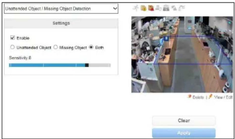
text_image
Unattended Object / Missing Object Detection Settings Enable Unattended Object Missing Object Both Sensitivity: 8 Delete View Edit Clear ApplyFigure 4-20
- Select Enable.
- Select one of the following tasks.
■ Unattended Object: An object left unattended.
■ Missing Object: The removal of an object from the defined region.
■ Both
-
Use the Sensitivity slider to set a desired sensitivity level for the detection region you want to define in step 5. The sensitivity levels range from 1 to 10, with 8 as default. The higher the level, the more sensitive the camera is to motion.
-
On the live view, draw the detection area. To draw an irregular shape, drag one or more of the red dots that outline the box until the line is in the shape that you want. See Figure 4-13.
- Click Fix to confirm your setting.
- To draw a new detection area, repeat steps 4 to 5. You can draw up to 4 areas.
- To clear any defined area, click Delete under the image, and click the X icon to remove it. Click again to return to the setting.
- To activate unattended object / missing object detection settings at specific time periods each day, create a schedule. For details, see Step 6 in 4.2.1 Motion Detection.
- Click Apply to save all the settings.
Note: To allow the unattended object / missing object detection settings to take effect, please wait for 2 minutes upon clicking the Apply button.
In GV-VMS, when the event is detected on the camera, you will see the log "Advanced Unattended Object Detection" or "Advanced Missing Object Detection" as illustrated below.
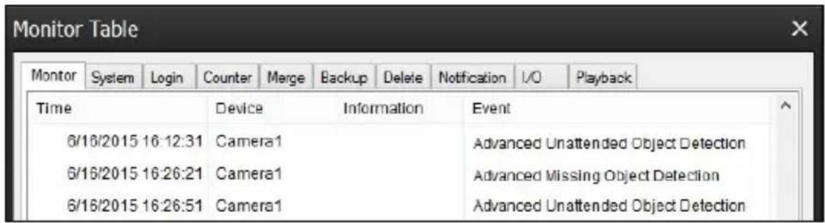
text_image
Monitor Table Monitor System hem Login Counter Merge Backup Delete Notification I/O Playback Time Device Information Event 6/16/2015 16:12:31 Camera1 Advanced Unattended Object Detection 6/16/2015 16:26:21 Camera1 Advanced Missing Object Detection 6/16/2015 16:26:51 Camera1 Advanced Unattended Object DetectionFor details on how to connect to GV-VMS, see 7.2 Setting up IP Cameras on GV-VMS.
IMPORTANT: It is required to enable the “Video Analysis on Camera” function on GV-VMS in advance. See Important note on page 78.
4.2.4 Tampering Alarm
The Tampering Alarm is used to detect when a camera is being physically tampered. When the camera is moved, covered up, or out of focus, the email alert can be sent, and the connected surveillance system GV-VMS, GV-Center V2 and GV-Vital Sign Monitor will record the event.
- From the Video Analysis drop-down list, select Tampering Alarm. This page appears.
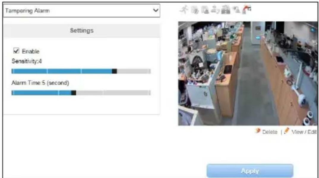
text_image
Tampering Alarm Settings Enable Sensitivity:4 Alarm Time: 5 (second) ApplyFigure 4-21
- Select Enable.
- Use the Sensitivity slider to set a desired detection sensitivity level. The sensitivity levels range from 1 to 10, with 8 as default. The higher the level, the more sensitive the camera is to motion.
- Use the Alarm Time slider to set the time length allowed for scene changes before an alarm event is generated.
- To activate tampering alarm settings at specific time periods each day, create a schedule. For details, see Step 6 in 4.2.1 Motion Detection.
-
Click Apply to start detection.
-
To trigger the e-mail alert when tampering alarm is detected, configure e-mail server and select Motion Detection alarm. See 4.4.1 E-Mail
- To notify GV-Center V2, GV-Vital Sign Monitor and GV-VMS when tampering alarm is detected, enable the connection to these systems. See 4.4.3 Center V2, 4.4.4 Vital Sign Monitor and 7.2 Setting up IP Cameras on GV-VMS.
In GV-VMS, when the event is detected on the camera, you will see the log "Advanced Scene Change Detection" as illustrated below.
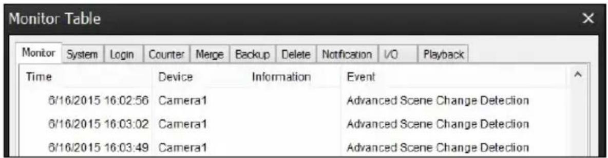
text_image
Monitor Table Monitor System hem Login Counter Merge Backup Delete Notification I/O Playback Time Device Information Event 6/16/2015 16:02:56 Camera1 Advanced Scene Change Detection 6/16/2015 16:03:02 Camera1 Advanced Scene Change Detection 6/16/2015 16:03:49 Camera1 Advanced Scene Change DetectionIMPORTANT: It is required to enable the "Video Analysis on Camera" function on GV-VMS in advance. See Important note on page 78.
4.3 I/O Settings
Note the I/O settings are only available for Box Camera, Bullet Camera, Ultra Bullet Camera, PTZ Camera, PT Camera, Vandal Proof IP Dome, and Fixed IP Dome.
After installing the I/O device, you need to enable the I/O settings on the camera. For how to install the I/O device on the camera, see the following reference sections in the corresponding Hardware Manual:
| GV-IPCAM Reference section | |
| Box Camera I/O Terminal Block | |
| Bullet Camera | Connecting the CameraConnecting the Camera |
| PTZ Camera I/O Terminal Block | |
| PT Camera I/O Terminal Block | |
| Vandal Proof IP Dome Connecting the Camera | |
| Fixed IP Dome I/O Terminal Block | |
4.3.1 Input Settings
To activate the sensor input, select Enable.
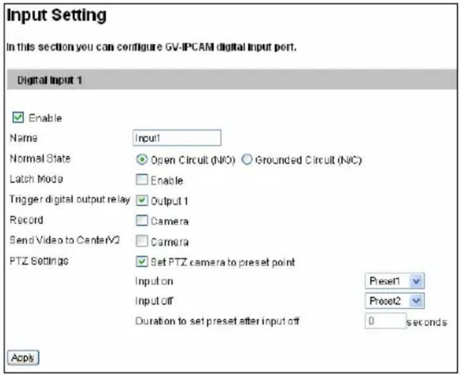
text_image
Input Setting In this section you can configure GV-IPCAM digital input port. Digital Input 1 Enable Name Input1 Normal State Open Circuit (N/O) Grounded Circuit (N/C) Latch Mode Enable Trigger digital output relay Output 1 Record Camera Send Video to Center/V2 Camera PTZ Settings Set PTZ camera to preset point Input on Preset1 Input off Preset2 Duration to set preset after input off 0 seconds ApplyFigure 4-22
■ Normal State: You can set the input state to trigger actions by selecting Open Circuit (N/O) or Grounded Circuit (N/C).
■ Latch Mode: Enable this option to have a momentary output alarm.
■ Trigger digital output relay: When this option is enabled, the output will be triggered once the input is activated.
■ Record: Enable this option to start recording when the input is triggered.
■ Send Video to Center V2: Enable this option to send the images to Center V2 when the input is triggered.
■ PTZ Settings: Note this function is only available for PTZ Camera and PT Camera.
- Input On: Select a preset point to which the camera turns when an input is triggered.
- Input Off: Select a preset point to which the camera returns when the input triggering is off.
- Duration to set preset after input off: Specify the duration that the camera stays at the Input On point before returning to the Input Off point.
Note:
- The GV-IP Cameras support dry-contact input device.
- The functions “triggering the output”, “starting the recording when the input is triggered” and “sending video to Center V2” only work after you start Input monitoring manually or by schedule. To configure the input monitoring, see 4.5 Monitoring.
4.3.2 Output Settings
Select Enable to start the output device. Choose the output signal that mostly suits the device you are using: N/O (Open Circuit), N/C (Grounded Circuit), N/O Toggle, N/C Toggle, N/O Pulse or N/C Pulse. For Toggle output type, the output continues to be triggered until a new input trigger ends the output. For Pulse output type, the output is triggered for the amount of time you specify in the Trigger Pulse Mode for x Seconds field.
[Alarm Settings] You can choose to automatically trigger the digital output under these conditions: tampering alarm (not available for PTZ Camera), disk write error (Rec Error) and full memory card (HD Full).
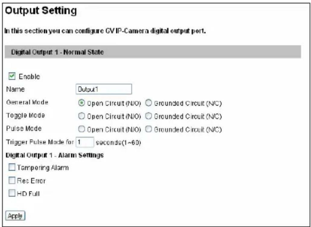
text_image
Output Setting In this section you can configure GV IP-Camera digital output port. Digital Output 1 - Normal State Enable Name Output1 General Mode Open Circuit (N/O) Grounded Circuit (N/C) Toggle Mode Open Circuit (N/O) Grounded Circuit (N/C) Pulse Mode Open Circuit (N/O) Grounded Circuit (N/C) Trigger Pulse Mode for 1 seconds(1~60) Digital Output 1 - Alarm Settings Tampering Alarm Rec Error HD Full ApplyFigure 4-23
4.3.3 PTZ Settings
Note this function is only available in PTZ Camera and PT Camera.
You can change the image settings, configure sequences, and access settings including autopan speed, motor reset, digital zoom and system default loading. For details, see Accessing the VISCA OSD Configuration in the Hardware Manual.
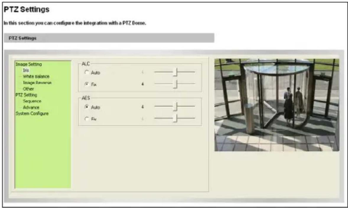
text_image
PTZ Settings In this section you can configure the integration with a PTZ Dome. PTZ Settings Image Setting Iris White balance Image Reversus Other PTZ Setting Sequence Advance System Configure ALC Auto 4 Fix 4 AES Auto 4 Fix 4Figure 4-24
4.4 Events and Alerts
For the events of motion detection or I/O trigger, the Administrator can set up two trigger actions:
- Send a captured still image by E-mail or FTP.
- Notify Center Monitoring Station, Center V2 or Vital Sign Monitor, by video or text alerts.
To have the above trigger actions, you must set the following functions in advance:
● Motion Detection (See 4.1.2 Motion Detection)
S7
- Input Setting (See 4.3.1 Input Setting)
- For e-mail and FTP alerts, it is required to start monitoring (See 4.5 Monitoring).
4.4.1 E-mail
After a trigger event, the camera can send the e-mail to a remote user containing a captured still image.
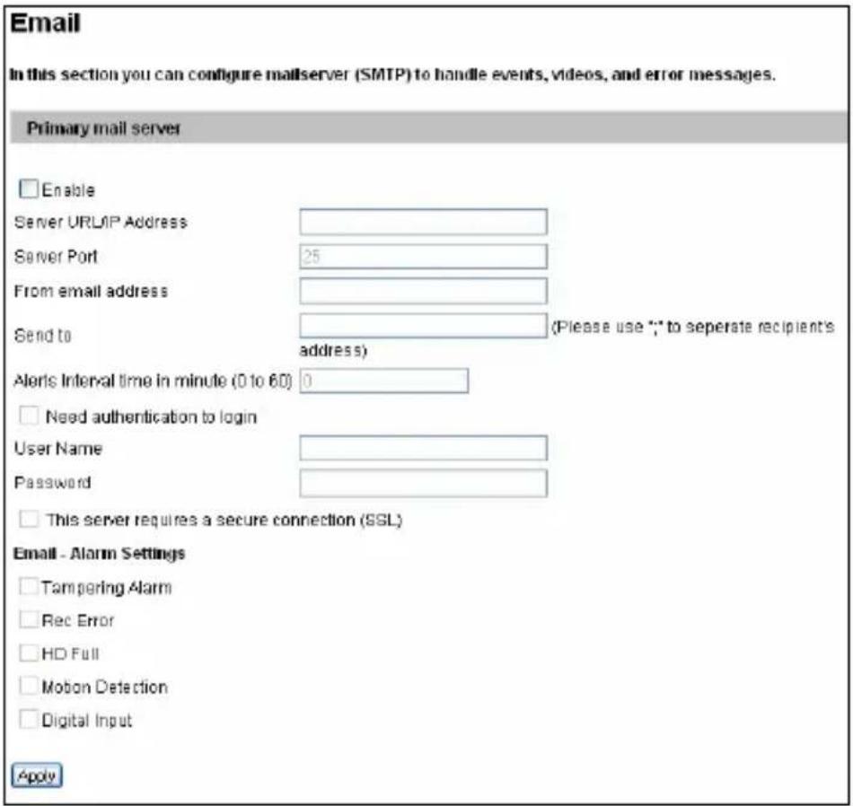
text_image
Email In this section you can configure mailserver (SMTP) to handle events, videos, and error messages. Primary mail server Enable Server URL/IP Address Server Port 25 From email address Send to (Please use ** to separate recipient's address) Alerts Interval time in minute (0 to 60) 0 Need authentication to login User Name Password This server requires a secure connection (SSL) Email - Alarm Settings Tampering Alarm Rec Error HD Full Mobon Detection Digital Input ApplyFigure 4-25
[Enable] Select to enable the e-mail function.
■ Sever URL/IP Address: Type the URL address or IP address of the SMTP Server.
■ Server Port: Modify the port number of the SMTP Server. Or keep the default value 25.
■ From email address: Type the sender's e-mail address.
■ Send to: Type the e-mail address(s) you want to send alerts to.
- Alerts Interval Time: Specify the interval between e-mail alerts. The interval is between 0 and 60 minutes. The option is useful for the frequent event occurrence, by which any event triggers during the interval period will be ignored.
[Need authentication to login] If the SMTP Server needs authentication, enable this option and type a valid username and password to log in the SMTP server.
[E-Mail Alarm Settings] You can choose to automatically send an e-mail alert under these conditions: tampering alarm, disk write error (Rec Error), full memory card (HD Full), motion detection and input trigger. Note that the alert condition is only supported if the corresponding function is supported in that camera model.
IMPORTANT: To send e-mail alerts upon motions, be sure to set up detection area on the Motion Detection's page.
For the related settings to send e-mail alerts, see 4.1.2 Motion Detection, 4.3.1 Input Setting and 4.5 Monitoring.
Note: For GV-BX12201, the maximum resolution of the captured still image sent by E-mail alert is 1 MP.
4.4.2 FTP
You can also send the captured images to a remote FTP server as alerts.
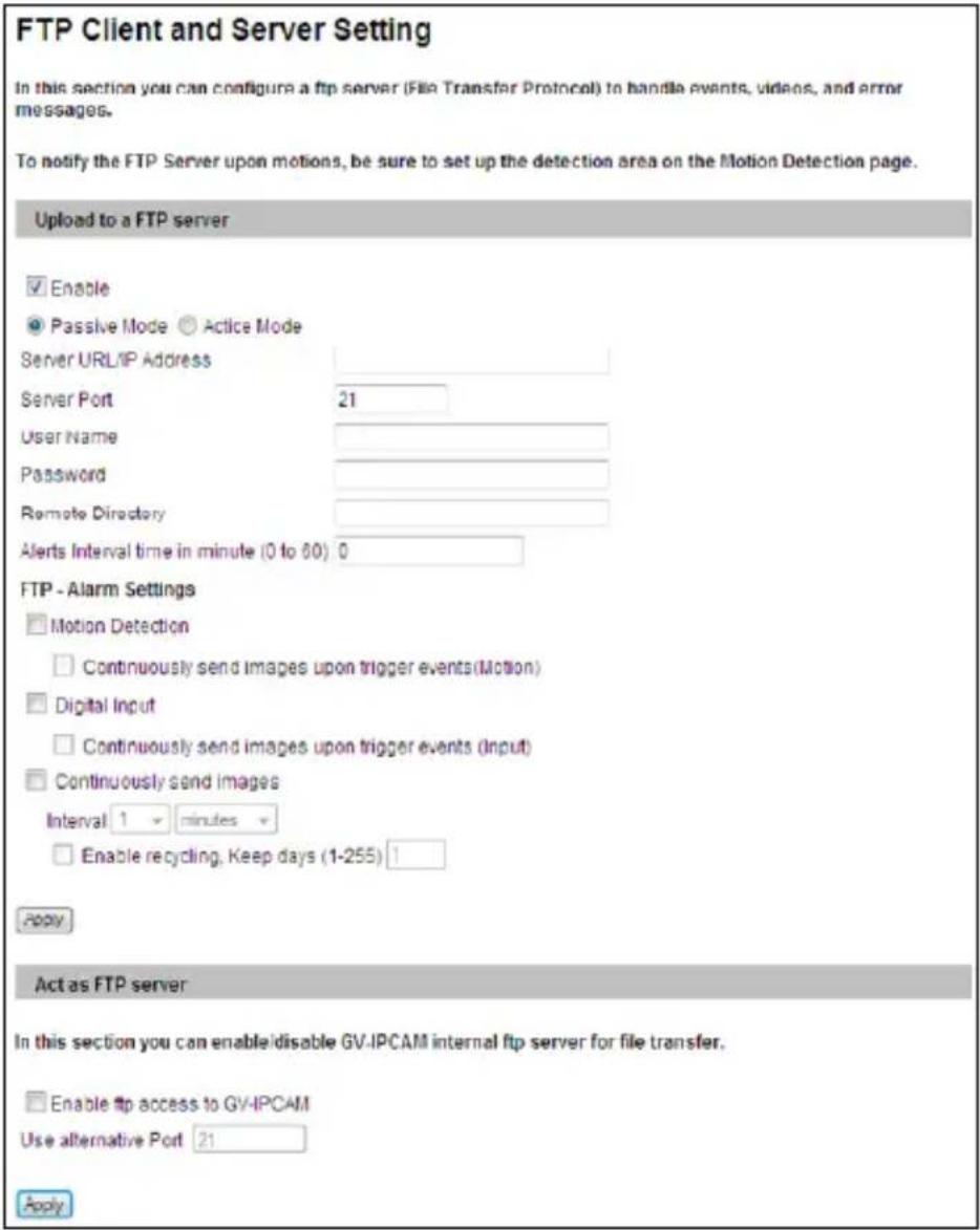
text_image
FTP Client and Server Setting In this section you can configure a ftp server (File Transfer Protocol) to handle events, videos, and error messages. To notify the FTP Server upon motions, be sure to set up the detection area on the Motion Detection page. Upload to a FTP server Enable Passive Mode Active Mode Server URL/IP Address Server Port 21 User Name Password Remote Directory Alerts Interval time in minute (0 to 60) 0 FTP - Alarm Settings Motion Detection Continuously send images upon trigger events(Motion) Digital Input Continuously send images upon trigger events (Input) Continuously send images Interval 1 minutes Enable recycling, Keep days (1-255) 1 Apply Act as FTP server In this section you can enable/disable GV-IPCAM internal ftp server for file transfer. Enable ftp access to GV-IPCAM Use alternative Port 21 ApplyFigure 4-26
[Upload to an FTP Server]
■ Enable: Select to enable the FTP function and then select Active Mode or Passive Mode, depending on the setting of your FTP server.
■ Server URL/IP Address: Type the URL address or IP address of the FTP Server.
■ Server Port: Type the port number of the FTP Server. Or keep the default value 21.
■ User Name: Type a valid username to log into the FTP Server.
■ Password: Type a valid password to log into the FTP Server.
■ Remote Directory: Type the name of the storage folder on the FTP Server.
- Alerts Interval time in minute: Specify the interval between FTP alerts. The interval can be between 0 and 60 minutes. The option is useful for the frequent event occurrence by which any event triggers during the interval period will be ignored.
[Alarm Settings]
■ Motion Detection: When a motion is detected on the camera, a still image will be sent to the FTP Server.
Continuously send images upon trigger events (motion): A sequence of snapshots is uploaded to the FTP Server when a motion is detected. This stops as soon as no motion is detected.
■ Digital Input: Note this function is only supported by cameras with I/O function. Once the input is triggered, a still image will be sent to the FTP Server.
- Continuously send images upon trigger events (input): A sequence of snapshots is uploaded to the FTP Server when the input is triggered.
■ Continuously send images: Sends images to the FTP server at the specified interval.
- Interval: Use the drop-down list to specify how frequent the images are sent to the FTP server.
- Enable Recycling: Select this option to recycle the FTP storage at the specified Keep Day.
- Keep Days: Specify how frequent the images saved at the FTP server are recycled. By default, the Keep Day is set to 1.
IMPORTANT: To send FTP alerts upon motions, be sure to set up detection area on the Motion Detection's page.
[Act as FTP Server] Note this function is not available for Target Series.
■ Enable FTP access to the GV-IP Cam: The camera acts as an FTP server, enabling users to download AVI files.
■ Use alternative port: The default port is set to 21.
To access the internal FTP server through a web browser, enter the IP address or the domain name of the camera in your browser like this: ftp://192.168.0.10
When you are prompted for Username and Password, enter the default value username ftpuser and password 123456. Then you should find the AVI files recorded after trigger events.
To change login information of the internal FTP server, see 4.9.3 User Account. For related settings to send FTP alerts, see 4.1.2 Motion Detection, 4.3.1 Input Settings, and 4.5 Monitoring.
Note: For GV-BX12201, the maximum resolution of the captured still image sent by FTP alert is 1 MP.
4.4.3 Center V2
After a motion or an I/O triggered event, the central monitoring station Center V2 can be notified by live videos and text alerts. For the live monitoring through Center V2, you must already have a subscriber account on Center V2. A camera can connect to up to 2 Center V2 stations simultaneously.
IMPORTANT: To notify Center V2 server upon motions, be sure to set up detection areas on the Motion Detection's page,
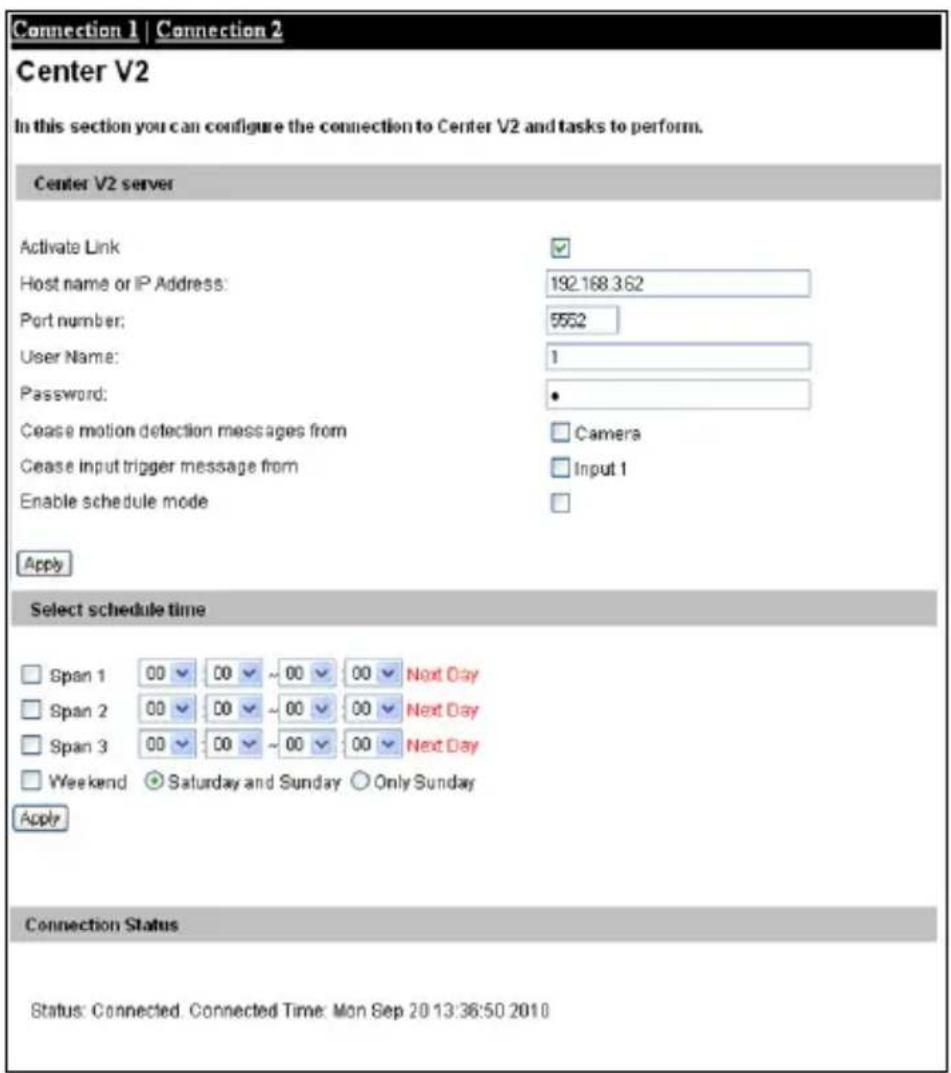
text_image
Connection 1 | Connection 2 Center V2 In this section you can configure the connection to Center V2 and tasks to perform. Center V2 server Activate Link Host name or IP Address: 192.168.362 Port number: 5552 User Name: 1 Password: * Cease motion detection messages from Camera Cease input trigger message from Input 1 Enable schedule mode Apply Select schedule time Span 1 00 00 ~ 00 00 Next Day Span 2 00 00 ~ 00 00 Next Day Span 3 00 00 ~ 00 00 Next Day Weekend Saturday and Sunday Only Sunday Apply Connection Status Status: Connected. Connected Time: Mon Sep 20 13:36:50 2010Figure 4-27
To enable the Center V2 connection:
- Activate Link: Enable the monitoring through Center V2.
- Host Name or IP Address: Type the host name or IP address of Center V2.
- Port Number: match the port to the Port 2 value on Center V2 or keep the default value 5551.
- User Name: type a valid username to log into Center V2.
- Password: Type a valid password to log into Center V2
- Click Apply. The Connection Status should display "Connected" and connected time.
- To establish connection to the second Center V2 server, click the Connection 2 tab and repeat the above steps for setup.
You can also find the following options on this Center V2 setting page:
■ Cease motion detection messages from: Stops notifying Center V2 of motion-triggered events.
■ Cease input trigger messages from: Note this function is only supported by cameras with I/O function. Stops notifying Center V2 of input-triggered events.
■ Enable schedule mode: Starts the monitoring through Center V2 based on the schedule you set in the Select Schedule Time section. Refer to 4.6 Recording Schedule for the same settings.
For related settings to activate the monitoring through Center V2, see 4.1.2 Motion Detection, 4.3.1 Input Setting and 8.1 Center V2.
4.4.4 Vital Sign Monitor
After a motion or an I/O triggered event, the central monitoring station Vital Sign Monitor can get notified by text alerts. For the monitoring through Vital Sign Monitor, you must already have a subscriber account on Vital Sign Monitor. A camera can connect up to 2 Vital Sign Monitors simultaneously.
IMPORTANT: To notify GV-Vital Sign Monitor server upon motions, be sure to set up detection areas on the Motion Detection's page,
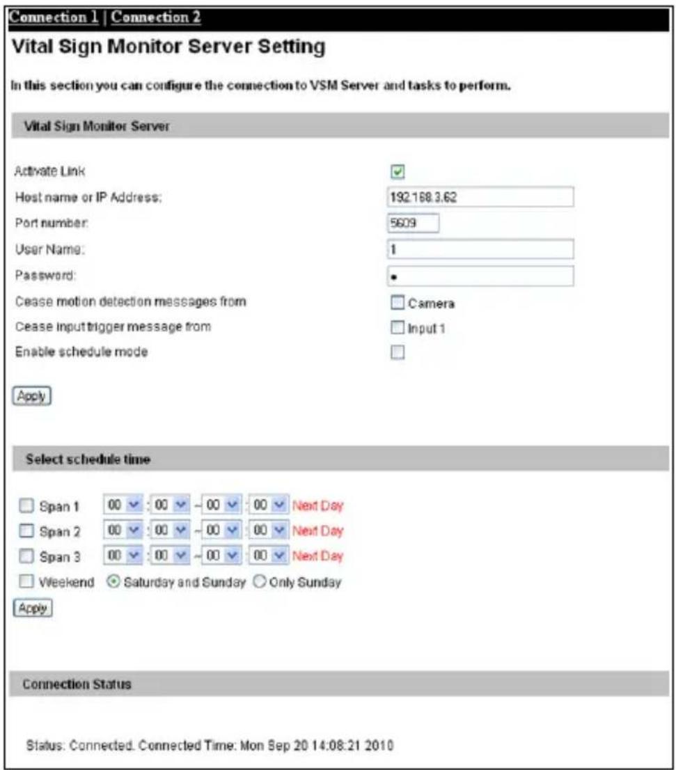
text_image
Connection 1 | Connection 2 Vital Sign Monitor Server Setting In this section you can configure the connection to VSM Server and tasks to perform. Vital Sign Monitor Server Activate Link Host name or IP Address: 192.168.3.62 Port number: 5609 User Name: 1 Password: * Cease motion detection messages from Camera Cease input trigger message from Input 1 Enable schedule mode Apply Select schedule time Span 1 00 00 - 00 00 Next Day Span 2 00 00 - 00 00 Next Day Span 3 00 00 - 00 00 Next Day Weekend Saturday and Sunday Only Sunday Apply Connection Status Status: Connected. Connected Time: Mon Sep 20 14:08:21 2010Figure 4-28
To enable the Vital Sign Monitor connection:
- Activate Link: Enable the monitoring through Vital Sign Monitor.
- Host Name or IP Address: Type the host name or IP address of Vital Sign Monitor.
- Port Number: Match the port to the Port 2 value on Vital Sign Monitor. Or keep the default value 5609.
- User Name: Type a valid username to log into Vital Sign Monitor.
- Password: Type a valid password to log into Vital Sign Monitor.
- Click Apply. The Connection Status should display "Connected" and connected time.
- To establish connection to the second Vital Sign Monitor, click the Connection 2 tab and repeat the above steps for setup.
These options you can also find on this Vital Sign Monitor setting page:
■ Cease motion detection messages from: Stops notifying Vital Sign Monitor of motion-triggered events.
■ Cease input trigger messages from: Note this function is only supported by cameras with I/O function. Stops notifying Vital Sign Monitor of input-triggered events.
■ Enable schedule mode: Starts the monitoring through Vital Sign Monitor based on the schedule you set in the Select Schedule Time section. Refer to 4.6 Recording Schedule for the same settings.
For related settings to activate the monitoring through Vital Sign Monitor, see 4.1.2 Motion Detection and 4.3.1 Input Settings, and 8.2 Vital Sign Monitor.
4.4.5 Backup Center
For the supported version of different models, see Appendix C. Note that Backup Center is not supported for Target Series and GV-BX2600.
The connection to the GV-Backup Center allows you to back up another copy of recordings and system log to the GV-Backup Center on an offsite location while the camera is saving these data to the memory card. The GV-Backup Center provides a PC-based storage and backup solution. For details on the GV-Backup Center, see GV-Backup Center User's Manual.
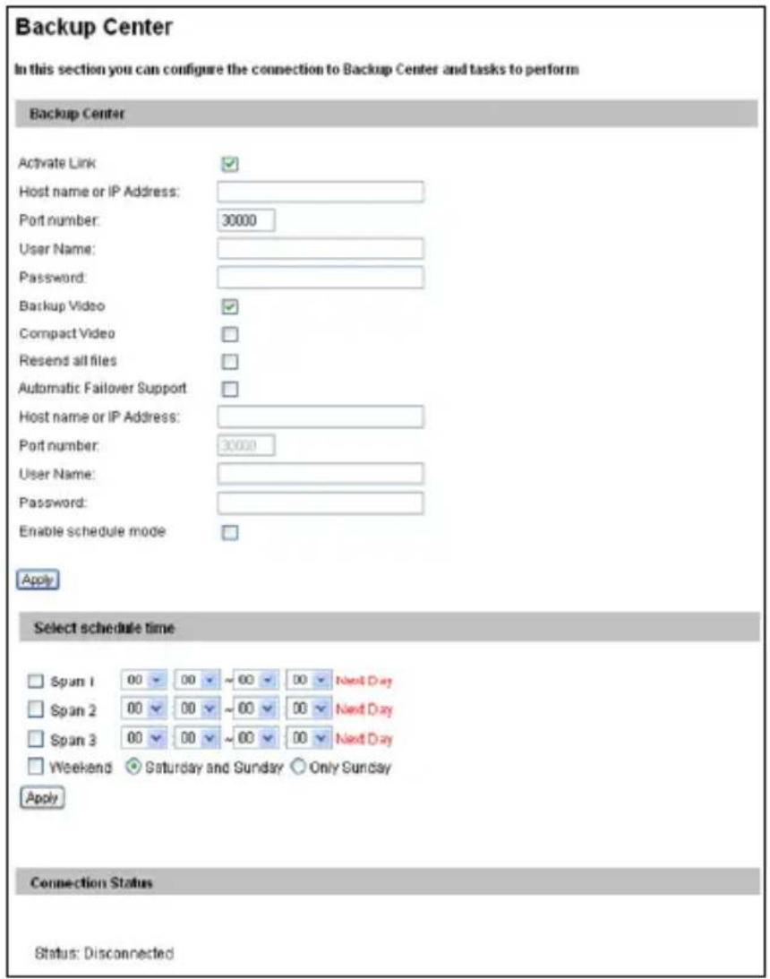
text_image
Backup Center In this section you can configure the connection to Backup Center and tasks to perform Backup Center Activate Link Host name or IP Address: Port number: 30000 User Name: Password: Backup Video Compact Video Resend all files Automatic Failover Support Host name or IP Address: Port number: 30000 User Name: Password: Enable schedule mode Apply Select schedule time Span 1 00 00 ~ 00 00 Next Day Span 2 00 00 ~ 00 00 Next Day Span 3 00 00 ~ 00 00 Next Day Weekend Saturday and Sunday Only Sunday Apply Connection Status Status: DisconnectedFigure 4-29
To enable connection to GV-Backup Center:
- Activate Link: Enable the connection to the GV-Backup Center.
- Host Name or IP Address: Type the host name or IP address of the GV-Backup Center.
- Port Number: Match the communication port on the GV-Backup Center or keep the default value 30000.
- User Name: Type a valid user name to log into the GV-Backup Center.
- Password: Type a valid password to log into the GV-Backup Center.
- Backup Video: Select the streams to back up their recordings to the GV-Backup Center.
- Compact Video: Select the streams to only back up their Key Frames to the GV-Backup Center, instead of full recordings. This option is useful to save the backup time.
- Resend all files: Select this option to send all the recorded files that have received by the Backup Center again.
- Enable Schedule Mode: Enable the GV-Backup Center connection on the schedule you set in the Select Schedule Time section. Refer to 4.6 Recording Schedule for the same settings.
- Click Apply. The Connection Status should display "Connected" and connected time.
If you have a failover GV-Backup Center server which provides uninterrupted backup services in case the first GV-Backup Center failed, configure the failover GV-Backup Center as below.
-
Automatic Failover Support: Enable the automatic connection to the failover GV-Backup Center once the connection between camera and the first GV-Backup Center is interrupted.
-
Host Name or IP Address: Type the host name or IP address of the failover GV-Backup Center.
- Port Number: Match the communication port on the failover GV-Backup Center or keep the default value 30000.
- User Name: Type a valid user name to log into the failover GV-Backup Center.
- Password: Type a valid password to log into the failover GV-Backup Center.
- Click Apply.
4.4.6 Video Gateway / Recording Server
For the supported version of different models, see Appendix C.
The GV-Video Gateway / GV-Recording Server is a video streaming server designed for large-scale video surveillance deployments. The GV-Video Gateway / GV-Recording Server (with recording capability) can receive up to 128 channels from various IP video devices, and distribute up to 300 channels to its clients. With the GV-Video Gateway / GV-Recording Server, the desired frame rate can be ensured while the CPU loading and bandwidth usage of the IP video devices are significantly reduced.
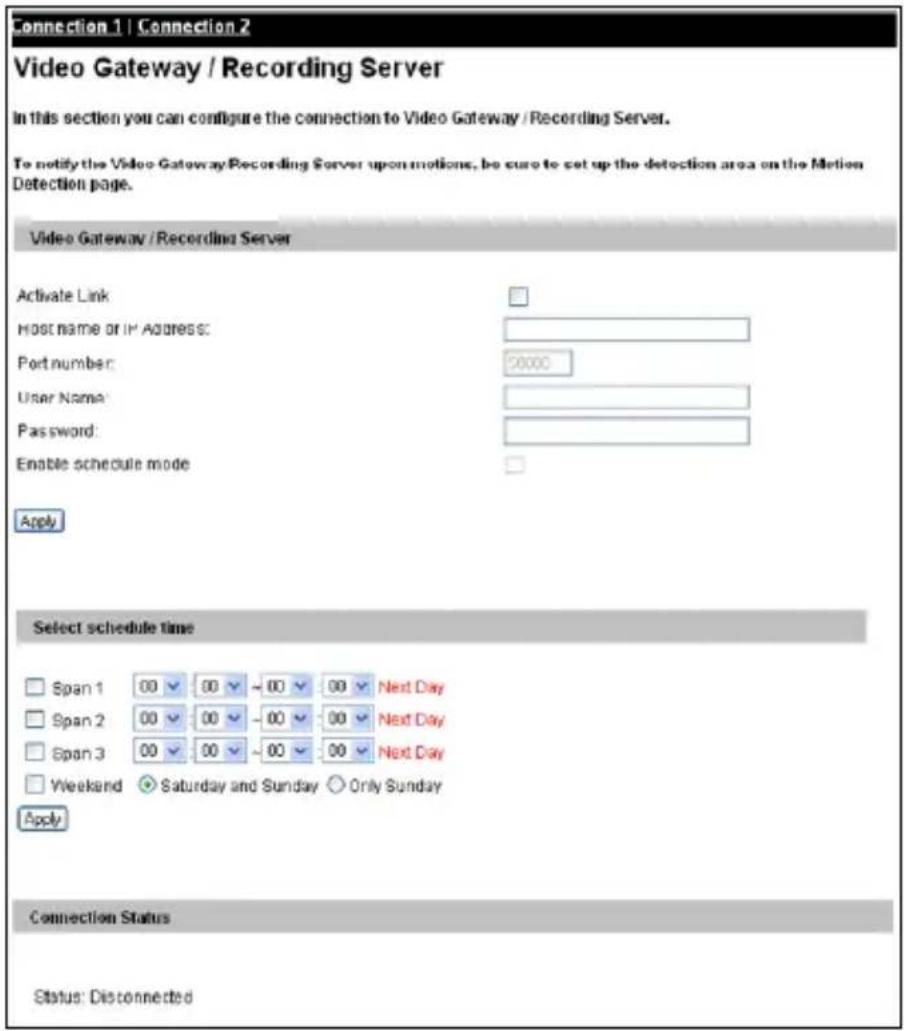
text_image
Connection 1 | Connection 2 Video Gateway / Recording Server In this section you can configure the connection to Video Gateway / Recording Server. To notify the Video Gateway/Recording Server upon motions, be sure to set up the detection area on the Motion Detection page. Video Gateway /Recording Server Activate Link Host name or IP Address: Port number: 0000 User Name: Password: Enable schedule mode Apply Select schedule time Span 1 00 00 ~ 00 00 Next Day Span 2 00 00 ~ 00 00 Next Day Span 3 00 00 ~ 00 00 Next Day Weekend Saturday and Sunday Only Sunday Apply Connection Status Status: DisconnectedFigure 4-30
The supported GV-IPCAM can connect up to two GV-Video Gateway / GV-Recording Server. To send the video images to the GV-Video Gateway or GV-Recording Server, follow the steps below.
- Activate Link: Enable the connection to the GV-Video Gateway / GV-Recording Server.
- Host Name or IP Address: Type the host name or IP address of the GV-Video Gateway / GV-Recording Server.
- Port Number: Match the communication port on the GV-Video Gateway / GV-Recording Server or keep the default value 50000.
- User Name: Type a valid user name to log into the GV-Video Gateway / GV-Recording Server.
- Password: Type a valid password to log into the GV-Video Gateway / GV-Recording Server.
- Enable Schedule mode: Enable the GV-Video Gateway / GV-Recording Server on the schedule you set in the Select Schedule Time section. Refer to 4.6 Recording Schedule for the same settings.
- Click Apply. The Connection Status should display "Connected" and the connected time.
- To establish connection to the second GV-Video Gateway / GV-Recording Server, click the Connection 2 tab and repeat the above steps for setup.
4.4.7 ViewLog Server
Note that ViewLog Server is not supported for Target Series.
The ViewLog Server is designed for remote playback function. This server allows you to remotely access the recorded files saved at the GV-IPCAM and play back video with the ViewLog player.
This function is enabled by default using port 5552. Keep the default setting and only modify it when necessary. For details on the remote playback, see 5.2.2 Playback over Network.
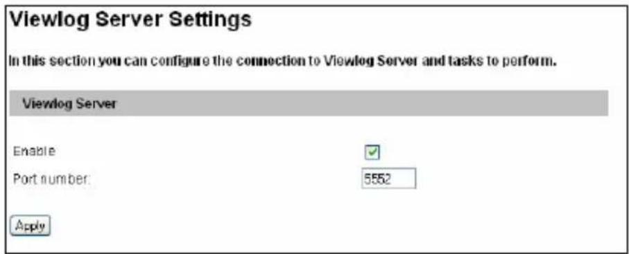
text_image
Viewlog Server Settings In this section you can configure the connection to Viewlog Server and tasks to perform. Viewlog Server Enable Port number: 5552 ApplyFigure 4-31
4.4.8 RTSP/ONVIF
The RTSP enables video and audio streaming to your 3G-enabled mobile phone. The RTSP streaming is enabled by default.
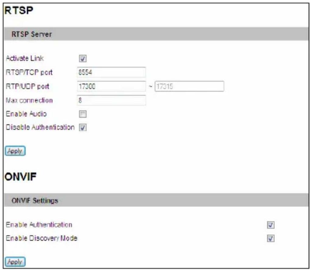
text_image
RTSP RTSP Server Activate Link ✓ RTSP/TCP port 8554 RTP/UDP port 17300 ~ 17315 Max connection 8 Enable Audio Disable Authentication ✓ Apply ONVIF ONVIF Settings Enable Authentication ✓ Enable Discovery Mode ✓ ApplyFigure 4-32
[RTSP]
■ Activate Link: Enable the RTSP service.
■ RTSP/TCP Port: Keep the default value 8554, or modify it if necessary.
■ RTP/UDP Port: Keep the default range from 17300 to 17319, or modify it if necessary. The number of ports for use is limited to 20.
■ Max Connection: Set the maximum number of RTSP and 3GPP connections to the camera. The maximum value is 8.
■ Enable Audio: Note this function is not available for Target Bullet Camera, Target Mini Fixed Rugged Dome and Ultra Bullet Camera. Turns audio streaming on or off. For the supported firmware versions, see Appendix C.
■ Disable Authentication: By default, when accessing live view through RTSP command, the ID and password of the camera are required. Select this option to disable the authentication prompt. For the supported firmware versions, see Appendix D.
For details on remote monitoring with mobile phones, see Mobile Phone Connection, Chapter 26. For RTSP command, see Appendix D.
[ONVIF]
■ Enable Authentication: The ID and password of the camera are required to access the camera by a third-party DVR through ONVIF. This function is enabled by default.
■ Enable Discovery Mode: Allows the third-party DVR to browse this camera. This function is enabled by default.
4.4.9 Speaker
Note this function is only available for Advanced Cube Camera.
The Advanced Cube camera is equipped with an alarm. With the Speaker settings, your camera can sound the speaker when the camera is being tampered or when motions are detected. This function is disabled by default.
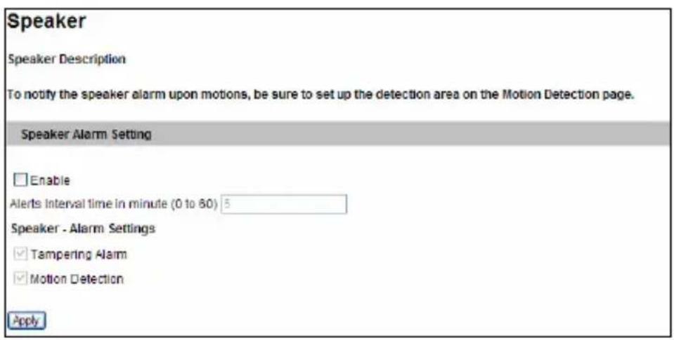
text_image
Speaker Speaker Description To notify the speaker alarm upon motions, be sure to set up the detection area on the Motion Detection page. Speaker Alarm Setting Enable Alerts Interval time in minute (0 to 80) 5 Speaker - Alarm Settings Tampering Alarm Motion Detection ApplyFigure 4-33
- Select Enable.
- Type the duration time in the Alerts Interval time field. The default value is 5 (minutes). When a motion is detected, the alarm will be on for the specified amount of time.
- Select Tampering Alarm and/or Motion Detection under Alarm Settings.
To sound the alarm upon motion events, make sure you have enabled motion detection. For details, see 4.1.2 Motion Detection.
4.5 Monitoring
You can start monitoring manually, by schedule or by input trigger.
Note:
- See Note for Connecting to GV-System / GV-VMS at the beginning of the manual.
- For GV-EBL2101, see 4.5.1 Monitoring Settings for GV-EBL2101 for corresponding page.
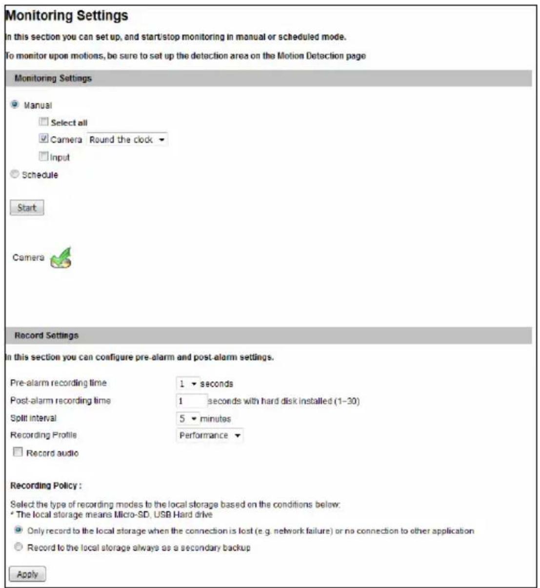
text_image
Monitoring Settings In this section you can set up, and start/stop monitoring in manual or scheduled mode. To monitor upon motions, be sure to set up the detection area on the Motion Detection page Monitoring Settings ● Manual Select all ✓ Camera Round the clock Input ○ Schedule Start Camera Record Settings In this section you can configure pre-alarm and post-alarm settings. Pre-alarm recording time 1 seconds Post-alarm recording time 1 seconds with hard disk installed (1-30) Split interval 5 minutes Recording Profile Performance □ Record audio Recording Policy : Select the type of recording modes to the local storage based on the conditions below: * The local storage means Micro-SD, USB Hard drive ● Only record to the local storage when the connection is lost (e.g. network failure) or no connection to other application ○ Record to the local storage always as a secondary backup ApplyFigure
4-34
[Manual] Manually activates motion detection and I/O monitoring. Select one of the following options and then click the Start button.
■ Select all: Manually starts both motion detection and I/O monitoring.
■ Camera: Manually starts recording. Select the desired recording mode for recording.
■ Input: Note this function is only supported by cameras with I/O function. Manually starts I/O monitoring. When the sensor input is triggered, its associated camera and output will be activated for recording and alerting. For this setting, see 4.3.1 Input Setting.
[Schedule] The system starts motion detection and I/O monitoring according to the schedule you have set. For schedule settings, see 4.6 Recording Schedule.
[Camera Status Icon]
![Geovision GV-BX1500-3V - [Camera Status Icon] - 1](/content/2026/05/785387/images/bbfab8557d84e08586be15e137784ea8ddb2d050479debe8b7421470740f6328.jpg)
: On standby
![Geovision GV-BX1500-3V - [Camera Status Icon] - 2](/content/2026/05/785387/images/0e51c40da7d2d1d9fce298a8916b8ecb71ba6e3ff89cdf20464c5e1caf2ea2bd.jpg)
: Enabled for motion detection and input trigger
![Geovision GV-BX1500-3V - [Camera Status Icon] - 3](/content/2026/05/785387/images/24822162f1b6bf8e21c5f5af85da4924fe0aaa5b6b629069ac3d1d7243e48152.jpg)
: Recording is on.
[Recording Settings] Note this function is only supported by GV-BX12201 firmware V1.02 or later and GV-IPCAM H.265. Configure recording settings for motion and I/O events, and the condition to record.
Pre-alarm recording time: Activates video recording before an event occurs. Set the recording time to 1 or 2 seconds. The recording is saved in the buffer of the camera.
■ Post-alarm recording time: Activates video recording onto the inserted memory card after an event occurs. Set the recording time from 1 to 30 seconds.
Split-interval: Sets the time length between each event file from 1 to 5 minutes.
- Recording Profile: This setting is only applicable for recording to the camera's memory card. Select Performance to maximize the lifespan of the memory card by restricting the frame rate to 30 fps and maximum bit rate to 4 Mbit. Select Quality to adopt your current settings. The default setting is Performance.
■ Record audio: Activates audio recording when an event occurs.
■ Recording Policy: By default, the camera will only record to the memory card when the camera is not streaming live view to other applications (e.g. GV-VMS) or Web browser. Alternatively, you can set the camera to always record to the memory card as a secondary backup.
Note: When the camera is recording to the memory card, it is recommended to connect no more than two connections to the camera using Web interface or other applications.
4.5.1 Monitoring Settings for GV-EBL2101
In the Monitoring Settings page for GV-EBL2101, click Start to activate e-mail and FTP alert functions. Be sure to complete related settings on the Motion Detection, email and FTP pages.
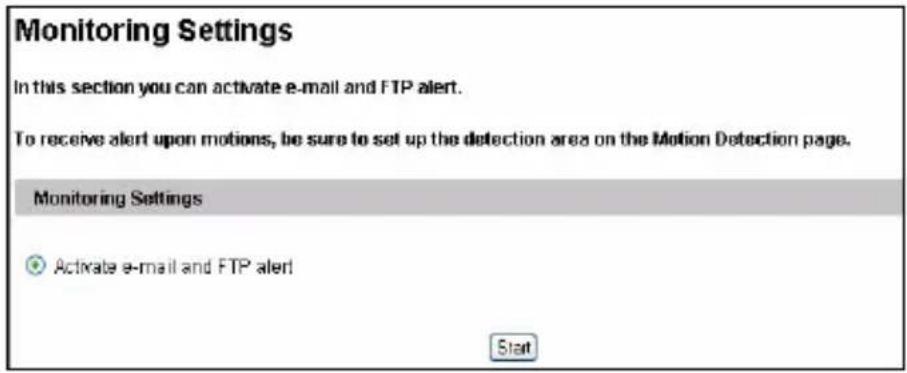
text_image
Monitoring Settings In this section you can activate e-mail and FTP alert. To receive alert upon motions, be sure to set up the detection area on the Motion Detection page. Monitoring Settings Activate e-mail and FTP alert Start4.6 Recording Schedule
Note this function is not available for GV-EBL2101.
The schedule is provided to activate recording and I/O monitoring on a specific time each day.
4.6.1 Recording Schedule Settings
You can set the schedule for recording.
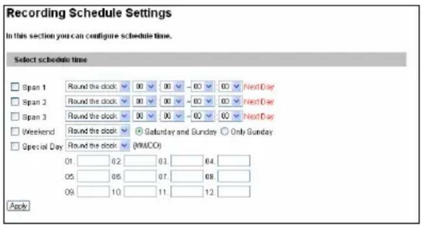
text_image
Recording Schedule Settings In this section you can configure schedule time. Select schedule time Span 1 Round the clock 00 00 -00 00 Next Day Span 2 Round the clock 00 00 ~00 00 Next Day Span 3 Round the clock 00 00 ~00 00 Next Day Weekend Round the clock Saturday and Sunday Only Sunday Special Day Round the clock (MMCO) 01. 02. 03. 04. 05. 06. 07. 08. 09. 10. 11. 12. ApplyFigure 4-36
■ Span 1- Span 3: Set a different recording mode for each time frame during the day. Each day can be divided into 3 time frames, represented by Span 1 to Span 3.
■ Weekend: Enable this option to start monitoring all day on the weekend and select the recording mode to be used. Define whether your weekend includes Saturday and Sunday or Only Sunday.
■ Special Day: Set the recording mode on a specified day.
4.6.2 I/O Monitoring Settings
Note this function is only supported by cameras with I/O function.
You can set the schedule for I/O monitoring to start.
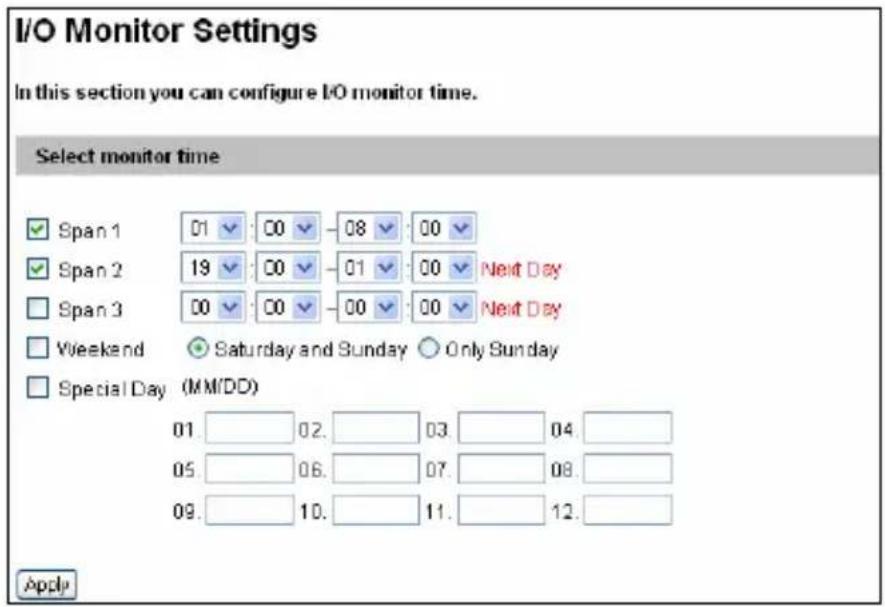
text_image
I/O Monitor Settings In this section you can configure I/O monitor time. Select monitor time Span 1 01 00 -08 00 Span 2 19 00 -01 00 Next Day Span 3 00 00 -00 00 Next Day Weekend ● Saturday and Sunday ○ Only Sunday Special Day (MM/DD) 01. 02. 03. 04. 05. 06. 07. 08. 09. 10. 11. 12. ApplyFigure 4-37
■ Span 1- Span 3: Set different time frames during the day to enable I/O monitoring. Each day can be divided into 3 time frames, represented by Span 1 to Span 3.
■ Weekend: Enable this option to start I/O monitoring all day on the weekend and define whether your weekend includes Saturday and Sunday or Only Sunday.
■ Special Day: Enable I/O monitoring on a specified day.
4.7 Remote ViewLog
Note this function is not available for Target Series.
With the Remote ViewLog player, you can play back the files recorded at the camera over TCP/IP network.
For the first-time user, you need to install the Remote ViewLog program from the Software DVD. To allow remote access to the camera, make sure the ViewLog Server function is enabled. See 4.4.7 ViewLog Server.
For details on connecting to the camera for playback, see 5.2.2 Playback over Network.
4.8 Network
The Network section includes some basic but important network configurations that enable the camera to be connected to a TCP/IP network.
4.8.1 LAN Configuration
According to your network environment, select among Static IP, DHCP and PPPoE.

text_image
LAN Configuration In this section you can configure GV-IPCAM to work inside of LAN. OptionalNetwork type Wired Ethernet Select this option to use wired 10/100Mbps ethernet Wireless Select this option to use Wireless LAN Configuration Dynamic IP address Select this option to obtain IP address from a DHCP server TestDHCP Static IP address Select this option to enter a Static IP address manually IP Address: 192.168.2.12 Subnet Mask: 255.255.252.0 RouterGateway: 192.168.0.1 Primary DNS: 168.95.121.1 Secondary DNS: 192.168.0.2 (Optional) PPPoE Select this option to establish a DSL connection Username: Password: WirelessSettings Dynamic IP address Select this option to obtain IP address from a DHCP server TestDHCP Static IP address Select this option to enter a Static IP address manually IP Address: 192.168.0.10 Subnet Mask: 255.255.255.0 RouterGateway: 192.168.0.1 Primary DNS: 192.168.0.1 Secondary DNS: 192.168.0.2 (Optional) ApplyFigure 4-38
[Optional Network Type]
Note the Wireless Settings are only available in GV-BX1200 Series / 1500 Series / 2400 Series / 2500 Series / 3400 Series / 5300 Series, GV-CAW120 / 220 and GV-MFD1501 Series / 2401 Series / 2501 Series / 3401 Series / 5301 Series. According to the network environment, select Wired Ethernet or Wireless. Before enabling the Wireless option, follow the steps in 2.1.3 Configuring the Wireless Connection to configure the wireless settings first.
[LAN Configuration]
■ Dynamic IP address: The network environment has a DHCP server which will automatically assign a dynamic IP address to the camera. Click the Test DHCP button to see the currently assigned IP address or look up the dynamic IP address using GV-IP Device Utility.
■ Static IP address: Assign a static IP or fixed IP to the camera and fill out the required settings. The default values are as below.
| Wired Ethernet Wireless | ||
| IP address 192.168.0.10 | 192.168.100.10 | |
| Subnet Mask 255.255.25 | 5.0 255.255.255.0 | |
| Router/Gateway | 192.168.0.1 | 192.168.0.1 |
| Primary DNS server 192. | 168.0.1 192.168.0.1 | |
| Secondary DNS server 1 | 92.168.0.2 192.168 | 0.2 |
■ PPPoE: The network environment is xDSL connection. Type the Username and Password provided by ISP to establish the connection. If you use the xDSL connection with dynamic IP addresses, first use the DDNS function to obtain a domain name linking to the camera's changing IP address.
For details on Dynamic DNS Server Settings, see 4.8.3 Advanced TCP/IP.
4.8.2 Wireless Client Mode
Note this function is only supported in GV-BX1200 Series / 1500 Series / 2400 Series / 2500 Series / 3400 Series / 5300, GV-CAW120 / 220 and GV-MFD1501 Series / 2401 Series / 2501 Series / 3401 Series / 5301 Series and when GV-WiFi Adapter is installed. Set up the client mode before enabling the wireless function.
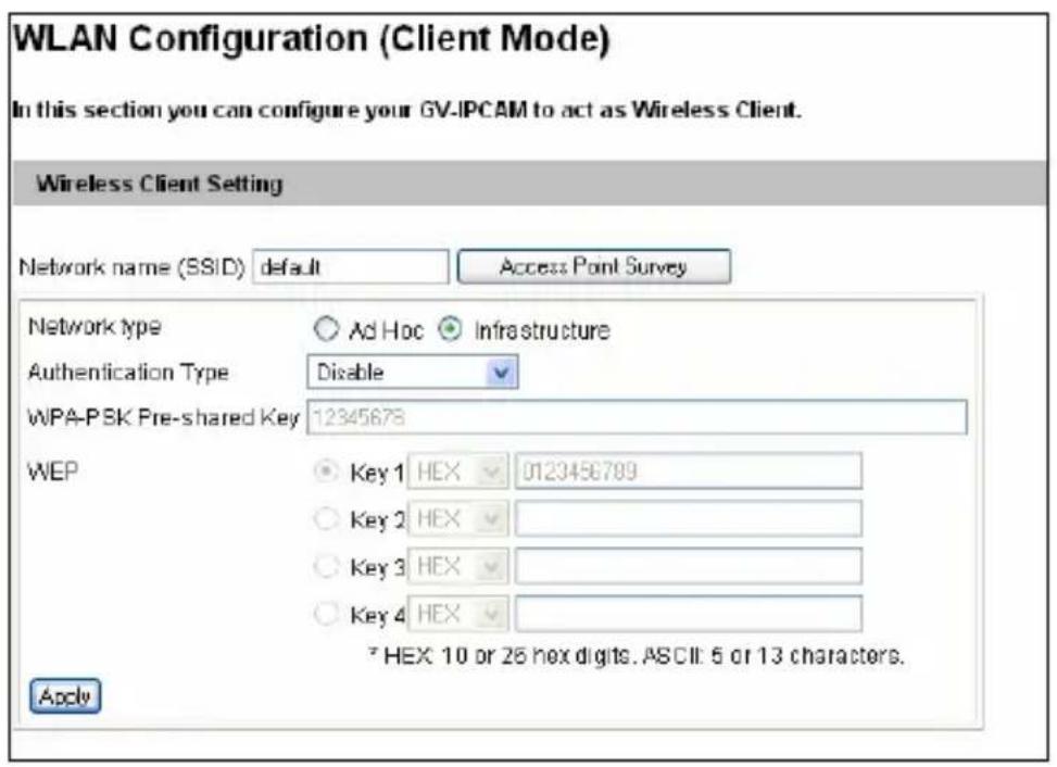
text_image
WLAN Configuration (Client Mode) In this section you can configure your GV-IPCAM to act as Wireless Client. Wireless Client Setting Network name (SSID) default Access Point Survey Network type Ad Hoc Infrastructure Authentication Type Disable WPA-PSK Pre-shared Key 12345678 WEP Key 1 HEX 0123456789 Key 2 HEX Key 3 HEX Key 4 HEX *HEX: 10 or 25 hex digits. ASCII: 5 or 13 characters. ApplyFigure 4-39
■ Network type: Select the network mode Ad Hoc or Infrastructure.
Infrastructure: Connect to the Internet via the Access Point. This mode further gives wireless access to the Internet or data sharing under a previously wired environment.
- Ad-Hoc: A Peer-to-Peer mode. This mode connects to other computer with the WLAN card, and does not need the Access Point to connect to each other.
■ Network name (SSID): The SSID (Service Set Identify) is a unique name that identifies a particular wireless network. Type SSID of the Wireless LAN group or Access Point you are going to connect to.
■ Access Point Survey: Click this button to search all the available Access Points (Infrastructure mode) and wireless stations (AD-Hoc mode) within the LAN.
■ Authentication Type: Select one of these network authentication and data encryption: Disable, WEP, WPAPSK-TKIP, WPAPSK-AES, WPA2PSK-TKIP or WPA2PSK-AES.
- Disabled: No authentication is needed within the wireless network.
- WEP (Wired Equivalent Privacy): A type of data encryption. Type up to four WEP Keys in HEX or ASCII format. Note that if you use HEX format, only digits 0-9 and letters A-F, a-f are valid.
- WPAPSK-TKIP and WPA2PSK-TKIP: Type WPA-PSK (Pre-Shared Key) for data encryption.
- WPAPSK-AES and WPA2PSK-AES: Type WPA-PSK (Pre-Shared Key) for data encryption.
For step-by-step instruction on wireless connection, see 2.1.3 Configuring the Wireless Connection.
Note:
- Your encryption settings must match those used by the Access Points or wireless stations with which you want to associate.
- When you lose the wireless access, you can still access the unit by connecting it to a LAN and search for the camera using GV IP Device Utility.
- When Ad Hoc is used, only WEP encryption is supported.
4.8.3 Advanced TCP/IP
This section provides the advanced TCP/IP settings, including DDNS Server, HTTP port, HTTPS, streaming port, UPnP, QoS and network connection check.
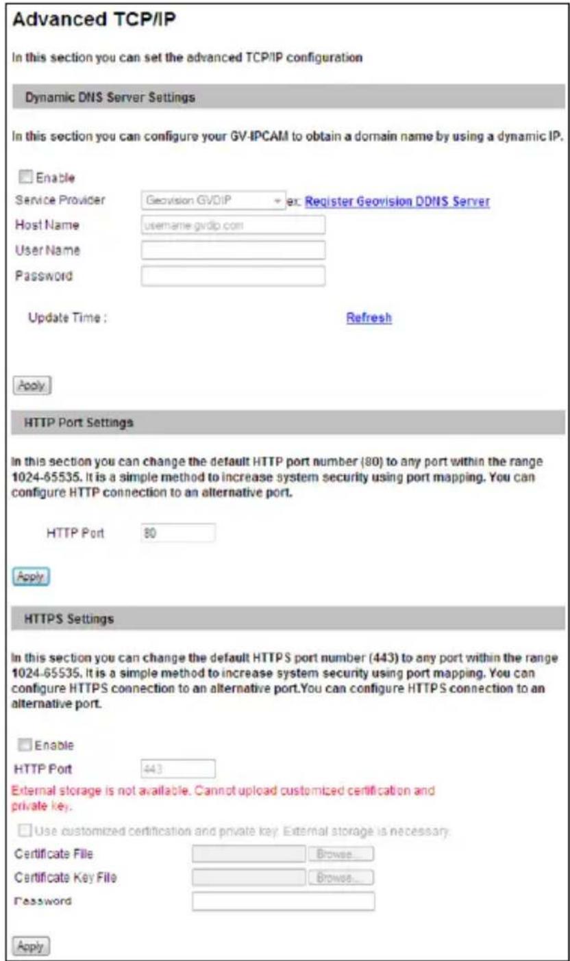
text_image
Advanced TCP/IP In this section you can set the advanced TCP/IP configuration Dynamic DNS Server Settings In this section you can configure your GV-IPCAM to obtain a domain name by using a dynamic IP. Enable Service Provider Geovision GVDIP ex Register Geovision DDNS Server Host Name username.gvdp.com User Name Password Update Time : Refresh Apply HTTP Port Settings In this section you can change the default HTTP port number (80) to any port within the range 1024-65535. It is a simple method to increase system security using port mapping. You can configure HTTP connection to an alternative port. HTTP Port 80 Apply HTTPS Settings In this section you can change the default HTTPS port number (443) to any port within the range 1024-65535. It is a simple method to increase system security using port mapping. You can configure HTTPS connection to an alternative port.You can configure HTTPS connection to an alternative port. Enable HTTP Port 443 External storage is not available. Cannot upload customized certification and private key. Use customized certification and private key. External storage is necessary. Certificate File Browse... Certificate Key File Browse... Password ApplyFigure 4-40A
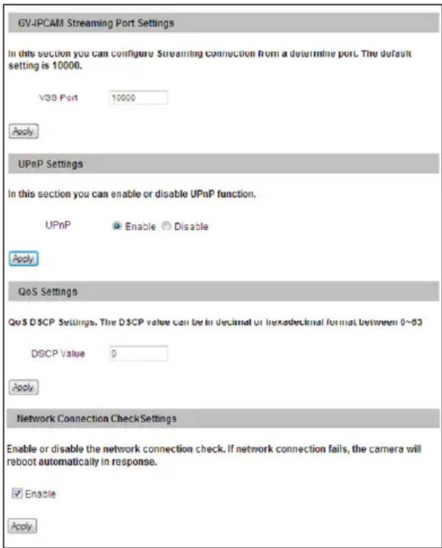
text_image
GV-IPCAM Streaming Port Settings In this section you can configure Streaming connection from a determine port. The default setting is 10000. V3S Port 10000 Apply UPnP Settings In this section you can enable or disable UPnP function. UPnP Enable Disable Apply QoS Settings QoS DSCP Settings. The DSCP value can be in decimal or hexadecimal format between 0~63 DSCP Value 0 Apply Network Connection Check Settings Enable or disable the network connection check. If network connection fails, the camera will reboot automatically in response. ✓ Enable ApplyFigure 4-40B
[Dynamic DNS Server Settings] DDNS (Dynamic Domain Name System) provides a convenient way of accessing the camera when using a dynamic IP. DDNS assigns a domain name to the camera, so that the Administrator does not need to go through the trouble of checking if the IP address assigned by DHCP Server or ISP (in xDSL connection) has changed. Before enabling the following DDNS function, the Administrator should have applied for a Host Name from the DDNS service provider's website. There are 3 providers listed in the camera: GeoVision GVDIP, GeoVision DDNS Server and DynDNS.org.
To enable the DDNS function:
- Enable: Enable the DDNS function.
- Service Provider: Select the DDNS service provider you have registered with.
- Host Name: Type the host name used to link to the camera. For the users of GeoVision DDNS Server, it is unnecessary to fill the field because the host name will be detected and brought up automatically.
- User Name: Type the username used to enable the service from the DDNS. The username should look similar to your host name. Depending on your service provider, you should add domain name (.dipmap.com, .gvdip.com or .org) after your user name, for example, alice.dipmap.com
- Password: Type the password used to enable the service from the DDNS.
- Click Apply.
[HTTP Port Settings] The HTTP port enables connection of the camera to the web. For security integration, the Administrator can hide the server from the general HTTP port by changing the default HTTP port of 80 to a different port number within the range of 1024 through 65535.
Note: The .pem file format is supported by Certificate and Private Key.
[GV-IPCAM Streaming Port Settings] The VSS port enables connecting the camera to the GV-System / GV-VMS. The default setting is 10000.
[UPnP Settings] UPnP (Universal Plug & Play) is a networking architecture that provides compatibility among networking equipment, software and peripherals of the 400+ vendors that are part of the Universal Plug and Play Forum. It means that they are listed in the network devices
table for the operating system (such as Windows XP) supported by this function. Enabling this function means you can connect to the camera directly by clicking on the camera listed in the network devices table.
[QoS Settings] The Quality of Service (QoS) is a bandwidth control mechanism that guarantees delay-sensitive data flows such as voice and video streams, obtain a certain amount of bandwidth to keep the streaming smooth.
To apply QoS to the camera, all network routers must support QoS and QoS must be enabled on these devices. To enable the QoS on the camera, enter a Differentiated Services Code Point (DSCP) value. This value is a field in an IP packet that enables different levels of services for the network traffic. When the video stream from the camera reaches a router, the DSCP value will tell the router what service level to be applied, e.g. the bandwidth amount. This value ranges from 0 to 63 in decimal format. The default value is 0, meaning QoS is disabled.
[Network Connection Check Settings] The camera checks for Internet connection, and reboots when it is disconnected from the Internet. This function is enabled by default.
Note: If you do not intend to connect the camera to the network, disable this function to prevent automatic reboot.
4.8.4 UMTS Settings
Not this function is not supported by GV-IPCAM H.265.
UMTS stands for Universal Mobile Telephone System. UMTS is a third-generation (3G) broadband, packet-based transmission of text, digitized voice, video, and multimedia at data rates up to 2 megabits per second. UMTS offers a consistent set of services to mobile computer and phone users, no matter where they are located in the world.
With a mobile broadband device (supporting UMTS, HSDPA, etc.) attached to the USB port on the rear panel, and with this UMTS function enabled, GV-Fisheye Camera can be accessed through wireless broadband. For supported mobile broadband devices, see Appendix E.
The Virtual Private Network (VPN) over a UMTS connection is also configurable on the setting page.
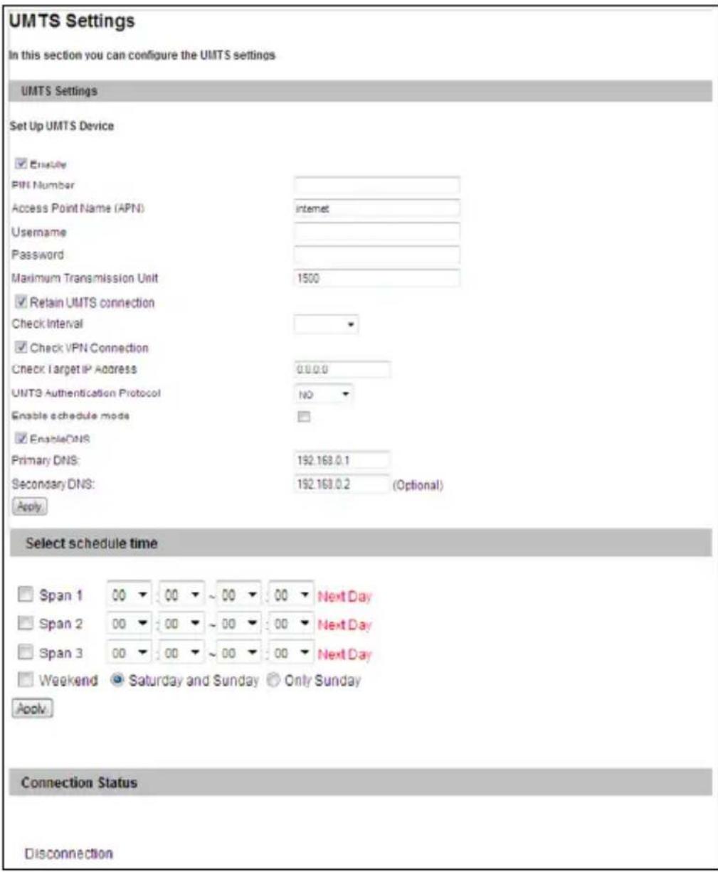
text_image
UMTS Settings In this section you can configure the UMTS settings UMTS Settings Set Up UMTS Device ✓ Enable PIN Number Access Point Name (APN) Internet Username Password Maximum Transmission Unit 1500 ✓ Retain UMTS connection Check Interval ✓ Check VPN Connection Check Target IP Address 0.0.0.0 UNT3 Authentication Protocol NO Enable schedule mode ✓ EnableDNS Primary DNS: 192.168.0.1 Secondary DNS: 192.168.0.2 (Optional) Apply Select schedule time □ Span 1 00 00 ~ 00 00 Next Day □ Span 2 00 00 ~ 00 00 Next Day □ Span 3 00 00 ~ 00 00 Next Day □ Weekend Saturday and Sunday Only Sunday Apply Connection Status DisconnectionFigure 4-41
■ PIN number: Type the PIN number that is provided by your network operator.
■ Access Point Name (APN): Type Access Point Name that is provided by your network operator.
■ Username: Type a valid username to enable the UMTS service from your network operator.
■ Password: Type a valid password to enable the UMTS service from your network operator.
■ Maximum Transmission Unit: Type the Maximum Transfer Unit (MTU). The default value is 1500.
■ Retain UMTS Connection: Select this option to check the UMTS connection status and use the drop-down list to specify the desired time length for check frequency. The GV-Video Server will rebuild the connection if disconnection is detected.
■ Enable VPN Connection: Select this option to enable the VPN (Virtual Private Network) connection. Type the target IP address in the Check Target IP Address field.
■ UMTS Authentication Protocol: Use the drop-down list to select the UMTS Authentication Protocol provided by your network operator.
■ Enable Schedule Mode: Starts the UMTS connection automatically based on the schedule you set in the Select Schedule Time section. Refer to 4.6 Recording Schedule for the same settings.
■ Enable DNS: Optional type up to two DNS servers of your network operator.
■ 3G Connection Status: Indicates the connection status of UMTS or VPN.
Note: When both WiFi and 3G signals are detected, the camera will connect to the network through WiFi.
4.8.5 IP Filter Settings
The Administrator can set IP filtering to restrict access to the camera.
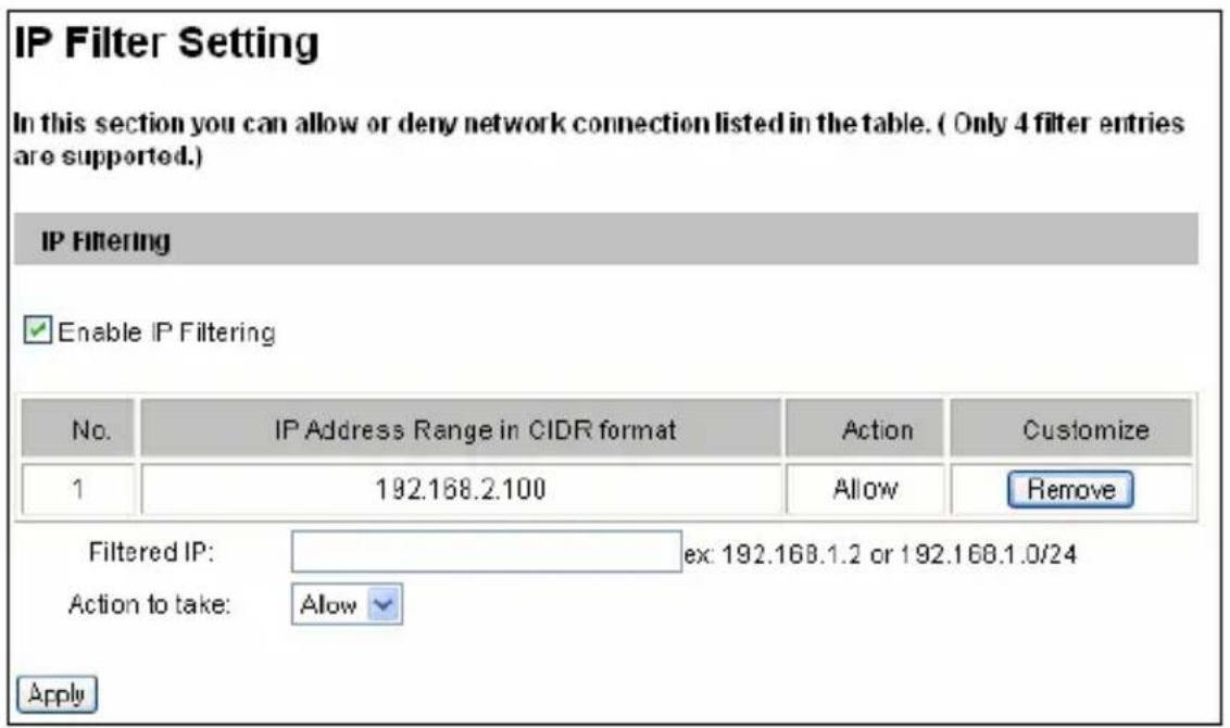
text_image
IP Filter Setting In this section you can allow or deny network connection listed in the table. ( Only 4 filter entries are supported.) IP Filtering Enable IP Filtering No. IP Address Range in CIDR format Action Customize 1 192.168.2.100 Allow Remove Filtered IP: ex: 192.168.1.2 or 192.168.1.0/24 Action to take: Allow ApplyFigure 4-42
To enable the IP Filter function:
- Enable IP Filtering: Enable the IP Filter function.
- Filtered IP: Type one IP address or a range of IP addresses you want to restrict the access.
- Action to take: Select the action of Allow or Deny to be taken for the IP address(es) you have specified.
- Click Apply.
4.8.6 SNMP Settings
The Simple Network Management Protocol (SNMP) allows you to monitor the status of the camera through SNMP network management software.
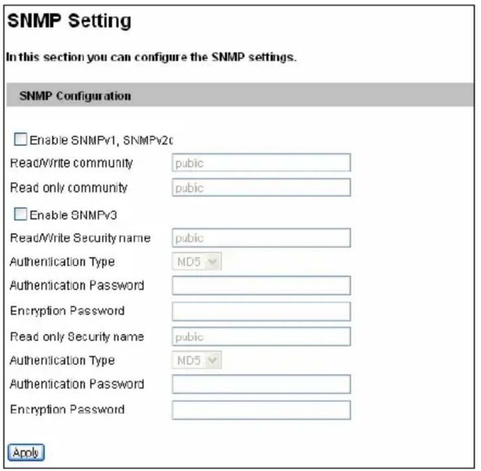
text_image
SNMP Setting In this section you can configure the SNMP settings. SNMP Configuration Enable SNMPv1, SNMPv2c Read/Write community pubic Read only community pubic Enable SNMPv3 Read/Write Security name pubic Authentication Type MD5 Authentication Password Encryption Password Read only Security name pubic Authentication Type MD5 Authentication Password Encryption Password ApplyFigure 4-43
- Select Enable SNMPv1 SNMPv2c to enable the function.
- To enable access to Read/Write community, type a community string. This will serve as a password to allow read and write access to the camera from the SNMP software.
- To enable Read only community, type a community string to allow read-only access to the camera from the SNMP software.
- For a more secured connection, select Enable SNMPv3 to enable SNMP version 3.
- To enable access to SNMPv3 Read/Write community, type a community string.
- Select an Authentication Type to use for SNMP requests.
- Type the Authentication Password and Encryption Password. You will need to type these passwords in the SNMP software to be able to access the camera.
- To enable access to SNMPv3 Read only community, follow steps 5 \~ 7.
- Click Apply to save the settings.
4.9 Management
The Management section includes the settings of data and time and user account. You can also view the firmware version and execute certain system operations.
4.9.1 Date & Time Settings
The date and time settings are used for date and time stamps on the image.
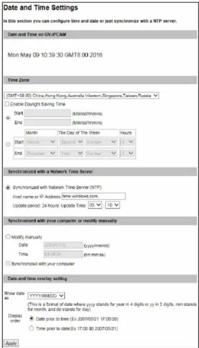
text_image
Date and Time Settings in this section you can configure time and date or just synchronize with a NTP server. Date and Time on GV-PCAM Mon May 09 10:39:30 GMT8:00 2016 Time Zone (GMT+08:00) China,Hong Kong,Australia Western,Singapore,Taiwan,Russia Enable Daylight Saving Time Start (MM/00/hn/mm) End (MM/00/hn/mm) Month The Day of The Week Hours Start Month Second Sunday T End Number Final Sunday T Synchronized with a Network Time Server Synchronized with Network Time Server (NTP) Host name or IP Address: time.windows.com Update period: 24 hours; Update Time: 05 : 10 Synchronized with your computer or modify manually Modify manually Date 2007/07/15 (yyyy/mm/dd) Time 04:26:54 (hh:mm:ss) Synchronized with your computer Date and time overlay setting Show date as YYYY/MM/DD (This is a format of date where yyyy stands for year in 4 digits or yy in 2 digits, mm stands for month, and dd stands for day) Display order Date prior to time (Ex.2007/05/21 17:00:00) Time prior to date(Ex.17:00:00 2007/05/21) ApplyFigure 4-44
[Date & Time on GV-IP Camera] Displays the current date and time on the camera.
[Time Zone] Sets the time zone for local settings. Select Enable Daylight Saving Time to automatically adjust the camera for daylight saving time. Type the Start Time and End Time to enable the daylight saving function. For GV-BX12201 firmware V1.02 or later, you can also select which day of a week within a month to apply the DST setting.
To play back, see 5.2.4 Playback of Daylight Saving Time Events. To automatically synchronize the Daylight Saving Time with the GV-System, see 7.1.1 Customizing IP Camera Settings on GV-System.
[Synchronized with a Network Time Server] By default, the camera uses the timeserver of time.windows.com to automatically update its internal clock every 24 hours. You can change the host name or IP setting to the timeserver of interest, and specify a time for time update.
[Synchronized with your computer or modify manually] Manually changes the camera's date and time. Or, synchronize the camera's date and time with those of the local computer.
[Date and Time Overlay Setting] Select the display format of date and time stamps on the image. For this function to work, you must also enable the Overlaid with date stamps and Overlaid with time stamps options in Figure 4-2.
4.9.2 Storage Settings
Based on Linux file system, the camera supports memory cards for video and audio recordings. You need to format the storage device by using the following Storage Settings. After being formatted, the storage device will be ready to use by Linux OS of the camera.
Note: The Target Series does not support memory cards. You can store recordings to a connected NAS server instead. Refer to Network Neighborhood Settings below.
Storage Settings
In this section you can configure the disk storage to archive videos and events.
The recording data may be lost if the power supply is interrupted during recording.
Storage Settings
Name GVBL1510

Enable recycling
Stop recording or recycle disk when free space of disk is smaller than 256M

Keep days (1-255) 30
Record Disk Type Default

Enable debug message to the storage.

Enable auto formatting when disk or partition is unable to record.
Apply
Network Neighborhood Settings
Server URL/IP Address
Enable
Search
UserName
Password
Apply
Disk Information
| Disk No | Total Size | Hed Size | Free space | Utilization | Remove | Format |
| Disk0 | 1862 852 | 2.841 | 1860.010 | 0% | Remove | Format |
Partition Information
| Disk No. | Partition No. | Total Size | Used Size | Free space | Utilization | Status | Other |
| Disk0 | 10 | 195.298 | 0.196 | 195.102 | 0% | OK | Format |
| Disk0 | 11 | 195.298 | 0.183 | 195.115 | 0% | OK | Format |
| Disk0 | 12 | 195.298 | 0.183 | 195.115 | 0% | OK | Format |
| Disk0 | 13 | 195.298 | 0.183 | 195.115 | 0% | OK | Format |
| Disk0 | 14 | 195.148 | 0.183 | 194.965 | 0% | OK | Format |
| Disk0 | 5 | 195.298 | 1.160 | 194.137 | 0% | OK | Format |
| Disk0 | 6 | 195.298 | 0.182 | 196.116 | 0% | OK | Format |
| Disk0 | 7 | 195.298 | 0.183 | 195.115 | 0% | OK | Format |
| Disk0 | 8 | 195.298 | 0.183 | 195.115 | 0% | OK | Format |
| Disk0 | 9 | 195.298 | 0.183 | 195.115 | 0% | OK | Format |
Network Neighborhood Disk Information
| Disk No. | Total Size | Used Size | Free space | Utilization |
| No HDD connected | ||||
(Unit: Gigabyte)
Figure 4-45
[Storage Settings]
Name: Type the name of the storage device. The name can only contain English letters (of upper or lower cases), numerals, slashes, and hyphens.
Note: The setting of the device name is for GV-NAS System only.
■ Enable recycling: If Enable recycling is selected, when the space of the storage device is lower than the specified space, the system will overwrite the oldest recorded files. If Enable recycling is not selected, the system will stop recording when the specified space is reached.
- Keep days (1-255): Specify the number of days to keep the files from 1 day to 255 days. When both Keep days and Enable recycling are selected, the system applies whichever condition comes first. For example, if the specified smallest amount of storage space comes earlier than the designated keep days, then recycle is applied first.
■ Enable debug message to the storage: Note this function is not supported for Target Series. Debug message (see 4.9.4 Log Information) is deleted after reboot. Select this option to store log information to an inserted storage device.
■ Enable auto formatting when disk or partition is enabled to record: Note this function is not supported for Target Series. Select this option for the camera to automatically format the storage device when there is error during recording.
[Network Neighborhood Settings]
You can record to a connected NAS server.
Note:
- Make sure your camera's video settings adhere to the following:
• VBR is set to Good
● Maximal Bit Rate is set to the following:
| Camera Type Max. Bit Rate | |
| 1.3 M 6 Mbit or lower | |
| 2 MP / 3 MP / 4 MP / 5 MP 8 | Mbit or lower |
- For optimal performance and compatibility, it is highly recommended to use a GV-NAS System.
- It is highly recommended to use a NAS server that supports a quota function, with which a separate quota is allocated to each camera.
- GV-NAS System is not supported by GV-BX12201, GV-EBL2101, GV-BX2600 and GV-IPCAM H.265.
- GV-IP Camera and GV-Target Series do not support recording to shared folders of a Windows-based server.
- To avoid dropping frame rate, when GV-EFD3101 / GV-EVD3100 and GV-EFD5101 / GV-EVD5100 are connected to GeoVision software, and recording to NAS with the resolution of 2048 x 1536 and 2592 x 1944 at 30 fps, it is highly recommended to change its Max. Bit Rate to 6 Mbit in VBR setting.
To connect record to GV-NAS Systems, follow the steps below.
- Under Network Neighborhood Settings, select Enable and click the Search button to search for available NAS servers.
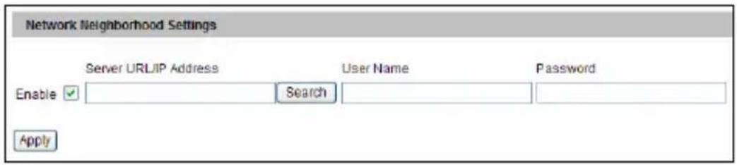
text_image
Network Neighborhood Settings Server URLIP Address User Name Password Enable Search ApplyFigure 4-46
- Type the username and password, and click Select.
| Samba Domain List | ||||
| Group | Domain | Username | Password | Selection |
| WORKGROUP | GV-NAS2008 | Cam01 | ●●●●●●● | Select |
Figure 4-47
Note: Depending on the models of GV-NAS System, up to 16 default user accounts (username: Cam01 – Cam16; password: 12345678) are available. The storage limitation and recycle is applied on a user basis. It is recommended to use one user account exclusively for recording of one GV-IP Camera to avoid uneven data recycle.
- Select a folder to store recordings, and click OK.
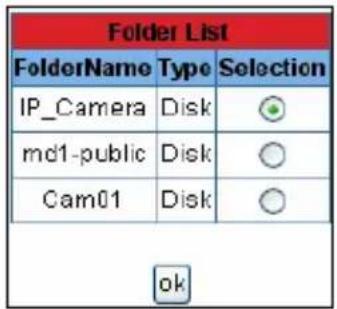
text_image
Folder List FolderName Type Selection IP_Camera Disk md1-public Disk Cam01 Disk okFigure 4-48
- Click Apply. Once connected, the disk status will display.
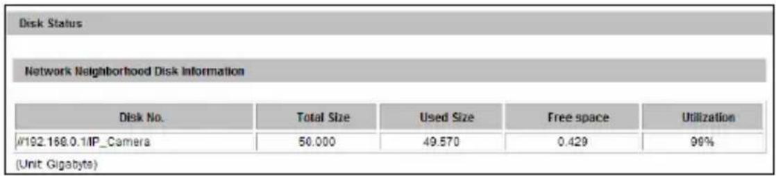
text_image
Disk Status Network Neighborhood Disk Information Disk No. Total Size Used Size Free space Utilization #192.168.0.1MP_Camera 50.000 49.570 0.429 99% (Unit: Gigabytes)Figure 4-49
Tip: Instead of searching for available NAS servers, you can also type the storage path directly.
- Type the Server URL/ IP Address in this format: \NAS IP Address\Storage Folder. For example, \192.168.0.1\IP_Camera. This GV-IP Camera will be recorded to a default shared folder named "IP_Camera" in the GV-NAS System.
- Type the username and password. For GV-NAS System, you can type any of default usernames Can01 to Cam16, and password is 12345678.
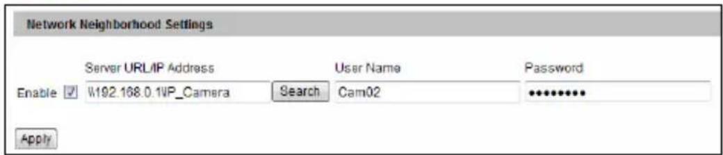
text_image
Network Neighborhood Settings Server URL/IP Address User Name Password Enable ✓ W192.168.0.1VP_Camera Search Cam02 ••••••••• ApplyFigure 4-50
For details on GV-NAS System, refer to GV-NAS System Quick Start Guide.
[Disk Information]
Note this function is not supported for Target Series. This section shows the details of the attached storage device. Use the Format/Remove button to format or unload a storage device. For detail steps, see Partition Information below.
[Partition Information]
Note this function is not supported for Target Series. This section shows the partition details of the attached storage device.
To add a storage device:
- Insert the storage device to the camera.
- Click the Format button.
- After the format is complete, the partition information will display. The maximum space for one partition is 200 GB.
To remove a storage device:
- Click the Remove button.
- When you are prompted to ensure the action, click Yes. The page will be refreshed and the partition information will be cleaned.
- Remove the storage device from the camera.
The storage device status is indicated in the status column:
| Status Description | |
| Formatting The storage device is being formatted. | |
| Unknown | The camera can not recognize the format of the storage device or the device can not be found. |
| OK Storage formatting is successful. | |
| Try Mount | The camera is attempting to connect to the storage device. |
| Error File System | There is a recording error in the storage device. All the recording data is inaccessible under the status. |
| Read Only | The storage device cannot be written due to abnormal power disruption. |
| Repairing | The system is attempting to repair the recording data. |
Note:
- If Enable Recycle is selected, the available space of the storage device must be higher than the space you specified at the Stop recording or recycle disk when free space of disk is smaller than x option. Otherwise no video will be recoded.
- The recording data may be lost if you remove the storage device during recording.
- If you do not remove the storage device properly, the data cannot be read in another computer. In this case, re-plug the storage device back to the camera. The system will repair the data automatically. When the system is repairing the data, the Remove field will display "Repairing".
- To upgrade the firmware from versions earlier than V2.07 to the latest version, be sure to back up the recordings on the camera's storage device first before the upgrade, and re-format the memory card after the upgrade. If you have not done so, this warning message appears when you view the Monitoring or Storage Settings' Web interface:
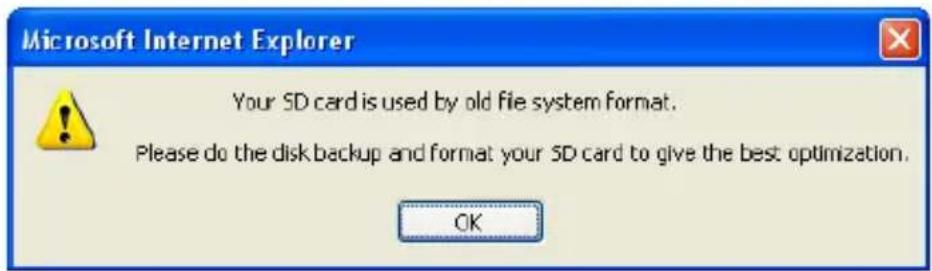
text_image
Microsoft Internet Explorer Your SD card is used by old file system format. Please do the disk backup and format your SD card to give the best optimization. OKFigure 4-51
4.9.3 User Account
You can change the login name and password of Administrator and Guest. The default Administrator login name and password are admin; the default Guest login name and password are guest. To allow a Guest user log in without entering name and password, select Disable authentication for guest account. To prevent automatic logout of an Administrator / Guest account user after reboot, select Disable auto logout when reboot.
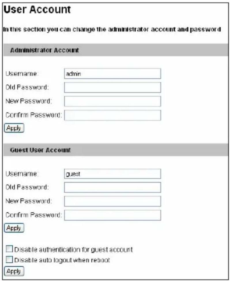
text_image
User Account In this section you can change the administrator account and password Administrator Account Username: admin Old Password: New Password: Confirm Password: Apply Guest User Account Username: guest Old Password: New Password: Confirm Password: Apply Disable authentication for guest account Disable auto logout when reboot ApplyFigure 4-52
4.9.4 Log Information
The log information contains dump data that is used by service personnel for analyzing problems. The logs available may vary depending on the camera model.

text_image
Log Information In this section you can see all system activities. Startup time log In this section you can see latest booting time of system. Debug Messages This section shows the data used for debugging. Oct 3 13:27:17 Video Server[1067]: (1135) ALG_vidEncSetDynamicParams[1854]: VidEnc: mkNyOutEnable =0 Oct 3 13:27:17 Video Server[1067]: (1135) ALG_vidEncSetDynamicParams[1856]: VidEnc: encStatus.bufInfo.minNumInBufs is 2 Oct 3 13:27:17 Video Server[1067]: (1135) ALG_vidEncSetDynamicParams[1858]: VidEnc: minInBufSize[0] is [3145728] Oct 3 13:27:17 Video Server[1067]: (1135) ALG_vidEncSetDynamicParams[1858]: VidEnc: minInBufSize[1] is [1572064] Oct 3 13:27:17 Video Server[1067]: (1135) ALG_vidEncSetDynamicParams[1860]: VidEnc: encStatus.bufInfo.minNumOutBufs is 2 Oct 3 13:27:17 Video Server[1067]: (1135) ALG_vidEncSetDynamicParams[1862]: VidEnc: minOutBufSize[0] is [4718592] Oct 3 13:27:17 Video Server[1067]: (1135) ALG_vidEncSetDynamicParams[1862]: VidEnc: minOutBufSize[1] is [800] Oct 3 13:27:22 Video Server[1067]: (1135) davinci_encoder_rate_control_update[6208]: Encoder Stream Dynamic Params Update: [Quantization]: QP Down to [37] from [36] ---- Oct 3 13:27:22 Video Server[1067]: (1135)Figure 4-53
4.9.5 Tools
You can execute certain system operations and view the firmware version.
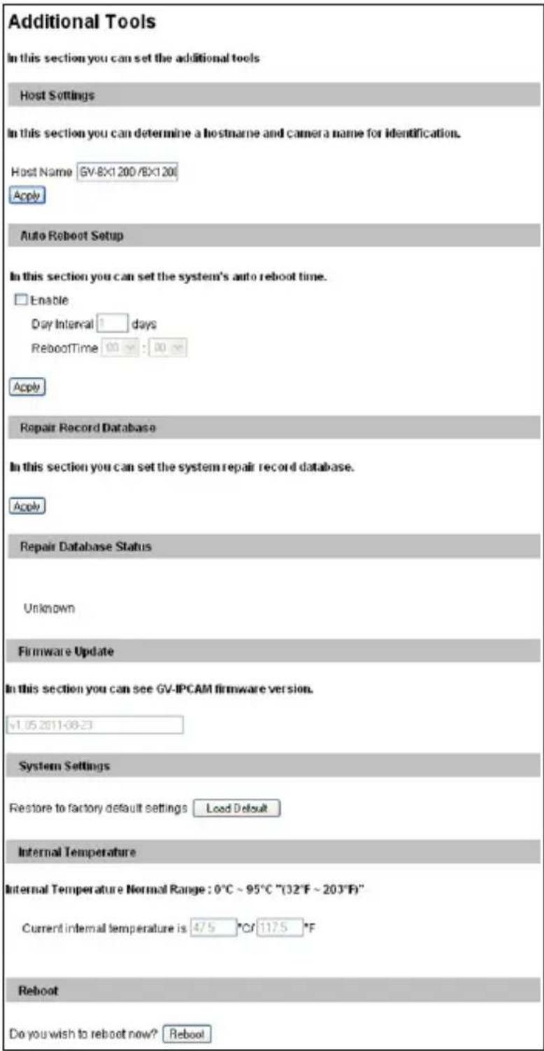
text_image
Additional Tools In this section you can set the additional tools Host Settings In this section you can determine a hostname and camera a name for identification. Host Name GV-8X1200/BX1200 Apply Auto Reboot Setup In this section you can set the system's auto reboot time. Enable Day Interval 1 days RebootTime 00 ns : 00 ns Apply Repair Record Database In this section you can set the system repair record database. Apply Repair Database Status Unknown Firmware Update In this section you can see GV-IPCAM firmware version. v1.05.2011-08-23 System Settings Restore to factory default settings Load Default Internal Temperature Internal Temperature Normal Range : 0°C ~ 95°C "(32°F ~ 203°F)" Current internal temperature is 4/5 °C/ 1175 °F Reboot Do you wish to reboot now? RebootFigure 4-54
[Host Settings] Enter a descriptive name for the camera.
[Auto Reboot Setup] Select Enable to activate automatic reboot and specify the time for reboot in the sub fields.
■ Day Interval: Type the day interval between each reboot.
■ Reboot Time: Use the drop-down lists to specify the time for automatic reboot.
[Repair Record Database] Note this function is not available for Target Series. Click Apply to repair the database when errors occur while playing back the recordings with the Remote ViewLog player. Problems can occur when there are errors in firmware or damages to the micro SD card.
[Database Status] Note this function is not available for Target Series. Displays the repairing status of database.
[Firmware Update] This field displays the firmware version of the camera.
[System Settings]
- Load Default: Clicking the Load Default button to restore factory default settings. After applying the default settings configure the camera's network setting again.
- Load Default Without Network: Clicking the Load Default without Network button to restore factory default settings without changing the camera's network settings.
[Temperature Status] Note this function is not available for Target Series (except for GV-EFD2101/3101/5101 and GV-EVD2100/3100/5100), Cube Camera and Advanced Cube Camera. Displays the current chipset temperature inside the camera.
[Reboot] Clicking the Reboot button will make the camera perform software reset.
4.9.6 Language
Note this function is not available in GV-PTZ010D.
You can select the language for the Web interface.
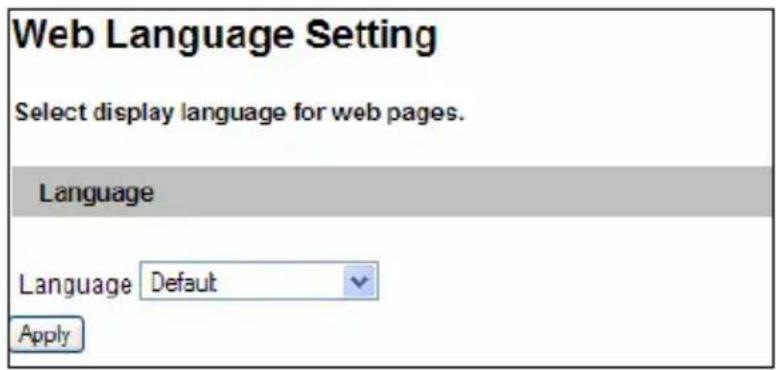
text_image
Web Language Setting Select display language for web pages. Language Language Default ApplyFigure 4-55
Use the Language drop-down list to select a language for the Web interface. By default, the language on the Web interface will be the same with the one used for the operating system.
Chapter 5 Recording and Playback
Note that Recording and Playback function is not available for Target Series.
The camera can record video and audio directly to the memory card. You can play back the recorded files on the GV-System / GV-VMS or over the TCP/IP network.
Note: See Note for Recording at the beginning of the manual.
5.1 Recording
To enable the recording function:
- Insert the memory card to the camera. See "To add a memory card", 4.9.2 Storage Settings.
- If you like to set up the pre-recording, post-recording or audio recording, see 4.1.1 Video Settings.
- If you like to set up the schedule for video recording or I/O monitoring, see 4.6 Recording Schedule.
- If you like to configure the areas and sensitivity values for motion detection, see 4.1.2 Motion Detection.
- If you want the recording to be triggered by input device, configure the operation of input device. See 4.3.1 Input Settings.
- To start recording and I/O monitoring, see 4.5 Monitoring.
The camera will start recording in case of motion detection, I/O trigger, or during the scheduled time.
5.2 Playback
These methods are available to play back the video files recorded at the camera:
- Playback from the memory card by connecting it directly to the GV-System / GV-VMS through a card reader
- Playback by using the Remote ViewLog function over the TCP/IP network
- Playback by using the recorded files downloaded from built-in FTP Server
5.2.1 Playback from the Memory Card
You can play back the files recorded at the GV-IP Camera by connecting the memory card to GV-System / GV-VMS through a card reader. However, the videos on GV-IP devices are recorded in the Linux format and GV-System / GV-VMS runs on a Windows-based computer. For Linux files to be readable and accessible on Windows, we use the Ext2Fsd program. Follow the steps below to download, install and execute the Ext2Fsd program.
IMPORTANT:
- Due to the compatibility issue, the Ext2Fsd program is required for GV-IP Camera firmware V2.07 or later.
- The Ext2Fsd program only works on Windows 2000, XP, 2003, vista, 7, 8 and Server 2012 (32-bit and 64-bit).
-
The Ext2Fsd program is subject and under term/condition of The GNU General Public License version 2 (GPLv2). Please read http://www.gnu.org/licenses/gpl-2.0.html before installation.
-
Install the Ext2Fsd from the Software DVD.
Note: If you are using Windows 8 or Windows Server 2012, change its compatibility before installing the Ext2Fsd program:
A. Right-click the Ext2Fsd program and select Properties. This dialog box appears.
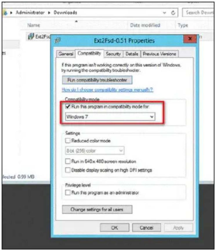
text_image
Ext2Fsd-0.51 Properties General Compatibility Security Details Previous Version If this program isn't working correctly on this version of Windows. by running the compatibility troubleshooter. Run compatibility troubleshooter How do I choose compatibility settings internally? Compatibility mode ✓ Run this program in compatibility mode for: Windows 7 Settings □ Reduced color mode 8 bit (256) color □ Run in 640 x 400 screen resolution □ Disable display scaling on high DPI settings Privilege level □ Run this program as an administrator Change settings for all users OK Cancel ApplyFigure 5-1
B. Select the Compatibility tab.
C. Select Windows 7 using the drop-down list.
- On Your desktop, click Start, select Programs, locate the Ext2Fsd folder and select Ext2 Volume Manager. All the connected drives are shown.

text_image
Ext2 Volume Manager File Edit Tools Help Volume Type File system Total size Used size Codepage Physical object (D:) Basic NTFS 97 GB 24 GB Device\HarddiskVolume1 (C:) Basic NTFS 96 GB 16 GB Device\HarddiskVolume2 (E:) Basic NTFS 737 GB 198 GB Device\HarddiskVolume3 Basic EXT3 195 GB 195 GB Device\HarddiskVolume4 Basic EXT3 195 GB 195 GB Device\HarddiskVolume5 Basic EXT3 195 GB 195 GB Device\HarddiskVolume6 Basic EXT3 195 GB 195 GB Device\HarddiskVolume7 Basic EXT3 195 GB 195 GB Device\HarddiskVolume8 Type File system Total size Used size Codepage Partition type DISK.0 (D:) Basic NTFS 97 GB 24 GB HPFS/NTFS (E:) Basic NTFS 737 GB 199 GB HPFS/NTFS (C:) Basic NTFS 96 GB 16 GB HPFS/NTFS DISK.1 Basic EXT3 195 GB 195 GB Linux Basic EXT3 195 GB 195 GB Linux Basic EXT3 195 GB 195 GB Linux Basic EXT3 195 GB 195 GB Linux Basic EXT3 195 GB 195 GB Linux Basic EXT3 195 GB 195 GB Linux VOLUME: (D:) NTFS \Device\HarddiskVolume1 Oct 18,2013 15:58:11Figure 5-2
- For the first-installation, execute the Ext2Fsd Service.
A. From the Ext2 Volume Manager window, select Tools and select Service Management. This dialog box appears.
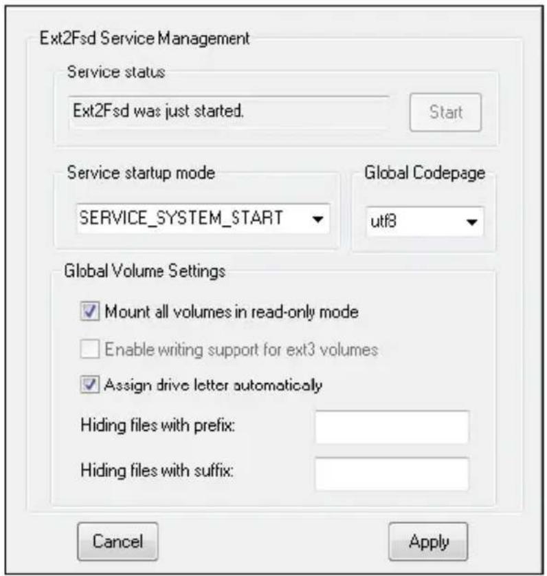
text_image
Ext2Fsd Service Management Service status Ext2Fsd was just started. Start Service startup mode SERVICE_SYSTEM_START Global Codepage utf8 Global Volume Settings ✓ Mount all volumes in read-only mode ☐ Enable writing support for ext3 volumes ✓ Assign drive letter automatically Hiding files with prefix: Hiding files with suffix: Cancel ApplyFigure 5-3
B. Click Apply.
- Mount the storage drive to your computer.
A. From the Ext2Fsd Volume Manager window, right-click the storage drive and select Ext2 Management. This dialog box appears.
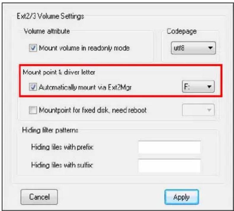
text_image
Ext2/3 Volume Settings Volume attribute Codepage ✓ Mount volume in readonly mode utf8 Mount point & driver letter ✓ Automatically mount via Ext2Mgr F: ✓ Mountpoint for fixed disk, need reboot Hiding filter patterns Hiding files with prefix: Hiding files with suffix: Cancel ApplyFigure 5-4
B. Under the Mount point & driver letter section, select Automatically mount via Ext2Mgr, specify a disk drive using the drop-down list and click Apply.
C. On the Ext2 Volume Manager window, the storage drive is successfully mounted to your computer when it is indicated with the disk drive you specified.
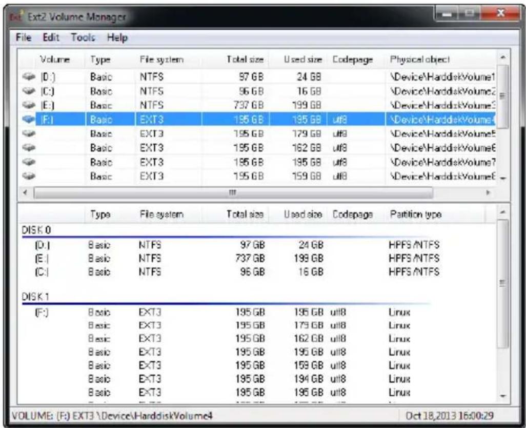
text_image
Ext2 Volume Manager File Edit Tools Help Volume Type File system Total size Used size Codepage Physical object (D:) Basic NTFS 97 GB 24 GB \Device\HarddiskVolume1 (C:) Basic NTFS 96 GB 16 GB \Device\HarddiskVolume2 (E:) Basic NTFS 737 GB 199 GB \Device\HarddiskVolume3 (F:) Basic EXT3 195 GB 195 GB utf8 \Device\HarddiskVolume4 Basic EXT3 195 GB 179 GB utf8 \Device\HarddiskVolume5 Basic EXT3 195 GB 162 GB utf8 \Device\HarddiskVolume6 Basic EXT3 195 GB 195 GB utf8 \Device\HarddiskVolume7 Basic EXT3 195 GB 159 GB utf8 \Device\HarddiskVolume8 Type File system Total size Used size Codepage Partition type DISK 0 (D:) Basic NTFS 97 GB 24 GB HPFS/NTFS (E:) Basic NTFS 737 GB 199 GB HPFS/NTFS (C:) Basic NTFS 96 GB 16 GB HPFS/NTFS DISK 1 (F:) Basic EXT3 195 GB 195 GB utf8 Linux Basic EXT3 195 GB 179 GB utf8 Linux Basic EXT3 195 GB 162 GB utf8 Linux Basic EXT3 195 GB 195 GB utf8 Linux Basic EXT3 195 GB 159 GB utf8 Linux Basic EXT3 195 GB 194 GB utf8 Linux Basic EXT3 195 GB 195 GB utf8 Linux VOLUME: (F) EXT3 \Device\HarddiskVolume4 Oct 18,2013 16:00:29Figure 5-5
- Access the recording files from the specified drive of your computer.
5.2.2 Playback over Network
With the Remote ViewLog function, you can play back the files recorded at the camera over TCP/IP network.
- The camera needs to allow the remote access with ViewLog Server activated. See 4.4.7 ViewLog Server.
- For the first-time user, run the Remote ViewLog program from the Software DVD. Next time whenever you like to use this remote playback function, access this option from the camera's Web interface.
- When the Remote ViewLog player is open, you will be prompted to select Remote ViewLog Service or Remote Storage System. Select Remote ViewLog Service.
- When this dialog box appears, type the camera's IP address, login ID and password. Keep the default port 5552 or modify it if necessary.
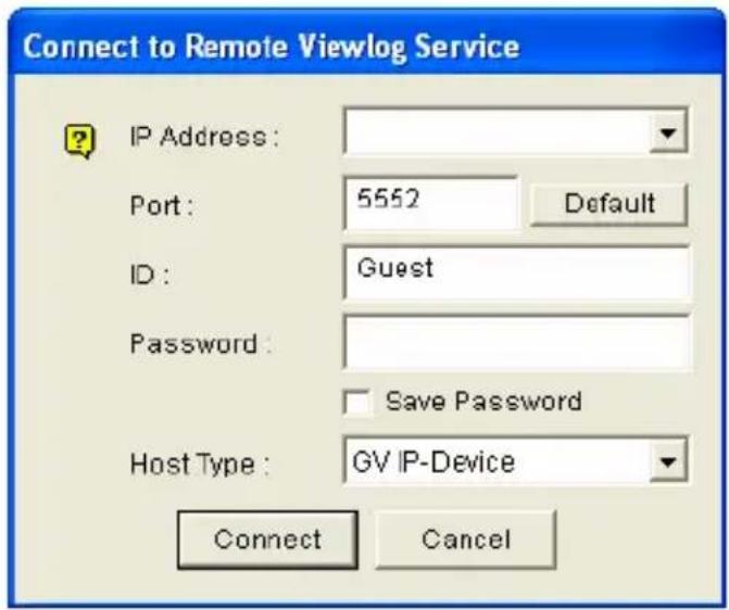
text_image
Connect to Remote Viewlog Service IP Address : Port: 5552 Default ID: Guest Password: Save Password Host Type: GV IP-Device Connect CancelFigure 5-6
-
In the Host Type field, select GV-IP Device.
-
Click Connect to access the files of the camera for playback.
5.2.3 Access to the Recorded Files through FTP Server
The built-in FTP Server allows you to download the recorded files saved on the memory card. You can play back the downloaded files of AVI format with Media Player. For details to download files, see [Act as FTP Server], 4.4.2 FTP.
Note: To play back videos, ensure you have installed Geovision codec on the computer. The codec is available on the Software DVD. If you have installed the Remote Playback player on the computer, it is not required to install the codec.
5.2.4 Playback of Daylight Saving Time Events
On GV-System, you can retrieve the events recorded during the Daylight Saving Time (DST) period from the camera for playback. You can also connect the memory card to GV-System for playback.
The following instructions describe how to retrieve the recorded files from the camera over network. If you like to use the memory card for playback, first follow the instructions in 5.2.1 Playback Using the Memory Card to load the recorded files to ViewLog, and then follow Steps 4-5 below to play back DST events.
- The camera must allow the remote access with ViewLog Server activated. See 5.3.7 ViewLog Server.
- To remotely connect to the camera from GV-System, click the Tools button and select Remote ViewLog Service. The Connect to Remote ViewLog Service dialog box appears.
- Enter the connection information of the camera, and click Connect. Once the connection is established, the video events will be displayed on the Video Event list.
- On the Date Tree, select the date of Daylight Saving Time. A separate DST subfolder will be displayed as illustrated below.
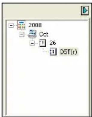
flowchart
graph TD
    A["2008"] --> B["Oct"]
    B --> C["26"]
    C --> D["DST(r)"]
Figure 5-7
- On the Video Event list, select desired events, and click the Play button to start.
Note:
- The playback function is only compatible with the GV-System of version 8.3 and later.
- The AVI file recorded during the DST period is named with the prefix "GvDST", e.g. GvDST20081022xxxxxxxxxx.avi, to differentiate from the regular AVI file named with the prefix "Event", e.g. Event20081022xxxxxxxxxx.avi.
Chapter 6 Advanced Applications
This chapter introduces more advanced applications.
6.1 Upgrading System Firmware
GeoVision periodically releases updated firmware on the website. Simply download the new firmware into the camera using the Web interface or IP Device Utility included in the Software DVD.
Important Notes before You Start
Before you start updating the firmware, please read these important notes:
- To update the camera firmware from versions earlier than V2.07 to the latest version, back up the recordings on the storage device to another device first before the upgrade.
- If you use the IP Device Utility for firmware upgrade, the computer used to upgrade firmware must be under the same network of the camera.
- Stop monitoring of the camera.
- Stop all the remote connections including Center V2, Vital Sign Monitor, ViewLog Server and 3GPP/RTSP.
- Stop the connection to GV-System.
- While the firmware is being updated,
A) the power supply must not be interrupted, and
B) do not unplug the Ethernet cable if the cable is the source of power supply (Power over Ethernet or PoE supported).
WARNING: The interruption of power supply during updating causes not only update failures but also damages to the camera. In this case, please contact your sales representative and send your device back to GeoVision for repair.
- Do not turn the power off within 10 minutes after the firmware is updated.
- If firmware upgrade fails, manually restore the camera to its default settings. For details, see Loading Factory Default in the corresponding Hardware Manual.
- Since the firmware adopts different storage format from V2.07 onward, be sure to re-format the memory card after firmware upgrade. If you have not done so, this warning message appears when you view the Monitoring or Storage Settings' Web interface:
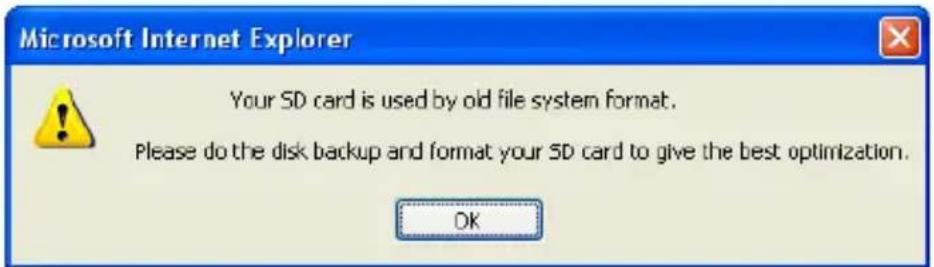
text_image
Microsoft Internet Explorer Your SD card is used by old file system format. Please do the disk backup and format your SD card to give the best optimization. OKFigure 6-1
6.1.1 Using the Web Configuration Interface
- In the Live View window, click the Show System Menu button (No. 9, Figure 3-3) and select Remote Config. This dialog box appears.
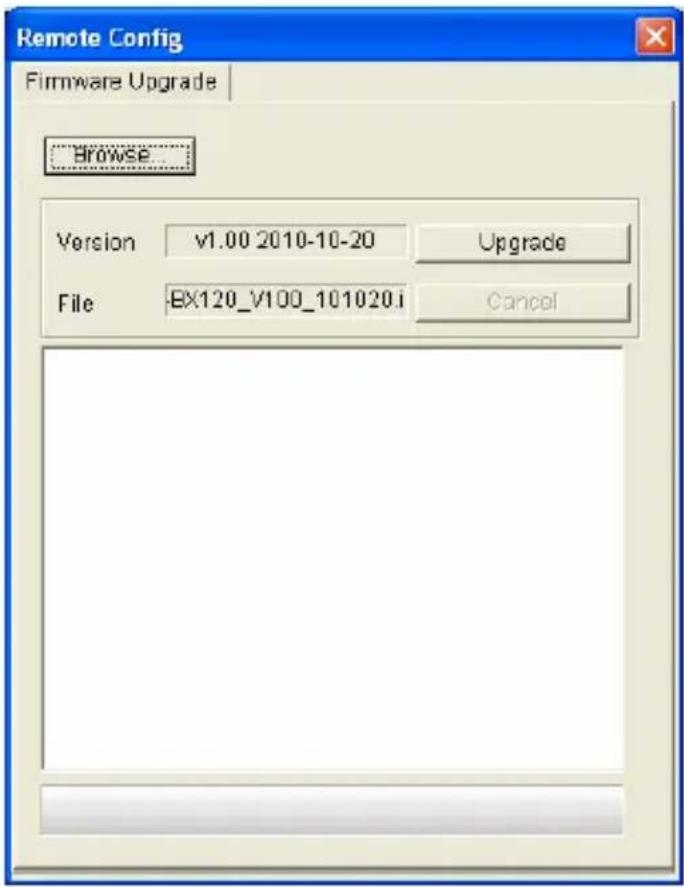
text_image
Remote Config Firmware Upgrade Browse... Version v1.00 2010-10-20 Upgrade File BX120_V100_101020.i CancelFigure 6-2
- Click the Browse button to locate the firmware file (.img) saved at your local computer.
- Click the Upgrade button to start the upgrade.
6.1.2 Using the IP Device Utility
The IP Device Utility provides a direct way to upgrade the firmware to multiple units of the GV-IPCAM. Note the computer used to upgrade firmware must be under the same network of the camera.
- Insert the Software DVD, select GeoVision IP Device Utility, and follow the onscreen instructions to install the program.
- Double-click the IP Device Utility icon created on your desktop. This dialog box appears.
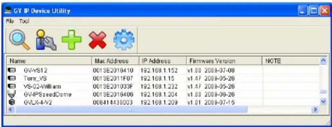
text_image
GV IP Device Utility File Tool Name Mac Address IP Address Firmware Version NOTE GV-VS12 0013E2016410 192.188.1.152 v1.00 2009-07-08 Tony_VS 0013E2011F07 192.188.1.15 v1.47 2009-05-26 VS-02-William 0013E201033F 192.188.1.232 v1.47 2009-05-26 GV-IPSpeedDome 0013E2016406 192.188.1.204 v1.00 2009-06-26 GVLX-4-V2 008414430003 192.188.1.209 v1.01 2009-07-15Figure 6-3
-
Click the Search button to locate available cameras on the same LAN. Or click the New button and assign the IP address to locate the camera over the Internet. Or highlight one camera in the list and click the Delete button to remove it.
-
Double-click one camera in the list. This dialog box appears.
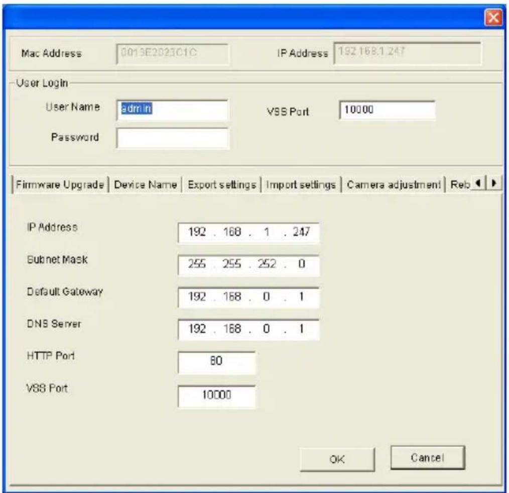
text_image
Mac Address 0013E2023C1C IP Address 192.168.1.247 User Login User Name admin VSS Port 10000 Password Firmware Upgrade Device Name Export settings Import settings Camera adjustment Reb IP Address 192 . 168 . 1 . 247 Subnet Mask 255 . 255 . 252 . 0 Default Gateway 192 . 168 . 0 . 1 DNS Server 192 . 168 . 0 . 1 HTTP Port 80 VSS Port 10000 OK CancelFigure 6-4
- Click the Firmware Upgrade tab. This dialog box appears.
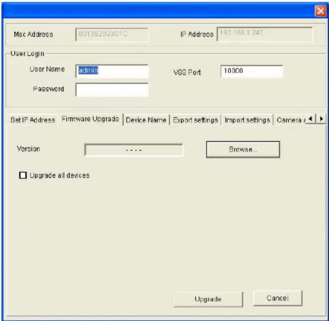
text_image
Mac Address 0013E2023C1C IP Address 192.168.1.247 User Login User Name admin VSS Port 10000 Password Set IP Address Firmware Upgrade Device Name Export settings Import settings Camera Version .... Browse... □ Upgrade all devices Upgrade CancelFigure 6-5
- Click the Browse button to locate the firmware file (.img) saved at your local computer.
- If you like to upgrade all the cameras in the list, select Upgrade all devices.
- Type Password, and click Upgrade to start the upgrade.
6.2 Backing Up and Restoring Settings
With the IP Device Utility included in the Software DVD, you can back up the configurations in the camera, and restore the backup data to the current camera or import it to another camera.
To back up the settings:
- Run IP Device Utility and locate the desired camera. See Steps 1-3 in 6.1.2 Using the IP Device Utility.
- Double-click the camera in the list. Figure 6-4 appears.
- Click the Export Settings button. This dialog box appears.
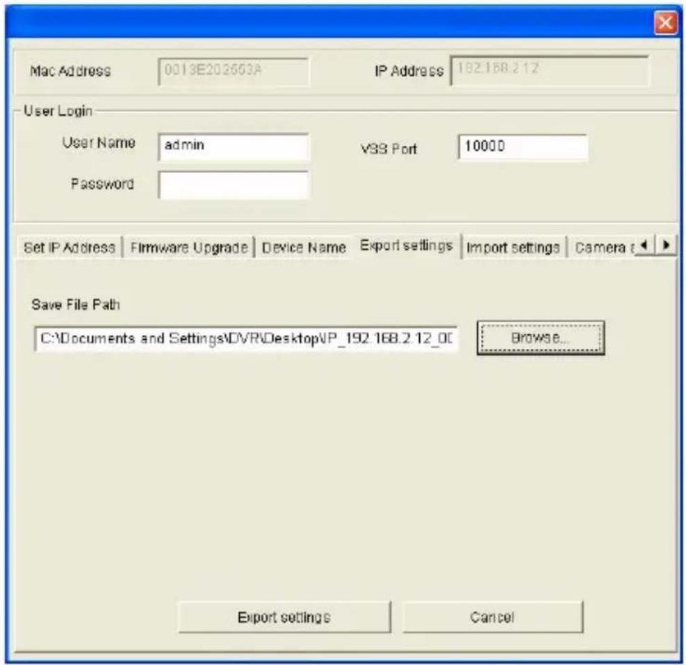
text_image
Mac Address 0013E202603A IP Address 192.168.2.12 User Login User Name admin VSS Port 10000 Password Set IP Address Firmware Upgrade Device Name Export settings Import settings Camera Save File Path C:\Documents and Settings\DVRS\Desktop\VP_192.168.2.12_0C Browse... Export settings CancelFigure 6-6
-
Click the Browse button to assign a file path.
-
Type Password, and click the Export settings button to save the backup file.
To restore the settings:
- In Figure 6-4, click the Import Settings tab. This dialog box appears.
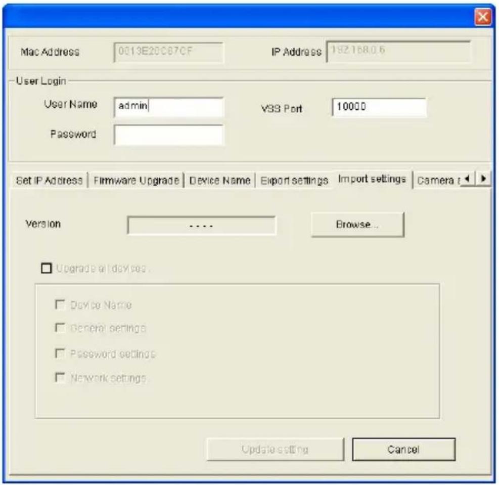
text_image
Mac Address 0013E20C87CF IP Address 192.168.0.6 User Login User Name admin vSS Port 10000 Password Set IP Address | Firmware Upgrade | Device Name | Export settings | Import settings | Camera | Version .... Browse... □ Upgrade at devices □ Device Name □ General settings □ Password settings □ Network settings Update setting CancelFigure 6-7
- Click the Browse button to locate the backup file (.dat).
- Select Upgrade all devices to import the settings into devices of the same type in the same LAN.
- To import device name, password settings and/or network settings, select Device Name, Password settings and/or Network settings.
- Type the Password and click the Update settings button to start restoring.
6.3 Changing Password
You change the login password of your GV-IP Camera using GV-IP Device Utility.
- Make sure you have installed and executed GV-IP Device Utility. For details, see steps 1 to 3 in 7.1.2 Using the GV-IP Device Utility. This page appears.
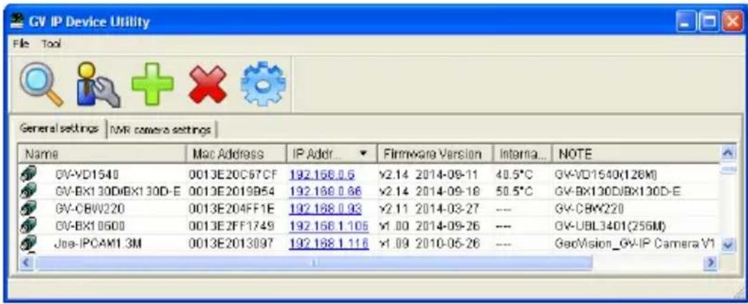
text_image
GV IP Device Utility File Tool General settings | NMR camera settings | Name Mac Address IP Addr... Firmware Version Internal... NOTE GV-VD1540 0013E20C67CF 192.168 0.5 ¥2.14 2014-09-11 40.5°C GV-VD1540(126M) GV-BX130D/BX130D-E 0013E2019B54 192.168 0.66 ¥2.14 2014-09-18 50.5°C GV-BX130D/BX130D-E GV-CBW220 0013E204FF1E 192.168 0.93 ¥2.11 2014-03-27 --- GV-CBW220 GV-BX1 0600 0013E2FF1749 192.168 1.105 ¥1.00 2014-09-26 --- GV-UBL3401(256M) Joe-IPOAM1.3M 0013E2013097 192.168 1.116 ¥1.09 2010-05-26 --- GedVision_GV-IP Camera V1Figure 6-8
- Double-click one camera in the list. This window appears.
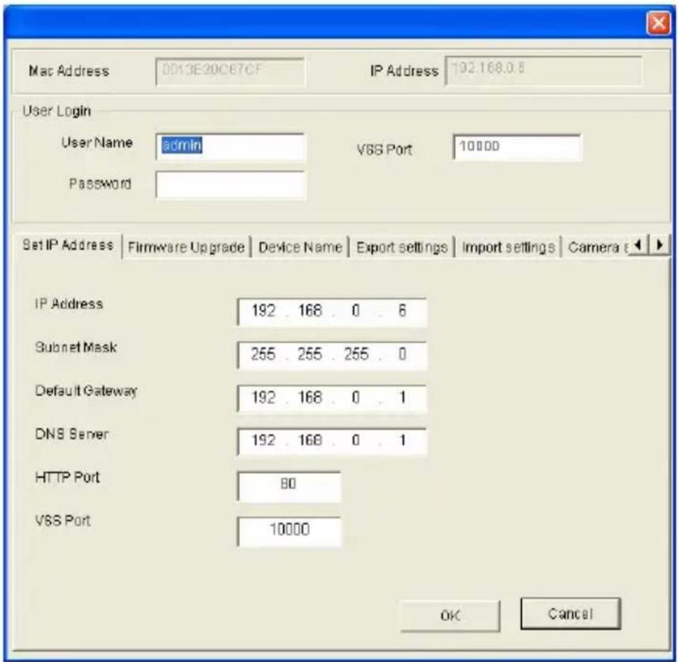
text_image
Mac Address 0013E20C67CF IP Address 192.168.0.6 User Login User Name admin VSS Port 10000 Password Set IP Address | Firmware Upgrade | Device Name | Export settings | Import settings | Camera | IP Address 192 . 168 . 0 . 6 Subnet Mask 255 . 255 . 255 . 0 Default Gateway 192 . 168 . 0 . 1 DNS Server 192 . 168 . 0 . 1 HTTP Port 80 VSS Port 10000 OK CancelFigure 6-9
- Type Password, click ▶, select Other Settings and then select Change Password. This dialog box appears.
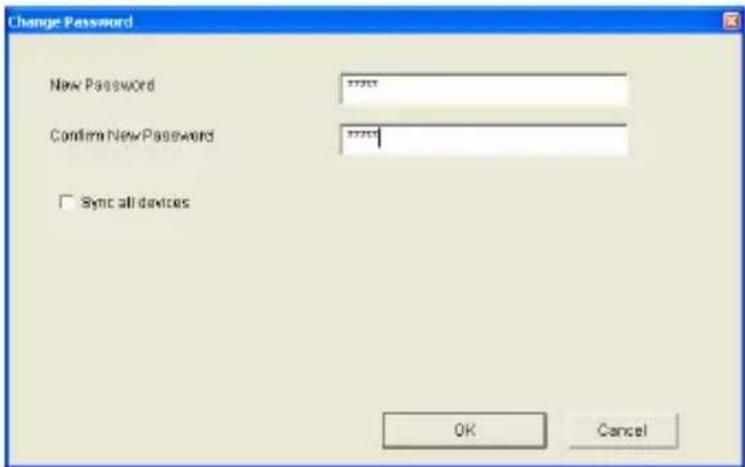
text_image
Change Password New Password Confirm New Password Sync all devices OK CancelFigure 6-10
GeoVision
- Type the new password in both fields. To change devices of the same type to the same password, select Sync all devices.
- Click OK to apply the change.
6.4 Verifying Watermark
The watermark is an encrypted and digital signature embedded in the video stream during the compression stage, protecting the video from the moment of creation. Watermarking ensures that an image is not edited or damaged after it is recorded. To enable the watermark function, see [Watermark Setting], 4.1.1 Video Settings.
The Watermark Proof is a watermark-checking program. It can verify the authenticity of the recording before you present it in court.
6.4.1 Accessing AVI Files
To verify watermark, first you have to access the recorded AVI files by one of these methods:
- Use the File Save function (No.6, Figure 3-3) to start recording on the local computer.
- Use the Act as FTP Server function to download AVI files from the camera. See 4.4.2 FTP.
- Use the files recorded on the memory card. Since the files saved on the memory card are of Linux file system, remember to run Ext2Fsd program for Windows-based system to read and access Linux-based files. For the instructions, see 5.2.1 Playback from the Memory Card.
6.4.2 Running Watermark Proof
- Install Watermark Proof from the Software DVD. After installation, a WMProof icon is created on your desktop.
- Double-click the created icon. The Water Mark Proof window appears.
- Click File from the menu bar, select Open and locate the recording (.avi). The selected recording is then listed on the window. Alternatively, you can drag the recording directly from the storage folder to the window.
- If the recording is unmodified, a check mark will appear in the Pass column. On the contrary, if the recording is modified or does not contain watermark during recording, a check mark would appear in the Failed column. To review the recording, double-click the listed file on the window.
6.4.3 The Watermark Proof Window
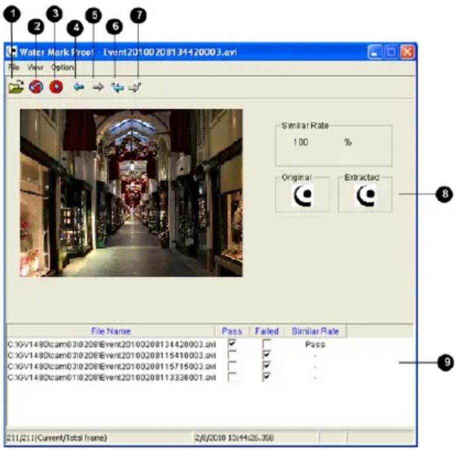
text_image
Water Mark Proof - Event20100208134420003.avi File View Option Similar Rate 100 % Original Extracted 8 File Name Pass Failed Similar Rate C:\GV1480\cam0310208\Event20100208134420003.avi ✓ Pass - C:\GV1480\cam0310208\Event20100208115410003.avi ✓ - C:\GV1480\cam0310208\Event20100208115715003.avi ✓ - C:\GV1480\cam0310208\Event20100208113336001.avi ✓ - - 9 211/211(Current/Total frame) 2/6/2010 13:44:25.358Figure 6-11
The controls in the window:
| No. | Name | Description | |
| 1 | Open File | Opens the recording. | |
| 2 | First Frame | Goes to the first frame of the file. | |
| 3 | Play | Plays the file. | |
| 4 | Previous Frame | Goes to the previous frame of the file. | |
| 5 | Next Frame | Goes to the next frame of the file. | |
| 6 | Previous WatermarkedFrame | Goes to the previous frame thatcontains watermark. | |
| 7 | Next | Watermarked | Goes to the next frame that containsFramewatermark. |
| 8 | Original | vs. | The Extracted icon should be identical with the Original icon. If not, itExtracted indicates the recording has been tampered. |
| 9 | File List | Displays the proof results. | |
6.5 Downloading Videos from the Micro SD Card
When connections of GV-IP Cameras to the GV-System are lost, recordings are automatically saved to the memory cards inserted in the GV-IP Cameras. To automatically synchronize and download recordings from the micro SD cards to a local folder, install and execute the GV-SDCardSync Utility program.
Note: GV-SDSyncCard Utility is only supported in GV-System V8.5.4 or later and in GV-IPCam H.264 V1.11 or later.
6.5.1 Installing the GV-SDCardSync Utility
- Download the GV-SD Card Sync Utility program from http://ftp.geovision.tw/FTP/neo/Utility/GvSDCardSync_Setup.zip
Note: The GV-SD Card Sync Utility must be installed on the computer installed with GV-System V8.5.4 or later.
- Execute the GV-SDCard Sync Utility program. The main window and the Setting window appear. The Setting window pops up automatically upon first execution. Otherwise, click the Setting button .
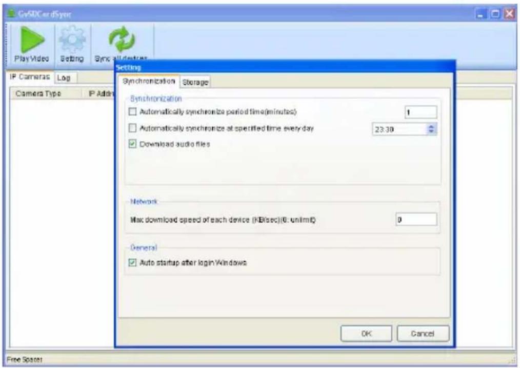
text_image
OpAIC card sync PlayVideo Setting Sync all devices IP Cameras Log Camera Type IP Address Setting Synchronization Storage Synchronization □ Automatically synchronize period time(minutes) 1 □ Automatically synchronize at specified time every day 23.30 ✓ Download audio files Network Max download speed of each device (KB/sec)(0: un/ml) 0 General ✓ Auto startup after login Windows OK Cancel Free SpaceFigure 6-12
- To configure synchronization, network and startup settings, see the steps below.
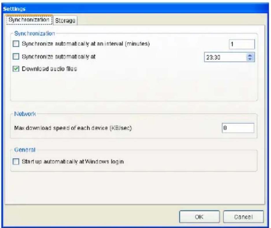
text_image
Settings Synchronization Storage Synchronization □ Synchronize automatically at an interval (minutes) 1 □ Synchronize automatically at 23:30 ✓ Download audio files Network Max download speed of each device (KB/sec) 0 General □ Start up automatically at Windows login OK CancelFigure 6-13
[Synchronization]
■ Synchronize automatically at an interval: Automatically synchronize videos from micro SD cards to a local folder at the specified interval.
■ Synchronize automatically at: Automatically synchronize videos from micro SD cards to a local folder at the specified time.
■ Download Audio Files: You may choose to download audio files along with the video files. This option is enabled by default.
[Network]
■ Max. download speed of each device (Kb/sec): To make sure the bandwidth is not completely taken up while downloading files from the memory card, specify a maximum download speed. If you do not want to set a bandwidth limit, type 0.
[General]
■ Start up automatically at Windows login: GV-SDSync Utility launches automatically when Windows starts up.
- By default, downloads are saved to :\GvSDCardSync and are not recycled automatically. To configure the storage and recycling settings, select the Storage tab on the Setting window. This page appears.
![Geovision GV-BX1500-3V - [General] - 1](/content/2026/05/785387/images/9b3715adeb4f0dffb7b8be2c1855aa3b72b8eb9e88aa92236001b7618330c4e8.jpg)
text_image
Settings Synchronization Storage Recycle □ Recycle when the storage space is less than (GB) 1 □ Keep the downloaded files for (Days) 1 Storage Location D:\GvSDCardSync OK CancelFigure 6-14
[Recycle]
■ Recycle when the storage space is less than (GB): Specify a minimum free space of your local storage for file recycling.
- Keep the downloaded files for (Days): Specify the number of days to keep the download files at the local hard drive.
[Storage Location]
To configure the storage path, click the button next to the location field and specify a storage location.
- Click OK to save the configuration or exit the Setting window.
Note: Keep the GV-SDCardSync Utility running in the background to automatically synchronize and download videos.
6.5.2 The GV-SDCardSync Utility Window
After you have installed the GV-SDCardSync Utility, point to Start, select Programs, select GV-SDCardSync and select GvSDCardSync to launch the program. This window appears.
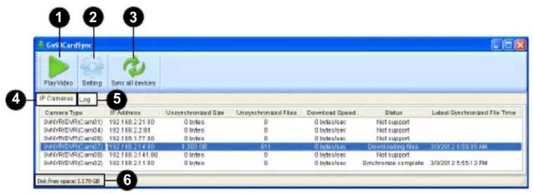
text_image
GVR CardSync Play Video Setting Sync all devices IP Cameras Log Camera Type IP Address Unsynchronized Size Unsynchronized Files Download Speed Status Latest Synchronized File Time GVR/RD/VR(Cam01) 192.188.2.21:30 0 bytes 0 0 bytes/sec Not support GVR/RD/VR(Cam04) 192.188.2.2.91 0 bytes 0 0 bytes/sec Not support GVR/RD/VR(Cam05) 192.188.1.77:30 0 bytes 0 0 bytes/sec Not support GVR/RD/VR(Cam07) 192.188.2.14:30 1.363 GB 611 0 bytes/sec Downloading file 3/3/2012 E:\$0.15 AM GVR/RD/VR(Cam09) 192.188.3.141:30 0 bytes 0 0 bytes/sec Not support GVR/RD/VR(Cam02) 192.188.2.11:30 0 bytes 0 0 bytes/sec Synchronize complete 3/3/2012 5:55:13 PM Disk free space: 1.176 GBFigure 6-15
| No. | Name | Description | |
| 1 | Play | Video | Plays downloaded recordings of the selected GV-IP Cameras using the ViewLog player. For details, see Chapter 4, DVR User's Manual on Surveillance System Software DVD. |
| 2 | Setting | Contains settings on synchronization, network, storage location and recycling criteria. See step 4 in 6.6.1 Installing the GV-SDCardSync Utility. | |
| 3 | Sync all devices | Manually synchronizes and downloads the recording files stored at GV-IP Cameras. | |
| 4 | IP Camera Tab | Shows information of GV-IP Cameras connected to the GV-System, including channel number, IP address, size and number of unsynchronized files, download speed, status and the last synchronization time. | |
| 5 | Log | Tab | Displays up to 100 event entries of the GV-SDCardSync Utility. Once the entries are full, recycling will start from the oldest file. |
| 6 | Storage | Space | Shows the storage space of the designated hard drive. |
Note:
-
The synchronization time is recorded according to the system time of the GV-IP Camera.
-
The logs are deleted once the GV-SDCardSync Utility is re-activated.
Chapter 7 DVR Configurations
The GV-System and GV-VMS provide a complete video management, such as video viewing, recording, playback, alert settings and almost every feature of the system. Note that GV-System version 8.5.5.0 or later or GV-VMS version 14.10 or later is required.
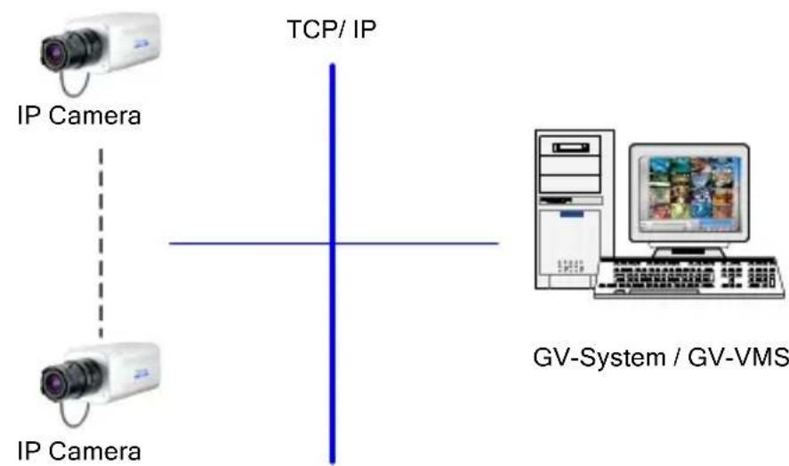
flowchart
graph TD
    A["IP Camera"] --> B["TCP/ IP"]
    C["IP Camera"] --> B
    B --> D["GV-System / GV-VMS"]
Figure 7-1
The compatible version of GV-System / GV-VMS for each camera model:
| Camera Models | Compatible version of GV-System / GV-VMS |
| Box Camera | GV-BX2400-1F ~ 2FGV-BX3400-5VGV-BX5300-6V |
| V8.5.5 or later/V14.10 or later | |
| GV-BX1500-3V | |
| V8.5.7 or later/V14.10 or later | |
| GV-BX1500-8FGV-BX3400-8FGV-BX5300-8F | |
| V8.5.8 or later/V14.10 or later | |
| GV-BX2500 Series | |
| V8.5.9 or later/V14.10 or later | |
| GVBX2600 | |
| V8.6.2 (with patch files)or later/V14.10.1 (with patchfiles) or later | |
| *Video Analysis only works with GV-VMS V15.10 |
| Camera Models | Compatible version of GV-System / GV-VMS | |
| Box Camera | GV-BX12201 | V8.6.2 (with patch files) or later / V14.10.1 (with patch files) or later |
| Ultra Box Camera | GV-UBX1301 Series GV-UBX2301 Series GV-UBX3301 Series | V8.5.6 or later / V14.10 or later |
| Target Box Camera | GV-EBX1100 Series GV-EBX2100 Series | V8.5.9 or later / V14.10 or later |
| Target Fixed Dome | GV-EFD2101 GV-EFD3101 | V8.6.2 (with patch files) or later / V14.10.1 (with patch files) or later |
| GV-EFD5101 | V8.6.2.0 (with patch files) or later / V15.10.1.0 or later | |
| IR Arctic Camera | GV-BX1500-E | V8.5.8 or later / V14.10 or later |
| GV-BX2400-E GV-BX3400-E GV-BX5300-E | V8.5.7 or later / V14.10 or later | |
| GV-BX2510-E GV-BX5310-E | V8.5.9 (with patch files) / V14.10 or laterCompatible version of GV-System / GV-VMS | |
| Camera Models | ||
| Mini Fixed Dome | GV-MFD1501 Series | V8.5.7 or later / V14.10 or later |
| GV-MFD2401 Series GV-MFD3401 Series GV-MFD5301 Series | V8.5.8 or later / V14.10 or later | |
| GV-MFD2501 Series | V8.5.9 or later / V14.10 or later | |
| Mini Fixed Rugged Dome | GV-MDR220 GV-MDR320 GV-MDR520 | V8.5 or later / V14.10 or later |
| GV-MDR1500 Series GV-MDR3400 Series GV-MDR5300 Series | V8.5.9 or later / V14.10 or later | |
| Target Mini Fixed Dome | GV-EFD1100 SeriesGV-EFD2100 Series | V8.5.9 or later/V14.10 or later |
| Target Mini Fixed Rugged Dome | GV-EDR1100 SeriesGV-EDR2100 Series | V8.5.9 or later/V14.10 or later |
| Bullet Camera | GV-BL2400GV-BL3400GV-BL1210GV-BL2410GV-BL3410GV-BL5310 | V8.5.6 or later/V14.10 or later |
| GV-BL3700GV-BL5700 | V15.10.1 (with patch files)or later | |
| *GV-BL3700 / 5700 do not support GV-System. | ||
| GV-BL1500 | V8.5.7 (with patch files) orlater / V14.10 or later | |
| GV-BL2500GV-BL2510-EGV-BL5310-E | V8.5.9 or later/V14.10 or later | |
| Ultra Bullet Camera | GV-UBL1211GV-UBL2411GV-UBL3411GV-UBL1301 SeriesGV-UBL2401 SeriesGV-UBL3401 Series | V8.5.6 or later / V14.10 or later |
| GV-UBL1511 | V8.5.8 or later / V14.10 or later | |
| GV-UBL2511 | V8.5.9 or later / V14.10 or later | |
| Target Bullet Camera | GV-EBL1100 SeriesGV-EBL2100 Series | V8.5.9 or later / V14.10 or later |
| GV-EBL2101 | V8.6.2.0 or later / V14.10.1 or later | |
| PTZ Camera GV-PTZ010D | V8.4 or later / V14.10 or later | |
| PT Camera | GV-PT130DGV-PT220DGV-PT320D | V8.5.7 or later / V14.10 or later |
| Target Vandal Proof IP Dome | GV-EVD2100GV-EVD3100 | V8.6.2 (with patch files) or later/V14.10.1 (with patch files) or later |
| GV-EVD5100 | V8.6.2.0 (with patch files) or later/V15.10.1.0 or later | |
| Vandal Proof IP Dome | GV-VD120D SeriesGV-VD220D SeriesGV-VD320D Series | V8.4 (with patch files) or later / V14.10 or later |
| GV-VD1500 | V8.5.8 or later/V14.10 or later | |
| GV-VD2400GV-VD3400 | V8.5.6 or later/V14.10 or later | |
| GV-VD1530/1540GV-VD2430/2440GV-VD2500/2530/2540GV-VD2540-EGV-VD3430/3440GV-VD5340GV-VD5340-E | V8.5.9 or later/V14.10 or later | |
| GV-VD3700GV-VD5700 | V15.10.1 (with patch files) or later | |
| *GV-VD3700 / 5700 do not support GV-System. | ||
| Camera Models | Compatible version of GV-System | |
| Fixed IP Dome | GV-FD3400 | V8.5.7 or later / V14.10 or later |
| GV-FD3410 | ||
| GV-FD1500 | V8.5.8 or later / V14.10 or later | |
| GV-FD1510 | ||
| GV-FD2500 | V8.5.9 or later / V14.10 or later | |
| GV-FD2510 | ||
| Cube Camera | GV-CB120 | V8.4.3 (with patch files) or later / V14.10 or later |
| GV-CB220 | ||
| Advanced Cube Camera | GV-CA120 | V8.5.5 or later / V14.10 or later |
| GV-CA220 | ||
| GV-CAW120 | ||
| GV-CAW220 | ||
| Pinhole Camera | GV-UNP2500 | V8.6.0 or later / V14.10.1 (with patch files) or later |
- The maximum number of streams which the camera allows varies according to its resolution:
| Camera Models Max. No. of Streams | |
| GV-PTZ010D | 3 |
| 1.3 M models except GV-PTZ010D 8 | |
| 2 M models | 6 |
| 3 M models | |
| 5 M models | |
| 8 M models | 8 |
| 12 M models |
- When the camera is connected to IE browser or any other applications, it takes up 1 stream; when the camera is connected to GV-System / GV-VMS, it takes up 2 streams.
Note: By default, the camera is in dual streams and will take up 2 streams when connected to GV-System / GV-VMS.
- The hardware compression and the "Pre-Recording Using RAM" feature cannot work on the videos from the camera.
7.1 Setting up an IP Camera on GV-System
To set up the camera on the GV-System, follow these steps:
Note: GV-System is not supported by the GV-IPCAM H.265 models (GV-VD3700 / 5700 and GV-BL3700 / 5700).
- On the main screen, click the Configure button, select System Configure, select Camera Install and click IP Camera Install. This dialog box appears.
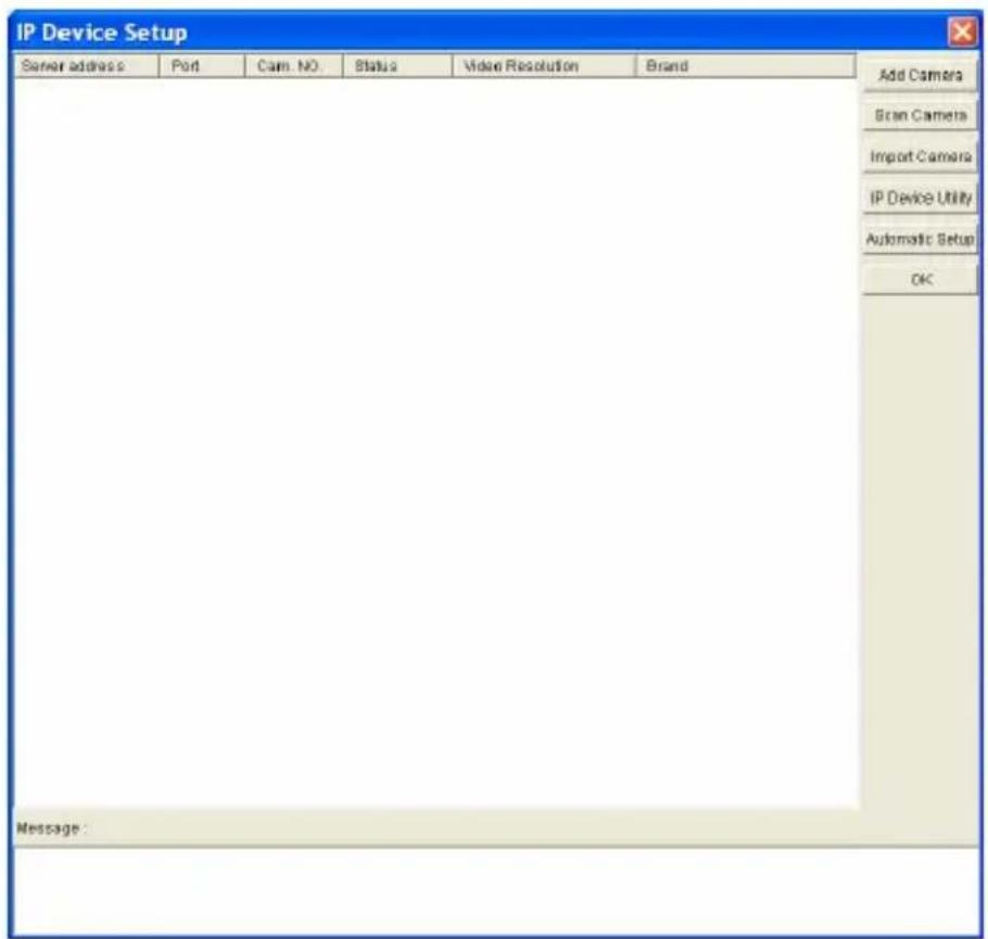
text_image
IP Device Setup Server address Port Cam. NO Status Video Resolution Brand Add Camera Scan Camera Import Camera IP Device Utility Automatic Setup OK Message:Figure 7-2
- To add an IP camera from a list of the IP cameras on the LAN, click Scan Camera.
-
To manually set up an IP camera, follow steps 2 to 7
-
Click Add Camera. The dialog box appears.
text_image
Select Brand Server IP : 192.168.1.245 HTTP Port : 80 User name : admin Password : ****** Brand : GeoVision Device : Please select the brand of IP camera Message : CloseFigure 7-3
- Type the IP address, username and password of the IP camera. Select the camera brand and device from the drop-down lists. This dialog box appears.
text_image
GV PTZ Camera (GV PTZ010) Query Dual Stream Query Cancel Status : Standby Camera list Select Port Port 10000 Stream Number Single Stream Dual Stream Codec Type Preview: MPEG4_ASP Record JPEG Resolution Record ApplyFigure 7-4
-
The GV-System will automatically query for the IP camera, and the status will be indicated as "Standby". If not, modify the HTTP port (Figure 7-3) and streaming port (Figure 7-4) to match those of the IP camera, and click the Query button to detect the IP camera again.
-
The options in the setup dialog box may vary depending on the camera model.
■ Dual Stream: Click this button to set the codec type to H.264 in the main stream and to MJPEG in the sub stream, and each stream with a different resolution. For details on supported versions and resolutions in different cameras, see Appendix F.
■ Port: Video streaming port number.
■ Stream Number: You have the option of single streaming only or both single and dual streaming.
■ Codec type: You have the options of JPEG and H.264. If the selected camera supports dual streaming, the preview codec and recording codec can be set differently.
■ Resolution: Select resolutions for preview and recording.
- Click Apply. The IP camera is added to the list.
- Click the listed camera, and select Display position to map the IP camera to a channel on the GV-System.
text_image
IP Device Setup Bener address Port Cam. NO. Status Video Resolution Brand 192.188.1.185 10000 No Disconnect Deploy position GV-BL1100_Ban... 192.188.1.231 10000 No Disconnect Delete camera GV-Smart Box(C... Change setting Change Resolution Remote camera setting Duplicate Camera Network Time Out On Demand Display Change live view codec Change record codec Frames to keep in live view buffer Record stream type GIS Setting Automatically adjust DST Add Camera Scan Camera Import Camera IP Device Utility Automatic Setup OKFigure 7-5
- The Status column now should display "Connected". Click OK.
7.1.1 Customizing IP Camera Settings on GV-System
After the IP camera is connected and assigned with a display position, you can configure the camera's settings such as frame rate, codec type and resolution. Right-click the desired camera to see the following list of options:
text_image
IP Device Setup Server address Port Cam. NO. Status Video Resolution Brand 192.168.2.12 10000 Cameroon Connected 192.168.2.12 Compression_GV-VD220D_Ben Disconnect camera Change position Delete camera Change Resolution Remote camera setting Network Time Out Change Codec Live view frame rate control (Sub stream) Image Orientation Frames to keep in live view buffer Recording codec format GIS Setting Automatically adjust DST Add Camera Scan Camera Import Camera IP Device Utility Automatic Setup OKFigure 7-6
■ Change Resolution: Changes the display ratio, live view resolution and record resolution
■ Network Time Out: When network disconnection exceeds the specified time period, the camera status will be displayed as Connection Lost.
■ Change Live View Codec: Changes the live view codec.
■ Change Record Codec: Changes the recording codec.
■ Live-view frame rate control (Sub stream): Sets the live view frame rate of the sub stream to help reduce the CPU usage. If you have set the live view codec to be JPEG, select the number of frames to allow in a second. If you chose the H.264 codec, select one of the following options:
Maximum Live-view Frame Rate: View the video at the maximum frame rate possible.
Live-view Key Frame only: You can choose to view the key frames of the videos only instead of all frames on the live view. This option is related to the GOP setting of the IP camera. For example, if the GOP value is set to 30, there is only one key frame among 30 frames.
■ Live-view frame rate control (Main stream): Sets the live view frame rate of the main stream with higher resolution when On Demand function is enabled. Refer to Live-view frame rate control above to see the options available.
■ Image Orientation: You can adjust the image orientation by selecting Normal, Horizontal Mirror, Vertical Flip or Rotate 180.
■ Frames to keep in live view buffer: Specifies the number of frames to keep in the live view buffer.
■ Recording Codec Format: Specifies whether to record in standard or GeoVision type of JPEG or H.264 codec.
GIS Setting: Records the video with the GPS data. To record the GPS data, remember to also enable the GIS function of the GV-System (Configure button < Accessories < Enable Local GIS).
■ Automatically Adjust DST: If enabled, the time on the GV-IP device Web interface will be synchronized with the time of the GV-System when DST period starts or ends on the GV-System.
7.2 Setting Up IP Cameras on GV-VMS
Follow the steps below to manually connect your GV-IP Camera to GV-VMS.
Note: The following instructions are based on V14.10 software and user interfaces.
- To access the IP Device Setup page, click Home 🔒, select Toolbar

, click Configure and select Camera Install.

select Toolbar
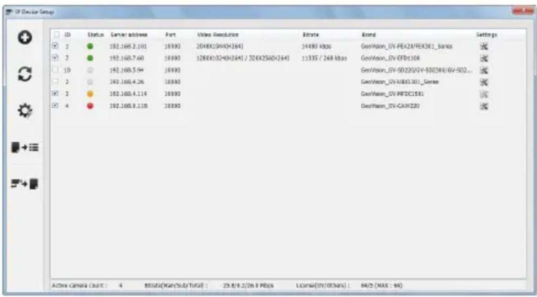
text_image
ID Status Server address Port Video Resolution Bitrate Stand Settings 1 2 3 4 10 11 12 13 14 15 16 17 18 19 20 21 22 23 24 25 26 27 28 29 30 31 32 33 34 35 36 37 38 39 40 41 42 43 44 45 46 47 48 49 50 51 52 53 54 55 56 57 58 59 60 61 62 63 64 65 66 67 68 69 70 71 72 73 74 75 76 77 78 79 80 81 82 83 84 85 86 87 88 89 90 91 92 93 94 95 96 97 98 99 100Figure 7-7
- Click Add Camera ☐. This dialog box appears.
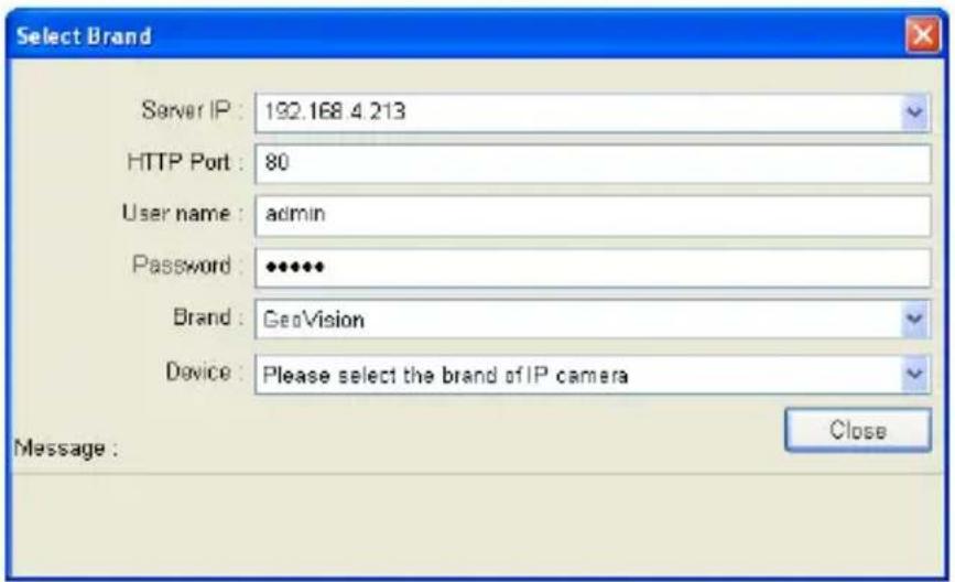
text_image
Select Brand Server IP: 192.168.4.213 HTTP Port: 80 User name: admin Password: •••••• Brand: GeoVision Device: Please select the brand of IP camera Message: CloseFigure 7-8
- Type the IP address, username and password of the GV-IP Camera. Modify the default HTTP port 80 if necessary.
- Select GeoVision and model name from the Brand drop-down list and select the GV-IP Camera from the Device drop-down lists. This dialog box appears.
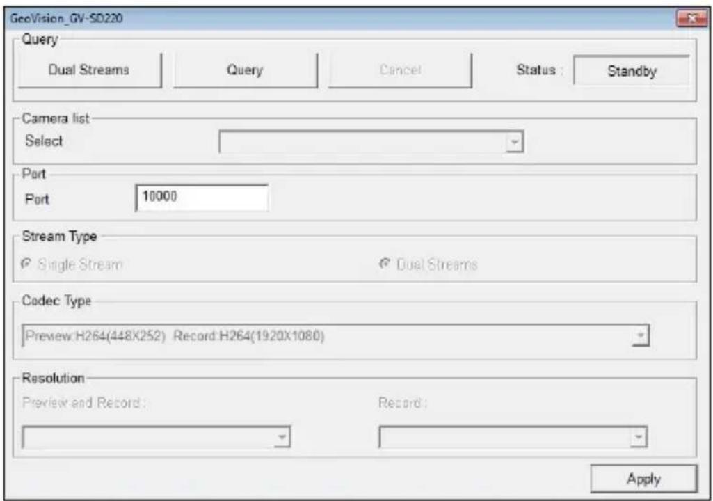
text_image
GeoVision_GV-SD220 Query Dual Streams Query Cancel Status: Standby Camera list Select Port Port 10000 Stream Type Single Stream Dual Streams Codec Type Preview:H264(448X252) Record:H264(1920X1080) Resolution Preview and Record: Record: ApplyFigure 7-9
- In the dialog box, configure the options which may vary depending on camera brands.
■ Dual Streams: It is set to dual streams by default. Select this option to apply the dual-streaming settings (lower resolution for live view and higher resolution for recording) if the camera supports dual streams.
■ Query: Detect and apply the current codec and resolution setting on the camera. This function may not be available for some third-party cameras.
■ Camera list: Select a camera number.
■ Port: Modify the video streaming port number if necessary.
■ Stream Type: You may have the option of Single Stream or Dual Streams depending on camera models.
■ Codec Type: You may have different codec options depending on camera models. If the selected camera supports dual streaming, the live view codec and recording codec can be set differently.
■ Resolution: You may select the different resolutions for live view and recording.
- Click Apply to add the GV-IP Camera to the list.
- To connect the added camera, click the box besides the ID column. Upon successful connection, the Status icon shows green, with the video resolution and bit rate being displayed in the correspondent columns.

text_image
ID Status Server address Port Video Resolution Bitrate Brand Settings 1 192.168.7.51 10000 1920X10B0(H264) / 448X252(H264) 10210 / 483 kbps GeoVision_GV-SD220/GV-SD2300...Figure 7-10
7.3 Remote Monitoring with Multi View
You can use the Multi View to monitor and manage the camera.
Note: Multi View is not supported by GV-VMS.
7.3.1 Connecting to the IP Camera
- On the Multi View window, click the Edit Host button. The Edit Host window appears.
- To create a host, click the New button. You need to create a group before creating a host.
- Select GV-IP Camera, GV-IP Speed Dome from the Device drop-down list. Type the host name, IP address, user name and password of the camera. Modify the default VSS port 10000 if necessary.
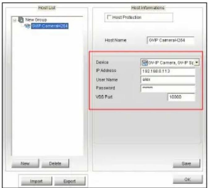
text_image
Host List New Group GVP CameraH264 Host Informations Host Protection Host Name GVP CameraH264 Device GVP-IP Camera, GVP-IP Sp IP Address 192.168.0.113 User Name alias Password ****** VSS Port 10.000 Import Delete Save OKFigure 7-11
- Click Save to establish connection.
For details on the Multi View functions, see "Multi View Viewer", Remote Viewing, DVR User's Manual on the Surveillance System Software DVD.
7.4 Remote Monitoring with E-Map
You can use the Remote E-Map to monitor and manage the camera.
7.4.1 Creating an E-Map for the IP Camera
With the E-Map Editor, you can create an E-Map for the camera. The E-Map Editor is available in the two applications: Main System and E-Map Server. The following is an example of running the E-Map Editor included in the Main System.
- Go to Windows Start menu, point to Programs, select GV folder and click E-Map Editor.
- To create an E-Map, click the Add Map button on the toolbar. A New Map file appears.
- Double-click the New Map file, and click the Load Map button on the toolbar to import a graphic file
- To create a host, click the Add Host button on the toolbar and select Add IPCam.
- Right-click the created New Host in the Host View, and select Host Settings. This dialog box appears.
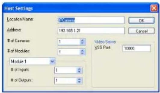
text_image
Host Settings Location Name: PCnet Address: 192.168.1.21of Cameras: 1
of Modules: 1
Module 1of Inputs: 1
of Outputs: 1
OK Cancel Video Server USS Part 10000Figure 7-12
- Give the camera a location name, and type its IP address (or domain name). Modify the default VSS port 10000 if necessary.
GeoVision
- Click OK to save the settings.
- Expand the created host folder. Drag and drop the icons of camera and I/O devices onto the imported E-Map.
- Close the E-Map Editor. Click Yes when you are promoted to save the file.
For details on creating an E-Map file on the E-Map Server, see "E-Map Applications", GV-DVR User's Manual or GV-VMS User's Manual on the Surveillance System Software DVD.
7.4.2 Connecting to the IP Camera
Depending on where you save the created E-Map file (DVR, E-Map Server or Control Center), the steps to open the Remote E-Map window for monitoring may vary slightly. The following is the connection example when you store the E-Map file on the DVR.
- To enable the remote access to the DVR, click the Network button, select WebCam Server to display the Server Setup dialog box, and click OK to start the WebCam Server.
- At the local computer, open the web browser and type the address of the DVR. The Single View page appears.
- Select Emap. A valid user name and password are required for login. For the first-time user, you will be directed to the Download page. Install the E-Map program before you can run it.
- On the Remote E-Map window, click the Login button and select the camera host to access its videos and I/O devices. A valid user name and password are required to log in the camera.
For details on the Remote E-Map functions, see "E-Map Applications", GV-DVR User's Manual or GV-VMS User's Manual on the Surveillance System Software DVD.
Chapter 8 CMS Configurations
This section introduces the related settings to enable connecting to the camera in the central monitoring stations Center V2, Vital Sign Monitor and Dispatch Server.
8.1 Center V2
The Center V2 can monitor and manage the camera and I/O devices connected to the camera.
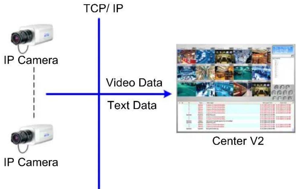
flowchart
graph TD
    A["IP Camera"] -->|IP Camera| B["TCP/IP"]
    C["IP Camera"] -->|IP Camera| B["TCP/IP"]
    D["Video Data"] --> E["Center V2"]
    F["Text Data"] --> E["Center V2"]
Figure 8-1
- To set the appropriate port for IP camera connection, click the Preference Settings button, select System Configure, click the Network tab, and select Accept connections from GV-Compact DVR, Video Server & IP Cam. Keep default port 5551, or modify it to match the Center V2 port on the IP camera.
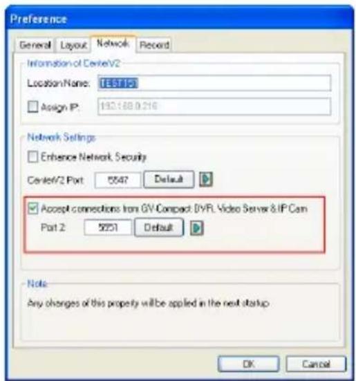
text_image
Preference General Layout Network Record Information of CentreV2 LocationName: TE5T10 Assign IP: 192.168.0.216 Network Settings Enhance Network Security CentreV2 Port 5547 Default Accept connections from GV Compact DVPL Video Server & IP Cam Part 2 5051 Default Note: Any changes of this property will be applied in the next startup OK CancelFigure 8-2
- To define how to display the received video on motion detection and input trigger from the IP camera, click the Preference Settings button and select System Configure. This dialog box appears.
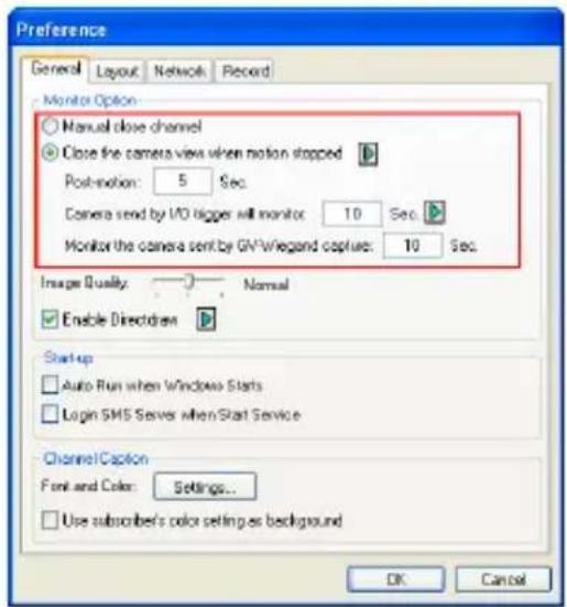
text_image
Preference General Layout Network Record Monitor Option Manual close channel Close the camera view when motion stopped Post-motion: 5 Sec. Camera send by I/O bigger will monitor 10 Sec. Monitor the camera send by GN-Wegand capture: 10 Sec. Image Quality: Normal Enable Directset Start-up Auto Run when Windows Starts Login SMS Server when Start Service Channel Caption Font and Color: Settings... Use subscriber's color setting as background OK CancelFigure 8-3
■ Manual close channel: Closes the triggered camera view manually.
■ Close the camera view when motion stopped: Closes the triggered camera view automatically when motion stops.
■ Post Motion: Specify the duration of the camera view remaining on the monitoring window after a motion stops.
■ Camera send by I/O trigger will monitor: Specify the duration of the camera view remaining on the monitoring window when an I/O device is triggered.
To keep the camera view remaining on the monitoring window even after the alarm is finished, click the right-arrow button, and uncheck Latch Trigger. Then the camera view will remain on the monitoring window for the specified time. For example, if the alarm is triggered for 5 minutes and you set 10 minutes, the camera view will be displayed for 15 minutes.
For further information on how to mange the video received from the IP camera, see GV-CMS Series User's Manual on the Surveillance System Software DVD.
8.2 Vital Sign Monitor
The Vital Sign Monitor is designed to monitor and manage the camera and I/O devices connected to the camera under low bandwidth network.
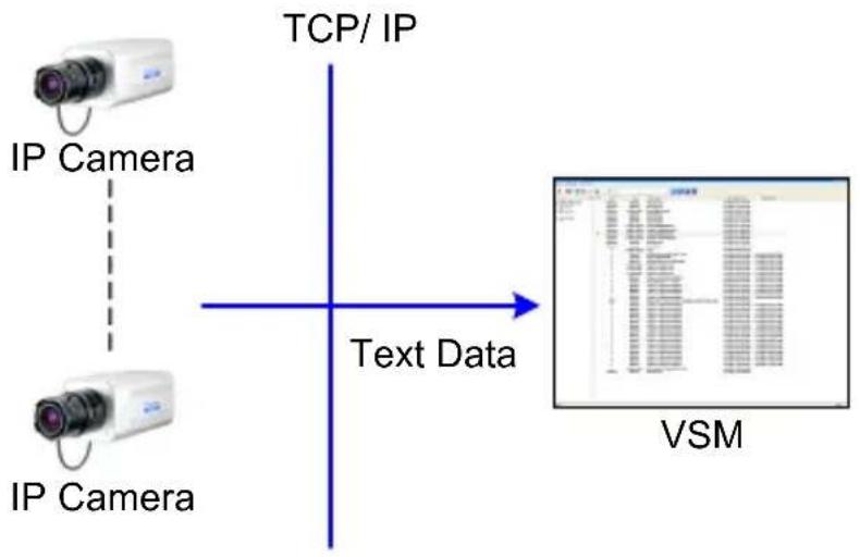
flowchart
graph TD
    A["IP Camera"] -->|TCP/IP| B["Text Data"]
    C["IP Camera"] -->|TCP/IP| B["Text Data"]
    B --> D["VSM"]
Figure 8-4
- To set the appropriate port connecting to the IP camera, click Configure on the window menu, and select System Configure to display this dialog box. In the Connective Port field, keep the default port 5609, or modify it to match the Vital Sign Monitor port on the IP camera.
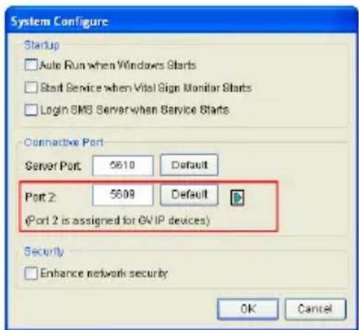
text_image
System Configure Startup □ Auto Run when Windows Starts □ Start Service when Vital Sign Monitor Starts □ Login SMS Server when Service Starts Connective Port Server Port 5610 Default Port 2: 5609 Default (Port 2 is assigned for OV IP devices) Security □ Enhance network security OK CancelFigure 8-5
For further information on how to mange the video received from the IP camera, see GV-CMS Series User's Manual.
8.3 Dispatch Server
The Dispatch Server minimizes overloading of Center V2 Servers by re-distributing the GV-IPCAM subscribers to the least busy Center V2 Server.
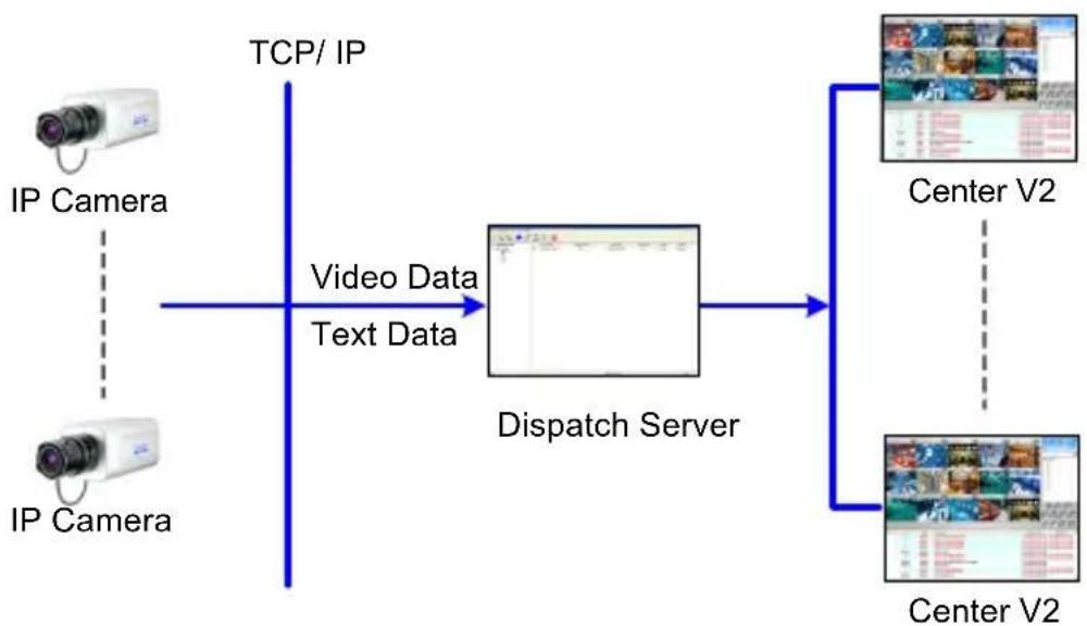
flowchart
graph LR
    A["IP Camera"] -->|TCP/IP| B["Dispatch Server"]
    C["IP Camera"] -->|Video Data Text Data| B
    B --> D["Center V2"]
    B --> E["Center V2"]
Figure 8-6
- To set the appropriate port connecting to the IP camera, click the Server Setting button on the toolbar, and select Allow GV IP devices to login as subscriber from port. Keep the default port as 5551, or modify it to match the Center V2 port on the IP camera.
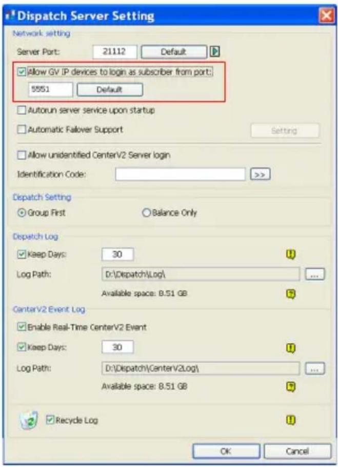
text_image
Dispatch Server Setting Network setting Server Port: 21112 Default Allow GV IP devices to login as subscriber from port: 5551 Default Autorun server service upon startup Automatic falover Support Setting Allow unidentified CenterV2 Server login Identification Code: >> Dispatch Setting Group First Balance Only Dispatch Log Keep Days: 30 Log Path: D:\Dispatch\Log\ Available space: 8.51 GB CenterV2 Event Log Enable Real-Time CenterV2 Event Keep Days: 30 Log Path: D:\Dispatch\CenterV2Log\ Available space: 8.51 GB Recycle Log OK CancelFigure 8-7
For further information on how to mange the video received from the IP camera, see GV-CMS Series User's Manual on the Surveillance System Software DVD
Chapter 9 Smart Device Connection
You can access the live view and play back recordings on your mobile devices using the mobile application GV-Eye. Android Smartphone, tablet, iPad, iPhone and iPod Touch are supported.
For details on system requirements, installation and setup, visit our website: http://www.geovision.com.tw/english/5_4_iview.asp
Note:
-
To receive the live video from the camera, enter the TCP/IP port on your mobile phone. To play video back, enable ViewLog Server on the camera and enter the RPB Port on your mobile phone.
-
To use the GV-Eye for the GV-IPCAM H.265 models, change the video codec setting to H.264.
Appendix
A. Settings for Internet Explorer 8
If you use Internet Explorer 8, it is required to complete the following setting.
- Set the Security to Medium-high (default).
- Enable Allow previously unused ActiveX controls to run without prompt.
- Disable Only allow approved domains to use ActiveX without prompt.
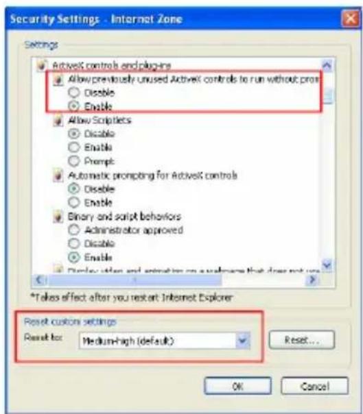
text_image
Security Settings - Internet Zone Settings ActiveX controls and plugins Allow previously unused ActiveX controls to run without pro Disable Enable Allow Scriptlets Disable Enable Prompt Automatic prompting for ActiveX controls Disable Enable Binary and script behaviors Administrator approved Disable Enable Display action and animation on a software that does not use *Takes effect after you restart Internet Explorer Reset custom settings Reset for: Medium-high (default) Reset... OK Cancel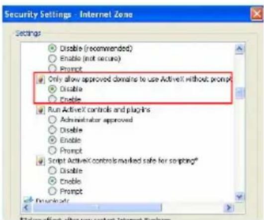
text_image
Security Settings - Internet Zone Settings Disable (recommended) Enable (not secure) Prompt Only allow approved domains to use ActiveX without prompt Disable Enable Run ActiveX controls and plugins Administrator approved Disable Enable Prompt Script ActiveX controls marked safe for scripting* Disable Enable Prompt DownloadB. Resolution and Frame Rate
Note that the frame rate and the performance may vary depending on the number of connections and data bitrates (different scenes).
| GV-IP Camera Stream Ratio Resolution | Max. Frame Rate | |||
| GV-BL1210GV-BL1500GV-BL1510GV-BX1200 SeriesGV-BX1500 SeriesGV-BX1500-EGV-CA120GV-CAW120GV-CB120GV-FD1200GV-FD1210GV-FD1500GV-FD1510GV-MDR1500 SeriesGV-MFD1501 SeriesGV-PT130D | Main | 4:3 1280 x 960 | 30 fps | |
| 16:9 1280 x 720 | ||||
| 5:4 1280 x 1024 | ||||
| Sub | 4:3 | 640 x 480320 x 240 | ||
| 16:9 | 640 x 360448 x 252 | |||
| 5:4 | 640 x 512320 x 256 | |||
| GV-UBL1301 Series GV-UBL1511 GV-UBX1301 Series GV-VD120D GV-VD121D GV-VD122D GV-VD123D GV-VD1500 GV-VD1530 GV-VD1540 | Main | 4:3 1280 x 960 | 30 fps | |
| 16:9 1280 x 720 | ||||
| 5:4 1280 x 1024 | ||||
| Sub | 4:3 | 640 x 480 320 x 240 | ||
| 16:9 | 640 x 360 448 x 252 | |||
| 5:4 | 640 x 512 320 x 256 | |||
| GV-EBL1100 Series GV-EBX1100 Series GV-EFD1100 Series GV-EDR1100 Series | Main | 4:3 | 1280 x 960 640 x 480 448 x 336 | 30 fps |
| 16:9 | 1280 x 720 640 x 360 448 x 252 | |||
| 5:4 | 1280 x 1024 640 x 512 448 x 360 | |||
| Sub | 4:3 | 640 x 480 448 x 336 | ||
| 16:9 | 640 x 360 448 x 252 | |||
| 5:4 | 640 x 512 448 x 360 | |||
| GV-BL2400 | Main | 4:3 | 1600 x 1200 | 30 fps |
| GV-BL2410 | 1280 x 960 | |||
| GV-BL2500 | 16:9 | 1920 x 1080 | ||
| GV-BL2510 | 1280 x 720 | |||
| GV-BL2510-E | 5:4 | 1280 x 1024 | ||
| GV-BX2400 Series | ||||
| GV-BX2500 Series | Sub | 4:3 | 640 x 480 | |
| GV-BX2600 * | 320 x 240 | |||
| GV-BX2400-E | 16:9 | 640 x 360 | ||
| GV-CA220 | 448 x 252 | |||
| GV-CAW220 | 5:4 | 640 x 512 | ||
| GV-CB220 | 320 x 256 | |||
| GV-FD2400 | ||||
| GV-FD2410 | ||||
| GV-FD2500 | ||||
| GV-FD2510 | ||||
| GV-MDR220 | ||||
| GV-MFD2401 Series | ||||
| GV-MFD2501 Series | ||||
| GV-PT220D | ||||
| GV-UBL2411 | ||||
| GV-UBL2511 | ||||
| GV-UBL2401 Series | ||||
| GV-UBX2301 Series | ||||
| GV-VD220D | ||||
*GV-BX2600 has a resolution of 448 x 256 (16:9).
*GV-BX2600 can reach the max. frame rate of 60 fps but Sub stream will be closed.
| GV-IP Camera Stream | Ratio Resolution | Max. Frame Rate | ||
| GV-EBL2100 Series* GV-EBX2100 Series* GV-EFD2100 Series* GV-EDR2100 Series GV-EFD2101 GV-EVD2100 | Main | 4:3 | 1280 x 960 640 x 480 320 x 240 | 30 fps / 25 fps* |
| 16:9 | 1920 x 1080 1280 x 720 640 x 360 448 x 252 | |||
| 5:4 | 1280 x 1024 640 x 512 320 x 256 | |||
| Sub | 4:3 | 640 x 480 320 x 240 | ||
| 16:9 | 640 x 360 448 x 252 | |||
| 5:4 | 640 x 512 320 x 256 | |||
| GV-EBL2101 | Main | 4:3 | 1280 x 960 640 x 480 | 30 fps |
| 16:9 | 1920 x 1080 1280 x 720 | |||
| 5:4 | 1280 x 1024 640 x 512 | |||
| Sub | 4:3 | 640 x 480 320 x 240 | ||
| 16:9 | 640 x 360 | |||
| 5:4 | 640 x 512 320 x 256 | |||
*The max. frame rate specifically for GV-EBL2100 Series, GV-EBX2100 Series, and GV-EFD2100 Series is 25 fps.
| GV-IP Camera | Stream | Ratio | Resolution | Max. Frame Rate |
| GV-EFD3101GV-EVD3100 | Main | 4:3 | 2048 x 15361600 x 12001280 x 960640 x 480320 x 240 | 30 fps |
| 16:9 | 1920 x 10801280 x 720640 x 360448 x 252 | |||
| 5:4 | 1280 x 1024640 x 512320 x 256 | |||
| Sub | 4:3 | 960 x 720 25 fps | ||
| 640 x 480320 x 240 | 30 fps | |||
| 16:9 | 640 x 360448 x 252 | |||
| 5:4 | 640 x 512320 x 256 | |||
| GV-EFD5101GV-EVD5100 | Main | 4:3 | 2592 x 19442048 x 15361600 x 12001280 x 960640 x 480320 x 240 | 30 fps |
| 16:9 | 1920 x 10801280 x 720640 x 360448 x 252 | |||
| 5:4 | 1280 x 1024640 x 512320 x 256 | |||
| Sub | 4:3 | 960 x 720 25 fps | ||
| 640 x 480320 x 240 | 30 fps | |||
| 16:9 | 640 x 360448 x 252 | |||
| 5:4 | 640 x 512320 x 256 | |||
| GV-IP Camera Stream Ratio Resolution | Max. Frame Rate | |||
| GV-BX12201 | Main | 4:3 | 4000 x 3000 15 fps | |
| 2560 x 19202048 x 15361600 x 12001280 x 960 | 30 fps | |||
| 16.9 | 3840 x 21601920 x 10801280 x 720 | |||
| 5:4 | 1280 x 1024 | |||
| Sub | 4:3 | 1024 x 768640 x 480320 x 240 | ||
| 16.9 | 1280 x 720640 x 360448 x 256 | |||
| 5:4 | 1280 x 1024640 x 512320 x 256 | |||
| GV-BL3400 | Main | 4:3 | 2048 x 1536 20 fps | |
| GV-BL3410 | 1600 x 1200 | 30 fps | ||
| GV-BX3400 Series | 1280 x 960 | |||
| GV-BX3400-E | 16:9 | 1920 x 1080 | ||
| GV-FD3400 | 1280 x 720 | |||
| GV-FD3410* | ||||
| GV-MDR320 | Sub | 5:4 1280 x 1024 | ||
| GV-MDR3400 Series | 4:3 | 640 x 480 | ||
| GV-MFD3401 Series | 320 x 240 | |||
| GV-PT320D | 16:9 | 640 x 360 | ||
| GV-UBL3411 | 448 x 252 | |||
| GV-UBL3401 Series | ||||
| GV-UBX3301 Series | ||||
| GV-VD320D | ||||
| GV-VD321D | ||||
| GV-VD322D | ||||
| GV-VD323D | ||||
| GV-VD3400* | ||||
| GV-VD3430 | ||||
| GV-VD3440 | ||||
| GV-IP Camera Stream Ratio Resolution | Max. Frame Rate | ||||
| GV-BL5310GV-BL5310-EGV-BX5300 SeriesGV-BX5300-EGV-MDR520GV-MDR5300 SeriesGV-MFD5301 SeriesGV-VD5340GV-VD5340-E | Main | 4:3 | 2560 x 1920 10 fps | 30 fps | |
| 2048 x 1536 20 fps | |||||
| 1600 x 12001280 x 960 | |||||
| 16:9 | 1920 x 10801280 x 720 | ||||
| 5:4 1280 x 1024 | |||||
| Sub | 4:3 | 640 x 480320 x 240 | |||
| 16:9 | 640 x 360448 x 252 | ||||
| 5:4 | 640 x 512320 x 256 | ||||
| GV-PTZ010D | Main | n/a | NTSC | 704 x 480704 x 240352 x 240 | 30 fps |
| PAL | 704 x 576704 x 288352 x 288 | 25 fps | |||
| Sub n/a | NTSC | 704 x 480704 x 240352 x 240 | 30 fps | ||
| PAL | 704 x 576704 x 288352 x 288 | 25 fps | |||
| GV-IP Camera | Stream | Ratio | Resolution | Max. Frame Rate |
| GV-UNP2500 | Main | 4:3 | 1600 x 12001280 x 960 | 30 fps |
| 16:9 | 1920 x 10801280 x 720 | |||
| 5:4 1280 x 1024 | ||||
| Sub | 4:3 | 640 x 480320 x 240 | ||
| 16:9 | 640 x 360448 x 252 | |||
| 5:4 | 640 x 512320 x 256 | |||
| GV-IP Camera | Stream | Ratio | Resolution | Max. Frame Rate |
| GV-VD3700GV-BL3700 | Main | 4:3 | 2048 x 15361600 x 12001280 x 960640 x 480 | 30 fps |
| 16:9 | 1920 x 10801280 x 720640 x 360 | |||
| 5:4 | 1280 x 1024640 x 512 | |||
| Sub | 4:3 | 640 x 480320 x 240 | ||
| 16:9 | 640 x 360448 x 252 | |||
| 5:4 | 640 x 512320 x 256 | |||
| GV-VD5700GV-BL5700 | Main | 4:3 | 2592 x 19442048 x 15361600 x 12001280 x 960640 x 480 | 30 fps |
| 16:9 | 2592 x 15202304 x 12961920 x 10801280 x 720640 x 360 | |||
| 5:4 | 1280 x 1024640 x 512 | |||
| Sub | 4:3 | 640 x 480320 x 240 | ||
| 16:9 | 640 x 360448 x 256 | |||
| 5:4 | 640 x 512320 x 256 |
C. Support Lists
- Support List for GV-Backup Center, GV-Video Gateway and GV-Recording Server
| GV-IP Camera Model Supported Version | ||
| Box Camera | GV-BX2400 SeriesGV-BX3400 SeriesGV-BX5300 Series | V1.15 or later |
| GV-BX12201 V1.12 or later for GV-Backup Center / V1.2.6.0 or later for GV-Video Gateway and GV-Recording Server | ||
| Mini Fixed Rugged Dome | GV-MDR220GV-MDR320GV-MDR520 | V1.07 or later |
| GV-IP Camera Model | Supported Version | |
| PTZ Camera GV-PTZ010D V1.08 | or later | |
| Vandal Proof IP Dome | GV-VD120D Series | V1.03 or later |
| GV-VD220D Series | ||
| GV-VD320D Series | ||
| *Vandal Proof IP Dome (H.265) | GV-VD3700 | V1.12 or later for GV-Backup Center |
| GV-VD5700 | ||
| Cube Camera | GV-CB120GV-CB220 | V1.03 or later |
| Advanced Cube Camera | GV-CA120GV-CA220GV-CAW120GV-CAW220 | V1.15 or later |
| Pinhole Camera GV-UNP2500 | V1.12 or later for GV-Backup Center / V1.26 or later for GV-Video Gateway and GV-Recording Server | |
* Vandal Proof IP Dome (H.265) does not support GV-Video Gateway and GV-Recording Server. To play the files backed up in GV-Backup Center, Remote ViewLog version 15.10 is required.
• Support List for Transmit Audio
| GV-IP Camera Model Supported Version | ||
| Box Camera | GV-BX1200 SeriesGV-BX2400 SeriesGV-BX3400 SeriesGV-BX5300 Series | V1.15 or later |
| Mini Fixed Rugged Dome | GV-MDR220GV-MDR320GV-MDR520 | V1.07 or later |
| PTZ Camera GV-PTZ010D V1.08 | or later | |
| Vandal Proof IP Dome | GV-VD120D Series | V1.05 or later |
| GV-VD220D Series | ||
| GV-VD320D Series | ||
| Cube Camera | GV-CB120GV-CB220 | V1.03 or later |
| Advanced Cube Camera | GV-CA120GV-CA220GV-CAW120GV-CAW220 | V1.15 or later |
• Support List for System Log
| GV-IP Camera Model Supported Version | ||
| Box Camera | GV-BX1200 SeriesGV-BX2400 SeriesGV-BX3400 SeriesGV-BX5300 Series | V1.15 or later |
| Mini Fixed Rugged Dome | GV-MDR220GV-MDR320GV-MDR520 | V1.11 or later |
| PTZ Camera GV-PTZ010D V1.08 | or later | |
| Vandal Proof IP Dome | GV-VD120D Series | V1.11 or later |
| GV-VD220D Series | ||
| GV-VD320D Series | ||
| Cube Camera | GV-CB120GV-CB220 | V1.11 or later |
| Advanced Cube Camera | GV-CA120GV-CA220GV-CAW120GV-CAW220 | V1.15 or later |
D. RTSP Protocol Command
The GV-IPCAM H.264 can support RTSP protocol for both audio and video streaming.
- If you use the QuickTime player, enter:
rtsp://<IP of the GV-IPCAM H.264:8554/
For example, rtsp://192.168.3.111:8554/CH001.sdp
- If you use the VLC, and if authentication is required, enter:
rtsp://username:password@<IP of the GV-IPCAM H.264:8554/
For example, rtsp://admin:admin@192.168.3.111:8554/CH001.sdp
- If you use the VLC, and if authentication is not required, enter:
rtsp://@<IP of the GV-IPCAM H.264:8554/
For example, rtsp://@192.168.3.111:8554/CH001.sdp
Note:
- The RTSP streaming is supported over HTTP, UTP and TCP port.
- The RTSP server must be enabled on the Web interface. See Figure 21-20.
- Only VLC and QuickTime players are supported for streaming video via RTSP protocol.
- For GV-PTZ010D, the RTSP streaming provides source video images of 352 x 240 / 352 x 288 only.
E. Supported UMTS Protocol (3G Modem)
| Brand Model | |
| E220, E392 Huawei | |
| E169, E1692, E156, EC189, E1752, E1756, E1756C, E169C | |
| MC998D Novatel | |
| USB760, USB727, MC950D | |
| ONDA | MSA523HS |
| ZTE | MF100 |
F. Dual Stream Support List
The table lists the firmware versions of GV-IP Cameras that support dual stream and the default resolutions after the camera is added to GV-System.
| GV-IP Camera | Supported Firmware Version | Resolution | |
| Main Stream (H.264) | Sub Stream (MJPEG) | ||
| GV-BX1200 Series | V1.15 or later | 1280 x 1024 | 320 x 256 |
| GV-VD120D | V1.02 or later | ||
| GV-VD121D | |||
| GV-VD122D | |||
| GV-VD123D | |||
| GV-CB120 V1.03 or later | |||
| GV-BX2400 Series V1.15 or later | 1920 x 1080 448 x 252 | ||
| GV-MDR220 V1.07 or later | |||
| GV-VD220D GV-VD221D GV-VD222D GV-VD223D | V1.02 or later | ||
| GV-CB220 V1.03 or later | |||
| GV-CA220 GV-CAW220 | V1.15 or later | ||
| GV-BX3400 Series V1.15 or later | 2048 x 1536 | 320 x 240 | |
| GV-MDR320 V1.07 or later | |||
| GV-VD320D GV-VD321D GV-VD322D GV-VD323D | V1.02 or later | ||
| GV-BX5300 Series V1.15 or later | 2560 x 1920 | 320 x 240 | |
| GV-MDR520 V1.07 or later | |||
| GV-PTZ010D-N V1.07 or later 704 x 480 352 x 240 | |||
| GV-PTZ010D-P V1.07 or later 704 x 576 325 x 288 | |||
| GV-UNP2500 V3.02 or later 1600 x 1200 320 x 240 | |||
| GV-IP Camera | Supported Firmware Version | Resolution | |
| Main Stream (H.265) | Sub Stream (H.264) | ||
| GV-VD3700 | V.1.00 | 2048 x 1536 | 640 x 480 |
| GV-BL3700 | |||
| GV-VD5700 | 2592 x 1944 | ||
| GV-BL5700 | |||
G. The CGI Command
Please note the supported version of the CGI command in different models:
| GV-IP Camera Supported Version | |
| GV-PTZ010D V1.07 or later | |
| GV-VD120D / 121D / 122D / 123D | V1.02 or later |
| GV-VD220D / 221D / 222D / 223D | |
| GV-VD320D / 321D / 322D / 323D | |
| GV-CB120 / 220 V1.03 or later | |
| GV-MDR220 / 320 / 520 | V1.07 or later |
| GV-BX1200 Series | V1.15 or later |
| GV-BX2400 Series | |
| GV-BX3400 Series | |
| GV-BX5300 Series | |
| GV-CA120 / 220 | |
| GV-CAW120 / 220 |
You can use the CGI command to obtain a snapshot of the live view or access the User Account Web interface. For a GV-IPCAM H.264 with the following details:
IP address: 192.168.2.11
Username: admin
Password: admin
Desired stream: 1
- To obtain a snapshot of the live view, type the following into your web browser:
http://192.168.2.11/PictureCatch.cgi?username=admin&password=admin&channel=1 - To access the User Account Web interface, type the following into your web browser:
http://192.168.2.11/ConfigPage.cgi?username=admin&password=admin&page=UserSetting
Note: For GV-BX12201, if you use the CGI command to obtain a snapshot, the images stem from the live view of Stream 2 with the maximum resolution of 1 MP.
H. Power Supply Support List
The supported power type is indicated with a tick (√) and the unsupported power type with a cross (×).
| GV-IP Camera DC Power AC Power PoE | ||||
| Box Camera √ × √ | ||||
| Ultra Box Camera √ × √ | ||||
| Target Box Camera √ × √ | ||||
| IR Arctic Box Camera | GV-BX1500-EGV-BX2400-EGV-BX3400-EGV-BX5300-E | × × | √ | |
| GV-BX2510-EGV-BX5310-E | √ √ | √ | ||
| Mini Fixed Dome √ × √ | ||||
| Mini Fixed Rugged Dome | × | × | √ | |
| Target Mini Fixed Dome | √ | × | √ | |
| Target Mini Fixed Rugged Dome | √ | × | √ | |
| GV-IP Camera DC Power AC Power PoE | ||||
| Bullet Camera | All except GV-BL2510-E GV-BL5310-E | ✓ ✓ | ✓ | |
| GV-BL2510-E GV-BL5310-E | ✓ ✓ | ✕ | ||
| Bullet Camera (H.265) ✓ ✗ ✓ | ||||
| Ultra Bullet Camera | ✓ | ✕ | ✓ | |
| Target Bullet Camera ✓ ✗ ✓ | ||||
| PTZ Camera ✓ ✓ ✓ | ||||
| PT Camera | ✓ | ✓ | ✓ | |
| Vandal Proof IP Dome | ✓ | ✓ | ✓ | |
| Vandal Proof IP Dome (H.265) | ✓ | ✕ | ✓ | |
| Fixed IP Dome | ✓ | ✓ | ✓ | |
| Cube Camera | ✓ | ✕ | ✕ | |
| Advanced Cube Camera | GV-CA120/220 | ✓ | ✕ | ✓ |
| GV-CAW120/220 | ✓ | ✕ | ✕ | |
| Uni Pinhole Camera | ✕ | ✕ | ✓ | |
I. Supported Firmware for Flash Memory
The 128 MB flash memory is supported in V1.09 or later in all models of GV-IPCam H.264 Series except GV-PTZ010D.
To look up if the camera contains a 128 MB type flash memory, access the web interface or the GV IP Device Utility:
- Web Interface
Click Management and click Tools. The "128 MB" should be noted after the firmware version.
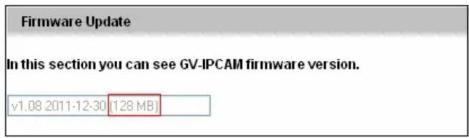
text_image
Firmware Update In this section you can see GV-IPCAM firmware version. v1.08 2011-12-30 (128 MB)- GV IP Device Utility
The “128 M” should appear under the NOTE column.
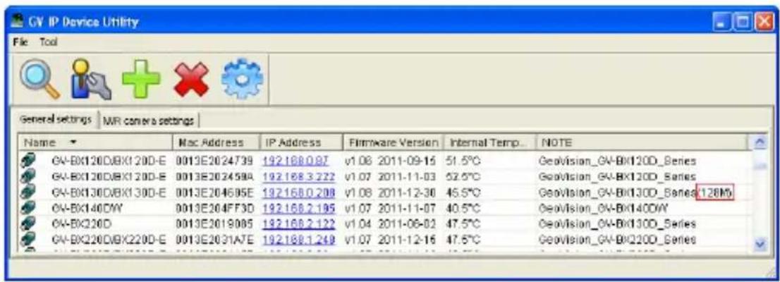
text_image
GV IP Device Utility File Tool General settings | NMR camera settings | Name Mac Address IP Address Firmware Version Internal Temp. NOTE GV-BX120DBX120D-E 0013E2024739 192168.0.87 v1.08 2011-09-15 51.5°C Geovision_GV-BX120D_Series GV-BX120DBX120D-E 0013E202459A 192168.3.222 v1.07 2011-11-03 52.5°C Geovision_GV-BX120D_Series GV-BX130DBX130D-E 0013E204695E 192168.0.208 v1.08 2011-12-30 45.5°C Geovision_GV-BX130D_Series 128M GV-BX140DY 0013E204FF3D 192168.2.195 v1.07 2011-11-07 40.5°C Geovision_GV-BX140DY GV-BX220D 0013E2019085 192168.2.122 v1.04 2011-06-02 47.5°C Geovision_GV-BX130D_Series GV-BX220DBX220D-E 0013E2031ATE 192168.1.249 v1.07 2011-12-16 47.5°C Geovision_GV-BX220D_SeriesJ. How to Remotely Reboot IP Cameras via FTP
Note this function is only available for GV-BX12201 firmware V1.02 or later.
- Enable Act as FTP server under FTP, Events and Alerts.
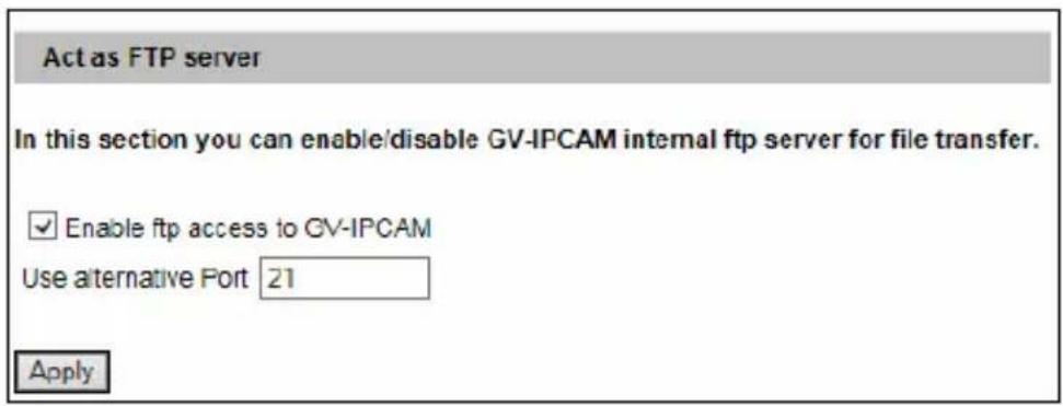
text_image
Act as FTP server In this section you can enable/disable GV-IPCAM internal ftp server for file transfer. ✓ Enable ftp access to GV-IPCAM Use alternative Port 21 Apply- In CMD.exe, type ftp
, e.g. ftp_192.168.0.10. - Type your account name and password.
- Type quote site reboot. The camera will be rebooted as indicated in the photo below.