E13A - Security Camera ACTi - Free user manual and instructions
Find the device manual for free E13A ACTi in PDF.


| Product Type | Security Camera |
| Brand | ACTi |
| Model | E13A |
| Image Sensor | 1/2.7" Progressive CMOS |
| Resolution | 2592 x 1944 (5 MP) |
| Lens | Fixed focal, 3.6mm (typical) |
| Minimum Illumination | 0.01 lux (color) |
| Video Compression | H.264 (High Profile, Main Profile, Baseline), MJPEG |
| Streaming | Dual stream |
| Network | 10/100 Ethernet, PoE (IEEE 802.3af) |
| Power | PoE or DC 12V |
| Audio | Two-way audio (built-in microphone and speaker) |
| Digital I/O | 1 input, 1 output |
| Local Storage | MicroSD slot (supports microSDHC/SDXC) |
| Operating Temperature | -10°C to 50°C |
| Dimensions (W x H x D) | 100mm x 100mm x 70mm (approx.) |
| Weight | 0.5 kg (approx.) |
| Software | Web Configurator, IP Utility |
| ONVIF | ONVIF Profile S compliant |
| Warranty | 2 years |
Frequently Asked Questions - E13A ACTi
User questions about E13A ACTi
0 question about this device. Answer the ones you know or ask your own.
Ask a new question about this device
Download the instructions for your Security Camera in PDF format for free! Find your manual E13A - ACTi and take your electronic device back in hand. On this page are published all the documents necessary for the use of your device. E13A by ACTi.
USER MANUAL E13A ACTi
natural_image
Abstract geometric design with a red square and a gray star-like shape (no text or symbols)Firmware User's Manual
A1D-500-V6.09.45-AC
2015/10/30
Table of Contents
Recommended PC Specifications 5
Preparation 6
Connect the Equipment 6
Configure the IP Addresses....6
Access the Camera....10
Live View 13
Login....13
Live View 14
View Modes....18
ePTZ View Mode.... 19
Panorama View Mode....20
Fisheye View Mode....21
PTZ Control Panel (For PTZ and Zoom Cameras)....22
How to Use Pan/Tilt 23
How to Set the Pan Limit.... 23
How to Zoom the Camera In or Out 24
How to Set the Home Position 25
How to Set Serial Hex Command Protocol 25
How to Adjust the Focus 25
How to Set Preset Points 26
How to Set Idle Time and Return Camera to Predefined Position...... 26
How to Set and Enable Tours.... 27
How to Use the Scan Function.... 28
Setup 30
Access the Setup Page 30
Host....31
Serial Setting.... 32
GPS Position.... 33
Date & Time....34
Network 36
IP Address Filtering....36
Port Mapping.... 38
HTTPS 40
IEEE 802.1X 41
SNMP Setting 43
RTP 46
Network (ToS, UPnP, Bonjour, ONVIF) 47
IP Settings....50
Connection Type 50
DNS 52
DDNS....53
Video & Audio ....56
Camera Options....56
Camera Calibration 62
Video....63
Motion Detection 66
Day/Night 71
Image 72
Exposure / White Balance.... 74
OSD 78
Privacy Mask 80
On-Screen Graphics 86
Audio....88
Event....89
Event Server 89
Event Configuration 92
Event List 100
Manual Event 104
Local Storage Management....105
Status.... 106
Utilities 107
File Management 112
System....114
User Account....114
System Info....115
Factory Default....116
Firmware Upload....117
Save & Reboot....119
Logout 120
Troubleshooting 121
Recommended PC Specifications
In order to configure or test the cameras, a PC with following basic specifications is needed:
| CPU | Core 2 Duo 2.13 GHz or above |
| Memory | 2 GB or above |
| Operating System | ● Windows XP with SP2 or above.● Windows 2003● Windows Vista● Windows 2008● Windows 7● Windows 8 |
| Browser for Accessing Firmware | ● Internet Explorer 8.0 or newer (full functionality)● Safari with QuickTime installed (partial functionality)● Other Browsers with Basic VLC Media Player (partial functionality) |
| Video Resolution | 1024x768 or higher |
Preparation
Connect the Equipment
To be able to connect to the camera firmware from your PC, both the camera and the PC have to be connected to each other via Ethernet cable. At the same time, the camera has to have its own power supply. In case of PoE cameras, you can use a PoE Injector or a PoE Switch between the camera and the PC. The cameras that have the DC power connectors may be powered on by using a power adaptor.
The Ethernet port LED or Power LED of the caxmera will indicate that the power supply for the camera works normally.
Configure the IP Addresses
In order to be able to communicate with the camera from your PC, both the camera and the PC have to be within the same network segment. In most cases, it means that they both should have very similar IP addresses, where only the last number of the IP address is different from each other. There are 2 different approaches to IP Address management in Local Area Networks – by DHCP Server or Manually.
Using DHCP server to assign IP addresses:
If you have connected the computer and the camera into the network that has a DHCP server running, then you do not need to configure the IP addresses at all – both the camera and the PC would request a unique IP address from DHCP server automatically. In such case, the camera will immediately be ready for the access from the PC. The user, however, might not know the IP address of the camera yet. It is necessary to know the IP address of the camera in other to be able to access it by using a Web browser.
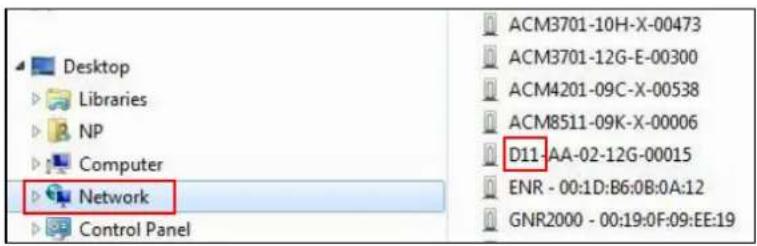
The quickest way to discover the cameras in the network is to use the simplest network search, built in the Windows system – just by pressing the “Network” icon, all the cameras of the local area network will be discovered by Windows thanks to the UPnP function support of our cameras.
In the example below, we successfully found D11 camera that we had just connected to the network.
text_image
Desktop Libraries NP Computer Network Control Panel ACM3701-10H-X-00473 ACM3701-12G-E-00300 ACM4201-09C-X-00538 ACM8511-09K-X-00006 D11-AA-02-12G-00015 ENR - 00:1D:B6:0B:0A:12 GNR2000 - 00:19:0F:09:EE:19With the left mouse click on D11 it is possible to automatically launch the default browser of the PC with the IP address of the target camera filled in the address bar of the browser already.
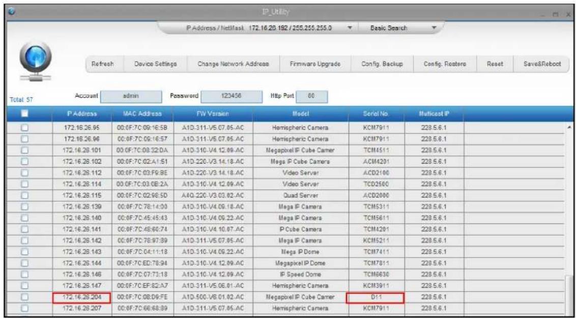
If you work with our cameras regularly, then there is even a better way to discover the cameras in the network – by using IP Utility. The IP Utility is a light software tool that can not only discover the cameras, but also list lots of valuable information, such as IP and MAC addresses, serial numbers, firmware versions, etc, and allows quick configuration of multiple devices at the same time.
The IP Utility can be downloaded for free from http://www.acti.com/IP_Utility
With just 1 click, you can launch the IP Utility and there will be an instant report as follows:
text_image
IP Utility P Address / NetMask 172.16.20.192 / 255.255.255.0 Basic Search Refresh Device Settings Change Network Addresses Firmware Upgrade Config. Backup Config. Resters Reset Save&Reboot Total 57 Account admin Password 123456 Http Port 80 P Address MAC Address FW Voraikn Model Serial No Maticeat IP 172.16.26.95 00:0F:7C 09:16:5B A1D-311-V5 07.05-AC Hemispheric Camera KCM7911 228.5.6.1 172.16.26.96 00:0F:7C 09:16:57 A1D-311-V5 07.05-AC Hemispheric Camera KCM7911 228.5.6.1 172.16.26.101 00:0F:7C 08:32:DA A1D-310-V4 12.09-AC Megapixel IP Cube Camer TCM4511 228.5.6.1 172.16.26.102 00:0F:7C 02:A1:51 A1D-220-V3 14.18-AC Mega IP Cube Camer ACM4201 228.5.6.1 172.16.26.112 00:0F:7C 03:F9:BE A1D-220-V3 14.18-AC Video Server ACD2100 228.5.6.1 172.16.26.114 00:0F:7C 03:0B:2A A1D-310-V4 12.09-AC Video Server TCD2500 228.5.6.1 172.16.26.115 00:0F:7C 02:98:5D A1D-220-V3 03:02-AC Quad Server ACD2000 228.5.6.1 172.16.26.139 00:0F:7C 78:14:00 A1D-310-V4 09:18-AC Mega IP Camera TCM5311 228.5.6.1 172.16.26.140 00:0F:7C 45:45:43 A1D-310-V4 09:22-AC Mega IP Camera TCM5611 228.5.6.1 172.16.26.141 00:0F:7C 45:60:74 A1D-310-V4 10:07-AC IP Cube Camera TCM4201 228.5.6.1 172.16.26.142 00:0F:7C 78:97:89 A1D-311-V5 07:05-AC Mega IP Camera KCM5211 228.5.6.1 172.16.26.143 00:0F:7C 04:11:18 A1D-310-V4 09:22-AC Mega IP Dome TCM7411 228.5.6.1 172.16.26.144 00:0F:7C ED:78:94 A1D-310-V4 12:09-AC Megapixel IP Dome TCM7811 228.5.6.1 172.16.26.148 00:0F:7C 07:73:18 A1D-310-V4 12:09-AC IP Speed Dome TCM6630 228.5.6.1 172.16.26.147 00:0F:7C EF:BZ:A7 A1D-311-V5 06:01-AC Hemispheric Camera KCM3911 228.5.6.1 172.16.26.204 00:0F:7C 08:D9:EFE A1D-50C-V6 01:02-AC Megapixel IP Cube Camer DII 228.5.6.1 172.16.26.207 00:0F:7C 66:68:89 A1D-311-V5 07:05-AC Hemispheric Camera KCM7911 228.5.6.1You can quickly notice the D11 model in the list. Click on the IP address to automatically launch the default browser of the PC with the IP address of the target camera filled in the address bar of the browser already.
Use the default IP address of a camera:
If there is no DHCP server in the given network, the user may have to assign the IP addresses to both PC and camera manually to make sure they are in the same network segment.
When the camera is plugged into network and it does not detect any DHCP services, it will automatically assign itself a default IP:
192.168.0.100
Whereas the default port number would be 80. In order to access that camera, the IP address of the PC has to be configured to match the network segment of the camera.
Manually adjust the IP address of the PC:
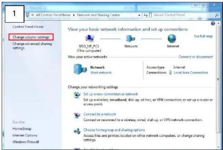
In the following example, based on Windows 7, we will configure the IP address to 192.168.0.99 and set Subnet Mask to 255.255.255.0 by using the steps below:
text_image
1 Control Panel Home Change adapter settings Change advanced sharing settings View your basic network information and set up connections SISO_NP_PCI (The computer) Network Internet See full map View your active networks Connect or disconnect Network Work network Access type: Internet Connections: Local Area Connection Change your networking settings Set up a new connection or network Set up a wireless, broadband, dial-up, ad hoc, or VPN connection; or set up a router or access point. Connect to a network Connect or reconnect to a wireless, wired, dial-up, or VPN network connection. Choose homegroup and sharing options Access files and prints located on other network computers, or change sharing settings. See also HomeGroup Internet Options Windows Firewall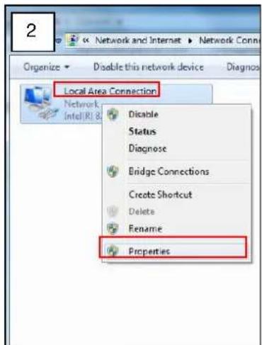
text_image
2 Network and Internet ▶ Network Conn Organize ▼ Disable this network device Diagnosis Local Area Connection Network Intel(R): 8 Disable Status Diagnose Bridge Connections Create Shortcut Delete Rename Properties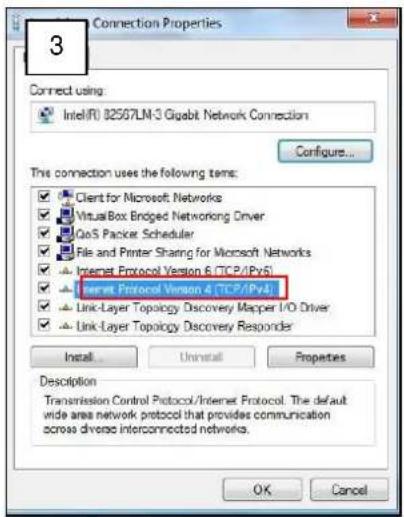
text_image
3 Connect using: Intel(R) 82567LM-3 Gigabit Network Connection Configure... This connection uses the following items: ✓ Client for Microsoft Networks ✓ Virtual Box Ended Networking Driver ✓ QoS Packet Scheduler ✓ File and Printer Sharing for Microsoft Networks ✓ Internet Protocol Version 6 (TCP/IPvS1) ✓ Internet Protocol Version 4 (TCP/IPvS1) ✓ Link-Layer Topology Discovery Mapper I/O Driver ✓ Link-Layer Topology Discovery Responder Install... Uninstall... Properties Description Transmission Control Protocol/Internet Protocol. The default wide area network protocol that provides communication across diverse interconnected networks. OK Cancel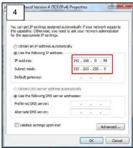
text_image
4 You can get IP settings assigned automatically if your network supports this capability. Otherwise, you need to ask your network administrator for the appropriate IP settings. Obtain an IP address automatically Use the following IP address: IP address: 192 . 168 . 0 . 99 Submit mask: 255 . 255 . 255 . 0 Default gateway: . Obtain DNS server address automatically Use the following DNS server addresses: Preferred DNS server: . Alternate DNS server: . Validate settings upon exit Advanced... OK CancelManually adjust the IP addresses of multiple cameras:
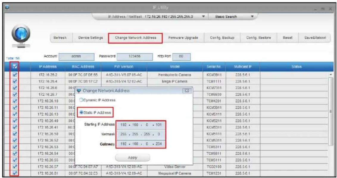
If there are more than 1 camera to be used in the same local area network and there is no DHCP server to assign unique IP addresses to each of them, all of the cameras would then have the initial IP address of 192.168.0.100, which is not a proper situation for network devices – all the IP addresses have to be different from each other. The easiest way to assign cameras the IP addresses is by using IP Utility:
text_image
IP Utility IP Address / Natllast: 172.16.26.192 / 255.255.255.0 Refresh Device Settings Change Network Address Firmware Upgrade Config, Backup Config, Restore Reset Save&Reboot Total: 56 Account 80min Password 123456 Http Port 80 IP Address MAC Address FW Version Model Serial No Multicast IP Status 172.16.26.2 00 OF 7C.07 DE.65 A1D-311-V5.07.05-AC Hemispheric Camera KCM3911 228.5.6.1 172.16.26.4 00 OF 7C.08 17:C2 A1D-310-V4.12.02-AC Mega P Camera TCM1111 228.5.6.1 172.16.26.6 00 172.16.26.7 00 172.16.26.10 00 172.16.26.11 00 172.16.26.13 00 172.16.26.40 00 172.16.26.41 00 172.16.26.50 00 172.16.26.52 00 172.16.26.53 00 172.16.26.54 00 172.16.26.55 00 172.16.26.57 00 OF 7C:04 87:A7 A1D-310-V4.12.05-AC Video Server TCO2100 228.5.6.1 172.16.26.01 00 OF 7C:04:32:E3 A1D-310-V4.12.05-AC Megapixel IP Camera TCM1231 228.5.6.1With the procedure shown above, all the cameras will have unique IP addresses, starting from 192.168.0.101. In case there are 20 cameras selected, the last one of the cameras would have the IP 192.168.0.120.
Later, by pressing the "Refresh" button of the IP Utility, you will be able to see the list of cameras with their new IP addresses.
text_image
RefreshPlease note that it is also possible to change the IP addresses manually by using the Web browser. In such case, please plug in only one camera at a time, and change its IP address by using the Web browser before plugging in the next one. This way, the Web browser will not be confused about two devices having the same IP address at the same time.
Access the Camera
Now that the camera and the PC are both having their unique IP addresses and are under the same network segment, it is possible to use the Web browser of the PC to access the camera.
You can use any of the browsers to access the camera, however, the full functionality is provided only for Microsoft Internet Explorer.
The browser functionality comparison:
| Functionality | Internet Explorer | Other browsers |
| Live Video | Yes | Yes* |
| Live Video Area Resizable | Yes | No |
| PTZ Control | Yes | Yes |
| Capture the snapshot | Yes | Yes |
| Video overlay based configuration (Motion Detection regions, Privacy Mask regions) | Yes | No |
| All the other configurations | Yes | Yes |
* When using non-Internet Explorer browsers, free third-party software plug-ins must be installed to the PC first to be able to get the live video feed from the camera:
| Browser | Required Plug-In |
| Safari | QuickTime (http://www.apple.com/quicktime/download/) |
| Any Other Browser | Basic VLC Media Player (http://www.videolan.org) |
Disclaimer Notice: The camera manufacturer does not guarantee the compatibility of its cameras with QuickTime and VLC – since they are third party softwares; the third party has the right to modify their utility any time which might affect the compatibility. In such cases, please use Internet Explorer browser instead.
When using Internet Explorer browser, the ActiveX control for video stream management will be downloaded from the camera directly – the user just has to accept the use of such control when prompted so. No other third party utilities are required to be installed in such case.
The following examples in this manual are based on Internet Explorer browser in order to cover all functions of the camera.
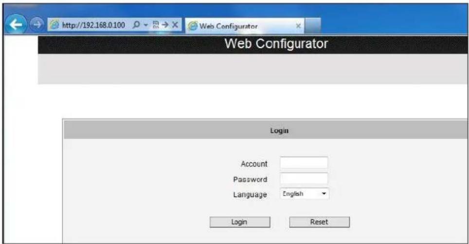
Assuming that the camera's IP address is 192.168.0.100, you can access it by opening the Web browser and typing the following address into Web browser's address bar:
http://192.168.0.100
Upon successful connection to the camera, the user interface called Web Configurator would appear together with the login page. The HTTP port number was not added behind the IP address since the default HTTP port of the camera is 80, which can be omitted from the address for convenience.
text_image
http://192.168.0.100 Web Configurator Web Configurator Login Account Password Language English Login ResetBefore logging in, you need to know the factory default Account and Password of the camera.
Account: Admin
Password: 123456
Using IPv6 to Access the Camera
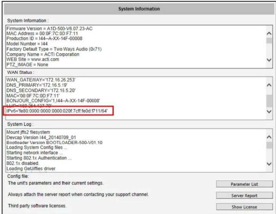
The camera is IPv6-ready and has been assigned its unique static IPv6 address. The IPv6 address can be found under the System > Sytem Info menu (see System Info on page 115 for more information).
text_image
System Information System Information : Firmware Version = A1D-500-V6.07.23-AC MAC Address = 00:0F:7C:0D:F7:11 Production ID = I44--A-XX-14F-00008 Model Number = I44 Factory Default Type = Two Ways Audio (0x71) Company Name = ACTi Corporation WEB Site = www.acti.com PTZ_IMAGE = None WAN Status : WAN_GATEWAY='172.16.26.253' DNS_PRIMARY='172.16.5.19' DNS_SECONDARY='172.16.5.20' MAC='00:0F:7C:0D:F7:11' BONJOUR_CONFIG='1,I44--A-XX-14F-00008' LIP='160.254-137.70' IPv6='fe80:0000:0000:0000:020f:7cff.fe0d:f711/64' System Log : Mount jffs2 filesystem Devcap Version I44_20140709_01 Bootloader Version BOOTLOADER-500-V01.10 Loading System Config files ... Starting network interface ... Starting 802.1x Authentication ... 802.1x disabled. Loading GetJiffies driver Config file: The unit's parameters and their current settings. Parameter List Always attach the server report when contacting your support channel. Server Report Third party software licenses. Show LicenseTo access the camera with the IPv6 address, type the IPv6 address enclosed in square brackets on the web browser address bar. For example:
http://[fe80:0000:0000:0000:020f:7cff:fe0d:f711]
Live View
This section describes how to configure the IP camera. The administrator has unlimited access to all settings, while the normal user can only view live video.
Login
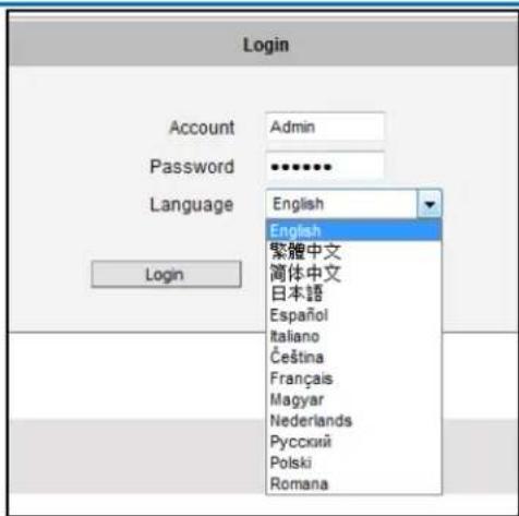
Initially there exists only administrator's account in the camera (Account: Admin, Password:
123456) – you have to use that account to log in. You can later create normal user accounts with limited access rights if necessary.
Feel free to choose your local language from the list of languages or keep it as English. After pressing "Login", you will be able to access the user interface of Web Configurator.
text_image
Login Account Admin Password ••••••• Language English English 繁體中文 簡体中文 日本語 Español Italiano Čeština Français Magyar Nederlands Русский Polski Romana LoginUpon successful login, you will be able to see the Live View page. In case of Internet Explorer browser, you may be prompted to allow the installation of ActiveX control from the camera. Press "Install" then. The live video will appear shortly after that.
Live View
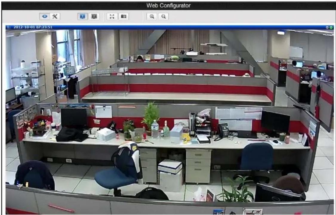
The live view will appear automatically with the video resolution of 1280x720 (1MP cameras) or 1920x1080 (2-5MP cameras).
text_image
Web Configurator 1: 2012-10-01 07:23:51While being on the Live View page, the Live View icon appears as being pressed: If you leave the Live View page, you can later return by pressing that button.

The buttons shown on the Live View page vary depending on the functions supported by the camera.
If the resolution of the PC's monitor is bigger than the resolution of the live video, you will be able to see the whole size of the video immediately. If not, you will only see part of the video at first and you would have to use the scroll bars to see the rest of the video area. In order to see the whole video on your display, you can temporarily re-scale the video to better fit your screen by pressing the digital zoom buttons:

- Enlarge the video size digitally

- Reduce the video size digitally
Notice: These digital zoom adjustments do not influence the actual video resolution of the camera. Regardless of how large or small the video appears on the display after pressing the digital zoom buttons, the actual video stream size of the camera is the same as before.
You can also digitally re-scale the video to fully match the size of your display with just 1 click:

- Full screen Mode
You may use ESC key from the keyboard to exit the full screen mode.
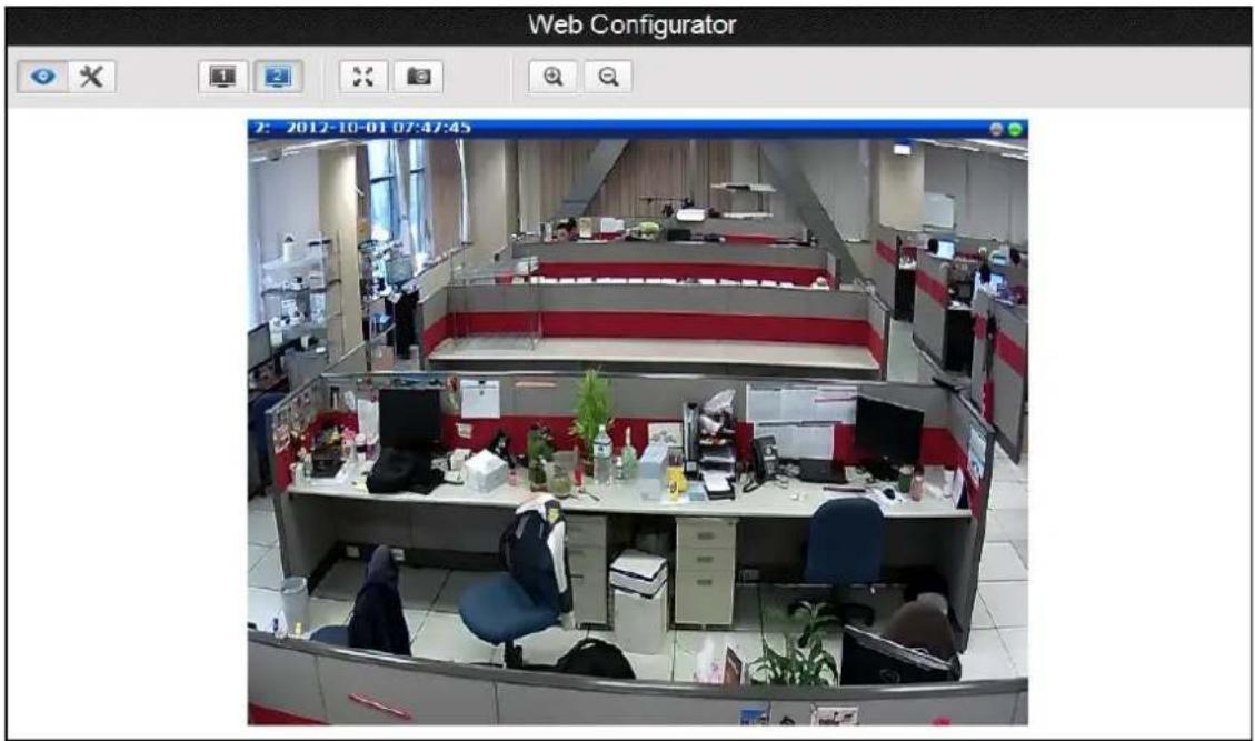
The cameras have the dual stream capability – the Stream 1 is usually the high resolution stream with the purpose of being recorded by NVR while Stream 2 has lighter video configuration for NVR live view purposes, to reduce the computing power of the NVR PC. Both streams can be configured under Web Configurator's Setup page. To see how each of the stream looks like, there are quick buttons on the Live View page:

- Show the Stream 1 video

- Show the Stream 2 video
When pressing the Stream 2 button, the Live View would look like this:
text_image
Web Configurator 2: 2012-10-01 07:47:45To capture the snapshots of the current live view, press the snapshot button. The snapshots are saved in Pictures folder.

- Take a Snapshot
Cameras with audio function have the audio controls on Live View page.

- Speak to Camera
To speak to the camera, press the

button. If the camera is connected to a network video
recorder, the audio will be recorded with the video stream.
To adjust the volume level of the speakers connected to the PC that runs the Web Configurator in order to hear the audio from the camera's microphone or line-in device, use the audio controls as below:
Audio Muted:
Audio level adjusted to the maximum:
This volume control appears on the user interface only when the Audio-in function of the camera has been "Enabled" under Setup page.
The digital output controls appear on the Live View page of the cameras with digital input/output function. The controls allow users to manually trigger a DO device.

- Select DO Port
Each DO ports are controlled separately. For cameras with more than one DO ports, select the
DO port and press to set the output power level to high or to set the output power level
to low. Consequently, setting the port to a high power level "activates" the DO device and setting the port to a low power level "deactivates" the DO device. For example, if an alarm is set as DO1
and is pressed, the alarm will continuously sound until is pressed to deactivate the device.
View Modes
For Hemispheric and Fisheye cameras, the Miniature Fisheye-View and View Mode buttons appear on the Live View screen.
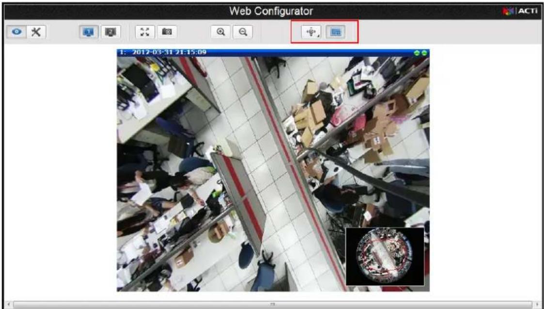
text_image
Web Configurator 1: 2012-03-31 21:15:09By default, a miniature of the Fisheye view is shown on the lower right corner of the Live View,
press to hide the miniature fisheye-view or to display it.
You can change the viewing mode into:

- ePTZ View Mode

- Panorama View Mode

- Fisheye View Mode
ePTZ View Mode
ePTZ mode works as an optical PTZ (pan-tilt-zoom) function. You can change the viewing direction by moving the mouse over the Live View screen and clicking towards the direction you wish to view. The mouse cursor is represented by a red "+" mark.
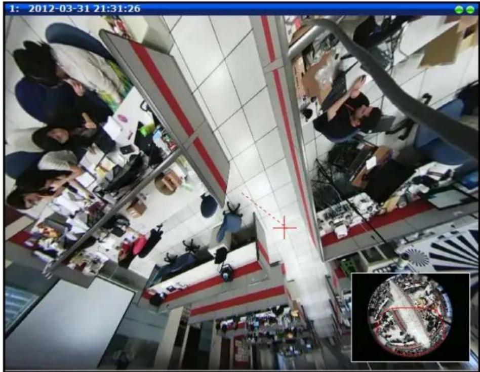
text_image
1: 2012-03-31 21:31:26If Miniature Fisheye-view is enabled, the current direction and scope of view is shown on the Miniature Fisheye-view window with the red marking.
Panorama View Mode
This mode allows you to view the camera in panorama view where details can be seen more clearly. When the camera is installed on the ceiling, there will be two panorama views, one for the upper hemisphere and another for the lower hemisphere. The lower hemisphere is displayed with an inverted direction when viewed on panorama.
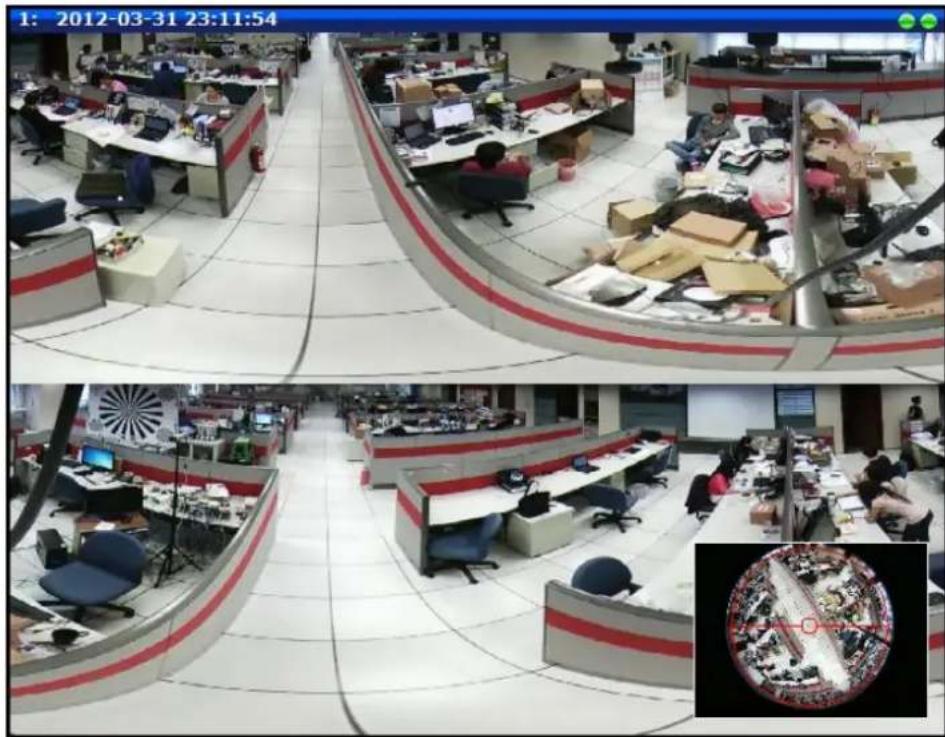
text_image
1: 2012-03-31 23:11:54 1: 2012-03-31 23:11:54If Miniature Fisheye-view is enabled, the current scope of view is shown on the Miniature Fisheye-view window with the red marking.
Fisheye View Mode
This mode shows the camera view as though viewing from a fish's eye with the whole viewing angle in sight but details may be too small and not be seen clearly.
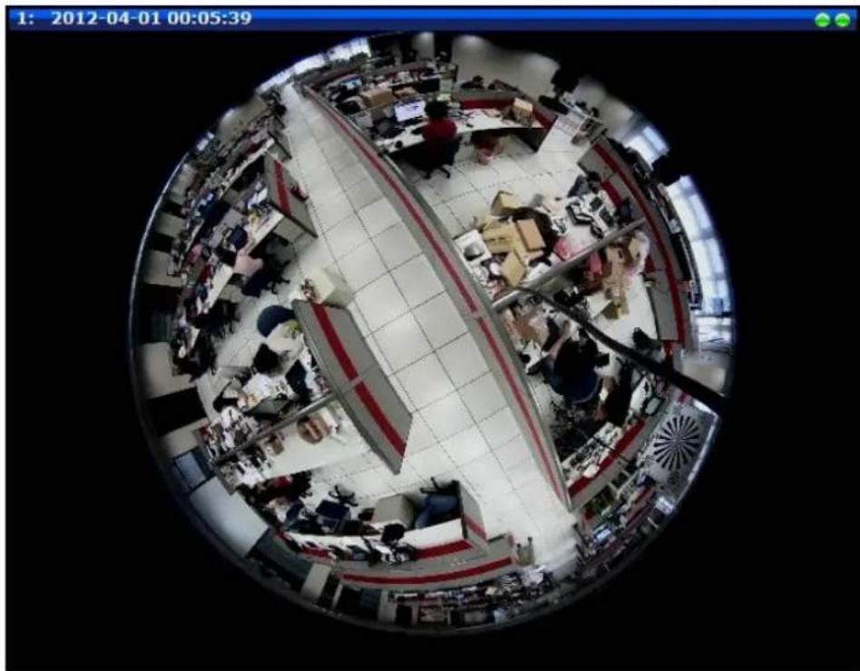
natural_image
Aerial fisheye view of a busy retail or office space with multiple workstations and customers (no visible text or signage)PTZ Control Panel (For PTZ and Zoom Cameras)
For PTZ and zoom camera models, click the PTZ button

on the Live View screen to
display the PTZ Control Panel. For PTZ cameras, the PTZ button can be one of the following:

Joystick Mode
This is the basic PTZ button. When the PTZ Control Panel is open, instead of using the pan/tilt controls, move the mouse cursor over the Live View, the mouse cursor will turn into zoom in/out or directional icons (e.g. / / / / etc.). Click or drag the mouse to zoom in/out or pan/tilt the camera view.

Mouse Mode
When the PTZ Control Panel is open, a red cross-hair (+) icon appears. Just like using a PC with a mouse, users may draw a box using the mouse on the Live View area and the camera will zoom in on the boxed area. Scroll down the mouse wheel to zoom out and scroll up to zoom in. To pan the camera, double-click the mouse towards the direction you want to pan.
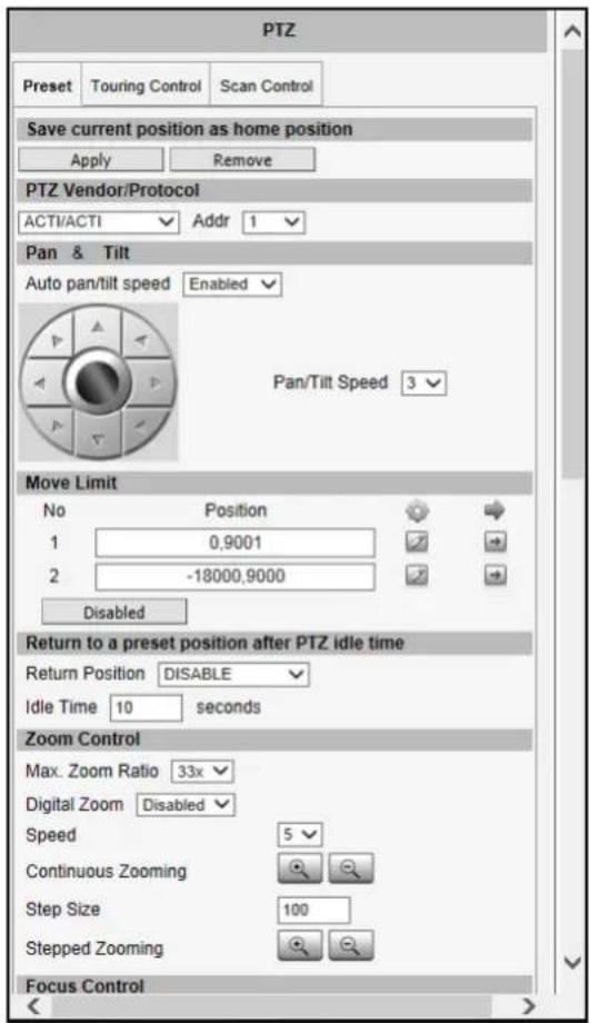
On the PTZ Control Panel, users can do any the following:
- Set the home position
- Set the serial hex command protocol and address
- Pan the camera
- Set the pan limitation (PTZ and speed dome only)
- Zoom the camera in or out as well as adjust the zoom speed and step size
- Set the focus to auto refocus or manual
- Set Preset points for touring
- Set Camera Tour
- Set Scan function (PTZ and Speed Dome only)
NOTE: The PTZ Control Panel may differ depending on camera model.
text_image
PTZ Preset Touring Control Scan Control Save current position as home position Apply Remove PTZ Vendor/Protocol ACTI/ACTI Addr 1 Pan & Tilt Auto pan/tilt speed Enabled Pan/Tilt Speed 3 Move Limit No Position 1 0,9001 2 -18000,9000 Disabled Return to a preset position after PTZ idle time Return Position DISABLE Idle Time 10 seconds Zoom Control Max. Zoom Ratio 33x Digital Zoom Disabled Speed 5 Continuous Zooming Step Size 100 Stepped Zooming Focus ControlHow to Use Pan/Tilt
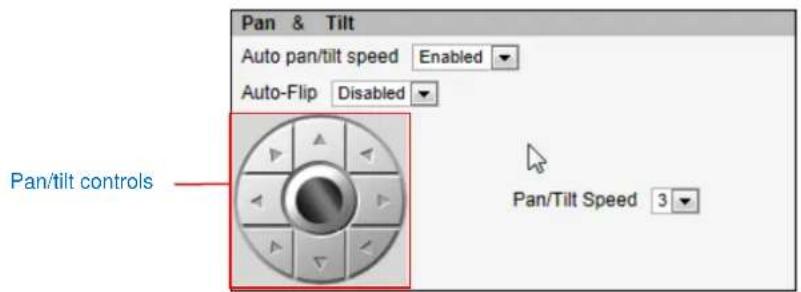
For PTZ / speed dome cameras, click the pan/tilt controls to pan/tilt the camera.
text_image
Pan & Tilt Auto pan/tilt speed Enabled Auto-Flip Disabled Pan/tilt controls Pan/Tilt Speed 3Other pan/tilt features include:
- Auto pan/tilt speed: When "Enabled", the camera automatically sets the pan/tilt speed according to the zoom ratio and the selected pan/tilt speed while retaining the clarity and quality of image even as the camera is panning or tilting. When "Disabled", the pan/tilt speed follows the value selected on the Pan/Tilt Speed field.
- Auto-Flip: When "Enabled", the camera automatically flips the image when the camera is pan at 180° and then continues panning to the same direction up to 360 °. When "Disabled", users can only pan the camera to one direction up to 180°.
NOTE: Available only in PTZ 19x camera models.
- Pan/Tilt Speed: Select the desired pan/tilt speed. The bigger the number, the faster the speed is.
TIP: While the PTZ Control Panel is open, instead of using the pan/tilt controls, move the mouse cursor over the Live View. Click or drag the mouse to zoom in/out or pan/tilt the camera view.
How to Set the Pan Limit
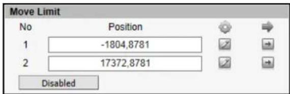
For PTZ / Speed dome cameras, users can limit the pan movement of the camera from one point to another.
text_image
Move Limit No Position 1 -1804,8781 2 17372,8781 DisabledTo set the pan movement limit, do the following:
- Pan the camera to the starting target area of limitation, then click the ☐ to set that area as the first limit. The position coordinates appear on the Position box.
- Pan the camera to the ending target area of limitation, then click the corresponding button to set that area as the other limit. The position coordinates appear on the Position box.
To disable this limitation, click the Disabled button.
To go to the limitation points directly, click

How to Zoom the Camera In or Out
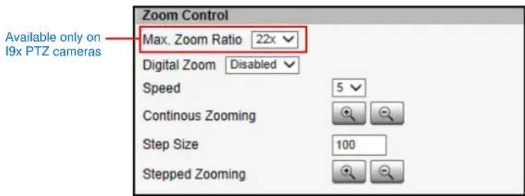
Zooming can be done continuously or by one step (one click) at a time.
text_image
Available only on 19x PTZ cameras Zoom Control Max. Zoom Ratio 22x Digital Zoom Disabled Speed 5 Continuous Zooming Step Size 100 Stepped ZoomingTo zoom continuously, do the following:
- On Zoom Control, select the Speed, wherein the bigger the number, the faster is the zooming speed.
- Click and hold the left mouse button on zoom in or zoom out. When the mouse button is released, zooming stops.
To zoom by step zooming, do the following:
- On Zoom Control, enter the desired step size. Size is the amount of zoom scale taken in each step.
- Click the left mouse button on zoom in 🔒 or zoom out 🔒. One zoom step is taken for each click.
For PTZ camera models, users can enable the Digital Zoom feature. When enabled, once the optical zoom reached its maximum, the camera continues to zoom in the image using digital zoom.
TIP: While the PTZ Control Panel is open, instead of using buttons, move the mouse cursor over the Live View, the mouse cursor will turn into zoom in/out (e.g. +). Click or drag the mouse to zoom in/out the camera view. Or, if in Mouse mode, draw a box on the area you want to zoom in to.
For PTZ cameras with zoom ratio of 18x and above, like the I9x models, users can set the Max. Zoom Ratio on the user interface. Setting the maximum zoom ratio helps to ensure that focus is kept all throughout the zoom in/out process. For other cameras with optical zoom lens, setting the maximum zoom ratio can be done through the URL command.
How to Set the Home Position

text_image
Save current position as home position Apply Remove- Pan, tilt, and zoom on the area that you want to set as the home position.
- Click the Apply button on the Save current position as home position.
How to Set Serial Hex Command Protocol

text_image
PTZ Vendor/Protocol ACTI/ACTI Addr 0ACTi cameras and video management systems fully support the URL Command, a high level PT command set. However, in case the cameras will be used with devices from third party vendors that only support Serial Hex Command (low level PT command set), users must select the PTZ Vendor/Protocol to use and its address. Otherwise, leave the default settings.
How to Adjust the Focus
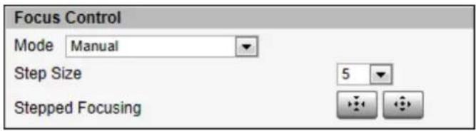
After zooming the camera in or out, it is recommended to readjust the focus in Focus Control.
text_image
Focus Control Mode Manual Step Size 5 Stepped FocusingOptions are:
- Auto Refocus after Zoom: Select this option to let the camera automatically adjust the focus after zooming.
- Manual: Select this option to manually adjust the focus. This feature is useful if the automatic focus position is not the position that the user wants to achieve. To adjust the focus manually, select the Step Size and then click the step focus in or focus out icons until the desired focus is achieved.
When an option is selected, click the Refocus button to apply the focus adjustment.
How to Set Preset Points
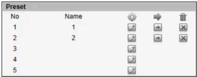
Preset points are user-defined areas that the camera can pan or zoom in to. A series of preset points can be grouped as one Tour.
text_image
Preset No Name 1 1 2 2 3 4 5To create a preset point, do the following:
- On Preset, click a icon to start creating a preset point.
- Under the Name field, type a preset point name.
- Pan, tilt, and zoom on the area that you want to set as the preset point.
- Once done, click the icon again to close and complete the preset point.
- Repeat the above procedures to create more preset points.
To go to the preset point directly, click To delete the preset point, click
How to Set Idle Time and Return Camera to Predefined Position
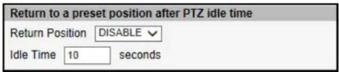
This feature allows the camera to go directly to a predefined position after an idle period of time. Idle time refers to the time when the camera has no operation like pan, tilt, zoom or tour activity.
text_image
Return to a preset position after PTZ idle time Return Position DISABLE Idle Time 10 secondsTo set the camera to go to a predefined position, do the following:
- On Return Position, select one of the following options:
a. Home Position: The camera will go to the Home position as defined in How to Set the Home Position on page 25.
b. Preset point name: The camera will go to the preset point which is already configured (see How to Set Preset Points on page 26).
c. DISABLE: To disable this function.
- On Idle Time, type the duration of time (seconds) wherein the camera is considered idle.
How to Set and Enable Tours
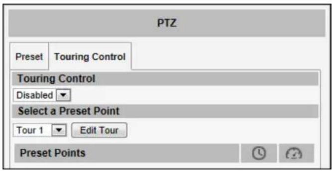
Once a preset point is created, the Touring Control page tab appears. Click the Touring Control page tab to configure the Preset Tour. A Preset Tour directs the camera to cycle through a sequence of preset points and stay on each preset point for a specific time.
text_image
PTZ Preset Touring Control Touring Control Disabled Select a Preset Point Tour 1 Edit Tour Preset PointsTo set or modify a tour, do the following:
- On Select a Preset Point, select a tour and then click Edit Tour.
- Select a preset point from the list, set the duration (sec) of how long the camera will stay in that point and the pan/tilt speed (the bigger the number, the faster the speed), and then click
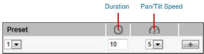
text_image
Duration Pan/Tilt Speed Preset 1 10 5- On the Preset Points, the preset points added to the Tour are listed.
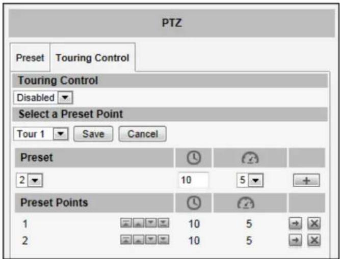
text_image
PTZ Preset Touring Control Touring Control Disabled Select a Preset Point Tour 1 Save Cancel Preset 2 10 5 + Preset Points 1 10 5 2 10 5- To change the sequence of preset points, click the (first / up / down / last) icons.
- To directly go to the preset point, click the icon.
-
To delete the preset point from the list, click the icon.
-
Repeat steps 2 and 3 to add more preset points to the tour.
-
Once done, click the Save button on Select a Preset Point.
-
On Touring Control, select the tour name to activate. Once activated, the camera will start the tour.
How to Use the Scan Function
The Scan function enables the camera to go from one predefined point to another by scanning the view horizontally without losing focus. Unlike in preset tours, wherein the camera goes to one preset point to another quickly and focusing only on the present point area, scan function goes over point 1 to point 2 on a steady pace with the whole viewing angle in complete focus. The scan speed can also be configured according to user preference.
Click the Scan Control page tab to configure scan function.
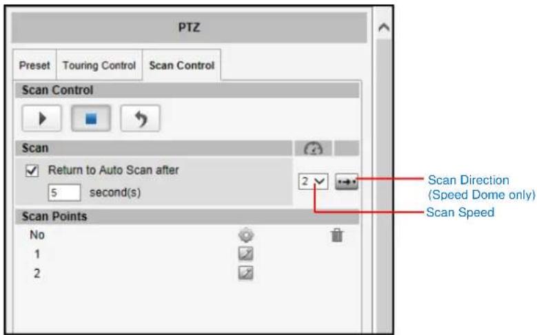
text_image
PTZ Preset Touring Control Scan Control Scan Control Scan Return to Auto Scan after 5 second(s) Scan Points No 1 2 Scan Direction (Speed Dome only) Scan SpeedTo set or modify scan points, do the following:
-
On Scan Points, click the icon of scan point 1 to set the scan starting point.
-
Pan and tilt on the area that you want to set as scan point 1.
-
Once done, click the 📋 icon again to close and complete first scan point.
-
Click the icon of scan point 2 to set the scan ending point.
-
Pan and tilt on the area that you want to set as the ending point.
-
Once done, click the 📋 icon again to close and complete scan point 2.
-
Select the preferred Scan Speed (the bigger the number, the faster the speed).
-
Select the preferred Scan Direction: Clockwise or counter-clockwise (this features is available only in speed dome cameras.
When a scan point has been set, the corresponding Delete icon appears. To remove the scan point, click 📧
Scan function is supported only in PTZ cameras and box cameras with serial ports. For box cameras, the scan function works when a PT scanner is connected to the camera via serial port connection. See Serial Setting on page 32.
How to Manage Scan
To start scanning, click

To restart scanning from the starting point while scanning is in progress, click

To stop scanning, click

When scanning is interrupted by other camera operation, like pan, tilt, zoom, etc., checking Return to Auto Scan after box enables the camera to resume scan function after the defined period of time (seconds).
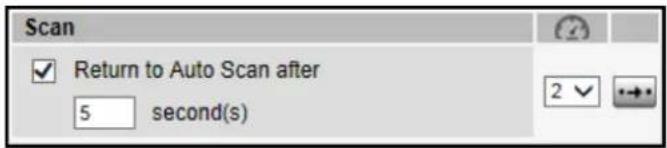
text_image
Scan ✓ Return to Auto Scan after 5 second(s)Setup
The following chapters guide you through the Setup functions of the camera.
Access the Setup Page
To configure any of the camera settings, go to the Setup menu by pressing the following button on Live View page:

- Go to Setup
text_image
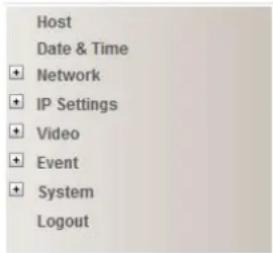
Host Date & Time Network IP Settings Video Event System LogoutThe left side of the Setup page contains the list of Setup items.
Notice: The exact content of the menu list varies for each camera, depending on the actual capabilities of each camera. This manual, however, is designed to explain all the possible functions.
Several items in the Setup page are divided into groups, such as Network, IP Settings, etc. You can expand the groups to see the sub-items by pressing the [+] button.
The following chapters of this manual explain each Setup item separately. The chapters are listed in the same order as the list of Setup menu items.
Host

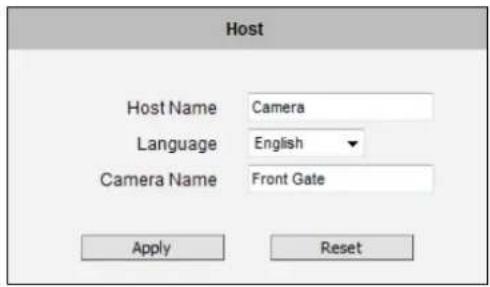
The section "Host" allows the administrator to define the name of the
camera and preferred user interface language.
text_image
Host Host Name Camera Language English Camera Name Front Gate Apply ResetThere are two kinds of names – Host Name and Camera Name.
Host Name is used to identify the camera by a DHCP server. In some networks with very strict security policy, it is required that all the network devices should have their host name, and when the devices attempt to access the network by requesting an IP address from a DHCP server, the DHCP server would check if the host name is among the allowed devices. On this page, it is possible to edit the Host Name. To actually include the Host Name in DHCP discovery packet sent from a camera, please go to IP Settings and make sure the device is in Dynamic IP Address mode and "Use host name" is checked.
Camera Name is used to identify the device by Video Management System or by Software Tools. Usually, upon installation of the camera, the actual installation location is used as an easy-to-remember Camera Name, such as "Front Gate" or "Elevator 1". In many cases the VMS is able to modify the Camera Name directly via its own user interface without needing to access Web Configurator.
Language selection under Host has the same purpose as the one on the login page of Web Configurator.
After changing any of the items above, press Apply to save the changes. The Reset button undoes the changes that had just been made but not Applied yet.
Serial Setting
This section allows the user to set the serial port configuration of the camera to synchronize it with the serial port configurations of a Pan-Tilt (PT) device.
NOTE: This section appears only if the camera has a serial port connector.

text_image
Serial Setting Serial Port Control 8,None,1 Serial Port Baud Rate 9600 Apply ResetSerial Port Control: Select the serial port control that matches with the serial port configured on the PT device. This function is equivalent to the DIP switch of the PT device.
Serial Port Baud Rate: Select the serial port baud rate that matches with the baud rate set on the PT device.
After changing any of the items above, press Apply to save the changes. The Reset button undoes the changes that had just been made but not applied yet.
GPS Position
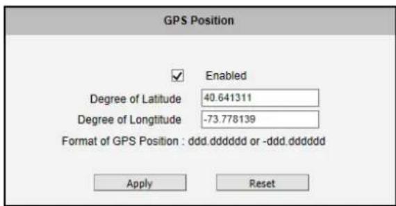
This section allows users to manually set the GPS position of the camera and find the location of the camera on the map when using a Network Video Recorder (NVR).
text_image
GPS Position Enabled Degree of Latitude 40.641311 Degree of Longitude -73.778139 Format of GPS Position : ddd.dddddd or -ddd.dddddd Apply ResetCheck the Enabled box to enable this feature.
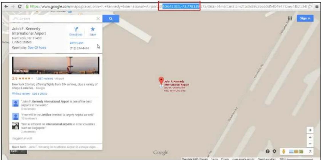
Find the camera location on google maps, for example, installed in the airport.
text_image
https://www.google.com/maps/place/john+F-Kennedy-International+Airport JPK airport John F. Kennedy International Airport New York, NY 11430 United States Open today. Open 24 hours Directions Save panyn.com (718) 244-8444 100 Prices 3.9 ★★★★ 1.087 reviews - Airport New York City hub offering flights from 80+ airlines, plus a variety of shops & suites. - Google Write a review Add a photo *John F. Kennedy International Airport is one of the best airports in the world." 8 reviewers *Free wifi in the JetBlue terminal is largely helpful as well." 10 reviewers *Not as efficient as international airports in other countries such as Singapore" 2 reviewers Suggest an exit! Quick facts John F. Kennedy International Airport is a major sign... Google http://www.google.com/maps/place/john+F-Kennedy-International+Airport JPK airport Sign In John F. Kennedy International Airport Airport setting the new york city areaCopy the first GPS coordinates from the URL bar and paste it on Degree of Latitude. Copy the second part of the GPS coordinates to Degree of Longitude.
Press Apply to save the changes.
Date & Time
Each video frame contains a time stamp. The accuracy of the time stamp is very important for incident investigators. Therefore the clock of the camera has to be adjusted to most accurate time possible.
Date & Time
The section Date & Time provides the options for adjusting the date
and time of the camera.
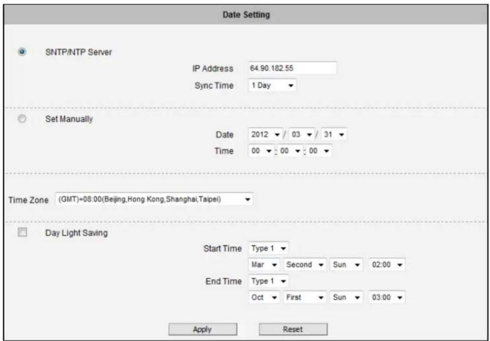
There are two ways to adjust the date and time – automatically by getting date and time regularly from any of the NTP servers worldwide, or manually by selecting proper time zone, date and time. The automatic way can be used only if the camera has an access to NTP servers. If you are using an isolated Local Area Network without Internet access, you can only use Manual date and time adjustment mode.
text_image
Date Setting SNTP/NTP Server IP Address 64.90.182.55 Sync Time 1 Day Set Manually Date 2012 / 03 / 31 Time 00 00 00 Time Zone (GMT)+08:00(Beijing,Hong Kong,Shanghai,Taipei) Day Light Saving Start Time Type 1 Mar Second Sun 02:00 End Time Type 1 Oct First Sun 03:00 Apply ResetWhen choosing SNTP/NTP Server for automatic date and time updating, you can key in the IP address of the NTP server and the time interval for automatic time synchronization. If you want to key in the domain name of NTP server instead, please make sure the DNS server IP address has been set under IP Settings; otherwise the camera will not be able to resolve the domain name of the NTP server.
If all the cameras are getting the date and time from the same NTP Server, you can be most sure that the video clips from different cameras can be well synchronized later for comparison purposes.
To choose the most suitable NTP Server to synchronize date and time with, please refer to the worldwide pool of NTP Servers: http://www.pool.ntp.org/en/
When choosing Set Manually mode, you can adjust the date and time by the select boxes. Choose the appropriate Time Zone from the select box, too. If your location is not listed there, then pick any of the listed zones which GMT is identical with your location.
For the countries with daylight saving policy, there is Day Light Saving function with two different types:
Type 1 – define the starting or ending time of daylight saving period by the number of the week in the month (First, Second, Third or Last week).
Type 2 - define the starting or ending time of daylight saving period by the exact date in the month (1-31).
Whether to choose Type 1 or Type 2, please refer to the daylight saving policy of given country.
After changing any of the items above, press Apply to save the changes. The Reset button undoes the changes that had just been made but not Applied yet.
Network
Network
The section Network provides the list of network related functions
and services. The [+] mark before Network indicates that the list can be expanded by clicking on it. Once expanded, the list can later be collapsed again by clicking on the [-] mark.
IP Address Filtering
IP Address Filtering
By "IP Address Filtering" function it is possible to define which
devices (their IP addresses) are allowed to connect to this camera, and which devices are forbidden to connect to this camera.
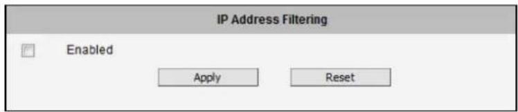
Check the box "Enabled" to activate the IP address filtering function and press Apply.
text_image
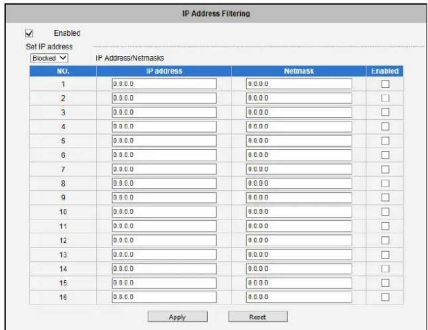
IP Address Filtering Enabled Apply ResetBelow you can select either "Allowed" or "Blocked" list to add items there and Enable them with the checkbox behind each row.
text_image
IP Address Filtering Enabled Set IP address Blocked ▼ IP Address/Netmasks NO. IP address Netmask Enabled 1 0.0.0 0.0.0 2 0.0.0 0.0.0 3 0.0.0 0.0.0 4 0.0.0 0.0.0 5 0.0.0 0.0.0 6 0.0.0 0.0.0 7 0.0.0 0.0.0 8 0.0.0 0.0.0 9 0.0.0 0.0.0 10 0.0.0 0.0.0 11 0.0.0 0.0.0 12 0.0.0 0.0.0 13 0.0.0 0.0.0 14 0.0.0 0.0.0 15 0.0.0 0.0.0 16 0.0.0 0.0.0 Apply Reset"Allowed" mode will refuse access to all IP addresses except the ones listed below.
"Blocked" mode will accept all incoming access except the IP addresses listed below.
Using Netmask (Subnet Mask) allows you to set filtering for a whole range of IP address at once, without the need to enter all of them individually. If you are not sure about the function of Netmask, then you should use 255.255.255.255, and it will affect only a single IP address per line of entry, or use 255.255.255.0 to use the same setting for all IP addresses starting with the same three numbers.
After changing any of the items above, press Apply to save the changes. The Reset button undoes the changes that had just been made but not Applied yet.
Warning! Do not accidentally block your own IP address that you are connecting from; otherwise you will not be able to access the camera any more to undo the changes. If this happens by mistake, you can do the hardware reset – it will clear all the filtering rules.
Port Mapping
Port Mapping
The section Port Mapping provides the list of services and protocols
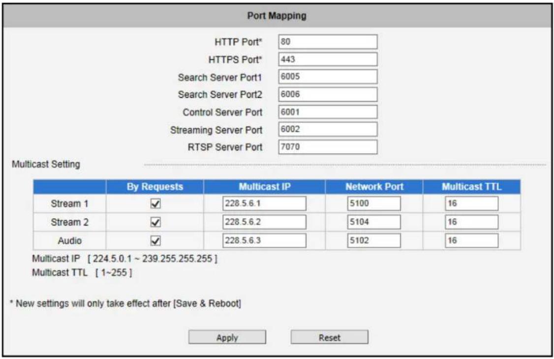
that require their own port number for communication. By default, the camera already has all the ports defined. On this page, the user can modify the port numbers in case there is a specific need for that. Most often, the HTTP port is changed to something other than 80 in order to match with easy-to-remember port forwarding rules of the router that acts as a bridge between local area network and Internet.
text_image
Port Mapping HTTP Port* 80 HTTPS Port* 443 Search Server Port1 6005 Search Server Port2 6006 Control Server Port 6001 Streaming Server Port 6002 RTSP Server Port 7070 Multicast Setting By Requests Multicast IP Network Port Multicast TTL Stream 1 ✓ 228.5.6.1 5100 16 Stream 2 ✓ 228.5.6.2 5104 16 Audio ✓ 228.5.6.3 5102 16 Multicast IP [ 224.5.0.1 ~ 239.255.255.255 ] Multicast TTL [ 1~255 ] * New settings will only take effect after [Save & Reboot] Apply ResetNOTE: Some items appear only if the camera model supports the function.
| Parameters | Description |
| HTTP port | Select the port assigned for HTTP protocol access. |
| HTTPS Port | Select the port assigned for HTTPS protocol access. |
| Search Server Port1 | Select the first port used by server search applications to detect this IP device (e.g. IP Utility). |
| Search Server Port2 | Select the second port used by server search applications to detect this IP device (e.g. IP Utility). |
| Control Server Port | Select the port used to support video control function by application programs (e.g. NVR). |
| Streaming Server Port | Select the port used by this IP device for Video Streaming (TCP). |
| RTSP Server Port | Select the port assigned for RTSP protocol access. |
Multicast Setting allows users to configure the IP addresses and ports for multicast video and audio (supported models only) streams. Multicast is a protocol where a data stream is sent only once and shared to requesting devices. This in turn saves network bandwidth. However, to use this feature, network devices, such as routers and switches, should support IP multicast.
| Parameters | Description |
| Stream 1 | Refers to the video stream 1. |
| Stream 2 | Refers to the video stream 2. |
| Audio | Refers to the audio stream.NOTE: Appears only if the camera model supports audio input/output. |
| By Request | When checked, the video or audio stream will be streamed only to a particular receiver when that receiver sends a request or in the case of the Network Video Recorder (NVR), selects to view or record the stream. If unchecked, the video or audio stream will constantly be streamed to the network whether there are devices viewing the video or not.To save on network bandwidth, it is recommended to check this function. |
| Multicast IP | Set the multicast IP of the corresponding stream. |
| Network Port | Enter the assigned port for the corresponding stream. |
| Multicast TTL | Enter the multicast TTL (time-to-live) of the corresponding stream. This value determines the time span (in seconds) when the packet is retained in the network. When the time expires and no request is received, the packet is then discarded. |
After changing any of the items above, press Apply to save the changes. The Reset button undoes the changes that had just been made but not Applied yet. New port settings will only take effect after pressing System -> Save & Reboot.
HTTPS
HTTPS
HTTPS protocol allows creating a secure channel over an insecure
network in order to protect the data sent between the camera and its counterpart. Two things are required to have a secure communication – encrypted data, and verified counterpart of the communication. To make sure that the messages are being sent and received from true counterpart, the certificate is needed.
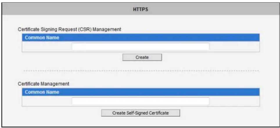
There are two methods to create certificates – Certificate Signing Request (CSR) and Self-Signed Certificate.
text_image
HTTPS Certificate Signing Request (CSR) Management Common Name Create Certificate Management Common Name Create Self-Signed CertificateCertificate Signing Request (CSR): User uses a signed certificate issued by trusted Certification Authority (CA).
Self-Signed Certificate: User wants to use the certificate created and issued by user himself.
Press Create or Create Self-Signed Certificate button and configure settings in the pop-up screen to install the certificate.
Note that the new setting will only take effect after Save & Reboot.
IEEE 802.1X
IEEE 802.1X
IEEE 802.1X is an IEEE standard for port-based Network Access
Control. 802.1X authentication involves three parties: a supplicant, an authenticator, and an authentication server.
The supplicant is a client device (such as an IP camera) that wishes to attach to the LAN/WLAN. The authenticator is a network device, such as an Ethernet switch or wireless access point; and the authentication server is typically a host running software supporting the RADIUS and EAP protocols.
The authenticator acts like a security guard to a protected network. The supplicant (i.e., client device) is not allowed access through the authenticator to the protected side of the network until the supplicant's identity has been validated and authorized. An analogy to this is providing a valid passport at an airport before being allowed to pass through security to the terminal. With 802.1X port-based authentication, the supplicant provides credentials, such as user name / password or digital certificate, to the authenticator, and the authenticator forwards the credentials to the authentication server for verification. If the authentication server determines the credentials are valid, the supplicant (client device) is allowed to access resources located on the protected side of the network.
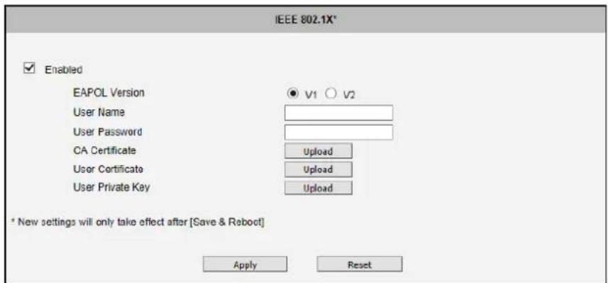
Please enable IEEE 802.1x and configure settings on the screen below. Note that the new setting will only take effect after "Save & Reboot".
text_image
IEEE 802.1X* Enabled EAPOL Version User Name User Password CA Certificate User Certificate User Private Key V1 V2 Upload Upload Upload * New settings will only take effect after [Save & Reboot] Apply ResetEAPOL Version V1 and V2 are the 802.1X communication types. User name and User password area created by user and set in RADIUS server. Certificates and Private Key are provided by RADIUS Server.
If certificates or private key exist already, there will be a Remove button behind these items, in order to remove these items when necessary.
After changing any of the items above, press Apply to save the changes. The Reset button undoes the changes that had just been made but not Applied yet.
SNMP Setting
SNMP Setting
The SNMP Setting item displays the SNMP configuration page.
SNMP provides an easy way to manage network devices. The main features are:
- Monitoring device uptime
- System detail description. (Ex: model name, model description and firmware version.)
- Collect interface information. (Ex: MAC address, interface speed, local port.)
- Measuring network interface throughput.
To use SNMP, just enable SNMP function in the camera (SNMP agents) and run SNMP management software in server (NMS: Network Management Station) to connect to the devices.
SNMP Setting
Enabled
SNMP V1 / V2
V1 Enabled
V2 Enabled
Read Community
public
Write Community
write
SNMP V3
Security Name
public
Password
Must longer than 8 characters
Trap Enabled
Apply
Reset
The SNMP agent supports versions V1, V2 and V3. SNMP V1 is the initial implementation of SNMP. SNMP V2 is proposed to enhance the performance of management, such as the communication of server and devices, the confirmation of information delivery and receipt. Primary additions in SNMP V3 concern security and remote configuration enhancements.
SNMP V1/V2 uses "Community" name as password to authenticate identity. "Read Community" is the password for server to get information from devices. "Write Community" is the password for server to edit values on devices. The default is "public" for Read Community and "write" for Write Community. Of course, you can set any other password as your read/write community.
You can enable V1, V2 or both. Click "Apply" after you've completed setup.
The security method of SNMP V3 uses account/password for authentication. "Security Name" is the account name to be used with your "Password". The default security name is "public" and the password must be at least 8 characters long. You also can set any other security name or password. Click "Apply" after you've completed setup.
SNMP function is now enabled. You may now install and run the SNMP management software on computer server.
SNMP Trap Usage:

text_image
Trap Enabled Destination IP address Trap Community public Available Traps Cold Start Warm Start Authentication Failure Apply ResetSNMP traps enable notifications from devices. Devices may send message to the management server whenever significant events occur such as cold start, warm start and authentication failure. The manager will get the information immediately and take action if necessary.
Cold start means device reboot by power disconnection. Warm start means device reboot by firmware without power disconnection. If there other parties attempt to connect to the device with wrong security password under SNMP V1, V2 or V3 setting, the device will send an authentication failure message to the management server.
To enable SNMP Trap function in the camera, type the IP address of the computer running the SNMP management software and type trap community as password to allow server to get trap message from device (Default is public). Select available traps and click "Apply".
Camera's SNMP offers following information:
| Group | Description |
| System | Provide general information about the managed device.Ex: system description, system name. |
| Interface | Provide general information from the physical interfaces.Ex: interface speed, MAC address. |
| Address Translation | Provide information about the mapping between network addresses and physical addresses for each physical interfaceEx: The IP/MAC addresses to connect to the managed device. |
| IP | Provide the status and operation of Network Layer (Layer 3).Ex: the information and traffic flow of received/delivered package. |
| ICMP | Provide the status and statistics of ICMP.Ex: amount of receive/error message of ICMP. |
| TCP | Provide the status and operation of Transport Layer (Layer 4) using TCP protocol.Ex: TCP Local Port, incoming/outgoing TCP segments. |
| UDP | Provide the status and operation of Transport Layer (Layer 4) using UDP protocol.Ex: UDP Local Port, in/out datagram. |
| SNMP | Provide the related statistics through SNMP |
RTP
RTP
The RTP section allows user to configure RTP Settings.
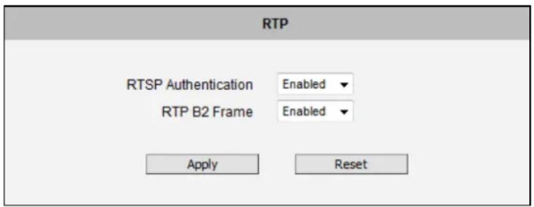
If the RTSP Authentication is "Enabled", then the RTP streaming will require account name and password authentication.
If the RTP B2 Frame is “Enabled” then the B2 frame is added to every video frame, containing additional information, such as motion detection status on each frame, digital input and digital output levels, passive infrared status, other video intelligence data, frame counter, frame-rate mode and the frame-rate, bitrate, resolution, timestamp and much more. The user side can operate with video data easily, including event management, storage consumption estimation, image resizing for preview, etc.
text_image
RTP RTSP Authentication Enabled RTP B2 Frame Enabled Apply ResetAfter changing any of the items above, press Apply to save the changes. The Reset button undoes the changes that had just been made but not Applied yet.
Network (ToS, UPnP, Bonjour, ONVIF)
Network
- Type of Service
UPnP - Bonjour
ONVIF
The section Network contains the controls for following functions:
Type of Service
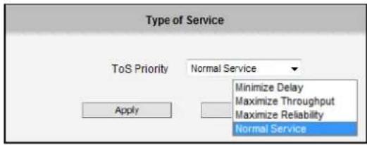
The "Type of Service" provides 4 options to define the priorities of how the data from the camera should be handled by the routers that support ToS concept. By the default, the ToS priority is set as "Normal Service".
text_image
Type of Service ToS Priority Normal Service Minimize Delay Maximize Throughput Maximize Reliability Normal Service ApplyFor special priority arrangement, there are 3 more options:
- Minimize Delay
- Maximize Throughput
- Maximize Reliability
After changing any of the items above, press Apply to save the changes. The Reset button undoes the changes that had just been made but not Applied yet.
UPnP™
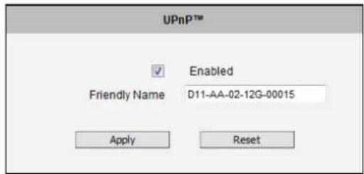
The section UPnP ^TM provides the option to enable or disable the Universal Plug and Play capability of the camera. Having the UPnP ^TM enabled allows the other network devices to seamlessly discover it on the network for convenient identification and access.
text_image
UPnP™ Enabled Friendly Name D11-AA-02-12G-00015 Apply ResetThe Friendly Name is a human-readable name for the device that will be displayed when the camera is found. By default, the serial number of the camera is used as a friendly name; however, the user can modify the name according to the project needs.
After changing any of the items above, press Apply to save the changes. The Reset button undoes the changes that had just been made but not Applied yet.
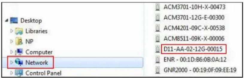
Most of the Windows-based computers have the capability to discover the devices that support UPnP™. Below is the example of Windows 7: by clicking on the Network icon of Windows 7, the PC will discover the cameras instantly.
text_image
Desktop Libraries NP Computer Network Control Panel ACM3701-10H-X-00473 ACM3701-12G-E-00300 ACM4201-09C-X-00538 ACM8511-09K-X-00006 D11-AA-02-12G-00015 ENR - 00:1D:B6:0B:0A:12 GNR2000 - 00:19:0F:09:EE:19Bonjour
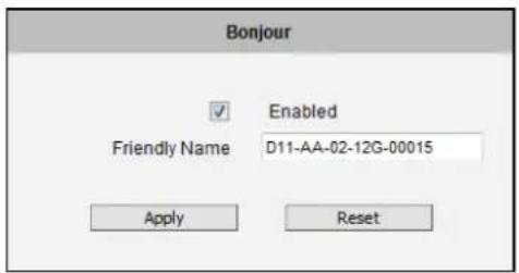
The section Bonjour provides the option to enable or disable the ability of the camera to be discovered by the other network devices using Bonjour protocol, developed by Apple Inc. Both Bonjour and UPnP serve the similar purpose – to discover devices conveniently.
text_image
Bonjour Enabled Friendly Name D11-AA-02-12G-00015 Apply ResetSimilarly to UPnP, the human readable Friendly Name can be defined by the user. That name will be displayed when the camera is found in the network. By default, the Friendly Name is the serial number of the camera; however, the user can modify the name according to the project needs.
After changing any of the items above, press Apply to save the changes. The Reset button undoes the changes that had just been made but not Applied yet.
ONVIF
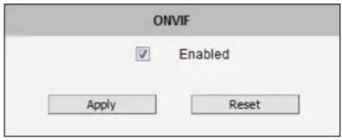
The camera with given firmware is ONVIF 2.2 compliant. By default, the ONVIF function is enabled.
To disable the ONVIF support, remove the check on the box and press Apply.
text_image
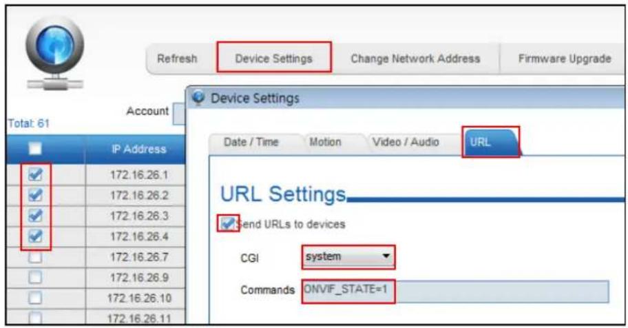
ONVIF Enabled Apply ResetIf you need to activate ONVIF on multiple cameras conveniently, you may use the IP Utility instead, using system cgi and ONVIF_STATE=1 as URL command.
text_image
Refresh Device Settings Change Network Address Firmware Upgrade Device Settings Total: 61 Account IP Address 172.16.26.1 172.16.26.2 172.16.26.3 172.16.26.4 172.16.26.7 172.16.26.9 172.16.26.10 172.16.26.11 Date / Time Motion Video / Audio URL URL Settings Send URLs to devices CGI system Commands ONVIF_STATE=1IP Settings
IP Settings
The section IP Settings provides the options to define how the
camera would obtain its IP address; and to which DNS server should the camera connect to, in order to resolve domain names.
Connection Type
Connection Type
The sub-section Connection Type allows defining the method of
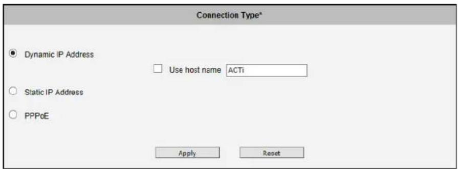
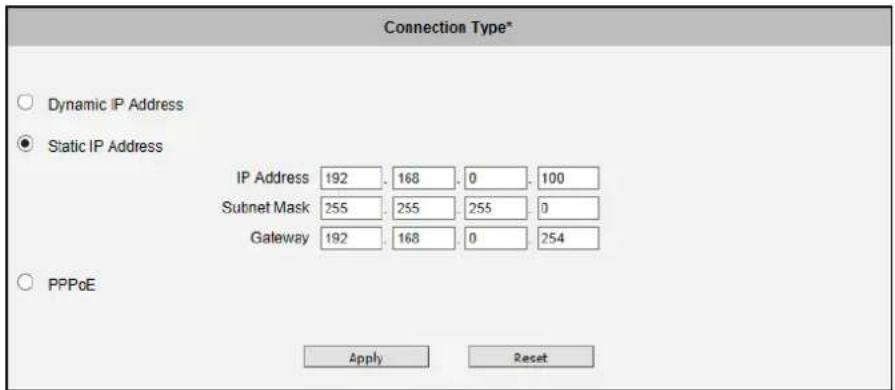
obtaining the IP address of the camera. By default, the camera is in Dynamic IP Address mode and attempts to get the IP address from a DHCP server. If such attempt fails after several seconds (for example the DHCP server does not exist), the camera will automatically assign itself an IP address, listed under Static IP Address.
text_image
Connection Type* Dynamic IP Address Use host name ACTi Static IP Address PPPoE Apply ResetHost Name is used to identify the camera by a DHCP server. In some networks with very strict security policy, it is required that all the network devices should have their host name, and when the devices attempt to access the network by requesting an IP address from a DHCP server, the DHCP server would check if the host name is among the allowed devices. On this page, it is possible to edit the Host Name and enable or disable the use of host name.
text_image
Connection Type* Dynamic IP Address Static IP Address IP Address 192 168 0 100 Subnet Mask 255 255 255 0 Gateway 192 168 0 254 PPPoE Apply ResetMost installation projects include clear network topology and static IP addresses for each camera. In such cases, you can change the camera to Static IP Address mode and modify the IP Address, Subnet Mask and Gateway accordingly.
text_image
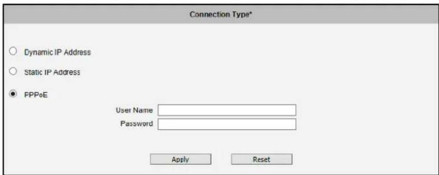
Connection Type* Dynamic IP Address Static IP Address PPPoE User Name Password Apply ResetIn some rare cases, the camera may be connected to the control center over Internet. Usually, the most cost efficient way is to use ADSL connection with PPPoE. To avoid the unexpected changes of IP addresses by Internet Service Provider upon the restart of the camera, it is recommended to activate a DDNS service for such scenario, and let the control center connect to the camera by the domain name instead. Please refer to the DDNS section for more details.
To set the camera in PPPoE mode, set the radio button to PPPoE and key in the User Name and Password, provided by Internet Service Provider.
After changing any of the items above, press Apply to save the changes. The Reset button undoes the changes that had just been made but not Applied yet.
New IP address settings will only take effect after pressing System -> Save & Reboot.
DNS
DNS
The section DNS allows setting up the Domain Name Service for
the camera. The camera will connect to the DNS server when there is a need to resolve a domain name for sending data to.
The most common usage is the ftp or e-mail server in the Event Handler section is defined by using domain names. Without having DNS service configured, the camera would not know how to resolve the domain names of FTP or e-mail servers.
It is possible to configure both Primary and Secondary DNS servers. The Secondary DNS Server will be used when the connection to the Primary DNS Server fails.
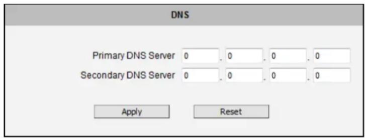
text_image
DNS Primary DNS Server 0 . 0 . 0 . 0 Secondary DNS Server 0 . 0 . 0 . 0 Apply ResetAfter changing any of the items above, press Apply to save the changes. The Reset button undoes the changes that had just been made but not Applied yet.
DDNS
DDNS
There are surveillance solutions that consist of single
cameras scattered over a wide territory, therefore each of those cameras should be connected to the Internet in order to become accessible by Control Center. For example, the chain stores, bus stops, currency exchange booths, etc.
In such cases, one of the practical networking solutions is to use DSL modem on camera site and let the camera obtain the dynamic IP address from the Internet Service Provider through the DSL modem using PPPoE connection, which is much more cost-effective than applying for static IP address.
PPPoE Connection with Dynamic IP address
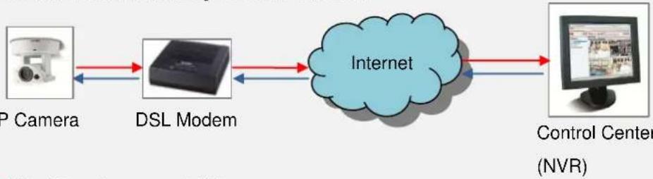
flowchart
graph LR
    A["P Camera"] --> B["DSL Modem"]
    B --> C["Internet"]
    C --> D["Control Center (NVR)"]
    style C fill:#cce5ff,stroke:#333
→ Video Stream from camera to NVR
→ Commands from NVR to camera's IP address
However, there is one drawback in this solution – in order to do the remote surveillance from the Control Center, the NVR Server in the Control Center has to know the address of the IP camera at all times in order to get the video stream from the camera. If the camera's network connection has been reset for any reason, the camera will get a new IP address through DSL Modem, which may be different from the previous one. NVR will not know about this change, and the connection between the camera and NVR will fail.
There however exists a solution that makes sure the NVR can find the camera even if the camera IP changes frequently. Our cameras support Dynamic DNS or DDNS service that allows frequently changing IP be mapped to a certain unchangeable domain name. The mapping database and its updating engine are hosted in one of the Dynamic DNS servers, most of which offer basic services for free, such as www.dyndns.org.
How does it work? Look at the graph below.
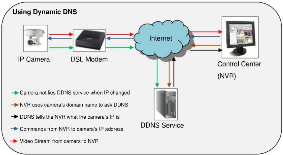
flowchart
graph TD
    A["IP Camera"] --> B["DSL Modem"]
    B --> C["Internet"]
    C --> D["Control Center (NVR)"]
    D --> E["DDNS Service"]
    E --> F["Video Stream from camera to NVR"]
    F --> C
    style A fill:#f9f,stroke:#333
    style B fill:#f9f,stroke:#333
    style C fill:#ccf,stroke:#333
    style D fill:#ccf,stroke:#333
    style E fill:#cfc,stroke:#333
    style F fill:#fcc,stroke:#333
Every time the IP camera gets an IP that is different from previous one, it notifies the public DDNS Service about the change. The DDNS Service updates its database immediately, mapping the assigned domain name (for example camera123.dyndns.org) to the new IP address. In NVR settings, only the domain name (camera123.dyndns.org) is used to identify the camera. Every time when NVR needs to connect to the camera, it asks from DDNS Service what the current camera's IP is. The DDNS Service instantly responds to NVR and tells it the camera's IP. Now NVR will use the IP of the camera to connect to the camera and the video stream from the camera to NVR can be initiated.
As a result, NVR can always find the IP camera regardless of frequently changing IP address of the camera. Since there are so many public DDNS Services available for free, the PPPoE-based connection is really a good and low-cost solution for single-camera sites.
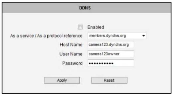
text_image
DDNS Enabled As a service / As a protocol reference members.dyndns.org Host Name camera123.dyndns.org User Name camera123owner Password ••••••••••• Apply ResetTo activate DDNS, please check the "Enabled". Select the service reference, input the Host Name (the domain name given to the camera by DDNS service, User Name and Password of the DDNS server account.
You will get the needed Host Name, User Name and Password information from the DDNS service provider once you have registered an account there and requested a domain name for your camera.
After changing any of the items above, press Apply to save the changes. The Reset button undoes the changes that had just been made but not Applied yet.
Video & Audio
+ Video
The section Video or Video & Audio (for audio supported cameras)
provides the options to adjust the video quality, configure the streaming details of the camera, and audio settings (for Audio supported cameras only), which will be described in the succeeding pages.
The default settings of the camera are sufficient for most environments and the video adjustments are not necessary. The following sections explain the ways to configure the video quality or streaming details in case it is required to do so.
The [+] mark before Video indicates that the list can be expanded by clicking on it. Once expanded, the list can later be collapsed again by clicking on the [-] mark.
Camera Options
Camera Options
In general, the Camera Options submenu allows users to set the
Line Frequency and Stream Mode properties of the camera. Depending on the camera type, the parameters on the Camera Options screen vary.
text_image
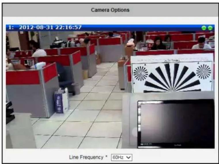
Camera Options 1: 2012-08-31 22:16:57 Line Frequency * 60HzLine Frequency is the function that adjusts the shutter speed options to match with the frequency of artificial light source of given country. For example, in Europe the light frequency (due to power supply frequency of lights) is 50Hz, that is 50 flashes per second. By setting line frequency to 50Hz in such case, the shutter speed options will be proportional with light source frequency, such as 1/25s, 1/50s, 1/100s, etc.
It is necessary to have the camera's Line Frequency adjusted according to the power frequency of the light source to avoid flickering effect.
The natural light source (sun light) is a seamless flow of light – the Line Frequency setting does not matter for the cameras that are only exposed to natural light.
Camera Options of 1.3MP Cameras
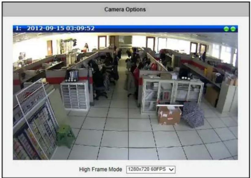
Cameras with 1.3MP resolution have a high frame rate mode of 60fps. By default, high frame mode is disabled. To enable this feature, select the maximum resolution and frame rate on High Frame Mode, some video settings such as Exposure and White Balance, etc. will be automatically configured. This configuration will automatically be set as the video stream 1 and the original configuration of stream 1 will now be video Stream 2.
text_image
Camera Options 1: 2012-09-15 03:09:52 High Frame Mode 1280x720 60FPSCamera Options of Fisheye and Hemispheric Cameras
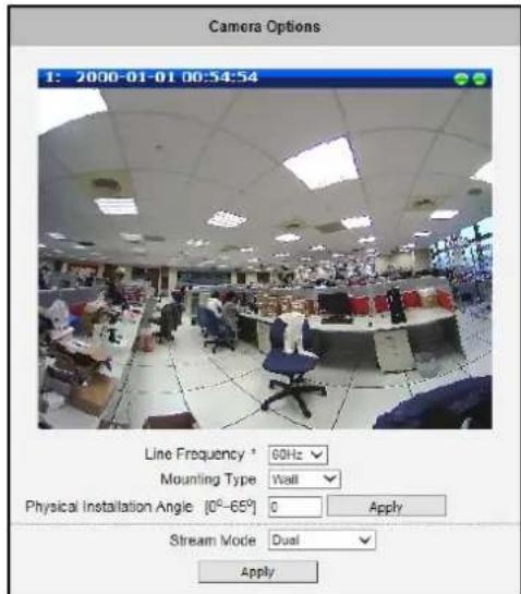
Choose the Mounting Type according to how the camera is mounted to display the appropriate view. There are three options: Wall, Ceiling or Ground.
For Wall mount, a single panorama view is shown. Adjust the Physical Installation Angle to do proper dewarping based on the newly defined center of the view.
NOTE: Physical Installation Angle for Hemispheric camera models is available only if the Stream Mode is Dual, see Stream Mode: Dual on page 60 for more information. Stream mode is available on Hemispheric camera models only.
text_image
Camera Options 1: 2000-01-01 00:54:54 Line Frequency * 00Hz Mounting Type Wall Physical Installation Angle [0°-65°] 0 Apply Stream Mode Dual Apply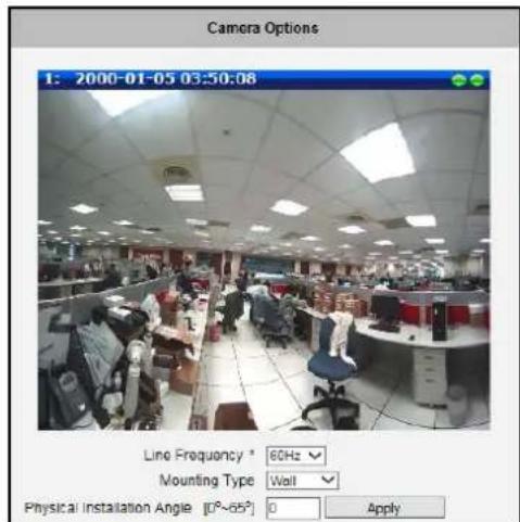
text_image
Camera Options 1: 2000-01-05 03:50:06 Line Frequency * 60Hz Mounting Type Wall Physical Installation Angle [0°~65°] 0 ApplyExample of Hemispheric Camera Example of Fisheye Camera
| Type | Description | Physical Installation Angle |
 | Not using the 10° Titled Wall Mount | 0 degree |
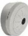 | With 10° Tilted Wall Mount | 10 degree |
After changing any of the items above, press Apply to save the changes.
Select Ceiling mount if the camera is installed on the ceiling. A double panorama is shown on the window, showing the upper and lower hemisphere of the video.
Select Ground mount if the camera is installed on a flat surface, like on the ground or on a table top with the camera facing up. A double panorama is shown on the window, showing the upper and lower hemisphere of the video.
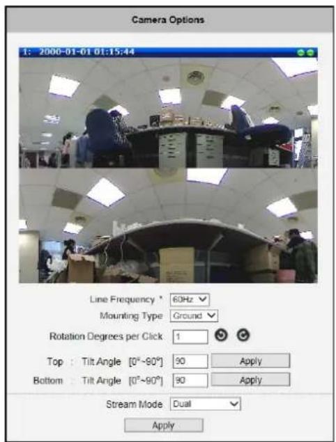
text_image
Camera Options 1: 2000-01-01 01:15:44 Line Frequency * 60Hz Mounting Type Ground Rotation Degrees per Click 1 Top : Tilt Angle [0°~90°] 90 Apply Bottom : Tilt Angle [0°~90°] 90 Apply Stream Mode Dual Apply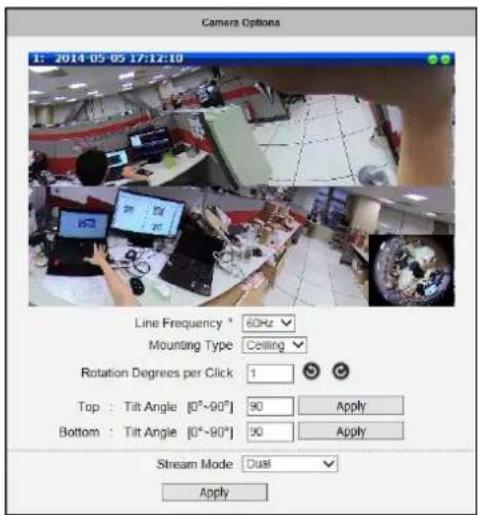
text_image
Camera Options 1: 2014-05-05 17:12:10 Line Frequency * 60Hz Mounting Type Ceiling Rotation Degrees per Click 1 Top : Tilt Angle [0°~90°] 90 Apply Bottom : Tilt Angle [0°~90°] 90 Apply Stream Mode Dual ApplyCeiling Mounting Type Ground Mounting Type
| Parameters | Description |
| Ceiling or Ground Mounting Type | |
| Rotation Degrees per Click | This function allows users to specify a rotation angle and rotates the both the top and bottom panorama views when the rotate icons are clicked. The original fisheye view remains the same. |
| Top: Tilt Angle [0°~90°] | Specify the tilt angle of the top panorama view, then clickApplyto tilt the viewing angle. By default, the tilt angle is set at 90. |
| Bottom: Tilt Angle [0°~90°] | Specify the tilt angle of the bottom panorama view, then clickApplyto tilt the viewing angle. By default, the tilt angle is set at 90. |
After changing any of the items above, press Apply to save the changes.
Stream Mode: Dual (for Hemispheric Cameras only)
The Dual view mode of the Hemispheric cameras simply streams a 180° panaroma view for cameras mounted on the wall, in this case, the Mounting Type must be set to Wall. If the Mounting Type is set as Ceiling or Ground, the video is streamed with a 360° panorama view.
Stream Mode: ePTZ (for Hemispheric Cameras only)
The ePTZ mode of Hemispheric Cameras works in similar way as optical PTZ function in Speed Domes. As the camera receives commands from remote client, it changes the direction of the view or zooms in or out digitally. The stream coming out from the camera represents the current viewing direction of the camera, not the panoramic view.

text_image
Web ConfiguratorIf you are using hemispheric camera in ePTZ mode, this screen is available by clicking on ePTZ button in the live view screen. Mouse PTZ is enabled at the same time.
You can configure up to 32 Zoom presets below. Just click Set, enter the name and move position to what you desire, then click set again. You can instantly ask the camera to go to that zoom and focus position by clicking on the Goto button.
Click Delete to remove this zoom preset point from camera memory.
You can use ePTZ in live view by moving the mouse over video and clicking on the video anywhere you like. Wherever you click, that point will become new "center" of the view. This is how you "pan" and "tilt". You also can rotate the view via PTZ panel if you like.
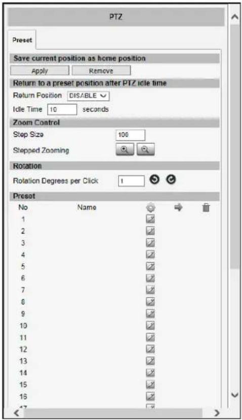
text_image
PTZ Preset Save current position as home position Apply Remove Return to a preset position after PTZ idle time Return Position DISABLE Idle Time 10 seconds Zoom Control Step Size 100 Stepped Zooming Rotation Rotation Degrees per Click 1 Preset No Name → ✓ 1 ✓ 2 ✓ 3 ✓ 4 ✓ 5 ✓ 6 ✓ 7 ✓ 8 ✓ 9 ✓ 10 ✓ 11 ✓ 12 ✓ 13 ✓ 14 ✓ 15 ✓ 16 ✓ 17 ✓To zoom in or out under ePTZ mode, use the scroll wheel of the mouse

natural_image
Close-up of a beige computer mouse with a red square highlighting the interior (no text or symbols visible)Preset Tour
After you set the Preset Point, the Tour function will be enabled. See How to Set Preset Points on page 26 for more information.
NOTE: Home position has to be set again after changing the installation type, the motion detection configurations and PTZ configurations like preset points.
Stream Mode: Fisheye View (for Hemispheric Cameras only)
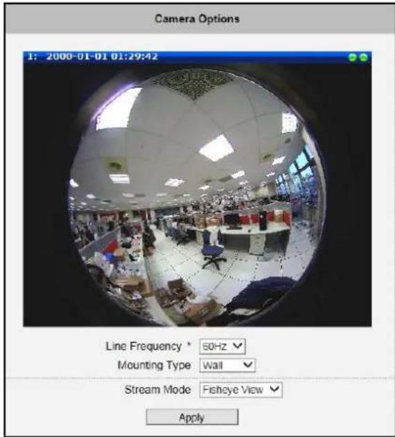
The Fisheye View mode shows the camera view as though viewing from a fish's eye with the whole viewing angle in sight but details may be too small and not be seen clearly.
text_image
Camera Options 1: 2000-01-01 01:29:42 Line Frequency * 60Hz Mounting Type Wall Stream Mode Fisheye View ApplyCamera Calibration
Camera Calibration
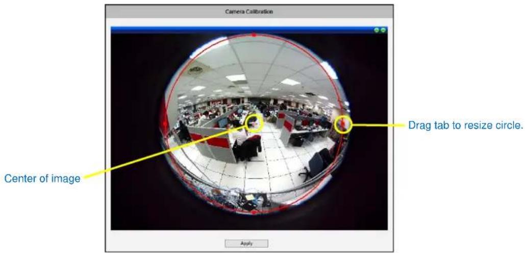
Camera Calibration allows users to manually calibrate and find the center image of the camera. Since the camera has already been calibrated before shipment, calibrating the camera is not usually needed. However, if the image will be flipped through Vi
Flipping / Video Mirroring function (see Image on page 72), then the camera must be recalibrated.
text_image
Camera Calibration Center of image Drag tab to resize circle. ApplyMove the mouse cursor within the red circle and drag towards the target area you want to cover.
The radius of the circle may also be resized by dragging one of the square tabs.
Press Apply to save the changes.
Video
Video
The sub-section is also named Video. For Audio supported cameras,
there will also be a sub-section named Audio. The video section is divided into tabs. The functionality of each tab is explained separately below.
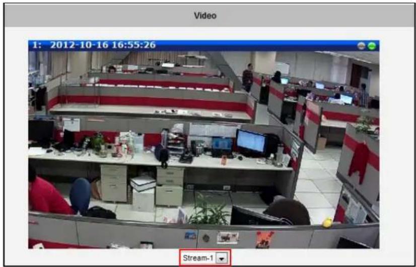
Upon opening the sub-section named Video, the live view of the Stream 1 of the camera will appear. Since the camera is a dual stream device, it is possible to see how each of the 2 streaming configurations looks like, by selecting either Stream-1 or Stream-2 under the live video window.
text_image
Video 1: 2012-10-16 16:55:26 Stream-1Usually, Stream-1 is configured to be high quality video with maximum resolution and frame rate for recording purposes while Stream-2 is usually a moderate quality stream for live view purposes of the VMS, to reduce VMS computing power during video decoding of multiple channels.
Compression
Compression
The section "Compression" allows the user to define the compression settings of the video stream 1 and stream 2. The purpose of compression is to reduce the bandwidth and VMS storage consumption.
Usually the stream 1 is configured to be the best quality stream for NVR recording purposes while the stream 2 is configured to be with the basic quality for the live view of NVR, to minimize the computing power of NVR used for video decoding.
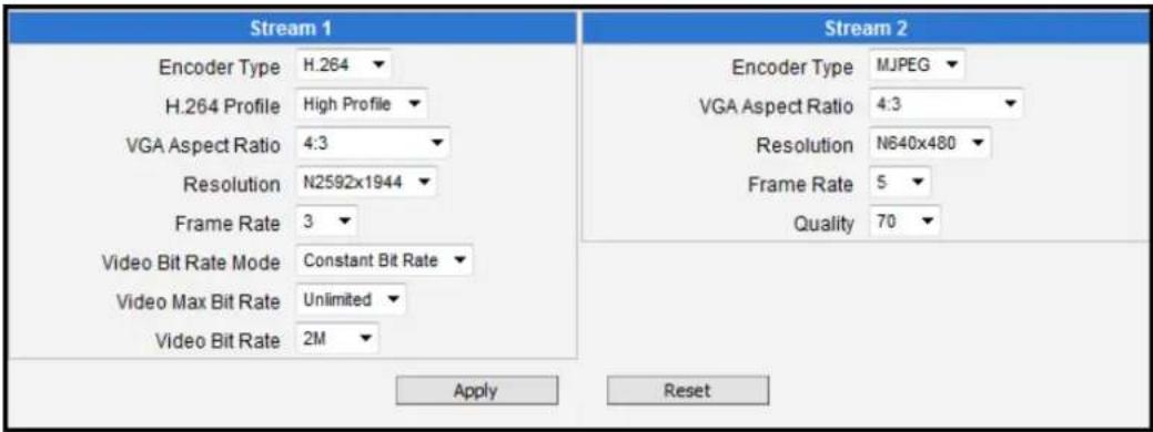
text_image
Stream 1 Encoder Type H.264 H.264 Profile High Profile VGA Aspect Ratio 4:3 Resolution N2592x1944 Frame Rate 3 Video Bit Rate Mode Constant Bit Rate Video Max Bit Rate Unlimited Video Bit Rate 2M Stream 2 Encoder Type MJPEG VGA Aspect Ratio 4:3 Resolution N640x480 Frame Rate 5 Quality 70 Apply Reset| Parameters | Description |
| Encoder Type | There are two encoder types available: H.264 (High Profile) and MJPEG. |
| H.264 Profile | This item is available only if the Encoder Type is H.264.The H.264 Profile defines the video compression scheme:High Profile, Main Profile, and Baseline. These schemes vary from least compressed,Baseline, to most compressed,High Profile. By default, the H.264 Profile isHigh Profile, which provides the most compression with the best video quality, but more computing power. Some third-party video management system has longer latency or takes more time to decode High Profile compression scheme, in this case, you can selectMain Profileor Baseline. In order to get the same video quality, you can select a higher bit rate with lower compression; this is the same as having a lower bit rate with a High Profile. For example, a video on High Profile with 2M bit rate will have the same video quality as a video with Baseline Profile at 3.5M bit rate. |
| VGA Aspect Ratio | It is used to define the aspect ratio of VGA stream – it can be either 4:3 ratio (640x480) or 16:9 ratio (640x360). When “Auto Detected” is chosen, the VGA stream will follow the ratio of the higher resolution stream, to ensure the identical view of stream 1 and stream 2. |
| Resolution | Depending on the camera model, the number of available resolutions may be different. The default resolution setting of the camera may not necessarily be the maximum resolution of the camera. If the user wants to use the maximum resolution, it is possible to do it here. The maximum possible resolution of the stream 2 will be smaller than stream 1. |
| Frame Rate | Defines the amount of frames per second. |
| Video Bit Rate Mode(only for H.264) | Under “Constant Bit Rate” mode (CBR), the camera keeps the stable bitrate regardless of the complexity of the scene. Under this mode, the video quality may vary if the bit rate value is set too low. It is easier to do storage and network bandwidth consumption estimations under this mode compared to Variable Bit Rate mode.Under “Variable Bit Rate” mode (VBR), the camera will keep the video quality stable while the bit rate may occasionally go up or down, depending on the complexity of the scene. |
| Video Max Bit Rate(only for H.264) | Defines the upper limit of the bitrate (only available under CBR mode). The bitrate will be floating slightly under that limit. For example, if the limit is set as 2M, the bitrate will be floating around 1.6~2.0 Mbps.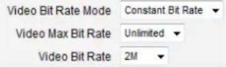 If the Video Max Bit Rate is chosen as “Unlimited”, then the “Video Bit Rate” selection box will appear that defines the bit rate level. If the Video Max Bit Rate is chosen as “Unlimited”, then the “Video Bit Rate” selection box will appear that defines the bit rate level. |
| Video Bit Rate(only for H.264) | Under CBR mode, when Video Max Bit Rate is chosen “Unlimited”, the user can define the AVERAGE bit rate. For example, if the Video Bit Rate is chosen 2M, then occasionally, the actual bit rate may go below or beyond 2M, but in the long run, the average bit rate will be very close to 2M. This mode allows the most accurate storage estimations, however, while planning the bandwidth, please consider the occasional peaks of bit rate. |
| Quality | H.264 Compression: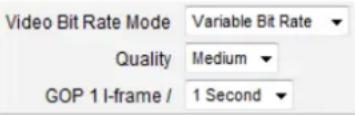 Under VBR mode, the bit rate will be floating while the video quality will be stable and follows the quality standard set by the user. The user can choose either “High”, “Medium” or “Low” quality. The higher is the quality level, the more bit rate the camera will use to achieve the target quality.MJPEG Compression:The user can define the quality with the numeric scale from 1 to 100. The default MJPEG quality is 60. The higher is the quality level, the more bit rate the camera will use to achieve the target quality. Under VBR mode, the bit rate will be floating while the video quality will be stable and follows the quality standard set by the user. The user can choose either “High”, “Medium” or “Low” quality. The higher is the quality level, the more bit rate the camera will use to achieve the target quality.MJPEG Compression:The user can define the quality with the numeric scale from 1 to 100. The default MJPEG quality is 60. The higher is the quality level, the more bit rate the camera will use to achieve the target quality. |
| GOP(only for H.264) | Under VBR mode it is possible to adjust the GOP length - that is the occurrence rate of I-frames. By default, there is one I-frame per second. For example, in case of 30fps, there will be 1 I-frame and 29 P-frames every second by default. When the GOP is changed to “1 I-frame per 5 seconds”, then there will be one I-frame, followed by 149 P-frames. In case of the static scenes, long GOP can further minimize the bandwidth and storage consumption. |
After changing any of the items above, press Apply to save the changes. The Reset button undoes the changes that had just been made but not Applied yet.
Motion Detection
Motion Detection
The section "Motion Detection" allows the user to configure the video motion detection system of the camera. Motion detection regions are based on Stream 1. By default, there are three (3) enabled pre-defined regions covering the whole camera view.
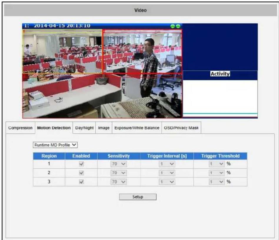
text_image
Video 1: 2014-04-15 20:13:10 Activity Compression Motion Detection Day/Night Xi Image Exposure/White Balance OSD/Privacy Mask Runtime MD Profile Region Enabled Sensitivity Trigger Interval [s] Trigger Threshold 1 ✓ 70 ✓ 1 ✓ 1 ✓ % 2 ✓ 70 ✓ 1 ✓ 1 ✓ % 3 ✓ 70 ✓ 1 ✓ 1 ✓ % SetupClick on "Setup" to adjust the motion detection regions or its parameters. Microsoft Internet Explorer browser is required to configure the motion detection regions.
There are three independently configurable motion detection regions in the camera. Each motion detection region has 6 configuration parameters:
- Enabled or disabled
- Location of the region
- Size of the region
- Sensitivity
- Trigger threshold
- Trigger interval
Enabled or disabled
Although all 3 motion detection regions are enabled by default, each can be disabled and enabled individually. Look at the example: Only the region 1 is enabled while 2 and 3 are disabled. The disabled regions disappear from the video display.
Note that the number of the motion detection region is written in the upper left corner of the region.
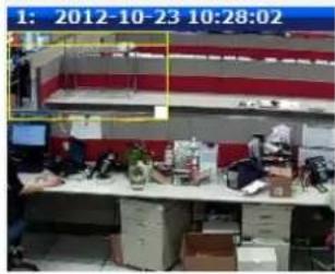
text_image
1: 2012-10-23 10:28:02| Region | Enabled | Sensitivity |
| 1 | 70▼ | |
| 2 | 70▼ | |
| 3 | 70▼ |
Location of the region
You can move the motion detection region anywhere on the field of view by dragging the top of the motion detection rectangle as shown on the image. The motion detection regions may even be overlapping if you like.
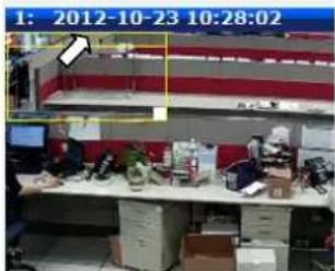
text_image
1: 2012-10-23 10:28:02Size of the region
By dragging the lower right corner of the motion detection region you can change the size of the region. The maximum size of the region can even be as big as the whole screen.
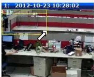
text_image
1: 2012-10-23 10:28:02Sensitivity
Sensitivity is the parameter that helps us distinguish actual moving targets (people, vehicles) from the slightly moving background, such as leaves of the trees waving in the wind. In order to avoid false alarms, we might want the camera be able to ignore small motion. The higher is the sensitivity level of the camera the smaller shift of the object is needed to trigger the alarm. For example, if the object within motion detection region has moved for about 1-3 pixels during two video frames, then such small motion will be discarded by camera if the sensitivity is low, and will still trigger an alarm if the sensitivity is high. In other words, you can think of sensitivity level as a reversed speed limit – the smaller is the sensitivity, the faster are the objects allowed to move without being detected.
The biggest challenge of motion detection configuration is to find the settings that do not produce false alarms and at the same time do not miss any actual intrusions. The rule of thumb is: the sensitivity should be as high as possible while not producing false alarms. The default sensitivity level of the cameras is 70 (on a scale of 0-100) and it is a good setting for most standard cases.
Trigger threshold
Look at the moving object entering the area of motion detection: although moving quite slowly, it caused motion activity – several pixel regions reported a motion that was faster than allowed “speed limit” of sensitivity (70).
The blue graph on the right side of the image shows how many percent of pixels within the motion detection
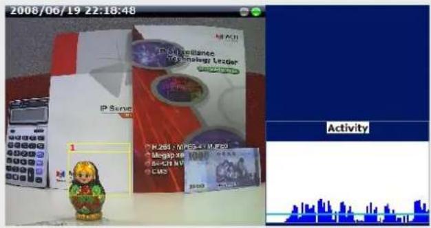
text_image
2008/06/19 22:18:48 IP SANPA IP SANPA 1 Activity| Runtime ND Profile | ||||
| Region | Enabled | Sensitivity | Trigger Interval [s] | Trigger Threshold |
| 1 | 70▼ | 1▼ | 10▼% | |
| 2 | 70▼ | 1▼ | 10▼% | |
| 3 | 70▼ | 1▼ | 10▼% | |
region were considered as “currently in motion”. The activity panel itself is a timeline – for each moment of time you can see the height of the blue bars. You may notice that at certain moment the tallest bars in the activity graph reached about 25% (a quarter of the total height in activity panel) – it means, 25% of this motion detection area were filled with moving pixels at that moment. By visual observation you can also see that the object standing inside the motion detection region indeed covers about 25% of its size.
What if the object is really small but moves rather fast (gets triggered by the current sensitivity level)? For example, we want to detect people but not the cat walking in the room. Although both people and cat may move with the speed that will trigger motion, they have different size of triggered pixels. For example, a human passing by the motion detection region will trigger 25% of pixels in that region while the cat would trigger only 2%. Since we want to have a real alarm in case of human or vehicle passing by while ignoring birds, cats, butterflies, mice, etc, we need a filter that can define how many percent of triggered pixels will be considered as a real alarm. This parameter is called trigger threshold. The default value of trigger threshold is 10%. It means, only the objects that are bigger than 10% of the motion detection region size and move faster than allowed by sensitivity level (70) will produce actual alarm.
How to choose the most optimal trigger threshold level? The rule of thumb, keep the trigger threshold as small as possible while not causing false alarms by the moving objects that are not humans or vehicles.
You can have different sensitivity level and trigger threshold level for each motion detection region.
In order to understand all of the above even better, please refer to the table below containing four
possible combinations of settings using sensitivity level and trigger threshold percentage.
The objects listed in each cell will trigger an alarm under given settings:
| Low threshold (0-5%) | High threshold (5-100%) | |
| Low sensitivity(0-65) |  Big and fastSmall and fast Big and fastSmall and fast |  Big and fast Big and fast |
| High sensitivity(65-100) |  Big and fast Big and fast Big and slowSmall and fast Big and slowSmall and fast Small and slow Small and slow |  Big and fast Big and fast Big and slow Big and slow |
The camera's default sensitivity is 70 and threshold is 10% . By these default values, only the rabbit and the turtle would trigger an alarm while the butterfly and the snail would be ignored by the motion detection system.
Important: Please remember that changing the size of the motion detection region has an impact on the threshold – the bigger is the size of the motion detection region the smaller should be the threshold value if you want the same object size to trigger motion. For example, if you increase the motion detection region to twice the previous size, please remember to reduce the threshold to half its original value (from 10% to 5%). On the other hand, changing the location of the motion detection region has no impact on threshold.
Trigger interval
The last configuration item is the trigger interval. It is the time period from the beginning of the triggered event during which the all motion activities are ignored by the camera. This is designed to avoid needless repetitive reporting of the same intrusion. Trigger interval 20 seconds would mean that when the even happens, camera will take certain one-time actions and ignore the continuing activity in the motion detection region for 20 seconds. When 20 seconds are over, the camera will produce a new alarm if there are still action in the motion detection region, and take actions again.
There is one more item on the Motion Detection configuration page which was not explained above – the Profile of Motion Detection. Think of them as Profile 1 (Runtime MD Profile) and Profile 2 (Event MD Profile). It means that you can configure
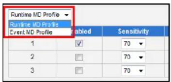
text_image
Runtime MD Profile Runtime MD Profile Event MD Profile Enabled Sensitivity 1 ✓ 70 2 ☐ 70 3 ☐ 70two independent groups of Motion Detection regions with at most 3 regions in each group. Normally, the Profile 1 (Runtime MD Profile) is used as an active profile of the camera. However, in some cases it is possible to let the camera switch to Profile 2 by using the Event Handler system of the camera.
For example, you might want to have different motion detection parameters for day and night time. Then the two profiles become really handy. In such case, remember to configure the motion detection parameters for both profiles before moving on to configure the event response system.
After changing any of the items above, press Apply to save the changes. The Reset button undoes the changes that had just been made but not Applied yet.
NOTE: For PTZ / Speed dome cameras, it is recommended to turn off motion detection when scan and tour modes are enabled to avoid false motion alarm.
Day/Night
The section Day/Night allows user to control the switching between day mode and night mode. This section will be displayed only for day/night models.
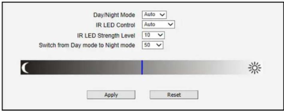
text_image
Day/Night Mode Auto IR LED Control Auto IR LED Strength Level 10 Switch from Day mode to Night mode 50 Apply Reset| Parameters | Description |
| Day/Night mode | There are three modes:Auto: The camera will automatically switch between day mode (color) and night mode (black/white) under certain exposure level, defined by user at “Switch from Day mode to Night mode”.Day: The camera always stays in day mode (color) regardless of exposure level.Night: The camera always stays in night mode (black/white) regardless of exposure level. |
| IR LED Control | This feature is visible only in cameras with built-in IR LED.There are two modes:Auto: The built-in IR LED will be turned on automatically upon day to night switch and turned off upon night to day switch.Disabled: The IR LED will be off regardless of day and night mode.Zoom cameras have adaptive IR profile, which means that when IR LED Control is set to “Auto” (default setting), the IR LED automatically adapts to the required IR LED power as the camera is zoomed in or out. |
| IR LED Strength Level | This feature is visible only in fixed and vari-focal lens cameras with adaptive IR profile and when IR LED Control is set to “Auto”.The scale of 1~10 allows the user to manually define the power level of the IR LED. The higher the value, the brighter the IR LED is. Set the IR LED Strength Level according to the installation environment requirement, or set it to “OFF” to turn off the IR LED. |
| Switch from Day mode to Night mode | The scale of 0~100 allows user define the exposure level at which the day to night switch should happen. The higher is the value, the darker the environment has to be to trigger the day to night switch. |
Image

The section Image allows user to control certain parameters of a video frame.
For D / E / B Series
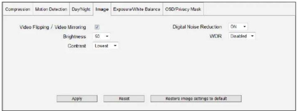
text_image
Compression Motion Detection Day/Night Image Exposure/White Balance OSD/Privacy Mask Video Flipping / Video Mirroring ✓ Brightness 50 Contrast Lowest Digital Noise Reduction ON WDR Disabled Apply Reset Restore image settings to defaultFor I-Series Only
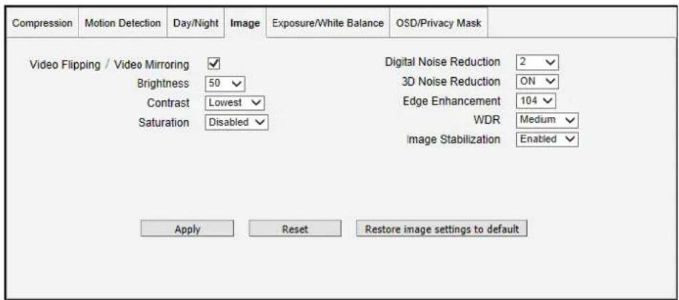
text_image
Compression Motion Detection Day/Night Image Exposure/White Balance OSD/Privacy Mask Video Flipping / Video Mirroring ✓ Brightness 50 Contrast Lowest Saturation Disabled Digital Noise Reduction 2 3D Noise Reduction ON Edge Enhancement 104 WDR Medium Image Stabilization Enabled Apply Reset Restore image settings to default| Parameters | Description |
| Video Flipping / Video Mirroring | Check this box to flip the video up-down and left-right to achieve the 180-degree rotation effect. |
| Brightness | Select the Brightness value (0~100). The higher the value, the brighter the image. |
| Contrast | Select the Contrast level from following options: Lowest, low, medium, high, highest |
| Saturation (for I-series only) | Saturation makes colors appear more vivid. Select the Saturation level from the following options: Disabled, low, medium, high, highest. |
| Digital Noise Reduction | Turn ON or OFF the Digital Noise Reduction. When turned on, the noise on the video (especially in low light) is reduced and image will look smoother and clearer. |
| WDR | Choose the WDR level from following options: Disabled, low, medium, high, highest.NOTE:WDR is disabled and will not appear on screen if Exposure Mode is set to “Manual”. See Exposure / White Balance on page 74. |
| 3D Noise Reduction (for I-series only) | Enable this feature for smooth and clear image. Disable this feature if the scene contains extreme details that may be smoothed over with3DNR. |
| Edge Enhancement (for I-series only) | Select the Edge Enhancement value. The higher the value, the sharper the image. |
| Defogging (for I-series only) | This feature provides a clear image even when the camera is installed in a foggy environment. Select the Defogging level: Disabled, Low, Medium, High, and Highest. Wherein “Low” is ideal for a slightly foggy environment and “Highest” for the foggiest environment.NOTE: After upgrading the camera firmware to V.6.08.30, make sure to update the ISP file which is included in the firmware package file. For more information, refer to the Release Note downloadable from the website. |
| Image Stabilization (for I-series PTZ / Speed Domes only) | This feature has no obvious effect under normal viewing conditions. However, if the camera is installed inside a moving vehicle, such as a train, etc., enable this feature to make the image stable even when the environment is in constant motion. |
After changing any of the items above, press Apply to save the changes. The Reset button undoes the changes that had just been made but not Applied yet.
The button “Restore image settings to default” is a quick way of restoring factory default image settings without needing to reset the whole camera to factory default.
Exposure / White Balance
Exposure/White Balance
The section Exposure / White Balance allows the user to configure
Exposure (shutter, iris and gain control) and White Balance settings. In most cases, the default settings are sufficient and no adjustment is needed. Some options will only appear under certain Exposure / White balance modes. Each mode is described in detail below.
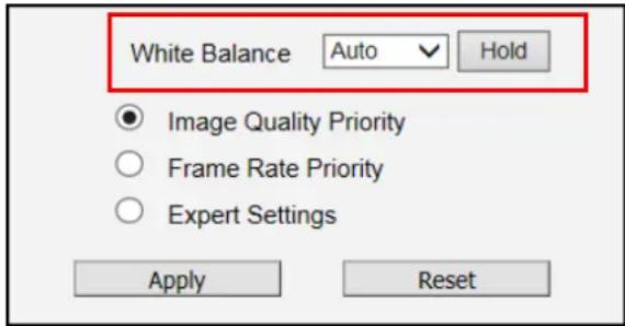
text_image
White Balance Auto Hold Image Quality Priority Frame Rate Priority Expert Settings Apply ResetWhite balance refers to the capability of the camera to understand what “true white color is”. When the camera knows the true white color, then the rest of the colors will be accurate, too. While human eye can easily adapt to different lighting sources (even mixed sources, such as sun light through the window and indoor lights turned on at the same time), the camera has to understand what is the dominant light source in given scene and what is the “white color” of such light source.
By default the camera is in auto white balance mode and attempts to recognize the light source and its color spectrum automatically and adjusts the image accordingly. This function works continuously in the background. It is re-evaluated for each frame, to make sure if there is any change in dominant light source (e.g. the user closes the curtains to block the sun light and turns on the indoor lights).
In most cases the auto white balance works perfectly and the user does not have to adjust anything! In some rare installation cases, especially when there are no white color objects in the field of view, and the light sources are mixed, the camera may have difficulty to identify the true white color to fine tune the rest of the colors.
In such cases, the installer can “help” the camera to understand the true colors by placing a white object (for example a piece of white paper) in front of the camera to cover the whole field of view and wait a few seconds – the auto white balance system will adjust the colors until the white paper will really look white on the display. At that moment, the user can freeze these white balance settings by pressing the Hold button. After pressing that button, the White Balance will switch from Auto mode to Manual mode, together with the color values captured at the moment of
Hold. The user can now remove the white object from the field of view, and the colors will stay correct for given scene.
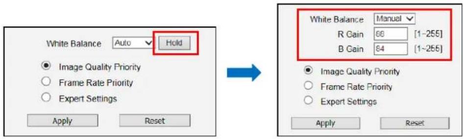
text_image
White Balance Auto Hold Image Quality Priority Frame Rate Priority Expert Settings Apply Reset White Balance Manual R Gain 66 [1-255] B Gain 84 [1-255] Image Quality Priority Frame Rate Priority Expert Settings Apply ResetFor advanced users, there is also an option to switch from Auto mode to Manual mode of White Balance directly and input the R Gain and B Gain values manually.
To simplify exposure settings, the camera firmware sets the "Slowest Auto Shutter Speed" to achieve two exposure control settings, namely:
• Image Quality Priority
• Frame Rage Priority
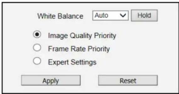
text_image
White Balance Auto Hold Image Quality Priority Frame Rate Priority Expert Settings Apply ResetSelect Image Quality Priority if users want to get a clear image of static objects but accept motion blur for fast moving objects in low light.
Select Frame Rate Priority if users do not want to have motion blur but accept noise on the image in low light.
For advance users, select Expert Settings to display and manually configure the exposure settings.
IR Exposure Compensation – Enabled
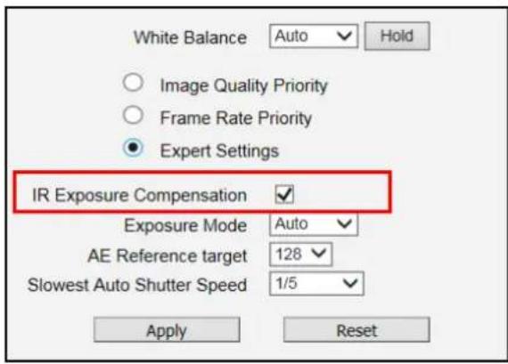
text_image
White Balance Auto Hold Image Quality Priority Frame Rate Priority Expert Settings IR Exposure Compensation ✓ Exposure Mode Auto ✓ AE Reference target 128 ✓ Slowest Auto Shutter Speed 1/5 ✓ Apply ResetIR Exposure Compensation is available on all cameras with IR LEDs. This feature automatically balances the IR exposure to eliminate over-exposed images cause by too much IR on the subject. When enabled, the AE reference target is automatically adjusted to control the sensor's shutter speed and gain to compensate IR effect.
Exposure Mode - Auto
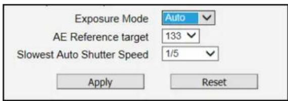
text_image
Exposure Mode Auto AE Reference target 133 Slowest Auto Shutter Speed 1/5 Apply ResetIn Auto Exposure Mode, you control the image brightness by configuring the AE Reference Target and Slowest Auto Shutter.
AE Reference Target (Auto Exposure reference target) can be considered as the "Target Brightness on Sensor". The camera will use several internal parameters to achieve best quality with reference to this. The higher this value, the brighter the overall scene, however, there may be more noise at night in such case. The range of AE Reference Target is 1\~255.
The camera will automatically control shutter speed, auto iris (if available) and signal gain to achieve the target level set by the user. If the auto iris does not exist or is already opened to a maximum size, and the image is still darker than the user defined target, it will further slow down the shutter speed within the allowed range (set by user under Slowest Auto Shutter Speed) and increase the signal gain.
Slowest Auto Shutter Speed is the user defined threshold for slowest allowed speed of auto shutter. For example, if by default the shutter speed would vary between 1/5s \~ 1/2000s depending on the lighting conditions, then setting the Slowest Auto Shutter Speed to 1/30s would narrow down the auto shutter range to work between 1/30s \~ 1/2000s. The purpose of allowing user to define the threshold for slowest speed is to avoid motion blur caused by too slow shutter at night.
It is also important to know that very high shutter speed is not recommended for indoor solutions with artificial light that flashes with certain frequency, as it may produce flickering effect, regardless of Exposure mode.
In extreme low light conditions, the shutter speed is slown down to get more light into one image, but not slower than the user defined threshold.
If the exposure time extends beyond the interval between frames (too slow shutter), (i.e. 1/30 second), then the frame rate will be automatically reduced. Longer time in this value gives clearer images at night for slow moving objects, but more motion blur for fast moving objects.
Exposure Mode - Manual
When the lighting conditions are stable 24 hours a day, the advanced users may consider using manual exposure mode, to further fine tune the image quality in order to fulfill the special project requirements. Please note that in most cases, it is highly recommended to keep the camera in Auto Exposure mode and let the intelligent system of the camera find the best possible exposure settings instead.
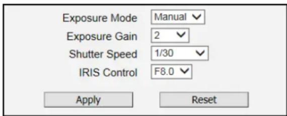
text_image
Exposure Mode Manual Exposure Gain 2 Shutter Speed 1/30 IRIS Control F8.0 Apply ResetIn manual exposure mode, the user can directly manually adjust the signal Exposure Gain, Shutter Speed, and even on select models, the IRIS Control (I-series zoom cameras only).
NOTE: WDR is disabled in manual exposure mode (see Image on page 72).
After changing any of the items above, press Apply to save the changes. The Reset button undoes the changes that had just been made but not Applied yet.
OSD

The section OSD (or OSD / Privacy Mask as shown in some cameras) allows users to add text to the upper or lower left corner of the video. This function is called Text Overlay or On-Screen Display (OSD). It is possible to display the camera name, date and time, IP address or any custom text as Text Overlay. The text is kept as small as possible and is not resizable. The text can be read normally when the video is enlarged on the display to 1:1 ratio. The purpose of having the text so small is to provide sufficient legal evidence while blocking the smallest possible area of the video to avoid valuable video evidence being blocked by text overlay. The text will be embedded into video and cannot be removed later upon playback or export.
It is possible to define up to 4 regions of text. If more than 1 region of text is enabled and positioned in the same location, then the texts will appear one below another, row by row.
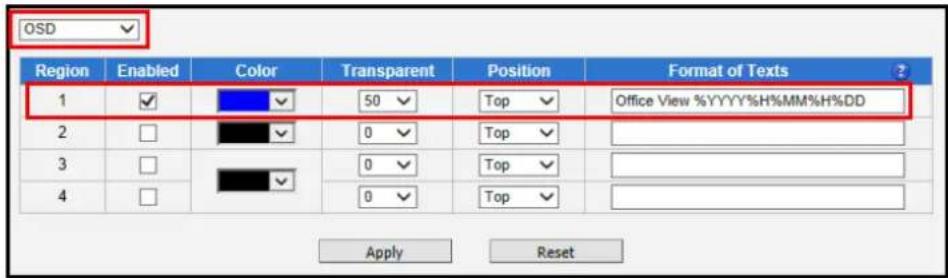
text_image
OSD Region Enabled Color Transparent Position Format of Texts 1 ✓ 50 ✓ Top ✓ Office View %YYYY%H%MM%H%DD 2 □ 0 ✓ Top ✓ 3 □ 0 ✓ Top ✓ 4 □ 0 ✓ Top ✓ Apply ResetIn the example above, one region of text was enabled with blue color and 50% transparency, located at left lower corner and containing the text of "Office View" together with current date. The date would be automatically changing every day, according to camera's date and time settings. The result of the example configuration would look like this (Live View page, 1:1 scale):
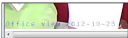
text_image
Office View 2012-10-23Below is the list of characters with special meaning that can be used in the text field:
| Parameters | Description |
| %YYYY | Year in four-digit format. For example, 2008 |
| %YY | Year in two-digit format. For example, 08 |
| %MM | Month in two-digit format. For example, 01 for January, 12 for December |
| %DD | Date in two-digit format. 01~31 |
| %hh | Hour in two-digit format. 00~23. Note that only 24-hour indication is supported. |
| %mm | Minutes in two-digit format. 00~59 |
| %ss | Seconds in two-digit format. 00~59 |
| %H | a hyphen, "-" |
| %C | a colon, ":" |
| %X | a slash, "/" |
| %N | show Camera Name (It might be truncated if exceeds max OSD length) |
After changing any of the items above, press Apply to save the changes. The Reset button undoes the changes that had just been made but not Applied yet.
Privacy Mask
Privacy Mask
Privacy Mask allows (or OSD/pusers to cover up some sensitive areas of the
video that should not be captured by the camera, such as manager's computer screen or bathroom ntrance. It is possible to configure several independent regions for masking. Microsoft Internet Explorer browser is required to configure the Privacy Mask. The privacy masks will be embedded into video and cannot be removed later upon playback or export.
NOTE: Privacy Mask is not available on hemispheric cameras in ePTZ mode.
On some cameras, OSD and Privacy Mask appear together on the same page tab as "OSD/Privacy Mask".
Privacy Mask of Fixed, Varifocal and Zoom Cameras
NOTE: This section describes the privacy mask setup for fixed and varifocal cameras, as well as zoom cameras under the E-series and models B210 and B410. For other zoom camera models, please refer to Privacy Mask of B-Series Zoom and PTZ Cameras on page 81.
It is possible to set up up to 4 regions of privacy masks. The adjustment of the privacy mask region can be done when region is checked under "Setup" column.
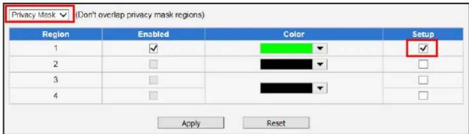
text_image
Privacy Mask ✓ (Don't overlap privacy mask regions) Region Enabled Color Setup 1 ✓ ✓ 2 3 4 Apply Reset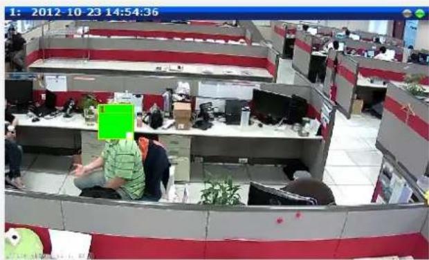
text_image
1: 2012-10-23 14:54:36You may resize and drag the region the same way as the motion detection regions: upper bar that contains the number of the region can be used for dragging the region across the video while the white box at the right lower corner of the privacy mask region can be used for resizing the region.
There are 4 pre-defined color options for privacy masks. If the user wants to use any other colors, please use URL commands to set up the privacy mask instead. To do that, please refer to the Guide that explains the use of URL commands.
When switching back to live view, the privacy mask would look like this:
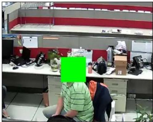
natural_image
Interior view of an office with two people seated at workstations, shelves stacked with items and a green overlay (no visible text or symbols)Please note that the Text Overlay (OSD) and Privacy Masks will take effect for both Stream 1 and Stream 2.
After changing any of the items above, press Apply to save the changes. The Reset button undoes the changes that had just been made but not Applied yet.
NOTE:
- It may take several seconds to update the region location on video display after pressing Apply!
- The privacy mask set on zoom cameras is retained on its original position. The image which is masked may move out of the masked area when the camera is zoomed in or out.
Privacy Mask of B-Series Zoom and PTZ Cameras
The Privacy Mask of B-Series zoom and PTZ cameras (except B210 and B410) is dependent on the configured preset points. These cameras can have up to 17 preset points, wherein up to four (4) privacy masks can be configured for each preset points.
Before setting the privacy mask, first, define the Home position and the preset points (as needed), see How to Set Preset Points on page 26.
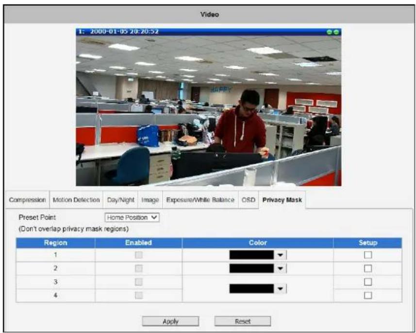
text_image
Video 1: 2000-01-05 20:20:52 Compression Motion Detection Day/Night XiImage Exposure/White Balance OSD Privacy Mask Preset Point Home Position (Don't overlap privacy mask regions) Region Enabled Color Setup 1 □ □ 2 □ □ 3 □ □ 4 □ □ Apply ResetTo create a privacy mask, do the following:
- Select the Preset Point where the mask should appear.
- Select a target Region number, then check Setup.
- A boxed region appears on the screen. Use the upper bar to drag the region you want to cover with the mask. The region may be resized by dragging the white box on the lower right corner.
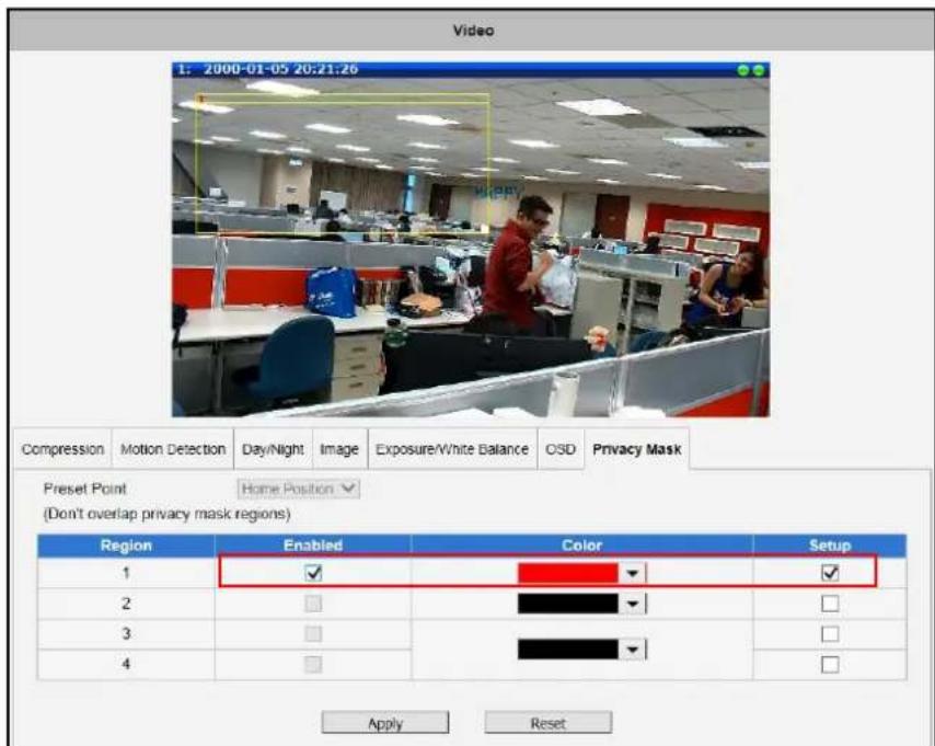
text_image
Video 1: 2000-01-05 20:21:26 Compression Motion Detection Day/Night XiImage Exposure/White Balance OSD Privacy Mask Preset Point Home Position (Don't overlap privacy mask regions) Region Enabled Color Setup 1 ✓ ✓ 2 3 4 Apply Reset-
Check Enabled and select the Color for the mask.
-
Click Apply to save and apply the changes.
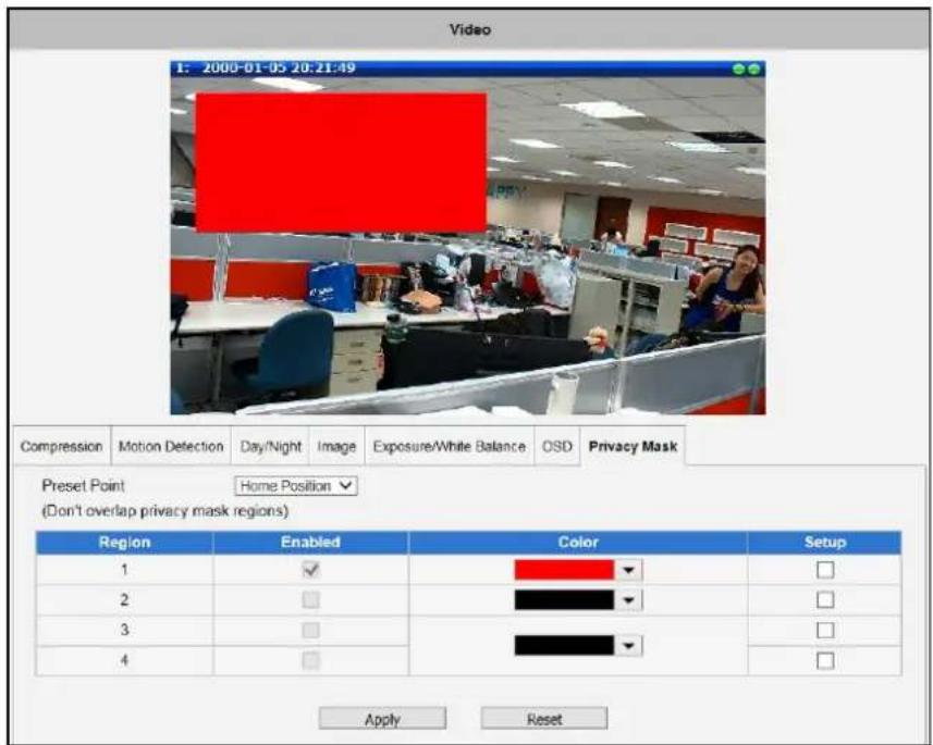
text_image
Video 1: 2000-01-05 20:21:49 Compression Motion Detection Day/Night XiImage Exposure/White Balance OSD Privacy Mask Preset Point Home Position (Don't overlap privacy mask regions) Region Enabled Color Setup 1 ✓ □ 2 □ □ 3 □ □ 4 □ □ Apply Reset- Repeat the above procedures to create more masks.
Note that the privacy mask created is only valid on the selected preset point. Once the camera is panned or zoomed in or out or moves to another preset point, the configured privacy mask will disappear. The mask will appear again once the live view goes back to that preset point.
Privacy Mask of I-Series PTZ and Speed Dome Cameras
For PTZ cameras under the 19x series, the privacy mask is dynamic. Thus, when the camera is panned to other directions, the region that is originally covered remains covered for privacy. Up to 32 privacy masks can be created on a PTZ camera with black color mask.
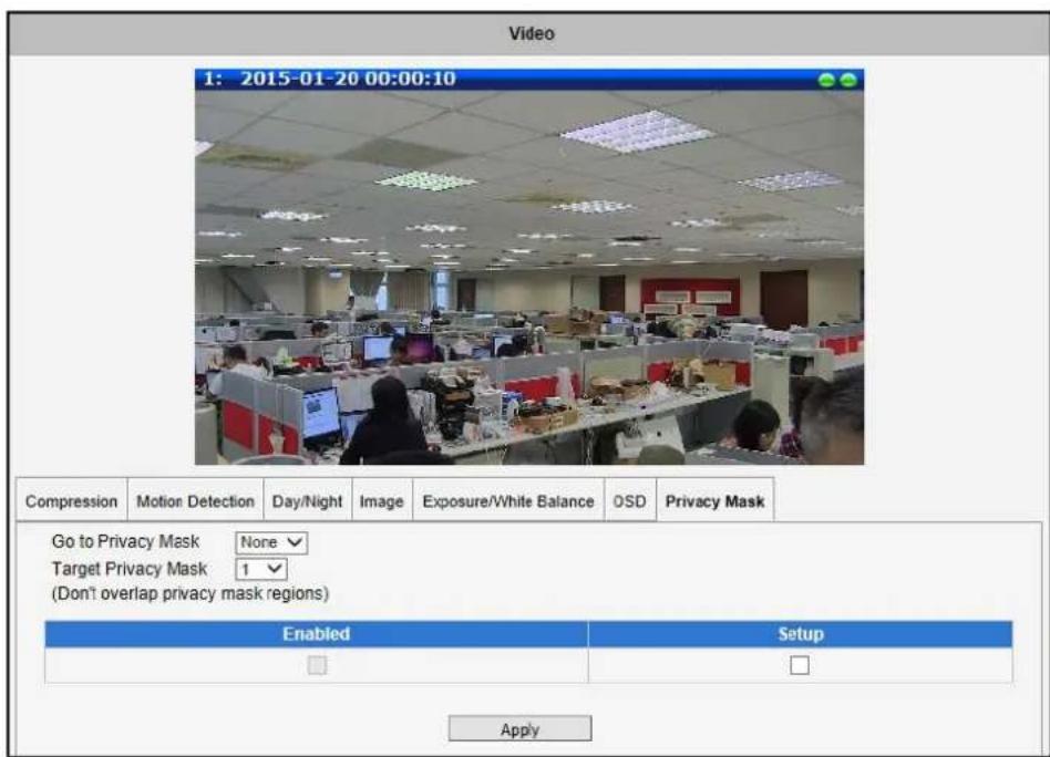
text_image
Video 1: 2015-01-20 00:00:10 Compression Motion Detection Day/Night Xi Image Exposure/White Balance OSD Privacy Mask Go to Privacy Mask None Target Privacy Mask 1 (Don't overlap privacy mask regions) Enabled Setup ApplyTo create a privacy mask, do the following:
- Pan the live view window towards the direction you want to mask.
- Select a Target Privacy Mask number, then check Setup.
- A boxed region appears on the screen. Use the bar to drag the region you want to cover with the mask. The region may be resized by dragging the white box on the lower right corner.
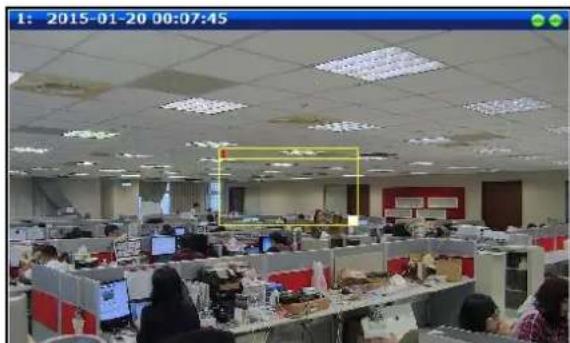
text_image
1: 2015-01-20 00:07:45- Check Enabled and press Apply to save the changes. The region is now covered with a black mask.
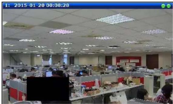
text_image
1: 2015-01-20 00:08:28- Repeat the above procedures to create more masks.
When the live view is panned to other direction and you wish to view the region with a privacy mask, select the region on Go to Privacy Mask and then click Goto.
On-Screen Graphics
On-Screen Graphics (OSG) is a new feature that allows placing custom image files on the top of the video as a layer. For example, it can be used as a watermark for security purposes, or a brand logo in the corner of the video image.
There is no interface within Web Configurator to configure On-Screen Graphics since it is a rarely used feature. The URL commands can be used to complete the task instead.
The image that can be used as OSG has to be in YUV format (Image raster graphics) before uploading to the camera. There are several freeware converters available that convert images to YUV format.
For example, one free trial version of YUV converter can be downloaded from Sunrayimage.com: http://www.sunrayimage.com/download/YUVTools_3.0_trial.zip
We do not guarantee the performance, terms of usage or availability of this product. The user has to read the terms of use first and proceed with installation if the terms are acceptable.
Please note that the image should not be larger than 640x480 pixels and should contain an even number of pixels. The image, once uploaded, cannot be resized. Therefore, please make sure that you have the image with the right size before uploading to the camera.
For example, we have the BMP logo with the size 204x106 that has been converted into YUV:
LOGO
When the image is ready, upload it to the camera by the following URL command:
http://192.168.0.100/cgi-bin/cmd/encoder?OSG\_IMAGE
Upon successful entry of user name ans password, the following upload window will appear.
Browse for the yuv file in your computer that you had prepared and press Apply.

text_image
OSG_IMAGE : Apply Reset Browse...When done, use another URL command to configure its position:
http://192.168.0.100/cgi-bin/cmd/encoder?OSG\_CONFIG=1,0,0,240,106,EB8080,4
... where the 7 parameters behind OSG_CONFIG mean following:
| Parameter Position | Description |
| 1 | 1 means enabled, 0 means disabled |
| 2 | X position |
| 3 | Y position |
| 4 | Width of the image |
| 5 | Height of the image |
| 6 | YYUUVV value of the background color of the image that is to be blended |
| 7 | Transparency level: 0 means 0%, 1 means 25%, 2 means 50%, 3 means 75%, 4 means 100% |
The result would look like this:
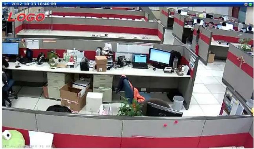
text_image
LOGOAudio

The section Audio is available only for audio-supported models. The
user interface for audio control looks as below:
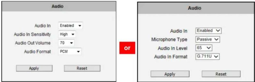
text_image
Audio Audio In Enabled Audio In Sensitivity High Audio Out Volume 70 Audio Format PCM Apply Reset or Audio Audio In Enabled Microphone Type Passive Audio In Level 65 Audio In Format G.711U Apply Reset| Parameters | Description |
| Audio In | The option “Enabled” would activate incoming audio (either line in or built-in microphone). The option “Disabled” would turn off the incoming audio. In such case, the video stream is captured without audio. |
| Audio In Sensitivity | Choose “High” when the target is farther away from the camera and choose “Low” when the target is near the camera. Under “High” mode, there may be more audio noise due to higher level of signal amplification.NOTE: Not available in all models. |
| Microphone Type | Select the type of microphone connected.NOTE: Available in vehicle-supported models only. |
| Audio In Level | For vehicle-support models, use this function to adjust the sensitivity level of audio input.NOTE: Available in vehicle-supported models only. |
| Audio Out Volume | The audio out volume level can be adjusted in the scale of 0-100. It will influence the volume level of the speakers connected to the camera.NOTE: Available only in camera models with audio out support. |
| Audio Format | Choose the compression format of audio: PCM, G.711A (A-law) or G.711U (μ-law). |
To adjust the volume level of the speakers connected to the PC that runs the Web Configurator in order to hear the audio from the camera's microphone or line-in device, go to Live View page and use the audio controls there:
Audio Muted:
Audio level adjusted to the maximum:
This volume control appears in user interface only when the Audio-in function of the camera has been "Enabled".
Event
This section describes how to setup the Event Handler, which deals with how the IP devices respond to situations. Each IP device can have a maximum of 10 Event Rules. Each rule includes one single trigger, and one or many responses. Several types of responses are available. And there are multiple external servers for the device to interact with.
When setting up Event Handler, there are four types of settings. Event Server, Event Configuration, Event Rules and Manual Event
Click the item before Event to expand the list.
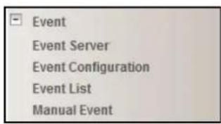
text_image
Event Event Server Event Configuration Event List Manual EventEvent Server
Event servers define whom the device may interact with. They can be other servers or devices on the network, or even the camera itself. Event Configuration sets up a list of what to tell the other party during interaction. Event list lays down the rules and conditions about when to initiate which responses from which triggers. The options available for Event rules are selected from the event servers and event configurations.
Event servers are classified as FTP servers, SMTP servers and HTTP servers
| Type | Network Address | Ports | User Name |
| FTP Server Configuration | none | 21 | none |
| SMTP Server Configuration | none | none | none |
| HTTP Server 1 Configuration | none | 80 | none |
| HTTP Server 2 Configuration | none | 80 | none |
FTP Server
FTP servers can receive snapshot or video uploads that are issued as part of the response from event handlers. You may setup one FTP server.

text_image
FTP Server Configuration Network Address Network Port 21 User Name User Password Mode Passive Max. Connection Time 10 sec. (0~60 sec) Apply ResetTo setup FTP servers, make sure to enter the network address of FTP server, the Network (FTP) port, the User Name and Password of FTP account, Connection mode (Passive or Active) and Connection time before timeout.
After changing any of the items above, press Apply to save the changes. The Reset button undoes the changes that had just been made but not Applied yet.
SMTP Server
SMTP servers can send email upon request from the IP device. The email can be a simple subject and text email, or attached with snapshot / video. You may setup two SMTP servers. The device will first attempt to send the message via the Primary email SMTP server. If the first attempt fails (after the Max connecting time), then the device will attempt to send via the secondary SMTP server. If the device sends email successfully via the primary SMTP server, then it will not use the secondary SMTP server.
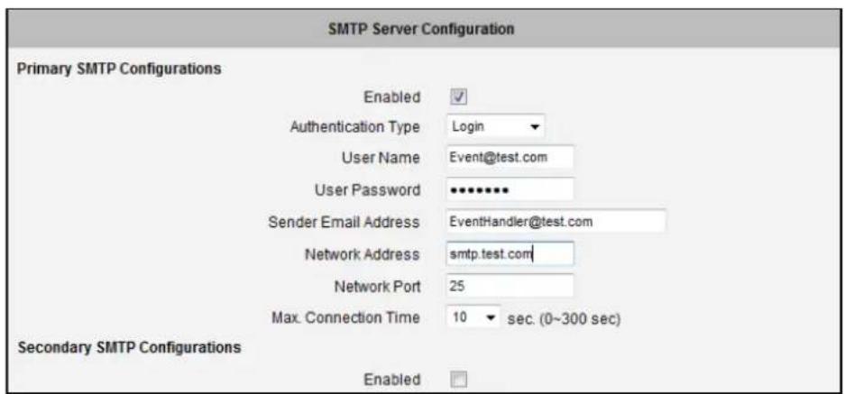
text_image
SMTP Server Configuration Primary SMTP Configurations Enabled ✓ Authentication Type Login User Name Event@test.com User Password •••••••• Sender Email Address EventHandler@test.com Network Address smtp.test.com Network Port 25 Max. Connection Time 10 sec. (0~300 sec) Secondary SMTP Configurations Enabled □To setup SMTP servers, make sure to enable the SMTP account and choose the proper Authentication type. There are many types available. The default is Login. We recommend you to use Auto Detection. Available authentication types include: Auto Detection, None, Login, Plain, Cram MD5, Digest MD5 and PoP Relay. Please also enter the User Name, Password, the email address displayed as sender (can be different than the user name), Network (SMTP server) address, Network (SMTP server) Port number and Max Connection time before timeout (in seconds).
After changing any of the items above, press Apply to save the changes. The Reset button undoes the changes that had just been made but not Applied yet.
HTTP Server
HTTP CGI servers are programs that run on web sites or many devices. They can be custom programmed to perform a large variety of actions based upon the input. You can define which CGI server to connect to here, and the user / password required to log into the target server. The actual message / command is setup in the Notification messages / URL commands section. You may define two separate CGI servers.
IP devices are also CGI servers. This means that IP devices can now issue commands to each other, which creates endless possibilities for highly coordinated response. The IP device can also give a loopback command to itself, in effect changing almost all possible settings dynamically. For detail on the commands used to control the cameras, please contact your customer representative.
An example will help you gain a better sense of how to utilize this unique function. Camera A is a fixed camera that looks at a corridor leading to the main hall. It has a motion detection window located near the point where the corridor arrives at the large hall. Camera B is a PTZ camera located in the hall, which is usually left on auto-tour patrol. When motion activity in the motion detection region triggers MD1 in Camera A, this then in turn activates an event rule in Camera A that gives out a command to Camera B. Camera B would then swivel to the preset point where the corridor leads into the entrance and switch to higher bit rate to temporarily provide clearer image. After the event ends, Camera B will go back to its normal routine in lower bit rate.
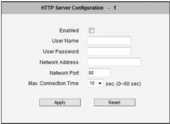
text_image
HTTP Server Configuration - 1 Enabled User Name User Password Network Address Network Port 80 Max. Connection Time 10 sec. (0~60 sec) Apply ResetTo setup HTTP servers, make sure to enable the HTTP server, enter the user name, the user password, Network (HTTP Server) address, Network (HTTP Server) port number and Max connection time before timeout (in seconds).
After changing any of the items above, press Apply to save the changes. The Reset button undoes the changes that had just been made but not Applied yet.
Event Configuration
Event configurations are the responses to be performed when an event is triggered. For most types of responses, you can create several different preset responses, then mix and match in event rules.
The configurable responses are classified as Digital I/O ports, Notification messages, Upload Video/Snapshot and Audio and Send URL Commands.
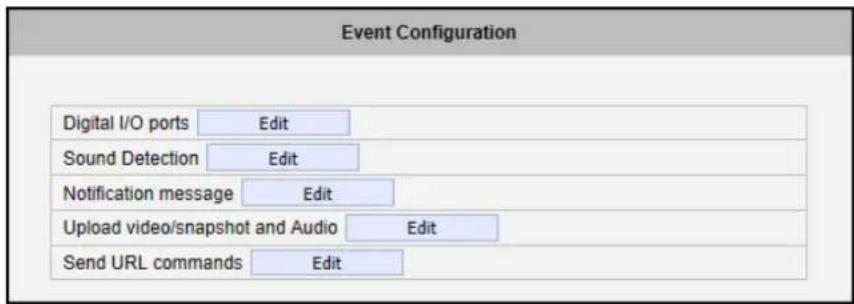
text_image
Event Configuration Digital I/O ports Edit Sound Detection Edit Notification message Edit Upload video/snapshot and Audio Edit Send URL commands EditNOTE: Digital I/O ports appear only for the camera models that support this function.
Digital I/O ports
Digital input/output ports (select models only) are used to connect digital input (DI) and digital output (DO) devices. DI is a trigger device like a switch or sensor (e.g. “panic button”), which when pressed or triggered, notifies the camera to perform specific actions or the DO device to respond. DO’s can be alarms or lights, etc.
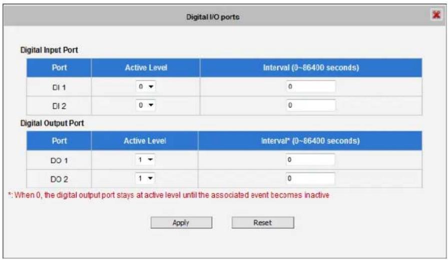
text_image
Digital I/O ports Digital Input Port Port Active Level Interval (0~86400 seconds) DI 1 0 0 DI 2 0 0 Digital Output Port Port Active Level Interval* (0~86400 seconds) DO 1 1 0 DO 2 1 0 *: When 0, the digital output port stays at active level until the associated event becomes inactive Apply ResetThe Digital I/O Ports page displays the number of available DI and DO ports on the camera, which varies depending on camera model.
DI: To configure the digital input device, define the active level and trigger interval of the DI. The default Active Level is “0”, which means the DI device remains inactive unless triggered. A good example is a “panic button”, which always stays in inactive mode “0” until the button is pressed; when the button is pressed, its active level becomes “1” which means the DI is triggered. Active level “1” returns back to “0” (inactive mode) after the specified Interval. The Interval is the duration of time when the trigger remains in active mode which is also the minimum time interval between the previous trigger and the next. For example, if the interval is set to “5 seconds”, the DI will not respond if the “panic button” is pressed within 3 seconds after the previous trigger. To issue another trigger, press the button after 5 seconds from the previous trigger.
DO: To configure the digital output device, define the active level and response interval. The default Active Level is “1”, which means the DO will turn to active mode and respond once triggered. The duration of its response will last according to the set Interval. A good example is an alarm siren, wherein the siren will start sounding only when it is triggered by an event or another device like a DI. The siren will stop sounding once the set interval time elapsed.
After changing any of the items above, press Apply to save the changes. The Reset button undoes the changes that had just been made but not yet applied or saved.
Sound Detection
Sound detection is available on cameras with Audio in capability and is shown on the user interface only if the Audio In function is enabled in Audio setup menu (see Audio on page 88). Sound detection is used to trigger the camera or another camera to perform specific actions or a digital output device, such as alarms or lights, etc. to respond.
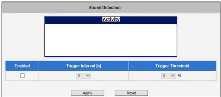
text_image
Sound Detection Activity Enabled Trigger Interval [s] Trigger Threshold □ 0 0 % Apply ResetCheck the Enabled box to enable Sound Detection.
The Trigger Interval refers to the time interval of the first detected sound to the next detected sound. For example, if trigger interval is set at 5 (seconds), the next sound detection is triggered only after 5 seconds. If the next sound is detected 3 seconds after the first sound, the trigger is not activated.
To set the range or loudness of sound, set the Trigger Threshold. This helps define which sound is considered loud enough to be a trigger. For example, the sound of blowing wind should not be considered, while the sound of a door creaking is a cause for alarm. The red line on the Activity graph shows the threshold set at 15% . The blue graph shows the sound activity. If the blue graph exceeds the red line, sound is triggered.
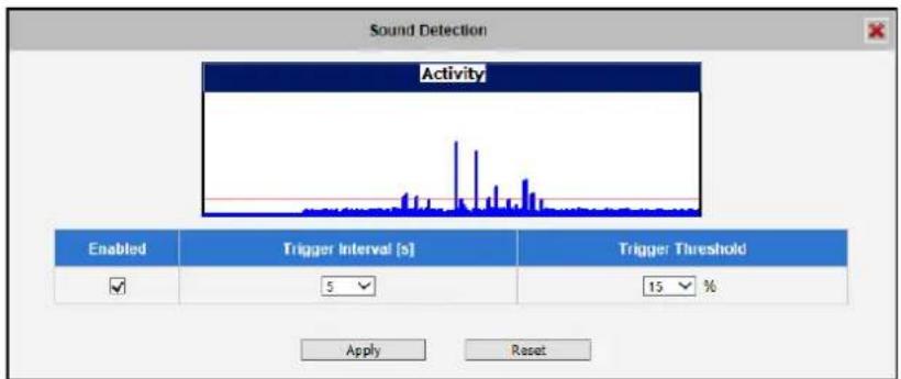
text_image
Sound Detection Activity Enabled Trigger Interval [s] Trigger Threshold ✓ 5 15 % Apply ResetHow to choose the most optimal trigger threshold level? The rule of thumb, keep the trigger threshold as small as possible while not causing false alarms.
After changing any of the items above, press Apply to save the changes.
Notification message
*Pre-requisites: SMTP server / HTTP CGI server setup.
Notification messages may be sent to either an email or a HTTP CGI server. If sent to a CGI server, it works the same as an URL command, but it does not allow a second message at end of event. You may configure up to three preset massages. You can configure a message, but disable it. This will allow you to keep the settings without using it, which will be useful in testing and troubleshooting.
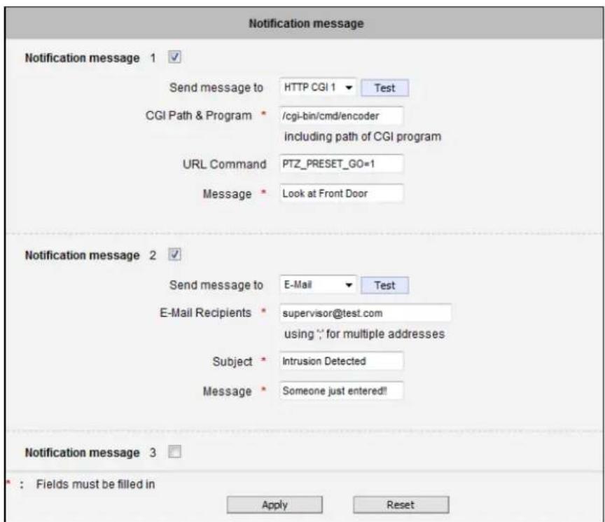
text_image
Notification message Notification message 1 ✓ Send message to HTTP CGI 1 ▼ Test CGI Path & Program * /cgi-bin/cmd/encoder including path of CGI program URL Command PTZ_PRESET_GO=1 Message * Look at Front Door Notification message 2 ✓ Send message to E-Mail ▼ Test E-Mail Recipients * supervisor@test.com using "; for multiple addresses Subject * Intrusion Detected Message * Someone just entered!! Notification message 3 □ : Fields must be filled in Apply ResetTo setup Notification Messages, make sure to enable the message and then determine what type of message to send (HTTP CGI or email).
If you are sending to CGI server, you need to enter the CGI path, the URL command itself, and an optional message.
If you are sending email, please enter the recipient E-Mail address, the email subject, and the body message.
After changing any of the items above, press Apply to save the changes. The Reset button undoes the changes that had just been made but not Applied yet.
Upload Video/snapshot and Audio
*Pre-requisites: SMTP server / FTP server / HTTP CGI server setup.
IP devices may send video recording / snapshots to your chosen server upon event. Video will be in .RAW format, while snapshots will be .JPG files. You can define up to three groups of settings to upload video/snapshot. Snapshots can be sent to E-mail, FTP and HTTP CGI servers, while videos can be uploaded to FTP, HTTP CGI servers, and local storage (for select models). If Audio in is enabled in device, the uploaded video will include audio.
The parameters needed to setup this function are different for each task combination (snapshot / ftp or video / HTTP... etc), and are explained below:
| Enable | UI | ||||||
| Upload video/snapshot and Audio 1 √ | |||||||
| Upload Media Type | Snapshot | Video | Upload Media Type ● Snapshot ○ Video | ||||
| Upload Media to | FTP | CGI | FTP | CGI | Local | Upload Media To E-Mail ▼ | |
| Upload Period | Y | Y | Y | Y | Y | Y | Upload Period 0 (0~86400 seconds) |
| Image during Upload Period | Y | Y | Y | Images during Upload Period 0(Use 0 for maximum number of images) | |||
| Pre-Buer Time | Y | Y | Y | Pre-Buffer Time 0 ▼ (0~10 Second ) | |||
| Image File Name | Y | Y | Y | Y | Y | Image File Name Front_Door_%YYYY_%MM_%DD | |
| Upload Path | Y | Y | Y | Upload Path Camera/%N | |||
| CGI Path & Program | Y | Y | CGI Path & Program | ||||
| E-Mail Recipients | Y | E-Mail Recipients using ; for multiple addressed | |||||
| Subject | Y | Subject Front Door Snapshot | |||||
| Video Source | Y | Y | Y | Y | Y | Y | Video Source 1 ▼ |
Upload Video/snapshot and Audio checkbox: this decides if this rule is in effect, or disabled.
Sometimes it is useful to keep the settings for troubleshooting purposes, but keep them as disabled.
Upload Media to: these define the task at hand, and change the field that needs to be filled out.
Upload Period: IP device will provide video/snapshots for the number of seconds here. It will stop uploading video/snapshot at the end of this period. If you have video management software recording from this camera at the same time, the normal recording through NVR will not be affected, and goes on throughout the event period and afterwards. But the special upload session will end as the event ends.
Image during Upload Period: This is used only by snapshots. This tells the camera how many snapshots it should attempt to capture during the Upload Time. If this value is set to 0, then the IP device will attempt to capture as many snapshots as possible. Depending upon the device loading, the number of snapshots taken may not reach the number you specified.
Pre-Buffer Time: This is only used by video. If this is set to more than 0, then the IP device will start to buffer video in its internal memory. The maximum pre buffer is 10 seconds. When an event requires video upload, the IP device will first upload the video taken right before the event then keep uploading until it reaches the upload time.
Image File Name/ Upload Path: You will need to specify rule for file names and upload paths (upload path is not needed for Email. Just put a slash "/" in the field). The rules contain flexible parameters. A sample rule and corresponding filename will look like this:
Front_Door_%YYYY_%MM_%DD@%hh%mm%ss
Front_Door_2009_10_12@195037.JPG
Upload Path folders may also be named dynamically. For the IP device to create folders on FTP and HTTP CGI servers properly, your FTP/CGI account will need to have permission to create folders. For syntax on auto naming, please see online help or the inset box at the end of this section.
The symbol “%” cannot be the first character in filename or upload path. Please use either an alphabet or a number as the starting character. For Upload Path, be sure to start and end either a backslash“. An example will be : \Backgate%MM%DD\
CGI path & Program: Some CGI servers may require special info and settings. Please refer to CGI server designer for this section. IP devices do not allow upload of Snapshots / Video into their embedded CGI servers.
E-Mail Recipient / Subject: When uploading video/ snapshots via email, these fields are required.
Video Source: Choosing the video source from video 1 or video 2.
Auto Naming Rules for Files and Folders:
To properly track images and videos, a well thought out naming rule is necessary. There are a number of automac variables available to design a proper naming system, which may be used both on les and folders.
| Symbol | Descripon | Example |
| %YYYY | 4 digits for year | 2009 for year 2009 |
| %YY | the last 2 digits of 4 digits year | 09 for year 2009 |
| %MM | two digits for month. 01~12 | 01 for January |
| %DD | two digits for date. 01~31 | 01 for the 1st day of a month |
| %hh | two digits for hour. 00~23 | |
| %mm | two digits for minute. 00~59 | |
| %ss | two digits for second. 00~59 | |
| %W | a space character. '' | '' |
| %N | camera name | camera-1 |
| %Y | File serial counter. It starts from 1 in every uploading task. The counter will be increased by 1 for next uploading le. | 1,2,3,4,5,... |
Example
- Entrance-%YYYY-%MM-%DD@%hh%mm%ss for me 2009/06/05 22:50:30.
The full name is Entrance-2009-06-05@225030
- X_%w-%N_TEST%Y for camera name is 'my-camera' and three successive uploaded les.
The full names of these three les are
X_-my-camera_TEST1, X_-my-camera_TEST2, X_-my-camera_TEST3
Send URL commands
*Pre-requisites: HTTP CGI server setup.
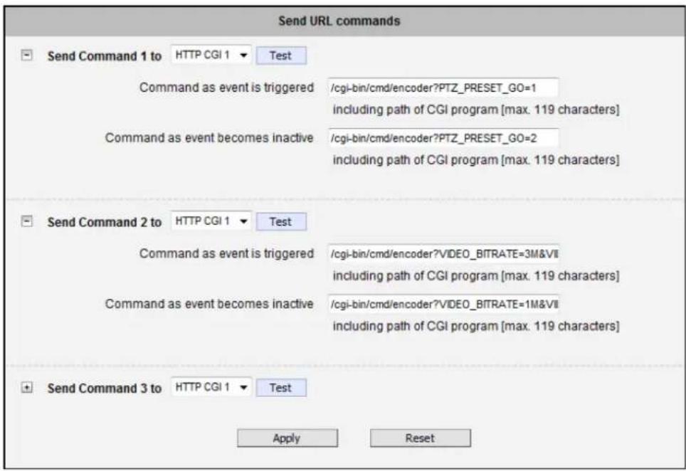
text_image
Send URL commands Send Command 1 to HTTP CGI 1 Test Command as event is triggered /cgi-bin/cmd/encoder?PTZ_PRESET_GO=1 including path of CGI program [max. 119 characters] Command as event becomes inactive /cgi-bin/cmd/encoder?PTZ_PRESET_GO=2 including path of CGI program [max. 119 characters] Send Command 2 to HTTP CGI 1 Test Command as event is triggered /cgi-bin/cmd/encoder?VIDEO_BITRATE=3M&VII including path of CGI program [max. 119 characters] Command as event becomes inactive /cgi-bin/cmd/encoder?VIDEO_BITRATE=1M&VII including path of CGI program [max. 119 characters] Send Command 3 to HTTP CGI 1 Test Apply ResetURL commands can be sent to HTTP CGI servers upon event. This provides the possibility of highly intelligent response upon event. IP devices and many other devices also have embedded CGI servers that may be controlled.
When Event Handler sends an URL command, it will send one set of command when the event is triggered, and another as the event becomes inactive. Depending on the CGI design, the URL commands may be able to be stringed together, and multiple commands may be issued in a single line.
An example would be when the access control device at the entrance detects an entry, this device provides a DI signal to the PTZ camera, and triggers an event. This event then sends a loopback command to the PTZ Camera itself (by setting its own IP as the HTTP CGI server). The PTZ Camera then moves to a preset location, stays until the event is over, and then moves back to another location. At the same time it moves to the pre-set location, it increases the bitrate from 1M to 3M, and the frame rate from 4 fps to 8 fps. The bitrate / fps changes are reverted at the end of event.
Event List
You may define a maximum of 10 Event rules, which will be shown in abbreviated form in the Event List panel. It will display under each Event ID, the days of the week it will be active, the start time and duration of the active period, the type of the source of trigger, and the actions used in the response. If the row is grayed out, this means the rule is currently not enabled and stays inactive.
| Event List | |||||
| ID | Week Day | Start | Duration | Source | Action |
| 1 | 1234567 | 00:00 | 24:00 | MD1 | CMD1 |
| 2 | 1234567 | 00:00 | 24:00 | NONE | NONE |
| 3 | 1234567 | 00:00 | 24:00 | NONE | NONE |
| 4 | 1234567 | 00:00 | 24:00 | NONE | NONE |
| 5 | 1234567 | 00:00 | 24:00 | NONE | NONE |
| 6 | 1234567 | 00:00 | 24:00 | NONE | NONE |
| 7 | 1234567 | 00:00 | 24:00 | NONE | NONE |
| 8 | 1234567 | 00:00 | 24:00 | NONE | NONE |
| 9 | 1234567 | 00:00 | 24:00 | NONE | NONE |
| 10 | 1234567 | 00:00 | 24:00 | NONE | NONE |
You may start creating a new event by clicking the event ID number in the list, for example "2". There are several parts to the Event rule:
When is it active?
You may choose to enable the rule or not. The settings will be kept in internal memory even if the event rule is disabled. Select the days in a weekly cycle in which this rule and schedule is active.
Determine the start time and duration of the active period. For example, a rule that lets motion detection trigger snapshot uploads to FTP would only take place after 19:00 each day for 12 hours. Outside of this time the rule will not be active.
In the example below, the event handler rule is active 24 hours a day, 7 days a week.
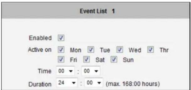
text_image
Event List 1 Enabled ✓ Active on ✓ Mon ✓ Tue ✓ Wed ✓ Thr ✓ Fri ✓ Sat ✓ Sun Time 00 ▼ : 00 ▼ Duration 24 ▼ : 00 ▼ (max. 168:00 hours)How is it triggered?
Events may be triggered by one of the several sources.
Scheduler: You can trigger an event based on the set schedule. For example, in the example below, the schedule is set for an alarm to sound at 4:00, and will sound once every 5 minutes within the next 10 minutes.
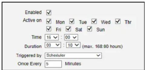
text_image
Enabled ✓ Active on ✓ Mon ✓ Tue ✓ Wed ✓ Thr ✓ Fri ✓ Sat ✓ Sun Time 16 ✓ : 00 ✓ Duration 00 ✓ : 10 ✓ (max. 168:00 hours) Triggered by Scheduler ✓ Once Every 5 MinutesDls: For selected models only, the IP device may be triggered by Digital Input. Select the digital input and make sure to configure it on the Event Configuration page
Motion: You may trigger the event if one or many Motion Detection regions encounter a motion trigger. Trigger from any of them will initiate the event. The duration of event will be the same as the MD trigger length, or the Trigger interval time, defined in the Motion Detection section on Video Adjust page. In the example below, Motion Detection region 1 is used as the event trigger.
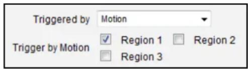
text_image
Triggered by Motion Trigger by Motion ✓ Region 1 □ Region 2 □ Region 3You may also ask the event to be repeatedly triggered during this scheduled time. The interval is determined in minutes. You may use this with email / FTP upload to take snapshots at regular intervals.
Sound Detection: The event may be triggered when sound is detected. This feature is available on cameras with Audio in capabilities only. The Sound Detection must be configured first to use this feature.
Switch to Night mode: This is available to selected models only. When camera changes between day and night modes, the embedded event handler will notice this change, and may act upon this information.
Potential uses include changing the motion detection profile to another set of Event MD parameters. By having two sets of parameters each optimized for day and night, this provide better overall accuracy in both day and night conditions. Some night time only MD regions may also be activated this way. The event period will end when the camera returns to day mode, which will then reset the camera to the original settings.
Device boots successfully: This will trigger the event responses once the device boots up. You can use this to create a notification system that keeps record of when the device has been rebooted via email.
Reboot device: This triggers the event response when the device is shut down via web UI "Save and Reboot". Use this to keep record of when was the device setting edited. Note that this will not take effect when the device is unplugged, as this is not normal shutdown.
Fail to write storage (with storage card only): Trigger occurs when there is an error in writing data to the memory card.
Remove storage media (with storage card only): Trigger occurs when the memory card is suddenly removed from the device.
What responses will occur?
Available responses vary depending on what triggered the event.
Response To

Send notification message

Upload video/snapshots

Change Motion Detection Profile

Send URL command
Digital Output (selected models only): This is a useful link to other devices. Click to include this in the response for this rule.
Send notification Message: Select from the three pre-defined messages which you've setup in the Event Configuration section. You may enable multiple messages at the same time. For sending Email, please limit the recipient to one per event rule. If you need to send email to more than one recipient, please use separate event rules triggered by the same trigger.
Upload video/snapshots: Select which of the event configurations to include in this response set. If you are sending email via upload video and sending notification message at the same time, the system will automatically merge the two emails into one. The subject and image will be based upon the Upload snapshot Event configuration enabled, but the message in the body text will be based upon the Notification messages.
In general, please stick to the "one email per event rule" limit for best performance.
Change Motion Detection profile: This will switch the profile of the selected Motion Detection region from Runtime profile to Event profile. The profile will return to runtime settings at the end of this event. You may program one motion detection region to be disabled at runtime, but enable it with event handler under some circumstances.
Send URL command: Select the URL command to include in the response set. Two different commands will be sent at the time when the event is triggered and un-triggered. For example, going to a preset point, if the device is a PTZ camera, and there are preset points already configured in PTZ setup page, then you may include this in the response section of the event rule by using Send URL Command method. It is possible to let the camera return to another preset point at the end of the event.
Change to Day / Night Mode (Selected models only): For some models, you may force the Camera into Day or Night mode. The camera will return to its previous setting (whether auto or forced day/night) upon the end of the event.
After changing any of the items above, press Apply to save the changes. The Reset button undoes the changes that had just been made but not Applied yet.
Manual Event
You may select one event in the Manual Event area below the event list to be triggered via web user interface.
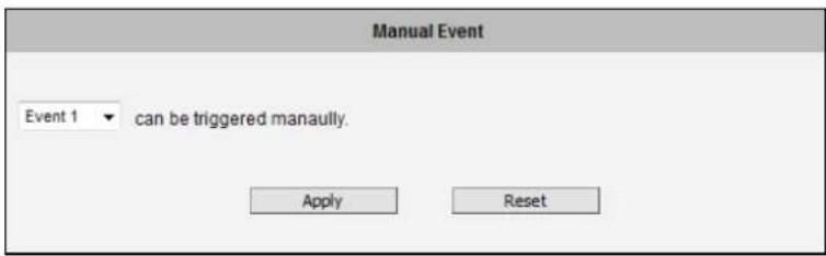
text_image
Manual Event Event 1 ▼ can be triggered manually. Apply ResetAfter changing any of the items above, press Apply to save the changes. The Reset button undoes the changes that had just been made but not Applied yet.
Once selected, the trigger button on the video display screen will show as clickable. Click to trigger the selected event. This is useful during event rule testing.
The live view panel would look like this:

text_image
Web Configurator TriggerLocal Storage Management
The cameras that come with built-in local storage capability will have the Local Storage menu shown on the Setup Page when a memory card is inserted into the memory card slot of the device.
Video recording configurations such as the length of recording, video stream, etc. must be setup on the Event Configuration menu (see Upload Video/snapshot and Audio on page 96). After setting the Upload Video configurations, create an event on the Event List menu (see Event List on page 100) to either record the video on a scheduled time or when triggered by an event. Note that only videos can be recorded on the memory card, snapshots cannot.
Make sure to "format" the memory card first when using the card for the first time or if the card has been used in other devices.
Click the + Local Storage menu on the Setup Page. Three (3) submenu items are available – Status, Utilities, and File Management. If the memory card has not been formatted or mounted, the File Management submenu is grayed out and cannot be accessed.
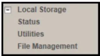
text_image
Local Storage Status Utilities File ManagementStatus
When the mass storage has not been formatted or mounted yet, the camera would not know the status of the storage, and the output would be as follows:
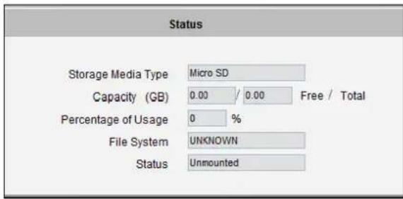
text_image
Status Storage Media Type Micro SD Capacity (GB) 0.00 / 0.00 Free / Total Percentage of Usage 0 % File System UNKNOWN Status UnmountedIf the mass storage has been formatted or mounted already, the Status page will show the details of the storage:
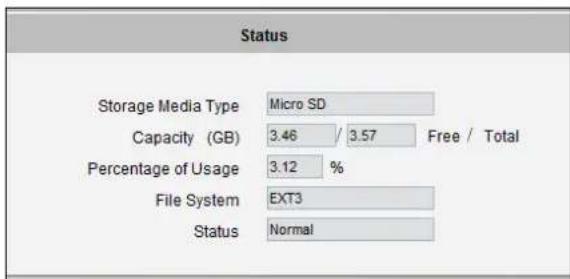
text_image
Status Storage Media Type Micro SD Capacity (GB) 3.46 / 3.57 Free / Total Percentage of Usage 3.12 % File System EXT3 Status NormalIn case of IP cameras with installed memory cards, the Storage Media Type will show "Micro SD".
NOTE: Supports microSDHC and microSDXC cards only.
The capacity of the disk is shown in Gigabytes.
The file system is Linux based EXT3, which is different from Windows based PC file systems. If you remove the storage from the camera and plug it directly to Windows based PC, it may not be able to read its content. The chapter File Management explains the correct ways of accessing files of the local storage.
Utilities
The "Utilities" are responsible for managing the storage itself rather than the files on the storage. There are three utilities – Mount, Format and Scan.
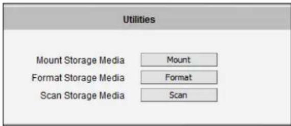
text_image
Utilities Mount Storage Media Mount Format Storage Media Format Scan Storage Media ScanMount
When the Mount storage media button shows "Mount" button then it means that the mass storage has been inserted to the camera, but the connection between camera and the storage has not been established yet. By pressing the "Mount" button, the storage becomes active. It is then possible to check the Status of the disk, write or read data on the disk, remotely access the storage by Web Configurator or FTP client, etc.
When pressing the "Mount" button, the mounting process will start.

text_image
Utilities Mount Storage Media Mount Format Storage Media Format: Scan Storage Media Scan Message from webpage Storage media was mounted successfully. OKUnmount
Once the drive has been mounted, it can later be unmounted by pressing the "Unmount" button, if necessary.
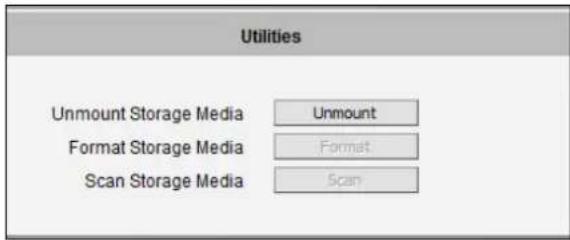
text_image
Utilities Unmount Storage Media Unmount Format Storage Media Format Scan Storage Media Scan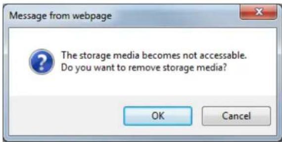
text_image
Message from webpage The storage media becomes not accessible. Do you want to remove storage media? OK Cancel
text_image
Utilities Unmount Storage Media Format Storage Media Scan Storage Media Message from webpage Storage media can be safely removed now. OKThat Unmount function is used when the camera is to be shut down for maintenance or when the mass storage has to be physically removed for some reason. The purpose of unmounting is to protect the currently processed data on mass storage at the moment of removal of the storage. If the local storage is being used by camera and some videos or snapshots are being recorded to the disk, then the sudden shutdown or removal of the disk without unmounting may corrupt the file that is currently being used by the camera. The rest of the files are not influenced in any way. Please note that “Save&Reboot” function of the camera also does unmounting automatically for the user.
Mount Failure
If the inserted disk's file system is not EXT3, then the Mounting would fail and an error message would appear.
The common reason is that the disk may have previously been used in other file systems, such as Windows based PC or photo camera. If the disk does not have the right file system, then you will get an error message. In that case the disk has to be formatted first. ACTi camera provides convenient formatting function within Web Configurator.
Format
When the disk is inserted to the camera for the first time, it is recommended to format it, to make sure the file system of the disk would be compatible with camera. If the disk has already been mounted, the "Format" button is grayed out, unmount the disk first to enable the "Format" button.
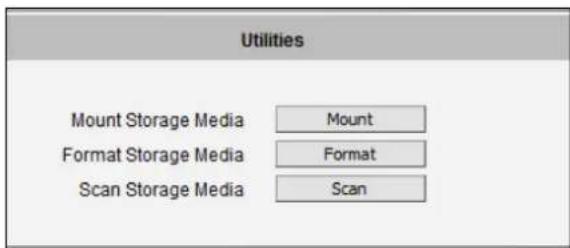
text_image
Utilities Mount Storage Media Mount Format Storage Media Format Scan Storage Media Scan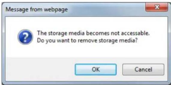
text_image
Message from webpage The storage media becomes not accessible. Do you want to remove storage media? OK Cancel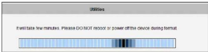
text_image
Utilities It will take few minutes. Please DO NOT reboot or power off the device during format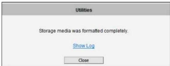
text_image
Utilities Storage media was formatted completely. Show Log Close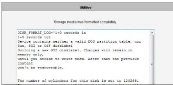
text_image
Storage media was formatted completely. DISK FORKAT LOG='1+0 records in 1+0 records' out Device contains neither a valid DOS partition table, nor Sun, SGI or OSF disklabel Building a new DOS disklabel. Changes will remain in memory only, until you decide to write them. After that the previous content won't be recoverable. The number of cylinders for this disk is set to 120286.Format Failure
If the disk is damaged or it is not within the specifications of the camera, the formatting may fail. When this happens, there is no way to continue using that disk, and it has to be replaced with a proper one.
Scan
To check the "health" of the disk, it is possible to use the "Scan" function. If the disk has already been mounted, the "Scan" button is grayed out, unmount the disk first to enable the "Scan" button.
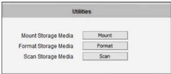
text_image
Utilities Mount Storage Media Mount Format Storage Media Format Scan Storage Media Scan
text_image
Utilities It will take few minutes. Please DO NOT reboot or power off the device during scan.
text_image
Utilities Storage media was scanned completely. Show Log Close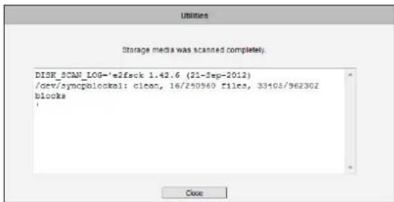
text_image
Utilities Storage media was scanned completely. DISK_SCAN_LOG='e2fsck 1.42.6 (21-3ep-2012) /dev/syncpblock1: clean, 16/250960 files, 33405/962302 blocks CloseScan Failure
The scanning would fail if the disk is not recognized by the camera. Make sure that the disk has been properly formatted and mounted to the camera.
File Management
The File Management submenu allows users to graphically see the amount of videos recorded on the memory card through its timeline, as well as the type of triggers that may have occurred during the recording.
NOTE: Make sure to "format" the memory card first when using the card for the first time or if the card has been used in other devices.
Click a video timeslot from the timeline bar to select and view its snapshot. A selected video timeslot is indicated by a blue bar.
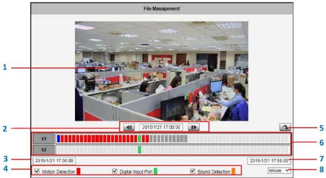
text_image
File Management 1 2 2015/1/21 17:00:00 S1 S2 3 2015/1/21 17:00:00 Motion Detection Digital Input Port Sound Detection 2015/1/21 17:59:00 Minute 5 6 7 8NOTE: The Snapshot window is available only when using Internet Explorer browsers.
| Item | Description | |
| 1 | Snapshot Window | Displays the snapshot of the selected video timeslot. |
| 2 | Time of Selected Video | Shows the time of the selected video timeslot. Click the arrow buttons to scroll the timeline bar to the previous or next page. |
| 3 | Start Time of Timeline Bar | The starting time (left side) of the timeline bar. |
| 4 | View Event | Check the box to view events recorded when the following is triggered:Motion Detection: When this box is checked, the timeline bar will show red bars if motion is detected on a timeslot.Digital Input Port: When this box is checked, the timeline bar will show green bars if the digital input is triggered on a timeslot.Sound Detection: When this +box is checked, the timeline bar will show orange bars if the sound detection is triggered on a timeslot. |
| 5 | Go to Current Time | Click the button to go the current time. |
| 6 | Timeline Bar:S1 (Video Stream 1)S2 (Video Stream 2) | Allows users to browse and select the recorded videos by timeslot. Video recorded from stream 1 is shown on S1 timeline bar, while video from stream 2 is shown on S2. The bars on the timeline bar indicate each video timeslot.Blue bar indicates the current selected video timeslot; the snapshot is shown on the window.Dark gray bar indicates a recording is present.Light gray bar indicates no recording.Red bar indicates motion is detected on that timeslot.Green bar indicates the digital input is triggered on that timeslot.Orange bar indicates the sound detection is triggered on that timeslot. |
| 7 | End Time of Time Bar | The ending time (right side) of the timeline bar. |
| 8 | Time Unit | Select the unit of time to use to display the timeline bar. The default time unit is by “Hour”. |
How to Export Video?
- Select the starting point of the video to export from timeline bar. The bar turns blue.
- Click the right mouse button and select Mark Export Start.
- Click the ending point of the video to export. The bar turns blue.
- Click the right mouse button and select Mark Export End. The scope of the starting to the ending timeslot is marked blue.
- Click the right mouse button and select Export Video.
- Save the video file (.raw).
The exported video can be played back using Archive Player, a free video player tool, downloadable from the website
(http://www2.acti.com/corpweb/Tools/ProductSelector/SupportToolsUtilities.aspx)
NOTE: The camera memory is allocated to deliver continuous live streaming to all connected users or devices, such as for NVR recording purposes. The camera will store as many P-frames as possible on the memory card. However, due to camera memory limitation, the camera may record only the I-frames on the memory card. To increase the number of P-frames to record on the memory card, it is recommended to lower the FPS, bit rate and resolution of Stream 1 (see Compression on page 63).
System
System
The section System provides the list of functions that help manage the
camera. The [+] mark before System indicates that the list can be expanded by clicking on it.
Once expanded, the list can later be collapsed again by clicking on the [-] mark.
User Account
User Account
The section User Accounts allows doing following user management
tasks:
- Change the account name or password of the Root account that has a full access to the camera.
- Create up to 10 common users that only have an access for live view and PTZ control.
- Enable/disable the option of seeing the live view without needing user name and password (anonymous login), which is especially convenient function for camera installers on the field. For security reasons, account name and password is always required when entering Setup page of Web Configurator or when trying to access camera or change settings by URL commands.
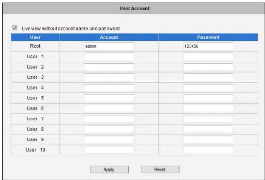
text_image
User Account ✓ Live view without account name and password User Account Password Root hemadmin 123456 User 1 User 2 User 3 User 4 User 5 User 6 User 7 User 8 User 9 User 10 Apply ResetAfter changing any of the items above, press Apply to save the changes. The Reset button undoes the changes that had just been made but not Applied yet.
System Info
System Info
The section System Info provides the full information about camera
status, settings and log. This information is very helpful while doing the camera configuration, maintenance or troubleshooting.
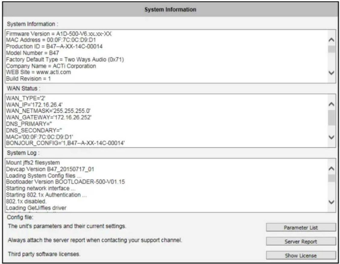
text_image
System Information System Information : Firmware Version = A1D-500-V6.xx.xx-XX MAC Address = 00:0F:7C:0C:D9:D1 Production ID = B47--A-XX-14C-00014 Model Number = B47 Factory Default Type = Two Ways Audio (0x71) Company Name = ACTi Corporation WEB Site = www.acti.com Build Revision = 1 WAN Status : WAN_TYPE='2' WAN_IP='172.16.26.4' WAN_NETMASK='255.255.255.0' WAN_GATEWAY='172.16.26.252' DNS_PRIMARY=" DNS_SECONDARY=" MAC='00:0F:7C:0C:D9:D1' BONJOUR_CONFIG='1,B47--A-XX-14C-00014' System Log : Mount jffs2 filesystem Devcap Version B47_20150717_01 Loading System Config files ... Bootloader Version BOOTLOADER-500-V01.15 Starting network interface ... Starting 802.1x Authentication ... 802.1x disabled. Loading GetJiffies driver Config file: The unit's parameters and their current settings. Parameter List Always attach the server report when contacting your support channel. Server Report Third party software licenses. Show LicenseThe Server Report is a convenient way of exporting the full list of camera related information in a text format, so that it can be sent to the technical support team for faster service.
Factory Default
Factory Default
The section Factory Default allows the camera settings be reset to the
original factory settings.
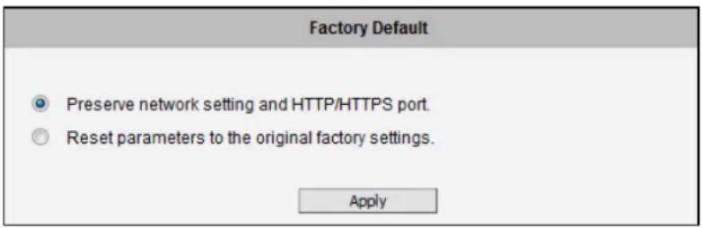
text_image
Factory Default Preserve network setting and HTTP/HTTPS port. Reset parameters to the original factory settings. ApplyIf you want to keep network settings and restore other settings to factory default, please select the first option. If you select the second one instead, all the settings would be removed during factory default. You will have to use factory default IP setting to connect to this camera.
Firmware Upload
Firmware Upload
The section Firmware Upload allows remote upgrade or downgrade of camera firmware. The upgrade to newer version is usually done in order to gain new functions or fix existing bugs or limitations while downgrade to older version is used mostly for integration purposes where the newly purchased camera model comes with the newer firmware version than supported by a third party video management system of a given project.
Firmware uploading can be done in two ways, choose to download and select the firmware image manually or use auto-upgrade function through "Firmware Upload from the Download Center" so that the camera will connect to internet and find the latest firmware image automatically.
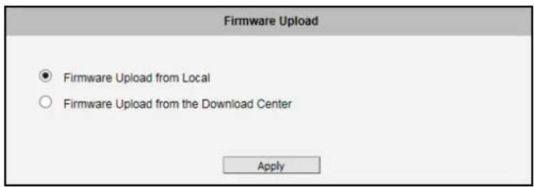
text_image
Firmware Upload ● Firmware Upload from Local ○ Firmware Upload from the Download Center ApplyFirmware Upload from Local
To upload the firmware manually, download the firmware image file, which contains the file extension ".upg", from the website. Choose "Firmware Upload from Local" and press the Apply button.
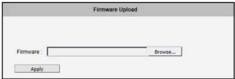
text_image
Firmware Upload Firmware : Browse... ApplyClick Browse to select the downloaded firmware image file. Click the Apply button to start the upload.
Once the process is finished, you will get an "OK" message and the system will reboot itself.
Firmware Upload from the Download Center
To upgrade the firmware automatically, choose "Firmware Upload from the Download Center" and press the Apply button. The camera will automatically search the latest firmware version. Click the Upload button to start the upload. Once the process is finished, you will get an "OK" message and the system will reboot itself.
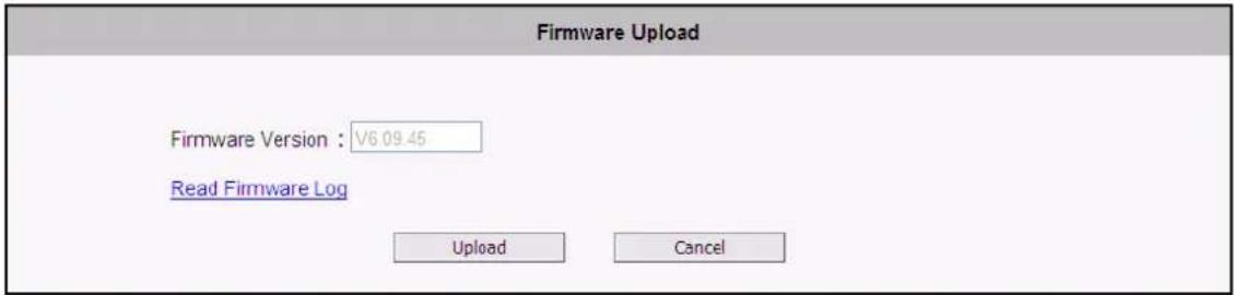
text_image
Firmware Upload Firmware Version : V6.09.45 Read Firmware Log Upload CancelIf the camera found the running version is already the latest one, a message will pop up and firmware upload is not needed.

text_image
Firmware Upload The firmware is the latest firmwareIf the camera failed to connect to the internet or the DNS server is not set correctly, a warning message will pop up, please examine your IP address setting and the DNS server settings.
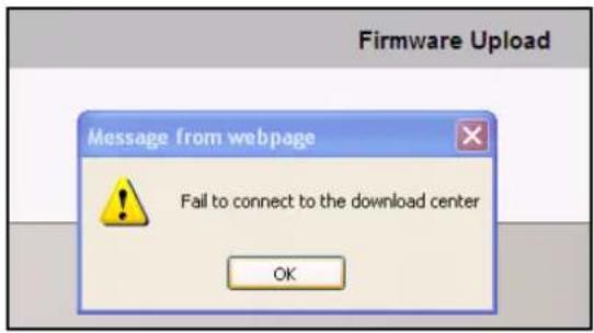
text_image
Firmware Upload Message from webpage Fail to connect to the download center OKSave & Reboot
Save & Reboot
The Save & Reboot section allows saving the settings and rebooting the camera remotely. This is critical because some settings might not take effect before save & reboot.
Save & Reboot
Click apply to save all settings and reboot this device.
Please wait 30 seconds for system reboot. And the window will close in 3 seconds.
Apply
Logout
Logout
Clicking this item allows you to log out of the IP device. Be sure to logout
this IP device once you have completed all the tasks via Web Configurator.
Troubleshooting
Although the default settings of the camera are ideal for 90% of the cases, there may be some rare cases when the settings need to be adjusted or the device has to be examined. The following section provides easy troubleshooting solutions for most cases. In some occasions, the unexpected symptoms may be the result of selecting the product that is not suitable for given environment.
For more detailed explanations and instructions of each situation, please refer to the complete
Troubleshooting Guide at http://www.acti.com/kb/detail.asp?KB_ID=KB20130130001
| Image Quality Troubleshooting | |
| Problem | Solution |
| Motion blur | Increase shutter speed |
| Blurry image | Auto Focus: Refocus button; Manual focus: adjust manually |
| Too narrow DoF | Reduce aperture size, widen the viewing angle, install camera farther from objects |
| Too narrow viewing angle | Vari-focal lens: widen the viewing angle; Zoom lens: press the zoom-out button; Fixed lens: replace it with wide angle fixed lens or choose another model with wide angle lens |
| Objects too small | Increase video resolution; zoom-in (zoom lens) or adjust lens to telephoto position (vari-focal); Install the camera closer to target; Change to the lens with longer focal length; Change the camera model with higher resolution or longer focal length |
| Underexposed image | Use Auto Exposure Mode and increase AE Reference Target; set the Slowest Auto Shutter Speed to slowest possible (1/5s); Add external light source to illuminate the area the camera is shooting |
| Overexposed image | Use Auto Exposure Mode and reduce AE Reference Target if necessary |
| Noise | Enable DNR; Enlarge the aperture; Lower AE Reference Target in Auto Exposure mode; Lower the Exposure Gain in Manual Exposure mode; Lower video resolution; Add extra visible or IR lights |
| Blocking & mosaic | Increase the bitrate |
| Wrong colors or color rolling | Manually correct the colors by using white paper “Hold” button in Auto White Balance mode; Adjust the camera's position or viewing direction; Adjust the light source |
| Black image | Make sure there is sufficient light; Make sure the Day/Night Mode and IR LED Control are both in Auto mode; Make sure that the “Switch from Day mode to Night mode” does NOT have the most extreme value – 100; Manual iris: open the iris by rotating the ring towards “O”; Remove the protective cap of the lens during installation |
| IR light reflection | Make sure the dome or bullet cover is tightly mounted; Reduce the AE reference target in Auto Exposure mode; Reduce the Exposure Gain in Manual Exposure mode |
| Streaming Quality Troubleshooting | |
| Frame Rate Too Low at Night | In auto exposure mode, set the Slowest Auto Shutter Speed to be not slower than the interval of frames; In manual exposure mode, set the Shutter Speed to be not slower than the interval of frames |
| Latency | Use dual stream (stream 1 for recording, stream 2 for live view); Lower the bitrate; Lower the resolution (if acceptable for user); Check the cable quality; Make sure to use industrial grade switches and routers; Check the NVR server & client PC requirements from NVR manual |
| Jitter | Use the NVR that has the video smoothening algorithm for live view and playback |
| Dropped Frames | Use the Playback function of NVR – use frame-by-frame validation of jitter-looking sections, to see if any frames are dropped; To troubleshoot the data switch/router and VMS computer, you may also ask for assistance from technical support team of camera manufacturer |

ACTi
Connecting Vision
Copyright © 2015, ACTi Corporation All Rights Reserved
7F, No. 1, Alley 20, Lane 407, Sec. 2, Ti-Ding Blvd., Neihu District, Taipei, Taiwan 114, R.O.C.
TEL: +886-2-2656-2588 FAX: +886-2-2656-2599
Email: sales@acti.com