
RS3DC040 - Regulator INTEL - Free user manual and instructions
Find the device manual for free RS3DC040 INTEL in PDF.


| Product Type | 12Gb/s Intel® RAID Controller RS3DC040 |
| Brand | Intel |
| Model | RS3DC040 |
| Category | RAID Controller |
| Form Factor | Low-profile PCI Express adapter card (68.90 mm x 167.65 mm) |
| Weight | Approximately 200 g (estimated) |
| Power Consumption | 13.95 W (idle) / 16.15 W (stress) at +3.3V and +12V |
| Host Interface | PCIe 3.0 x8 (up to 8 GT/s per lane) |
| SAS/SATA Ports | 4 internal ports via one SFF-8643 mini-SAS HD-4i connector |
| Supported Devices | Up to 15 SAS or SATA III devices per port (total up to 240 with expanders) |
| RAID Levels | 0, 1, 5, 6, 10, 50, 60 |
| Cache Memory | 1 GB DDR3 1866 MT/s with RAID Maintenance Free Backup support |
| Data Transfer Rate | Up to 12 Gb/s per SAS port; up to 6 Gb/s per SATA III port |
| Processor | LSISAS3108 RAID-on-Chip (ROC) |
| Architecture | Fusion-MPT™ |
| Operating Temperature | +10°C to +55°C (without battery backup unit) |
| Airflow Requirement | Minimum 200 linear feet per minute (LFPM) |
| Safety Compliance | UL 94 V0 flammability rating, SELV 42.4V limit |
| Maintenance & Cleaning | Keep controller free of dust; ensure adequate airflow; do not attempt internal repairs |
| Spare Parts & Reparability | Not user-serviceable; contact Intel support for repairs or replacement |
Frequently Asked Questions - RS3DC040 INTEL
User questions about RS3DC040 INTEL
0 question about this device. Answer the ones you know or ask your own.
Ask a new question about this device
Download the instructions for your Regulator in PDF format for free! Find your manual RS3DC040 - INTEL and take your electronic device back in hand. On this page are published all the documents necessary for the use of your device. RS3DC040 by INTEL.
USER MANUAL RS3DC040 INTEL
12Gb/s Intel® RAID Controllers User Guide
Intel Order Number: H21668-001
DISCLAIMER
IINFORMATION IN THIS DOCUMENT IS PROVIDED IN CONNECTION WITH INTEL PRODUCTS. NO LICENSE, EXPRESS OR IMPLIED, BY ESTOPPEL OR OTHERWISE, TO ANY INTELLECTUAL PROPERTY RIGHTS IS GRANTED BY THIS DOCUMENT. EXCEPT AS PROVIDED IN INTEL'S TERMS AND CONDITIONS OF SALE FOR SUCH PRODUCTS, INTEL ASSUMES NO LIABILITY WHATSOEVER AND INTEL DISCLAIMS ANY EXPRESS OR IMPLIED WARRANTY, RELATING TO SALE AND/OR USE OF INTEL PRODUCTS INCLUDING LIABILITY OR WARRANTIES RELATING TO FITNESS FOR A PARTICULAR PURPOSE, MERCHANTABILITY, OR INFRINGEMENT OF ANY PATENT, COPYRIGHT OR OTHER INTELLECTUAL PROPERTY RIGHT.
A "Mission Critical Application" is any application in which failure of the Intel Product could result, directly or indirectly, in personal injury or death. SHOULD YOU PURCHASE OR USE INTEL'S PRODUCTS FOR ANY SUCH MISSION CRITICAL APPLICATION, YOU SHALL INDEMNIFY AND HOLD INTEL AND ITS SUBSIDIARIES, SUBCONTRACTORS AND AFFILIATES, AND THE DIRECTORS, OFFICERS, AND EMPLOYEES OF EACH, HARMLESS AGAINST ALL CLAIMS COSTS, DAMAGES, AND EXPENSES AND REASONABLE ATTORNEYS' FEES ARISING OUT OF, DIRECTLY OR INDIRECTLY, ANY CLAIM OF PRODUCT LIABILITY, PERSONAL INJURY, OR DEATH ARISING IN ANY WAY OUT OF SUCH MISSION CRITICAL APPLICATION, WHETHER OR NOT INTEL OR ITS SUBCONTRACTOR WAS NEGLIGENT IN THE DESIGN, MANUFACTURE, OR WARNING OF THE INTEL PRODUCT OR ANY OF ITS PARTS.
Intel may make changes to specifications and product descriptions at any time, without notice. Designers must not rely on the absence or characteristics of any features or instructions marked "reserved" or "undefined". Intel reserves these for future definition and shall have no responsibility whatsoever for conflicts or incompatibilities arising from future changes to them. The information here is subject to change without notice. Do not finalize a design with this information.
The products described in this document may contain design defects or errors known as errata which may cause the product to deviate from published specifications. Current characterized errata are available on request.
Copies of documents which have an order number and are referenced in this document, or other Intel literature, may be obtained by calling 1-800-548-4725, or go to: http://www.intel.com/design/literature.htm.
Intel warranties that this product will perform to its published specifications. However, all computer systems are inherently subject to unpredictable system behavior under various environmental and other conditions.
This product is not intended to be the sole source for any critical data and the user must maintain a verified backup. Failure to do so or to comply with other user notices in the product user guide and specification documents may result in loss of or access to data.
This is the primary user guide for the 12Gb/s Intel ^® RAID Controllers. It contains installation instructions and specifications.
Audience
The people who benefit from this document are:
- 12Gb/s Intel ^ RAID Controller users
Organization
This document includes the following chapters and glossary:
- Chapter 1 provides a general overview of the 12Gb/s Intel ^ RAID Controller.
- Chapter 2 provides the instructions on how to install the 12Gb/s Intel® RAID Controller.
- Chapter 3 describes the characteristics of the 12Gb/s Intel ^ RAID Controller.
- Glossary describes how to use the command-line-driven SAS-3 Integrated RAID configuration utility (SAS3IRCU) to create and manage Integrated RAID volumes on Intel SAS-3 controllers.
Related Publication
This is the primary hardware guide for the 12Gb/s Intel ^® RAID Controllers. It contains installation instructions and specifications to aid in the configuration and use of this product.
Table of Contents
Preface ....iii
Audience .... iii
Organization iii
Related Publication ....iii
12Gb/s Intel ^® RAID Controller Overview ...... 1
Overview ....1
12Gb/s Intel ^® RAID Controllers with Support for RAID Maintenance Free Back Units .2
SAS/SATA Standards and Communication Protocols ....2
General Description 2
12Gb/s Intel® RAID Controller Detailed Descriptions 3
Intel ^® RAID Controller RS3WC080 3
Intel® RAID Controller RS3DC040 and RS3DC080 3
Configuration Scenarios 3
Benefits of the SAS Interface 4
PCI Express Architecture 5
Operating System Support 5
Summary of 12Gb/s Intel ^® RAID Controller Characteristics ......6
SAS Features 7
SAS Array Limitations ....7
SATA III Features 8
PCI Express Performance 9
Usability Features 9
Flexibility Features 9
Drive Roaming 10
Drive Migration 10
Hardware Specifications 11
12Gb/s Intel® RAID Controller Hardware Installation 13
Requirements 13
Quick Installation 13
Detailed Installation 14
After Installing the RAID Controller 16
SAS Device Cables and Connectors ....16
Connecting a RAID Controller with Internal Port Connectors by Cable to Internal Drives 18
12Gb/s Intel ^® RAID Controller Characteristics ...... 21
12Gb/s Intel ^® RAID Controller Family 21
Intel ^® RAID Controller RS3WC080 21
Intel® RAID Controller RS3DC040 and RS3DC080 23
12Gb/s Intel ^® RAID Controller Characteristics 27
Technical Specifications 28
RAID Controller Specifications 28
Array Performance Features 29
Fault Tolerance 29
Electrical Characteristics 30
Safety Characteristics 32
Glossary 33
List of Figures
Figure 1. Example of an Intel SAS Direct-Connect Application.... 4
Figure 2. Example of an Intel SAS RAID Controller Configured with an LSISASx12 Expander 4
Figure 3. Example of the Intel ^® RAID Controller RS3DC080 Installation in a PCIe Slot..... 15
Figure 4. Internal SAS Cable for Connection to SAS Drives, SATA II Drives, or SATA III Drives 17
Figure 5. SATA III Connectors ...... 17
Figure 6. SAS Plugs, SATA Plugs, and SAS Backplane Receptacle Connector.... 18
Figure 7. Connecting the Intel ^® RAID Controller RS3DC080 to a Drive ..... 19
Figure 8. Card Layout for the Intel ^® RAID Controller RS3WC080 22
Figure 9. Card Layout for the Intel® RAID Controller RS3DC080 24
List of Tables
Table 1. 12Gb/s Intel ^® RAID Controller Features .....6
Table 2. 12Gb/s Intel ^® RAID Controller Array Limitations .....8
Table 3. 12Gb/s Intel ^® RAID Controller Hardware Specifications .....12
Table 4. Jumpers and Connectors on the Intel ^® RAID Controller RS3WC080 .....22
Table 5. Jumpers and Connectors on the Intel ^® RAID Controller RS3DC080 .....24
Table 6. 12Gb/s Intel ^® RAID Controller Characteristics .....27
Table 7. RAID Controller Specifications .....28
Table 8. Array Performance Features ......29
Table 9. Fault Tolerance Features ......30
Table 10. Power Supply for the Intel ^® RAID Controller RS3WC080 ....30
Table 11. Power Supply for the Intel ^® RAID Controller RS3DC0x0 ....31
1 12Gb/s Intel Overview
® RAID Controller
This document is the primary reference and user's guide for the Intel® RAID Controllers based on the 12Gb/s SAS/SATA RAID-on-a-chip (ROC) devices. This document contains complete installation instructions and specifications for these RAID controllers.
Overview
The 12Gb/s Intel ^® RAID Controllers are high-performance intelligent PCIe-to-SATA+SAS controllers with RAID control capability. The 12Gb/s Intel ^® RAID Controllers provide reliability, high-performance, and fault-tolerant drive subsystem management. They are an ideal RAID solution for the internal storage of workgroup, departmental, and enterprise systems. The 12Gb/s Intel ^® RAID Controllers offer a cost-effective way to implement RAID in a server.
SAS technology brings a wealth of options and flexibility with the use of SAS devices and SATA devices within the same storage infrastructure. However, SAS devices and SATA devices bring individual characteristics that make each one a more suitable choice depending on your storage needs. The 12Gb/s Intel ^® RAID Controller gives you the flexibility to combine these two similar technologies on the same controller, within the same enclosure, and in the same virtual drive.
Note: Carefully assess any decision to mix SAS drives and SATA drives within the same virtual drive. Although you can mix drives, the practice is strongly discouraged.
Intel offers a family of 12Gb/s Intel ^® RAID Controllers that address the needs for both internal and external solutions. The 12Gb/s Intel ^® RAID Controllers are based on the LSI first-to-market SAS IC technology and proven MegaRAID technology. As second-generation PCIe RAID controllers, these controllers address the growing demand for increased data throughput and scalability requirements across midrange and enterprise-class server platforms. These controllers provide these features:
• 12 Gb/s Serial Attached SCSI (SAS) performance
- 6 Gb/s SATA III performance
• Eight-lane, 8 GT/s PCIe host interface
12Gb/s Intel ^® RAID Controllers with Support for RAID Maintenance Free Back Units
The Intel ^® RAID Controller RS3DC0x0 supports the RAID Maintenance Free Backup Unit that protects the integrity of the cached data on Intel ^® Integrated RAID Modules by offloading the data stored in the RAM cache to NAND flash during a power loss event. And it eliminates the need for lithium ion (Li-ion) batteries traditionally used to protect DRAM cache memory on RAID controllers.
SAS/SATA Standards and Communication Protocols
The 12Gb/s Intel ^® RAID Controllers support the ANSI Serial Attached SCSI standard, version 3.0. In addition, the controller supports the SATA III protocol defined by the Serial ATA specification, version 3.0. Supporting both the SAS interface and the SATA interface, the SAS controller is a versatile controller that provides the backbone of both server and high-end workstation environments.
Each port on your RAID controller supports SAS devices, SATA devices, or both, by using the following protocols:
- SAS Serial SCSI Protocol (SSP), which enables communication with other SAS devices
• SATA, which enables communication with other SATA devices - Serial Management Protocol (SMP), which communicates topology management information directly with an attached SAS expander device
- Serial Tunneling Protocol (STP), which enables communication with SATA devices through an attached expander
General Description
The 12Gb/s Intel ^® RAID Controllers bring 12.0 Gb/s Serial Attached SCSI and SATA III performance to host adapter, workstation, and server designs. The 12Gb/s Intel ^® RAID Controllers are based on the LSISAS3108 RAID On-a-Chip (ROC) device or the LSISAS3008 SAS chip.
The controllers support internal storage devices and external storage devices, which allow you to use a system that supports enterprise-class SAS drives and desktop-class SATA III drives. Each 12Gb/s Intel ^® RAID Controller can connect to drives directly and can use expanders to connect to additional drives. Simplified cabling between devices is an additional benefit.
These devices are compliant with the Fusion-MPT ^TM architecture and provides a PCIe x8 interface. Each port on the 12Gb/s Intel ^® RAID Controllers supports SAS devices, SATA devices, or both, using SSP, SMP, STP, and SATA. The SSP protocol enables the 12Gb/s Intel ^® RAID Controllers to communicate with other SAS devices. The SATA protocol enables the 12Gb/s Intel ^® RAID Controllers to communicate with SATA devices.
12Gb/s Intel ^® RAID Controller Detailed Descriptions
The 12Gb/s Intel ^® RAID Controllers are described in detail in the following subsections.
Intel ^® RAID Controller RS3WC080
The Intel ^® RAID Controller RS3WC080 is a PCIe 3.0 Low-Profile SAS Controller that controls eight internal SAS/SATA ports through two SFF-8643 mini-SAS HD-4i internal connectors.
Intel ^® RAID Controller RS3DC040 and RS3DC080
- The Intel ^ RAID Controller RS3DC040 is a PCIe 3.0 Low-Profile SAS Controller that controls four internal SAS/SATA ports through one SFF-8643 mini-SAS HD-4i internal connector.
- The Intel ^ RAID Controller RS3DC080 is a PCIe 3.0 Low-Profile SAS Controller that controls eight internal SAS/SATA ports through two SFF-8643 mini-SAS HD-4i internal connectors.
Configuration Scenarios
You can use the 12Gb/s Intel ^® RAID Controllers in three main scenarios:
- Low-end internal SATA configuration: In this configuration, use the RAID controller as a high-end SATA II or SATA III compatible controller that connects up to eight drives either directly or through a port expander. This configuration is mostly for low-end or entry servers. An out-of-band I²C bus provides enclosure management. Side bands of both types of internal SAS connectors support the SFF-8485 (SGPIO) interface.
- Midrange internal SAS configuration: This configuration is like an internal SATA configuration, but with high-end SAS drives. This configuration is more suitable for low-range to midrange servers.
- High-end external SAS/SATA configuration: This configuration is for external connectivity using SATA II drives, SATA III drives, SAS drives, or combinations of SATA and SAS drives. External enclosure management is supported through in-band, SCSI-enclosed storage. The configuration must support STP and SMP.
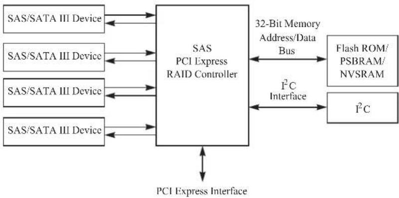
The following figure shows a direct-connect configuration. The Inter-IC (I²C) interface communicates with peripherals. The external memory bus provides a 32-bit memory bus, parity checking, and chip select signals for pipelined synchronous burst static random access memory (PSBRAM), nonvolatile static random access memory (NVSRAM), and Flash ROM.
Figure 1. Example of an Intel SAS Direct-Connect Application
flowchart
graph TD
    A["SAS/SATA III Device"] <--> B["SAS PCI Express RAID Controller"]
    C["SAS/SATA III Device"] <--> B
    D["SAS/SATA III Device"] <--> B
    E["SAS/SATA III Device"] <--> B
    F["SAS/SATA III Device"] <--> B
    B --> G["32-Bit Memory Address/Data Bus"]
    G --> H["Flash ROM/PSBRAM/NVSRAM"]
    B --> I["I²C Interface"]
    I --> J["I²C"]
    J --> K["PCI Express Interface"]
    K <--> B
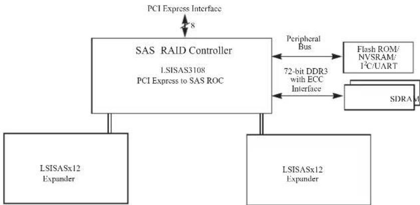
The following figure shows an example of a SAS RAID controller configured with an LSISASx12 expander that is connected to SAS drives, SATA III drives, or both.
Figure 2. Example of an Intel SAS RAID Controller Configured with an LSISASx12 Expander
flowchart
graph TD
    A["PCI Express Interface"] --> B["SAS RAID Controller"]
    B --> C["LSISAS3108 PCI Express to SAS ROC"]
    C --> D["LSISASx12 Expander"]
    C --> E["LSISASx12 Expander"]
    F["Peripheral Bus"] <--> G["Flash ROM/NVSRAM/1°C/UART"]
    F <--> H["SDRAM"]
    I["72-bit DDR3 with ECC Interface"] --> C
Benefits of the SAS Interface
SAS is a serial, point-to-point, enterprise-level device interface that leverages the proven SCSI protocol set. SAS is a convergence of the advantages of SATA, SCSI, and Fibre Channel, and it is the future mainstay of the enterprise and high-end workstation storage markets. SAS offers a higher bandwidth per pin than parallel SCSI, and it improves signal and data integrity.
The SAS interface uses the proven SCSI command set to ensure reliable data transfers, while providing the connectivity and flexibility of point-to-point serial data transfers. The serial transmission of SCSI commands eliminates clock-skew challenges. The SAS interface provides improved performance, simplified cabling, smaller connectors, lower pin count, and lower power requirements when compared to parallel SCSI.
The SAS controllers leverage a common electrical and physical connection interface that is compatible with Serial ATA technology. The SAS protocols and the SATA III protocols use a thin, 7-wire connector instead of the 68-wire SCSI cable or 26-wire ATA cable. The SAS/SATA III connector and cable are easier to manipulate, allow connections to smaller devices, and do not inhibit airflow. The point-to-point SATA III architecture eliminates inherent difficulties created by the legacy ATA master-slave architecture, while maintaining compatibility with existing ATA firmware.
PCI Express Architecture
PCIe is a local bus system designed to increase data transfers without slowing down the central processing unit (CPU). You can install the 12Gb/s Intel ^® RAID Controllers in PCIe computer systems with a standard bracket type. With these controllers in your system, you can connect SAS devices and SATA devices over the bus.
Note: Some PCIe slots support PCIe graphics cards only; RAID controllers installed in these PCIe slots do not function.
PCIe goes beyond the PCI specification in that it is intended as a unifying I/O architecture for various systems: desktops, workstations, mobile devices, servers, communications, and embedded devices.
Operating System Support
The 12Gb/s Intel ^® RAID Controllers support the following operating systems:
- Microsoft Windows 2003* R2 SP2, Windows Vista* SP2, Windows 7* Client SP1, Windows 8*, Windows 2008* SP2, Windows 2008* R2 SP1, and Window Server 2012*
- Red Hat* Linux
- SuSE* SLES
- Ubuntu* Linux
- VMware*
- Solaris*
- XenServer*
- Oracle* Enterprise Linux (OEL)
Refer to the Intel SAS Device Driver Installation User Guide for more information about the drivers. To download the latest operating system drivers, go to http://www.intel.com.
The 12Gb/s Intel ^® RAID Controllers use Fusion-MPT architecture for all major operating systems, thinner drivers, and better performance.
Summary of 12Gb/s Intel® RAID Controller Characteristics
This section summarizes the features and benefits offered by the 12Gb/s Intel ^® RAID Controllers. It contains information on SAS features, SATA features, PCI performance, integration, usability, and flexibility.
The 12Gb/s Intel ^® RAID Controllers have the following features.
Table 1. 12Gb/s Intel ^® RAID Controller Features
| Feature RS3WC080 RS3DC040 RS3DC080 | |||
| LSI SAS ROC or IOC LSI3008 LSI3108 LSI3108 | |||
| PCIe x8 lane width (with support for x16 connectors) Yes Yes Yes | |||
| PCIe performance up to 8GT/s per lane Yes Yes Yes | |||
| 1-GB DDR3 1866-MT/s onboard SDRAM No Yes Yes | |||
| Number of Internal 4-port SAS Connectors | 2 | 1 | 2 |
| Supported RAID levels | 0, 1, 5, 10, 50 | 0, 1, 5, 6, 10, 50, 60 | 0, 1, 5, 6, 10, 50, 60 |
| Advanced array configuration and management utilities | Yes Yes Yes | ||
| Support for global hot spares and dedicated hot spares | Yes Yes Yes | ||
| Support for user-defined strip sizes: 8, 16, 32, 64, 128, 256, 512, or 1024 KB | Yes Yes Yes | ||
| Advanced array configuration and management utilities offer these capabilities:• Online capacity expansion to add space to an existing drive or a new drive• Online RAID level migration• Drive migration• Drive roaming• No reboot necessary after expansion• Load balancing• Media scan | Yes Yes Yes | ||
| User-specified rebuild rate (specifying the percentage of system resources to use from 0 percent to 100 percent) | Yes Yes Yes | ||
| Nonvolatile random access memory (NVRAM) of 32 KB for storing RAID system configuration information; the MegaRAID SAS firmware is stored in flash ROM for easy upgrade. | Yes Yes Yes | ||
| Full MegaRAID Software Stack | No | Yes | Yes |
| iMR Software Stack Yes No No |
SAS Features
The 12Gb/s Intel ^® RAID Controllers support the following SAS features:
- They provide four fully independent PHYs or eight fully independent PHYs, depending on the controller.
- They support 12 Gb/s, 6Gb/s and 3Gb/s SAS data transfers per PHY.
• They support SMP to communicate topology-management information.
• They support SSP to enable communication with other SAS devices. - They support STP to enable communication with SATA devices through an attached expander.
• They provide a serial, point-to-point, enterprise-level storage interface. - They simplify cabling between devices.
- They provide a scalable interface that supports up to 240 devices through the use of expanders.
Note: The number of devices varies depending on the Intel ^® RAID Controller product. Check the Intel website, http://www.intel.com, for specific details about your product.
- They support wide ports that consist of two, three, or four PHYs within a single quad port.
- They support narrow ports consisting of a single PHY.
- They transfer data by using SCSI information units.
SAS Array Limitations
This section describes the array limitations of the 12Gb/s Intel ^® RAID Controllers. These limitations include the number of drives supported per controller, the maximum number of drives per controller, and the maximum number of virtual drives allowed per controller.
The following table lists the array limitations for the 12Gb/s Intel ^® RAID Controllers.
Table 2. 12Gb/s Intel ^® RAID Controller Array Limitations
| Specification | Intel® RAID Controller RS3WC080 | Intel® RAID Controller RS3DC040/RS3DC080 |
| Maximum virtual drives per controller 64 64 | ||
| Maximum drive groups per controller 128 128 | ||
| Maximum virtual drives per drive group 16 16 | ||
| Maximum drives per drive group 32 32 | ||
| Maximum drives per controller 240 240 | ||
| Maximum hot spares per controller 240 240 | ||
| Maximum spans per virtual drive | 8 | 8 |
| Maximum enclosures per portA | 10 10 | |
| Number of port connectors | 5 | 5 |
A. The number assumes one storage enclosure processor (SEP) per enclosure.
The maximum numbers in the previous table depend on how many physical devices you have connected to the RAID controller. For example, the maximum number of drive groups is equal to the number of drives that are supported by the controller. Thus, for the Intel ^® RAID Controller RS3DC0x0, the maximum number of drive groups per controller is 240, which is based on the maximum number of physical devices that you can connect. In addition, the maximum number of hot spares per controller is equal to the maximum number of drives per controller.
Although you can have up to 16 virtual drives per drive group, and up to 128 drive groups on most of the controllers, a limit of 64 virtual drives exists on those controllers.
These RAID controllers support 64-bit logical block addressing (LBA), which makes it possible to connect a large number of drives to the RAID controller, directly and through expanders. However, the actual number of drives that you can attach depends on the limits listed in this table rather than by actual RAID volume capacity.
SATA III Features
The following list describes the SATA III features of the RAID controllers:
• They support SATA III data transfers of 6Gb/s for LSISAS3108-based controllers.
• They support STP data transfers of 3Gb/s.
- They provide a serial, point-to-point storage interface.
- They simplify cabling between devices.
• They eliminate the master-slave construction used in parallel ATA.
• They permit addressing of multiple SATA targets through an expander.
- They permit multiple initiators to address a single target (in a fail-over configuration) through an expander.
PCI Express Performance
The following list describes the PCIe performance features of the RAID controllers:
- They provide a PCIe interface that does the following:
— Supports a dedicated PCIe bus.
— Supports x8 lane configuration.
— Supports transfer rates of up to 8GT/s per lane.
— Complies with the PCI Express specification, Revision 3.0, and the Serial ATA specification, version 3.0.
• They provide unequaled performance through the Fusion-MPT architecture.
- They provide high throughput and low CPU utilization to offload the host processor.
Usability Features
The following list describes the usability features of the RAID controllers:
• They simplify cabling with point-to-point, serial architecture.
- They support smaller, thinner cables that do not restrict airflow.
- They provide drive spin-up sequencing control.
- They provide one LED signal for each PHY to indicate link activity (this is a fault LED only for controllers with internal port connectors).
- They provide an I ^2 C interface for enclosure management.
• They support the internal SAS Sideband signal SFF-8485 (SGPIO) interface.
Flexibility Features
These features increase the flexibility of the RAID controllers:
- They support a Flash ROM interface, a nonvolatile static RAM (NVSRAM) interface, and a pipelined synchronous burst SRAM (PSBRAM) interface.
• They offer a flexible programming interface to tune I/O performance.
• They permit mixed connections to SAS targets or SATA III targets.
- They leverage compatible connectors for SAS connections and SATA III connections.
- They permit grouping of up to four PHYs in a single quad port to form a wide port.
- They permit programming of the World Wide Name.
Drive Roaming
Drive roaming occurs when the drives are changed to different ports on the same controller. When the drives are placed on different channels, the controller detects the RAID configuration from the configuration data on the drives.
Configuration data is saved in both the NVRAM on the RAID controller and on the drives attached to the controller. This action maintains the integrity of the data on each drive, even if the drives have changed their physical device ID.
Note: If you move a drive that is being rebuilt, the rebuild operation restarts; it does not resume from the stopping point.
Follow these steps to use the drive roaming feature:
-
Turn off the power to the server and all drives, enclosures, and system components. Disconnect the power cords from the system.
-
Open the host system by following the instructions in the host system technical documentation.
-
Move the drives to different positions on the backplane to change the targets.
-
Determine the SAS target requirements.
-
Perform a safety check.
a. Make sure that the drives are inserted correctly.
b. Close the cabinet of the host system.
-
Reconnect the power cords to the system.
-
Turn on the power to the system.
The controller then detects the RAID configuration from the configuration data on the drives.
Drive Migration
Drive migration is the transfer of a set of drives in an existing configuration from one controller to another. The drives must remain on the same channel and must be reinstalled in the same order as in the original configuration. The controller to which you migrate the drives cannot have an existing configuration.
Note: Partial configurations, which include individual virtual drives, can be migrated.
Note: Drive roaming and drive migration cannot be supported at the same time.
Follow these steps to migrate drives:
- Make sure that you clear the configuration on the system to which you migrate the drives to prevent a configuration data mismatch between the drives and the NVRAM.
Note: When you migrate drives, move only the drives that make up the virtual drive (not all of the drives in a drive group), so that you do not see an NVRAM mismatch error (providing a configuration is on the destination controller). The NVRAM mismatch error appears only if you move all of the drives to the other controller.
-
Turn off power to the server and all drives, enclosures, and system components. Disconnect the power cords from the systems.
-
Open the host system by following the instructions in the host system technical documentation.
-
Either remove the SAS cable connectors from the internal drives, or remove the shielded cables from the external drives that you want to migrate.
a. Make sure that pin 1 on the cable matches pin 1 on the connector.
b. Make sure that the SAS cables conform to all SAS specifications.
-
Remove the drives from the first system, and insert them into the drive bays on the second system.
-
Connect the SAS cables to the drives in the second system.
-
Determine the SAS target requirements.
-
Perform a safety check.
a. Make sure that all of the cables are attached correctly.
b. Make sure that the RAID controller is installed correctly.
c. Close the cabinet of the host system.
-
Reconnect the power cords to the system.
-
Turn on the power to the system.
The controller detects the RAID configuration from the configuration data on the drives.
Hardware Specifications
You can install the 12Gb/s Intel ^® RAID Controllers in a computer with a motherboard that has a PCIe slot. The following table describes the hardware configuration features for the 12Gb/s Intel ^® RAID Controllers.
Table 3. 12Gb/s Intel ^® RAID Controller Hardware Specifications
| Specification Intel | ® RAID Controller RS3WC080 | Intel® RAID Controller RS3DC040/RS3DC080 |
| RAID levels 0, 1, 5, 10, 50 0, 1, 5, 6, | 10, 50, 60 | |
| Devices supported per port Up to 15 | SAS devices or SATA III devices (such as drives and expanders) | Up to 15 SAS devices or SATA III devices (such as drives and expanders) |
| Number of ports Eight ports through | two SFF-8643mini-SAS HD-4i connectors | Intel® RAID Controller RS3DC040 – Four ports through one SFF-8643 mini-SAS HD-4i connectorIntel® RAID Controller RS3DC080 – Eight ports through two SFF-8643 mini-SAS HD-4i connectors |
| Data transfer rate | Up to 12Gb/s per PHY | Up to 12Gb/s per PHY |
| Bus PCIe 3.0 PCIe 3.0 | ||
| Cache function Write-through, non-read-ahead, cache I/O, direct I/O | Write-back, write-through, non-read-ahead, read-ahead, cache I/O, direct I/O | |
| Multiple virtual drives per controller | Up to 64 (this value is dependent on the firmware) | Up to 64 (this value is dependent on the firmware) |
| Online capacity expansion Yes Yes | ||
| Dedicated and global hot spares Yes | Yes | |
| Hot-swap devices supported | Yes Yes | |
| Non-drive devices supported | Yes Yes | |
| Mixed-capacity drives supported Yes | Yes | |
| Number of internal connectors | Two SFF-8643 mini-SAS HD-4i connectors | Intel® RAID Controller RS3DC040 – One SFF-8643 mini-SAS HD-4i connectorIntel® RAID Controller RS3DC080 – Two SFF-8643 mini-SAS HD-4i connectors |
| Hardware exclusive OR (XOR) assistance | Yes Yes | |
| Direct I/O | Yes Yes | |
| Architecture | Fusion-MPT | Fusion-MPT |
2 12Gb/s Intel ^® RAID Controller Hardware Installation
Requirements
The following items are required to install a 12Gb/s Intel ^® RAID Controller:
• A 12Gb/s Intel ^ RAID Controller
- A host system with an available x8 PCIe 3.0 slot
Note: These controllers also work in PCI Express first generation slots. The PCI Express software is backward compatible with previous revisions of the PCI bus and the PCI-X bus.
- The necessary internal cables, external cables, or both
• SAS drives or SATA drives
Note: Make sure to use an uninterruptible power supply.
Quick Installation
The following steps quickly install your 12Gb/s Intel ^® RAID Controller. These steps are for experienced computer users or installers. Detailed Installation contains the steps for all other users to follow.
- Turn off the power to the system and all drives, enclosures, and system components, and disconnect the PC power cord.
- Open the cabinet of the host system by following the instructions in the host system technical documentation.
- Check the jumper settings to make sure that they are in the desired position. The jumpers are set at the factory, and you usually do not need to change them.
Note: See Chapter 3, 12Gb/s Intel ^® RAID Controller Characteristics, for detailed information about the jumpers and the connectors.
-
Install the 12Gb/s Intel ^ RAID Controller in the server, and connect SAS devices or SATA II devices to it. Make sure that the cables you use conform to all specifications.
-
Perform a safety check. a. Make sure that all cables are attached correctly.
b. Make sure that the RAID controller is installed correctly.
c. Close the cabinet of the host system.
-
Reconnect the power cords to the system.
-
Turn on the power to the system.
Make sure that the power is turned on to any external drives before the power is turned on to the host computer. If the computer is powered up before these devices, the devices might not be recognized.
Detailed Installation
This section provides detailed instructions on how to install your 12Gb/s Intel ^® RAID Controller.
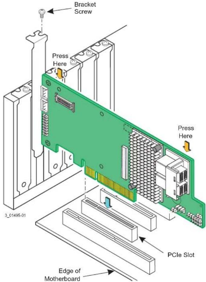
The figure in this section shows the installation of the Intel ^® RAID Controller RS3DC080 in a PCIe slot. You can install the Intel ^® RAID Controller RS3WC080 and the Intel ^® RAID Controller RS3DC040 in the same way.
- Unpack the 12Gb/s Intel ^ RAID Controller.
Unpack and remove your RAID controller. Inspect it for damage. If it appears damaged, contact your Intel Customer and Technical Support representative.
- Turn off the power to the system.
Turn off the power to the computer, and disconnect the AC power cord. Remove the computer cover. Refer to the system documentation for instructions. Before you install the controller, make sure that the computer is disconnected from the power and from any networks.
- Review the RAID controller jumpers and connectors.
The jumpers are set at the factory, and you usually do not need to change them. See Chapter 3, 12Gb/s Intel ^® RAID Controller Characteristics, for diagrams of the 12Gb/s Intel ^® RAID Controllers that show their jumpers and connectors.
- Install the RAID controller.
Select a PCIe slot, and align the controller's PCIe bus connector to the slot, as shown in the following figure. Press down gently, but firmly, to make sure that the card is seated correctly in the slot. Secure the bracket to the computer chassis with the bracket screw.
Note: If your RAID controller has a battery backup unit (BBU) attached, do not press down on the BBU when you insert the card.
Note: This RAID controller is a PCIe x8 card, and it can operate in x8 or x16 slots. Some PCIe slots, however, support only PCIe graphics cards; if a RAID controller is installed in one of these slots, the RAID controller will not
function. Refer to the guide for your motherboard for information about the PCIe slot.
Figure 3. Example of the Intel® RAID Controller RS3DC080 Installation in a PCIe Slot
- Configure and install the SAS devices, the SATA devices, or both in the host computer case.
Refer to the documentation for the devices for any pre-installation configuration requirements.
- Connect the RAID controller to the devices.
Use SAS cables to connect SAS devices, SATA devices, or both to the 12Gb/s Intel® RAID Controller. See SAS Device Cables and Connectors for SAS cable and connector information. See Connecting a RAID Controller with Internal Port Connectors by Cable to Internal Drives for information about connecting the controller to the drives.
The maximum cable length is 10 meters (393.37 in.). You can connect one device per SAS PHY unless you use an expander.
System throughput problems can occur if the SAS cables are not the correct type. To minimize the potential for problems, use the following guidelines:
— Use cables no longer than 10 meters (393.37 in.). (Use shorter cables, if possible.)
— Use cables that meet the SAS specification.
— Route the SAS cables carefully.
- Turn on the power to the system.
Reinstall the computer cover, and reconnect the AC power cords. Turn on power to the host computer. Make sure that the power is turned on to the SAS devices, SATA devices, or both before or at the same time that the power is turned on to the host computer. If the computer is powered on before these devices, the devices might not be recognized.
During boot, a BIOS message appears. The firmware takes several seconds to initialize. The configuration utility prompt times out after several seconds. The second portion of the BIOS message shows the 12Gb/s Intel ^® RAID Controller number, firmware version, and cache SDRAM size. The numbering of the controllers follows the PCI slot scanning order used by the host motherboard.
- Run the RAID BIOS Console Configuration Utility.
Run the RAID BIOS Console Configuration Utility to configure the drive groups and the virtual drives. When the message Press Ctrl+G for RAID BIOS Console appears on the screen, immediately press Ctrl+G to run the utility.
- Install the operating system driver.
The 12Gb/s Intel ^® RAID Controllers can operate under various operating systems. To operate under these operating systems, you must install the software drivers.
After Installing the RAID Controller
After you install the 12Gb/s Intel ^® RAID Controller, you must configure the controller and install the operating system driver. The Intel ^® RAID Software User Guide instructs you on the configuration options and how to set them on your 12Gb/s Intel ^® RAID Controller. The Intel SAS Device Driver Installation User Guide provides detailed installation instructions for operating system drivers.
SAS Device Cables and Connectors
This section describes the cables and the connectors used on the 12Gb/s Intel ^® RAID Controllers and provides step-by-step instructions for connecting SAS drives, SATA drives, or both to the 12Gb/s Intel ^® RAID Controller. The SAS protocol and the SATA protocol use a thin, 7-wire connector instead of the 68-wire SCSI cable or the 40-wire ATA cable.
Note: Use only straight SAS cables, not crossover SAS cables.
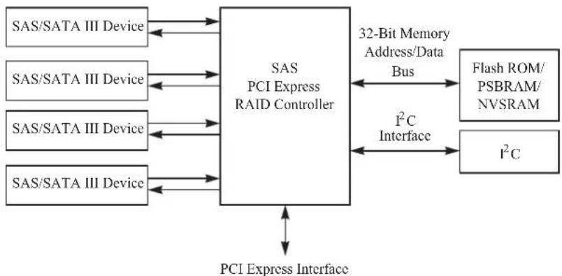
The following figure shows the SAS cable that connects the internal connectors on a SAS RAID controller to SAS drives, SATA drives, or both.
Figure 4. Internal SAS Cable for Connection to SAS Drives, SATA II Drives, or SATA III Drives
flowchart
graph TD
    A["SAS/SATA III Device"] --> B["SAS PCI Express RAID Controller"]
    C["SAS/SATA III Device"] --> B
    D["SAS/SATA III Device"] --> B
    E["SAS/SATA III Device"] --> B
    F["SAS/SATA III Device"] --> B
    B --> G["32-Bit Memory Address/Data Bus"]
    G --> H["Flash ROM/PSBRAM/NVSRAM"]
    B --> I["I²C Interface"]
    I --> J["I²C"]
    J --> K["PCI Express Interface"]
    K --> A
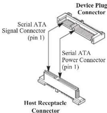
The following figure shows the SATA III device plug connector that connects a SAS RAID controller with internal connectors to the host receptacle connector on a backplane. A SATA III connector consists of a signal connector and a power connector.
Figure 5. SATA III Connectors
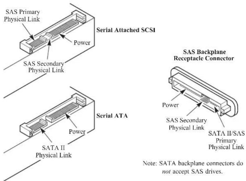
The following figure shows SAS connectors and SATA connectors on SAS drives and SATA drives, respectively. Cables connect internal connectors on the RAID controllers to connectors on SAS drives, SATA drives, or both. Both SAS drives and SATA drives can connect to SAS backplane receptacle connectors. The difference between the SAS connector and the SATA connector is the bridge between the SAS primary physical link and the power connector on the SAS controller, which the SATA connector does not have.
Note: SAS backplane connectors accept SAS drives or SATA drives, but SATA backplane connectors cannot accept SAS drives.
Figure 6. SAS Plugs, SATA Plugs, and SAS Backplane Receptacle Connector
The following subsection provides step-by-step instructions for connecting the 12Gb/s Intel® RAID Controllers to SAS drives and SATA drives, either directly or through an expander.
Connecting a RAID Controller with Internal Port Connectors by Cable to Internal Drives
This section provides step-by-step instructions for connecting the SAS cable from the internal SAS port connectors on the RAID controller to internal SAS drives and SATA drives.
Follow these steps to connect your RAID controller with internal SAS port connectors directly to SAS drives or SATA drives.
Note: The Intel ^ RAID Controller RS3DC080 is shown as an example. You can connect the Intel ^ RAID Controller RS3DC040 in the same way.
-
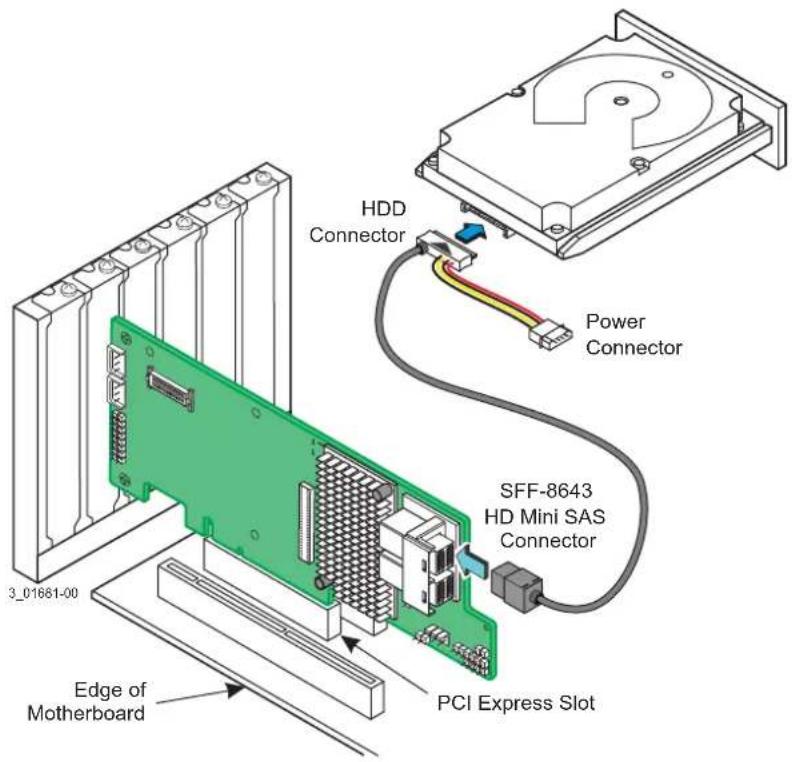
Insert the SFF-8643 internal mini-SAS HD-4i connector on the cable into a SFF-8643 internal mini-SAS HD-4i connector on the Intel ^® RAID Controller RS3DC080, as shown in the following figure.
-
Plug the HDD connector on the other end of the cable into the connector on the SAS drive or SATA drive.
-
If you have another drive, connect it to another plug on the internal cable.
You can connect other devices if the cable has more connectors.
Figure 7. Connecting the Intel ^® RAID Controller RS3DC080 to a Drive
3 12Gb/s Intel ^® RAID Controller Characteristics
12Gb/s Intel ^® RAID Controller Family
The 12Gb/s Intel ^® RAID Controllers are dual-PHY, SAS PCI Express RAID controllers and are used in a system with a PCI Express slot. PCI Express goes beyond the PCI specification in that it is intended as a unifying I/O architecture for various systems: desktops, workstations, mobile devices, servers, communications, and embedded devices.
The following subsections provide figures and connector information for the 12Gb/s Intel ^® RAID Controllers.
Intel ^® RAID Controller RS3WC080
The Intel ^® RAID Controller RS3WC080 is a low-profile SAS+SATA RAID controller that controls eight internal SAS/SATA ports through two SFF-8643 internal mini-SAS HD-4i connectors.
Intel ^® RAID Controller RS3WC080 – Board Layout and Jumper and Connector Information
This subsection provides the board layout, and the connector and jumper information for the Intel ^® RAID Controller RS3WC080. The following figure shows the jumpers and the connectors on the Intel ^® RAID Controller RS3WC080.
Note: Pin 1 on the headers and connectors is highlighted in red in this figure.
Figure 8. Card Layout for the Intel® RAID Controller RS3WC080
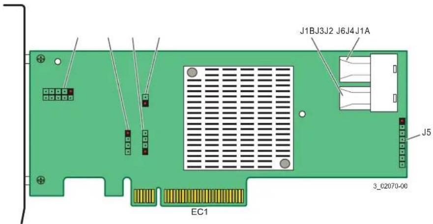
The following table describes the jumpers and the connectors on the Intel ^® RAID Controller RS3WC080.
Table 4. Jumpers and Connectors on the Intel® RAID Controller RS3WC080
| Jumper/ Connector | Type Description | |
| EC1 | Standard edge card connector | PCIe* x8 board edge connector |
| J1A SFF-86 | 43 mini-SAS HD-4i internal connector | x4 SAS Port 0 through Port 3 |
| J1B SFF-86 | 43 mini-SAS HD-4i internal connector | x4 SAS Port 4 through Port 7 |
| J2 10-pin header | Complex programmable logic device (CPLD)headerReserved for use. | |
| J3 2-pin connector | Modular RAID Key connector | Reserved for use. |
| J4 4-pin connector | On-board Serial Universal AsynchronousReceiver/Transmitter (UART) connectorReserved for use. | |
| J5 16-pin header | RISCwatch header | Reserved for use. |
| J6 2-pin header | Test header | Reserved for use. |
Intel ^® RAID Controller RS3DC040 and RS3DC080
The Intel ^® RAID Controller RS3DC040 is a low-profile SAS+SATA RAID controller that controls four internal SAS/SATA ports through one SFF-8643 internal mini-SAS HD-4i connectors.
The Intel ^® RAID Controller RS3DC080 is a low-profile SAS+SATA RAID controller that controls eight internal SAS/SATA ports through two SFF-8643 internal mini-SAS HD-4i connectors.
Intel® RAID Controller RS3DC080 – Board Layout and Jumper and Connector Information
This subsection provides the board layout, and the connector and jumper information for the Intel ^® RAID Controller RS3DC0x0. The following figure shows the jumpers and the connectors on the Intel ^® RAID Controller RS3DC080.
Note: The Intel ^ RAID Controller RS3DC040 is the same as the Intel ^ RAID Controller RS3DC080 except that the J5A1 connector on the Intel ^ RAID Controller RS3DC040 is a single internal port connector. The J5A1 connector on the Intel ^ RAID Controller RS3DC080 is a dual internal port connector.
Note: Pin 1 on the headers and connectors is highlighted in red in this figure.
Figure 9. Card Layout for the Intel® RAID Controller RS3DC080
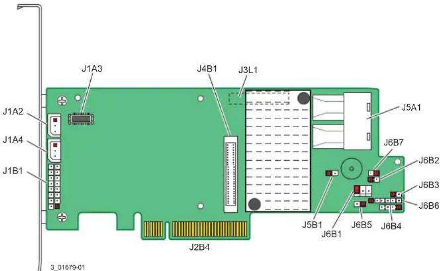
The following table describes the jumpers and the connectors on the Intel ^® RAID Controller RS3DC080.
Table 5. Jumpers and Connectors on the Intel ^® RAID Controller RS3DC080
| Jumper/ Connector | Type Description | |
| J1A2 3-pin | connector IPMI-style I | ^2C connector for Ports 4 to 7.Supports SCSI Enclosure Services (SES) over I^2C through an internal I^2C backplane cable. |
| J1A3 20-pin | connector Local RAID Maintenance F | Free Back Units connector.Connects the RMFBU directly to the RAID controller. |
| J1A4 3-pin | connector IPMI-style I | ^2C connector for Ports 0 to 3.Supports SES over I^2C through an internal I^2C backplane cable. |
J1B1 2x8-pin headerPorts 0 to 3Ports 4 to 7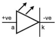 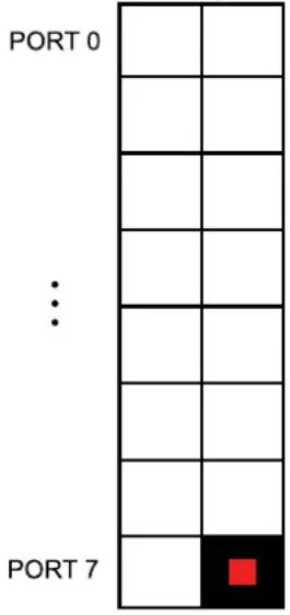 J1B13_01788-00 J1B13_01788-00 | Individual PHY and drive fault indication header.Connects to an LED that indicates whether a drive is in a fault condition. One LED exists per port. When lit, each LED indicates the corresponding drive has failed or is in the Unconfigured-Bad state.The LEDs function in a direct-attach configuration (no SAS expanders exist). Direct attach is defined as a maximum of one drive connected directly to each port.Note:The J5A1 connector on the Intel®RAID Controller RS3DC040 is a single internal port connector. | |
| J2B4 | Standard edge card connector | The interface between the RAID controller and the host system.Along with the PCIe interface, this connector provides power to the board and an I^2C interface connected to the I^2C bus for the Intelligent Platform Management Interface (IPMI). |
| J3L1 | 20-pin connector | Remote RAID Maintenance Free Back Units connector (on the backside of the controller).Connects the remote RMFBU to the RAID controller. |
| J4B1 70-pin | connector Flash Module DDR3 Interface. | Connects the controller to a flash module. |
| J5A1 Dual x4 | SAS Port 0 through Port 7internal connector | Two SFF-8643 mini-SAS HD-4i internal connectors.Connects the controller by cable to SAS drives or SATA drives. |
| J5B1 2-pin connector Test header. | Reserved for use. | |
| J6B1 3-pin header Premium Feature Key header. | Enables support for selected advanced features, such as Recovery, CacheCade*, FastPath, and SafeStore* disk encryption. | |
| J6B2 2-pin connector Default Serial boot ROM (SBR) header. | Reserved for use. | |
| J6B3 | 2-pin connector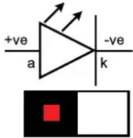 J6B33_01789-00 J6B33_01789-00 | Global hard disk drive (HDD) activity LED header.Connects to an LED that indicates activity on the drives connected to the controller. |
| J6B4 4-pin connector On-board Serial Universal AsynchronousReceiver/Transmitter (UART) connector. | Reserved for use. | |
J6B5 2-pin connector Global drive fault LED header.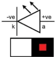 J6B53_01790-00 J6B53_01790-00 | Connects to an LED that indicates whether a drive is in a fault condition. | |
| J6B6 | 6-pin connector | Complex programmable logic device (CPLD) header.Reserved for use. |
J6B7 2-pin connector Cache write pending header.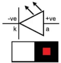 J6B73_01791-00 J6B73_01791-00 | Connector for an LED mounted on the system enclosure. The LED indicates that the data in the cache has yet to be written to the storage devices. | |
12Gb/s Intel ^® RAID Controller Characteristics
The following table shows the general characteristics for all 12Gb/s Intel ^® RAID Controllers.
Table 6. 12Gb/s Intel ^® RAID Controller Characteristics
| Flash ROMA | Serial EEPROMB | Data Transfer Rate SCSI Feature | SCSI Termination |
| Yes Yes Up to 12Gb/s per port for SAS and up to 6Gb/s per port for SATA III | Plug-and-Play Scatter/Gather Activity LED | ||
A. For boot code and firmware.
B. For BIOS configuration storage.
Each 12Gb/s Intel ^® RAID Controller ensures data integrity by intelligently validating the compatibility of the SAS domain. The 12Gb/s Intel ^® RAID Controllers use Fusion-MPT architecture, which allows for thinner drivers and better performance.
Technical Specifications
The design and implementation of the 12Gb/s Intel ^® RAID Controllers minimize electromagnetic emissions, susceptibility to radio frequency energy, and the effects of electrostatic discharge. The 12Gb/s Intel ^® RAID Controllers show the following marks and certifications:
- CE mark
• C-Tick mark
• FCC Self-Certification logo
• Canadian Compliance Statement - Korean MIC
• Taiwan BSMI - Japan VCCI
- CISPR Class B
The following hardware is compliant with CSA C22.2 No. 60950-1, UL 60950-1 First Edition-listed accessory, UL file number E257743:
- Intel ^ RAID Controller RS3DC040 (model 25420-00)
- Intel ^ RAID Controller RS3DC080 (model 25420-00)
RAID Controller Specifications
The following table lists the specifications for the 12Gb/s Intel ^® RAID Controllers.
Table 7. RAID Controller Specifications
| Specification | Intel®RAID ControllerRS3WC080, RS3DC040, and RS3DC080 |
| SAS controller and processor Intel | ®RAID Controller RS3WC080: LSISAS3008 Single SAS controllerIntel®RAID Controller RS3DC0x0: LSISAS3108 Single SAS controller |
| Operating voltage +3.3 V, +12 V | |
| Card size Intel | ®RAID Controller RS3WC080: Low-profile PCI Express adapter card size (68.90 mm x 152.35 mm)Intel®RAID Controller RS3DC0x0: Low-profile PCI Express adapter card size (68.90 mm x 167.65 mm) |
| Array interface to the host PCIe Rev. | 3.0 |
| PCI Express bus data transfer rate | Up to 8GT/s per lanex8 lane width |
| Serial port 4-pin RS232-compatible | connector (for manufacturing use only) |
| SAS bus speed 12Gb/s | |
| SAS ports SAS connectors with four | SAS ports each |
| Cache configuration The Intel | ®RAID Controller RS3DC0x0 supports the following cache configuration:1 GB – 72b arrangement (5) 128Mbx16, Double Data Rate III (DDR3) @ 1866 MHz with Intel®RAID Maintenance Free Backup support. |
| Size of flash ROM for firmware 16 MB | |
| NVRAM 32 KB for storing RAID configurations | |
Array Performance Features
The following table shows the array performance features for the 12Gb/s Intel ^® RAID Controllers.
Table 8. Array Performance Features
| Specification | Intel® RAID ControllerRS3WC080, RS3DC040, and RS3DC080 |
| PCI Express host data transfer rate 8GT/s per lane | |
| Drive data transfer rate 12Gb/s per lane | |
| Maximum scatter/gather I/O 80 elements | |
| Maximum size of I/O requests 6.4 MB in 64-KB strips | |
| Maximum queue tags per drive As many as the drive can accept | |
| Strip sizes | 8 KB, 16 KB, 32 KB, 64 KB, 128 KB, 256 KB, 512 KB, or 1 MB |
| Maximum number of concurrent commands | 255 |
Fault Tolerance
The following table lists the fault tolerance features for the 12Gb/s Intel ^® RAID Controllers.
Table 9. Fault Tolerance Features
| Specification | Intel® RAID ControllerRS3WC080, RS3DC040, and RS3DC080 |
| Support for SMART ^A | Yes |
| Drive failure detection Automatic | |
| Drive rebuild using hot spares Automatic | |
| Parity generation and checking Yes |
A. The Self Monitoring Analysis and Reporting Technology (SMART) detects up to 70 percent of all predictable drive failures. In addition, SMART monitors the internal performance of all motors, heads, and drive electronics.
Electrical Characteristics
This subsection provides the power supply requirements for the 12Gb/s Intel ^® RAID Controllers.
Power Supply Requirements for the Intel ^® RAID Controller RS3WC080
All power is supplied to the Intel ^® RAID Controller RS3WC080 through the PCIe 3.3V rails and the 12V rail. On-board switching regulator circuitry operating from the 3.3V rails and the 12V rail provides the necessary voltages. The following states determine the typical current consumption of the controller:
• State 1: During a hard reset
• State 2: During a drive stress test
• State 3: While sitting idle at the DOS prompt
The supply voltages are 12V ± 8 percent (from PCI edge connector only) and 3.3V ± 9 percent (from PCI edge connector only). The following table lists the power for the RAID controllers at peak and normal status.
Table 10. Power Supply for the Intel ^® RAID Controller RS3WC080
| Power Mode Power Mode Description DC Power (Watts) | ||
| Peak (on-max) Maximum 19.04 | ||
| On-Normal/Typical Typical | 13 | |
Note: The charging circuitry for the battery pack on the optional BBU battery-backed daughter card uses +12V. If the BBU daughter card is mounted, the following power consumption figures apply:
During trickle charging of the battery pack: Not applicable (no trickle charge for Li-ION). During fast charging of the battery pack: 230mA in +12V current.
Operating and Nonoperating Conditions for the Intel ^® RAID Controller RS3WC080
For the Intel ^® RAID Controller RS3WC080, the operating (thermal and atmospheric) conditions are as follows:
- Relative humidity range is 5 percent to 90 percent non-condensing.
- Airflow must be at least 75 linear feet per minute (LFPM) to avoid operating the LSISAS3008 processor above the maximum ambient temperature.
• Temperature range: 0^ C to +55^ C
The parameters for the nonoperating (such as storage and transit) environment for these controllers are as follows:
- Relative humidity range is 5 percent to 90 percent non-condensing.
• Temperature range: -45^ to +105^
Power Supply Requirements for the Intel ^® RAID Controller RS3DC0x0
All power is supplied to the Intel ^® RAID Controller RS3DC0x0 through the PCIe 3.3V rails and the 12V rail. On-board switching regulator circuitry operating from the 3.3V rails and the 12V rail provides the necessary voltages. The following states determine the typical current consumption of the controller:
• State 1: While sitting idle at the DOS prompt
• State 2: During a drive stress test
The supply voltages are 12V ± 8 percent (from PCI edge connector only) and 3.3V ± 9 percent (from PCI edge connector only). The following table lists the power supply for the RAID controllers for these two states at the different voltages.
Table 11. Power Supply for the Intel ^® RAID Controller RS3DC0x0
| PCI Edge Connector State 1 State 2 | ||
| 3.3V supply 793 mA 793 mA | ||
| +12V supply 915 mA 1090 mA | ||
| 3.3V auxiliary supply 1 mA 1 mA | ||
| Total Power 13.95 W 16.15 W |
Note: The charging circuitry for the battery pack on the optional BBU battery-backed daughter card uses +12V. If the BBU daughter card is mounted, the following power consumption figures apply:
During trickle charging of the battery pack: Not applicable (no trickle charge for Li-ION). During fast charging of the battery pack: 230mA in +12V current.
Operating and Nonoperating Conditions for the Intel ^® RAID Controller RS3DC0x0
For the Intel ^® RAID Controller RS3DC0x0, the operating (thermal and atmospheric) conditions are as follows:
- Relative humidity range is 20 percent to 80 percent non-condensing.
- Airflow must be at least 200 linear feet per minute (LFPM) to avoid operating the LSISAS3108 processor above the maximum ambient temperature.
• Temperature range: +10°C to +55°C without battery backup unit
• Temperature range: +10°C to +45°C with battery backup unit
The parameters for the nonoperating (such as storage and transit) environment for these controllers are as follows:
• Relative humidity range is 5 percent to 90 percent non-condensing.
- Temperature range: -40^ to +70^ without battery backup unit
• Temperature range: 0°C to +45°C with battery backup unit
Safety Characteristics
All 12Gb/s Intel ^® RAID Controllers meet or exceed the requirements of UL flammability rating 94 V0. Each bare board is also marked with the supplier name or trademark, type, and UL flammability rating. For the boards installed in a PCI Express bus slot, all voltages are lower than the SELV 42.4V limit.
B
BIOS Acronym for Basic Input/Output System. Software that provides basic read/write capability. Usually kept as firmware (ROM-based).
The system BIOS on the motherboard of a computer boots and controls the system. The BIOS on your host adapter acts as an extension of the system BIOS.
C
configuration Refers to the way a computer is set up, the combined hardware components (computer, monitor, keyboard, and peripheral devices) that make up a computer system, or the software settings that allow the hardware components to communicate with each other.
D
device driver A program that permits a microprocessor (through the operating system) to direct the operation of a peripheral device.
domain validation A software procedure in which a host queries a device to determine its ability to communicate at the negotiated data rate.
drive group A group of physical drives that combines the storage space on the drives into a single segment of storage space. A hot spare drive does not actively participate in a drive group.
E
EEPROM Acronym for Electronically Erasable Programmable Read-Only Memory. It is a memory chip that typically stores configuration information, as it provides stable storage for long periods without electricity and can be reprogrammed. See NVRAM.
external SAS device A SAS device installed outside the computer cabinet. These devices are connected using specific types of shielded cables.
F
Fusion-MPT architecture An acronym for Fusion-Message Passing Technology architecture. Fusion-MPT consists of several main elements: Fusion-MPT firmware, the Fibre Channel and SCSI hardware, and the operating system-level drivers that support these architectures. Fusion-MPT architecture offers a single binary, operating system driver that supports both Fibre Channel and SCSI devices.
H
host The computer system in which a RAID controller is installed. It uses the RAID controller to transfer information to and from devices attached to the SCSI bus.
host adapter board A circuit board or integrated circuit that provides a device connection to the computer system.
hot spare
An idle, powered on, standby drive that is ready for immediate use in case of drive failure. A hot spare does not contain any user data. A hot spare can be dedicated to a single redundant array or it can be part of the global hot-spare pool for all arrays managed by the controller.
When a drive fails, the controller firmware automatically replaces and rebuilds the data from the failed drive to the hot spare. Data can be rebuilt only from virtual drives with redundancy (RAID levels 1, 5, 6, 10, 50, and 60; not RAID level 0), and the hot spare must have sufficient capacity.
|
internal SAS device
A SAS device installed inside the computer cabinet. These devices are connected by using a shielded cable.
M
main memory The part of computer memory that is directly accessible by the CPU (usually synonymous with RAM).
N
NVRAM Acronym for nonvolatile random access memory. An EEPROM (electronically erasable read-only memory) chip that stores configuration information. See EEPROM.
P
PCI Acronym for peripheral component interconnect. A high-performance, local bus specification that allows the connection of devices directly to computer memory. The PCI Local Bus allows transparent upgrades from 32-bit data path at 33 MHz to 64-bit data path at 33 MHz, and from 32-bit data path at 66 MHz to 64-bit data path at 66 MHz.
PCI Express Acronym for peripheral component interconnect Express. A high-performance, local bus specification that allows the connection of devices directly to computer memory. PCI Express is a two-way, serial connection that transfers data on two pairs of point-to-point data lines. PCI Express goes beyond the PCI specification in that it is intended as a unifying I/O architecture for various systems: desktops, workstations, mobile, server, communications, and embedded devices.
peripheral devices A piece of hardware (such as a video monitor, drive, printer, or CD-ROM) used with a computer and under the control of the computer. SCSI peripherals are controlled through an Intel ^® RAID Controller (host adapter).
PHY The interface required to transmit and receive data packets transferred across the serial bus.
Each PHY can form one side of the physical link in a connection with a PHY on a different SATA device. The physical link contains four wires that form two differential signal pairs. One differential pair transmits signals, while the other differential pair receives signals. Both differential pairs operate simultaneously and allow concurrent data transmission in both the receive and the transmit directions.
R
RAID Acronym for Redundant Array of Independent Disks (originally Redundant Array of Inexpensive Disks). An array (group) of multiple independent drives managed together to yield higher reliability, performance, or both exceeding that of a single drive. The RAID array appears to the controller as a single storage unit. I/O is expedited because several drives can be accessed simultaneously. Redundant RAID levels (RAID levels 1, 5, 6, 10, 50, and 60) provide data protection.
RAID levels A set of techniques applied to drive groups to deliver higher data availability, performance characteristics, or both to host environments. Each virtual drive must have a RAID level assigned to it.
s
SAS Acronym for Serial Attached SCSI. A serial, point-to-point, enterprise-level device interface that leverages the proven SCSI protocol set. The SAS interface provides improved performance, simplified cabling, smaller connections, lower pin count, and lower power requirements when compared to parallel SCSI. SAS controllers leverage a common electrical and physical connection interface that is compatible with Serial ATA. The SAS controllers support the ANSI Serial Attached SCSI Standard, Version 2.0. In addition, the controller supports the Serial ATA III (SATA III) protocol defined by the Serial ATA Specification, Version 3.0. Supporting both the SAS interface and the SATA III interface, the SAS controller is a versatile controller that provides the backbone of both server and high-end workstation environments. Each port on the SAS RAID controller supports SAS devices, SATA devices, or both.
SAS device Any device that conforms to the SAS standard and is attached to the SAS bus by a SAS cable. This includes SAS RAID controllers (host adapters) and SAS peripherals.
SATA Acronym for Serial Advanced Technology Attachment. A physical storage interface standard, SATA is a serial link that provides point-to-point connections between devices. The thinner serial cables allow for better airflow within the system and permit smaller chassis designs.
SMP Acronym for Serial Management Protocol. SMP communicates topology management information directly with an attached SAS expander device. Each PHY on the controller can function as an SMP initiator.
SSP Acronym for Serial SCSI Protocol. SSP enables communication with other SAS devices. Each PHY on the SAS controller can function as an SSP initiator or an SSP target.
STP Acronym for Serial Tunneling Protocol. STP enables communication with a SATA device through an attached expander. Each PHY on the SAS controller can function as an STP initiator.
strip The portion of a stripe that resides on a single drive.
stripe size The total drive space consumed by a stripe not including a parity drive. For example, if a stripe contains 64 KB of drive space and has 16 KB of data residing on each drive, the stripe size is 64 KB and the strip size is 16 KB.
A larger stripe size produces improved read performance, especially if most of the reads are sequential. For mostly random reads, select a smaller stripe size.
striping Drive striping writes data across two or more drives. Each stripe spans two or more drives but consumes only a portion of each drive. Each drive, therefore, may have several stripes. The amount of space consumed by a stripe is the same on each drive that is included in the stripe. The portion of a stripe that resides on a single drive is a strip, also known as a stripe element. Striping by itself does not provide data redundancy; striping in combination with parity provides data redundancy.
strip size The drive space consumed by a strip. For example, if a stripe contains 64 KB of drive space and has 16 KB of data residing on each drive, the stripe size is 64 KB and the strip size is 16 KB. The stripe depth is four (four drives in the stripe). You can specify strip sizes of 8 KB, 16 KB, 32 KB, 64 KB, 128 KB, 256 KB, 512 KB, or 1 MB.


- 12Gb/s Intel® RAID Controllers User Guide
- DISCLAIMER
- Audience
- Organization
- Related Publication
- Table of Contents
- Preface ....iii
- 12Gb/s Intel ® RAID Controller Overview ...... 1
- 12Gb/s Intel® RAID Controller Hardware Installation 13
- 12Gb/s Intel ® RAID Controller Characteristics ...... 21
- List of Figures
- List of Tables
- 12Gb/s Intel Overview
- ® RAID Controller
- Overview
- 12Gb/s Intel ® RAID Controllers with Support for RAID Maintenance Free Back Units
- SAS/SATA Standards and Communication Protocols
- General Description
- 12Gb/s Intel ® RAID Controller Detailed Descriptions
- Intel ® RAID Controller RS3WC080
- Intel ® RAID Controller RS3DC040 and RS3DC080
- Configuration Scenarios
- Benefits of the SAS Interface
- PCI Express Architecture
- Operating System Support
- Summary of 12Gb/s Intel® RAID Controller Characteristics
- SAS Features
- SAS Array Limitations
- SATA III Features
- PCI Express Performance
- Usability Features
- Flexibility Features
- Drive Roaming
- Drive Migration
- Hardware Specifications
- 12Gb/s Intel ® RAID Controller Hardware Installation
- Requirements
- Quick Installation
- Detailed Installation
- After Installing the RAID Controller
- SAS Device Cables and Connectors
- Connecting a RAID Controller with Internal Port Connectors by Cable to Internal Drives
- 12Gb/s Intel ® RAID Controller Characteristics
- 12Gb/s Intel ® RAID Controller Family
- Intel ® RAID Controller RS3WC080 – Board Layout and Jumper and Connector Information
- Intel® RAID Controller RS3DC080 – Board Layout and Jumper and Connector Information
- 12Gb/s Intel ® RAID Controller Characteristics
- Technical Specifications
- RAID Controller Specifications
- Array Performance Features
- Fault Tolerance
- Electrical Characteristics
- Power Supply Requirements for the Intel ® RAID Controller RS3WC080
- Operating and Nonoperating Conditions for the Intel ® RAID Controller RS3WC080
- Power Supply Requirements for the Intel ® RAID Controller RS3DC0x0
- Operating and Nonoperating Conditions for the Intel ® RAID Controller RS3DC0x0
- Safety Characteristics
- B
- C
- D
- E
- F
- H
- hot spare
- |
- internal SAS device
- M
- N
- P
- R
- s
Brand : INTEL
Model : RS3DC040
Category : Regulator