
SRCU41L - Régulateur INTEL - Free user manual and instructions
Find the device manual for free SRCU41L INTEL in PDF.


| Product Type | RAID Controller |
| Brand | Intel |
| Model | SRCU41L |
| RAID Levels Supported | 0, 1, 5, 10, 50 |
| Number of SCSI Channels | 1 |
| SCSI Data Transfer Rate | Up to 320 MB/s per channel |
| SCSI Bus Type | LVD or SE |
| Maximum Devices per Channel | 15 |
| Processor | Intel 80302 RISC @ 66 MHz |
| Cache Memory | 64 MB SDRAM with ECC |
| Cache Backup | Optional battery backup unit (BBU) |
| Internal Connector | 1 x 68-pin HDCI |
| External Connector | 1 x 68-pin VHDCI |
| Host Interface | PCI 64-bit/66 MHz |
| Host Data Transfer Rate | Up to 533 MB/s |
| Form Factor | Low-profile, half-length PCI (6.875" x 4.2") |
| Operating Voltage | 3.3 V, 5 V, +12 V |
| Power Consumption | 15 W maximum |
| Operating Temperature | 0°C to 55°C |
| Storage Temperature | -40°C to 105°C |
| Supported Operating Systems | Windows, Red Hat Linux, SuSe Linux, Novell NetWare, SCO OpenServer, UnixWare |
| Features | Online RAID migration, online capacity expansion, hot spare, hot swap, SMART support |
| Safety Certification | UL 94 V0 |
Frequently Asked Questions - SRCU41L INTEL
User questions about SRCU41L INTEL
0 question about this device. Answer the ones you know or ask your own.
Ask a new question about this device
Download the instructions for your Régulateur in PDF format for free! Find your manual SRCU41L - INTEL and take your electronic device back in hand. On this page are published all the documents necessary for the use of your device. SRCU41L by INTEL.
USER MANUAL SRCU41L INTEL
Intel® Raid Controller SRCU41L
User Manual
November 2004
INFORMATION IN THIS DOCUMENT IS PROVIDED IN CONNECTION WITH INTEL® PRODUCTS. NO LICENSE, EXPRESS OR IMPLIED, BY ESTOPPEL OR OTHERWISE, TO ANY INTELLECTUAL PROPERTY RIGHTS IS GRANTED BY THIS DOCUMENT. EXCEPT AS PROVIDED IN INTEL'S TERMS AND CONDITIONS OF SALE FOR SUCH PRODUCTS, INTEL ASSUMES NO LIABILITY WHATSOEVER, AND INTEL DISCLAIMS ANY EXPRESS OR IMPLIED WARRANTY, RELATING TO SALE AND/OR USE OF INTEL PRODUCTS INCLUDING LIABILITY OR WARRANTIES RELATING TO FITNESS FOR A PARTICULAR PURPOSE, MERCHANTABILITY, OR INFRINGEMENT OF ANY PATENT, COPYRIGHT OR OTHER INTELLECTUAL PROPERTY RIGHT. Intel products are not intended for use in medical, life saving, life sustaining applications.
Intel may make changes to specifications and product descriptions at any time, without notice.
Designers must not rely on the absence or characteristics of any features or instructions marked "reserved" or "undefined." Intel reserves these for future definition and shall have no responsibility whatsoever for conflicts or incompatibilities arising from future changes to them.
The Intel ^ Raid Controller SRCU41L may contain design defects or errors known as errata which may cause the product to deviate from published specifications. Current characterized errata are available on request.
MPEG is an international standard for video compression/decompression promoted by ISO. Implementations of MPEG CODECs, or MPEG enabled platforms may require licenses from various entities, including Intel Corporation.
This document and the software described in it are furnished under license and may only be used or copied in accordance with the terms of the license. The information in this document is furnished for informational use only, is subject to change without notice, and should not be construed as a commitment by Intel Corporation. Intel Corporation assumes no responsibility or liability for any errors or inaccuracies that may appear in this document or any software that may be provided in association with this document. Except as permitted by such license, no part of this document may be reproduced, stored in a retrieval system, or transmitted in any form or by any means without the express written consent of Intel Corporation.
Contact your local Intel sales office or your distributor to obtain the latest specifications and before placing your product order.
Copies of documents which have an ordering number and are referenced in this document, or other Intel literature may be obtained by calling 1-800-548-4725 or by visiting Intel's website at http://www.intel.com.
AlertVIEW, AnyPoint, AppChoice, BoardWatch, BunnyPeople, CablePort, Celeron, Chips, CT Connect, CT Media, Dialogic, DM3, EtherExpress, ETOX, FlashFile, i386, i486, i960, iCOMP, InstantIP, Intel, Intel logo, Intel386, Intel486, Intel740, IntelDX2, IntelDX4, IntelSX2, Intel Create & Share, Intel GigaBlade, Intel InBusiness, Intel Inside, Intel Inside logo, Intel NetBurst, Intel NetMerge, Intel NetStructure, Intel Play, Intel Play logo, Intel SingleDriver, Intel SpeedStep, Intel StrataFlash, Intel TeamStation, Intel Xeon, Intel XScale, IPLink, Itanium, LANDesk, LanRover, MCS, MMX, MMX logo, Optimizer logo, OverDrive, Paragon, PC Dads, PC Parents, PDCharm, Pentium, Pentium II Xeon, Pentium III Xeon, Performance at Your Command, RemoteExpress, Shiva, SmartDie, Solutions960, Sound Mark, StorageExpress, The Computer Inside., The Journey Inside, TokenExpress, Trillium, VoiceBrick, Vtune, and Xircom are trademarks or registered trademarks of Intel Corporation or its subsidiaries in the United States and other countries.
*Other names and brands may be claimed as the property of others.
Copyright © Intel Corporation, 2004
Contents
1 Overview....1
1.1 Overview....1
1.1.1 Operating System Support 2
1.2 Features....3
1.2.1 Drive Roaming....3
1.2.2 Drive Migration....3
1.3 Hardware 4
1.3.1 Intel ^® SRCU41L Raid Controller Features....4
2 Hardware Installation 5
2.1 Requirements 5
2.2 Quick Installation 5
2.3 Detailed Installation 6
2.3.1 Resolving a Configuration Mismatch 11
2.4 After You Have Installed the Storage Adapter....11
3 Storage Adapter Characteristics....13
3.1 The Intel ^® Raid Controller SRCU41L Storage Adapter Overview .....13
3.1.1 Single-Channel Raid Controller 13
3.1.2 Decoding the Audible Alarm 15
3.2 Intel ^® Raid Controller SRCU41L Characteristics....15
3.3 Technical Specifications 15
3.3.1 Specifications....16
3.3.2 Array Performance Features 16
3.3.3 Fault Tolerance....17
3.3.4 Electrical Characteristics 17
3.3.5 Thermal and Atmospheric Characteristics....17
3.3.6 Safety Characteristics....18
A Glossary of Terms and Abbreviations....19
Figures
1 Intel ^® Raid Controller SRCU41L Block Diagram....2
2 Install the Battery Backup Unit....7
3 Inserting the Intel ^® SRCU41L Raid Controller in a PCI Slot....8
4 Terminating an Internal SCSI Disk Array....10
5 Intel ^® Raid Controller SRCU41L Card Layout ....14
6 Glossary of Terms and Abbreviations....19
Tables
1 Intel ^® Raid Controller SRCU41L Storage Adapter Comparisons .... 4
2 Target IDs....8
3 Intel ^® Raid Controller SRCU41L Headers and Connectors.....14
4 Intel ^® Raid Controller SRCU41L Characteristics....15
5 Intel ^® Raid Controller SRCU41L Specifications....16
6 Array Performance Features 16
7 Intel ^® Raid Controller SRCU41L Fault Tolerance Features.....17
8 Maximum Power Requirements 17
Revision History
| Date Revision Description | |
| September 2004 001 Initial release |
This section provides a general overview of the Intel ^® Raid Controller SRCU41L of PCI-to-SCSI storage adapters with RAID control capabilities. It consists of the following sections.
• Section 1.1, “Overview,” page 1-1
• Section 1.2, “Features,” page 1-3
• Section 1.3, "Hardware," page 1-4
1.1 Overview
The Intel ^® Raid Controller SRCU41L is a high-performance intelligent PCI-to-SCSI host adapters with RAID control capabilities. The Intel ^® Raid Controller SRCU41L provides reliability, high performance, and fault-tolerant disk subsystem management. It is an ideal RAID solution for the internal storage of workgroup, departmental, and enterprise systems. The Intel ^® Raid Controller SRCU41L offers a cost-effective way to implement RAID in a server.
Intel ^® Raid Controller SRCU41L is available with one SCSI channel.
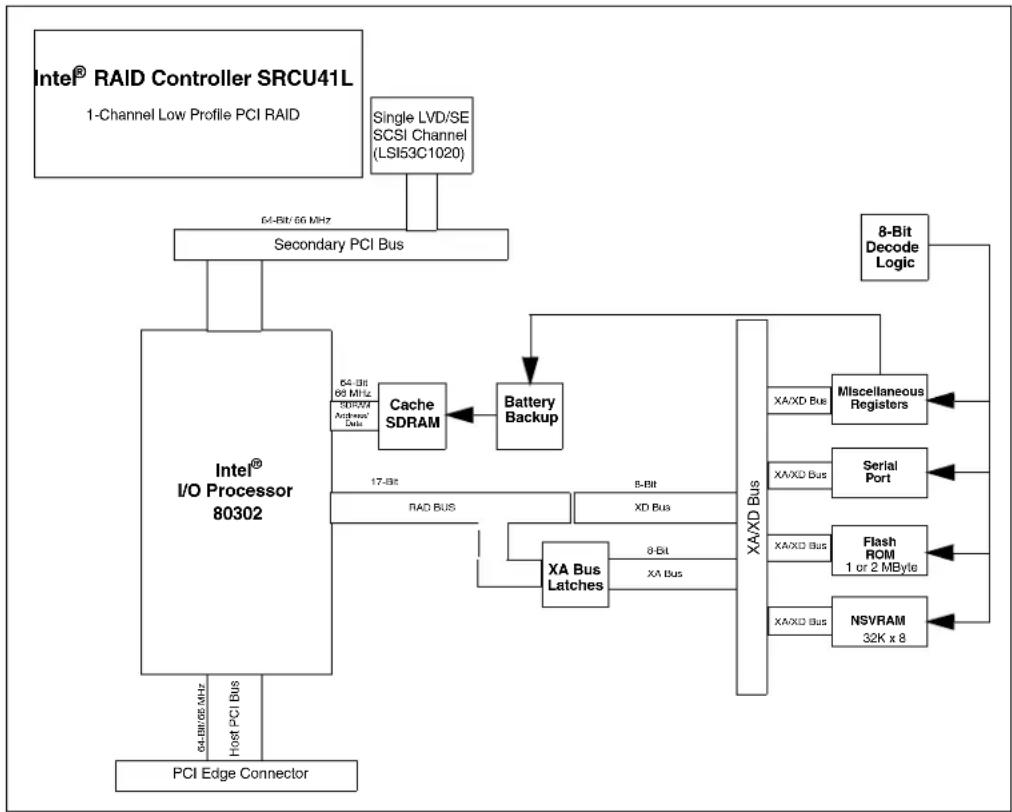
- The Intel ^ Raid Controller SRCU41L has one LSI53C1020 controller chip that controls one SCSI channel. The Intel ^ Raid Controller SRCU41L has one very high-density cable interconnect (VHDCI) 68-pin external SCSI connector and one high-density cable interconnect (HDCI) 68-pin internal SCSI connector.
Figure 1. Intel® Raid Controller SRCU41L Block Diagram
flowchart
graph TD
    A["Intel® RAID Controller SRCU41L<br>1-Channel Low Profile PCI RAID"] --> B["Single LVD/SE<br>SCSI Channel<br>(LSI53C1020)"]
    B --> C["Secondary PCI Bus"]
    C --> D["PCI Edge Connector"]
    D --> E["PCI / 64-bit/66 MHz"]
    E --> F["I/O Processor 80302"]
    F --> G["Cache SDRAM"]
    G --> H["Battery Backup"]
    H --> I["XA Bus Latches"]
    I --> J["8-Bit"]
    I --> K["XA Bus"]
    J --> L["8-Bit"]
    K --> M["XA/XD Bus"]
    L --> N["Miscellaneous Registers"]
    M --> O["Serial Port"]
    N --> P["Flash ROM<br>1 or 2 MByte"]
    O --> Q["NSVRAM<br>32K x 8"]
    P --> R["8-Bit Decode Logic"]
    Q --> R
    F --> S["64-bit/66 MHz<br>Host PCI Bus"]
    F --> T["64-bit<br>66 MHz<br>Antenna/Date"]
    F --> U["17-bit<br>RAD BUS"]
    F --> V["8-Bit<br>XD Bus"]
    F --> W["8-Bit<br>XA Bus"]
The Intel ^® Raid Controller SRCU41L supports a low-voltage differential (LVD) or a single-ended (SE) SCSI bus. With LVD, you can use cables up to 12 meters long. Throughput on each SCSI channel can be as high as 320 Mbps.
PCI is an I/O architectures. It is designed to increase data transfers without slowing down the central processing unit (CPU). You can install the Intel ^® SRCU41L Raid Controller storage adapter in PCI computer systems with a standard bracket type. With these adapters in your system, you can connect SCSI devices over a SCSI bus.
Note: For Ultra320 SCSI performance, you must connect only LVD devices to the bus. Do not mix SE with LVD devices, or the bus speed will be limited to the slower SE (Ultra SCSI) SCSI data transfer rates. Do not connect a high voltage differential (HVD) device to the controller.
1.1.1 Operating System Support
The Intel ^® Raid Controller SRCU41L supports major operating systems, such as Windows (2000, Server 2003, and XP), Red Hat* Linux, SuSe Linux, Novell* NetWare, SCO* OpenServer, and UnixWare*. Other software support ensures data integrity by intelligently testing the network before completing negotiation.
1.2 Features
Features of the Intel ^® Raid Controller SRCU41L include:
- support for hard drives with capacities greater than eight Gbytes
• online RAID level migration - RAID remapping
• no reboot necessary after expansion
• Intel I/O Processor 80302 @ 66 MHz PCI 64/66
• more than 200 Qtags per array - user-specified rebuild rate
- Wide Ultra320 LVD SCSI performance up to 320 Mbps
- 64 Mbytes of synchronous dynamic random access memory (SDRAM) integrated on the board for the Intel® SRCU41L Raid Controller.
- one internal and one external SCSI connector for the Intel® Raid Controller SRCU41L
• support for RAID levels 0, 1, 5, 10, and 50 - advanced array configuration and management utilities
• online capacity expansion and raid configuration simple and full featured BIOS tool - support for up to 14 SCSI drives per channel on storage system with SAF-TE enclosures (SCSI accessed fault-tolerant enclosures): 15 SCSI drives per channel for other configurations
- 32 Kbits x 8 NVRAM for storing RAID system configuration information; the Intel ^ Raid Controller SRCU41L firmware is stored in flash ROM for easy upgrade.
Note: Battery backup is available for the Intel ^ SRCU41L Raid Controller through a daughter card. You can purchase the controller with the battery backup unit (BBU) or purchase the BBU separately.
1.2.1 Drive Roaming
Drive roaming (also known as configuration on disk) is when the hard drives are moved around in a given configuration. Configuration information is saved in both nonvolatile random access memory (NVRAM) on the Intel ^® SRCU41L Raid Controller and in the hard drives attached to the controller. This maintains the integrity of the data on each drive, even if the drives have changed their target ID.
Before performing drive roaming, make sure that you have first powered off both your platform and your drive enclosure.
1.2.2 Drive Migration
Drive migration is the transfer of a set of hard drives in an existing configuration from one controller to another. This is always done on a blank controller. Drives should not be roamed and migrated at the same time.
1.3 Hardware
You can install the Intel ^® SRCU41L Raid Controller in a computer with a mainboard that has 5 V or 3.3 V, 32- or 64-bit PCI slots.
The following subsection describes the hardware configuration feature.
1.3.1 Intel ^® SRCU41L Raid Controller Features
Table 1. Intel ^ Raid Controller SRCU41L Storage Adapter Comparisons
| Specification Intel | ^ SRCU41L Raid Controller |
| RAID Levels 0, 1, 5, 10, 50 | |
| SCSI Device Types Synchronous or Asynchronous | |
| Devices per SCSI Channel Up to 15 Wide SCSI devices | |
| SCSI Channels 1 | |
| SCSI Data Transfer Rate Up to 320 Mbytes/s per channel | |
| SCSI Bus LVD or SE | |
| Cache Function | Write-back, Write-through, Adaptive Read Ahead, Non Read Ahead, Read Ahead, Cache I/O, Direct I/O |
| Multiple Logical Drives/Arrays per Controller | Up to 40 logical drives per controller or per logical array |
| Maximum # of Intel ^ Raid Controller SRCU41Ls per System | 12 |
| Online Capacity Expansion | Yes |
| Dedicated and Pool Hot Spare | Yes |
| Hot Swap Devices Supported | Yes |
| Non-Disk Devices Supported | Yes |
| Mixed Capacity Hard Disk Drives | Yes |
| Number of 16-bit Internal Connectors | 1 |
| Number of 16-bit External Connectors | 1 |
| Cluster Support | No |
| Hardware Exclusive OR (XOR) Assistance | Yes |
| Direct I/O | Yes |
| Architecture | Fusion-MPT |
This chapter describes the procedures used to install the Intel ^® Raid Controller SRCU41L. It contains the following sections:
• Section 2.1, “Requirements” on page 5
• Section 2.2, “Quick Installation” on page 5
• Section 2.3, “Detailed Installation” on page 6
• Section 2.4, “After You Have Installed the Storage Adapter” on page 11
2.1 Requirements
The following items are required to install a Intel ^® Raid Controller SRCU41L:
• An Intel ^® SRCU41L Raid Controller
- A host computer with an available 32-bit or 64-bit PCI expansion slot
- The Resource CD, which contains drivers and documentation
- The necessary internal and/or external SCSI cables
- Ultra, Ultra2, Ultra160, or Ultra320 SCSI hard disk drives (although backward compatible, SCSI uses the speed of the slowest device on the bus)
Intel strongly recommends using an uninterruptible power supply (UPS).
2.2 Quick Installation
The following steps are for quick Intel ^® Raid Controller SRCU41L installation. These steps are for experienced computer users/installers. Section 2.3, “Detailed Installation”, contains the steps for all others to follow.
- Turn power off to the server and all hard disk drives, enclosures, and system components and remove the PC power cord.
- Open the cabinet of the host system by following the instructions in the host system technical documentation.
- Determine the SCSI ID and SCSI termination requirements.
- Install the Intel ^ Raid Controller SRCU41L in the server, connect SCSI devices to it, and set termination correctly on the SCSI channel(s). Ensure that the SCSI cables you use conform to all SCSI specifications.
- Perform a safety check.
— Ensure that all cables are properly attached.
— Ensure that the Intel ^® Raid Controller SRCU41L is properly installed.
— Close the cabinet of the host system.
- Turn power on after completing the safety check.
2.3 Detailed Installation
This section provides detailed instructions for installing a Intel ^® Raid Controller SRCU41L.
- Unpack the Storage Adapter
Unpack and remove the Intel ^® Raid Controller SRCU41L. Inspect it for damage. If it appears damaged, or if any items listed below are missing, contact your Intel support representative.
The Intel ^® Raid Controller SRCU41L is shipped with
— the Intel ^® SRCU41L Raid Controller CD, which contains drivers for supported operating systems, an electronic version of this Hardware and Software User Guide, and other related documentation.
— a license agreement
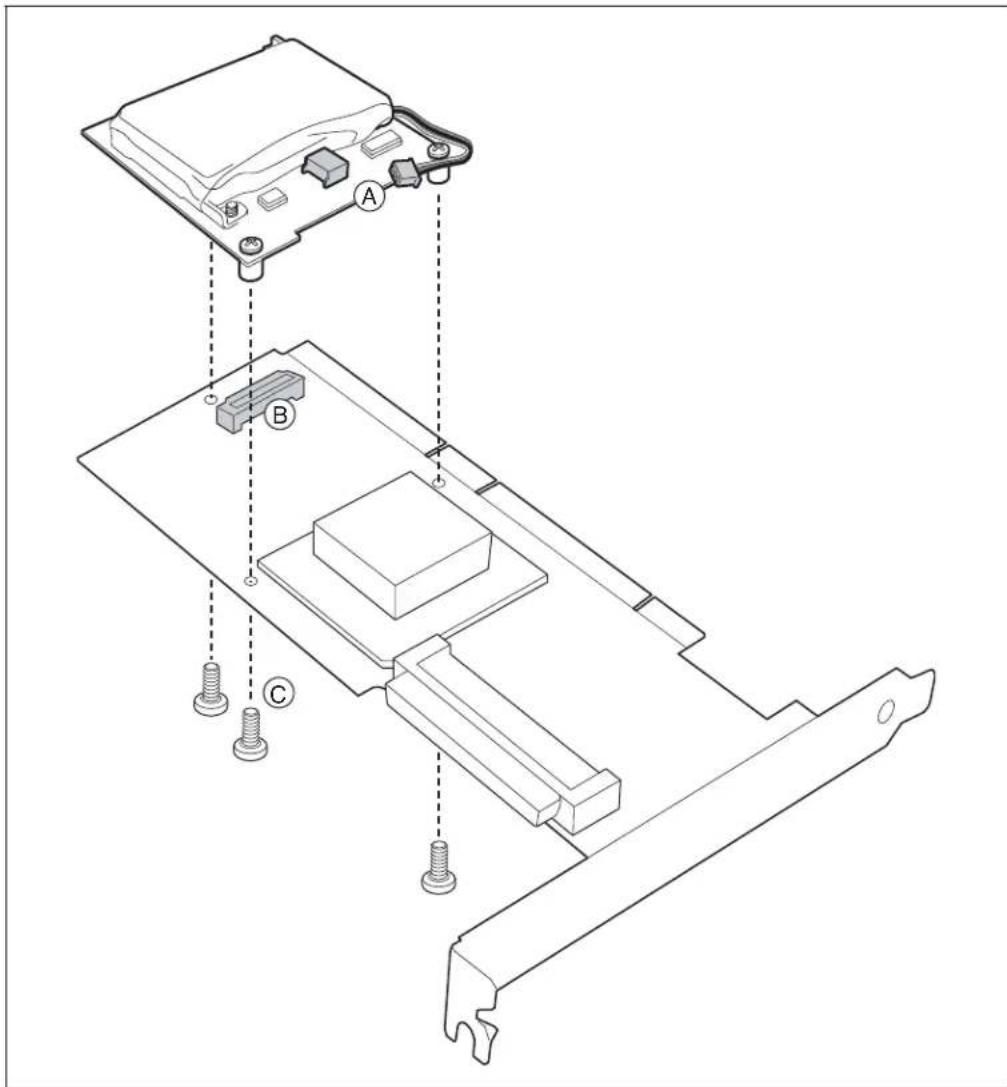
- (Optional, required to enable Write Back Cache) Attach Battery Backup Unit (BBU) to the adapter.
a. Remove the Battery Backup Unit from its packaging.
b. Connect the wire from the battery to the circuit board. (A)
c. Position the BBU over the RAID adapter so the connectors line up (B). Press the BBU onto the adapter.
d. Turn the adapter over.
e. Using three screws (C), secure the BBU to the RAID adapter.
Figure 2. Install the Battery Backup Unit
- Power Down the System
Turn off the computer and remove the AC power cord. Remove the system's cover. See the system documentation for instructions.
- Check the jumpers.
Ensure that the jumper settings on the your Intel ^® Raid Controller SRCU41L are correct. See Chapter 3, “Storage Adapter Characteristics” for diagrams of the Intel ^® Raid Controller SRCU41Ls with their jumpers and connectors.
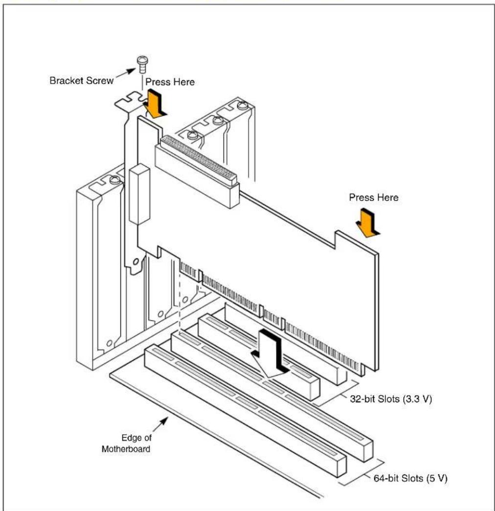
- Install the Intel ^® SRCU41L Raid Controller
Select a PCI slot and align the Intel ^® Raid Controller SRCU41L PCI bus connector to the slot. Press down gently but firmly to ensure that the card is properly seated in the slot, as shown in Figure 3. Then screw the bracket into the computer chassis.
Figure 3. Inserting the Intel® SRCU41L Raid Controller in a PCI Slot
6. Set the Target IDs.
Set target identifiers (TIDs) on the SCSI devices. Each device in a channel must have a unique TID. Provide unique TIDs for non-disk devices (CD-ROM or tapes), regardless of the channel where they are connected. The Intel ^® Raid Controller SRCU41L automatically occupies TID 7, which is the highest priority. The arbitration priority for a SCSI device depends on its TID.
Table 2. Target IDs
| Priority Highest Lowest | |||||||||||
| TID 7 6 5 . . . 2 1 0 | 15 14 | . . . 9 8 | |||||||||
7. Connect SCSI Devices to the Storage Adapter
Use SCSI cables to connect SCSI devices to the Intel ^® Raid Controller SRCU41L.
To connect the SCSI devices
a. Disable termination on any SCSI device that does not sit at the end of the SCSI bus.
b. Configure all SCSI devices to supply TERMPWR.
c. Connect cables to the SCSI devices. See the following table for maximum cable lengths.
| Device Cable Length in Meters | |
| Fast SCSI (10 Mbytes/s) 3 | |
| SE SCSI 3 | |
| Ultra SCSI 1.5 | |
| LVD 12 | |
You can connect up to 15 Ultra SCSI devices to each SCSI channel.
System throughput problems can occur if SCSI cables are not the correct type. To minimize the potential for problems,
— use cables no longer than 12 meters for Ultra160 and Ultra320 devices (it's better to use shorter cables if possible)
— use the shortest SCSI cables for SE SCSI devices (no longer than 3 meters for Fast SCSI, no longer than 1.5 meters for an 8-drive Ultra SCSI system, and no longer than 3 meters for a 6-drive Ultra SCSI system)
— use active termination
— avoid clustering the cable nodes
— note that the cable stub length must be no greater than 0.1 meter (4 inches)
— use high impedance cables
— route SCSI cables carefully.
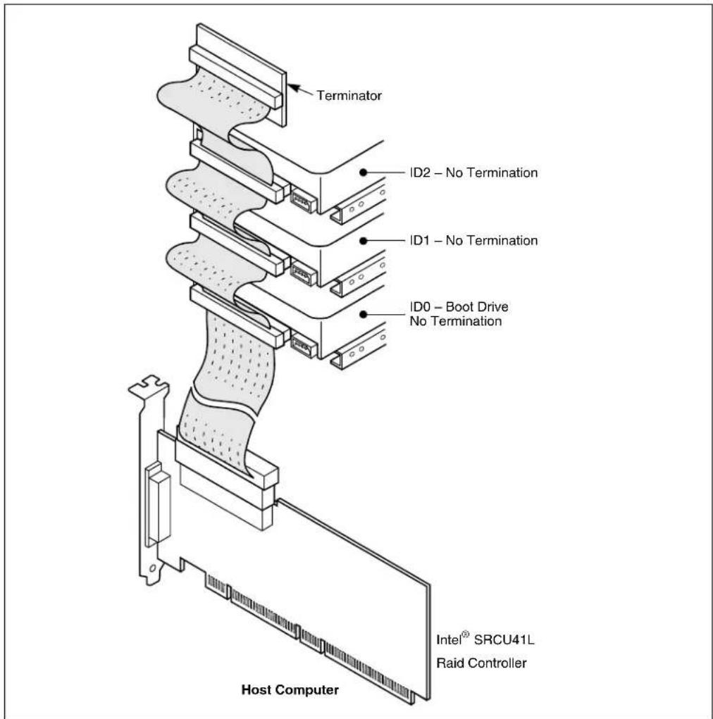
8. Set SCSI Termination
The SCSI bus is an electrical transmission line and must be terminated properly to minimize reflections and losses. Set termination at each end of the SCSI cable(s).
For a disk array, set SCSI bus termination so that removing or adding a SCSI device does not disturb termination. An easy way to do this is to connect the Intel ^ Raid Controller SRCU41L to one end of the SCSI cable and to connect an external terminator module at the other end of the cable. You can then connect SCSI disk drives to the connectors between the two ends of the cable. If necessary, disable termination on the SCSI devices. (This is not necessary for Ultra320 and Ultra160 SCSI drives.)
Set the termination so that SCSI termination and TermPWR are intact when any disk drive is removed from a SCSI channel, as shown in Figure 4.
Figure 4. Terminating an Internal SCSI Disk Array
9. Power On Host System
Replace the computer cover, and reconnect the AC power cords. Turn power on to the host computer. Ensure that the SCSI devices are powered up at the same time as, or before, the host computer. If the computer is powered up before a SCSI device, the device might not be recognized.
During boot, a BIOS message appears.
The firmware takes several seconds to initialize. During this time, the Intel ^® Raid Controller SRCU41L scans the SCSI channel(s).
The Intel ^® Raid Controller SRCU41L BIOS Configuration utility prompt times out after several seconds. The second portion of the BIOS message displays the Intel ^® Raid Controller SRCU41L number, firmware version, and cache SDRAM size. The numbering of the controllers follows the PCI slot scanning order used by the host mainboard.
If you want to run the Intel ^® Raid Controller SRCU41L Configuration utility or BIOS Console at this point, press the appropriate keys when this message appears:
Press
2.3.1 Resolving a Configuration Mismatch
If the replacement controller has a previous configuration, a message displays during the power-on self test (POST) stating that there is a configuration mismatch. A configuration mismatch occurs when the configuration data in the NVRAM and the hard disk drives are different. You need to update the configuration data in the NVRAM with the data from the hard disk drive.
Perform the following steps to resolve the mismatch.
- Press
when prompted during bootup to access the BIOS Configuration Utility. - Select Configure—> View/Add Configuration.
This gives you the option to view both the configuration on the NVRAM and the hard drive disk. - Select the configuration on disk.
- Press
and select YES to update NVRAM. - Exit and reboot.
2.4 After You Have Installed the Storage Adapter
After Intel ^® Raid Controller SRCU41L installation, you must configure the Intel ^® Raid Controller SRCU41L and install the operating system driver. The Software User's Guide instructs you on the configuration options and how to set them on your Intel ^® Raid Controller SRCU41L. The Software User's Guide also provides detailed installation instructions for operating system drivers.
Hardware Installation
intel®
This chapter describes the characteristics of the Intel ^® Raid Controller SRCU41L. This chapter contains the following sections:
- “The Intel ^ Raid Controller SRCU41L Storage Adapter Overview”
- “Intel ^ Raid Controller SRCU41L Characteristics”
- “Technical Specifications”
3.1 The Intel ^® Raid Controller SRCU41L Storage Adapter Overview
PCI is a high-speed standard local bus for interfacing I/O components to the processor and memory subsystems in a high-end PC. The component height on the top and bottom of the Ultra320 SCSI host adapters follows the PCI Local Bus Specification, Revision 2.2, and PCI-X Addendum to the PCI Local Bus Specification, Revision 1.0a. The Intel ^® Raid Controller SRCU41Ls are used in PCI systems with PCI standard and bracket type.
Table 5 on page 16 lists the features for the Intel ^® Raid Controller SRCU41L.
3.1.1 Single-Channel Raid Controller
The Intel ^® SRCU41L Raid Controller is a single-channel Ultra320 SCSI-to-PCI storage adapter that supports one Ultra320 SCSI channel. The Intel ^® Raid Controller SRCU41L SCSI channel interface is made through connectors J1 and J7. See Figure 5 and Table 3 for information about the important connectors and headers on the Intel ^® SRCU41L Raid Controller.
Figure 5. Intel ^® Raid Controller SRCU41L Card Layout
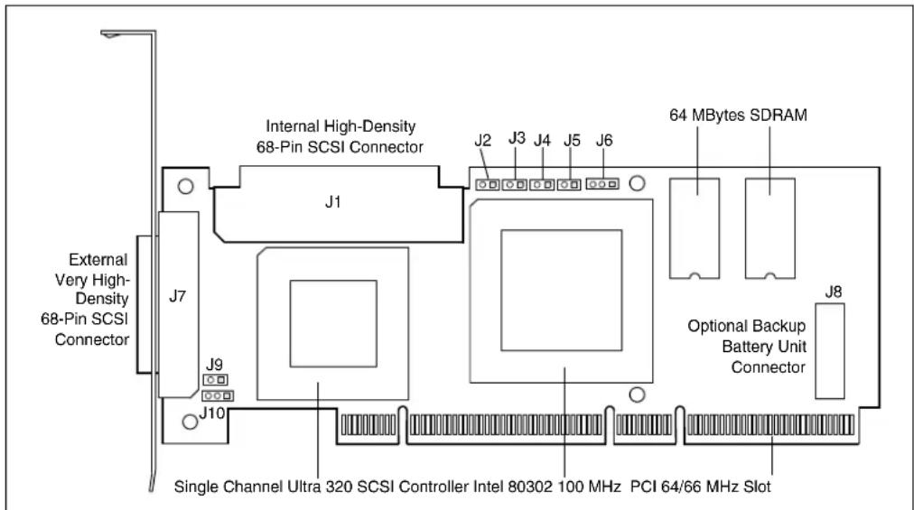
Table 3. Intel ^ Raid Controller SRCU41L Headers and Connectors
| Connector | Description Type | Comments | |
| J1 | Internal SCSI Connector | 68-pin connector | Internal high-density SCSI bus connector. |
| J2 Dirty | Cache LED 2-pin header | Connector for an LED mounted on the system enclosure. The LED is lit when the data in the cache has not yet been written to the storage device. | |
| J3 Clear | EPROM 2-pin header | Deletes the configuration data in the erasable programmable read-only (EPROM) memory. | |
| J4 | Onboard BIOS Enable | 2-pin header | No jumper: RAID onboard BIOS enabled (default)Jumpered: RAID onboard BIOS disabled |
| J5 SCSI | Activity LED 2-pin header | Connector for enclosure LED to indicate data transfers.Connection is optional. | |
| J6 | I^2C Header | 3-pin connector | Reserved |
| J7 | External SCSI Connector | 68-pin connector | External very high-density SCSI bus connector |
| J8 | BBU Daughter Card Connector | 40-pin connector | Connector for optional backup battery unit (BBU)located on a daughter card |
| J9 | Termination Power Enable | 2-pin header | Jumpered: Onboard termination power enabled. (default - do not change) |
| J10 | SCSI Bus Termination Enable | 3-pin header | Jumper on pins 1-2: Software uses drive detection to control SCSI termination (default: do not change).Jumper on pins 2-3: Onboard SCSI termination disabled.No jumper: Onboard SCSI termination enabled. |
NOTE: The Intel ^® SRCU41L Raid Controller does not have an alarm integrated onto the board. For an alarm, the controller requires a daughter card with integrated alarm. If you order the daughter card for battery backup, it will have the alarm on it.
3.1.2 Decoding the Audible Alarm
The following beep codes are used on Intel RAID controllers that use software stack 2. Thesecodes usually indicate a drive has failed:
- Degraded Array: Short tone, one second on, one second off
- Failed Array: Long tone, three seconds on, one second off
- Hot Spare Commissioned: Short tone, one second on, three seconds off
These drive failure tones will repeat until the problem is corrected or until the alarm issilenced or disabled.
A tone alarm will also sound and will remain on during a rebuild. After the rebuild completes, an alarm with a different tone will sound, signaling the completion of the build. This is a onetime (non-repeating) tone.
The alarm can be disabled either in the BIOS Console or in the Web Console management utilities. When disabled, the alarm will not sound unless it is re-enabled in one of the utilities.
The alarm can be silenced either in the BIOS Console or in the Web Console management utilities. The default setting is enabled.
3.2 Intel ^® Raid Controller SRCU41L Characteristics
Table 4 shows the general characteristics for the Intel ^ Raid Controller SRCU41L.
Table 4. Intel ^ Raid Controller SRCU41L Characteristics
| Flash ROMa | Serial EEPROMb | LVD/SE Signaling | Ultra320 SCSI Data Transfers SCSI Features | SCSI Termination |
| Yes Yes | 16-bit SE or LVD interfaces | Up to 320 Mbytes/s as well as Fast, Ultra, Ultra2, and Ultra160 speeds; Synchronous offsets up to 62. | Plug n Play Scatter/Gather Activity LED |
a. For boot code and firmware
b. For BIOS configuration storage
The Intel ^® Raid Controller SRCU41L ensures data integrity by intelligently validating the compatibility of the SCSI domain. The Intel ^® SRCU41L Raid Controller also uses Fusion-MPT architecture that allows for thinner drivers and better performance.
3.3 Technical Specifications
The design and implementation of the Intel ^® Raid Controller SRCU41L minimizes electromagnetic emissions, susceptibility to radio frequency energy, and the effects of electrostatic discharge. The Intel ^® SRCU41L Raid Controller carries the CE mark, C-Tick mark, FCC Self-Certification logo, Canadian Compliance Statement, Korean MIC, Taiwan BSMI, and Japan VCCI, and they meet the requirements of CISPR Class B.
3.3.1 Specifications
Table 5 lists the specifications for the Intel ^ SRCU41L Raid Controller.
Table 5. Intel ^® Raid Controller SRCU41L Specifications
| Specification Intel | ®Raid Controller SRCU41L |
| Processor (PCI Controller) | Intel®8030264-bit RISC processor @ 66 MHz |
| Operating Voltage 3.3 V, 5 V, +12 V with battery | only |
| Card Size | Low-Profile, Half-length PCI Adapter card size (6.875" X 4.2") |
| Array Interface to Host PCI Rev 2.2 | |
| PCI Bus Data Transfer Rate | Up to 533 Mbytes/s at 64-bit/66 MHz |
| SCSI Controller(s) One LSI53C1020 Single SCSI controller | |
| SCSI Connectors | One 68-pin internal high-density connector for SCSI devices. One very high-density 68-pin external connector for Ultra320 and Wide SCSI. |
| SCSI Bus Termination Active, single-ended or LVD | |
| Termination Disable Automatic through cable and device detection | |
| Cache Configuration | Integrated 64 Mbytes 66 MHz ECC |
| Double-Sided Dual Inline Memory Modules (DIMMs) | No |
| Size of Flash ROM for Firmware | 1 Mbyte flash ROM |
| Non-volatile Random Access Memory (NVRAM) | 32 Kbyte for storing RAID configuration |
3.3.2 Array Performance Features
Table 6 shows the Intel ^® Raid Controller SRCU41L array performance features.
Table 6. Array Performance Features
| Specification Intel | ®Raid Controller SRCU41L |
| PCI Host Data Transfer Rate | 533 Mbytes/s |
| Drive Data Transfer Rate | 320 Mbytes/s |
| Maximum Scatter/Gathers | 26 elements |
| Maximum Size of I/O Requests | 6.4 Mbytes in 64 Kbyte stripes |
| Maximum Queue Tags per Drive | As many as the drive can accept |
| Stripe Sizes | 2, 4, 8, 16, 32, 64, or 128 Kbyte |
| Maximum Number of Concurrent Commands | 255 |
| Support for Multiple Initiators | Yes |
3.3.3 Fault Tolerance
Table 7 shows the Intel ^ Raid Controller SRCU41L fault tolerance features.
Table 7. Intel ^ Raid Controller SRCU41L Fault Tolerance Features
| Specification Intel | ®Raid Controller SRCU41L |
| Support for SMARTa | Yes |
| Optional Battery Backup for Cache Memory | 3.6 V/600mAh battery pack. Up to 48 hours data retention for 64 MB. |
| Drive Failure Detection Automatic | |
| Drive Rebuild Using Hot Spares Automatic | |
| Parity Generation and Checking Yes |
a. The Self Monitoring Analysis and Reporting Technology (SMART) detects up to 70 percent of all predictable disk drive failures. SMART also monitors the internal performance of all motors, heads, and drive electronics.
3.3.4 Electrical Characteristics
This section provides the power requirements for the Intel ^® Raid Controller SRCU41Ls. Table 8 lists the maximum power requirements, which include SCSI TERMPWR, under normal operation.
Table 8. Maximum Power Requirements
| Storage Adapter | PCI/PCI-X/Express +12 V | PCI/PCI-X +5.0 V | PCI/PCI-X/Express+3.3 V | PCI PRSNT1#/PRSNT2#Power | Over the Operating Range |
| 320-1 | 115 mA; used only if battery is present | 1.5 A (PCI only) | N/A | 15 W | 0 °C to 55 °C |
3.3.5 Thermal and Atmospheric Characteristics
For all Intel ^® Raid Controller SRCU41Ls, the thermal and atmospheric characteristics are
• relative humidity range: 5% to 90% noncondensing
• maximum dew point temperature: 32 °C
- airflow must be at least 300 lfm to keep the LSI53C1020 and LSI53C1030 heat sink temperature below 80^
The following parameters define the storage and transit environment for the Intel ^® Raid Controller SRCU41L
• temperature range: -40^ to +105^ (dry bulb)
• relative humidity range: 5% to 90% noncondensing
3.3.6 Safety Characteristics
The Intel ^® Raid Controller SRCU41L meets or exceeds the requirements of UL flammability rating 94 V0. Each bare board is also marked with the supplier's name or trademark, type, and UL flammability rating. For the boards installed in a PCI bus slot, all voltages are below the SELV 42.4 V limit.
Figure 6. Glossary of Terms and Abbreviations
| Term Definition | |
| Active Termination | The electrical connection required at each end of the SCSI bus. composed of active voltage regulation and a set of termination resistors. Ultra SCSI, Ultra2 SCSI, Ultra160 SCSI, and Ultra320 SCSI require active termination. |
| BIOS | Basic Input/Output System. Software that provides basic read/write capability. Usually kept as firmware (ROM based). The system BIOS on the mainboard of a computer is used to boot and control the system. The SCSI BIOS on your host adapter acts as an extension of the system BIOS. |
| Configuration | Refers to the way a computer is setup; the combined hardware components (computer, monitor, keyboard, and peripheral devices) that make up a computer system; or the software settings that allow the hardware components to communicate with each other. |
| Device Driver | A program that allows a microprocessor (through the operating system) to direct the operation of a peripheral device. |
| Differential SCSI | A hardware configuration for connecting SCSI devices. It uses a pair of lines for each signal transfer (as opposed to Single-Ended SCSI which references each SCSI signal to a common ground). |
| Domain Validation | Domain Validation is a software procedure in which a host queries a device to determine its ability to communicate at the negotiated Ultra320 data rate. |
| EEPROM | Electronically Erasable Programmable Read-Only Memory. A memory chip typically used to store configuration information, as it provides stable storage for long periods without electricity and can be reprogrammed. See NVRAM. |
| External SCSI Device | A SCSI device installed outside the computer cabinet. These devices are connected together using specific types of shielded cables. |
| Host | The computer system in which a storage adapter is installed. It uses the storage adapter to transfer information to and from devices attached to the SCSI bus. |
| Host Adapter Board (HAB) | A circuit board or integrated circuit that provides a device connection to the computer system. |
| Internal SCSI Device | A SCSI device installed inside the computer cabinet. These devices are connected together using an unshielded ribbon cable. |
| Main Memory | The part of a computer's memory which is directly accessible by the CPU (usually synonymous with RAM). |
| NVRAM | Non-volatile Random Access Memory. Actually an EEPROM (Electronically Erasable Read-Only Memory chip) used to store configuration information. See EEPROM. |
| PCI and PCI-X | Peripheral Component Interconnect. A high performance local bus specification that allows connection of devices directly to computer memory. The PCI Local Bus allows transparent upgrades from 32-bit data path at 33 MHz to 64-bit data path at 33 MHz, and from 32-bit data path at 66 MHz to 64-bit data path at 66 MHz. |
| Peripheral Devices | A piece of hardware (such as a video monitor, disk drive, printer, or CD-ROM) used with a computer and under the computer's control. SCSI peripherals are controlled through a SCSI Shortened Product Name (host adapter). |
| SCSI Bus | A storage adapter (host adapter) and one or more SCSI peripherals connected by cables in a linear configuration. The adapter may exist anywhere on the bus, allowing connection of both internal and external SCSI devices. A system may have more than one SCSI bus by using a multi-channel adapter or by using multiple adapters. |
Figure 6. Glossary of Terms and Abbreviations
| Term Definition | |
| SCSI Device | Any device that conforms to the SCSI standard and is attached to the SCSI bus by a SCSI cable. This includes SCSI storage adapters (host adapters) and SCSI peripherals. |
| SCSI ID | A way to uniquely identify each SCSI device on the SCSI bus. Each SCSI bus has eight available SCSI IDs numbered 0 through 7 (or 0 through 15 for Wide SCSI). The storage adapter (host adapter) usually gets the highest ID (7 or 15) giving it priority to control the bus. |
| Single-Ended SCSI | A hardware specification for connecting SCSI devices. It references each SCSI signal to a common ground. This is the most common method (as opposed to differential SCSI, which uses a separate ground for each signal). |
| TolerANT | A technology developed and used by Intel to improve data integrity, data transfer rates, and noise immunity through the use of active negation and input signal filtering. |
| Ultra SCSI | A standard for SCSI data transfers. It allows a transfer rate of up to 20 Mbytes/s over an 8-bit SCSI bus and up to 40 Mbytes/s over a 16-bit SCSI bus. |
| Ultra2 SCSI | A standard for SCSI data transfers. It allows a transfer rate of up to 40 Mbytes/s over an 8-bit SCSI bus, and up to 80 Mbytes/s over a 16-bit SCSI bus. |
| Ultra160 SCSI | A standard for SCSI data transfers. It allows a transfer rate of up to 160 Mbytes/s over a 16-bit SCSI bus. |
| Ultra320 SCSI | A standard for SCSI data transfers. It allows a transfer rate of up to 320 Mbytes/s over a 16-bit SCSI bus. |
| VHDCI | Very High-Density Cable Interconnect. This cable is used to connect external connectors to your storage adapter. |


- Intel® Raid Controller SRCU41L
- Contents
- Figures
- Tables
- Revision History
- Overview
- Operating System Support
- Features
- Drive Roaming
- Drive Migration
- Hardware
- Intel ® SRCU41L Raid Controller Features
- Requirements
- Quick Installation
- Detailed Installation
- Set the Target IDs.
- Connect SCSI Devices to the Storage Adapter
- Set SCSI Termination
- Power On Host System
- Resolving a Configuration Mismatch
- After You Have Installed the Storage Adapter
- The Intel ® Raid Controller SRCU41L Storage Adapter Overview
- Single-Channel Raid Controller
- Decoding the Audible Alarm
- Intel ® Raid Controller SRCU41L Characteristics
- Technical Specifications
- Specifications
- Array Performance Features
- Fault Tolerance
- Electrical Characteristics
- Thermal and Atmospheric Characteristics
- Safety Characteristics
Brand : INTEL
Model : SRCU41L
Category : Régulateur