
SuperTrack EX8658 - NAS Promise Technology - Free user manual and instructions
Find the device manual for free SuperTrack EX8658 Promise Technology in PDF.


| Type de produit | RAID Controller Card |
| Modèle | SuperTrack EX8658 |
| Interface | PCI-Express x8 |
| Ports SAS externes | 8 (two SFF-8088) |
| Processeur I/O | 1.2 GHz |
| Mémoire | 512 MB DDR-II |
| RAID supportés | 0, 1, 1E, 5, 6, 10, 50, 60 |
| Nombre maximal de disques | 256 (avec expandeur SAS) |
| Dimensions (HWD) | 68.3 x 168.3 x 19.0 mm (Low profile) |
| Température de fonctionnement | 0°C à 50°C (sans BBU) |
| Humidité de fonctionnement | 5% à 95% sans condensation |
| Fonctions principales | Gestion RAID via WebPAM PRO ou CLI, hot-swap, migration en ligne, expansion, S.M.A.R.T., BBU optionnel |
| Alimentation | Via le slot PCI-Express (pas d'alimentation externe) |
| Options de batterie | BBU-Plus III (optionnel) |
| Systèmes d'exploitation supportés | Windows Server 2008/2003/XP/Vista, Red Hat, openSUSE, SLES, Fedora, FreeBSD, VMware |
Frequently Asked Questions - SuperTrack EX8658 Promise Technology
User questions about SuperTrack EX8658 Promise Technology
0 question about this device. Answer the ones you know or ask your own.
Ask a new question about this device
Download the instructions for your NAS in PDF format for free! Find your manual SuperTrack EX8658 - Promise Technology and take your electronic device back in hand. On this page are published all the documents necessary for the use of your device. SuperTrack EX8658 by Promise Technology.
USER MANUAL SuperTrack EX8658 Promise Technology
Version 3.0 SR3
Copyright
© 2009 Promise Technology, Inc. All Rights Reserved.
Copyright by Promise Technology, Inc. (Promise Technology). No part of this manual may be reproduced or transmitted in any form without the expressed, written permission of Promise Technology.
Trademarks
Promise, and the Promise logo are registered in U.S. Patent and Trademark Office. All other product names mentioned herein may be trademarks or registered trademarks of their respective companies.
Important data protection information
You should back up all data before installing any drive controller or storage peripheral. Promise Technology is not responsible for any loss of data resulting from the use, disuse or misuse of this or any other Promise Technology product.
Notice
Although Promise Technology has attempted to ensure the accuracy of the content of this manual, it is possible that this document may contain technical inaccuracies, typographical, or other errors. Promise Technology assumes no liability for any error in this publication, and for damages, whether direct, indirect, incidental, consequential or otherwise, that may result from such error, including, but not limited to loss of data or profits.
Promise Technology provides this publication “as is” without warranty of any kind, either express or implied, including, but not limited to implied warranties of merchantability or fitness for a particular purpose.
The published information in the manual is subject to change without notice. Promise Technology reserves the right to make changes in the product design, layout, and driver revisions without notification to its users.
This version of the User Manual supersedes all previous versions.
Recommendations
In this Manual, the appearance of products made by other companies, including, but not limited to software, servers, and physical drives, is for the purpose of illustration and explanation only. Promise Technology does not recommend, endorse, prefer, or support any product made by another manufacturer.
Radio Frequency Interference Statement
This equipment has been tested and found to comply with the limits for a Class B digital device, pursuant to Part 15 of the FCC Rules. These limits are designed to provide reasonable protection against harmful interference in a residential installation. This equipment generates, uses and can radiate radio frequency energy, and, if not installed and used in accordance with the instruction may cause harmful interference to radio communications. However, there is no guarantee that interference will not occur in a particular installation. If this equipment does cause harmful interference to radio or television reception, which can be determined by turning the equipment off and on, the user is encouraged to try to correct the interference by one or more of the following measures:
- Reorient or relocate the receiving antenna.
- Increase the separation between the equipment and receiver.
- Connect the equipment into an outlet on a circuit different from that to which the receiver is connected.
- Consult Promise Technology, Inc. or an experienced radio or TV technician for help.
This device complies with Part 5 of the FCC Rules. Operation is subject to the following conditions: (1) This device may not cause harmful interference, and (2) this device must accept any interference received, including interference that may cause undesired operation.

Caution
Only digital device equipment CERTIFIED CLASS B should be attached to this equipment and that must have shielded cables.
Contents
Chapter 1: Introduction .....1
About This Manual ....1
Product Overview 2
XOR Microprocessor....2
Hot-Swapping 2
WebPAM PRO Management Software ....3
Operating System Support 3
Browser Support 4
Key Features and Benefits 4
Specifications 6
Chapter 2: Installation .....7
Unpacking the SuperTrak Card ....7
Installing the SuperTrak Card 9
Connecting SuperTrak to a SuperSwap Enclosure .....14
Connecting SuperTrak to a VTrak JBOD Enclosure .....14
SAS Connections and ID Numbers .....15
Choosing the Physical Drives .....17
Creating a Logical Drive 18
Installing the CLI .....23
Installing onto Windows 23
Installing onto Linux 29
Installing the CLI onto FreeBSD 36
Installing the CLI onto VMware .37
Installing WebPAM PRO 38
Utility Server 38
Agent .38
JRE 39
Internet Browser 39
Installing WebPAM PRO onto Windows 40
Installing WebPAM PRO onto Linux 49
Logging into WebPAM PRO ....58
Logging in at the Host PC .58
Logging in over the Network .....58
Login Screen....59
Setting up WebPAM PRO 60
Chapter 3: Installing Drivers ....63
Driver Installation Media 64
Windows 64
Linux and FreeBSD 65
Windows Server 2008 66
New OS Installation 66
Existing System 67
Confirming Driver Installation 67
Windows Vista....68
New OS Installation 68
Existing System 69
Confirming Driver Installation 69
Windows Server 2003 ....70
New OS Installation 70
Existing System 71
Confirming Driver Installation 71
Windows XP 72
New OS Installation 72
Existing System 73
Confirming Driver Installation 73
Red Hat Linux Enterprise 4.4, 4.5, 4.6, 4.7 .....74
New OS Installation 74
Existing System 74
Fedora Core 6 75
New OS Installation 75
Existing System 75
Fedora Core 7, 8 . . . . . . . . . . . . . . . . . . . . . . . . . . . . . . . . . . . . . . . . . . . . . . . . . . . . . . . . . . . . 76
New OS Installation 76
Existing System 76
openSUSE 10.2, 10.3, 10.5, 11 .....77
New OS Installation 77
Existing System 77
SLES 10, 10 SP1, 10 SP2....78
New OS Installation 78
Existing System 78
Miracle Linux 4 79
New OS Installation 79
Existing System 79
FreeBSD 6.1, 6.2, 6.3, 7.0 .....80
New OS Installation 80
Existing System 81
Chapter 3: Installing Drivers, cont.
VMware ESX Server 3.0.2, 3.5.0 .....82
New OS Installation 82
Existing System 82
Chapter 4: SuperBuild™ Utility .....85
SuperTrak BIOS 85
Accessing the Main Menu 88
Selecting a Controller 89
Viewing Controller Information 89
Managing Physical Drives 90
Viewing Physical Drives 90
Viewing Physical Drive Information .....90
Managing Physical Drive Problems 91
Managing Disk Arrays 92
Viewing Disk Arrays .92
Viewing Disk Array Information .....92
Creating a Disk Array .93
Changing Disk Array Settings .....94
Rebuilding a Disk Array 94
Deleting a Disk Array 94
Managing Logical Drives 95
Viewing Logical Drives .95
Viewing Logical Drive Information .....95
Creating a Logical Drive 96
Initializing a Logical Drive .97
Changing Logical Drive Settings . . . . . . . . . . . . . . . . . . . . . . . . . . . . . . . . . . . . . . . . . . . . . . . . . . . . . . . . . 98
Deleting a Logical Drive .98
Managing Spare Drives .....99
Viewing Spare Drives 99
Viewing Spare Drive Information 99
Creating a Spare Drive 99
Changing Spare Drive Settings . . . . . . . . . . . . . . . . . . . . . . . . . . . . . . . . . . . . . . . 100
Deleting a Spare Drive ....101
Viewing Background Activity 102
Managing the Event Log ....103
Viewing RAM Events 103
Viewing NVRAM Events 103
Clearing the Event Logs 104
Chapter 4: SuperBuild™ Utility, cont.
Working with Time Sync ....105
Setting the Time Zone....105
Synchronizing Time with an Embedded Site .....105
Using the Miscellaneous Menu ....106
Making the SAS Ready LED Setting .....106
Making the SGPIO Backplane Setting .....106
Working with the Buzzer .....106
Chapter 5: Management with WebPAM PRO .....109
Logging into WebPAM PRO 109
Logging in at the Host PC 109
Logging in over the Network .....110
Login Screen 111
Accessing the Interface 112
Using the Header 113
Using Tree View ....113
Using Management View 114
Choosing a Display Language .....115
Viewing the Event Frame 115
Saving the Event Frame 116
Deleting the Event Frame .....116
Viewing the Storage Network .....116
Logging out of WebPAM PRO 117
Managing Users 118
Viewing User Information ....118
Making User Settings ....118
Making Your Own User Settings ....119
Changing a User's Password .....119
Changing Your Own Password ....119
Creating a User ....120
Deleting a User 120
Working with Subsystem/Host Management .....122
Viewing Subsystem/Host Information .....122
Adding a Subsystem or Host 122
In-Band versus Out-of-Band 123
Deleting a Subsystem or Host 123
Setting User Privilege 124
Updating the Firmware on Multiple Systems .....124
Chapter 5: Management with WebPAM PRO, cont.
Managing Software Services ....126
Viewing Service Status ....126
Changing Web Server Settings .....126
Restarting the Tomcat Server .....127
Setting up Email Service....127
Setting up Extended SMTP .....128
Sending A Test Email Message .....128
Setting Event Frame Refresh Time .....128
Changing CIM Client Settings .....129
Changing CIM Server Settings 129
Managing the Host 130
Viewing Host Information ....130
Setting User Rights 130
Refreshing the WebPAM PRO Screen .....130
Managing the Subsystem ....131
Viewing Subsystem Information .....131
Clearing Statistical Data 132
Setting an Alias for the Subsystem .....132
Updating the Firmware 132
Checking Subsystem Health 133
Viewing the Runtime Event Log ....134
Saving the Runtime Event Log ....134
Clearing the Runtime Event Log ....135
Viewing the NVRAM Event Log 135
Saving the NVRAM Event Log ....136
Clearing the NVRAM Event Log ....136
Viewing Current Background Activities .....136
Making Background Activity Settings .....137
Running Background Activities .....138
Running Media Patrol 138
Running PDM 138
Viewing Scheduled Activities 139
Scheduling an Activity ....139
Deleting a Scheduled Activity .....141
Viewing System Configuration .....141
Managing the Controller ....142
Viewing Controllers Information 142
Viewing Controller Information .....142
Viewing Controller Statistics .....144
Chapter 5: Management with WebPAM PRO, cont.
Managing the Controller, cont.
Making Controller Settings ....144
Clearing an Orphan Watermark 145
Viewing Battery Information ....145
Silencing the Buzzer 146
Making Buzzer Settings 146
Testing the Buzzer ....146
Viewing Buzzer Information .....147
Managing Enclosures ....148
Viewing Enclosure Information .....148
Managing Physical Drives 149
Viewing a List of Physical Drives 149
Locating a Physical Drive .....149
Making Global Physical Drive Settings 150
Viewing Physical Drive Information .....151
Viewing Physical Drive Statistics 151
Making Physical Drive Settings .....152
Clearing Stale and PFA Conditions 152
Viewing the SMART Log ....153
Viewing Advanced SMART Log Information .....154
Saving Advanced SMART Log Information 155
Making SMART Log Settings ....155
Managing Disk Arrays ....156
Viewing Disk Arrays 156
Locating a Disk Array ....156
Creating a Disk Array 157
Creating a Disk Array – Automatic Configuration .....158
Creating a Disk Array – Express Configuration .....159
Creating a Disk Array – Advanced Configuration .....161
Deleting a Disk Array 163
Viewing Disk Array Information .....163
Making Disk Array Settings .....164
Creating a Logical Drive ....165
Deleting a Logical Drive ....166
Migrating a Disk Array ....167
Rebuilding a Disk Array 168
Running Media Patrol on a Disk Array ....169
Running PDM on a Disk Array 169
Transitioning a Disk Array ....170
Preparing a Disk Array for Transport .....171
Chapter 5: Management with WebPAM PRO, cont.
Managing Logical Drives ....172
Viewing Information for All Logical Drives .....172
Locating a Logical Drive ....173
Viewing Logical Drive Information .....173
Viewing Logical Drive Statistics 174
Changing Logical Drive Settings .....174
Initializing a Logical Drive .....175
Running Redundancy Check 176
Viewing the Logical Drive Check Table .....176
Managing Spare Drives ....178
Viewing a List of Spare Drives 178
Creating a Spare Drive .....179
Deleting Spare Drive ....180
Making Spare Drive Settings 180
Running Spare Check....181
Working with the Logical Drive Summary .....182
Viewing a List of All Logical Drives .....182
Locating a Logical Drive ....182
Viewing Individual Logical Drive Information .....183
Chapter 6: Management with the CLI .....185
Opening the CLI on Windows .....185
Opening the CLI on Linux, FreeBSD, and VMware .....186
Table of Supported Commands ....187
Notes and Conventions 189
List of Supported Commands ....190
Chapter 7: Technology Background .....227
Introduction to RAID 227
RAID 0 – Stripe .....228
RAID 1 – Mirror .....229
RAID 1E – Enhanced Mirror .....230
RAID 5 – Block Striping with Distributed Parity .....231
RAID 6 – Block and Double Parity Stripe .....232
RAID 10 - Mirror / Stripe . . . . . . . . . . . . . . . . . . . . . . . . . . . . . . . . . . . . . . . . . . . . . . . . . . . . . . . . . . . . . . . . . . . . . . . . . . . . . . 233
RAID 50 – Striped Distributed Parity .....234
RAID 60 – Striping of Double Parity .....237
Chapter 7: Technology Background, cont.
Choosing a RAID Level .240
RAID 0 ....240
RAID 1 ....240
RAID 1E 241
RAID 5 241
RAID 6 242
RAID 10 242
RAID 50 ....243
RAID 60 243
Choosing Stripe Block Size .....244
Choosing Sector Size .....244
2 TB Limitation .....245
Choosing Cache Policy 245
Read Cache Policy ....246
Write Cache Policy ....246
Capacity Coercion 246
Initialization ....247
Hot Spare Drive .....248
Partition and Format the Logical Drive .....248
RAID Level Migration 248
RAID 0 .249
RAID 1 250
RAID 1E 250
RAID 5 .251
RAID 6 .251
RAID 10 .252
RAID 50 .252
RAID 60 .253
Ranges of Disk Array Expansion .....253
Media Patrol 255
Predictive Data Migration (PDM) .....255
PDM Triggers .....255
Transition....256
Drive Failure and Automatic Rebuild .....256
Automatic Transition .....258
Manual Transition .....258
Chapter 8: Troubleshooting .....261
Problems Reported by SuperTrak....261
Buzzer....261
LEDs 261
BIOS 263
Problems Reported in WebPAM PRO .....265
Opening WebPAM PRO 265
What to Look For 265
Critical & Offline Logical Drives 267
Finding the Failed Drive in SuperBuild .....267
Finding the Failed Drive in WebPAM PRO .....268
Salvaging Physical Drives 269
Clearing Stale and PFA Conditions .....269
Rebuilding a Disk Array Automatically .270
Rebuilding a Disk Array Manually .....270
Rebuilding with WebPAM PRO .....270
Rebuilding with SuperBuild .....271
Recovering from a Blank Screen .272
Cache Battery Does Not Charge .....272
Chapter 9: Support .....273
Frequently Asked Questions 273
Pre-Installation (Speed, Device Types, Capacity, Cabling) . .273
Drive Issues 274
Installation Issues (Capacity, Booting) .....275
Post-Installation 276
Contacting Technical Support . . . . . . . . . . . . . . . . . . . . . . . . . . . . . . . . . . . . . . . . . . . . . . . . . . . . . . . . . 277
Limited Warranty 280
Disclaimer of other warranties 280
Your Responsibilities ....281
Returning the Product For Repair . . . . . . . . . . . . . . . . . . . . . . . . . . . . . . . . . . . . . . . . . . . . . . . . . 282
Appendix A: Partition and Format .....285
Appendix B: Upgrades .....289
Updating SuperTrak BIOS and Firmware . . . . . . . . . . . . . . . . . . . . . . . . . . . . . . . . . . . . . . . . . . . . . . . . . . 289
Downloading BIOS and Firmware File .....289
Updating WebPAM PRO . . . . . . . . . . . . . . . . . . . . . . . . . . . . . . . . . . . . . . . . . . . . . . . . . . . . . . . . . . 290
Downloading the WebPAM PRO Update File .....290
Installing the WebPAM PRO Update File . . . . . . . . . . . . . . . . . . . . . . . . . . . . . . . . . . . . . . . . . . . 290
Logging into WebPAM PRO .....290
Appendix C: Battery Backup Unit .....291
Installing the BBU .....292
Appendix D: LED Backplane Connections .....295
Schematic Diagrams .....295
Direct LED Display .297
Aggregate LED Display .297
Global LED Display 298
Index. 299
Chapter 1: Introduction
- About This Manual, below
• Product Overview (page 2) - WebPAM PRO Management Software (page 3)
Thank you for purchasing one of Promise Technology's SuperTrak EX4650, EX8650, EX8654, EX8658, or EX16650 SAS/SATA RAID Controller card.
About This Manual
This User Manual describes how to setup, use and maintain the SuperTrak RAID controller. It also describes how to use the Web-Based Promise Array Management—Professional (WebPAM PRO) RAID management software.
This manual includes a full table of contents, chapter task lists and numerous cross-references to help you find the specific information you are looking for.
Also included are four levels of notices:

Note
A Note provides helpful information such as hints or alternative ways of doing a task.

Important
Important calls attention to an essential step or point required to complete a task. Important items include things often missed.

Caution
A Caution informs you of possible equipment damage or loss of data and how to avoid them.

Warning
A Warning notifies you of probable equipment damage or loss of data, or the possibility of physical injury, and how to avoid them.
Product Overview
SuperTrak EX4650, EX8650, EX8654, EX8658, and EX16650 are SAS and SATA RAID Controller cards. When used with WebPAM PRO software, the SuperTrak RAID Controllers offer a feature-rich, secure and versatile enterprise-wide RAID solution. In addition, the SuperTrak EX Series supports RAID expansion. The resulting RAID environment allows users and administrators to configure, manage, and monitor everything from single logical drives on local systems to logical drive networks residing in offsite locations.
The SuperTrak EX Series RAID Controller cards support SAS hard drives as well as 1.5 Gb/s and 3.0 Gb/s SATA hard drives. At its core, the SuperTrak card provides advanced RAID management functions: creating logical drives, monitoring them, keeping them online and operating at optimum efficiency. SuperTrak can also perform many other tasks, such as:
- The SuperTrak EX4650 Controller card supports up to four SAS or SATA physical drives and RAID levels 0, 1, 1E, 5, 6, and 10. With a SAS expander you can attach up to 128 drives. This Controller also supports RAID 50 and 60 with a SAS expander.
- The SuperTrak EX8650, EX8654, EX8658, and EX16650 Controller cards you can directly attach up to 16 SAS or SATA physical drives. With a SAS expander you can attach up to 256 drives. These Controllers also support RAID levels 0, 1, 1E, 5, 6, 10, 50, and 60.
- Set up a network of SuperTrak RAID servers (all running under different RAID levels) and monitor those servers from any workstation on the network.
- Create a series of SuperTrak RAID networks at any number of offsite locations.
- Monitor and repair SuperTrak RAID logical drives using the Internet from an offsite location—all without compromising the integrity of secure servers.
XOR Microprocessor
The SuperTrak EX Series Controllers have an onboard microprocessor for XOR calculations, which off loads the parity calculation workload from the main CPU and transfers it to the controller card, boosting the performance of the entire system.
Hot-Swapping
Attached drives can be hot swapped when necessary.
WebPAM PRO Management Software
The Web-Based Promise Array Management—Professional (WebPAM PRO) software offers local and remote management and monitoring of all SuperTrak logical drives that exist anywhere on a network. Browser-based GUI provides email notification of all major events or alarms, memory cache management, drive event logging, logical drive maintenance, rebuild, and access to all components in the RAID configuration (controller, physical drives, disk arrays, logical drives, physical drives, and enclosure).
For information on using WebPAM PRO, see “Chapter 5: Management with WebPAM PRO” on page 109.
Operating System Support
On the Host PC where you install the SuperTrak controller and WebPAM PRO, Promise Technology recommends:
- Windows Server 2008 (64 bit) with or without Hyper-V
• Windows Server 2008 (32 bit) - Windows Vista (32 or 64 bit)
- Windows Server 2003 SP1, SP2; R2 (32 or 64 bit)
- Windows XP Professional SP2, SP3 (32 or 64 bit)
• Red Hat Enterprise Linux 4.4, 4.5, 4.6, 4.7, 5.0, 5.1, 5.2 (32 or 64 bit) - openSUSE 10.2, 10.3, 11 (32 or 64 bit)
• SLES 10, 10 SP1, 10 SP2 (32 or 64 bit) - Miracle Linux 4 SP2, 5 (32 or 64 bit)
• Fedora Core 6, 7, 8, 9 (32 or 64 bit) - Open Source Driver for Linux 2.6 kernel (32 or 64 bit)
SuperTrak management on the following OS is supported only via CLI:
• FreeBSD 6.1, 6.2, 6.3, 7.0 (32 or 64 bit)
SuperTrak management on the following virtualization platform is supported only via CLI:
- VMware ESX 3.0.2, 3.5 (certification pending)
Browser Support
On the Host PC where you install the SuperTrak controller and WebPAM PRO, you must have one of the following browsers:
- Internet Explorer
• Fire fox - Netscape Navigator
If you do not have one of the above browsers, install the browser first and make it the default browser. Then install WebPAM PRO.
Key Features and Benefits
The following information offers an overview of the major features of the Promise SuperTrak EX4650, EX8650, EX8654, EX8658, and EX16650.
| Advanced Design | |
| Features Benefits | |
| Supports PCIe x8 bus motherboards | Allows maximum data transfers of up to 2 GB/s in both directions simultaneously to dramatically reduce the time to save and retrieve large files. |
| EX4650 supports: RAID 0, 1, 1E, 5, 6, and 10. RAID 50 and 60 with SAS Expander. | Provides dramatic increase in drive performance and/or fault tolerant options. Offers performance customization and data rebuilds from the BIOS menu. |
| EX8650, EX8654, EX8658, and EX16650 support: RAID 0, 1, 1E, 5, 6, 10, 50, and 60 | |
| Supports Serial ATA Specification II | Burst data transfer rates up to 300 MB/s from Serial ATA drives to boost overall system performance. |
| Supports Serial Attached SCSI Specification | Burst data transfer rates up to 300 MB/s from SAS drives to boost overall system performance. |
| Independent data channels for SATA and SAS drives | Drives can multiply their data transfer performance when striped together and each drive uses a separate data channel. |
| Supports multiple logical drives on the same physical drives | Up to 32 logical drives per array, Up to 128 arrays drives per controller, Up to 256 physical drives per controller, Up to 256 logical drives per controller. |
| Supports online logical drive expansion | Add disk drives to the array without affecting data availability. |
| Supports online logical drive migration | Change RAID level without affecting data availability. |
| Utilizes SuperBuildTM automenu from the SuperTrak onboard BIOS | Has “Auto Setup” option for quick and easy logical drive builds. |
| Displays status and error checking messages during bootup | Notifies user of possible errors and allows for recovery of mirrored drive logical drives directly from SuperBuildTM. |
| Supports S.M.A.R.T. monitoring and reporting | Polls status at set intervals, reports through WebPAM PRO. |
| Employs the latest Promise PCI Express SATA/SAS ASIC technology | Fully supports Serial ATA specifications with 150 and 300 MB/sec timing and CRC error-checking at high speeds. |
| Automatic background rebuilds | Fault tolerance can be restored automatically without rebooting. |
| DOS based flash upgrade of BIOS and Firmware | Verifies proper file, option to backup existing file. Download files from Promise website. |
| Capacity coercion Supports four schemes of capacity coercion. | |
| System reboot not required after create, delete, migrate or expand logical drive | System boot process continues without restarting. |
| Compatibility | |
| Features Benefits | |
| Complies with PCI Express Specification 1.0a | Provides highest level of hardware compatibility |
| Complies with SATA Specification 1.0a | Provides full compatibility with first generation SATA hard drives. |
| Complies with SATA II: Extensions to SATA 1.0a Specification | Provides enclosure and drive monitoring compatibility. |
| Complies with SAS Specification 1.1 | Provides full compatibility with SAS hard drives. |
| Tested compatibility to coexist with motherboards that have integrated IDE controllers | Improves system performance and minimizes system conflicts for new and existing installations. |
| Features LBA support Supports | drives greater than 137 GB capacity. |
| Supports BIOS Boot Specification | All logical drives attached to the SuperTrak card appear in the BBS-compliant motherboards BIOS boot list. |
Specifications
- Port Counts and Connectors
EX4650: 4 internal, one SFF-8087
EX8650: 8 internal, two SFF-8087
EX8654: 4 internal, one SFF-8087; 4 external, one SFF-8088
EX8658: 8 external, two SFF-8088
EX16650: 16 internal, four SFF-8087
- Interface: PCI-Express x8 Slot
• I / O P r o c e s s o r
EX4650: 667 MHz
EX8650: 800 MHz
EX8654, EX8658, EX16650: 1.2 GHz
- Memory (DDR-II)
EX4650: 128 MB
EX8650: 256 MB
EX8654, EX8658, EX16650: 512 MB
- Controller card dimensions (HWD):
EX4650, EX8650, EX8654, EX8658:
2.69 x 6.63 x 0.75 inches (68.3 x 168.3 x 19.0 mm) "Low profile"
EX16650:
4.37 x 6.63 x 0.75 inches (111.0 x 168.3 x 19.0 mm) "Full height"
- Operating temperatures
Without BBU: 32° to 122°F (0°C to 50°C)
With BBU: 32° to 104°F (0°C to 40°C)
- Operating humidity: 5% to 95% non-condensing
Chapter 2: Installation
- Unpacking the SuperTrak, below
- Installing the SuperTrak Card (page 9)
- Choosing the Physical Drives (page 17)
- Creating a Logical Drive (page 18)
- Installing the CLI (page 23)
- Windows (page 23)
- Linux (page 29)
- Free BSD (page 36)
-
VMware (page 37)
-
Installing WebPAM PRO (page 38)
- Windows (page 40)
-
Linux (page 49)
-
Logging into WebPAM PRO (page 58)
- Setting up WebPAM PRO (page 60)
Unpacking the SuperTrak Card
When you receive the SuperTrak EX Series SAS/SATA RAID Controller card, the package should contain the items listed below:
- SuperTrak EX4650, EX8650, EX8654, EX8658, or EX16650 Controller card
- Quick Start Guide
- 0.5m (19-inch) SFF-8087 to SFF-8087 multi-lane cable
One (1) for EX4650 and EX8654
Two (2) for EX8650
Four (4) for EX16650
- CD with WebPAM PRO software, Windows and Linux drivers, and SuperTrak User Manual
If any of the items are missing or appear damaged, please contact your dealer or distributor immediately.

Warning
The electronic components on the SuperTrak EX Controller cards are sensitive to damage from Electro-Static Discharge (ESD). Observe appropriate precautions at all times when handling the SuperTrak card or its subassemblies.

Warning
Before installing the SuperTrak EX Controller card into an existing system, backup any important or useful data. Failure to follow this accepted PC practice could result in data loss.

Important
Promise does not recommend multi-lane and fanout cables longer than 1m (38 inches) because they have not been tested with the SuperTrak controller.

Important
If your SuperTrak EX16650 card has a battery backup unit (BBU), follow these requirements to be sure the battery charges properly:
- Ambient operating temperature must not exceed 104 °F (40°C)
• Airflow through your PC or server must be at least 200 LFM

Note
The SuperTrak EX Controller cards are PCI Plug-n-Play (PnP) devices. No changes are necessary in the motherboard CMOS or BIOS Setup for resources or drive types in most applications.
Installing the SuperTrak Card
The SuperTrak EX Controller card fits into any available PCI-Express x8 slot. You can also plug the SuperTrak card into a PCI-Express x16 slot.
- Remove the cover of your system.
- Remove the inside slot cover of an available PCI-Express slot on the motherboard.
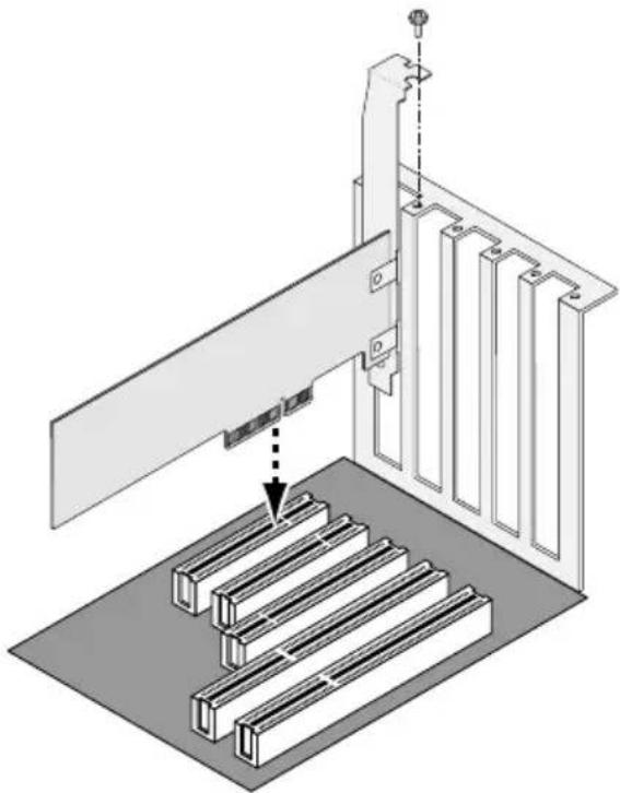
- Install the SuperTrak card into the open PCI-Express slot.
- Fasten the SuperTrak card bracket to the system case.
- Attach one end of a SAS multi-lane cable to a SAS port on the SuperTrak card.
External SAS multi-lane cables are user-supplied. The external SAS ports have SFF-8088 connectors.
See Figures 1 through 5.
Figure 1. SuperTrak EX4650 card
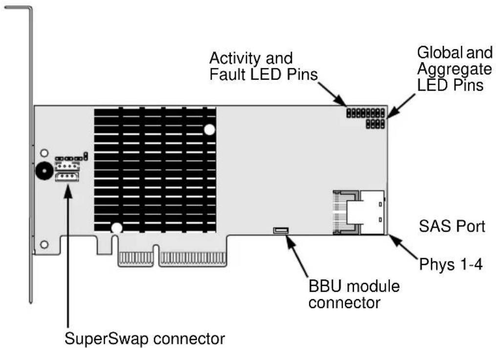
Figure 2. SuperTrak EX8650 card

Figure 3. SuperTrak EX8654 card
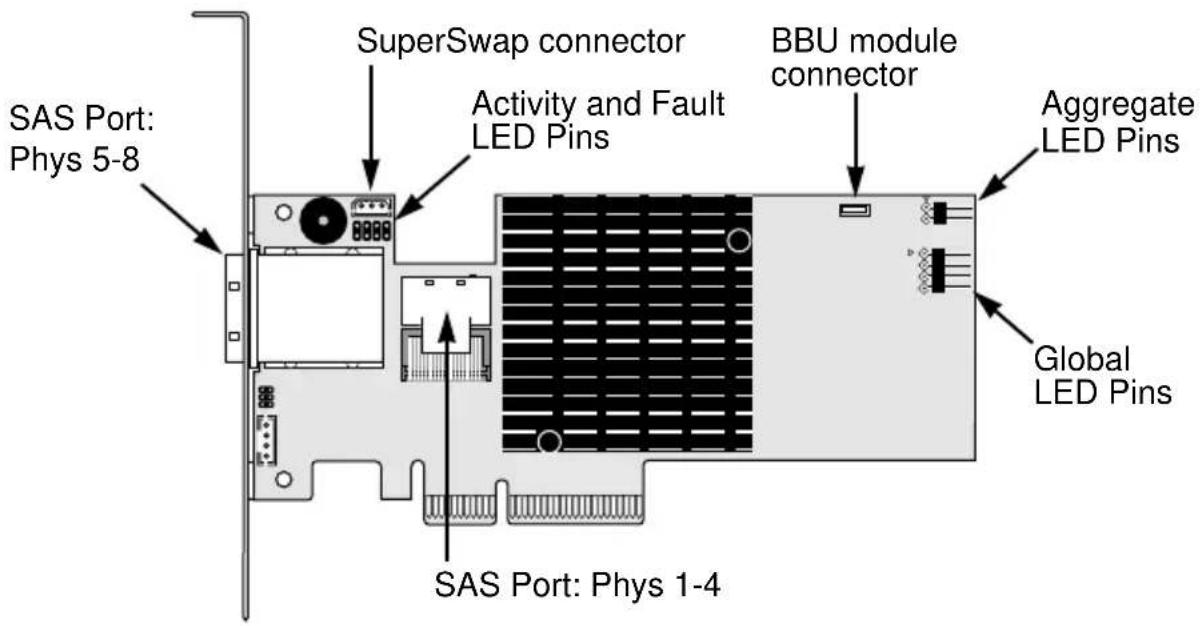
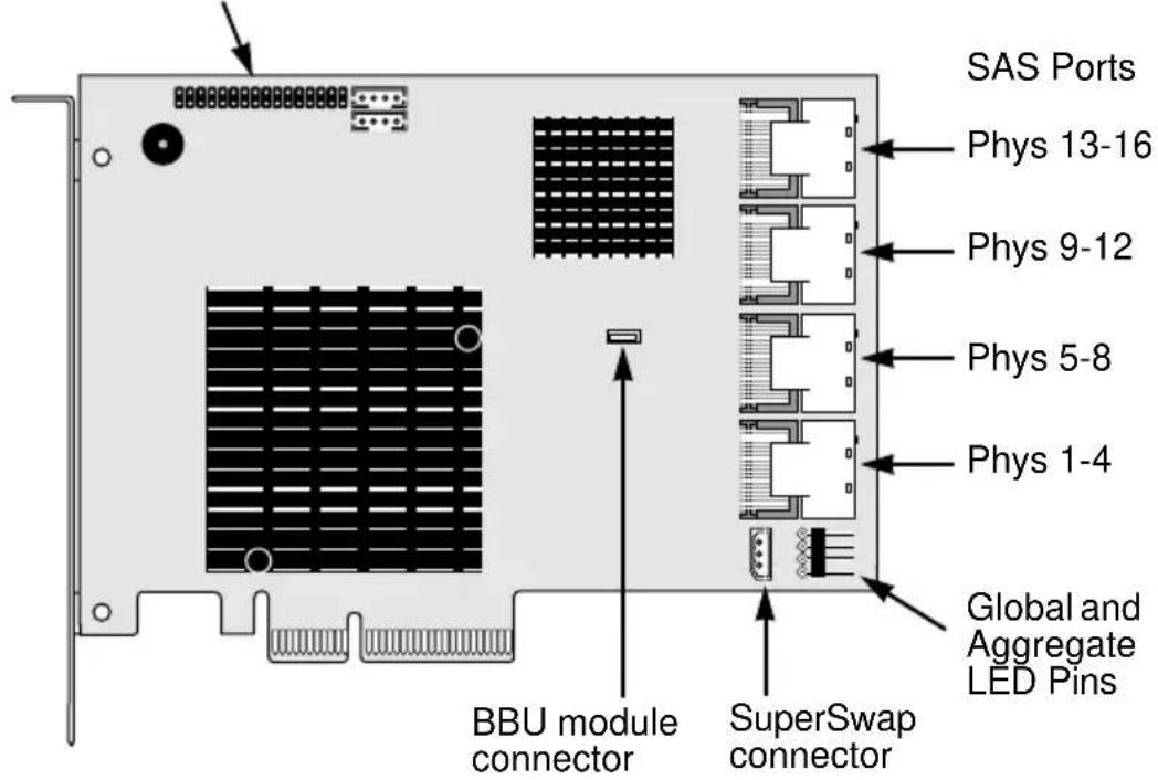
Figure 4. SuperTrak EX8658 card
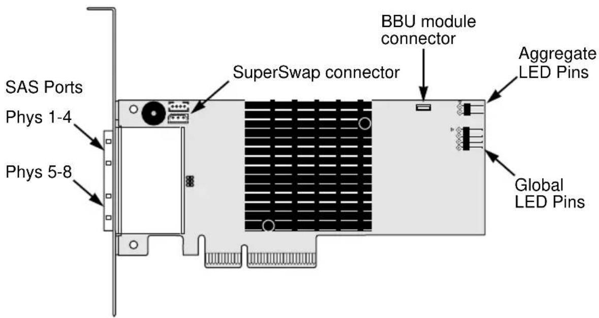
Figure 5. SuperTrak EX16650 card
Activity and Fault LED Pins
- Attach the other end of the SAS multi-lane cable to a SAS port on your enclosure's backplane or to your SAS expander.
For more information, see the user manual for your enclosure or SAS expander.
- Optional. Repeat steps 5 and 6 for the other SAS ports on the SuperTrak EX8650, EX8654, EX8658, or 16650 card.
- Optional. Attach cables from the LED pins on the SuperTrak card to the LEDs in your PC or enclosure. See Figures 5 through 7.
For more information, see "Appendix D: LED Backplane Connections" on page 295 and the user manual for your PC or enclosure.
Figure 6. Individual LED pins, EX4650, EX8650, and EX8654
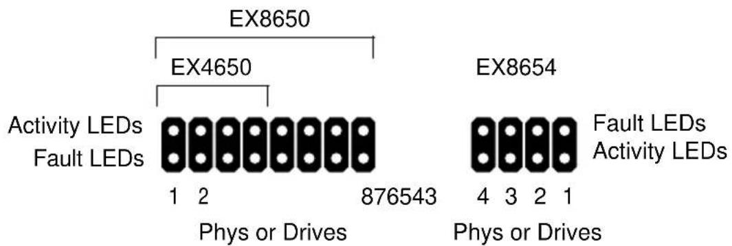
For SuperTrak EX8654 and EX8658, note that only the interior SAS Port Phys have individual LED pins.
Figure 7. Individual LED pins, EX16650

Activity LEDs
Fault LEDs
Phys or Drives
Global LEDs (J2)
+ RG +
Figure 8. Global and Aggregate LED pins, EX4650 and EX8650
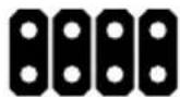
+ - - +
Aggregate LEDs (J3)
Figure 9. Global and Aggregate LED pins, EX8654 and EX8658
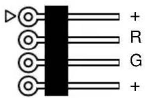
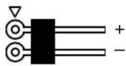
Aggregate LEDsGlobal LEDs
Figure 10. Global and Aggregate LED pins, EX16650
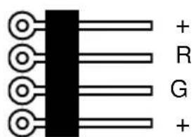
Global LEDs
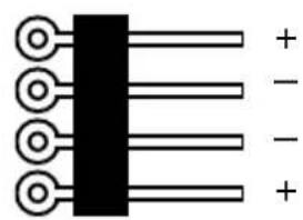
Aggregate LEDs
Connecting SuperTrak to a SuperSwap Enclosure
If you are using Promise SuperSwap enclosures:
- Attach SAS fanout cables to the SAS ports of the SuperTrak card.
- Connect the other ends of the SAS fanout cables to the SuperSwap enclosure.
- Connect the 3-to-3 pin management cable (came with the SuperSwap) from the SuperSwap connector on SuperTrak card to the Management connector on the back of the SuperSwap housing.
- Optional. If you are installing multiple SuperSwap 4600s, install a 6-pin daisy-chain cable from the daisy-chain OUT connector of the first SuperSwap to the daisy-chain IN connector of the second.
SuperTrak supports up to eight SuperSwap 1600 enclosures or up to two SuperSwap 4600 enclosures.
Connecting SuperTrak to a VTrak JBOD Enclosure
If you are connecting the SuperTrak card to a single VTrak JBOD enclosure, you can attach the SAS multi-lane cable to either the circle or diamond port on the enclosure.
However, if you plan to cascade multiple VTrak JBOD enclosures, you must attach the SAS multi-lane cable to the circle port on the first enclosure.
Figure 11. Attaching the SAS multi-lane cable to the diamond port
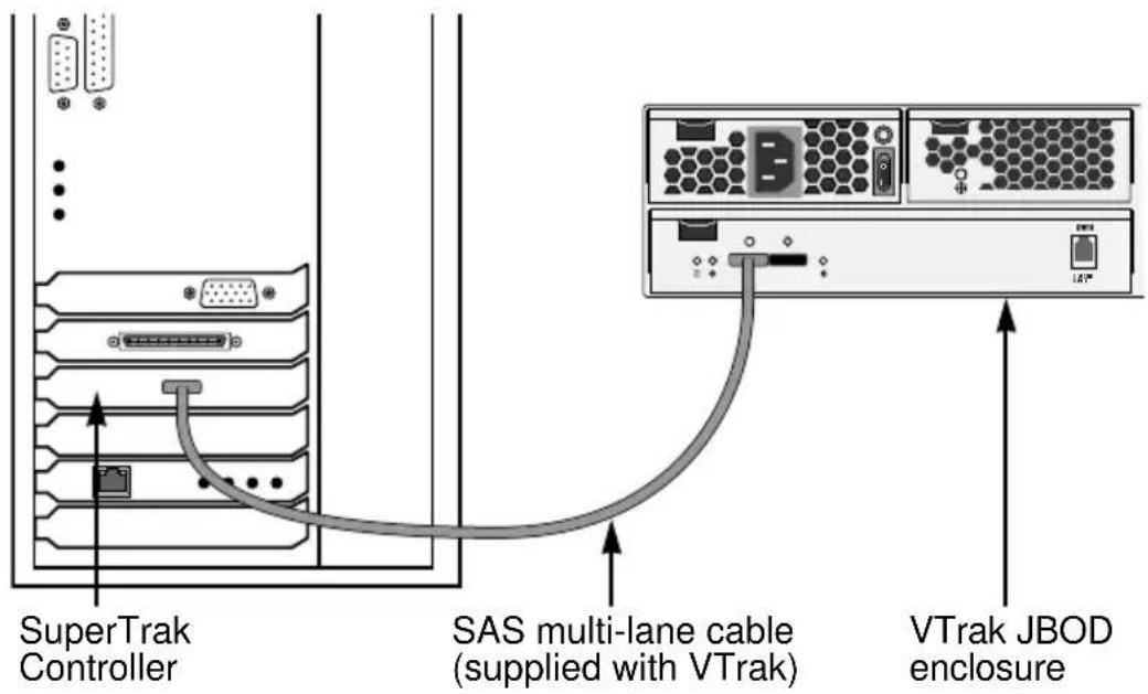
SAS Connections and ID Numbers
The table below correlates the ranges of Enclosure IDs and Physical Drive IDs, that appear in the WebPAM PRO interface as a result of the data connections you make.
| SuperTrak SAS Port | Enclosure ID Range Drive ID Range | |
| Phys 1-4 Virtual* 1 to 128 | ||
| Phys 1-4 2 to 9 | 1 to 128 | |
| Phys 5-8 10 to 17 | 129 to 256 | |
| Phys 9-12 18 to 25 | 257 to 384 | |
| Phys 13-16 26 to 33 | 385 to 512 | |
| * A virtual enclosure involves physical drives attached directly to the SuperTrak controller or a connection to an SGPIO backplane.You can attach up to 128 SAS or SATA drives on each SAS port using SAS expanders. | ||
The SuperTrak EX8650, EX8654, and EX8658 cards are designed to manage up to 16 enclosures and up to 256 SAS or SATA disk drives (using SAS expanders).
The SuperTrak EX16650 card is designed to manage up to 32 enclosures and up to 512 SAS or SATA disk drives (using SAS expanders).
If your system has fewer components, you might be surprised at the way WebPAM PRO numbers your enclosures and drives. The following scenarios illustrate some numbering examples.
Scenario 1: Virtual Enclosure – SGPIO
You install the SuperTrak card into an SGPIO enclosure. You attach a SAS data cable between SAS Port Phys 1-4 and the enclosure's backplane.
In WebPAM PRO, the SGPIO enclosure appears as Enclosure 1. The drives are numbered 1 to 128.
If you attached a second SGPIO enclosure to SAS Port Phys 5-8, it would appear in WebPAM PRO as Enclosure 10. The drives would be numbered 129 to 256.
Scenario 2: Virtual Enclosure – Host PC
You install the SuperTrak card into a Host PC. You attach SAS breakout cables to SAS Ports Phys 1-4 and Phys 5-8 and a SAS or SATA drive at the drive ends of each cable.
In WebPAM PRO, the Host PC appears as Enclosure 1. The drives on SAS Port Phys 1-4 are numbered 1 to 4. The drives on SAS Port Phy 5-8 are numbered 129 to 132.
This scenario also applies if you use Promise SuperSwap enclosures.
Scenario 3: External Enclosures – Daisy Chain
You install the SuperTrak card into a Host PC. You attach a SAS data cable between SAS Port Phys 1-4 and a Promise VTrak J310s 12-drive JBOD enclosure. You connect a second J310s enclosure to the first in a daisy chain.
In WebPAM PRO, the first JBOD enclosure appears as Enclosure 2. The drives are numbered 1 to 12. The second JBOD enclosure appears as Enclosure 3. The drives are numbered 13 to 24.
Scenario 4: External Enclosures – Parallel
You install the SuperTrak card into a Host PC. You attach a SAS data cable between SAS Port Phys 1-4 and a VTrak J310s enclosure. You attach a SAS data cable between SAS Port Phys 5-8 and a second J310s enclosure.
In WebPAM PRO, the first JBOD enclosure appears as Enclosure 2. The drives are numbered 1 to 12. The second JBOD enclosure appears as Enclosure 10. The drives are numbered 129 to 140.
Scenario 5: SAS Expanders
You install the SuperTrak card into a Host PC. You attach a SAS data cables between SAS Port Phys 1-4 and Phys 5-8 and two SAS Expanders.
In WebPAM PRO, the first Expander appears as Enclosure 2. The drives are numbered 1 to 128. The second Expander appears as Enclosure 10. The drives are numbered 129 to 256.
See “Viewing Enclosure Information” on page 148 and “Locating a Physical Drive” on page 149 for more information.
Choosing the Physical Drives
The SuperTrak EX Controller card supports:
- SAS physical drives
• SATA 3.0-Gb/s physical drives
• SATA 1.5-Gb/s physical drives - Hard Disk Drives (HDD)
• Solid State Drives (SSD)
For optimal performance, install physical drives of the same model and capacity.
| Level Number of Drives Level | Number of Drives |
| RAID 0 1 or more RAID 6 4 to 16* | |
| RAID 1 2 only RAID 10 4 or more** | |
| RAID 1E 3 or more RAID 50 6 or more | |
| RAID 5 3 to 16* RAID 60 8 or more | |
| * Requires SAS expansion** Requires an even number of drives | |
The table above shows the number of drives required for each RAID level.

Note
You cannot mix HDDs and SSDs in the same disk array. If you attempt to create an array with HDDs and SSDs, the Controller will create two separate disk arrays, each with the specified number of logical drives.
Creating a Logical Drive
You can use the SuperBuild™ Configuration Utility to create a logical drive with the attached physical drives. Even if you plan to use the WebPAM PRO software to manage your logical drives, you can still create your first logical drive using the SuperBuild Utility, as described here.

Note
For an explanation of the logical drive concepts and the choices you can make when you create your logical drive, see "Chapter 7: Technology Background" on page 227 of this manual.
- Boot your system. If this is the first time you have booted with the SuperTrak card and physical drives installed, the SuperTrak BIOS will display the following screen.
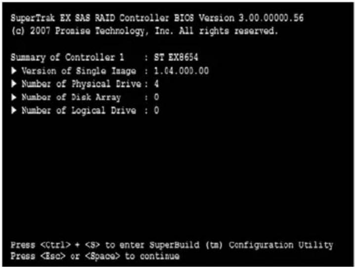
- Press the Ctrl-S keys to display the SuperBuild Utility Main Menu.
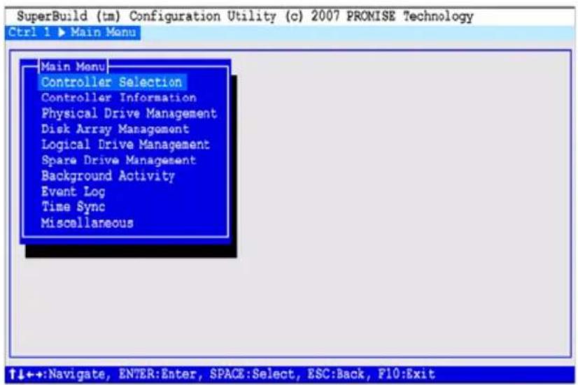
- Press the arrow keys to highlight Disk Array Management and press Enter.
![[Main Menu] Controller Selection Controller Information Physical Drive Management Disk Array Management Logical Drive Management Spare Drive Management Background Activity Event Log Time Sync Miscellaneous](/content/2026/05/785299/images/ea6db062794f07df63b999efa1e0b3f501ba356628bd7e28556c0b8150b9daad.jpg)
The Disk Array Management screen appears.
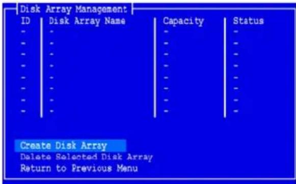
- Highlight Create Disk Array and press Enter.
The Create Disk Array screen appears.
![[Create Disk Array] Disk Array Name : DA1 Select Physical Drives : ID Model Name Capacity Status *1 WDC WD1600YS 153.25 GB Ok *2 WDC WD1600YS 153.25 GB Ok *3 WDC WD1600YS 153.25 GB Ok 4 WDC WD1600YS 153.25 GB Ok - - - - - - - - - - - - - - - Save Configuration Return to Previous Menu](/content/2026/05/785299/images/60540efc9fc8219ead0f26841096c4d6cb57656fecfa51785cb2e462a8b47daa.jpg)
Use this screen to select the physical drives for your disk array.
- Press the arrow keys to highlight a physical drive. Then press the spacebar to select the physical drive.
An asterisk (*) appears at the left of each selected physical drive.
- Highlight Save Configuration and press Enter.
The Disk Array Management screen appears, showing your new disk array
- Highlight Return to Previous Menu and press Enter.
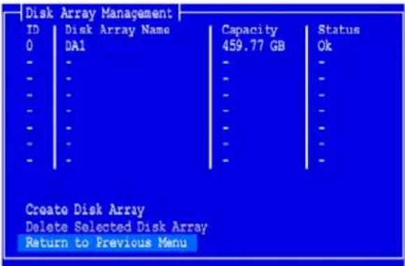
The Main Menu appears.
- Highlight Logical Drive Management and press Enter.
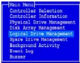
The Logical Drive Management screen appears.
- Highlight Create Logical Drive and press Enter.
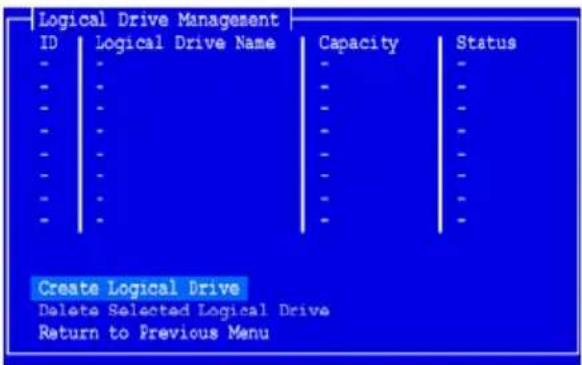
The Create Logical Drive Step 1/2 screen appears.
- Press the arrow keys to highlight a disk array. Then press the spacebar to choose the disk array.
An asterisk (*) appears at the left of the chosen disk array.
- Highlight Next Step and press Enter.
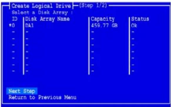
The Create Logical Drive Step 2/2 screen appears.
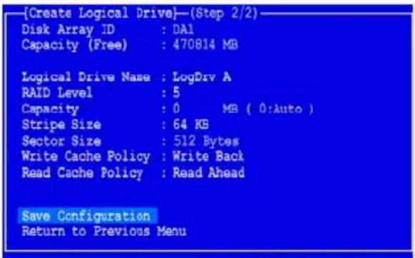
- To change the RAID Level, highlight RAID Level and press Enter.
In the popup menu, highlight your choice of RAID Level and press Enter. The available RAID Levels depend on the number of physical drives you selected for your disk array. - Press the arrow keys to highlight Logical Drive Name. Type a name for your logical drive and press Enter.
- To use less than the full physical drive capacity for this logical drive, highlight Capacity and press Enter.
Press the Delete or Backspace keys to erase the current capacity. Type the new capacity in MB to allocate to this logical drive.
Later, you can assign the unused capacity to a second logical drive.
- To change the Stripe Size, highlight Stripe Size and press Enter.
Highlight your choice of 64 KB, 128 KB, 256 KB, 512 KB, or 1024 KB and press Enter.
- To change the Sector Size, highlight Sector Size and press Enter.
Use the default 512 B. Only exceptions are logical drives larger than 2 TB on Windows XP 32-bit. See page 253 for more information.
- To change the Write Cache Policy, highlight Write Cache Policy and press Enter.
Highlight your choice of Write Through or Write Back and press Enter.
- To change the Read Cache Policy, highlight Read Cache Policy and press Enter.
Highlight your choice of None, Read Cache, or Read Ahead and press Enter.
- Highlight Save Configuration and press Enter.
The Logical Drive Management screen appears with your new logical drive.
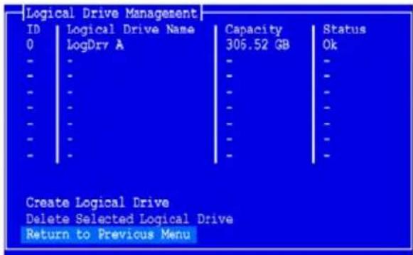
At this point you can create additional logical drives, if there is physical drive space available. To create another logical drive, repeat steps 4 though 18 above.
- Press the F10 key to exit the SuperBuild utility and press Y to confirm and restart the computer.
Do not press the Ctrl-Alt-Del keys. Do not press the Esc key.
You have successfully created a new RAID logical drive.

Important
You must partition and format your new logical drive before you can use it. Use the same method of partitioning and formatting a logical drive as you would any other fixed disk added to your computer system.
Installing the CLI
The Command Line Interface (CLI) provides rapid setup of disk arrays and logical drives. You can also manage your SuperTrak system using the CLI.
Installing onto Windows
To install the CLI onto your Windows PC or server:
-
Boot the PC or server, launch Windows, and log in as the Administrator. If the computer is already running, exit all programs. If you are not logged in as the Administrator, log out, then log in again as the Administrator.
-
Insert the Software CD into your CD-ROM drive.
The installer window opens automatically.
- Click the CLI/SNMP button, then click the Install CLI for Windows button.
The first CLI installation dialog box appears.
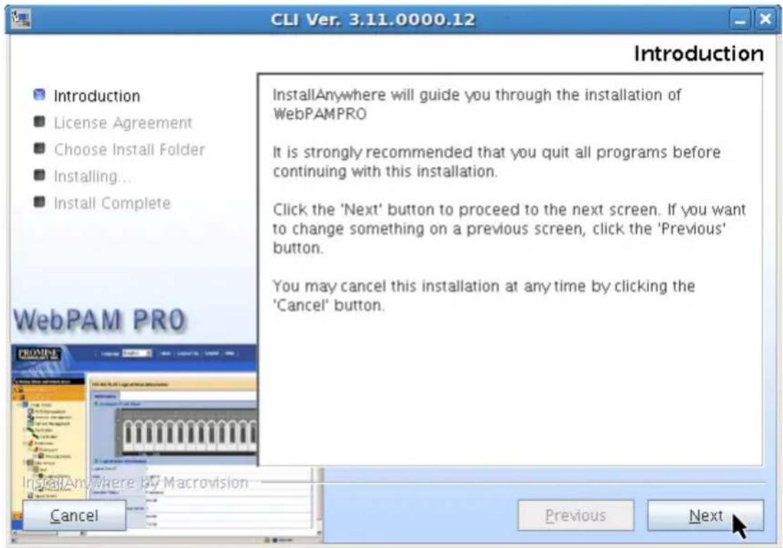
- In the Introduction dialog box, click the Next button to proceed with installation.
Figure 12. Introduction dialog box
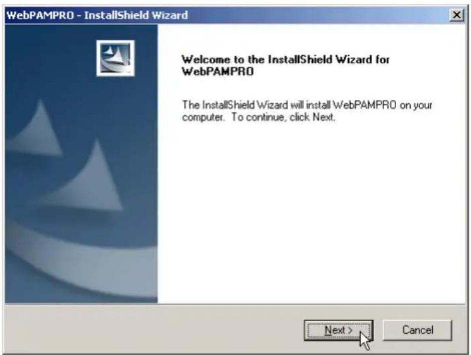
The CLI uses the same installer as WebPAM PRO. Even though the dialog boxes say "WebPAM PRO," this procedure installs the CLI.
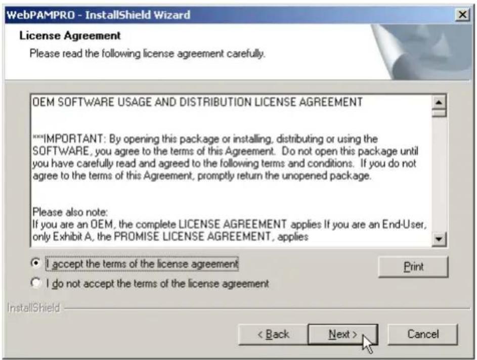
- In the License Agreement dialog box, choose the I accept... option, then click the Next button.
Figure 13. License Agreement dialog box
-
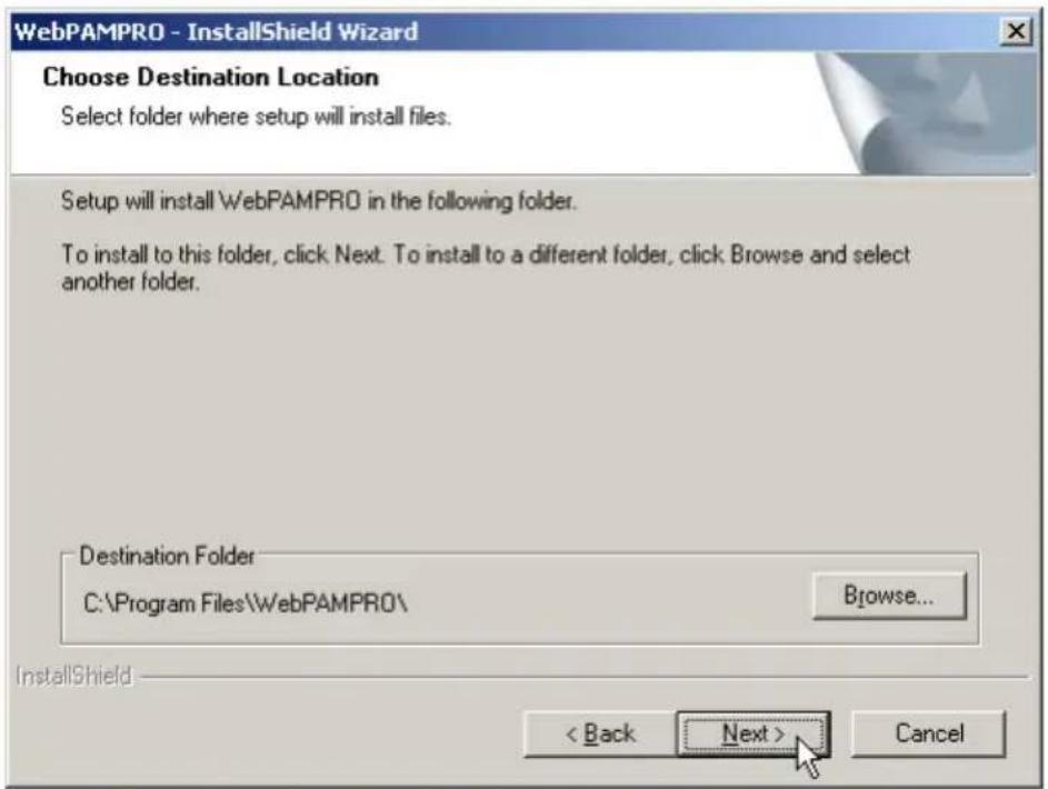
In the Choose Destination Location dialog box, you can:
-
Accept the default installation folder (recommended)
- Specify a different installation folder (advanced users)
When you agree with the proposed installation folder, click the Next button.
Figure 14. Choose Destination Location dialog box
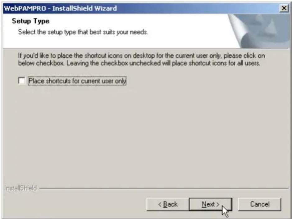
- In the Setup type dialog box, check the box if you only want to create desktop shortcut (right) for the current user.
Leave the box unchecked to create a desktop shortcut for all users.
Click the Next button to continue.

Figure 15. Setup Type dialog box
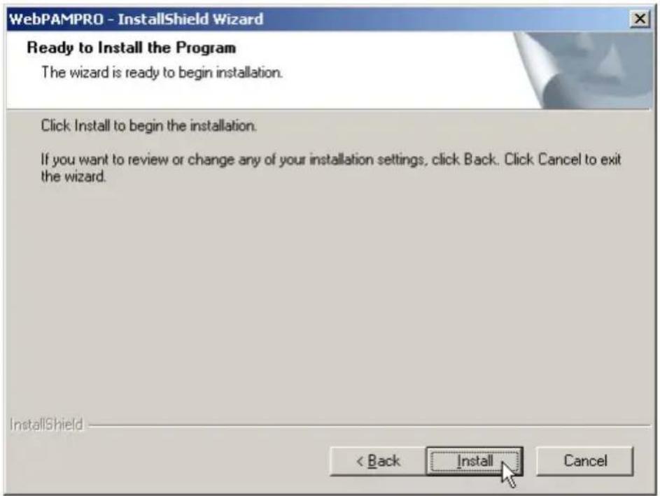
- In the Ready to Install dialog box, click the Install button to continue.
Figure 16. Ready to Install dialog box
- In the Install Complete dialog box, click the Finish button to exit the installer.
Figure 17. Install Complete dialog box
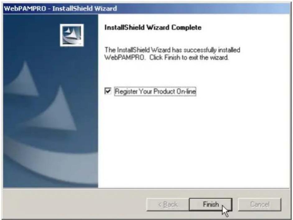
With the Register Your Product Online box checked, your browser will open and go directly to the Promise product registration website. Thank you for taking the time to register.
To open the CLI, click the CLI icon on the desktop (right).
Go to "Chapter 6: Management with the CLI" on page 185 for information about using this application.

Installing onto Linux

Important
Check the SuperTrak Read Me file for any issues pertaining to the distribution and version of Linux OS running on your PC or server.
For Linux PCs, Promise offers two different binary files:
- WebPAM PRO and CLI – Installs either or both WebPAM PRO and the CLI
- CLI only – Installs only the CLI
Note that both of these binary files open in a terminal window and both files use the WebPAM PRO installer. The procedure below installs the CLI only. To install WebPAM PRO, see page 49.
To install the CLI onto your Linux PC or server:
-
Boot the PC or server, log in as root, and launch the Linux GUI.
If the computer is already running, exit all programs. If you are not logged in as root, log out, then log in again as root. -
Insert the Software CD into your CD-ROM drive.
-
Copy the CLI_Installer...linux.bin file from the Software CD \CLI/Linux directory to the /root directory on your PC.
-
Open a terminal window and type sh followed by one space, the exact name of the CLI_Installer...linux.bin file, then press Enter.

Note
For silent installation, type sh followed by the exact name of the CLI_Installer...linux.bin file, followed by -i silent, then press Enter.
After several moments, the first installation dialog box appears.
- In the Introduction dialog box, click the Next button to proceed with installation.
Figure 18. Introduction dialog box
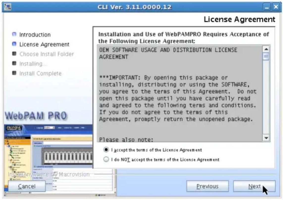
- In the License Agreement dialog box, choose the I accept... option, then click the Next button.
Figure 19. License Agreement dialog box
-
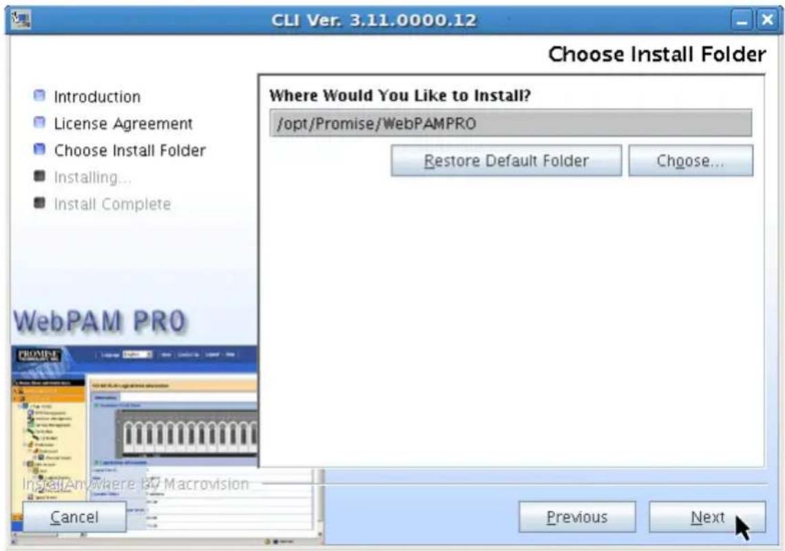
When the Choose Install Folder dialog box appears, you can:
-
Accept the default installation folder (recommended)
- Specify a different installation folder (advanced users)
When you agree with the proposed installation folder, click the Next button.
Figure 20. Choose Install Folder dialog box
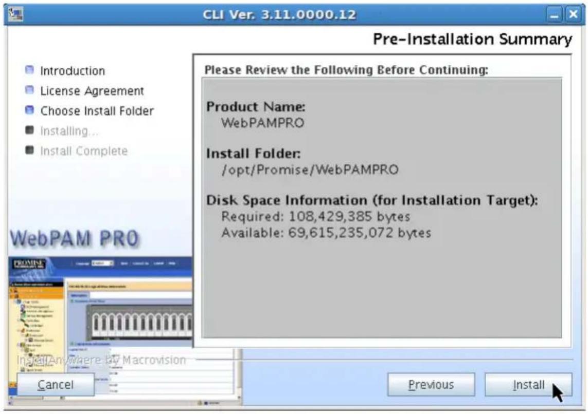
- In the Pre-Installation Summary dialog box, click the Install button to continue.
Figure 21. Pre-Installation Summary dialog box
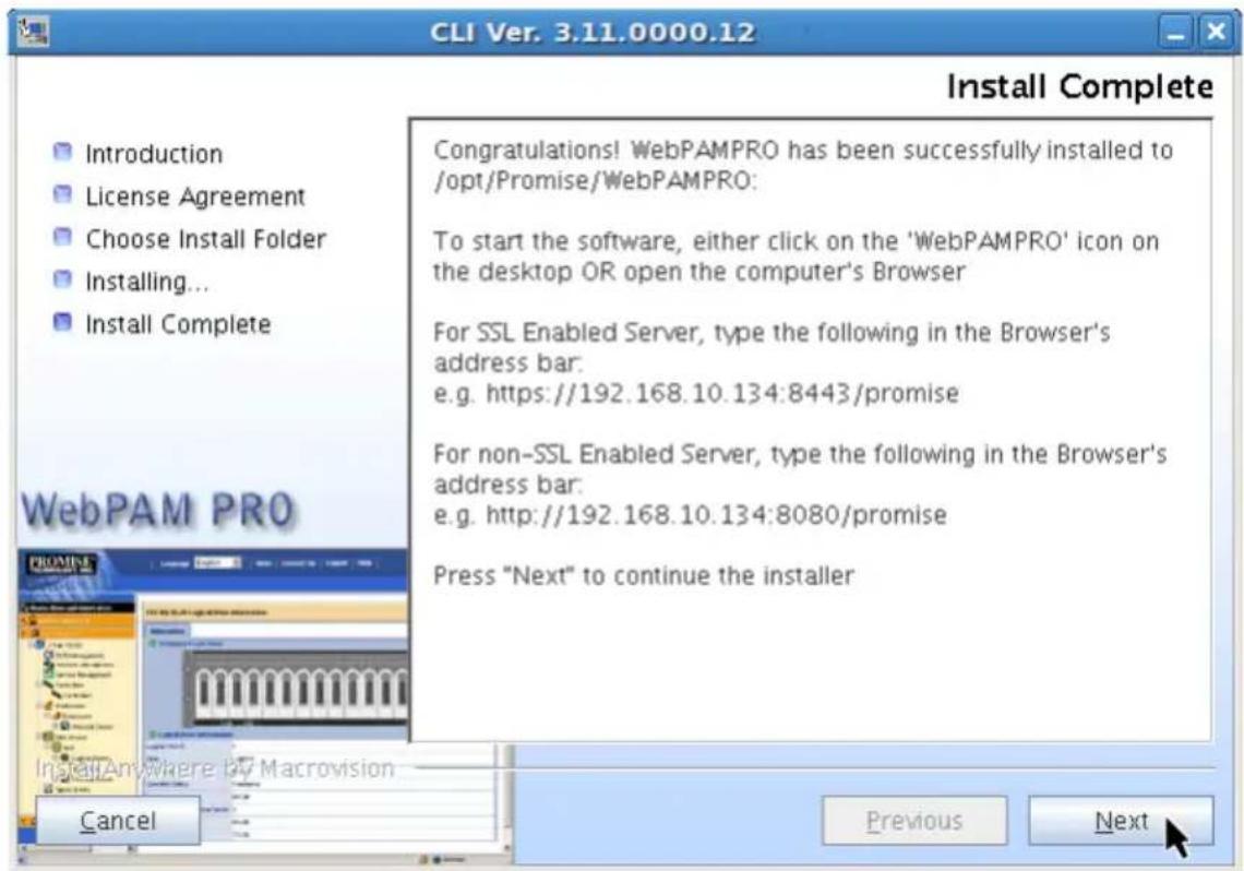
- In the Install Complete dialog box, click the Next button to continue.
Figure 22. Install Compete dialog box
- In the Register On-line dialog box, click the Done button to exit the installer
Figure 23. Register On-line dialog box
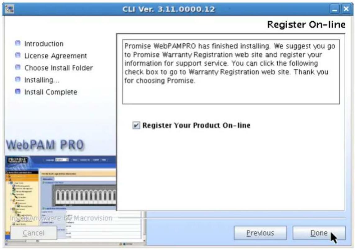
With the Register Your Product On-line box checked, your browser will open and go directly to the Promise product registration website. Thank you for taking the time to register.
Go to the /opt/Promise/WebPAMPRO/Agent/bin directory and type ./cllib to start the CLI.
Go to “Chapter 6: Management with the CLI” on page 185 for information about using this application.
Installing the CLI onto FreeBSD
PCs running FreeBSD do not support WebPAM PRO, therefore they cannot use the WebPAM PRO installer. Those systems use a binary file to install the CLI in a terminal window.
Choose the x64 binary file for a 64-bit OS or the x86 binary file for a 32-bit OS.
To install the CLI onto your FreeBSD PC or server:
-
Boot the PC or server, log in as root.
If the computer is already running, exit all programs. If you are not logged in as root, log out, then log in again as root. -
Insert the Software CD into your CD-ROM drive.
-
Copy the CLI_Installer...FreeBSD.bin file from the Software CD \CLI\FreeBSD directory to the /root directory on your PC.
-
Open a terminal window and type
sh CLI_Installer...FreeBSD.bin -i silent
and press Enter.
CLI_Installer...FreeBSD.bin represents the exact name of the CLI binary file, such as
CLI_Installer_3_11_0000_00_x64FreeBSD.bin, or
CLI_Installer_3_11_0000_00_x86FreeBSD.bin
- Reboot the PC or server.
After the installation is finished, type cliib with any shell to start the CLI.
Go to “Chapter 6: Management with the CLI” on page 185 for information about using this application.
Installing the CLI onto VMware
The VMware virtualization platform does not support WebPAM PRO, therefore they cannot use the WebPAM PRO installer. Those systems use a binary file to install the CLI in a terminal window.
Before you begin, download the CLI_Installer...VMware.bin file from the Promise Support Website to your PC or server.
To install the CLI onto your VMware platform:
- Boot the PC or server, log in as root. If the computer is already running, exit all programs. If you are not logged in as root, log out, then log in again as root.
- Copy the CLI_Installer...VMware.bin file to the /root directory on your PC.
- Open a terminal window and type sh CLI_Installer...VMware.bin -i silent and press Enter.
CLI_Installer...VMware.bin represents the exact name of the CLI binary file, such as CLI_Installer_3_11_0000_00_VMware.bin
After the installation is finished, go to the /opt/Promise/WebPAMPRO/Agent/bin directory and type ./clii b to start the CLI.
Go to “Chapter 6: Management with the CLI” on page 185 for information about using this application.
Installing WebPAM PRO
Web-Based Promise Array Management—Professional (WebPAM PRO) software provides a browser-based graphic user interface used to monitor and manage Promise RAID products and their logical drives. Because it works over your network, it can monitor and control multiple systems.
WebPAM PRO involves four components:
• Utility Server – Enables RAID management over a network
• Agent – Enables the Host PC to communicate with the Utility Server
- Java Runtime Environment (JRE) – A private installation for WebPAM PRO
- Internet Browser – Comes with your OS
When you install WebPAM PRO on a PC or server, you are installing the Utility Server, Agent, and JRE.
• Utility Server (page 38)
- Agent (page 38)
- JRE (page 39)
- Internet Browser (page 39)
- Installing WebPAM PRO onto Windows (page 40)
- Installing WebPAM PRO onto Linux (page 49)
Utility Server
The Utility Server can run on the Host PC (where the SuperTrak card is installed), or on a networked PC, if your WebPAM PRO system includes remote management over a network. You run the Utility Server by directing your browser to the IP address of the Host PC.
Agent
The Agent runs on the Host PC (where the SuperTrak card is installed). After you have logged into the Utility Server through WebPAM PRO, the Utility Server accesses the Agent on the Host PC. As the user, you do not access the Agent directly.
Operating System Support
On the Host PC where you install the SuperTrak controller and WebPAM PRO, Promise Technology recommends:
- Windows Server 2008 (64 bit) with or without Hyper-V
• Windows Server 2008 (32 bit) -
Windows Vista (32 or 64 bit)
-
Windows Server 2003 SP1, SP2; R2 (32 or 64 bit)
- Windows XP Professional SP2, SP3 (32 or 64 bit)
• Red Hat Enterprise Linux 4.4, 4.5, 4.6, 4.7, 5.0, 5.1, 5.2 (32 or 64 bit) - openSUSE 10.2, 10.3, 11 (32 or 64 bit)
• SLES 10, 10 SP1, 10 SP2 (32 or 64 bit) - Miracle Linux 4 SP2, 5 (32 or 64 bit)
• Fedora Core 6, 7, 8, 9 (32 or 64 bit) - Open Source Driver for Linux 2.6 kernel (32 or 64 bit)
Choose one of these operating systems to take full advantage of all the features of WebPAM PRO.
JRE
The WebPAM PRO installation program installs a private Java Runtime Environment (JRE) under the same directory where WebPAM PRO is installed. WebPAM PRO uses this private JRE to avoid incompatibility issues with any other JREs that may be present on your system.
Internet Browser
Typically an Internet browser comes with your operating system. The WebPAM PRO installer does not include a browser. For computers that will remotely monitor and manage the RAID, the browser is the only software required.
Browser Support
Choose the latest version of the following browsers to use with WebPAM PRO:
- Internet Explorer
- Fire fox
- Netscape Navigator
If you do not have one of the above browsers on the Host PC, install the browser first and make it the default browser. Then install WebPAM PRO.

Important
Install the SuperTrak driver for your operating system before installing WebPAM PRO. See “Chapter 3: Installing Drivers” on page 63 for instructions.

Caution
If you have WebPAM or an earlier version of WebPAM PRO on your PC or server, manually uninstall them before you install WebPAM PRO from the Software CD.
Go to one of the following procedures:
- "Installing WebPAM PRO onto Windows" on page 40.
- "Installing WebPAM PRO onto Linux" on page 49.
Installing WebPAM PRO onto Windows
To install WebPAM PRO onto your Windows-based PC or server:
-
Boot the PC or server, launch Windows, and log in as the Administrator. If the computer is already running, exit all programs. If you are not logged in as the Administrator, log out, then log in again as the Administrator.
-
Insert the Software CD into your CD-ROM drive.
The installer window opens automatically.
- Click the WebPAM PRO Software button, then click the Install WebPAM PRO for Windows button.
The first WebPAM PRO installation dialog box appears.
- In the Introduction dialog box, click the Next button to proceed with installation.
Figure 24. Introduction dialog box
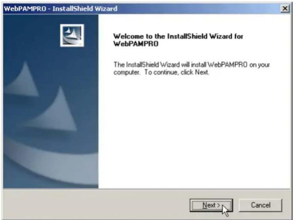
- In the License Agreement dialog box, choose the I accept... option, then click the Next button.
Figure 25. License Agreement dialog box
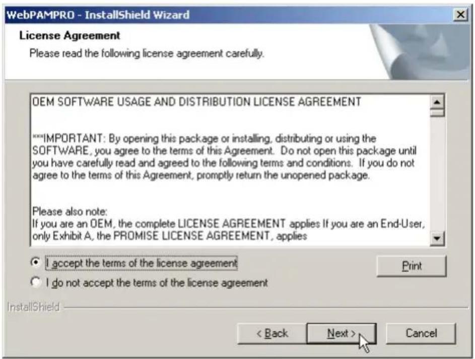
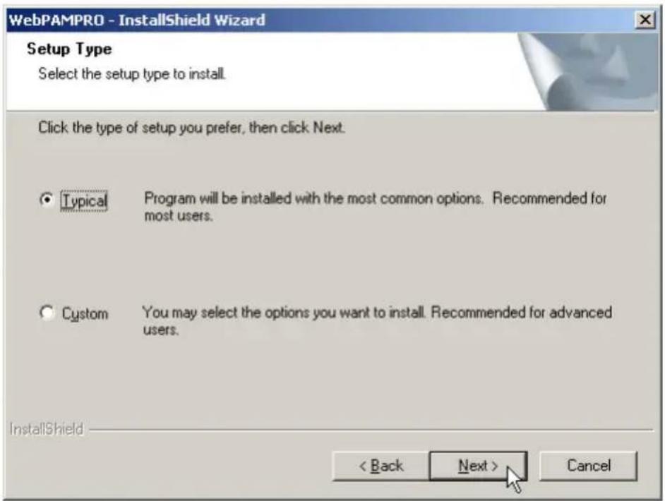
-
In the Setup Type dialog box, choose the option you prefer:
-
Typical – Installs the Agent, Server, and CLI. Recommended for most users.
- Custom – Enables you to choose which components to install. Optional for advanced users.
Click the Next button to continue.
Figure 26. Setup Type dialog box
-
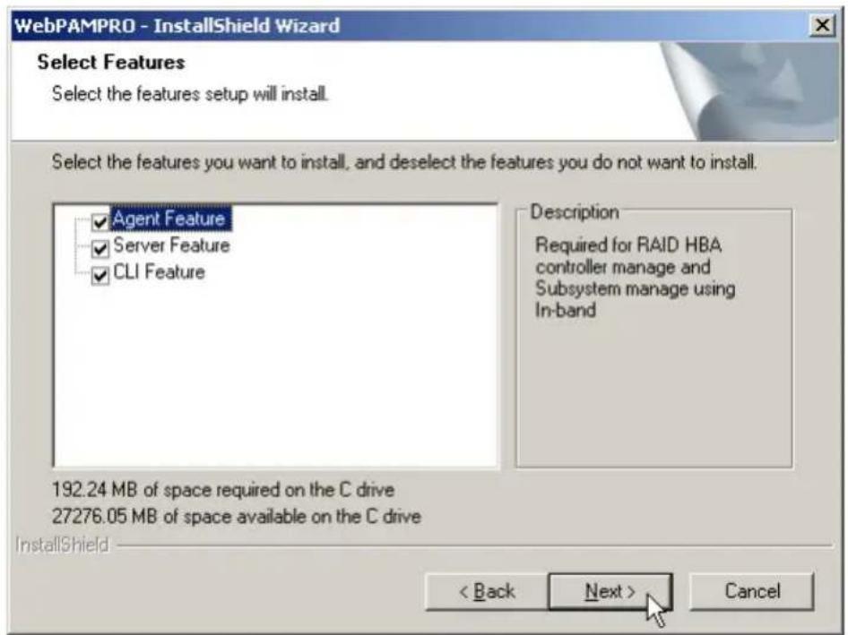
Optional. If you chose the Custom option, the Select Features dialog box appears. Choose any combination of three options:
-
Agent Feature – The Agent is required on the Host PC (where the SuperTrak card is installed) and for In-band management of subsystems.
- Server Feature – The Utility Server is required for local or remote management. If you have a network, install the Server on one of your networked PCs. If you have only local management, install the Server on the Host PC (where the SuperTrak card is installed).
- CLI Feature – The Command Line Interface runs on the Host PC (where the SuperTrak card is installed) and provides local management only.
Checked items will be installed. Uncheck items you do not want to install.
Click the Next button to continue.
Figure 27. Custom Setup dialog box
-
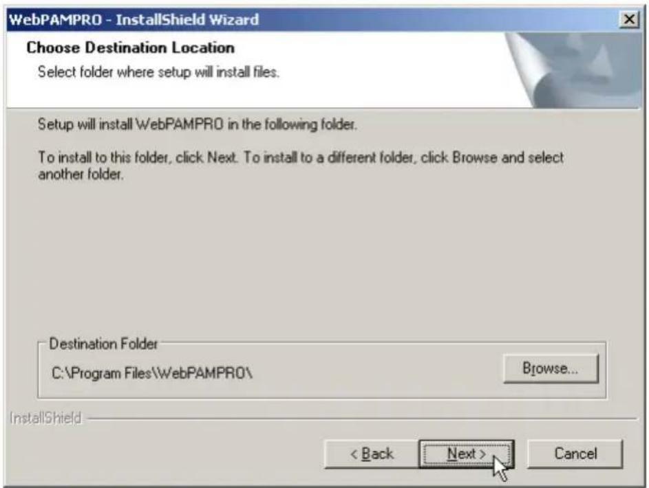
In the Choose Destination Location dialog box, you can:
-
Accept the default installation folder. Recommended for most users.
- Specify a different installation folder. Optional for advanced users.
When you agree with the proposed installation folder, click the Next button.
Figure 28. Choose Destination Location dialog box
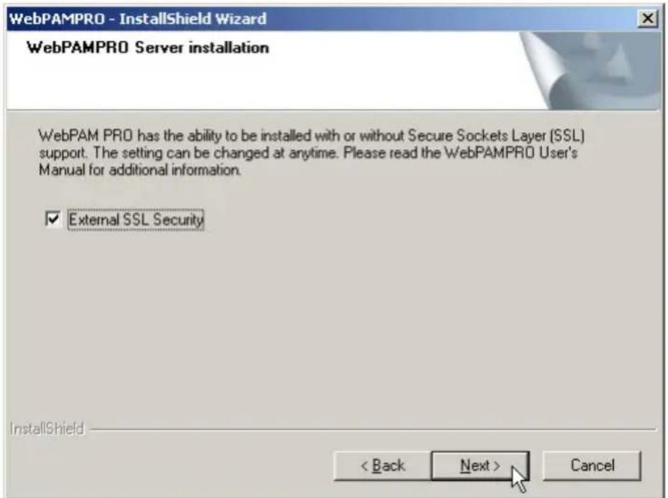
- In the WebPAM PRO Server dialog box, check the box to select SSL security.
External SSL Security – Applies security to all connections involving the Internet or outside your company firewall.
Security options are invisible to authorized users.
Promise Technology provides a default certificate for the server as well as for internal data communication. However, in some cases it is better to install and verify your own certificate for the webserver. And, if possible, verify the certificate by a certificate authority such as Verisign or Thwate. See your MIS Administrator for guidance.
Click the Next button to continue.
Figure 29. WebPAM PRO Server dialog box

Note
If you are only installing the CLI, this dialog box does not appear.
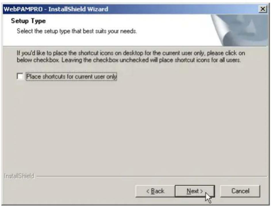
- In the Setup type dialog box, check the box if you only want to create desktop shortcut (right) for the current user.
Leave the box unchecked to create a desktop shortcut for all users.
Click the Next button to continue.
Figure 30. Setup Type dialog box
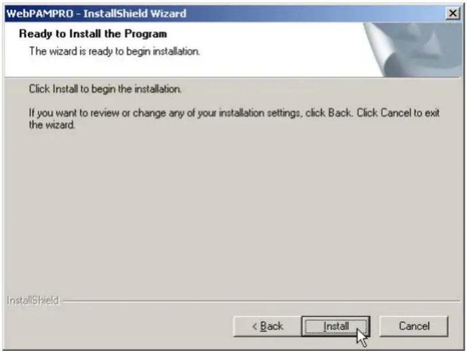
- In the Ready to Install dialog box, click the Install button to continue.
Figure 31. Ready to Install dialog box
- In the Install Complete dialog box, click the Finish button to exit the installer.
Figure 32. Install Complete dialog box
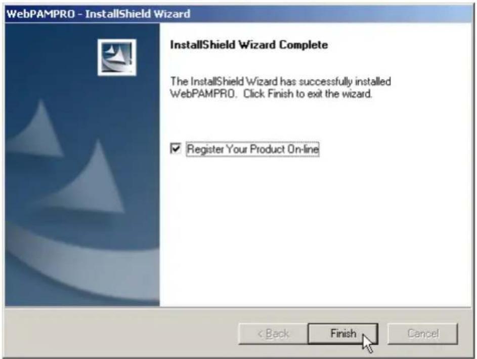
With the Register Your Product Online box checked, your browser will open and go directly to the Promise product registration website. Thank you for taking the time to register.
This completes the WebPAM PRO installation for Windows. Go to "Logging into WebPAM PRO" on page 58.
Installing WebPAM PRO onto Linux

Important
Check the SuperTrak Read Me file for any issues pertaining to the distribution and version of Linux OS that you are running.
To install WebPAM PRO onto your Linux-based PC or server:
- Boot the PC or server, log in as root, and launch the Linux GUI.
If the computer is already running, exit all programs. If you are not logged in as root, log out, then log in again as root. - Insert the Software CD into your CD-ROM drive.
- Go to the WebPAM PRO / Linux directory on the CD-ROM and copy the WebPAMPRO...Linux.bin file to the root directory.
- Open a terminal window and type sh followed by the exact name of the WebPAMPRO...Linux.bin file, then press Enter.

Note
For silent installation, type sh followed by the exact name of the WebPAMPRO...linux.bin file, followed by -i silent, then press Enter.
After several moments, the first WebPAM PRO installation dialog box appears.
- In the Introduction dialog box, click the Next button to proceed with installation.
Figure 33. Introduction dialog box

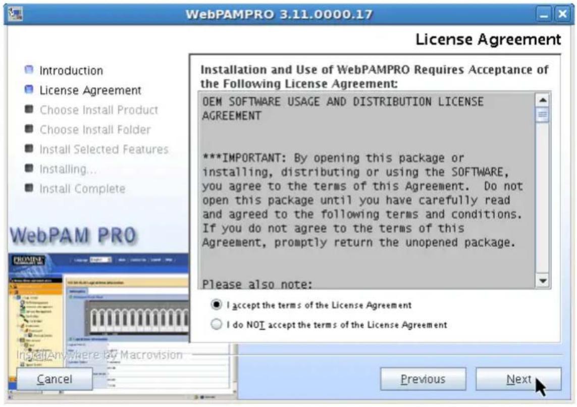
- In the License Agreement dialog box, choose the I accept... option, then click the Next button.
Figure 34. License Agreement dialog box
-
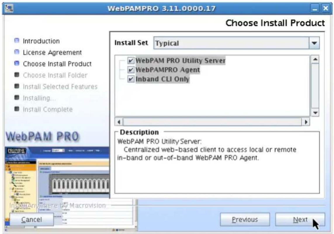
In the Choose Install Product dialog box, choose any combination of three options:
-
WebPAM PRO Utility Server – One Server must be installed on the network, or on the Host PC if there is only local management
- WebPAM PRO Agent – The Agent must be installed on every PC or Server where a SuperTrak Controller card has been installed
- Inband CLI Only – Installs the Command Line Interface (CLI) You can install the CLI now or at a later time.
Checked items will be installed. Uncheck items you do not want to install.
Click the Next button to continue.
Figure 35. Choose Install Product dialog box
-
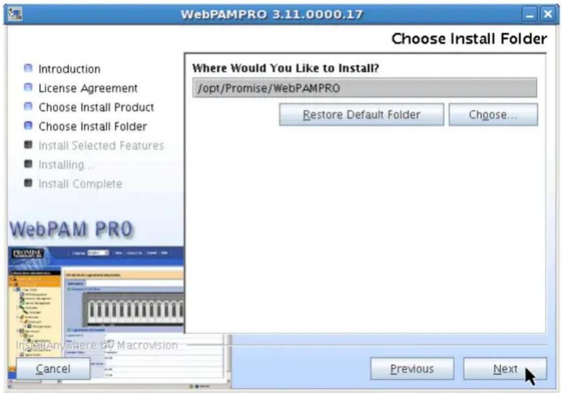
When the Choose Install Folder dialog box appears, you can:
-
Accept the default installation folder. Recommended for most users.
- Specify a different installation folder. Optional for advanced users.
When you agree with the proposed installation folder, click the Next button.
Figure 36. Choose Install Folder dialog box
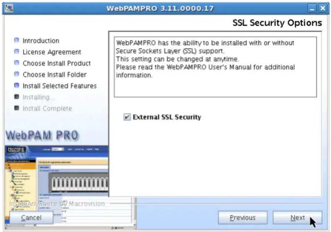
- In the SSL Security Options dialog box, check the box to select SSL security.
External SSL Security – Applies security to all connections involving the Internet or outside your company firewall.
Security options are invisible to authorized users.
Promise Technology provides a default certificate for the server as well as for internal data communication. However, in some cases it is better to install and verify your own certificate for the webserver. And, if possible, verify the certificate by a certificate authority such as Verisign or Thwate. See your MIS Administrator for guidance.
Click the Next button to continue.
Figure 37. SSL Security Options dialog box

Note
If you are only installing the CLI, this dialog box does not appear.
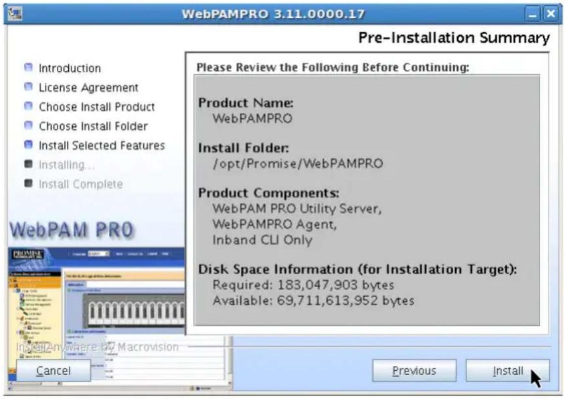
- In the Pre-Installation Summary dialog box, click the Install button to continue.
Figure 38. Pre-Installation Summary dialog box
- In the Install Complete dialog box, click the Next button to continue.
Figure 39. Install Compete dialog box
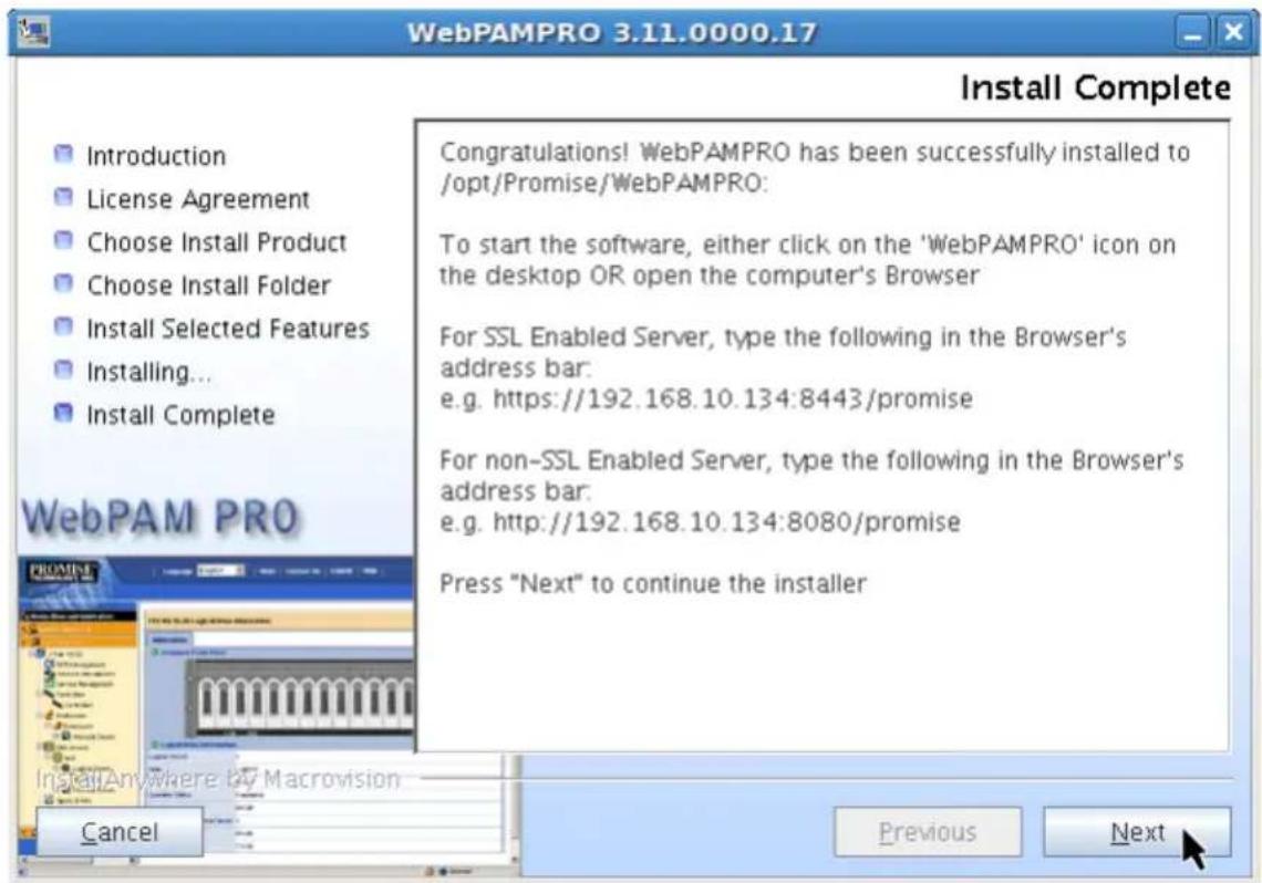
- In the Register On-line dialog box, click the Done button to exit the installer
Figure 40. Register On-line dialog box
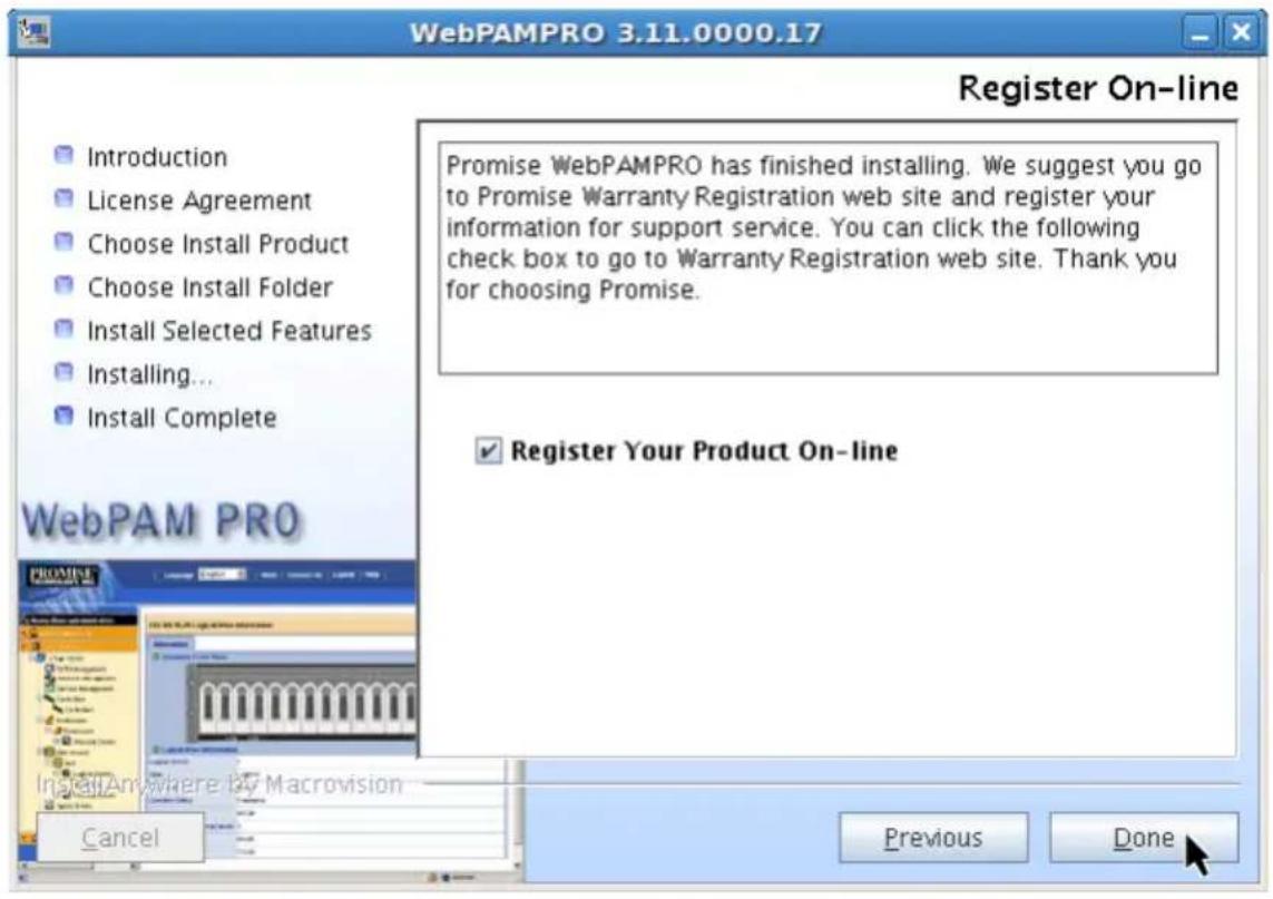
With the Register Your Product On-line box checked, your browser will open and go directly to the Promise product registration website. Thank you for taking the time to register.

Note
The first time you install WebPAM PRO on a RedHat Linux system, the WebPAM PRO icon appears on the desktop but not in the application menu. Please log out, then log in again, and the WebPAM PRO icon will thereafter appear in the application menu.
This completes the WebPAM PRO installation for Linux. Go to "Logging into WebPAM PRO" on page 58.
Logging into WebPAM PRO
You can log into WebPAM PRO in either of two ways:
- Logging in at the Host PC (page 58)
- Logging in over the Network (page 58)
Logging in at the Host PC
At the Host PC (where the SuperTrak EX Controller is installed), do one of the following actions:
- Double-click the WebPAM PRO desktop icon.
- Choose WebPAM PRO in the Windows Programs menu.
- Choose WebPAM PRO in the Linux Applications menu.
- Follow the steps under "Logging in over the Network".
Logging in over the Network
You can log into WebPAM PRO from any PC with a network connection to the Host PC (where the SuperTrak EX Controller is installed).
- Launch your Browser.
- In the Browser address field, type the information provided below, then press Enter.
If you selected External SSL Security during installation (Windows, see page 45; Linux, see page 54), use the Secure Connection. Otherwise, use the Regular Connection.
Regular Connection
- WebPAM PRO uses an HTTP connection....http://
- Enter the Host PC's IP address.... 192.168.10.228
- Enter the Port number .....:8080
- Add promise to launch WebPAM PRO ....../promise
Together, your entry looks like this: http://192.168.10.228:8080/promise
Secure Connection
- WebPAM PRO uses a secure HTTP connection....https://
- Enter the Host PC's IP address.... 192.168.10.228
- Enter the Port number .....:8443
- Add promise to launch WebPAM PRO ....../promise
Together, your entry looks like this:
https://192.168.10.228:8443/promise

Notes
- You can enter the Host PC's network name in place of the IP address.
- If you are logging in at the Host PC, you can enter localhost in place of the IP address.
- Whether you select a regular or a secure connection, your WebPAM PRO user name and password are always secure.
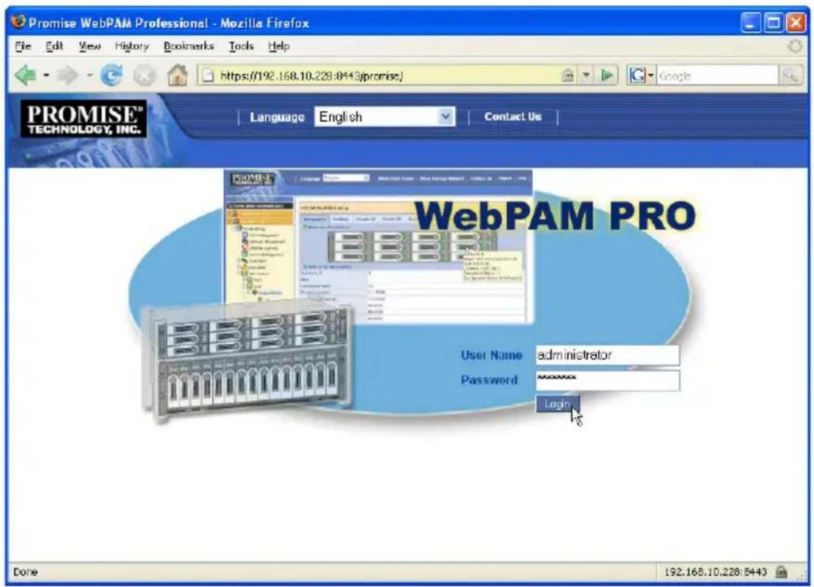
Login Screen
When the opening screen appears:
- Type administrator in the User Name field.
- Type password in the Password field.
- Click the Login button.
The User Name and Password are case sensitive. See Figure 41.
Figure 41. The WebPAM PRO login screen
Setting up WebPAM PRO
The first time you use WebPAM PRO, you must add the Host PC so that WebPAM PRO will recognize it. You only need to perform this procedure once.
To add the Host PC:
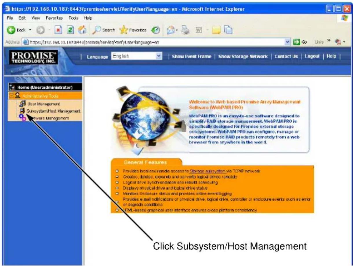
- In the Tree, click Subsystem/Host Management.
See Figure 42.
Figure 42. WebPAM PRO initial login screen
- Click the Add Subsystem/Host tab.
- In the Subsystem/Host Port IP address field, type the IP address of the Host PC where you installed the SuperTrak EX Controller card.
If you are working at the same Host PC where the SuperTrak card is installed, you can also type 127.0.0.1 in the IP address field.
Entries such as localhost or the Host PC's network name do not work for this function.
Figure 43. Add Subsystem/Host tab
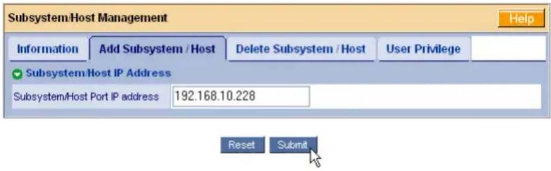
- Click the Submit button.
The newly added host appears in the Tree, on the left side of the WebPAM PRO screen.
This completes the WebPAM PRO installation and initial setup. Go to "Chapter 5: Management with WebPAM PRO" on page 109 for information about using this application.
Chapter 3: Installing Drivers
- Driver Installation Media
- Windows (page 64)
• Linux and FreeBSD (page 65)
- Windows Server 2008
- New OS Installation (page 66)
- Existing System (page 67)
- Confirming Driver Installation (page 67)
- Windows Vista
- New OS Installation (page 68)
- Existing System (page 69)
- Confirming Driver Installation (page 69)
- Windows Server 2003
- New OS Installation (page 70)
- Existing System (page 71)
- Confirming Driver Installation (page 71)
- Windows XP
- New OS Installation (page 72)
- Existing System (page 73)
- Confirming Driver Installation (page 73)
• Red Hat Linux Enterprise 4.4, 4.5, 4.6, 4.7
- New OS Installation (page 74)
- Existing System (page 74)
- Fedora Core 6
- New OS Installation (page 75)
• Existing System (page 75)
- Fedora Core 7, 8
- New OS Installation (page 76)
- Existing System (page 76)
- openSUSE 10.2, 10.3, 10.5, 11
- New OS Installation (page 77)
• Existing System (page 77)
• SLES 10, 10 SP1, 10 SP2
- New OS Installation (page 78)
- Existing System (page 78)
- Miracle Linux 4
- New OS Installation (page 80)
- Existing System (page 81)
• FreeBSD 6.1, 6.2, 6.3, 7.0
- New OS Installation (page 80)
- Existing System (page 81)
• VMware ESX Server 3.0.2, 3.5.0
- New OS Installation (page 82)
- Existing System (page 82)
Following are installation procedures for the SuperTrak drivers for Windows, Linux, and FreeBSD included on the software CD.
Download the latest drivers from the Promise Support Website.
The software CD also includes source code files for compiling your own Linux drivers. Source code files begin with the letters SRC.

Important
If you are using a Linux distribution for which there are no compiled drivers, please access the Promise Knowledge Base and call up Article 10029.
Driver Installation Media
Windows
If your Windows PC does not have a floppy drive, copy the driver file to a CD or a USB stick, whichever your PC supports.
To prepare a driver diskette, CD, or USB stick for Windows:
- Insert the software CD into your CD-ROM drive.
- Click the Driver button.
- Click the Driver for Windows button.
-
Click the button for your Windows system:
-
XP – Windows SCSIPort Driver
-
All other versions – Windows STORPort Driver
-
Insert a blank diskette, a writable CD, or attach a USB memory stick to your PC.
- Copy the driver file to the diskette, CD, or USB stick.
Check the driver's ReadMe file for important information.
Linux and FreeBSD
For FreeBSD, start with a diskette. For Linux, choose the medium that works for your system.
If your Linux PC does not have a floppy drive, copy the driver file to a CD or a USB stick, whichever your PC supports.
To prepare a driver diskette, CD, or USB stick for Linux:
- Insert the software CD into your CD-ROM drive.
- Click the Driver button.
- Click the button for your OS:
- Driver for Miracle Linux
- Driver for RedHat / Fedora
- Driver for SUSE
- Driver for FreeBSD
- Double-click the folder for your OS version.
- Manually copy the driver .tar.gz file from the folder to your PC's hard drive.
- Open a terminal window and untar the driver file. Below is an example: tar zxvf RH-306010003.tar.gz
- Insert a blank diskette, a writable CD, or attach a USB memory stick to your PC.
- Copy the driver file to the diskette, CD, or USB stick. Check the driver's ReadMe file for important information.
Windows Server 2008
New OS Installation
The following details the installation of the SuperTrak EX Series RAID Controller drivers while installing Windows Server 2008.
- Start the installation: Boot from the CD-ROM.
- When the "Where do you want to install Windows?" dialog box appears, click Load Driver.
- Insert the SuperTrak driver diskette into drive A: or attach a USB memory stick with the SuperTrak driver to the USB port.
- In the Load Driver dialog box, click the Browse button.
- In the Browse for Folder dialog box, click the diskette or USB stick, then click the OK button.
- In the "Select the driver to be installed" dialog box, highlight Promise SuperTrak EX SAS RAID Controller, then click the Next button.
- When the "Where do you want to install Windows?" dialog box appears again, in the list of Disks, highlight the Disk representing your logical drive (the Disk with unallocated space), then click the Next button.
- Continue the Windows installation.
Existing System
After installing the SuperTrak EX Series RAID Controller card and rebooting your system, Windows Server 2008 setup will show a “Found New Hardware” dialog box.
- Choose the Locate and install driver software option and click the Next button.
The “Found New Hardware – RAID Controller” dialog box displays the message: “Allow Windows to search online for driver software for your RAID Controller?” - Choose the Don't search online option.
The “Found New Hardware – RAID Controller” dialog box displays the message: “Insert the disc that came with your RAID Controller.” - Insert the driver diskette into the floppy drive and click the Next button.
Windows loads the driver and displays the “Found New Hardware” dialog box with message: “Windows has finished installing the driver software for this device Promise SuperTrak EX SAS RAID Controller.” - Click the Close button to finish driver installation.
Confirming Driver Installation
- Right-click the My Computer icon and choose Manage from the popup menu.
- From the left panel, choose Device Manager.
- Click the + in front of Storage controllers. "Promise SuperTrak EX SAS RAID Controller" and "Promise RAID Console" should appear.
Windows Vista
New OS Installation
The following details the installation of the SuperTrak EX Series RAID Controller drivers while installing Windows Vista.
- Start the installation: Boot from the CD-ROM.
- When the "Where do you want to install Windows?" dialog box appears, click Load Driver.
- Insert the SuperTrak driver diskette into drive A: or attach a USB memory stick with the SuperTrak driver to the USB port.
- In the Load Driver dialog box, click the Browse button.
- In the Browse for Folder dialog box, click the diskette or USB stick, then click the OK button.
- In the "Select the driver to be installed" dialog box, highlight Promise SuperTrak EX SAS RAID Controller, then click the Next button.
- When the "Where do you want to install Windows?" dialog box appears again, in the list of Disks, highlight the Disk representing your logical drive (the Disk with unallocated space), then click the Next button.
- Continue the Windows installation.
Existing System
After installing the SuperTrak EX Series RAID Controller card and rebooting your system, Windows Vista setup will show a "Found New Hardware" dialog box.
- Choose the Locate and install driver software option and click the Next button.
The “Found New Hardware – RAID Controller” dialog box displays the message: “Allow Windows to search online for driver software for your RAID Controller?” - Choose the Don't search online option.
The “Found New Hardware – RAID Controller” dialog box displays the message: “Insert the disc that came with your RAID Controller.” - Insert the driver diskette into the floppy drive and click the Next button.
Windows loads the driver and displays the "Found New Hardware" dialog box with message: "Windows has finished installing the driver software for this device Promise SuperTrak EX SAS RAID Controller." - Click the Close button to finish driver installation.
Confirming Driver Installation
- Right-click the My Computer icon and choose Manage from the popup menu.
- From the left panel, choose Device Manager.
- Click the + in front of Storage controllers. "Promise SuperTrak EX SAS RAID Controller" and "Promise RAID Console" should appear.
Windows Server 2003
New OS Installation
The following details the installation of the SuperTrak EX Series RAID Controller drivers while installing Windows Server 2003.
-
Start the installation:
-
Floppy Install: Boot the computer with the Windows Server 2003 installation diskettes.
-
CD-ROM Install: Boot from the CD-ROM. Press F6 after the message "Press F6 if you need to install third party SCSI or RAID driver" appears.
-
When the Windows Server 2003 Setup window is generated, press S to specify an Additional Device(s).
- Insert the SuperTrak driver diskette into drive A: and press Enter.
- Choose Promise SuperTrak EX SAS RAID Controller from the list that appears on screen, and then press the Enter.
- The Windows Server 2003 Setup screen will appear again saying "Setup will load support for the following mass storage devices:" The list will include "Promise SuperTrak EX SAS RAID Controller".
NOTE: If there are any additional devices to be installed, specify them now. When all devices are specified, continue to the next step.
- From the Windows Server 2003 Setup screen, press the Enter. Setup will now load all device files and then continue the Windows Server 2003 installation.
Existing System
After installing the SuperTrak EX Series RAID Controller card and rebooting your system, Windows Server 2003 setup will show a “Found New Hardware” dialog box. Under Windows 2003, “RAID Controller” will be displayed.
- Insert the SuperTrak driver diskette into the A:\ drive.
- Choose Install the software automatically and press the Enter key.
- If using a driver that has not been digitally signed by Microsoft, you will be asked if you want to continue the installation. Click Continue anyway.
- When the New Hardware Wizard has finished installing the SuperTrak driver, click Finish.
Confirming Driver Installation
- Right-click the My Computer icon and choose Manage from the popup menu.
- From the left panel, choose Device Manager.
- Click the + in front of SCSI and RAID controllers. "Promise SuperTrak EX SAS RAID Controller" and "Promise RAID Console" should appear.
Windows XP
New OS Installation
The following details the installation of the SuperTrak EX Series RAID Controller drivers while installing Windows XP.
-
Start the installation:
-
Floppy Install: Boot the computer with the Windows XP installation diskettes.
-
CD-ROM Install: Boot from the CD-ROM. Press F6 after the message "Press F6 if you need to install third party SCSI or RAID driver" appears.
-
When the Windows XP Setup window is generated, press S to specify an Additional Device(s).
- Insert the SuperTrak driver diskette into drive A: and press Enter.
- Choose Promise SuperTrak EX SAS RAID Controller from the list that appears on screen, and then press the Enter.
- The Windows XP Setup screen will appear again saying "Setup will load support for the following mass storage devices:" The list will include "Promise SuperTrak EX SAS RAID Controller".
NOTE: If there are any additional devices to be installed, specify them now. When all devices are specified, continue to the next step.
- From the Windows XP Setup screen, press the Enter. Setup will now load all device files and then continue the Windows XP installation.
Existing System
After installing the SuperTrak EX Series RAID Controller card and rebooting your system, Windows XP setup will show a "Found New Hardware" dialog box.
- Insert the SuperTrak driver diskette into the A:\ drive.
- Choose Install the software automatically and press the Enter key.
- If using a driver that has not been digitally signed by Microsoft, you will be asked if you want to continue the installation. Click Continue anyway.
- When the New Hardware Wizard has finished installing the SuperTrak driver, click Finish.
Confirming Driver Installation
- Right-click the My Computer icon and choose Manage from the popup menu.
- From the left panel, choose Device Manager.
- Click the + in front of SCSI and RAID controllers. "Promise SuperTrak EX SAS RAID Controller" and "Promise RAID Console" should appear.
Red Hat Linux Enterprise 4.4, 4.5, 4.6, 4.7
New OS Installation
- Start the RedHat Linux Installation by booting from the install CD.
- At the "Welcome to Red Hat Linux..." installation screen, a prompt labeled boot: will appear at the bottom of the screen. Type linux dd and press Enter.
- When the Installer asks, "Do you have a driver disk?" click Yes.
- At the "Insert your driver disk and press OK to continue," click OK.
At the Devices dialog box, insert the driver diskette or CD, or attach the USB stick and click OK. - Continue with the installation normally.
Note: Check the readme file, included with the downloaded driver files, for instructions on installing the RAID Console.
Note: The RHEL 5 kernel includes a SuperTrak driver.
Existing System
- Insert the driver diskette or CD, or attach the USB stick.
- Log in as root.
- Type mount -r /dev/fd0 /mnt/floppy.
Change this command as needed for a CD or USB stick. -
Type cd /mnt/floppy
Change this command as needed for a CD or USB stick. -
Type sh ./install.
-
When the Installer asks, "You are installing a driver on an existing OS. Is it true (y/n)?" press Y, then press Enter.
-
Type cd /umount /mnt/floppy.
Change this command as needed for a CD or USB stick.
-
Remove the driver diskette, CD, or USB stick.
-
Type reboot to restart the system.
Fedora Core 6
New OS Installation
- Start the Fedora Core Installation by booting from the install CD.
- At the "Welcome to Fedora 6..." installation screen, a prompt labeled boot: will appear at the bottom of the screen. Type linux dd acpi=off and press Enter.
- When the Installer asks, "Do you have a driver disk?" click Yes.
- At the "Insert your driver disk and press OK to continue," click OK.
At the Devices dialog box, insert the driver diskette or CD, or attach the USB stick and click OK. - Continue with the installation normally.
Note: Include acpi=off in the boot script to ensure proper system startup.
Existing System
- Insert the driver diskette or CD, or attach the USB stick.
- Log in as root.
- Type mount -r /dev/fd0 /mnt/floppy.
Change this command as needed for a CD or USB stick. - Type cd /mnt/floppy
Change this command as needed for a CD or USB stick. - Type sh ./install.
- When the Installer asks, "You are installing a driver on an existing OS. Is it true (y/n)?" press Y, then press Enter.
- Type cd /umount /mnt/floppy.
Change this command as needed for a CD or USB stick. - Remove the driver diskette, CD, or USB stick.
- Type reboot to restart the system.
Note: Include acpi=off in the boot script to ensure proper system startup.
Fedora Core 7, 8
New OS Installation
- Start the Fedora Core Installation by booting from the install CD.
- At the “Welcome to Fedora...” installation screen, highlight the Install or upgrade an existing system option, then press the Tab key for edit options.
A prompt labeled boot: will appear at the bottom of the screen. - Type linux dd and press Enter.
- When the Installer asks, "Do you have a driver disk?" click Yes.
- At the "Insert your driver disk and press OK to continue," click OK.
At the Devices dialog box, insert the driver diskette or CD, or attach the USB stick and click OK. - Continue with the installation normally.
Note: For Fedora Core 7, include acpi=off in the boot script to ensure proper system startup.
Existing System
- Insert the driver diskette or CD, or attach the USB stick.
- Log in as root.
- Type mount -r /dev/fd0 /mnt/floppy.
Change this command as needed for a CD or USB stick. -
Type cd /mnt/floppy
Change this command as needed for a CD or USB stick. -
Type sh ./install.
-
When the Installer asks, "You are installing a driver on an existing OS. Is it true (y/n)?" press Y, then press Enter.
-
Type cd /umount /mnt/floppy.
Change this command as needed for a CD or USB stick.
-
Remove the driver diskette, CD, or USB stick.
-
Type reboot to restart the system.
Note: For Fedora Core 7, include acpi=off in the boot script to ensure proper system startup.
openSUSE 10.2, 10.3, 10.5, 11
New OS Installation
- Start the SUSE Linux Installation by booting from the install CD.
- As the system boots, press F6 for the driver diskette, CD, or USB stick.
- Choose the Yes option.
- Move the cursor to highlight the Installation option, then press Enter.
- When the Driver Update Menu pops up, choose your driver diskette, CD, or USB stick.
Then click OK and click Back to return to the installer. - Follow the on-screen prompts to complete the installation.
Existing System
- Insert the driver diskette or CD, or attach the USB stick.
- Log in as root.
- Type mount /dev/fd0 /media/floppy.
Change this command as needed for a CD or USB stick. - Type cd /media/floppy
Change this command as needed for a CD or USB stick. - Type sh ./install.
- Type cd /umount /media/floppy.
Change this command as needed for a CD or USB stick. - Remove the driver diskette, CD, or USB stick.
- Type reboot to restart the system.
SLES 10, 10 SP1, 10 SP2
New OS Installation
- Start the SLES Linux Installation by booting from the install CD.
- As the system boots, press F5 for the driver diskette, CD, or USB stick.
- Choose the Yes option.
- Move the cursor to highlight the Installation – ACPI Disabled option, then press Enter.
- When the Driver Update Menu pops up, choose your driver diskette, CD, or USB stick.
Then click OK and click Back to return to the installer. - Follow the on-screen prompts to complete the installation.
Existing System
- Insert the driver diskette or CD, or attach the USB stick.
- Log in as root.
- Type mount /dev/fd0 /media/floppy.
Change this command as needed for a CD or USB stick. - Type cd /media/floppy
Change this command as needed for a CD or USB stick. - Type sh ./install.
- Type cd /umount /media/floppy.
Change this command as needed for a CD or USB stick. - Remove the driver diskette, CD, or USB stick.
- Type reboot to restart the system.
Miracle Linux 4
New OS Installation
- Start the Miracle Linux Installation by booting from the install CD.
- At the "Asianux" installation screen, a prompt labeled boot: will appear at the bottom of the screen. Type linux dd and press Enter.
- When the Installer asks, "Do you have a driver disk?" click Yes.
- At the "Insert your driver disk and press OK to continue," insert the driver diskette or CD, or attach the USB stick and click OK.
- Continue with the installation normally.
Note: The Miracle Linux 5 kernel includes a SuperTrak driver.
Existing System
- Insert the driver diskette or CD, or attach the USB stick.
- Log in as root.
- Type mount -r /dev/fd0 /mnt/floppy.
Change this command as needed for a CD or USB stick. - Type cd /mnt/floppy
Change this command as needed for a CD or USB stick. - Type sh ./install.
- When the Installer asks, "You are installing a driver on an existing OS. Is it true (y/n)?" press Y, then press Enter.
- Type cd /umount /mnt/floppy.
Change this command as needed for a CD or USB stick. - Remove the driver diskette, CD, or USB stick.
- Type reboot to restart the system.
FreeBSD 6.1, 6.2, 6.3, 7.0
New OS Installation
- Start the FreeBSD Installation by booting from the install CD.
- When the console menu appears, choose 6. Escape to loader prompt and press any key except Enter to confirm your choice.
- Insert the driver diskette.
- Type the following commands and press Enter:
set currdev=disk0
load /stex.ko
set currdev=cd0
boot
- Remove the driver diskette and continue the installation.
- When the installation is finished, DO NOT EXIT.
Press Alt-F4 to switch to another screen. - Verify whether a device node exists. Type the following command and press Enter. Is /dev/fd0
Option 1. Device Node Exists
- Type the following commands and press Enter.
- After those commands finish, type the following command and press Enter. amount /cdrom
- Remove the driver diskette.
- Press Alt+F1, exit the installation, and reboot your PC.
mount -t msdos /dev/fd0 /cdrom /cdrom/install
Option 2. Device Node Does Not Exist
- Obtain a blank USB device, a disk drive or a memory stick, formatted to FAT or FAT32 (MSDOS).
- Copy the files from the driver diskette to the root directory of the USB device.
- Attach the USB device to the PC.
- Type the following commands and press Enter.
Where /dev/daXs is the device node for the USB device.
mount -t msdos /dev/daXsX /cdrom /cdrom/install
- After those commands finish, type the following command and press Enter. amount /cdrom
- Remove the USB device.
- Press Alt+F1, exit the installation, and reboot your PC.
Existing System
- Insert the driver diskette or CD, or attach the USB stick.
- Log in as root.
- Type mount -r /dev/fd0 /mnt/floppy.
Change this command as needed for a CD or USB stick.
- Type cd /mnt/floppy
Change this command as needed for a CD or USB stick.
- Type ./load.
- Type cd /umount /mnt/floppy.
Change this command as needed for a CD or USB stick.
- Remove the driver diskette, CD, or USB stick.
- Type reboot to restart the system.
VMware ESX Server 3.0.2, 3.5.0
New OS Installation
- Download the VMware driver ISO image from the Promise Support Website.
- Burn the VMware driver ISO image to a CD.
- Place the driver CD in the CD-ROM drive.
- Reboot the computer.
- When prompted for an upgrade or installation method, press Enter for graphical mode.
- Specify your language.
- Select a keyboard type.
- If your Driver CD successfully loaded, you will be prompted to insert the ESX Server CD and restart.
- Continue with the ESX Server installation.
Existing System
- Download the VMware driver ISO image from the Promise Support Website.
- Burn the VMware driver ISO image to a CD.
- Log into the system as the Superuser.
- Insert the driver CD into the CD-ROM.
If CD does not mount automatically, type the following command and press Enter:
mount /mnt/cdrom
- Type the following command and press Enter to install the driver RPM:
rpm -ivh /mnt/cdrom/VMupdates/RPMS/VMware-esx-drivers-scsi-stex-
If the installation fails due to conflicts, try installing with the --force option.
- Type the following commands and press Enter to update the boot file and regenerate GRUB:
esxcfg-boot -rg esxcfg-boot -b
If the ESX Server did not install on the SuperTrak EX controller, copy stex.o From /usr/lib/vmware/vmkmod/ To /lib/modules/2.4.xxxxx/kernel/drivers/scsi/
- Reboot ESX Server.
8. Remove the CD from the CD-ROM.
Note: If the driver did not load after the server rebooted, try one of the following actions to make the ESX Server reconfigure its hardware settings:
- Move the SuperTrak EX controller to a different slot.
- Remove the existing SuperTrak EX controller and install a different SuperTrak EX controller in its place.
Chapter 4: SuperBuild™ Utility
- SuperTrak BIOS (below)
- Accessing the Main Menu (page 88)
- Selecting a Controller (page 89)
- Viewing Controller Information (page 89)
- Managing Physical Drives (page 90)
- Managing Disk Arrays (page 92)
- Managing Logical Drives (page 95)
- Managing Spare Drives (page 99)
- Viewing Background Activity (page 102)
- Managing the Event Log (page 103)
- Working with Time Sync (page 105)
• Using the Miscellaneous Menu (page 106)
SuperTrak BIOS
This section explains the information that you can obtain from the SuperTrak BIOS.
When the SuperTrak BIOS loads during bootup, the BIOS displays pertinent information about the RAID logical drives. At this point, press Ctrl-S to enter the SuperBuild Configuration Utility.
The SuperTrak BIOS screen displays the following information:
• Summary of Controller – The SuperTrak controller model number.
- Version of Single Image – The version number of the image used to update the firmware on the SuperTrak controller.
• Number of Physical Drives – The number of physical drives attached to this controller.
• Number of Disk Arrays – The number of disk arrays managed by this controller.
• Number of Logical Drives – The number of logical drives managed by this controller.
See Figure 1.
Figure 1. SuperTrak BIOS screen
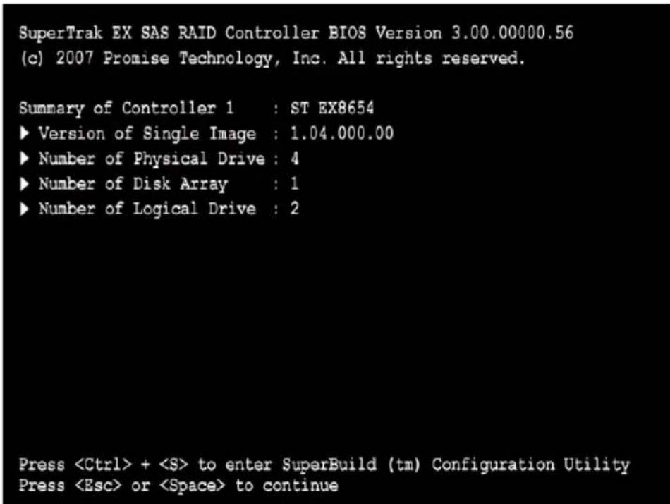
If the SuperBuild BIOS detects a Critical logical drive, the BIOS reports the condition:
Figure 2. SuperTrak BIOS screen, logical drive critical
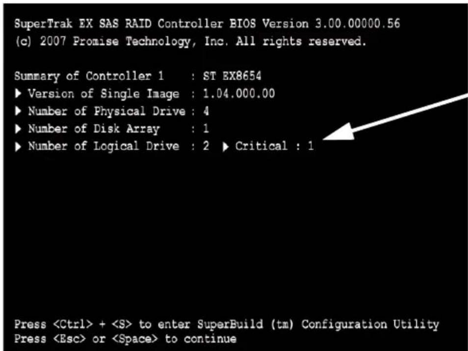
See “Critical & Offline Logical Drives” on page 267 for information about restoring an offline logical drive.
If the SuperTrak BIOS detects an Offline logical drive, the BIOS reports the condition and temporarily halts the booting process of the Host PC.
Figure 3. SuperTrak BIOS screen, logical drive offline
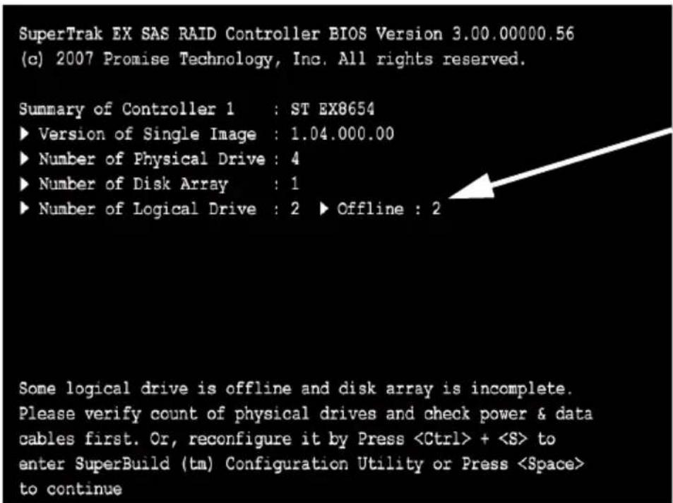
See "Critical & Offline Logical Drives" on page 267 for information about restoring an offline logical drive.
Accessing the Main Menu
The opening screen of the SuperBuild utility is the Main Menu.
Figure 4. SuperBuild Main Menu
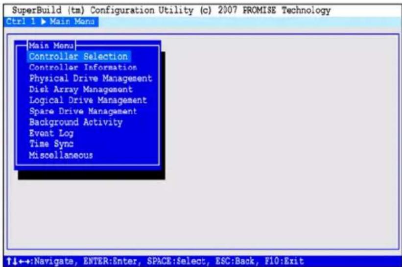
The Main Menu (above) has nine options:
- Controller Selection – Select which of two SuperTrak controllers you want to access, if you have two SuperTraks installed in the Host PC
- Controller Information – Memory type and size, Firmware and BIOS version numbers, and address information that may be helpful for diagnostic purposes
- Physical Drive Management – A list of physical drives attached to the SuperTrak controller, their ID (channel) numbers, model numbers, capacity, and status
- Disk Array Management – A list of disk arrays attached to the SuperTrak controller, the assigned physical drives, logical drives, capacity, and status
• Logical Drive Management – A list of logical drives plus create and delete logical drive functions
- Spare Drive Management—A list of hot spare drives, their characteristics and status
- Background Activity – A list of logical drives, any current background activity, logical drive status and percentage of activity completed. Background activities include: Rebuild, Initialize, Synchronize, Migrate, and Pause/Resume
• Event Log – A list of events stored in RAM (since startup) or non-volatile RAM (since the log was cleared) for diagnosis
- Time Sync – Enables you to set the time zone and synchronize system time and date with the embedded site
- Miscellaneous – SAS drive LEDs, enclosure management, and buzzer settings
Selecting a Controller
The SuperBuild Configuration utility supports up to two SuperTrak RAID Controller cards installed in the same Host PC. Controller selection enables you to select which of the two SuperTrak controllers the utility accesses.
If you have only one SuperTrak card installed in the Host PC, the SuperTrak is Controller 1, and no selection is necessary.
If you have two SuperTrak cards installed in the Host PC, take the following action to select one of them:
- In the Main Menu, highlight Controller Selection and press Enter.
- Highlight Controller 1 or Controller 2 and press Enter.
The selected controller (SuperTrak card) displays in the SuperBuild utility.
Viewing Controller Information
The SuperBuild utility displays information about the selected SuperTrak EX controller.
- In the Main Menu, highlight Controller Information and press Enter.
The information includes:
Vendor – Promise Technology, Inc.
Model – SuperTrak EX4650, 8650, 8654, EX8658, or EX16650
WWN – World Wide Number of the SuperTrak controller
Memory Type – DDR2 SDRAM
Memory Size - 128 MB, 256 MB, or 512 MB
Single Image Ver – The version number of the image used to update the firmware on the SuperTrak EX controller.*
Firmware Version – The version number of the firmware currently installed on the SuperTrak EX controller.*
BIOS Version – The version number of the BIOS currently installed on the SuperTrak EX controller.*
PCI Func Address – The functional address of the SuperTrak card in the Host PC. Used for advanced diagnostics
* The BIOS and Firmware are upgradable. See “Downloading BIOS and Firmware File” on page 289 and See “Updating the Firmware” on page 132.
- Highlight Return to Previous Menu and press Enter.
Managing Physical Drives
Physical drive management includes these functions:
• Viewing Physical Drives (page 90)
- Viewing Physical Drive Information (page 90)
- Managing Physical Drive Problems (page 91)
Viewing Physical Drives
To view physical drives:
-
In the Main Menu, highlight Physical Drive Management and press Enter.
The information includes:
ID – The channel number of the SuperTrak controller to which the physical drive is attached
Model Name – The physical drive manufacturer's model name for the drive
Capacity – Data capacity of the physical drive
Status – OK is normal. Can also show Rebuilding or Dead. -
Highlight Return to Previous Menu and press Enter.
Viewing Physical Drive Information
The SuperBuild utility displays information about the physical (disk) drives attached to the SuperTrak controller.
- In the Main Menu, highlight Physical Drive Management and press Enter.
- Highlight the physical drive you want to see and press Enter.
The Physical Drive Information screen displays:
ID – The channel number of the SuperTrak controller to which this physical drive is attached.
Model Name – The drive manufacturer's model name.
Serial Number – The drive manufacturer's serial number.
Firmware Version – The drive's firmware version number.
Drive Interface – SAS or SATA, 3.0 or 1.5 Gb/s
Protocol – ATA/ATAPI protocol level.
Capacity - Data capacity of the physical drive in GB.
Location – Enclosure refers to the Host PC. Slot refers to the channel number of the SuperTrak controller.
Configuration – Disk array number and sequence number, Type of spare drive, or Unconfigured.
Status – OK is normal. Can also show Rebuilding, Stale, or Dead.
- Highlight Return to Previous Menu and press Enter.
Managing Physical Drive Problems
Physical drives can develop problems that make them unsuitable for service in a logical drive. These problems are reflected in the physical drive status:
• P F A – The physical drive has errors resulting in a prediction of failure
• Stale – Caused by obsolete array information on the physical drive
- Offline – The physical drive is present but set to Offline status
- Dead – Physical drive set down by the SuperTrak controller
See “Chapter 8: Troubleshooting” on page 261 for corrective action.
Managing Disk Arrays
Disk array management includes these functions:
- Viewing Disk Arrays (page 92)
- Viewing Disk Array Information (page 92)
- Creating a Disk Array (page 93)
- Changing Disk Array Settings (page 94)
- Rebuilding a Disk Array (page 94)
- Deleting a Disk Array (page 94)
Viewing Disk Arrays
The SuperBuild utility displays information about the disk arrays managed by the SuperTrak controller.
- In the Main Menu, highlight Disk Array Management and press Enter.
The information includes:
ID – The consecutive number of the disk array in the order it was created, beginning with 0.
Disk Array Name – The name you assigned to the disk array.
Capacity - Data capacity of the disk array in GB.
Status – OK is normal. Can also show Rebuilding, Degraded, Critical, or Offline.
- Highlight Return to Previous Menu and press Enter.
Viewing Disk Array Information
To view disk array information:
-
In the Main Menu, highlight Disk Array Management and press Enter.
The Disk Array Management screen displays. -
Highlight the Disk Array you want to see and press Enter.
The Disk Array Info and Setting screen displays. The information includes:
Disk Array ID – The consecutive number of the disk array in the order it was created, beginning with 0
Disk Array Name – The name you assigned to the disk array
Capacity (Free) - Total data capacity of the disk array in GB
Capacity (Configurable) – Usable data capacity of the disk array in GB
Number of Physical Drives – Number of physical drives in this disk array
Number of Logical Drives - Number of logical drives in this disk array
Status – OK is normal. Can also show Rebuilding, Degraded, Critical, or Offline.
- Highlight Physical Drives in the Disk Array and press Enter.
The following information displays:
ID – The channel number of the SuperTrak controller to which the physical drive is attached
Model Name – The physical drive manufacturer's model name for the drive
Capacity - Data capacity of the physical drive in GB
Status – OK is normal. Can also show Rebuilding or Dead.
- Highlight Logical Drives in the Disk Array and press Enter.
The following information displays:
ID - The consecutive number of the logical drive in the order it was created, beginning with 0
Logical Drive Name – The user-assigned name for the logical drive
Capacity - Data capacity of the logical drive in GB
Status – Shows one of seven logical drive conditions: OK, Critical, Offline, Init, Migration, Synchron, and Rebuild.
- Highlight Return to Previous Menu and press Enter.
Creating a Disk Array
-
In the Main Menu, highlight Disk Array Management and press Enter.
The Disk Array Management screen displays. -
Highlight Create Disk Array and press Enter.
The Create Disk Array screen displays.
-
Optional. Press the arrow keys to highlight Disk Array Name and press Enter. Then type a name for this disk array.
-
Press the arrow keys to highlight the physical drives you want to add to this disk array. Then press the spacebar to select the physical drives.
An asterisk (*) appears at the left of each selected physical drive.
Note that you cannot mix Hard Disk Drives (HDD) and Solid State Drives (SSD) in the same disk array.
- Highlight Save Configuration and press Enter.
The new disk array appears under Disk Array Management. If you have more physical drives available, you can create additional disk arrays following the same procedure.
After you have created your disk arrays, Your next action is to create one or more logical drives. See “Creating a Logical Drive” on page 96.
Changing Disk Array Settings
To change the name of a disk array:
- In the Main Menu, highlight Disk Array Management and press Enter. The Disk Array Management screen displays.
- Highlight the Disk Array you want to change and press Enter. The Disk Array Info and Setting screen displays.
- Highlight Disk Array Name and press Enter.
- Press the backspace or delete keys to remove the characters. Then type new characters.
- Highlight Save Setting and press Enter.
- Highlight Return to Previous Menu and press Enter.
Rebuilding a Disk Array
See “Rebuilding a Disk Array Automatically” on page 270 and “Rebuilding a Disk Array Manually” on page 270 for instructions.
Deleting a Disk Array

Warning
When you delete a disk array, you also delete any logical drives that belong to it, along with the data in those logical drives. Back up any important data before deleting a disk array.
To delete a disk array:
- In the Main Menu, highlight Disk Array Management and press Enter. The Disk Array Management screen displays.
- Highlight the disk array you want to delete and press the spacebar to mark the disk array. An asterisk (*) appears at the left of the selected disk array.
- Highlight Delete Selected Disk Arrays and press Enter.
- Press Y to confirm disk array deletion. The selected disk array is removed from the list.
Managing Logical Drives
Logical drive management includes these functions:
- Viewing Logical Drives (page 95)
- Viewing Logical Drive Information (page 95)
- Creating a Logical Drive (page 96)
- Initializing a Logical Drive (page 97)
- Changing Logical Drive Settings (page 98)
- Deleting a Logical Drive (page 98)

Note
For an explanation of the logical drive concepts and the choices you can make when you create your logical drive, see “Chapter 7: Technology Background” on page 227.
For information about logical drive problems, see “Chapter 8: Troubleshooting” on page 261.
Viewing Logical Drives
To view your logical drives:
-
In the Main Menu, highlight Logical Drive Management and press Enter.
The Logical Drive Management screen displays the following information:
ID – The consecutive number of the logical drive in the order it was created, beginning with 0
Logical Drive Name – The user-assigned name for the logical drive
Capacity - Data capacity of the logical drive in GB
Status – OK is normal. Can also show Rebuilding, Initializing,
Synchronizing, Degraded, Critical, or Offline. -
Highlight Return to Previous Menu and press Enter.
Viewing Logical Drive Information
To view logical drive information:
- In the Main Menu, highlight Logical Drive Management and press Enter.
The Logical Drive Management screen displays. - Highlight the logical drive you want to see and press Enter.
The Logical Drive Info and Setting screen displays. The information includes:
Logical Drive ID - The consecutive number of the logical drive in the order it was created, beginning with 0.
Logical Drive Name – You can change this setting.
Capacity - Data capacity of the logical drive in GB
RAID Level – Chosen when the logical drive was created.
Stripe Size – Chosen when the logical drive was created.
Sector Size – Chosen when the logical drive was created.
Write Cache Policy – You can change this setting.
Read Cache Policy – You can change this setting.
Disk Array ID – Consecutive number of the disk array to which this logical drive belongs
Status – OK is normal. Can also show Rebuilding, Initializing, Synchronizing, Degraded, Critical, or Offline.
- Highlight Return to Previous Menu and press Enter.
Creating a Logical Drive
You must create a disk array before you can create a logical drive. See “Creating a Disk Array” on page 93.
To create a logical drive:
-
In the Main Menu, highlight Logical Drive Management and press Enter. The Logical Drive Management screen displays.
-
Highlight Create Logical Drive and press Enter. The Create Logical Drive Step 1/2 screen appears.
-
Press the arrow keys to highlight a disk array. Then press the spacebar to select the disk array.
An asterisk (*) appears at the left of the selected disk array.
Highlight Next Step and press Enter.
The Create Logical Drive Step 2/2 screen displays.
-
Press the arrow keys to highlight the item you want to change, then press Enter to select the item:
-
Logical Drive Name – Optional. Type a name.
- RAID Level – Choose a new RAID level. Your choices depend upon the number of physical drives in your disk array.
- Capacity – 0 means the full capacity or the remaining capacity of the disk array will be used for this logical drive.
- Stripe Size – Choose from 64 KB, 128 KB, 256 KB, 512 KB, and 1 MB. 64 KB is the default.
- Sector Size – Choose from 512 B, 1 KB, 2 KB, and 4 KB. 512 B is the default.
• Write Cache Policy – Choose from Write Back or Write Through.
- Read Cache Policy – Choose from Read Cache, Read Ahead, or No Cache.
- Axle – RAID 50 and 60 logical drives only. Choose the number of axles or choose 0 to let the controller decide for you.
- Highlight Save Configuration and press Enter.
At this point you can create additional logical drives, if there is space remaining on your disk arrays. To create another logical drive, repeat steps 2 though 5 above.
- Press the F10 key to exit the SuperBuild utility and press Y to confirm and restart the computer.
Do not press the Ctrl-Alt-Del keys. Do not press the Esc key.

Important
- Promise recommends that you Initialize your logical drives immediately after you create them.
- You must be partition and format your new logical drives before your operating system will recognize them.
Initializing a Logical Drive
Promise recommends that you Initialize your logical drives immediately after you create them. Initialization sets all data bits in the logical drive to zero, removing any residual data left behind from earlier configurations. You can also perform an Initialization on an existing logical drive.

Warning
When you initialize a logical drive, you delete all data on the logical drive. Backup any important data before you initialize a logical drive!
- In the Main Menu, highlight Logical Drive Management and press Enter.
The Logical Drive Management screen displays.
- Highlight the logical drive you want to initialize and press Enter.
- Highlight Initialization Start and press Enter.
A message appears at the bottom of the screen.
-
Choose one of the following actions:
-
For a Full Initialization, press F.
- For a Quick Initialization, press Q.
- To cancel Initialization, press C.
The Initialization begins immediately. If you set Initialization for multiple logical drives, they will be initialized sequentially. You can monitor Initialization progress under Background Activity.
- Highlight Return to Previous Menu and press Enter.
Changing Logical Drive Settings
To change logical drive settings:
- In the Main Menu, highlight Logical Drive Management and press Enter. The Logical Drive Management screen displays.
- Highlight the logical drive whose settings you want to change and press Enter. The Logical Drive Info and Setting screen displays.
-
Press the arrow keys to highlight the item you want to change, then press Enter to select the item:
-
Logical Drive Name – Press the backspace or delete keys to remove the characters. Then type new characters.
• Write Cache Policy – Choose from Write Back or Write Through. -
Read Cache Policy – Choose from Read Cache, Read Ahead, or No Cache.
-
Highlight Save Setting and press Enter.
The changes happen immediately.
Deleting a Logical Drive

Warning
When you delete a logical drive, you delete all data on the logical drive. Backup any important data before you delete a logical drive!
To delete a logical drive:
- In the Main Menu, highlight Logical Drive Management and press Enter. The Logical Drive Management screen displays.
- Highlight the logical drive you want to delete and press the spacebar to mark the logical drive. An asterisk (*) appears at the left of the selected logical drive.
- Highlight Delete Selected Logical Drives and press Enter.
- Press Y to confirm logical drive deletion. The selected logical drive is removed from the list.
Managing Spare Drives
Spare drive management includes these functions:
- Viewing Spare Drives (page 99)
- Viewing Spare Drive Information (page 99)
- Creating a Spare Drive (page 99)
- Changing Spare Drive Settings (page 100)
- Deleting a Spare Drive (page 101)
Viewing Spare Drives
To view your spare drives:
-
In the Main Menu, highlight Spare Drive Management and press Enter.
ID – The consecutive number of the spare drive in the order it was created, beginning with 0
Model Name – The physical drive manufacturer's model name
Capacity – Data capacity of the physical drive in GB
Status – OK is normal. Can also show Rebuilding or Dead. -
Highlight Return to Previous Menu and press Enter.
Viewing Spare Drive Information
To view spare drive information:
- In the Main Menu, highlight Spare Drive Management and press Enter.
The Spare Drive Management screen displays. - Highlight the spare drive you want to see and press Enter.
The Spare Drive Info and Setting screen displays. The information includes:
Physical Drive ID – The channel number of the SuperTrak controller to which the physical drive is attached.
Revertible – Yes or No.
Spare Type – Global or Dedicated.
Disk Array – ID, name, capacity, and status, for spare drives dedicated to an array
- Highlight Return to Previous Menu and press Enter.
Creating a Spare Drive
For a physical drive to qualify as a spare, the drive must be:
- Unconfigured – Not part of an array
-
Functional – Showing OK status
-
Adequate Capacity – Same capacity or greater than the largest drive in your array
- Same Media Type – HDD or SDD, same as the other physical drives in the disk array
To create a spare drive:
- In the Main Menu, highlight Spare Drive Management and press Enter.
The Spare Drive Management screen displays.
- Highlight Assign Spare Drive and press Enter.
The Assign Spare Drive Step 1/2 screen appears.
- Press the arrow keys to highlight a physical drive. Then press the spacebar to select the physical drive.
An asterisk (*) appears at the left of the selected physical drive.
Highlight Next Step and press Enter.
The Assign Spare Drive 2/2 screen displays.
-
Press the arrow keys to highlight the item you want to change, then press Enter to select the item:
-
Revertible – Yes or No. A revertible spare drive automatically returns to its spare drive assignment after the failed physical drive in the disk array is replaced. Go to step 6.
-
Spare Type – Global, can be used by any disk array. Dedicated, can only be used by the assigned disk array. Go to step 5.
-
Optional. If you chose Dedicated in step 4, press the arrow keys to highlight a disk array. Then press the spacebar to select the disk array.
An asterisk (*) appears at the left of the selected disk array.
- Highlight Save Configuration and press Enter.
Changing Spare Drive Settings
You can change a spare drive's revertibility and type. To change spare drive settings:
- In the Main Menu, highlight Spare Drive Management and press Enter. The Spare Drive Management screen displays.
- Highlight the spare drive whose settings you want to change and press Enter.
The Spare Drive Info and Setting screen displays.
-
Press the arrow keys to highlight the item you want to change, then press Enter to select the item:
-
Revertible – Yes or No. A revertible spare drive automatically returns to its spare drive assignment after the failed physical drive in the disk array is replaced. Go to step 5.
-
Spare Type – Global, can be used by any disk array. Dedicated, can only be used by the assigned disk array. Go to step 4.
-
Optional. If you chose Dedicated in step 3, press the arrow keys to highlight a disk array. Then press the spacebar to select the disk array.
An asterisk (*) appears at the left of the selected disk array.
- Highlight Save Setting and press Enter.
The changes happen immediately.
Deleting a Spare Drive
To delete a spare drive:
-
In the Main Menu, highlight Spare Drive Management and press Enter.
The Spare Drive Management screen displays. -
Highlight the spare drive you want to delete and press the spacebar to mark the spare drive.
An asterisk (*) appears at the left of the selected spare drive.
-
Highlight Delete Selected Spare Drives and press Enter.
-
Press Y to confirm spare drive deletion.
The selected spare drive is removed from the list.
Viewing Background Activity
The Background Activity function enables you to monitor background activities are running on the SuperTrak RAID controller. Information reported includes:
- Device – Disk array or logical drive by ID number
- Type – Synchronization, Initialization, or Rebuilding
- Status – Running or queued (waiting)
• Percentage – Percent completed
The Background Activity screen does not enable you to start, pause, resume, or cancel any activity. Status of the activity, such as in-progress or paused.
To view background activity, in the Main Menu, highlight Background Activity and press Enter.
When you are done, highlight Return to Previous Menu and press Enter.
Managing the Event Log
The event log tracks events related to the SuperTrak controller and includes the following functions:
• Viewing RAM Events (page 103)
• Viewing NVRAM Events (page 103)
- Clearing the Event Logs (page 104)
Viewing RAM Events
RAM events are also called Runtime events. All recorded events happened since the last time you booted the Host PC. Displays the 1023 most recent events.
To view NVRAM events:
- In the Main Menu, highlight Event Log and press Enter.
The Event Log screen displays.
- Optional. If NVRAM is displayed beside Select Location, highlight Select Location and press Enter. Then highlight NVRAM and press Enter.
- Do the following actions to navigate the Event Log screen:
- To move to the next page or screen of events, highlight Next Page and press Enter.
- To move to the previous page or screen of events, highlight Previous Page and press Enter.
- To see all the information about an event, highlight the event and press Enter.
Viewing NVRAM Events
NVRAM events are the most important events. These events are stored in non-volatile RAM. Displays the 63 most recent events.
To view NVRAM events:
- In the Main Menu, highlight Event Log and press Enter.
The Event Log screen displays.
- Optional. If RAM is displayed beside Select Location, highlight Select
Location and press Enter. Then highlight NVRAM and press Enter.
- Do the following actions to navigate the Event Log screen:
- To move to the next page or screen of events, highlight Next Page and press Enter.
- To move to the previous page or screen of events, highlight Previous Page and press Enter.
- To see all the information about an event, highlight the event and press Enter.
Clearing the Event Logs
Clearing the event logs remove all of the events from both the RAM and NVRAM event logs. Note that the RAM log clears every time you boot the Host PC.
- In the Main Menu, highlight Event Log and press Enter.
The Event Log screen displays. You can clear both logs from the RAM or NVRAM screen.
-
Highlight Clear All Event Logs and press Enter.
-
Press Y to confirm event log clearing.
Working with Time Sync
The Time Sync function adds two special features to SuperTrak. These functions include:
- Setting the Time Zone (page 105)
- Synchronizing Time with an Embedded Site (page 105)
The Time Sync function does not replace or overwrite the regular date and time settings in the Host PC's BIOS or OS.
Setting the Time Zone
To set the difference between the current time zone (the time zone in which you are) and Greenwich Mean Time (GMT):
- In the Main Menu, highlight Time Sync and press Enter.
The Time Sync screen displays. - Highlight Current Time Zone and press the + or - key to change the time for the current time zone.
Each press of the + key increments 15 minutes forward.
Each press of the - key increments 15 minutes backward.
Synchronizing Time with an Embedded Site
This feature requires you to have installed in the Host PC a separate product that is not part of SuperTrak RAID controller.
To synchronize time with an embedded site:
- In the Main Menu, highlight Time Sync and press Enter.
The Time Sync screen displays.
- Highlight Sync Time with Embedded Site and press Enter.
Using the Miscellaneous Menu
The Miscellaneous menu enables three useful functions on SuperTrak:
- Making the SAS Ready LED Setting (page 106)
- Making the SGPIO Backplane Setting (page 106)
• Working with the Buzzer (page 106)
Making the SAS Ready LED Setting
The LEDs for SAS disk drives stay on continuously to show Ready status, except when the drive is processing a command. This function enables you to turn the LEDs off.
To turn the SAS drive LEDs off:
- In the Main Menu, highlight Miscellaneous and press Enter.
- Highlight SAS READY LED and press Enter.
-
Highlight your choice and press Enter.
-
On – SAS drive LEDs on continuously
- Off – SAS drive LEDs off
Making the SGPIO Backplane Setting
This function enables you to set your SuperTrak card to work your enclosure management controller through the SGPIO connection.
To choose your enclosure management controller setting:
- In the Main Menu, highlight Miscellaneous and press Enter.
- Highlight SGPIO Backplane and press Enter.
-
Highlight your choice and press Enter.
-
Generic
AIC
• AMI - Chenbro
- Direct LED
- Supermicro
Working with the Buzzer
The buzzer sounds to inform you that your RAID system needs attention. But the buzzer does not specify the condition. When a continuous tone sounds, there are multiple alarm patterns sounding at the same time.
When the buzzer sounds, take the following actions:
- Check your disk arrays and logical drives.
- Check the Event Log. See page 103.
To silence the buzzer for the current trigger event, you must disable it.
Also see “Chapter 8: Troubleshooting” on page 261.
Enabling or Disabling the Buzzer
To enable or disable the Buzzer:
- In the Main Menu, highlight Miscellaneous and press Enter.
- Highlight Buzzer and press Enter.
- Highlight your choice and press Enter.
- Enable
- D i s a b l e
Chapter 5: Management with WebPAM PRO
- Logging into WebPAM PRO (page 109)
- Accessing the Interface (page 112)
- Managing Users (page 118)
- Working with Subsystem/Host Management (page 122)
- Managing Software Services (page 126)
- Managing the Host (page 130)
- Managing the Subsystem (page 131)
- Managing the Controller (page 142)
- Managing Enclosures (page 148)
- Managing Physical Drives (page 149)
- Managing Disk Arrays (page 156)
- Managing Logical Drives (page 172)
- Managing Spare Drives (page 178)
- Working with the Logical Drive Summary (page 182)
This chapter describes using WebPAM PRO to monitor and manage your RAID system. This chapter is divided into sections for major WebPAM PRO components as shown above.
Logging into WebPAM PRO
You can log into WebPAM PRO in either of two ways:
- Logging in at the Host PC (page 109)
- Logging in over the Network (page 110)
Logging in at the Host PC
At the Host PC (where the SuperTrak EX Controller is installed), to log into WebPAM PRO, do one of the following actions:
- Double-click the WebPAM PRO desktop icon.
- Choose WebPAM PRO in the Windows Programs menu or the Linux Applications menu.
- Follow the steps under "Logging in over the Network" on page 110.
Logging in over the Network
You can log into WebPAM PRO from any PC with a network connection to the Host PC (where the SuperTrak EX Controller is installed).
- Launch your Browser.
- In the Browser address field, type the information provided below. Then press Enter.
If you chose External SSL Security during installation (Windows, see page 45; Linux, see page 54), use the Secure Connection. Otherwise, use the Regular Connection.
Regular Connection
- WebPAM PRO uses an HTTP connection. . . . . . . . . . . . . . . . . . . . . . . . . . . . . . . . . . . . . . . . . . . . . . . . . . . . . . . . . . . . . . . . . . . . . . . . . . . . . . . . . . . . . . . . .
- Enter the Host PC's IP address. 192.168.10.228
- Enter the Port number .....:8080
- Add promise to launch WebPAM PRO ....../promise
Together, your entry looks like this: http://192.168.10.228:8080/promise
Secure Connection
- WebPAM PRO uses a secure HTTP connection....https://
- Enter the Host PC's IP address.... 192.168.10.228
- Enter the Port number .....:8443
- Add promise to launch WebPAM PRO ....../promise
Together, your entry looks like this:
https://192.168.10.228:8443/promise

Notes
- You can enter the Host PC's network name in place of the IP address.
- If you are logging in at the Host PC, you can enter localhost in place of the IP address.
- Whether you select a regular or a secure connection, your login to WebPAM PRO and your user password are always secure.
Login Screen
When the opening screen appears:
- Type administrator in the User Name field.
- Type password in the Password field.
- Click the Login button.
The User Name and Password are case sensitive. See Figure 1.
Figure 1. The WebPAM PRO login screen
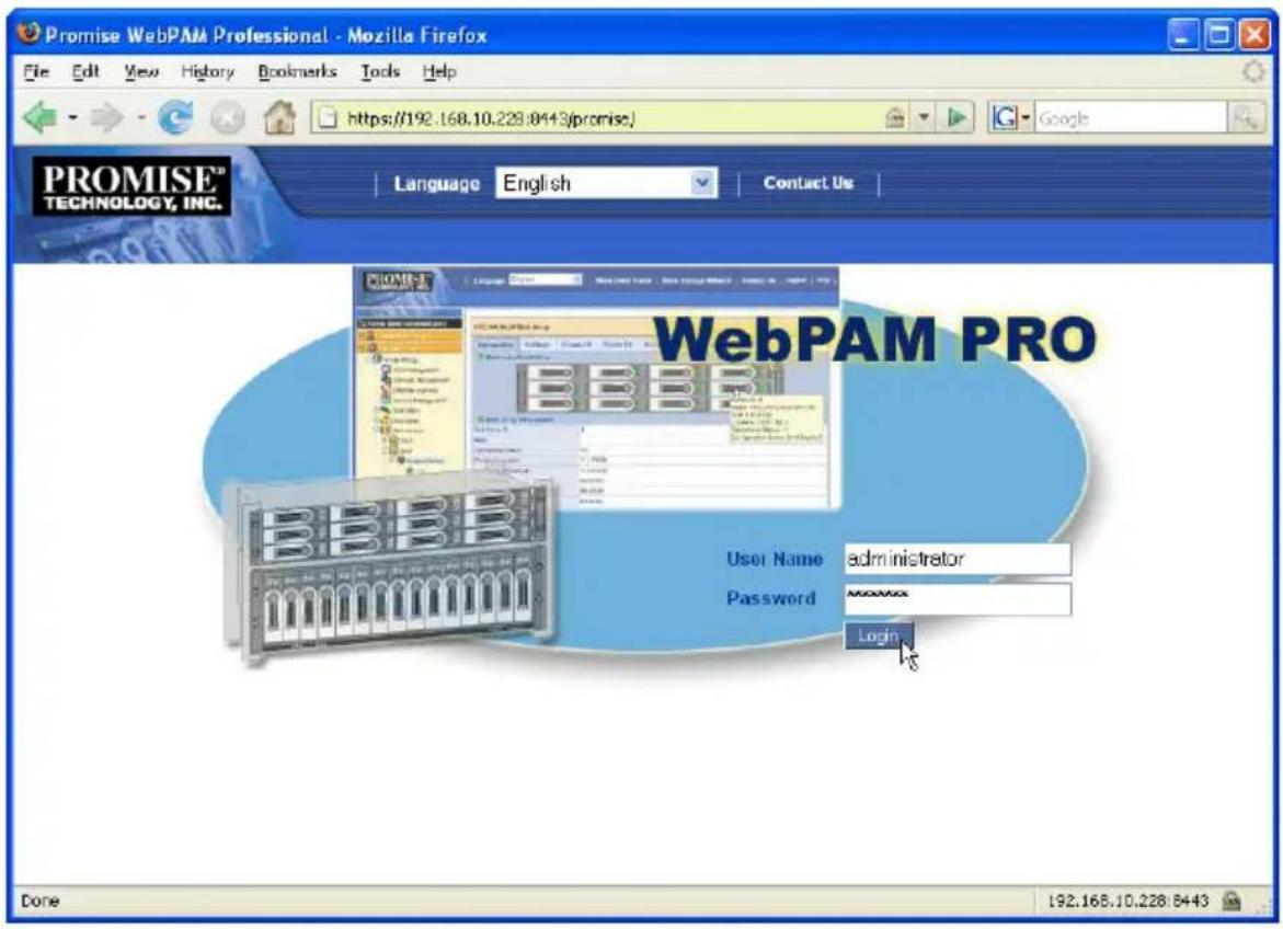
Accessing the Interface
WebPAM PRO is browser-based RAID management software with a graphic user interface. Basic user interface components and functions include:
• Using the Header (page 113)
• Using Tree View (page 113)
• Using Management View (page 114)
- Choosing a Display Language (page 115)
• Viewing the Event Frame (page 115)
- Saving the Event Frame (page 116)
- Deleting the Event Frame (page 116)
• Viewing the Storage Network (page 116)
- Logging out of WebPAM PRO (page 117)
Figure 2. WebPAM PRO interface
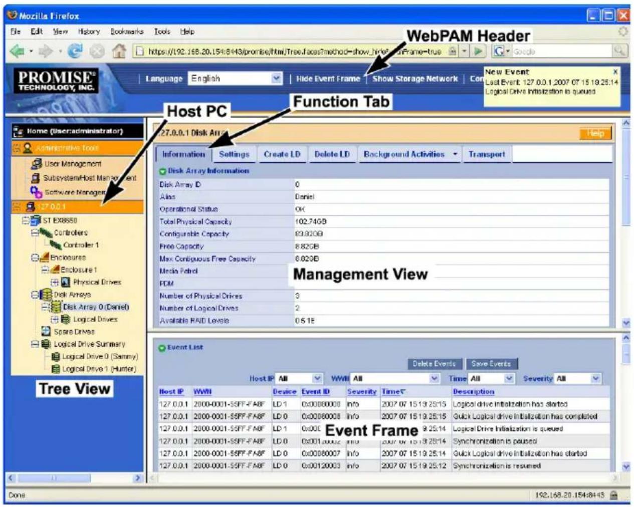
There are four major parts to the WebPAM PRO interface:
- Header (see page 113)
- Tree View (see page 113)
- Management View (see page 114)
• Event Frame (see page 115)
Using the Header
The Header contains the following items:
- Language – To choose a display language, see “Choosing a Display Language” on page 115.
- Show/Hide Event Frame – To view the Event Frame, see “Viewing the Event Frame” on page 115.
- Show/Hide Storage Network – To view the Storage Network, see “Viewing the Storage Network” on page 116.
- Contact Us – Click here for Promise Technology contact information. Or see “Contacting Technical Support” on page 277.
- Logout – To logout, see “Logging out of WebPAM PRO” on page 117.
Using Tree View
Tree View enables you to navigate around all components of the Host PC (where the SuperTrak controller card is installed), software management, RAID controller, enclosure, physical drives, disk arrays, logical drives, and spare drives. The figure below shows the components of Tree View.
Figure 3. WebPAM PRO Tree View
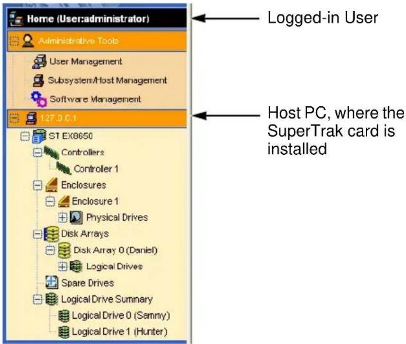
The Administrative Tools section is different for the Administrator and Super Users than for other users. The remainder of the Tree is the same for all users.
Management View displays information according to the item you choose in Tree View.
Using Management View
Management View—also referred to Management View—provides the actual user interface with the SuperTrak EX Controller card, including creation, maintenance, deletion, and monitoring of disk arrays and logical drives.
Function Tabs control specific actions and processes. This View changes depending on which item you choose in Tree View and which tab you choose in the Management View itself.
Click the Help button to the right of the tabs in Management View to access online help for the function that is currently displayed.
Choosing a Display Language
WebPAM PRO displays in the following languages:
- English
• l t a l i a n - Simplified Chinese
- Japanese
- Traditional Chinese
- Korean
• F r e n c • Spanish
• G e r m a • Russian
To change the display language:
- Click the Language dropdown menu in the Header.
- Highlight the language you prefer.
WebPAM PRO displays in the chosen language.
Viewing the Event Frame
To view the Event Frame, click Show Event Frame in the Header.
To hide the Event Frame, click Hide Event Frame in the Header.
The Event Frame reports all events and stores them in the WebPAM PRO folder on the hard disk drive of the Host PC.
In the event frame, events are listed and sorted by:
- Host IP – The IP address of the Host PC or subsystem where the event happened
- WWN – World Wide Number of the Host PC or subsystem where the event happened
• Device – Disk array, logical drive, physical drive, controller, battery, etc.
• Event ID – The hexadecimal number that identifies the specific type of event -
Severity – See below:
-
Information – Information only, no action is required
- Warning – User can decide whether or not action is required
- Minor – Action is needed but the condition is not serious at this time
• Major – Action is needed now - Critical – Action is needed now and the implications of the condition are serious
- Fatal – Non-Recoverable error or failure has occurred
- Time – Time and date of the occurrence
- Description – A brief description of the event
You can also view events by clicking the Subsystems icon in Tree View, then clicking the Event tab in Management View.
Saving the Event Frame
This function saves a copy of the events from the Event Frame as a text file on the Host PC's hard drive.
To save the event log:
- In the Header, click Show Event Frame.
- In the Event Frame, click the Save Events button.
- In the File Download dialog box, click the Save button.
- In the Save dialog box, name the file, navigate to the folder where you want to save the log file, and click the Save button.
The event log is saved as a text file on the Host PC's hard drive.
Deleting the Event Frame
This function deletes the events from the Event Frame and from the WebPAM PRO database. Deleting the events from this point does not affect events physically stored in the HBA's or Subsystem's RAM or NVRAM.
This function has no effect upon events reported under the SubsystemIcon Events tab. See “Viewing the Runtime Event Log” on page 134 and “Viewing the NVRAM Event Log” on page 135.
To clear the event log:
- In the Header, click Show Event Frame.
- In the Event Frame, click the Delete Events button.
- In the Confirmation dialog box, type confirm and click the OK button.
Viewing the Storage Network
The Storage Network consists of all the subsystems and host PCs currently accessible on your network. Use this function to identify the subsystem or host PC you want to add.
Subsystems and host PCs already added to WebPAM PRO have a + icon beside them in Tree View.
Figure 4. The Storage Network appears in Tree View
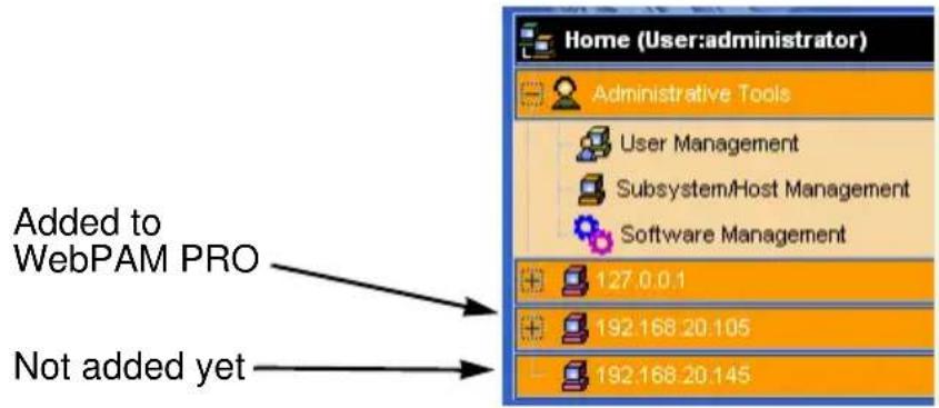
To view the Storage Network, click Show Storage Network in the Header. All networked systems will appear in Tree View.
To hide the Storage Network, click Hide Storage Network in the Header. Only the networked systems you have added appear in Tree View.
See "Adding a Subsystem or Host" on page 122.
Logging out of WebPAM PRO
There are two ways to log out of WebPAM PRO:
- Close your browser window
• C l i c k
Logout in the WebPAM PRO Header
Figure 5. Clicking "Logout" in the Header)

Clicking Logout brings you back to the Login Screen. After logging out, you must enter your user name and password in order to log in again.
Managing Users
User Management deals with user accounts. Functions include:
- Viewing User Information (page 118)
- Making User Settings (page 118)
- Making Your Own User Settings (page 119)
- Changing a User's Password (page 119)
- Changing Your Own Password (page 119)
- Creating a User (page 120)
- Deleting a User (page 120)
Viewing User Information
The view a list of users, their status, access privileges, display name, and email address:
- Click the Administrative Tools icon.
- Click the User Management icon.
The Information tab appears in Management View.
Making User Settings
To change settings of other users:
- Log into WebPAM PRO as the Administrator or a Super User.
- Click the Administrative Tools icon.
- Click the User Management icon.
- Click the Information tab in Management View.
-
In the list of users, click the link of the user whose settings you want to change.
The Settings screen for the chosen user displays. -
Enter or change the settings for this user.
-
Enable/disable this user
- Display name
-
Privilege. See "List of User Privileges" on page 120
-
Click the Submit button.
The Administrator or Super User can change another user's password. See "Changing a User's Password" on page 119 for more information.
You can also set user privilege under Subsystem/Host Management. See "Setting User Privilege" on page 124 and "Setting User Rights" on page 130.
Making Your Own User Settings
To change your own user settings:
- Log into WebPAM PRO under your own user name.
- Click the Administrative Tools icon.
- Click the User Management icon.
- Click the Settings tab in Management View.
- Enter or change the display name or mail address.
- Click the Submit button.
Changing a User's Password
To change a user's password:
- Log into WebPAM PRO as the Administrator or a Super User.
- Click the Administrative Tools icon.
- Click the User Management icon.
-
In the list of users, click the link of the user whose settings you want to change.
The Settings screen for the chosen user displays. -
Click the Password tab in Management View.
- Enter the new password in the New Password field.
- Enter the new password in the Retype Password field.
- Click the Submit button.
Changing Your Own Password
To set or change your own password:
- Log into WebPAM PRO under your own user name.
- Click the Administrative Tools icon.
- Click the User Management icon.
- Click the Password tab in Management View.
-
Enter the current password in the Old Password field. If you do not have a password, leave this field blank.
-
Enter the new password in the New Password field.
-
Enter the new password in the Retype Password field.
-
Click the Submit button.
Creating a User
To create a user:
- Log into WebPAM PRO as the Administrator or a Super User.
- Click the Administrative Tools icon.
- Click the User Management icon.
- Click the Create tab in Management View.
- Enter a user name in the User Name field.
- Enter a password for this user in the New Password and Retype Password fields.
A password is optional. If you do not assign password, tell this user to leave the password field blank when he/she logs into to WebPAM PRO. Users can set their own passwords, see “Changing Your Own Password” on page 119.
- Check the Enabled box to enable this user on this subsystem.
- Enter a display name in the Display Name field.
A display name is optional but recommended.
- Choose a privilege level from the Privilege dropdown menu.
For definitions of each privilege level, see the List of User Privileges below.
- Click the Submit button.
List of User Privileges
- View – Allows the user to see all status and settings but not to make any changes
- Maintenance – Allows the user to perform maintenance tasks including Rebuilding, PDM, Media Patrol, and Redundancy Check.
- Power – Allows the user to create (but not delete) disk arrays and logical drives, change RAID levels, change stripe size; change settings of components such as disk arrays, logical drives, physical drives, and the controller.
- Super – Allows the user full access to all functions including create and delete users and changing the settings of other users, and delete disk arrays and logical drives. The default “administrator” account is a Super User.
Deleting a User
There will always be at least one Super User account. You cannot delete the user account you used to log in. To delete a user:
- Log into WebPAM PRO as the Administrator or a Super User.
-
Click the Administrative Tools icon.
-
Click the User Management icon.
- Click the Delete tab in Management View.
- Check the box to the left of the user you want to delete.
- Click the Submit button.
- Click OK in the confirmation box.
Working with Subsystem/Host Management
Subsystem/Host Management includes the following functions:
- Viewing Subsystem/Host Information (page 122)
- Adding a Subsystem or Host (page 122)
- Deleting a Subsystem or Host (page 123)
- Setting User Privilege (page 124)
- Updating the Firmware on Multiple Systems (page 124)
Viewing Subsystem/Host Information
To view the Subsystem/Host List:
- Click the Administrative Tools icon in Tree View.
- Click the Subsystem/Host Management icon.
In the Information tab, the following information appears:
- Subsystem/Host IP address
- Management Port IP address
- Model of the RAID controller
- Alias of the RAID controller
- Firmware Version of the RAID controller
• Interface of the RAID controller
• World Wide Number of the RAID controller
- Health – A green checkmark means OK. A red X indicates a problem
If a red X appears under Health, click the Health Information icon to display a breakdown showing the health of the controller, disk arrays, logical drives, spare drives, and physical drives.
Adding a Subsystem or Host
To add a subsystem/ or host PC to WebPAM PRO:
- Log into WebPAM PRO as the Administrator or a Super User.
- Click the Administrative Tools icon in Tree View.
- Click the Subsystem/Host Management icon.
-
Click the Add Subsystem/Host tab in Management View.
-
Do one of the following actions:
-
To create an in-band connection: Type the Host PC's IP address into the address field.
Choose this option for SuperTrak. Note that entries such as localhost or the Host PC's network name do not work for this function. -
To create an out-of-band connection: Type the Subsystem's management port IP address into the address field.
-
Click the Submit button.
The new Subsystem or Host PC is added to Tree View.
In-Band versus Out-of-Band
In-band connection
• The WebPAM PRO Agent is running on the Host PC or server.
• The WebPAM PRO Client/Server is running on any PC on the network.
- Management commands to a subsystem travel through the subsystem's data ports.
• Multiple subsystems can appear under the same Host PC or server.
Out-of-band connection
- The WebPAM PRO Agent is running on the subsystem.
- The WebPAM PRO Client/Server is running on the same Host PC on the network.
- Management commands to a subsystem travel through the subsystem's management port.
• Only one subsystem can appear under a Host PC or server.
Deleting a Subsystem or Host
When you delete a subsystem or host PC, you only remove it from WebPAM PRO's list of monitored systems. This action has no effect upon the disk arrays, logical drives, or data stored on the RAID.
To delete a subsystem or host PC:
- Log into WebPAM PRO as the Administrator or a Super User.
- Click the Administrative Tools icon in Tree View.
- Click the Subsystem/Host Management icon.
- Click the Delete Subsystem/Host tab in Management View.
- Check the box to the left of the subsystem or host PC you want to delete.
-
Click the Submit button.
-
In the confirmation box, type the word confirm in the field provided.
- Click the OK button.
Setting User Privilege
To set user privilege:
- Click the Administrative Tools icon in Tree View.
- Click the Subsystem/Host Management icon.
- Click the IP address link of the Subsystem or Host you want to access.
-
Beside the name of the user whose privilege you want to change, choose the privilege level from the Privilege dropdown menu.
For definitions of each privilege level, see “List of User Privileges” on page 120. -
Click the Submit button.
You can also set user privilege under User settings. See “Making User Settings” on page 118.
Updating the Firmware on Multiple Systems

Cautions
- Before you begin, backup any important or useful data.
- Do NOT power off your PC during the procedure.
Use this function to update the firmware and BIOS on SuperTrak controllers in multiple Host PCs at the same time.
You must first download the update file and save it to the Host PC. See "Downloading BIOS and Firmware File" on page 289.
Note that this function does not update the software driver. Install the software driver file following the procedure for your operating system. See “Chapter 3: Installing Drivers” on page 63.
You can also update the firmware on:
- An individual SuperTrak controller
• A VTrak JBOD enclosure
See "Updating the Firmware" on page 132.
To update the SuperTrak firmware on multiple Host PCs:
- Click the Administrative Tools icon in Tree View.
-
Click the Subsystem/Host Management icon.
-
In Management View, click the Multiple Firmware Update tab dropdown menu and choose Multiple HBA Firmware Update.
- From the Subsystem/Host List, check the box beside the Host PCs with the SuperTrak controllers you want to update.
- Choose the Download Flash File from Local File through HTTP option and click the Next button.
- Click the Browse button and navigate to the directory where you saved the update file, then click the update file, and click the Open button.
- Click the Start button.
When the Flash Image Status shows Flash image completed, the firmware and BIOS have been updated.
- Restart the Host PCs.
Managing Software Services
Software Services include the following functions:
- Viewing Service Status (page 126)
- Changing Web Server Settings (page 126)
- Restarting the Tomcat Server (page 127)
- Setting up Email Service (page 127)
- Setting up Extended SMTP (page 128)
- Setting Event Frame Refresh Time (page 128)
- Changing CIM Client Settings (page 129)
- Changing CIM Server Settings (page 129)
Viewing Service Status
There are two software services: Web Server and Email. There are no user settings. To view the status of the software services:
- Click the Administrative Tools icon in Tree View.
- Click the Software Management icon.
The service name, startup type, and current status appear under the Service tab.
Changing Web Server Settings
To change the Web Server settings:
- Click the Administrative Tools icon in Tree View.
- Click the Software Management icon.
- Click the Web Server tab in Management View.
- Do one of the following actions:
- For a regular connection:
In the HTTP Port field, type the HTTP port number.
The default is 8080.
- For a secure connection:
Check the Enable SSL box.
In the HTTPS Port field, type the HTTPS port number.
The default is 8443.
- In the Session Time Out field, enter a time value in minutes.
The range is 1 to 1440 minutes. 15 minutes is the default.
Session Time Out refers to the amount of time the connection remains active without any user interaction. After WebPAM PRO reaches the Time Out interval, you must log in again and begin a new session.
- Click the Submit button.
- In the confirmation box, type the word confirm in the field provided.
- Click the OK button.
Restarting the Tomcat Server
After you change the Web Server port number, you must restart the Tomcat server on the Host PC.
Windows
In the Start menu, choose Programs > WebPAM PRO > Server > Restart.
Linux
- Open a terminal window.
- Go to the server folder. cd /opt/Promise/WebPAMPRO/Server
- Run the restart command: sh restartPromiseWebPamPro.sh
The system returns: /etc/rc.d/init.d/ exists. Shutting down: tomcat OK Starting: tomcat OK (Or a similar message)
Setting up Email Service
To change the Email settings:
- Click the Administrative Tools icon in Tree View.
- Click the Software Management icon.
- Click the Email tab in Management View.
- Enter an Email sender address (example: RAIDmaster@mycompany.com) in the field provided.
- Enter an Email server IP address in the field provided.
- Enter an Email subject (example: VTrak Status) in the field provided.
- When you are done, click the Submit button.
Setting up Extended SMTP
To make Extended SMTP settings:
- Click the Administrative Tools icon in Tree View.
- Click the Software Management icon.
- Click the Email tab in Management View.
- Check the Enable ESMTP box to enable ESMTP.
Uncheck the box to disable ESMTP.
- Enter ESMTP user name in the field provided.
- Enter a ESMTP password in the field provided.
- When you are done, click the Submit button.
Sending A Test Email Message
Before you can send a test message, your email service must be set up as described in “Setting up Email Service” on page 127.
To send a test email message:
- Click the Administrative Tools icon in Tree View.
- Click the Software Management icon.
- Click the Email tab in Management View.
- Click the Test Email button.
A new window opens.
- Type the recipient's email address in the field provided.
- Click the Submit button.
WebPAM PRO sends a test email message to the address you specified.
Setting Event Frame Refresh Time
To set the refresh time for the Event Frame:
- Click the Administrative Tools icon in Tree View.
- Click the Software Management icon.
- Click the Refresh time tab.
- Choose a time interval from the Event Refresh Time dropdown menu. The choices are 15, 30, 60, and 300 seconds.
- Click the Submit button.
Changing CIM Client Settings
The CIM client is part of the WebPAM PRO Utility Server. The Utility Server can be installed on any PC on the network. Only one CIM client and Utility Server installation is required.
The CIM client works with CIM server. The CIM server is part of the WebPAMPRO Agent. The Agent must be installed on every host PC where the HBA RAID controller is installed to enable management over a network.
Under most conditions, there is no need to change CIM settings.
To change settings for the CIM client:
- Click the Administrative Tools icon in Tree View.
- Click the Software Management icon.
- Click the CIM Settings tab.
- Type the user name in the CIM User name field.
The default name is "cim".
- Type a password into the CIM User Password field.
The default password is "password".
- Click the Submit button.

Important
If you change CIM client settings, you must make matching CIM server settings on ALL Host PCs, otherwise WebPAM PRO will be unable to monitor them.
Be sure you change the CIM server settings on ALL of your Host PCs to match the CIM client settings.
Changing CIM Server Settings
To change settings for the CIM server:
-
On the Host PC, access the WebPAM PRO agent folder.
-
Windows – C:/Program Files/WebPAMPRO/Agent/bin
-
Linux – /opt/WebPAMPRO/Agent/bin
-
Open a command prompt, type cimuser --help and press Enter.
-
Follow the instructions on the screen.
Managing the Host
The Host is designated by its IP address:127.0.0.1. Host functions include:
• Viewing Host Information (page 130)
- Setting User Rights (page 130)
- Refreshing the WebPAM PRO Screen (page 130)
Viewing Host Information
To view Host information, click the 127.0.0.1 icon in Tree View. In the Information tab, the following information appears:
- Management Port IP address (refers to the Host PC)
- Model of the RAID controller
- Alias of the RAID controller
- Firmware Version of the RAID controller
• Interface of the RAID controller
• World Wide Number of the RAID controller
Setting User Rights
User rights is the same function as user privilege. To set user rights:
- Click the 127.0.0.1 icon in Tree View.
- Click the User Rights tab.
- Beside the name of the user whose privilege you want to change, choose the privilege level from the Privilege dropdown menu.
For definitions of each privilege level, see “List of User Privileges” on page 120. - Click the Submit button.
You can also set user privilege under User settings. See “Making User Settings” on page 118
Refreshing the WebPAM PRO Screen
Unlike clicking browser's refresh button, this function calls new information from the RAID controller's firmware to update the screen. To refresh the screen:
- Click the 127.0.0.1 icon in Tree View.
- Click the Refresh tab.
- Click the Submit button.
- Click the OK button in the confirmation box.
Managing the Subsystem
Subsystem functions include:
- Viewing Subsystem Information (page 131)
- Clearing Statistical Data (page 132)
- Setting an Alias for the Subsystem (page 132)
- Viewing the Runtime Event Log (page 134)
- Saving the Runtime Event Log (page 134)
- Clearing the Runtime Event Log (page 135)
- Viewing the NVRAM Event Log (page 135)
- Saving the NVRAM Event Log (page 136)
- Clearing the NVRAM Event Log (page 136)
- Updating the Firmware (page 132)
- Checking Subsystem Health (page 133)
- Viewing the NVRAM Event Log (page 135)
- Viewing Current Background Activities (page 136)
- Making Background Activity Settings (page 137)
- Running Background Activities (page 138)
- Running Media Patrol (page 138)
- Running PDM (page 138)
- Viewing Scheduled Activities (page 139)
- Scheduling an Activity (page 139)
- Deleting a Scheduled Activity (page 141)
- Viewing System Configuration (page 141)
Viewing Subsystem Information
To view information about a subsystem, click the Subsystem icon in Tree View. Management View displays the subsystem information.
To view information about the Host PC, users, controllers, schedules, activities, physical drives, disk arrays, and logical drives, see “Viewing System Configuration” on page 141.
Clearing Statistical Data
Use this function to clear the statistical data registers for the controller, physical drives, and logical drives.
To clear statistical data:
- In Tree View, click the Subsystem
- In Management View, click the Information tab.
- Click the Clear Statistics link.
- Click the Submit button.
- In the Confirmation dialog box, type confirm and click the OK button.

Setting an Alias for the Subsystem
An alias is optional. To set an alias for this subsystem or host:
- In Tree View, click the Subsystem
- In Management View, click the Settings tab.
- Enter a name into the Alias field.
Maximum of 48 characters. Use letters, numbers, one space between words, and underscore. - Click the Submit button.

Updating the Firmware

Cautions
- Before you begin, backup any important or useful data.
- Do NOT power off your PC during the procedure.
Use this function to update:
- Firmware and BIOS on a SuperTrak controller card
- Firmware on a VTrak JBOD enclosure
You must first download the update file and save it to the Host PC. See "Downloading BIOS and Firmware File" on page 289.
Note that this function does not update the software driver. Install the software driver file following the procedure for your operating system. See “Chapter 3: Installing Drivers” on page 63.
You can also update the firmware on the SuperTrak controllers in multiple Host PCs at the same time. See “Updating the Firmware on Multiple Systems” on page 124.
SuperTrak Controller Card
To upgrade the firmware on a SuperTrak Controller Card:
- In Tree View, click the Subsystem
- From the Firmware Update tab, choose Controller Firmware Update.
- Choose the Download Flash File from Local File through HTTP option and click the Next button.
- Click the Browse button.
- Navigate to the directory where you saved the update file, then click the update file, and click the Open button.
- Click the Submit button.
When the Flash Image Status shows Flash image completed, the firmware and BIOS have been updated. - Restart the Host PC.

VTrak JBOD Enclosure
To upgrade the firmware on an attached VTrak JBOD enclosure:
- In Tree View, click the Subsystem
- From the Firmware Update tab, choose JBOD Firmware Update.
- Click the Browse button.
- Navigate to the directory where you saved the update file, then click the update file, and click the Open button.
- Click the Submit button.
When the Flash Image Status shows Flash image completed, the firmware has been updated. - Shut down the Host PC.
- Power cycle the VTrak enclosures.
Turn OFF both power supply switches. Wait 30 seconds. Turn ON both power supply switches. Do this action for all attached VTrak enclosures. - Boot the Host PC.

Checking Subsystem Health
- In Tree View, click the Subsystem
- In Management View, click the Health tab.
The health or status of following items is displayed: - Controller
- Disk Array
- Logical Drive

- Spare Drive
- Physical Drive
If any item reports other than “OK” click that item in the Tree to investigate the cause of the problem.
Viewing the Runtime Event Log
Runtime Events lists information about all events recorded since the system was started. Runtime events are stored in RAM on the RAID controller. These events are cleared when you reboot your system.
To view runtime events:
- In Tree View, click the Subsystem
- From the dropdown menu on the Event tab, choose Runtime Events. The events are listed from newest at the top of the list to oldest at the bottom.

Severity Definitions
Each event is marked with a level of severity.
• Information – Information only, no action is required
- Warning – User can decide whether or not action is required
- Minor – Action is needed but the condition is not serious at this time
• Major – Action is needed now
- Critical – Action is needed now and the implications of the condition are serious
- Fatal – Non-Recoverable error or failure has occurred
Saving the Runtime Event Log
This function saves a copy of the runtime event log as a text file on the Host PC's hard drive.
To save the runtime event log:
- In Tree View, click the Subsystem
- From the dropdown menu on the Event tab, choose Runtime Events.
- At the bottom of the window, click the Save Event Log button.
- In the File Download dialog box, click the Save button.
- In the Save dialog box, name the file, navigate to the folder where you want to save the log file, and click the Save button.
A text file of the event log is saved to the Host PC's hard drive.

Clearing the Runtime Event Log
This function clears the events from the runtime event log screen and from the RAM on the RAID controller. This function has no effect upon events reported in the WebPAM PRO Event Frame. "Viewing the Event Frame" on page 115.
To clear the runtime event log:
- In Tree View, click the Subsystem icon.
- From the dropdown menu on the Event tab, choose Runtime Events.
- At the bottom of the window, click the Clear Event Log button.
- In the Confirmation dialog box, type confirm and click the OK button. All events are cleared from the screen and the RAID controller's RAM.
Viewing the NVRAM Event Log
NVRAM Events lists information about the most recent important or critical events. NVRAM events are stored in non-volatile memory on the RAID controller. This information persists even if you reboot your system.
To view runtime events:
- In Tree View, click the Subsystem icon.
- From the dropdown menu on the Event tab, choose NVRAM Events. The events are listed from newest at the top of the list to oldest at the bottom.
Severity Definitions
Each event is marked with a level of severity.
- Information – Information only, no action is required
- Warning – User can decide whether or not action is required
- Minor – Action is needed but the condition is not serious at this time
• Major – Action is needed now - Critical – Action is needed now and the implications of the condition are serious
- Fatal – Non-Recoverable error or failure has occurred
Saving the NVRAM Event Log
This function saves a copy of the NVRAM event log as a text file on the Host PC's hard drive.
To save the NVRAM event log:
- In Tree View, click the Subsystem
- From the dropdown menu on the Event tab, choose NVRAM Events.
- At the bottom of the window, click the Save Event Log button.
- In the File Download dialog box, click the Save button.
- In the Save dialog box, name the file, navigate to the folder where you want to save the log file, and click the Save button.
A text file of the event log is saved to the Host PC's hard drive.

Clearing the NVRAM Event Log
This function clears the events from the NVRAM event log screen and from the NVRAM on the RAID controller. This function has no effect upon events reported in the WebPAM PRO Event Frame. "Viewing the Event Frame" on page 115.
To clear the NVRAM event log:
- In Tree View, click the Subsystem
- From the dropdown menu on the Event tab, choose NVRAM Events.
- At the bottom of the window, click the Clear Event Log button.

- In the Confirmation dialog box, type confirm and click the OK button. All events are cleared from the screen and the RAID controller's non-volatile RAM.
Viewing Current Background Activities
To view the current background activities:
- Click the Subsystem icon in Tree View.
- Click the Background Activities tab in Management View.
A list of current background activities appears, including: - Rebuild
- PDM – Predictive Data Migration
- Synchronization
- Redundancy Check
- M i g r a t i o n
-
Transition
-
Initialization
- Media Patrol
Making Background Activity Settings
To make settings for background activities:
- In Tree View, click the Subsystem
- From the dropdown menu on the Background Activities tab, choose Settings.
- Click the dropdown menu to choose a priority of Low, Medium, or High for the following functions:
- Rebuild – Rebuilds the data from a failed drive in a disk array
- Synchronization – Checks the data integrity on disk arrays
- Initialization – Sets all data bits in the logical drive to zero
- Redundancy Check – Checks, reports and can correct data inconsistencies in logical drives
- Migration – Change RAID level or add physical dries to disk arrays
- PDM – Looks for bad blocks the physical drives of disk arrays
• Transition – Returns a revertible spare drive to spare status
The rates are defined as follows: - Low – Fewer resources to activity, more to data read/write.
• Medium – Balance of resources to activity and data read/write. - High – More resources to activity, fewer to data read/write.

-
Highlight the following PDM trigger settings and type a value into the corresponding field:
-
Reassigned Block Threshold – 1 to 512 blocks
-
Error Block Threshold – 1 to 1024 blocks
-
Check to enable or uncheck to disable the following functions:
• Media Patrol – Checks the magnetic media on physical drives
- Auto Rebuild – This function applies to conditions when an array goes Critical but no spare drive is present. When enabled, the disk array will begin to rebuild as soon as you replace the failed physical drive with an unconfigured physical drive of equal or greater size.
For conditions when an array goes Critical and a spare drive of adequate size is present, a rebuild begins automatically. This is a separate function and always enabled.
- Click the Submit button to save your settings.
Running Background Activities
To run a background activity from the Background Activities tab:
- In Tree View, click the Subsystem

- From the dropdown menu on the Background Activities tab, choose one of the following activities:
• Media Patrol – See “Running Media Patrol” on page 138
- Rebuild – See “Rebuilding a Disk Array” on page 168
- PDM – See “Running PDM” on page 138
• Transition – See “Transitioning a Disk Array” on page 170
- Initialization – See “Initializing a Logical Drive” on page 175
- Redundancy Check – See “Running Redundancy Check” on page 176
-
In the next screen, make the choices as requested.
-
Click the Start button.
Running Media Patrol
Media Patrol checks the magnetic media on physical drives. When it finds the specified number of bad blocks, it will trigger PDM. See “Making Background Activity Settings” on page 137 and “Running PDM” on page 138.
You can schedule Media Patrol to run automatically, see "Scheduling an Activity" on page 139.
To run Media Patrol:
- In Tree View, click the Subsystem

- From the dropdown menu on the Media Patrol.
Background Activities tab, choose Start
- In the next screen, click the Start button.
Running PDM
Predictive Data Migration (PDM) migrates data from the suspect physical drive to a spare disk drive, similar to Rebuilding. But unlike Rebuilding, PDM acts before the disk drive fails and your Logical Drive goes Critical.
You an also run PDM on a specific disk array, see “Running PDM on a Disk Array” on page 169.
The target physical drive must be the same media type, HDD or SDD, as the other physical drives in the disk array.
Also see "Predictive Data Migration (PDM)" on page 255.
To run PDM:
- In Tree View, click the Subsystem icon.
- From the dropdown menu on the Background Activities tab, choose Start PDM.
- In the next screen, choose the Source and Target physical drives.
The suspect physical drive is the Source.
The replacement physical drive is the Target. - Click the Start button.
Viewing Scheduled Activities
To view scheduled activities for this subsystem:
-
Click the Subsystem icon Tree View.
-
Click the Scheduler tab in Management View.
Scheduling an Activity
To set a scheduled activity for this subsystem:
- Click the Subsystem icon Tree View.
- From the dropdown menu on the Scheduler tab, choose Add BGA Scheduler.
- Click the option button of the activity you want:
• Media Patrol. See “Running Media Patrol” on page 138 - Redundancy Check. See "Running Redundancy Check" on page 176
-
Spare Check. See "Running Spare Check" on page 181
-
In the Scheduler dialog box, check the Enable This Schedule box.
-
Click the option button for the Recurrence Pattern you want:
| • | D | a | i | l | y | ||
| • | W | e | e | k | l | y | |
| • | M | o | n | t | h | l | y |
-
Click the Next button.
-
For a DAILY recurrence pattern, make the following setting:
-
Choose a Start Time for the activity, based on a 24-hour clock, from the dropdown menus.
- Type the number of days between activities, from 1 to 255, into the Every days field.
For a WEEKLY recurrence pattern, make the following settings:
- Choose a Start Time for the activity, based on a 24-hour clock, from the dropdown menus.
- Type the number of weeks between activities, from 1 to 52, into the Every weeks field.
- Check the boxes for the days of the week you want the activity to run. You can choose from 1 to 7 days.
For a MONTHLY recurrence pattern, make the following settings:
- Choose a Start Time for the activity, based on a 24-hour clock, from the dropdown menus.
- Choose the day of the month:
- Choose a day of the month, 1 to 31, from the dropdown menu. See the Note below.
- Choose a day of the month, first to last, and day of the week, from the dropdown menus.
- Check the boxes for the months of the year you want the activity to run. You can choose from 1 to 12 months.
- Choose a starting date in the Start From dropdown menus.
The default is today's date.
-
Choose an End On option:
-
No end date (recommended).
- End After the specified number of activities. Type the number of activities, from 1 to 255, into the field provided.
-
Until a specified date. Choose an end date from the dropdown menus. The default is today's date.
-
For Redundancy Check only:
-
Choose the Auto Fix option. This feature attempts to repair the problem when it finds an error.
- Choose the Pause on Error option. This feature stops the process when it finds an error
-
Check the boxes beside the logical drives (all except RAID 0) to which this activity will apply.
Note: Each logical drive can have only one scheduled Redundancy Check. -
Click the Submit button.

Note
For monthly schedules, if you choose a higher number than a month has days, the activity will occur in the following month. For example, say you choose day 31. But there are only 30 days in the month of June. Therefore, the June activity will happen on July 1. The next activity will happen on July 31.
Deleting a Scheduled Activity
To delete a scheduled activity for this subsystem:
- Click the Subsystem icon Tree View.
- From the dropdown menu on the Scheduler tab, choose Delete Schedules.
- Check the box to the left of the schedule you want to delete.
- Click the Submit button.
Viewing System Configuration
To view the configuration of your complete system:
- Click the Subsystem icon Tree View.
- Click the Configuration tab in Management View.
The following information is displayed:
- Host Information – WebPAM PRO version, host name and IP address, OS version, and JVM version
- User List – User name, status, and display name
- Controllers Summary – Alias, model, and operational status
- Scheduled Activities List – Type, recurrence, start time, and operational status
• Enclosures Summary – ID, type, operational status, and description - Physical Drive List – Device number, model, type, capacity, location, operational status, and configuration
- Disk Array List – ID, alias, operational status, configurable capacity, and free capacity
- Logical Drive List – Device number, alias, RAID level, capacity, ID, stripe size, sector size, and operational status
- Spare Drive List – ID, operational status, physical drive ID, capacity, revertibility, type (global or dedicated), and dedicated to array
Managing the Controller
The RAID controller is the heart of the RAID storage system. Management of Controllers includes the following functions:
• Viewing Controllers Information (page 142)
• Viewing Controller Information (page 142)
• Viewing Controller Statistics (page 144)
- Making Controller Settings (page 144)
- Clearing an Orphan Watermark (page 145)
• Viewing Battery Information (page 145)
• Silencing the Buzzer (page 146)
- Making Buzzer Settings (page 146)
- Testing the Buzzer (page 146)
• Viewing Buzzer Information (page 147)
Viewing Controllers Information
Controllers information refers to a brief summary about the controller. To view Controller information:
- Click the Subsystem icon in Tree View.
- Click the Controllers icon.
The controllers information appears under the Information tab in Management View. Controllers information includes:
- Controller ID
- Alias, if assigned
- Model of the RAID controller
- Status of the RAID controller – OK means normal
Viewing Controller Information
Controller information refers to detailed information about the controller. To view Controller information:
- Click the Subsystem icon in Tree View.
- Click the Controllers icon.
- Click the Controller icon.
The controller information appears under the Information tab in Management View. Controller information includes:
- Controller ID (1 or 2)
- Alias, if assigned*
- Vendor
- Model
- Operational Status
- Power On Time
- Cache Usage (percent)
- Dirty Cache Usage (percent) – Refers to data in the cache that is not yet saved to a physical drive
- Part number
- Serial number
• Hardware revision number
- WWN – World Wide Number of the controller
- Manufacturing Date
• SCSI protocols supported
- Host Driver Version
• B I O S V e r s i o n
- Single Image Version
- Single Image Build Date
- The Host driver is installed and updated through your operating system. You can update the other items automatically. See “Updating the Firmware” on page 132.
- Advanced controller information includes:
- Memory Type – Controller's data cache.
- Memory Size
- Flash Type – Stores firmware, software and user configurations.
- Flash Size
- NVRAM Type – Stores parameters, settings and tables.
- NVRAM Size
- Preferred Cache Line Size
- Cache Line Size
• C o e r c i o n *
- Coercion Method*
- SMART* – Self-Monitoring, Analysis and Reporting System for physical drives
Controller information, continued:
- SMART Polling Interval*
- Write Back Cache Flush Interval*
- Write Through Mode
• Enclosure Polling interval* - Adaptive Writeback Cache*
Items marked with an asterisk (*) are user adjustable. See “Making Controller Settings” on page 144.
Viewing Controller Statistics
To view controller statistics:
- Click the Subsystem icon in Tree View.
- Click the Controllers icon.
- Click the Controller icon.
- From the dropdown menu on the Information tab, choose Statistics.
Making Controller Settings
To make Controller settings:
- Click the Subsystem icon in Tree View.
- Click the Controllers icon.
- Click the Controller icon.
- Click the Settings tab in Management View.
- Make the following settings as needed:
- Optional. Enter a name into the Alias field.
Maximum of 48 characters. Use letters, numbers, one space between words, and underscore. An alias is not required.
- Check the SMART Log box to enable the Self-Monitoring, Analysis, and Reporting System (SMART).
- Enter a polling interval (1 to 1440 minutes) in SMART Polling Interval field.
- Check the Coercion Enabled box to enable disk drive capacity coercion.
- Choose a coercion method from the Coercion Method dropdown menu.
The choices are:
• G B T r u n c a t e
- 10GBTruncate
- GRPRounding
- TableRounding
For more information, see "Capacity Coercion" on page 246.
- Enter a time interval (1 to 12 seconds) in the Write Back Cache Flush Interval field.
- Enter a time interval (15 to 255 seconds) in the Enclosure Polling Interval field.
This is the time interval in which the controller polls all of the components in the enclosure.
- Check the box to enable Adaptive Writeback Cache
- Check the box to enable Forced Read Ahead Cache
For more information, see "Choosing Cache Policy" on page 245.
- Click the Submit button.
The changes take effect immediately.
Clearing an Orphan Watermark
An Orphan Watermark condition is the result of a disk drive failure during an NVRAM RAID level migration on a disk array. The Clear tab remains grayed out unless this condition is present.
To clear an orphan watermark:
- Click the Subsystem icon in Tree View.
- Click the Controllers icon.
- Click the Controller icon.
- Click the Clear tab in Management View.
- Click the Submit button.
The change takes effect immediately.
Viewing Battery Information
The RAID controller's cache backup battery protects data in the cache for up to 72 hours in the event of a power failure.
To view battery information:
- Click the Subsystem icon in Tree View.
- Click the Controllers icon.
- Click the Controller icon.
- Click the Battery tab in Management View.
In normal operation, the operational status of the battery shows Fully Charged with a Reserve Capacity of 100%. If the battery is constantly recharging, its
reserve capacity drops significantly, or the battery remains discharged, replace the battery. Also see “Viewing Enclosure Information” on page 148.
Silencing the Buzzer
To silence the buzzer for the current event:
- Click the Subsystem icon in Tree View.
- Click the Controllers icon.
- Click the Controller icon.
- Click the Buzzer tab in Management View.
- Click the Mute button.
The buzzer goes silent but will sound again for future events.
Making Buzzer Settings
To make buzzer settings:
- Click the Subsystem icon in Tree View.
- Click the Controllers icon.
- Click the Controller icon.
- From the dropdown menu on the Buzzer tab, choose Settings.
- Check the Enable Buzzer box to enable the buzzer.
Uncheck the box to disable the buzzer.
- Click the Submit button
The changes take effect immediately.
Testing the Buzzer
You must enable the buzzer before you can test it. See "Making Buzzer Settings," above.
To test the buzzer:
- Click the Subsystem icon in Tree View.
- Click the Controllers icon.
- Click the Controller icon.
- Click the Buzzer tab in Management View.
- Click the Sound button.
The buzzer sounds a continuous tone.
- Click the Mute button.
The buzzer goes silent but remains enabled.
Viewing Buzzer Information
This function refers to the buzzer on the SuperTrak RAID controller card.
To view buzzer information:
- Click the Subsystem icon in Tree View.
- Click the Controllers icon.
- Click the Controller icon.
- Click the Buzzer tab in Management View.
Managing Enclosures
This function of WebPAM PRO does not apply to the SuperTrak RAID controller card installed in a Host PC, except for one item:
- Viewing Enclosure Information (page 148)
Viewing Enclosure Information
Enclosure information includes:
- Enclosures I D
- Enclosure Type – Virtual
- SEP Firmware Version
• Maximum number of Controllers, Physical Drive Slots, Fans, Blowers, Temperature Sensors, Power Supply Units, Batteries, and Voltage Sensors.
This information might be useful when contacting Technical Support.
To view Enclosure information:
- Click the Subsystem icon in Tree View.
- Click the Enclosures icon.
- Click the Enclosure icon.
The Enclosure information appears on the Information tab.
See the following topics:
- "SAS Connections and ID Numbers" on page 15
- "Viewing Controller Information" on page 142
- "Viewing Battery Information" on page 145
- “Contacting Technical Support” on page 277.

Note
In addition to the SuperTrak EX Series, WebPAM PRO also supports Promise VTrak RAID Subsystems.
For more information about managing those products with WebPAM PRO, see the online help or refer to the Subsystem's Product Manual.
Managing Physical Drives
Managing Physical Drives deals with the physical disk drives under the SuperTrak RAID controller, including the following functions:
- Viewing a List of Physical Drives (page 149)
- Locating a Physical Drive (page 149)
- Making Global Physical Drive Settings (page 150)
- Viewing Physical Drive Information (page 151)
• Viewing Physical Drive Statistics (page 151) - Making Physical Drive Settings (page 152)
- Clearing Stale and PFA Conditions (page 152)
• Viewing the SMART Log (page 153) - Viewing Advanced SMART Log Information (page 154)
- Saving Advanced SMART Log Information (page 155)
- Making SMART Log Settings (page 155)
Viewing a List of Physical Drives
To view a list of physical drives in this enclosure:
- Click the Subsystem icon in Tree View.
- Click the Enclosures icon.
- Click the Enclosure icon.
- Click the Physical Drives icon.
The list of physical drives appears in Management View.
Click the PD link to view a specific physical drive. See “Viewing Physical Drive Information” on page 151.
Note that Enclosure and Slot numbers are assigned by the controller and do not necessarily correspond to the actual physical locations of the disk drives, especially when the disk drives are installed in an enclosure not designed by Promise.
Also see “SAS Connections and ID Numbers” on page 15.
Locating a Physical Drive
Virtual or Third Party Enclosures
Support for this feature depends on how your system or enclosure was set up. Direct-connect systems with individual LED connections and SGPIO enclosures support individual physical drive LEDs. Other systems or enclosures might or
might not support them. See “Appendix D: LED Backplane Connections” on page 295.
To locate a physical drive in the enclosure, click the Locate PDx button. The LED for the carrier holding the physical drive will blink for one minute.
Promise Enclosures
To locate a physical drive in the VTrak JBOD enclosure, click the Locate PDx button. The disk status LED will blink for one minute to identify the carrier holding the physical drive.
Figure 6. VTrak drive carrier LEDs
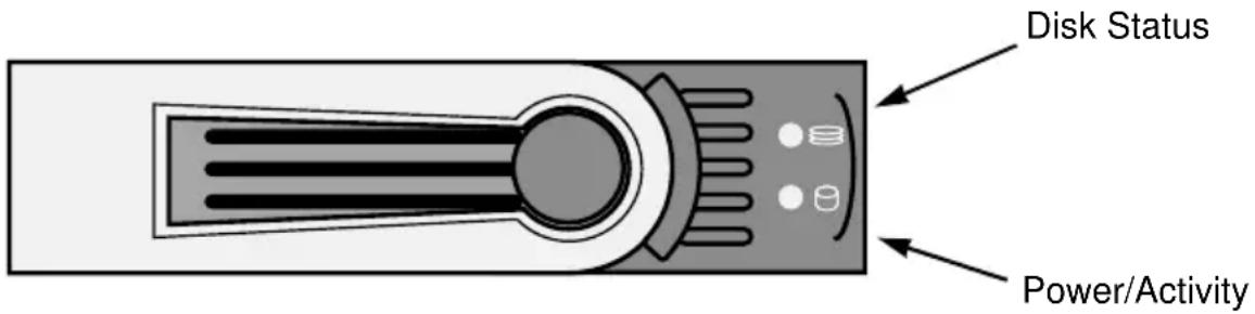
Making Global Physical Drive Settings
Global settings apply to all of the physical disk drives installed under the SuperTrak controller. The functions include:
| SATA Drives SAS Drives | |
| Enable Write CacheEnable Read Look Ahead CacheEnable Command Queuing | Enable Write CacheEnable Read Look Ahead CacheEnable Read Cache |
To make global physical drive settings:
- Click the Subsystem icon in Tree View.
- Click the Enclosures icon.
- Click the Enclosure icon.
- Click the Physical Drives icon.
- Click the Global Settings tab in Management View.
- Check the features you want to enable.
Uncheck any features you want to disable.
- Click the Submit button.
The changes take effect immediately.
The functions you enable here depend on whether the physical drives support those functions. See “Viewing Physical Drive Information” on page 151 to determine which functions a particular drive supports.
Viewing Physical Drive Information
To view physical drive information:
- Click the Subsystem icon in Tree View.
- Click the Enclosures icon.
- Click the Enclosure icon.
- Click the Physical Drives icon.
- Click a Physical Drive icon.
Useful information provided here includes:
- Operational Status – OK is normal. Can also show Rebuilding, Forced Online, Forced Offline, Transition Running, PDM Running, Media Patrol Running, Stale, PFA, Offline or Dead.
- Configuration Status – The array to which the drive is assigned or its spare designation, including Unconfigured, Stale, PFA, Global Spare, Dedicated Spare, Revertible Global Spare, Revertible Dedicated Spare.
Adjustable Items
- Write Cache – Enabled or disabled as chosen on the Physical Drives Settings tab.
- Read Look Ahead (Cache) – Enabled or disabled as chosen on the Physical Drives Settings tab.
- Command Queuing – SATA only. Enabled or disabled.
See "Making Global Physical Drive Settings" on page 150.
Viewing Physical Drive Statistics
To view physical drive statistics:
- Click the Subsystem icon in Tree View.
- Click the Enclosures icon.
- Click the Enclosure icon.
- Click the Physical Drives icon.
- Click a Physical Drive icon.
- From the dropdown menu on the Information tab, choose Statistics.
Making Physical Drive Settings
The only individual physical drive setting is an alias. An alias is optional. To set an alias for a physical drive:
- Click the Subsystem icon in Tree View.
- Click the Enclosures icon.
- Click the Enclosure icon.
- Click the Physical Drives icon.
- Click a Physical Drive icon.
- Click the Settings tab in Management View.
- Type an alias into the Physical Drive Alias field.
Maximum of 32 characters. Use letters, numbers, one space between words, and underscore.
- Click the Submit button.
Clearing Stale and PFA Conditions
The Clear tab only appears when one or both conditions are present.
• Stale – The physical drive contains obsolete disk array information.
- PFA – The physical drive has errors resulting in a prediction of failure.
Be sure you have corrected the condition by a physical drive replacement, rebuild operation, etc., first. Then clear the condition.
To clear a Stale or PFA status from a physical drive:
- Click the Subsystem icon in Tree View.
- Click the Enclosures icon.
- Click the Enclosure icon.
- Click the Physical Drives icon.
- Click a Physical Drive icon.
- in Management View, click the Clear tab.
- Click the Submit button.

Note
If a physical drive has both a Stale and a PFA condition, click the Submit button once to clear the Stale condition, then click again to clear the PFA condition.
Viewing the SMART Log
To view the SMART Log for a physical drive:
- Click the Subsystem icon in Tree View.
- Click the Enclosures icon.
- Click the Enclosure icon.
- Click the Physical Drives icon.
- Click a Physical Drive icon.
- in Management View, click the SMART Log tab.
Basic SMART Log Information for SAS Drives:
- Physical Drive ID – Unique ID number of this drive in your VTrak or SuperTrak system.
- InProgress – Yes or No. Whether a SMART scan is currently in progress on this drive.
• SMART Support – Yes or No. Whether this drive supports SMART. - SMART Log Enabled – Yes or No. Whether SMART Logging is enabled on this drive.
• SMART Health Status – OK is normal. N/A means there was no scan. - Current Drive Temperature – The drive's current temperature.
- Drive Trip Temperature – Highest recommended operating temperature for this drive.
- Max Start Stop Count – Maximum number of times this drive should be powered up and down.
- Current Start Stop Count – Actual number of times this drive has been powered up and down.
• Manufactured Year – Calendar year the drive was manufactured. - Manufactured Week In Year – Week number out of 52 weeks in the year listed above.
Basic SMART Log Information for SATA Drives:
- Physical Drive ID – Unique ID number of this drive in your VTrak or SuperTrak system.
- InProgress – Yes or No. Whether a SMART scan is currently in progress on this drive.
• SMART Support – Yes or No. Whether this drive supports SMART. -
SMART Log Enabled – Yes or No. Whether SMART Logging is enabled on this drive.
• SMART Health Status – OK is normal. N/A means there was no scan. -
SCT Status Version – SCT status version number for this drive.
- SCT Version – SCT version number for this drive.
- SCT Support Level – SCT support level for this drive.
- Device State – 0 means active.
- Current Temperature – The drive's current temperature.
- Power Cycle Min Temperature – Lowest temperature the drive reached since the last power up.
- Power Cycle Max Temperature – Highest temperature the drive reached since the last power up.
- Lifetime Min Temperature – Lowest temperature the drive recorded during its service life.
- Lifetime Max Temperature – Highest temperature the drive recorded during its service life.
- Under Temperature Limit Count – Number of times SMART found the drive below recommended operating temperature.
• Over Temperature Limit Count – Number of times SMART found the drive above recommended operating temperature.
If SMART Logging is disabled, only the first four items in the list are displayed.
SCT stands for SMART Command Transport, a protocol that allows servers using nearline-ready drives to adapt error recovery timing to match the application.
Viewing Advanced SMART Log Information
To view SMART Log information:
- Click the Subsystem icon in Tree View.
- Click the Enclosures icon.
- Click the Enclosure icon.
- Click the Physical Drives icon.
- Click a Physical Drive icon.
- in Management View, click the SMART Log tab.
- Click the Save Advanced SMART Log button.
- Choose the Open with option.
- Choose a text editor from the dropdown menu.
- Click the OK button.
Advanced SMART Log information displays on your PC in the text editor. This information is different for SAS and SATA drives and varies among different drive models and manufacturers.
Saving Advanced SMART Log Information
To save SMART Log information as a text file:
- Click the Subsystem icon in Tree View.
- Click the Enclosures icon.
- Click the Enclosure icon.
- Click the Physical Drives icon.
- Click a Physical Drive icon.
- in Management View, click the SMART Log tab.
- Click the Save Advanced SMART Log button.
- Choose the Save File option.
- Click the OK button.
Advanced SMART Log information is saved as a text file on your PC's desktop.
Making SMART Log Settings
To enable or disable SMART Logging on an individual physical drive:
- Click the Subsystem icon in Tree View.
- Click the Enclosures icon.
- Click the Enclosure icon.
- Click the Physical Drives icon.
- Click a Physical Drive icon.
- From the dropdown menu on the SMART Log tab, choose Settings.
- Check the Enable SMART Log box to enable SMART Logging.
Uncheck the box to disable.
- Click the Submit button.
SMART Logging is enabled or disabled on this drive according to your setting.
Managing Disk Arrays
Disk Array Management includes the following functions:
- Viewing Disk Arrays (page 156)
- Locating a Disk Array (page 156)
- Creating a Disk Array (page 157)
- Deleting a Disk Array (page 163)
- Viewing Disk Array Information (page 163)
- Making Disk Array Settings (page 164)
- Creating a Logical Drive (page 165)
- Deleting a Logical Drive (page 166)
- Migrating a Disk Array (page 167)
- Rebuilding a Disk Array (page 168)
- Running PDM on a Disk Array (page 169)
• Transitioning a Disk Array (page 170)
• Preparing a Disk Array for Transport (page 171)
Viewing Disk Arrays
To view the disk arrays in this enclosure plus any expanded or cascaded enclosures:
- Click the Subsystem icon in Tree View.
- Click the Disk Arrays icon.
A list of disk arrays appears in Management View.
Click the DA link to view a specific disk array. See "Viewing Disk Array Information" on page 163.
Locating a Disk Array
Virtual or Third Party Enclosures
Support for this feature depends on how your system or enclosure was set up. Direct-connect systems with individual LED connections and SGPIO enclosures support individual physical drive LEDs. Other systems or enclosures might or might not support them. See “Appendix D: LED Backplane Connections” on page 295.
To locate a disk array in the enclosure, click the Locate DAx button. The LEDs for the carriers holding the physical drives used by the disk array will blink for one minute.
Promise Enclosures
To locate a disk array in a VTrak JBOD enclosure, click the Locate DAx button. The disk status LEDs will blink for one minute to identify the carriers holding the physical drives used by the disk array.
Figure 7. VTrak drive carrier LEDs
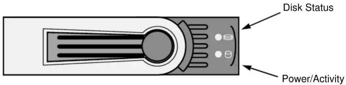
Creating a Disk Array
WebPAM PRO provides three methods of creating a disk array:
- Automatic – Creates a default disk array and logical drive based on unconfigured physical drives in the system. No user choices. If you have multiple enclosures, multiple disk array/logical drive sets are created. See “Creating a Disk Array – Automatic Configuration” on page 158.
- Express – You choose the RAID characteristics and type of application. Creates a disk array and logical drive(s) based on your input. See “Creating a Disk Array – Express Configuration” on page 159.
- Advanced – You specify all parameters for a new disk array. One logical drive will be made automatically when you create the disk array. If you specify less than the total available capacity, you can use the remaining space to create additional logical drives now or at a later time. See “Creating a Disk Array – Advanced Configuration” on page 161.
Creating a Disk Array – Automatic Configuration
The Disk Array – Automatic Configuration option enables you to create a new disk array following a default set of parameters. One logical drive will be made automatically when you create the disk array.
If you have multiple enclosures, a separate disk array and logical drive set is created for each enclosure.
If you have both Hard Disk Drives (HDD) and Solid State Drives (SSD), two separate disk array and logical drive sets are created. These two drive types cannot be mixed in the same disk array.
To create a Disk Array using the Automatic function:
- Click the Subsystem icon in Tree View.
- Click the Disk Arrays icon.
- From dropdown menu on the Create tab, choose Automatic.
The following parameters display:
- Disk Arrays – The number of physical drives in the disk array, their slot numbers, configurable capacity, and the number of logical drives to be created
- Logical Drives – The ID number of the logical drive(s), their RAID level, capacity, and stripe size
-
Spare Drives – The physical drive slot number of the dedicated hot spare assigned to this disk array. A hot spare drive is created for all RAID levels except RAID 0, when five or more unconfigured physical drives are available
-
If you accept these parameters, click the Submit button.
The new disk array appears in the Disk Array List the Information tab.
If you do NOT accept these parameters, use the Advanced option to create your disk array.
Creating a Disk Array – Express Configuration
The Disk Array – Express Configuration option enables you to choose the parameters for a new disk array by specifying the characteristics you want. With this method, you can create multiple logical drives at the same time you create your disk array. However, all of the logical drives will be the same.
If you prefer to specific the parameters directly, use the Advanced option to create your disk array.
If you are uncertain about choosing parameters for your disk array, use the Automatic option.
If you have both Hard Disk Drives (HDD) and Solid State Drives (SSD), two separate disk arrays are created for your HDDs and for your SSDs. Each array will have the number of logical drives that you specified.
To create a new disk array:
- Click the Subsystem icon in Tree View.
- Click the Disk Arrays icon.
- From the dropdown menu on the Create tab, choose Express.
-
Check the boxes to choose any one or combination of:
-
Redundancy – The array will remain available if a physical drive fails
• Capacity – The greatest possible amount of data capacity - Performance – The highest possible read/write speed
- Mixing SATA/SAS Drive – Check this box if you want to use both SATA and SAS drives in the same disk array.
If the box is unchecked, and you have both SATA and SAS drives, different arrays will be created for each type of drive.
- In the Number of Logical Drives field, enter the number of logical drives you want to make from this disk array.
- From the Application Type menu, choose an application that best describes your intended use for this disk array:
- Video Stream
- Transaction Data
- Transaction Log
-
Other
-
Click the Update button.
Or check the Automatic Update box and updates will occur automatically.
The following parameters display:
- Disk Arrays – The number of physical drives in the disk array, their slot numbers, configurable capacity, and the number of logical drives to be created
- Logical Drives – The slot number of the logical drive(s), their RAID level, capacity, and stripe size
- Spare Drives – The physical drive slot number of the dedicated hot spare assigned to this disk array (all RAID levels except RAID 0), when five or more unconfigured physical drives are available
If you accept these parameters, proceed to the next step.
If you do NOT accept these parameters, review and modify your choices in the previous steps.
- When you are done, click the Submit button.
The new disk array appears in the Disk Array List the Information tab.
Creating a Disk Array – Advanced Configuration
The Disk Array – Advanced Configuration option enables you to directly specify all parameters for a new disk array. One logical drive will be made automatically when you create the disk array. If you specify less than the total available capacity, you can use the remaining space to create additional logical drives now or at a later time.
If you are uncertain about choosing parameters for your disk array, use the Express or Automatic option to create your disk array.
To create a new disk array:
- Click the Subsystem icon in Tree View.
- Click the Disk Arrays icon.
- From the dropdown menu on the Create tab, choose Advanced.
Step 1 – Disk Array Creation
- Enter a name for the disk array in the field provided.
- Check the Enable Media Patrol box if you want to enable Media Patrol. For more information, see "Media Patrol" on page 255.
- Check the Enable PDM box if you want to enable PDM. For more information, see “Predictive Data Migration (PDM)” on page 255.
- Choose a type of physical drive from the Media Type dropdown menu. HDD is a hard disk drive. SSD is a solid state drive. You cannot mix HDDs and SSDs in the same disk array.
- Highlight physical drives you want in the disk array from the Available list and press the >> button to move them to the Selected list. You can also double-click them to move them.
- When you are done, click the Next button.
Step 2 – Logical Drive Creation
Logical Drive Creation enables you to specify logical drives under the new disk array. Enter the information for a logical drive, then click the Update button. If there is free capacity remaining, you can specify another logical drive now or wait until later. You can create up to 32 logical drives per array.
- Optional. Type an alias into the field provided.
- Choose a RAID level for the logical drive from the dropdown menu.
The choice of RAID levels depends the number of physical drives you selected. -
RAID 50 and 60 only. Specify the number of axles for your array.
See "RAID 50 Axles" on page 235 or "RAID 60 Axles" on page 238. -
Specify a Capacity and the unit of measure (MB, GB, TB).
This value will be the data capacity of the first logical drive in your new disk array. If you specify less than disk array's maximum capacity, the remainder will be available for additional logical drives which you can create later.
- Specify a Stripe size from the dropdown menu.
64 KB, 128 KB, 256 KB, and 1 MB are available. 64 KB is the default.
- Specify a Sector size from the dropdown menu.
512 B, 1 KB, 2 KB, and 4 KB are available. 512 B is the default.
- Specify a Read (cache) Policy from the dropdown menu.
Read Cache, Read Ahead Cache, and No Cache are available. Read Ahead is the default.
- Specify a Write (cache) Policy from the dropdown menu.
Write Back and Write Through are available. Write Back is the default.
- From the Initialization dropdown menu, choose an Initialization policy.
None, Quick, and Full are available. None is the default but is not recommended. See “Initialization” on page 247.
- Click the Update button.
A new logical drive is displayed under New Logical Drives.
Repeat the above steps to specify additional logical drives as desired.
- When you are done specifying logical drives, click the Next button.
Step 3 – Summary
The Summary lists the disk array and logical drive information you specified. To proceed with disk array and logical drive creation, click the Submit button.
The new disk array appears in the Disk Array List the Information tab.

Note
This function does not automatically create a hot spare drive. After the disk array is created, you can create a hot spare drive for it. For more information, see “Creating a Spare Drive” on page 179.
Deleting a Disk Array

Warning
When you delete a disk array, you also delete any logical drives that belong to it, along with the data in those logical drives. Back up any important data before deleting a disk array.
To delete a disk array:
- Click the Subsystem icon in Tree View.
- Click the Disk Arrays icon.
- Click the Delete tab in Management View.
- Check the box to the left of the disk array you want to delete.
- Click the Submit button.
- In the confirmation box, type the word confirm in the field provided.
- Click the OK button.
The chosen disk array disappears from the Disk Array List the Information tab.
Viewing Disk Array Information
To view Disk Array information:
- Click the Subsystem icon in Tree View.
- Click the Disk Arrays icon.
- Click the Disk Array icon.
The disk array information is shown in Management View.
Disk Array Operational Status
- OK – This is the normal state of a logical drive. When a logical drive is Functional, it is ready for immediate use. For RAID Levels other than RAID 0, the logical drive has full redundancy.
- Synchronizing – This condition is temporary. Synchronizing is a maintenance function that verifies the integrity of data and redundancy in the logical drive. When a logical drive is Synchronizing, it will function and your data is available. However, access will be slower due to the synchronizing operation.
- Critical / Degraded – This condition arises as the result of a physical drive failure. A degraded logical drive will still function and your data is still
available. However, the logical drive has lost redundancy (fault tolerance). You must determine the cause of the problem and correct it.
- Rebuilding – This condition is temporary. When a physical drive has been replaced, the logical drive automatically begins rebuilding in order to restore redundancy (fault tolerance). When a logical drive is rebuilding, it will function and your data is available. However, access will be slower due to the rebuilding operation.
- Transport Ready – After you perform a successful Prepare for Transport operation, this condition means you can remove the physical drives of this disk array and move them to another enclosure or different drive slots. After you relocate the physical drives, the disk array status will show OK.
Physical Drive Status
- OK – This is the normal state of a physical drive.
- Forced Offline – This drive was forced offline by the user.
- Forced Online – This drive was forced online by the user.
- Transition Running – A Transition is running that involves this physical drive.
- PDM Running – PDM is running on this physical drive.
• Media Patrol Running – Media Patrol is running on this physical drive.
- Stale – The physical drive contains obsolete disk array information. Click the Clear tab.
- PFA – The physical drive has errors resulting in a prediction of failure. Click the Clear tab.
- Offline – This condition arises as the result of a second physical drive failure. An Offline logical drive is not accessible but some or all of your data may remain intact. You must determine the cause of the problem and correct it.
- Dead – The physical drive has failed.
Making Disk Array Settings
To make Disk Array settings:
- Click the Subsystem icon in Tree View.
- Click the Disk Arrays icon.
- Click the Disk Array icon.
-
Click the Settings tab in Management View.
-
Optional. Enter an alias in the Disk Array Alias field.
Maximum of 32 characters. Use letters, numbers, one space between words, and underscore. An alias is optional. - To enable Media Patrol support, check the Media Patrol box.
- To enable PDM support, check the PDM box.
- Click the Submit button.
Creating a Logical Drive
When you create a disk array, you automatically create one logical drive also. If the initial logical drive used less than the full capacity of the disk array, you can create additional logical drives from the same disk array. You can create up to 32 logical drives per array.
To create a logical drive:
- Click the Subsystem icon in Tree View.
- Click the Disk Arrays icon.
- Click the Disk Array icon.
- Click the Create LD tab in Management View.
- Optional. Enter an alias (name) in the Alias field.
Maximum of 32 characters. Use letters, numbers, one space between words, and underscore. An alias is optional.
- From the RAID Level dropdown list, choose a RAID level for this logical drive.
All RAID levels supported by the disk array appear in the list. See “Choosing a RAID Level” on page 240.
- Enter a capacity and choose unit of measure (MB, GB, TB).
The default value is the available capacity of the disk array. You can use this value or any lesser amount.
- From the Stripe dropdown menu, choose a Stripe size for this logical drive.
The choices are 64 KB, 128 KB, 256 KB, 512 KB, and 1 MB. 64 KB is the default. See “Choosing Stripe Block Size” on page 244.
- From the Sector dropdown menu, choose a Sector size for this logical drive.
The choices are 512 B, 1 KB, 2 KB, and 4 KB. 512 B is the default. See “Choosing Sector Size” on page 244.
- From the Read Policy dropdown menu, choose a Read Cache policy for this logical drive.
The choices are Read Cache, Read Ahead, and No Cache. Read Ahead is the default. See “Choosing Cache Policy” on page 245.
- From the Write Policy dropdown menu, choose a Write Cache policy for this logical drive.
The choices are Write Through and Write Back. Write Back is the default. If you chose No Cache under Read Cache, this setting will be Write Through. See “Choosing Cache Policy” on page 245. - From the Initialization dropdown menu, choose an Initialization policy.
The choices are None, Quick and Full. See "Initialization" on page 247. - Click the Update button to enter the logical drive parameters.
- Review the results. If there is remaining space the disk array, you can create another logical drive, following the steps above. Each logical drive can have a different set of parameters.
- Click the Next button when you are done.
A new window displays with the disk array information and the proposed logical drives with their parameters.
- Click the Submit button create the logical drives.
The new logical drive appears in the Logical Drive List the Information tab.
If you created a fault-tolerant logical drive (any RAID level except RAID 0), the Operational Status of new logical drive will display Synchronizing for several minutes after creation. You can use the logical drive during this period but read/write performance could be slower than normal.
Deleting a Logical Drive

Warning
All data the logical drive will be lost. Back up any valuable data before deleting the logical drive.
To delete a logical drive:
- Click the Subsystem icon in Tree View.
- Click the Disk Arrays icon.
- Click the Disk Array icon.
- Click the Delete LD tab in Management View.
- Check the box to the left of the logical drive you want to delete.
- Click the Submit button.
In the confirmation box, type the word confirm in the field provided.
7. Click the OK button.
The chosen logical disappears from the Logical Drive List the Information tab.
Migrating a Disk Array
On SuperTrak, RAID level migration is performed on the disk array but it applies to the logical drives. The action of migrating a disk array means either or both:
- Change its RAID Level
- Increase the number of disk drives (sometimes called expansion)
For a list of Migration options and other important information, see “RAID Level Migration” on page 248.
To Migrate an existing disk array:
- Click the Subsystem icon in Tree View.
- Click the Disk Arrays icon.
- Click the Disk Array icon.
- From the dropdown menu on the Background Activities tab, choose Start Migration.
- Highlight physical drives you want in the disk array from the Available list and press the >> button to move them to the Selected list. You can also double-click them to move them.
The added drives must be the same media type, HDD or SDD, as the other physical drives in the disk array.
- When you are done, click the Next button.
- Choose a new RAID Level, if desired.
Note: If the source array is RAID 10 and you want the target array to be RAID 10, you must specify RAID 10 under RAID level.
- To expand the capacity of one or more logical drives, check the Expand Capacity box.
- If you checked the Expand Capacity box, enter a number into the Capacity field and choose the appropriate unit of measure (MB, GB, TB).
- Under Capacity Usage, highlight the logical drive whose RAID level you want to change or whose capacity you want to expand.
- Click the Update button.
The logical drive changes to reflect your choices.
- Update other logical drives using the same method.
-
When you are done making changes, click the Next button.
-
Click the Submit button to begin Migration.
In the confirmation box, type the word confirm in the field provided.
- Click the OK button.
To set Migration priority, see “Making Background Activity Settings” on page 137.
Rebuilding a Disk Array
When you rebuild a disk array, you are actually rebuilding the data onto a replacement physical drive.
Rebuilding Automatically
Normally, a Critical disk array automatically rebuilds itself using a designated spare drive. See “Creating a Spare Drive” on page 99 or page 179.
If you do not have a spare drive, the Critical disk array automatically rebuilds itself as soon as you remove the failed drive and insert a replacement drive. Note the replacement drive requirements, below.
Rebuilding Manually

Important
The replacement physical drive must be:
- The same media type, HDD or SDD, as the other drives in the array.
• Equal or larger capacity than the failed drive it replaces. - Free of any previous configuration data. See “Clearing Stale and PFA Conditions” on page 152 or page 269.
If the Auto Rebuild function is disabled and no spare drives are available, you must initiate the procedure.
First, identify and replace the failed physical drive. Then rebuild the disk array as described below:
- Click the Subsystem icon in Tree View.
- Click the Disk Arrays icon.
- Click the Disk Array icon.
If there are multiple disk arrays, choose the icon with the yellow !.
- From the dropdown menu on the Background Activities tab, choose Start Rebuild.
- Choose Source physical drive.
The Source is a remaining functional physical drive in the disk array.
- Choose the Target physical drive.
The Target is the replacement physical drive.
- Click the Submit button.
The Disk Array Background Activity tab shows rebuild progress on the replacement (target) physical drive. Depending the size of the physical disk involved, this process will take some time.
To view more information, click the Rebuild on PDx link.
To set Rebuild priority or enable Auto Rebuild, see “Making Background Activity Settings” on page 137.
Running Media Patrol on a Disk Array
Media Patrol checks the magnetic media on physical drives. When it finds the specified number of bad blocks, it will trigger PDM. See “Making Background Activity Settings” on page 137 and “Running PDM” on page 138.
You can schedule Media Patrol to run automatically, see “Scheduling an Activity” on page 139.
To start Media Patrol:
-
Click the Subsystem icon in Tree View.
-
Click the Disk Arrays icon.
-
Click the Disk Array icon.
-
From the dropdown menu on the Background Activities tab, choose Start Media Patrol.
-
Click the Start button.
Running PDM on a Disk Array
Predictive Data Migration (PDM) migrates data from the suspect physical drive to a spare physical drive, similar to Rebuilding. But unlike Rebuilding, PDM acts before the disk drive fails and your Logical Drive goes Critical.
The target physical drive must be the same media type, HDD or SDD, as the other physical drives in the disk array.
See "Predictive Data Migration (PDM)" on page 255.
To start PDM:
-
Click the Subsystem icon in Tree View.
-
Click the Disk Arrays icon.
-
Click the Disk Array icon.
-
From the dropdown menu on the Background Activities tab, choose Start PDM.
-
In the next screen, choose the Source and Target physical drives. The suspect physical drive is the Source. The replacement physical drive is the Target.
-
Click the Start button.
Transitioning a Disk Array
Transition is the process of replacing a revertible spare drive that is currently part of a disk array with an unconfigured physical drive or a non-revertible spare. The revertible spare drive returns to its original status. For more information, see “Transition” on page 256.
In order to run the Transition function:
- The spare drive must be Revertible.
- You must specify an unconfigured physical drive of the same or larger capacity to replace the revertible spare drive.
- The unconfigured physical drive must be the same media type, HDD or SDD, as the other physical drives in the disk array.
To run a Transition:
- Click the Subsystem icon in Tree View.
- From the dropdown menu on the Background Activities tab, choose Start Transition.
- Choose an unconfigured physical drive from the list of available drives.
After Transition is completed, refresh the screen. The revertible spare drive will be listed under the Spare Drives icon and the disk array's operational status will show OK.
To set Transition priority, see "Making Background Activity Settings" on page 137.
Preparing a Disk Array for Transport

Important
Before you can use this feature:
- There must be a dedicated spare disk drive assigned to this disk array.
- The disk array's Operational Status must be OK.
To prepare a disk array for transport:
- Click the Subsystem icon in Tree View.
- Click the Disk Arrays icon.
- Click the Disk Array icon.
- Click the Transport tab in Management View.
- Click the Submit button.
- In the confirmation box, type the word confirm in the field provided.
- Click the OK button.
- After the Transition is complete, move the physical drives comprising the disk array to their new locations.
- Click the Refresh button in your Browser.
The drives appear in their new locations and disk array status displays OK.
Managing Logical Drives
Logical drives are made from disk arrays. In the Tree, you can see a graphic representation of the logical drives that belong to each array.
You can also see all logical drives in the subsystem under Logical Drive Summary. See page 182.
Logical drive management includes the following functions:
- Viewing Information for All Logical Drives (page 172)
- Locating a Logical Drive (page 173)
- Viewing Logical Drive Information (page 173)
• Viewing Logical Drive Statistics (page 174) - Changing Logical Drive Settings (page 174)
- Initializing a Logical Drive (page 175)
- Running Redundancy Check (page 176)
- Viewing the Logical Drive Check Table (page 176)
Viewing Information for All Logical Drives
To view information about all logical drives in a disk array:
- Click the Subsystem icon in Tree View.
- Click the Disk Arrays icon.
- Click the Disk Array icon.
- Click the Logical Drives icon
Logical Drive Status
- OK – This is the normal state of a logical drive. When a logical drive is OK, it is ready for immediate use. For RAID Levels other than RAID 0 (Striping), the logical drive has fault tolerance.
- Synchronizing – This condition is temporary. Synchronizing is a maintenance function that verifies the integrity of data and redundancy in the logical drive. When a logical drive is Synchronizing, it will function and your data is available. However, access will be slower due to the synchronizing operation.
- Critical/Degraded – This condition arises as the result of a physical drive failure. Or, one of the physical drives was accidentally or intentionally disconnected or pulled from its enclosure. A critical or degraded logical drive will still function and your data is still available. However, the logical drive has lost its fault tolerance.
- Rebuilding – This condition is temporary. When a physical drive has been replaced, the logical drive automatically begins rebuilding in order to restore fault tolerance. When a logical drive is rebuilding, it will function and your data is available. However, access will be slower due to the rebuilding operation.
For a Degraded or Offline logical drive, see “Critical & Offline Logical Drives” on page 267.
Locating a Logical Drive
Virtual or Third Party Enclosures
Support for this feature depends on how your system or enclosure was set up. Direct-connect systems with individual LED connections and SGPIO enclosures support individual physical drive LEDs. Other systems or enclosures might or might not support them. See “Appendix D: LED Backplane Connections” on page 295.
To locate a logical drive in the enclosure, click the Locate LDx button. The LEDs for the carriers holding the physical drives used by the logical drive will blink for one minute.
Promise Enclosures
To locate a logical drive in the VTrak JBOD enclosure, click the Locate LDx button. The disk status LEDs will blink for one minute to identify the carriers holding the physical drives used by the logical drive.
Figure 8. VTrak drive carrier LEDs
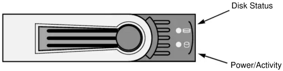
Viewing Logical Drive Information
To view information for a single logical drive:
- Click the Disk Arrays icon.
- Click the Disk Array icon.
-
Click the Logical Drives icon
-
Click the Subsystem icon in Tree View.
-
Click the Logical Drive icon.
To specify an Alias or set the Read and Write Policies, click the Settings tab.
Logical Drive Status
See "Logical Drive Status" on page 172.
Logical Drive Synchronization
Synchronization is an automatic procedure applied to logical drives when they are created. "Yes" means the logical drive was synchronized.
Adjustable Items
- Alias – Optional
- Read Policy
- Write Policy
See "Changing Logical Drive Settings" on page 174.
Viewing Logical Drive Statistics
To view information for a single logical drive:
- Click the Subsystem icon in Tree View.
- Click the Disk Arrays icon.
- Click the Disk Array icon.
- Click the Logical Drives icon
- Click the Logical Drive icon.
- From the dropdown menu on the Information tab, choose Statistics.
Changing Logical Drive Settings
To make logical drive settings:
- Click the Subsystem icon in Tree View.
- Click the Disk Arrays icon.
- Click the Disk Array icon.
- Click the Logical Drives icon
- Click the Logical Drive icon.
- Click the Settings tab in Management View.
- Optional. Enter an alias in the Logical Drive Alias field.
Maximum of 32 characters. Use letters, numbers, one space between words, and underscore. An alias is optional.
- From the Read Policy dropdown menu, choose a Read Cache policy.
The choices are Read Cache, Read Ahead, and No Cache. See “Choosing Cache Policy” on page 245.
- From the Write Policy dropdown menu, choose a Write Cache policy.
The choices are Write Back and Write Through. If you chose No Read Cache, Write policy is automatically Write Through. See “Choosing Cache Policy” on page 245.
- Click the Submit button.
Initializing a Logical Drive
Initialization sets the data bits in the logical drive to zero. The action removes any residual data left behind from earlier configurations. Initialization is recommended for new logical drives. You can also initialize an existing logical drive. See “Initialization” on page 247 for more information.

Warning
When you initialize a logical drive, all the data the logical drive will be lost. Backup any important data before you initialize a logical drive.
To initialize a logical drive:
- Click the Subsystem icon in Tree View.
- Click the Logical Drive Summary icon.
- Click the icon of the logical drive you want to Initialize.
-
From the dropdown menu on the Background Activities tab, choose Initialization.
-
To choose Quick Initialization, check the box.
- If you checked the Quick Initialization box, enter a value in the Quick Initialization Size field. This value is the size of the initialization blocks in MB.
-
If you did not choose Quick Initialization, enter a hexadecimal value in the Initialization Pattern in Hex field or use the default 00000000 value.
-
Click the Submit button.
-
In the confirmation box, type the word confirm in the field provided.
- Click the OK button.
To view the progress of the Initialization, click the Background Activities tab.
To set Initialization priority, see “Making Background Activity Settings” on page 137.
You can also start Initialization from the Subsystemicon, Background Activities tab.
Running Redundancy Check
Redundancy Check is a routine maintenance procedure for fault-tolerant disk arrays (those with redundancy) that ensures all the data matches exactly. Redundancy Check can also correct inconsistencies. You can also schedule a Redundancy Check. See “Scheduling an Activity” on page 139.
Redundancy Check a Logical Drive:
- Click the Subsystem icon in Tree View.
- Click the Logical Drive Summary icon.
- Click the icon of the logical drive you want to Redundancy Check.
- From dropdown menu on the Background Activities tab, choose Redundancy Check.
- To choose Auto Fix, check the box.
This feature attempts to repair the problem when it finds an error.
- To choose Pause On Error, check the box.
This feature stops the process when it finds an error.
If Auto Fix is also checked, the process stops only when it finds a non-repairable error.
- Click the Submit button.
To view the progress of the Redundancy Check, click the Background Activities tab.
To set Redundancy Check priority, see “Making Background Activity Settings” on page 137.
You can also start Redundancy check from the Subsystemicon Background Activities tab
Viewing the Logical Drive Check Table
The Logical Drive Check Table displays errors related to a logical drive. Use this information to evaluate the integrity of the logical drive and to determine whether corrective action is needed. To View the tables:
- Click the Subsystem icon in Tree View.
-
Click the Disk Arrays icon.
-
Click the Disk Array icon.
- Click the Logical Drives icon
- Click the Logical Drive icon.
- Click the Check Table tab in Management View.
- Click the option for the table you want to see.
The default is All tables.
If there are entries, they are listed as follows:
• Entry Number – A number assigned to each block of entry.
- Table Type – Read Check, Write Check or Inconsistent Block (see below).
- Start Logical Block Address – LBA of the first block for this entry.
- Count – Number of continuous blocks starting from this LBA.
- Read Check Table – Contains a list of read errors for this logical drive.
• Write Check Table – Contains a list of write errors for this logical drive.
- Inconsistent Block Table – Contains a list of inconsistent blocks for this logical drive.
- Mirror data for RAID Levels 1, 1E, and 10.
- Parity data for RAID Levels 5, 6, 50, and 60.
- Inconsistent blocks are identified by the Redundancy Check.
Managing Spare Drives
When a physical drive in a disk array fails and a spare drive of the same type and adequate capacity is available, the disk array will begin to rebuild automatically using the spare drive.
See “Hot Spare Drive” on page 248 and “Rebuilding a Disk Array Automatically” on page 270.
Spare drive management includes the following functions:
- Viewing a List of Spare Drives (page 178)
- Creating a Spare Drive (page 179)
- Deleting Spare Drive (page 180)
- Making Spare Drive Settings (page 180)
- Running Spare Check (page 181)
Viewing a List of Spare Drives
To view a list of spare drives:
- Click the Subsystem icon in Tree View.
- Click the Spare Drives icon.
The information includes:
- ID – The unique ID number assigned to the spare drive.
- Operational Status – OK is normal. Can also show Rebuilding, Transition Running, PDM Running, or Offline.
- Physical Drive ID – The ID number of the physical drive assigned as a spare
• Capacity – The data storage capacity of this spare drive. - Revertible – Yes or No. A revertible spare drive automatically returns to its spare drive assignment after the failed physical drive in the disk array is replaced. See “Transition” on page 256 for more information.
- Type – Global, can be used by any disk array. Dedicated, can only be used by the assigned disk arrays.
• Dedicated to Disk Arrays – For dedicated spares, the disk arrays to which they are assigned. Global spares show N/A.
Creating a Spare Drive

Important
- There must be an unconfigured physical drive available to assign as a spare drive. See “Viewing a List of Physical Drives” on page 149.
- Be sure the spare drive you choose has capacity equal to or greater than the smallest physical drive assigned to the disk array.
- A dedicated spare drive must be the same media type, HDD or SDD, as the other physical drives in the disk array.
- Free of any previous configuration data. See “Clearing Stale and PFA Conditions” on page 152 or page 269.
To create a spare drive:
- Click the Subsystem icon in Tree View.
- Click the Spare Drives icon.
- Click the Create tab in Management View.
- Choose a spare type, Global or Dedicated and click the Next button.
- To make a revertible spare drive, check the Revertible box.
- To enable Media Patrol on this spare drive, check the Enable Media Patrol box.
- Dedicated spare drives only. Choose a type of physical drive from the Media Type dropdown menu.
HDD is a hard disk drive. SSD is a solid state drive. Physical drive type of the spare must match the disk array.
- In the Physical drives field, highlight the physical drive you want to assign as a spare drive in the Available list and press the >> button to move the drive to the Selected list.
You can also double-click drives to move them.
- Dedicated spare drives only. In the Dedicated to Disk Arrays field, highlight disk array to which you want assign the spare drive from the Available list and press the >> button to move the array to the Selected list.
You can also double-click arrays to move them.
- Click the Update button.
Your choices are displayed under New Hot Spare Drives.
- If you agree with the proposed choices, click the Submit button.
Deleting Spare Drive

Note
If an existing spare drive has the wrong parameters for your needs, click the Settings tab to change the parameters rather than delete the spare drive and create a new one.
To delete a spare drive:
- Click the Subsystem icon in Tree View.
- Click the Spare Drives icon.
- Click the Delete tab in Management View.
- Check the box to the left of the spare drive you want to delete.
- Click the Submit button.
In the confirmation box, type the word confirm in the field provided.
- Click the OK button.
Making Spare Drive Settings
To change spare drive settings:
- Click the Subsystem icon in Tree View.
- Click the Spare Drives icon.
- Click the Spare Drive icon.
- Click the Settings tab in Management View.
- Choose a spare type, Global or Dedicated.
- To make a revertible spare drive, check the Revertible box.
- To enable Media Patrol on this spare drive, check the Enable Media Patrol box.
- If you chose a Dedicated spare drive, in the Dedicated to Disk Arrays field, highlight the disk array to which you want assign the spare drive from the Available list and press the >> button to move them to the Selected list.
You can also double-click array to move it.
- Click the Submit button.
Running Spare Check
Spare Check verifies the operational status of your spare drives. You can also schedule a Spare Check. See “Scheduling an Activity” on page 139.
To check a spare drive:
- Click the Subsystem icon in Tree View.
- Click the Spare Drives icon.
- Click the Spare Check tab in Management View.
- From the Physical Drive dropdown menu, choose the spare drive you want to check.
Or choose All to check all the spare drives at the same time.
- Click the Submit button.
The results of the Spare Check appear under Spare Check Status in the Information tab. "Healthy" means normal condition.
Working with the Logical Drive Summary
The Logical Drive Summary displays a list of all logical drives under the SuperTrak controller including logical drives in expanded or cascaded enclosures. This list does not arrange the logical drives under the disk array to which they belong nor under the enclosure in which they are located.
Logical Drive Summary includes the following functions:
- Viewing a List of All Logical Drives (page 182)
- Locating a Logical Drive (page 182)
- Viewing Individual Logical Drive Information (page 183)
Viewing a List of All Logical Drives
To view a list of all logical drives in all enclosures:
- Click the Subsystem icon in Tree View.
- Click the Logical Drive Summary icon.
Locating a Logical Drive
Virtual or Third Party Enclosures
Support for this feature depends on how your system or enclosure was set up. Direct-connect systems with individual LED connections and SGPIO enclosures support individual physical drive LEDs. Other systems or enclosures might or might not support them. See “Appendix D: LED Backplane Connections” on page 295.
To locate a logical drive in the enclosure, click the Locate LDx button. The LEDs for the carriers holding the physical drives used by the logical drive will blink for one minute.
Promise Enclosures
To locate a logical drive in the VTrak JBOD enclosure, click the Locate LDx button. The disk status LEDs will blink for one minute to identify the carriers holding the physical drives used by the logical drive.
Figure 9. VTrak drive carrier LEDs
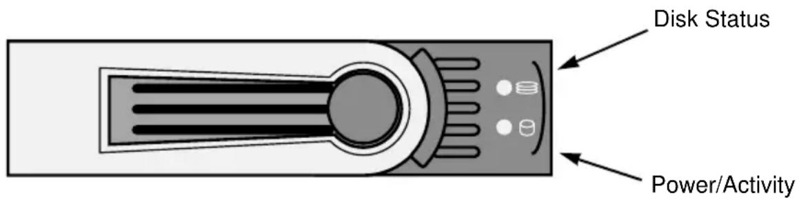
Viewing Individual Logical Drive Information
- Click the Subsystem icon in Tree View.
- Click the Logical Drive Summary icon.
- Click the Logical Drive icon.
The information and location for the logical drive appear in Management View. See Viewing Logical Drive Information (page 173).
Chapter 6: Management with the CLI
- Opening the CLI on Windows (below)
- Opening the CLI on Linux, FreeBSD, and VMware (page 186)
• Table of Supported Commands (page 187)
• Notes and Conventions (page 189)
• List of Supported Commands (page 190)
SuperTrak EX Controller's Command Line Interface (CLI) provides rapid setup of disk arrays and logical drives. You can also manage your SuperTrak system using the CLI. However, ongoing management is much easier with the SuperBuild utility or WebPAM PRO.
Opening the CLI on Windows
To open the CLI, click the CLI icon on the desktop (right), or:

- Go to Start > Run and click the Browse button.
- Navigate to the C:\Program Files\WebPAMPRO\Agent\bin folder.
- Click cliib.exe file then click the Open button.
- Click the OK button in the Run dialog box.
The CLI window opens.
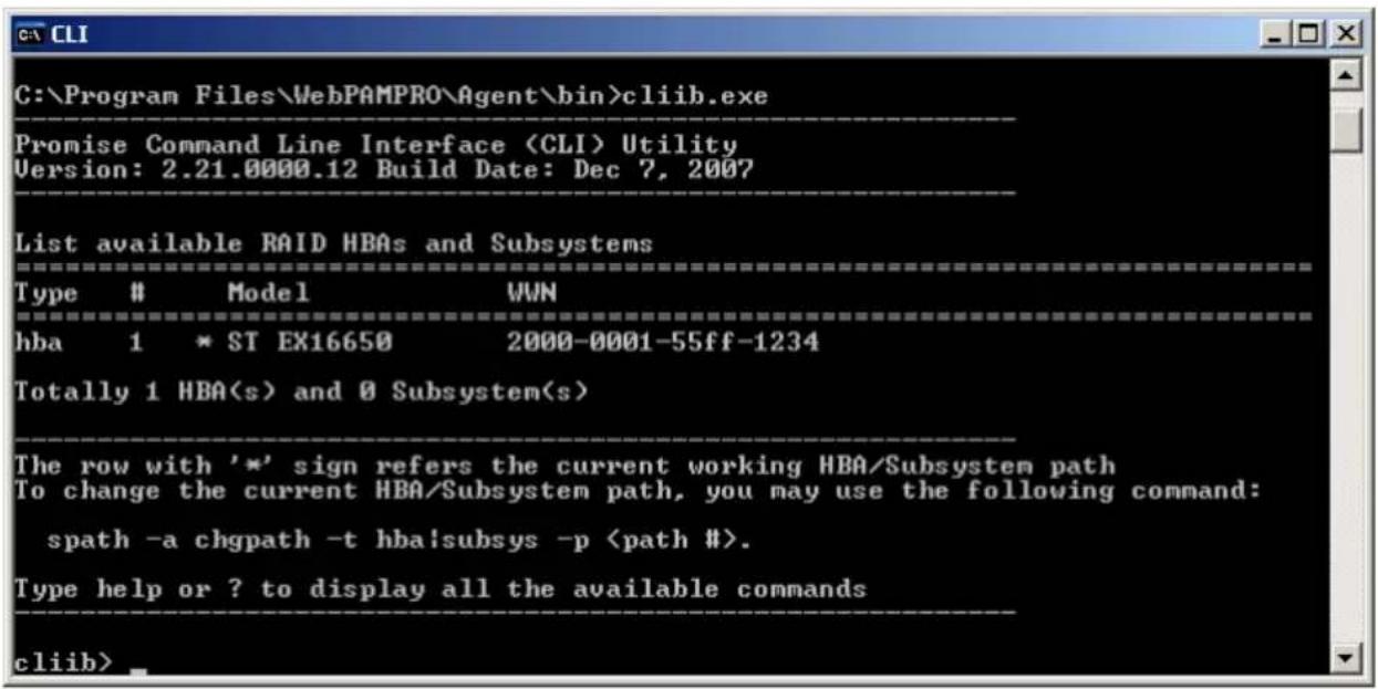
Opening the CLI on Linux, FreeBSD, and VMware
To open the CLI:
- Open a terminal window.
- Go to the /opt/Promise/WebPAMPRO/Agent directory.
- Type ./startCLI.sh and press Enter.
The CLI runs in the terminal window.
![[root@vampire ~]# cd /opt/Promise/WebPAMPRO/Agent [root@vampire Agent]# startCLI.sh Promise Command Line Interface (CLI) Utility Version: 2.21.0000.12 Build Date: Dec 7, 2008 List available RAID HBAs and Subsystems Type # Model WWN hba 1 * ST EX16650 2000-0001-55ff-1234 Totally 1 HBA(s) and 0 Subsys…](/content/2026/05/785299/images/348a6b74723f4491a81bb7c1a47de26c62b2a4160f4492cbe7388212b9529b00.jpg)
Table of Supported Commands
| Command Action | |
| about View utility information. | |
| array View or edit array information. Create, edit, or delete a new or existing array. Create, edit, or delete logical drives in an existing array. To physically locate an array in an enclosure. Accept an incomplete array condition. | |
| battery Subsystems only. View battery information or to recondition a battery. | |
| bbm View or clear the BBM defect list of the specified configured physical drive. | |
| bga View status of all current background activities. Enable or disable relevant background activities. Modify the background task rate for each of the background tasks. | |
| buzz View buzzer status, enable/disable and turn on/off buzzer. | |
| checktable View logical drive error tables. | |
| config For express or automatic configuration. For advanced configuration please see the 'array' command. | |
| ctrl View or edit controller information and settings. | |
| date View or edit system time. | |
| enclosure View or edit enclosure and SEP information and settings. Locate an enclosure via LEDs. | |
| event View or clear events logs. | |
| export Subsystems only. Export files to remote tftp host. | |
| factorydefaults Restore settings to factory defaults. | |
| init View logical drive initialization status and progress. Start, stop, pause, or resume an initialization or a quick initialization. | |
| Command | Action |
| logdrv View or edit | logical drive information and settings. Locate a logical drive via LEDs. |
| migrate Start and monitor disk array migration process. | |
| mp View media patrol status and progress. Start, stop, pause, or resume media patrol. | |
| pdm View PDM status and progress. Start, stop, pause, or resume PDM process. | |
| phydrv View or edit physical drive information and settings. Locate a physical drive via LEDs. | |
| ptiflash Update system software and firmware through local host. | |
| rc View redundancy check status and progress. Start, stop, pause or resume redundancy check. | |
| rb View rebuild status and progress. Start, stop, pause, or resume a rebuild process. | |
| sc View spare check status. Start spare check. | |
| smart View SMART logs and enable SMART on physical drives. | |
| spare Create or modify hot spare drives. | |
| spath Discover and change subsystem path. | |
| stats View or reset statistics. | |
| subsys View or edit subsystem information and settings. | |
| sync | View logical drive synchronization status and progress. |
| topology | View SAS topology, the physical connections and device information. For products that support multiple enclosures only. |
| transit View transition status and progress. Start, stop, pause, or resume a transition process. | |
| help | When used alone will display this menu. When used in conjunction with a command (example: help array) it will display help information for that particular command. |
| Command Action | |
| ? This can be used | in place of the help command or optionally can be used as a switch for a command (example: array -?) to provide command usage. |
| Note: Commands are NOT case sensitive. | |
Notes and Conventions
Commands and options are NOT case sensitive.
Not all extended keys are supported. However, you can use the backspace and the left and right arrow keys for command line editing. In addition, the up and down arrow keys allow scrolling through the command history buffer.
If you need context-sensitive help, type one of the following commands:
-h -? - help
That action will display full context-sensitive help for the specific command.
Each command when used alone, such as “array” will display a summary of relevant information. If more information is desired, the -v verbose mode can be used. This will provide information for all relevant aspects of that command.
Usage terminology is as follows:
• [square braces] depict an optional switch
-
- Type " | more" at the end of each command, to display info page by page
List of Supported Commands
| • about (page 190) | • migrate (page 210) |
| • array (page 190) | • mp (page 211) |
| • battery (page 194) | • pdm (page 211) |
| • bbm (page 195) | • phydrv (page 212) |
| • bga (page 195) | • ptiflash (page 215) |
| • buzz (page 198) | • rc (page 216) |
| • checktable (page 198) | • rb (page 217) |
| • config (page 199) | • sc (page 218) |
| • ctrl (page 200) | • smart (page 219) |
| • date (page 203) | • spare (page 219) |
| • enclosure (page 203) | • spath (page 221) |
| • event (page 205) | • stats (page 221) |
| • export (page 206) | • subsys (page 222) |
| • factorydefaults (page 206) | • sync (page 223) |
| • init (page 207) | • topology (page 224) |
| • logdrv (page 209) | • transit (page 224) |
about
Usage
about
Summary
Displays utility information.
array
Usage
array [-a "] [-d
"] array -a mod -d
"]
array -a del -d
array -a locate -d
array -a accept -d
array -a addld -d "
array -a delld -l
The array command is the main command for performing advanced configuration and maintenance tasks on disk arrays.
This command lists, creates, modifies, deletes, and locates disk arrays. It also adds and deletes logical drives.
Note that you cannot mix Hard Disk Drives (HDD) and Solid State Drives (SSD) in the same disk array.

Warning
When you delete a disk array, you also delete any logical drives that belong to it, along with the data they contain.
When you initialize a logical drive, you delete all data on the logical drive.
Back up any important data before deleting a disk array or logical drive.
Options
-a
list (Default) Displays a summary of all arrays, a specified number of arrays, or a specific array.
add Adds/creates an array. This action might also create logical drives at the same time.
addld Adds/creates a logical drive to an existing array.
delld Deletes a logical drive from an array.
mod
Modifies
array
settings.
del Deletes an array and all its associated logical drives.
locate Locates an array.
accept Accepts the condition of an incomplete array. Currently,
there are two conditions that can cause an array to be incomplete:
- "Missing Drive: one or more drives missing in the array
- "Missing NVRAM Watermark The migration watermark is not found on the controller but the DDF on the array indicates that migration is in progress.
When the either of the above conditions occurs, all the logical drives on the array go offline.
You can accept the array in incomplete condition and try to bring the logical drives online. However, that is a high-risk and non-revertible operation, and it may result in data loss. Therefore, it is recommended to clear the condition first, for example: putting the missing drives back or roaming the array back to the original controller and wait until the migration completes.
transport Takes the array and the logical drives on the array offline to get ready for transport the array to another subsystem.
-d
-p
-s "
alias= A user-specified array name. Up to 32 characters, alpha- numeric characters, blank spaces and underscores. Beginning and ending blank spaces are discarded.
mediapatrol= Enables or disables Media Patrol for this array. enable The default is enable. disable pdm= Enables or disables PDM for this array. enable The default is enable. disable
-1 "
ID= Assigns a specific ID to an array. Overrides automatic ID assignment. Valid values are 0-255.
Alias= A user-specified name for the logical drive.
Raid= Specifies logical drive RAID level.
0 Striping.
1 Mirroring on two drives.
5 Parity, requiring 3 or more drives.
10 Mirroring on even number of drives.
1e Extended mirroring, requiring 2 or more drives.
50 Striping on multiple RAID 5, requiring 6 or more drives.
6 Allow two drive failure, requiring 4 or more drives.
60 Striping on multiple RAID 6, requiring 8 or more drives.
Capacity= Specifies logical drive capacity. Can be specified in megabytes (mb), gigabytes (gb) or terabytes (tb), up to 2 decimal places. If not specified, all available capacity is used for this logical drive.
Stripe= Specifies logical drive stripe size. Options include 64KB, 128 KB, 256 KB, 512 KB, and 1024 KB. If not specified, the default 64KB is used.
Sector= Specifies logical drive sector size. Options include 512 B, 1 KB, 2 KB, and 4 KB. Sector size cannot exceed Stripe size. Auto-adjusted not to exceed the maximum supported sector size of the controller. See controller information on page 200. If not specified, the default 512 B is used.
WritePolicy= Specifies logical drive write policy.
writethru Writes are not cached
writeback Writes are cached
ReadPolicy= Specifies logical drive read policy.
readahead Reads extra data to help reduce read times of sequential data.
readcache Caches reads the data in case the same request is made again.
nocache No caching algorithm.
Axle= A member element when creating a RAID10 or RAID50 or RAID60. RAID10 have 2 axles, RAID50 and RAID60 may have up to 16 axles with up to 16 drives per axle.
PreferredCtrlId= Subsystems only. Specifies which controller the LD is preferred for LUN affinity. Valid value is 1 or 2. If value is not specified, LUN affinity is auto balanced.
-c
-t
missingdrive The condition of missing drive in the array.
missingwatermark The condition of missing NVRAM watermark of the array.
-v Verbose mode. Displays all array properties, requires -a list option.
Examples
array -v -c 1
array -a add -s "alias=MyArray,mediapatrol=enable"-p 1,3,5\~9
-1 "raid=5, capacity=50gb, stripe=256kb, sector=1kb"
array -a add -p 1,3,5\~9 -l "raid=5,capacity=50gb,stripe=256kb"
-1 "raid=0, capacity=100gb"
array -a mod -d 1 -s "alias=YourArray,mediapatrol=disable"
array -a del -d 3
battery -a recondition -b
Summary
The battery command displays the status of a battery by the percentage of charge left.
On subsystems, this command also reconditions the battery. Reconditioning fully discharges then fully recharge the battery. The battery is reconditioned automatically once per month.
Options
-a
list (Default) List information for all batteries or a specific battery.
recondition Subsystems only. Recondition a specific battery.
-b
1..2
Examples
battery
battery -a recondition -b 1
bbm
Usage
bbm [-a
bbm -a clear -p
Summary
The bbm command displays and clears the Bad Block Map (BBM) for all configured SATA drives.
Options
-a
list (Default) List the BBM information.
clear Clears the BBM list. For configured SATA drives only.
-p
default is all physical drives. For the -a clear option, you must specify a physical drive id.
Examples
bbm -p 1
bbm -a clear -p 3
bga
Usage
bga [-a
bga -a mod -s ""
Summary
The bga command displays all current background activities and makes settings each background activity.
Options
-a
list (Default) Lists current background activities.
mod Makes changes to one of the settings.
-s "
autorebuild= Enable or disables auto-rebuild and auto-transition.
Auto-rebuild will rebuild an array when an unconfigured drive is inserted into the slot of a dead drive.
Auto-transition will start transitioning on a used revertible spare in the following condition:
- When the rebuild has completed using the revertible spare, and
- When an unconfigured drive is inserted into the slot of the dead drive which the was part of the array. or
When a non-revertible spare has been inserted or created, and is applicable to the array.
This option affects all arrays on the subsystem.
enable
disable
mediapatrol= Verifies the media of the array and/or spares to find bad blocks on physical disks before you use that block. This feature is enabled and disabled on an array basis.
enable
disable
ReassignedBlock=Threshold value to trigger PDM, when re-assign map exceeds the threshold value
1..512
ErrorBlock= Threshold value to trigger PDM, when number of medium error on the PD exceeds the threshold value.
1..2048
rebuildrate= Rebuild rate determines the rate at which rebuild will run.
(low=25, medium=50, high=75)
low
medium
high
pdmrate= PDM rate determines the rate at which PDM will run.
(low=25, medium=50, high=75)
low
medium
high
transitionrate= Transition rate determines the rate at which transition will run. (low=25, medium=50, high=75)
low
medium
high
syncrate= Synchronization rate determines the rate at which synchronization will run. (low=25, medium=50, high=75)
low
medium
high
initrate= Initialization rate determines the rate at which initialization will run. (low=25, medium=50, high=75)
low
medium
high
rcrate= Redundancy check rate determines the rate at which redundancy check will run. (low=25, medium=50, high=75)
low
medium
high
migrationrate= Migration rate determines the rate at which migration will run. (low=25, medium=50, high=75)
low
medium
high
Examples
bga
bga -a mod -s "autorebuild=enable,rebuildrate=high,syncrate=low"
buzz
Usage
buzz [-a
buzz -a list
buzz -a enable
buzz -a disable
buzz -a on
buzz -a off
Summary
The buzz command displays the status of the buzzer, and enables, disables, turns on or turns off the buzzer.
Options
-a
list (Default) List the status of the buzzer.
enable Enable the buzzer.
disable Disable the buzzer.
on Turn on the buzzer.
off Turn off the buzzer.
checktable
Usage
checktable [-t
Summary
The checktable command displays the error check tables of a logical drive.
Options
-t
rct Displays the read check table.
wct Displays the write check table.
ibt Displays the inconsistent block table.
-1
Examples
checktable -l 10 -t rct
checktable -l 10
config
Usage
config -a auto
config -a expr [-r y|n] [-c y|n] [-p y|n] [-m y|n] [-s y|n] [-t
Summary
The config command has two options: Automatic and Express.
Automatic configuration takes all available unconfigured physical drives to create an optimized disk array following a default set of parameters. There are no options.
Express configuration takes your input, creates one or two arrays, and spreads their capacity evenly over all of the logical drives that you specify.
The redundancy option creates redundant logical drives (RAID 1, 10, 1E, 5, 50, 6, or 60).
The capacity option enables optimizes the logical drives for capacity.
The performance option optimizes the logical drives for performance.
If you choose all three options, redundancy gets highest priority and capacity gets lowest priority.
Note that you cannot combine HDDs and SSDs in the same disk array. If your system has both type of drives, it will create separate disk array/logical drive sets for each type of physical drive.
Options
-a <action> Specifies the action to perform.
auto Automatic configuration with no options.
Creates an optimized disk array. One or more logical drives are created automatically.
expr Express configuration. RAID level is dependant on the options chosen.
-r
-p
-c
-m
-s
-t
video Sequential large block reads.
data Random read/write mix, small to medium sized IO.
log Sequential small block write.
other Random read/write mix, small to medium sized IO.
fileserver Random read/write mix, small to medium sized IO.
-I
Examples
config -a auto
config -a expr -ry -p y -c n -sy -t data -l2
ctrl
Usage
ctrl [-a
ctrl -a mod [-i "
ctrl -a clear [-i
Summary
The ctrl command displays controller information and changes controller settings.
Options
-a
list (Default) Lists controller information.
mod Changes controller settings.
clear Clears controller conditions.
-i
-c
-s "
alias= A user-specified name for the controller. Up to 48 characters long, alpha- numeric characters, blank spaces and underscores. The beginning and ending blank spaces are discarded.
Following setting is shared if there are dual controllers:
coercion= Enables or disables disk coercion. Disk coercion will truncate the size of the physical drives. Makes different size drives appear to be the same size. For example, a 90.1 GB drive would appear as the same size as an 89.8 GB drive. Important when using drives of different manufacturers for rebuilds or as hot spares.
enable
disable
coercionmethod= The method of coercion.
GBTruncate Truncates the drive to the nearest 1-billion byte boundary.
10GBTruncate Truncates the drive to the nearest 10-billion byte boundary.
GrpRounding Truncates the drive using an intelligent algorithm. Allows the maximum amount of usable space.
TableRounding Truncates the drive using a pre-defined coercion table.
smart= Enables or disables polling drive SMART status.
enable
disable
smartpollinginterval= Sets the time interval in number of minutes to poll the drive SMART status.
1..1440
cacheflushinterval= Sets the time interval in seconds to flush the controller writeback cache.
1..12
migrationstorage= Sets location to store the migration watermark.
ddf Uses the DDF area on the physical drives of the disk array.
nvram Uses the NVRAM on the controller.
lunaffinity= Subsystems only. Enables or disables LUN affinity, allowing LD access only to certain controller. For subsystems with dual controllers.
enable
disable
pollinterval= Sets interval in seconds to poll enclosure SEP information.
15..255
lunmapping= Subsystems only. Chooses WWN based or Slot based LUN mapping method.
wwn
slot
adaptivewbcache= Enables or disables adaptive writeback cache.
enable Writeback logical drives will change the write policy based on the availability of protection. If BBU or UPS is available, the write policy is retained as Writeback, otherwise the policy is switched to Writethru.
disable The write policy of the writeback logical drives are not changed irrespective of the availability of BBU or UPS.
hostcacheflushing= Subsystems only. To enable or disable host cache flushing. When enabled, SYNCHRONIZE CACHE SCSI command from host is supported.
For high availability products only.
enable
disable
forcedreadahead=Enables or disables forced read ahead caching.
enable
disable
commonwwnn= Enables or disables common WWNN. For subsystems with dual controllers.
enable All controllers report one common WWNN.
disable Each controller reports its own WWNN.
alua= Subsystems only. Enables or disables asymmetric logical unit access. Enabling ALUA will enable LUN affinity automatically.
enable
disable
-t
Valid only when the command action is "clear".
watermark Watermark, the only supported condition for now.
Used with the -a clear option to clear an orphan migration watermark in the controller NVRAM. This action only works when migration storage is set to NVRAM prior to starting migration.
-I Displays the id of the controller on whose serial port the CLI is running.
-v Verbose mode. Used with the -a list option.
Examples
ctrl
ctrl -v
ctrl -l
ctrl -a mod -i 1 -s "alias=ctrl1, coercion=enable"
date
Usage
date
date -a mod [-d
Summary
The date command displays the system time and date, and changes these settings.
Options
-a
list (Default) Displays the current system time.
mod Modifies the current system time.
Not supported for HBA products.
-d
yyyy/mm/dd where month's range is 1-12 and day's range is 1-31.
-t
hh:mm:ss where hour range is 0-23, minute and second range is 0-59.
Examples
date
date -a mod -d 2004/02/25 -t 14:50:05
enclosure
Usage
enclosure [-a
enclosure -a mod [-e
enclosure -a locate [-e
Summary
The enclosure command provides status and information about the various components of the enclosure unit. It is also sets temperature threshold values for JBOD enclosures and displays Vendor Provided Data (VPD).
Options
-a <action> Specifies the action to perform.
list (Default) Displays information and status of the enclosure.
mod Modifies settings. Requires the -s option.
locate Locates an enclosure by flashing its LEDs.
-e <encl id> Enclosure ID. The default value is 1 if unspecified.
For list action, the default is for all enclosures if unspecified.
-s "<option>=<value>" Specifies the settings to change. Applies to the JBOD enclosures only.
tempwarning= Enclosure warning threshold temperature, in degrees Celsius.
10..51
tempcritical= Enclosure critical threshold temperature, in degrees Celsius.
52..61
ctrltempwarning= Controller warning threshold temperature, in degrees Celsius.
10..61
ctrltempcritical= Controller critical threshold temperature, in degrees Celsius.
62..71
-t <FRU type> Specifies which type of FRU to locate. Requires -a locate option.
ctrl Locates the controller.
cooling Locates the cooling unit. Only works with SAS type enclosure.
psu Locates the power supply unit. Only works with SAS type enclosure.
-f <FRU id> Specifies id of FRU to locate. Requires -a locate option.
Valid values are 1 and 2.
-v Verbose mode. Requires -a list option. VPD information is displayed.
Examples
enclosure
enclosure -v
enclosure -a mod -e 10 -s "tempwarning=35, tempcritical=45"
event
Usage
event [-a
event -a clear [-l
Summary
The event command displays and clears the RAM and NVRAM event logs.
Options
-a
list Displays the events for the specified location.
RAM events are displayed if no location is specified.
clear Clear events for a specified location.
-I
ram All events are stored in RAM.
These events are lost after rebooting.
nvram Some events are also stored in NVRAM.
These events remain after rebooting and are a subset of the RAM events.
-i
-c
-v Verbose mode. Requires the -a list option.
Examples
event
event -v
event -l nvram
event -a clear -Invram
event -c 200
event -a list -i852 -c200
export
Usage
export -t
Summary
The export command exports certain types of configuration files to a remote or local host.
This command only affects subsystems.
Options
-t
-f
-s
-p
Examples
export -t userdb -s 192.168.1.1 -f userdb.bin export -t servicereport -s 192.168.1.1 -f servicereport # for embedded export -t servicereport -f servicereport # for in-band
factorydefaults
Usage
factorydefaults -a
Summary
The factorydefaults command restores factory default settings.
Options
-a
-t
allsw Subsystems only. All software settings.
Following are individual Firmware settings:
bga Background activity settings.
ctrl Controller settings.
encl Enclosure settings, including temperature thresholds.
fc Subsystems only. FC port settings.
iscsi Subsystems only. iscsi settings, including node, port, SLP, and iSNS.
netiscsi Subsystems only. Network settings of iSCSI ports.
netmgmt Subsystems only. Network settings of management ports.
phydrv Physical drive settings.
sas Subsystems only. SAS host interface port setting.
scsi Subsystems only. Parallel SCSI channel settings.
subsys Subsystem settings.
Following are individual Software settings, which only apply to Subsystems:
bgascheduler Background activity scheduler settings.
service Service startup type settings.
webserver Web server settings.
snmp SNMP settings.
telnet Telnet settings.
email Email settings.
netsend Netsend settings.
cim CIM settings.
user User settings.
Examples
factorydefaults -a restore -t phydrv
factorydefaults -a restore -t all
init
Usage
init [-a
init -a start -l
init -a stop -l
init -a pause -l
init -a resume -l
Summary
The init command starts, stops, pauses, and resumes a logical drive initialization.
A full initialization writes to the entire logical drive space and takes several minutes, depending on the size of the logical drive.
A quick initialization writes to the first and last few megabytes of the logical drive. Typically, a quick initialization is completed in moments.

Warning
When you initialize a logical drive, you delete all data on the logical drive. Backup any important data before you initialize a logical drive!
Options
-a
list Displays a list of the initializations in progress or paused and their status. The default action.
start Start an initialization.
stop Stop an initialization.
pause Pause an initialization.
resume
Resume
an
initialization.
- I
-q
1..1024
-p
The pattern can range from 1 to 128 bytes (HEX string), and is padded to even number of bytes, such as, fff padded to 0fff.
Pattern is not supported for quick initialization.
Examples
init
init -a stop -10
init -a start -l0 -p5a5a0101
logdrv
Usage
logdrv [-a <action>] [-l <LdId>] [-c <Ld count>] [-v]
logdrv -a locate -l <LdID>
logdrv -a mod -l <LdId> -s "<list of ld settings>"
Summary
The logdrv command displays information about the logical drives and changes logical drive settings.
To create a logical drive, see the array command on page 190.
Options
-a <action> Specifies the action to perform.
list (Default) Displays a summary of one or more logical drives.
mod Changes logical drive settings.
locate Locates a logical drive within the enclosure by flashing drive carrier LEDs.
-I [<LD ID>] Logical drive ID.
-c [<LD count>] Logical drive count. Requires the -a list option.
-s ["<option>=<value>"] Specifies the logical drive settings to change.
    alias= A user-specified name for the logical drive.
    Up to 32 characters, containing alpha-numeric characters, blank spaces and underscores. Beginning and ending blank spaces are discarded.
WritePolicy= Specifies logical drive write policy.
writethru Writes are not cached.
writeback Writes are cached. Note: Cannot be set if ReadPolicy is set to "nocache."
ReadPolicy= Specifies logical drive read policy.
readahead Reads extra data to help reduce read times of sequential data.
readcache Caches reads in the case the same request is made again.
-V
nocache No caching algorithm.
Specifies which controller the LD is prefers for LUN affinity. Valid value is 1 or 2.
Verbose mode. Used with -a list.
Examples
logdrv
logdrv -v
logdrv -a mod -l0 -s "readpolicy=readahead"
logdrv -a locate -l2
migrate
Usage
migrate [-a
migrate -a start -d
Summary
The migrate command expands the capacity of a logical drives (online capacity expansion) and changes logical drive RAID levels (RAID level migration).
Note that the added drives must be the same media type, HDD or SSD, as the other physical drives in the disk array.
Options
-a
list (Default) Displays the migration status of specified disk array. If no array ID specified, all migration statuses are displayed.
start Starts the migration.
-d
-p
-1 "
id= (Required) Specifies the logical drive ID.
capacity= Specifies the new logical drive capacity.
Specify a value only when expanding logical drive capacity.
raid= Specifies the new RAID level.
Note: When expanding a RAID 10 logical drive, specify RAID 10 as the target RAID level, otherwise the resulting logical drive is a RAID 1E.
axle= Specifies the axle number.
Applies to RAID 50 and 60 when the RAID Level is changed.
stripe= Specifies the new stripe size.
Not currently supported.
Examples
migrate -d 1
migrate -a start -d 1 -p 10 -l "id=0, capacity=10gb"
mp
Usage
mp -a
Summary
The mp command activates Media Patrol. Media Patrol searches the physical drives for media errors. When an error is found, Media Patrol attempts to repair the error. If it fails to correct the error, Media Patrol attempts to remap the sector. Note: Sector remapping is not currently supported.
You can start, stop, pause, or resume Media Patrol and monitor its progress and status.
Options
-a
list (Default) Displays the status and progress of Media Patrol.
start
Starts
Media
Patrol.
stop Stops Media Patrol.
pause Pauses Media Patrol.
resume Resumes a paused Media Patrol.
Examples
mp
mp -a stop
mp -a resume
pdm
Usage
pdm [-a
pdm -a start -d
pdm -a stop -d
pdm -a pause -d
pdm -a resume -d
Summary
The pdm command activates Predictive Data Migration (PDM). PDM replaces a suspect physical drive, such as a drive with a PFA condition, with a different drive. The replacement drive can be an unconfigured drive, a global spare, or a dedicated spare to this disk array.
During PDM, the data on the suspect drive is transferred to the replacement drive while the logical drive remains online.
After PDM, the replacement drive becomes part of the disk array. The suspect drive become unconfigured and any PFA condition remains on it.
This command starts, stops, pauses, and resumes a PDM and monitors the progress of a running PDM.
A PFA drive cannot be used until you clear the PFA condition. To clear the PFA condition of a physical drive, please refer to phydrv command on page 212.
Note that the destination drive must be the same media type, HDD or SSD, as the other physical drives in the disk array.
Options
-a
list (Default) Displays the active and paused PDMs and their status.
start Starts a manual PDM.
stop Stops a PDM.
pause Pauses a PDM.
resume Resumes a paused PDM.
-d
-s
-p
Examples
pdm
pdm -a start -d0 -s2 -p10
pdm -a stop -d0 -s2
phydrv
Usage
phydrv [-a
phydrv -a mod -p "
phydrv -a locate -p
phydrv -a online -p
phydrv -a offline -p
phydrv -a clear -t
Summary
The phydrv command displays physical drive information, changes physical drive settings, locates individual drives, and forces a drive to an online or offline state.
Options
-a
list (Default) Displays all physical drives, their make, model number, and array they belong to. Their status is also shown.
mod Modifiies physical drive settings.
locate Flashes the physical drive's LED so you can location it.
online Forces a drive from an Offline to an Online state.
Caution: Do this action only in extreme conditions. It causes data corruption in most cases.
offline Forces a drive from an Online to an Offline state.
clear Clears a drive's condition.
-p
-c
-t
pfa Clears a PFA condition on the drive.
staleconfig Clears a stale configuration on the drive.
-d
sata SATA related setting(s): writecache, rlacache, and cmdqueuing. The SATA settings apply to all SATA physical drives.
sas SAS related setting(s): writecache, rlacache, readcache. The SAS settings apply to all SAS physical drives.
all Apply to both SATA and SAS drives where is applicable.
-s "
alias= User-specified name, only for configured physical drives. Up to 32 characters, containing alpha- numeric characters, blank spaces and underscores. Beginning and ending blank spaces are discarded.
The following global settings are for physical drives that support these features:
writecache= Enables or disables write cache on the physical drive(s).
enable
disable
rlacache= Enables or disables read look ahead cache on the physical drive(s).
enable
disable
cmdqueuing= Enables or disables command queuing on the physical drive(s).
enable
disable
temppollint=Drive temperature polling interval in seconds. If value is 0, polling is disabled. For subsystems with dual controllers.
15..255
mediumerrorthreshold=
Medium error threshold. If the threshold is reached, the physical drive is marked as dead. The default value is 0, indicating that physical drive is not marked as dead for medium errors. For subsystems with dual controllers.
0..4294967294
The following settings are only for SATA drives:
dmamode= For SATA drive only. Attempt to negotiate at the specified DMA transfer mode. If a DMA transer mode cannot be negotiate, the next slower mode is attempted until a mode can be negotiated (udma5, udma4....udma0, mdma 2.....mdma0).
udma0 Ultra DMA Mode 0
udma1 Ultra DMA Mode 1
udma2 Ultra DMA Mode 2
udma3 Ultra DMA Mode 3
udma4 Ultra DMA Mode 4
udma5 Ultra DMA Mode 5
mdma0 Multi DMA Mode 0
mdma1 Multi DMA Mode 1
mdma2 Multi DMA Mode 2
speed= Set the speed of physical drive(s).
1.5gb 1.5 Gb/s
3gb 3 Gb/s
auto Automatic
The following settings are only for SAS drives:
readcache= Applied to SAS drive only. Enables or disables read cache on the physical drive(s).
enable
disable
-v Verbose mode. Used with -a list.
Examples
phydrv
phydrv -v
phydrv -a locate -p 9
phydrv -a mod -s "writecache=enable,rlacache=enable"
phydrv -a offline -p 8
phydrv -a online -p 8
ptiflash
Usage
ptiflash [-a
ptiflash -f
Summary
The ptiflash command is a flash update utility that installs flash image files on:
- Firmware and BIOS on a SuperTrak controller card
- Firmware on a VTrak JBOD enclosure
You must first download the update file and save it to the Host PC. See "Downloading BIOS and Firmware File" on page 289.
Note that this function does not update the software driver. Install the software driver file following the procedure for your operating system. See “Chapter 3: Installing Drivers” on page 63

Cautions
- Before you begin, backup any important or useful data.
- Do NOT power off your PC during the procedure.
Options
-a <action> Specifies the action to perform.
start (Default) Starts the flash process.
Note: Run only one flash process at a time.
versioninfo Subsystems only. Displays the version and build information of all the flash images of all controllers or the specified controller.
-t Subsystems only. Specifies a TFTP server. Required for embedded subsystems.
-s <servername|ipaddress>
Subsystems only. Specifies the hostname or the IP address of the TFTP server which contains the flash image file.
-f <filename> Specifies the filename of the flash image file.
-p <port number> Subsystems only. Specifies the port number of the TFTP server.
If no port number is given, the default value of 69 is used.
Examples
ptiflash -f fw_multi_20051022.img [for SuperTrak controllers]
ptiflash -t -s 192.168.1.1 -f fw_multi_20031010.img -p 69 [for embedded Subsystems]
ptiflash -f fw_multi_20031010.img [for in-band Subsystems]
rc
Usage
rc [-a <action>] [-l <Ldld>]
rc -a start -l <Ldld> [-n] [-p]
rc -a stop -l <Ldld>
rc -a pause -l <Ldld>
rc -a resume -l <Ldld>
Summary
Th rc command starts, stops, pauses and resumes a Redundancy Check and monitors the progress of a running Redundancy Check.
Options
-a
list (Default) Displays active and paused Redundancy Checks and their status.
start Starts a Redundancy Check.
stop Stops a Redundancy Check.
pause Pauses a Redundancy Check.
resume Resumes a paused Redundancy Check.
-I
-n Do not fix inconsistent data. This option causes Redundancy Check to run without correcting inconsistent data. All inconsistency errors are reported.
-p Pause on error. This option causes Redundancy Check to pause when it encounters inconsistent data. The default is to continue on error.
Examples
rc
rc -a start -l3 -n -p
rc -a start -l3
rc -a stop -l2
rb
Usage
rb [-a
rb -a start -d
rb -a stop -d
rb -a pause -d
rb -a resume -d
Summary
The rb command starts, stops, pauses, and resumes a Rebuild and monitors the progress of a running Rebuild.
Note that the replacement drive must be the same media type, HDD or SSD, as the other physical drives in the disk array.
Options
-a
list (Default) Displays the running and paused Rebuilds and their status.
start Starts a manual Rebuild.
stop Stops a Rebuild.
pause Pauses a Rebuild.
resume Resumes a paused Rebuild.
-d
-s
-p
Examples
rb
rb -a start -d0 -s2 -p10
rb -a stop -d0 -s2
sc
Usage
sc [-a
sc -a start [-i
Summary
The sc command starts a Spare Check and monitors the status of a running Spare Check.
Options
-a
list (Default) Displays Spare Check status.
start Starts the Spare Check.
-i
Valid value range is 0\~255.
Examples
sc
sc -a start -i 3
smart
Usage
smart [-a <action>] [-p <PdId>]
Summary
The smart command runs the S.M.A.R.T. diagnostic tool for physical drives.
Options
-a <action> Specifies the action to perform.
list (Default) Displays the status of the S.M.A.R.T. diagnostic tool.
enable Enable S.M.A.R.T.
disable Disable S.M.A.R.T.
-p <PdID> Specifies the physical drive ID of the drive running the S.M.A.R.T. diagnostic tool.
-v Verbose mode. Used with -a list.
Examples
smart
smart -v
smart -a list -p 1
smart -a enalbe -p 1
spare
Usage
spare [-a <action>]
spare -a list [-i <SpareId>] [-d <Dald>] [-v]
spare -a add [-i <SpareId>] -p <PdId> [-t g|d] [-r y|n] [-d <Dald list>] [-s "<list of settings>"]
spare -a mod -i <SpareId> [-t g|d] [-r y|n] [-d <Dald list>] [-s "<list of settings>"]
spare -a del -i <SpareId>
Summary
The spare command displays a list of hot spare drives and creates, modifies, and deletes hot spare drives.
A global hot spare can replace a failed drive from any redundant disk array. A dedicated hot spare is assigned to one or more redundant disk arrays, and can only replace a drive that belongs to one of the assigned arrays.
A reversible hot spare can be transitioned back to spare status after it replaces a failed drive in a disk array. See transit on page 224.
The hot spare drive must be of equal or greater size than the drive it replaces.
The spare drive must be the same media type, HDD or SSD, as the other physical drives in the disk array.
Options
-a
list (Default) Displays a list of hot spare drives.
add Adds new hot spare drives.
mod Changes hot spare drive settings.
del Deletes a hot spare drive.
-i
-p
-d
Specifies the disk array ID. Requires the -a list option.
Displays a list of global spares and spares dedicated to this disk array.
When used with other actions, it specifies the disk array IDs to which this spare is dedicated.
-t
g A global hot spare drive.
d A dedicated hot spare drive.
-r
y
Y
e
s
n
No.
-s "
mediapatrol=
Enables or disables Media Patrol.
enable
disable
Examples
spare
spare -a add -p 14 -t g -r y
spare -a mod -i 1 -t d -d 0,1 -s "mediapatrol=disable"
spare -a del -i 0
spath
Usage
spath [-a list] [-t <type> -p <path #>] [-c <count>]
spath -a discover
spath -a chgpath [-t <type> -p <path #>]
Summary
The spath command discovers and changes subsystem paths.
Options
-a <action> Which action to perform.
list (Default) Lists the subsystem paths that have been discovered.
discover Discovers subsystem paths.
chgpath Changes the current subsystem path to the new specified path.
If -t <type> -p <path #> is not specified, it will list the current subsystem path.
-t <type> Specifies the type of path.
hba HBA.
subsys Subsystem.
With the -a list option, the default is both HBA and Subsystem.
With the -a chgpath options, you must specify -t and -p to change the path.
You cannot use the -t option with the -a discover option.
-p <path number> Specifies the path number of the HBA and subsystem.
The path number starts from 1.
-c <count> Specifies the number of paths to be displayed.
Not currently supported.
Examples
spath
spath -a discover
spath -a chgpath -t subsys -p 1
stats
Usage
stats [-t <type>] [-i <devId>] [-c <Count>]
stats -a clear
Summary
The stats command displays statistics of subsystem, controller, enclosure, physical drives, and logical drives; and resets the statistics count to zero.
Options
-a <action> Specifies the action to perform.
list (Default) Displays the statistics.
clear Resets the statistics count to zero.
-t <type> Specifies the device type.
ctrl Controller.
logdrv Logical drive.
phydrv Physical drive.
all All the above options.
-i <devId> Specifies the device ID. Default is the first available device ID.
-c <Count> Specifies the device count. Default is all devices.
Examples
stats -t logdrv -i 0 -c 5
stats -a list -t all
stats -a clear
subsys
Usage
subsys [-a <action>] [-v]
subsys -a mod -s "<list of settings>"
subsys -a lock [-r] [-t <number of minutes>]
subsys -a unlock [-f]
subsys -a chklock
Summary
The subsys command displays and changes subsystem settings and locks the subsystem so that only you can make modifications.
Options
-a <action> Specifies the action to perform.
list (Default) Displays information for the specified subsystem.
mod Modifies subsystem settings.
lock Locks the subsystem so other users cannot apply changes.
Other users must wait for you to unlock the system or for your lock to expire.
unlock Clears a subsystem lock.
chklock Checks the status of the lock.
-s "
alias= User-specified name for the subsystem. Up to 48 characters, alpha-numeric characters, blank spaces and underscores. Beginning and ending blank spaces are discarded.
-t
-r Renews the lock timer. Requires the -a lock and -t
-f Specifies a forced unlock. Requires super user privilege.
-v Specifies verbose mode.
Examples
subsys
subsys -v
subsys -a mod -s "alias=MySubsystem"
subsys -a lock -t 60
subsys -a lock -r -t 35
subsys -a unlock
subsys -a chklock
sync
Usage
sync [-a
Summary
The sync command monitors the progress of background synchronization.
Background synchronization makes logical drive consistent. It starts automatically when a redundant logical drive is created. But unlike initialization, background synchronization allows read and write operations on the logical drive.
If an initialization starts, the background synchronization pauses until the initialization has finished.
Since background synchronization is starts, pauses, and resumes automatically, there is no need for start, stop, pause, or resume functions.
Options
-a
list (Default) Displays the current background synchronization activities and their status.
-I Specifies the logical drive ID on which background synchronization is running.
Examples
sync
sync -l3
sync -a list -l3
topology
Usage
topology [-a
Summary
The topology command displays enclosure topology, physical connections, and devices. For products that support multiple enclosures only.
Options
-a
list (Default) Displays topology information.
-v Displays complete information about topology.
Examples
topology
transit
Usage
transit [-a
transit -a start -d
The transit command starts, stops, pauses, and resumes a transition and monitors the progress of a running transition.
Transition is an operation to replace a revertible spare drive currently used in a disk array with an new physical drive, so the reverible spare can be restored to spare drive status. The destination drive can be an unconfigured drive, a non-revertible global spare, or a non-revertible spare dedicated to the array.
During transition, the data on the revertible spare is transferred to the destination drive while the disk array remains online. After transition, the destination drive becomes the part of the array and the revertible spare is a spared drive once again.
Note that the destination drive must be the same media type, HDD or SSD, as the other physical drives in the disk array.
Options
-a
list (Default) Displays the running and paused transitions and their status.
start Starts a manual transition.
stop Stops a transition.
pause Pauses a transition.
resume Resumes a paused transition.
-d
-s
-p
Examples
transit
transit -a start -d 0 -s 2 -p 10
transit -a stop -d 0 -s 2
Chapter 7: Technology Background
- Introduction to RAID (below)
- Choosing a RAID Level (page 240)
- Choosing Stripe Block Size (page 244)
- Choosing Sector Size (page 244)
- Choosing Cache Policy (page 245)
• Capacity Coercion (page 246) - Initialization (page 247)
• Hot Spare Drive (page 248) - Partition and Format the Logical Drive (page 248)
• RAID Level Migration (page 248)
• Media Patrol (page 255)
• Predictive Data Migration (PDM) (page 255) - Transition (page 256)
Introduction to RAID
RAID (Redundant Array of Independent Disks) allows multiple physical drives to be combined together in a disk array. Then all or a portion of the disk array is formed into a logical drive. The operating system sees the logical drive as a single storage device, and treats it as such.
The RAID software and controller manage all of the individual drives. The benefits of a RAID can include:
- Higher data transfer rates for increased server performance
- Increased overall storage capacity for a single drive designation (such as, C, D, E, etc.)
- Data redundancy/fault tolerance for ensuring continuous system operation in the event of a hard drive failure
Different types of logical drives use different organizational models and have varying benefits. Also see “Choosing a RAID Level” on page 240. The following outline breaks down the properties for each type of RAID logical drive:
RAID 0 – Stripe
When a logical drive is striped, the read and write blocks of data are interleaved between the sectors of multiple physical drives. Performance is increased, since the workload is balanced between drives or “members” that form the logical drive. Identical drives are recommended for performance as well as data storage efficiency.
Figure 1. RAID 0 Striping interleaves data across multiple drives
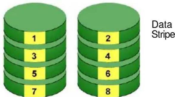
Physical Drives
The logical drive's data capacity equals the capacity of the smallest physical drive times the number of physical drives. For example, one 100 GB and three 120 GB drives will form a 400 GB (4 x 100 GB) logical drive instead of 460 GB.
If physical drives of different capacities are used, there will also be unused capacity on the larger drives.
RAID 0 logical drives on SuperTrak consist of one or more physical drives.
RAID 1 – Mirror
When a logical drive is mirrored, identical data is written to a pair of physical drives, while reads are performed in parallel. The reads are performed using elevator seek and load balancing techniques where the workload is distributed in the most efficient manner. Whichever drive is not busy and is positioned closer to the data will be accessed first.
With RAID 1, if one physical drive fails or has errors, the other mirrored physical drive continues to function. Moreover, if a spare physical drive is present, the spare drive will be used as the replacement drive and data will begin to be mirrored to it from the remaining good drive.
Figure 2. RAID 1 Mirrors identical data to two drives
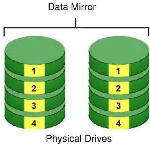
The logical drive's data capacity equals the smaller physical drive. For example, a 100 GB physical drive and a 120 GB physical drive have a combined capacity of 100 GB in a mirrored logical drive.
If physical drives of different capacities are used, there will be unused capacity on the larger drive.
RAID 1 logical drives on SuperTrak consist of two physical drives.
If you want a mirrored logical drive with more than two physical drives, see “RAID 1E – Enhanced Mirror” on page 230 and “RAID 10 – Mirror / Stripe” on page 233.
RAID 1E – Enhanced Mirror
RAID 1E offers the security of mirrored data provided by RAID 1 plus the added capacity of more than two physical drives. It also offers overall increased read/write performance plus the flexibility of using an odd number of physical drives. With RAID 1E, each data stripe is mirrored onto two physical drives. If one drive fails or has errors, the other drives continue to function, providing fault tolerance.
Figure 3. RAID 1E can mirror data over an odd number of drives
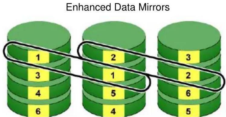
Physical Drives
The advantage of RAID 1E is the ability to use an odd number of physical drives, unlike RAID 1 and RAID 10. You can also create a RAID 1E Logical Drive with an even number of physical drives. However, with an even number of drives, you will obtain somewhat greater security with comparable performance using RAID 10.
RAID 1E logical drives consist of three or more physical drives. You can create an array with just two physical drives and specify RAID 1E. But the resulting array will actually be a RAID 1.
RAID 5 – Block Striping with Distributed Parity
RAID 5 organizes block data and parity data across the physical drives. Generally, RAID Level 5 tends to exhibit lower random write performance due to the heavy workload of parity recalculation for each I/O. RAID 5 is generally considered to be the most versatile RAID level. It works well for file, database, application and web servers.
Figure 4. RAID 5 stripes all drives with data and parity information
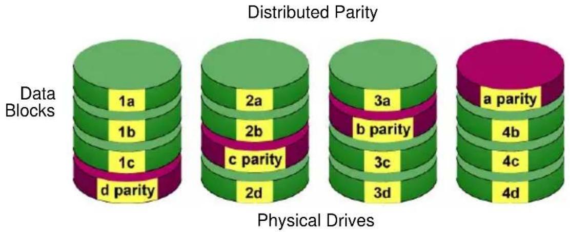
The capacity of a RAID 5 logical drive equals the smallest physical drive times the number of physical drives, minus one. Hence, a RAID 5 logical drive with four 100 GB physical drives will have a capacity of 300 GB. A RAID 5 logical drive with two 120 GB physical drives and one 100 GB physical drive will have a capacity of 200 GB.
RAID 5 is generally considered to be the most versatile RAID level.
A RAID 5 on SuperTrak consists of 3 to 16 physical drives.
RAID 6 – Block and Double Parity Stripe
RAID level 6 stores dual parity data is rotated across the physical drives along with the block data. A RAID 6 logical drive can continue to accept I/O requests when any two physical drives fail.
Figure 5. RAID 6 stripes all drives with data and dual parity
Double Distributed (P and Q) Parity
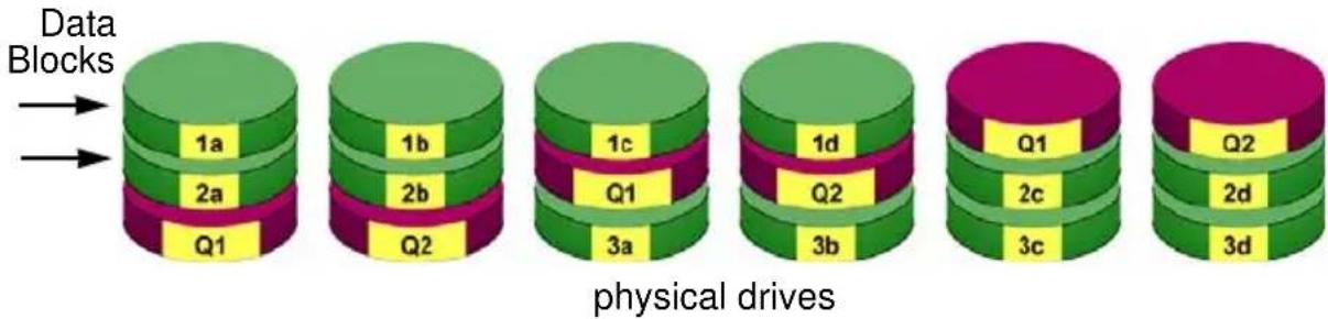
The total capacity of a RAID 6 logical drive is the smallest physical drive times the number of physical drives, minus two.
Hence, a RAID 6 logical drive with (7) 100 GB physical drives will have a capacity of 500 GB. A RAID 6 logical drive with (4) 100 GB physical drives will have a capacity of 200 GB.
RAID 6 becomes more capacity efficient in terms of physical drives as the number of physical drives increases.
RAID 6 provides double fault tolerance. Your logical drive remains available when up to two physical drives fail.
RAID 6 is generally considered to be the safest RAID level.
A RAID 6 on SuperTrak consists of 4 to 16 physical drives.
RAID 10 – Mirror / Stripe
Mirror/Stripe combines both of the RAID 0 and RAID 1 logical drive types. RAID 10 is similar though not identical to RAID 0+1. It can increase performance by reading and writing data in parallel while protecting data with duplication. The data on one drive pair is mirrored together, then striped over a second drive pair.
Figure 6. RAID 10 takes a data mirror on one drive pair and stripes it over a second drive pair
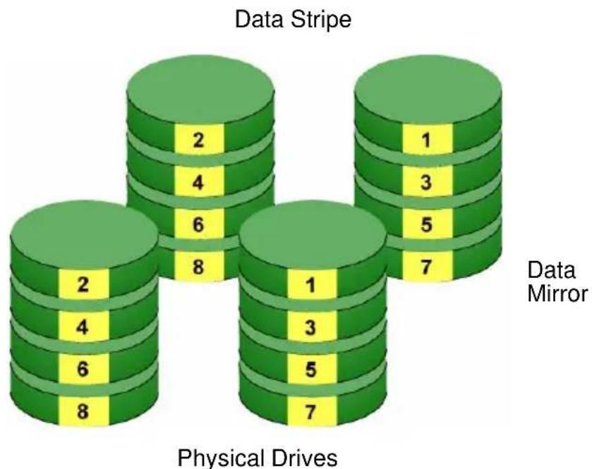
The data capacity RAID 10 logical drive equals the capacity of the smallest physical drive times the number of physical drives, divided by two.
In some cases, RAID 10 offers double fault tolerance, depending on which physical drives fail.
RAID 10 arrays require an even number of physical drives and a minimum of four.
For RAID 10 characteristics with an odd number of physical drives, use RAID 1E. See page 230.
RAID 50 – Striped Distributed Parity
RAID 50 combines both RAID 5 and RAID 0 features. Data is striped across physical drives as in RAID 0, and it uses distributed parity as in RAID 5. RAID 50 provides data reliability, good overall performance, and supports larger volume sizes.
Figure 7. RAID 50 is a combination of RAID 5 and RAID 0
![graph TD A["Data Stripe"] --> B["Distributed Parity"] B --> C1["1: green cylinder"] B --> C2["5: green cylinder"] B --> C3["parity"] C1 --> D1["green cylinder"] C2 --> D2["green cylinder"] C3 --> D3["green cylinder"] D1 --> E1["Axle 1"] D2 --> E2["parity"] D3 --> E3["parity"] E1 --> F1["green cylind…](/content/2026/05/785299/images/3d9c519a8d8730acd1587267f851b680bcd72dae55f15ec815752b741460c0a5.jpg)
The data capacity RAID 50 logical drive equals the capacity of the smallest physical drive times the number of physical drives, minus two.
RAID 50 also provides very high reliability because data is still available even if multiple physical drives fail (one in each axle). The greater the number of axles, the greater the number of physical drives that can fail without the RAID 50 logical drive going offline.
| Component Minimum | Maximum | |
| Number of Axles 2 16 | ||
| Physical Drives per Axle 3 16 | ||
| Physical Drives per Logical Drive 6 | 256 |
RAID 50 Axles
When you create a RAID 50, you must specify the number of axles. An axle refers to a single RAID 5 logical drive that is striped with other RAID 5 logical drives to make RAID 50. An axle can have from 3 to 16 physical drives, depending on the number of physical drives in the logical drive.
The chart below shows RAID 50 logical drives with 6 to 16 physical drives, the available number of axles, and the resulting distribution of physical drives on each axle.
| RAID 50 Logical Drive | ||
| No. of Drives No. of Axles Drives per Axle | ||
| 6 | 2 | 3 |
| 7 | 2 | 3 |
| 8 | 2 | 4 |
| 9 | 2 | 4 |
| 3 | 3 | |
| 10 2 5,5 | ||
| 3 | 3 | |
| 11 25,6 | ||
| 3 | 3 | |
| 12 2 6,6 | ||
| 3 | 4 | |
| 4 3,3,3,3 | ||
| 13 2 6,7 | ||
| 3 | 4 | |
| 4 3,3,3,4 | ||
| 14 2 7,7 | ||
| 3 | 4 | |
| 4 3,3,4,4 | ||
| 15 2 7,8 | ||
| 3 | 5 | |
| 4 3,4,4,4 | ||
| 5 3,3,3,3,3 | ||
| 16 2 8,8 | ||
| 3 | 5 | |
| 4 4,4,4,4 | ||
| 5 3,3,3,3,4 | ||
RAID 60 – Striping of Double Parity
RAID 60 combines both RAID 6 and RAID 0 features. Data is striped across disks as in RAID 0, and it uses double distributed parity as in RAID 6. RAID 60 provides data reliability, good overall performance and supports larger volume sizes.
Figure 8. RAID 60 is a combination of RAID 6 and RAID 0
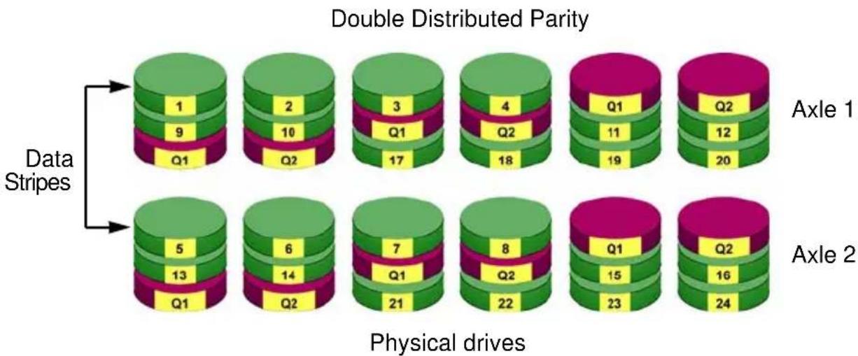
The total capacity of a RAID 60 logical drive is the smallest physical drive times the number of physical drives, minus four.
RAID 60 also provides very high reliability because data is still available even if multiple physical drives fail (two in each axle). The greater the number of axles, the greater the number of physical drives that can fail without the RAID 60 logical drive going offline.
| Component Minimum | Maximum | |
| Number of Axles 2 16 | ||
| Physical Drives per Axle 4 16 | ||
| Physical Drives per Logical Drive 8 | 256 |
RAID 60 Axles
When you create a RAID 60, you must specify the number of axles. An axle refers to a single RAID 6 logical drive that is striped with other RAID 6 logical drives to make RAID 60. An axle can have from 4 to 16 physical drives, depending on the number of physical drives in the logical drive.
The chart below shows RAID 60 logical drives with 8 to 20 physical drives, the available number of axles, and the resulting distribution of physical drives on each axle.
| RAID 60 Logical Drive | ||
| No. of Drives No. of Axles Drives per Axle | ||
| 8 | 2 | 4 |
| 9 | 2 | 4 |
| 10 2 5,5 | ||
| 11 25,6 | ||
| 12 2 6,6 | ||
| 3 | 4 | |
| 13 2 6,7 | ||
| 3 | 4 | |
| 14 2 7,7 | ||
| 3 | 4 | |
| 15 2 7,8 | ||
| 3 | 5 | |
| 16 2 8,8 | ||
| 3 | 5 | |
| 4 4,4,4,4 | ||
| 17 2 8,9 | ||
| 3 | 5 | |
| 4 4,4,4,5 | ||
| 18 2 9,9 | ||
| 3 | 6 | |
| 4 4,4,5,5 | ||
| 19 2 9,10 | ||
| 3 | 6 | |
| 4 4,5,5,5 | ||
| 20 2 10,10 | ||
| 3 | 6 | |
| 4 5,5,5,5 | ||
| 5 4,4,4,4,4 | ||
Choosing a RAID Level
There are several issues to consider when choosing the RAID Level for your logical drive. The following discussion summarizes some advantages, disadvantages and applications for each choice.
RAID 0
| Advantages Disadvantages | |
| Implements a striped logical drive, the data is broken down into blocks and each block is written to a separate physical driveI/O performance is greatly improved by spreading the I/O load across many channels and drivesNo parity calculation overhead is involved | Not a true RAID because it is not fault-tolerantThe failure of just one drive will result in all data in an logical drive being lostShould not be used in mission critical environments |
Recommended applications for RAID 0:
- I m a g e E d i t i n g
• Pre-Press Applications - Any application requiring high bandwidth
RAID 1
| Advantages Disadvantages | |
| Simplest RAID storage subsystem designCan increase read performance by processing data requests in parallel since the same data resides on two different drives | Very high physical drive overhead – uses only 50% of total capacity |
Recommended applications for RAID 1:
• Accounting/Financial
- Pay roll
- Any application requiring very high availability
RAID 1E
| Advantages Disadvantages | |
| Implemented as a mirrored logical drive whose segments are RAID 0 logical drivesHigh I/O rates are achieved thanks to multiple stripe segmentsCan use an odd number of physical drives | Very high physical drive overhead – uses only 50% of total capacity |
Recommended Applications for RAID 1E
- Imaging applications
- Database servers
- General fileserver
RAID 5
| Advantages Disadvantages | |
| High Read data transaction rateMedium Write data transaction rateGood aggregate transfer rateMost versatile RAID level | Physical drive failure has a medium impact on throughput |
Recommended applications for RAID 5:
- File and Application servers
- WWW, E-mail, and News servers
- Intranet servers
RAID 6
| Advantages Disadvantages | |
| High Read data transaction rateMedium Write data transaction rateGood aggregate transfer rateSafest RAID level | High physical drive overhead – equivalent of two drives used for paritySlightly lower performance than RAID 5 |
Recommended applications for RAID 6:
• Accounting/Financial
- Database servers
- Any application requiring very high availability
RAID 10
| Advantages Disadvantages | |
| Implemented as a mirrored logical drive whose segments are RAID 0 logical drivesHigh I/O rates are achieved thanks to multiple stripe segments | Very high physical drive overhead – uses only 50% of total capacity |
Recommended applications for RAID 10:
- Imaging applications
- Database servers
- General fileserver
RAID 50
| Advantages Disadvantages | |
| High Read data transaction rateGood write data transaction rateVery good aggregate transfer rateMost versatile RAID level | Physical drive failure has a moderate impact on throughput |
Recommended applications for RAID 50:
- File and Application Servers
- Transaction Processing
• Office applications with many users accessing small files
RAID 60
| Advantages Disadvantages | |
| High Read data transaction rateMedium Write data transaction rateGood aggregate transfer rateSafest RAID level | High disk overhead – equivalent of two drives used for paritySlightly lower performance than RAID 50 |
Recommended Applications for RAID 60:
• Accounting and Financial
- Database servers
- Any application requiring very high availability
Choosing Stripe Block Size
You set the stripe block size, also called block size, when you create a logical drive. With SuperTrak, the choices are 64 KB, 128 KB, 256 KB, 512 KB, and 1024 KB. 64 KB is the default.
Your choice will directly affect performance. There are two issues to consider when choosing the stripe block size.
- Choose a stripe block size equal to or smaller than the smallest cache buffer found on any physical drive in your logical drive.
A larger value slows the logical drive down because physical drives with smaller cache buffers need more time for multiple accesses to fill their buffers.
- If your data retrieval consists of fixed-size data blocks, such as some database and video applications, choose that data block size as your stripe block size.
Generally speaking, email, POS, and webservers prefer smaller stripe block sizes. Video and database applications prefer larger stripe block sizes.
See “Creating a Logical Drive” on page 96 and “Creating a Logical Drive” on page 165, and “Creating a Disk Array – Advanced Configuration” on page 161.
Choosing Sector Size
You set the sector size when you create a logical drive. With SuperTrak, the choices are 512 B, 1 KB, 2 KB, and 4 KB. 512 B is the default.
A sector is the smallest addressable area on a physical drive. Sector Size refers to the size of sector measured by the number of bytes of data it can hold. The most common sector size is 512 bytes (512 B). A smaller sector size results in a more efficient use of a physical drive's capacity. 512 B is the default sector size for logical drives on SuperTrak.
The number of usable sectors is limited by the addressing method of the computer's operating system:
- Windows XP (32-bit) support 10-bit logical bit addressing (LBA), so with 512 B sectors, they can only support up to 2 terabytes (TB) of data storage capacity. To increase the capacity, you must use larger sectors. See “2 TB Limitation” on page 245.
- Windows XP (64-bit), Windows Server 2003 and 2008, and Windows Vista support 64-bit LBA, so they are not affected by this limitation. For these OSes, always choose the default 512 B sector size.
- Linux operating systems with the 2.4 kernel do not support variable sector sizes. For these OSes, always choose the default 512 B sector size.
- Linux operating systems with the 2.6 kernel support 64-bit LBA. For these OSes, always choose the default 512 B sector size.
See “Creating a Logical Drive” on page 96 and “Creating a Logical Drive” on page 165, and “Creating a Disk Array – Advanced Configuration” on page 161.
2 TB Limitation
If your Host PC runs Windows XP (32-bit), and you want to create logical drives larger than 2 TB, you must choose a sector size larger than 512 B when you create the logical drive. The table on the next page correlates sector size with logical drive capacity.
| Logical Drive Size Sector Size | |
| 8 to 16 TB 4096 | bytes (4 KB) |
| 4 to 8 TB 2048 | bytes (2 KB) |
| 2 to 4 TB 1024 | bytes (1 KB) |
| 0 to 2 TB 512 | bytes (512 B) |
Also see "Ranges of Disk Array Expansion" on page 253.
Choosing Cache Policy
As it is used with SuperTrak, the term cache refers to any of several kinds of high-speed, volatile memory that hold data moving from your computer to the physical drives or vice-versa. Cache is important because it can read and write data much faster than a physical drive. There are read caches, which hold data as it is read from a physical drive; and write caches, which hold data as it is written to a physical drive.
In order to tune the cache for best performance in different applications, user-adjustable settings are provided. Cache settings are made in conjunction with logical drives:
- When you create a logical drive. See “Creating a Logical Drive” on page 96 and “Creating a Logical Drive” on page 165, and “Creating a Disk Array – Advanced Configuration” on page 161.
- On an existing logical drive. See “Changing Logical Drive Settings” on page 98 or page 174.
Read Cache Policy
- Read Cache – The read cache is enabled.
- Read Ahead – The read cache and the read-ahead feature are enabled. Read-ahead anticipates the next read and performs it before the request is made. Can increase read performance.
- Forced Read Ahead – Continues reading ahead even when the next read cannot be logically anticipated. Can increase read performance.
- No Cache – The read cache is disabled.
Write Cache Policy
- Write Back – Data is written first to the cache, then to the logical drive. Better performance. Requires a cache backup battery to protect data in the cache from a sudden power failure.
- Write Through – Data is written to the cache and the logical drive at the same time. Safer.
- Adaptive Writeback Cache – Data is written first to the cache, then to the logical drive. Changes the write cache settings while the cache backup battery is offline.
When all of the following conditions occur:
• The logical drive write policy is set to Write Back
• The Adaptive Writeback Cache feature is enabled
• The cache backup battery goes offline
The write policy automatically changes to Write Through. When the battery comes back online, the write policy automatically changes back to Write Back.
Capacity Coercion
This feature is designed for fault-tolerant logical drives (RAID 1, 1E, 5, 6, 10, 50, and 60). It is generally recommended to use physical drives of the same size in your disk arrays. When this is not possible, physical drives of different sizes will work but the system must adjust for the size differences by reducing or coercing the capacity of the larger drives to match the smaller ones. With SuperTrak, you can choose to enable Capacity Coercion and any one of four methods.
Enable Capacity Coercion and choose the Method in the Controller Settings menu. See “Making Controller Settings” on page 144. The choices are:
- GBTruncate – (Default) Reduces the useful capacity to the nearest 1,000,000,000-byte boundary.
- 10GBTruncate – Reduces the useful capacity to the nearest 10,000,000,000-byte boundary.
- GRPRounding – Uses an algorithm to determine how much to truncate. Results in the maximum amount of usable drive capacity.
- TableRounding – Applies a predefined table to determine how much to truncate.
Capacity Coercion also affects a replacement drive used in a disk array. Normally, when an physical drive fails, the replacement drive must be the same capacity or larger. However, the Capacity Coercion feature permits the installation of a replacement drive that is slightly smaller (within 1 gigabyte) than the remaining working drive. For example, the remaining working drives can be 80.5 GB and the replacement drive can be 80.3, since all are rounded down to 80 GB. This permits the smaller drive to be used.
Without Capacity Coercion, the controller will not permit the use of a replacement physical drive that is slightly smaller than the remaining working drive(s).
Initialization
Initialization is highly recommended for logical drives when they are created from a disk array. Initialization sets all data bits in the logical drive to zero. The action is useful because there may be residual data on the logical drives left behind from earlier configurations. You can also perform an Initialization on an existing logical drive.

Warning
When you initialize a logical drive, all the data the logical drive will be lost. Backup any important data before you initialize a logical drive.
There are three options for logical drive initialization:
- Full – Overwrites all data bits on the logical drive. Can take some time for larger logical drives
- Quick – Overwrites the data bits on the first and last blocks of logical drive. Takes only seconds.
- None – No initialization. Not recommended.
See “Creating a Logical Drive” on page 96 and “Creating a Logical Drive” on page 165, and “Creating a Disk Array – Advanced Configuration” on page 161, and “Initializing a Logical Drive” on page 175.
Hot Spare Drive
A hot spare is a physical drive that is available to a disk array but not actually a part of it. If you designate a spare drive, SuperTrak will replace a failed physical drive in a disk array with the hot spare drive automatically. See “Creating a Spare Drive” on page 99 or page 179.
Compared to the failed drive, the replacement drive must be:
• The same media type, HDD or SDD
• Equal or larger capacity
There are two types of hot spare drive:
- Global – An unassigned physical drive available to any logical drive on the Host PC.
- Dedicated – An unassigned physical drive that can only be used by a specified logical drive.
There is another property you can assign to a hot spare drive:
- Revertible – A revertible spare drive will return to spare status when the failed drive is replace with a new drive. See “Transition” on page 256.
Whenever possible, having a spare drive for your RAID system is good protection against physical drive failure. Even though the spare drive is assigned to a disk array, the rebuild operation is said to apply to a logical drive.
If you do not have a spare drive, but the Auto Rebuild function is enabled, the critical disk array will begin to rebuild as soon as you replace the failed physical drive with an unconfigured physical drive of equal or greater size. See “Making Background Activity Settings” on page 137.
Partition and Format the Logical Drive
Like any other type of fixed disk media in your system, a RAID logical drive must also be partitioned and formatted before use. Use the same method of partitioning and formatting on an logical drive as you would any other fixed disk.
See "Appendix A: Partition and Format" on page 285.
RAID Level Migration
To migrate a disk array is to do one or both:
- Change its RAID level
- Increase the number of physical drives (sometimes called expansion)
On SuperTrak, RAID level migration is performed on the disk array but it applies to the logical drives. Migration takes place on an existing Functional disk array without disturbing the existing data. While the disk array is migrating, you can
access the data as before. When migration is complete, your disk array will have a different RAID level and/or a larger capacity.
In most cases, you must add one or more physical drives during the migration process. You can never reduce the number of physical drives.
The tables below show the migration options for a source logical drive according to its RAID level. The available target RAID levels are shown with their requirements.
You must use WebPAM PRO to migrate a disk array. See “Migrating a Disk Array” on page 167.
RAID 0
A RAID 0 source logical drive can migrate to the following target logical drives:
| Target Requirements | |
| RAID 0 Add physical drives. | |
| RAID 1 2 physical drives only.Only a single-drive RAID 0 can migrate to RAID 1 by adding 1 physical drive. | |
| RAID 1E 3 or more physical drives. | |
| RAID 5 3 physical drives minimum, 16 maximum.RAID 0 must have less than 16 physical drives. | |
| RAID 6 4 physical drives minimum, 16 maximum. | |
| RAID 10 4 physical drives minimum.Even number of physical drives. | |
| RAID 50 6 physical drives minimum, 16 per axle maximum. | |
| RAID 60 8 physical drives minimum, 16 per axle maximum. |
RAID 1
A RAID 1 Source logical drive can migrate to the following Target logical drives:
| Target Requirements | |
| RAID 0 None. | |
| RAID 1E 3 or more physical drives. | |
| RAID 5 3 physical drives minimum, 16 maximum.RAID 1 must have less than 16 physical drives. | |
| RAID 10 4 physical drives minimum.Even number of physical drives. | |
| RAID 50 6 physical drives minimum, 16 per axle maximum. | |
RAID 1E
A RAID 1E Source logical drive can migrate to the following Target logical drives:
| Target Requirements | |
| RAID 0 None. | |
| RAID 1E Add physical drives. | |
| RAID 5 3 physical drives minimum, 16 maximum.RAID 1E must have less than 16 physical drives. | |
| RAID 10 4 physical drives minimum.Even number of physical drives. | |
| RAID 50 6 physical drives minimum, 16 per axle maximum. | |
RAID 5
A RAID 5 Source logical drive can migrate to the following Target logical drives:
| Target Requirements | |
| RAID 0 None. | |
| RAID 1E None. | |
| RAID 5 Add physical drives. 16 maximum. | |
| RAID 6 4 physical drives minimum, 16 maximum. | |
| RAID 10 4 physical drives minimum.Even number of physical drives. | |
| RAID 50 6 physical drives minimum, 16 per axle maximum. | |
| RAID 60 8 physical drives minimum, 16 per axle maximum. | |
RAID 6
A RAID 6 Source logical drive can migrate to the following Target logical drives:
| Target Requirements | |
| RAID 6 Add physical drives. 16 maximum. | |
| RAID 60 8 physical drives minimum, 16 per axle maximum. |
RAID 10
A RAID 10 Source logical drive can migrate to the following Target logical drives:
| Target Requirements | |
| RAID 0 None. | |
| RAID 1E None. | |
| RAID 5 3 physical drives minimum, 16 maximum.RAID 10 must have less than 16 physical drives. | |
| RAID 6 4 physical drives minimum, 16 maximum.RAID 10 must have less than 16 physical drives. | |
| RAID 10 Add | physical drives.Even number of physical drives. |
| RAID 50 6 physical drives minimum, 16 per axle maximum. | |
| RAID 60 8 physical drives minimum, 16 per axle maximum. | |
RAID 50
A RAID 50 Source logical drive can migrate to the following Target logical drives:
| Target Requirements | |
| RAID 0 None. | |
| RAID 1E None. | |
| RAID 5 16 physical drives maximum.RAID 50 must have less than 16 physical drives. | |
| RAID 6 16 physical drives maximum.RAID 50 must have less than 16 physical drives. | |
| RAID 10 Even number of physical drives. | |
| RAID 50 Add physical drives. 16 per axle maximum. | |
| RAID 60 8 physical drives minimum, 16 per axle maximum. | |
RAID 60
A RAID 60 Source logical drive can migrate to the following Target logical drives:
| Target Requirements | |
| RAID 6 16 physical drives maximum. RAID 60 must have less than 16 physical drives. | |
| RAID 60 Add physical drives. 16 per axle maximum. |

Important
- The Target disk array may require more physical drives than the Source disk array
- If the Target disk array requires an EVEN number of physical drives but the Source disk array has an ODD number, ADD a physical drive as part of the migration process
- You cannot reduce the number of physical drives in your disk array, even if the Target disk array requires fewer physical drives than the Source disk array
- RAID 1 (mirroring) works with two drives only. Only a single-drive RAID 0 disk array can migrate to RAID 1. Other RAID Levels use too many drives to migrate
- You cannot migrate a disk array when it is Critical or performing activities such as Synchronizing, Rebuilding, and PDM
- For RAID 6 or RAID 60, you can only migrate between these two RAID levels. Destination RAID 60 axles can have up to 16 physical drives. Other limitations might apply
Ranges of Disk Array Expansion
The Windows XP (32-bit) operating systems support a 10-byte LBA format. As a result, these OSes can only recognize 4 billion addresses. If you create a logical drive using the default 512 B sector size, the logical drive will be limited to 2 TB of data, even if there is more space available on your physical drives.
This limitation does not apply to Windows XP (64-bit), 2003 Server, Vista, and Linux OSes with the 2.6 kernel. Linux OSes with the 2.4 kernel do not support variable sector sizes, therefore you cannot apply the solution described here to those OSes.
Note that once you create your logical drive, you cannot change the size of the sectors. Nor can you increase the number of address blocks that the OS recognizes.
You can direct WebPAM PRO to expand a logical drive beyond the maximum expansion size. When the expansion is finished:
- WebPAM PRO will show the logical drive in the desired size.
- Your operating system might show the logical drive at the maximum size listed in the table below.
• Additional capacity might appear as unpartitioned and unformatted.
| Current LD Size | Maximum LD Expansion Size | Sector Size |
| 8 to 16 TB 16 TB | 4096 bytes | |
| 4 to 8 TB 8 TB | 2048 bytes | |
| 2 to 4 TB 4 TB | 1024 bytes | |
| up to 2 TB 2 TB | 512 bytes |
At this point, you have the choice of:
- Format the unpartitioned/unformatted capacity as a second logical drive
- Delete the existing disk array and create a new one in the desired size
Delete and Recreate
If you require a logical drive larger than the maximum expansion size:
- Backup the data from the current logical drive.
- Delete the current logical drive.
See "Deleting a Logical Drive" on page 98 or page 166.
- Create a new logical drive with the desired capacity.
See "Creating a Logical Drive" on page 96 or page 165.
- Restore the data to the new logical drive.
Media Patrol
Media Patrol is a routine maintenance procedure that checks the magnetic media on each physical drive. Media Patrol checks all physical drives assigned to disk arrays and on spare drives. Media Patrol does not check unconfigured drives.
Unlike Synchronization and Redundancy Check, Media Patrol is concerned with the condition of the media itself, not the data recorded on the media. If Media Patrol encounters a critical error, it triggers PDM if PDM is enabled.
You can run Media Patrol:
• From the subsystem. See page 138.
- Directly on a disk array. See page 169.
Predictive Data Migration (PDM)
Predictive Data Migration (PDM) is the migration of data from the suspect physical drive to a spare drive, similar to Rebuilding a Logical Drive. But unlike Rebuilding, PDM constantly monitors your physical drives and automatically copies your data to the spare drive before the suspect drive fails and your Logical Drive goes Critical. See “Running PDM” on page 138 and “Running PDM on a Disk Array” on page 169.
After the data is copied from the suspect drive, the controller marks the suspect drive with a Stale configuration and a PFA error.
You can clear the Stale configuration and PFA error and put the physical drive back into service. See “Clearing Stale and PFA Conditions” on page 152 or page 269. In some cases, however, you might remove the physical drive for repair or replacement.
PDM Triggers
The following actions trigger PDM:
• A physical drive with unhealthy status (see below)
• Media Patrol finds a disk critical error*
- You initiate PDM manually
*PDM also counts the number of media errors reported by Media Patrol.
A physical drive becomes unhealthy when:
• A SMART error is reported
- The bad sector remapping table fills to the specified level
Because data would be lost if written to a bad sector, when a bad sector is detected, the physical drive creates a map around it. These maps are saved in
the bad sector remapping table, which has a capacity of 512 reassigned blocks and 1024 error blocks.
When the table fills to a specified percentage of its capacity, PDM triggers a migration of data from the suspect drive (the physical drive with the bad sectors) to a spare drive.
During data migration, you will have access to the logical drive but it will respond more slowly to read/write tasks because of the additional operation. The time required for data migration depends on the size of the physical drive.
See "Making Background Activity Settings" on page 137.
Transition
The Transition feature enables you to specify “permanent” spare drives for your SuperTrak controller. Transition is the process of replacing a revertible spare drive that is currently part of a disk array with an unconfigured physical drive or a non-revertible spare. The revertible spare drive returns to its original status.
Transition happens automatically when the following sequence of events takes place:
- You create a revertible spare drive. "Creating a Spare Drive" on page 179.
- One of the physical drives assigned to your disk array fails and the array becomes degraded and the logical drive goes critical.
- The SuperTrak controller automatically rebuilds your array to the revertible spare drive and the array becomes functional again.
- You replace the failed physical drive with a new physical drive of equal or greater capacity.
- The SuperTrak controller automatically transitions (moves) the data from the revertible spare to the new physical drive.
- The new physical drive becomes part of the array and the revertible spare drive returns to its original spare status.
Transition happens manually when you specify a different unconfigured physical drive to transition (move) the data from the revertible spare drive.
Drive Failure and Automatic Rebuild
In the example below, there is a two-drive RAID 1 disk array.
- The physical drives in channels 1 and 2 belong to the disk array.
- The physical drive in channel 3 is unconfigured.
- The physical drive in channel 4 is a revertible spare drive.
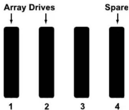
The physical drive in channel 2 fails. The disk array becomes degraded and its logical drives go critical. The SuperTrak controller automatically rebuilds the disk array using the revertible spare drive, the physical drive in channel 4.
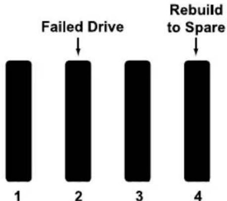
When the rebuild is finished, the disk array and logical drives are OK again.
• The physical drives in channels 1 and 4 belong to the disk array.
- The physical drive in channel 2 has failed and is unusable.
- The physical drive in channel 3 is unconfigured.
Note that there is no spare drive at this moment.

Automatic Transition
At this juncture, you would replace the failed drive in channel 2 with a new drive of the same or greater capacity.
When the SuperTrak controller detects the new drive in channel 2, it will:
- Transition the data from the drive in channel 4 to the drive in channel 2.
- Return the drive in channel 4 to spare status.
When the Transition is finished:
- The physical drives in channels 1 and 2 belong to the disk array.
- The physical drive in channel 3 is still unconfigured.
- The physical drive in channel 4 is a revertible spare drive.
The original configuration is restored.
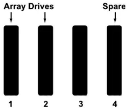
Manual Transition
Manual transition requires an unassigned physical drive.
The example below is the same two-drive RAID 1 disk array as before.
- The physical drives in channels 1 and 2 belong to the disk array.
- The physical drive in channel 3 is unconfigured.
- The physical drive in channel 4 is a revertible spare drive.
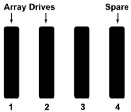
The physical drive in channel 2 fails. The disk array becomes degraded and its logical drives go critical. The SuperTrak controller automatically rebuilds the disk array using the spare drive, the physical drive in channel 4.
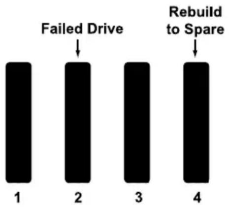
As we saw in the example of Automatic Transition, if you replace the failed physical drive in channel 2, the SuperTrak controller would transition the data from the physical drive in channel 4 to the new drive in channel 2.
But if you wanted to use a different physical drive in your array, such as the unassigned drive in channel 3, you would run the Transition function manually.
When the Manual Transition is finished:
- The physical drives in channels 1 and 3 belong to the disk array.
- The physical drive channel 2 is still failed and unusable.
- The physical drive in channel 4 is a revertible spare drive.

At this point, after running the Manual Transition, you would replace the failed drive in channel 2. The replacement drive in channel 2 will remain unconfigured until you assign it to a disk array or as a spare.
Chapter 8: Troubleshooting
• Problem Reports from SuperTrak
- Buzzer (page 261)
- LEDs (page 261)
• B I O S ( p a g e 2 6 3 )
- Problems Reported in WebPAM PRO (page 265)
• Critical & Offline Logical Drives (page 267)
• Salvaging Physical Drives (page 269)
- Rebuilding a Disk Array Automatically (page 270)
- Rebuilding a Disk Array Manually (page 270)
- Rebuilding with WebPAM PRO (page 270)
- Rebuilding with SuperBuild (page 271)
• Recovering from a Blank Screen (page 272)
- Cache Battery Does Not Charge (page 272)
Problems Reported by SuperTrak
The SuperTrak EX Controller provides both audible and visual indicators to alert you to a problem.
Buzzer
The buzzer sounds to inform you that your RAID system needs attention. But the buzzer does not specify the condition. When a continuous tone sounds, there are multiple alarm patterns sounding at the same time.
When the buzzer sounds, take the following actions:
- Check your disk arrays and logical drives.
- Check the Event Log. See page 103 or page 115.
LEDs
If your system is configured with Global LEDs or Direct LEDs, they will indicate when a problem is present. Use the SuperBuild utility or WebPAM PRO to further diagnose and correct the problem.
Global LED Display
Global LEDs glow in response to Logical Drive status.
| LED Logical Drive Status | |
| Dark System off | |
| Green Normal | |
| Amber Logical Drive Critical | |
| Red Logical Drive Offline |
Direct LED Display
Direct LEDs, glow and blink in response to the SuperTrak's firmware status.
| Fault LED | Activity LED | Firmware Status |
| OFF OFF | No physical drive | |
| ON ON | Unconfigured physical drive | |
| OFF ON | Configured physical drive – Status OK | |
| ON ON | Configured physical drive – Status Not OK | |
| OFF ON | Global spare drive – Status OK | |
| ON ON | Physical drive – Status Dead | |
| ON ON | Stale condition | |
| Blink ON | Rebuilding | |
| OFF Blink Activity | ||
| Blink ON | Locate physical drive | |
| Blink | ON Locate logical drive | |
| Blink | ON Locate disk array |
BIOS
The problem is first reported in the SuperTrak BIOS screen when you boot your PC or server, as shown below.
Figure 1. SuperTrak BIOS screen, logical drive critical

If the SuperTrak BIOS detects an Critical logical drive, the BIOS reports the condition but allows the booting process of the Host PC to continue.
Choose a Management application:
- Press Ctrl-S at the BIOS screen to open the SuperBuild utility.
- Allow your OS to boot, then open WebPAM PRO.
Figure 2. SuperTrak BIOS screen, logical drive offline
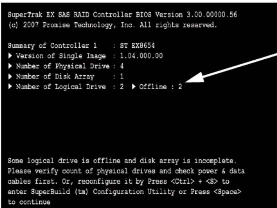
If the SuperTrak BIOS detects an Offline logical drive, the BIOS reports the condition and temporarily halts the booting process of the Host PC.
Choose a Management application:
- Press Ctrl-S to open the SuperBuild utility.
- Press the Space bar, allow your OS to boot, then open WebPAM PRO.
Problems Reported in WebPAM PRO
Opening WebPAM PRO
If WebPAM PRO is not running, do the following actions:
- Open WebPAM PRO.
See "Logging into WebPAM PRO" on page 109 for more information.
- Click the Subsystem icon in Tree View.
- Click the Enclosures icon and its subordinate icons.
- Click the Disk Arrays icon and its subordinate icons.
What to Look For
When a logical drive goes critical or offline, WebPAM PRO reports the condition in the following ways:
• Displays yellow !s red Xs in Tree View (below)
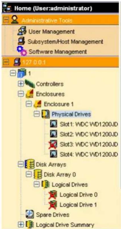
- Sends email messages, per your configuration
- Displays popup messages, per your configuration (below)
7 New Events Last Event: 29, DA 0, Major, May 12, 2005 13:28:02 Logical drive has been set to critical
- Keeps a record in the Event Log (below)
| # | Device | Event ID | Severity | Time √ | Description |
| 34 | DA 0 | 0x000F0001 | Info | May 12, 2005 13:28:47 | Rebuild is completed |
| 33 | LD 0 | 0x00090006 | Info | May 12, 2005 13:28:47 | Rebuild marks the logical drive synchronized upon rebuild completion |
| 32 | LD 0 | 0x00090002 | Info | May 12, 2005 13:28:47 | Logical drive has been placed online |
| 31 | DA 0 | 0x000F0000 | Info | May 12, 2005 13:28:03 | Rebuild is started |
| 30 | PD 5 | 0x000D000B | Info | May 12, 2005 13:28:02 | Physical Disk has been removed |
| 29 | LD 0 | 0x00090004 | Major | May 12, 2005 13:28:02 | Logical drive has been set to critical |
| 28 | PD 5 | 0x000D001A | Major | May 12, 2005 13:28:02 | Physical Disk is marked as DEAD due to removal |
| 27 | Spare 0 | 0x001D0001 | Info | May 12, 2005 02:00:26 | Spare check completed successfully on the given spare drive |
| 26 | Spare 1 | 0x001D0001 | Info | May 12, 2005 02:00:26 | Spare check completed successfully on the given spare drive |
| 25 | Spare 0 | 0x001D0000 | Info | May 12, 2005 02:00:26 | Spare check started on the given spare drive |
Critical & Offline Logical Drives
A fault-tolerant logical drive—RAID 1, 1E, 5, 6, 10, 50, or 60—goes critical when a physical drive is removed or fails. Due to the fault tolerance of the logical drive, the data is still available and online. However, once the logical drive goes critical, the logical drive has lost its fault tolerance, and performance may be adversely affected.
If the fault was caused by a failed physical drive, the failed drive must be replaced in order for the disk array to rebuild and restore the logical drives on the array to normal or OK status.
If your fault-tolerant logical drive—RAID 1, 1E, 5, 6, 10, 50, or 60—goes offline, contact Technical Support. See page 277.

Warning
Take no further corrective action until you have consulted with Technical Support. See page 277.
A non-fault tolerant logical drive—RAID 0—goes offline when a physical drive is removed or fails. Since the logical drive is not fault tolerant, the data stored in the logical drive is no longer accessible.
If one physical drive fails, all of the data on the RAID 0 logical drive is lost. You must replace the failed drive. Then, if the logical drive had more than one physical drive, delete the logical drive and re-create it. Restore the data from a backup source.
Finding the Failed Drive in SuperBuild
To identify a failed physical drive:
- In the Main Menu, highlight Physical Drive Management and press Enter. The Physical Drive Management screen displays.
- Compare the list of physical drives on the screen against the actual physical drives attached to the SuperTrak controller.
Figure 3. Physical Drive Management screen
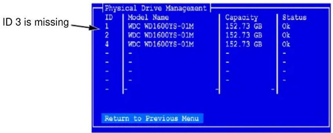
In the example above, there is no physical drive for ID 3. Assuming you installed a physical drive onto Channel 3 of the SuperTrak controller, this is the failed physical drive.
- Shut down the Host PC, open the case, check the power and data connections to each physical drive, correct any shortcomings, restart the Host PC and check in SuperBuild again.
Finding the Failed Drive in WebPAM PRO
To locate a failed or missing physical drive:
- Open WebPAM PRO.
See "Logging into WebPAM PRO" on page 109 for more information.
- Click the Subsystem icon in Tree View.
- Click the Enclosures icon.
- Click the Enclosure icon.
- Click the Physical Drives iron.
-
Examine the list of physical drives.
-
If a drive was present but is now missing, that is the failed drive. Check the power and data connections. If those are OK, you must replace the drive.
- If a drive is marked as PFA or Stale, that is the problem drive and you might be able to salvage the drive.
- If a drive is marked as Offline or Dead, that is the problem drive and you must replace it.
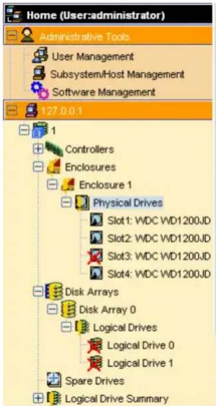
Salvaging Physical Drives
Physical drives can develop problems that make them unsuitable for service in a logical drive. These problems are reflected in the physical drive status:
• P F A – The physical drive has errors resulting in a prediction of failure
• Stale – Caused by obsolete array information on the physical drive
- Offline – The physical drive is present but set to Offline status
- Dead – Physical drive set down by the SuperTrak controller
WebPAM PRO has features to deal with PFA or Stale physical drives. An Offline or Dead physical drive cannot be salvaged and must be replaced.
Clearing Stale and PFA Conditions
To clear a Stale or PFA status from a physical drive:
-
Open WebPAM PRO. See "Logging into WebPAM PRO" on page 109 for more information.
-
Click the Subsystem icon in Tree View.
- Click the Enclosures icon.
- Click the Enclosure icon.
- Click the Physical Drives icon.
- Click a Physical Drive icon.
- In Management View, click the Clear tab.
- Click the Submit button.

Note
If a physical drive has both a Stale and a PFA condition, click the Submit button once to clear the Stale condition, then click again to clear the PFA condition.
Rebuilding a Disk Array Automatically
When you rebuild a disk array, you are actually rebuilding the data onto a replacement physical drive.
Normally, a Critical disk array automatically rebuilds itself using a designated spare drive. See “Creating a Spare Drive” on page 99 or page 179.
If you do not have a spare drive, the Critical disk array automatically rebuilds itself as soon as you remove the failed drive and insert a replacement drive. Note the replacement drive requirements, below.
During the rebuild:
- The alarm sounds two short beeps, repeated
- No warning icon displays over the disk array or logical drive icons
The disk array's Operational Status as OK, Rebuilding.
You can still read and write data to the logical drive. However, fault tolerance is lost until the disk array completes the rebuild.
After a successful rebuild:
- The alarm is silent
- The logical drive's Operational Status is OK
- The rebuilt physical drive Status LED displays steady green
Rebuilding a Disk Array Manually

Important
The replacement physical drive must be:
- The same media type, HDD or SDD, as the other drives in the array.
• Equal or larger capacity than the failed drive it replaces. - Free of any previous configuration data. See page 269.
If the Auto Rebuild function is disabled and no spare drives are available, you must initiate the procedure.
First, identify and replace the failed physical drive. See page 267 or page 268.
Then rebuild the disk array as described below.
Rebuilding with WebPAM PRO
To manually rebuild a disk array in WebPAM PRO:
-
Click the Subsystem icon in Tree View.
-
Click the Disk Arrays icon.
- Click the Disk Array icon.
If there are multiple disk arrays, choose the icon with the yellow !.
- From the dropdown menu on the Background Activities tab, choose Start Rebuild.
- Choose Source physical drive.
The Source is a remaining functional physical drive in the disk array.
- Choose the Target physical drive.
The Target is the replacement physical drive.
- Click the Submit button.
The Disk Array Background Activity tab shows rebuild progress on the replacement (target) physical drive. Depending the size of the physical disk involved, this process will take some time.
To view more information, click the Rebuild on PDx link.
Rebuilding with SuperBuild
To manually rebuild a disk array in the SuperBuild Utility:
- In the Main Menu, highlight Disk Array Management and press Enter. The Disk Array Management screen displays.
- Highlight the Disk Array with the failed drive and press Enter. The Disk Array Info and Setting screen displays.
- Highlight Physical Drives in the Array and press Enter. Note the ID numbers of the physical drives that are still functional.
- Highlight Start Manual Rebuild and press Enter. The Manual Rebuild screen displays.
- Highlight the Source Sequence Number and press Enter. Then type the ID number of one of the physical drives you noted in step 3 and press Enter.
- Highlight the Target Physical Drive ID and press Enter. Then type the ID number of the new drive and press Enter.
- Highlight Start Manual Rebuild and press Enter. The time required for the Rebuild depends on the number and size of your logical drives. You can monitor the progress of the Rebuild under Background Activity.
Recovering from a Blank Screen
Occasionally, while you are performing a RAID management operation using WebPAM PRO, your browser screen might go blank.
To recover from a blank browser screen, do one of the following actions:
- Press the F5 key.
- Click your browser's Refresh button (right).
![graph LR A["Internet Explorer"] --> B["Icon 2"] C["Firefox"] --> D["Icon 3"] E["Netscape Navigator"] --> F["Icon 5"]](/content/2026/05/785299/images/12548b6422667e05d17ca0f84ff5f0eb5682597091adb576096c8e7ed2807173.jpg)
Cache Battery Does Not Charge
The RAID controller's cache backup battery protects data in the cache for up to 72 hours in the event of a power failure. If the battery is too warm, it will not accept a charge nor will it discharge to power the cache.
To view battery information:
- Click the Subsystem icon in Tree View.
- Click the Controllers icon.
- Click the Controller icon.
- Click the Battery tab in Management View.
In normal operation, the operational status of the battery shows Fully Charged with a Reserve Capacity of 100%. If it never reaches this condition or remains discharged, the battery may be too warm.
RAID controllers, like all components inside the Host PC, rely on a flow of air to carry off heat and maintain optimal temperature. If the air flow is inadequate, performance can suffer.
Check and correct the following conditions:
- Ambient operating temperature must not exceed 104 °F (40°C).
- Be sure the fan outlets, typically at the back of the PC or server, have at least 6 inches (15 cm) of clearance.
- If you have other PCI devices and available slots, try moving the SuperTrak and the other devices further apart to increase airflow between them.
• Airflow through your PC or server must be at least 200 LFM.
Measuring and adjusting airflow through a PC or server is very difficult for users in the field. Contact the manufacturer's Technical Support for assistance.
Chapter 9: Support
• Frequently Asked Questions (below)
- Contacting Technical Support (page 277)
- Limited Warranty (page 280)
- Returning the Product For Repair (page 282)
Frequently Asked Questions
This section lists frequently asked questions involving pre-installation, drive issues, installation, and post-installation.
Pre-Installation (Speed, Device Types, Capacity, Cabling)
What kind of HDDs can I use for a SuperTrak EX Series logical drive?
You can use any Serial Attached SCSI (SAS) or Serial ATA (SATA) hard disk drive from the compatibility list on the Promise Support Website. Use matching drives for multiple-drive arrays to maximize capacity usage as well as performance.
What is the maximum physical drive storage capacity of SuperTrak EX Series?
The SuperTrak EX4650 supports up to 3.0 TB (four 750 GB physical drives).
The SuperTrak EX8650, EX8654, and EX8658 support up to 6.0 TB (eight 750 GB physical drives).
The SuperTrak EX16650 supports up to 16.0 TB (sixteen 1.0 TB physical drives).
The SuperTrak EX Series controllers also support up to 128 SAS physical drives per SAS port using SAS expanders.
Can I use ATAPI devices on the SuperTrak EX Series?
No. The SuperTrak EX Series Controller does not support ATAPI devices.
Will ACPI work with HDDs on the SuperTrak EX Series?
Yes. The SuperTrak EX Series controller supports ACPI S1, S3 and S4 standby modes.
What kind of PCI slots do the SuperTrak EX Series controllers use?
SuperTrak EX Series controllers will work in a PCI-Express x8 slot or x16 slot.
How can I change the resources that the SuperTrak uses?
The SuperTrak EX Series Controllers are fully PnP. This means all the resources that it uses are given to it by the PnP BIOS on the motherboard.
The SuperTrak Series Controller supports IRQ sharing, but this feature only works when ALL the concerned devices support it. If your motherboard allows you to control the assignment of these resources, you may be able to remedy the problem by:
- Changing the IRQ assignments to the PCI slots in the motherboard BIOS during boot up.
- Reset the configuration data in your CMOS. This is usually an option in the PnP section of your CMOS.
- Otherwise, switch the SuperTrak Controller card to a different PCI slot.
Drive Issues
Can I add a drive to a SuperTrak EX Series logical drive via hot-swap and dynamically adjust the array size/configuration?
Yes. The SuperTrak EX Series controller supports online logical drive expansion and migration. You must use the SuperBuild utility or the WebPAM PRO software to expand or migrate an existing logical drive.
Do the HDDs on the SuperTrak EX Series have to be the same size?
The physical drives that you use with the SuperTrak EX Series controller do not have to be the same size. If the sizes differ, the SuperTrak EX Controller will truncate the large drive so the capacities match. The resulting difference in drive space is unusable, so avoid using physical drives of significantly different capacities.
Can I take a drive used in a SuperTrak EX Series logical drive and access it directly with a different controller, such as the one integrated on the motherboard?
Yes, but only under certain configurations. First, the other controller must address the drives as LBA, not CHS.
Second, only the following configurations allow the drive(s) to be accessed individually on another controller:
- Single-drive RAID 0 (stripe)
• One drive from a RAID 1 (mirror) logical drive
No other array configurations will work for this purpose.
I already have an array on a Promise FastTrak controller. Can I move that array to my new SuperTrak EX Series controller?
No. The SuperTrak EX Series controller supports SNIA Disk Data Format (DDF), which is not backward compatible with the FastTrak controller.
If I have a problem with one of the drives on the SuperTrak EX Series, how can I low-level format it to correct the problem?
Do NOT do this! Low-level formatting hard physical drives is not only unnecessary but it generally does not correct problems commonly experienced during use.
Errors such as bad sectors or ECC/CRC failure are best remedied by completely replacing the drive. For this reason, do NOT low-level format the drives attached to the SuperTrak EX Series controller.
Do I have to install disk management software on my logical drive in order to access the full storage capacity of drives?
No! Disk management software will only complicate things. The logical drive should be fully addressable by your OS as it is. Some operating systems have limits on the sizes of partitions and logical drives that can be defined. Consult your OS documentation about partitioning larger drives.
What system BIOS setup settings do I use for the drives on the SuperTrak EX Series?
A BIOS setting is required only if you want to boot your system from the logical drive on the SuperTrak EX Series controller. After your logical drive is created, partitioned and formatted, make the change in your BIOS boot order setting.
How do I partition/format my SuperTrak EX Series RAID logical drive?
The SuperTrak EX Series controller represents the logical drive as a single physical drive to your system. Therefore, anything that you can do to a single physical drive you can do to a SuperTrak logical drive.
For example, you should use the FDISK and FORMAT utilities to partition and format the logical drive. You can format the logical drive with any file system you wish.
Installation Issues (Capacity, Booting)
How can I change the system boot sequence in order to boot from the SuperTrak EX Series logical drive?
The boot sequence is controlled by the system BIOS. As far as the system BIOS is concerned, the SuperTrak EX Controller and defined logical drives
are categorized as a SCSI device. This allows you to set the boot sequence in your BIOS setup utility to boot from SCSI first, rather than IDE.
If there are multiple SCSI add-in controllers in the system, then the boot sequence among them will be determined exclusively by their PCI slot priority. PCI slot #1 will be first, slot #2 second, etc. Put the SuperTrak EX Controller in the PCI-Express slot where it will be accessed ahead of other SCSI controllers if you want to boot from the logical drive.
How can I change the boot sequence between a PCI SCSI card and the SuperTrak EX Series RAID logical drive?
Since all PCI-Express are PnP, it is difficult to determine which device is addressed first. Most motherboard BIOSes have advanced options that identify devices and allow you to choose which device will be assigned resources first. Otherwise you may have to physically switch the device cards on the PCI/PCI-Express/PCI-X slots so that the boot device is in the highest priority slot number (see previous question).
Post-Installation
Why can't I see the drives on the SuperTrak EX Series under FDISK?
You have not created a logical drive yet. Without a logical drive, the system will not recognize the physical drives attached to the SuperTrak EX Controller.
A physical drive is recognized by the SuperTrak controller but not available to use in a disk array. How can I make it available?
The physical drive might contain obsolete disk array information. See “Clearing Stale and PFA Conditions” on page 152 or page 269. This action clears the obsolete information in order to make the drive available.
Why can't I run WebPAM PRO in Konqueror?
The Konqueror browser (Linux) does not support WebPAM PRO. Install a Netscape Navigator or Firefox browser. With that browser as the default, reinstall WebPAM PRO.
Aren't the WebPAM PRO icons supposed to be animated?
Yes, they are animated. However, the default setting for Internet Explorer under Windows 2003 Server does not display animation in the browser. Go to Internet Options > Advanced and check Play animations in web pages.
Contacting Technical Support
Promise Technical Support provides several support options for Promise users to access information and updates. We encourage you to use one of our electronic services, which provide product information updates for the most efficient service and support.
If you decide to contact us, please have the following information available:
• Product model and serial number
• BIOS and driver version numbers
• A description of the problem / situation
- System configuration information, including: motherboard and CPU type, hard drive model(s), SAS/SATA/ATA/ATAPI drives & devices, and other controllers.
Technical Support Services
Promise Online™ Web Site http://www.promise.com/support/support_eng.asp. (technical documents, drivers, utilities, etc.)
United States
E-mail Support e-Support On-Line
Fax Support +1 408 228 1100 Attn: Technical Support
Phone Support +1 408 228 1400 option 4
If you wish to write us for support:
Promise Technology, Inc.
580 Cottonwood Drive
Milpitas, CA 95035, USA
The Netherlands
E-mail Support e-Support On-Line
Fax Support +31 0 40 256 9463 Attn: Technical Support
Phone Support +31 0 40 235 2600
If you wish to write us for support:
Promise Technology Europe B.V.
Science Park Eindhoven 5542
5692 EL Son, The Netherlands
Germany
E-mail Support e-Support On-Line
Fax Technical Support +49 0 2 31 56 76 48 29
Attn: Technical Support
Phone Technical Support +49 0 2 31 56 76 48 10
If you wish to write us for support:
Promise Technology Germany
Europaplatz 9
44269 Dortmund, Germany
Italy
E-mail Support e-Support On-Line
Fax Support +39 0 6 367 124 00 Attn: Technical Support
Phone Support +39 0 6 367 126 26
If you wish to write us for support:
Promise Technology Italy
Piazza del Popolo 18
00187 Roma, Italia
Taiwan
E-mail Support e-Support On-Line
Fax Support +886 3 578 2390 Attn: Technical Support
Phone Support +886 3 578 2395 ext. 8822 or 8823
If you wish to write us for support:
Promise Technology, Inc.
2F, No. 30, Industry E. Rd. IX
Science-based Industrial Park
Hsin-Chu 30075, Taiwan (R.O.C.)
China
E-mail Support e-Support On-Line
Fax Support
+86 10 8857 8015 Attn: Technical Support
Phone Support +86 10 8857 8085 or 8095
If you wish to write us for support:
Promise Technology China – Beijing
Room 1205, Tower C
Webok Time Center, No.17
South Zhong Guan Cun Street
Hai Dian District, Beijing 100081, China
E-mail Support e-Support On-Line
Fax Support +86 21 6249 4627 Attn: Technical Support
Phone Support +86 21 6249 4192, 4193, or 4199
If you wish to write us for support:
Promise Technology China – Shanghai
Room 508, Leader Tower
1189 West Wu Ding Road
Jing An District, Shanghai 200042, China
Limited Warranty
Promise Technology, Inc. ("Promise") warrants that this product, from the time of the delivery of the product to the original end user:
a) all components, except the cache backup battery, for a period of three (3) years;
b) the cache backup battery, for a period of one (1) year;
c) will conform to Promise's specifications;
d) will be free from defects in material and workmanship under normal use and service.
This warranty:
a) applies only to products which are new and in cartons on the date of purchase;
b) is not transferable;
c) is valid only when accompanied by a copy of the original purchase invoice.
d) Is not valid on spare parts.
This warranty shall not apply to defects resulting from:
a) improper or inadequate maintenance, or unauthorized modification(s), performed by the end user;
b) operation outside the environmental specifications for the product;
c) accident, misuse, negligence, misapplication, abuse, natural or personal disaster, or maintenance by anyone other than a Promise or a Promise-authorized service center.
Disclaimer of other warranties
This warranty covers only parts and labor, and excludes coverage on software items as expressly set above.
Except as expressly set forth above, Promise DISCLAIMS any warranties, expressed or implied, by statute or otherwise, regarding the product, including, without limitation, any warranties for fitness for any purpose, quality, merchantability, non-infringement, or otherwise. Promise makes no warranty or representation concerning the suitability of any product for use with any other item. You assume full responsibility for selecting products and for ensuring that the products selected are compatible and appropriate for use with other goods with which they will be used.
Promise DOES NOT WARRANT that any product is free from errors or that it will interface without problems with your computer system. It is your responsibility to back up or otherwise save important data before installing any product and continue to back up your important data regularly.
No other document, statement or representation may be relied on to vary the terms of this limited warranty.
Promise's sole responsibility with respect to any product is to do one of the following:
a) replace the product with a conforming unit of the same or superior product;
b) repair the product.
Promise shall not be liable for the cost of procuring substitute goods, services, lost profits, unrealized savings, equipment damage, costs of recovering, reprogramming, or reproducing of programs or data stored in or used with the products, or for any other general, special, consequential, indirect, incidental, or punitive damages, whether in contract, tort, or otherwise, notwithstanding the failure of the essential purpose of the foregoing remedy and regardless of whether Promise has been advised of the possibility of such damages. Promise is not an insurer. If you desire insurance against such damage, you must obtain insurance from another party.
Some states do not allow the exclusion or limitation of incidental or consequential damages for consumer products, so the above limitation may not apply to you.
This warranty gives specific legal rights, and you may also have other rights that vary from state to state. This limited warranty is governed by the State of California.
Your Responsibilities
You are responsible for determining whether the product is appropriate for your use and will interface with your equipment without malfunction or damage. You are also responsible for backing up your data before installing any product and for regularly backing up your data after installing the product. Promise is not liable for any damage to equipment or data loss resulting from the use of any product.
Returning the Product For Repair
If you suspect a product is not working properly, or if you have any questions about your product, contact our Technical Support Staff through one of our Technical Services, making sure to provide the following information:
- Product model and serial number (required)
- Return shipping address
• Daytime phone number
• Description of the problem
• Copy of the original purchase invoice
The technician will assist you in determining whether the product requires repair. If the product needs repair, the Technical Support Department will issue an RMA (Return Merchandise Authorization) number.

Important
Obtain an RMA number from Technical Support before you return the product and write the RMA number on the label. The RMA number is essential for tracking your product and providing the proper service.
Return ONLY the specific product covered by the warranty (do not ship cables, manuals, diskettes, etc.), with a copy of your proof of purchase to:
USA and Canada: Promise Technology, Inc.
Customer Service Dept.
Attn.: RMA # ____
47654 Kato Road
Fremont, CA 94538
Other Countries: Return the product to your dealer
or retailer.
Contact them for instructions
before shipping the product.
You must follow the packaging guidelines for returning products:
- Use the original shipping carton and packaging
- Include a summary of the product's problem(s)
- Write an attention line on the box with the RMA number
- Include a copy of proof of purchase
You are responsible for the cost of insurance and shipment of the product to Promise. Note that damage incurred due to improper transport or packaging is not covered under the Limited Warranty.
When repairing returned product(s), Promise may replace defective parts with new or reconditioned parts, or replace the entire unit with a new or reconditioned unit. In the event of a replacement, the replacement unit will be under warranty for the remainder of the original warranty term from purchase date, or 30 days, whichever is longer.
Promise will pay for standard return shipping charges only. You will be required to pay for any additional shipping options (such as express shipping).
In order for your operating system to recognize and work with the physical drives attached to your SuperTrak EX Controller card, the drives must be partitioned and formatted.
- If your drives were previously partitioned and formatted they are ready to use and you can skip this procedure
- If your drives have not been partitioned and formatted, you must do that job before you can use them
The actions of partitioning and formatting create a file structure on the physical drives with which your operating system can work. In the example below, we show how this is done in Windows. A similar procedure is required for Linux PCs. However, partitioning and formatting in Linux is not automated, therefore please refer to your system documentation for the exact procedure.

Note
If you plan to boot your computer from this logical drive, you will perform partitioning and formatting during the OS installation. The instructions here are for data logical drives only.
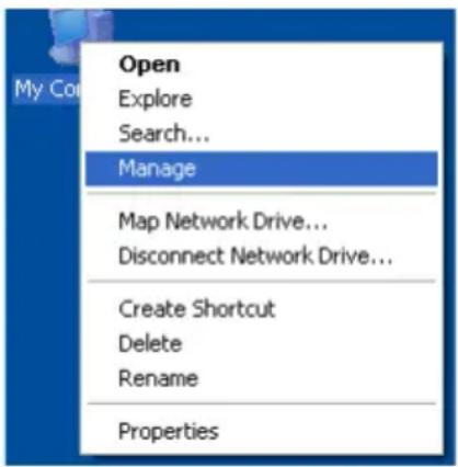
- From the desktop, right-click the My Computer icon and choose Manage from the popup menu. The Computer Management window opens.
- From the left menu, click Disk Management. The Disk Management window opens with your new logical disk identified as Disk 1. The Initialize Wizard appears automatically.
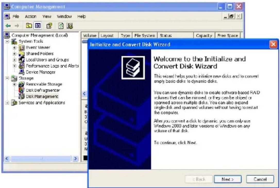
- Click the Next button to start the Wizard.
- In the following windows, choose Disk 1 to Initialize. Do not choose any disks to Convert. Click the Finish button to Initialize the logical disk.
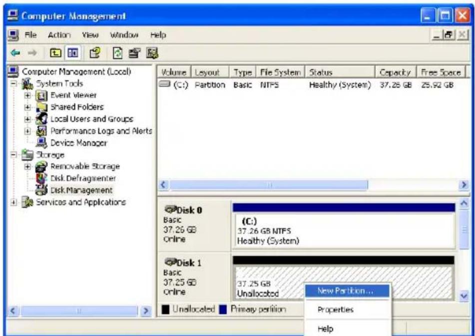
- Right-click the Unallocated portion of Disk 1 and choose New Partition... from the popup menu. The New Partition Wizard appears.
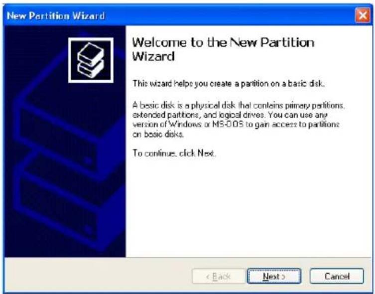
- Click the Next button to start the wizard.
-
In the following windows, do the following actions. Click Next to move to the next window.
-
Choose Primary Partition
- Specify the maximum available partition size in MB
- Assign the available drive letter of your choice
- Choose Format this partition with the following settings
- File system: NTFS
- Allocation unit size: Default
• Volume label: Enter your choice of name -
Do not check "Perform a quick format" or "Enable file and folder compression"
-
Review your selections and click Finish. The New Partition Wizard will disappear while partitioning and formatting begin.
This process will take some time. The Disk Management window displays the progress.
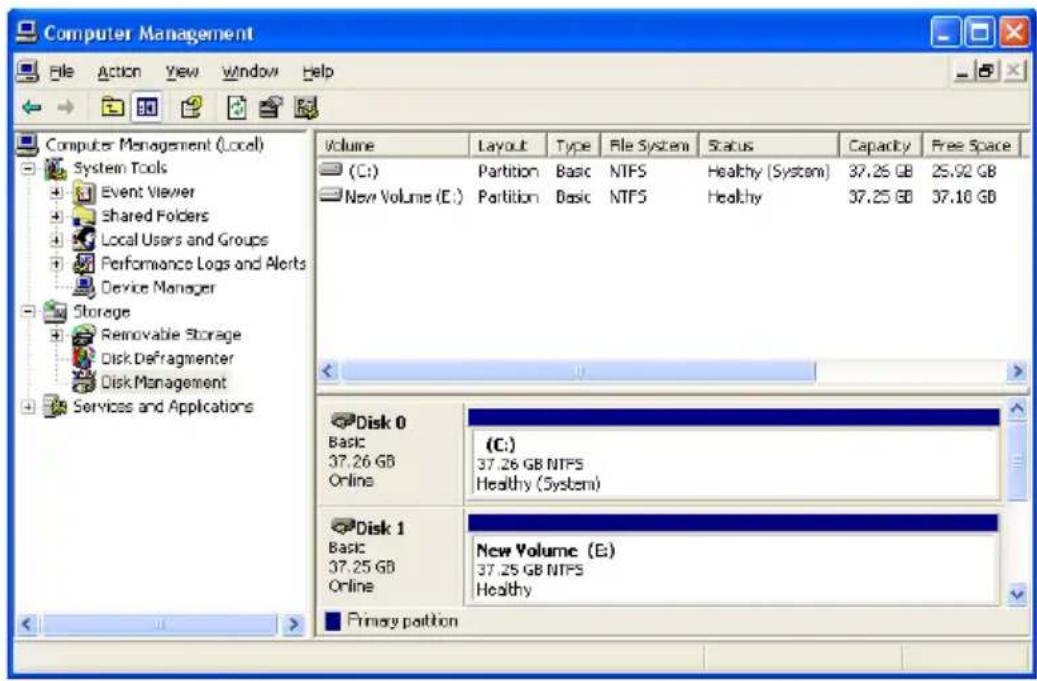
When formatting is complete, your logical disk will appear as a hard drive in the Disk Management window (above) and the My Computer window (below).
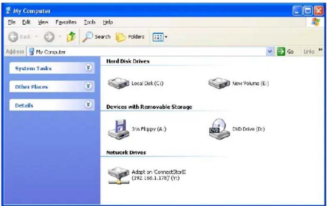
Appendix B: Upgrades
- Updating SuperTrak BIOS and Firmware (page 289)
- Updating WebPAM PRO (page 290)
Updating SuperTrak BIOS and Firmware
Follow this procedure to upgrade the BIOS and Firmware on your SuperTrak EX4650, EX8650, EX8654, EX8658, or EX16650 Controller card.
The SuperTrak card must be properly installed in your PC or server in order to perform the update. See “Installing the SuperTrak Card” on page 9 for more information.
Downloading BIOS and Firmware File
- Go to the Promise Support Website at http://support.promise.com/.
- Click Downloads.
- Click the Select Product popup menu and choose SuperTrak EX4350/EX8650/EX8654/EX8658/EX16650.
- Click the Select Category popup menu and choose All.
- Click the GO button.
The list of available downloads displays. The firmware and BIOS come together in a single package.
- Click the package you want. Be sure you choose the latest version.
- In the File Download dialog box, click the Save button.
- In the Save As dialog box, direct the file to save to a convenient location on your PC.
- Continue the update procedure in WebPAM PRO. See “Updating the Firmware” on page 132.

Important
- After you update your BIOS and Firmware, install the latest SuperTrak driver for your OS. See “Chapter 3: Installing Drivers” on page 63.
- If you also plan to update the firmware on a VTrak RAID subsystem or JBOD enclosure, download the firmware packages for those products separately.
Updating WebPAM PRO
Follow this procedure to upgrade the WebPAM PRO Software on your PC or server.
Downloading the WebPAM PRO Update File
- Go to the Promise website http://support.promise.com/.
- Click Downloads.
- Click the Select Product popup menu and choose SuperTrak EX4350/EX8650/EX8654/EX8658/EX16650.
- Click the Select Category popup menu and choose Utility.
- Click the GO button.
The list of the current WebPAM PRO software displays. Promise provides versions of WebPAM PRO software for Windows and Linux. Be sure you choose the latest version. - Click the WebPAM PRO file you want.
- In the File Download dialog box, click the Save button.
- In the Save As dialog box, direct the software to save to a convenient location on your PC.
- Unzip the downloaded WebPAM package.
The result is a single installer file.
Installing the WebPAM PRO Update File
You must manually uninstall the existing version of WebPAM PRO before installing the new one.
See “Installing WebPAM PRO onto Windows” on page 40 or “Installing WebPAM PRO onto Linux” on page 49.
Logging into WebPAM PRO
The new version of WebPAM PRO has the same login procedure as previous version. See “Logging into WebPAM PRO” on page 58 or page 109.
Appendix C: Battery Backup Unit
The Battery Backup Unit (BBU) maintains power to the cache on the SuperTrak EX Controller card, when a power failure occurs to the Host PC. The failure could be due to a problem with the PC's power supply, a cessation of electrical service, or an accidental disconnection of the power cable.
When power is interrupted, any data in the controller's cache is lost. The BBU maintains power to the cache so that any data stored there is saved until it can be written to a physical drive.
The BBU is available as a kit, sold separately from the SuperTrak EX Controller card.
• SuperTrak EX4650 and EX8650 take BBU-Plus II or BBU-Plus III
• SuperTrak EX8654, EX8658, and EX16650 take BBU-Plus III.
Be sure you obtain and install the correct kit for your controller.
The BBU kit includes the following components:
- Battery Assembly – Includes a lithium battery and holder
- Mounting screws (3)
Figure 1. The BBU-Plus III kit
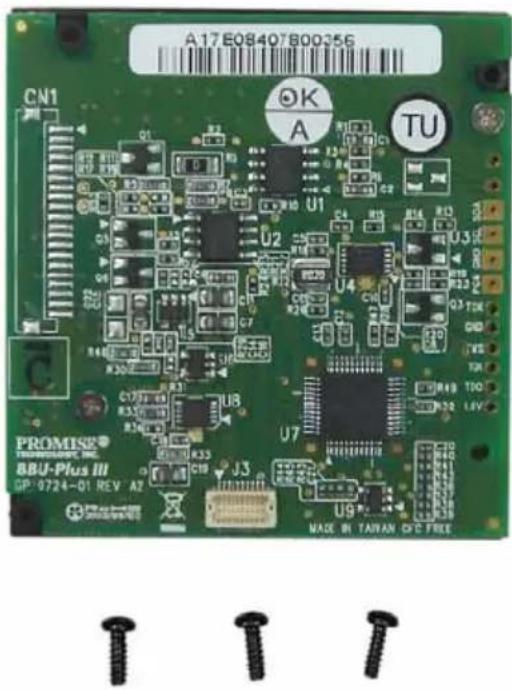
Installing the BBU

Warning
The electronic components on the SuperTrak EX Controller cards are sensitive to damage from Electro-Static Discharge (ESD). Observe appropriate precautions at all times when handling the SuperTrak card or its subassemblies.

Warning
Before installing the BBU onto SuperTrak EX Controller card, backup any important or useful data. Failure to follow this accepted PC practice could result in data loss.
To install the BBU onto your SuperTrak EX Controller card in the Host PC:
- Power down your system.
- Remove the cover of your system.
- Detach the SAS multi-lane cables from the SuperTrak EX Controller card.
- Remove the screw holding the SuperTrak EX Controller card to the system case.
- Gently pull the SuperTrak EX Controller card out of the PCI-Express slot and remove it from the system.
- Place the SuperTrak EX Controller card on an anti-static surface with the connectors facing up.
- Attach the BBU module connector on the Battery Assembly to the BBU module connector on the SuperTrak EX Controller card. See Figure 2.
Figure 2. BBU module connectors on EX4650. Other models are similar
SuperTrak EX Controller Battery Assembly
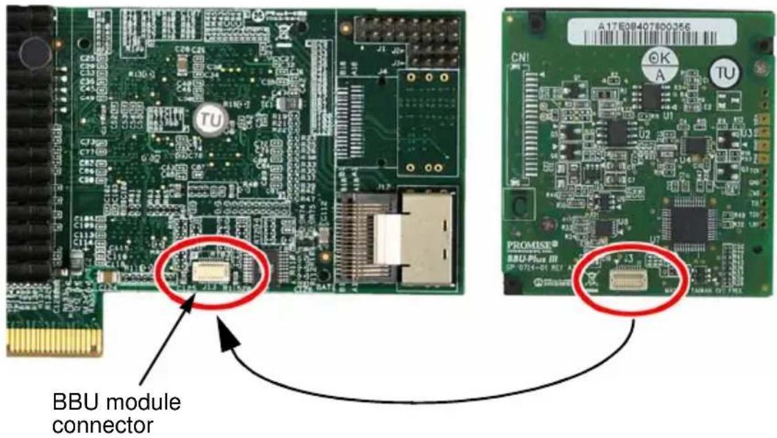
- From the opposite side of the SuperTrak EX Controller card, insert and snug the three screws to secure the Battery Assembly.
Figure 3. Three screws secure the Battery Assembly. The EX4650 is shown. Other models are similar
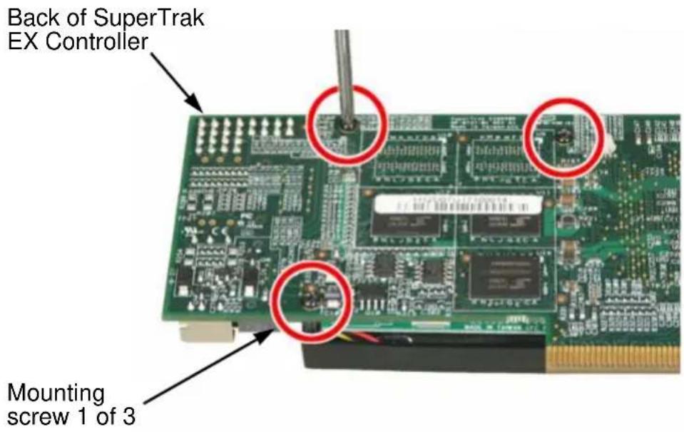
-
Install the SuperTrak EX Controller card back into its PCI-Express slot.
-
Replace the screw holding the SuperTrak EX Controller card to the system case.
- Attach the SAS multi-lane cables to the SuperTrak EX Controller card.
- Replace the cover of your system.
- Power-up the system and launch WebPAM PRO.
See "Logging into WebPAM PRO" on page 109.
After installation and power-up, a new battery takes several hours to charge. From that time, it should show Fully Charged. See “Viewing Battery Information” on page 145.
The BBU module is covered by a one-year warranty. See “Limited Warranty” on page 280.
Appendix D: LED Backplane Connections
- Schematic Diagrams (below)
- Direct LED Display (page 297)
- Aggregate LED Display (page 297)
• Global LED Display (page 298)
Schematic Diagrams
To set up LED configuration for your enclosure or PC, make your backplane connections as shown below. You can make connections for:
- Aggregate LEDs
- Global LEDs in two colors
- Direct connection – Individual fault and activity LEDs
For SuperTrak EX8654 and EX8658, note that only the interior SAS Ports have individual LED pins.
For more information, see "Installing the SuperTrak Card" on page 9 and the user manual for your PC or enclosure.
Figure 1. SuperTrak Aggregate and Global LED backplane connections
Backplane SuperTrak Controller Card
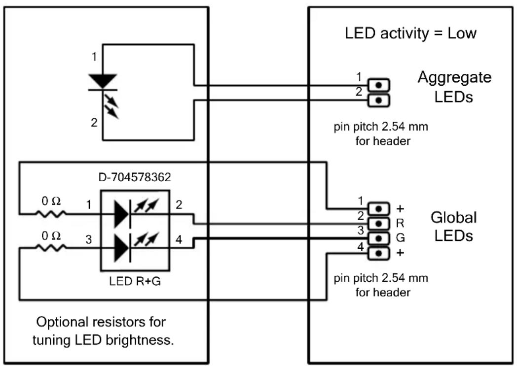
Figure 2. SuperTrak fault and activity LED connections
![graph TD A["3.3 V 3.3 V"] --> B["330 Ω 1"] A --> C["330 Ω 1"] A --> D["330 Ω 1"] A --> E["330 Ω 1"] A --> F["330 Ω 1"] A --> G["330 Ω 1"] A --> H["330 Ω 1"] A --> I["330 Ω 1"] A --> J["330 Ω 1"] A --> K["330 Ω 1"] A --> L["330 Ω 1"] A --> M["330 Ω 1"] A --> N["330 Ω 1"] A --> O["330 Ω 1"] A --> P["3…](/content/2026/05/785299/images/5258a3024d968db0c0e71e142aa7c005940b96878119612ca9ac886c37cfbfa8.jpg)
For LED status and behavior information, see the tables on the following pages.
Direct LED Display
Direct LEDs, glow and blink in response to the SuperTrak's firmware status.
| Fault LED | Activity LED | Firmware Status |
| OFF OFF | No physical drive | |
| ON ON | Unconfigured physical drive | |
| OFF ON | Configured physical drive – Status OK | |
| ON ON | Configured physical drive – Status Not OK | |
| OFF ON | Global spare drive – Status OK | |
| ON ON | Physical drive – Status Dead | |
| ON ON | Stale condition | |
| Blink ON | Rebuilding | |
| OFF Blink Activity | ||
| Blink ON | Locate physical drive | |
| Blink ON | Locate logical drive | |
| Blink ON | Locate disk array |
For more information, see:
- “Managing Physical Drives” on page 90 or page 149
- "Managing Disk Arrays" on page 92 or page 156
- "Managing Logical Drives" on page 95 or page 172
- “Managing Spare Drives” on page 99 or page 178
Aggregate LED Display
Aggregate LEDs glow or blink in response to Storage Device (physical drive) activity.
| LED Storage Device Status | |
| OFF No activity | |
| ON Storage device (physical drive) activity |
Global LED Display
Global LEDs glow in response to Logical Drive status.
| LED Logical Drive Status | |
| Dark System off | |
| Green Normal | |
| Amber Logical Drive Critical | |
| Red Logical Drive Offline |
When a Global LED glows amber or red, you must diagnose and resolve the logical drive problem in the SuperBuild BIOS or in WebPAM PRO.
See "Chapter 8: Troubleshooting" on page 261.
Index
Numerics
10GBTruncate 247
2 TB limitation 245
A
About This Manual 1
Adaptive Writeback Cache 145, 246
add
host 122
subsystem 122
Agent, WebPAM PRO 38, 123, 129
airflow, PC or server 8, 272
alias
controller 144
disk array 93, 94, 161
logical drive 96, 98, 161, 165
physical drive 152
subsystem 132
Auto Rebuild enable 137
axles
RAID 50 235
RAID 60 238
specify number 97, 161
B
background activity
run 138
settings 137
view 136
backplane, LED connections 295
battery
backup unit (BBU) 291
information 145
not charging 272
BIOS
downloading 289
SuperTrak 18, 85
blank browser screen 272
block size, see stripe size 244
browser screen, blank 272
browser support for WebPAM PRO 4, 39
buzzer 106, 261
information 147
settings 146
silencing 146
testing 146
C
capacity
disk array 92
logical drive 96, 162, 165
physical drive 90
spare drive 179
capacity coercion
defined 246
settings 144
check table 176
CIM
client settings 129
server settings 129
clear
event logs 104
NVRAM event log 136
orphan watermark 145
runtime event log 135
statistical data 132
CLI
commands, listed 190
CLI, cont.
install
FreeBSD 36
Linux 29
VMware 37
Windows 23
notes, conventions 189
open 28, 185
start 28, 185
Client/Server, WebPAM PRO 123
connection, in-band versus out-of-band 123
controller
alias 144
information 89, 142
selection 89
settings 144
statistics 144
create
disk array 19, 93, 157
logical drive 20, 96, 165
spare drive 99, 179
user 120
critical logical drive 267, 270
D
dedicated spare drive 248
degraded logical drive 172
delete
disk array 94, 163
Event Frame 116
host 123
logical drive 98, 166
scheduled activity 141
spare drive 101, 180
subsystem 123
user 120
dimensions, SuperTrak card 6
disk array
capacity 92
create 19, 93
create advanced 161
create automatically 158
create express 159
create manually 161
delete 94, 163
expansion 253
information 92, 163
list 92
locate 156
migrate 167, 248
name or alias 93, 94, 161
no mixing HDD and SSD 17, 93, 100, 158, 159, 161, 191, 220
prepare for transport 171
rebuild 168, 270
run Media Patrol 169
run PDM 169
settings 94, 164
status 93, 163
transitioning 170
view 156
downloading
BIOS 289
drivers 63
firmware 289
WebPAM PRO 290
drivers
downloading 63
FreeBSD 80
installation media 64
Miracle Linux 79
openSUSE Linux 77
RedHat Linux 74
SuSE SLES Linux 78
Windows Server 2003 70
drivers, cont.
Windows Server 2008 66
Windows Vista 68
Windows XP 72
E
messages 265
service settings 127
status 126
test 128
enable
Auto Rebuild 137
Media Patrol 137
SMART 144
enclosure
IDs 15
information 148
JBOD 14, 16
polling interval 145
SGPIO 15
SuperSwap 16
third party 149, 156, 173, 182
virtual 15, 149, 156, 173, 182
VTrak 14, 150, 157, 173, 182
error block threshold setting 137
Event Frame
deleting 116
refresh time 128
saving 116
viewing 115
event logs
clear 104
SuperBuild 103
expansion 167, 248
ranges of 253
Extended SMTP 128
F
FAQs
installation 275
physical drives 274
post installation 276
pre-installation 273
find failed drive
SuperBuild 267
WebPAM PRO 268
firmware
downloading 289
update 124, 132
first-time setup, WebPAM PRO 60
Forced Read Ahead Cache 145, 246
format logical drive 248, 285
FreeBSD
installing
CLI 36
driver 80
G
GBTruncate 246
global spare drive 248
GRPRounding 247
H
Header 113
health, subsystem 133
host
add 122
delete 123
information 130
hot spare drive 248
|
ID numbers and SAS connections 15
in-band versus out-of-band 123
Inconsistent Block Table 177
information
battery 145
buzzer 147
controller 142
disk array 92, 163
enclosure 148
host 130
logical drive 95, 183
logical drives 172, 173
physical drive 90, 151
spare drive 99
subsystem 131
subsystem/host 122
user 118
initialization
settings 137
initialization, logical drive 97, 162, 166, 175, 247
installing
BBU kit 292
CLI
FreeBSD 36
Linux 29
VMware 37
Windows 23
FreeBSD driver 80
Miracle Linux driver 79
openSUSE Linux driver 77
RedHat Linux driver 74
SuperTrak EX Controller card 9
SuSE SLES Linux driver 78
VMware driver 82
WebPAM PRO
Linux 49
Windows 40
Windows Server 2003 driver 70
Windows Server 2008 driver 66
installing, cont.
Windows Vista driver 68
Windows XP driver 72
J
Java Runtime Environment 39
JBOD enclosure 14, 16, 150, 157, 173, 182
L
language, WebPAM PRO 115
LED behavior and SuperTrak status 262, 297
LED pins
backplane 295
SuperTrak 12
Linux
installing
drivers 74–79
WebPAM PRO 49
list
disk arrays 92
logical drives 95
physical drives 90, 149
scheduled activities 139
spare drives 99, 178
locate
disk array 156
logical drive 173, 182
physical drive 149
logging into WebPAM PRO 58, 109
logging out of WebPAM PRO 117
logical drive
2 TB limitation 245
axles 97, 161
capacity 21, 96, 162, 165
check table 176
create 20, 96, 165
critical 267, 270
degraded 172
delete 98, 166
information 95, 172, 173, 183
initialization 97, 162, 166, 175, 247
list 95
list of all 182
locate 173, 182
name or alias 21, 96, 98, 161, 165, 174
offline 267
partition and format 248, 285
RAID level 21, 96, 161, 165
read cache policy 22, 97, 98, 162, 165, 175
Redundancy Check 176
sector size 21, 96, 162, 165
settings 98, 174
statistics 174
status 95, 96, 172
stripe size 21, 96, 162, 165
synchronizing 166, 174
write cache policy 22, 97, 98, 162, 166, 175
login screen, WebPAM PRO 59, 111
M
maintenance user 120
Management View 114
Media Patrol
and PDM 255
defined 255
enable 137
run 138
run on disk array 169
scheduling 139
settings 137
migrate
disk array 167, 248
settings 137
multi-lane SAS cable 12, 292, 294
N
NVRAM event log
clear 136
save 136
view 135
0
offline logical drive 267
online expansion 167, 248
orphan watermark, clear 145
OS support for WebPAM PRO 3, 38
out-of-band versus in-band 123
overview of SuperTrak 2
P
partition logical drive 248, 285
password
change 119
WebPAM PRO 59, 111
PCI-Express slot 9, 292
PDM
and Media Patrol 255
defined 255
running on a physical drive 138
running on disk array 169
settings 137
triggers 137, 255
PFA condition 152, 269
Phys
enclosures 15
EX16650 12
EX4650 10
EX8650 10
EX8654 11
EX8658 11
physical drive ID ranges 15
physical drive
alias 152
capacity 90
capacity coercion 144, 246
configuration status 151
find failed 267, 268
global settings 150
IDs 15
information 90, 151
list 90, 149
locate 149
management 90
operational status 151
PDM 138, 169
PFA condition 152, 269
problems 91, 269
stale condition 152, 269
statistics 151
status 164
polling interval 145
popup message 265
power user 120
Predictive Data Migration, see
PDM 255
problems
logical drive 267
physical drive 91, 269
Product Overview 2
R
RAID
choosing a RAID level 240
introduction to 227
VTrak subsystem 148
RAID level
logical drive 96, 161, 165
migrate 167, 248
RAID 0
applications 240
description 228
RAID level, cont.
RAID 1
applications 240
description 229
RAID 10
applications 242
description 233
RAID 1E
applications 241
description 230
RAID 5
applications 241
description 231
RAID 50
applications 243
description 234
RAID 6
applications 242
description 232
RAID 60
applications 243
description 237
recommendations 240
read cache policy
defined 246
logical drive 97, 98, 162, 165
Read Check Table 177
reassigned block threshold setting
137
rebuild
disk array 168, 270
settings 137
red X 265
RedHat, WebPAM PRO icon in ap-
plication menu 57
Redundancy Check
run on logical drive 176
scheduling 139
settings 137
refresh interval, Event Frame 128
refresh screen, WebPAM PRO 130
returning product for repair 282
revertible spare drive 170, 178, 179, 248
run
background activity 138
Media Patrol 138
Redundancy Check 176
runtime event log
clear 135
save 134
view 134
S
SAS
breakout cable 15
connections and ID numbers 15
data cable 16
diamond port 14
expanders 15, 16, 17
fanout cable 14
multi-lane cable 9, 12, 14, 292, 294
phys and port IDs 15
save
Event Frame 116
NVRAM event log 136
runtime event log 134
scheduled activities
delete 141
list 139
scheduling
Media Patrol 139
Redundancy Check 139
Spare Check 139
sector size
defined 244
logical drive 96, 162, 165
settings
background activities 137
buzzer 146
capacity coercion 144
CIM client 129
CIM server 129
controller 144
disk array 94, 164
email service 127
error block threshold 137
logical drive 98, 174
other users 118
physical drives 150, 152
reassigned block threshold 137
SMART logging 155
spare drives 100, 180
user 119
privileges 124
user privileges 120, 130
web server 126
SGPIO enclosure 15
silencing the buzzer 146
SMART Log
basic information 153, 154
settings 155
SMART, enable 144
Software Management 126
Spare Check
running 181
scheduling 139
spare drive
capacity 179
create 99, 179
dedicated to array 100, 179
dedicated to disk arrays 178
defined 248
delete 101, 180
information 99
spare drive, cont.
list 99, 178
physical drive ID 99
revertible 100, 178, 179
settings 100, 180
spare check 181
status 99, 178
specifications 6
stale condition 152, 269
statistics
clear 132
controller 144
logical drive 174
physical drive 151
status
disk array 92, 93, 163
email 126
logical drive 93, 95, 96
logical drives 172
physical drive 90, 151, 164
spare drives 99, 178
subsystem 133
web server 126
Storage Network 116
stripe size 21
defined 244
logical drive 96, 162, 165
subsystem
add 122
alias 132
delete 123
health 133
information 131
JBOD 14, 16
subsystem/host information 122
super user 120
SuperBuild
accessing 85
background activity 102
buzzer 106, 261
SuperBuild, cont.
controller information 89
controller selection 89
enter 18
event logs 103
logical drive management 95
main menu 18, 88
physical drive management 90
spare drive management 99
Time Sync 105
SuperSwap enclosure 14, 16
SuperTrak
Advanced Design 4
Compatibility 5
installing 9
LED behavior 262, 297
LED pins 12
overview 2
specifications 6
unpacking 7
XOR microprocessor 2
SuperTrak BIOS 18, 85
critical screen 86
normal screen 86
offline screen 87, 264
Synchronization
settings 137
synchronizing a logical drive 166,
174
system configuration, view 141
T
TableRounding 247
technical support, contacting 277
temperatures, operating 6, 8, 272
test email 128
testing the buzzer 146
Time Sync 105
Tomcat server 127
Transition
automatic 258
defined 256
disk array 170
manual 258
settings 137
transport, prepare disk array 171
Tree View 113
U
update firmware 124, 132
user
create 120
delete 120
information 118
interface, WebPAM PRO 112
name in WebPAM PRO 59, 111
password, change 119
privileges 120, 124, 130
privileges defined 120
settings 119
settings of other users 118
Utility Server 38, 129
V
view
background activities 136
disk array 156
NVRAM event log 135
runtime event log 134
scheduled activities 139
system configuration 141
view-only user 120
virtual enclosure 15
VMware
installing
CLI 37
drivers 82
VTrak JBOD 14, 16, 150, 157, 173, 182
VTrak JBOD enclosure 133
VTrak RAID subsystem 148
W
warranty 280
web server
settings 126
status 126
WebPAM PRO
Agent 38, 123, 129
alias for subsystem 132
background activity
run 138
schedule 139
settings 137
battery information 145
blank screen 272
browser support 4, 39
buzzer 146
CIM client settings 129
CIM server settings 129
Client/Server 123
components 38
controller
info 142
settings 144
statistics 144
description 3
disk array
auto create 158
delete 163
express create 159
info 163
locate 156
manual create 161
Media Patrol 169
migrate 167
WebPAM PRO, cont.
disk array, cont.
PDM 169
prepare for transport 171
rebuild 168, 270
settings 164
transition 170
display language 115
downloading 290
email service 127
enclosures 148
Event Frame 115
event frame refresh 128
extended SMTP 128
External SSL Security option 45, 54
find failed drive 268
firmware update 124, 132
first-time setup 60
Header 113
host
add 122
delete 123
info 122
icon in RedHat application
menu 57
installing
Linux 49
Windows 40
Java Runtime Environment 39
logging in 58, 109
logging out 117
logical drive
check table 176
create 165
delete 166
info 172, 173, 183
initialize 175
locate 173, 182
WebPAM PRO, cont.
logical drive, cont.
Redundancy Check 176
settings 174
statistics 174
login screen 59, 111
Management View 114
Media Patrol 138
NVRAM event log 135
orphan watermark 145
OS support 3, 38
password 59, 111
password, change 119
PDM 138
physical drive
global settings 150
info 151
locate 149
PFA condition 152, 269
settings 152
stale condition 152, 269
statistics 151
refresh screen 130
Regular connection 58, 110
runtime event log 134
Secure connection 58, 110
session time out setting 127
spare drive
create 179
delete 180
settings 180
spare check 181
statistical data, clear 132
Storage Network 116
subsystem
add 122
delete 123
health 133
info 122
Tomcat Server 127
Tree View 113
WebPAM PRO, cont.
user
create 120
delete 120
interface 112
name 59, 111
password 119
privileges 124, 130
settings 118
Utility Server 38, 129
Web Server 126
Windows
installing
drivers 66–72
WebPAM PRO 40
write cache policy
defined 246
logical drive 97, 98, 162, 166
Write Check Table 177
Y
yellow!265
- COPYRIGHT
- TRADEMARKS
- IMPORTANT DATA PROTECTION INFORMATION
- NOTICE
- RECOMMENDATIONS
- RADIO FREQUENCY INTERFERENCE STATEMENT
- CAUTION
- CONTENTS
- CHAPTER 1: INTRODUCTION .....1
- CHAPTER 2: INSTALLATION .....7
- CHAPTER 3: INSTALLING DRIVERS ....63
- CHAPTER 3: INSTALLING DRIVERS, CONT
- CHAPTER 4: SUPERBUILD™ UTILITY .....85
- CHAPTER 4: SUPERBUILD™ UTILITY, CONT
- CHAPTER 5: MANAGEMENT WITH WEBPAM PRO .....109
- CHAPTER 5: MANAGEMENT WITH WEBPAM PRO, CONT
- CHAPTER 6: MANAGEMENT WITH THE CLI .....185
- CHAPTER 7: TECHNOLOGY BACKGROUND .....227
- CHAPTER 7: TECHNOLOGY BACKGROUND, CONT
- CHAPTER 8: TROUBLESHOOTING .....261
- CHAPTER 9: SUPPORT .....273
- APPENDIX A: PARTITION AND FORMAT .....285
- APPENDIX B: UPGRADES .....289
- APPENDIX C: BATTERY BACKUP UNIT .....291
- APPENDIX D: LED BACKPLANE CONNECTIONS .....295
- INDEX. 299
- CHAPTER 1: INTRODUCTION
- ABOUT THIS MANUAL
- NOTE
- IMPORTANT
- WARNING
- PRODUCT OVERVIEW
- XOR MICROPROCESSOR
- HOT-SWAPPING
- WEBPAM PRO MANAGEMENT SOFTWARE
- OPERATING SYSTEM SUPPORT
- BROWSER SUPPORT
- KEY FEATURES AND BENEFITS
- SPECIFICATIONS
- CHAPTER 2: INSTALLATION
- UNPACKING THE SUPERTRAK CARD
- INSTALLING THE SUPERTRAK CARD
- CONNECTING SUPERTRAK TO A SUPERSWAP ENCLOSURE
- CONNECTING SUPERTRAK TO A VTRAK JBOD ENCLOSURE
- SAS CONNECTIONS AND ID NUMBERS
- SCENARIO 1: VIRTUAL ENCLOSURE – SGPIO
- SCENARIO 2: VIRTUAL ENCLOSURE – HOST PC
- SCENARIO 3: EXTERNAL ENCLOSURES – DAISY CHAIN
- SCENARIO 4: EXTERNAL ENCLOSURES – PARALLEL
- SCENARIO 5: SAS EXPANDERS
- CHOOSING THE PHYSICAL DRIVES
- CREATING A LOGICAL DRIVE
- INSTALLING THE CLI
- INSTALLING ONTO WINDOWS
- INSTALLING ONTO LINUX
- INSTALLING THE CLI ONTO FREEBSD
- INSTALLING THE CLI ONTO VMWARE
- INSTALLING WEBPAM PRO
- UTILITY SERVER
- AGENT
- JRE
- INTERNET BROWSER
- INSTALLING WEBPAM PRO ONTO WINDOWS
- INSTALLING WEBPAM PRO ONTO LINUX
- LOGGING INTO WEBPAM PRO
- LOGGING IN AT THE HOST PC
- LOGGING IN OVER THE NETWORK
- REGULAR CONNECTION
- SECURE CONNECTION
- NOTES
- LOGIN SCREEN
- SETTING UP WEBPAM PRO
- CHAPTER 3: INSTALLING DRIVERS
- DRIVER INSTALLATION MEDIA
- WINDOWS
- LINUX AND FREEBSD
- WINDOWS SERVER 2008
- NEW OS INSTALLATION
- EXISTING SYSTEM
- CONFIRMING DRIVER INSTALLATION
- WINDOWS VISTA
- WINDOWS SERVER 2003
- WINDOWS XP
- RED HAT LINUX ENTERPRISE 4.4, 4.5, 4.6, 4.7
- FEDORA CORE 6
- FEDORA CORE 7, 8
- OPENSUSE 10.2, 10.3, 10.5, 11
- SLES 10, 10 SP1, 10 SP2
- MIRACLE LINUX 4
- FREEBSD 6.1, 6.2, 6.3, 7.0
- OPTION 1. DEVICE NODE EXISTS
- OPTION 2. DEVICE NODE DOES NOT EXIST
- VMWARE ESX SERVER 3.0.2, 3.5.0
- REMOVE THE CD FROM THE CD-ROM
- CHAPTER 4: SUPERBUILD™ UTILITY
- SUPERTRAK BIOS
- ACCESSING THE MAIN MENU
- SELECTING A CONTROLLER
- VIEWING CONTROLLER INFORMATION
- MANAGING PHYSICAL DRIVES
- VIEWING PHYSICAL DRIVES
- VIEWING PHYSICAL DRIVE INFORMATION
- MANAGING PHYSICAL DRIVE PROBLEMS
- MANAGING DISK ARRAYS
- VIEWING DISK ARRAYS
- VIEWING DISK ARRAY INFORMATION
- CREATING A DISK ARRAY
- CHANGING DISK ARRAY SETTINGS
- REBUILDING A DISK ARRAY
- DELETING A DISK ARRAY
- MANAGING LOGICAL DRIVES
- VIEWING LOGICAL DRIVES
- VIEWING LOGICAL DRIVE INFORMATION
- INITIALIZING A LOGICAL DRIVE
- CHANGING LOGICAL DRIVE SETTINGS
- DELETING A LOGICAL DRIVE
- MANAGING SPARE DRIVES
- VIEWING SPARE DRIVES
- VIEWING SPARE DRIVE INFORMATION
- CREATING A SPARE DRIVE
- CHANGING SPARE DRIVE SETTINGS
- DELETING A SPARE DRIVE
- VIEWING BACKGROUND ACTIVITY
- MANAGING THE EVENT LOG
- VIEWING RAM EVENTS
- VIEWING NVRAM EVENTS
- CLEARING THE EVENT LOGS
- WORKING WITH TIME SYNC
- SETTING THE TIME ZONE
- SYNCHRONIZING TIME WITH AN EMBEDDED SITE
- USING THE MISCELLANEOUS MENU
- MAKING THE SAS READY LED SETTING
- MAKING THE SGPIO BACKPLANE SETTING
- WORKING WITH THE BUZZER
- ENABLING OR DISABLING THE BUZZER
- CHAPTER 5: MANAGEMENT WITH WEBPAM PRO
- ACCESSING THE INTERFACE
- USING THE HEADER
- USING TREE VIEW
- USING MANAGEMENT VIEW
- CHOOSING A DISPLAY LANGUAGE
- VIEWING THE EVENT FRAME
- SAVING THE EVENT FRAME
- DELETING THE EVENT FRAME
- VIEWING THE STORAGE NETWORK
- LOGGING OUT OF WEBPAM PRO
- MANAGING USERS
- VIEWING USER INFORMATION
- MAKING USER SETTINGS
- MAKING YOUR OWN USER SETTINGS
- CHANGING A USER'S PASSWORD
- CHANGING YOUR OWN PASSWORD
- CREATING A USER
- TO CREATE A USER
- LIST OF USER PRIVILEGES
- DELETING A USER
- WORKING WITH SUBSYSTEM/HOST MANAGEMENT
- VIEWING SUBSYSTEM/HOST INFORMATION
- ADDING A SUBSYSTEM OR HOST
- IN-BAND VERSUS OUT-OF-BAND
- IN-BAND CONNECTION
- OUT-OF-BAND CONNECTION
- DELETING A SUBSYSTEM OR HOST
- SETTING USER PRIVILEGE
- UPDATING THE FIRMWARE ON MULTIPLE SYSTEMS
- CAUTIONS
- MANAGING SOFTWARE SERVICES
- VIEWING SERVICE STATUS
- CHANGING WEB SERVER SETTINGS
- RESTARTING THE TOMCAT SERVER
- LINUX
- SETTING UP EMAIL SERVICE
- SETTING UP EXTENDED SMTP
- SENDING A TEST EMAIL MESSAGE
- SETTING EVENT FRAME REFRESH TIME
- CHANGING CIM CLIENT SETTINGS
- CHANGING CIM SERVER SETTINGS
- MANAGING THE HOST
- VIEWING HOST INFORMATION
- SETTING USER RIGHTS
- REFRESHING THE WEBPAM PRO SCREEN
- MANAGING THE SUBSYSTEM
- VIEWING SUBSYSTEM INFORMATION
- CLEARING STATISTICAL DATA
- SETTING AN ALIAS FOR THE SUBSYSTEM
- UPDATING THE FIRMWARE
- SUPERTRAK CONTROLLER CARD
- VTRAK JBOD ENCLOSURE
- CHECKING SUBSYSTEM HEALTH
- VIEWING THE RUNTIME EVENT LOG
- SEVERITY DEFINITIONS
- SAVING THE RUNTIME EVENT LOG
- CLEARING THE RUNTIME EVENT LOG
- VIEWING THE NVRAM EVENT LOG
- SAVING THE NVRAM EVENT LOG
- CLEARING THE NVRAM EVENT LOG
- VIEWING CURRENT BACKGROUND ACTIVITIES
- MAKING BACKGROUND ACTIVITY SETTINGS
- RUNNING BACKGROUND ACTIVITIES
- RUNNING MEDIA PATROL
- RUNNING PDM
- TO RUN PDM
- VIEWING SCHEDULED ACTIVITIES
- SCHEDULING AN ACTIVITY
- DELETING A SCHEDULED ACTIVITY
- VIEWING SYSTEM CONFIGURATION
- MANAGING THE CONTROLLER
- VIEWING CONTROLLERS INFORMATION
- VIEWING CONTROLLER STATISTICS
- MAKING CONTROLLER SETTINGS
- CLEARING AN ORPHAN WATERMARK
- VIEWING BATTERY INFORMATION
- SILENCING THE BUZZER
- MAKING BUZZER SETTINGS
- TESTING THE BUZZER
- VIEWING BUZZER INFORMATION
- MANAGING ENCLOSURES
- VIEWING ENCLOSURE INFORMATION
- VIEWING A LIST OF PHYSICAL DRIVES
- LOCATING A PHYSICAL DRIVE
- VIRTUAL OR THIRD PARTY ENCLOSURES
- PROMISE ENCLOSURES
- MAKING GLOBAL PHYSICAL DRIVE SETTINGS
- ADJUSTABLE ITEMS
- VIEWING PHYSICAL DRIVE STATISTICS
- MAKING PHYSICAL DRIVE SETTINGS
- CLEARING STALE AND PFA CONDITIONS
- VIEWING THE SMART LOG
- VIEWING ADVANCED SMART LOG INFORMATION
- SAVING ADVANCED SMART LOG INFORMATION
- MAKING SMART LOG SETTINGS
- LOCATING A DISK ARRAY
- CREATING A DISK ARRAY – AUTOMATIC CONFIGURATION
- CREATING A DISK ARRAY – EXPRESS CONFIGURATION
- CREATING A DISK ARRAY – ADVANCED CONFIGURATION
- STEP 1 – DISK ARRAY CREATION
- STEP 2 – LOGICAL DRIVE CREATION
- STEP 3 – SUMMARY
- DISK ARRAY OPERATIONAL STATUS
- PHYSICAL DRIVE STATUS
- MAKING DISK ARRAY SETTINGS
- TO DELETE A LOGICAL DRIVE
- CLICK THE OK BUTTON
- MIGRATING A DISK ARRAY
- REBUILDING AUTOMATICALLY
- REBUILDING MANUALLY
- RUNNING MEDIA PATROL ON A DISK ARRAY
- RUNNING PDM ON A DISK ARRAY
- TRANSITIONING A DISK ARRAY
- PREPARING A DISK ARRAY FOR TRANSPORT
- VIEWING INFORMATION FOR ALL LOGICAL DRIVES
- LOGICAL DRIVE STATUS
- LOCATING A LOGICAL DRIVE
- LOGICAL DRIVE SYNCHRONIZATION
- VIEWING LOGICAL DRIVE STATISTICS
- RUNNING REDUNDANCY CHECK
- VIEWING THE LOGICAL DRIVE CHECK TABLE
- VIEWING A LIST OF SPARE DRIVES
- TO CREATE A SPARE DRIVE
- DELETING SPARE DRIVE
- TO DELETE A SPARE DRIVE
- MAKING SPARE DRIVE SETTINGS
- TO CHANGE SPARE DRIVE SETTINGS
- RUNNING SPARE CHECK
- WORKING WITH THE LOGICAL DRIVE SUMMARY
- VIEWING A LIST OF ALL LOGICAL DRIVES
- VIEWING INDIVIDUAL LOGICAL DRIVE INFORMATION
- CHAPTER 6: MANAGEMENT WITH THE CLI
- OPENING THE CLI ON WINDOWS
- OPENING THE CLI ON LINUX, FREEBSD, AND VMWARE
- NOTES AND CONVENTIONS
- ABOUT
- USAGE
- SUMMARY
- ARRAY
- OPTIONS
- EXAMPLES
- BBM
- BGA
- BUZZ
- CHECKTABLE
- CONFIG
- CTRL
- DATE
- ENCLOSURE
- EVENT
- EXPORT
- FACTORYDEFAULTS
- INIT
- LOGDRV
- MIGRATE
- MP
- PDM
- PHYDRV
- PTIFLASH
- RC
- RB
- SC
- SMART
- SPARE
- SPATH
- STATS
- SUBSYS
- SYNC
- TOPOLOGY
- TRANSIT
- CHAPTER 7: TECHNOLOGY BACKGROUND
- INTRODUCTION TO RAID
- RAID 0 – STRIPE
- RAID 1 – MIRROR
- RAID 1E – ENHANCED MIRROR
- RAID 5 – BLOCK STRIPING WITH DISTRIBUTED PARITY
- RAID 6 – BLOCK AND DOUBLE PARITY STRIPE
- RAID 10 – MIRROR / STRIPE
- RAID 50 – STRIPED DISTRIBUTED PARITY
- RAID 50 AXLES
- RAID 60 – STRIPING OF DOUBLE PARITY
- RAID 60 AXLES
- CHOOSING A RAID LEVEL
- CHOOSING STRIPE BLOCK SIZE
- CHOOSING SECTOR SIZE
- 2 TB LIMITATION
- CHOOSING CACHE POLICY
- READ CACHE POLICY
- WRITE CACHE POLICY
- CAPACITY COERCION
- INITIALIZATION
- HOT SPARE DRIVE
- PARTITION AND FORMAT THE LOGICAL DRIVE
- RAID LEVEL MIGRATION
- RAID 0
- RAID 1
- RAID 1E
- RAID 5
- RAID 6
- RAID 10
- RAID 50
- RAID 60
- RANGES OF DISK ARRAY EXPANSION
- DELETE AND RECREATE
- MEDIA PATROL
- PREDICTIVE DATA MIGRATION (PDM)
- PDM TRIGGERS
- TRANSITION
- DRIVE FAILURE AND AUTOMATIC REBUILD
- AUTOMATIC TRANSITION
- MANUAL TRANSITION
- CHAPTER 8: TROUBLESHOOTING
- PROBLEMS REPORTED BY SUPERTRAK
- BUZZER
- LEDS
- GLOBAL LED DISPLAY
- DIRECT LED DISPLAY
- BIOS
- PROBLEMS REPORTED IN WEBPAM PRO
- OPENING WEBPAM PRO
- WHAT TO LOOK FOR
- CRITICAL & OFFLINE LOGICAL DRIVES
- FINDING THE FAILED DRIVE IN SUPERBUILD
- FINDING THE FAILED DRIVE IN WEBPAM PRO
- SALVAGING PHYSICAL DRIVES
- REBUILDING A DISK ARRAY AUTOMATICALLY
- REBUILDING A DISK ARRAY MANUALLY
- REBUILDING WITH WEBPAM PRO
- REBUILDING WITH SUPERBUILD
- RECOVERING FROM A BLANK SCREEN
- CACHE BATTERY DOES NOT CHARGE
- CHAPTER 9: SUPPORT
- FREQUENTLY ASKED QUESTIONS
- PRE-INSTALLATION (SPEED, DEVICE TYPES, CAPACITY, CABLING)
- WHAT IS THE MAXIMUM PHYSICAL DRIVE STORAGE CAPACITY OF SUPERTRAK EX SERIES
- CAN I USE ATAPI DEVICES ON THE SUPERTRAK EX SERIES
- WILL ACPI WORK WITH HDDS ON THE SUPERTRAK EX SERIES
- WHAT KIND OF PCI SLOTS DO THE SUPERTRAK EX SERIES CONTROLLERS USE
- HOW CAN I CHANGE THE RESOURCES THAT THE SUPERTRAK USES
- DRIVE ISSUES
- INSTALLATION ISSUES (CAPACITY, BOOTING)
- HOW CAN I CHANGE THE BOOT SEQUENCE BETWEEN A PCI SCSI CARD AND THE SUPERTRAK EX SERIES RAID LOGICAL DRIVE
- POST-INSTALLATION
- CONTACTING TECHNICAL SUPPORT
- TECHNICAL SUPPORT SERVICES
- UNITED STATES
- THE NETHERLANDS
- GERMANY
- ITALY
- TAIWAN
- CHINA
- LIMITED WARRANTY
- DISCLAIMER OF OTHER WARRANTIES
- YOUR RESPONSIBILITIES
- RETURNING THE PRODUCT FOR REPAIR
- APPENDIX B: UPGRADES
- UPDATING SUPERTRAK BIOS AND FIRMWARE
- DOWNLOADING BIOS AND FIRMWARE FILE
- UPDATING WEBPAM PRO
- DOWNLOADING THE WEBPAM PRO UPDATE FILE
- INSTALLING THE WEBPAM PRO UPDATE FILE
- APPENDIX C: BATTERY BACKUP UNIT
- INSTALLING THE BBU
- APPENDIX D: LED BACKPLANE CONNECTIONS
- SCHEMATIC DIAGRAMS
- AGGREGATE LED DISPLAY
- INDEX
- NUMERICS
- A
- B
- C
- D
- E
- F
- G
- H
- J
- L
- M
- N
- 0
- P
- R
- S
- T
- U
- V
- W
Brand : Promise Technology
Model : SuperTrack EX8658
Category : NAS