ECO1250SD - Air-conditioner EcoAir - Free user manual and instructions
Find the device manual for free ECO1250SD EcoAir in PDF.


User questions about ECO1250SD EcoAir
0 question about this device. Answer the ones you know or ask your own.
Ask a new question about this device
Download the instructions for your Air-conditioner in PDF format for free! Find your manual ECO1250SD - EcoAir and take your electronic device back in hand. On this page are published all the documents necessary for the use of your device. ECO1250SD by EcoAir.
USER MANUAL ECO1250SD EcoAir
Z Series Inverter Range Split Type
DC Inverter
ECO950SD
ECO1250SD
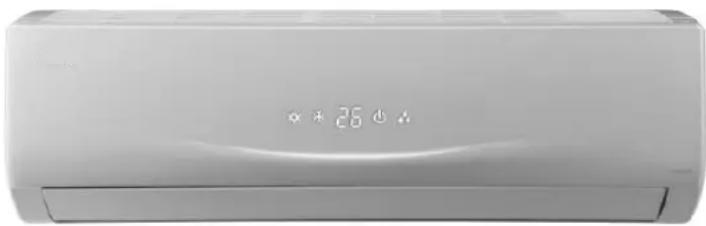
natural_image
Front view of a white air conditioner unit with digital display and control buttons (no visible text or symbols)Register your air conditioner
Model information can be found on the CE label.
Please register your product online at www.ecoair.org. For your future convenience, record the model information below.
MODEL NUMBER
SERIAL NUMBER
PURCHASE DATE
What's in the box
1 x Z Series Indoor Unit
1 x Z Series Outdoor Unit
1 x Remote Control
1 x Drain Hose
1 x User Manual
1 x Hole Cover Plate
1 x Drain Joint
4 x Wall Plugs and Screws.
1 set of Copper Pipes
This appliance can be used by minors from 8 years and above and persons with reduced physical, sensory or mental capabilities or lack of experience and knowledge if they have been given supervision or instruction concerning use of the appliance in a safe way and understand the hazards involved. Children should not play with the appliance. Cleaning and user maintenance shall not be made by minors without supervision.
WEE/EC2601UR
This marking indicates that this product should not be disposed with other household waste throughout the EU. To prevent possible harm to the environment or human health from uncontrolled waste disposal, recycle it responsibly to promote the sustainable reuse of material resources or return your used device, please use the return and collection systems . or contact the retailer where the product was purchased.They can take this product for environmental safe recycling.
R410A(R32/125: 50/50): 1975
Content
Operation and maintenance
BS Plug Wiring 1
Safety Precautions 2
Notices for use....5
Name of parts 7
Operation Remote Control 8
Emergency operation....14
Clean and care 15
troubleshooting....17
Installation service
Notices for installation 20
Installation dimension diagram 22
Installation of indoor unit 24
Installation of outdoor unit....26
Check after installation and test operation 27
BS Plug Wiring
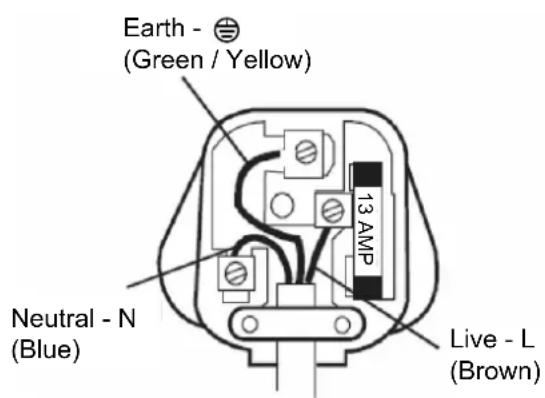
Wiring Instructions: Should it be necessary to change the plug please note the wires in the mains lead are coloured in accordance with the following code:
BLUE - NEUTRAL
BROWN - LIVE
As the colours of the wires in the mains lead of this appliance may not correspond with the coloured markings identifying the terminals in your plug, proceed as follows:
- The BLUE wire is the NEUTRAL and must be connected to the terminal which is marked with the letter N or coloured BLACK.
- The BROWN wire is the LIVE and must be connected to the terminal which is marked with the letter L or coloured RED.
- The GREEN/YELLOW is the EARTH and must be connected to the terminal which is marked with the letter E or ⊕ or coloured GREEN or GREEN/YELLOW.
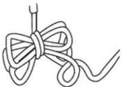
- Always ensure that the cord grip is positioned and fastened correctly.
If a 13 Amp (BS 1363) fused plug is used it must be fitted with a 13 Amp fuse. If in doubt consult a qualified electrician. (For 9000BTU and 12000BTU unit only.)
(For 18000BTU use 20 Amp (fuse) supply from the main.) (For 24000BTU use 32 Amp (fuse) supply from the main.)
Wiring for a 13 Amp Plug (BS1363)
Please note. The Earth Terminal is marked with the letter E or 🌐 Earth Symbol.
text_image
Earth - (Green / Yellow) Neutral - N (Blue) 13 AMP Live - L (Brown)
* |  |  | contact a qualified electrician |
 |  |  |  |
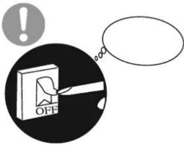 | Capacity must be sufficient.Please do not turn on or off | ||

Earth: The ground be connected! 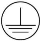 If not, please ask the qualified personnel to install. Furthermore, don't connect each wire to the gas pipe, water pipe, drainage pipe or any other improper places. If not, please ask the qualified personnel to install. Furthermore, don't connect each wire to the gas pipe, water pipe, drainage pipe or any other improper places. | Be sure to pull out the power plug when not using the air conditioner for a long time. 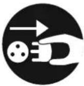 Otherwise, the accumulated dust may cause fire or electric shock. Otherwise, the accumulated dust may cause fire or electric shock. | Select the most appropriate temperature. It can preclude the electricity wasted. It can preclude the electricity wasted. |
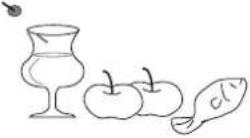
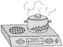
Don't leave windows and doors open for a long time while operating the air conditioner.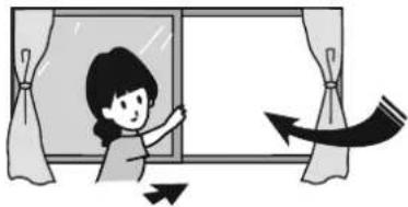 It can decrease the air conditioning capacity. It can decrease the air conditioning capacity. | Don't block the air intake or outlet vents of both the outdoor and indoor units.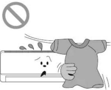 It can decrease the air conditioning capacity or cause a malfunction. It can decrease the air conditioning capacity or cause a malfunction. | Keep combustible spray away from the units more than 1m.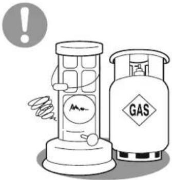 It can cause a fire or explosion. It can cause a fire or explosion. |
Please note whether the installed stand is firm enough or not. 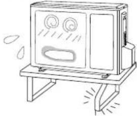 If it is damaged, it may lead to the fall of the unit and cause the injury. If it is damaged, it may lead to the fall of the unit and cause the injury. | Don't step on the top of the outdoor unit or place something on it.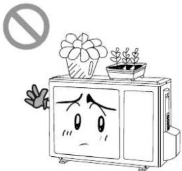 As falling off the outdoor unit can be dangerous. As falling off the outdoor unit can be dangerous. | Don't attempt to repair the air conditioner by yourself.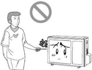 The wrong repair will lead to an electric shock or fire, so you should contact a qualified air conditioning engineer or EcoAir. The wrong repair will lead to an electric shock or fire, so you should contact a qualified air conditioning engineer or EcoAir. |

★air conditioning engineer. | ★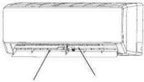 |
 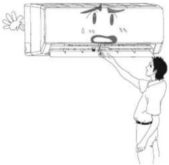 | ★★★★ 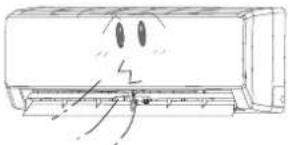  |
★ 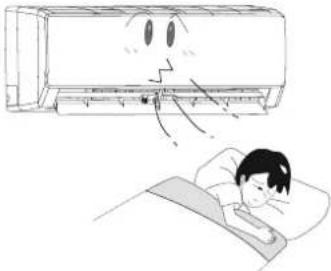 | ★ 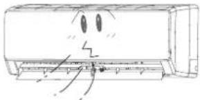  |
★  | ★   |

Notices for use
Working principle and special functions for Cooling
Principle:
Air conditioner absorbs heat in the room and discharges the heat through the outdoor that indoor ambient temperature decreased, its cooling capacity will increase or decrease by outdoor ambient temperature.
Anti-freezing function:
If the unit is running in COOL mode and in low temperature, there will be frost formed on the heat exchanger, when indoor heat exchanger temperature decreased below 0^ C indoor unit microcomputer will stop the compressor running to protect the unit.
Working principle and special functions for Heating
Principle:
* Air conditioner absorbs heat from outdoor and discharges to indoor, in this way to increase room temperature. This is the heat pump heating principle, its heating capacity will be reduced due to outdoor temperature decrease.
* If outdoor temperature becomes very low, please operate with other heating equipments.
Defrosting:
* When outdoor temperature is low but high humidity, after a while running, frost will form on outdoor unit, that will affect the heating effect, at this time, the auto defrosting function will activate, the heating will stop for 8-10 mins.
* During the auto defrosting, the fan motors of indoor unit and outdoor unit will stop.
* During the defrosting, the indoor indicator flashes, the outdoor unit may emit vapor. This is due to the defrosting, it isn't a malfunction.
* After defrosting finished, the heating will resume automatically.
The climate type of this unit is according to the nameplate.
The external static pressures at which the appliance was tested should be zero Pa.

Notices for use
Anti-cool wind function:
In "Heat" mode, under the following three kinds of state, if indoor heat exchanger doesn't arrive at certain temp, indoor fan will not act, in order to prevent cool wind blowing(within 2 mins):
- Heating starts. 2. After Auto Defrost finished. 3. Heating under the low temperature.
| ※ Working temperature range | ||
| Indoor sideDB/WB(°C) | Outdoor sideDB/WB(°C) | |
| Maximum cooling | 32/23 | 40/26 |
| Minimum cooling | 21/15 | 21/-- |
| Maximum heating | 27/--- | 24/18 |
| Minimum heating | 20/--- | -5/-6 |
The operating temperature range (outdoor temperature) for cooling and heating unit is -5°C\~40°C.

Name of Parts
Indoor unit

text_image
Air in (1) (3) (4) (5) (6) Air out The icons displayed: * : Cool ● : Dry ○ : Heat ↓ : Power BB : Set temp. (2) (7) Outdoor unit Air in (8) (9) (10) (1) Power cord (2) Remote controller (3) Front panel (4) Filter (5) Horizontal louver (6) Wall pipe (7) Binding tape (8) Connection wires (9) Drain hose (10) Drain connector
Operation of Remote Controller
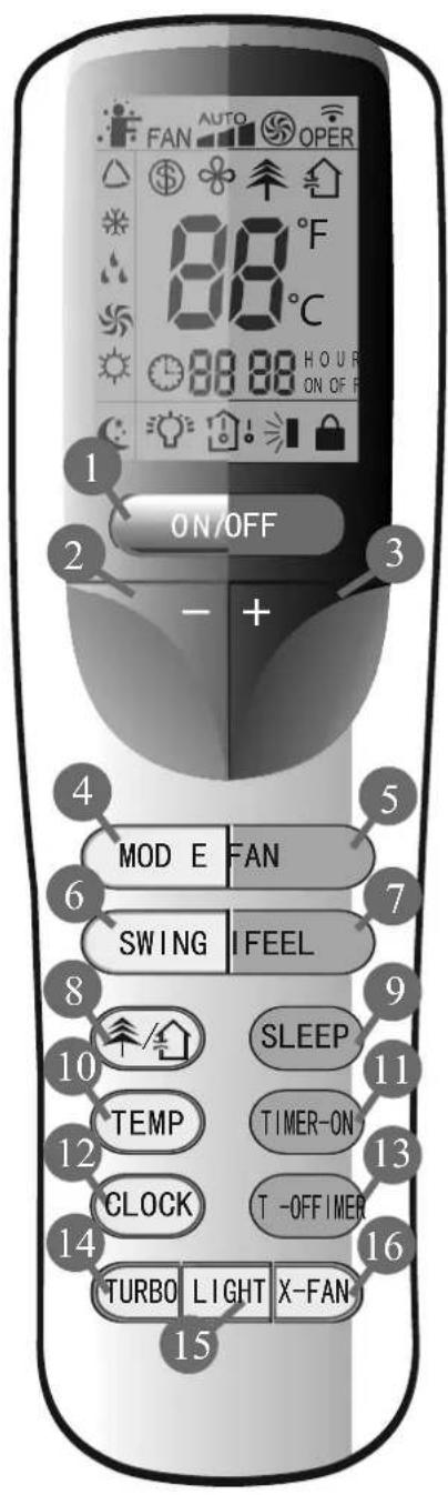
text_image
FAN AUTO OPER 88 °F 88 °C H O U R ON OF F 1 ON/OFF 2 - + 4 MOD E FAN 5 6 SWING I FEEL 7 8 9 SLEEP 10 TEMP TIMER-ON 11 12 CLOCK T-OFFIMER 13 14 TURBO LIGHT X-FAN- 151 ON/OFF
Press it to start or stop operation.
2 - : Press it to decrease temperature setting.
3 +: Press it to increase temperature setting.
4 MODE
Press it to select operation mode (AUTO/COOL/DRY/FAN/HEAT).
5 FAN Press it to set fan speed.
6 SWING Press it set swing angle.
7 I FEEL(Page 10) (optional)
8 / Press it to set HEALTH or AIR function.
9 SLEEP(page 11)
10 TEMP(page 11)
11 TIMER ON Press it to set auto-on timer.
12 CLOCK Press it set clock.
13 TIMER OFF Pressit to set auto-off timer.
14 TURBO(page 11)
15 LIGHT
Press it to turn on/off the light
16 X-FAN (page 11) (optional)

Operation of Remote Controller
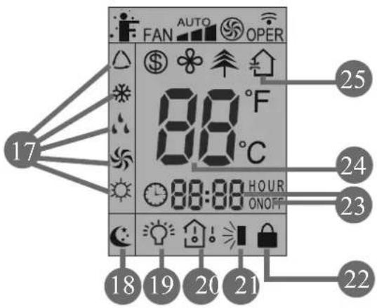
text_image
FAN AUTO OPER 88 °F C 88:00 HOUR ONOFF 17 25 24 23 18 19 20 21 2217 MODE icon:
If MODE button is pressed, current operation mode icon △(AUTO), ✉ (COOL), ⚠ (DRY), ⚣(FAN) or ⚙ (HEAT for heat pump models) will show.
18 SLEEP icon :
is displayed by pressing the S LEEP button Press this button in again to clear the display.
19 LIGHT icon:
i s displayed by pressing the LIGHT button. Press LIGHT button again to clear the display.
20 TEMP icon:
Pressing TEMP button, (set temperature), (indoor ambient temperature) (outdoor ambient temperature) is fitted.
21 Up & down swing icon:
is displayed when pressing the up & down swing down button. Press this button again to clear the display
22 LOCK icon:
is displayed by pressing "+" and "-" buttons simultaneously. press them again to clear the display.
23 SET TIME display:
After pressing TIMER button, HOUR ON or OFF will blink. This area will show the set time.
24 DIGITAL display:
This area will show the set temperature. In SAVE mode, "SE" will be displayed.
25 AIR icon:
is displayed when pressing the AIR button. Press this button again to clear the display.

Operation of Remote Controller
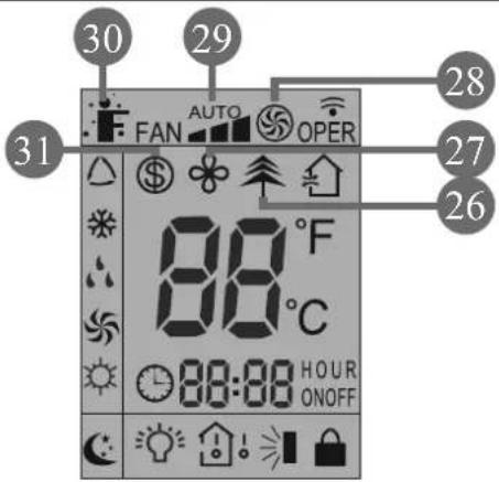
text_image
30 29 28 27 26 31 FAN AUTO OPER 88 °F C 88:88 HOUR ONOFF26 HEALTH icon:
is displayed when pressing the HEALTH button. Press this button again to clear the display. (optional)
29 FAN SPEED display:
Press FAN button to select the desired fan speed setting(AUTO-Low-Med-High).Your selection will be displayed in the LCD windows, except the AUTO fan speed.
27 X-FAN icon:
is displayed when pressing the X-FAN button Press this button again to clear the display. (optional)
30 I FEEL icon:
isdisplayed when pressing the I FEEL button. Press this button again to clear the display. (optional)
28 TURBO icon:
is displayed when pressing the
31 8°C Heating icon:
\$ is displayed when Pressing
again to clear the display.
nottubsihtsser" PortuabOBRLOCK" simultaneously in Heat mode (optional)

Operation of Remote Controller
Remote Controller Description
1 ON/OFF :
Press this button to turn on the unit .Press this button again to turn off the unit.
2 —:
Press this button to decrease set temperature. Holding it down above 2 seconds rapidly decreases set temperature. In AUTO mode, set temperature is not adjustable.
3 + :
Press this button to increase set temperature. Holding it down above 2 seconds rapidly increases set temperature. In AUTO mode, set temperature is not adjustable.
4 MODE :
Each time you press this button, a mode is selected in a sequence that goes from AUTO, COOL, DRY, FAN, and HEAT *, as the following:
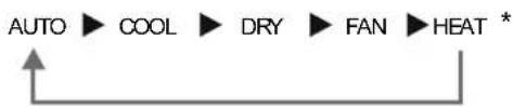
flowchart
graph LR
    A["AUTO"] --> B["COOL"]
    B --> C["DRY"]
    C --> D["FAN"]
    D --> E["HEAT *"]
*Note: Only for models with heating function.
After energization, AUTO mode is defaulted. In AUTO mode, the set temperature will not be displayed on the LCD, and the unit will automatically select the suitable operation mode in accordance with the room temperature to make indoor room comfortable.
5 FAN :
This button is used for setting Fan Speed in the sequence that goes from AUTO, , to , then back to Auto.

flowchart
graph LR
    A["Auto"] --> B["Low speed"]
    B --> C["Medium speed"]
    C --> D["High speed"]
6 SWING:
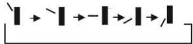
Press this button to set up &down swing angle.
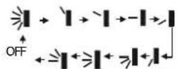
This remote controller is universal. If any command ≥slant 1 , ≥slant 1 or ≥slant 1 is sent out, the unit will carry out the command as ≥slant 1

indicates the guide louver swings as:
7 I FEEL:
Press this button to turn on I FEEL function. The unit automatically adjust temperature according to the sensed temperature at the remote to maximize your comfort. Press this button again to cancel I FEEL function.(optional)
8
Press this button to start the ventilatin system or generate cold plasma function. (The function is optional)

Operation of Remote Controller
9 SLEEP :
Press this button to go into the SLEEP operation mode. Press it again to cancel this function. This function is available in COOL, HEAT (Only for models with heating function) or DRY mode to maintain the most comfortable temperature for you.
10 TEMP:
Pressing TEMP button, ⏻ (set temperature), ⏻ (indoor ambient temperature) and ⏻ (outdoor ambient temperature) (This feature is applicable to only some models) and blank is displayed circularly .The unit defaults not to display the icon. During operation of Temp button, the set temperature is always displayed .
11 TIMER ON :
Press this button to initiate the auto-ON timer. To cancel the auto-timer program, simply press this button again.
After pressing this button, disappears and "ON" blinks .00:00 is displayed for ON time setting. Within 5 seconds, press + or - button to adjust the time value. Every press of either button changes the time settings by 1 minute. Holding down either button rapidly changes the time setting by 1 minute and then 10 minutes. Within seconds after setting, press TIMER ON button to confirm.
12 CLOCK :
Press CLOCK button ⏻ blinking. Within 5 seconds, pressing + or - button adjusts the present time. Holding down either button above 2 seconds increases or decreases the time by 1 minute every 0.5 second and then by 10 minutes every 0.5 second. During blinking after setting, press CLOCK button again to confirm the setting, and then ⏻ will be constantly displayed.
13 TIMER OFF :
Press this button to initiate the auto-off timer. To cancel the auto-timer program, simply press the button again. TIMER OFF setting is the same as TIMER ON.
14 TURBO:
Press this button to activate / deactivate the Turbo function which enables the unit to reach the preset temperature in the shortest time. In COOL mode, the unit will blow strong cooling air at super high fan speed. In HEAT mode, the unit will blow strong heating air at super high fan speed.
15 LIGHT:
Press LIGHT button to turn on the display's light and press this button again to turn off the display's light. If the light is turned on, 🔒 is displayed. If the light is turned off, 🔒 disappears.
16 X-FAN: (Auto Clean) (Optional)
Pressing X-FAN button in COOL or DRY mode, the icon ⚙ is displayed and the indoor fan will continue operation for 10 minutes in order to dry the indoor unit even though you have turned off the unit. This is to keep indoor coil clean + heathly. After energization, X-FAN OFF is defaulted. X-FAN is not available in AUTO,FAN or HEAT mode.

Operation of Remote Controller
17 Combination of "+" and "-" buttons: About lock
Press "+" and "-" buttons simultaneously to lock or unlock the keypad. If the remote controller is locked, is displayed. In this case, pressing any button, blinks three times.
18 Combination of "MODE" and "-" buttons: About switch between Fahrenheit and centigrade
At unit OFF, press "MODE" and "-" buttons simultaneously to switch between °C and °F.
19 Combination of "TEMP" and "CLOCK" buttons (optional): About Energy-saving Function
Press "TEMP" and "CLOCK" simultaneously in Cool mode to start energy-saving function. Nixie tube on the remote controller displays "SE". Repeat the operation to quit the function.
20
Press "TEMP" and "CLOCK" simultaneously in HEAT mode to Nixie tube on the remote controller displays" \$ " and a selected temperature of "8 ." (46°F if Fahrenheit is adopted). Repeat the operation to quit the function.
21 About Back-lighting Function
The unit lights for 4s when energizing for the first time, and 3s for later press.
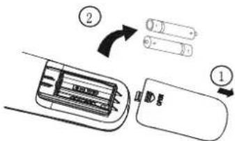
Replacement of Batteries
- Remove the battery cover plate from the rear of the remote controller. (As shown in the figure)
- Take out the old batteries.
- Insert two new AAA1.5V dry batteries, and pay attention to the polarity.
- Reinstall the battery cover plate.
Notes:
- When replacing the batt eries, do not use old or different types of batt eries, otherwise, it may cause malfunction.
- If the remote controller r will not be used for a long time, please remove batteries to prevent batteries from leaking.
● The operation should be performed in its receiving range. - It should be kept 1m away from the TV set or stereo sound sets.
- If the remote controller does not operate normally, please take the batteries out and reinsert them after 30 seconds. If it still can't operate properly replace the batteries.
text_image
Diagram showing battery cell components with labeled parts and directional arrows indicating movement or process.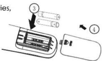
text_image
ies, ③ ④Sketch map for replacing batteries


natural_image
Simple rounded rectangle outline with no text, numbers, or symbols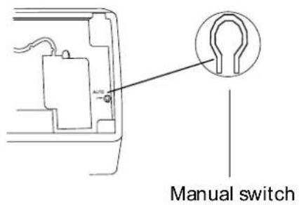
text_image
Manual switch


| ^ | |||
| ^ | |||
| ^ |


Clean and Care

Caution
● Disconnect the power supply before cleaning and maintenance.
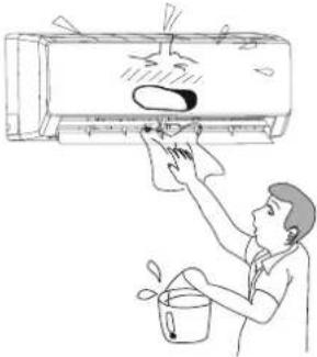
● Do not splash water on the units for cleaning, as electric shocks may occur
● Wipe the units with a dry soft cloth, or a cloth slightly moistened with water or cleaner (not with volatile liquid such as thinner or gasoline).
Cleaning the Front Panel
Remove the front panel. Dip a piece of cloth into the water colder than 45^ C and dry it. Then wipe the dirty part of front panel.
Note: Do not immerse the front panel into water so as to protect microcomputer components and circuit diagram on the front panel.
Cleaning the Air Filter (every 3 months)
Note: Do not to touch the fin of indoor unit during cleaning to avoid personal injury.
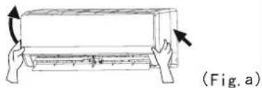
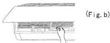
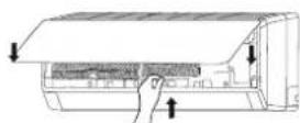
① Take down the air filter Lift up the front panel. Pull the air filter downwards to remove, as shown in Fig .(a,b).
natural_image
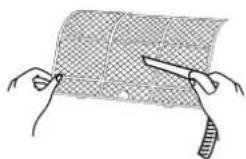
Illustration of a hand pressing down on a rectangular object with arrows indicating motion (no text or symbols)② Clean the air filter Use a vacuum cleaner to remove dust. If the filter are dirty, wash them with warm water and a mild detergent. Air Dry the filters in the shade.
natural_image
Diagram of a hand placing a component into an air conditioner unit (no text or symbols visible)Note: Never use water above 45 °C to clean the air filter or it can cause deformation or discoloration. it's good to change filters every 2 year. Contact your dealer or EcoAir.
③ Reinstall the air filter Reinstall the filters along the direction of arrowhead. Close the panel.

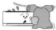
Check before use
① Be sure that nothing obstructs the air outlet and intake vents.
② Check that wiring are properly connected.
③
④ Check that whether the installation brackets of the outdoor unit are in good condition. If damaged, please contact the dealer.
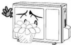
Maintain after use
① Turn main power off.
② Clean the filter and indoor and outdoor units' bodies.
③ Clear dust and obstructions from the outdoor unit.
④
⑤ Adopt the special shield to cover the outdoor unit, avoid the rain water, dust enter into the unit.


CAUTION
Don't attempt to repair the air conditioner by yourself, it can cause an electric shock or fire. Please check the following items before asking for repair, it can save your time and money.
| Phenomenon | Troubleshooting |
Not operate immediately when the air conditioner is restarted.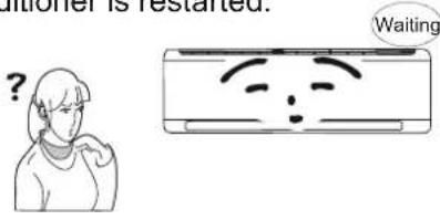 | ● Once the air conditioner is stopped, it will protect itself. |
There's unusual smell blowing from the outlet after operation is started.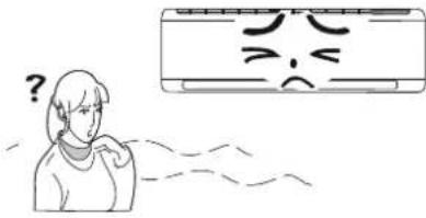 | ● The unit has no peculiar smell by itself. If it has that is due to the smell accumulated in the ambient.● Solution method: Cleaning the filter.If problem is still there, you need to service the air conditioner. (Please contact your deale or EcoAir.) |
Sound of water flow can be heard during the operation.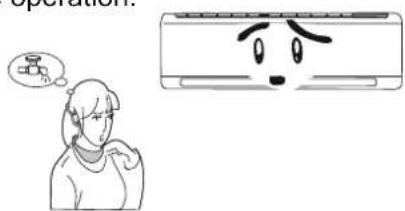 | ● The air conditioner is started, when it is running the compressor started or stopped running, or the unit is stopped, sometimes there is swoosh or gurgle, the sound is due to refrigerant flowing This is not a malfunction. |
In COOL mode, sometimes the mist emitted from the air outlet vent.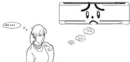 | ● When the indoor temperature and humidity are very high, this phenomenon would happen. This is caused by the room air is indoor temperature and humidity will fall down, the mist will die away. |
Creaking noise can be heard when start or stopping the unit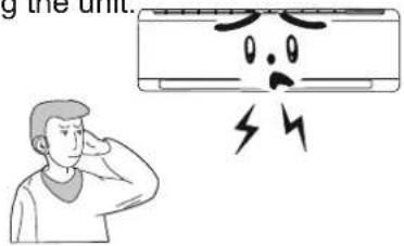 | ● This is caused by the deformation of plastic due to the changes of temperature. |

Troubleshooting
| Phenomenon | Troubleshooting |
The unit can not run.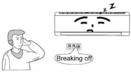 | Has the power been shut down?Is power plug loosed?Is the circuit protection device tripped off or not?Is voltage higher or lower?(Tested by qualified air conditioning engineer)Is the TIMER correctly used? |
Cooling(Heating) efficiency is not good.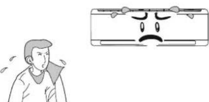 | Is Temp. setting suitable?Are inlet and outlet vents obstructed?Is filter dirty?Are the windows and doors closed?Is Fan speed set at low speed?Is there any heat sources in the room? |
Wireless remote control is not available.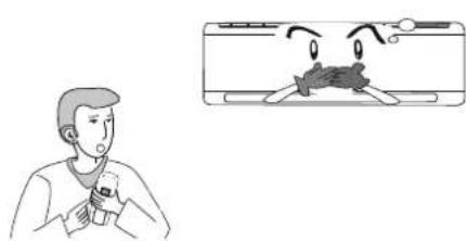 | The unit is interfered by abnormal or frequent functions switch over occasionally the controller cannot operate. Power down and remove power plug for 3 minutes, and then reinstate powerIs it in its receiving range? Or obstructed?replace the batteries in the remote control insideWhether the wireless remote control is damaged. |
| If water leakage in the room. | The air humidity is on the high side.Condensing water over flowed.The connection position of indoor unit drainage pipe is faultyPosition of drainage hose badly fitted. |
| If water leakage in outdoor unit. | When the unit is running in COOL mode, the pipe and connection of pipe would be condensed due to the water cooled down.When the unit is running in Auto Defrosting mode the ice thawed and flowed out.When the unit is running in HEAT mode, the water adhered on heat exchanger dripped off. |
| Noise from indoor unit emitted. The sound of fan or compressor relay is switching on or off.When the defrosting is started or stop running, it will sound. That is due to the refrigerant flowed to the reverse direction. | |

Troubleshooting
| Phenomenon | Troubleshooting |
| In HEAT mode, when the outdoor temperature is low or high humidity, frost will form on the outdoor heat exchanger, that the unit will automatically defrost, indoor unit stop blowing air for 3-12min.During the defrosting, there is water flowing out or vapor be produced.If unit is running under the high humidity for a long time, the moisture will be condensed on the air outlet grill and drip off. | |
 Immediately stop all operations and plug out, contact the dealer in following situations. Immediately stop all operations and plug out, contact the dealer in following situations. | |
There is an abnormal heat in power supply cord and power plug.  | |

Notices for installation

Important Notices
-
The unit installation work must be done by air conditioning engineer according to the local rules and this manual.
-
To avoid malfunction and warranty, installations must be carried out by qualified air conditioning engineers.
-
When removing the unit to the other place, please firstly contact with the authorized or qualified air conditioning engineer.
Basic Requirements For Installation Position
Install in the following place may cause malfunction. If it is unavoidable contact with service center please:
- Place where strong heat sources, vapors, flammable gas or volatile object are emitted.
- Place where high-frequency waves are generated by radio equipment, welders and medical equipment.
- Place where a lot of salinities such as coast exists.
- Place where the oil (machine oil) is contained in the air.
- Place where a sulfured gas such as the hot spring zones is generated.
● Other place with special circumstance.
Indoor Unit Installation Position Selection
- The air inlet and outlet vent should be far from any obstruction, make sure that the air can be blown through the whole room.
- Select a position where the condensing water can be easily drained out, and the place is easily connected for outdoor unit.
- Select a location where the children can not reach.
- Can select the place where is strong enough to withstand the full weight and vibration of the unit. And will not increase the noise.
- Be sure to leave enough space to allow access for routine maintenance. The height of the installed location should be 200cm or more from the floor.
- Select a place about 1m or more away from TV set or any other electric appliances.
- Select a place where the filter can be easily taken out.
- Make sure that the indoor unit installation are accordance with installation dimension diagram requirements.
- Do not use the unit in the immediate surroundings of laundry, bath, shower or a swimming pool.
Outdoor Unit Installation Position Selection
- Select a location from which noise and outflow air emitted by unit will not inconvenience neighbors, animals, plants.
- Select a location where there should be sufficient ventilation.
- Select a location where there should be no obstructions cover the inlet and outlet vent.
- The location should be able to withstand the full weight and vibration of the outdoor unit and permit safe installation.
- Select a dry place, but do not expose under the direct sunlight or strong wind.
- Make sure that the outdoor unit installation dimension should accordance with installation dimension diagram, convenient for maintenance and repairs.
- The height difference of connecting the tubing within 5m, the length of connecting the tubing within 10m.
- Select a place where it is out of reach for the children.
- Select a place where will not block the passage and do not influence the city appearance.
Safety Requirements For Electric Appliances
- The power supply should be used the rated voltage and AC exclusive circuit, the power cable diameter should be satisfied.
It should be reliably earthed, and it should be connected to the special earth device, the installation work should be operated by the qualified electricians. An electric spur and rotary isolator must be fitted in order to protect the short circuit and overloading.
Note:
wrong connection may cause fire.
Earthing requirements
- Air conditioner is type I electric appliance, thus please do conduct reliable earthing measure.
for other propose. It cannot be cut off and be fix it by screw, otherwise it would cause electric shock.
-
The earth resistance should accord to the National Criterion.
-
The user power must offer the reliable earthing terminal. Please don't connect the earthing wire with the following place:
①
②
③
④

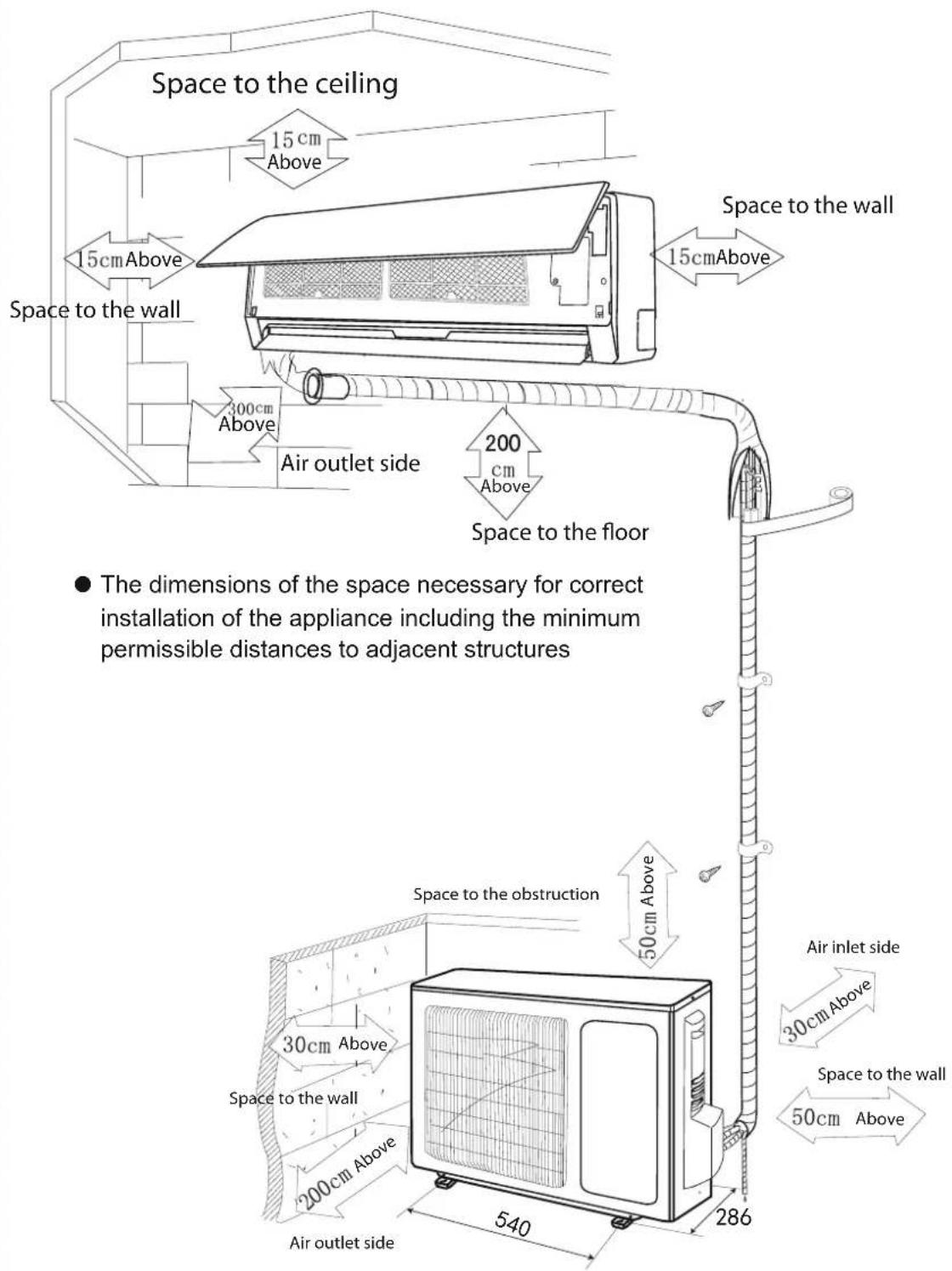
Installation dimension diagram
Installation dimension diagram
text_image
Space to the ceiling 15cm Above 15cm Above Space to the wall 300cm Above Air outlet side 200 cm Above Space to the floor ● The dimensions of the space necessary for correct installation of the appliance including the minimum permissible distances to adjacent structures Space to the obstruction 50cm Above Air inlet side 30cm Above Space to the wall 50cm Above Air outlet side 540 286
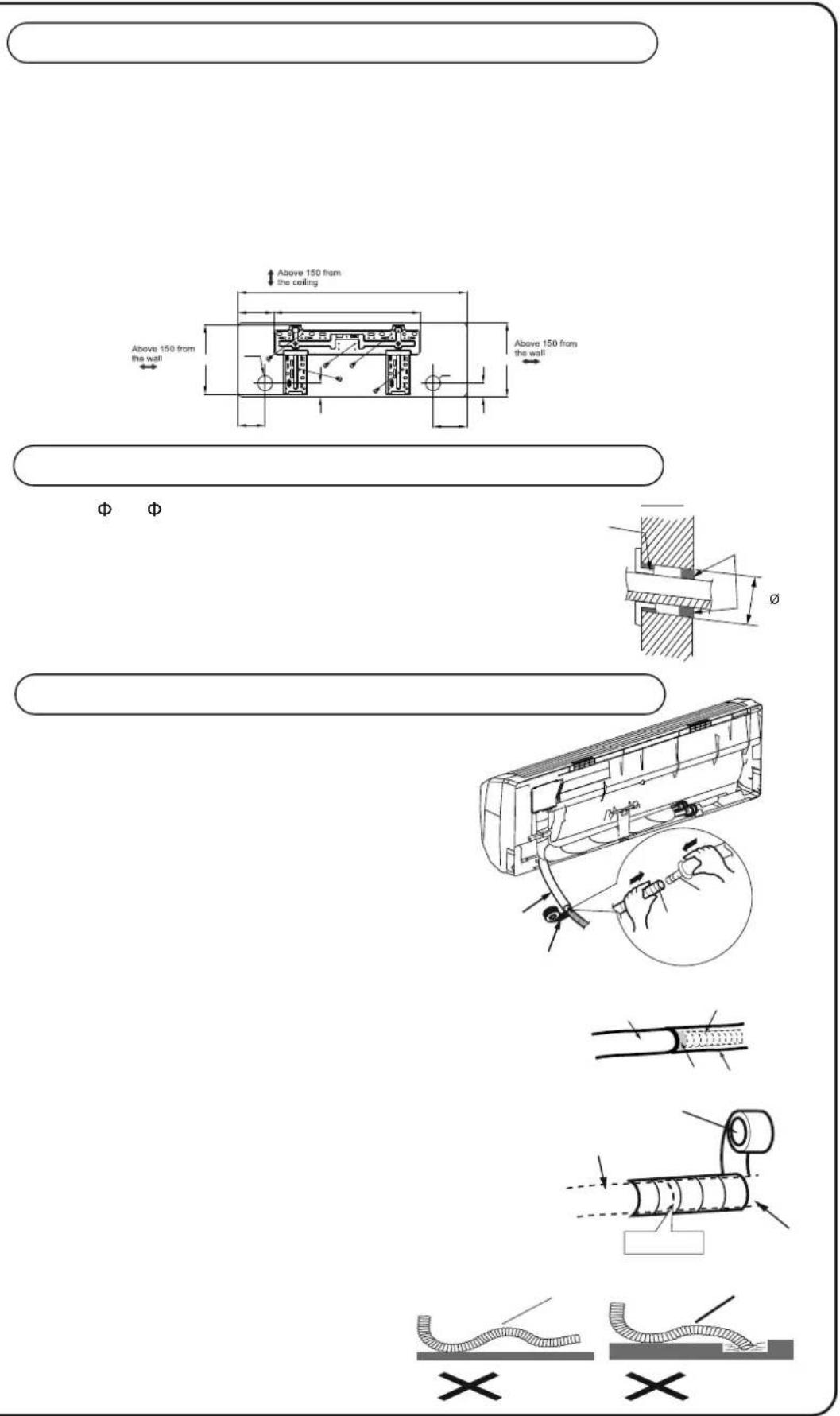
text_image
Above 150 from the wall Above 150 from the ceiling Above 150 from the wall Φ Φ Ø X X
Installation of Indoor Unit
Connecting Indoor and Outdoor Electric Wires
1.Open the front panel.
2. Remove the wiring cover as shown in Fig 6.
- Reinstall the front panel.
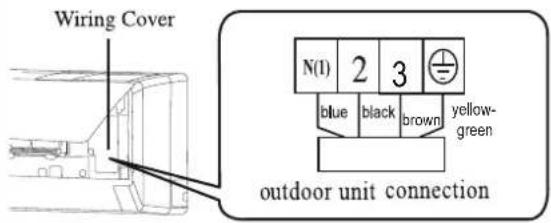
text_image
Wiring Cover N(1) 2 3 blue black brown yellow- green outdoor unit connectionFig.6
NOTE:
All wires between indoor and outdoor units must be connected by the qualified electric air conditioning engineer.
- Electric wires must be connected correctly. Improper connection may cause malfunction.
- Tighten the terminal screws tightly.
• After tightening the screws, pull the wire slightly to confirm whether it's firm or not.
• Make sure that the electric connections are earthed properly to prevent electric shock. - Make sure that all wiring connections are secure and the cover plates are reinstalled properly. Poor installation may cause fire or electric shock and malfunctions, which is not cover by warranty

Installation of Indoor Unit
Installation of Indoor Unit
● The piping can be output from right, right rear, left or left rear.
1. When routing the piping and wiring from the left or right side of indoor unit, cut off the tailings from the chassis when necessary( As s hown Fig.7)
(1) Cut off the tailings 1 when routing the wiring only;
(2) Cut off the tailings 1 and tailings 2 when routing both the wiring and piping.
- Take out the piping from body case, wrap the piping power cords, drain hose with the tape and then make them pass through the piping hole (As shown in Fig.8)
- Hang the mounting slots of the indoor unit on the upper hooks of the mounting plate and check if it is firm enough.(As shown in Fig.9)
- The installation site should be 200 cm or more above the floor.
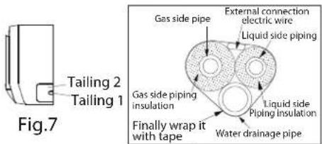
text_image
Fig.7 Tailing 2 Tailing 1 Gas side pipe External connection electric wire Liquid side piping Gas side piping insulation Liquid side Piping Insulation Finally wrap it with tape Water drainage pipe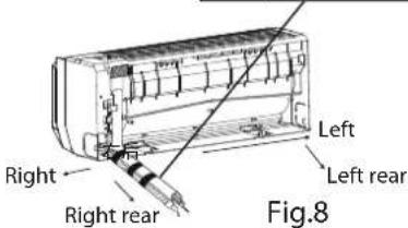
text_image
Right Right rear Left Left rear Fig.8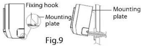
text_image
Fixing hook Mounting plate Mounting plate Fig.9Installation of Connection Pipe
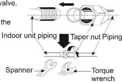
- Align the center of the piping flare with the related valve.
- Screw in the flare nut by hand and then tighten the nut with spanner and torque wrench by referring to the following:
| Hex nut diameter | Lightening torque(N·m) |
| Φ6 | 15~20 |
| Φ9.52 | 30~40 |
| Φ12 | 45~55 |
| Φ16 | 60~65 |
| Φ19 | 70~75 |
text_image
valve. the Indoor unit piping Taper nut Piping Spanner Torque wrenchNOTE: Connect the connection pipe to indoor unit at first and then to outdoor unit Handle piping bending with care. Do not damage the connection pipe. Ensure that the joint nut is tightened firmly, otherwise it may cause leakage of refrigerant gas because of poor installation is not covered under warranty.

Installation of Outdoor Unit
Electric wiring
-
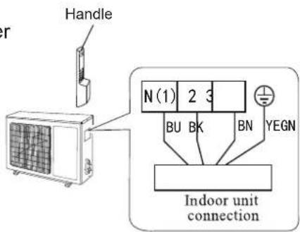
Disassemble the handle on the outdoor unit right side plate.
-
Take off wire clamp. Connect and fix power connect cord (for cooling and heating unit, connect and fix power connect cord and signal control wire) to terminal of line bank. Wiring should fit that of indoor unit.
-
Fix the power connection cable with wire clamp, (for cooling and heating unit, use the wire clamp to fix the power connection cable and the signal control wire), then connect the corresponding connector.
-
Ensure wire has been fixed well.
-
Install the handle.
text_image
Handle N(1) 2 3 BU BK BN YEGN Indoor unit connectionNOTE:
● Wrong wiring will cause parts malfunction.
● Make sure cables after connection and clamped, there is slack for any movement.
Air purging and leakage test
-
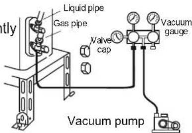
Connect charging hose to manifold valve at low pressure valve (both high/low pressure valves must be tightly shut).
-
Connect joint of charging hose to vacuum pump.
-
Fully open handle of Lo manifold valve.
-
Open the vacuum pump to evacuate. At the beginning, slightly loosen joint nut of low pressure valve to check if there is air coming inside. (If noise of vacuum pump has been changed, the reading of multimeter is 0) Then tighten the nut.
-
Keep evacuating for more than 15mins and make sure the reading of multi-meter is -1.0 × 10^5 pa (-76cmHg).
-
Fully open high/low pressure valves.
-
Remove charging hose from charging end of low pressure valve and refit dust valve Cap (as shown in the Fig 10)
text_image
Liquid pipe Gas pipe Valve cap Vacuum gauge Vacuum pumpFig. 10
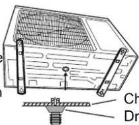
Condensate drainage of outdoor unit (no for cooling only)
The condensate and defrosting water formed during heating in the outdoor unit can be properly discharged by drainage pipe.
Installation method: set the drain connection in ∅ 25 hole of the chassis has been installed and then connect drainage pipe with drain nozzle, so that condensate and defrosting water can be properly discharged
text_image
Ch DrChassis Drain connection

Check after installation and test operation
Check after installation
| Items to be checked Possible malfunction | |
| Has it been fixed firmly? | The unit may drop, shake or emit noise. |
| Have you done the refrigerant leakage test? | It may cause insufficient cooling(heating) capacity |
| Is heat insulation sufficient? | It may cause condensation and dripping. |
| Is water drainage well? | It may cause condensation and dripping. |
| Is the voltage in accordance with the rated voltage marked on the nameplate? | It may cause electric malfunction or damage the part. |
| Is the electric wiring and piping connection installed correctly and securely? | It may cause electric malfunction or damage the part. |
| Has the unit been connected to a secure earth connection? | It may cause electrical leakage. |
| Is the power cord specified? | It may cause electric malfunction |
| Is the inlet and outlet been covered? It may cause insufficient cooling(heating) capacity. | |
| Has the length of connection pipes and refrigerant capacity been recorded? | The refrigerant capacity is not accurate. |
Test Operation
- Before test operation
(1) Do not switch on power before installation is finished completely.
(2) Electric wiring must be connected correctly and securely.
(3) Cut-off valves of the connection pipes should be opened.
(4) All the impurities such as scraps and packaging must be cleared from the unit.
- Test operation method
(1) Switch on power, press "ON/OFF" button on the wireless remote control to start the operation.
(2) Press MODE button, to select the COOL, HEAT (Cooling only unit is not available), FAN to check whether the operation is normal or not.
ONE (1) YEAR LIMITED WARRANTY Save This Warranty Information
Eco Air guarantees this product free from defects in materials and workmanship for a period of one (1) year from the date of purchase. Coverage is valid only with proof of purchase.
Faults arising from a faulty installation is specifically excluded.
This unit must be operated under conditions as recommended, within the voltage range indicated on the unit. Any attempts made to service or modify the unit, will render this WARRANTY VOID. The actual product may differ slightly from the illustration. This warranty is in addition to, and does not affect, your statutory rights.
If the unit is modified or mis-used, this could void the warranty.
For further information, please contact 0845 388 0007.
This product has been manufactured to comply with the EC Directives 2006/95/EC and 2004/108/EC.
We recommend that you note the details of your purchase below and retain your original proof of purchase / receipt with this manual. Keep these documents safe in the event of a warranty claim.
Date of purchase: ____
Retailer name: ____
Serial number: ____