SunVision 466 XXL - Solarium Alisun - Free user manual and instructions
Find the device manual for free SunVision 466 XXL Alisun in PDF.


User questions about SunVision 466 XXL Alisun
0 question about this device. Answer the ones you know or ask your own.
Ask a new question about this device
Download the instructions for your Solarium in PDF format for free! Find your manual SunVision 466 XXL - Alisun and take your electronic device back in hand. On this page are published all the documents necessary for the use of your device. SunVision 466 XXL by Alisun.
USER MANUAL SunVision 466 XXL Alisun
text_image
CS Doktor SunООО "Доктор-Сан"
SunVision 400 series
BY ALISUN
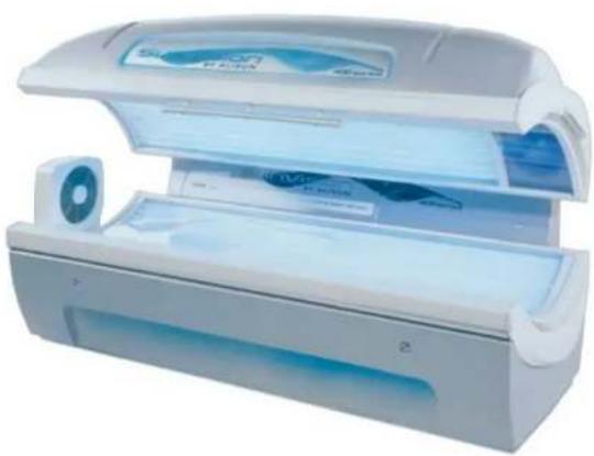
natural_image
Product photo of a white and blue hair dryer with open lid (no visible text or symbols)GB Manual
NL Handleiding ( 34)
D Bedienungsanleitung (→ 67)
F Instructions (→ 102)
E Manual ( → 137)
• SUNVISION 422 XXL - SOFT INTENSIVE POWER
• SUN VISION 433 XXL - DUOTAN POWER
• SUNVISION 444 XXL - TRUETAN POWER
• SUNVISION 466 XXL - TRUETAN POWER 160 WATT
document: SUNVISION 400
art: 382247
init: 2001/08
rev: 2003/05
5REWORD
You have made an excellent choice in purchasing a SUNVISION 400. The SUNVISION 422, 433, 444 and 466 sunbeds are the result of years of development work and careful manufacture. The SUNVISION 400-SERIES are designed to be as user friendly as possible and, of course, comply fully with all applicable European safety requirements. We ask that you read these instructions carefully: For the safety of your guests and to ensure that you enjoy your SUNVISION sunbed for as long as possible.
This manual provides the information you will need to install, program and maintain a sunbed from the SUNVISION 400-SERIES. This manual also contains general information that each studio owner will find useful.
Each SUNVISION 400 comes with an instruction poster. This explains to the user of the SUNVISION 400 how he or she can achieve safe and effective tanning with the sunbed.
SERIAL NUMBERS
Make a note of the serial numbers of your SUNVISION 400 below. You will need these if you contact your supplier with questions.
Both the bench and the canopy have their own serial number. You will find the manufacturer's stickers with the serial numbers on the back, at the end of the profiles. The serial numbers are also mentioned on the stickers on both sides of the cardboard boxes.
Bench
serial number
Canopy
serial number
CONTENTS
F OREWORD....2
SERIAL NUMBERS....2
TECHNICAL VARIATIONS....3
INTRODUCTION TO THE SUNVISION 400-SERIES ....3
PREPARATION....5
HOW IS THE SUNVISION 400 PACKED....7
POSITIONING....7
ASSEMBLY PARTS....7
ASSEMBLY 10
PROGRAMMING 17
OPERATION....20
TANNING WITH THE SUNVISION 400-SERIES....23
MAINTENANCE....27
READING OUT SERVICE DATA....29
COINBOX AND RECEPTION CONTROL SYSTEM 30
TROUBLESHOOTING 31
PARTS LIST....32
ENVIRONMENT 33
DECLARATION OF ONFORMITY 33
GUARANTEE CONDITIONS ....33

text_image
CS Doktor SunООО "Доктор-Сан"
A sunbed from the SUNVISION 400-SERIES consists of a canopy and a bench. To make it a complete sunbed, the canopy and the bench must be combined with the other parts and be assembled on site.
The UNVISION400-SERIES consists of four types:
- the UNVISION 422 canopy has 32 (16x2) 55 Watt PL-L 55cm low-pressure face tanner tubes and 18 Brilliant Sun plus R-XT 100 Watt (UV-type3), or 18 Brilliant Sun R-Intensive 100 Watt (UV-type 4), 1,80 metre tubes as standard.
- the UNVISION 433 canopy has 18 SunVision XTR 200 DuoTan 180 Watt 2,00 metre tubes as standard.
- the SUNVISION 444 canopy has three 320 Watt SE high-pressure face tanners with parabolic reflectors and 18 Brilliant Sun plus R-XT 100 Watt (UV-type3), or 18 Brilliant Sun R-Intensive 100 Watt (UV-type 4), 1,80 metre tubes as standard.
- the SUNVISION 466 canopy has three 400 Watt SE high-pressure face tanners with parabolic reflectors and 18 Cosmolux VHR4 160 Watt 1,80 metre tubes as standard.
- The bench of the SUNVISION 400-SERIES has 18 SUNVISION XTR 200 Plus 120 Watt 2 metre tubes as standard..
Variations are listed with the type.
Colours
Basic colours for the UNVISION 400-SERIES are: Titanium Silver, Cool White and Pearl White
Accents for the UNVISION 400-SERIES: Mystic Blue
Approval
All SUNVISION tanning equipment has been comprehensively inspected and awarded the following seals of approval:
EMC
• Key-mark (TÜV)
- CE mark
SUNVISION 400
INTRODUCTION TO THE SUNVISION 400-SERIES
The SUNVision tanning equipment belongs to the top end of the professional market and is manufactured by Alisun Europe B.V. The SUNVISION 400 is a modern sunbed from the SUNVision line and has an excellent price / quality ratio.
Features
The SUNVISION 400-SERIES comes with a number of standard built-in features. The 200-cm long 120-Watt lighting tubes in the bench are one such standard feature of the SUNVISION 400-SERIES and all types are fitted with the unique ergonomically shaped acrylic sheet. Its blue quiet-time lighting, the illuminated display in the canopy and the floodlight in the bench are also standard features.
Options
In addition to the standard functions the UNVISION 400-SERIES can also be supplied with different tube options for the canopy. The following types of lighting tubes are available as an option for the SUNVISION 422 XXL and the SUNVISION 444 XXL:
Cosmolux RCS 100 Watt
- Brilliant Sun Intensive 100 Watt
- Brilliant Sun R Intensive 100 Watt
Accessories:
The following accessories for the SUNVISION400 are available from your distributor:
- Reception control system (multiple)
- Reception control system (single)
- Coin box
- Coins
part no.: 356565+337340
part no.: 356590
part no.: 355134
part no.: 355132


ООО "Доктор-Сан"
durable. The powerful 120W tubes in the bench which are 200 cm long also make it possible for taller people to tan all over.
The powerful 320W and 400W SE TrueTan ^® face tanners are fitted with a special parabolic reflector in combination with extremely advanced filtering technology. This technology allows the maximum amount of UV-B to penetrate while eliminating undesirable heat. Naturally these face tanners are adjustable and safeguarded from unexpected overheating. Safety is a priority.
Unique Soft Intensive System (SIS ^® ) low-pressure face tanners with 55 cm long 55W PL-L tubes guarantee comfortable tanning that is kind to the skin and emit even less heat than the high-pressure variety. The low-pressure face tanners are also adjustable from the operating panel. More information about this can be found in the chapter 'OPERATION'.
The DuoTan tubes guarantee comfortable tanning that is kind to the skin and emit even less heat than the high-pressure face tanners.
Cooling
Powerful flow fans in combination with the vents at the head and foot of the bench and the canopy ensure a long life and maximum output as far as the lighting tubes are concerned. Because tube and body cooling are separate from each other the SUNVISION 400 has sublime cooling. The warm air from the lamp cooling is discharged directly to the outside and does not pass along the body. Air from the outside is drawn in so that the client is cooled with 'fresh air' and not with air that has already been warmed by the tube cooling. The level of body cooling can be adjusted in increments and can therefore be set to each user's liking. The setting can be read off the control panel.
Control panel
The operating panel of the SUNVISION 400 is located in the end piece above the face tanners which makes it easy for everyone to read. The unit is simple to operate with the aid of the clear touch keys. See the 'OPERATION' chapter for more information on the control panel.
Safety
The reliable technology of the SUNVISION 400 ensures optimal continuity. Each SUNVISION 400 satisfies the European standards and tests and is fitted with the Active Safety Monitoring System as standard; a powerful processor that continuously monitors all main relays. In the event of a fault the tubes are immediately switched off and the cooling is automatically initiated.
Comfort
During the development of the SUNVISION 400 SERIES explicit consideration was given to user comfort. All designs are fitted with a powerful body cooler for optimal refreshment while opening and closing the canopy requires only a light touch on account of the well-balanced gas springs. The height of the bench and the generous opening of the canopy make it easy for the user to lie down. The reclining comfort of SUNVISION 400 is truly incomparable thanks to the ergonomically shaped acrylic sheet which relieves a great deal of the pressure. The electronic operation is extremely simple and all information is visible at a glance on a clear digital display.
Studio control
The SUNVISION 400 is furnished with a separate coin box and reception control connection, in an easily accessible location. Naturally, with the option of installing the Alisun reception control and coin box with full control over the sunbed. See the chapter "COIN BOX AND RECEPTION CONTROL SYSTEM" for more information.
Quality
The SUNVISION 400-SERIES is manufactured from high-quality materials to give the maximum possible lifetime. It is based upon a sturdy aluminium construction with steel cross-bracing. The use of top quality plastics with special UV blockers gives the SUNVISION 400's plastic parts high UV-stability.
Maintenance
One of the most important points when developing the SUNVISION 400 was to make it service and maintenance-friendly. By opening the two locks the entire front panel of the SUNVISION 400 can be removed all at once which creates generous access for servicing. The electrical components are all within easy reach and where necessary can be lifted out of the sunbed for servicing and maintenance. All ballast units and other parts are of an easily manageable size.

text_image
CS Doktor SunООО "Доктор-Сан"
The SUNVISION 400 is an advanced sunbed, which can provide years of trouble-free use. But first of all we would like to bring a number of points to your attention.
Foundation
It is important for the correct functioning of the SUNVISION 400 that the floor on which it stands is level and can bear the weight of the sunbed. We recommend that the floor is made of a hard material such as parquet, laminate, linoleum or a synthetic cast floor. When choosing the floor covering, bear in mind that you will need to be able to clean the floor thoroughly on a regular basis.
Cabin dimensions
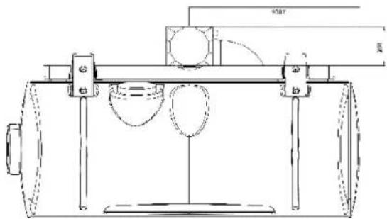
The recommended minimum cabin dimensions for positioning the SUNVISION 400 are 2.40 x 2.30 m (LxW). A drawing with dimensions can be found at the end of this chapter.
Air extraction system
The SUNVISION 400 has one external air exhaust outlet, which extracts the air from the canopy and the bench. It is important that the diameter is kept at ∅250mm for effective air extraction. A smaller diameter means less effective cooling as well as the likelihood of damage and wear and tear through overheating. Before connecting a tube or hose to the flow fan the grill cover first needs to be removed. It is advisable to use a separate tube or hose leading directly to the outside.
For effective ventilation it is important that the flow fan is able to extract the air with as little counterpressure as possible. The counterpressure of the material used (a smooth tube or a ribbed flexible hose) will therefore determine the maximum length and the number of bends of the outlet. The table below shows what sort of material produces what sort of resistance. The maximum counterpressure of the fan for the SUNVISION 400 is determined at 260 Pascal. The average counterpressure must be between 100 and 250 Pa. The minimum counterpressure is also an important consideration. When the counterpressure is too low the appliance becomes warm and uses up more electricity than necessary. A simple calculation enables you to work out which combination of outlet material is appropriate for your situation.
SUNVISION 400
| Type of outlet material | Counterpressure (in Pa) |
| Tube smooth 250mm (1 metre) | 8 |
| 90^a Bend smooth 250mm | 40 |
| 45^a Bend smooth 250mm | 20 |
| Hose flexible 250mm (1 meter) | 40 |
| 90^a Bend flexible 250mm | 150 |
| 45^a Bend flexible 250mm | 73 |
| 100% Throughflow cover | 15 |
Example: The outlet needs to go straight up for 2 metres, then make a 90^ left turn above the ceiling, followed by another bend at 90^ towards the back, finally extending another metre through the wall to the outside through a cover that allows 100% troughflow. If a smooth outlet tube is used, the fan for a situation such as this would need a counterpressure of 8 + 8 + 40 + 40 + 8 + 15 = 119Pa . The result is proper ventilation and effective cooling. When using a flexible outlet hose, the counterpressure works out at: 40 + 40 + 150 + 150 + 40 + 15 = 435Pa . This counterpressure is well above the maximum counterpressure for the fan (260 Pa.).
If you have any questions about the correct outlet for your situation, please contact your distributor who will be pleased to give you further assistance. If you wish to connect several beds to a single outlet, you would be well advised to consult a ventilation expert. Make sure that a connection is already present before the sunbed is put in place. A drawing showing the exact measurements in detail can be found at the end of this chapter.
Air supply
The air from the surrounding area is used to cool the tubes of the SUNVISION400. The body cooling also uses the air from the surrounding area. Because the SUNVISION400 has an external air supply connection, it is important that there is an adequate supply of fresh air.
The rule of thumb normally applied is that no less than 3x the surface area of the air vent must be able to flow freely into the area to avoid draught problems. The surface size of the air intake in this case would need to be not less than 0.59m^2 .


ООО "Доктор-Сан"
Before the sunbed can be put in place, a suitable power supply must be present in the cabin. The SUNVISION 400 requires a power supply of 230/400V 3N\~50Hz and a wall socket CEE Form 16A 5-pole.

Plug

Wall socket fitting

Wall socket extension
◆ Reception control and coin box
If a reception control system or a coin box is required the necessary wiring must be present before the sunbed is put in place. Connection information can be found in the chapter entitled 'COIN BOX AND RECEPTION CONTROL SYSTEM'.
Failure to follow these instructions correctly will delay installation and may lead to the equipment being damaged during use.
◆ Technical values
| SUNVISION | 422 4344 46 | |
| Connection value | 230/400V 3N~50Hz | |
| Minimum fuse (slow) | 3x16A | |
| Power in kW | 5.3 6.0 6.5 7.6 | |
| Air displacement central exhaust system (m3/hour) | 2550 | |
| Maximum air displacement Body Cooler (m3/hour) | 1815 | |
| Maximum dimensions in mm (L x W x H) | 2275 x 1232 x 1526 | |
| Weight in kilograms | 230 25236 240 | |
Dimensions

text_image
CS Doktor Sun000 "Доктор-Сан"
natural_image
Technical line drawing of a mechanical component with curved surfaces and a central circular feature (no text or symbols)05/2003
text_image
Technical diagram of a mechanical device with labeled components and motion indicators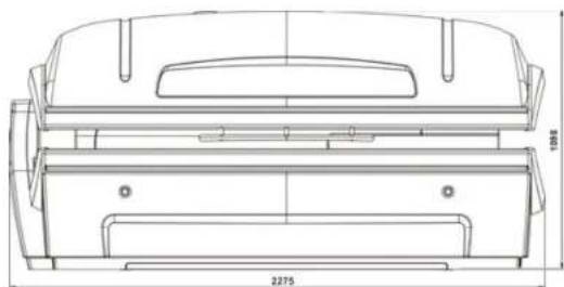
natural_image
Technical line drawing of a two-part car chassis with side panels and front panel (no text or symbols)

ООО "Доктор-Сан"
The SUNVISION 400 comes packed in eight cardboard boxes numbered according to their assembly sequence. The first box contains the two legs making up the stand. The second box contains the rear wall, the metal sections of the pedestal frame, plastic parts, the cushion and items required for the assembly. Packed into the third box is the complete fan unit including air hoses for the canopy and bench as well as fastenings. The fourth box contains the bench. The fifth box has the canopy with the support arm already fitted, the stickers, the handle and the wires and fixture for the floodlight. The sixth box contains the body cooler and the ballast units are packed into boxes seven and eight.
◆ Unpacking and checking
Please check immediately at delivery if the SUNVISION 400 has been delivered to you complete and undamaged. If necessary, open the boxes and check the contents for visible damage. Inform the transport company immediately of any visible damage.
POSITIONING
Your SUNVISION 400 will have undergone high voltage, earth resistance and functionality tests in the factory. It is however still possible that your SUNVISION 400 may appear not to work, or not to work properly, after connection. In this event first read the 'TROUBLESHOOTING' chapter.
In order to quickly find solutions to faults in your specific SUNVISION 400 it is a good idea to have the serial numbers to hand when you contact your supplier. We recommend that you note the serial numbers on the first page of this manual so that it is to hand if you need it.
Environment
We have described the environmental requirements for optimal, safe and hygienic tanning in the 'PREPARATION' chapter.
The SUNVISION 400 is delivered in separate components and must be assembled on site. Take into account the space required to put down all the separate components.
FASTENING PARTS

Socket-head screw M6x10
3x
part number: 370510
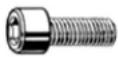
Socket-head screw M8x25
10x
part number: 370523
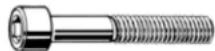
Socket-head screw M8x60
2x
part number: 370530

Socket-head screw M8x80
4x
part number: 370534

Socket-head screw M8x110
1x
part number: 370538
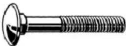
Carriage bolt M10x60
2x
part number: 370570

Metal screw M5x50
3x
part number: 370247
SUNVISION 400


000 "Доктор-Сан"
Tapping screw 4.8x9.5
22x part number: 370099
Tapping screw 4.8x25
2x part number: 370104

Tapping screw 6.3x13
5x part number: 370113
Chipboard screw 4.5x17
10x part number: 370804
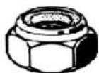
Self-locking nut M8
2x part number: 370621
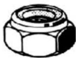
Self-locking nut M10
2x part number: 370622
Washer M6
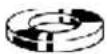
3x
part number: 370643
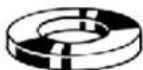
6x
part number: 370644
Washer M8
Washer M10
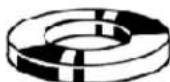
2x
part number: 370645

Panel washer M8x30x1.5
4x
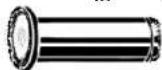
2x
part number: 370713
Fork shaft M10x40
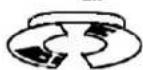
2x
part number: 346820
Fork clip M10x40
part number: 346819
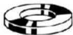
4x
part number: 337621
Nylon washer 10.2x17x2


4x
part number: 336116
Nylon spacer
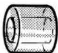
4x
part number: 337611
End insert
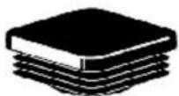
4x
part number: 337198
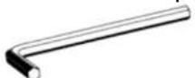
1x
part number: 371004
Hex key 4mm
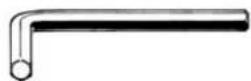
1x
part number: 371000
Hex key 6mm
Hex key 5mm
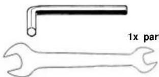
natural_image
Simple line drawing of a wrench and a flat wrench (no text or symbols)1x part number: 371002
Open-end spanner13/17mm
1x
part number: 371011
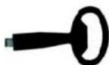
1x
part number: 370971
Bench key, square 6mm


000 "Доктор-Сан"
This chapter provides a step by step description of the assembly process. We recommend that you read through the entire chapter before starting with the assembly.
Before commencing please check that the voltage at your location is the same as that indicated on the type plates on the canopy and bench.
We recommend that when you commence the assembly you leave sufficient distance from the wall to provide access to the back.
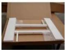
Open box 1 and remove the legs of the stand from the packaging.
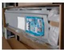
Also open box 2 and take out the blister pack with the fastening items. Save the styrofoam blocks. They are needed for the assembly of the canopy.
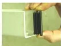
Put the end inserts into the floor-end of the legs of the stand (4x).
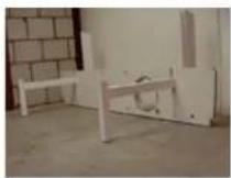
Next put the wooden back wall in place.

Doktor Sun
000 "Доктор-Сан"
Secure it to the legs of the stand with four socket-head screws (M8x25).
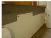
Position the steel seal plate at the top of the back of the back wall and secure with the 6 chipboard screws (4.5x17).
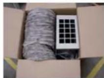
Next the flow fan (from box 3) can be mounted to the back wall.
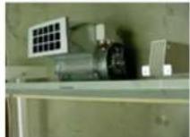
Put the flow fan in place and secure to the back wall with 4 washers (M8) and 4 socket-head screws (M8x25). Don't tighten the nuts too much.
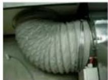
Position the short air hose between the flow fan and the back wall and secure at both ends with the hose clips provided. The remaining ends of the hose clips can be cut off.
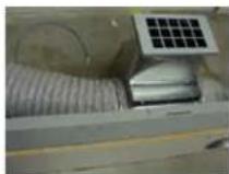
Also secure the long air hose for the canopy to the flow fan with the hose clip provided.
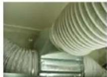
If the appliance is being connected to an external exhaust, the grill cover can now be removed from the top of the flow fan. Place the air exhaust hose over the outlet and fasten with a hose clip.
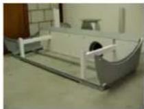
Next assemble the frame for the pedestal. Lay all the parts in their correct positions and first of all fasten the short support profiles with the plastic side covers on the left and the right-hand sides of the back wall.
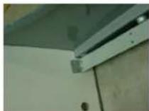
To do this use 4 chipboard screws (4.5x17). Remove the protective film from the plastic end pieces.
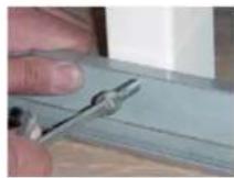
Fasten the complete support profile to the front of both legs of the stand. To do this use 2 socket-head screws (M8x25).

Secure the front support profile to the side profiles on the left and the right using 4 tapping screws (4.8x9.5).
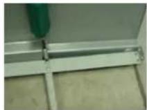
Secure the support profile in the centre to the side profiles on the left and the right using 4 tapping screws (4.8x9.5).
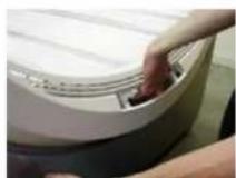
The bench can now be put in place. Open box 4. By pulling the small cover away from the end piece carefully with a screwdriver you can hold on to the bench and move it more easily.
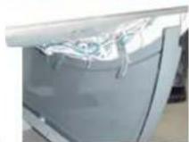
Place the bench carefully over the side covers and ensure that the side covers are wedged firmly between the inside of the end piece and the metal holding clips.

text_image
CS Doktor Sun000 "Доктор-Сан"
Place the bench with its location braces onto the legs of the stand. The holes in the braces must be aligned exactly with the holes in the legs. Secure the bench to the legs using 4 panel washers (M8x30x1.5) and 4 socket-head screws (M8x80).
Next fasten the steel seal plate from the back wall to the profile of the bench. To do this use 5 tapping screws (6.3x13).
Now open the box containing the canopy (box 5).
On both sides place the two nylon slide bearings in the hinge point of the support arm.
Take the two styrofoam pieces out of the box and lay them on the bench as support for the canopy. Now lay the canopy on the styrofoam pieces and place the support arm with the hinge points into the frame.
n
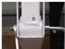
Secure it on both sides using 2 socket-head screws (M8x60), 2 washers (M8) and 2 self-locking nuts (M8).t tighten the nut on the side of the ring too much.
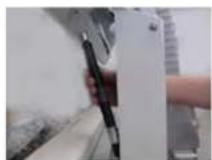
Remove the two gas springs from box 6 and secure these onto both legs of the stand. Make sure when doing this that the narrow section of the gas spring with the rings on it points down.
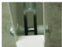
Put the carriage bolt (M10x60) from the outside to the inside through the middle hole in the legs of the stand and next place on it a nylon spacer (10.3x15x7.5), the fork with the complete gas spring and another nylon spacer (10.3x15x7.5). Secure the items together to the inside of the leg with the washer (M10) and the self-locking nut (M10).
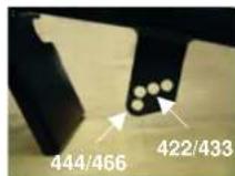
Now lift up the canopy and fasten the gas springs to the hinge arm. Put the shaft through the fork and through the right hole of the fastening plate. At this point it is important to check whether the canopy springs in all its positions as it should. If this is not the case, it is possible to change the position of the gas springs.
If the canopy goes up by itself, the lower section of the gas springs on both sides needs to be moved to the frontmost hole of the legs of the stand.

text_image
CS Doktor Sun000 "Доктор-Сан"
Place two additional nylon washers (10.2x17x2) on both the gas springs (on each gas spring there will now be a total of four nylon washers and one rubber ring) and twist the forks back onto them. Now secure the gas springs to both sides in the fastening plate again.
If the canopy comes down by itself, move the lower section of the gas spring to the rearmost hole in the legs of the stand.
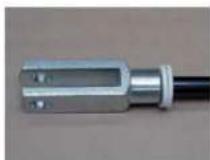
Remove the rubber ring from both the gas springs (there is now a total of only two nylon washers on each gas spring) and return the forks. Secure the gas springs to both sides back in the fastening plate.
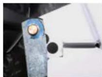
Finally slide the clip over the end of the shaft till it is held firmly in place.
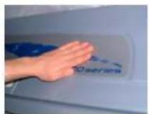
Remove the protective film off the cover for the gas springs. Take the name and type stickers from box 5 and stick them on the cover for the gas springs in the indentations for that purpose. Press the stickers on firmly and rub over them with a clean cloth to remove any bubbles.
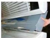
Lift the canopy up and place the covering plate for the gas springs face up behind the canopy.
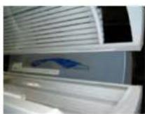
Press the lower edge of the cover to the back and allow it to drop into the five grooves in the steel seal plate of the back wall.
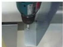
Secure the cover for the gas springs on both sides to the steel seal plate. To do this use 2 tapping screws (4.8x9.5).
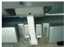
Also secure it to the top of the legs of the stand. To do this use 2 tapping screws (4.8x9.5).

Doktor Sun
ООО "Доктор-Сан"
Remove the protective film from the covers for the support and fix the covers on the support arm. To do this use 2 tapping screws (4.8x9.5) and 2 tapping screws (4.8x25). Make sure that the canopy cord stays tucked behind the cover.
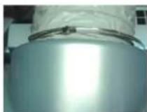
Now attach the hose to the back of the canopy. Fix it in place with a hose clip.
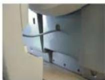
Next place the body cooler at the foot of the bench, feed the power cord through the hole for that purpose in the side cover.
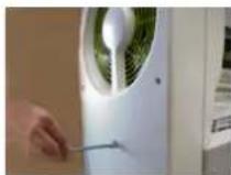
Secure the body cooler to the end piece using a socket-head screw (M8x110). Don't tighten the screw yet.
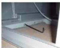
Also secure the body cooler to the pedestal frame using 3 washers (M6) and 3 socket-head screws (M6x10). The M8 screw can now be tightend.
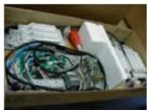
Next open box 7 and get the power cord out of the box.
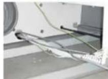
Feed this power cord also through the hole in the back wall for that purpose.
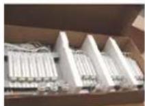
The bed can now be lifted or pushed back and placed in the correct position. This should be done with care to avoid scratching the floor.
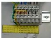
Remove the component section and the ballast units from boxes 7 and 8 by unscrewing them from the box.
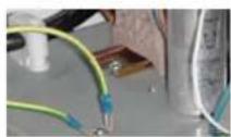
First of all connect the power cord to the component section in accordance with the sticker.
Green/yellow wire=
Blue wire = N
Fix the cord into the saddle clamp.
Connect the earth wires to the component section.

text_image
CS Doktor Sun000 "Доктор-Сан"
Now tilt the component section on its edge and position it between the leg of the stand and the side cover at the head end. Ease it flat on to the pedestal frame.
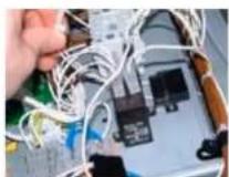
Take the cord of the display lighting and secure the connector to the component section with two tapping screws (4.8x9,5).
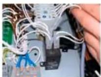
Pull the plug of wire K05 A2 from the relay.
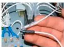
Take the loose wire beam out of box 5, take the plug of wire K05 A2 and connect the plugs with the little metal strip. Now place the joined plugs back on the relay.
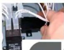
Now take the flat connector of the display lighting and plug it into the connector on the component section.
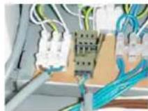
Connect the wires of the body cooler (3 pole) to the component section and secure the connector with two tapping screws (2.9x19).
Also connect the 3-pole plug of the main flow fan to the component section.
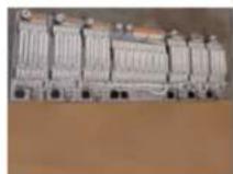
Next lay out all the ballast units in the right sequence in front of the appliance. On the left, the ballast units for the bench, then the ballast for the face tanners (for the 433: let the plug hang loose) followed by the ballast units for the canopy.
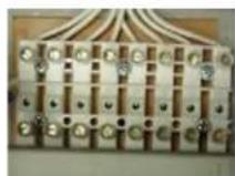
Connect all the connectors to the backs of the ballast units and secure the connectors with two tapping screws (2.9x19) per connector.
Place all the ballast units next to each other flat on the pedestal frame and connect the wire beam coming out of the component section to the black connectors on the ballast units. Make sure that no cables or wires are left lying on the ballast units.
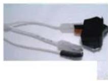
Detach the switch of the quiet-time light from the wire beam. Feed the wires with the small plugs from the inside to the outside through the side cover at the foot end. Take the loose wire of the display lighting (Xf 51-01), feed it through the side as well and connect it to the plug of wire Xf 46-01 with the little metal strip.
SUNVISION

text_image
CS Doktor SunООО "Доктор-Сан"
Now place the plugs back on the switch.
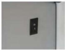
Click the switch back onto the side cover.
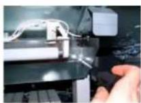
Take the fixture for the floodlight out of the box and secure it to the legs of the stand using 4 tapping screws (4.8x9,5).
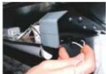
Now take the flat connector of the display lighting and plug it into the connector of the fixture for the floodlight.
Make sure that no cables or wires are left lying on the ballast units.
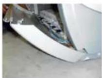
Now place the front cover of the bench into the profiles for the purpose in the pedestal frame, tilt the front cover against the underneath of the bench.
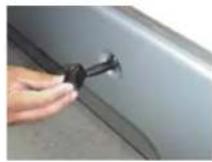
Fasten the front cover with the two locks.
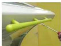
Fasten the handgrip to the front of the canopy using 3 metal screws (M5x50).
Finally remove all remaining protective film.
The power supply can now be switched on. The SunVision 400 is now ready for programming.

text_image
CS Doktor Sun000 "Доктор-Сан"
For optimal use of the SUNVISION 400 some functions can be adjusted according to your wishes. The programming is quite simple but we recommend that it be done carefully to ensure the correct functioning of the SUNVISION 400. We suggest that you make a list with your wishes before you start programming. You can change the following functions for which standard values have already been pre-programmed at the factory:
- Maximum tanning time (function 10). Standard 12 minutes, can be adjusted between 0 and 30 minutes (UV-type 4) or 0 and 60 minutes (UV-type 3).
• Face tanner adjustment facility (function 20). See step 4. - After-cooling time (function 30). Standard 4 minutes, can be adjusted between 1 12 and 5 minutes.
- Operating mode (function 40). Standard 'stand-alone'. See step 6 for options.
- Undressing time (function 50). Standard 0 minutes, can be adjusted between 0 and 4 12 minutes.
- Start position body cooler (function 61, 62 and 63) can be adjusted between position 0 and position 9.
- Time per pulse (function 70). Depends on the setting of function 40 (operating mode). Can be adjusted between 0 and 30 (or 60) minutes.
• Body tubes on/off facility (function 80). Facility available as standard.
When the appliance is plugged in, the display shows the number of the software version that is used in your SUNVISION 400. After 7 seconds it will change to '00'. When the display only shows a decimal point, the SUNVISION 400 has been programmed in the display off mode (see step 6).
◆ Programming in brief
This chapter begins with a brief explanation of programming for the more experienced programmers. In the paragraph "Programming step-by-step"

text_image
CS Doktor Sun000 "Доктор-Сан"
text_image
① ② ③ ④ ⑤ ⑥ ⑦ ⑧ start stopControl panel SUNVISION 400
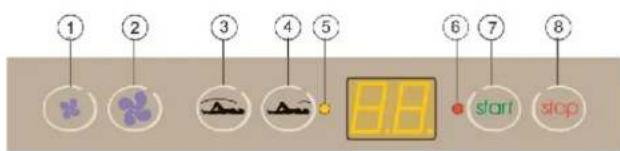
The SUNVISION 400 can be programmed with the control panel.
√ Unplug the SUNVISION 400 from its socket, plug the SUNVISION 400 back into the wall and within 10 seconds press keys (2), (3) and (4) simultaneously. You will hear a short beep. You are now in programming mode '88'. The orange LED (5) and the red LED (6) both light up.
√ 1x green key (7) takes you to the 'main mode'. The orange LED (5) is off, the red LED (6) is on, the display shows '00'.
√ Using the red key (8) you can select the functions you wish to change.
√ When in the correct function, press the green key (7) once
√ The figure shown in the display can be changed using key (3) for 'up' and key (4) for 'down'.
√ To confirm the number press the green key (7) once.
√ To exit from the 'main mode' press the green key (7) twice.
√ To save your settings press key (1) once.
◆ Programming step-by-step
In this paragraph we take you through the programming process step by step using an example.
Example: You would like a maximum tanning time of 6 minutes, no face tanner adjustment facility and 4 minutes after-cooling time. Your SUNVISION 400 will be connected to a coin box with pulse outlet, tanning time per coin is 3 minutes and 2 minutes will be allowed for undressing.
Step 1 -Activating the programming mode on the control panel
√ Unplug the SUNVISION 400 from the socket.
Plug SUNVISION 400 back into the wall. You will hear a short beep. Within 10 seconds after plugging the appliance back in, press keys (2), (3) and (4) simultaneously. The control panel display now shows '88' and the orange LED (5) and the red LED (6) both light up. You can release the keys, the control panel is now in the programming mode.
SUNVISION 400
18
05/2003
Step 2 -Selecting the main mode
√ Press the green key (7). The display shows '00, the red LED (6) stays lit while the orange LED (5) goes out. You are now in the main mode. In this mode you can select the functions you wish to change.
| Code | Function |
| 10 | Maximum tanning time |
| 20 | Face tanner adjustment facility |
| 30 | After-cooling time |
| 40 | Operating mode |
| 50 | Undressing time |
| 61/62/63 | Body cooling |
| 70 | Time per pulse |
| 80 | Body tube on/off facility |
Step 3 -Setting the maximum tanning time
This example uses a maximum tanning time of 6 minutes. The manufacturer's setting is 12 minutes.
√ Press the red key (8) once. The display shows '10'. Function 10 can now be adjusted.
√ Press the green key (7) once. The display shows a value ending with a decimal point. This value represents the setting for the number of tanning minutes. If your SUNVISION 400 has come directly from the manufacturer the figure shown will be '12.
√ Press key (4) once. The '12.'on display jumps to '11'. We have chosen 6 minutes tanning time for our example which means that key (4) must be pressed until the '11' in the display changes to '6'. Use the 'up' k (3) to increase the number of minutes.
√ Press the green key (7) once to confirm the tanning time setting. The display now shows the number '20 . Function 20 can now be adjusted.
Step 4 -Setting the face tanner adjustment facility
The 'adjustment' facility (code 01) means that the user can turn the face tanners down or off during the tanning session (manufacturer's setting). The 'no adjustment' facility (code 00) means that the user can only switch them off. The choice in our example was 'no adjustment', which means code 00. It is possible to skip the previous steps if, while in the 'main
mode', you keep pressin the display.


000 "Доктор-Сан"
√ Press the green key (7) once. The display now shows '01'.
√ Press key (4) once. The display now shows '00'
√ Confirm your selection by pressing the green key (7) once. The display now shows the number '30'. Function 30 can now be adjusted.
Step 5 -Setting the after-cooling time
In our example the choice is 4 minutes after-cooling time. If you wish to skip the previous steps, you can keep pressing the red key (8), while in 'main mode', until the number '30' appears on the display. The codes in the following table are available to set the after-cooling time:
| Code | Setting |
| 03 | 1 12 minute |
| 04 | 2 minutes |
| 05 | 2 12 minutes |
| 06 | 3 minutes |
| 07 | 3 12 minutes |
| 08 | 4 minutes |
| 09 | 4 12 minutes |
| 10 | 5 minutes |
√ Press the green key (7) once. The display now shows the code which represents the number of minutes for the after-cooling time. The
e manufacturer's setting is 4 minutes, code '08. Using key (4) this number can be reduced and using key (3) will increase the number.
√ Confirm your selection by pressing the green key (7) once. The display now shows the number '40'. Function 40 can now be adjusted.
Step 6 -Adjusting the operating mode
Our choice for this example is to use a coin box. Function 40 can now be adjusted because you have pressed the red key (8) three times while in the 'main mode' or because you have just confirmed the details in step 5 with the green key (7). The manufacturer's setting for the operating mode is 'stand-alone'. This setting corresponds with code 01. In this function you
000 "Доктор-Сан"
√ The display shows the number '40. Press the green key (7)once. The number on the display changes into '01' (manufacturer's setting).
√ Our choice was 32 (see example). Keep pressing key (3) until '32 Appears on the display.
√ Press the green key (7) once to confirm the setting. The display now shows the number '50 . Function 50 can now be adjusted.
Step 7 -Setting the undressing time
This function needs to be set only if in step 6 you opted for the coin box with pulse outlet (code 32) or the reception control system (code 16). If you wish to skip the previous steps, you can keep pressing the red key (8), while in 'main mode', until the number' 50 appears on the display. The following codes are available to set the undressing time:
| Code | Setting |
| 00 | Undressing timer not in use |
| 01 | 112 minute |
| 02 | 1 minute |
| 03 | 112 minute |
| 04 | 2 minutes |
| 05 | 212 minutes |
| 06 | 3 minutes |
| 07 | 312 minutes |
| 08 | 4 minutes |
| 09 | 412 minutes |
√ The manufacturer's setting for this function is 0 minutes. For our example we have opted for an undressing time of 2 minutes, code 04.
√ Press the green key (7) once. The display now shows '00'.
√ Press key (3) four times until the number '04' appears on the display which corresponds with an undressing time of 2 minutes (see table).
√ Press the green key (7) to confirm your selection. The display now shows '60'. Function 60 can now be adjusted.
Step 8 -Setting the body cooling start position
Your guest can decide the air volume of the body cooler, large, standard small. You can decide the strength of these three positions. There are n
text_image
① ② ③ ④ ⑤ ⑥ ⑦ ⑧ start stoppositions available, the manufacturer's setting for function 61 (small) is position '02.', for function 62 (standard) position '05.' and for function 63 (large) position '08.'. In our example we choose position '01.' for function 61. If you wish to skip the previous steps, you can keep pressing the red key (8), while in 'main mode', until the number' 60 appears on the display.
√ Press the green key (7) once. The display now shows '02'.
√ Press key (4) once to lower this number to '01'
√ Confirm this setting by pressing the green key (7). The display now shows '62'. Function 62 can be adjusted.
You can adjust function 62 (startposition '05.') following the same steps as in function 61 or go directly to function 63 by pressing the stop key (8) once.
You can adjust function 63 (large volume '08.') following the same steps as in function 61 or go directly to function 70 by pressing the stop key (8) once
Step 9 -Setting the pulse timing
Our choice for this example is the coin box with pulse outlet. The setting required for this was made in step 6. This function allows you to adjust the tanning time per pulse. The tanning time can be adjusted between 0 and 30 (or 60) minutes. We opted for 3 minutes for this example. If you wish to skip the previous steps, you can keep pressing the red key (8), while in 'main mode', until the number '70' appears on the display.

text_image
CS Doktor SunThe standard setting provides an on/off facility for the body tubes. This means that the user is able to switch the body tubes off during the tanning session. We recommend that you do not alter this setting. If you wish to skip the previous steps, you can keep pressing the red key (8), while in 'main mode', until the number '80' appears on the display.
√ Press the green key (7) once. The display now shows '01'. This is manufacturer's setting.
√ You nevertheless wish to change this setting? Press key (4) once. The display now shows '00.
√ Confirm this setting by pressing the green key (7). The display now shows '00'. You are back in the' main mode.
√ Press the green key (7) once. The red LED (6) will go out and the orange LED (5) will light up.
Step 11 -Saving all settings
Once all the settings have been introduced they need to be stored in the active database of your SUNVISION 400. Please make sure that this is done correctly to ensure that your settings are stored. Keep pressing the red key (8) until '00' appears on the display (the 'main mode') or from function 80 use the green key (7).
√ Press the green key (7) once. The orange LED (5) and the red LED (6) will both light up as an indication that you are leaving the programming mode.
√ Press key (1) once to save the settings. If this has been successful you will hear a short beep.
All adjustments have now been made and your SUNVISION 400 has now been programmed according to your wishes. All your settings have been stored and will remain in the memory even in the event of a power failure.


000 "Доктор-Сан"
Once the user is reclining on the SUNVISION 400, the canopy is lowered. The control panel will be visible above the face tanners in front of the user.
The material and printing of the control panel are selected so that the user can read the text and symbols optimally during tanning, i.e. through UV goggles. The control panel is covered by a membrane, making dirty edges a thing of the past and cleaning easy.
◆ Description of the control panel
On the control panel the following can be seen from left to right:
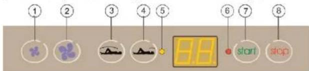
text_image
① ② ③ ④ ⑤ ⑥ ⑦ ⑧ start stop1 - key for cooling decrease
2 - key for cooling increase
3 - key for body tubes on / off
4 - key for face tanners on / off
5 - orange LED
6 - red LED
7-green key 'start'
8 - red key 'stop'
How to use the control panel
Body cooler increased (2) / reduced (1)
A body cooler has been placed at the foot of the bench of the SUNVISION 400. The degree of body cooling can be adjusted in increments via the control panel.
Pressing the key with the large ventilator symbol (2), makes the body cooler blow harder. Pressing the key with the small ventilator symbol (1) reduces the body cooling effect.
While the ventilator keys are being pressed the level of the cooling effect can be seen on the display. There are three levels:


ООО "Доктор-Сан"
Once the level of the body cooling has been adjusted, the level remains visible for about 1 second on the display.
BODY TUBES ON / OFF (3)
By pressing the key for the body tubes (3) all the body tubes in the bench and canopy are switched off. By pressing the key again the body tubes come back on. If the body tubes do not respond to this key, the '00' setting was selected during the programming making the on/off facility for the body tubes unavailable.
Face tanners on / off (4) (not applicable for SunVision 433)
By pressing the key for the face tanners (4) the face tanners are switched on or off. If the user keeps the key for the face tanners (4) pressed down for longer than 1 second, the face tanners will switch off. The orange LED (5) goes out when face tanners are switched off. Pressing the key once again will restart the face tanners.
WARNING: switching the face tanners on and off in quick succession may damage the tubes. A warm lamp is more difficult to start up.
Adjusting the strength of the face tanners. (not applicable for SunVision 433)
Depending on the programmed settings (see chapter 'PROGRAMMING'), this key can also allow the user to adjust the strength of the face tanners. This is only possible if the '01' setting was selected during the programming as this activates the face tanner adjustment facility
If the key for the face tanners (4) is pressed for less than 1 second the face tanners will switch from high power to normal power. In the case of the SUNVISION 444 the capacity is reduced from 320W to 240W. In case of the SUNVISION 466 the capacity is reduced from 400W to 300W. In the case of the SUNVISION 422 only 8 of the 16 PL-L tubes will remain on. The orange LED (5) will start flickering. Another brief touch (less than 1 second) on the key for the face tanners (4) will switch the face tanners back to high power. The orange LED (5) will stop flickering and will now glow continuously.
Display
The display shows the tanning time in minutes, rounded up. The last minute is shown in seconds.
SUNVISION 400
RED 'STOP' KEY (8)
Stop key (8) allows the user to put the SUNVISION 400 into pause mode. The body tubes and the face tanners will switch off. The remaining tanning time on the display continues to 0. The pause mode will last for 30 seconds.
If the user presses the start key (7) within 30 seconds, the pause mode is cancelled and the tanning time will continue from the point before the pause. This makes it possible for the user to continue the tanning session after accidentally pressing the stop key (8).
If the start key (7) is not pressed again within the 30 seconds pause, the SUNVISION 400 switches off. The ventilators will continue to provide after-cooling so that the SUNVISION 400 is ready quickly for the next user. The red LED (6) on the display glows to show that the after-cooling process is active.
GREEN 'START' KEY (7)
If your SUNVISION
( ' 0 1 ) , the following operating instructions sh
√ The user presses the start key (7). The display now shows the tanning time in minutes and the orange LED (5) has lit up.
√ Each press of the start key (7) will reduce this time by 1 minute. This can be continued until the desired tanning time has been reached. The tanning time cannot be increased.
If your SUNVISION 400 has been programmed in the 'reception control mode (16)', the SUNVISION 400 can be started in two different ways:
- When start is pressed in the reception SUNVISION 400 gives three beeps. The beeps indicate that the undressing time has begun. The number of tanning minutes is shown on the reception display. The undressing time (if set) counts down to 0 on the display of the SUNVISION 400. The user undresses, lies down on the SUNVISION 400 and presses the start key (7). This interrupts the remaining undressing time and the SUNVISION 400 comes on straightaway. When the undressing time has passed the SUNVISION 400 comes on, regardless of whether the user is in it or not.
At that point the tanning time can be seen counting down in minutes (the last minute is shown in seconds) on the reception display. If start is pressed repeatedly at the reception or at the sunbed, the tanning time is decreased in steps of 1 minute. If stop is pressed at the
05/2003
reception, the SUNVISION 400 stops.
- If the sunbed has not been started by the reception, the user can indicate this by pressing the start key (7). Three beeps will be heard at the reception. The displays of the SUNVISION 400 and the reception control will flash with the set tanning time. The reception can switch the SUNVISION 400 on by pressing start and, if necessary, can then decrease the tanning time in one-minute steps by holding down the start key. It is not possible to increase the tanning time.
If stop is pressed at the reception during tanning, the SUNVISION 400 will switch off. If, during tanning, the stop key (8) is pressed on the control panel of the SUNVISION 400, it switches over to pause mode for 30 seconds. If the start key (7) is pressed within 30 seconds, the SUNVISION 400 will continue. When the 30 seconds have passed the SUNVISION 400 will stop and switch over to after-cooling.
If your SUNVISION 400 has been programmed in the 'coin box with display on mode'(code 02) or in the 'coin box with display off mode' (code 04) the following operating instructions should be followed.
The user inserts a number of coins into a coin box and the SUNVISION 400 will start up. '00' appears on the display (only with code 02) and the tanning time will increase during the session to the value of the coins inserted. The coin box switches the SUNVISION 400 off when the tanning time has passed.
If the stop key (8) on the control panel is pressed during tanning the SUNVISION 400 will switch over to pause mode for 30 seconds. If the start key (7) is pressed within 30 seconds, the SUNVISION 400 will continue. After the 30 seconds, the SUNVISION 400 will stop and switch over to after-cooling.
If your SUNVISION
pulse outlet mode'(code 32) the following operating instructions should be followed.
The user inserts a number of coins into the coin box and the display on the reception control system will start to flash. Each time a coin is inserted a beep will be heard. Coins can be inserted until the maximum tanning time has been reached. If coins are inserted after the maximum tanning time has been reached, three beeps will be heard each time.
15 seconds after the last coin has been inserted the undressing time will start. On the display of the SUNVISION 400 the undressing time is counted down and the start key can be pressed. After the undressing time has finished or the start key has been pressed, the SUNVISION 400 will start. Inserting coins during tanning has no effect. If the stop key is pressed on the SUNVISION 400 control panel during tanning the SUNVISION 400 will switch over to pause mode. If the start key is pressed within those 30 seconds the SUNVISION 400 will continue. After the 30 seconds have passed the SUNVISION 400 will stop and switch over to after-cooling.
Quiet-time lighting
The SUNVISION400 has one lighting tube that provides light for the appliance while not in active use. It also has an illuminated display in the canopy and a floodlight in the bench. These illumination elements can be switched on and off with the aid of a switch which is located at the foot end next to the body cooler.
When the quiet-time light is switched on, the tube in the canopy which is closest to the handle should burn. If this is not the case, the connectors at the backside of the ballast units (the three units at the right side of the machine) should be changed until the right tube is burning. Screw the connectors back on the ballast units using the parkers after changing them.


ООО "Доктор-Сан"
As the owner or employee of a tanning studio you naturally know how to use your tanning equipment. Nevertheless, we will now list the 'regulations' and recommendations once again. This should enable you to offer your guest good advice about healthy, safe and hygienic tanning using the SUNVISION 400.
Benefits
The use of tanning equipment has a number of beneficial effects on our health. Apart from a 'healthy' colour, sunlight promotes the generation of vitamin D3, which is important for our entire bone system. Sunbathing thus has a beneficial effect in the treatment of osteoporosis. Many people experience an alleviation of muscular pain and rheumatic complaints after a tanning course. There are also indications that sunbathing has a beneficial effect upon metabolism, blood pressure and cholesterol levels. But by far the greatest effect of sunshine appears to be its effect on our mood. We become happier and more energetic and it is a great way of combating stress and fatigue.
Skin types
White skinned people can be divided into four skin types: I to IV inclusive. Skin type I contains no pigmentation and cannot tan at all, can tan very little, when exposed to the sun. People with this skin type are most likely to suffer from sunburn and should not use any tanning equipment without seeking advice from a doctor first. Skin type IV is a tinted, light skin, the epidermis of which naturally contains a pigment, which can easily be further developed by sunbathing without the danger of sunburn. Skin types II and III represent the transition from I to IV.
It is important that your guest is aware of the sensitivity of his or her skin and skin type before using tanning equipment. Your guest's experience with natural sun is an important guideline here. The list of questions can help your guest to reach a reasonable approximation of his or her skin type.

text_image
CS Doktor SunООО "Доктор-Сан"
How sensitive is the skin?
Answer the questions and write down the figure in question:
What colour are the eyes?
Light blue/green/grey....0 Blue/grey/green....2
Light brown....4 Dark brown/black....8
What is the natural hair colour?
Red/blonde/brown 0 Mid-brown 2
Dark brown/black. 4
What colour is the untanned skin?
Reddish 0 White but not pallid 2
White to beige....4 White to brown....8
Light brown/olive coloured....16 Dark brown....20
Has your guest got many freckles?
Yes 0 No 4
How does the skin react after having been out in the sun for a few hours at the beginning of summer?
Painfully burnt, pealing
..0 Burnt/peeling slightly .....2
Somewhat burnt
..4 Very slightly burnt....8
Not burnt....'12
How brown is your guest after a week's holiday with lots of sun?
Not brown or hardly brown .....0 Somewhat brown.....2
Deep brown .....4 Skin is naturally brown .....8
Check the figures and add up the total. You can determine your guest s
skin type using the table below.
Skin Sensitivity table Definition
| <12 | I | Very sensitive skin |
| 12-18 | II | Sensitive skin |
| 19-25 | III | Normal skin |
| 26-40 | IV | Skin with very good resistance to the sun |
| >40 | V of VI | Naturally brown skin |
SUNVISION 400

text_image
CS Doktor Sun000 "Доктор-Сан"
A course plan consists of eleven days (or thirteen days, depending upon the skin type), the second day of which is a rest day. There is a rest period of 48 hours between the first and second tanning sessions, and a rest period of 24 hours between all subsequent tanning sessions. The tanning time on the first day is never less than 3 minutes. Recommend your guests not to use tanning equipment more often than 50 times per year. Also recommend to observe a rest period of 4 weeks between each sunbathing course.
In table 2 you can find the tanning time for your guest, which will depend upon the skin type of your guest and the type of tubes in your SUNVISION 400.
IMPORTANT: The tanning times given (in minutes) in table 2 are based upon the standard version of the SUNVISION 400. Different tube combinations require different tanning times. Tables for other tube combinations are available from your distributor upon request.
SUNVISION 422 XXL Bench: SUNVISION XTR 200 Plus 120W UV-type 4 Canopy: Brilliant Sun R-Intensive 100W
| sunbath | skin type II | skin type III | skin type IV |
| 1 4 4 4 | |||
| 2 4 5 5 | |||
| 3 5 6 6 | |||
| 4 5 6 7 | |||
| 5 6 7 9 | |||
| 6 6 8 | 10 | ||
| 7 7 9 | 11 | ||
| 8 | 7 | 10 12 | |
| 9 | 8 | 11 13 | |
| 10 | 8 | 12 15 | |
| 11 | 9 | 12 16 | |
| 12 10 13 17 | |||
TABLE 2
SUNVISION 422 XXL Bench: SUNVISION XTR 200 Plus 120W
UV-type 3 Canopy: Brilliant Sun plus R-XT 100W
| sunbath | skin type II | skin type III | skin type IV |
| 1 6 6 6 | |||
| 2 6 7 7 | |||
| 3 7 8 9 | |||
| 4 | 8 | 10 11 | |
| 5 | 9 | 11 13 | |
| 6 | 10 12 15 | ||
| 7 | 10 13 16 | ||
| 8 | 11 15 18 | ||
| 9 | 12 16 20 | ||
| 10 13 17 22 | |||
| 11 13 19 24 | |||
| 12 14 20 26 |
SUNVISION 433 XXL Bench: SUNVISION XTR 200 Plus 120W UV-type 4 Canopy: SUNVISION XTR 200 DuoTan 1
| sunbath | skin type II | skin type III | skin type IV |
| 1 4 4 4 | |||
| 2 4 4 5 | |||
| 3 5 5 6 | |||
| 4 5 6 7 | |||
| 5 5 7 8 | |||
| 6 6 8 9 | |||
| 7 6 8 | 10 | ||
| 8 7 9 | 11 | ||
| 9 | 7 | 10 13 | |
| 10 | 8 | 11 14 | |
| 11 | 8 | 12 15 | |
| 12 | 9 | 12 16 |
SUNVISION 444 XXL Bench: SUNVISION XTR 200 Plus 120W UV-type 3 Canopy: Brilliant Sun plus R-XT 100W
| sunbath | skin type II | skin type III | skin type IV |
| 1 6 6 6 | |||
| 2 7 7 8 | |||
| 3 8 9 | 10 | ||
| 4 | 8 | 10 12 | |
| 5 | 9 | 11 13 | |
| 6 | 10 13 15 | ||
| 7 | 11 14 17 | ||
| 8 | 12 15 19 | ||
| 9 | 12 17 21 | ||
| 10 13 18 23 | |||
| 11 14 19 25 | |||
| 12 15 21 27 |
SUNVISION 444 XXL Bench: SUNVISION XTR 200 Plus 120W UV-type 4 Canopy: Brilliant Sun R-Intensive 100W
| sunbath | skin type II | skin type III | skin type IV |
| 1 4 4 4 | |||
| 2 4 5 5 | |||
| 3 5 6 6 | |||
| 4 5 6 7 | |||
| 5 6 7 9 | |||
| 6 6 8 | 10 | ||
| 7 7 9 | 11 | ||
| 8 | 7 | 10 12 | |
| 9 | 8 | 11 13 | |
| 10 | 8 | 12 15 | |
| 11 | 9 | 12 16 | |
| 12 10 13 17 | |||


IMPORTANT: Bear in mind that new lamps in the first 50 hours of use emit around 20% more 'UV output'. During this period you should reduce the tanning time by around 20%.
Sensible tanning
Tanning with tanning equipment is not without risks. Careless and excessive use of tanning equipment, like excessive exposure to the sun, increases the probability of eye and skin disorders. The degree to which these effects occur is partially determined by the intensity and duration of sunbathing, but is also influenced by the sensitivity of the person in question.
Various European countries have guidelines and recommendations to reduce or prevent the risks associated with sunlight. It is in your own interest and that of your guest to follow your country's guidelines for tanning.
The safe annual dose of sunlight was found to be 15 Kj/m² by CEI/ICE (reference number: 335-2-27:1995).
Your guest would do well to strictly observe the instructions in this manual before beginning tanning.
√ Care should be taken in determining your guest's skin type before tanning and you should ensure that the tanning plan based upon this skin type is followed.
√ Children under 16 years of age and people with skin type I are advised not to sunbathe, i.e. not even outside. The only possible use of tanning equipment for people with skin type I is for 'light therapy' in consultation with a doctor.
√ We recommend that cosmetics are removed several hours before tanning. Some substances can influence the skirf's sensitivity to light. Sun cosmetics with a protection factor may not be used during tanning. Special cosmetic products for sunbathing can, of course, be used.
√ Recommend your guests not to wear jewellery during tanning.
√ Bathing or showering before tanning is not recommended, because soap dissolves the natural oils of the skin. Furthermore, the same precautions apply for the SUNVISION 400 as those for any other electrical equipment: Do not use in the direct vicinity of water or with wet skin.
√ Just as for natural sunbathing it is a good idea to look after the skin using a moisturiser and nourishing cream after tanning (and showering).
√ UV light is harmful to the naked eye. Never look into the tubes when they are on. Unprotected eyes can become infected due to sunbathing and in certain circumstances - for example in the event of excessive exposure - sunbathing can lead to damage to the retina. Excessively frequent exposure can lead to cataracts over time. Ensure that your guest protects his or her eyes with sunglasses that are suitable for this purpose (UV goggles).
√ Contact lens users are advised to remove their lenses.
√ Excessive exposure to UV light from the sun or from tanning equipment can lead to a burnt skin. Sunbathing too often can lead to a rapid ageing of the skin and an increased probability of skin complaints.
√ Draw your guest's attention to the fact that the skin may not be exposed to UV light more frequently than once per day.
√ Ask your guest to be patient. Tanning is not like painting where the final coat 'covers' immediately. Try not to force the pace.
√ Some medicines contain light-sensitive substances that can influence the skin's sensitivity to UV light. Advise your guests to carefully read the instructions accompanying a medicine and to consult a doctor in case of any doubt.
√ If the skin unexpectedly goes red during tanning, there is probably a heat erythema due to blood vessel dilatation. This causes excessive heat to be carried away more quickly. Allow the body to cool, reduce tanning times and try to prevent perspiration.
√ Refer your guest to a doctor if he or she suffers skin problems.
√ Some women react differently to UV light when pregnant than normal. Look out for this well and avoid UV light in the event of excessive sensitivity. UV light is not dangerous to an unborn child.
√ Sunbathing with varicose veins is not a problem, provided the feet are raised slightly, for example by resting them on a rolled up cloth.
√ Pacemakers are tested comprehensively by the manufacturer and are resistant to normal UV light.
◆ Further information
Alisun Europe B.V. publishes a handy booklet in which the most frequently asked questions about sunbathing using tanning equipment and in natural sunlight are answered. The booklet is entitled 'The sundial by Alisun' and is available from your distributor.

text_image
CS Doktor Sun000 "Доктор-Сан"
IMPORTANT: Always disconnect the power supply from the SUNVISION 400 before performing maintenance or servicing.
Cleaning
Clean the bench acrylic sheet after each use with an appropriate, non-abrasive cleaning agent. Also clean the canopy acrylic sheet regularly. Choose a cleaning agent that does not contain ammonia or alcohol. These substances will cause hairline cracks in the acrylic sheet. Wipe the acrylic sheets with tissue or a soft, clean cloth
For optimal results, and to guarantee a long and trouble-free lifetime, we recommend that you clean the sunbed regularly, according to the following procedure:
Clean both sides of the acrylic sheets. Further down in this chapter we describe how you can remove the acrylic sheets from the SUNVISION 400.
Turn the tubes through 90° and remove them from the tube holders. Clean the entire length of the tubes with a damp cloth. (Before you can remove the body tubes of the SUN VISION 422 you first need to remove the PL-L tubes).
Use a vacuum cleaner to clean dirty areas in the SUNVISION 400.
Twist the clean tubes in the tube holders. To replace the tubes push the contact pegs of the tube as far into the tube bases as possible, then turn the tube through 90°.
ATTENTION:
√ Avoid touching the tube with your fingers. Fingerprints will burn into the surface of the glass.
√ Reflector tubes should be placed so that the label is visible at the bottom-end of the SUNVISION 400.
Replace the acrylic sheets and check that they are secured.
◆ Removal of the acrylic sheets
Comment:
√ Only remove acrylic sheets from the sunbed when the SUNVISION 400 is at room temperature.
SUNVISION 400


ООО "Доктор-Сан"
Perform the following operations to remove the acrylic sheets:
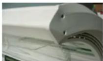
√ Insert a flat-bladed screwdriver with a minimum blade size of 6 mm on the top between the plastic profile and the acrylic sheet.
√ Turn the screwdriver and carefully lift the plastic profile. The plastic profile will now come free from the aluminium profile.
√ Perform the same operations on the other side of the acrylic sheet.
√ Pull the plastic profile completely free from the acrylic sheet on both sides.
√ The acrylic sheet can now be pushed sideways out of the bench or canopy.

◆ Fitting the acrylic sheet
Perform the following operations to fit the acrylic sheets in the bench or canopy:
√ Push the acrylic sheet sideways back into the bench or canopy.
√ Click the plastic profiles back into place.
Tubes
The tubes fitted to the canopy of the SUNVISION 466 provide an average of 800 effective operating hours. The tubes in the bench and the tubes in the canopy of the SUNVISION 422, SUNVISION 433 and SUNVISION 444 give an effective lifetime of 500 hours. The tubes may function for longer but the 'UV output' is reduced to the degree that tanning is noticeably reduced after this period.
If you are not sure whether the tubes have sufficient 'UV output you can have the tubes measured and replaced if necessary. Contact your distributor.
IMPORTANT: Bear in mind that new tubes in the first 50 hours of use emit around 20% more 'UV output'. During this period the tanning time should be reduced by 20%.
Only replace tubes with tubes of the same type. A different type of tube will also have a different UV output, which will alter the tanning time.
PL-L tubes (SUNVISION 422)
Perform the following operations to replace the PL-L tubes:
√ Disconnect the power supply from the SUNVISION 422.
√ Remove the acrylic sheet from the canopy.
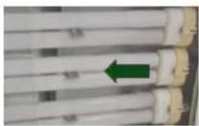
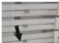
√ Slide the PL-L tube in the direction indicated by arrow, thereby releasing the tube from the socket.
√ Now pull the tube slightly towards you, thereby releasing the tube from the holder.
√ Place the new PL-L tube.
√ Place the acrylic sheet back into place.
◆ High-pressure face tanners (SUNVISION 444, 466)
Perform the following operations to replace the high-pressure tubes:
√ Disconnect the power supply from the SUNVISION 444/466.
√ Remove the acrylic sheet from the canopy.
√ Support the filter glasses with your hand and use the 4mm hex key to loosen the socket-head screw by turning it counterclockwise 90 degrees.
√ Slide the glass holder to the right until it is released from the brackets on the left-side.
√ You can now remove the glass holder with the filter glasses from the casing and exchange the tube.
ATTENTION:
√ Avoid touching the tube with your fingers. Fingerprints will burn into the surface of the glass, causing the tube to shatter after a short time. Position the new tube using a clean cloth or piece of paper. If you have touched the glass by accident, you can remove the fingerprints with a clean cloth.
√ The tube holders are equipped with sprung contacts, which enables the new
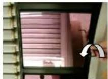
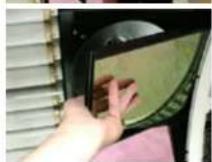
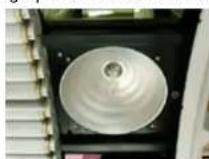
tube to be fitted easily.
√ Place the glass holder with the filter glasses back into the casing and see to it that the clear glass is once again positioned on the inside (tube side).
√ Slide the glass holder back into its original position and secure it with the socket-head screw by turning it clockwise 90 degrees.
High-pressure tubes have a very high intensity in the UV-B range and even in the dangerous UV-C spectrum. If UV-C radiation reaches the skin, the skin will burn immediately. It is therefore absolutely imperative to avoid direct radiation from high-pressure tubes.
IMPORTANT: If a filter glass of a face tanner is broken, the SUNVISION 400 may not be used under any circumstances.
High-pressure tubes contain heavy metals that sometimes precipitate onto the inside of the glass tube. This is a normal effect and the metal globules will vaporise as soon as the tube reaches its operating temperature.
Service
All electrical components are housed inside the bench. By opening the two locks the entire front panel of the SUNVISION 400 can be removed all at once, which creates generous access for servicing. The electrical components are all within easy reach and where necessary can be lifted out of the sunbed for servicing and maintenance. All ballast units and other parts are of an easily manageable size.
If replacement components are required, e.g. ballast units, reflectors, a control panel, etc. it is important to use only original parts. If this is not done the UV capacity may be affected. The replacement of parts should ideally be carried out by a qualified service technician. For further information we recommend that you contact your distributor.

Step 1 -Activating the programming mode on the control panel
√ Unplug the SUNVISION 400 from its socket. √ Plug the SUNVISION 400 back into the wall.
√ You will hear a short beep. Within 10 seconds after putting the plug back in the socket press keys (2), (3) and (4) simultaneously. The control panel display will show '88' and the orange LED (5) and the red LED (6) both light up. The keys can now be released, the control panel is now in programming mode.
Step 2 -Selecting the main mode
√ Press the start key (7). The display shows '00, the red LED (6) remains lit while the orange LED (5) goes out. You are now in the main mode.
Step 3 -Selecting the service mode
√ Press the start key (7) once more. The red LED (6) goes out and the orange LED (5) lights up. You are now in the service mode.
Step 4 -The different functions
√ While in the service mode you can use the red key (8) to browse through the 9 different functions. The functions are:
| Code | Function |
| 10 | Number of times body tubes switched on |
| 20 | Number of body tube operating hours |
| 30 | Number of times face tanners switched on |
| 40 | Number of face tanner operating hours |
| 50 | - Not in use - |
| 60 | - Not in use - |
| 70 | Cumulative number of users |
| 80 | Cumulative number of operating hours |
| 90 | 'Resetting' the counters |
SUNVISION 400
Step 5 -Reading the information
√ The function you wish to read can be selected by pressing the green (start) key (7).
Please note: The red key (8) allows you to browse through the functions while the green key (7) allows a specific one to be selected.
√ As soon as the green key (7) has been pressed, two numbers light up on the display. The value on the left indicates the number of digits that make up the value of the selected function. The dot at the right bottom corner indicates that the display is showing a value
√ Note the value indicated on the right and continue pressing (3). Note each successive number on the right-hand of the display until the number on the left-hand side of the display has reached 1. The number last displayed on the right-hand side is the last digit of the total figure or value for the function you have selected.
Example: reading the number of body tube operating hours:
√ Select function 20.
√ The display shows [40.] This is the first number, note 0.
√ Press key (3). The display shows [32.], note 2 (02).
√ Press key (3) again. The display shows [29.], note 9 (029)
√ Press key (3) once more. The display shows [13.] (the number 1 on the left-hand side of the display indicates that the last digit of the total number is being shown), note 3 (0293).
√ This means that the number of body tube operating hours is 293.
Step 6 -Returning to the service mode
√ Press key (3) again. You are now back in the service mode. The next function is now available for reading or, using key (8), different functions can be found.
Step 7 - Resetting the counters
√ Function 90 allows you to reset all values (return to 0 setting). Only the following values can be reset:

√ Using the red key (8) browse through to function 90 (resetting the counters) and press the green key (7) once to select function 90.
√ The display now shows '10.' The dot at the right-hand bottom corner indicates that this function can now be reset. You can now:
a. reset the function shown on the display (function 10) using the red key (8), or
b. use key (3) to browse to the desired function, which can then be reset using the red key (8).
√ Function 90 can be left by pressing key (3).
Example: resetting the body tube operating hours:
√ Select function 20.
√ The display shows [20.] Press the red key (8) to reset the body tune operating hours.
√ Select function 20. √ The display shows [20.] Press the red key (8) to reset the body tune operating hours.
Step 8 -Leaving the service mode
√ You can leave the service mode by pressing the green key (7) just once. The orange LED (5) and the red LED (6) will both light up. Now press key (1) to leave the service mode. You will hear a short beep in confirmation.


000 "Доктор-Сан"
COINBOX AND RECEPTION CONTROL SYSTEM
A coinbox -connected to the control print of the S UNVISION 400 -controls the software of the sunbed. A separate power supply must be provided for the coinbox.
An Alisun reception control system does draw its power supply from the SUNVISION 400. The correct functioning of the coinbox in combination with the SUNVISION sunbeds requires a potential free (= voltage free) contact with the coinbox. Alisun has developed a coinbox interface (art.nr.: 355170) so that coinboxes that have no potential free contact can be used. For more information please contact your distributor.
If a reception control system or coinbox is installed, you select the required operating mode during programming. There are five options for the operating mode:
01 = stand alone (the manufacturer's setting)
02 = coinbox - with S UNVISION 400 display on
04 = coinbox -with S UNVISION 400 display off
16 = reception control system
32 = coinbox -with pulse outlet
- 'PROGRAMMING' chapter describes the programming of the SUNVISION 400 for these options. Operation is described in the chapter entitled 'OPERATION'.
Connecting the reception control system
IMPORTANT: Always disconnect the power from the SUNVISION 400 before performing maintenance or servicing on the sunbed.
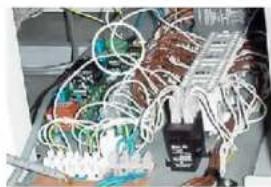
If you remove the front of the bench, you will see the component section with the connections for the coinbox and the reception control system at your right-hand side.
In the picture below the connection for the reception control sytem has been numbered from the top down 1,2,3 and 4.
natural_image
Electrical wiring harnesses and connectors in a room (no visible text or symbols)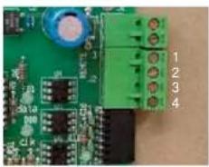
natural_image
Close-up of a green printed circuit board with visible components and connectors (no readable text or symbols)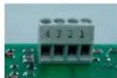
In the box for the reception control system you will see 4 poles numbered from left to right 4, 3, 2 and 1.
Connect the cables so that number 1 on the reception control system is connected to number 1 on the printed circuit board. Similarly, connect the
other terminals with the corresponding number, i.e. 2 with 2, 3 with 3 and 4 with 4.
Connecting the coinbox
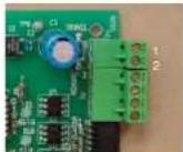
On the printed circuit board of the UNSISION 400 the numbers 1 and 2 have been reserved for the connection of a coinbox.

Connect the cables to the poles of the potential free contact in the coinbox.


000 "Доктор-Сан"
- The SUNVISION 400 'does nothing'
√ Check whether the SUNVISION 400 is plugged in.
√ Check whether the SUNVISION 400 is correctly programmed. See the chapter 'PROGRAMMING'.
√ Check the mains supply; if necessary replace the group fuse.
√ Check whether the fuse in the SUNVISION 400 is defective.
- The SUNVISION 400 still does not work
√ The SUNVISION 400 may be connected to a group to which several items of equipment are already connected. If in any doubt contact your distributor or the electricity company.
√ The control panel needs replacing. Contact your distributor.
- One tube does not come on
√ Replace the tube that does not work with one that does.
√ If this tube does not work, replace the starter.
√ If this tube does work, replace the previous tube.
√ If the tube still does not work, it is likely that the ballast has to be replaced. Contact your distributor.
- The tubes flash on and off
√ The voltage is too low. Consult your electricity company.
√ The environmental temperature is too low. Warm the environment (temporarily).
- The SUNVISION 400 gets too hot
√ Check whether the ventilators turn (and check if they turn in the right direction) when the SUNVISION 400 is switched on. Contact your distributor if this is not the case.
√ Check whether the air exhaust system is correctly connected. See the chapter 'PREPARATION'.
√ The environmental temperature is too high. Ventilate the area.
- The canopy does not remain stationary in any given position.
√ See the chapter 'ASSEMBLY'. Check whether the gas absorbers have been correctly assembled. Change the postions if necessary.
√ If this has no effect, (one of) the gas absorbers might be defective. Contact your distributor.
SUNVISION 400
32
05/2003
◆ Possible fault signals and solutions
In normal condition with the unit in standby mode the display should show 00 and on the mainprint LED D1 is on and LED D10 and LED D11 are flashing.
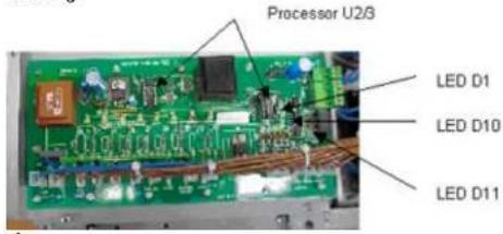
text_image
Processor U2/3 LED D1 LED D10 LED D11In the scheme below can you see the possible fault signals and solutions.
| Fault | Cause | Solution |
| F1 in display. On mainprint LED D11 out. | Fault signal on sticking relays or loose (sense or output) wire. | Check relays for sticking or loose wires. Reset by power off and on. |
| F1 in display. On mainprint LED D11 out. | Overruletimer. | Reset by power off and on. |
| F1 in display. On mainprint LED D1, D10 and D11 on | Connection between foil and print | Take the connector out and put it in again. |
| Control unit beeping with right point in display. | Coin box hanging. Check coin contact, reset by closing the coinbox contact. | |
| Sunbed goes in after-cooling forever. Display _0 . On mainprint LED D10 flashing and D1 and D10 out. | Cable control unit not properly connected. | Check cable and connectors. |
| Sunbed goes in after-cooling forever. Display _0 . On mainprint LED D1 on and D10 and D11 out. | Cable control unit not properly connected. | Check cable and connectors. |
| Sunbed goes in after-cooling forever. Display out. On mainprint LED D11 flashing and D1 and D10 out. | Cable control unit not properly connected. | Check cable and connectors. |
| Sunbed goes in after-cooling forever. Display out. LED D1, D10 and D11 out. | Cable control unit not properly connected. | Check cable and connectors. |
PARTS LIST
The following parts for the SUNVISION 400-series can be ordered from your distributor:
| Description | ART. NR. |
| Blue filter glass TrueTan Power Focus (235x235mm) | 345905 |
| Heat resistant glass 235x235mm Soladur | 345916 |
| High-pressure tube Ariana N 300/500 SE | 350808 |
| PL-L tube 55W | 350720 |
| SUNVISION XTR 200 Plus 120W | 350456 |
| SUNVISION XTR 200s 120W | 350446 |
| Brilliant Sun plus R-XT 100W | 350376 |
| Brilliant Sun Intensive 100W | 350306 |
| Brilliant Sun R Intensive 100W | 350316 |
| Cosmolux VHR4 160W | 350190 |
| Cosmolux RCS 100W | 350159 |
| SUNVISION XTR 200 DuoTan 180W | 350681 |
| Tube holder plate SUNVISION 444/466-canopy, head-end 341370 | |
| Tube holder plate SUNVISION 444/466-canopy, foot-end 341371 | |
| Tube holder plate SUNVISION 422-canopy, head-end 341372 | |
| Tube holder plate SUNVISION 422-canopy, foot-end | 341373 |
| Tube holder plate SUNVISION 422/444/466-bench | 341374 |
| Tube holder plate PL-L tubes 422-canopy | 341375 |
| Reflector 1-tube FT SUNVISION 444/466, parabolic 332862 | |
| Control PCB SV400 | 356513 |
| Control panel SV400 with cable | 356586 |


000 "Доктор-Сан"
Some cleaning products are not suitable for cleaning your sunbed. For example: Cleaning agents containing ammonia or alcohol will attack the surface of your sunbed, which will accelerate the ageing process.
Other cleaning products may react with the UV light from the sunbed. We recommend that you make sure you are well informed about the products that you use for cleaning your sunbed.
Old UV tubes are chemical waste and should be handed in at institutions that treat chemical waste according to the laws of your country.
If you wish to replace any tanning equipment please contact your distributor for the correct disposal procedure.
DECLARATION OF CONFORMITY
In accordance with ISO/IEC guide 22 and EN 45014
Name of manufacturer:
Mercuria Beheer B.V.
Address of manufacturer:
Celsiusstraat 33
1704 RX HEERHUGOWAARD NEDERLAND
declares that his product:
All SUNVISION tanning equipment
complies with the requirements of the European Low Voltage Guideline 72/23/EEC and 93/68/EEC and the EMC guideline 89/336/EEC and bears the appropriate CE mark.
GUARANTEE CONDITIONS
- The guarantee period begins on the date of purchase and ends 12 months after this date. The guarantee is non-transferrable and is therefore only valid for the first purchaser.
- Work under the guarantee will only be carried out upon presentation of the invoice for the SUNVISION 400.
- Components that are subject to the normal wear process such as tubes, starters and acrylic sheets, are not covered by the guarantee.
- The guarantee is invalidated if modifications are made to the SUNVISION 400 without the express written permission of the manufacturer. This is true regardless of whether these modifications can be shown to be directly associated with the defect.
- Malfunctions that are the result of installation errors and/or incorrect usage are not covered by the guarantee. We therefore strongly recommend that you read carefully and follow the regulations regarding assembly, installation and use.
- When reporting a fault under guarantee you should quote the serial number and the model.
- The guarantee only covers the replacement of defective components. Normal wear excepted. Travelling and labour costs are not covered by the guarantee.


ООО "Доктор-Сан"