X10 (2016) - Boat MASTERCRAFT - Free user manual and instructions
Find the device manual for free X10 (2016) MASTERCRAFT in PDF.


User questions about X10 (2016) MASTERCRAFT
0 question about this device. Answer the ones you know or ask your own.
Ask a new question about this device
Download the instructions for your Boat in PDF format for free! Find your manual X10 (2016) - MASTERCRAFT and take your electronic device back in hand. On this page are published all the documents necessary for the use of your device. X10 (2016) by MASTERCRAFT.
USER MANUAL X10 (2016) MASTERCRAFT
2016 BOAT OWNER'S MANUAL
CONGRATULATIONS
On your boating choice! MasterCraft is the recognized world leader for inboard boats today and has been for over forty-five years. The quality, innovation, selection and value of MasterCraft boats are unmatched in the industry.
Please take a few minutes to read this Owner's Manual completely, in addition to carefully reviewing any additional information provided in the accompanying packet. These publications will help to answer most of the remaining questions you may have regarding the new boat. If you have any additional questions after reading these publications, please feel free to speak with your dealer. MasterCraft wants you to feel comfortable with your boat (and trailer, where applicable) from the very beginning of your experience as an owner of our products.
All information in this Owner's Manual is based on the latest product information available at the time of printing. Because of our policy of continuous product improvement, we reserve the right to make changes at any time, without notice, in specifications and models, and also to discontinue models. We also reserve the right to change specifications, parts or accessories at any time without incurring any obligation to equip the same on models manufactured before the date of the change. MasterCraft recommends checking www.mastercraft.com periodically, specifically the Knowledge Center, for updates and additional information.
Due to changes in specifications, models, parts and/or accessories that may occur after publication of this Owner's Manual, the Owner's Manual may not cover every circumstance that may arise in owning and operating a boat. Also, the illustrations used in this Owner's Manual are intended only as representative reference views and may not depict actual model component parts. Information regarding certain on-board components furnished by suppliers other than MasterCraft, including the engine and power train components, is provided separately by the manufacturers of those components. This information is available through your dealer. A reasonable effort has been made by MasterCraft and it suppliers to provide the applicable information required to ensure a long-lasting and enjoyable boating experience.
TABLE OF CONTENTS
SAFETY KNOWLEDGE 5
Consistent Attention Required 13
Events Requiring Safety Knowledge 19
Equipment 27
Legal Requirements 33
Other Important Information 39
Rules of the Open Water 45
MODEL FEATURES AND SPECS 53
X2 5G
X10 58
X20 60
X23 62
X30 64
X46 66
X26 68
XStar 70
ProStar 72
NXT20 74
NXT22 76
DASHES AND VIDEO SCREENS 77
XSeries Engine Gauges 85
XSeries Video Screen Operations HV700 89
XSeries Video Screen Operations HV450 111
XStar Video Screen Operations 125
ProStar Video Screen Operations 147
NXT Operations 179
NXT20/22 Video Screen Operations 187
BOAT OPERATIONS 199
Basic Electrical Components 201
Additional Safety Support 215
Below Deck 223
Visual Assistance 233
Sport Enhancement 239
Comfort and Convenience 261
PREPARATION 293
ILMOR MARINE Engines 295
Safety Checks and Services 299
New Boat Break-In 303
Starting and Basic Operations 307
Operational Hints 311
CARE AND MAINTENANCE 321
Lifting the Boat 323
Corrosion Prevention 327
Cleaning the Boat 331
Maintenance Service 341
Scheduled Maintenance 351
Storage and Winterization 359
TRAILERS 369
LIMITED WARRANTY STATEMENT 413
Warranty Registration and Transfer 419
MasterCraft Limited Warranty Transfer Form 421
SERVICE LOG 423
INDEX 427
SAFETY KNOWLEDGE
$$
$$
SAFETY KNOWLEDGE
Prior to operation, be certain that all passengers are aware of where the safety equipment is stowed, the location of emergency equipment such as fire extinguishers and how this equipment is used. In case of potential emergencies, be sure that at least one other person on-board understands how to operate the boat.
Your safety, as well as the safety of others with and around you, is a direct result of how you operate and maintain your boat. You—and anyone who will be operating this boat—should read and seek to fully comprehend this Owner's Manual, and any additional information provided by component manufacturers and suppliers. Make sure that you understand all of the controls and operating instructions before attempting to operate the boat. Improper operation is extremely dangerous!
The basic safety rules are outlined in this section of the Owner's Manual. Additional precautions throughout the Owner's Manual are noted by the following symbols:

THIS IS THE SAFETY ALERT SYMBOL. IT IS USED TO ALERT YOU TO POTENTIAL PERSONAL INJURY HAZARDS. OBEY ALL SAFETY MESSAGES THAT FOLLOW THIS SYMBOL TO AVOID POSSIBLE INJURY OR DEATH.
The precautions listed in this Owner's Manual and on the boat are not all-inclusive. If a procedure, method, tool or part is not specifically recommended by MasterCraft, using it may place you and others in an unsafe situation; in addition, you may render your warranty void. Remember: Always use common sense when operating, servicing or repairing the boat!
Observing the safety recommendations found in this Owner's Manual is critical to keeping your boating experience as safe as possible during routine operation. Your failure to do so may result in severe personal injury or death to you and/or others. Use caution and common sense when operating your boat. Do not ever take unnecessary chances!

DANGER
DANGER indicates an imminently hazardous situation which, if not avoided, will result in death or serious injury.

WARNING
WARNING indicates a potentially hazardous situation which, if not avoided, could result in death or serious injury.

CAUTION
CAUTION indicates a potentially hazardous situation which, if not avoided, may result in minor or moderate injury.
CAUTION
CAUTION used without the safety alert symbol indicates a potentially hazardous situation which, if not avoided, may result in property damage.
GENERAL PRECAUTIONS
Be certain that all operators of your boat are aware of the safety information within this Owner's Manual and that they use it to conform to boat safety principles.
Boating safety starts with a thorough understanding of boat operations. In addition to careful review of this Owner's Manual, you should also be aware that many sources of helpful information are available. MasterCraft urges you to pursue additional training prior to the independent operation of your boat. However, training at any time from recognized boating and/or safety organizations is beneficial.
The following is a listing of a few agencies and organizations that offer safety training and/or information:
AMERICAN RED CROSS, NATIONAL HQ
8111 Gatehouse Road, 6th Floor
Falls Church VA 22042
(202) 737-8300
www.redcross.org
U.S.A. WATER SKI ASSOCIATION
1251 Holy Cow Road
Polk City FL 33868
(863) 324-4341
www.usawaterski.org
BOAT OWNERS ASSOCIATION OF THE UNITED STATES
880 South Pickett Street
Alexandria VA 22304
(703) 823-9550
www.boatus.com
NATIONAL SAFE BOATING COUNCIL
2550 M Street NW, Suite 425
Washington DC 20037
(202) 296-4588
www.safeboatingcouncil.org
U.S. COAST GUARD AUXILIARY
2100 Second Street SW
Washington DC 20593-001
(202) 267-1001
www.uscg.mil
http://www.uscgboating.org
SAFETY AFLOAT
The cause of many boating accidents is often the operator's failure to follow basic safety rules or written precautions. Many accidents can be avoided if the operator is completely familiar with the boat, its operation and can recognize potentially hazardous situations before an accident occurs.

DANGER
Failure to comply with safety-related information and instructions may result in serious injury or death to you and/or others. Always use common sense when operating the boat or participating in any activities associated with the boat, including, but not limited to, periods of time when the boat engine is shut down and the boat is not in operation.
- Improper operation of the boat is extremely dangerous! Operators must read and understand all operating manuals supplied with the boat, before operation.
- On-board equipment must always conform to the governing federal, state and local regulations.
• Always attach the engine emergency safety shut-off lanyard to a part of your clothing (such as a belt loop) when operating the boat.

DANGER
Never override or modify the engine emergency safety shut-off switch in any way.
- Never operate the boat, water ski, wakeboard or engage in other water activities while under the influence of alcohol or drugs.
- All persons must be seated in a designated occupant seating area while the boat is in motion. (A seating label is affixed in each model.) Never stand or allow passengers to stand in the boat or sit on the motor box or tower (where equipped), gunwale, decks, or any location other than occupant seating while underway. You or others may be thrown within or from the boat, which could result in serious injury or death. Never allow occupants to use sun pads or transom seating while the engine is running. On models equipped with sliding or adjustable seat backs, ensure that the backs are in the locked position prior to operating the boat.
- Prior to starting the engine, you must open the engine box and check the engine compartment and bilge for gasoline and oil vapors. You must also operate the blower for at least four (4) minutes. Failure to do so may result in fire and/or an explosion.

DANGER
Failure to comply with the requirement of operating the blower for at least four (4) minutes before starting the engine may result in serious injury or death to you and/or others.
- Never remove or modify any components of the fuel system. Removal or modification of any component of the fuel system may cause a hazardous situation and will void the warranty. The modern MasterCraft fuel delivery lines are pressurized and attempting to loosen or remove them may result in the uncontrolled release of fuel, which can be environmentally hazardous, and may potentially cause injury.
- Never allow any type of spark or open flame on board. It may result in fire or explosion.
COMMON SENSE ADVICE
Avoid any activity that may result in damage to the boat, thereby voiding the warranty. Some things, such as avoiding stationary objects, are obvious. However, even less obvious activities can cause damage to a boat, no matter how well-built. For example, while a beach or shoreline may seem soft while walking on it,
running a boat up onto shore may result in significant scratches in the fiberglass finish. The causes of many kinds of damage are usually quite obvious to trained service personnel, and if they determine that damage was caused by misuse or activity such as "beaching," such results can void your warranty.
MasterCraft cannot anticipate every type of activity or neglect that could result in damage to the boat or that may cause illness, injury or even death to boaters. The operator, owner and/or all persons on board are responsible for using common sense and a careful thought process to ensure that every measure has been taken to keep boating enjoyable for many years to come. A MasterCraft boat can be the source of countless hours of family fun, as well as building friendships. But the boating experience remains safe only if you, and everyone on board, use your head before, during and after your boating activity.
As you anticipate many good times ahead with the MasterCraft boat, be sure that, first and foremost, you are well-prepared to be responsible.
HAZARDOUS OPERATIONS
There are a number of situations which can result in peril for boats and persons on board. Among these is boating too close to dam spillways, where turbulence and strong currents can result in loss of control of the vessel. These areas as well as other hazardous areas are usually marked. Do NOT ignore such markers.
Additionally, there may be potentially hazardous situations that can adversely affect boating. These include weather conditions (addressed later in this chapter), operating in shallow water where navigational parts of the boat may be damaged, or boating in bodies of water that include weeds and other growth that can foul the boat operations. These flora can foul your boat engine, restrict water intake to the engine (causing overheating), and restrict the propellers to such an extent that it causes a vibration that can damage the engine and drive train.
OPERATOR'S RESPONSIBILITIES
The following important points are the operator's responsibility:
- Ensure the boat is in top operating condition and there are no hazards that impede your moving about the boat.
- File a float plan, as described below, with a relative or friend.
- Ensure the bilge is clean prior to starting.
- Have a complete knowledge of the operation and handling characteristics of your boat.
- Ensure that the boat is not loaded above the maximum capacity and that the load is properly distributed. Reference the seating chart label affixed in the boat for proper distribution of persons aboard.
- Have familiarity with your starting location and your goal, and the waterways between.
- Maintain a safe speed at all times to avoid collisions.
- Keep an eye out for changing weather conditions and respond accordingly.
- Know and practice the navigational rules. Know and obey all federal and state regulations and operate the boat properly around all waterway markers.
- Maintain a clear, unobstructed view at all times, especially forward. Scan the water and avoid tunnel vision. Many boating collisions are caused by inattention.
CONSISTENT ATTENTION REQUIRED
CARBON MONOXIDE (CO)
When anchoring the boat, you MUST turn OFF the engine. In most models, exhaust fumes containing carbon monoxide are emitted from the exhaust flap area of the transom immediately below the swim platform. No one should ever be on the swim platform or transom while the engine is operating. This includes while using the shower option in those models where the engine must run in order to create hot water. In those instances, showering must never be done on the swim platform or transom because the carbon monoxide fumes are toxic.

DANGER
Carbon monoxide is a colorless, tasteless, odorless and poisonous gas that accumulates rapidly and can cause serious injury or death. Exposure to carbon monoxide can be fatal in a matter of minutes. Exposure to even low concentrations of carbon monoxide must not be ignored because the effects of exposure to carbon monoxide can build up and be just as lethal as high concentrations. Carbon monoxide from exhaust pipes of inboard or outboard engines may build up inside and outside the boat in areas near exhaust vents, particularly during slow-speed operations. STAY AWAY from these exhaust vent areas, which are located at the stern of the boat, and DO NOT swim or engage in any water sports
or other activities in or near the stern area of the boat, including, without limitation, the swim platform, the rear sun deck, and aft facing lounge seats when the engine is in operation. Under no circumstances should the owner and/or operator allow persons to hold onto the swim platform while the engine is operating and the boat is in motion. These activities (sometimes known as “teak surfing” or “platform dragging,” where the participant holds onto the swim platform and is pulled through the water, and/or “body surfs” immediately behind the boat) are extremely dangerous, highly likely to result in death or serious bodily injury, and are a misuse of this product.
Carbon monoxide (CO) enters your bloodstream through the lungs, blocking the oxygen your body needs. Prolonged exposure to low concentrations or very quick exposure to high concentrations can kill you and all on board.
Early symptoms of CO poisoning include irritated eyes, headache, nausea, weakness and dizziness. These can be confused with seasickness or intoxication. Altitude, certain health-related problems, and age will increase the effects of CO. Persons who smoke or are exposed to high concentrations of cigarette smoke, consume alcohol, or have lung disorders or heart problems are particularly susceptible to an increase in the effects of CO. However, anyone can be affected. Another factor to consider is that physical exertion accelerates the rate at which the blood absorbs CO.
EMERGENCY TREATMENT FOR CO POISIONING
CO poisoning or toxicity is a life-threatening emergency that requires immediate action. The following is a list of things that should be done if CO poisoning is suspected. Proceed with caution. The victim may be in an area of CO concentration, which means you or others could be in danger from exposure to CO:
- Evaluate the situation and ventilate the area if possible.
- Evacuate the area and move the affected person(s) to a fresh air environment.
- Observe the victim(s).
- Administer oxygen, if available.
- Contact medical help. If the victim is not breathing, perform rescue breathing or approved cardiopulmonary resuscitation (CPR) as appropriate until medical help arrives. Prompt action can mean the difference between life and death.
- Shut off potential sources of CO, if possible. Correct ventilation problems and/or repair exhaust problems as appropriate. Investigate the source of CO and take corrective action, such as evacuating and ventilating the area or shutting off the source of the CO, while at the same time evacuating and ventilating the area.
WHERE CO MAY ACCUMULATE
Carbon monoxide can accumulate anywhere in or around your boat. This includes, but is not limited to:
- Inadequately ventilated canvas enclosures.
- Exhaust gas trapped in enclosed places.
- Blocked exhaust outlets.
- Another vessel's exhaust. CO from the boat docked next to you can be just as deadly as that emitted from your own boat.
- Back drafting from your own boat's exhaust.
- At slow speeds, while idling or stopped. Be aware that CO can remain in or around your boat at dangerous levels even if your engine or the other boat's engine is no longer running.
natural_image
Interior view of a white car cockpit with visible seats, dashboard, and interior compartments (no text or symbols)HOW TO PROTECT YOURSELF AND OTHERS
Following these simple steps to help keep CO from poisoning you, your passengers and others nearby:
- Know where and how CO may accumulate in and around your boat. This is particularly important when starting or running engines in boathouses, or near a sea wall. Boats that are moored in close proximity are also potential problems as the fumes from your boat or another boat can affect air drafts on all boats. Back drafting sometimes called the "station wagon effect" occurs when the fumes curl up over the swim platform and transom and into the boat, especially when canvas or other coverings can trap the fumes. Even in open air, consider wind direction, the boat's speed and trim angles.
- Maintain fresh air circulation throughout the boat at all times. CO concentration is greater when the engine is cold. Ensure the boat is situated to take advantage of maximum dissipation of fumes.
- If your boat is equipped with a generator, know where the exhaust outlet(s) is located and keep everyone away from the area.
- Ensure that appliance, air conditioning, heater, generator, or other on-board function that emits fumes is routinely and regularly provided with maintenance as described by manufacturers. Failure
to do so can result in the accumulation of CO fumes.
- Never sit, teak surf, or hang on the back deck or swim platform while the engine is running. Teak surfing is NEVER a safe activity.
- Never move into areas under swim platforms where exhaust outlets are located unless the area has been properly ventilated.
- Operation of boats at mile-high (5,250 ft.) or higher altitudes may affect CO production. Check with an authorized MasterCraft dealer before operating at higher altitudes to determine whether the engine may require additional tuning to prevent excessive CO.
- Although CO can be present without the smell of exhaust fumes, if you smell exhaust fumes, CO is also present. Take immediate action to dissipate these fumes.
- Treat symptoms of seasickness as possible CO poisoning. Get the person(s) into fresh air immediately. Seek medical attention.
- Install and maintain CO alarms inside your boat. Do not ignore any alarm. Replace alarms as recommended by the manufacturer.
- Follow Coast Guard safety checklists.
- Get a Vessel Safety Check. They are free! Your local U.S. Coast Guard Auxiliary can provide details or check www.uscgaux.org online to locate assistance.
WEIGHT LIMITS AND DISTRIBUTION

WARNING
All boats have weight limits. Failure to adhere to the posted limits can cause operation instability and/or the boat to sink. This may result in serious injury or death, as well as significant damage to the boat, which will not be covered by warranty.
Overloading a boat may cause it to become unstable and may potentially result in the boat's flotation system becoming overwhelmed. Too much weight can sink any boat! Within this Owner's Manual and on a label mounted in each boat is the Maximum Capacity for that specific model. Bear in mind that maximum limits include additional water ballast bags and water put in them, gear brought onto the boat, additional options and all people. Maximum people is limited to the number of designated occupant seating positions. Equally critical is how weight is distributed throughout the boat. The weight must be distributed evenly throughout the boat. If too much weight is placed in one area it can have serious impact on maintaining control. Items and people can also shift positions during operation, potentially causing a dangerous situation.
Adding weight of any type to the boat will affect the handling characteristics of the boat while it is underway. Caution should always be exhibited when putting the boat into motion or attempting to stop it, particularly when the added-weight characteristics have changed.
LINE OF SIGHT
Care should also be taken to avoid interfering with the boat operator's line of sight when the boat is underway. This applies particularly to individuals riding in the bow. It is possible to quite unintentionally obscure the driver's view. Even momentary interference can result in the driver's inability to respond to a situation that requires avoidance of another vessel or submerged or partially-submerged objects. It is recommended to use the driver seat bolster or stand to maintain a safe lockout and proper visibility when necessary. Everyone on board should always pay attention to other vessels, people and objects located in close proximity to the boat, activities taking place in or near the water, and should always be supportive of the boat operator.
The law requires the boat operator to maintain clear visibility at all times and in all directions when the boat is in motion.
PERSONAL FLOTATION DEVICES (PFDS) AND ACCESSIBILITY
Federal law requires at least one wearable Type I, II, III or Type V Personal Flotation Device ("PFD") for each person on-board or being towed on water skis, wakeboards, surfboards or other recreational equipment. A Type V PFD provides performance of either a Type I, II or III PFD (as marked on its label) and must be used according to the label requirements. In addition, one throwable Type IV PFD must also be on board. As the owner, obtaining the appropriate PFDs is your responsibility, and so is determining whether people on-board, including those who are underage, are required to wear PFDs when underway. Your MasterCraft dealer can, and will be happy to, assist you with your purchase of appropriate PFDs.
People on-board who cannot swim or who are not strong swimmers, as well as children, should wear PFDs at all times.
- Wearable PFDs must be readily accessible in the boat.
- It should be possible to put on the PFDs within a reasonable amount of time in case of emergency.
-
PFDs should never be stowed in plastic bags, in locked or closed compartments or have other gear stowed on top of them.
-
The U.S. Coast Guard, as well as MasterCraft, recommends the wearing of PFDs at all times when the vessel is underway, even though it is not a requirement. The best PFD is the one that is worn and that can save your life.
- Inflatable PFDs must have a full cylinder and all status indicators on the inflator must be green, or the device is NOT serviceable, and is NOT considered a usable PFD for anyone on-board the vessel.
- Coast Guard-approved inflatable PFDs are authorized for use on recreational boats by persons at least 16 years of age.
- Some states require children to wear PFDs at all times. Check with your state boating safety officials for details. Be certain to equip children with a PFD that is appropriate for the size of the child. The label will indicate the weight limits for use.
NOTE: Requirements for coastal waters and inland waters differ. Check with the local boating authorities for more information.
EVENTS
REQUIRING SAFETY
KNOWLEDGE
IN THE EVENT OF A FIRE
Fire on-board is among the most serious of matters that boaters can experience. Due to the close proximity of fuel tanks and a number of electrically operated items that can result in a spark or arc, any and all fires on a boat should be a matter for immediate action.
While your MasterCraft boat is equipped with a fire suppression system and fire extinguishers, it is important to make a quick and calculated decision regarding any fires. If the extinguishing/suppression materials do not quickly extinguish the fire, it may become necessary to abandon ship. Make sure everyone on board has a PFD and swims as quickly and as far as possible, up wind and upstream, from the boat. If gasoline is released, it will float on top of the water. It may spread out or move with the body of water's current.
FIRE EXTINGUISHERS
In all MasterCraft boats, the engine compartment is equipped with an automatic fire suppression system. It has a manual override (domestic boats only) that uses a clean agent canister, which is housed in the engine compartment and is integrated with the fire suppression system.
You are also required by law to have on board one (1) 2.5-pound, dry chemical fire extinguisher rated for Type A, B and C fires. The dry chemical fire extinguisher is standard equipment, which is automatically included in your boat from the factory. Replacement units can be ordered from MasterCraft.
If any of the fire suppression system canisters on board your boat are discharged (whether a canister in an automatic system or a portable fire extinguisher), then they must be replaced immediately. If the automatic fire suppression system has been discharged, that information will be indicated through the video display screen at the helm. If the clean agent canister associated with the automatic fire suppression system has been discharged, then you must contact your authorized MasterCraft dealer to obtain a replacement for the clean agent type of canister. If the dry chemical fire extinguisher has been
discharged, then you may purchase a replacement 2.5-pound dry chemical fire extinguisher that is rated for Type A, B and C fires from an authorized MasterCraft dealer or from another source.
Fire extinguishers require periodic maintenance. Monthly, each fire extinguisher on your boat should be examined to be sure that the seals and tamper indicators are not broken or missing. The pressure gauges or indicators, if applicable, should read in the operable range. There should be no obvious physical damage, rust, corrosion, leakage or clogged nozzles. Additionally, if the extinguisher has not been used, it should be weighed annually to assure that the minimum weight as stated on the label still exists. Any fire extinguisher that has been partially emptied must be replaced or taken to a qualified fire extinguisher servicing company for recharging as soon as possible.
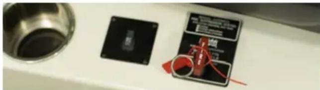
In an automatic/manual system, ensure the pin inserted to protect the system at the helm during transit from the factory has been pulled to activate the system. This is part of dealer preparation, but it is the responsibility of the boat owner to ensure that the system is functional.
FIRE SUPPRESSION AND EXTINGUISHING
All MasterCraft boats are equipped with an automatic fire suppression system. The automatic system operates from sensors in the engine room and will automatically release a clean-agent, gaseous chemical that does not leave residue behind. In boats sold domestically and some internationally, this is the HFC-227 system.
It is also possible to activate the system manually on the domestic boats only. Pull the pin with the red tag, and then pull the red fire handle to set the system in operation. (International boats are automatic only.)
natural_image
Close-up of a kitchen sink with a black CPU socket and a red-labeled electronic device (no visible text or symbols)In case of an engine compartment fire, shut down the engine and blowers before manual discharge, or immediately following the automatic discharge. Boats are equipped with a discharge indication light at the instrument panel or on the video display gauge at the helm.
After the suppression system has been used, the fire extinguisher canister will be empty. The boat owner/operator should have the canister replaced as soon as possible.
MasterCraft boats have also been specified to carry a hand-held 2.5 lb. monoammonium phosphate expellant (dry chemical) unit, which is rated Class A (trash, wood and paper), Class B (flammable liquids, fuel, gas) and Class C (energized electrical equipment). These units should be used in situations other than engine compartment fires.
Hand-held units should be replaced or recharged as soon as possible after use. Chemical discharge should be cleaned from all surfaces as soon as possible and prior to running the boat again, unless operation is necessary to return to shore.
The boat should never be operated following a fire until after a determination has been made whether operation may result in another fire. If any danger of an additional fire exists, the boat should be towed to shore or dock rather than running the engine(s).
Consumers who choose to purchase fire control equipment from resources other than MasterCraft must follow the instructions and requirements as listed within the engine compartment regarding suitability for the compartment volume. These standards are established by the Coast Guard Code of Federal Regulations (CFR) and the American Boat and Yacht Council (ABYC).

DANGER
Following the activation of the automatic fire suppression system or a hand-held fire extinguisher, a careful determination should be made as to whether the boat can safely be operated. If there is any doubt or concern whatsoever, the boat should be towed to shore and/or dock for service by an authorized MasterCraft dealer prior to operating again. Failure to follow these instructions could result in death or serious injury/illness.
CAPSIZING
In addition to fire, a boater's greatest concern may be with the possibility of capsizing or overturning the boat. A number of factors can occur that will result in a boat overturning (high waves, excessive wakes, bad weather) or sinking as a result of damage such as striking an underwater object or another boat.
In the event of such an occurrence, try to turn the engine OFF. Attempt to locate any other people who were on-board and determine whether they are injured. Unless there is fire or release of gasoline, in most instances it is wise to remain with the boat. Except the cases of sinkable damage, it will float. Climbing on the hull will make it easier for rescuers to locate you and others.
RUNNING AGROUND OR STRIKING UNDERWATER OBJECTS
Ascertain whether there is damage to the hull. If water can be stopped from entering the boat, cautiously return to dock. Have the boat checked out by your authorized MasterCraft dealer to be certain that the hull has not been weakened. Even if water does not intrude initially, difficulties may occur later.
If water is entering the boat after running aground or striking an underwater object, call or signal for assistance. Abandon ship, if necessary. Do not attempt to out-run a significant leak to shore as it can be difficult to estimate how long it will take for enough water to intrude and sink the boat.
IN-WATER ACTIVITIES SAFETY
Individuals in the water are obligated to be as aware of the fundamental safety rules as operators. If you are new to water sports, you should seek certified training before starting. You may find it especially helpful to join a local water-sports club, if available, and the U.S.W.S.A. (United States Water Skiing Association).
• Always remember that the majority of in-water injuries are the result of impacts with other objects, so always look where you are going and be aware of what is going on around you.

DANGER
PROPELLER(S) MAY CAUSE SERIOUS INJURY OR DEATH. Shut off the engine(s) when near persons in the water, prior to using sunpads, swim platform or boarding ladder.
- Never put your arm, head or any other part of your body through the handle/bridle of the ski or wakeboarding line, nor wrap the line around any part of the body at any time.
- Never ski, wakeboard, wake surf or engage in tubing at night.
- Never ski, wakeboard, wake surf or engage in tubing directly in front of other boats.
When adding accessories to the tower, ensure that the total aggregate weight of the accessories does not exceed 85 lbs. (U.S.). Exceeding the limit may result in structural failure of the tower. MasterCraft strongly encourages the use of MasterCraft towers and accessories only as they have been tested and determined to meet product requirements, including weight.

CAUTION
Towers should never have a total aggregate weight of accessories exceeding 85 lbs. (U.S.). Excessive weight can cause tower failure and the collapse of a tower or the disconnection of the tower from the deck, which could result in serious bodily injury or damage to the boat that is not covered by warranty.
- Never attempt to fold a ZFT0 tower without assistance. Folding a ZFT0 tower requires at least two (2) people. (The ZFT4 and ZFT5P towers are not included in this group.)
- Never jump from a boat that is moving at any speed, nor enter or exit the water when the engine is running (ON). (See the Common Sense Approach section of this Owner's Manual for additional information regarding carbon monoxide peril.)

DANGER
Maintain a distance of at least six (6) feet from the ski platform when wake surfing or tubing. Any closer risks exposure to CO fumes, which can be deadly. Never launch a surfboard from the ski platform (or any part of the boat) or end a surfing session by surfing onto the ski platform. Such activities can damage the boat, which is not covered under warranty. Being on the ski platform at any time the boat is running can potentially expose individuals to CO poisoning as well.
- Never ride on the ski platform or hold on to the ski platform while in the water during engine operation, including at idle. Carbon monoxide fumes are expelled from the lower transom areas of your boat and can cause death or serious illness. See the Common Sense Approach section following for more details.
- Never climb, sit or stand on a tower. The tower is intended for towing only as noted.
- Make sure that everyone knows and uses approved skiing/wakeboarding hand signals and adheres to common skiing, wakeboarding and boating courtesy. Inexperienced skiers might not know that there are waterskiing hand signals, similar to bicycle and motorcycle hand signals, that can be used while skiing. For example, giving a thumbs up or palm facing up signal while motioning upwards means "speed up," and the opposite, thumbs down or palms facing down, means "slow down." There are also signals for speed—turn right, turn left, stop—and signals for
when you are down in the water. Learning these help the water skier communicate with the boat over the loud roar of the engine. The best way to utilize these signals is by having a spotter. Many states require at least two people be aboard the boat while towing a skier—one driver and one spotter. Having a spotter to watch the water skier allows the driver of the boat to concentrate on the water in front of and around the boat. The spotter watches the water skier and communicates hand signals to the driver and also can alert the driver when the skier falls.
- Give immediate assistance to anyone who falls because they are vulnerable and may not be seen by other boaters. Approach individuals in the water from the leeward side (opposite the wind) and turn OFF the engine prior to reaching them. Propellers and engine exhaust are only part of the potential problem for someone in the water. Be aware that propellers may continue to turn for a period of time after the engine is shut OFF, and the edges are often sharp enough to easily cut skin or break bones.
- Ski and wakeboard only in acceptable areas. Avoid restricted areas.
- The above mandates are not all-inclusive. It is the boater's responsibility to operate the boat in a safe fashion and become familiar with any and all rules and regulations governing boat operation.

DANGER
Do not tow more than two (2) persons at one time on a tow tower. The tow tower approved for use on your boat should be used only for water skis, wakeboards, surfboards or recreational two-person towables, and not for parasailing, kite flying or towing other boats. Do not add any attachments that are not approved for use on your MasterCraft boat. Do not climb on, sit on, stand on, jump off of or dive off of the tower. Never allow passengers to sit behind the tow rope attachment point. Never allow loose tow rope ends to dangle. Always be certain that all bolts are in place and tight before and during use. When the tower is up, watch for low obstacles such as tree limbs, bridges or power lines.

natural_image
Two people relaxing on a small boat at sunset, smiling and enjoying (no text or symbols visible)EQUIPMENT
SAFETY EQUIPMENT
Federal law requires certain safety equipment to be on-board your boat at all times. Responsible boaters carry additional equipment in case of emergency. It is your responsibility to check with the local boating authorities for any additional requirements and/or equipment over and above the federal requirements.
REQUIRED EQUIPMENT
Your MasterCraft boat was equipped at the factory with most of the federally required safety equipment for inland waters (Class II, 26-foot-to-40-foot watercraft). This equipment includes:
- ABYC-approved (American Boat & Yacht Club) marine mufflers with water injection
• USCG-approved (United States Coast Guard) marine flame arrestor
• USCG-approved engine box ventilation with sparkless blower
• ABYC-approved electric horn sound-warning device
• USCG-approved inland lighting
• Automatic and manual fire extinguishers
RECOMMENDED EQUIPMENT
The responsible boat owner will avoid potential problems on an outing by having additional equipment on board. Normally, the decision regarding the appropriate equipment to take on individual outings is dependent upon the body of water and the length of the trip. We suggest the following equipment as a minimum (your MasterCraft dealer can also assist you with additional recommendations):
- Anchor with at least 75 feet of line (in saltwater operation, particularly)
- Manual bailing device for removing water
• Combination oar/boat hook
• Day-and-night visual distress signal - First aid kit and manual
• Airway breathing tube - Waterproof flashlight
• Non-electric horn or whistle - Set of local navigational charts
- Mooring lines and fenders
- Extra engine oil
- Tool kit
- Portable, battery-operated AM/FM radio or weather radio/scanner
SOUND PRODUCING DEVICES
The navigation rules require sound signals to be made under certain circumstances. Meeting, crossing and overtaking situations, which will be described in some detail shortly, are examples of when sound signals are required. Recreational vessels are also required to sound signals during periods of reduced visibility. Your MasterCraft boat is equipped with a horn, but you may also purchase aftermaket devices in case of potential electrical disconnect or failure.
The following are standard signals when using a whistle:
• One prolonged blast: WARNING.
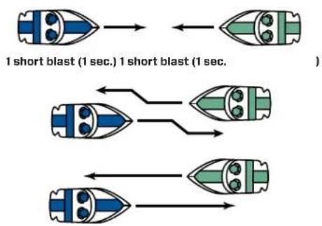
• One short blast: PASS ON MY PORT SIDE.
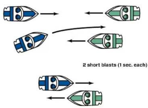
- Two short blasts: PASS ON MY STARBOARD SIDE.
• Three short blasts: MY ENGINES ARE IN REVERSE.
- Five or more blasts: DANGER!
NOTE: The requirement to carry a bell on board no longer applies to vessels operating on International Waters.
VISUAL DISTRESS SIGNALS
All vessels used on coastal waters, the Great Lakes, territorial seas and those waters connected directly to them up to a point where
a body of water is greater than two miles wide, must be equipped with U.S.C.G.-approved visual distress signals. Vessels owned in the United States but operating on the high seas must be equipped with U.S.C.G.-approved visual distress signals.
Pyrotechnic visual distress signals must be Coast Guard-approved, in serviceable condition and readily accessible. This means that:
- They are marked with an expiration date. Expired signals may be carried as extra equipment, but cannot be counted toward meeting the visual distress signal requirement, since they may be unreliable.
- If pyrotechnic devices are selected, a minimum of three are required. That is, three signals for day use and three signals for night. Some pyrotechnic signals meet both day and night use requirements.
- Pyrotechnic devices should be stored in a cool, dry location, if possible. A watertight container painted red or orange and prominently marked "Distress Signals" or "Flares" is recommended.
U.S.C.G.-approved pyrotechnic visual distress signals and associated devices include pyrotechnic red flares, hand-held or aerial; pyrotechnic orange smoke, hand-held or floating, or launchers for aerial red meteors or parachute flares.
Non-pyrotechnic devices may be allowed. These include an orange distress flag (day signal only) or an electric distress light (which is acceptable for night use). Use of these devices must still meet Coast Guard requirements, information for which is available online and from the Coast Guard.
Under Inland Navigation Rules, a high intensity white light flashing at regular intervals from 50-70 times per minute is considered a distress signal. Such devices do NOT count toward meeting the visual distress signal requirement, however. Regulations prohibit display of visual distress signals on the water under any circumstances except when assistance is required to prevent immediate or potential danger to persons on board a vessel.
All distress signals have distinct advantages. No single device is ideal under all conditions or suitable for all purposes. Pyrotechnics are universally recognized as excellent distress signals. However, there is potential for injury and property damage if not properly handled. Particular care should be used in stowage of pyrotechnics if children will be on board. These devices produce a very hot flame and the residue can cause burns and ignite flammable materials.
Check with local authorities regarding the best visual distress signal for use in the area in which you will be boating.

text_image
River Bay Open Water VDS NOT REQUIRED Less than 2 miles VDS REQUIREDVDS Requirements
NAVIGATIONAL LIGHTS
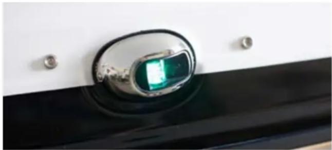
Your MasterCraft boat is equipped with navigational lights. See the Guide to Individual Models section to determine the location of the navigational lights on your boat or verify with your dealer.
Anytime you are moving on the water between sunset and sunrise, you are required to have your navigational lights operating.
natural_image
Close-up of a small electronic device with a green lens and metallic casing, mounted on a black surface (no visible text or symbols)WARNING PLATES AND LABELS
Read and note ALL warning plates and labels from bow to stern, including those that are installed inside the engine compartment, lockers and under seating.
YOU MUST READ AND ADHERE TO ALL CAUTIONS AND WARNINGS IN AND ON YOUR BOAT!

natural_image
Girl surfing on a small boat in turbulent ocean waves, smiling and waving (no text or symbols visible)LEGAL REQUIREMENTS
LAW ENFORCEMENT
A vessel underway, when hailed by a Coast Guard vessel, is required to heave to, or maneuver in such a manner that permits a boarding officer to come aboard.
Other federal, state and local law enforcement officials may board and examine a vessel. The Coast Guard may impose a civil penalty up to \1,000 for failure to comply with equipment requirements; failure to report a boating accident; or comply with other federal regulations. Failure to comply with the Inland Navigation Rules Act of 1980 can result in a civil penalty up to \5,000. Details of the Act are available online or through the U.S. Coast Guard and the Coast Guard Auxiliary.
OPERATOR'S LICENSE
Some states are implementing operator's license requirements. These requirements vary widely. Many states now have restrictions regarding age. If you are operating in a location where minors are allowed to operate the boat, careful supervision by an adult should be the rule of thumb always. Whether operating a boat locally or in a remote location, operators should annually verify with state and local authorities regarding whether a license or training is required.
BOATING UNDER THE INFLUENCE
Boating under the influence of alcohol or drugs can be as deadly as driving a car while under the influence!
Did you know:
- a boat operator is likely to become impaired more quickly than a vehicle driver, drink for drink?
- the penalties for BUI can include large fines, revocation of operator privileges and serious jail time?
- the use of alcohol is involved in about one-third of all recreational boating fatalities?
It is illegal to operate a boat while under the influence of alcohol or drugs in every state. The Coast Guard also enforces a federal law that prohibits BUI.
Alcohol affects judgment, vision, balance and coordination. These impairments increase the likelihood of accidents afloat for both boat operators and passengers. U.S. Coast Guard data shows that in boating deaths involving alcohol use, over half the victims capsized their boats and/or fell overboard.
Alcohol is even more hazardous on the water than on land. The marine environment of motion, vibration, engine noise, sun, wind and spray accelerate a drinker's impairment. These stressors cause fatigue that makes a boat operator's coordination, judgment and reaction time decline even faster when using alcohol.
As a result of alcohol's effects, a boat operator with a blood alcohol concentration of approximately .10 percent is estimated to be more than 10 times as likely to die in a boating accident than an operator with zero blood alcohol concentration. Passengers are also at greatly increased risk for injury or death, especially if they are also using alcohol.
The Coast Guard and every state have stringent penalties for violating BUI laws. Penalties can include large fines, suspension or revocation of boat operator privileges, and jail time. The Coast Guard and the states cooperate fully in enforcement in order to remove impaired boat operators from the waters.
In waters that are overseen solely by the states, the states have the authority to enforce their own BUI statutes. In state waters that are also subject to U.S. jurisdiction, there is concurrent jurisdiction. That means if a boater is apprehended under Federal law in these waters, the Coast Guard will (unless precluded by state law) request that state law enforcement officers take the intoxicated boater into custody. Depending on the circumstances, the operator may be arrested. Penalties vary, but in many jurisdictions operators found guilty of BUI can expect a civil penalty of at least \1,000 or criminal penalty of \5,000, one year of imprisonment or both. Civil lawsuits in cases of property damage or injury/death to others can result in significantly more serious penalties.
Intoxication from drugs, including legal prescription drugs, is an equally serious matter and is dealt with as seriously as alcohol.
REGISTRATION, NUMBERING AND DOCUMENTATION
Although it might not be immediately obvious as to how this relates to boating safety, in fact it can be critical in emergencies. All undocumented vessels equipped with propulsion machinery must be registered in the state of principal use. A certificate of number will be issued upon registering the vehicle. These numbers must be displayed on your vessel. The owner/operator of the vessel must carry a valid certificate of number whenever the vessel is in use. When moving to a new state of principal use, the certificate is valid for 60 days. Check with your state boating authority for registration requirements.
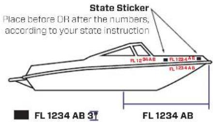
Numbers must be painted or permanently attached to each side of the forward half of the vessel. The validation stickers must be affixed within six inches of the registration number. With the exception of the vessel fee decal, no other letters or numbers may be displayed nearby. Lettering must be in plain, vertical block characters of not less than three (3) inches in height. Spaces or hyphens between letter and number groupings must be equal to the width of a letter other than "i" or a number other than "1."
The owner of a vessel must notify the agency which issued the certificate of number within fifteen (15) days if the vessel is transferred, destroyed, abandoned, lost, stolen or recovered, or if the certificate of number is lost, destroyed or the owner's address changed. If the certificate of number becomes invalid for any reason, it must be surrendered in the manner prescribed to the issuing authority within 15 days.
text_image
State Sticker Place before OR after the numbers, according to your state instruction FL 1234 AB FL 1234 AB FL 1234 AB FL 1234 AB FL 1234 ABACCIDENT REPORTING
Federal law requires the boat operator to file a boating accident report with the state reporting authority when, as a result of an occurrence that involves a boat or its equipment:
• A Person dies
• A Person disappears from the vessel under circumstances that indicate death or injury
- A Person is injured and requires medical treatment beyond first aid
- Damage to vessels and other property totals \$2,000 or more (the amount may be lower in some states and territories; verify with local boating authorities)
- The Boat is destroyed
If the boat operator is deceased or unable to make the report, the boat owner is required to file the report.
Your responsibility does not end with your own craft. You are required by law to respond to any distress signal, visual or auditory. Render immediate assistance, EXCEPT in instances in which you and your passengers will be endangered or those situations that exceed your capabilities or the capabilities of your boat. Good Samaritan protection is provided to boaters who provide good faith assistance and protects them from civil liability for assistance given.
SPEEDING AND NOISE
Some states and boating areas have imposed speed limits for operation of boats, including but not limited to no-wake zones. Noise regulations may also be imposed. It is the responsibility of the boat operator to be familiar with any and all laws and regulations and to obey them. The U.S. Coast Guard is an excellent source for this information, including penalties for failure to observe the requirements.
RADIOS—TELEPHONES
Improper use of a radio-telephone is a criminal offense. The use of obscene, indecent or profane language during radio communications is punishable by a \$10,000 fine, imprisonment for two years or both. Other penalties exist for misuse of a radio, such as improper use of Channel 16 VHF-FM, a calling and distress channel. It is not to be used for conversation or radio checks. Such communications should be conducted on an authorized channel.
REFUSE AND POLLUTION
There are stringent requirements regarding pollution, discharge of oil, discharge of garbage and the operation and discharge from sanitation devices. It is the boat owner's and operator's responsibility to determine laws and regulations and to ensure that those laws and regulations are respected and enforced.
Details are available through the U.S. Coast Guard.
The preceding information provides requirements within the United States territorial waters. Boats operated under other autonomous governmental agencies throughout the world will have their own legal requirements, including the international MARPOL Treaty.
natural_image
Interior view of a car's airway with a water drain and mechanical components (no visible text or symbols)Boat owners and operators are responsible for determining what those requirements are and complying with them, regardless of the owner/operator's citizenship.
This Owner's Manual was developed to help ensure an enjoyable boating experience with a fabulous MasterCraft boat. As stated earlier, this information is not all-inclusive. There are many factors to consider and additional information that you need to research before undertaking any boating activity.
In addition to reading this Owner's Manual and other related material, and familiarizing yourself with the proper operation of the MasterCraft boat, always use common sense when boating.
natural_image
Woman relaxing in a blue watercraft with children nearby, no visible text or symbols on the main subjects.OTHER IMPORTANT INFORMATION
COMMUNICATIONS
The following applies to the Great Lakes and salt water boating:
When boating off-shore, carry communications gear such as a marine VHF-FM and/or HF transceiver(s), appropriate to the operating area. Cellular phone coverage is available in many coastal areas. However, cellular phones should NOT be considered a substitute for VHF-FM marine band radios for emergency purposes.
In distress situations, press the VHF transmit button and clearly say: MAYDAY, MAYDAY, MAYDAY. Follow this with the vessel name and/or description, the location, nature of emergency and number of people on-board. Then release the transmit button and wait for 10 seconds. If there is no response, repeat the MAYDAY call.
Satellite EPIRBs (406 MHz) are designed to quickly and reliably alert rescue forces, indicate an accurate distress position, and guide rescue units to the distress scene, even when all other communications fail.
When activated, the satellite EPIRB transmits a distress signal with a beacon-unique identifying code. The system detects the signal, calculates an accurate distress position, checks the unique identifying code against the EPIRB registration database (vessel and point of contact information supplied by the owner) and routes the
distress alert with registration information to the responsible U.S. Coast Guard (or International) Rescue Coordination Center (RCC).
406MHz EPIRBs with GPS (internal or attached) also provide an immediate GPS position in the information passed to the RCC.
Geostationary satellites make detection almost immediate. If the EPIRB does not have the ability to provide a GPS position, the process to determine a position takes about an hour on average and almost always less than two hours. Satellite EPIRBs also include a homing beacon and strobe to help rescue forces quickly locate the distress scene.
Satellite beacons have significant coverage, alerting timeliness, position accuracy, and signaling advantages over other types of EPIRBs (121.5 MHz). Before purchasing or using something other than the 406 MHz EPIRB, be sure to understand the capabilities and limitations.
Further information and a complete listing of VHF channels and frequencies is available at: www.navcen.uscg.gov.
INSURANCE
Even if someone else is operating the boat, the owner is generally held liable for any damages or injuries that occur. It is in the owner's best interest to maintain sufficient personal liability and property damage insurance on the boat in anticipation of potential judgments. Guarding against theft is another consideration.
WEATHER
Never leave the dock without first checking the local weather forecast. Weather information is available from television, radio, local newspaper, online or from a weather channel on a VHF radio.
At certain times of the year, weather can change rapidly and boaters should always keep an eye out for weather conditions.
While boating, pay attention to the following:
- Watch for cloud build-up, especially rapid, vertically rising clouds.
- Sudden drop in temperature.
- Sudden change in wind direction and/or speed.
- On-board barometers, where placed on-board by the boat owner, should be checked every two-to-three hours. A rising barometer indicates fair weather and a rise in wind velocity; a falling barometer indicates stormy or rainy weather.
What to do in severe weather:
- Reduce speed, keeping enough power to maintain headway.
- Put on PFDs.
- Turn on running lights.
- Head for the nearest shore or safe harbor that is safe to approach, if possible.
- Head bow of boat into waves at 45-degree angle, if possible.
- Keep bilges free of water.
- Seat passengers on bottom of the boat, near the centerline.
- If the engine fails, tie a sea anchor on a line from the bow of the boat to keep the boat headed into the waves. A bucket will work as a sea anchor in an emergency.
- Anchor the boat, if necessary.
- Seek shelter on-shore whenever possible. Particularly avoid riding out a storm that includes high wind and/or lightning, which is especially dangerous. Avoid contact with metal portions of the boat such as handrails, windshields, tower and cleats.
NAUTICAL CHARTS
Nautical charts are especially important to boaters planning trips, particularly on open waters. These charts show the nature and shape of the coast, depths of water, general configuration and character of the bottom of the body of water. Other markings on the nautical charts include prominent landmarks, port facilities, aids to navigation, and marine hazards. Changes brought about by people and nature require that nautical charts be constantly maintained and updated to aid safe navigation.
National Ocean Service (NOS) charts may be purchased either directly by mail from the NOS Distribution Branch or through an authorized agent. There are more than 1,700 nautical chart agents who sell them.
FAA/NATIONAL AERONAUTICAL CHARTING OFFICE
Distribution Division, AVN-530
6303 Ivy Lane, Suite 400
Greenbelt, MD 20770
Telephone: (301) 436-8301
Email: 9-AMC-chartsales@faa.gov
http://naco.faa.gov/
FLOAT PLAN
A “float plan” is a written record indicating the planned destination and approximate length of time for the outing. Sample forms are available at the Coast Guard's website. One should be completed and left with a relative or friend prior to each trip. In case of an emergency or failure to return within a reasonable period of time, pertinent information will be available to assist local marine police or the Coast Guard in determining whether a search should be performed. Be sure to notify the float plan holder upon return.
STAYING AFLOAT
It is commonly believed that someone dressed in heavy clothing or waders will experience considerably more difficulty staying afloat if they fall overboard. This is not true. Air trapped in clothing provides flotation and bending the knees will trap air in waders.
To stay afloat:
- Remain calm. Do not thrash about or try to remove clothing or footwear. This leads to exhaustion and increases the loss of air that may keep you afloat.
- Keep your PFD on.
- Keep your knees bent.
- Float on your back and paddle slowly to safety.
COLD WATER SURVIVAL
Sudden immersion in cold water can induce rapid, uncontrolled breathing, cardiac arrest and other physical body conditions, which can lead to drowning. Always wearing a PFD will help survival in rapid immersion situations.
In other situations when entry into cold water is necessary:
- Wear a PFD.
- Button all clothing.
- Cover your head if possible and enter the water slowly.
- Keep your head out of the water if at all possible.
- Assume the Heat Escape Lessening Posture (HELP) position as taught within a Coast Guard-taught safety course. Information about HELP is available online.
Immersion in water speeds the loss of body heat and can lead to hypothermia, the abnormal lowering of internal body temperature. If a boat capsizes, it will likely float on or just below the surface.
To reduce the effects of hypothermia, get in or on the boat. Try to get as much of your body out of the water as possible. If you can't get in the boat, a PFD will enable you to keep your head out of the water. This is very important because about 50 percent of body heat loss is from the head.
It may be possible to revive a drowning victim who has been under water for some time and shows no sign of life. Cases document instances where victims have been resuscitated after extended periods. Start CPR immediately and get the victim to a hospital as quickly as possible.
Immersion suits will delay the effects of hypothermia in cold water and are available through many retailers who specialize in sales of marine products. The suits should be stored and maintained according to the manufacturer's instructions.
INFLATABLE LIFE RAFTS
An inflatable life raft can provide a survival platform for an extended period of time. Be sure the life raft is large enough for everyone on board when the boat operates off-shore. It should have the appropriate emergency equipment pack and should be professionally serviced periodically, according to the manufacturer's instructions. Coast Guard-approved life rafts must meet a number of stringent material and performance standards.
ANCHORING
Anchoring is done for two principal reasons: first, to stop for fishing, swimming, lunch or an overnight stay, and secondly, to keep a boat from running aground in bad weather or as a result of engine failure.
When preparing to anchor, bring the bow of the vessel into the wind or current. Place the engine in neutral. When the boat comes to a stop, slowly lower the anchor. Do not throw the anchor over as it will tend to foul the anchor or tangle line. When the anchor line has been let out, back up away from the anchor with the engine in idle reverse to help set the anchor. After it is firmly set, use reference points (landmarks) in relation to the boat to be sure that the boat is not drifting. Check the points frequently.
RULES OF THE OPEN WATER
Just as there are rules that apply when driving a vehicle on the street, there are waterway rules that apply when you are driving a boat on the water. These rules are used internationally, and they are enforced by the United States Coast Guard and local agencies. You should be aware of these rules and follow them whenever you encounter another vessel on the water.
In various geographic locations, certain rules prevail that may be unique to the locale. Each state also has laws and boating limitations that may be applicable only within their boundaries. It is the operator's responsibility to seek out this information and become familiar with all safety-related information, laws and rules governing boating operation.
The rules presented in this Owner's Manual are condensed and have been provided for convenience only. Consult your local U.S. Coast Guard Auxiliary (USCGA), Department of Motor Vehicles (DMV) or Department of Natural Resources (DNR) for a complete set of rules governing the waters in which you will be using your boat. If you plan to travel—even for a short trip—you would be well-served to contact the regional USCGA, DMV or DNR in the area where you will be boating. Often, basic information is available through websites sponsored and prepared by these organizations and governing bodies.
STEERING AND SAILING RULES/ SOUND SIGNALS
Any time two (2) vessels on the water meet one another, one vessel has the right-of-way. It is called the stand-on vessel. The vessel that does not have the right-of-way is called the give-way or burdened vessel.
These rules determine which vessel has the right of way, and accordingly, what each vessel should do.
The vessel with the right-of-way has the duty to continue its course and speed, except to avoid an immediate collision. When you maintain your direction and speed, the other vessel will be able to determine how best to avoid you.
The vessel that does not have the right of way has the duty to take positive and timely action to stay out of the way of the stand-on vessel. Normally, the give-way vessel should not cross in front of the stand-on vessel, but should slow down or change direction briefly and pass behind the other vessel. You should always move in such a way that the stand-on operator can see what you are doing if you are operating the give-way vessel.
GENERAL PRUDENTIAL RULE
This rule is called Rule 2 in the International Rules and says, "In obeying and construing these rules due regard shall be had to all dangers of navigation and collision, and to any special circumstances, which may render a departure from the above rules necessary in order to avoid immediate danger."
RULES WHEN ENCOUNTERING VESSELS
There are three (3) main situations in which you may encounter other vessels, and you must avoid a collision. These are:
- Meeting (you are approaching another vessel head-on).
- Crossing (you are traveling across the other vessel's path).
- Overtaking (you are passing or being passed by another vessel).
MEETING
If you are meeting another vessel head-on, and you are close enough to run the risk of collision, neither of you has the right-of-way. Both of you should alter course to avoid an accident. You should keep the other vessel on your port (left) side. (This rule doesn't apply if both of you can clear each other by continuing your set course and speed.)
flowchart
graph TD
    A["Two blue bullet"] --> B["Two green bullet"]
    C["Two blue bullet"] --> D["Two green bullet"]
    E["Two blue bullet"] --> F["Two green bullet"]
    style A fill:#f9f,stroke:#333
    style C fill:#f9f,stroke:#333
    style E fill:#f9f,stroke:#333
    style B fill:#ccf,stroke:#333
    style D fill:#ccf,stroke:#333
    style F fill:#ccf,stroke:#333
    note right of B: "2 short blasts (1 sec. each)"
    note right of F: "2 short blasts (1 sec. each)"
flowchart
graph LR
    A["1 short blast (1 sec.)"] --> B["1 short blast (1 sec.)"]
    B --> C["1 short blast (1 sec.)"]
CROSSING
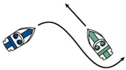
When two (2) power-driven vessels are crossing each other's path close enough to run the risk of collision, the vessel that views the crossing vessel to the starboard (right) side must give way.
If the other vessel is to the port (left) side, you are the stand-on vessel, and provided the other vessel gives you the right-of-way, maintain your course and direction.
natural_image
Two stylized rocket illustrations with blue and green design, connected by curved arrows (no text or symbols)OVERTAKING
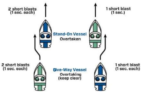
If you are passing another vessel, you are the give-way vessel. This means that the other vessel is expected to maintain its course and speed. You must stay out of its way as you clear it, altering course and speed as necessary.
Conversely, if you are being passed by another vessel, you are the stand-on vessel, and you should maintain your speed and direction so that the vessel can be steered around you.
flowchart
graph TD
    A["Stand-On Vessel Overtaken"] --> B["2 short blasts (1 sec. each)"]
    A --> C["1 short blast (1 sec.)"]
    D["Give-Way Vessel Overtaking (keep clear)"] --> E["2 short blasts (1 sec. each)"]
    D --> F["1 short blast (1 sec.)"]
SAILING VESSEL RIGHT-OF-WAY
Sailing vessels should normally be given the right-of-way.
The exceptions to this are:
- When the sailing vessel is overtaking the power-driven vessel, the power-driven vessel has the right-of-way.
- Sailing vessels should keep clear of any fishing vessel.
- In a narrow channel, a sailing vessel should not hamper the safe passage of a power-driven vessel that can navigate only in such a channel. A sailing vessel that is underway but not using sails is considered a power vessel and should be treated like any other power vessel when determining right of way.
FISHING VESSEL RIGHT-OF-WAY
Under international rules, all vessels that are fishing with nets, lines or trawls are considered to be fishing vessels; however, boats with trolling lines are not considered fishing vessels.
Fishing vessels have the right of way, regardless of position, but these vessels cannot impede the passage of other vessels in narrow channels.
OTHER SPECIAL SITUATIONS
There are additional rules to remember when operating your boat around other vessels, such as:
- When navigating in narrow channels, you should keep to the right when it is safe and practical to do so.
- When preparing to go around a bend that may obstruct your view of other water vessels, you should sound a prolonged blast on the horn or with a whistle for four (4) to six (6) seconds. Even if no reply is heard, you should still proceed around the bend with caution.
READING BUOYS AND OTHER MARKERS
The waters of the United States are marked for safe navigation by the lateral system of buoyage. The markers and buoys you encounter will have an arrangement of shapes, colors, numbers and lights to show which side of the buoy a boater should pass when navigating in a particular direction.
The Uniform State Waterway Marker System has been devised for these waters. This system uses buoys and signs with distinctive shapes and colors to show regulatory or advisory information. The markings on these buoys are oriented from the perspective of being entered from a seaward direction while the boater is going toward the port. Red buoys are passed on the starboard (right) side when proceeding from open water into port, and green buoys are passed on the port (left) side. When navigating out of port, your position to the buoys should be reversed: red buoys to port (left) and green buoys to starboard (right).
Uniform State Waterway Marker System
Green or Black Channel Marker Buoy: Traveling upstream, you should pass to the right of the buoy as it marks the left side of the channel.
Red Channel Marker Buoy: Traveling upstream, you should pass to the left of this buoy as it marks the right side of the channel.
Junction Buoy (Green over Red): Means two channels are coming together and you should pass to the right of the buoy as you travel upstream.
Junction Buoy (Red over Green): Means two channels are coming together and you should pass to the left of the buoy as you travel upstream.
Passing Daymark (Green): A sign mounted on poles in the water or on the bank which is used in the same manner as a channel marker buoy. In this case it marks the left side of the channel as you travel upstream.
Passing Daymark (Red): A sign mounted on poles in the water or on the bank which is used in the same manner as a channel marker buoy. In this case it marks the right side of the channel as you travel upstream.
Channel Crossing Daymark (Green): A sign mounted on poles in the water or on the bank which means the channel is crossing from the left bank to the right bank as you travel upstream.
Channel Crossing Daymark (Red): A sign mounted on poles in the water or on the bank which means the channel is crossing from the right bank to the left bank as you travel upstream.
Boats Keep Out Buoy: Marks a swimming area, an area near a dam or any area where boats are not allowed.
Danger Buoy: Marks an obstruction, ferry cable, or any area where boats should not navigate or should use extreme caution.
Information Buoy: Used to relay information. Words printed in black (usually inside the border) tell place names, distances, directional arrows, availability of supplies, gasoline, etc.
Control Buoy: Marks a restricted area such as "slow no-wake," "5 MPH, no skiing or no fishing."
Mooring Buoy: Means an anchor buoy. This is the only buoy to which a boat may tie or secure to.
Diver's Flag: Must be used any time a diver is in the water. Boats must not come closer than 50 feet of the flag and must operate at a slow, no-wake speed within 200 feet.
Alpha Flag: Means a vessel is engaged in diving operations or is restricted in its ability to navigate. Boaters must use extreme caution and are advised to look for a diver's-down flag.
NOTE: Markings may vary by geographic location. For example, the Western Rivers System markers are slightly different, as well as in different states or jurisdictions. Always consult appropriate boating authorities before boating in unfamiliar waters.
text_image
MasterCAHITX2016 MODEL
FEATURES AND SPECS
$$ \frac{1}{2} = \frac{1}{2}\left( \frac{\ln x}{2} - \frac{\ln y}{2} \right) + \frac{1}{2}\left( \frac{\ln z}{2} - \frac{\ln y}{2} \right) $$
text_image
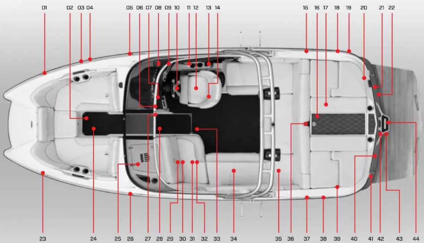
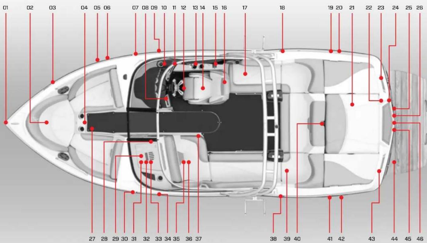
01 02 03 04 05 06 07 08 09 10 11 12 13 14 15 16 17 18 19 20 21 22 23 24 25 26 27 28 29 30 31 32 33 34 35 36 37 38 39 40 41 42 43 44FEATURES
- Bow Cleat
- Ballast tank (beneath floorboard)
- Bilge thru-hull outlet
- Ballast thru-hull vent
- Nav/anchor light
- Amp (below)
- Stereo remote (on dash)
- Circuit breaker panel (on kick panel beneath instrument panel)
- Instrument panel (details in Video Display Gauge section)
- Steering wheel
- Shift/throttle control
- Heated seat (where equipped)
- Fire suppression unit manual override
- Subwoofer
- Bilge thru-hull vent
- Engine compartment
- Auto fire extinguisher
- Stern cleat
- Nav/anchor light (if equipped with tower, the light will be in center aft of tower)
- Shower wand & switch (where equipped, inside compartment)
- Transom stereo remote (where equipped)
- Underwater lights (two, where equipped)
- Bow cleat
- Bow filler cushion (where equipped)
- Glove box
-
Nav/anchor light
-
Adjustable mirror
- Walk-thru seat (where equipped)
- Batteries (under seat)
- Amp (where equipped)
- Hand-held fire extinguisher (beneath observer seat)
- Heated observer seat (where equipped)
- Center drain plug (under inspection plate)
- Cooler (under seat)
- Batteries ON-OFF switch (under seat)
- Ski pylon
- Ballast thru-hull vent
- Fuel tank filler
- Stern cleat
- Engine exhaust
- Surf tabs (on both sides, where equipped)
- Transom drain plug
- Attitude adjustment plate (where equipped)
- Transom rail with tow eye
SPECIFICATIONS
Length of Boat 20' 0"
Width Amidship 96"
Boat Weight 4,300 lbs.
Length of Boat w/Platform 22' 4"
Towing Length 25' 1"
Towing Width 100"
Fuel Capacity 42 gallons
Maximum Capacity 11 people
or 1,446 lbs.
Bow: 4 people or 600 lbs.
Weight must be evenly distributed.
Storage space is located under:
Observer's seat, bow seating, aft and wrap-
around seating, port and starboard sun pads.
X2
text_image
01 02 03 04 05 06 07 08 09 10 11 12 13 14 15 16 17 18 19 20 21 22 23 24 25 26 27 28 29 30 31 32 33 34 35 36 37 38 39 40 41 42 43 44 45 46FEATURES
- Bow cleat
- Anchor storage (under seat)
- Horn
- Ballast tank below floor board
- Bilge thru-hull outlet
- Ballast thru-hull vent
- Navigation light
- Stereo dash remote (where equipped)
- Cleat
- Circuit breaker panel (on kick panel beneath instrument panel)
- Instrument panel (details in Video Display Gauge section)
- Steering wheel
- Shift/throttle control
- Heated seat (where equipped)
- Fire suppression unit manual override
- Subwoofer (where equipped)
- Cooler (under seat)
- Fuel tank fill
- Stern cleat
- Bilge thru-hull vent
- Engine compartment
- Automatic fire extinguisher
- Engine compartment exhaust
- Transom stereo remote (where equipped)
- Underwater lights (two, where equipped)
- Wake adjustment plate (where equipped)
- Bow filler cushion (where equipped)
-
Amp (where equipped)
-
iPod interface (where equipped)
- Navigation light
- Stereo CD Player (inside glove box, where equipped)
- Sirius Satellite Radio (where equipped)
- Glove box
- Cleat
- Hand-held fire extinguisher (inside observer storage)
- Heated observer seat (where equipped)
- Center drain plug (under inspection plate)
- Fuel tank fill
- Batteries (including ON-OFF switch)
- Ski pylon
- Stern cleat
- Ballast thru-hull vent
- Engine compartment exhaust
- Surf tabs (one on each side below transom)
- Transom rail with tow eye
- Transom drain plug
SPECIFICATIONS
Length of Boat 21' 3"
Width Amidship 98"
Boat Weight 4,550 lbs.
Length of Boat w/Platform 23' 7"
Towing Length 26' 5"
Towing Width 102"
Fuel Capacity 50 gallons
Maximum Capacity 14 people or 1,956 lbs.
Bow: 4 people or 600 lbs.
Weight must be evenly distributed.
Storage space is located under:
Observer's seat, bow seating, aft and wrap-
around seating, port and starboard sun pads.
X10
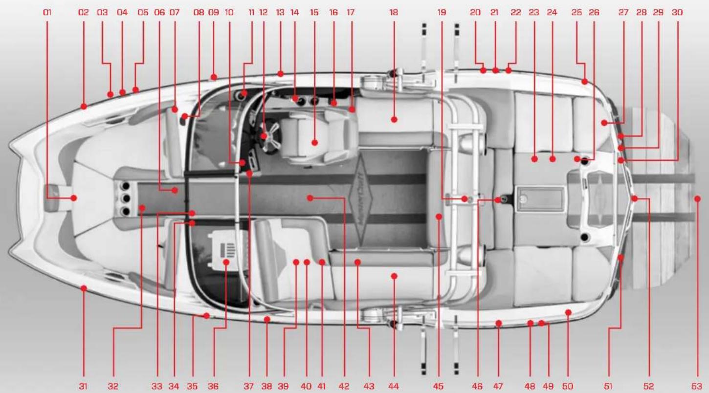
text_image
01 02 03 04 05 06 07 08 09 10 11 12 13 14 15 16 17 18 19 20 21 22 23 24 25 26 27 28 29 30 31 32 33 34 35 36 37 38 39 40 41 42 43 44 45 46 47 48 49 50 51 52 53FEATURES
- Anchor storage
- Bow cleat
- Horn
- Bilge thru-hull outlet
- Ballast thru-hull vent
- Ballast tank (located beneath floorboard)
- Lifting bow backs
- GPS
- Navigation light
- Adjustable mirror
- Instrument panel (details in Video Display Gauge section)
- Steering wheel
- Midship cleat
- Shift-throttle control
- Heated seat (where equipped)
- Fire suppression unit manual override
- Subwoofer (where equipped)
- Cooler (under gas-assisted seat lift)
- Navigation light
- Ballast thru-hull air vent
- Fuel tank filler
- Stern cleat
- Automatic fire extinguisher (inside engine compartment)
- Engine compartment
- Bilge thru-hull vent
- Sea strainer
- Convertible aft seating (both port and starboard)
-
Engine exhaust (under swim platform)
-
Underwater lights (two, where equipped, under swim platform)
- GEN2 Wake Shaping Device (beneath swim platform, both sides)
- Bow cleat
- Bow filler cushion (where equipped)
- Circuit breaker panel (walk-thru side panel)
- Batteries ON-OFF switch (walk-thru side panel
- Navigation light
- Glovebox
- Stereo remote (on clash)
- Mid-ship cleat
- Amp (where equipped, under observer seat)
- Hand-held fire extinguisher (beneath observer seat)
- Observer seat (heated, where equipped)
- Center drain plug (under inspection plate)
- Heater vent (where equipped)
- Batteries (under observer seat)
- Reversible seating (where equipped)
- Removable ski pylon
- Fuel tank filler
- Bilge thru-hull air vent
- Ballast thru-hull air vent
- Stern cleat
- Transom stereo remote (where equipped)
- Center tab plate (under swim platform)
- Under-platform ladder (where equipped)
SPECIFICATIONS
Length of Boat 20' 0"
Width Amidship 98"
Boat Weight 4,800 lbs.
Length of Boat w/Platform 22' 5"
Towing Length 25' 6"
Towing Width 102"
Fuel Capacity 47 gallons
Maximum Capacity 12 people or 1,595 lbs.
Bow: 4 people or 600 lbs.
Weight must be evenly distributed.
Storage space is located under:
Observer's seat, bow seating, aft and wrap-
around seating, port and starboard sun pads.
X20
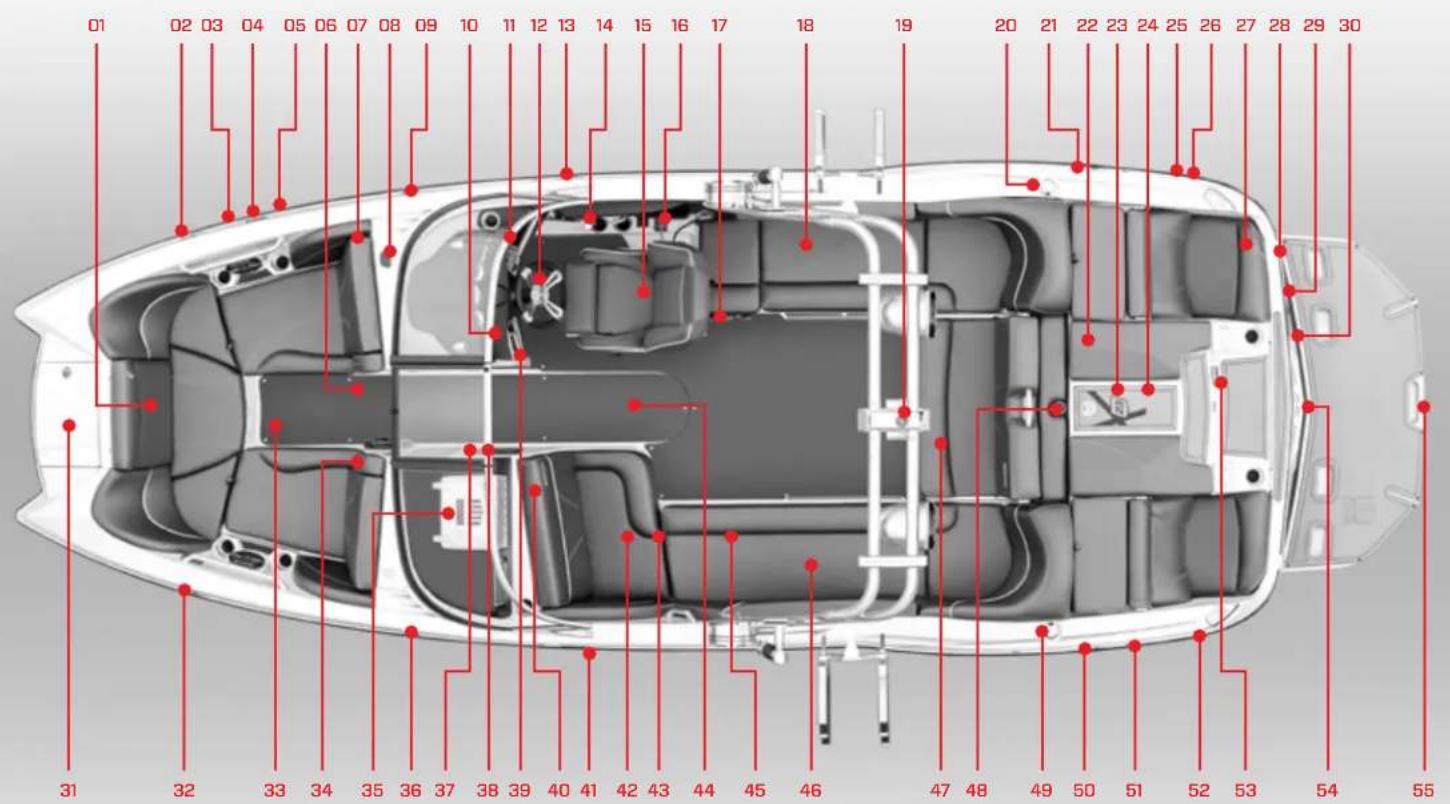
text_image
01 02 03 04 05 06 07 08 09 10 11 12 13 14 15 16 17 18 19 20 21 22 23 24 25 26 27 28 29 30 31 32 33 34 35 36 37 38 39 40 41 42 43 44 45 46 47 48 49 50 51 52 53 54 55FEATURES
-
Anchor storage
-
Bow cleat
-
Horn
-
Bilge thru-hull outlet
-
Ballast thru-hull vent
-
Ballast tank (located beneath floorboard)
-
Lifting bow back
-
GPS puck
-
Navigation light
-
Adjustable mirror
-
Instrument panel
(details in Video Display Gauge section)
-
Steering wheel
-
Midship cleat
-
Shift-throttle control
-
Heated seat (where equipped)
-
Fire suppression unit manual override
-
Subwoofer (where equipped)
-
Cooler (under gas-assisted seat lift)
-
Navigation light
-
Fuel tank fill
-
Stern cleat
-
Automatic fire extinguisher (inside engine compartment)
-
Engine compartment
-
Sea strainer
-
Ballast thru-hull vent
-
Bilge pump
-
Transom lounge seating (as pictured) or standard flip-up transom seating (neither seat for use while underway)
-
Engine exhaust (under swim platform)
-
Underwater lights
(two, where equipped, under swim platform)
-
GEN2 wake shaping device (under swim platform, where equipped)
-
Bow ladder lid
-
Bow cleat
-
Bow filler cushion (where equipped)
-
Flip down armrest
-
Glovebox
-
Navigation light
-
Batteries ON-OFF switch (walk-thru side panel)
-
Circuit breaker panel (walk-thru side panel)
-
Stereo remote (on dash)
-
Amp (where equipped, under observer seat)
-
Mid-ship cleat
-
Hand-held fire extinguisher (beneath observer seat)
-
Observer seat (heated, where equipped)
-
Center drain plug (under inspection plate)
-
Heater vent (where equipped)
-
Batteries (under seat)
-
Reversible seating (where equipped)
-
Removable ski pylon
-
Fuel tank fill
-
Stern cleat
-
Bilge thru-hull air vent
-
Ballast thru-hull air vent
-
Transom stereo remote (where equipped)
-
Wake adjustment plate (under swim platform)
-
Under-platform ladder (where equipped)
SPECIFICATIONS
Length of Boat 22' 9"
Width Amidship 102"
Boat Weight 5,500 lbs.
Length of Boat w/Platform 24' 8"
Towing Length 28' 2"
Towing Width 102"
Fuel Capacity 57 gallons
Maximum Capacity 15 people
or 2,126 lbs.
Bow: 4 people or 600 lbs.
Weight must be evenly distributed.
Storage space is located under:
Observer's seat, bow seating, aft and wrap-
around seating, port and starboard sun pads.
X23
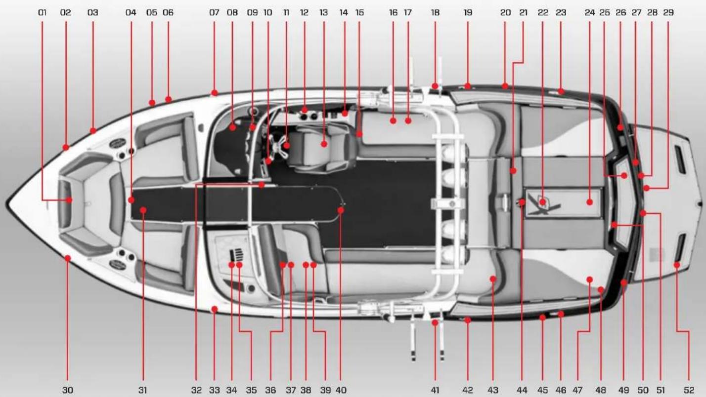
text_image
01 02 03 04 05 06 07 08 09 10 11 12 13 14 15 16 17 18 19 20 21 22 23 24 25 26 27 28 29 30 31 32 33 34 35 36 37 38 39 40 41 42 43 44 45 46 47 48 49 50 51 52FEATURES
-
Anchor storage
-
Bow cleat (where equipped)
-
Horn
-
Ballast tank below floor board
-
Bilge thru-hull outlet
-
Ballast thru-hull vent
-
Navigation light
-
Circuit breaker panel (on kick panel beneath instrument panel)
-
Instrument panel (details in Video Display Gauge section)
-
Stereo remote (on dash)
-
Steering wheel
-
Shift/throttle control
-
Heated seat (where equipped)
-
Fire suppression unit manual override
-
Subwoofer (where equipped)
-
Cooler (under seat)
-
Garbage can
-
Midship cleat
-
Fuel tank filler
-
Bilge thru-hull vent
-
Reversible seating
-
Engine compartment
-
Stern cleat
-
Automatic fire extinguisher
-
Molded-in boarding platform
-
Stern light receptacle (if equipped with tower, the light will be in center aft of tower)
-
Transom stereo remote (where equipped)
-
Underwater lights (two, where equipped)
-
Wake adjustment plate (where equipped)
-
Bow cleat (where equipped)
-
Bow filler cushion (where equipped)
-
Adjustable mirror
-
Navigation light
-
iPod interface (where equipped)
-
Glove box
-
Batteries (under seat)
-
Amp (where equipped)
-
Hand-held fire extinguisher (beneath observer seat)
-
Heated observer seat (where equipped)
-
Center drain plug (under inspection plate)
-
Midship cleat
-
Fuel tank filler
-
Batteries ON-OFF switch (under seat)
-
Ski pylon
-
Ballast thru-hull vent
-
Stern cleat
-
Freshwater tank (where equipped)
-
Shower wand & switch (where equipped, inside compartment)
-
Engine exhaust (each side)
-
Transom rail with tow eye
-
Transom drain plug
-
Teak platform (or fiberglass, where equipped)
SPECIFICATIONS
Length of Boat 23"4'
Width Amidship 102"
Boat Weight 4,700 lbs.
Length of Boat w/Platform 25'7
Towing Length 28' 6"
Towing Width 102"
Fuel Capacity 60 gallons
Maximum Capacity 16 people or 2,219 lbs.
Bow: 5 people or 700 lbs.
Weight must be evenly distributed.
X30
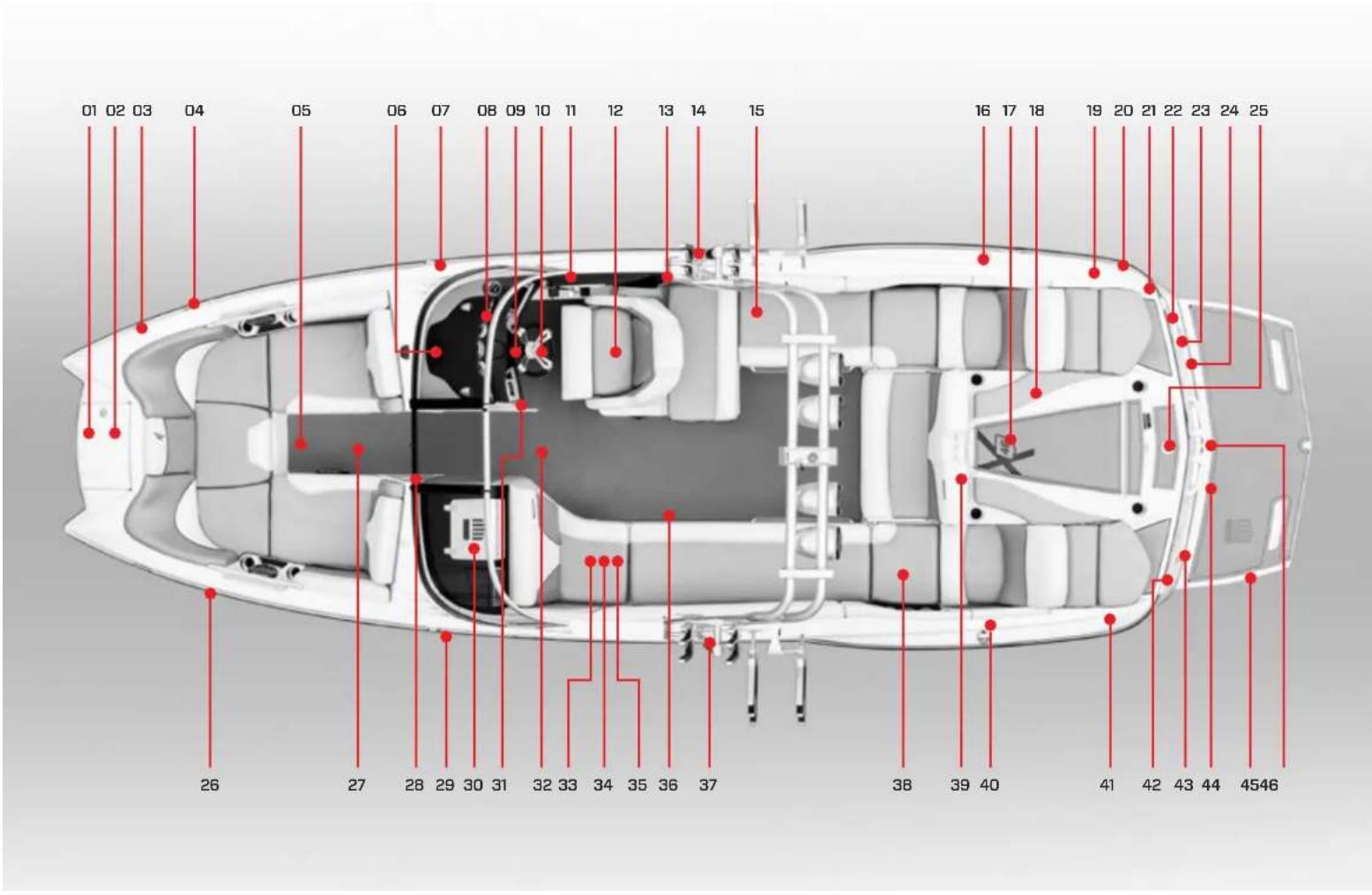
text_image
01 02 03 04 05 06 07 08 09 10 11 12 13 14 15 16 17 18 19 20 21 22 23 24 25 26 27 28 29 30 31 32 33 34 35 36 37 38 39 40 41 42 43 44 4546FEATURES
-
Anchor storage
-
Ladder (where equipped)
-
Bow cleat
-
Horn
-
Ballast tank (beneath floorboard)
-
Circuit breaker panel (on kick panel beneath instrument panel)
-
Navigation light
-
Instrument panel (details in Video Display Gauge section)
-
Adjustable mirror
-
Steering wheel
-
Shift/throttle control
-
Heated seat (where equipped)
-
Fire suppression unit manual override
-
Midship cleat
-
Cooler (under seat)
-
Fuel tank filler
-
Engine compartment
-
Automatic fire extinguisher
-
Engine compartment exhaust (two, on top of port and starboard near transom)
-
Stern cleat
-
Stern light receptacle (if equipped with tower, light will be in center aft of tower)
-
Freshwater flush port (where equipped)
-
Underwater lights (two, where equipped, under swim platform)
-
Transom drain plug (center beneath swim platform)
-
Removable ski pylon (where equipped)
-
Bow cleat
-
Bow filler cushion (where equipped)
-
Amp (where equipped)
-
Navigation light
-
Glove box
-
Stereo remote (on dash)
-
Center drain plug (access plate under carpet mat)
-
Observer seat
-
Subwoofer
-
Batteries (under seat)
-
Washdown connection
-
Midship cleat
-
Battery ON-OFF switch (under seat)
-
Reversible seating
-
Fuel tank filler
-
Stern cleat
-
Freshwater tank fill
-
Surf tabs (each side, under swim platform, where equipped)
-
Wake adjustment plate (under swim platform, where equipped)
-
Swim platform
-
Transom rail with tow eye
SPECIFICATIONS
Length of Boat 24'6"
Width Amidship 102"
Boat Weight 5,350 lbs.
Length of Boat w/Platform 26' 9"
Towing Length 30'10"
Towing Width 102"
Fuel Capacity 79 gallons
Maximum Capacity 15 people
or 2,142 lbs.
Bow: 5 people or 700 lbs.
Weight must be evenly distributed.
Storage space is located under:
Observer's seat, bow seating, aft and wrap-
around seating, port and starboard sun pads.
X46
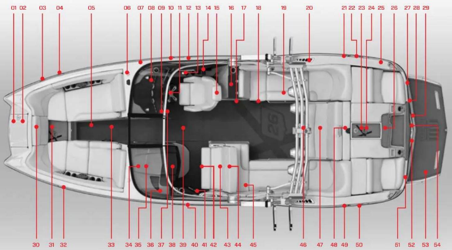
text_image
01 02 03 04 05 06 07 08 09 10 11 12 13 14 15 16 17 18 19 20 21 22 23 24 25 26 27 28 29 30 31 32 33 34 35 36 37 38 39 40 41 42 43 44 45 46 47 48 49 50 51 52 53 54FEATURES
- Bow Ladder Lid
- Ladder (where equipped)
- Horn
- Bow cleat
- Ballast tank (beneath floorboard)
- Holding tank pump-out
- Freshwater tank fill
- Instrument panel (details in Video Display Gauge section)
- Adjustable mirror
- Navigation light
- Steering wheel
- Midship cleat
- Shift/throttle control
- Fire suppression unit manual override
- Heated seat (where equipped)
- Wet bar and shower (where equipped)
- Slide-out refrigerator (under sink, where equipped)
- Subwoofer
- Cooler (under seat)
- Engine compartment intake
- Fuel tank filler
- Stern cleat
- Engine compartment
- Automatic fire extinguisher
- Stern light receptacle (if equipped with tower, light will be in center aft of tower)
- Engine compartment exhaust
-
Freshwater flush port (where equipped)
-
Underwater lights (two, where equipped)
- Transom drain plug (center beneath swim platform)
- Anchor Storage
- Reversible Seat / Step
- Bow cleat
- Bow filler cushion (where equipped)
- Head
- Hand-held fire extinguisher (inside head)
- Amp (where equipped)
- Stereo remote (on clash)
- Glove box
- Center drain plug (access plate under carpet)
- Midship cleat
- iPod interface (on side panel)
- Battery switch and circuit breaker panel (on panel below seat)
- Batteries (under seat)
- Convertible observer seat
- Cooler (under seat)
- Nav/anchor light
- Reversible seating (where equipped)
- Removable ski pylon (where equipped)
- Fuel tank filler
- Stern cleat
- Surf tabs (under swim platform, where equipped)
- Wake adjustment plate (under swim platform, where equipped)
- Swim platform
- Transom rail with tow eye
SPECIFICATIONS
Length of Boat 26' 0"
Width Amidship 102"
Boat Weight 6,700 lbs.
Length of Boat w/Platform 28' 4"
Towing Length 31' 6"
Towing Width 102"
Fuel Capacity 88 gallons
Maximum Capacity 18 people
Bow: 5 people
Yacht Certified
Weight must be evenly distributed.
Storage space is located under:
Observer's seat, bow seating, aft and wrap-
around seating, port and starboard sun pads.
X26
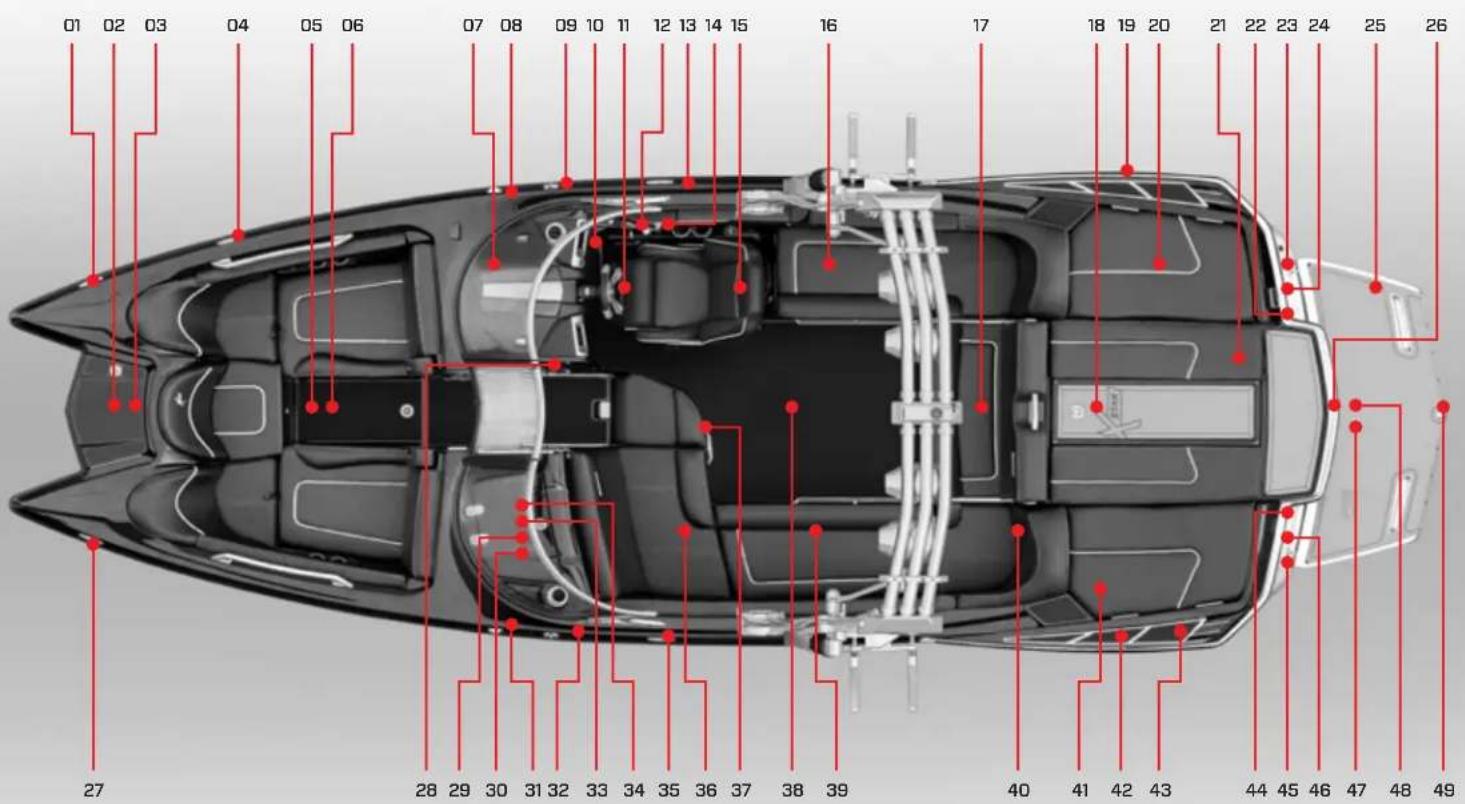
text_image
01 02 03 04 05 06 07 08 09 10 11 12 13 14 15 16 17 18 19 20 21 22 23 24 25 26 27 28 29 30 31 32 33 34 35 36 37 38 39 40 41 42 43 44 45 46 47 48 49FEATURES
- Bow cleat
- Anchor
- Ladder (where equipped)
- Horn
- Bow filler cushion (where equipped)
- KGB ballast tank (beneath floorboard)
- Circuit breaker panel (on kick panel beneath instrument panel)
- Nav/anchor light
- Fuel tank filler
- Instrument panel (details in Video Display Gauge section)
- Steering wheel
- Fire suppression unit manual override
- Midship cleat
- Shift/throttle control
- Heated seat (where equipped)
- Cooler (under seat)
- Stern light receptacle
- Engine compartment
- Stern cleat
port and starboard near transom) - Ballast tank
- Automatic fire extinguisher
- Shower (where equipped)
- Freshwater flush port (where equipped)
- Underwater lights (two, where equipped, under swim platform)
- Swim platform
-
Transom drain plug (center beneath swim platform)
-
Bow cleat
- Adjustable mirror
- Amp
- Hand-held fire extinguisher (inside)
- Nav/anchor light
- Fuel tank filler
- iPod interface (inside, where equipped)
- Glove box
- Midship cleat
- Observer seat (heated, where equipped)
- Jump seat
- Center drain plug (access plate under lid)
- Subwoofer
- Batteries (including ON-OFF switch)
- Ballast tank
- Stern cleat
- Blower exhaust (two, on top of port and starboard deck near transom)
- Stereo remote (where equipped)
- Freshwater tank fill
- Washdown connection (where equipped)
- Wake adjustment plate (under swim platform, where equipped)
- Transom rail with tow eye
- Under-platform ladder (where equipped)
SPECIFICATIONS
Length of Boat 24'0"
Width Amidship 102"
Boat Weight 5,400 lbs.
Length of Boat w/Platform 26'1"
Towing Length 29' 9"
Towing Width 102"
Fuel Capacity 74 gallons
Maximum Capacity 13 people or 1,852 lbs.
Bow: 5 people or 700 lbs.
Weight must be evenly distributed.
Storage space is located under:
Observer's seat, bow seating, aft and wrap-
around seating, port and starboard sun pads.
XSTAR
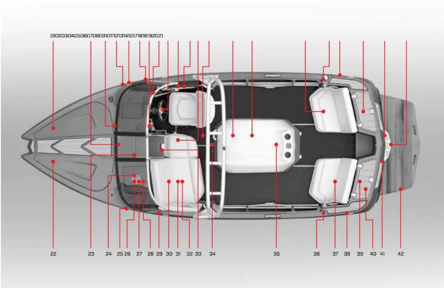
text_image
010203040506070809101112131415171816192021 22 23 24 25 26 27 28 29 30 31 32 33 34 35 36 37 38 39 40 41 42FEATURES
- Bow hatch (where equipped)
- Drop-in walk-thru door
- Circuit breaker panel, including battery ON-OFF switch (side panel, walk-thru)
- Bilge thru-hull outlet
- Navigation light
- Bow cleat (where equipped)
- Adjustable mirror
- Instrument panel (details follow) instrument panel)
- Steering wheel
- Shift-throttle control
- Fire suppression unit manual override
- Storage compartment
- In-floor storage compartment
- Center drain plug (inside engine compartment on deck floor)
- Engine compartment
- Aft seating (where equipped)
- Fuel tank filler
- Stern cleat (where equipped)
- Aft storage compartment
- Transom drain plug (center beneath swim platform)
- Transom rail with tow eye (where equipped)
- Bow seating (where equipped)
- Heater (where equipped)
- Sirius Satellite Radio (where equipped)
- Navigation light
-
Stereo CD Player (inside glove box, where equipped)
-
iPod interface (where equipped, inside glovebox)
- Glovebox
- Bow cleat (where equipped)
- MTS Ballast System (where equipped, beneath observer seat)
- Hand-held fire extinguishers (beneath observer seat)
- Amp (where equipped, beneath observer seat)
- Folding walk-thru seat
- Ski pylon
- Automatic fire extinguisher (inside engine compartment)
- Stern light receptacle (if equipped with tower, the light will be in center aft of tower)
- Aft seating (where equipped)
- Stern cleat (where equipped)
- Battery (beneath storage door)
- Aft storage compartment
- Engine exhaust (two below swim platform)
- Swim platform
SPECIFICATIONS
Length of Boat 20'0"
Width Amidship 96"
Boat Weight 3,300 lbs.
Length of Boat w/Platform 21' 6"
Towing Length 25' 11"
Towing Width 100"
Fuel Capacity 25 gallons
Maximum Capacity 7 people
or 1,341 lbs.
Bow: 2 people or 300 lbs.
Weight must be evenly distributed.
Storage space is located under:
Observer's seat, bow seating, aft and wrap-
around seating, port and starboard sun pads.
PROSTAR
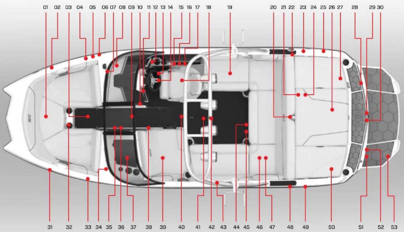
text_image
01 02 03 04 05 06 07 08 09 10 11 12 13 14 15 16 17 18 19 20 21 22 23 24 25 26 27 28 29 30 31 32 33 34 35 36 37 38 39 40 41 42 43 44 45 46 47 48 49 50 51 52 53FEATURES
- Anchor storage compartment
- Navigational light
- Access to forward bilge pump
- Bilge thru-hull
- Ballast thru-hull vent
- Cleat (where equipped)
- GPS antenna
- Circuit breaker panel (access under helm)
- Walk-thru door (where equipped)
- Mirror
- Stereo + iPod interface (on dash, where equipped)
- Instrument panel (see Video Screen and Switches information for details)
- Heater vent (on kick panel, where equipped)
- Tilt steering wheel
- Shifter/throttle control
- Emergency safety stop switch
- Fire suppression unit manual override
- Adjustable driver's seat
- Cooler (beneath seat)
- Ski pylon (where equipped)
- Sea strainer (where equipped)
- Fuel tank filler
- Bilge thru-hull vent
- Automatic fire extinguisher (inside engine compartment)
- Cleat (where equipped)
- Engine compartment
- Storage compartment + access to starboard side tsunami pump
-
Transom stereo remote (where equipped)
-
Attitude adjustment plate (where equipped, beneath swim platform)
- Transom drain plug
- Cleat (where equipped)
- Courtesy lights
- Sirius radio antenna (where equipped)
- Amp
- Ski locker + access to center tank tsunami pumps
- Heater vent (where equipped)
- Glove box
- Subwoofer (where equipped)
- Hand-held fire extinguisher (beneath observer seat)
- Center drain plug (accessible under carpet)
- Center ski pylon (where equipped)
- Tower tow rope attachment and light
- Tower (speakers, where equipped)
44.12-volt receptacle - Courtesy light
- Battery ON-OFF switch (where equipped)
- Battery(ies)
- Ballast thru-hull vent
- Cleat (where equipped)
- Storage compartment + access to port side tsunami pump
- NXT Wake Shaping devices (two devices, one on each side)
- Engine exhaust (two, one on each side beneath swim platform)
- Swim platform
SPECIFICATIONS
Length of Boat 20'0"
Width Amidship 91"
Boat Weight 3,950 lbs.
Length of Boat w/Platform 21' 8"
Towing Length 25' 7"
Towing Width 100"
Fuel Capacity 44 gallons
Maximum Capacity 11 people or 1804 lbs.
Bow: 4 people or 600 lbs.
Weight must be evenly distributed.
Storage space is located under:
Observer's seat, bow seating, aft and wraparound seating, port and starboard sun pads.

text_image
NXT20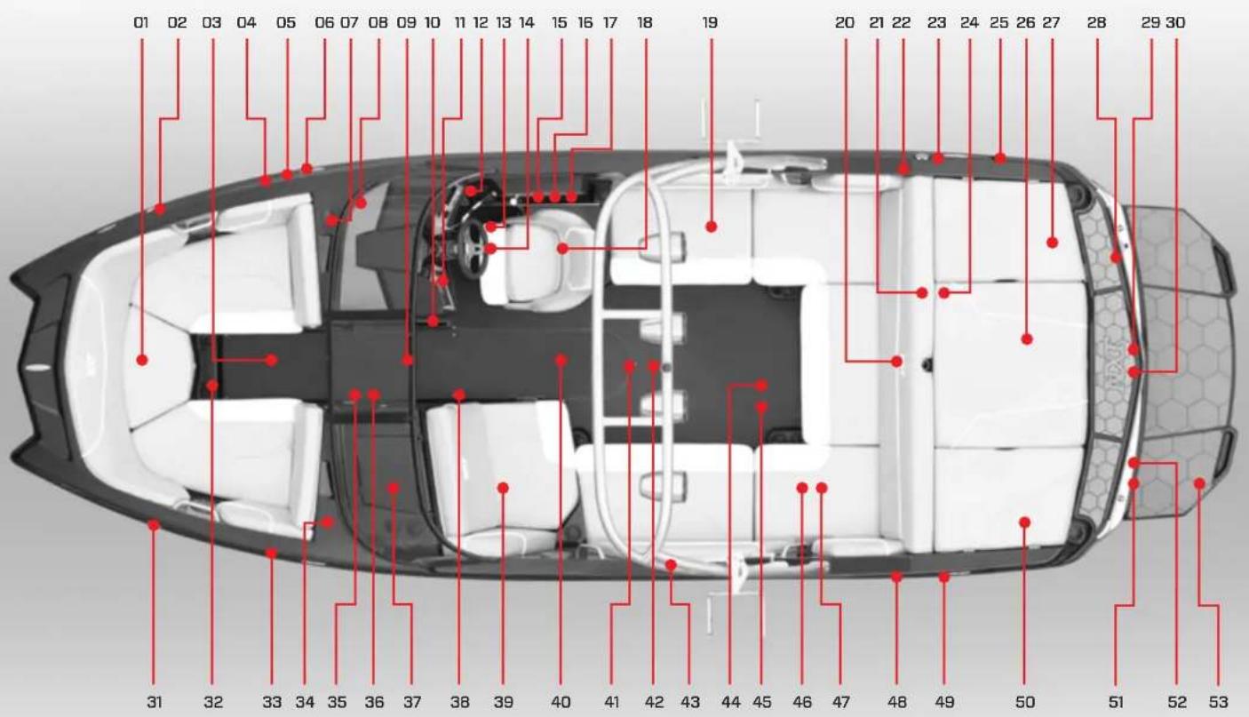
text_image
01 02 03 04 05 06 07 08 09 10 11 12 13 14 15 16 17 18 19 20 21 22 23 24 25 26 27 28 29 30 31 32 33 34 35 36 37 38 39 40 41 42 43 44 45 46 47 48 49 50 51 52 53FEATURES
- Anchor storage compartment
- Navigational light
- Access to forward bilge pump
- Bilge thru-hull
- Ballast thru-hull vent
- Cleat (where equipped)
- GPS antenna
- Circuit breaker panel (access under helm)
- Walk-thru door (where equipped)
- Mirror
- Stereo + iPod interface (on dash, where equipped)
- Instrument panel (see Video Screen and Switches information for details)
- Heater vent (on kick panel, where equipped)
- Tilt steering wheel
- Shifter/throttle control
- Emergency safety stop switch
- Fire suppression unit manual override
- Adjustable driver's seat
- Cooler (beneath seat)
- Ski pylon (where equipped)
- Sea strainer (where equipped)
- Fuel tank filler
- Bilge thru-hull vent
- Automatic fire extinguisher (inside engine compartment)
- Cleat (where equipped)
- Engine compartment
- Storage compartment + access to starboard side tsunami pump
-
Transom stereo remote (where equipped)
-
Attitude adjustment plate (where equipped, beneath swim platform)
- Transom drain plug
- Cleat (where equipped)
- Courtesy lights
- Sirius radio antenna (where equipped)
- Amp
- Ski locker + access to center tank tsunami pumps
- Heater vent (where equipped)
- Glove box
- Subwoofer (where equipped)
- Hand-held fire extinguisher (beneath observer seat)
- Center drain plug (accessible under carpet)
- Center ski pylon (where equipped)
- Tower tow rope attachment and light
- Tower (speakers, where equipped)
44.12-volt receptacle - Courtesy light
- Battery ON-OFF switch (where equipped)
- Battery(ies)
- Ballast thru-hull vent
- Cleat (where equipped)
- Storage compartment + access to port side tsunami pump
- NXT Wake Shaping devices (two devices, one on each side)
- Engine exhaust (two, one on each side beneath swim platform)
- Swim platform
SPECIFICATIONS
Length of Boat 22' 0"
Width Amidship 98"
Boat Weight 4,200 lbs.
Length of Boat w/Platform 23' 10"
Towing Length 27' 4"
Towing Width 102"
Fuel Capacity 50 gallons
Maximum Capacity 14 people
or 2,312 lbs.
Bow: 4 people or 600 lbs.
Weight must be evenly distributed.
Storage space is located under:
Observer's seat, bow seating, aft and wrap-
around seating, port and starboard sun pads.
NXT22
DASHES AND VIDEO SCREENS
$$ \frac{1}{2} = \frac{1}{2}\left( \frac{\ln x}{2} - \frac{\ln y}{2} \right) + \frac{1}{2}\left( \frac{\ln z}{2} - \frac{\ln x}{2} \right) + \frac{1}{2}\left( \frac{\ln z}{2} - \frac{\ln x}{2} \right) + \frac{1}{2}\left( \frac{\ln z}{2} - \frac{\ln x}{2} \right) + \frac{1}{2}\left( \frac{\ln z}{2} - \frac{\ln x}{2} \right) + \frac{x}{2}\left( \frac{\ln z}{2} - \frac{\ln x}{2} \right) + \frac{x}{2}\left( \frac{\ln z}{2} - \frac{\ln x}{2} \right) + \frac{x}{2}\left( \frac{\ln z}{2} - \frac{\ln x}{2} \right) + \frac{x}{2}\left( \frac{\ln z}{2}-\frac{x}{2} \right) + \frac{x}{2}\left( \frac{\ln z}{2}-\frac{x}{2} \right) + \frac{x}{2}\left( \frac{\ln z}{2}-\frac{x}{2} \right) + \frac{x}{2}\left( \frac{\ln z}{2}-\frac{x}{2} \right) + \frac{x}{2}\left( \frac{\ln z}{3}-\frac{x}{3} \right) + \frac{x}{3}\left( \frac{\ln z}{3}-\frac{x}{3} \right) + \frac{x}{3}\left( \frac{\ln z}{3}-\frac{x}{3} \right) + \frac{x}{3}\left( \frac{\ln z}{3}-\frac{x}{3} \right) + \frac{x}{3}\left( \frac{\ln z}{3}-\frac{x}{3} \right) + 0. \tag{1,1} $$
Immediately following this introduction are photo images of the five types of instrument panels utilized on MasterCraft boats. Operators should match up the appropriate image with the actual instrument panel on your boat.
All boats, except the XStar and the NXT series, have gauges that provide critical read-out information that is also provided through the video screen(s). All functionality on the XStar and NXT appears only in the video screens.
Explanations of the gauges appear after the instrument panel illustrations. The video screen operations are broken down into the XSeries information, which utilizes a standard 4.5" screen or an optional 7" screen, the XStar, which uses two (2) 4.5" screens and a 7" screen, the ProStar, which uses a 7" screen, and the NXT, which uses a 4.5" screen. MasterCraft encourages all boat owners to go over the gauge and/or video screen operations with your authorized MasterCraft dealer prior to operating the boat.

DANGER
Do not become distracted while utilizing multifunctional screens. Maintain situational awareness and do not change settings in crowded boating/swimming areas.
VARIATIONS IN GAUGES AND SWITCHES
Please note that not every gauge or switch explained in this Owner's Manual is found on every model. Some equipment is optional, and not every option is available on all models of MasterCraft boats.
Also, MasterCraft utilizes a variety of gauge and switch styles that may be different from the gauges or switches pictured in this Owner's Manual. These differences between the various styles of gauges and switches are not in functionality. If a boat is equipped with a gauge or switch that is labeled as described, it will operate in the same fashion as the description, even if its appearance is different, as the appearance changes periodically.
If the owner and/or operators are uncertain about the purpose of a gauge or switch, do not operate the boat until consulting with an authorized MasterCraft dealer. Some gauges monitor information that is critical to safe and long-term use of the boat. Some switches can affect maneuverability, as well as operations that impact long-term use of the boat.
XSTAR INSTRUMENT PANEL
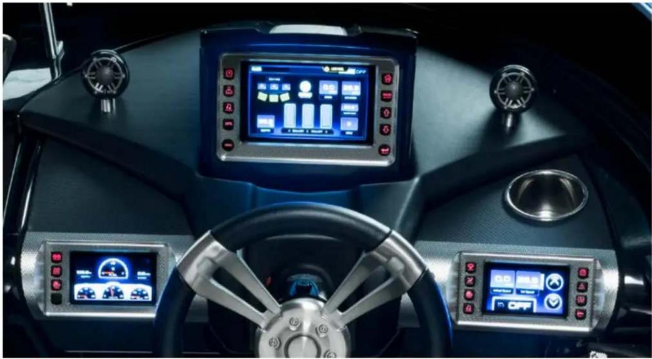
natural_image
Interior view of a vehicle dashboard with digital displays and steering wheel (no visible text or symbols)XSERIES INSTRUMENT PANEL: 7" VIDEO SCREEN
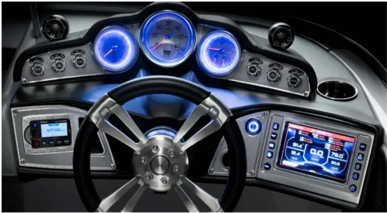
natural_image
Interior view of a modern sports car cockpit with digital gauges and steering wheel (no visible text or symbols)XSERIES INSTRUMENT PANEL: 4.3" VIDEO SCREEN
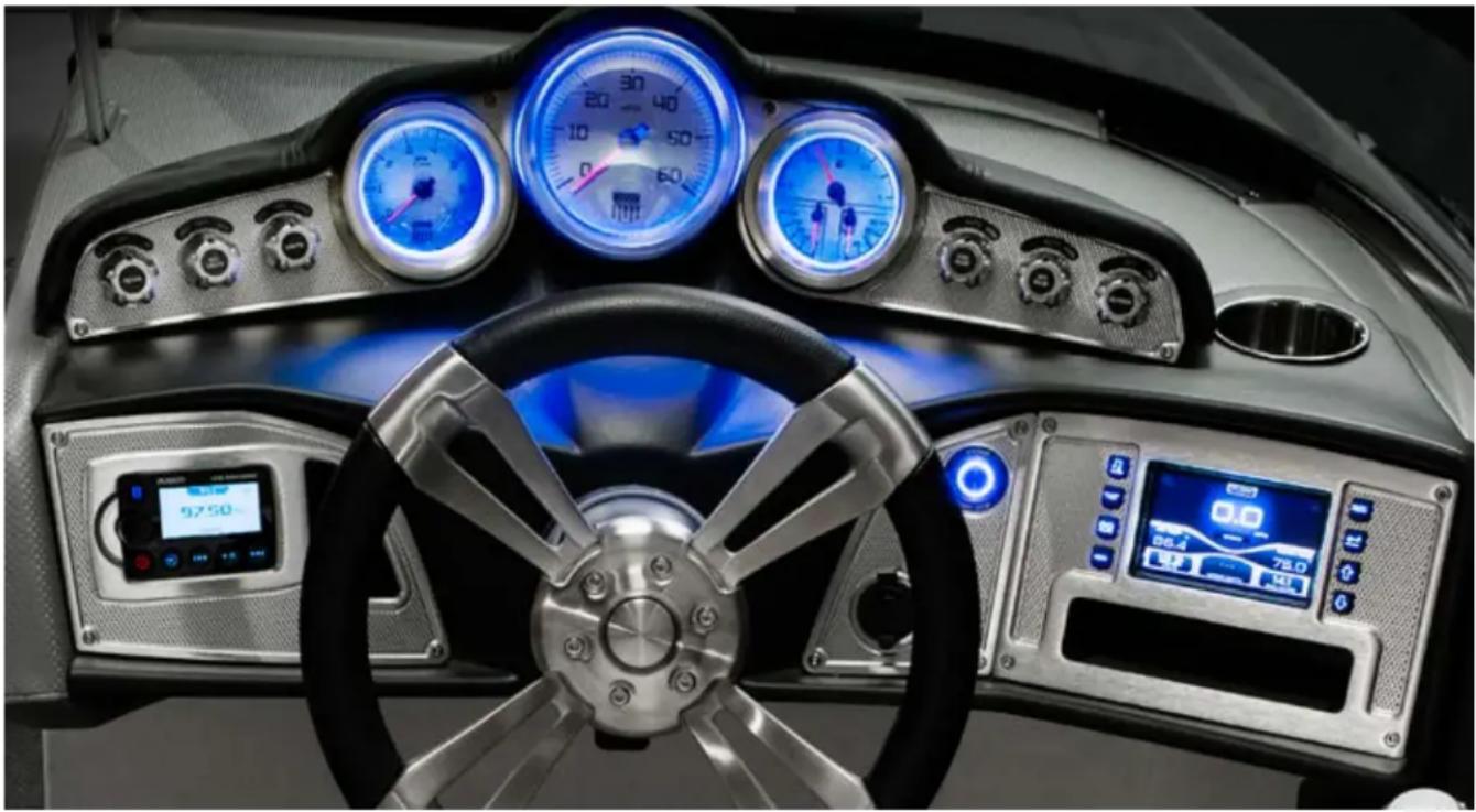
natural_image
Interior view of a modern car dashboard with blue-lit gauges, steering wheel, and digital displays (no readable text or symbols)PROSTAR INSTRUMENT PANEL
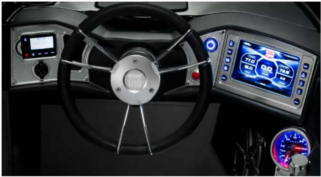
natural_image
Interior view of a ship's steering wheel and dashboard console (no visible text or symbols)NXT INSTRUMENT PANEL
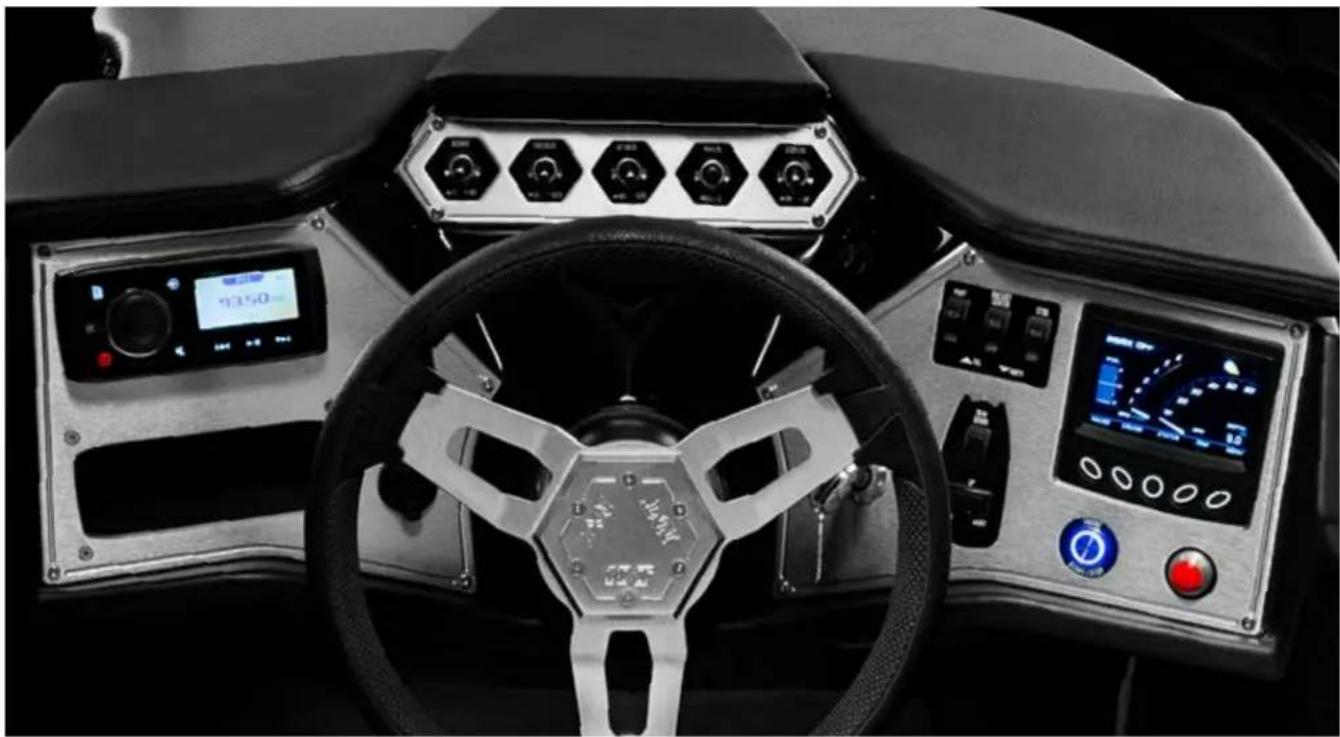
natural_image
Interior view of a vehicle's steering wheel and dashboard with digital displays (no readable text or symbols)XSERIES ENGINE GAUGES
This section discusses the performance controls. Information is provided via traditional gauges; however, it (as well as some convenience and support data described elsewhere in this Owner's Manual) is provided through a video screen located on the lower right (starboard) side of the instrument panel. Descriptions of the functionality of the video screen immediately follows.
MasterCraft strongly encourages you to review ALL instrumentation with your authorized MasterCraft dealer prior to operating the boat for the first time, and at any time during ownership you are uncertain as to proper and applicable functionality.
SPEEDOMETER
natural_image
Close-up of a circular gauge or dial with a red needle pointing to approximately 50 degrees (no visible text or symbols beyond the scale)The speedometer indicates the forward speed of the boat in miles per hour (unless the boat is equipped with a speedometer that measures kilometers per hour, which is available in the optional European package.)
TACHOMETER
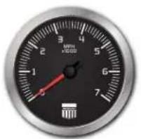
natural_image
Close-up of a black industrial gauge with red needle and scale markings (no readable text or symbols)The tachometer indicates the engine speed in crankshaft revolutions per minute (RPM). See the Engine section of this Owner's Manual for important information regarding proper operating RPM levels, particularly during a boat break-in period.
3-IN-1 GAUGE: FUEL GAUGE
Upper Half of Gauge
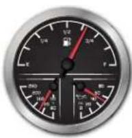
Fuel gauge readings are approximate. This gauge is activated with the ignition switch. The rocking motion of the boat during normal operation will cause the fuel gauge to fluctuate. For a more accurate reading, make sure that the boat is level and there is little or no motion present.
A "low fuel" notice will come up on the video screen as a warning to return to shore and refuel. MasterCraft recommends that operators do not run the boat below a quarter of a tank, except as necessary to return to shore, and not until the boat has been operated enough times to develop an understanding of how the fuel gauge readings relate to the visual inspection of fuel remaining in the tank. Extending fuel usage beyond the known capability of the boat may cause the boat to run out of fuel and may leave you stranded off-shore.
Although it may be possible to see fuel in the bottom of the fuel tank, you still may not be able to operate the boat. The fuel pick-up system was designed to avoid introducing the small amount of water and debris that unavoidably accumulate in the bottom of the tank. Rather than relying on visual inspection, you should pay attention to the fuel gauge.
Further, it is not recommended to allow the fuel to fall below one-quarter of a tank full at any time as it may result in damage to the fueling system. (See the Fueling section of this Owner's Manual.)

CAUTION
Allowing the fuel level in the fuel tank to fall below one-quarter of a tank full may affect the reliability of the fuel pump or result in damage to the fuel pump, which is not covered under warranty.
3-IN-1 ENGINE OIL PRESSURE GAUGE
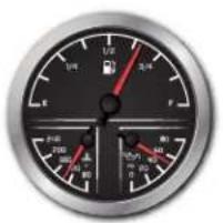
text_image
Close-up of a dial indicator with Chinese numerals and red needle pointing to 1/2, showing measurement ranges.Lower Right Side
The engine oil pressure gauge indicates the pressure of the lubricating oil inside the engine. The average pressure ranges are between six (6) pounds per square inch (PSI) at 1000 RPM to 40 PSI or more at cruise-range speeds. A reading of pressure
below 5 PSI at 1000 RPM may be caused by a low oil level or other potentially serious problems that result in low oil pressure, causing a red warning light to appear at the bottom of the gauge.
If you experience low oil pressure, stop your engine immediately and check your oil level before operating again.

CAUTION
Do not continue to run the engine if the oil pressure is low. If you do, the engine may become so hot that it, or surrounding components, could catch fire. You or others could be burned and the boat seriously damaged. Check your oil level and add an appropriate amount of approved motor oil before operating again or have your boat serviced by your local authorized dealer's service department. Note that damage to your engine from inappropriate oil levels can be costly to repair. Such damage is not covered by your warranty.
3-IN-1 WATER TEMPERATURE GAUGE
Lower Left Side
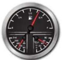
The temperature gauge indicates the water temperature inside the engine's cooling system as measured in degrees Fahrenheit. The normal operating temperature will range from 140 degrees Fahrenheit to 190 degrees Fahrenheit. Engines with electronic fuel injection also have a control circuit inside the
engine control module that will cause the engine to run at reduced speeds if the module senses that the engine is running too hot. If you notice that your speed has reduced during normal operation, but you have not manually slowed the throttle, monitor your temperature gauge.
If the gauge indicates excessive temperatures during operation, slow down immediately and turn off the engine. This indicates an engine problem that needs to be checked by the dealer!

CAUTION
Continuing to operate the boat while the temperature is above normal operating parameters may cause serious damage to your engine. Damage to your engine resulting from operating the engine in an overheated condition can be costly to repair. Such damage is not covered by your warranty!
The X-Series is designed for instrumentation and control on electronically controlled engines communicating via SAF J1939 and NMEA 2000. The multimedia displays provide cruise control and rider profiles, and enable boat operators to view many different engine, ballest, transmission parameters and service codes. Included with this solution is the HV700 Touch unit.
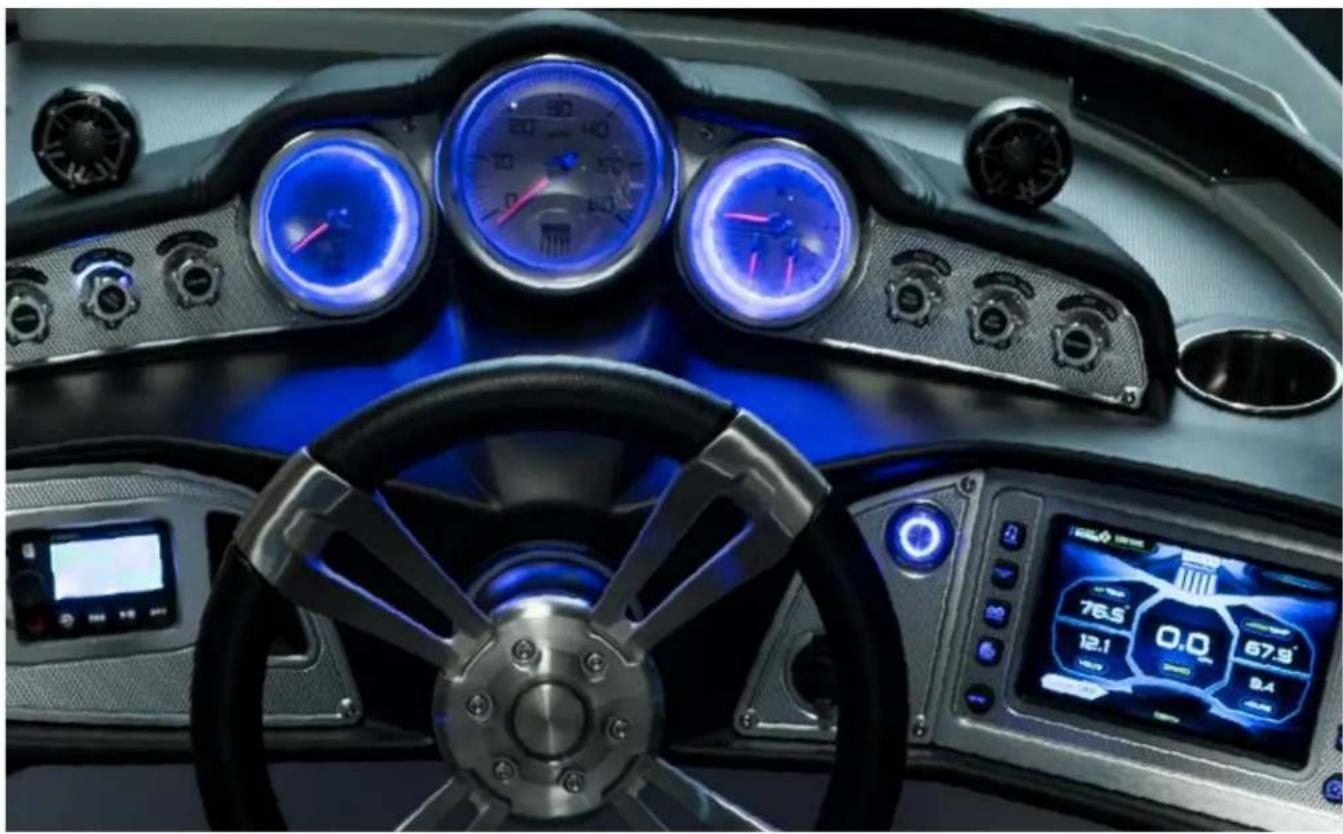
natural_image
Interior view of a futuristic sports car cockpit with illuminated dashboard, speedometer, and digital displays (no readable text or symbols)
text_image
MasterCraftThe X-Series is designed for instrumentation and control on electronically controlled engines communicating via SAE J1939 and NMEA 2000. The multimedia displays provide cruise control and rider profiles and enable boat operators to view many different engine, ballast, transmission parameters and service codes. Included with this solution is the HV700 Touch unit.
CARE AND MAINTENANCE
General maintenance is not required; however, a soft cloth can be used for cleaning the unit. Window cleaner or alcohol can also be used to clean the glass portion of the display. Do not use harsh or abrasive cleaners on the unit.

CAUTION
Avoid contact between sharp or hard objects and the video touch screen because this can result in scratches or other permanent marks on the screen. Clean only with a soft cloth, using window cleaner or rubbing alcohol only. Never use harsh or abrasive cleaners on the unit, as this may result in damage to the unit that is not covered under warranty.
BASIC NAVIGATION FEATURES
All product features are easily accessed through Quick Access Keys, Touch Commands and Menus.
QUICK ACCESS KEYS
The following screens can be accessed quickly by pressing a Quick Access Key: Audio, Ballast/Trim, Gauges, Video, Settings Menu, Navigation, User Profiles and Cruise.
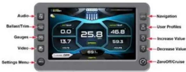
text_image
Audio Ballast/Trim Gauges Video Settings Menu Navigation User Profiles Increase Value Decrease Value ZeroOff/CruiseTOUCH COMMANDS
Once the desired screen is accessed, navigation within the screen is controlled with Touch Commands. They are executed by touching the screen in areas that are outlined with a highlighted bezel.
In addition, there are areas where sliding your finger up or down can adjust the settings. For example, on the Ballast and Trim screen, sliding your finger up on the inside of the tank area adjusts the ballast setting.
There are also areas where swiping your finger from side to side will scroll through a list.
When the slider bar on top of the screen is visible, sliding your finger across it will change screens.
NOTE: While the slide area might appear to be curved, it is really a straight line.
AUDIO
The Audio screen can be accessed by pressing the Audio Quick Access Key on the HV700. Press any Quick Access Key to exit this screen.
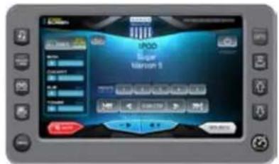
text_image
iPOD Super Version 1| Audio Touch Command | Description |
 | Power - Turns stereo system on/off. |
 | Volume - Touch this button to lower the volume. |
 | Volume - Touch this button to raise the volume. |
 | Mute - Touch this button to mute the volume. |
 | Next Track - Plays the previous track current CD. |
 | Next Track - Plays the next track of the current CD. |
 | Rewind - Touch this button to rewind the current selection. |
 | Fast Forward - Touch this button to fast forward the current selection. |
| Audio Touch Command | Description |
 | Scan/Stop - Enables and stops the scanning of available channels. |
 | Stereo Setting - Displays the following settings screen: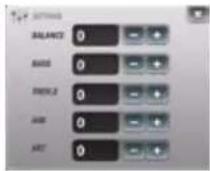 Utilize the + and - buttons to adjust the settings. Utilize the + and - buttons to adjust the settings. |
  | iPod Menu - Touch this button to display the iPod menu, as shown below: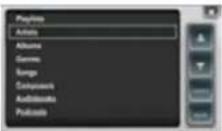 Utilize the Up and Down arrows, then touch Select when the appropriate choice is displayed.Source - Touch this to select a connected source. MasterCraft supports the following devices:FM radioAM radioSatiPod/USBDVDVHFSirius XM RadioAuxiliaryRegional Weather Channel Utilize the Up and Down arrows, then touch Select when the appropriate choice is displayed.Source - Touch this to select a connected source. MasterCraft supports the following devices:FM radioAM radioSatiPod/USBDVDVHFSirius XM RadioAuxiliaryRegional Weather Channel |
 | Zone Volume - Control the volume in the four zones of the boat by sliding your finger to the right or left on each line.Utilize the Up and Down arrows, then touch Select when the appropriate choice is displayed. |
BALLAST AND TRIM
The Ballast and Trim screen can be accessed by pressing the Ballast/Trim Quick Access Key on the HV700. Press any Quick Access Key to exit this screen. This screen displays the current state of the ballasts and trim tabs.
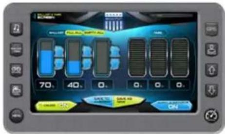
text_image
70, 40, 0, 0, 0, 0 SAP-12 SAP-13 ONNOTE: This example shows three Ballasts on the Ballasts screen. Your dealer sets this option at 0, 1, 2 or 3 ballasts to fit your boat package.
| Ballast and Trim Touch Command | Descriptions |
 | Touch to turn cruise control OFF or ON. |
 | Non-interactive graphic that displays a changing of the screens. |
| Touch to stop all activity on this screen. | |
 | Touch to turn AUTO LAUNCH/EXIT ON or OFF. When Auto Launch is on, it automatically controls the center tab. When speed is above the Auto Launch speed, the center tab will be retracted to 0%, or if a profile is selected, it deploys the center tab to the profile setting. If the speed is above the Auto Launch speed and then decelerated below the Auto Launch speed, the tab deploys to 100 (crossover speed). |
 | Touch to save the settings to the current rider profile.NOTE: If no rider profile is selected, this does nothing. |
| Ballast and Trim Touch Command | Descriptions |
 | Touch to save these settings to a new rider profile. A keyboard is displayed to name the new profile, and the new profile process is launched. (See the Profiles section starting on page 10.) |
 | Touch to fill all ballasts. |
 | Touch to empty all ballasts. |
 | Touch and slide your finger to the desired Ballast Tank level, or touch the UP/DOWN Arrows to obtain the level. |
 | Touch and slide your finger to the desired Trim Tab position. |
GAUGES
The Gauge screen can be accessed by pressing the Gauges. Quick Access Key on the HV700. Press any Quick Access Key to exit this screen.
| Gauge Information | |
| Speedometer (MPH) Water Depth (FT) | |
| Air Temperature (F°) Water Temperature (F°) | |
| Battery Voltage (Volts) Engine Run Time (Hours) |
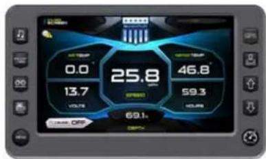
other
| Metric | Value | | :--- | :--- | | Speed | 25.8 | | Volume | 13.7 | | Efficiency | 46.8 | | Speed (kW) | 59.3 | | Efficiency (%) | 69.1 | Level: OFF| Gauge Touch Commands | Description/Action |
 | Touch to turn cruise control ON or OFF. |
| Non-interactive graphic that displays a changing of the screens. |
VIDEO
The Video screen can be accessed by pressing the Video Quick Access Key on the HV700. Press any Quick Access Key to exit this screen.
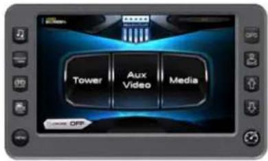
text_image
Tower Aux Video Media OFF| Video Touch Commands | Description/Action | |
 | Touch to turn cruise control ON or OFF. | |
| Non-interactive graphic that displays a changing of the screens. | ||
 | Touch to view the Tower video source.Press the Quick Access Key to go back. | |
 | Touch to view the Aux Video source.Press the Quick Access Key to go back. | |
 | Touch to view the Media video source.Press the Quick Access Key to go back. | |
| Video Touch Commands | Description/Action |
 | Touch to view the Aux Video source.Press the Quick Access Key to go back. |
 | Touch to view the Media video source.Press the Quick Access Key to go back. |
GPS/NAVIGATION
The GPS/Navigation screen can be accessed by pressing the GPS Quick Access Key on the HV700. Press any Quick Access Key to exit this screen
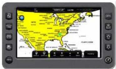
text_image
Screenshot of a tablet displaying a world map with geographic labels and navigation buttons| GPS Touch Commands | Description/Action |
| North Up / Course Up | Displays the map as having either north or the current direction headed at the top. |
| Zoom In Touch to zoom in on the cursor location. | |
| Zoom Out Touch to zoom out on the cursor location. | |
| Left Touch this to move the cursor to the left on the map. | |
| Right Touch to move the cursor to the right on the map. | |
| Up Touch to move the cursor up on the map. | |
| Down Touch to move the cursor down on the map. | |
| Tracking (Zoom/Pan) | Provides four commands and displays the Zoom/Pan command to switch back. |
| Current Position Return to the current boat/satellite position after moving the cursor to another location. | |
| Create Waypoint Places a marker or waypoint on the map to mark a favorite location after displaying a keyboard to name the waypoint. | |
| Clear Track Displays message before a confirmation deleting the current track information. | |
| Save Track Displays a confirmation message before saving the current track information. | |
PROFILES
The Profiles screen can be accessed by pressing the Profile Quick Access Key on the HV700.

This feature displays rider/user profiles for cruise control based on user preferences for Set Speed, Ballast and Tab settings. Up to 16 rider/user profiles can be created and stored.
To scroll through the available Profiles, slide finger across the information slide bar. Salon Town: a Quick Access Keys and view the list.
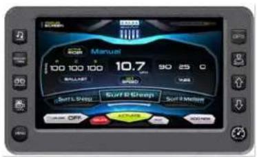
text_image
Manuel 100 100 100 10.7 90 25 C BALANCE OFF Surf & Smooth Surf Meter OFF OFF AUTO ONIONNew User Profile
A new rider profile can be set-up using the HV700 Touch. To create a new profile, press the Profile Quick Access Key.
| New User Profile Display Instructions | |
 | Touch [Add New] to create a new profile. |
 | Type a name for the new profile using the touch keypad, and touch [Done]. |
 | Touch [Next] to continue. |
| New User Profile Display Instructions | |
 | Touch the [Up] or the [Down] arrow to Set the speed for this profile. Touch [Next] to continue. |
 | Set the tabs by either sliding your finger on the ridged area or by touching the [Up] and [Down] arrows. Touch [Next] to continue. |
 | Set the ballast tanks by touching and sliding your finger up the tank area or by touching the [Up] and [Down] arrows alongside the tank area. Touch [Next] to continue. |
 | On the Save screen, review the Profile settings. Touch [Save] to save the profile and return to the Profiles screen with the new profile displayed (continued on next page) |
New User Profile Display Instructions

text_image
4.0 70 60 50 FLAVETARThe new rider's name is listed above the Activate Touch Command. Touch [Activate] to activate the rider settings.
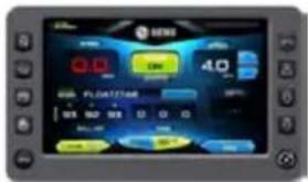
text_image
0.0 4.0 PLOT2768 0.0 0.0 0.0 0.0 0.0 0.0 0.0 0.0The GEN2 Surf System screen will appear with the new profile activated. From this screen, you can turn On/Off Cruise; set the preferred speed for the profile; deactivate the current profile; turn on/off the Auto Launch/Exit; save the settings to the current profile; and save the settings to a new profile.
Delete Current Profile
A rider profile can be deleted using the HV700 Touch. To delete a new profile, press the Profile Click Access Key.
Delete Current Profile Display Instructions
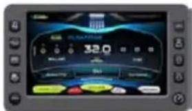
text_image
32.0 OFFICE SINEMA SINEMASlide finger across the slide bar to position the rider's profile name in the highlighted position. Touch [Delete] to delete the current profile.
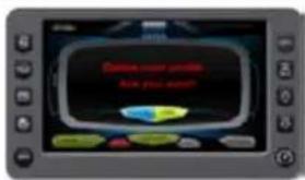
text_image
Online user profile Have you own!A confirmation overlay is displayed. Touch [Cancel] to abort the process and [Yes] to confirm delete.
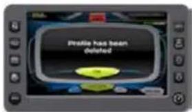
text_image
Freddie has been deletedProfile has been deleted will appear. Touch [OK] to return to the Profiles screen. The rider will no longer be listed in the slide bar.
Edit Current User
A rider profile can be edited using the HV700 Touch. To edit a new profile, press the Profile Tick Access Key.
| Delete Current Profile Display Instructions | |
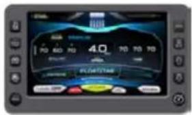 | Slide finger across the slide bar to position the rider's profile name in the highlighted position. Touch [Delete] to delete the current profile. |
 | Touch [Edit] to retype the name. Touch [Next] to continue or [Cancel] to return to the Profiles screen. |
Follow the same steps as creating a new profile.
Touch [Next] to continue to the next screen without change. Remember to click [Save] on the final screen to save the changes.
Cruise
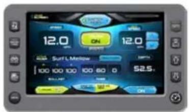
text_image
12.0 ON 12.0 Surf L Mellow 100 100 100 100 60 0 52.5. ON ONPressing the Cruise Quick Access Key displays the above screen. The button displays these four preset Rider profiles:
- Surf L (Left) Mellow
- Surf L (Left) Steep
- Surf R (Right) Mellow
- Surf R (Right) Steep
If the preset settings need adjusting, touch the button and make the appropriate changes. Pressing Save to Current will change the existing profile. Pressing Save As New will provide a keyboard to name the new profile. Ensure the new profile is Activated prior to the beginning of the surfer's ride.
To turn On/Off Cruise, touch the

The button automatically deploys or retracts the center tab to aid in getting the boat on or off plane.
SETTINGS MENU

Access the Settings Menu screen by pressing the Menu Quick Access Key on the HV700. The following settings are available:
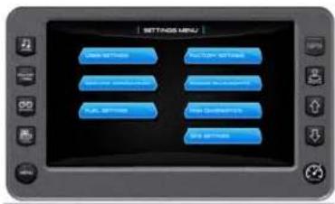
text_image
SETTINGS MENU Close to Inside Active/Down Off/Cancel Sequence Options Close to Next/Next Full Options Main Options Main Options| Settings Menu Touch Commands | Description |
| User Settings — allows you to customize the display options for ambient light and brightness, set US or metric units, Tab, Ballast and other settings. | |
| Service Information — provides information about the software version, dealer, oil changes and dealer services. | |
| Fuel Settings — displays a method to enter the fuel gallons added and determine the added value. | |
| Factory Settings — displays boat model, center tab, surf tabs and depth transducer. A dealer code is required to access. | |
| Engine Diagnostics — displays Engine Diagnostics including a list of fault codes and descriptions, stored faults and corrective actions. On some screens, corrective action will be shown. | |
| PDM Diagnostics — displays the Power Distribution Module Diagnostics screen. | |
| GPS Settings — displays the facilities to manage Waypoints, Tracks, Charts & Times and Depth & Positions. Satellite status will also be shown for detectable satellites. NOTE: This option will only appear if a map card is installed. |
User Settings
On the Settings Menu screen, touch the
Touch
Command to access the first of two user settings screens. Touch the field following the option to change the setting. When arrows are available, touch the option to highlight it, then touch the arrows to change the setting.
Touch [Next] to access the second screen and [Back] to return.
text_image
Digital display screen showing a control panel with buttons and status indicators in Chinese
text_image
LAWB SETTINGS Size Brightness: 100 High Brightness: 4 Size Brightness - Size: 100 Size Brightness - High: 20 Fan Settings: Default Settings| User Settings Touch Commands | Description of Options |
| Units US Standard (US Std) | or Metric |
| Fire Extinguisher Enable or Disable | |
| Auto Volume Sets the level of the automatic volume | |
| Fuel Alarm Sets the percent of fuel left in tank to deploy the alarm | |
| Depth Alarm ON or OFF |
| User Settings Touch Commands | Description of Options |
| Day Brightness Sets the screen brightness for daylight | |
| Night Brightness Sets the screen brightness for nighttime | |
| Gauge Brightness - Day Sets the gauge brightness for daylight | |
| Gauge Brightness - Night Sets the gauge brightness for nighttime | |
| Tab Settings Page Controls the tab positions for the Center and Surf tabs on the boat (See Tab Settings) | |
| Ballast Settings Page Controls the ballast fill and drain times (See Ballast Settings) |
Tab Settings
On the User Settings screen, touch the Tab Settings Touch Command to access the Tab Settings screen. This provides the user with the opportunity to control the tab positions for the trim tabs on the boat. The following crossover speeds can be controlled through these settings:
- Center Tab
- Surf Tabs
text_image
TOM BEETTES CROSSER SPEED Speed: 16.0 m/s Bar Speed: 16.0 m/sBallast Settings (Tank Fill/Drain Times)
In the User Settings screen, touch the Ballast Settings Command to access the Ballast Settings screen. This screen provides the ability to control the ballast fill and drain times. Touch the ▼→□→□→□→□→□→□→□→□→□→□→□→□→□→□→□→□→□→□→□→□→□→□→□→□→□→□→□→□→□→□→□→□→□→□→□→□→□→□→□→□→□→□→□→□→□→□→□→□→□→□→ ^1 ▼→□→□→□→□→□→□→□→□→□→□→□→□→□→□→□→□→□→□→□→□→□→□→□→□→□→□→□→□→□→□→□→□→□→□→□→□→□→□→□→□→□→□→□→□→□→□→□→□→ ^ ▼→ ^ ▼→ ^ ▼→ ^ ▼→ ^ ▼→ ^ ▼→ ^ ▼→ ^ ▼→ ^ ▼→ ^ ▼→ ^ ▼→ ^ ▼
text_image
TANK FILL TIMES PILL TIMES P: 00 C: 00 S: 00 DRAIN TIMES NEXT OFF OKService Information
On the Settings Menu, touch the Touch Command to access the Service Information that allows the dealer to reset the engine oil change intervals and the dealer service schedule. NOTE: The Dealer Service Reset requires a dealer code to enter.
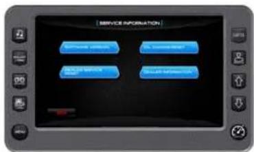
text_image
SERVICE INFORMATION Software Service Customer Support Order Service Order Information| Service Information Touch Commands | Description |
| Displays part numbers and versions for the application, software, operating system and more. | |
| The dealer sets the number of engine running hours between servicing intervals at which time an alert will be display. | |
| Touch to reset for the next oil change alert. (The service intervals are predetermined and set by the dealer.) | |
| Displays your dealer's contact information. |
Fuel Settings
The Fuel Settings screen provides a method to which the fuel can be monitored. Upon adding fuel to the boat, access this screen and enter the number of gallons added, or select Full if the tank has been filled.
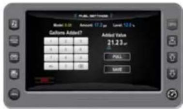
text_image
Model 3.01 Amount 17.2 μm Level 12.6 s Customs Added? Added Value 21.23 μm PULL SAVEClick Save and the following screen will appear:
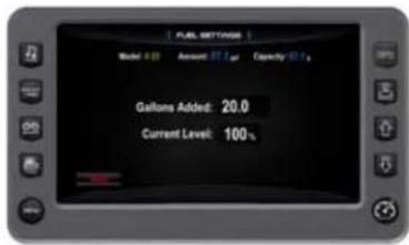
text_image
FUEL SETTINGS Model: 80 Amount: $7.5 Capacity: 50 % Gallons Added: 20.0 Current Level: 100 %When the unit first turns on, it boots up to the following screen:
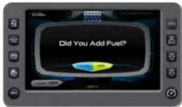
text_image
Did You Add Fuel?Clicking Yes will display the Fuel Settings screen shown above, and Cancel will display the Gauges screen.
Factory Settings
On the Settings Menu screen, touch the Touch Settings Command to access the Factory Settings screen. A Dealer code is required to access this screen.
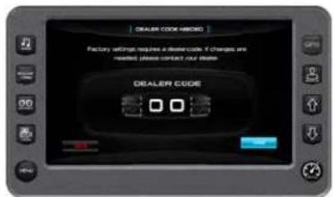
text_image
DEALER CODE HERO Factory settings require a dealer code. If changes are needed, please contact our dealer. DEALER CODEOnce the appropriate code is entered, click Done. The following screen will appear:
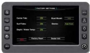
text_image
FACTORY SETTINGS Corner Tab: ON Boat Model: 1.0 Surf Tab: ON Stereo: Top Cover Depth / Water Temp: ON Factory Reset Dealer InfoFactory Reset will reset all the parameters that have been changed since the factory set them. Dealer Info will allow the editing of the address, phone, etc. of the boat dealer.
Engine Diagnostics
On the Diagnostics Menu screen, touch the Engine Diagnostics Touch Command to access the Engine Diagnostics screen.
text_image
ENGINE DIAGNOSTICS Aircraft Passes 1.0 Passes 2 Passes 3 Aircraft 4 Passes 5 Aircraft 6 Passes 7 Aircraft 8 Passes 9 Aircraft 10 Passes 11 Aircraft 12 Passes 13 Aircraft 14 Passes 15 Aircraft 16 Passes 17 Aircraft 18 Passes 19 Aircraft 20 Passes 21 Aircraft 22 Passes 23 Aircraft 24 Passes 25 Aircraft 26 Passes 27 Aircraft 28 Passes 29 Aircraft 30 Passes 31 Aircraft 32 Passes 33 Aircraft 34 Passes 35 Aircraft 36 Passes 37 Aircraft 38 Passes 39 Aircraft 40 Passes 41 Aircraft 42 Passes 43 Aircraft 44 Passes 45 Aircraft 46 Passes 47 Aircraft 48 Passes 49 Aircraft 50 Passes 51 Aircraft 52 Passes 53 Aircraft 54 Passes 55 Aircraft 56 Passes 57 Aircraft 58 Passes 59 Aircraft 60 Passes 61 Aircraft 62 Passes 63 Aircraft 64 Passes 65 Aircraft 66 Passes 67 Aircraft 68 Passes 69 Aircraft 70 Passes 71 Aircraft 72 Passes 73 Aircraft 74 Passes 75 Aircraft 76 Passes 77 Aircraft 78 Passes 79 Aircraft 80 Passes 81 Aircraft 82 Passes 83 Aircraft 84 Passes 85 Aircraft 86 Passes 87 Aircraft 88 Passes 89 Aircraft 90 Passes 91 Aircraft 92 Passes 93 Aircraft 94 Passes 95 Aircraft 96 Passes 97 Aircraft 98 Passes 99 Aircraft 100Field definitions on the Engine Diagnostics screen:
Active Faults/Stored Faults
Shows the number of active faults and which fault number is currently being displayed. To advance to the next fault, touch [NEXT]. Touch [PREV] to go back to the previous fault. Touching [BACK] returns to the Settings Menu.
SPN — Suspect Parameter Number — fault code. If not translated into text by the display, see the engine manufacturer's literature for the definition of the SPN number.
FMI — Failure Mode Indicator — fault code. The FMI is defined by SAE J1939. If not translated into text, see the SAE standard, or the engine manufacturer's literature.
Description Field — Most common SPNs and FMIs have text for the description stored in the display. If there is no text, then this SPN and FMI must be defined by referring to the engine manufacturer or the SAE J1939 standard.
NOTE: This field is only used with certain brands and models of engines.
Corrective Action
This shows the suggested action for correction of the faults.
Get Faults
Touching [Get Faults] queries the engine(s) ECU for feedback on diagnostic codes activated and stored in the ECU for service needs.
PDM Diagnostics
On the Diagnostics Menu screen, touch the Touch Command to access the PDM 1 Diagnostics screen.
text_image
PUM 1 DIAGNUTTER OUTPUTS INPUTS OUTPUTS CAN COMMUNICATION START VALUE OK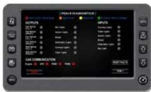
text_image
PANE & DISHIBERTS OUTPUTS 100 V 200 V 300 V 400 V 500 V 600 V 700 V 800 V 900 V 1000 V OUTPUTS INPUTS CAN COMMUNICATION SNOW: 200 MHz RAN: 200 MHz RAN: 200 MHz RAN: 200 MHz RAN: 200 MHz RAN: 200 MHz RAN: 200 MHz RAN: 200 MHz RAN: 200 MHz RAN: 200 MHz RAN: 200 MHz RAN: 200 MHz RAN: RAN:This screen displays any faults that have occurred for the Outputs, Inputs and/or CAN Communication.
Faults are color coded as follows:
• Red (Short Circuit or Out of Range)
- Orange (Open Circuit)
- Yellow (Over-Current)
• Green (No Faults / Active / In Range)
To reset existing faults, touch.
To display the alternate PDM Diagnostics screen, touch
GPS Settings
NOTE: This option will only appear if a map card is installed.
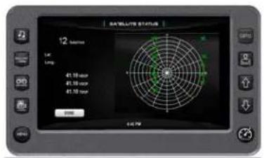
text_image
SATellite Status 12 seconds Lat: Long: 41.10 sec 41.10 sec 41.10 sec 0.000 0.079Waypoint Manager
Waypoints allow you to mark specific locations by latitude and longitude. Once the waypoints are established, the Waypoint Manager allows you to associate an icon with them for identification. You can delete a single waypoint by using the DELETE key or all of them at once with DELETE ALL. Pressing the GO TO ... key displays the GPS screen containing the currently highlighted waypoint.
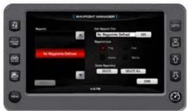
text_image
WA-POUNT MANAGER Name: No Significant Info No Significant Defined: 200 Reconciliation: This is No Significant Defined No Significant Defined 0.0173 0.0173-0.0173 OK 4:0:50Track Manager
Multiple tracks for displaying on the GPS map can be established. The Track Manager allows you to select tracks to show on the map or hide a map not currently used. You can DELETE one track or DELETE ALL at the same time.
Touch DONE when finished.
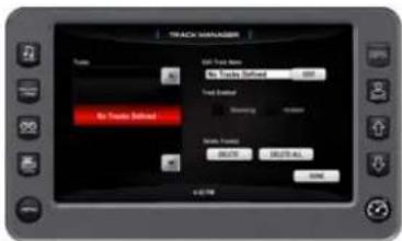
text_image
TRACK MANAGER Track Name: No Track Defined 600 Speed Based: Blending Window No Track Defined Status Based: 50.0% 100.0%-45% OKChart / Time Setup
This menu option allows you to set up viewing options for the GPS Display.
Chart Set-up Parameters
Touch to select the information you want displayed on the GPS screen.
Time Set-up Parameters
Used to select correct time zone and clock mode for either 12-hour or 24-hour time formats. You can also enable DST (Daylight Saving Time) by touching that box. Set the GMT Offset time (in hours) by repeatedly touching that selection until the appropriate number is shown. Touch DONE when finished.
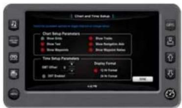
text_image
Chart and Time Setup Chart Setup Parameters Show Girls Show Tree Show Respondents Show Tools Show Navigation Mode Show Response Mode Time Setup Parameters GPT Other GPT Addition Display Format 12x Format 30x Format OKGPS Status
This option shows the location of discoverable satellites. Touch DONE when finished.
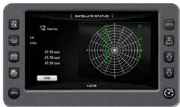
text_image
SATELLITE STATUS 12 Lift Long 41.10 Vcc 41.15 Vcc 41.15 Vcc 3000 4:27hDepth / Position Setup
This feature allows you to define the amount of detail to display for longitude and latitude information on the GPS map and depth display. Touch DONE when finished.
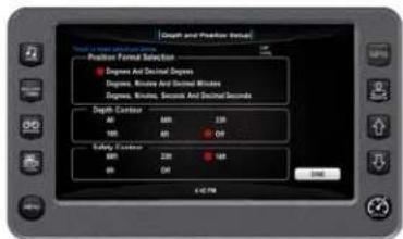
text_image
Depth and Practice Detail Position Forest Selection Degrees And Decimal Degrees Degrees, Minutes And Decimal Minutes Degrees, Minutes, Seconds And Decimal Seconds Depth Curator A0 A0 A0 200 B0 B0 B0 C0 B0 B0 B0 B0 B0 B0 B0 B0 B0 B0 B0 B0 B0 B0 B0 B0 B0 B0 B0 B0 B0 B0 B0 B0 B0 B0 B0 B0 B0 B0 B0 B0 B0 B1TROUBLESHOOTING
Display appears not to work or doesn't come ON.
- Display could be in sleep mode. Touch a key on the keypad to activate the display.
- Check for loose connections at battery and display unit.
- Check for reversed polarity on the power connections.
- Verify battery has a minimum voltage of 6 volts.
Display resets or goes OFF when starting engine.
- Check display supply wires are connected properly to battery.
- Verify battery is charged properly.
- Check battery for efficient starter current.
Display has no back light.
Contact your MasterCraft service center.
Display has no keypad back light.
Contact your MasterCraft service center.
XSERIES
VIDEO SCREEN
OPERATIONS HV450
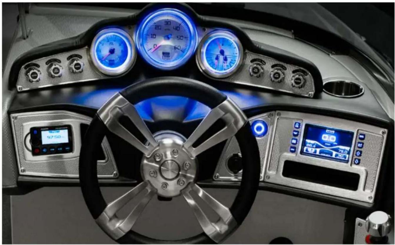
natural_image
Interior view of a modern car dashboard with illuminated gauges, steering wheel, and digital displays (no readable text or symbols)
text_image
Master CraftPRODUCT INFORMATION
The MasterCraft X-Series HV450 is designed for instrumentation and control on electronically controlled engines communicating via SAE J1939 and NMEA 2000. The display is a multi-functional tool that provides cruise control, rider profiles and enables equipment operators to view many different engine, ballast, transmission parameters and service codes. Included with the solution is an HV450 display unit.
CARE AND MAINTENANCE
Only basic cleaning should be required to maintain the 4.5" video touch screen at its best. A soft cloth can be used for cleaning the units. Typical window cleaner or rubbing alcohol can also be used to clean the glass portion of the video screen display. Do not use harsh or abrasive cleaners on the unit.
BASIC NAVIGATION FEATURES
All product features are easily accessed through Quick Access Keys, Soft Key commands and Menus.
Quick Access Keys
The following controls are accessed via the Quick Access Keys: Audio, Ballast/Trim, Gauges, Settings Menu and Profiles/Cruise. They are called quick access keys because a new screen can be accessed quickly by pressing the key.
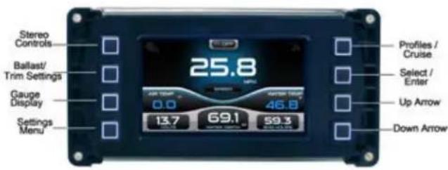
text_image
Stereo Controls Ballast/Trim Settings Gauge Display Settings Menu 25.8 AUR 100V 0.0 13.7 69.1 59.3 46.8 Profiles / Cruise Select / Enter Up Arrow Down ArrowSoft Key Commands
Once the desired screen is accessed, navigation within the screen is controlled with Soft Key commands. Soft Key commands override Quick Access key functions and are executed by pressing the keys to the side of the label.
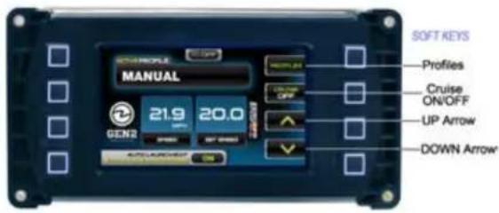
text_image
SOFT KEYS PROFILES Cruise ON/OFF UP Arrow DOWN Arrow MANUAL 21.9 20.0 GEN2FEATURES
The X-Series HV450 provides the following features:
- Audio/Stereo
- Gauges
- Ballast and Trim Tab settings
- Cruise Control
- Preset Rider Profiles
-
Settings Menu
-
Fuel Settings
- User Settings
- Service Information
+Engine Diagnostics - PDM Diagnostics
- Factory Settings
Audio
Stereo display and functionality controls reside on the MasterCraft boat. Here are a few screens available for viewing on the Stereo:
Fusion FM Channel
Fusion iPod Display
text_image
FU FU: 0.000000
text_image
iPhone For Noise Noise Pursing Body TenderFusion VHF Channel
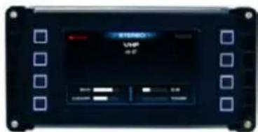
text_image
STUDIO UVP 0.47Ballast and Trim
The Ballast and Trim screen can be accessed by pressing the second Quick Access Key on the left side of the HV450.
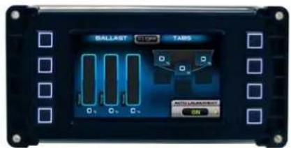
text_image
BALLAST STOP TABS OFF-IN-STOP ONThis screen shows the ballast tank fill and empty activity in addition to the trim tab levels. The only soft key on this screen is the Auto Launch/Exit key. Press this key to turn Auto Launch/Exit ON or OFF.
Gauges
Access the gauges screen by pressing the third Quick Access Key on the left side of the HV450.
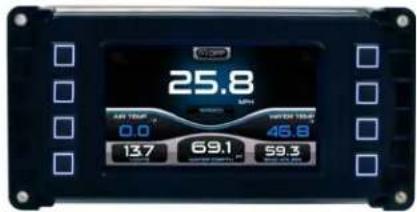
text_image
25.8 AIR TEM: 0.0 SHERAT TEMP: 46.8 13.7 69.1 59.3This screen shows the Speedometer, Air Temperature, Water Temperature, Battery Voltage, Water Depth and Engine Hours Gauges.
NOTE: This screen is display only. There are no soft keys with it.
Cruise/Profile
The Profiles screen can be accessed by pressing the first Quick Access Key on the right side of the HV450.

text_image
MANUAL 4.5 20.0 CENS2This feature displays rider/user profiles for cruise controls based on user preferences for speed, ballast and smart plate settings.
Cruise/Profile Screen Soft Key Commands
 | Use this key to access a list of preloaded profiles. Use the through the list. Press  profile. profile. |
 | Use this key to turn the cruise ON or OFF. This message will display when turning Cruise ON: Speed Control has been enabled. This message will display when turning Cruise OFF: Speed Control has been disabled. |
 | Use this key to increase set speed. |
 | Use this key to decrease set speed. |
 | Press and hold the Menu key to turn Auto Launch on or off. |
MAIN SETTINGS MENU
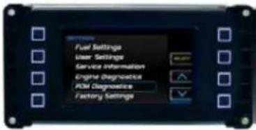
text_image
Fuel Settings User Settings Service Information Engine Diagnostics PCM Diagnostics Factory SettingsThe Main Menu screen for viewing engine statistics can be accessed by pressing the fourth Quick Access Key on the left side of the HV450. The following settings are available:
Fuel Settings
Enter the amount of fuel added to assist in proper fuel management.
User Settings
Customize the display options for ambient light and brightness, set US or metric units and other settings.
Service Information
Provides information about the software version, dealer, oil changes and dealer services.
Engine Diagnostics
Displays a list of engine fault codes and descriptions; on some engines, corrective action will be shown.
PDM Diagnostics
Displays power distribution module information (short circuit, overcurrent, open circuit and no fault) for various electrical input and output components of the craft.
Factory Settings
Displays settings for boat model, center tab, surf tabs, depth/water temperature, dealer and stereo. NOTE: These settings require a dealer code to access them.
NOTE: Some settings require a dealer code for access.
Fuel Settings
When power is first applied to the unit, the following screen appears:
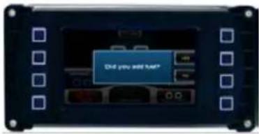
text_image
Did you add hard*If you select Yes (by pressing the second button on the right side), the following screen will appear. First screen that appears when you select Fuel Settings:
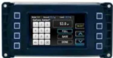
text_image
Fuel U1 Fuel Rate 10.0 g Fuel 10.0 g Fuel Type Adder? 53.0 μm FILL SAVE DONEProcedure To Enter Added Fuel
| Step | Action |
| 1 | If the blue highlighting (shown above on the Full line) is not surrounding the box that contains 0.0 gal, utilize the up arrow by pressing the third button on the right side until 0.0 gal is highlighted. |
| 2 | Press the second button on the right (Select). |
| 3 | The cursor will position under the first 0, and yellow high-lighting will surround the number 1. Utilize the up arrow (third button) until the yellow highlighting surrounds the appropriate first digit of the amount of fuel added. |
| 4 | Press Select (second button on the right). The cursor then moves to the second digit. |
| Step | Action |
| 5 | Utilize the up arrow once again (third button) until the yellow highlighting surrounds the appropriate second digit of the amount of fuel added. |
| 6 | Press Select (second button). Once all four digits have been entered, the blue highlighting will automatically go to Save. Press Select again. |
| 7 | Press Back to exit Fuel Settings (fourth button on the left side). |
NOTE: If the amount of fuel added has filled the tank, simply choose Full and select Save. If the amount of fuel added plus the existing fuel is greater than the tank capacity, the display automatically reverts to Full. To subtract fuel enter the correct amount to subtract, and touch the +/- button
User Settings
The User Settings option provides the user a way to specify viewing preferences. The settings are all editable by using the soft keys to the right of the option. There are two user settings screens.
User Settings Soft Key Commands
NEXT PAGE - advances to the next or previous page of settings
CHANGE - changes the currently selected setting
DOWN ARROW - highlights the next setting
BACK - returns to the Main Settings Menu
PLUS - increases the setting value
MINUS - decreases the setting value
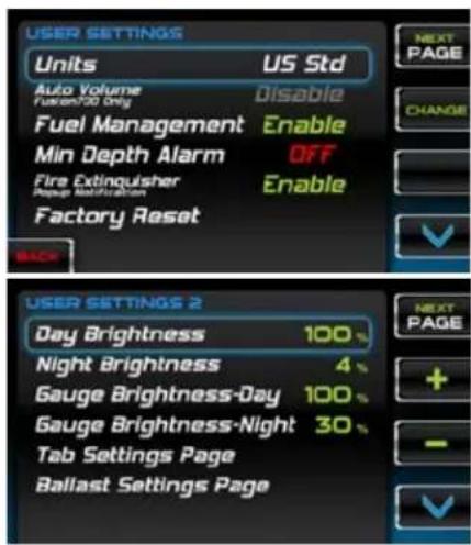
text_image
USER SETTINGS Units US Std Auto Volume Fusion700 OnlyDisable Fuel Management Enable Min Depth Alarm OFF Fire Extinguisher Enable Factory Reset BACK NEXT PAGE CHANGE USER SETTINGS 2 Day Brightness 100 % Night Brightness 4 % Gauge Brightness-Day 100 % Gauge Brightness-Night 30 % Tab Settings Page Ballast Settings Page NEXT PAGEUSER SETTINGS DESCRIPTIONS
| Function Description | |
| Units Options: | US Standard (US STD).Metric |
| Auto Volume Options: | Settings 1-5Disable |
| Fuel Management Options: | EnableDisable |
| Min Depth Alarm Options: | OFFIncrements of 1/2ft from 1 to 100ft. |
| Fire Extinguisher Options: | Enable (Pop-up)Disable (Pop-up) |
| Factory Reset Restores all factory settings to their original values.Option:YESNO | |
| Function Description | |
| Day Brightness Sets the screen brightness for daylight. Options:1-5% (increment of 1%)10-100% (increments of 10%) | |
| Night Brightness Sets the screen brightness for nighttime. Options:1-5% (increment of 1%)10-100% (increments of 10%) | |
| Gauge Brightness - Day | Sets the gauge brightness for daylight. Options:10-100% (increments of 10%) |
| Gauge Brightness - Night | Sets the gauge brightness for nighttime. Options:10-100% (increments of 10%) |
| Tab Settings Page | Provides the user with the opportunity to control the tab positions for the center and surf tabs on the boat.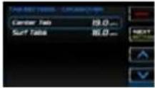 Using the up and down arrows, change the speed of the Center tab. When done, press Next Setting (second button on the right). In the same manner, change the speed of the surf tabs. When finished, touch Back (first button on the right side). Using the up and down arrows, change the speed of the Center tab. When done, press Next Setting (second button on the right). In the same manner, change the speed of the surf tabs. When finished, touch Back (first button on the right side). |
| Function Control | |
| Ballast Settings Page | Control the ballast fill and drain times.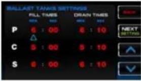 To adjust the fill and drain times use the soft keys. Press the Next Setting button to move between the times. Press the up and down arrow buttons to adjust the minutes and seconds. Press Back when finished. To adjust the fill and drain times use the soft keys. Press the Next Setting button to move between the times. Press the up and down arrow buttons to adjust the minutes and seconds. Press Back when finished. |
Service Information
Service information screens provide the ability for the user to view the software versions and allows the dealer to reset the oil change and the dealer service schedule.
NOTE: The Dealer Service Reset requires a dealer code to be entered before gaining access to the screens.
Software Version
Purely informational Software Version screens provide the following:
• Application version and part number
- Operating system version and part number
- Boot loader version and part number
- Software version
Oil Change Reset
Rest the oil change clock using the Oil change Reset Screen.
An Oil Change alert is displayed the first time after 10 engine hours.
Subsequent alerts are displayed at 50 engine hour intervals.
text_image
OIL CHANGE RESET Reset results a dealer table. If reset is removed, please contact your dealer. Reset oil change? YES NODealer Service Reset
Service is required for the engine every 100 hours. When 100 engine hours has been reached, an alert is displayed to perform maintenance service on the engine.
NOTE: To enter the dealer code, use the up
and down arrow soft keys, then press the Next soft key. Press the OK soft key when finished.
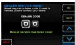
text_image
DEALER SERVICE RESET Reset requires a dealer code if reset is needed, please contact your dealer. DEALER CODE Dealer service has been reset
text_image
DEALER SERVICE RESET Reset requires a dealer code, if reset is needed, please contact your dealer. DEALER CODE OK NEXT ↓ ↓ BACK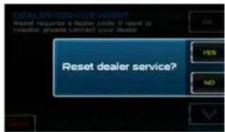
text_image
Dealer Service Reset? Reset request a dealer code if target is required, press sent to your dealer. Reset dealer service?NOTE: To enter the dealer code, use the up and down arrow soft keys, then press the Next soft key. Press the OK soft key when finished.
Engine Diagnostics
When choosing this selection, the display will query the engine(s) ECU, as illustrated below, and provide feedback on any diagnostic codes that have been activated and stored in the ECU for service needs.
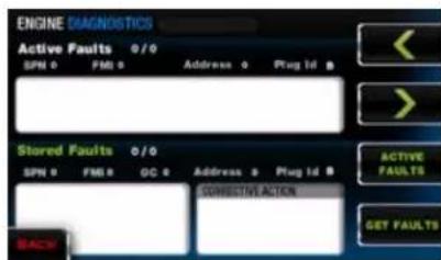
text_image
ENGINE DIAGNOSTICS Active Faults 0/0 SPIN 0 FMB 0 Address 0 Plug Id 0 Stored Faults 0/0 SPIN 0 FMB 0 OC 0 Address 0 Plug Id 0 CORRECTIVE ACTION BACK ACTIVE FAULTS GET FAULTSThe following is a list of definitions for the fields on the ENGINE DIAGNOSTICS screen:
Active Faults/Stored Faults
Shows the number of active faults and which fault number is currently being displayed. To advance to the next fault, select and select back to the previous fault. Selecting [BACK] returns to the Settings Menu. To navigate between the Active and Stored faults, use the STORED FAULTS/ACTIVE FAULTS soft keys.
SPN — Suspect Parameter Number - fault code
If not translated into text by the display, see the engine manufacturer's literature for the definition of the SPN number.
MI — Failure Mode Indicator - fault code
The FMI is defined by SAE J1939. If not translated into text, see the SAE standard or the engine manufacturer's literature.
Description Field — Most common SPNs and FMIs have text for the
description stored in the display. If there is no text, then this SPN and FMI must be defined by referring to the engine manufacturer or the SAE J1939 standard.
NOTE: This field is only used with certain brands and models of engines.
Corrective Action — see dealer.
Get Faults
Selecting Get Faults queries the engine(s) ECU for feedback on diagnostic codes that have been activated and stored in the ECU for service needs.
Fault Code Pop-ups
A fault condition will trigger a pop-up dialog box on the screen describing the nature of the fault.
How to Hide/Show Faults
To hide the fault code pop-up being displayed on the screen, press the soft key next to the Hide icon. The pop-up will disappear, however the Warning or Stop icon will remain on the screen to indicate there is still a fault. Pressing Hide does not clear the fault; it only hides the pop-up message.
When a fault code is hidden, a Show icon remains in the bottom right corner. When this soft key is pressed, the fault code displays.
Scrolling Through Multiple Messages
The title-bar of the fault code pop-up may indicate multiple messages, as in Diagnostic Message 1 of 3. Press scroll through the different messages.
PDM Diagnostics
These screens will display color-coded faults that exist in the system inputs and outputs of the engine.
Reported conditions include no faults, short circuits, open circuits and over-currents for the following Input and Output components:
| Inputs Outputs | ||
| PDM 1 | Forward Ballast Forward | Ballast Fill and Drain |
| Port Ballast Port Ballast | Fill and Drain | |
| Starboard Ballast Starboard | Ballast Fill and Drain | |
| Forward and Reverse Throttle Ind. | Port Tab Deploy | |
| Center Tab Port Tab Retract | ||
| Surf Tabs Starboard Tab | Deploy | |
| Fire Extinguisher Starboard Tab Retract | ||
| Navigation Lights Center | Tab Deploy | |
| Air Temp. (Analog) Center | Tab Retract | |


| PDM2 | Courtesy Lights Forward Ballast Fill and Drain |
| Tower Lights Starboard Ballast Fill and Drain | |
| Anchor Lights Port Ballast Fill and Drain | |
| Underwater Lights Blower | |
| Navigation Lights Navigation, Anchor, Tower Lights | |
| Blower Underwater and Courtesy Lights |
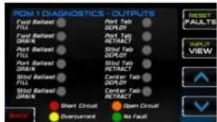
text_image
PDM1 DIAGNOSTICS - OUTPUTS Fuel Rearset FILL Fuel Rearset DRAIN Port Rearset FILL Port Rearset DRAIN Stbd Tap FILL Stbd Tap DRAIN Stbd Tap FILL Stbd Tap DRAIN Short Circuit Overcurrent Open Circuit No Fault RESET FAULTS VIEW OK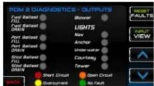
text_image
PDN 2 DIAGNOSTICS - OUTPUTS Ford Based Fill Ford Based DRAIN Port Based Fill Port Based DRAIN Stod Based Fill Stod Based DRAIN Short Circuit Overcurrent Blower LIGHTS Nav Anchor Underwater Courtesy Tower Open Circuit No Fault PALLTS VIEW
As between showing the Inputs and the Outputs.

Alternate allows the user to clear existing faults.
Factory Settings
This screen allows the dealer to indicate or display the following:
- Boat Model
• Center Tab (ON or OFF) - Surf Tabs (ON or OFF) Depth / Water Temperature (ON or OFF)
- Dealer Information (address, phone number)
- Stereo Information (Standard, High Power, Premium)
NOTE: A Dealer Code is required to gain access to this screen.
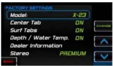
text_image
FACTORY SETTINGS Model: X-23 Center Tab ON Surf Tabs ON Depth / Water Temp. ON Dealer Information Stereo PREMIUMTROUBLESHOOTING
Display appears not to work or doesn't come ON.
- Display could be in sleep mode. Select a key on the keypad to activate the display.
- Check for loose connections at battery and display unit.
- Check for reversed polarity on the power connections.
- Verify battery has a minimum voltage of 6 volts.
Display resets or goes OFF when starting engine.
- Check display supply wires are connected properly to battery.
- Verify battery is charged properly.
- Check battery for efficient starter current.
Display has no back light.
Contact your MasterCraft service center.
Display has no keypad back light.
Contact your MasterCraft service center.
natural_image
Interior view of a vehicle dashboard with multiple digital displays and steering wheel (no visible text or symbols)2016 OWNERS MANUAL / 0125
PRODUCT INFORMATION FOR THE XSTAR VIDEO TOUCH AND STATIC (NON-TOUCH) SCREENS
The XStar video screens consist of one (1) 4.5" video touch screen, one (1) 4.5" static, non-touch screen, and one (1) 7" touch screen. A unique feature is that the 4.5" video touch screen and the 7" touch screen are linked.
Some changes made on either are displayed on both. The 4.5" static, non-touch screen is independent of the other two screens and displays engine and transmission parameters and service codes. These are multi-functional tools that provide GPS tracking, multi-media display, cruise control, rider profiles, and enables equipment operators to view a wide range of engine, ballast, transmission parameters and service codes.
CARE AND MAINTENANCE
Only basic cleaning should be required to maintain the screens at their best. A soft cloth can be used for cleaning the units. Typical window cleaner or rubbing alcohol can also be used to clean the glass portion of the video screen display. Do not use harsh or abrasive cleaners on the unit.

CAUTION
Avoid contact between sharp or hard objects and the video touch screen because this can result in scratches or other permanent marks on the screen. Clean only with a soft cloth, using window cleaner or rubbing alcohol only. Never use harsh or abrasive cleaners on the unit, as this may result in damage to the unit that is not covered under warranty.
BASIC NAVIGATION FEATURES
All features are easily accessible through the quick access keys, touch point commands and menus. Some navigation is linked between the 4.5" touch screen and the 7" touch screen, with data shared between the units.
SCREEN
4.5" Static, Non-Touch Screen
The 4.5" static, non-touch screen displays the gauges associated with the engine in both the gauge view and the digital view.
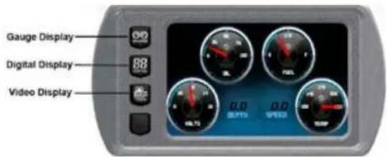
text_image
Gauge Display Digital Display Video DisplayIt also displays the video. The following displays can be accessed via the Quick Access Keys: Gauges, digital gauges and video on the 7" touch screen.
7" Non-Touch Screen
The following controls are accessed via the Quick Access Keys:
Cruise control, skier profiles, stereo, GPS, home, cruise ON/OFF, scroll up and scroll down. When the Menu key is pressed once, the "On Screen Menu" is displayed on both the 7" and 4.5" touch screens. When the Menu key is pressed and held, the Main Menu is displayed and provides access to the settings menu through
a selection of soft keys. Soft key commands provide additional features and navigation shortcuts. Depending on the current screen displayed, the soft keys may appear as icons or as a vertical control bar.
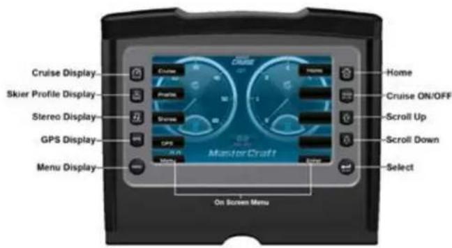
text_image
Cruise Display Skier Profile Display Stereo Display GPS Display Menu Display On Screen Menu Cruise Home Cruise ON/OFF Scroll Up Scroll Down Select MasterCraft4.5" Touch Screen
(Right) The 4.5" touch screen functions can be accessed through the Quick Access Keys on the left and right of the display screen or operated through the touch screen.
Although most of the functionality is available through touching the screen, not everything can be accessed in that manner. For example, menu items displayed on the screen are accessible only through the Quick Access Keys. The following controls are accessed via the Quick Access Keys: Lights, climate control, video control,
stereo control, cruise control, profiles, ballasts, and attitude adjustment and surf tabs.
Function and Description

UP or Increase Value—Touch to increase the value displayed.
NOTE: Depending on what screen is displayed, this icon can also represent moving the highlight up.

Down or Decrease Value—Touch to decrease the value displayed.
NOTE: Depending on what screen is displayed, this icon can also represent moving the highlight down.
Previous—Touch to go to the previous screen.
Next—Touch to advance to the next screen.

Exit—Touch to exit without saving.

Breadcrumb Trail—Touch the dots to move between screens.
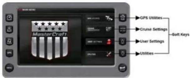
text_image
GPS Utilities MasterCraft Cruise Settings Soft Keys User Settings Utilities
text_image
LIGHTS CONTROL Display Climate Control Display Video Control Display Stereo Control Display CLIMATE Cruise Control Display Profiles Control Display Ballast Control Display Trim Tabs Display 32° 50° AIR WARGSQUICK ACCESS/KEY FEATURES
This section describes the features accessed through the Quick Access Keys located to the left and right of the display.
Cruise—The set speed can be adjusted on either the 4.5" touch screen, using the touch points, or the 7" touch screen using the UP and DOWN arrow keys. If the set speed is changed on one, the change is reflected on the Rider Profiles
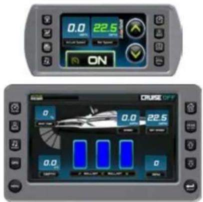
text_image
0.0 22.5 AC/DC Speed No Speed ON CRUISE OFF 0.0 22.5 0.0 0.0 COSCO C BULLIP C BULLIP C 0The Rider Profiles screen is accessible by pressing the Quick Access Key on either the 4.5" or 7" touch screens. This feature displays rider/user profiles for cruise controls based on user preferences for speed ballast, and attitude adjustment (trim) and surf
tabs. Up to 16 rider/user profiles can be defined. Rider profiles can also be uploaded via a USB connection.
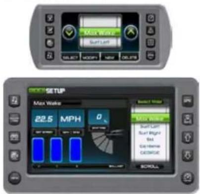
text_image
Max Wake Suff Left SELECT HOLDUP NEW DELAYS BOOT SETUP Max Wake 22.5 MPH 0 Suff Left Suff Right End Ex-Home DCORGE SROLLProfiles Screen—Touch Point Commands
Profiles—provides utilities for adding new users and editing/deleting existing users.
Touch Point Commands for Profiles include:
UP—DOWN—when positioned in the "Name field UP/DOWN arrows move from profile to profile.
SELECT—Selects the current rider/user profile and displays some information on the 4.5" screen and a compilation of all user information on the 7" screen.
NEW—provides an interface to add new user information.
MODIFY—select and edit existing user name information. DELETE—deletes selected user name after confirmation warning.
NEW RIDER PROFILE
A new rider profile can be set up using the 4.5" touch screen.
Function and Description
To create a new profile, press [PROFILE] on the 4.5" touch screen.
NEW—Touch [NEW] on the 4.5" touch screen to create a new profile. A Changing Data pop-up will be displayed on the 7" touch screen and will continue to be displayed until the new user is saved.
text_image
GEORGE SETUP 28.0 MPH 0 Changing Data...Type a name for the new profile using the keypad and touch [DONE].
text_image
GEORGE NAME 28.0 MPH 0 Changing Date...Touch [RIGHT ARROW] key following [NAME]. Touch [EXIT] to exit the screen and return to the Profile Menu.
text_image
4.0 MPN SPEED
text_image
SWEET SETUP SAY 28.0 MPH 0 Changing Data... Control Panel CHANGE SAY SAY Change ROLLTouch [UP ARROW] or [DOWN ARROW] to change the Set Speed settings.
Touch [RIGHT ARROW] to move to the Ballast screen or [LEFT ARROW] to return to the Name screen. Touch [EXIT] to exit the screen and return to the Profile Menu.
The ballasts are set by touching the ballast tank you want to set and sliding your finger on the screen to the desired setting. While the ballast fill indicator is red, the ballasts are not full. When they are full, the ballast fill indicator turns green. Touch the [RIGHT ARROW] to move to the Tabs screen or [LEFT ARROW] to go back to the Speed screen. Touch [EXIT] to exit the screen and return to the Profile Menu.
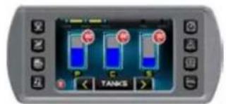
text_image
C C C TANKS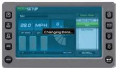
text_image
MILKING SETUP S/N 28.0 MPH 0 Changing Date... SELLTouch [MINUS] button to decrease the percentage, or the [PLUS] screen to increase the percentage of tab adjustment. When the satisfactory level is reached, touch the [RIGHT ARROW] to move to the Profiles save screen or the [LEFT ARROW] to move to the previous Ballast screen.
Touch [EXIT] to exit the screen
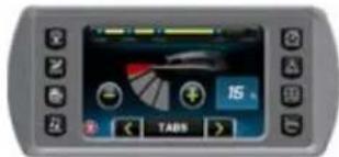
text_image
Digital display screen showing a speedometer interface with Chinese text and icons, including '15' and 'TABN'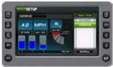
text_image
GEORGE 4.0 MPH 15 Screw Filter 20000000 20000000 SCROLLTouch [SAVE] to save the new rider and settings created. The composite profile is now displayed on the 7" touch screen.

SELECT—Touch [SELECT] to see the rider profile. The 4.5" touch screen displays the cruise settings while the 7" touch screen displays a composite of all the settings.

MODIFY—Touch [MODIFY] to modify the settings for the current rider. Follow the steps for setting up New Profiles and touch [SAVE] when finished.
DELETE—Touch [DELETE] to delete the profile. Displays the following alert:

text_image
Delete User Profile? SELECT NO IFN YES DELETETouch [NO] to keep or [YES] to continue the deleting process.
MODIFY RIDER PROFILE
A rider profile can be modified using the 4.5" touch screen.
Function and Description
To modify a profile, press [PROFILE] on the 4.5" screen.
MODIFY—Touch [MODIFY] to change an existing profile.
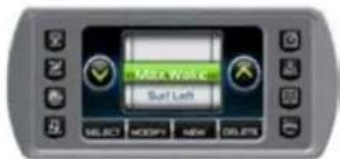
text_image
Max Wake Multi Left Multi Left SELECT Modify More DeleteIf the name requires modification or to replace it, touch the name to display the keyboard. Backspace through the existing name and type a new name for the profile using the touch keypad and touch [DONE]. If the name does not require a change, move to the next step.
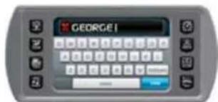
text_image
GEORGE!Touch the [RIGHT ARROW] to move to the Speed settings or [LEFT ARROW] to return to the Name screen.
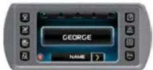
text_image
GEORGE NAME >Touch [RIGHT ARROW] to move to the Ballast screen.
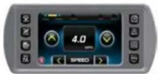
text_image
4.0 SPEEDThe ballasts are modified by touching the ballast to be set and sliding your finger on the screen to the desired setting. While the ballast fill indicator is red, the ballast tanks are not full. When they are filled, the ballast fill indicator turns green. Touch [RIGHT ARROW] to move to the Tabs screen or [LEFT ARROW] to move back to the previous screen.
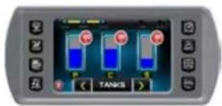
text_image
P C S TANKS
text_image
Screenshot of a mobile device interface showing a digital display with a speedometer and control buttonsTouch [SAVE] to save the rider and settings as modified. The composite profile can be displayed on the 7" touch screen.
STEREO DISPLAY
The Stereo Display is accessible by pressing the Quick Access Key. This feature provides universal control to the stereo, mimicking all the controls of a standard remote control. This includes iPod and thumb drive music.
NOTE: When Cruise is ON, the buttons on the 7" touch screen can control set speed. UP—DOWN—increases or decreases the target speed.
Stereo Display—Soft Key Commands
Function and Description

VOLUME UP—increases the volume.

VOLUME DOWN—decreases the volume.

PREV TRACK—returns to and plays the previous track of the current medium.

NEXT TRACK—moves to and plays the next track of the current medium.

PLAY/PAUSE—toggles between Play and Pause modes when a CD is playing.

SOURCE—chooses between iPod, USB port or stereo.

MUTE—mutes the stereo volume.

POWER ON/OFF
GPS DISPLAY
The GPS screen is accessible by pressing the Quick Access Key on the 7" touch screen. The GPS feature displays map data, latitude and longitude coordinates, time and speed. Navigating the map is performed through the 4.5" touch screen
NOTE: To access GPS navigation, press [SELECT] as shown.
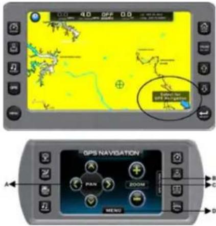
text_image
4.0 OFF 0.0 SARLIC GPS NAVIGATION A B C D PAN ZOOM MENUSection A: PAN—Moves the map cursor on the 7" touch screen to the left, right, up and down the map by touching the appropriate arrow.
Section B: GPS UTILITIES—An optional menu to access the utilities for managing waypoints, tracks, chart and time set-up, depth and position settings, and checking the GPS status. For more information about the utilities, see GPS Utilities under the Menu Options.
Section C: ZOOM IN and OUT—Touch [PLUS] button to zoom in on a location on the map, and [MINUS] button to zoom out for a broader view.
Section D: MENU—Use this menu to go to the current position on the map, create waypoints and create, clear and save tracks.
GPS Display—Soft Key and Touch Point Commands
Select for GPS Navigation—Press the [SELECT] key on the 7" screen to bring up the GPS Navigation screen on the 4.5" screen.
ZOOM IN/ZOOM OUT—Zooms in or out on the map. Touch [PLUS] button
on the 4.5" touch screen to zoom in on a location on the map displayed on the 7" touch screen, and [MINUS] button to zoom out for a broader view.
PAN—Touch of the direction arrows on the 4.5" touch screen to move the cursor position across the map displayed on the 7" touch screen in that direction.
GPS Utilities Menu
Touch the GPS Utilities tab on the right side of the GPS Navigation screen. The following menu slides into position:
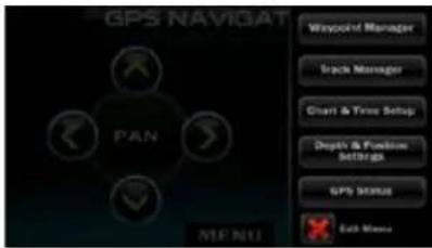
text_image
GPS NAVIGATION PAN WAYPOINT Manager Track Manager Chart & Time Setup Depth & Function Settings GPS STATUS Each MemoryThe following utilities are provided directly from this menu on the 4.5" touch screen. They are the identical utilities as the ones provided on the 7" touch screen under the Setting Menu. The only difference is that the functions are provided through touch points commands on the smaller device.
Waypoint Manager
The advantage to using the Waypoint Manager on the 4.5" touch screen is that the results can be immediately seen on the map displayed on the 7" touch screen. For example, if the [GO TO] button is touched, the map cursor is immediately moved to the selected waypoint and the map is zoomed in to the maximum level. The Waypoint Manager can be closed by touching [X].
From this screen, the following can be accomplished:
- Waypoint name can be edited;
- Waypoint icons selected;
- Waypoints can be deleted;
- Single waypoint;
- All waypoints;
- GO TO a waypoint on the map.
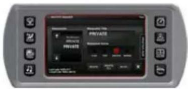
text_image
PRIVATE PRIVATE PRIVATE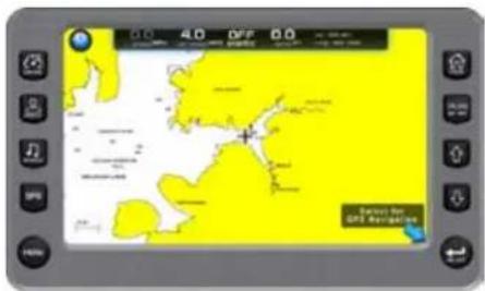
text_image
0.0 4.0 DFF 0.0 DIF Select for GPS NavigationTrack Manager
The advantage to using the Track Manager on the 4.5" touch screen is that the results can be immediately seen on the map displayed on the 7" touch screen. The Track Manager can be closed by touching [X].
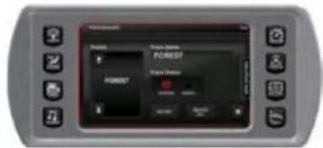
text_image
FOREST Status: FOREST FREESTFrom this screen, the following can be accomplished:
- Track name edited;
- Tracks shown or hidden;
- Tracks deleted;
- Single track;
- All tracks.
NOTE: For more information on managing tracks, see GPS Utilities under the Settings Menu.
Chart and Time Set-up
The advantage to using the Chart and Time Set-up on the 4.5" touch screen is that the results can be immediately seen on the map displayed on the 7" touch screen. For example, if [SHOW GRID] is turned on, the grid lines are immediately shown on the 7" touch screen map The Chart and Time Set-up screen can be closed by touching [X].
NOTE: For more information on the functions of the Chart and Time Setup screen, see GPS Utilities under Menu Options.
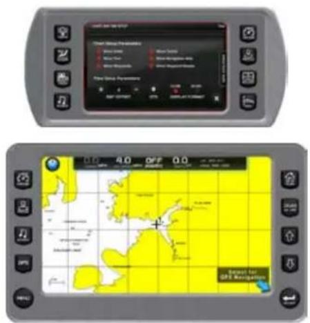
text_image
GPS NAV Control Group Parameters Blue Line White Line Red Line White Line Blue Line White Line Control Group Parameters Blue Line White Line Control Group Parameters 0.0 0.1 0.2 0.3 0.4 0.5 0.6 0.7 0.8 0.9 1.0 A.O O.F.P Q.O GPT GPT NavigationDepth and Position Set-up
Use the Depth and Position Set-up on the 4.5" touch screen and the results can be immediately seen on the map displayed on the 7" touch screen.
For example, modify the Depth Contour or the Safety Contour, the contours are immediately shown on the 7" touch screen. The Depth and Position Setup screen can be closed by touching [X].
text_image
Status and Status Settings 1. Status: 0.0000 2. Status: 0.0000 3. Status: 0.0000 4. Status: 0.0000 5. Status: 0.0000 6. Status: 0.0000 7. Status: 0.0000 8. Status: 0.0000 9. Status: 0.0000 10. Status: 0.0000 11. Status: 0.0000 12. Status: 0.0000 13. Status: 0.0000 14. Status: 0.0000 15. Status: 0.0000 16. Status: 0.0000 17. Status: 0.0000 18. Status: 0.0000 19. Status: 0.0000 20. Status: 0.0000 21. Status: 0.0000 22. Status: 0.0000 23. Status: 0.0000 24. Status: 0.0000 25. Status: 0.0000 26. Status: 0.0000 27. Status: 0.0000 28. Status: 0.0000 29. Status: 0.0000 30. Status: 0.0000 31. Status: 0.0000 32. Status: 0.0000 33. Status: 0.0000 34. Status: 0.0000 35. Status: 0.0000 36. Status: 0.0000 37. Status: 0.0000 38. Status: 0.0000 39. Status: 0.0000 40. Status: 0.0000 41. Status: 0.0000 42. Status: 0.0000 43. Status: 0.0000 44. Status: 0.0000 45. Status: 0.0000 46. Status: 0.0000 47. Status: 0.0000 48. Status: 0.0000 49. Status: 0.0000 50. Status: 0.000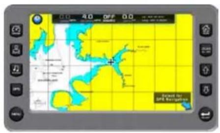
text_image
A.D. A.D. OFF D.D. Bened to Bird NavigationGPS Status
The GPS Status screen on the 4.5" touch screen is identical to the GPS Status screen on the 7" touch screen. It shows the status of detectable satellites and their locations.
text_image
Digital display screen showing a circular grid pattern with control buttons and status indicatorsTrack Menu
Touch menu to:
• Find the current position on the map;
- Create waypoints;
- Clear track;
- Save track.
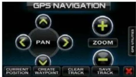
text_image
GPS NAVIGATION PAN ZOOM CURRENT POSITION CREATE WAYPOINT CLEAR TRACK SAVE TRACK GPS UTILITIESCURRENT POSITION—The position of the boat. A track begins recording from the current position and continues to record until the track is cleared or saved.
CREATE WAYPOINT—Touch this button to create a waypoint at the
current position of the cursor on the map. When this button is touched a keyboard is displayed to type a name for the waypoint. When [DONE] is touched, the waypoint is placed on the map and can be managed through the Waypoint Manager.
CLEAR TRACK—Touch this button to clear the currently recording track.
SAVE TRACK—Use this button to save the currently recording track.
When this button is touched, a keyboard is displayed to type a name for the track. When [DONE] is touched, the track is diagramed on the map.
MAIN MENU OPTIONS
Menu Options
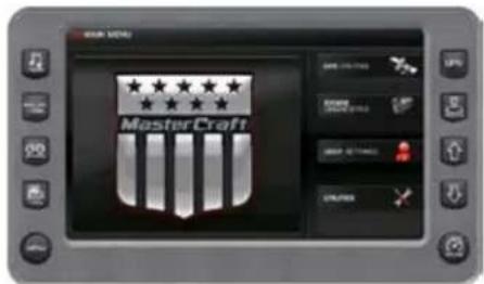
text_image
MasterCraftThe Menu is displayed by pressing and holding [MENU]. The following features are available:
GPS Utilities—Contains options to set up track and position, chart and time, and waypoint manager. Also displays satellite status.
User Settings—Allows you to customize the display options for ambient light and brightness, set U.S. or metric units, specify the Home screen and screen set-up status.
Engine Diagnostics—Displays a list of engine fault codes and descriptions; on some engines, corrective action will be shown.
Utilities—Allows configuration of the unit including wire configuration, plug address, fault conversion, CAN data, and fault codes. Also displays software version information at the top of the page.
- System
- Ballast
• Auto Launch/Exit Setpoint Speed
GPS UTILITIES
The GPS Utilities includes the following:
- Waypoint Manager
- Track Manager
• Chart and Time Set-up
• Depth and Position Settings
• GPS Status
Waypoint Manager
Waypoints are a way to mark specific locations by latitude and longitude.
After the waypoints are established, the Waypoint Manager allows
you to associate an icon with them for identification. Use the [LEFT] and [RIGHT] arrows to navigate the screen. Delete a single waypoint by using the [DELETE] key, or all of them at once with [DELETE ALL] (a delete alert is displayed). Pressing the [GO TO WPT] key displays the GPS screen containing the currently highlighted waypoint.
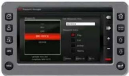
text_image
Static Manager Static Manager BIG ROCK LOGIC Frequency Input Output Balance Balance On OK CancelWaypoint List—Displays a list of the waypoints that have been set. Use the [UP] and [DOWN] keys to highlight the desired waypoint.
Waypoint Icon—Allows you to assign one of four different icons to any of the waypoints listed.
LAT/LON—Displays latitude and longitude values for the currently highlighted waypoint on the list.
Track Manager
Multiple tracks for displaying on the GPS map can be set up. The Track Manager is a way to select tracks to "show" on the map or "hide" a map you are not currently using. [DELETE] one track or [DELETE ALL TRACKS] at once (a delete alert is displayed).
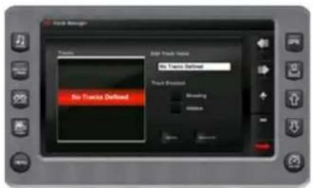
text_image
Track Manager Tracks Side Track Name No Tracks Defined Track Breakout Blending 1000mm No Tracks DefinedTracks List—Lists all the tracks saved on the device.
Edit Track Name—Enables the user to edit the Track Name.
Track Enable—Shows or hides the selected Track.
Chart and Time Set-up
This menu option allows the set-up for viewing options for the GPS Display.
Chart Set-up Parameters—Use the [PLUS] and [MINUS] soft keys to select the information you want displayed on the GPS screen.
Time Set-up Parameters—This is used to select correct time zone and clock mode for either 12-hour or 24-hour time formats. You can also enable DST (Daylight Savings Time) by using the [PLUS] or [MINUS] soft keys to select the box.
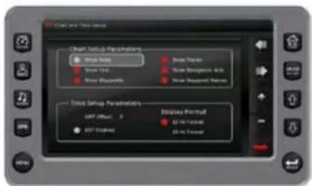
text_image
Chart and Tree Settings Chart Setup Parameters Show Data Show Yid Show Histograms Show Image Show Histograms &G Show Image Number Show Setup Parameters GPT Offset: 0 VSP Offset Display Format 62 Hz Format 24 Hz FormatDepth and Position Settings
This feature allows for the definition of the amount of detail to display for longitude and latitude information on the GPS map and depth display.
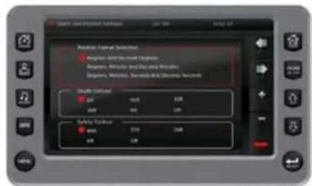
text_image
Airline and Response Settings Airline: Flight Selected Flight: Airline and Flight Options Flight: Flight And Airline Options Flight: Windows, Touch-and-Stop Connection Seconds Speed Limited Air 200 300 500 1000 200 300 500 Safety Time Air 200 300 500 600GPS Status
Shows the location of the satellites.
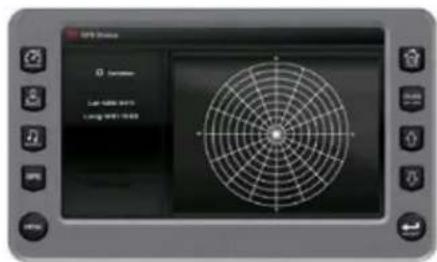
text_image
GPS System 0 Saturation Lap - 1200 MHz Lung - 1200 MHzENGINE DIAGNOSTICS
When choosing this selection, the display will query the engine's ECU, and provide feedback on any diagnostic codes that have been activated and stored in the ECU for service needs.
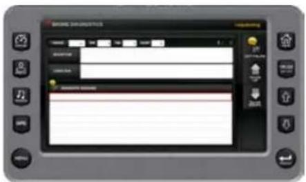
text_image
Screenshot of a mobile app interface with status bar, navigation buttons, and control buttonsEngine Diagnostics-Soft Key Commands
GET FAULTS—Queries the engine's ECU for feedback on diagnostic codes that have been activated and stored in the ECU for service needs.
UP—DOWN—Navigates through the fault list.
The following is a list of field definitions contained on the ENGINE DIAGNOSTICS screen:
Source—Identifies the component having the fault: engine 1, 2 or auxiliary.
Status—Indicates whether the fault has been corrected.
SPN—"Suspect parameter Number"—fault code. If not translated into text by the display, see an authorized MasterCraft dealer.
FMI—"Failure Mode Indicator"—fault code. The FMI is defined by SAW J1939. If not translated into text, see an authorized MasterCraft dealer.
Count—The number of times the event has been flagged.
Description—Most common SPNs and FMIs have text for the description
stored in the display. If there is no text, then this SPN and FMI must be defined by referring to the engine manufacturer or the SAE J1939 standard.
NOTE: This field is only used with certain models of engines.
Correction—Suggested action for correction.
Fault Code Pop-ups
A fault condition will trigger a pop-up dialog box on the screen describing the nature of the fault.
How to Hide/Show Faults
To hide the fault code pop-up being displayed on the screen, press the soft key next to the "Hide" icon. The pop-up will disappear.
However, the "Warning" or "Stop" icon will remain on the screen to indicate there is still a fault. Pressing "Hide" does not clear the fault; it only hides the pop-up message.
When a fault code has been hidden, a "Show" icon will remain in the bottom right corner. When this soft key is pressed, the fault code will again be displayed.
Scrolling Through Multiple Messages
The title bar of the fault code pup-up may indicate multiple messages, as in "Diagnostic Message 1 of 3." Press to scroll through the different messages.
USER SETTINGS
User Settings provide options to specify viewing preferences. Pressing [PREV] or [NEXT] navigates through the options, and [UP] and [DOWN] scrolls through the selections for each option.
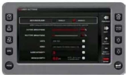
text_image
SIN MAXIMUM MAXIMUM MAXIMUM MINIMUM MINIMUM MINIMUMUser Settings-Soft Key Commands Function and Description

PREVIOUS —Provides the ability to navigate through the settings displayed on the screen. Selects the previous setting.

NEXT—Provides the ability to navigate through the settings displayed on the screen. Selects the next setting.

UP/INCREASE—Allows changing the values within the settings.

DOWN/DECREASE—Decreased the value in the setting.

ENTER—Creates a new user profile from the current cruise settings.
Settings include:
AUTO BACKLIGHT—This setting enables and disables auto backlighting feature. If enabled and the NAV Light is turned on, the displays will reduce the screen brightness.
DAYTIME BRIGHTNESS—The daytime brightness control can be set by using the [UP] and [DOWN] soft keys to change the settings in five percent (5%) increments until the desired brightness is achieved.
NIGHT TIME BRIGHTNESS—The night time brightness control can be set by using the [UP] and [DOWN] soft keys to change the settings in five percent (5%) increments until the desired brightness is achieved.
AUDIO INTENSITY—The Audio Intensity feature allows you to set values to automatically increase or decrease the audio volume according to what speed you are traveling.
MINIMUM DEPTH—This allows you to choose a minimum depth situation. Choosing zero turns this option OFF.
UTILITIES
System Information
The System Settings screen displays the current software version loaded on the unit. It is typically only accessed when the unit is first installed in order to configure the unit. You can set individual settings for the available options, or choose to select [RESTORE DEFAULTS] for the factory settings.
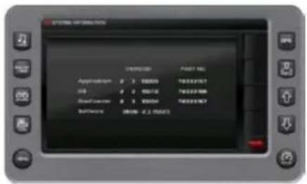
text_image
APPROVAL POST NO. Application # 3 00009 T833X157 URL # 2 00076 T833X788 SendToor# # 5 00004 T833X167 Software: 18006-2.2-05423BALLAST SETTINGS
Use the [NEXT] and [PREVIOUS] soft keys to navigate the settings. Use the Save soft key to save the modified settings.
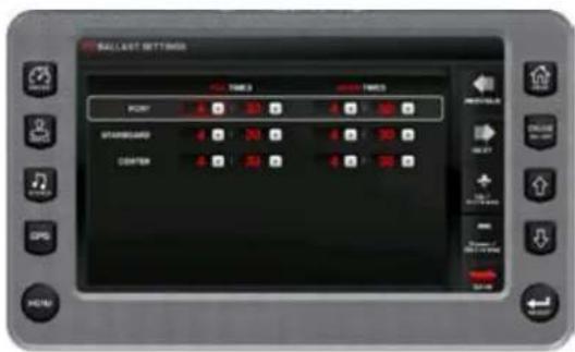
text_image
BALLAST SETTINGS TOMES TOMES POINT STANDARD CENTERTROUBLESHOOTING
Display appears not to work or doesn't come ON.
- Display could be in sleep mode. Touch a key on the keypad to activate the display.
- Check for loose connections at battery and display unit.
- Check for reversed polarity on the power connections.
- Verify battery has a minimum voltage of 6 volts.
Display resets or goes OFF when starting engine.
- Check display supply wires are connected properly to battery.
- Verify battery is charged properly.
- Check battery for efficient starter current.
Display has no back light.
Contact your MasterCraft service center.
Display has no keypad back light.
Contact your MasterCraft service center.

natural_image
A smiling girl in a life vest wading through shallow water, with splashes and water reflections visible (no text or symbols)PROSTAR ENGINE GAUGES
3-IN-1 GAUGE: FUEL GAUGE
Upper Half of Gauge
text_image
1420s V/P F 240 800 300-500 100-200 50 70-80 10-20 0Fuel gauge readings are approximate. This gauge is activated with the ignition switch. The rocking motion of the boat during normal operation will cause the fuel gauge to fluctuate. For a more accurate reading, make sure that the boat is level and there is little or no motion present.
A "low fuel" notice will come up on the video screen as a warning to return to shore and refuel. MasterCraft recommends that operators do not run the boat below a quarter of a tank, except as necessary to return to shore, and not until the boat has been operated enough times to develop an understanding of how the fuel gauge readings relate to the visual inspection of fuel remaining in the tank. Extending fuel usage beyond the known capability of the boat may cause the boat to run out of fuel and may leave you stranded off-shore.
Although it may be possible to see fuel in the bottom of the fuel tank, you still may not be able to operate the boat. The fuel pick-up system was designed to avoid introducing the small amount of water and debris that unavoidably accumulate in the bottom of the tank. Rather than relying on visual inspection, you should pay attention to the fuel gauge.
Further, it is not recommended to allow the fuel to fall below one-quarter of a tank full at any time as it may result in damage to the fueling system. (See the Fueling section of this Owner's Manual.)

CAUTION
Allowing the fuel level in the fuel tank to fall below one-quarter of a tank full may affect the reliability of the fuel pump or result in damage to the fuel pump, which is not covered under warranty.
3-IN-1 ENGINE OIL PRESSURE GAUGE
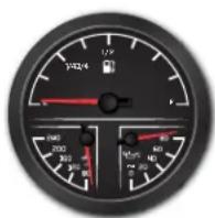
Lower Right Side
The engine oil pressure gauge indicates the pressure of the lubricating oil inside the engine. The average pressure ranges are between six (6) pounds per square inch (PSI) at 1000 RPM to 40 PSI or more at cruise-range speeds. A reading of pressure
below 5 PSI at 1000 RPM may be caused by a low oil level or other potentially serious problems that result in low oil pressure, causing a red warning light to appear at the bottom of the gauge.
If you experience low oil pressure, stop your engine immediately and check your oil level before operating again.

CAUTION
Do not continue to run the engine if the oil pressure is low. If you do, the engine may become so hot that it, or surrounding components, could catch fire. You or others could be burned and the boat seriously damaged. Check your oil level and add an appropriate amount of approved motor oil before operating again or have your boat serviced by your local authorized dealer's service department. Note that damage to your engine from inappropriate oil levels can be costly to repair. Such damage is not covered by your warranty.
3-IN-1 WATER TEMPERATURE GAUGE
Lower Left Side
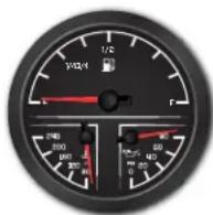
The temperature gauge indicates the water temperature inside the engine's cooling system as measured in degrees Fahrenheit. The normal operating temperature will range from 140 degrees Fahrenheit to 190 degrees Fahrenheit. Engines with electronic fuel injection also have a control circuit inside the
engine control module that will cause the engine to run at reduced speeds if the module senses that the engine is running too hot. If you notice that your speed has reduced during normal operation, but you have not manually slowed the throttle, monitor your temperature gauge.
If the gauge indicates excessive temperatures during operation, slow down immediately and turn off the engine. This indicates an engine problem that needs to be checked by the dealer!

CAUTION
Continuing to operate the boat while the temperature is above normal operating parameters may cause serious damage to your engine. Damage to your engine resulting from operating the engine in an overheated condition can be costly to repair. Such damage is not covered by your warranty!
The ProStar 7" video touch screen is a multi-functional tool that provides GPS tracking, multi-media display, cruise control, rider profiles, and enables equipment operators to view a wide range of engine, ballast, transmission parameters and service codes.
CARE AND MAINTENANCE
Only basic cleaning should be required to maintain the 7" video touch screen at its best. A soft cloth can be used for cleaning the units. Typical window cleaner or rubbing alcohol can also be used to clean the glass portion of the video screen display. Do not use harsh or abrasive cleaners on the unit.

CAUTION
Avoid contact between sharp or hard objects and the video touch screen because this can result in scratches or other permanent marks on the screen. Clean only with a soft cloth, using window
cleaner or rubbing alcohol only. Never use harsh or abrasive cleaners on the unit, as this may result in damage to the unit that is not covered under warranty.
BASIC NAVIGATION FEATURES
All features are easily accessible through the quick access keys, touch point commands and menus.
Quick Access Keys
The following controls are accessed via the Quick Access Keys: Audio, Ballast/Trim, Gauges, Video, Settings Menu, GPS, User Profiles, Cruise ON/OFF, Increase Value and Decrease Value. They are called Quick Access Keys because a new screen can be called up quite fast by pressing the key.
Touch Point Commands
After the desired screen is accessed, navigation within the screen is controlled with Touch Point Commands. These are executed by touching the screen in areas that are outlined with a highlighted bezel. In addition, there are areas where sliding a finger up or down can adjust settings. For example, on the Ballast and Tabs screen, sliding the finger on the screen on the inside of the tank area adjusts the ballast setting.
There are also areas in which sliding a finger from side to side will scroll through a list. When the slider bar on top of the screen is visible, sliding the finger across it will change screens.
NOTE: While the slide area may appear to be curved, it is, in fact, a straight line.
AUDIO
The Audio screen can be accessed by pressing the Audio Quick Access Key on the HV700. Press any Quick Access Key to exit this screen.
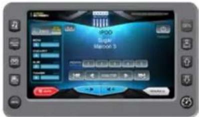
Touch Point Commands

POWER — Turns stereo system on/off.
SOURCE — Touch this to select a connected source. MasterCraft supports the following devices:
- FM radio
- AM radio
Sat - iPod/USB
DVD
VHF - Sirius XM Radio
- Auxiliary
• Regional Weather Channel

VOLUME — Touch this button to lower the volume.

VOLUME — Touch this button to raiser the volume.

VOLUME — Touch this button to mute the volume.

PREVTRACK — Plays the previous track current CD.

NEXTTRACK — Plays the next track of the current CD.
SCAN/STOP — Enables and stops the scanning of available channels.

REWIND — Touch this button to rewind the current selection.

FAST FORWARD — Touch this button to fast forward the current selection.

STEREO SETTINGS — Displays the following settings screen:
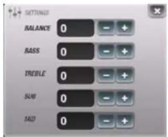
text_image
SETTINGS BALANCE 0 BASS 0 TREBLE 0 SUB 0 MAD 0Utilize the + and - buttons to adjust the settings.

iPod MENU — Touch this button to display the iPod menu, as shown below:
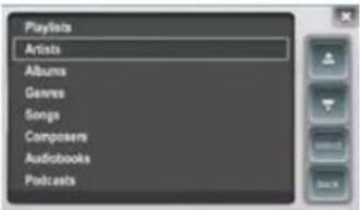
text_image
Playlists Artists Albums Genres Songs Composers Audiobooks PodcastsUtilize the Up and Down arrows, then touch Select when the appropriate choice is displayed.
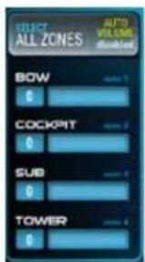
text_image
STRICT ALL ZONES AUTO VOLUME (Shelter) BOW 0 COCKPIT 0 SUB 0 TOWERZone Volume — Control the volume in the four zones of the boat by sliding your finger to the right or left on each line.
BALLAST & TRIM
The Ballast and Tabs screen can be accessed by pressing the Ballast/Trim Quick Access Key on the HV700. Press any Quick Access Key to exit this screen. This screen displays the current state of the ballasts and trim tabs.
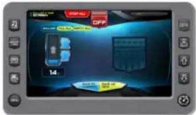
text_image
OFF 14NOTE: We are showing one Ballast on the Ballasts screen. Your dealer sets this option at 0, 1, or 2 Ballasts to fit your boat package.
Refer to the following chart for actions using the Touch Commands on this screen.
Touch to turn cruise control ON or OFF.

Touch and slide your finger to change screens.

Touch to stop all activity on this screen.
Touch to turn AUTO LAUNCH/EXIT ON or OFF. When Auto Launch is on, it automatically controls the center tab. When speed is above the Auto Launch speed the center tab will be retracted to 0% or if a profile is selected, it deploys the center tab to the profile setting. If the speed is above the Auto Launch speed and then decelerated below the Auto Launch speed, the tab deploys to 100 (crossover speed).
Touch to save the settings to the current rider profile.
NOTE: If no rider profile is selected, this does nothing.

Touch to save these settings to a new rider profile. A keyboard is displayed to name the new profile and the new profile process is launched. (See the Profiles section starting on page 10.)

Touch to fill all ballasts.
EMPTY ALL
Touch to empty all ballasts.
Touch and slide your finger to the desired Ballast Tank level, or touch the UP DOWN Arrows to obtain the level.
Touch and slide your finger to the desired Trim Tab position.
Gauge Screen Gage Display
- Speedometer (MPH)
• Water Depth (FT) - Air Temperature (F°)
- Water Temperature (F°)
- Battery Voltage (Volts)
• Engine Run Time (Hours)
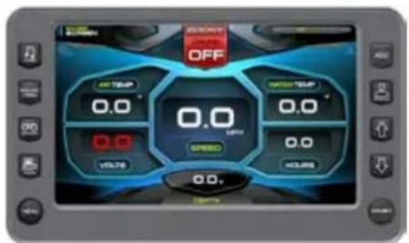
Touch Commands Description
Touch to turn cruise control ON or OFF.
VIDEO
The Video screen can be accessed by pressing the Quick Access Key. Press any Quick Access Key to exit this screen.
text_image
Tower Aux Video MediaTouch Commands Description
Touch to turn cruise control ON or OFF.

Touch to view the Tower video source. Press the Video Quick Access Key to go back.

Touch to view the Aux Video source. Press the Video Quick Access Key to go back.

Touch to view the Media video source. Press the Video Quick Access Key to go back.
HEATER AND LIGHTS
The Heater and Lights screen can be accessed by pressing the Quick Access Key. Press any Quick Access Key to exit this screen.
text_image
Security ON Heater Off Seat Heater Low Country Lights Storage LightsTouch Commands Description
Touch to turn cruise control ON or OFF.

Touch and slide your finger to change screens
text_image
Heater OFF Heater LOW Heater HIGH Seat Heater OFF Seat Heater LOW Seat Heater HIGH Courtesy Lights Courtesy Lights Touch to turnTouch to turn ON or OFF.
Touch again to choose a High or Low temperature setting.
Touch to turn ON or OFF.
PROFILES
The Profiles screen can be accessed by pressing the Quick Access Key.
This feature displays rider/user profiles for cruise controls based on user preferences for Set Speed, Ballast, and Tab settings. Up to 16 rider/user profiles can be created and stored.
To scroll through the available Profiles, slide finger across the information slide bar or press the Quick Access Keys and to view the list.


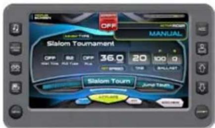
text_image
OFF MANUAL Slalom Tournament OFF B2 OFF 36.0 20 100 0 Real Time, Ball Toms, Pcs SPRING TIME BALLNET Slalom Tourn June TechTouch Commands Description
Touch to turn cruise control ON or OFF.

Touch to delete the selected rider after confirmation warning.
Touch to activate the user displayed in that event with all settings activated.
Touch to edit existing user or event name.

Touch to add a new rider. See the process in the next section.
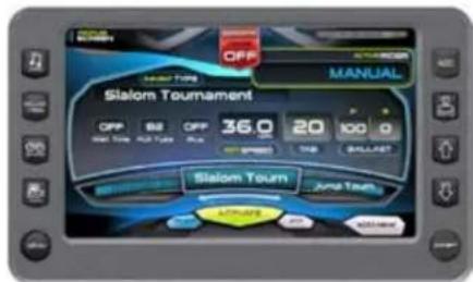
text_image
OFF MANUAL Slalom Tournament OFF 52 OFF 36.0 20 100 SALOM TOWN Jump TeachA new rider profile can be setup using the touch screen. To create a new profile, press the [Profile] Quick Access Key:
Touch [ADD NEW] to create a new profile.
Type a name for the new profile using the touch keypad and touch [DONE].
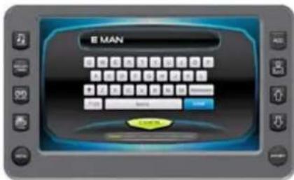
text_image
E MAN E MANTouch [NEXT] to continue.
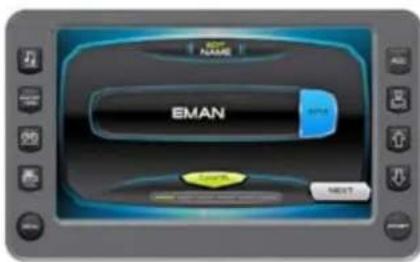
text_image
EMAN NEXTTouch the [UP] or the [DOWN] arrow to Set the speed for this profile.
Touch [Change] to set 3 Event Type.
Touch [Next] to continue.
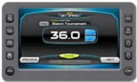
text_image
SET SPEED Salam Tournament 36.0 PREVIOUS NEXTSet the tab by either sliding the finger down the ridged area or by touching the [UP] and [DOWN] arrows. Touch [NEXT] to continue.
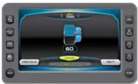
text_image
60 PREVIOUS NEXTTouch to highlight the Pull Type; touch the arrows to change the setting.
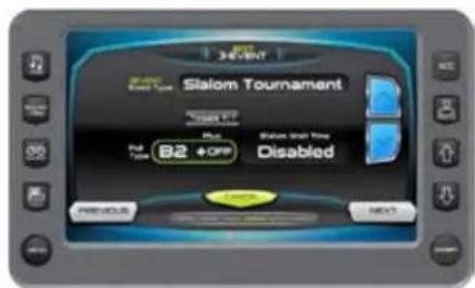
text_image
Slalom Tournament Result Type: 82 +OFF Disabled Previous NEXTTouch the Toggle +/- to set ON or OFF.
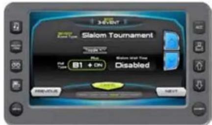
text_image
Slalom Tournament Out Type B1 + On Disabled PREVIOUS NEXTTouch to highlight the Wait Time; touch the arrows to change the setting.
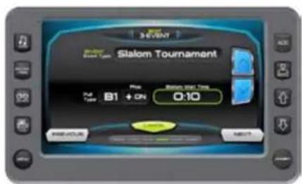
text_image
Slalom Tournament Pain B1 + ON 0:10Set the ballast tanks by touching and sliding the finger up the tank area or by touching the [UP] and [DOWN] arrows alongside the tank area. Touch [NEXT] to continue.
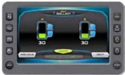
text_image
BALLAST 30 30 PREVIOUS NEXTFinal Save profile or edit screen. Review the Profile settings. Touch [SAVE] to save the profile and return to the Profiles screen with the new profile displayed.
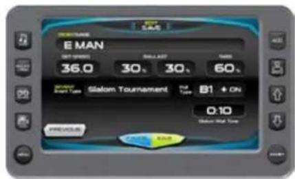
text_image
E MAN 36.0 30, 30, 60, Salam B1 + ON 0:10 Slalom Tournament Salam - Black TampNew rider activates Screen with New name listed above the Activate button. Touch [ACTIVATE] to activate the settings for this profile.
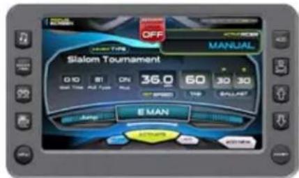
text_image
OFF MANUAL Slalom Tournament 0:10 81 CN 36.0 60 30 30 Sail Top All Top Plus SPEED T40 BALLFAST E MAN Jump AUTO AUTO AUTOOn the 3 Event Screen, everything is activated.

text_image
SET SPEED 8 MAN 0.0 MPH RPM 0 SRT SPECT. 10.0- 16:4PM TO REMAIN DO NOT ALLOW CHANGE EVENT NO CHANGE COURSE NAME B1 FULL TYPE + ONDELETE CURRENT PROFILE
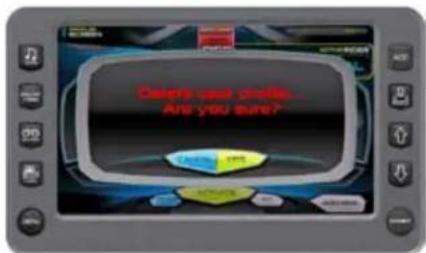
text_image
Deires just emails... Are you sure?Touch [DELETE] to delete the current profile. A confirmation overlay is displayed. Touch [CANCEL] to abort the process and [YES] to confirm delete.
text_image
Profile has been deleted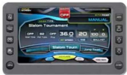
text_image
OFF MANUAL Slalom Tournament OFF 82 OFF 36.0 20 100 0 Start Time Put Tour: Plus 07:45:00 1:10 BALLAST Slalom Tour Jump Touch AVGAR FREE FREETouch [OK] to return to the Profiles screen. Now the Profile screen has no rider profile.
EDIT CURRENT USER
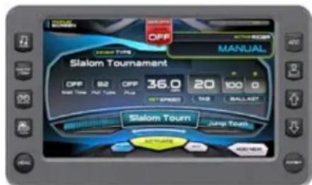
text_image
OFF MANUAL Stalom Tournament OFF B2 OFF 36.0 20 100 0 Start Time: RUN Time: Plus Speed TAG BALLAST Stalom Tourn Jump Touch ACTUATES ADD/MAKE
text_image
BUY NAME EMAN CHANGE NEXTTouch [EDIT] to modify the user profile. Touch [EDIT] to retype the name, touch [NEXT] to continue or [CANCEL] to return to the Profiles Screen.
Follow the same steps as creating a new profile touch [NEXT] to continue to the next screen without change. Remember to click the Save on the final screen to save the changes.
TOURNAMENT EVENTS
The 3 Event screen can be accessed by pressing the Quick Access Key. This feature provides a way to keep a boat within the strict guidelines of the event it is tracking and provide a visual display of the track and the progress of the skier.
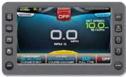
text_image
17.50 SAMS OFF SET SPEED 10.0 MPH RPM G MPH Tournament SCALOM CRAVEE EVENT No Course Active COURSE MANAGER B2 CALL TIME OFFTournament and Training Modes
There are two modes for the 3-Event feature, Tournament and Training. On the 3-Event Screen touch [Change Event] to access the pop-up list.
Tournament Mode Training Mode
Slalom Tournament Slalom Training
Jump Tournament Jump Training
Trick
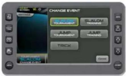
text_image
CHANGE EVENT Tournament SHALON TRADING JUMP Tournament JUMP TRADING TRICK CHANGE EVENT SHALON Tournament SHALON TRADING JUMP Tournament JUMP TRADING TRICK CancelThe Tournament Mode is limited to the set speed of the event. The Training Mode operates like the Tournament Mode without the set speed limitation.
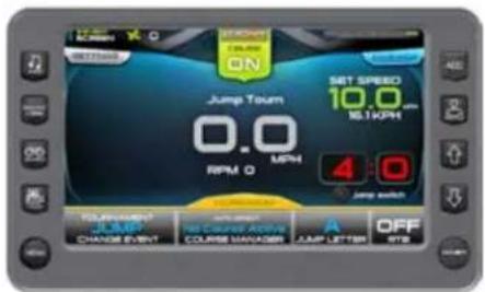
text_image
ON SET SPEED 10.0 16.1KPH 4:0 Jump switch JUMP CHANGE EVENT No Course Active COURSE MANAGER JUMP LETTER OFF STB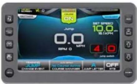
text_image
SPEED ON JUMP 0.0 MPH BPM 0 SET SPEED 10.0 15.1KPH 4.0 Jump switch TEACHING JUMP CHANGE EVERY! AUG FREE No Course Active COURSE MANAGER JUMP LETTER OFF SITESLALOM SCREEN— TOURNAMENT OR TRAINING
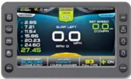
text_image
17:50 OFF 0.60 METHODS ON 2.65 7.21 11.54 15.86 20.23 24.60 27.45 SURF LEFT 0.0 MPH RPM O B3 ON SET SPEED 0.0 0 MPH TELEPHONE ORDER COPY COURSE NAME DUTTERThe screen illustrates the display available when the event being tracked is the Slalom event; the three-event feature is turned on and is in tournament mode. The Touch Commands aid in setting up, controlling and tracking the Slalom event.
Touch Commands Description
Cruise - Touch to turn cruise control ON or OFF. (or press the Quick Access Key from this screen.)
Settings – Select to set the Buzzer Volume, Prop Type, Timing Recap, and Slalom wait time. See Slalom Tournament Settings.

Save New - Select to setup a new ride profile. See Profiles.

Change Event - Touch to select an event from a list.
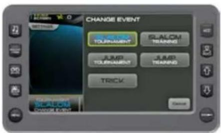
text_image
CHANGE EVENT Tournament SALON Training JUMP Tournament JUMP Training TRICK Cancel
Course Manager – Allows you to map a course. See Course Manager.
Pull Type -Touch to select a pull type from a list.
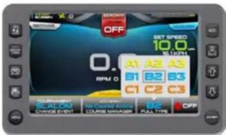
text_image
OFF SET SPEED 10.0 W 11kPH A1 A2 A3 B1 B2 B3 C1 C2 C3 NO PROGRESS SCALOM CHANGE EVENT NO COURSE FORCE COURSE MANAGER B2 FULL TYPE OFF

Plus-Factor - Touch to select ON or OFF from the pop-up. This setting is for additional throttle when entering the first gate.
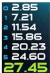
bar
| Category | Value | |---|---| | 0 | 2.85 | | 1 | 7.21 | | 2 | 11.54 | | 3 | 15.86 | | 4 | 20.23 | | 5 | 24.60 | | 6 | 27.45 |Event Times -Display the event times as the skier passes the mapped points. (Touch the numbers to view the previously recorded times; Timing Recap.)
SLALOM SETTINGS- TOURNAMENT OR TRAINING
On the 3 Event Screen, touch the Settings touch command to access the pop-up list. Touch each option to view or change the setting. When available, touch the arrows to change the setting.
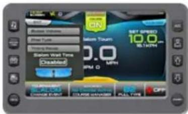
text_image
Balance Volume Steel Type Tracking Pressure Stolen Wait Time Disabled ON Stolen Tour SET SPRED 10.0 W.LT/PM RPM Q MPH TURSDUCT WHIP CHANGE EVELP STORAGE WTRIPLY SELL TIME OFFTouch [Settings]. On the Pop-up, touch the arrows to change the Slalom Wait Time.
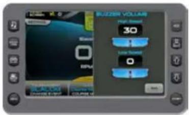
text_image
BUZZER VOLUME High Speed 30 Low Speed 0 OKTouch [Settings]. Touch [Buzzer Volume]. On the Pop-up, touch the arrows to turn Buzzer Volume UP or DOWN.
Touch [Exit] to return to close the pop-up.
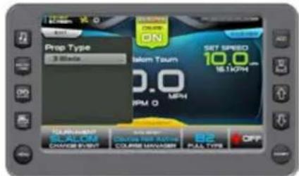
text_image
Prop Type 3.000 ON Takom Toun 10.0 RPM O SET SPEED 10.0 15.1KPM MANUWARE SCL ALUM CHANGE EVENT COURSE MANAGER B2 PAS TYPE OFFTouch [Exit] to return to close the pop-up. Touch [Settings]. Touch [Prop Type]. On the Pop-up, touch to change from 3 blade or 4 blade.
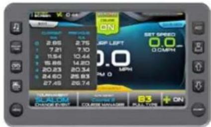
text_image
2.05 7.21 11.54 15.86 20.23 24.60 27.45 2.75 7.10 10.44 14.20 20.34 25.93 26.74 SET SPEED 0.0 0.0 MPH B3 + ON ORANGE EVENT COURSE MANAGER PLAY TOWNTouch [Settings]. Touch [Timing Recap]. The pop-up displays current and previous event times.
COURSE MANAGER- ALL SLALOM AND JUMPING EVENTS
On the 3 Event screen, touch the [Course Manager] in the bottom of the screen to start mapping a course.
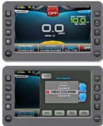
text_image
OFF SET SPEED 10.0 MPH 0 RUM TRAULANT BALOM CHANGE EVENT AS CHAPES WORKS COURSE FLAGERS PULL TYPE OFF NOT INSPRING Course 1 Course 2 NEW COURSE Course 3 REVIEW CREAM CONTROLTouch the arrows to select a course that is not mapped. Touch [Map Course].
NOTE: Additional Details on Course List: The blue lettering above the course list displays the mapped information for the course selected. Always highlight a course on the list page before mapping a new course. When mapping a course, the program assigns the mapping to whatever name is highlights on the course list. For example, if Course1 was previously mapped and is highlighted when a new course is mapped, the new mapping will overwrite the original.
Touch the arrows to select a course type: Jump, Slalom 4-Buoy or Slalom 8-Buoy. Touch [Continue].
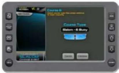
text_image
Course 6 Slalom - 6 Buzy Course Type Slalom - 6 Buzy Cancel CancelAllow the program time to load.
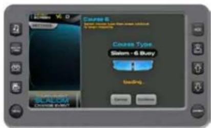
text_image
Course 6 Salem - 6 Buzy Trading Eating Downdie AutoPress the [Start Gate] to begin Mapping.
NOTE: For Slalom, press the [Start Gate] button when the GPS puck crosses the start gate.
For Jump, press the [Start Gate] button when the ski pylon crosses the start gate.
If necessary, touch [Cancel] to cancel the current mapping and return to the course list.
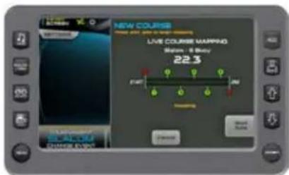
text_image
NEW COURSE LIVE COURSE MAPPING Balance - B Baby 22.3 14:47 20:00 Start EndPress the [End Gate] to complete Mapping.
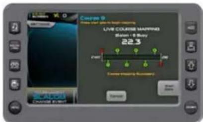
text_image
Couple 9 Live Course Tracking Bamen / B Buy 22.3 Live Course Tracking Bamen / B Buy 22.3 Bamen / B Buy Crown Tracking Tracking Crown Tracking Tracking Crown Tracking Tracking Crown Tracking Tracking Crown Tracking Tracking Crown Tracking Tracking Crown Tracking Tracking Crown Tracking Tracking Crown Tracking Tracking Crown Tracking Tracking Crown Tracking Tracking Crown Tracking Tracking Crown Tracking Tracking Crown Tracking Tracking Crown Tracking Tracking Crown Tracking Tracking Crown Tracking Tracking Crown Tracking Tracking Crown Tracking Tracking Crown Tracking Tracking Crown Tracking Track Crown Track Track Crown Track Track Crown Track Track Crown Track Track Crown Track Track Crown Track Track Crown Track Track Crown Track Track Crown Track Track Crown Track Track Crown Track Track Crown Track Track Crown Track Track Crown Track Track Crown Track Track Crown Track Track Crown Track Track Crown Track Track Crown Track Track Crown Track Track Crown TrailCourse Mapping Successful will appear on the screen.
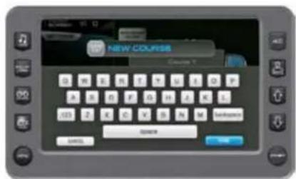
text_image
NEW COURSE Course 1 0 1 2 3 4 5 6 7 8 9 10 11 12 13 14 15 16 17 18 19 20 21 22 23 24 25 26 27 28 29 30 31 32 33 34 35 36 37 38 39 40 105 2 X C V S N M Settings OK Cancel NextType the name of the course. Touch [Done]. This saved your changes. The new name is highlighted. Touch [Done].
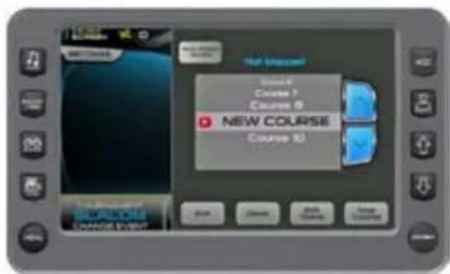
text_image
Hot Microsoft Course 1 Course 2 NEW COURSE Course IDNOTE: Additional Options on the Course List pop-up.
- Auto Detect – Touch to select ON or OFF.
Auto Detect ON-the display automatically selects the nearest mapped course, based on the longitude/latitude that is the same event type the user is in (slalom or jump).
Auto Detect OFF-The user must select a course before running it.
- Edit Name – Touch to go back and edit a previously saved course.
- Map Course – Touch to map another course.
- Exit - touch to return to the 3 Event screen.
- List of Courses - Touch UP and DOWN arrows to scroll the list and choose a course.
JUMP SCREEN- TOURNAMENT OR TRAINING
The screen illustrates the display available when the event is Jump Tournament; the three-event features are in tournament mode and ready for settings. Use the Touch Commands in setting up, controlling and tracking the Jump event.
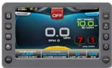
text_image
OFF 0.0 RPM D ON SET SPEED 10.0 16.12GHz 7:1 Jump switch Take Mezzles? ON/OFF ON/OFF ON/OFF ON/OFF ON/OFF ON/OFF ON/OFF ON/OFF ON/OFF ON/OFF ON/OFF ON/OFF ON/OFF ON/OFF ON/OFF ON/OFF ON/OFF ON/OFF ON/OFF ON/OFF ON/OFF ON/OFF ON/OFF ON/OFF ON/OFF ON/OFFTouch Commands Description
Cruise - Touch to turn cruise control ON or OFF. (or press the Quick Access Key from this screen.)

Settings - Select to set the Buzzer Volume, Prop Type, Timing Recap, and Jump Switch Timeout.
Save New - Select to setup a new rider profile. See Profiles.

Change Event - Touch to select an event from a list.
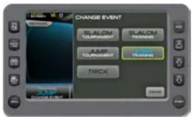
text_image
CHANGE EVENT SLALOM TOLERMENT SLALOM TRAVES RAMP TOLERMENT CORN TRAVES TRACK A-AMP DRAGON EVENT
Course Manager - Allows you to map a course. See Course Manager.

Jump Letter - Touch to select a Jump Letter, Weight, and Distance using the arrows to change the values. Touch [Accept] to save or [Cancel] to close pop-up.
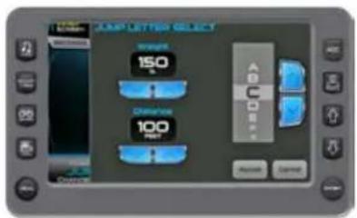
text_image
JUMP LETTER SELECT Product 150 Order 100 Part A B C D Reset Cancel
RTB - Touch to select ON or OFF from the pop-up.
Event Times - Display the event times as the skier passes the mapped points. (Touch the numbers to view the previously recorded times; Timing Recap.)
JUMP SETTINGS— TOURNAMENT OR TRAINING
On the 3 Event Screen, touch the Settings touch command to access the pop-up list. Touch each option to view or change the
setting. When available, touch the arrows to change the setting. Touch [Exit] to close the pop-up.\
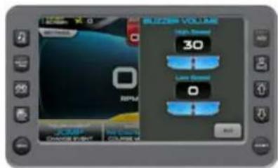
text_image
RPMU High Speed 30 Low Speed 0 Control Panel Control PanelTouch [Settings]. Touch [Buzzer Volume]. On the Pop-up, touch the arrows to set a value at high speed and low speed.
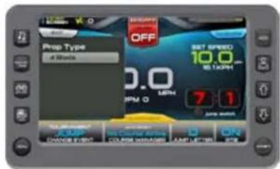
text_image
Prop Type 4 Stocks OFF SET SPEED 10.0 5:30PM 0.0 RPM 0 7:1 JIME MATH SUNTER RUN ON DANCE END COOPERATION ON LIME ONTouch [Settings]. Touch [Prop Type]. On the Pop-up, touch to set at 3 blade or 4 blade.
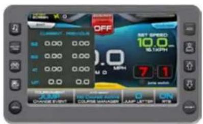
text_image
OFF SET SPEED 10.0 6:30PM 7:1 ON TIME CHANGE EVENT COURSE MANAGER JUMP LETTER ONTouch [Settings]. Touch [Timing Recap]. The pop-up displays current and previous event times.
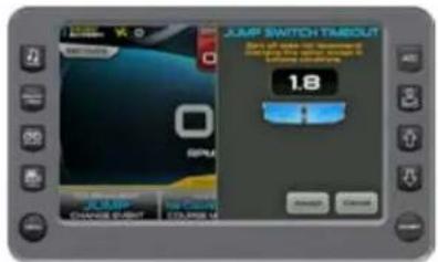
text_image
JUMP SWITCH TIMEOUT 1.8 CHANGE ORDER 10:00 AM 24:00 PM START CancelTouch [Settings]. Touch [Jump Switch Timeout]. On the Pop-up, touch the arrows to change the value.
NOTE: ZeroOff recommends keeping the default value of 1.8, (only changing in extreme conditions).
TRICK SCREEN
The screen illustrates the display available when the event is Trick Tournament; the three-event features are in tournament mode and ready for settings. Use the Touch Commands in setting up, controlling and tracking the Trick event.
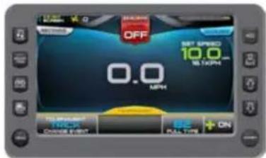
text_image
OFF 0.0 MPH SET SPID 10.0 M L KPM TO PRODUED TRACKS ON FULL TIPS + ONTouch Commands Description
text_image
ZERO OFF CRUISE ON ZERO OFF CRUISE OFF SETTINGS SAVE NEW TOURNAMENT TRICK CHANGE EVENTCruise - Touch to turn cruise control ON or OFF (or press the Quick Access Key from this screen.)
Settings - Select to set the Buzzer Volume, Prop Type, and River Mode.
Save New - Select to setup a new rider profile. See Profiles.
Change Event – Touch to select an event from a list.
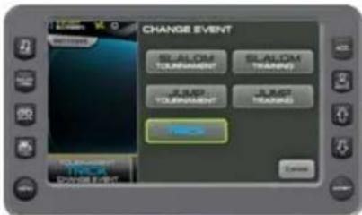
text_image
CHANGE EVENT RANDOM TURRANGS RANDOM TURRANGS JMP TURRANGS JMP TURRANGS BACK To account CHANGE EVENTCourse Manager - Allows you to map a course. See Course Manager.
AUTO DETECT
No Course Active
COURSE MANAGER

Pull Type -Touch to select a Pull Type on the pop-up.
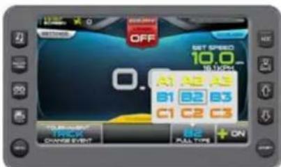
text_image
OFF SET SPEED 10.0 16:00pm A B C B1 B2 B3 C1 C2 C3 "ON TIME" ON ON ON ON ON ON ON
Plus-Factor - Touch to select ON or OFF from the pop-up. In the ON position, the system will react sooner to both increase and decrease in speed deviation. Used for
trick setting or additional throttle when entering the first gate.
TRICK SETTINGS- TOURNAMENT OR TRAINING
On the 3 Event Screen, touch the Settings touch command to access the pop-up list. Touch each option to view or change the setting. When available, touch
the arrows to change the setting. Touch [Exit] to close the pop-up.
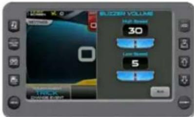
text_image
BLUZER VOLUME High Speed 30 Low Speed 5 StartTouch [Settings]. Touch [Buzzer Volume]. On the Pop-up, touch the arrows to set a value at high speed and low speed.
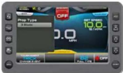
text_image
Prop Type 3 Mbps OFF 0.0 MPN SET SPEED 10.0 5 LTR/N Temperature CHANGE OUT OFF BAL TONE OFFTouch [Settings]. Touch [Prop Type]. On the Pop-up, touch to set at 3 blade or 4 blade.
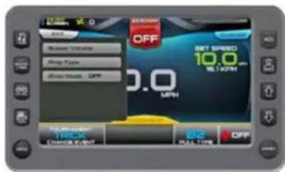
text_image
OFF Maxim Volume Amp Type Drive Mode: OFF SET SPEED 10.0 MPH OFF 10.0 DANCE TEST OFF ROLL TIMETouch [Settings]. Touch [River Mode] to select ON or OFF. With River Mode ON, touch to set the River Dir Offset UP and DOWN values using the arrows.
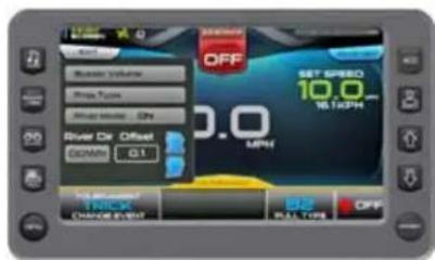
text_image
OFF SET SPEED 10.0 METH 0.0 MPN OFF Speed Volume Prop Type Air Speed: 500 River Dir. Offset Domain: 0.1 Top-down/- FIRE CHANGE EVENT FULL TONESETTINGS MENU
The Settings Menu screen can be accessed by pressing the Quick Access Key. The following settings are available:

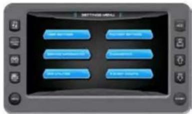
text_image
SETTINGS MENU New Service Access Service Security Service Security Service New Service New SecurityTouch Commands Description
User Settings – Allows you to customize the display options for ambient light and brightness, set US or metric units Tab, Ballast,
and other settings.
Service Information – Provides information about the software version, dealer, oil changes and dealer services.
GPS Utilities – Displays Satellite Status and Time and Position Setup options.
Factory Settings - Displays boat model, center tab, surf tabs and depth transducer. A dealer code is required to access.
Diagnostics – Displays Engine, PDM, and 3 Event Diagnostics including a list of fault codes and descriptions; on some screens, will be shown.
3-Event Charts - Displays reference tables of the Slalom Timing Tolerances and Jump Timing Tolerances.
USER SETTINGS
On the Settings Menu, touch the User Settings touch command to access the first of two user settings screens. Touch the field following the option to change the available, touch the option to highlight it change the setting. Touch [Next] to access Back] to return.
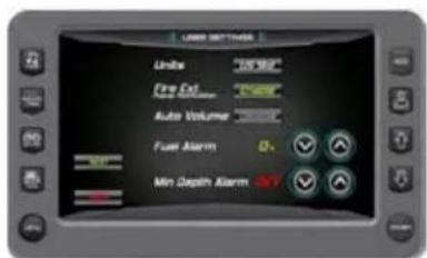
text_image
USB SETTING Under "0.012" Fire Out Auto Volume Fuel Alarm 0 Min Depth Alarm
text_image
LIGHT DIMENSIONS Gray Brightness High Precision Size Brightness-Ray Size Brightness Dark APS Medium Noise Noise Level Noise LevelDescription of Options
Touch Commands Description
Units US Standard (US Std) or Metric
Fire Extinguisher Enable (Pop-up) or Disable (Pop-up)
Auto Volume Enable or Disable
Fuel Alarm alarm Sets the percent of fuel left in tank to deploy the
Min Depth Alarm ON or OFF
Day Brightness Sets the screen brightness for daylight Night Brightness Sets the screen brightness for nighttime Gauge Brightness Sets the gauge brightness for daylight Day
Gauge Brightness Sets the gauge brightness for nighttime Night
Tab Settings Page: Controls the tab positions for two trim tabs on the boat. See Tab Settings.
Ballast Settings Controls the ballast fill and drain times. See Ballast Page Setting.
Connects to GPS YES = There is no Paddle Wheel Offset field. NO = A Paddle Wheel Offset field is provided.
Paddle Wheel Offset Sets the paddle wheel offset. (Only available if GPS is not connected.)
TAB SETTINGS (SPEED, AUTO, POSITION)
On the User Settings Screen, touch the Tab Settings touch command to access the Tab Settings screen. The Auto Tab Settings provide the user with the opportunity to control the tab positions for two trim tabs on the boat. The following can be controlled through these settings:
- Two Speed settings
- Trim Tab positions
• Turn Auto Limits ON and OFF - Set the Auto Launch timing
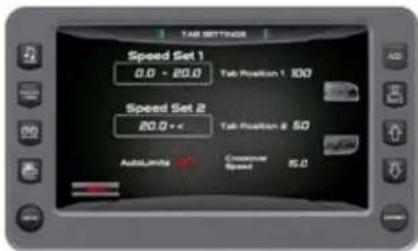
text_image
TAB SETTINGS Speed Set 1 0.0 - 20.0 Tab Position 1 300 Speed Set 2 20.0 + c Tab Position 2 50 AutoLima → Consecutive Speed 8.0BALLAST SETTINGS (TANK FILL/DRAIN TIMES)
Ballast Settings
In the User Settings Screen, touch the Ballast Settings key to access the Ballast Settings
screen. This screen provides the ability


to control the ballast fill and drain times. Touch the Next Setting key to move the triangle under a setting and touch the arrows
to change the setting.
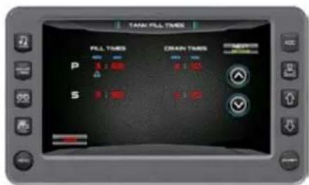
text_image
TANK FILL TIMES PILL TIMES CRAIN TIMES P 1:50 2:50 S 3:50 4:50SERVICE INFORMATION
On the Settings Menu, touch the Service Information touch command to access the Service Information. This set of screens display software information and allows the dealer to reset the engine oil change intervals and the dealer service schedule.
NOTE: The Dealer Service Reset requires a dealer code to be entered before the gaining access to the screens.
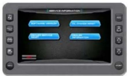
text_image
SERVICE INFORMATION Service Information Service Status Service Relationship Service DescriptionTouch Commands Description

Software Version - Displays part numbers and versions for the application, software, operating system and more.
Dealer Service Reset – The dealer sets the number of engine running hours between servicing intervals at which time an alert will be displayed to the to the boat operator.
Oil Change Reset - Touch to reset for the next oil change alert. (The service intervals are predetermined and set by the dealer)
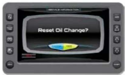
text_image
Reset Oil Change?
Dealer Information – Provides your dealers contact information such as a phone number.
GPS UTILITIES
On the Settings Menu, touch the GPS Utilities touch command to access the GPS Utilities screen. The GPS Utilities include the Satellite Status and the Time and Position Setup.
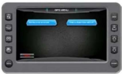
text_image
IBM MENU Microsoft Teams My Computer will get itTouch Commands Description

GPS Status - Displays the location of the satellites.
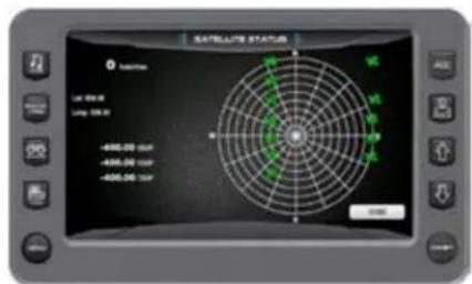
text_image
Satellite Status Satellite LIF 98.00 LIF 105.00 -6995.00 0x1 -6995.00 0x2 -6995.00 0x3 -6995.00 0x4
Position Format Selection - Feature allows you to define the amount of detail to display for longitude and latitude information on the GPS map.
Time Setup Parameters - This is used to select correct time zone and clock mode for either 12-hour or 24-hour time formats. You can also enable DST (Daylight Savings Time) by using the PLUS/MINUS soft keys to select the box.
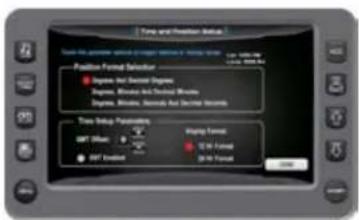
text_image
Time and Position Setup Time to provide available or better version of the system Position Format Settings • Dimensions And Decimal Dimensions • Dimensions And Decimal Dimensions • Dimensions And Decimal Dimensions Time Setup Parameters 0.01 (Max) 0.02 (Min) 0.03 (Max) 0.04 (Min) 0.05 (Max) 0.06 (Min) 0.07 (Max) 0.08 (Min) 0.09 (Max) 0.10 (Min) 0.11 (Max) 0.12 (Min) 0.13 (Max) 0.14 (Min) 0.15 (Max) 0.16 (Min) 0.17 (Max) 0.18 (Min) 0.19 (Max) 0.20 (Min) 0.21 (Max) 0.22 (Min) 0.23 (Max) 0.24 (Min) 0.25 (Max) 0.26 (Min) 0.27 (Max) 0.28 (Min) 0.29 (Max) 0.30 (Min) 0.31 (Max) 0.32 (Min) 0.33 (Max) 0.34 (Min) 0.35 (Max) 0.36 (Min) 0.37 (Max) 0.38 (Min) 0.39 (Max) 0.40 (Min) 0.41 (Max) 0.42 (Min) 0.43 (Max) 0.44 (Min) 0.45 (Max) 0.46 (Min) 0.47 (Max) 0.48 (Min) 0.49 (Max) 0.50 (Min) 0.51 (Max) 0.52 (Min) 0.53 (Max) 0.54 (Min) 0.55 (Max) 0.56 (Min) 0.57 (Max) 0.58 (Min) 0.59 (Max) 0.60 (Min) 0.61 (Max) 0.62 (Min) 0.63 (Max) 0.64 (Min) 0.65 (Max) 0.66 (Min) 0.67 (Max) 0.68 (Min) 0.69 (Max) 0.70 (Min) 0.71 (Max) 0.72 (Min) 0.73 (Max) 0.74 (Min) 0.75 (Max) 0.76 (Min) 0.77 (Max) 0.78 (Min) 0.79 (Max) 0.80 (Min) 0.81 (Max) 0.82 (Min) 0.83 (Max) 0.84 (Min) 0.85 (Max) 0.86 (Min) 0.87 (Max) 0.88 (Min) 0.89 (Max) 0.90 (Min) 0.91 (Max) 0.92 (Min) 0.93 (Max) 0.94 (Min) 0.95 (Max) 0.96 (Min) 0.97 (Max) 0.98 (Min) 0.99 (Max 1) Time and Position Settings • Dimensions And Decimal Dimensions • Dimensions And Decimal Dimensions • Dimensions And Decimal Dimensions • Dimensions And Decimal Dimensions • Dimensions And Decimal Dimensions • Dimensions And Decimal Dimensions • Dimensions And Decimal Dimensions • Dimensions And Decimal Dimensions • Dimensions And Decimal Dimensions • Dimensions And Decimal Dimensions • Dimensions And Decimal Dimensions • Dimensions And Decimal Dimensions • Dimensions And Decimal Dimensions • Dimensions And Decimal Dimensions • Dimensions And Decimal Dimensions • Dimensions And Decimal Dimensions • Dimensions And Decimal Dimensions • Dimensions and Horizontal • Dimensions and Horizontal • Dimensions and Horizontal • Dimensions and Horizontal • Dimensions and Horizontal • Dimensions and Horizontal • Dimensions and Horizontal • Dimensions and Horizontal • Dimensions and Horizontal • Dimensions and Horizontal • Dimensions and Horizontal • Dimensions and Horizontal • Dimensions and Horizontal • Dimensions and Horizontal • Dimensions and Horizontal • Dimensions and Horizontal • Dimensions and Horizontal • Dimensions and Horizontal • Dimensions and Horizontal • Dimensions and Horizontal • Dimensions and Vertical • Dimensions and Vertical • Dimensions and Vertical • Dimensions and Vertical • Dimensions and Vertical • Dimensions and Vertical • Dimensions and Vertical • Dimensions and Vertical • Dimensions and Vertical • Dimensions and Vertical • Dimensions and Vertical • Dimensions and Vertical • Dimensions and Vertical • Dimensions and Vertical • Dimensions and Vertical • Dimensions and Vertical • Dimensions and Vertical • Dimensions and Vertical • Dimensions and Vertical • Dimensions and Vertical • Dimensions andVertical • Dimensions andVertical • Dimensions andVertical • Dimensions andVertical • Dimensions andVertical • Dimensions andVertical • Dimensions andVertical • Dimensions andVertical • Dimensions andVertical • Dimensions andVertical • Dimensions andVertical • Dimensions andVertical • Dimensions andVertical • Dimensions andVertical • Dimensions andVertical • Dimensions andVertical • Dimensions andVertical • Dimensions andVertical • Dimensions andVertical • Dimensions andVertical • Dimensions andHorizontal • Dimensions andVertical • Dimensions andVertical • Dimensions andVerticalFACTORY SETTINGS

On the Settings Menu, touch the Factory Settings touch command to access the Factory Settings screen. A Dealer code is required to access this screen.
text_image
FACTORY SETTINGS Factory settings must be a dealer code. If changes are needed, please contact your dealer. DEALER CODEDIAGNOSTICS
On the Settings Menu, touch the Diagnostics touch command to access the Diagnostics screen.
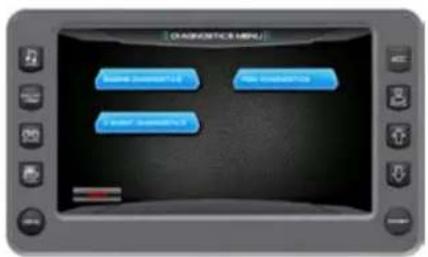
text_image
CAGNOSTIC MPU Base := 0.1 High := 0.2 Low := 0.3When choosing this selection, the display will query the engine(s) ECU, as illustrated following, and provide feedback.
Touch Commands Description

Engine Diagnostics - Displays feedback on any diagnostic codes that have been activated and stored in the
ECU for service needs.
3 Event Diagnostics - Displays any 3 Event fault codes that have been activated and allows you to clear faults.
PDM Diagnostics – Displays short circuits, open circuit, over current, in/out of range, and faults within the system outputs, switch inputs, analog inputs, and CAN communication.
ENGINE DIAGNOSTICS
On the Diagnostics Menu, touch the Engine Diagnostics touch command to access the Engine Diagnostic screen.
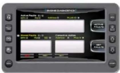
text_image
RANGE DIAGNOSTICS Active Paunts 0/0 OFF 0 PAUT 000440 PLUG 5 Active Paunts Shared Paunts 0/0 OFF 0 PAUT 000 Conservative Action Address 0 Plug 0 SBT PAULTSThe following is a list of field definitions contained on the ENGINE DIAGNOSTICS screen:
Active Faults/Stored Faults
Shows the number of active faults and which fault number is currently being displayed. To advance to the next fault, touch [NEXT] and [PREV] to go back to the previous fault. Touching [BACK] returns to the Settings Menu.
- SPN - "Suspect Parameter Number" - fault code if not translated into text by the display, see the engine manufacturer's literature for the definition of the SPN number.
- FMI - "Failure Mode Indicator" - fault code The FMI is defined by SAE J1939. If not translated into text, see the SAE standard, or the engine manufacturer's literature.
- Description Field – Most common SPN's and FMI's have text for the description stored in the display. If there is no text, then this SPN and FMI must be defined by referring to the engine manufacturer, or the SAE J1939 standard.
NOTE: This field is only used with certain brands and models of engines.
Corrective Action (Suggested action for correction):
Get Faults
Touching [Get Faults] queries the engine(s) ECU for feedback on diagnostic codes that have been activated and stored in the ECU for service needs.
3 EVENT DIAGNOSTICS
On the Diagnostics Menu, touch the 3 Event Diagnostics touch command to access the 3 Event Diagnostics screen.
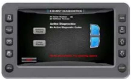
text_image
3 EVENT DIAGNOSTICS All serve: Numbness 20 All Software: Numbness Active Diagnosis No Active Diagnostics Codes Diagnostic Tools Diagnostic Tools to determine codePDM DIAGNOSTICS
On the Diagnostics Menu, touch the PDM Diagnostics touch command to access the PDM Diagnostics screen.

text_image
PDM DIAGNOSTICS ■ Stream Analysis - Rating 10% of Range ■ Stream Data - Comparison ■ Stream Data - In Range OUTPUTS Number High Number Low Number Close Number Light Number Medium Number Low Number Close Number Light Number Medium Number Low Number Close Number Light SIMTECH INPUTS Size: 0.0000 mm Peak: 0.0000 mm Peak Value: 0.0000 mm Peak Angle: 0° AMUSE INPUTS Peak Amplitude Response Peak Vertical Response All Response3-EVENT CHARTS
On the Settings Menu screen, touch the 3 Event Touch Command to access the 3-Event Charts screen. The charts display reference tables of the Slalom Timing Tolerances and Jump Timing Tolerances.
IMPORTANT: Use the 3-Event Charts for reference only. The charts will not reflect any changes, should a change occur in the rule book. We suggest periodically verifying the charts with the current rule book.
Touch [More] to view the next page.
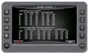
text_image
JULY 19TH: Music & TV Date: July 19th, 2005 Time: 14:00 AM Venue: June 19th Date: July 19th Venue: June 19th Date: July 19th JULY 19TH: Music & TV Date: July 19th, 2005 Time: June 19th Venue: June 19th Date: July 19th JULY 19TH: Music & TV Date: July 19th, 2005 Time: June 19th Venue: June 19th Date: July 19thTouch [Back] to go back one page. Touch any Quick Access Key to exit.
text_image
ASSEMBLIC CHARTS 100% 200% 300% 400% 500% 600% 700% 800% 900% 1000%TROUBLESHOOTING
Display appears not to work or doesn't come ON.
- Display could be in sleep mode. Touch a key on the keypad to activate the display.
- Check for loose connections at battery and display unit.
- Check for reversed polarity on the power connections.
- Verify battery has a minimum voltage of 6 volts.
Display resets or goes OFF when starting engine.
- Check display supply wires are connected properly to battery.
- Verify battery is charged properly.
- Check battery for efficient starter current.
Display has no back light.
Contact your MasterCraft service center.
Display has no keypad back light.
Contact your MasterCraft service center.

natural_image
Two women relaxing in the water, one smiling and the other laughing, under a partly cloudy sky (no text or symbols visible)NXT OPERATIONS
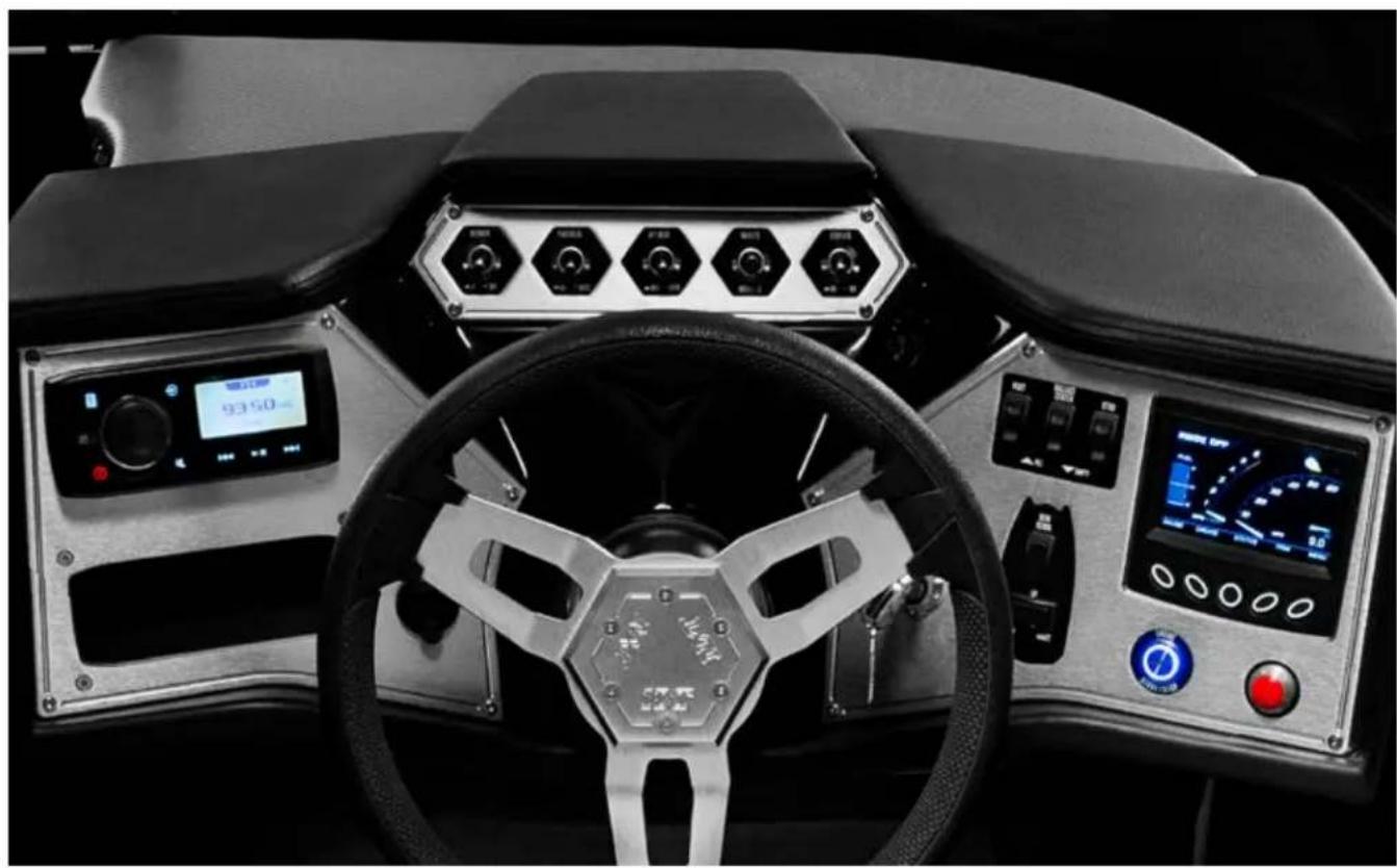
natural_image
Interior view of a car dashboard with steering wheel, digital displays, and control panels (no visible text or symbols)PORT SIDE OF DASH
A = Fusion RA 205 AM/FM stereo system
(where equipped) with four (4) 6.8" JL Audio MX-Series speakers. (See separate, accompanying owners manual from the manufacturer for details regarding operation and care.)
B = 12-volt receptacle. Note that any item plugged into the 12-volt receptacle draws power from the battery(ies). Depending on the item, long term use without the boat engine turned ON could result in excessive drain on the system, affecting the ability to start the engine.
C = USB/Auxiliary input.
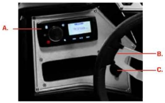
text_image
A. B. C.Top Center of Dash

text_image
D. E. F. G. H.D = Blower switch. A two-position switch activates the engine box ventilation blower. Push the toggle switch UP to turn the blower ON.
NOTE: The blower must operate for a minimum of four (4) minutes before starting the engine at any time.
The blower must also be operated during idle and slow-speed running, but is not necessary during cruising speed.

DANGER
To prevent a possible explosion, operate the blower for at least four (4) minutes before starting the engine and always when at idle or slow-running speed. Explosive gasoline and/or battery fumes may be present in the engine compartment. Failure to operate the blower as instructed may cause improper ventilation of the boat engine and bilge areas, and fuel vapors can accumulate in this area, causing a fire or explosion which may result in serious injury or death!
E = Forward bilge pump.
F = Aft bilge pump. The bilge pumps will be in the automatic mode when the ignition key is turned ON. The manual and automatic bilge discharge system is never completely OFF. When in the automatic (default) position, a sensor alerts the system to discharge water from the bilge area. Boat opera-tors are advised to leave the switch in the automatic position, unless there appears to be excess water in the bilge. In that event, the bilge pump can be manually activated by turning the bilge pump switch to the manual ON position. Return the switch to the automatic position when finished emptying the bilge. Leaving the switch in manual mode can result in damage to the pump and may not be covered by warranty.

CAUTION
Failure to leave the bilge pump switches in AUTOMATIC mode can result in damage to the bilge pumps. The pumps will not shut OFF while in the MANUAL mode until the operator turns them OFF. Such damage is not covered under warranty. Malfunctioning pumps or pumps that do not work at all can result in excess water in the bilge, and eventually into the deck. Over time, this could result in sinking of the boat. Such damage is not covered under warranty.
G = Navigation/Anchor lights.
- Push the toggle switch UP to turn the lights ON.
- Return the toggle switch to CENTER (neutral) to turn the light OFF.
- Push the toggle switch DOWN to turn the anchor lights ON.

WARNING
MasterCraft boats are designed for activities that should be conducted during daylight with good visibility. When operating at night or in limited visibility, turn on the navigation lights and slow down. In limited visibility it is difficult to see and interpret the running lights of other boats, particularly with lights on-shore that are in the background. Operating at slower speeds gives you the opportunity to see and be seen by others. Weather conditions during daylight may also result in the need to run or anchor with the lights on. When circumstances require the operation of your MasterCraft boat at night or in limited visibility, activate the navigation lights, ensure that they are functioning and SLOW DOWN. Maintain a close watch for the navigation lights of other vessels and objects in the water. Failure to do so may result in serious injury. See the Visual Assistance section of the Boat Operations chapter.
H = Courtesy lights. This two-position toggle switch is pushed UP to turn ON, and DOWN to turn OFF.
STARBOARD SIDE OF DASH
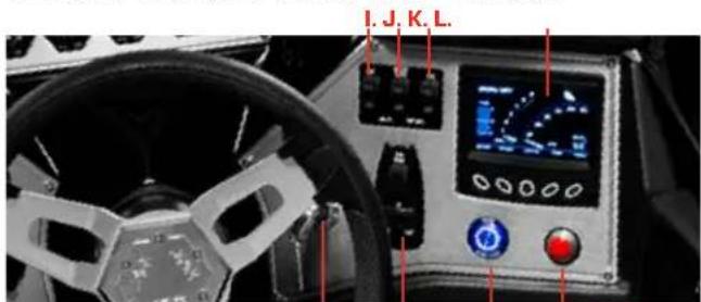
text_image
I. J. K. L.P.O.N.M.
Tsunami Pump System
I = Ballast port tank switch.
J = Ballast center tank switch.
K = Ballast starboard tank switch.
The ballast tanks are filled and emptied by pressing the switches, which are clearly marked by tank designation above the three-position switches. To fill, press the appropriate switch UP; to empty, press the appropriate switch DOWN. The center (or neutral) position is OFF and the pumps are inactive.
IMPORTANT NOTE: These switch controls and pumps do not operate AUTOMATICALLY! It is important for operators to return the switches to the center (or neutral) position after filling or emptying tanks
It is possible for operators to be aware when tanks are full as overflow will exit the tanks through the overflow vents. When emptying, operators should pay attention to the vents. When the tanks are empty, water will cease to come out the vents. (See Pages 10-2 and 10-3 of this NXT20 supplement for the approximate locations of the vents.)

CAUTION
Failure to maintain the ballast switches in the center or neutral position at all times other than when purposely filling or emptying the system(s) will result in permanent damage to the tsunami (ballast) pumps. This is not covered under warranty! In the event of the failure of the tsunami ballast pumps, the inability to empty the tank(s) of all water may result in more serious issues such as unanticipated effects on boat maneuverability, preventing the boat from being loaded on a trailer for towing and/or instability during towing of the boat due to the increased weight from the filled tank.
L = NXT Video Screen. See following section for information regarding operation.
M = Ignition Key ON/OFF
O = START/STOP BUTTON.
NXT20 boats are equipped with a removable ignition key. Its purpose is for safety and security. The key should be inserted prior to
starting an outing, and removed at the conclusion. This is intended to prevent theft or unapproved use of the boat.
The process for starting the boat is:
- Insert the key and turn to the right (starboard). This turns ON the electrical system and prompts the battery(ies) to provide power.
- Turn the blower ON and allow it to run for at least four (4) minutes before starting the engine.
- Momentarily press the ENGINE START-STOP button.
- Momentarily press the ENGINE START-STOP button to turn OFF the engine.
NOTE: This button affects only the engine. The electrical system will continue to operate as long as the key is turned. If the key is left turned on after the outing, it will eventually run down the battery(ies) and the engine, and all systems will not start as a result.
At the conclusion of the outing, turn the key OFF and remove from the key slot. Also, shut OFF the battery switch. Doing so will ensure that you have turned OFF the electrical system, and prevent others from starting or running the boat. Note that shutting OFF the key but failing to also turn OFF the battery switch will result in the electrical charge to the battery or batteries continuing to drain. Such drain will, in time, render the batteries unable to start the engine or run any electrical components on the boat. As noted elsewhere in this Owner's Manual, a dead battery could cause boaters to become stranded.
N = Attitude Adjustment Plate and NXT Wake Shaping Devices.
The Attitude Adjustment Plate has been designed to improve the overall attitude of a boat. If used properly, the plate will improve the ride, reduce drag, increase speed and improve the fuel efficiency of the boat.
The plate is mounted with the actuator on the transom of the boat. When the plate is lowered, the water flow is redirected, creating an upward force at the stern of the boat. When the stern rises, the bow will lower.
Since the actuator that maneuvers the plate is electromechanical, it provides an immediate response at the touch of the switch. The switch adjustments are based on the position of the bow, and are designed in that manner to minimize the guesswork while underway.
Press the switch DOWN to lower the bow. Press the switch UP to raise the bow.
Since our models have different weights, lengths, speed and performance, it will take some practice for the operator to understand how the boat reacts with the attitude adjustment plate installed. The plates will allow your boat to get on plane faster and continue planing at lower speeds. This will improve visibility and the overall safety of the boat.
When making adjustments with the attitude adjustment plates, use short momentary taps of the switch. Continued practice will help you become familiar with how the plates perform.
NXT Wake Shaping Device switches: Press the LEFT side of the three-position switch to allow the boat to roll left. Press the RIGHT side of the three-position switch to allow the boat to roll right. Placing the switch in the center or neutral position maintains the devices in equal position, ceasing the roll to one side or the other.
Maneuvering a boat with the wake shaping devices deployed requires practice to master. Initial times running with either deployment should be done at low speed and with plenty of room. This is critical to learning how the devices affect control and maneuverability.

Electromechanical actuators provide an instant response. When making adjustments, use short momentary taps of the switch.
To raise all three (3) devices (the two [2] wake shaping devices and the one [1] attitude adjustment plate): press and hold the switch until the attitude plate equals 0% (zero percent). Release, and then press again to raise the wake shaping devices to 0% (zero percent). To raise one side, press the opposite side, i.e., to raise the right (starboard) side, press the left (port) side of the wake shaping device switch.
Special Conditions
Head Sea: Lower the plate by tapping slightly DOWN. This will bring the bow down while maintaining speed. This also allows the hull of the boat to absorb the impact of the waves. This adjustment will result in a more efficient and smoother ride. Changes should be made in small increments to ensure maintaining control of the boat.
Following Sea: Make sure the plate is fully retracted by pressing UP. This will bring the plate up to a fully retracted position, decreasing lift in the stern and allowing the bow to rise. If the plate is deployed, the bow may dig.
Shallow Water/Hole Shot: Lower the plate completely by pressing DOWN. This provides lift in the stern of the boat and will keep the bow down. As you throttle up and speed increases, raise the tab by pressing UP.
Uneven Load: If one side of the boat is higher than the other while running, press DOWN on the switch on that side. This will lower the tab on the listing side (low side) to bring the boat level.
Porpoising: To stop porpoising, press DOWN. The plate needs only to be deployed slightly to correct this adverse situation.

WARNING
While operating attitude adjustment plates use caution. Improper use of plates can cause accidents, which may result in serious injury or death. While the boat is underway do not move one plate up or down significantly as this may cause listing. While at higher speeds do not over-trim, as this will cause the bow to lower quickly, resulting in a reduction of speed and may cause the boat to veer. When in following seas or when running an inlet, the plates should be fully retracted. This will allow for optimal performance.
ELECTROMECHANICAL ACTUATORS PROVIDE AN INSTANT RESPONSE. WHEN MAKING ADJUSTMENTS, USE SHORT MOMENTARY TAPS OF THE SWITCH.
P = Horn. The horn is sounded by means of a button on the instrument panel. Pressing the button emits a loud and recognizable noise.
natural_image
Interior view of a car dashboard with steering wheel, digital displays, and control panels (no visible text or symbols)PRODUCT INFORMATION
The NXT20 integrates instrumentation and control. The video display is a multi-functional tool that enables the boat operator to view many different display settings, engine parameters and service codes.
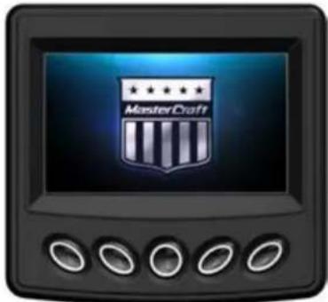
natural_image
Digital icon of a MasterCraft shield on a black monitor with five control buttons (no text or symbols beyond the shield)CARE AND MAINTENANCE
Only basic cleaning should be required to maintain the 7" video touch screen at its best. A soft cloth can be used for cleaning the units. Typical window cleaner or rubbing alcohol can also be used to clean the glass portion of the video screen display. Do not use harsh or abrasive cleaners on the unit.

CAUTION
Avoid contact between sharp or hard objects and the video touch screen because this can result in scratches or other permanent marks on the screen. Clean only with a soft cloth, using window cleaner or rubbing alcohol only. Never use harsh or abrasive cleaners on the unit, as this may result in damage to the unit that is not covered under warranty.
DISPLAY KEYS AND MENU BAR
Navigate by pressing the Display Keys. The Menu Bar changes according to the screen displayed. To navigate to a feature, press the Display Key under your desired feature or action.
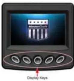
text_image
AmeriCout Display Keys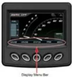
text_image
MATE OFF PULL DUAL DUAL EVE EVE EVE EVE Display Menu BarDisplay Keys Features And Actions
• Gauges
- Fuel
- MPH
- RPM
- Air Temperature
• Water Temperature (Optional)
• Water Depth (Optional)
Cruise Control
- ON or OFF
- Set Speed MPH
• Actual Speed MPH - NXT Wake Shaping Devices Position (Optional)
- Attitude Adjustment Plate Position (Optional)
Status
- Oil Pressure
- Engine Temperature
- Engine Hours
- Voltmeter
Trim Position (Optional)
- Position
- Attitude Adjustment Plate
- NXT Wake Shaping Devices
Actions
• (Arrow) Scrolls to other screens.
- (Down) Highlights the next setting down. Decreases set speed only on cruise screen.
- (Up) Highlights the next setting up. Increases set speed only on cruise screen.
• (Plus) Increases the setting value or is used to select.
- (Minus) Decreases the setting value or is used to select.
• (Select) Opens the highlighted feature.
ALARM ICONS
As an example, the Alarm Icons are active in the following illustration. You may change the value of the Fuel and Depth alarms from the User Settings screen. Some Alarms are set on the Factory Settings screen and require a Dealer Code to access.

text_image
RISKED OFF FREQ: 8.7 GRADE CREATED STATUS TRIM MEAL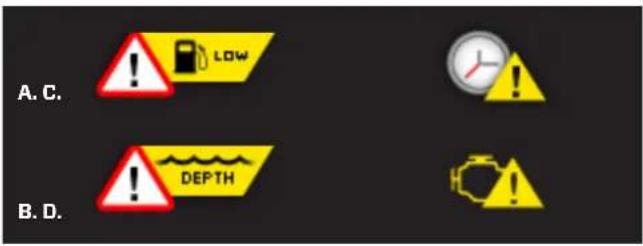
text_image
A. C. B. D. ! LOW ! DEPTHA = Low Fuel
The fuel in the tank is low and has reached the selected alarm level. Action: Refuel the vessel
B = Low Water Depth
The seawater level is shallow and has reached the selected alarm level. Shallow seawater may cause harm to vessel or vessel may bottom-out preventing safe passage.
Action: Move the vessel to deeper seawater.
C = Engine Service
Time for a scheduled engine maintenance or engine oil change. See Service Information for details.
Action: See your local dealer.
D = Engine Faults
An engine fault code is present. See Engine Diagnostics for details. Action: See your authorized MasterCraft dealer for assistance.
SCREEN FEATURES
Home
The Home screen can be accessed by pressing the Display Key under HOME in the Menu Bar or press the middle Display Key two times.
NOTE: The display in this document is set to US Standard Units. You may change it to Metric on the User Settings screen.
Home Screen Features:
- Fuel Tank Level
- MPH/KPH - Vessel Speed
- RPM - Engine Speed (Revolutions Per Minute)
- Cruise ON or OFF
• Water Depth (FT/M) (Optional)
To navigate to another screen, press the Display Key under an action in the Menu Bar.
NOTE: The Water Depth is an option that can be chosen on the Factory Settings Screen. If the option is selected as NO, it is not displayed. A Dealer Code is required to access the Factory Setting screen.
Gauge
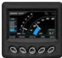
text_image
Digital display screen showing a speedometer interface with measurement scales and control buttonsFrom the Home screen, the Gauge screen can be accessed by pressing the Display Key under GAUGE in the Menu Bar.
Gauge Screen Features
- Fuel Tank Level
- MPH/KPH - Vessel Speed
- RPM – Engine Speed (Revolutions Per Minute)
• Air Temperature (°F/°C)
• Water Temperature (°F/°C) (Optional)
• Water Depth (FT/M) (Optional)
Press the HOME key to return to Home screen or press the ARROW key to scroll to other screens.
NOTE: The Water Depth and Water Temperature are options that can be chosen in the Factory Settings screen. If the option is selected as NO, it is not displayed. A Dealer Code is required to access the Factory Setting screen.
Status
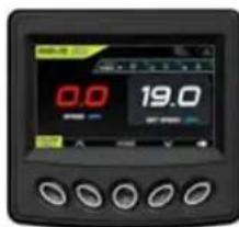
text_image
0.0 19.0From the Home screen, the Status screen can be accessed by pressing the Display Key under STATUS in the Menu Bar.
Status Screen Features
- Cruise ON or OFF
- Oil Pressure
- Engine Temperature
- Engine Hours
• Voltmeter
Press the HOME key to return to Home or press the ARROW key to scroll to other screens.
Trim
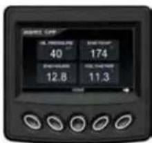
text_image
GPS NAV 40 174 12.8 11.3From the Home screen, the Trim screen can be accessed by pressing the Display Key under TRIM in the Menu Bar.
NOTE: The NXT Wake Shaping and Attitude Adjustment Plate options can be disabled in the Factory Settings screen which would also disable the Trim Screen. A Dealer Code is required to access the Factory Setting screen.
Trim Screen Features
• Port NXT Wake Shaping Position
• CTR Attitude Adjustment Plate Position
• STBD (Starboard) NXT Wake Shaping Position
- Cruise ON or OFF
Press the HOME key to return to Home or press the ARROW key to scroll to other screens.
NOTE: The Trim NXT Wake Shaping devices have multiple optional settings. As an example, if the Center Attitude Adjustment Plate and/or the NXT Wake Shaping devices are disabled in the Factory
Settings screen, the trim display positions will reflect that. A Dealer Code is required to access the Factory Setting Screen.
Main Menu
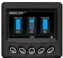
text_image
AMOUNT LET 95 25 95From the Home screen, the Main Menu screen can be accessed by pressing the Display Key under MENU in the Menu Bar.
Main Menu Screen Features
- User Settings
• Service Information - Engine Diagnostics
- Factory Settings
Press the Display Key under the UP and DOWN pointers to scroll the list and highlight a feature. Press the Display Key under SELECT to open a feature screen. Press the HOME key to return to the Home screen or press the ARROW key to scroll to other screens.
User Settings
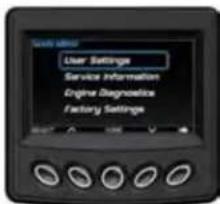
text_image
User Settings Service Information Engine Diagnostics Factory SettingsFrom the Main Menu screen, highlight the User Settings feature and press the Display Key under SELECT to open the User Setting screen.
The User Settings allow you to customize display features. To navigate to a feature, press the Display Key under your desired feature or action. Use the UP and DOWN pointers to scroll the list and highlight a feature. Use the PLUS and MINUS to change value or to select. Press the HOME key to go back; press it again to return to Home.
Units
US Standard (US Std) or Metric
Fuel Alarm
Sets the percent of fuel left in tank to deploy the alarm. Choices are 1% - 50%.
Min Depth Alarm
The choices are OFF or from 1 ft. to 98.5 ft.
Fire Extinguisher
The choices are Enable (pop-up notification) or Disable (pop-up notification).
Factory Reset
This choice restores all factory settings to their original values. Choices are: YES or NO.
Day Brightness
Sets the screen brightness for daylight. Settings are: 1%, 2%, 3%, 4%, 5% and 10-100% in increments of 10%.
Night Brightness
Sets the screen brightness for nighttime. Settings are: 1%, 2%, 3%, 4%, 5% and 10-100% in increments of 10%.
Gauge Brightness - Day
Sets the gauge brightness for daylight. Settings are: 10-100% in increments of 10%.
Gauge Brightness - Night.
Sets the gauge brightness for nighttime. Settings are: 10-100% in increments of 10%.
The display uses Night Brightness and Gauge Brightness Night when the Nav Light input is switched ON.
Service Information

text_image
SERVICE INFORMATION Software Version 68 Change Reset Disaster Service ResetFrom the Main Menu screen, highlight the Service Information feature and press the Display Key under SELECT to open the Service Information screen.
The Service Information screen displays the following features. To navigate to a feature, press the Display Key under your desired feature or action. Use the UP and DOWN pointers to scroll the list and highlight a feature and SELECT to open a feature screen.
Press the HOME key to go back; press it again to return to Home.
Software Version
This screen is an information only screen that provides the following:
• Application version and part number
- Operating system version and part number
- Boot loader version and part number;
- Software version.
Oil Change Reset
Select YES after an engine oil change to reset the internal clock for oil change alerts. An Oil Change alert is displayed the first time after 10 engine hours. Subsequent alerts are displayed at 50 engine hour intervals.
Dealer Service Reset
This provides the dealer with the ability to reset the clock. Service is required for the engine every 100 hours. When 100 engine hours has been reached, an alert is displayed to perform maintenance service on the engine.
NOTE: Access requires a dealer code. If reset is needed please contact your dealer.
Engine Diagnostics
text_image
Magnetic Transistor Power Supply 2.0 V Power Supply 2.0 V Power Supply 2.0 V Power Supply 2.0 V Power Supply 2.0 V Power Supply 2.0 V Power Supply 2.0 V Power Supply 2.0 V Power Supply 2.0 V Power Supply 2.0 V Power Supply 2.0 V Power Supply 2.0 V Power Supply 2.0 V Power SupplyFrom the Main Menu screen, highlight the Engine Diagnostics feature and press the Display Key under SELECT to open the Engine Diagnostics screen.
The Engine Diagnostics screen displays active and stored faults. When you open the Engine Diagnostics screen, the display will query the engine(s) ECU and provide feedback on any diagnostic codes that have been activated and stored in the ECU for service needs.
To navigate to a feature, press the Display Key under your desired feature or action. Use PREV and NEXT to scroll the fault list. Press ACTIVE FAULTS to toggle to STORED FAULTS. Press the MENU key to go back. Press the HOME key to return to Home.
Engine Diagnostics Screen Field Definitions
SPN (Suspect Parameter Number - Fault Code)
If not translated into text by the display, see the engine manufacturer's literature for the definition of the SPN number.
FMI (Failure Mode Indicator - Fault Code)
The FMI is defined by SAE J1939. If not translated into text, see the SAE standard or the engine manufacturer's literature.
Description Field
Most common SPNs and FMIs have text for the description stored in the display. If there is no text, then this SPN and FMI must be defined by referring to the engine manufacturer or the SAE J1939 standard.
Corrective Action
See dealer
Get Faults
Selecting GET FAULTS queries the Engine Control Unit (ECU) for feedback on diagnostic codes that have been activated and stored in the ECU for service needs.
Fault Code Pop-Ups
A fault condition will trigger a pop-up dialog box on the screen describing the nature of the fault.
Factory Settings
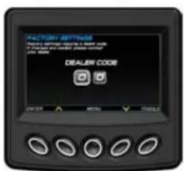
text_image
FACTORY SETTINGS FACTORY SETTINGS & ORDER NAME A PROCESSED ORDER, CHECK NAME FOR ORDER DEALER CODE ORDER BY: NO. 0123-0000 ORDER BY: NO. 0123-0000 ORDER BY: NO. 0123-0000 ORDER BY: NO. 0123-0000 ORDER BY: NO. 0123-0000 ORDER BY: NO. 0123-0000 ORDER BY: NO. 0123-0000 ORDER BY: NOTICE TOLERI
text_image
FACTORY SETTINGS Model KEY 20 Zone Off Cruise YES Center Tab YES Surf Table YES Depth / Water Temp. YESFrom the Main Menu screen, highlight the Factory Settings feature and press the Display Key under SELECT to open the Factory Setting screen.
The Factory Settings allow your dealer to customize features. A Dealer Code is required to access this screen.
TROUBLESHOOTING
Display Appears Not To Work Or Doesn't Come On.
- Display could be in sleep mode. Select a key on the keypad to activate the display.
- Check for loose connections at battery and display unit.
- Check for reversed polarity on the power connections.
- Verify battery has a minimum voltage of six volts.
Display resets or goes OFF when starting engine.
- Check display supply wires are connected properly to battery.
- Verify battery is charged properly.
- Check battery for efficient starter current.
Display has no back light.
Contact your MasterCraft service center.
Display has no keypad back light.
Contact your MasterCraft service center.

text_image
Masier CraftBOAT
OPERATIONS
$$ \frac{1}{2} = \frac{1}{2}\left( \frac{\ln x}{2} - \frac{\ln y}{2} \right) + \frac{1}{2}\left( \frac{\ln z}{2} - \frac{\ln y}{2} \right) $$
BASIC ELECTRICAL COMPONENTS
CIRCUIT BREAKERS
Models
All
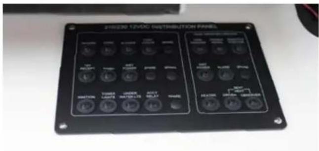
text_image
12VDCD 12VDC DISTRIBUTION PANEL OFF POWER INR POWER INR POWER INR POWER INR POWER INR POWER INR POWER INR POWER INR POWER INR POWER INR POWER INR POWER INR POWER INR POWER INR POWER INR POWER INR POWER INR POWER INR POWER INR POWER INR POWER INN POWER INN POWER INN POWER INN POWER INN POWER INN POWER INN POWER INN POWER INN POWER INN POWER INN POWER INN POWER INN POWER INN POWER INN POWER INN POWER INN POWER INN POWER INN POWER INN POWER INn POWER INn POWER INn POWER INn POWER INnPurpose
All major boat circuits are protected from shorting and overload by resettable circuit breakers. When an electrical fault is detected, mechanical switch circuit breakers will "trip" and automatically interrupt the flow of electricity. In a circuit breaker, when the electrical flow exceeds specified design tolerances, the electromagnetic bar snaps and cuts off further electrical passage. (The XStar features a complex, digital operation instead, with the same purpose.)
This can be extremely important in protecting persons on-board and also in preventing electrical fires.
In a water setting, such as those in which boats operate, it is especially important to avoid electrical shocks. As a result, MasterCraft utilizes GFI, or Ground Fault Interruption, circuit breaker boards, except in the XStar. These are solid-state devices that sense when there is a ground fault, which often occurs in instances involving water penetration.
Circuit breakers are preferred over fuses in boats for most operations because each fuse is usable only once. When the electrical flow is interrupted through a fuse, it then has to be replaced rather than reset. However, there are a few instances in which a fuse is preferable.
Access to these fuses is very limited and they should be replaced by an authorized MasterCraft dealer. Currently, the fuses are for amps at the battery switch panel, and in-line fuses for the fuel pump at the engine.
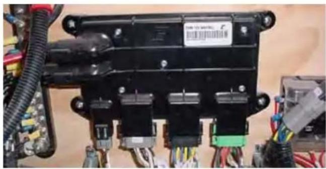
natural_image
Close-up of an electrical connector with visible wiring and connectors (no text or symbols)Location
The location of the main circuit breaker board is under the dash panel closeout, facing aft, except on the XStar, which does not have this panel, and the ProStar, where it is located on the starboard side of the walk-thru to the bow area. In some models, there is an additional breaker panel to assist with the accessory load, and where equipped, it is located near the battery box. There may also be a waterproof fuse for the stereo amplifier, where equipped. If the boat's accessories are malfunctioning, check and then reset breakers as necessary.
The XStar features digital switching. Instead of a breaker panel, there are four (4) PDM breakers and a main breaker that are located on the battery shut-off switch panel beneath the port aft seating.
The engine also has a fuse box that contains a variety of 10-30 amp fuses, located in the engine compartment on the engine.
If you suspect that any of these fuses may not be operating as designed, you should take your boat to your authorized MasterCraft service department for inspection and repair.
If during maintenance or inspection it becomes necessary to remove or reposition any of the engine's wiring or wire harness(es), verify that the wiring has been returned to its original position and that all harnesses are routed correctly before attempting to use the boat again. If a wiring clip or retainer breaks, replace it immediately.
Wiring is specifically routed to eliminate problems related to engine heat, and spray or immersion in liquids. Electrical problems may result if wiring is moved from its original position.
natural_image
Close-up of a black electronic component with orange wires on a red circuit board (no visible text or symbols)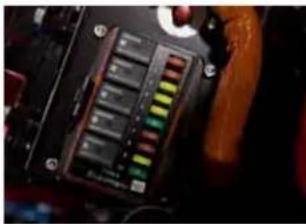
natural_image
Close-up of a black electronic device with a color-coded panel and indicator lights (no visible text or symbols)Operation
On all models except the XStar, if a problem develops with one of the circuits, switch OFF the circuit and wait for approximately one (1) minute. Then fully push the appropriate breaker button and switch ON the circuit. If the circuit continues to trip, there is a problem somewhere that must be attended to immediately. See your authorized MasterCraft service department to resolve this matter.
On the XStar, turn OFF the controlling switch; i.e., if the courtesy lights are not working, turn OFF the Courtesy Light switch. Allow a few seconds for the digital switching to reset, and then turn back ON. If the electrical function does not reset, see your authorized MasterCraft service department to resolve the issue.
Troubleshooting
Anytime a circuit breaker repeatedly trips, it is indicative of a situation that requires prompt attention. The boat should be presented to an authorized MasterCraft dealer for service prior to returning the boat to use.
SINGLE BATTERY
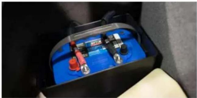
natural_image
Close-up of a blue battery pack with red and black components, placed inside a car seat (no visible text or symbols)Models
ProStar, NXT-Series
Purpose
When properly operated, the system will allow the boat engine to crank over with immediacy and support the various entertainment options on-board.
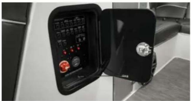
natural_image
Close-up of a black industrial control panel with open lid, showing digital displays and buttons (no readable text or symbols)Location
The battery functions from a battery switch.
NXT-Series: Switch is located under the port rear storage seat.
ProStar: Switch is located under the observer storage.
Operation
For normal operation the battery switch should be placed in the ON position. This allows the engine and all accessories to receive power. The engine will recharge the battery with the switch ON. For transportation of the boat by trailer and during storage, the battery switch should be placed in the OFF position to allow the battery to be isolated from all circuits.
CAUTION
NOTE: The switch knob may be removed when it is in the OFF position. This is a security feature to ensure that batteries are OFF. If the engine will not start because the battery is discharged, follow recharging instructions described in the Electrical Instructions section of the Owners Manual.
Bilge pumps will not operate in either the manual or automatic mode if the batteries are fully discharged. This condition may allow excessive water into the hull which can damage or sink the boat. Make frequent checks of battery charge and bilge pump function when boats are moored and exposed to the elements.
Troubleshooting
Because battery needs can vary substantially depending on a number of factors in usage from boating locations to number of electrical components on the boat, MasterCraft does not place a specific battery or batteries in the boat. The company strongly encourages you to discuss this critical matter with your authorized MasterCraft dealer prior to purchase and placement of the battery in the boat. All batteries must have 750 cca (cold cranking amps). Less can result in too-fast discharge of the battery charge and may leave boaters stranded on the water. Spiral cell batteries are recommended.
Review all electrical information provided in this Owner's Manual prior to first time operation of the boat.
DUAL BATTERIES
Models
All
Purpose
Because of the demanding drain on the electrical system by modern MasterCraft boats, it has become necessary to implement a dual battery system. When properly operated, the system will allow the boat engine to crank over with immediacy and support the various entertainment options on-board.
Location
Two batteries function from a dual battery switch, which are located under the port rear storage seat in most models. See the Guide to Individual Models section of this Owner's Manual. Battery and battery switch locations vary by model.
Operation
For normal operation the battery switch should be placed in the ON position. This allows the engine and all accessories to receive power. The engine will recharge both batteries with the switch ON. For transportation of the boat by trailer and during storage, the battery switch should be placed in the OFF position to allow both batteries to be isolated from all circuits.
NOTE: The switch knob may be removed when it is in the OFF position. This is a security feature to ensure that batteries are OFF. If the engine will not start because the battery is discharged, follow recharging instructions described in the Electrical Instructions section of the Owners Manual.
Troubleshooting
Because battery needs can vary substantially depending on a number of factors in usage from boating locations to number of electrical components on the boat, MasterCraft does not place a specific battery or batteries in the boat. The company strongly encourages you to discuss this critical matter with your authorized MasterCraft dealer prior to purchase and placement of the battery in the boat. All batteries must have 750 cca (cold cranking amps). Less can result in too-fast discharge of the battery charge and may leave boaters stranded of water. Spiral cell batteries are recommended.
Review all electrical information provided in this Owner's Manual prior to first time operation of the boat.
LOW VOLTAGE BATTERY ALARM
Models
All
Purpose
In the event that the stereo has been functioning when the boat is not ON and running, the voltage drain on the battery (or batteries) may result in difficulties with restarting the boat. It may also cause intermittent erroneous or fluctuating gauge readings. When the voltage level reaches 10.5 volts or below, the system will shut off the stereo and sound the alarm.
Location
Internal and unseen
Operation
Generally, the appropriate action is to leave the stereo OFF, as well as disengaging any other peripheral electrical components, and keying ON the engine. Running the engine at a moderate rate for several minutes without the additional drain of stereo and unnecessary electrical equipment will allow the alternator to recharge the battery or batteries, unless the battery(ies) have been used to the extent of their life span.

DANGER
Carbon monoxide is emitted from the engine's exhaust system. Never run the engine without proper ventilation. Do not run the engine in a confined space or where fumes may be trapped. Do not run the engine when the boat is stationary in calm wind conditions.
OTHER ALARMS
Models
All
Purpose
Sensors check the oil pressure, engine and transmission temperatures.
Location
Internal and unseen
Operation
If the system detects readings outside the acceptable range, the system shuts off the stereo and sounds the alarm for a period of one (1) minute. This signals the need to return to shore as soon as
possible and seek assistance from your authorized MasterCraft dealer's service department to diagnose and, if necessary, repair the problem.
BATTERY CHARGER
Models
All, as an option
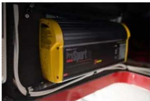
natural_image
Close-up of a black and yellow electronic device labeled 'Post-Sport' with visible wiring, placed inside a red container (no readable text beyond label)Purpose
As a convenience, a battery charger is offered as an option. The charger is designed to recharge the batteries and also to extend battery life in applications where the boat is stored.
These are three-stage electronic chargers, completely automatic, lightweight, and silent. Unlike most automotive chargers, this charger will not boil off the electrolytes in properly installed and maintained batteries.
Location
See the Guide to Individual Models section of this Owner's Manual. Battery locations vary by model.
Operation
The red and green LED lights, which are mounted on the charger face, indicate when the unit is recharging and maintaining the batteries. The battery charger will shut off when the batteries are fully charged.
Before charging a battery, do not operate the charger if the cables or an LED is damaged. Be sure that all accessories are OFF.
If the battery or batteries must be removed from the product, always remove the grounded terminal from the battery first. Be sure that the area around the battery is well ventilated while the battery is being charged. Also ensure that the battery terminals are free of corrosion. (See the Scheduled Maintenance section of this Owner's Manual for additional battery information.)
Troubleshooting
If the battery charger ever appears to be malfunctioning, see your authorized MasterCraft dealer for assistance. Repair or replacement of battery chargers should be done only through the dealer.

WARNING
When charging, batteries generate small amounts of dangerous hydrogen gas. This gas is highly explosive. Keep all sparks, flames and smoking well away from the area. Failure to follow instructions when charging a battery may cause an electrical charge or even an explosion of the battery, which could result in death or serious injury.
12-VOLT RECEPTACLE

natural_image
Close-up of a car's dashboard knob with a dial labeled '12V' (no additional text or symbols visible)Models
All. Some may have multiple receptacles.
Purpose
12-volt receptacles allow external electronic devices to charge from the boat's electrical system.
Location
MasterCraft boats have one (1) or more 12-volt receptacles. Examine your boat to determine whether there are additional outlets.
Operation
Prior to plugging any accessory into a 12-volt receptacle, ensure that the device is designed for use when connected to a 12-volt receptacle and will not be damaged by the connection to the receptacle. Never try to force a connection. Use of unacceptable chargers constitutes abuse of the system and MasterCraft will not be responsible for subsequent damage to the boat's electrical system or the charger or the device being charged. This is not covered under warranty.
Troubleshooting
If devices do not recharge after the expected period of time, verify that the correct type of charger has been used and that it was fully seated within the 12-volt receptacle. If it appears that the charger was the correct type and that it was fully seated but the device
still did not recharge, take the boat to your authorized MasterCraft dealer to determine whether the receptacle is malfunctioning and should be replaced. This is extremely rare.
IGNITION KEY SLOT
Ignition Key Slot
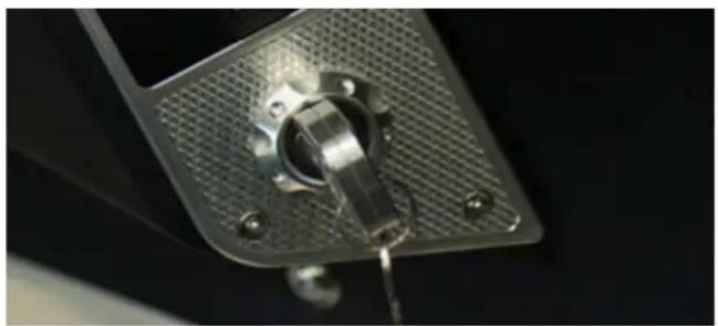
natural_image
Close-up of a metallic mechanical component with a textured surface and mounting holes (no visible text or symbols)Models
All
Purpose
The key is for safety and security. The key should be inserted prior to starting an outing, and removed at the conclusion. This is intended to prevent theft or unapproved use of the boat.
Boats are equipped with an ignition key, which must be inserted in the ignition key slot and used to activate the boat's electrical system. This, in turn, will allow the boat to be started and operated. The key will be in one of two (2) positions:
• OFF
• ON (electrical power is ON)
Location
The ignition key slot is located on the dash or driver's arm rest.
Operation
Insert the key into the key slot. Turn the key ON. Never start the engine without having first run the blower for at least four (4) minutes.
Never leave the ignition switch in the ON position without the engine running, as this will cause the battery to discharge.
Troubleshooting
If the key will not turn after being inserted in the key slot, it is likely to be the wrong key.
If the key turns but no electrical power occurs, check the voltmeter for a reading. If it is lower than 10.5 volts or does not register, the battery(ies) require recharging. Use only a MasterCraft battery charger.
DO NOT attempt to jump start the battery from a vehicle or another boat as this can cause an overload of the boat's electrical system, resulting in significant damage to the boat that is not covered under the warranty.
CAUTION
Attempting to jump start a battery or batteries on a MasterCraft boat, regardless of battery brand, from a vehicle or another boat can cause an overload to the boat's electrical system, resulting in significant damage to the electrical system. This is not covered under warranty.
IGNITION START-STOP
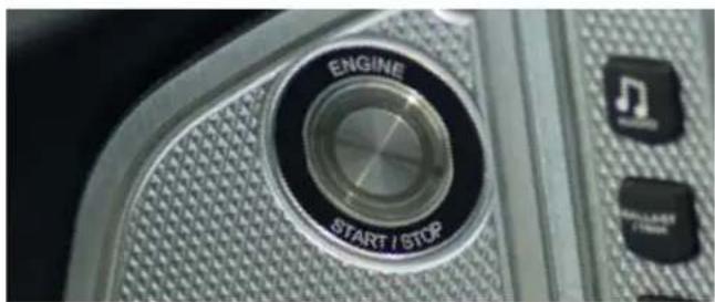
text_image
ENGINE START / STOPModels
All
Purpose
A START-STOP button is used to start the engine after the ignition key has been turned ON. The same START-STOP button turns the engine OFF.
Location
The START-STOP button is located on the dash or driver's armrest.
Operation
The process for starting the boat is:
- Insert the key and turn. (This turns ON the electrical system and prompts the battery(ies) to provide power.)
- Turn the blower ON and allow it to run for at least four (4) minutes before starting the engine.
- Momentarily press the engine START-STOP button.
- When it is time to turn the engine OFF, press and hold for three (3) seconds the START-STOP button. If the button is held for less than three (3) seconds, the engine will not turn OFF. This is a system design to avoid shutting off the engine if the button is inadvertently pressed or hit during operation.
Special Attention
This button affects only the engine. The electrical system will continue to operate as long as the key is turned ON.
If the key is left turned in the ON position after the outing, it will eventually run down the battery(ies) and the engine and all systems will not start as a result.
At the conclusion of the outing, turn the key to the OFF position and remove from the key slot. Doing so will ensure that you have shut down the electrical system, and it will prevent others from starting or running the boat.
Troubleshooting
if the key switch is in the ON position and the engine will not start by pressing the START-STOP BUTTON, check the voltmeter for a reading. If it is lower than 10.5 volts or does not register, the battery(ies) require recharging. Use only a MasterCraft battery charger. DO NOT attempt to jump start the battery from a vehicle or another boat because this can cause an overload of the
ENGINE EMERGENCY SAFETY STOP SWITCH
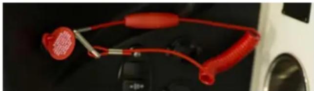
natural_image
Close-up of a red and silver automotive connector with a black handle, mounted on a white vehicle (no visible text or symbols)The safety switch lanyard must be attached to the operator whenever the engine is running. Attempting to override this system may result in death or serious injury!

DANGER
Purpose
The engine emergency safety stop switch, which is attached to a lanyard, is an ignition cut-off switch designed to stop the engine in the event the operator is thrown or moves away from the helm. The lanyard is equipped with a hook on one end that should be attached to your clothing or PFD, and the opposite end has a slide that fits over the ignition switch. Be sure that the slide is firmly attached to the ignition switch before starting the engine.
Location
The engine emergency safety stop connection is located near the throttle control box on the armrest. If the slide is left off or is loose, the engine will crank but will not start. Operators should NEVER attempt to override this safety system!
Troubleshooting
If the lanyard between the engine emergency safety stop becomes unattached from the connection point, the engine will shut down. Reattach the engine emergency safety stop and restart the engine.
OPERATIONAL CONTROL
Shift/Throttle Control
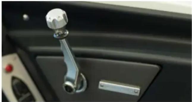
natural_image
Close-up of a metallic mechanical lever handle on a car intake door (no visible text or symbols)Models
All
Purpose
A one-hand, single-lever control operates as both gear shifter and throttle. The lever automatically locks in the neutral position (straight up and down) for safety.
Location
The shift/throttle control lever is located on the starboard side panel, adjacent to the driver's compartment (helm).
Operation
The lever can be moved from neutral only by raising the lifter under the ball knob. Shifting is accomplished by moving the lever forward or backward. Center (straight up) is neutral. Moving the lever forward engages the running gear; moving it back from center puts the drive train into reverse.
Never attempt to shift without the engine running! The neutral safety prevents the boat from starting the engine while in gear, but shifting while the engine is OFF will cause accelerated wear of the shifting gears.
SPECIAL NOTE: During regular warm-up of the engine, it is possible to temporarily increase the engine RPMs without moving the boat. To accomplish this, push in the button located at the bottom of the shift/throttle lever with one hand and pull up the "umbrella" (aluminum surround below the top of the knob). Move the lever to the desired position and then simultaneously release the button and umbrella. The engine will run with increased RPMs and can be increased or decreased by moving the lever. Returning the handle to the neutral position will bring the system back to neutral and reduce the engine RPMs to preset levels.
This function should be done sparingly. Over-rewing the engine for any extended period can cause undue wear and tear on the engine. Avoid advancing to wide-open-throttle and holding the RPMs at that level.
Troubleshooting
If the shift/throttle lever will not move, be certain that the lifter under the ball knob is lifted up before attempting to move the lever forward or aft. If the lever still will not move, contact your authorized MasterCraft dealer.
Never attempt to shove or force the lever. If it does not move smoothly when operated as indicated, there may be an issue involving the system that requires correction in an area under the deck, which is inaccessible to the consumer.
ADDITIONAL SAFETY SUPPORT
FIRE SUPPRESSION AND EXTINGUISHING
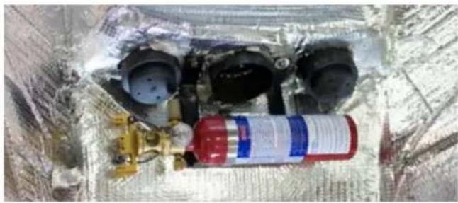
natural_image
Exterior view of a spacecraft with visible exhaust pipes and mechanical components (no text or symbols)See also the Safety section of this Owner's Manual.
Models
All

DANGER
Opening an engine compartment when there is indication of a fire inside can cause the fire to flare up and/or spread, which may result in serious injury or death to people onboard
Never attempt to fight a fire with your hands, feet, clothing or other material on-board the boat, other than approved fire suppression or fire extinguishing products as specified by MasterCraft. Failure to follow directions as outlined in this section can result in serious injury or death.
Purpose
MasterCraft has developed an extensive fire suppression and extinguishing system for its boats. All MasterCraft boats are equipped with an automatic fire suppression system. The automatic system operates from sensors in the engine room and will automatically release a clean-agent, gaseous chemical that does not leave residue behind. All boats have also been specified to carry a hand-held 2.5 lb. monoammonium phosphate expellant (dry chemical) unit, which is rated Class A (trash, wood and paper), Class B (UL Approved) and Class C (energized electrical equipment). These units should be used in situations other than engine compartment fires.
This is in addition to the suppression system in the engine compartment. Hand-held units should be replaced or recharged as soon as possible after use, or after 12 years from the date of manufacture. In the event of any evidence of a fire within the engine compartment, DO NOT OPEN THE ENGINE COMPARTMENT (BOX).
Opening an engine compartment when there is indication of a fire inside can cause the fire to flare up and/or spread, which may result in extensive damage or even sinking of the boat and/or serious injury or death to people on board.
Shut down the engine and blowers. Continuously discharge the
entire contents of the fire suppression unit immediately.
Location
Automatic Fire Extinguishers: All automatic fire extinguishers are located in the engine compartments on all boats. The locations of automatic fire suppression override units' manual override varies by model, but generally is in the vicinity of the helm.
Manual Fire Extinguishers: Manual fire extinguishers have various locations within the boat, but are generally located under either the observer seat or in the head and all are easily accessible. Be certain to determine the location of all fire suppression and extinguishing units on the boat. Your authorized MasterCraft dealer can assist you.
Operation
Automatic Fire Extinguisher Manual Override: It is possible to manually override the HFC-227 fire extinguishing system on all non-CE packaged boats. Pull the pin from the red handle labeled FIRE near the helm seat. Pull up on the FIRE handle to deploy the system.
Manual Fire Extinguishers: Pull the pin and squeeze the trigger.
Special Attention
In case of an engine compartment fire, shut down the engine and blowers before manual discharge, or immediately following the automatic discharge. Boats are equipped with a discharge indication light at the instrument panel or on the video display gauge at the helm.

DANGER
Following the activation of the automatic fire suppression system or a hand-held fire extinguisher, a careful determination should be made as to whether the boat can safely be operated. If there is any doubt or concern whatsoever, the boat should be towed to shore and/or dock for service by an authorized MasterCraft dealer prior to operating again. Failure to follow these instructions could result in death or serious injury/illness.
Troubleshooting
- If there is evidence of fire in the engine compartment of a V-drive boat and the automatic fire suppression system does not activate, pull the manual override (on domestic boats only). The override location is illustrated in the Guide to Individual Models of this Owner's Manual. Boat owners should also confirm this location with the assistance of an authorized MasterCraft dealer.
- If the manual override does not deploy, ensure all persons onboard are equipped with PFDs (personal flotation devices). If there is time, send visual and sound signals of the emergency. All persons should abandon ship and move to a safer location. Boats can be consumed by fire and even explode if there are fuel fumes.
- If a fire begins in another location other than the engine compartment, remove the fire extinguishers from their storage location,
- activate them as indicated above and attempt to put out the fire. Remain alert to the fact that a fire near or in the fuel tank or fuel lines is especially dangerous. Follow the instructions in the preceding paragraph, if a fuel fire begins or if the fire extinguisher(s) has not been effective in putting out the fire.
CLEATS
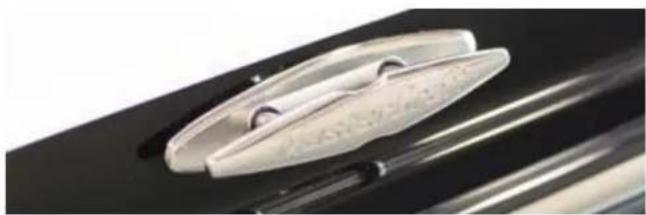
natural_image
Close-up of a metallic object with textured surface and reflective surface, possibly a lens or clip (no text or symbols visible)Models
All
Purpose
Cleats are an important feature of MasterCraft boats. The cleats allow boaters to tie-up to docks with ease and confidence.
Location
Cleat locations vary by model. (See Guide to Individual Models in this Owner's Manual to determine the locations for your model.)
Cleats will be on top deck sides of the bow, and aft near the transom. Some larger models also have mid-ship cleats. Some cleats are elevated slightly above the deck while others are pop-up cleats that fit flush with the deck when not in use.
Operation
Use marine-grade lines to loop over the cleat and tie up to the dock, allowing some slack in the rope. If there is any motion in the body of water, MasterCraft recommends also purchasing "fenders" from an aftermarket supplier to provide a cushion between the boat and the dock. Without a cushion, the boat's finished gel coat and graphics can be damaged. Such damage is not covered under warranty.

WARNING
The boat should be tied to docks with marine-grade lines ONLY to the cleats, and allowing some slack. Never tie-up the boat to the tower, mirror, seats or any other part of the boat. If the ability exists to tie up to all cleats on the side nearest to the dock, operators should do so. MasterCraft also recommends using fenders to cushion the side of the boat in the event of water motion. Otherwise, the boat gel coat and graphics may be damaged, and such damage is not covered under the warranty.
HORN
natural_image
Close-up of a white electronic device with a red button and 'DOWN' label (no readable text beyond branding)Models
All
Purpose
The horn allows the boat operator to alert other boaters by way of a well-known and loud sound.
Location
The horn is sounded by means of a button on the instrument panel or driver's armrest. It is a red button.
Operation
Pressing the button emits a loud and recognizable noise.
Troubleshooting
If the horn does not sound, check the main circuit breaker panel to see whether the circuit has tripped and needs to be reset. If the circuit does not require resetting, there may be an issue elsewhere in the system. Present the boat to an authorized MasterCraft dealer for repair.
MIRRORS

natural_image
Close-up of a metallic bicycle rear mirror mounted on a metal frame, with blurred green foliage background (no text or symbols visible)Models
All. In addition to the standard mirror, an optional mirror featuring different styling is also available. All mirrors function in the same fashion.
Purpose
The mirror allows the boat operator to see behind the boat. While this is very helpful, it is not a substitute for an observer. Whenever there is a wake boarder or skier behind the boat, the operator must also have an observer facing aft and alerting the operator when the tow has been lost. There are specific hand signals for activities, and this information is available via U.S. Coast Guard pamphlets and website.
Location
Mirrors are mounted on the windshield extrusion (metal frame) in the driver's compartment.
Operation
The mirror requires no operational procedure. It is adjustable, movable from port to starboard and back, up and down. Each operator should adjust the mirror to his or her maximum aft sighting while seated. (Boats are not to be operated with the driver in any location but fully seated in the driver's seat.)
Special Attention
MasterCraft recommends boat owners and operators use only MasterCraft installed mirrors. While there are a number of mirrors available through marine retailers, the mirror provided by MasterCraft was selected to maximize the range of vision for the driver of MasterCraft boats. If it becomes necessary to replace a mirror, use only MasterCraft mirrors.
Troubleshooting
If the mirror does not stay in place after it is adjusted to the driver's comfort, verify that the hardware holding the mirror in place is secure. If the driver's vision is obscured, be certain that the mirror is clean. Fingerprints, sun tan oil and a host of other common products found in boats can cause the mirror to become dirty and negatively affect the driver's vision when using the mirror. Clean mirrors properly, as described in the Care and Maintenance section of this Owner's Manual.
CAUTION
Prior to operation of the boat, verify that the mirror hardware is secure. Failure to do so may result in the mirror detaching from the windshield extrusion. The mirror could hit the operator or a passenger, resulting in injury.
SKI/WAKEBOARD/SURF ROPE
Models
May be purchased from an authorized MasterCraft dealer or aftermarket retailer.
Purpose
MasterCraft boats are equipped with watersports towing points as standard equipment, and may also offer other optional pylons and towers intended to be used to attach rope for skiing, wakeboarding and surfing. Note that tow ropes should never be attached to anything but the approved transom tow hook, pylon or tower. Care should also be taken by all on board to pay attention to the tow rope because it can snap back and hit people on-board when a skier or wakeboarder lets go of it. Usually, the rope simply skips along the water surface behind the boat, but it can become airborne, especially if it was taut prior to release.

WARNING
Ski/wakeboard rope should never be attached to anything but approved pylons and towers because it may otherwise break free or cause other items to break under load. People on board, as well as skiers and/or wake boarders could be injured. Also, operators and passengers should always pay attention to the tow rope when the
boat is underway because tow ropes can snap back into the boat, which could result in injury.
Location
Attachment locations vary by model. See Guide to Individual Models section in this Owner's Manual to determine pylon and tower attachments for each model. MasterCraft recommends stowing rope when not in use. Feet, arms and bodies can become entangled with rope left on the deck or seating; rope left loose behind the boat can become airborne and swing around to strike people on board.
Operation
Failure to properly and securely attach to the tower, pylon or other MasterCraft designated attachment locations for each model could result in the rope coming loose. As noted in the above warning, individuals could be injured if the rope is not secure.

natural_image
Two water boats on a lake, one with a 'MasterDra' branding and the other with a child watching from waves; no visible text or symbols on the main subjects.BELOW DECK
BILGE SYSTEM, CENTER DRAIN, TRANSOM DRAIN PLUGS, SEA STRAINERS AND SCUPPERS
natural_image
Close-up of a mechanical component with a transparent lid and three blades, no visible text or symbols.CAUTION
Bilge pumps will not operate in either the manual or automatic mode if the batteries are fully discharged. This condition may allow excessive water into the hull which can damage or sink the boat. Make frequent checks of battery charge and bilge pump function when boats are moored and exposed to the elements.
Models
All
Purpose
Water inevitably intrudes into any boat. MasterCraft boats are designed to expel the water via the bilge system. When on the water, bilge pumps will expel water. Bilge pump sensors allow the system to pump water overboard either automatically or manually. Because the bilge is located in the lowest portion of the boat's hull, it is not always readily apparent to individuals on-board whether there is water in the bilge or not. To allow operators the opportunity to manually verify water levels in the bilge, a center access plate or access door is built into every boat.
All boats (except Prostar) have two drain plugs, which allow water to be drained from the boat when the boat is OUT of the water. There is a center T-handle drain (the only one for a Prostar) and a transom drain plug. When out of the water, on a trailer or lift, water can normally be drained into the bilge system by opening the center drain.
Boats have sea strainers installed to assist in keeping debris out of the engine and water intake systems such as the ballast system.
X-55 models that are equipped with optional Salt Water Packages also have built-in systems, called scupper drains, to drain water off the open deck, sending the water through the hull and back into the body of water without going into the bilge.
Location
The bilge lines and pumps are beneath the decks. The center drain
location will vary slightly by model, but generally is found close to or adjacent to the driver's seat. It will be accessed through a hatch or access plate, which may be under marine carpet. A transom drain plug is on the centerline of the transom. Sea strainers are located in front of the engine. Scuppers, where equipped, are located on the lowest point of the deck, under the rear seats. Bilge pump-out locations are on the side of the boat. Depending on the model, the pump-out may be on the bow or the gunnel. See Guide to Individual Models in this Owner's Manual to determine the location of bilge pump-out. (They are often adjacent to ballast overflow/vents.) Pump-outs should never be obstructed.
The bilge system is controlled by a switch on the dash panel. The bilge pumps on all V-drive models will be in the automatic mode when the ignition key is turned ON. Some models may have two (2) switches, one for the forward bilge and one for the aft. In these instances, the switches will be marked. The manual and automatic bilge discharge system is never completely OFF. When in the automatic (default) position, a sensor alerts the system to discharge water from the bilge area.
Boat operators are advised to leave the switch in the automatic position, unless there appears to be excess water in the bilge as viewed through the center plate. In that event, the bilge pump can be manually activated by turning the bilge pump switch to the manual ON position. Return the switch to the automatic position when finished emptying the bilge. Leaving the switch in manual mode can result in damage to the pump and may not be covered by warranty!
CAUTION
Return the bilge switch to automatic any time it has been turned to manual to remove water from the bilge. Operators should monitor the water level through the center drain and ensure that the bilge pump(s) does not continue to operate after the bilge is emptied. Note that a small amount of water in the bilge is acceptable, except when winterizing the bilge system. Failure to follow instructions may result in damage to the bilge system, which may not be covered under warranty!
natural_image
Close-up of a metallic industrial component with a circular dial and bolted base (no visible text or symbols)Drain plugs should be loosened and removed when the boat is out
of the water to allow additional drainage of the bilge system. Always ensure that the transom drain plugs have been tightened in place prior to launching the boat into the water. Failure to do so can result in water intruding and overwhelming the system, sinking the boat.

WARNING
Transom plugs should be opened only when the boat is ashore. Removing the plugs allows additional drainage of the bilge system. The transom plugs must always be secured tightly in place prior to launching the boat into the water. Failure to do so will allow water to intrude into the bilge system and may result in serious injury or death as a result of the boat sinking.
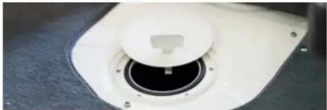
natural_image
Close-up of a white mechanical component with a circular opening and mounting holes (no visible text or symbols)Center drain piehole lids should be secured prior to boat operation. It can be possible to misdirect the cross-threads when reinstalling. Retry until the lid is secure, level with the deck. Not only can additional water from the deck intrude if the lid is not secured, but individuals on-board may injure themselves if they misstep in the area of the center drain.
The sea strainer should be checked before each outing. See the Care and Maintenance section of this Owner's Manual for details on how to properly inspect it. As equipped, the strainer operates automatically and does not require a switch or gauge to monitor. Regular maintenance, however, is important.
SPECIAL NOTE: Because the bilge pump operates even when the boat is shut OFF to prevent excessive water on board, if the pump runs fairly frequently, it can cause the battery(ies) to fully discharge. This is a signal that the boat is either taking on too much water from a leak or that the boat is being left in the water for periods that are too long. Anytime the battery is low or discharged, properly recharge it prior to operation.
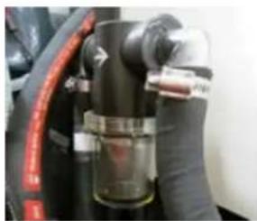
natural_image
Close-up of a mechanical device with black components and red wiring (no visible text or symbols)Bilge pumps will not operate in either the manual or automatic mode if the batteries are fully discharged. This condition may allow excessive water in the hull, which can damage or sink the boat. Make frequent checks of the battery charge and bilge pump function when the boats are moored and exposed to the elements.
Troubleshooting
The bilge system is among the most important systems in the boat. Attention should always be paid to proper operation.
- If the boat does not automatically pump water out of the system when the ignition key is ON, verify that the bilge switch is turned to automatic.
- If it is turned to automatic but still is not pumping when there is evidence of water in the bilge as viewed through the center drain, turn the switch to manual as needed to pump out the water. Be certain to follow the instructions above and do not leave the switch turned to manual after water is evacuated.
- If the bilge pump(s) still does not work when turned to manual, check the circuit breaker panel to ensure that electricity is moving between the switch and the pump. If the circuit breaker, which is marked, has tripped, reset it to ON.
- If the bilge pump(s) still does not work, it may be evidence of debris in the system or failure of the ballast pump impeller, which must be replaced on a regular basis as detailed in the Care and Maintenance section of this Owner's Manual. This is a serious concern. The bilge system keeps the boat from filling with excess water that may cause imbalance in the boat's trim. Under the worst possible conditions, the boat can sink. If the system fails
while on a body of water, return to shore IMMEDIATELY! Have all people on-board put on PFDs (personal flotation devices). Signal for emergency help. If persons on-board have working cell phones, contact help. After returning to shore, take the boat to an authorized MasterCraft dealer as soon as possible for repairs and do not use the boat again until it has been properly repaired.

DANGER
An inoperable bilge system can result in the boat taking on excessive amounts of water, resulting in significant damage to the boat, even sinking. Persons on board should wear PFDs and be prepared to abandon ship if the boat is on an outing. Operators should signal for emergency help and return to shore IMMEDIATELY and have the boat repaired. Failure to follow instructions can result in serious injury or death.
TRANSOM PROTECTION FILM
Model
All
Purpose
To provide a clear barrier between the transom of the boat and the numerous outside elements, such as watersports gear, that are present to cause damage to the finish of the hull.
Location
Exterior Transom Wall
BLOWER SYSTEM
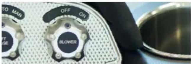
text_image
TO MAN OFF ON BLOWER LEFT LAGEModels
All
Purpose
The blower system is one of the most critical systems on the boat. A natural by-product of operating the engine is the creation of unseen fumes. Carbon monoxide is discussed in the Safety section of this Owner's Manual. The engine will also create flammable, ignitable gasoline and/or battery fumes. Dispensed into the open air, they are quickly diffused and pose little to no threat to well-being. However, if the fumes are not released by opening the engine compartment and operating the blower for a minimum of four (4) minutes before starting the engine (even if the engine has not been operated for some time), the accumulated fumes may explode when the engine is started.

DANGER
To prevent a possible explosion, operate the blower for at least four (4) minutes before starting the engine and always when at idle or slow running speed. Explosive gasoline and/or battery fumes may be present in the engine compartment. Failure to operate the blower as instructed may cause improper ventilation of the boat engine and bilge areas, and fuel vapors can accumulate in this area, causing a fire or explosion which may result in serious injury or death!
Location
The blower system is mostly unseen by those on-board. A two-position switch activates the engine box ventilation blower, and it is located on the dash panel. The engine compartment blower exhausts fumes through vents located on the transom of the boat
Operation
X-series/ProStar: Turn the switch to the right to turn the blower ON. Turn the switch to the left to turn the blower OFF.
NXT: Flip the toggle switch up to turn the blower ON. Flip the switch down to turn the blower OFF.
XStar: Push the toggle switch on the throttle panel up to turn the blower ON. Flip the switch down to turn the blower OFF. The blower will operate without the ignition key inserted and turned ON. The engine does not have to be started and running in order for the blower to work. Switches can be left on indefinitely to continuously allow removal of fumes.
NOTE: Blower operation drains energy from the battery.
SPECIAL NOTE: The blower must operate for a minimum of four (4) minutes before starting the engine at any time. The blower must also be operated during idle and slow-speed running, but is not necessary during cruising speed.
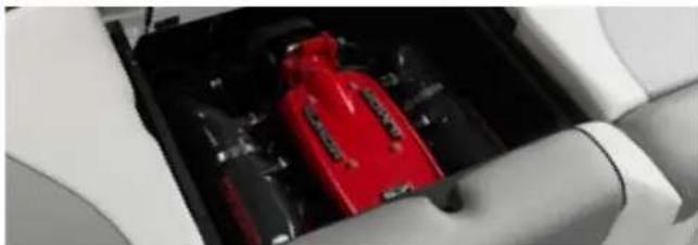
natural_image
Close-up of a car interior showing a red brake caliper and black plastic components (no visible text or symbols)Troubleshooting
NEVER OPERATE THE BOAT IF THE BLOWER SYSTEM IS INOPERABLE OR NOT WORKING PROPERLY. SEE THE DANGER WARNING ABOVE.
- The blower hums audibly when it is operating. If it is not functioning, turn the ignition key to ON and verify on the voltmeter that the electrical system is charging at least 11.5 volts or higher. If it is not, it will be necessary to recharge the battery(ies). See the
- Electrical information in this section of the Owner's Manual for proper procedure.
- If there is sufficient charge indicated, but the blower still is not operating properly, DO NOT LAUNCH THE BOAT. Take the boat to an authorized MasterCraft dealer for repair.
STEERING SYSTEM
Models
All
Purpose
The steering system controls the direction in which the boat moves.
Location
Except for the steering wheel and shift/throttle control at the helm, the steering system is not visible under normal circumstances. In a V-drive boat, the mechanism is located on the starboard side of the engine compartment.
To lubricate the control mechanism on the standard system as part of the annual maintenance (as described in the Care and Maintenance section of this Owner's Manual), locate the specific connection for your boat.
With the exception of the XStar, which is equipped with hydraulic steering, the steering wheel is mounted on a tilt mechanism that allows adjustment of the steering wheel angle to meet the needs and comfort of the operator. The system was designed to be used by operators who are sitting down in the driver's seat. Standing or manipulating the steering wheel in any other manner could cause loss of control.
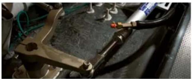
natural_image
Close-up of mechanical components including a tool and tubing, with no visible text or symbols.
WARNING
Boats underway must always be operated from a seated position at the helm. The driver's seat and the steering wheel are adjustable and should be placed at the location most comfortable and in control for each individual operator. Trying to drive a boat while standing or in any other way manipulating the steering system could result in loss of control of the boat. This may lead to serious injury or even death for those on-board.
See Shift/Throttle Control information elsewhere this section of the Owner's Manual.
Operation
The steering of a boat is very similar to that of a car or truck, but it will generally respond less quickly due to operation in the water, which is more dense than air. Read the Starting and Basic Operations information and Operational Hints that appear in the Preparation section of this Owner's Manual for more detail and assistance.
Troubleshooting
At any time, if the steering is sluggish, difficult, or shows any signs of not working smoothly and properly, the boat should immediately be taken to an authorized MasterDraft dealer for attention.
The hydraulic steering system is not accessible to the consumer for repair or maintenance, all of which should be done by an authorized MasterCraft dealer. Most of the standard steering system repairs are also accessible only by the dealer.
WATER JET BOW THRUSTER
Models
Installed on X46 and X26, as an option.
Purpose
A bow thruster allows for greater maneuverability, especially in tight quarters such as while docking the boat.
Location
The port and starboard jets are located near the bow, just under the waterline. The water pump is remote-mounted with the outlet plumbed to a "Y" valve that diverts the water to each jet. The thrusters are controlled by a joystick on the driver's armrest.
Operation
When the joystick is moved left or right, the bow of the boat moves port or starboard respectively. The joystick controls the "Y" valve, which (when fully opened) to one side or the other, energizes the electric water pump. The thrust developed by the pump is diverted by the "Y" valve to the opposite side, causing the bow to move away from the thrust.
Operate the thruster in pulses of a few seconds or more. However, do not operate for more than thirty (30) seconds continuously at one time. Allow some cooling time between periods of heavy usage.
If the pump overheats, a thermal protector will shut down the pump for approximately ten (10) minutes to allow the motor to cool. It then resets automatically.
Troubleshooting
- If the joystick is unresponsive, check that the bow thruster battery switch is ON. If it is on, check the circuit breaker box to be certain that it has not tripped.
- If the pump runs when moving the joystick, but no action results, check that the inlet and outlet valves are open.
- If the joystick, pump and valves are all operational but there is still no action, check to be certain there is no debris in the inlet screen.
- If the bow thruster still is not operating properly, take the boat to an authorized MasterCraft dealer because other potential solutions are in areas of the boat not accessible to the consumer.
ZINC ANODE
Models
All except ProStar, as part of the Salt Water Package option.
Purpose
If the boat is operated in salt, polluted or brackish waters, even temporarily, the boat should be equipped with a transom-mounted zinc anode to prevent damage to those metal parts coming in contact with the water.
The zinc is, by design, self-sacrificing. It is slowly eroded away by electrolytic action and requires periodic inspection for deterioration. When the zinc has eroded to approximately one-half (1/2) of its original size, it must be replaced to continue protection, or damage to other metal parts may result.
Location
The anode is mounted on the transom.
Operation
There is no operation required. Boat owners should periodically examine the anode to determine how much erosion has occurred and consult an authorized MasterCraft dealer to determine the appropriate time to replace it.
natural_image
Close-up of a hand holding a small metallic component with two circular holes, no visible text or symbols.VISUAL ASSISTANCE
NAVIGATION/ANCHOR LIGHTS

natural_image
Close-up of a green gemstone ring with a dark blue base, resting on a black surface (no text or symbols visible)
natural_image
Close-up of a car's head panel with a glossy red light and black base (no text or symbols visible)
DANGER
MasterCraft boats should not be operated at night or in limited visibility even with navigation lights illuminated. The lights have limited visual range. Other boat operators may not see or understand the movements of your boat. When necessary to operate at night REDUCE SPEED, use visual and sound signals to slowly return to shore. Night operations may result in collisions or striking fixed objects that could result in death or serious injury.
Models
All
Purpose
Although MasterCraft boats are designed to be operated during daylight, there are instances in which operators may find themselves on the water at dawn, dusk or even at night. Weather conditions during daylight may also result in the need to run or anchor with the lights on.
Location
Vary by model. See the Guide to Individual Models in this Owner's Manual to determine the location of these lights for your model. Lights may be on the bow, gunnels (port light will be red and starboard light will be green), and/or the stern.
Operation
A three-position switch serves to activate exterior lighting. Turning the switch to the right position will activate bow and/or gunnel lights, and the anchor/mast light. The middle position is OFF, and the left position is for anchor-only lighting.
SPECIAL NOTE: The navigation lights are not designed for operation in full darkness with the boat underway at higher speeds. To protect persons on-board and to prevent damage to the boat, do not operate the boat under these conditions.
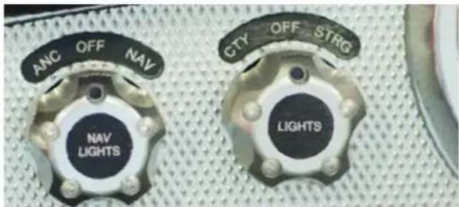
text_image
ANC OFF NAV NAV LIGHTS CTY OFF STRG LIGHTSMasterCraft boats should not be operated after dark, even with navigation lights on. The lights have limited range and luminosity. The boat may not be seen by other boat operations. In emergency situations or if an outing has not concluded prior to dark, use visual
and sound signals to slowly return to shore. Attempting to operate at higher speeds may result in damage to the boat as the operator may not be able to see obstructions in the water or other craft. This is not covered under warranty. Also, serious injury or death to individuals may result.
ADDITIONAL SPECIAL NOTE: In the ProStar model, if the boat is not equipped with tower lighting, the navigational lighting is valid for INLAND RULES ONLY.
Troubleshooting
If lights do not operate, check the main circuit breaker panel to determine if a circuit may have tripped. Reset the circuit; if it continues to trip, take the boat to an authorized MasterCraft dealer.
If the circuit breaker has not tripped, the bulb may have burned out. Although some lights are LED, which rarely burn out, it is possible. Take the boat to an authorized MasterCraft dealer to have the bulb replaced.
TOWER LIGHTS
Models
Models equipped with optional tower lights.
Purpose
Tower lights may be white or blue LED lights. These lights add visual appeal as well as providing additional light to the area aft of the boat. This can assist operators in keeping an eye on wakeboarders and skiers.
Location
The location of the aft light switch (where equipped) will vary by model and should be determined by the operator. Often the switch is on the driver's armrest. In some instances, there may be two (2) switches.
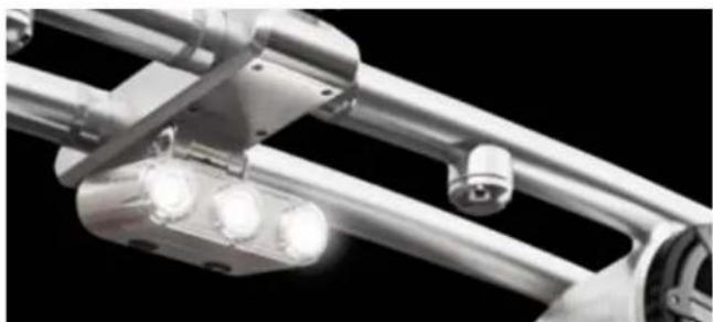
natural_image
Close-up of a metallic mechanical linkage with three glowing light bulbs against a black background (no text or symbols visible)Operation
In all instances, the lights operate by using two position switches, one position for ON and the other for OFF.
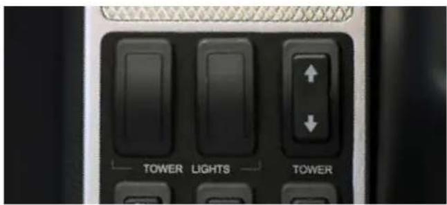
text_image
TOWER LIGHTS TOWERTroubleshooting
If lights do not operate, check the main circuit breaker panel to determine if a circuit may have tripped. Reset the circuit; if it continues to trip, take the boat to an authorized MasterCraft dealer. If the circuit breaker has not tripped, the bulb may have burned out. Although some lights are LED, which rarely burn out, it is possible. Take the boat to an authorized MasterCraft dealer to have the bulb replaced.
COURTESY/STORAGE COMPARTMENT LIGHTS
Models
All
Purpose
The courtesy lights and storage compartment lights provide illumination for the interior deck and compartments.
Location
Located on the transom below the waterline.
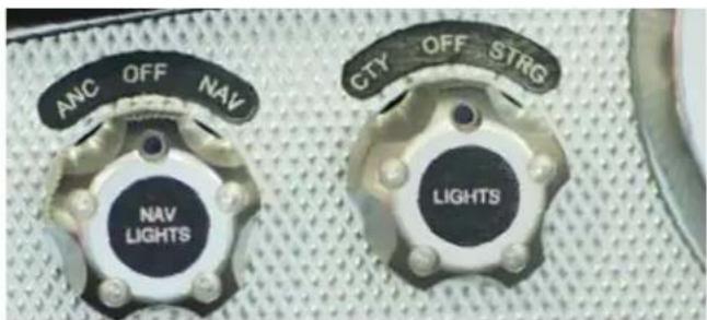
text_image
ANC OFF NAV NAV LIGHTS CTY OFF STRG LIGHTSOperation
The switch is a three-position switch located on the dash panel that activates the courtesy lights or storage compartment(s) within the boat. Turning the switch to the left will turn the courtesy lights ON, and turning it to the right will turn the lights ON in the storage.
Troubleshooting
If lights do not operate, check the main circuit breaker panel to determine if a circuit may have tripped. Reset the circuit; if it continues to trip, take the boat to an authorized MasterCraft dealer.
If the circuit breaker has not tripped, the bulb may have burned out. Although some lights are LED, which rarely burn out, it is possible. Take the boat to an authorized MasterCraft dealer to have the bulb replaced.
UNDERWATER LIGHTS
Models
All models, as an option.
Purpose
Underwater lights provide a significant improvement in visual illumination of the water beneath swim platforms and in the area surrounding the boat stern. In shallow water, this can be especially useful in determining safer operations.
Location
Blue lights, located on the transom below the waterline.
Operation
The combination switch is mounted in an aft position (transom or storage area) or controlled from the driver's armrest. The switch is marked. Press up on the switch to turn ON (a green LED light will be lighted when the lights are operating). Press down to turn OFF.

text_image
U/W LIGHT UNDER WATER LIGHTSAlso note that the underwater lights should never be operated unless the boat is in the water. Even though these are LED lights, they generate some heat and require the cooling effect of the water to avoid premature burn-out of the bulbs. Underwater lights may have thermal protection circuitry that will turn the light off when reaching high temperatures. Allow lights to cool in water in order to turn back on.
Troubleshooting
If lights do not operate, check the main circuit breaker panel to determine if a circuit may have tripped. Reset the circuit; if it continues to trip, take the boat to an authorized MasterCraft dealer. If the circuit breaker has not tripped, the bulb may have burned out. Although the lights are LED, which rarely burn out, it is possible. Take the boat to an authorized MasterCraft dealer to have the bulb replaced.
SPORT
ENHANCEMENT
ATTITUDE ADJUSTMENT PLATE
Models
Standard on the X20, X23, X26, X46 and XStar. All others Xseries and NXT models, as an option.
Purpose
When used properly, the plate improves the ride, reduces drag, increases speed and improves the fuel efficiency of the boat.
Location
The attitude adjustment plate is permanently attached to the boat's stern, below the waterline. Control is by way of either the video display (and explained more fully in the Video Display Gauges section of this Owner's Manual) or by manual switches located on the driver's armrest.
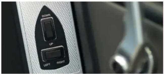
The operation of the attitude adjustment plates is basic. The plate is mounted with the actuator on the transom of the boat. When the plate is lowered, the water flow is redirected, creating an upward force at the boat's stern. When the stern rises, the bow will lower.
Since these actuators are electromechanical, they provide an immediate response at the touch of the switch. (The attitude adjustment plate can also be controlled through the Video Display Gauge.) Press and hold up to have the center tab come up. Pressing down on the switch will lower the plate/tabs.
(See GEN2 Wake Shaping Device information immediately following for boats equipped with both for information on how those tabs are operated.)
Because our models have different weights, lengths, speed and performance, it will take some practice for the operator to understand how the boat reacts with the attitude adjustment plate installed. The plate will allow your boat to get on plane faster and continue planing at lower speeds. This will improve visibility and the overall safety of your boat. When making adjustments with the attitude adjustment plate, use short momentary taps of the switch. Continued practice will help you become familiar with how the plates perform.
Special Attention
Because these plates can adversely affect boat handling if not utilized properly, the following information is provided to assist operators in determining the correct usage of the attitude adjustment plate(s).
Special Conditions
Head Sea: Lower the plate by tapping slightly on BOW DOWN on a single system. This will bring the bow down while maintaining speed. This also allows the hull of the boat to absorb the impact of the waves. This adjustment will result in a more efficient and smoother ride. Changes should be made in small increments to ensure maintaining control of the boat.
Following Sea: Make sure the plates are fully retracted by pressing BOW UP on both sides of a dual system, and BOW UP on a single system. This will bring the plate(s) up to a fully retracted position, d
decreasing lift in the stern and allowing the bow to rise. If the plate(s) is/are deployed, the bow may dig.
Shallow Water/Hole Shot: Lower the plate completely by pressing BOW DOWN. This provides lift in the stern of the boat and will keep the bow down. As you throttle up and speed increases, raise the tab by pressing LP.
Porpoising: To stop porpoising, press BOW DOWN on the attitude adjustment plate control. The plate(s) needs only to be deployed slightly to correct this adverse situation.

WARNING
Improper use of attitude adjustment may result in loss of control, which could result in serious injury or death.
- While at higher speeds, do not over-trim, as this will cause the bow to lower quickly, resulting in a reduction of speed and may cause the boat to veer.
- When in following seas or when running an inlet, the plates should be fully retracted. This will allow for optimal performance.
- Electromechanical actuators provide an instant response. When making adjustments, use short momentary taps of the switch.
Special Attention
On the X2, X10, X30, X48, and XSTAR models, attitude adjustment plates are limited to seventy-five percent (75%) maximum extension when the boat speed exceeds twenty miles per hour (20 mph) or thirty-two kilometers per hour (32 km/h).
On the X20 model, attitude adjustment plates are limited to seventy-five percent (75%) maximum extension when the boat speed exceeds twenty miles per hour (25 mph) or forty kilometers per hour (40 km/h).
On the X23 model, attitude adjustment plates are limited to eighty-five percent (85%) maximum extension when the boat speed exceeds twenty miles per hour (25 mph) or forty kilometers per hour (40 km/h). Maneuvering a boat with the attitude adjustment plate extended requires practice to master. Initial times running with the attitude adjustment plate extended should be done at low speed with plenty of room. This is critical to learning how the attitude adjustment plate affects control and maneuverability, especially when teaming the attitude adjustment plate with surf tabs.
Additional Special Attention
DO NOT use the attitude adjustment plate(s) to board the boat. The edges are sharp and can easily slice through skin. The plate(s) is also not sturdy enough to withstand many people's body weight. Damage to the plate(s) in this manner is not covered under warranty. Use only boarding ladders and swim platforms to board from the transom side when boats are equipped with an attitude adjustment plate(s).

CAUTION
Never use the attitude adjustment plate(s) to board or assist in boarding the boat. Sharp edges can cut individuals, causing potentially serious bleeding. Damage to the plate(s) from people using it to board the boat is not covered under warranty.
Additional Special Attention
Care should also be taken when backing up the boat in shallow water, removing boats from the water on steeply pitched access areas, or backing up with the boat on a trailer. The attitude adjustment plate(s) does not fold or retract, and it may require additional clearance to avoid damage to the plate(s). Resulting damage from failure to follow instructions is not covered under warranty.
CAUTION
Care must be taken to ensure that there is always sufficient clearance around the attitude adjustment plate, whether it is in the water or out, particularly on a trailer. The attitude adjustment plate(s) extends beyond the boat transom and is not foldable or retractable. Damage to the plate(s) from failure to allow sufficient clearance is not covered under warranty.
Troubleshooting
- If the switch(es) is/are unresponsive, check the main circuit break panel to determine if the circuit has tripped. Reset the circuit and try the switch again.
- If the circuit continues to trip, present the boat to an authorized MasterCraft dealer for repair.
- If the boat does not respond as noted in the above instructions, turn OFF the switch and do not use the attitude adjustment function until the system has been checked by authorized MasterCraft dealer because malfunction can result in loss of control of the boat.
GEN2 SURF SYSTEM
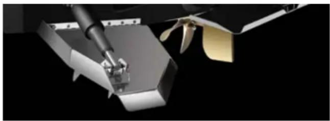
natural_image
Close-up of a robotic arm with propellers and a mechanical component against a black background (no text or symbols visible)Models
All X-Series and XStar, as an option.
Purpose
The GEN2 Wake Shaping Devices (WSDs) can be used in synch with presets or manually adjusted to help build and shape the surf wake to assist the rider in gaining a bigger push and a longer optimum ride for surfing. The center attitude adjustment plate (see instructions immediately above) can aid in this as well.
Location
The WSDs are installed on the port and starboard sides of the boat's stern. The switch is located on the armrest or it can be controlled through the Video Display Gauge.
Operation
In the presets, SURF RIGHT will deploy the port WSD, and SURF LEFT will deploy the starboard WSD. Surf tabs can also be used as trim tabs to help level the boat that has an unbalanced load on port or starboard or when a strong wind is present. Press the right trim button to make the boat rotate to the right (starboard) and press the left trim button to make the boat rotate left (port). To raise all devices, press and hold the UP button until the center attitude is at zero percent (0%). Release and press the UP button again to raise the GEN2 WSDs to zero percent (0%). This information will also appear in the Video Display Gauge, as equipped, and operates in the same manner.
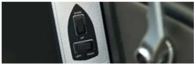
natural_image
Close-up of a device control panel with 'LEFT' and 'RIGHT' buttons, no visible text or symbols beyond labelsSpecial Attention
On the X2, X10, X30, X46, and XSTAR models, GEN2 WSDs are limited to seventy-five percent (75%) maximum extension when the boat speed exceeds twenty miles per hour (20 mph) or thirty-two kilometers per hour (32 km/h).
On the X20 and X23 models, GEN2 WSDs are limited to seventy-five percent (75%) maximum extension when the boat speed exceeds twenty five miles per hour (25 mph) or forty kilometers per hour (40 km/h). Maneuvering a boat with the WSDs extended requires practice to master. Initial times running with the surf tabs extended should be done at low speed with plenty of room. This is critical to learning how the WSDs affect control and maneuverability, especially when actuating WSDs with the attitude adjustment plate(s).

WARNING
Electromechanical actuators provide an instant response. When making adjustments, use short momentary taps of the switch.
BALLAST SYSTEMS
Models
A triple hard tank ballast system is standard on all X-series and NXT series boats. These ballast tanks cannot be removed after the boat has been built due to tight tolerance to fit between the deck and the Hull. The GEN2 Surf System, explained immediately previously to this section has additional plug-in bags. The bags connect through quick-connect fittings located in the rear storage compartment. The ProStar ballast system is similar to the X-Series, but features a single MTS. The NXT series has optional wake shaping devices and additional quick-connect bags when selected, but does not come with the GEN2 software.
Purpose
Ballast systems were specially designed for each model of MasterCraft boats to enhance enjoyment of boating. By creating deeper, more dynamic waves in the wake, boarding enthusiasts with skills ranging from beginners to professional boarders have discovered more enjoyable, even record-setting experiences. For simple outings and quicker reaction by the boat, ballast systems can be left empty. Filling ballast tanks, and optional bags, however, sets the stage for exciting and fun experiences.
Location
Ballast tanks are located between deck and hull, out-of-sight. Plugin, optional bags are located in the rear storage areas, on either side of the engine compartment. On the XStar, front ballast bags are located under the bow seating. Ballast fill and empty locations are underwater and should be kept clear of debris. (See Care and Maintenance section of this Owner's Manual for more detail) Ballast overflow locations are on the side of the boat. Depending on the model, the overflow may be on the bow or the gunnel. (See Guide to Individual Models in this Owner's Manual to determine the location of ballast overflow.) Fill, empty and overflow locations should never be obstructed. In addition to the manual switch on the driver's armrest, control may also be available through the Video Display Gauge. (See Video Display Gauge section of this Owner's Manual.)
Operation
The three-position switches are clearly marked: FILL, OFF (in center), and EMPTY. Toggle the switch in the direction desired. Be certain to return the switch to OFF when functions are complete. When the tank(s) is/are full, operators will see water being evacuated out the ballast overflow location(s). (See Guide to Individual Models in this Owner's Manual to determine the location of the ballast overflow.)
The ballast system in the XSeries, XStar and ProStar operates on an automated system that will shut down automatically when the emptying process has been completed.
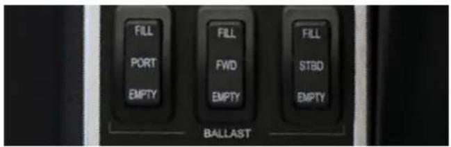
text_image
FILL PORT EMPTY FILL FWD EMPTY FILL STBD EMPTY BALLASTThe NXT system is not automatic. Tanks are full when the overflow begins to spit water out the side of the boat. To empty also requires manual operation. The system also empties water through the hullside. When tanks are empty, the water flow stops. It is critical to shut off the switch at this time.
CAUTION
Failure to return the manual operation switch on an NXT ballast system to OFF after emptying the tanks can cause the ballast pumps to fail. Such failure is not covered under warranty.
On models equipped with optional plug-in bags, if the bags are emptied and disconnected from the system, the original bridge connector MUST be reinstalled. Failure to do so will allow any water pumped into the rest of the ballast system to evacuate through the quick connect, which can result in flooding of the compartments and potentially sinking the boat.

WARNING
The original bridge connector in the ballast system must be reinstalled if the optional plug-in bags are removed from the system. Failure to do so will result in any water in the ballast system evacuating into the storage compartment, potentially flooding the compartments and could potentially sink the boat, resulting in serious injury or death.
In the systems that operate on timers, note that the timer operation varies by model. Timers may also be impacted by the addition of optional bags. See your authorized MasterCraft dealer for assistance in determining the proper setting for timers.
Special Attention
Be aware that the engine must be operated at 1500 RPM during the fill and empty processes. Check engine specifications for related engine idle speed, which, in some instances, may be too low for the empty/fill operation to be properly accomplished. Failure to increase engine RPM to the required level may result in malfunction or permanent damage to the ballast pumps that force the water through the system. Such damage is not covered under your warranty.
Special Attention
NEVER tow a trailer with water in the boat's ballast tank(s)!
Even small amounts of water can cause serious problems with the required balance of the boat on the trailer. (See the Trailer section of this Owner's Manual if you own a MasterCraft trailer. Note that this information is also applicable when towing with trailers built and sold by other manufacturers. Correct balance is critical to safe trailering.)

DANGER
Water MUST be pumped out of ballast tanks prior to towing the boat on any trailer. Even small amounts of water can adversely affect the balance of the boat on the trailer and tow connection, which can cause the tow vehicle driver to lose control of the rig. Failure to follow instructions can result in significant damage to the tow vehicle, trailer and/or boat, other vehicles on the road, and serious injury or death, including, but not limited to, bystanders.
Additional Special Attention
The ballast pump impeller MUST be replaced on a regular basis (at least annually, but more often may be necessary). Its purpose is to move water from the intake into the ballast tank, and vice versa when emptying the ballast tank. Through usage, the impeller, by design, will wear. (See Care and Maintenance section of this Owner's Manual.) Authorized MasterCraft dealers can provide guidance to locate any and all pumps. Failure to follow directions may result in damage to the ballast pump that is not covered under warranty.
CAUTION
Failure to follow instructions regarding the care and maintenance of ballast pumps as outlined in this Owner's Manual can result in damage to the ballast pump that is not covered under warranty.
Troubleshooting
- If the ballast pumps do not turn ON when the switch is activated or the touch screen is used, check that the circuit has not tripped on the main circuit breaker panel. Continual tripping after reset is indicative of an issue that requires the attention of an authorized MasterCraft dealer. - If the ballast pumps do not work when the circuit breaker has not been tripped, it is likely that the pump has malfunctioned, probably due to running while the tanks were empty. Regardless of cause, it is necessary to take the boat to an authorized MasterCraft dealer to determine whether the impeller and/or pump must be replaced.
Your authorized MasterCraft dealer has an extensive troubleshooting tree for ballast systems that includes parts of the system that are not accessible to the consumer. Because a malfunctioning ballast system can cause problems with control of the boat, no potential issue that arises with the system should ever be ignored.
PYLONS
Models
All
natural_image
Close-up of a mechanical component with a cylindrical shaft and flange, partially enclosed in a car seat (no visible text or symbols)
natural_image
Close-up of a dark, textured surface with a small object attached (no visible text or symbols)Purpose
When properly utilized, ski pylons allow skiers the opportunity to be towed behind the boat with a sensible and unobstructed view by individuals in observer seats.
Location
Varies by model, but pylons are generally adjacent to or integrated within aft seating. (See Guide to Individual Models in this Owner's Manual for specific model locations.)
Operation
See the Ski/Wakeboard Rope information under Additional Safety Support in this section of the Owner's Manual. Avoid tangling rope around the pylons or any other portion of the boat.
Special Attention
Some pylons are removable. In those instances, always be certain that the pylon has snapped securely into place prior to usage. Failure to do so could result in injury.

CAUTION
Ensure that removable ski pylons have securely snapped into place prior to use. Pylons that are not secure can become detached during operation. In these circumstances, the pylon could hit persons on board or skiers behind the boat, causing injury.
Troubleshooting
If the pylon will not lock into place, check for debris or other obstructions in the pylon housing. If the housing is clear and the pylon still will not snap securely, take the boat to an authorized MasterCraft dealer for service.
SWIM PLATFORMS
Models
All models. Materials vary, and most models also offer optional styles.
Purpose
Swim platforms provide easy access between the interior of the boat and the body of water. Care should always be taken by persons moving between the boat and the water. While the platforms have been designed to be slip-resistant, they may still become slick,
and footing can become difficult. All movement should be done with that in mind. Failure to exercise caution can lead to injury. Also, boisterous play is inappropriate on the swim platform because injury can occur.

CAUTION
Boisterous or rough-housing behavior on the swim platform, such as (but not limited to) trying to push others off the platform, can lead to injury.
Also, the boat MUST be turned OFF any time an individual is on the swim platform in the water near the stern of the boat. This is the location for exhaust fumes dispelled from the boat. See the Special Attention below and the Safety section of this Owner's Manual for additional information.
Location
Swim platforms are attached to the boat transom.
Operation
Platforms may be permanently attached to the transom. However, some platforms feature a bracket that allows the platform to fold down, reducing the amount of room required for storage. To determine whether the boat is so equipped, look beneath the platform and see if there is a bracket with a pin. If so, the swim
platform can be folded. To do so properly, follow these instructions:
NOTE: Platforms themselves are fairly heavy, and releasing the bracket may result in the platform falling down, and thereby striking the transom with excessive force. Please provide some kind of manual support to the platform at the time of releasing the bracket, and then slowly lower the platform into place for towing or storage.
NOTE: The attitude adjustment plate may also need to be lowered prior to lowering the swim platform.
Folding Down the Platform
Remove the safety hinge pins in each swim platform bracket. Begin by lifting the platform about four (4) inches upward while easing the platform away from the boat transom. This will allow the platform to move freely on the hinge.
NOTE: Ensure there is no tightness while the swim platform is being folded. There should be no binding during this action.
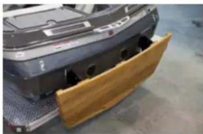
natural_image
Exterior view of a car chassis with wooden paneling on the side (no visible text or symbols)CAUTION
The platform must be raised and locked into position for transportation of the boat, as well as use of the platform while boating. Leaving the platform down may result in damage to the boat transom during transport that will not be covered by the warranty!
Securing the Platform
Lift the platform to an angle of approximately 20 degrees from the boat. Lightly push the platform (do not shove nor jam) toward the transom to allow the platform to set in place.
Verify that the platform is in the locked position and will not fall down. Failure to verify that the platform is locked may result in the platform falling while someone is on it and could result in injury.
Insert one (1) safety hinge pin into each platform bracket.
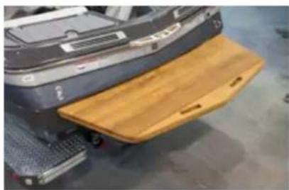
natural_image
Close-up of a robotic car with a wooden ramp and control panel, no visible text or symbols

WARNING
The platform must be raised and locked into position for use of the platform while boating. No one should be allowed on the platform until the platform is securely locked in place and the engine is OFF. Failure to do so may result in serious injury or death!
Special Attention
MasterCraft reminds consumers to review the Common Sense Approach section of this Owner's Manual, and pay particular attention to avoiding "teak surfing" or "platform dragging," which expose the participant to excess carbon monoxide; and to the information regarding use of the optional shower while standing or sitting on the swim platform with the engine OFF.

DANGER
Carbon monoxide is a colorless, tasteless, odorless and poisonous gas that accumulates rapidly and can cause serious injury or death. Exposure to carbon monoxide can be fatal in a matter of minutes. Exposure to even low concentrations of carbon monoxide must not be ignored because the effects of exposure to carbon monoxide can build up and be just as lethal as high concentrations. Carbon monoxide from exhaust pipes of inboard or outboard engines may build up inside and outside the boat in areas near exhaust vents, particularly during slow-speed operations. STAY
AWAY from these exhaust vent areas, which are located at the stern of the boat, and DO NOT swim or engage in any watersports or other activities in or near the stern area of the boat, including, without limitation, the swim platform and the rear sun deck, when the engine is in operation. Under no circumstances should the owner and/or operator allow persons to hold onto the swim platform while the engine is operating and the boat is in motion. These activities (sometimes known as "teak surfing" or "platform dragging," where the participant holds onto the swim platform and is pulled through the water, and/or "body surfs" immediately behind the boat) are extremely dangerous, highly likely to result in death or serious bodily injury, and are a misuse of this product.
Additional Special Attention
Swim platforms, especially those that feature Garapa Gold wood, require consistent maintenance to retain luster and finish. See the Care and Maintenance section of this Owner's Manual for important care requirements. Failure to follow instructions can result in damage to the platform that is not covered under warranty.
If shoes are worn when walking on the platform, they should be proper boating shoes. Black-soled shoes are likely to scuff the surface, resulting in marks that may be difficult to remove or even leave permanent marks that are not covered under warranty. Periodic cleaning with simple soap and water and a stiff brush will help keep your Garapa Gold platform looking new. Unprotected wood will turn gray and could split or separate. If this happens it may void the warranty.
New platforms have been sealed and finished with an oil-based, wood preservative by the manufacturer. Platforms will keep the new look and last for many, many years if properly maintained. For best results re-oil the platform and allow it to dry before the first use. If the boat spends a lot of long weekends on the lake with the swim platform in the water or if the platform sits uncovered in the sun, it should be oiled one or two times a month during the first season; then as needed after that. The platform should be covered when not in use or when stored for the winter.
Many products such as boiled linseed oil, tongue oil, wood oil and other outdoor wood preservatives can be found at marinas, paint stores or home improvement stores. Some oils such as linseed oil should be thinned with a thinner like mineral spirits before use. (70 percent oil-30 percent thinner.)
When oiling a platform, apply a coat of oil with a wet cloth, work into the seams, end grain and edges. Allow the oil to set approximately 15 minutes and then wipe off the excess oil with a dry cloth.
Do not let the oil dry on the platform in the sun. Excess oil should be removed with a dry cloth.
Troubleshooting
If at any time the swim platform does not feel secure (there should be no noticeable movement or "play" in relation to the rest of the boat), immediately leave the swim platform. Verify that, whether
permanently attached or held in place with brackets, the platform is fastened as designed. If it is not, stop using the swim platform and take the boat to an authorized MasterCraft dealer for repair.
SKI RACKS
Models
ProStar, as an option.
Purpose
The ski racks provide a sleek and attractive method to store skis in the gunwales on both sides of the boat interior. These ski racks are constructed with anodized aluminum and particular attention must be paid to prevent corrosion. See Corrosion in the Care and Maintenance section of this Owners Manual.
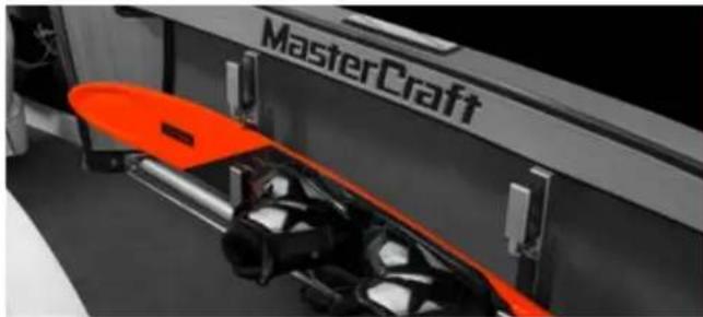
natural_image
Close-up of a red and orange electric vehicle fuel injector with visible components, no text or symbols present.Location
The ski racks are built into the gunwales on both sides of the boat interior.
Operation
The ski racks operate easily by tapping the lower bar of the assembly. Holding down on the bar keeps the ski rack holder open for easy access or storage of the skis. Releasing the lower bar closes the rack and holds the skis in place. Prior to operating the boat, always check that the skis are secure in the rack. Failure to do so could result in a ski or skis becoming dislodged during boat operation. This could result in the skis striking individuals seated in the aft portion of the boat or the skis going overboard.

Always verify that skis stowed in the gunwale ski racks are secure prior to operation of the boat. Otherwise, skis may become dislodged and strike passengers in the aft section of the boat or the skis going overboard.
TOWERS
Models
All. XSeries and XStars are equipped with the ZFT0 tower, the ZFT4 tower or the ZFTS tower, except when optionally deleted at the time the boat order is placed. The NXT and ProStar have their own unique towers.
Purpose
Towers add a whole new dimension of appealing boating enjoyment. Because of their versatility in adding wakeboarding, music and lighting to the experience, many boat owners consider towers to be an important addition to their boat.
Location
Towers are generally located amidships. On each model, a careful and thorough testing program was conducted by MasterCraft engineers to ensure maximum benefit as well as proper balance for the boat. This is extremely important and it is why MasterCraft strongly discourages the addition of aftermarket towers. Boat owners are strongly urged to purchase towers and tower accessories only through an authorized MasterCraft dealer. In fact, installation of any tower that is not specified and installed by MasterCraft may void our warranty.
Operation
Again, MasterCraft strongly encourages the occupants of the boat to review the Common Sense Approach and the Safety sections of this Owner's Manual prior to use of the boat and the tower component.
Raising and Lowering the NXT Tower
The NXT tower is an upright, fixed tower. It can be lowered by removing two hand knobs on either side of the tower.
Depending upon the total aggregate weight of the tower and any installed accessories, it is advisable to have a second person assist in steadying the tower during the raising and lowering process on the NXT tower.
Raising and Lowering the ProStar Tower
Lowering (And Leaving The Tower Attached):
- While applying some upward/forward pressure on the tower header, loosen one of the hand knobs.
- Repeat for the other side (or a second person can do this simultaneously). NOTE: Typically, it is easier to loosen both sides first compared to completely removing one knob and then loosening and removing the second. The angled threaded can put the tower/threads in a bind.
- Completely unscrew the hand knobs until they are disengaged (a spring pushes them out).
- Fold tower back and rest on motor box (or other padding to protect upholstery).
If Removing, Follow These Additional Steps:
• Pull excess wires out from under the deck.
- Disconnect the light wires.
NOTE: On the tower side, fold the wires up and push up in the tower tube. On the deck side, fold/loop the wires up and stuff back in the access hole.

natural_image
Interior view of a modern electric scooter with white cabin seats and metal frame (no visible text or symbols)CAUTION
Do not plug the wires together. This will act as a direct short if the light switch is turned on, resulting in a tripped circuit breaker or a blown fuse.
The male connector should be inserted in the groove in the plastic below the deck mount. Groove will be on the forward side of the hole.
- Looping the wires up so they create pressure against the deck/hole will provide additional resistance to them from falling down.
- DO NOT PUSH THE WIRES ALL THE WAY DOWN! Otherwise the side access panel will have to be removed to re-route them through the access hole.
- Ensuring the wires are clear, stand the tower all the back up to its normal operating position.
- From the back side of the tower, push the base of the tower leg forward.
- It should easily slide about 1/2" before catching on a small, raised feature intended to keep the tower from sliding out too easily and the operator losing control of it.
- A small push or bump with the palm of your hand should be enough to fully disengage the locking clip
- Be careful not to push/strike the tower hard enough that it falls on you. Very light pressure with your other hand on the upright should prevent this from happening. Too much pressure will possibly prevent the clip/foot from sliding and disengaging.
- Repeat on the other side.
- Remove tower from the boat.
If desired, the locking hook can be stowed in the tower mounting base.
- Push the hook forward in its groove, until it will fold sideways towards it stowed position.
- Collapse the locking clip in order to completely stow.
Installation is essentially the reversal of the removal, assuming the hook is stowed:
- Collapse locking clip and rotate out of the stowed position.
- Spring load will push the hook to the back of its groove. Note: Take care that you don't pinch your fingers!
- Place tower in front of the hooks in the upright position.
- Pull each tower foot back into the hook.
- Rotate tower back to hook up navigation light.
- Connect the light wires.
- Feed all of the excess wires and connectors below the deck through the access hole.
- The remaining wire should be straight.
- Slowly stand the tower back up, keeping an eye on the wires and ensuring they don't get pinched.
- Make sure that both tower feet/hooks are all the way to the back of the groove. If they are not, the hand knob threads won't be aligned.
- Get one hand knob started and threaded much of the way in. NOTE: If the threads don't start easily, it could be that the tower is in a slight bind. Back off the hand knob or lightly bump the tower/foot to free the bind before continuing to tighten.
- If you have two (2) people, starting and tightening together is easiest.
- Start the second hand knob and tighten until it is snug.
- On the other (original side), put a moderate amount of forward pressure on the tower header while torqueing the hand knob tight.
- Repeat the previous step on the second side. Note: These last two steps are important to ensure that the tower does not come loose during operation.
Lowering and Raising the ZFTO Tower

natural_image
Close-up of a modern car's roof and windshield (no visible text or symbols)The ZFTO tower is an upright, fixed tower. The towers can be lowered by removing two bolts, which are the front bolts on either side of the tower.
- Depending upon the total aggregate weight of the tower and any installed accessories, it is advisable to have a second person assist in steadying the tower during the raising and lowering process on the ZFTD tower.
Lowering and Raising the ZFT4 Tower

natural_image
Close-up of a robotic arm with articulated joints and a metallic component (no visible text or symbols)The ZFT4 tower can be manually raised or lowered (for storage or ease of towing over the road.) The locking mechanisms located on each side of the tower are pulled out to allow the tower to raise or lower.

WARNING
Always reinstall the locking mechanism on both sides of the ZFT4 tower immediately after raising or lowering the tower. Failure to do so could result in damage to the tower or collapse of the tower, which could result in serious injury or death.
Depending upon the total aggregate weight of the tower and any installed accessories, it is advisable to have a second person assist in steadying the tower during the raising and lowering process on the ZFT4 tower.
Lowering and Raising the ZFT5 Tower

natural_image
Black-and-white photo of a robotic arm assembling a mechanical component (no visible text or symbols)The ZFT5 tower operates under hydraulic power. The tower is controlled by a switch located below the shift/throttle control on the driver's armrest. The tower will stop raising or lowering at any point at which the operator releases the switch. However, the ZFT5 tower should NEVER tow individuals at any position other than full upright (where the tower will lock automatically).

CAUTION
When operating the ZFTS tower, individuals should take care to keep all body parts, especially fingers, away from hinge areas. The towers do not have sensors to stop movement if anything becomes pinched as the hinges move the tower up and down.

WARNING
Skiing, wakeboard or any type of towing behind all towers should occur only with the tower in the full, upright and locked position. Failure to do so could result in serious injury or death.
CAUTION
In over-the-road transit, the adjustable towers should be only full upright or fully lowered to avoid potential damage to the tower and/or boat. NXT / Prostar / ZFTO - Only in the up position.

DANGER
Always ensure that there are no people, power lines nor objects in the way when raising and lowering the tower. Individuals and their limbs may be subject to injury if caught in the path of the tower.
Special Attention
MasterCraft has carefully determined the maximum amount of accessories and total weight that the tower can safely hold. Ignoring this information could result in injury to the boat operator and/or passengers.

WARNING
85 pounds is the maximum aggregate weight allowed for accessories mounted on the tower. Exceeding this restriction can result in tower failure, which could cause serious injury or death to the boat operator and/or passengers.
Additional Special Attention
Occupants of the boat should never stand on, sit on or jump from the tower. Nothing but MasterCraft-approved sport towing should be attempted. (See the Safety section of this Owner's Manual.)
Troubleshooting
If a ZFT5 tower does not respond to the switch, verify that the circuit has not tripped at the pump, which is located on the port side aft corner of the seating, near the battery switch. The main circuit breaker board should also be checked. If the tower remains unresponsive, take the boat to an authorized MasterCraft dealer.
MasterCraft's towers are sturdy, well-designed equipment. With proper usage, operators should not experience other issues. However, if a tower ever appears to not be secure or if there is evidence of gel coat cracking or other stress to the deck at the tower legs, cease using the tower in any way and immediately present the boat to an authorized MasterCraft dealer for determination of necessary repairs. If it is determined that damage is the result of misuse of the product, such damage will not be covered under warranty.

WARNING
Immediately stop using the tower in any manner if it appears to be unsteady, unsecure or shows signs of gel coat cracking or other stress near the tower legs. Continuing to use the tower under these conditions could result in serious injury or even death. An authorized MasterCraft dealer must determine if there is repairable damage. If damage is the result of misuse of the product, such damage will not be covered under warranty.
TOWER ACCESSORY OPTIONS Models
All boats equipped with towers will have lights, speakers and board racks available as options.
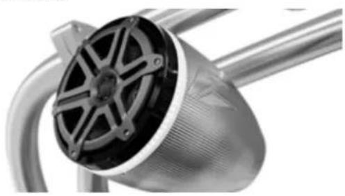
natural_image
Close-up of a metallic industrial pipe fitting with a circular component (no visible text or symbols)Purpose
Lights improve aft deck, swim platform and body of water visibility during low-light situations. Speakers provide enhanced enjoyment of entertainment. Board racks allow for a safe and secure fashion of carrying wakeboards and/or skis, and keeping them from underfoot on the deck.
Location
All of these options are found on the tower.
Operation
Lights: The lights will be either can lights or LED lights. Either work from a two-position, ON-OFF switch on the dash or driver's armrest, depending on model. Speaker ring lights and dimmer are an additional option, operated from a panel switch.
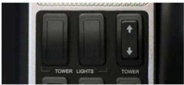
text_image
TOWER LIGHTS TOWERX-Series Speaker Lights: The speaker light switch panel is located on or around the armrest on the X-Series boats. The switch turns on the speaker lights in the cockpit and on the tower. The dimmer switch located next to it will dim the lights they will remain in the position that you left them in.
The XStar speaker light switch is located in the 4.3 touch under lights. The switch will turn on the cockpit lights and the tower speaker lights. In this boat you can't adjust the dimming because it is done in the digital switching.
Speakers: The speakers operate through the audio system. See the Video Display Gauge information for your model in this Owner's Manual for instructions on how the volume is controlled.
Board Racks: When board racks are ordered, there are three available options:
- Wakeboard storage on upper and lower arms
- Wakeboard upper, and wake surf lower
Note that, regardless of the type of board or ski, it should be securely clamped (or secured with a bungee cord on the ZFTO tower) so that board/ski does not come loose or disengage from the rack during boat operations. DO NOT attempt to place the wrong type of board within spokes (i.e., sialom skis in a board rack) because the fit will be improper. Resulting loss or damage to the board, or injury to individuals, is not the responsibility of the manufacturer.
Vertical Surf Racks: General Information
- Vertical Surf Racks on the ZFT4 towers are designed for Surf Boards, not intended to be used for wakeboards. The added weight and sharper edge of the wake boards can damage the foam and potentially the board.
- Due to the vertical orientation of the boards, the CG of the boards need to be centered in the fingers to keep the board from rotating
- when hitting waves. If you have issues with the boards rotating underway, this is likely the contributing factor. Pay attention to this when installing the boards, especially longer boards, to avoid issues while underway.
- In some cases, the fingers are nearly the widest point of the boat. They do not stick out beyond the shock, but caution is needed when pulling into a slip, especially in wavy conditions, as the rocking can make the fingers contact tall vertical dock supports before the rubrail does due the height of the fingers above the water. Over the tower mooring covers will require the safari racks to be removed.
Vertical Surf Racks: Installation/Removal
To install the safari surf racks, remove the detent pin from the mount, and carefully align the pocket in the cross bar with the groove in the mount. This can be done from inside the boat (bimini should be stowed for easier access) from the front side of the tower, however it is best done from a dock if possible.
The assembly will sink, so don't drop it in the water.
- Be careful when installing and removing the board racks from the mount. The rear finger can/will hit the tower tube and scuff/ scratch it.
- Once in the groove, the pin hole should easily align. If not, bump the fingers (normally in the forward direction) to make sure it is fully seated. If alignment is still off, check for debris or burrs on the components that would be preventing the alignment.
- Insert the locking push pin to secure the fingers in place.
- Once the locking pin is fully inserted, ensure it is locked by pulling outwards. If the pin is not secure, or there is not a pin to secure the racks, do not operate the boat with the racks installed.
- To remove the safari surf racks, remove the push pin by depressing the center button.
- Carefully lift up and rearward to get the crossbar out of the groove. Again, be careful not to hit the tower tube while doing so.
- Reinstall the push pin in the hole.
- Stow the fingers in a location that will not allow them to shift during transport. Stowing on upholstery is not recommended.
Surf Tow Points
- The side tow points are mounted on the inboard side of the ZFT4 tower. This is to minimize the interference of the rope and the boards/racks.
- The additional surf tows are intended for just that, surfing. It is highly discouraged to tow any other tow sports from these mounts, especially all 3 tower tow points at once.
- Since the tow points aren't vertical, a slack rope will have a better chance of falling off. It is recommended to double loop (if possible) rope around the tow point to reduce the risk of experiencing this issue.
Troubleshooting
Lights: If the lights do not work when the switch is turned ON, check the main circuit breaker panel to determine whether the circuit has tripped, and reset if it has. If the circuit continues to trip or if the circuit is on but the lights still do not work, take the boat to an authorized MasterCraft dealer for attention.
Speakers: If the audio speakers on the tower do not work, verify electrical circuits by checking the main circuit breaker panel. Reset if it has tripped. If it still does not work, take the boat to an authorized MasterCraft dealer for repair.
Board Racks: If boards will not sit securely in place, and it is determined that the proper board for the proper rack is in use, do not leave the board in the rack. Take the boat to an authorized Master-Craft dealer to determine the underlying cause.
COMFORT AND CONVENIENCE
STEREO COMPONENTS
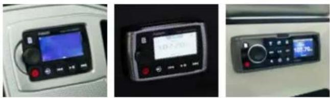
Models
Optional on NXT-Series. Standard on all other models.
Purpose
The stereo system provides enhanced enjoyment of the boating experience. The system includes a stereo AM/FM radio, remote controls, iPod and MP3 player connections, and may include a subwoofer and amps, as well as a Bluetooth connection.
Location
The stereo system operates either through the head unit display and controls, typically located on the passenger side of the boat; or a remote control. The remote control is a touch screen on the right side of the dash on the XStar and on the lower left side of the dash on XSeries boats. NXT-Series boats have the head units located on the left hand side of the dash.
Optional remote controls are available on the bow or transform for all models.
Optional remote controls are available on the bow for all XSeries models and the XStart
The iPod/USB plug-in is located on the glove box for all radios; the MP3 player jacks are below the throttle control on the driver's side of the helm. Subwoofer and amp locations vary by model. (See the Guide to Individual Models of this Owner's Manual to determine location for your individual model.)
Special Attention
Changing the factory settings on any stereo-related equipment may void the manufacturer's warranty.
Operation
The stereo and components come with a separate manual explaining operation of the devices. Please review and become familiar with the equipment.
The iPod interface option allows the unit to simply be plugged in and run off the boat's electrical system. An optional plug-in location for MP3 players is available.
Be aware that all such devices are a drain on the boat's battery and electrical system. Care should be taken to avoid excessive usage of such devices and by responding to any alarms that sound so that the boat's battery(ies) do not become fully discharged.
GLOVE BOX
natural_image
Close-up of a black electronic device casing with 'NEXT' branding and circular ports (no readable text beyond logo)Models
All
Purpose
The glove box provides easily accessible storage space for small items. MasterCraft recommends that you keep this Owner's Manual in a water-resistant plastic bag inside the glove box so that it is quick to find in the event that troubleshooting for any part of the boat is required.
Location
The glove box is located on the port side of the dash, forward of the observer seat.
Operation
Several different styles of glove box are featured, depending upon the model. All have a closable lid. To open the glove box lids that feature a recessed button, simply push in on the button and it will pop up and twist to disengage the lid from the box.
Over stuffing a glove box can interfere with the lid latch's ability to close properly.
Special Attention
Glove box lids should always be closed and latched any time the boat is in operation. While the boxes are water resistant, if the lid is not latched securely water can intrude and cause damage to anything inside the glove box. MasterCraft is not responsible for such damage. Any items placed in the glove box that cannot or should not become wet should be placed in water tight containers before placing them inside the glove box.
Troubleshooting
Any time the lid will not close and latch properly, see an authorized MasterCraft dealer. If it is not properly closed, damage could occur to the lid.
HEATER
natural_image
Close-up of a metallic mechanical component with concentric grooves (no visible text or symbols)
text_image
LO OFF HI HEATERModels
All models, as an option.
Purpose
Warmed air from an electrically powered heater box will be blown from vents within the boat deck, to keep occupants warms.
Location
Heater vents locations vary by model, but all are located within the cockpit. They typically reside in the driver's floor, either side of the cockpit in the cupholder inserts, and/or on the observer dash near the glove box. A heater tube and vent is typically installed near the floor.
Operation
The heater's three-position switch rotary control is turned left for ON (LOW), or turned right for ON (HIGH). The center position is OFF.
Excessive use will drain the battery(ies). See the battery information provided at the beginning of this section of this Owner's Manual to avoid potentially becoming stranded by a fully discharged battery or batteries. Pay attention to the voltmeter, any time the reading falls below 10.5 volts, the battery(ies) will require recharging, which must be done properly. That information is also contained in the beginning of this section.
Special Attention
In regular use, the heater should not require any routine maintenance. However, it is advisable to avoid placing items in front of the vents, particularly when the heater is in use. The heated air coming out could cause damage.
Never run the heater in a confined space, such as a garage or shop. Running the heater requires also running the engine and fumes from the engine can have deadly consequences. See also the Common Sense Approach in the Safety section of this Owner's Manual regarding carbon monoxide danger.
Carbon monoxide is emitted from the engine's exhaust system. Never run the engine without proper ventilation. Do not run the engine in a confined space or where fumes may be trapped.
Troubleshooting
If the heater fails to respond when the switch is turned to either of its ON positions, check on the main circuit breaker panel to ensure that the circuit has not tripped. If resetting does not correct the
problem or if it continues to trip, take the boat to an authorized MasterCraft dealer for repair. Also, while the air coming out of the vents may be cool at first, if it does not warm up within a reasonable period of time, take the boat to an authorized MasterCraft dealer.
SHOWER
Models
Many models offer a shower or wash down option.
Purpose
Showers, accessible through a shower wand, allow persons to rinse off with cool fresh water (the water is not heated) after returning to the boat from the body of water.
Location
Shower wands will be aft, inside a storage compartment or behind seating, depending on the model. It may also be inside the wet bar, on models so equipped with that option. See the Guide to individual Models section of this Owner's Manual to determine the basic location in your model. Switches to operate the shower are located on the transom. Access to fill the freshwater tank for the wash down option or the shower is located in various locations (generally the aft of the gunnel or on the transom). See the Guide to Individual Models section of this Owner's Manual to determine the location for your model.
Operation
A combination switch is mounted in an aft position (transom or storage area) and controls the optional shower function. The switch is marked. The two-position switch is pressed up for ON and down for OFF. The switches are marked for each and may also include the underwater lights, where equipped. The switches are operated as ON-OFF and should always be left in the OFF position when the system(s) is not in use. The instructions work whether the boat is equipped with one (1) or both of the options, but will not be found in boats that are not equipped with either option. Do not use the shower with the engine running. The shower wand location and limited length of the hose means that most individuals shower while at the transom or on the swim platform. Because this is also the location for the engine exhaust emissions, dangerous fumes may be present if the engine is allowed to run.

DANGER
Carbon monoxide is emitted from the engine's exhaust system. Do not use the shower or occupy the swim platform with the engine running. Never run the engine without proper ventilation. Do not run the engine in a confined space or where fumes may be trapped.
Routine maintenance is not required beyond occasionally checking the lines and head to be certain these elements are not damaged in any fashion, and that the hose continues to be in good condition. Be certain to follow the Storage & Winterization section's instructions found elsewhere in this Owner's Manual.
Troubleshooting
If the shower and/or wash down do not work when the switch is turned ON, verify at the main circuit breaker panel that the circuit has not tripped. Repeated tripping or if the system does not work when the circuit is on indicates a problem that requires the attention of an authorized MasterCraft dealer. The pump is not located in a consumer-accessible location. Also verify that the wand has no obstructions at the head that would prevent proper operation and that the line is not kinked, thereby inhibiting the flow of water.
SEAT HEATERS
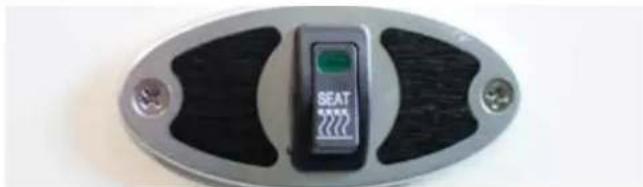
natural_image
Close-up of a metallic oval-shaped electronic device with a green control panel and black buttons (no visible text or symbols)Models
Optional on all models for driver's seat; certain models for observer's seat.
Purpose
The seat heat option allows the equipped seats to be warmed to temperatures above those of the ambient air.
Location
The electrical seat-heat mechanisms are located inside equipped seats. The seat heat switch is on the driver's armrest. In some models, an optional observer seat heat switch is available and will be found on the deck below the observer seat cushion.
Operation
A two-position switch allows heat to be turned ON for the driver's seat. Note that this switch and the observer's seat heat switch will operate only when the ignition is in the ON position.
Special Attention
Do not leave open food, sun tan oil, or other materials on the seats if the seat heat function is ON. Although the heat does not exceed a temperature at which skin can touch without burning, nonetheless the additional heat could cause some types of food or other materials to melt, causing a stain or damage that is not covered under warranty.
CAUTION
Do not leave unattended, open food or other materials that could melt, on a seat equipped with a seat heater that is or will be turned ON. The additional heat could cause melting, resulting in a stain or other damage that is not covered under warranty.
Troubleshooting
If the seat heat system does not work when the switch is ON, check at the main circuit breaker panel to ensure the circuit has not tripped. If so, reset. If the seat heater(s) still does not work or if the circuit continues to trip, take the boat to an authorized MasterCraft dealer.
ANCHOR

natural_image
Person standing near a white vehicle with chains, possibly a bus or container, in a natural setting (no visible text or symbols)Models
All, as an option
Purpose
The anchor allows the boat to be temporarily moored in relatively shallow water. Note that standard equipment does not include the line for the anchor. This is because needs will vary considerably by location of the body of water. The general rule of thumb is that the boat owner should purchase anchor line from a marine aftermarket company at a length about three-to-four (3-4) times the depth of the body of water in which the boat will be moored.
Location
Some models are equipped with anchors, and there will be a designated storage area or stowage location on the boat, normally in the forward area of the bow. Check with your dealer if you are uncertain about this area because it is important to keep the anchor stowed
when it is not in use. In some instances, ladders may also be stowed in this location.
Operation
MasterCraft anchors are manually operated. The anchor has a storage compartment at the front of the bow. After purchasing and securely attaching a line manufactured to be used in a marine environment as an anchor line, open the anchor storage compartment and remove the anchor. Toss over the side, ensuring that the anchor does not make contact with the boat deck or hull, as such contact could cause damage to the gel coat, which is not covered under warranty. Also use care in retracting the line and anchor to avoid damaging the deck and/or hull.
Always tie off to the bow. Never tie off solely to any position aft, including the transom.

CAUTION
The anchor has been provided to assist boaters in remaining in a chosen location. Boats should always be tied off to the bow and never solely to the aft. Note that use of the anchor system will not guarantee a properly anchored boat or that the boat will remain in a stationary position. Environmental, bottom conditions, current and tidal conditions must be taken into consideration when anchoring the boat. Only properly trained operators should set the
anchor for this system. Establishing a secure anchorage requires practice. Damage to your boat may result due to improper anchoring techniques.
Swimmers or anyone in the water in the area of the bow should remain aware of the anchor line anytime it is deployed. Even if it appears taut, an individual could become entangled in the line underwater, which could result in injury or death. It is also possible that people could cause the anchor to lose anchorage, causing the boat to move. If there is a current, the boat could become inaccessible to people in the water.

WARNING
Whenever the anchor line is deployed, individuals in the water nearby should avoid the line. Disrupting the line could cause the boat to move away from the chosen anchorage location. It is also possible that individuals could become entangled in the anchor line. If underwater, this could result in serious injury or even death.
Special Attention
MasterCraft suggests that operators monitor and verify the rewinding process to ensure that the line retracted in a smooth and even fashion. Anchors should never be pulled aboard and left on-deck because this can lead to potentially dangerous situations.

WARNING
Improperly stored anchors and/or anchor lines that have been improperly rewound may create a hazardous situation. People onboard can trip on improperly stored materials, which can result in injury. Improperly stored materials can also move too freely during boat operation and make contact with individuals, again causing injury. Properly store all anchors and lines whether the boat is in operation or not, any time the anchor and line are not in use. Never operate the boat with the anchor line deployed.
Troubleshooting
If the anchor line has been improperly rewound, have an authorized MasterCraft dealer assist in deploying and rewinding the line to its appropriate berth.
CANVAS COVERS
natural_image
Close-up of a black aircraft fuselage with visible structural components and no text or symbolsModels
All models, as an option.
Purpose
Depending on the canvas selected, it may provide protection from the sun for people on board and/or from the sun's rays, water or while towing, for areas of the boat. Canvas can also provide UV protection while boats are moored or stored.
Location
Covers can be installed over all the boat or only over sections of the boat. Check with an authorized MasterCraft dealer for details. This is something that can be added to the boat during ownership.
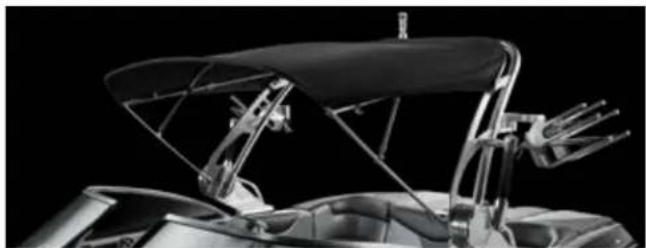
natural_image
Close-up of a car's front wheel assembly with black canopy and metal frame (no visible text or symbols)Operation
Most covers are intended for use when the boat is moored or stored. These canvas covers will snap or ratchet into place. However, the Bimini top offers shade while the boat is in use. The Bimini is installed over the helm and/or midsection of the boat. The Bimini legs will fold to allow for minimal wind resistance during towing or when riding across the body of water at higher speeds, or for storage. When folding the legs be certain to be careful to avoid pinching fingers when raising or lowering the legs. For balance, it is suggested that operators have an additional person assist when raising or lowering a Bimini top.
Special Attention
MasterCraft strongly recommends having an authorized MasterCraft dealer perform the installation of snap-on canvas such as cockpit and tonneau covers, because snap installation can cause "crazing" (unwanted spiderweb-like lines in the gel coat) if the installation is not done correctly. Such damage is not covered under warranty.
Additional Special Attention
On-going care of the canvas is required to keep the material in good condition for the life of the boat. See Cleaning the Boat section of this Owner's Manual for more information.
Additional Special Attention
Note that towing with unapproved covers on the boat may result in damage to the gel coat. MasterCraft recommends the use of our towable cover only for towing. Other canvas covers have been developed and are available only through authorized MasterCraft dealers for a variety of uses.
Additional Special Attention

CAUTION
The use of canvas covers, especially darkly colored ones, in hot, sunny conditions, can result in temperatures inside the boat in excess of 140^ F/ 60^ C. Prolonged high temperatures can heat interior metal and other surfaces to the point that brief contact with the skin may cause serious burns. Carefully remove the cover and allow the interior to ventilate and cool before allowing anyone on board.
TRANSOM/SWIM PLATFORM CANVAS
natural_image
Black plastic sheet outdoors near a metal frame, no visible text or symbolsModels
X2, X10, X20, X23, X26, X30, and XStar, as an option with the "Under-tower Mooring Cover"
Purpose
Cover and protect the swim platform from the elements.
Location
Attached to the mooring cover and over the swim platform
Operation
Utilize the Velcro flaps connected on the swim platform cover and the aft portion of the mooring cover to attach the two pieces together. Open the flap on the mooring cover, insert the flap of from the
swim platform cover and sandwich the two together, pressing firmly to ensure a tight attachment. Once all flaps are connected, pull the platform cover over and around the aft section of the swim platform. Pull the drawstring under the cover to tighten.
NOTE: The transom/swim platform canvas is purposely loose in order for the operator to be able to step on the canvas for installation/removal.
CAUTION
The transom / swim platform canvas must be removed before trailering, as it may damage gel coat.
ENGINE FLUSH
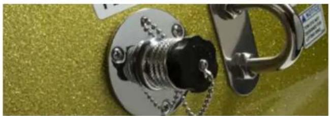
natural_image
Close-up of a metallic keychain and U-shaped lock on a textured surface (no text or symbols visible)Models
Available as an option on all boats. There are two different types of flushes and the installed option will depend on the boat model.
Purpose
Boats that will be operated in salt water (or brackish fresh water) need to be rinsed after every use, including internal engine parts where water has been drawn.
Location
The engine flush connection is on the transom, but varies on different models.
Operation
The engine flush connection allows for quick and easy connection to a shore-side garden hose or similar hose to quickly and easily flush the engine. See the ILMOR Engine Owner's Manual for additional details regarding this important function. The flush connection is located on the transom.
Troubleshooting
If a hose will not connect to the flush connection, locate a different hose. Garden hoses work fine as long as the hose end is not bent or misshapen.
If water will not enter through the flush connection, disconnect the hose and check that there is no obstruction in the connection area.
If there is no obvious reason for the system malfunction, take the boat to an authorized MasterCraft dealer for assistance.
HEAD AND TOILET SYSTEM
natural_image
White toilet with lid and side-mounted base (no text or symbols visible)Model
X26, as an option
Purpose
The on-board head provides convenience for longer outings.
Location
The head is located forward of the observer seat, accessible through a door that opens into the walk-thru area to the bow.
Operation
This boat is equipped with an Dometic Masterflush electric macerating toilet. The Masterflush toilet has a rugged glass filled nylon twin impeller that instantly draws in the effluent into the macerating chamber where the waste is pulverized by a 10 blade stainless steel
cutting wheel and ejects it into the waste tank on the starboard side of the boat via a short run of premium sanitation hose.
Toilet system start-up
- Turn on fresh water pump switch at the helm side panel.
- Press "Flush" switch and hold for at least 10 seconds.
- Toss several sheets of toilet paper into bowl and repeat cycle. The bowl should completely clear.
Normal flushing
FLUSHING TOILET
Press "Flush" switch (bottom switch) down and hold until waste drains from toilet bowl (about 10 - 20 seconds). This switch activates a macerator pump that siphons water and waste from the bowl, macerates, and propels the effluent to the discharge line/ holding tank.
CAUTION
Do not flush waste with "Dry Bowl" Switch! To maintain proper cleanliness and operation of the toilet and macerator pump, water should be used with every flush.
Toilet operation when connected to tank monitor system
A tank watch monitor is located in the head module on the vanity face. It has LED indicators that show empty, low, medium and full.
Never flush the toilet if the indicator shows the holding tank is full. Empty the waste tank using dockside pump-out or optional over-board discharge (3 miles offshore).
text_image
Dometic Seek MonitorCAUTION
Do not flush foreign objects! Flush only water, bodily wastes and rapid-dissolving toilet tissue. Do not flush wet wipes, sanitary napkins, condoms, diapers, paper cups, cotton swabs, food, hair or liquids such as oils or solvents as clogging or damage to the toilet or toilet system may occur.

CAUTION
Hazard of Flooding If toilet is connected to ANY through-the-hull fittings, ALWAYS close seacocks when toilet is not in use (even if boat is unattended for a brief period). All passengers MUST be instructed on how to close valves when the toilet is not in use. Failure to do so can result in flooding which can cause loss of property and life.
NOTE: Make sure all guests understand toilet operation before use.
To empty the waste holding tank
Dockside pump out
The dockside pump out connection is located on the starboard side forward deck in front of the windshield.
- Open the deck plate
- Dock/or fit suction hose from the pump out station or marina into the deck plate.
- Turn on suction pump and monitor the tank level fullness on the waste tank monitor in the head compartment.
- Turn off pump when the monitor reads empty.
The pickup goes to the bottom of the tank and will get most but not 100% of the waste out of the tank.
The tank is protected with Vacuum relief valve do prevent the tank from imploding from dockside pumps the generate huge vacuums.
Optional Overboard Discharge
The boat may be equipped with optional overboard discharge system. The allows the waste to be pumped out the bottom of the boat if you are more than 3 miles offshore on in an area where it is legal to dump waste. Check your local regulations to be sure.
- Open the overboard shutoff valve located under the center floor locker hatch in the walkthrough area of the boat.
-
Lift the starboard side bow lounge seat in front of the driver.
-
Insert key into pump switch panel located under this seat.
- Turn the key clockwise and hold to operate the discharge pump. The switch is spring loaded and must be held to run the pump.
- Run the pump until the tank level monitor reads empty.
- Close the overboard shutoff valve.
- The overboard discharge pump is located in the same area as the key switch, under the starboard side bow lounge seat in front of the driver.
Cleaning the toilet
To maintain the toilet's original appearance, use Dometic® Toilet Bowl Cleaner or other non-abrasive bathroom and toilet bowl cleaners. Please follow label directions.
Caution To avoid damaging internal seals, do not clean toilet with abrasive cleaners, caustic chemicals, or lubricants and cleaners that contain alcohols or petroleum distillates.
Routine maintenance
MONTHLY
- Inspect toilet, plumbing, and plumbing connections, wires, and wire connections.
- Open and close all plumbing valves, including seacocks.
- Check in-line water filters and vented loops for blockage.
YEARLY
Check water valve filter. Also check water valve filter if water flow into toilet becomes insufficient.
During extended periods of non-use
The macerator toilet and sanitation hoses should be protected if toilet will not be needed for an extended period of time (more than two weeks, especially in hot weather).
- Flush toilet and add 4 oz. (118 ml) of liquid biodegradable laundry detergent (should NOT con tain bleach or environmentally harmful substances). Note: If using sea water for flushing, shut off power to sea water pump and add fresh water directly into the bowl during the flush cycle.
- Flush toilet at least five times.
- Turn off water supply to toilet.
- Flush the toilet without water very briefly to evacuate all water. (This procedure will minimize any remaining water in the macerator pump.)
- Turn off power to the toilet.
- After extended periods of non-use, toilet and pump may dry. For easier re-start of toilet system, add one quart of water to bowl and let it stand for a few minutes before use.
CAUTION
During water evacuation process, do not operate sea water pump very long without water. Pump impeller may become damaged.
Winterizing Toilet System
At the end of each season, the macerator toilet should be winterized for storage by using potable water-safe antifreeze (if boat will be exposed to freezing temperatures).
If system will be subjected to freezing temperatures, please follow procedures in this section, "During extended periods of non-use", and then winterize system as described here.
NOTE: Use nontoxic antifreeze designated for potable water systems.
Fresh water system
- Drain potable water tank and empty holding tank.
- Add freshwater antifreeze to potable water tank.
- Flush potable water antifreeze and water mixture through toilet(s) and into entire system, including the waste holding tank, diverter valve connections, discharge pumps, etc. Turn off power to toilet. Each installation is different, so amounts may vary. User discretion is required to assure adequate protection.
CAUTION
Never use automotive-type antifreeze in freshwater systems.
Special Attention
Use only rapid-dissolve toilet paper with these head systems, and only deodorant specially formulated for this type of head system. See the manufacturer's instructions for details. In the event that anything from the head's bowl or holding tank escapes, it should be cleaned as soon as practicable. Failure to clean any spillage may result in unpleasant odors, mildew, mold and damage to the deck or other areas of the boat. This is not covered under warranty.
Trouble Shooting
If the toilet flushes but the water in bowl empties slowly or not at all, then check the discharge piping for kinks and blockages, and the macerator pump for blockages. If the macerator pump makes unusually loud noises, or continually trips the circuit breaker, then check the pump for foreign material. If the toilet doesn't flush after pushing the flush switch, check the tank to see if it is full, check the circuit breaker has tripped and needs to be reset. If the toilet doesn't receive water when the flush button is pushed, check the water supply line to make sure it isn't kinked and the water valve screen to make sure it isn't blocked. If the toilet still exhibits issues, then present the boat to and authorized MasterCraft dealer for repair.
REMOVABLE COOLERS
natural_image
Close-up of a white foldable device with a black handle and screw base, placed on a black tray (no visible text or symbols)Models
All models.
Purpose
The coolers allow for boaters to bring food and beverage on-board for outings and keep such items at a lower temperature than ambient air, and from spoilage as rapidly as would otherwise occur.
Location
Vary by model. See the Guide to Individual Models in this Owner's Manual to determine the location in your model.
Operation
In using the cooler, ensure that the lid is securely closed prior to operation of the boat. If the lid is not secure, water, ice and food/ beverage items may become dislodged and spill into the void where the cooler is stored. Be sure to keep the cooler in the designated location as shown in the Guide to Individual Models in this Owner's
Manual. Coolers that are placed in any other location, including on the deck, are not secure. While the coolers themselves have minimal weight, if they contain ice, food and beverage, the combined weight could cause injury if the cooler moves around during boat operation.

CAUTION
Coolers should always be stowed in the appropriate designated location of the boat as noted in the Guide to Individual Models section of this Owner's Manual. Stocked coolers can have enough weight to cause imbalance in the boat and/or cause injury upon contact.
NOTE: 2015 and newer models have shock assisted cooler cushions to eliminate the need to hold the cushion up while removing and installing the cooler, as well as accessing the cooler for beverages/food. The shock could have reduced performance if the cooler cushion is saturated with water. Also, if the seat hinges become misaligned, and the shock interferes with the clearance
hole, suspect damaged hinges or potentially a deformed substrate/seat base.
Special Attention
As with any similar Igloo-type cooler, routine cleaning with warm soapy water is advised after each use. Check also whether anything from inside the cooler has been spilled or in some manner ended up in the storage area in which the cooler is kept. This should be cleaned up immediately to avoid mold, mildew, stains or other damage that is not covered under warranty.
Food items or anything that can create an odor should not be left in the cooler, nor should anything that can leak be left in these units as they could potentially damage the cooler, and this type of damage is not covered under warranty.

CAUTION
Clean the cooler (and the storage compartment in which the cooler is stored) after each outing in which the cooler was used. Failure to do so can cause damage that is not covered under warranty.
Additional Special Attention
Do not drink water from melted ice or water that is not in containers. The cooler may contain contaminants.
REFRIGERATION
natural_image
Red and white photo of a black rectangular electronic device with a small label, placed on a red surface (no visible text or symbols)Model
X26, as an option
Purpose
The refrigerator is suitable for cooling food and beverages. If you wish to cool medicine, please check with a pharmacist to determine whether the cooling capacity is sufficient for the medicine in question.
Location
The refrigerator unit is located immediately aft of the driver's seat, replacing some storage
Operation
The refrigerator operates by opening the cool box drawer and turning the thermostat knob clockwise. Shutting it off requires turning the thermostat knob counterclockwise. A booklet from the manufacturer is also supplied in your owner's packet. Please review it prior to operating the refrigerator for the first time.
Special Attention
Note that the refrigerator functions off the boat's electrical system. Attention should be paid to the voltmeter(s) to be certain that these systems do not over-drain the electrical system.
Additional Special Attention
Food items or anything that can create an odor should not be left in the refrigerator or cold plate areas. Neither should anything that can leak be left in these units because they could potentially damage the units, and this type of damage is not covered under warranty. The condenser on the refrigerator should be kept free of dust, dirt and anything that inhibits its proper operation. The manufacturer also recommends leaving the door slightly open if it will not be used for an indeterminate period of time. This helps prevent unpleasant odors from forming. Refrigerator cleaning instructions have been provided by the manufacturer. Note that it should always be OFF, and should never be cleaned under flowing water or submerged in any kind of body of water. Do not use abrasive cleaning agents. If it is necessary to defrost the interior, never remove layers of ice with hard or sharp tools because they can damage the plastic of the vaporizer. Allow the unit to air defrost.
Troubleshooting
If the refrigerator will not turn ON and cool, check the main circuit breaker box to ensure that the electrical circuit powering the refrigerator has not tripped. Re-set as necessary. If the system still does not work or continues to trip, take the boat to an authorized MasterCraft dealer.
If the refrigerator stops working during an outing, move any items inside to a cooler. The cooling inside the fridge will last for a short time, but items that require cooling to keep from spoilage may not be kept at a proper temperature for long enough. Foods or medicines that require cooling but have been in the refrigerator without it operating for a period of time should be discarded without use.
MasterCraft assumes no responsibility for spoilage resulting from an inoperable refrigerator or failure to follow directions in use of the refrigerator.
WET BAR
Model
X26, as an option
Purpose
The wet bar offers an area in which fresh water can be accessed, as well as allowing water to be conveniently drained.
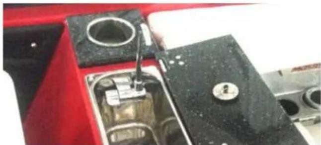
natural_image
Close-up of a red industrial machine component with a black base and mechanical parts (no visible text or symbols)Location
The wet bar is located immediately aft of the driver's seat.
Operation
For the wet bar, ensure that there is water in the freshwater tank. (See Shower and Wash Down information elsewhere in this section of the Owner's Manual.) Flip over the lid that tops the sink to allow access to the sink area. The knobs turn as they do on land-based faucets. Note that the water is not pressurized so it will come out of the faucet with less force than it would ashore. The sink drains through the boat's bilge system.
Water available is limited to the amount in the freshwater tank water from the body in which you are boating is not brought aboard through this system.
Ensure that the faucet is OFF and the lid secured prior to operation of the boat. Leaving the lid up while underway can result in damage that is not covered under warranty.
Special Attention
As noted in the Shower and Wash Down information, and in the Storage and Winterization section of this Owner's Manual, it is extremely important to ensure that there is no water in the freshwater system, which includes the wet bar, during extended storage (at least two weeks without use). Failure to drain the water can result in foul odors, mildew and mold, or other damage that is not covered under warranty.
Additional Special Attention
If other liquid beverages beyond water are poured down the sink, flush with water to avoid the potential development of unpleasant odors which can develop after the system has not been used for an indeterminate amount of time.
Troubleshooting
If no water is forthcoming when the faucet is turned ON at the wet bar, verify that there is still water in the freshwater tank. Also, verify that the circuit has not tripped on the main circuit breaker board. If there is water available and the electrical circuit is functional but the system still does not work, have an authorized
MasterCraft dealer check the system because the pump is inaccessible to consumers.
If the sink does not drain, verify that there is no visible obstruction.
If none is evident, take the boat to an authorized MasterCraft dealer
for service. NEVER pour drain opener or any caustic substance down the drain or otherwise try to open a clog. This can cause significant damage to the system, which is not covered under warranty.

CAUTION
DO NOT pour any drain opener or caustic substance down the wet bar drain. Do not use a plumber's snake or other device to try to open a malfunctioning drain. Any obstruction that is not clearly visible must be removed by an authorized MasterCraft dealer only. Any other attempt to open the drain will likely result in damage to the system that is not covered under warranty.
STORAGE SPACE

natural_image
Interior view of a modern office or cinema space with a large display unit containing a patterned object (no visible text or symbols)Models
All
Purpose
Storage space is integrated into all models to allow on board gear to be stored safely while the boat is underway.
Location
Storage areas vary by model. See the Guide to Individual Models section of this Owner's Manual and also check with your authorized MasterCraft dealer to verify the exact locations on your model. Use only designated storage compartments for storage. Using any other space could result in damage to boat equipment and product, stored items and could potentially cause malfunction of boat systems. Items should always be stowed when the boat is underway to avoid the potential for injury from items dislodged or moving around as a result. Use only designated storage areas to stow items. Use of any other space could result in damage to boat systems that is not covered under warranty. Malfunctions of boat systems could also affect control of the boat, which could result in injury or death. Do not overfill storage areas. Do not try to force doors, cushions or other methods of closure because it can result in damage that is not covered by warranty. Pay attention to the total weight allowance for your boat model and do not include items in storage that will exceed that limit, even if such items will fit in the storage compartment(s). Also note that balance is extremely important and the combination of on-board gear and materials plus the combined
weight of persons on-board affects balance. Items and people should be spread out in the boat to ensure safe maneuvering.

WARNING
Food items or anything that can create an odor should not be left in storage compartments. Neither should anything that can leak be left inside because these items could potentially damage the compartment, and this type of damage is not covered under warranty. Storage compartments require periodic cleaning. See Care and Maintenance in this Owner's Manual for additional information.
LADDERS
Models
The X23, X26, X46, and XStar have a bow ladder available as an option. All boats also have an optional swim platform ladder available with Grappa Gold platform selections.
Purpose
Ladders allow for easier boarding of the boat from the body of water. The swim platform ladder should be boarded only when the boat engine is OFF. See Safety section of this Owner's Manual for additional details regarding carbon monoxide poisoning. (The engine's emissions are at the transom.
Location
Ladders are located at the bow or under the swim platform aft.
Operation
All ladders have a stowable position and an operational position. On the bow ladders, the ladder is stowed inside the anchor locker. The locker is opened by turning the inset latch and pulling open the door. The ladder pulls up and slides out, extending over the nose of the boat. It will latch into place for use. To return it to the locker, refold the sections and place back inside. Close the locker door and ensure that it has latched securely into place.
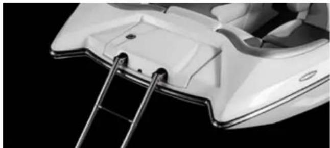
natural_image
Close-up of a white electric scooter's side panel with metal ladder attachment (no visible text or symbols)The swim platform ladder stows under the swim platform. Slide it out and snap into place for use. Re-stow by sliding back under the swim platform.
Be sure to stow ladders prior to operation of the boat. Undue pres
sure from the water while underway could potentially damage the ladder.
Special Attention
When opening or closing the ladder, be careful not to pinch fingers or other skin because all ladders have some kind of catch to hold them in position and provide protection for people as they board.
Troubleshooting
If the ladder will not extend or fold back into stowable position, take the boat to an authorized MasterCraft dealer for repair.
SEATING/BOW LID
natural_image
Interior view of a modern electric vehicle seat with white leather seats and black frame (no visible text or symbols)Models
ProStar, as an option.
Purpose
Bow seating is standard. The ProStar boat may come with an optional bow lid. This lid provides aesthetic appeal to the boat and pays homage to the great tournament towing boats of yesteryear.

CAUTION
When boats are in motion, operators and passengers should always be seated on upholstered, designated occupant seating. No other areas should be used during operation, including, but not limited to, the gunwales, towers, sun pads, engine boxes, or any area that is not clearly intended for seating while the boat is underway.
People can become dislodged from locations that are not actual seating, which could result in falls in the boat or overboard, resulting in serious injury or death.
Boats equipped with the bow lid have storage space beneath it, accessible from the walkway between the helm and observer dashes. No more than 300 total pounds of gear should ever be placed in this storage compartment. Failure to maintain proper weight balance in the boat can lead to a loss of control that can result in serious injury or death.
Location
Bow of the ProStar model.
natural_image
Abstract geometric sculpture with symmetrical angular forms and diagonal lines (no text or symbols)Operation
For boats so equipped, carefully read the Seating information which follows immediately in this Owners Manual. Important safety information is included in that section. Care must always be taken to avoid blocking the view of the boat operator when the boat is underway. All individuals in the boat must be seated and weight properly distributed to avoid complications that can result in serious injury or death. The lid is not intended to be used as additional seating. Allowing individuals to move about or sit on the lid could result in damage to the lid that is not covered under warranty.

WARNING
All boats have weight limits. Failure to adhere to the posted limits can cause operation instability and/or the boat to sink. This may
result in serious injury or death, as well as significant damage to the boat, which will not be covered by warranty.
Special Attention
In the center of the bow is an anti-skid walkway to the bow tip. This is provided to allow swimmers access to the body of water. Individuals should use this walkway only when the boat is stopped and the engine is OFF. Walking on the walkway or exiting the boat from the bow nose at any time when the boat is running could result in an individual falling from the boat, or being run over by the boat. This could result in serious injury or death!
Additional Special Attention

DANGER
Never allow individuals to walk on the bow walkway or anyone to exit the boat from the bow tip unless the boat is stopped and the engine is OFF. Failure to adhere to this instruction could result in serious injury or death!
SEATING
Models
All
Purpose
Comfortable seating is a hallmark of MasterCraft. Not only does the seating enhance the overall boating experience, but it also is the designated area for operators and passengers to occupy while the boat is underway.

DANGER
When boats are in motion, operators and passengers should always be seated on upholstered, designated occupant seating inside the deck and bow areas. No other areas should be used during operation, including, but not limited to, the gunwales, towers, sun pads, engine boxes, or any area that is not clearly intended for seating while the boat is underway. People can become dislodged from locations that are not actual seating, which could result in falls in the boat or overboard, resulting in serious injury or death.
Location
All models have seating inside the deck area and bow area. Some boats also have seating on the sun deck, convertible seating, and optional walk-thru area jump seats. Verify with your authorized MasterCraft dealer the extent to which the seating is considered acceptable for use while the boat is underway.
Operation
Some specialized, optional seating adds more comfort. Convertible seats allow the seat back to be moved forward or back, changing the orientation. (Be sure that the seat back locking mechanism is securely engaged before using the seat back in these types of seating. Failure to engage the locking mechanism may allow unintended movement that could result in a person losing balance or even falling.) The convertible seat backs at the transom are intended to be used only when the boat is stationary and the engine is OFF. The seat back must be in the stowed position, never aft facing, when the engine is running or the boat is underway. Positioned aft facing, the seat back offers no security to persons seated at the back of the boat and they could slide off and into the water, with the possibility of making contact with the transom or swim platform, which could result in injury. Also, while the seat back is positioned to allow aft seating, individuals may be exposed to carbon monoxide if the engine is running.

DANGER
Carbon monoxide is a colorless, tasteless, odorless and poisonous gas that accumulates rapidly and can cause serious injury or death. Exposure to carbon monoxide can be fatal in a matter of minutes. Exposure to even low concentrations of carbon monoxide must not be ignored because the effects of exposure to carbon monoxide can build up and be just as lethal as high concentrations.
Carbon monoxide from exhaust pipes of inboard or outboard engines may build up inside and outside the boat in areas near exhaust vents, particularly during slow-speed operations. STAY AWAY from these exhaust vent areas, which are located at the stern of the boat when the boat engine is running.
Optional jump seats also have latches to hold them in place. Open the observer seat adjacent to the jump seat and note that there is a lock pin that should be inserted to hold the jump seat secure against the side deck of the observer seat. Failure to do this could allow the jump seat to move during boat operation, which could result in passenger injury.

CAUTION
Aft-facing seat backs at the transom or sun pad should always be in the stowed position when the boat is underway. Anyone seated facing aft could become dislodged when the boat is underway, which could result in sliding off the seating and making contact with the transom or swim platform. Jump seats should be secured against the deck with a lock pin accessible under the observer seat to avoid dislodging passengers while the boat is underway. Removable seat backing should always be secured prior to use. Care should be taken to avoid pinching fingers or other skin when sliding the backing or securing/removing the removable seats.
natural_image
Interior view of a modern car dashboard with white seats and orange accent panel (no text or symbols visible)Special Attention
In models equipped with a judge's seat, the observer seat must always be closed prior to any adjustments to the judge's seat back rest, including installing or removing the seat. Failure to close the observer seat can result in damage to the observer seat upholstery. Such damage may not be covered by the warranty.
Special Attention
In some models, removable cushions are available as an option. In those instances, regardless of where the cushions are custom-built to be placed, they will be constructed of the same materials as the rest of the upholstery material. That means that they will require the same cleaning and care. (See Care and Maintenance upholstery information in this Owner's Manual.) Removable cushions should also be stowed in storage when the boat is underway unless they are snapped into position. Failure to stow or snap removable cushions could result in the cushion being lost overboard.
Another attractive feature on some boat models is the folding arm rest, normally found in the bow section. These arm rests are padded with attractive upholstery material, which requires the same type of care as all of the boat's upholstery. (See Care and Maintenance upholstery information in this Owner's Manual.)
GAS ASSISTED SEAT LIFT
Models
X2, X10, X20, X23, X26, X30, and XStar, as an option
Purpose
Allow the helm seat to raise and lower ×3" to accommodate different operator seat height preferences.
Location
Helm Seat
Operation
Lift the handle on the seat pedestal located on the outboard side of the pedestal. To raise, lift handle and remove body weight and the seat will extend up. To lower, lift handle while applying weight to the seat to compress the gas assisted mechanism inside. Release handle between the topmost and lowest position to set and hold the seat height.
CONVERTIBLE CENTER REAR SEAT
natural_image
Interior view of a car seat with leather seats and side panels (no visible text or symbols)
natural_image
Interior view of a car dashboard seatbelt with no visible text or symbolsModels
X10, X20, X23, X26, X30, X46 and XStar, as an option
Purpose
Allow the option of occupants to sit forward facing, rear facing or create a center cockpit sunpad.
Location
Aft section of the cockpit.
Operation
The seat has a sliding/locking pivot connecting the seat back to the seat cushion.
Forward to Rear Facing and vice versa: Lift sharply up on the handle at the top of the seat back to lift off the "Lock" position. Hold the handle while lifting the seat back up and away from its current
position at the same time. The seat cushion will then lift and rotate. Continue pulling forward until the seat cushion rotates past vertical. Then lower the handle and press the seat back down toward the cockpit floor as the seat cushion comes to rest 180 degrees from its previous position. This will reengage the seat back "Lock"
Rear Facing to Sunpad: When the seat is in the rear facing position, lift sharply up on the handle at the top of the seat back to lift off the "Lock" position. Hold the handle while rotating the seat back toward the bow of the boat. The seat back will rotate and lay down on braces in the cockpit to create a full sunpad.
Sunpad to Rear Facing: Lift and rotate the handle on the seat back. When the seat back is vertical, press the seat back down toward the cockpit floor as the seat cushion comes to rest 180 degrees from its previous position. This will reengage the seat back "Lock".
REMOVABLE REAR SEATS
natural_image
Interior view of a car's front compartment showing wood trim and dashboard (no text or symbols visible)Models
ProStar, as an option
Purpose
Two removable rear seats allow additional passengers to be transported in the boat. The seats can be removed when not needed.
Location
Aft section of the cockpit, port and starboard.
Operation
Removal: Lift the forward edge of the seat bottom. Rotate up and pull forward at the same time. Two hooks on the seat back will release from eyelets connected to the rear deck wall. When released, lift seats out of the boat and store.
Installation: Set the seat on the cockpit floor near the aft cockpit wall. Lift the forward edge of the seat bottom. Slide the seat rearward until the seat back hooks touch the aft cockpit wall just blow the eyelets. Set the seat bottom down slowly, ensuring that both seat back hooks pass through an eyelet.

CAUTION
Never operate the boat without the rear seats installed properly. Seat back hooks firmly captured by the eyelets and all four foot pads sitting on the cockpit floor.
SURF SLEEVES
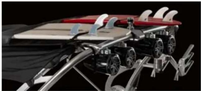
natural_image
3D rendering of a futuristic robotic vehicle with curved surfaces and mechanical components (no visible text or symbols)Models
All boats with ZFT4 or ZFT5p towers.
Purpose
Surf sleeves allow surf boards to be stowed during boat operation without taking up additional space on deck. This is particularly convenient for surf boards which do not fit in storage compartments.
Location
Surf sleeves are on top of Bimini canvas.
Operation
Slide surf boards inside one of the four pockets and snap the protective strap to secure each board. Always secure the surf boards
with the straps and fully inserted the sleeves because boards can become dislodged and fall onto the deck, potentially harming passengers. Never tow with surf boards in the surf sleeves, even if the straps are snapped. The kind of force on the system could cause the straps to break and allow the boards to come out of the sleeves.

WARNING
Never tow over the road with anything in the surf sleeve, even with the straps connected. Wind and air currents can be sufficient to break straps and/or force the surf boards or other items to dislodge. This could result in damage to vehicles following and/or serious injury or death to individuals in those vehicles.
natural_image
Close-up of a metallic mechanical component with a cylindrical top and lever mechanism (no visible text or symbols)Models
X2, X10, X20, X23, X26, X30, X46 and XStar, as an option
Purpose
The video cable ensures correct GoPro camera placement by displaying on the 7" dash a live stream of what the camera is actively recording. Connecting the video cable also makes it possible to control the camera's angle and zoom settings while it is mounted to the boat tower.
Location
Cable attachments are located in the glovebox or observer seating area.
Operation
Connecting a GoPro camera to the MasterCraft 7" video screen for the first time requires a few initial steps that make it simple to display live action in the future.
Step 1: Pair a GoPro Camera (not supplied) with an Apple Device (not supplied)
a. Download and install the free GoPro app from the iTunes store (one time only)
b. Turn on the Apple device Wi-Fi from the list of available Wi-Fi connections
c. Turn on the GoPro camera
d. Open the GoPro app on the Apple device
e. Go to Settings in the GoPro app and follow the on-screen prompts to connect the GoPro camera to the Apple device
Step 2: Connect Apple Device to Boat HDMI Adapter
a. Attach the Apple Lightning to USB Cable (not supplied) to the Apple device
b. Take the Apple device to the glovebox and attach the USB end of the Apple Lightning to USB Cable to the supplied Lightning to HDMI Adapter
c. Plug the Lightning to HDMI Adapter into the HDMI port on the HDMI/USB panel that is mounted in the glovebox
d. Plug the USB end of the Lightning to HDMI Adapter into the USB port on the HDMI/USB panel that is mounted in the glovebox
Step 3: 7" Screen Set-Up
a. Push the Video button on the 7" screen
b. Select Tower as the Video source.
NOTE: The following items are user supplied and not included with a MasterCraft boat
- Apple device, only models with Lightning connector such as iPhone5, and newer iPad/iPad Mini
- Apple Lightning to USB cable
- GoPro camera, only models with Wi-Fi capability, such as Hero3 with Wi-Fi backpack or Hero4
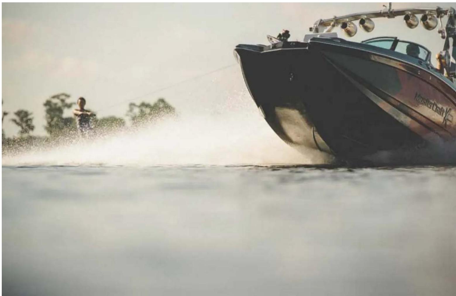
natural_image
RCA motorboat with water splashing, person wading nearby (no visible text or symbols)PREPARATION
$$ \frac{1}{2} = \frac{1}{2}\left( \frac{\ln x}{2} - \frac{\ln y}{2} \right) + \frac{1}{2}\left( \frac{\ln z}{2} - \frac{\ln y}{2} \right) $$
PREPARATION
USING CARE WHEN FUELING
natural_image
Close-up of a metallic wrist strap with blue and white stripes (no text or symbols visible)MasterCraft boats are equipped with a highly innovative fuel system. This system is designed to provide years of trouble-free service. Some of the latest innovations related to fuel handling safety are also incorporated into the fuel delivery system.
The fuel pump system in your boat was specifically designed for the marine environment and contains a number of added safety components that are unique to the marine environment. Because of the special nature of the design, there are no user-serviceable parts. Any parts in need of service or maintenance will need to be addressed by an authorized MasterCraft dealer. An authorized MasterCraft dealer is equipped with the special tools necessary to disassemble and service the fuel capsule and associated parts. Replacement parts must meet OEM requirements as specified by MasterCraft.
The fuel line in the bilge area that goes from the tank to the engine is a special multi-layer armored line that is covered with a special material known as a fire sleeve. The fire sleeve affords protection to the fuel line in the unlikely event of a boat fire. The sleeve is colored orange for easy identification of the fuel line.
During the first time the fuel tank is filled, the process will be very slow. Air is being displaced in the system. In all subsequent fuel-filling, the process will take about the same amount of time as it does to fill a land-based vehicle.
During refueling you should reasonably expect to avoid having any fuel spit-back or well-back when using an automatic shut-off fuel pump nozzle. All land-based gas stations in North America are required to use these; some marinas may not. Therefore, we recommend that you never leave the fuel fill unattended when fueling.
MasterCraft also recommends daily inspection of the bilge for foreign materials and the possibility of gas or oil leakage detection. As part of your daily inspection, include a visual check of the orange fire-sleeved fuel line. If you see damage to the sleeve or line or in any way suspect damage or fuel leakage,
DO NOT START THE BOAT! Immediately call an authorized MasterCraft servicing dealer and let him or her assess the situation. Even if it results in the outing being canceled, leaking fuel can cause serious damage to the environment and may be a potentially hazardous situation for people and property in the area. Therefore, it is critical to attend to any indication that there is fuel line damage or fuel leakage as soon as possible.

DANGER
Gasoline is extremely flammable and highly explosive under certain conditions. Always stop the engine and never smoke or allow open flames or sparks within fifty (50) feet of the fueling area when fueling.

DANGER
Take care not to spill gasoline. If gasoline is spilled accidentally, wipe up all traces of it with dry rags immediately and dispose properly on shore.

DANGER
Gasoline is explosive. If a gasoline odor is present or gasoline is visually observed in the bilge area during inspection, DO NOT START YOUR ENGINE! If the engine is already
running, press the START-STOP button to stop the engine. Remove the ignition key from the ignition switch and call an authorized MasterCraft dealer for service.
FUEL LEVELS
Starting the engine with fuel levels below the acceptable standard will likely cause damage to the fuel pump. MasterDraft, working in conjunction with the fuel pump manufacturer, has determined that on initial (first-time) use, the boat should have a minimum of fifteen (15) gallons of gas. This will prevent fuel starvation in instances of extreme running angles or sloshing away from the fuel pick-up. Note that continuous wake surfing port or starboard with low fuel in the tank will starve the pump of fuel and cause it to either seize or overheat and blow fuses. The boat should never be used for wake surfing at less than one-quarter (1/4) tank full of fuel.

CAUTION
Allowing the fuel level in the fuel tank to fall below one-quarter of a tank full may affect the reliability of the fuel pump or result in damage to the fuel pump, which is not covered under warranty.

natural_image
Person performing a high kick on water, mid-air with ropes and motion lines, no visible text or symbolsILMOR MARINE ENGINES
WHAT TYPE OF GASOLINE TO USE
MasterCraft boats are equipped with ILMOR Marine Engines, the finest quality power plant in the industry. ILMOR supplies an Owner's Manual with the purchase of the boat. Additional, very critical information regarding the proper use of gasoline in relation to the ILMOR Marine Engine is contained in the engine owner's manual, including but not limited to:
• What type of gasoline to use
- Avoiding oxygenated fuels or fuels with alcohol
• What to do when the boat is not used for a while
• Fueling outside the United States and Canada.

CAUTION
Damage to the engine by use of low-quality gasoline or gasoline with an octane rating below the minimum level listed for ILMOR MV8 engines will void the warranty on the engine.

CAUTION
Extended storage with fuel in the system can affect fuel stability and may require system inspection and fuel filter replacement when the boat returns to service.
Troubleshooting the Fuel System
Fuel Pump Does Not Run When The Engine Start-Stop Button Is Pressed
Cause 1
Pump may not be receiving sufficient voltage to the pump, or there may be corrosion interfering with the electrical impulse.
Remedy 1
Take the boat to an authorized MasterCraft dealer. Only the dealer has the specialized, required tools to correct the problem.
Cause 2
The fuel pump relay may be flipped at the engine fuse block.
Remedy 2
Reset the relay.
Potential Cause 3
Both of the two in-line fuses between the fuel pump and the engine may have blown.
Potential Remedy 3
Fuses will need to be replaced.
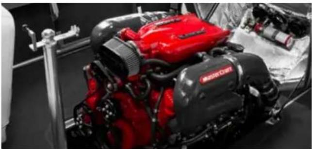
natural_image
Close-up of a red and black MGRC engine component on display, no visible text or symbolsThe Sound Of The Fuel Pump Running Is Audible But The Engine Does Not Start
Cause
The system may have inadequate fuel pressure or clogged fuel filter and/or lines.
Remedy
Take the boat to an authorized MasterCraft dealer. There are a variety of potential causes that can negatively impact fuel pressure. All repairs require specialized tools available only to dealers.
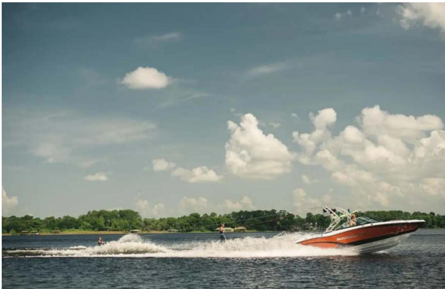
natural_image
Speedboat with water splashing on a lake under a cloudy sky, with trees and distant buildings in the background (no visible text or symbols)SAFETY CHECKS AND SERVICES
The following checks and services are essential to safe boating and must be performed. Get in the habit of performing these checks in the same order each outing so that it becomes routine.

CAUTION
DO NOT launch or operate the boat if any problem is found during the Safety Check. A problem could lead to an accident during the outing, resulting in death or serious injury. Any and all problems should receive attention immediately. See your authorized MasterCraft dealer's service department for assistance.
Before Each Operation
These tasks are best accomplished before the boat is launched.
- Follow all engine and drive train pre-operation maintenance and safety
- Checks as outlined in the provided engine owner's manual.
- Check the weather report, wind and water conditions.
- Check for recommended on-board tools and parts.
- Check that all drain plugs are installed properly, including bilge and rear drain.
- Check the propeller and shaft for damage.
- Check that there is an adequate supply of fuel.
- Check that the steering system operates properly.
- Check that required safety equipment is on board.
- Check that the windshield and extrusions do not show any damage.
When boating, avoid using the windshield as an aid for balance or getting out of a seat. This causes undue stress to the window frame and could damage it, which may not be covered under warranty.
- Check that the fire extinguisher is fully charged.
- Check that no fuel, oil or water is leaking or has leaked into the bilge compartment.
- Check all hoses and connections for leakage or damage.
- Check that everything is secure, tower and mirror knobs are tightened, all latches and brackets are secure, and anything that might move around in the cockpit during operation has been stowed. Even soft objects can cause injury when underway, Under normal operations, there will be some vibration, and this may loosen hardware over time.
- Check that all required Scheduled Maintenance Checks and Services (see following sections) were performed.
During Operation
- Check gauges frequently for operating conditions.
- Pay attention that controls operate smoothly.
• Note any excessive vibration. - Check that everything is secure, tower and mirror knobs are tightened, all latches and brackets are secure, and anything that might move around in the cockpit during operation has been stowed.
stowed. Even soft objects can cause injury when underway. Under normal operations, there will be some vibration, and this may loosen hardware over time.
- Check that all required Scheduled Maintenance Checks and Services (see following sections) were performed.
After Operation
- Check for fluid leaks.
In boats equipped with a ballast system, drain water from the ballast system before placing the boat on the trailer. If the boat has ballast-pumping assistance to remove water from the ballast system, note that the engine must be running at least 1500 RPM during the pumping process (for both fill and empty operations). This will necessitate draining water prior to ceasing operation of the boat and loading on the trailer. More information regarding ballast systems appears in various sections of this Owner's Manual, but pay particular attention to the information under Boat Operations.
- Check the fins (where equipped), propeller, rudder and shaft for damage after removing the boat from the water.

natural_image
Two people surfacing on a floating platform with water splashing, under a cloudy sky (no text or symbols visible)NEW BOAT BREAK-IN
The first fifty (50) hours of operation are the most important for establishing acceptable wear parameters for the boat. Proper break-in will ensure maximum performance and the longest possible power-train life. The break-in period allows moving parts within the engine and transmission to wear-in properly. All Master-Craft boats are lake-tested on the water before leaving the factory, but the break-in must continue for the first fifty (50) hours of your ownership.

CAUTION
To ensure proper break-in and lubrication, boat owners should not remove the factory break-in oil until after the initial ten (10) hours of operation and before twenty-five (25) hours. At that time, an oil change should be performed on the Ilmor engines by an authorized Ilmor/ MasterCraft dealer.
Failure to follow the break-in procedure exactly as stated will void the engine warranty!
NOTE: Before operating the boat for the first time, you must read the engine manufacturer's manual completely in addition to this Owner's Manual!
Please follow the break-in procedure carefully. Close attention to the following is very important:
Maintain the proper oil level.
Until the piston rings, cylinder and other working internal parts are thoroughly seated, oil consumption can be high and must be carefully watched. (This continues to be important after break-in, as well).
Pay close attention to the gauges and video screen(s).
It is important to stop the engine immediately if the gauges and/or video screen(s) indicate a problem. Low oil pressure and
overheating are serious issues and require immediate attention.
Abnormal vibration or noises.
These symptoms can be the first signs of trouble and should not be ignored. Occasionally, hardware may work loose, mountings may need to be tightened or the drive line may require attention.
Fuel, oil or water leaks.
Leaks can pose a serious safety threat. If one occurs, it is quite likely to do so after a few hours of operation.
Vary the engine speed.
Never run the engine for more than three (3) minutes at any constant RPM during the break-in period. Following this specific instruction will assist in the proper break-in of rings and bearings.
Plane the boat quickly.
Operating the boat at low speeds places an excessive load on the engine. Plane quickly, then back down to a slower speed.
First Hours of Operation
The first hours of operation affect the engine and drive train more than any other component on the boat. Therefore, it is very important to follow EXACTLY the break-in procedure as outlined in the engine owner's manual.
Engine manufacturers have detailed and specific requirements for proper engine break-in. That information is found in the engine manual supplied, and must be followed exactly as indicated. Failure to do so could cause engine damage and/or failure that is not covered under warranty.
After Break-In
Once the break-in period is over, the boat may be operated continuously at any speed, but not beyond the maximum indicated in the engine owner's manual.
The engines are equipped with rev-limiters which will cause a fluttering when reached. If the boat has the correct propeller set-up, operators should never reach the limiter, but if that happens, it is a signal that you should reduce the throttle and check with an authorized MasterCraft dealer to determine the cause. Always remember that during normal operation you should allow the engine to warm up gradually. Be sure the engine is warm before accelerating. Pay careful attention to the gauges and video screen(s). Also, check the oil level frequently during the first fifty (50) hours of operation since the piston rings and cylinders require that much time to seat properly.
See the Scheduled Maintenance Checks and Services section for more details.

CAUTION
Failure to follow the engine oil recommendations listed in the engine owner's manual can cause additional engine wear and increase the possibility of engine component failure. Damage to the engine due to incorrect oil usage can be costly to repair, and it is not covered by the warranty!

natural_image
Two people swimming in water with a red inflatable boat in the background under a blue sky (no text or symbols visible)STARTING AND BASIC OPERATIONS
NOTE: If you are operating this boat for the first time, you must follow the engine and drive train break-in procedures as described in the engine owners manual. Failure to follow these procedures may result in serious damage and may void any warranties!
Before Starting
Familiarize yourself with the controls and indicators used on this MasterCraft boat. Perform all Safety Checks and Services as described in that part of this section of the Owner's Manual. Also perform all Scheduled Maintenance Checks and Services as described in this Owner's Manual.
Step 1
Lift the engine cover and inspect the bilge and engine compartment for any fluid/vapor leakage. MasterCraft recommends lifting the engine compartment cover for inspection before each use.
Step 2
Check the hull drain plugs. Make sure they are installed and secure.
Step 3
Operate the bilge blower for at least four (4) minutes. Leave the bilge blower ON through the starting process and until the boat is on plane.

DANGER
To prevent a possible explosion, operate the blower for at least four (4) minutes before starting the engine and always when at idle or slow-running speed. Explosive gasoline and/or battery fumes may be present in the engine compartment. Failure to do so may result in serious injury or death!

DANGER
Before starting the engine, open the engine compartment and check for gasoline fumes, fuel and oil leaks or the presence of fuel or oil in the bilge.
NOTE: Always start the engine with the control lever in the neutral position or with the shift disengaged. Your boat is equipped with a neutral- start safety switch that will not allow the engine to be started when in gear.
Starting the Engine
Attach the emergency engine safety switch tether (lanyard) to an article of your clothing and to the switch.
All models will have a removable ignition key. Its purpose is for safety and security. The key should be inserted prior to starting an outing, and removed at the conclusion. This is intended to prevent theft or unapproved use of the boat.
The process for starting the boat is:
- Insert the key and turn. This turns ON the electrical system and prompts the battery(ies) to provide power.
- Momentarily press the ENGINE START-STOP button.
NOTE: While the engine is warming up, check to see that all lights, video screens and gauges operate properly. Check that the steering system operates freely. There should be no apparent leaks
under pressure. Reengage the control lever after warm-up by returning the lever to neutral and pushing the throttle button back into the engage position.
Shifting Gears
When shifting gears, always move the control lever smoothly and quickly into gear. Do not hesitate. Slow gear engagement could damage the shifting mechanism in the transmission.
NOTE: When shifting from forward to reverse or reverse to forward, be sure to stop the control lever in the neutral position and allow the engine to fall between 600-800 RPM before completing the shift.
A one-hand, single-lever control operates as both a gear shifter and a throttle. The lever automatically locks in the neutral position (straight up and down) for safety. The lever can be moved from neutral only by raising the umbrella lifter under the ball knob. Shifting is accomplished by moving the lever forward or backward. Center (straight up) is neutral. Moving the lever forward engages the running gear; moving it back from center puts the drive train into reverse. Never attempt to shift without the engine running! This causes excessive wear to the shifting mechanism and may negatively affect control of the boat.
During regular warm-up of the engine, it is possible to temporarily increase the engine RPMs without moving the boat. To accomplish this, push in the button located at the bottom of the shift/throttle lever with one hand and pull up the "umbrella" (umbrella lifter under the ball knob). Move the lever to desired position and
then simultaneously release the button and umbrella. The engine will run with increased RPMs and can be increased or decreased by moving the lever. Returning the handle to the neutral position will bring the system back to neutral and reduce the engine RPMs to preset levels. This function should be done sparingly. Over-revving the engine for any extended period can cause undue wear and tear on the engine. Avoid advancing to wide-open-throttle and holding the RPMs at that level.
Under Way
If the oil pressure gauge indicates low or no oil pressure, immediately stop the boat as outlined below and check the oil level. If the temperature gauge indicates overheating, stop the boat when it is safe to do so as outlined below and check the raw water system for blockage. (See the Boat Operations and Care and Maintenance sections of this Owner's Manual for directions on how to properly check for the blockage.) DO NOT operate the boat until the cause for the warning has been found and corrected.

CAUTION
Continued operation after the warning light has illuminated may cause severe engine damage. This will void your warranty.
Stopping
- Step 1: Slowly bring the control lever to the neutral position. If the boat has been driven for a long period of time or at high speed, allow the engine a two-to-three (2-3) minute cool-down period at low idle (600-800 RPM).
- Step 2: Press the ENGINE START-STOP button.
- Step 3: At the conclusion of the outing, turn the key off and remove from the key slot. Turn the battery switch to "Off". Doing so will ensure that you have turned OFF the electrical system, and prevent others people from starting or running the boat.
- Step 4: If any problems were encountered during operation, have the boat inspected by an authorized MasterCraft dealer. Request any necessary repairs before resuming operation of the boat.
OPERATIONAL HINTS
MasterCraft urges all who will be operating the boat to seek certified instruction from the local boating authorities. This section is designed to present the most basic operational principles. It is NOT intended to cover all conditions encountered during operation. Therefore, the principles presented in this Owner's Manual are limited to the facts related directly to the operation of the boat, while the responsibility for the proper application of these principles belongs with the boat owner and/or operator.
Loading the Boat
Never overload the boat. The maximum weight capacity as listed on the certification plate includes all items added to the boat (including persons and gear). Proper distribution of weight is critical to boat performance. Allocate the load as evenly as possible. The maximum weight capacity includes filled, factory installed ballast tanks and/or ballast bags, as well as any added by the customer.
The maximum weight capacity is calculated with full factory-installed fuel and ballast tanks. The weight of occupants, gear and water in any ballast bags added by the customer reduces the Maximum Capacity of the boat. Failure to adhere to the total Maximum Capacity may result in too much strain on the drive train or may sink the boat. This is not covered under warranty! See the Common Sense Approach information in the Safety section of this Owner's Manual regarding weight.

WARNING
Adding supplementary aftermarket ballast to a MasterCraft boat is not recommended, and can result in impaired visibility, diminished handling characteristics and instability when operating your boat. Such condition may result in potential structural and/or engine damage to the boat, which damage will not be covered by your warranty.

DANGER
Information regarding the Maximum Capacity for each boat is included in the Guide to Individual Models section of this Owner's Manual and on a placard located near the operator's position. It is the boat operator's responsibility to ensure that the boat is never overloaded. Too much additional weight may cause the boat to overturn or sink, which can result in serious bodily injury or death.
Emergencies
Know how to use and spot distress signals, and to offer assistance if possible. Remember, you may need assistance someday. Review the Safety section of this Owner's Manual.
Courtesy
Always respect the rights of others on the water. Keep wide when passing, slow down in crowded areas, be alert and be aware of your wake and wash. See the Rules of the Open Water information in the Safety section of this Owner's Manual.
First Time Operation
When taking to the water for the first time, you must keep in mind a few general guidelines:
Practice makes perfect! Start in calm water with no wind or current and plenty of room until you get the feel for the boat and its controls.
Proceed slowly! Give yourself time to think, react and maneuver.
Recognize outside forces! Check the wind direction and velocity, as well as water currents and waves.
Have a crew on hand! Have friends or family ready with fenders, lines and a boat hook to assist you when docking, as well as launching and loading.
Remember that a boat is not an automobile! Boats cannot be maneuvered and stopped like a car. Boats steer from the stern (rear) and have no brakes.
Basic Maneuvering
Steering response is dependent upon three (3) factors: rudder position, motion and throttle. While cruising speed maneuvering is relatively easy and takes little practice, slow-speed maneuvering is far more difficult and requires time and practice to master.
With both steering and propulsion at the rear of the boat, the initiation of a turn pushes the stern of the boat away from the direction of the turn. The stern follows a larger turning circle than the bow.
This is especially important to remember when making maneuvers within close quarters.
While the effects of unequal propeller thrust (torque steering), wind, and current may not always be present, a practiced driver will use them to his/her advantage.
Unequal thrust is a phenomenon shared by all single-engine, propeller-driven boats. With the rudder in the straight-ahead position, a counterclockwise rotation propeller tends to cause the boat to drive to port when going forward, and to starboard when going backward.
At high speed, there is compensation for this effect, so that unequal thrust is virtually non-existent. But, at slow speed—and especially during backing—the effect can be very pronounced. This is the main reason that most experienced drivers approach with the dock to the starboard side of the boat.
Stopping—or checking headway—is a technique that must be mastered. With no brakes, reverse must be used to stop the boat. The momentum of the boat will vary according to the load. Make it a practice to slow to in no-wake speed before shifting into reverse.
When practicing maneuvering techniques, always do so in open water that is free of traffic. Adequate practice may make the difference between a pleasurable boating experience or a potentially damaging (at the very least, embarrassing) one.
High Speed Operation
MasterCraft boats are designed to accommodate professional drivers with advanced operating skills who can perform high-speed maneuvers and turns on-a-dime. DO NOT attempt to duplicate or simulate these feats. Paid, professional drivers log thousands of hours on the water and carefully choreograph every move. Plans are made in advance in the event the routine must be aborted.
Maneuvers of this nature could cause serious injury or death, as well as damage to your MasterCraft boat that will not be covered under warranty.

DANGER
Boat operators should never attempt to duplicate operational skills of professional drivers. When such maneuvers fail, it can result in serious injury or death.
For the best engine performance and longevity, the wide-open-throttle (WOT) engine operation must be near the top of, but within, the specified WOT operating range. To adjust the WOT operating range, select a propeller with the proper diameter and pitch. The propeller supplied on the boat was chosen for best all-around performance under average operating conditions.
Load, weather, altitude and boat condition all affect WOT engine operation. If the boat is used for several different applications such as wakeboarding, barefooting and cruising, it may be necessary to have two (2) or more propellers of differing size and pitch to allow the engine to operate in the WOT range for each application.
Propping the boat should be done after the boat is loaded in the manner in which it would normally be loaded for each application. For example, in propping the boat for wakeboarding, fill the ballast tanks and add the people and gear that normally would be expected
in the boat. Take the boat out and after warm-up, run it at wide-open-throttle and note the maximum RPM. EFI engines are equipped with RPM limiters to prevent over-rewing. Take note if the RPM limiter is activated.
If the WOT RPM is higher than the maximum RPM in your engine's WOT operating range, the boat is under-propped. Installing a higher-pitched propeller will reduce the WOT RPMs. An engine that is over-revving may quickly experience catastrophic damage, which will not be covered under warranty.
If the WOT RPM is lower than the minimum RPM in your engine's WOT operating range, the boat is over-propped. Installing a lower-pitched propeller will increase WOT RPMs.
An engine that is under-rewing is "lugging." This places a tremendous load on the pistons, crankshaft and bearings and can cause detonation, piston seizure and other engine damage, which will not be covered under warranty.

CAUTION
Engines should always be operated within engine manufacturer guide lines. Failure to do so may cause significant damage to the engine and drive train and is not covered under warranty!
Elevation and weather also have a very noticeable effect on the wide open throttle power of an engine. Since oxygen gets thinner as elevation increases, the engine begins to starve for air.
Humidity, barometric pressure and temperature have a noticeable effect on the density of air since heat and humidity thin the air.
This phenomenon can become particularly apparent when an engine is propped for use on a cool, dry day in spring and then is operated on a hot, humid day in summer, and does not have the same performance. Although some performance can be regained by dropping to a lower-pitch propeller, the basic condition still exists. The propeller is too large in diameter for the reduced power output. An experienced marine dealer can determine how much diameter to remove from a lower-pitch propeller for specific high-elevation locations.
MasterCraft's engine manufacturer suggests that consumers consult with the dealer from whom the boat was purchased regarding the best propeller for the application in which the boat will primarily be run. However, be aware that changing the propeller may void the warranty. Again, working with an authorized MasterCraft dealer is your best bet to ensure excellent performance.
Unusual Operating Conditions
If the body of water is unknown, talk to local boaters about the type of obstacles that may be encountered beneath the water's surface. Rocks, tree stumps and sandbars are all dangerous and damaging. Be especially wary of rivers and man-made lakes. Rapidly changing conditions can cause daily changes in underwater hazards.
Stay well clear of floating debris. What looks to be a small branch in the water may well turn out to be an entire tree.
When traveling through weedy areas, keep an eye on the engine temperature gauge. Weeds caught up and blocking the water flow through the raw water intake or transmission cooler will cause trouble. Also, after leaving the weedy area, shift to neutral for a few seconds and then to reverse for a few seconds to unwind any weeds that may have wrapped around the propeller.
Docking and Tie-Up
Approach the dock slowly, with the starboard side of the boat if possible. The natural tendency to torque steer with the rotation of the propeller at slow speeds makes docking easier on that side. Also, use wind and current to your advantage when docking.
Before tying up the boat, be sure to use enough dock bumpers to protect the boat from damage. If possible, tie-up with the bow toward the waves. Use good quality double-braided nylon line. Tie-up only to the cleats or tie-down eyes. Never use the handrails or ski pylon.

CAUTION
Boats left at docks or at anchor must be monitored on a regular basis to avoid sinking. Maintain adequate battery charge to operate the bilge pumps to avoid excess water intrusion. If leaking is detected, immediately remove the boat from the water and determine the cause.
If the boat is to be moored for a long period of time, use chafing protectors to protect the gel coat finish. Leave a little slack in the lines, allowing for some wave movement or tidal action where applicable. If the boat is to be kept in or near water for the season, consider the purchase of a boat lift and bottom paint for the hull. These lifts prevent the build-up of marine growth on the hull as well as protecting the boat from damage typical of on-water storage, such as blistering. Make sure the boat lift supports the hull correctly. See the next section, Lifting the Boat information in the Care and Maintenance section of the Owner's Manual.
CARE AND MAINTENANCE
$$ \frac{1}{2} = \frac{1}{2}\left( \frac{\ln x}{2} - \frac{\ln y}{2} \right) + \frac{1}{2}\left( \frac{\ln z}{2} - \frac{\ln y}{2} \right) $$
LIFTING THE BOAT
When the boat is hoisted from the water, proper use of the stern eyes or a sling system is required for all MasterCraft models. Though stern eyes are designed to lift a boat from the water, care must be taken to ensure you do not damage your boat. A spreader bar used at the stern, will help ensure that the load at the stern eyes is vertical. A strap placed between stern eyes, and then lifted from the mid-point, is not the recommended method, and will put substantial additional stress on the stern eye mounting location.

CAUTION
DO NOT use the ski pylon or any portion of any tower for lifting. They are NOT designed to be used as a central lifting point. Also, DO NOT use the stern ski tow as a lifting ring. The deck may be damaged. Never use the cleats as lifting points. See the Storage Cradle sub-section of this section. Also never lift a boat with water in the bilge or containing a water-filled device such as a ballast system or sack. The extra stress will put an excessive load on the hull and lifting equipment that may seriously damage the boat. Such damage may not be covered by the warranty.
USING LIFTING EYES
An overhead hoist with an appropriate rating capacity should be used to lift your boat. Cables should be properly rated for each model. Each cable should be rated at or above the full weight of the model to be lifted. When lifting, keep the bow slightly higher than the stern to prevent any possibility of water running into the engine exhaust manifold.
USING LIFTING SLINGS
An overhead hoist with an appropriate rating capacity should be used. Slings must be six (6) inches wide by twenty (20) feet long
and each sling should have a minimum capacity rating that is equivalent to the weight of the model that is to be lifted. Use an eight-foot spreader bar on each sling to prevent damaging side pressure to the deck or gunwale molding.

CAUTION
Lifting slings must never contact shafts, struts or hardware protruding from the hull. Damage may result that will void the warranty.

CAUTION
When the boat is out of the water, it is important to support the hull correctly to avoid any hull damage. Such damage may void the warranty.
STORAGE CRADLE
If a storage cradle is used, the hull must be properly supported to prevent load damage. This can occur with as little as fifteen (15) pounds per square inch of pressure. DO NOT support the boat by resting the hull on the keel (the central fore-and-aft structural member in the bottom of the boat's hull, extending from the bow to the stern). Vertical supports must extend from the chine (the angular intersection of the bottom and sides of the boat) to the keel with no gaps between the hull and cradle supports. A total support area of at least 500 square inches is required for proper support of boats under 25' and 600 square inches for boats over 25'. Protect all items extending from the hull (i.e., the rudder, propeller, fins, etc.) to prevent them from resting on the cradle or the ground. DO NOT apply any load stress to the propeller, shaft, rudder, swim platform, water intake grate or other protruding items.
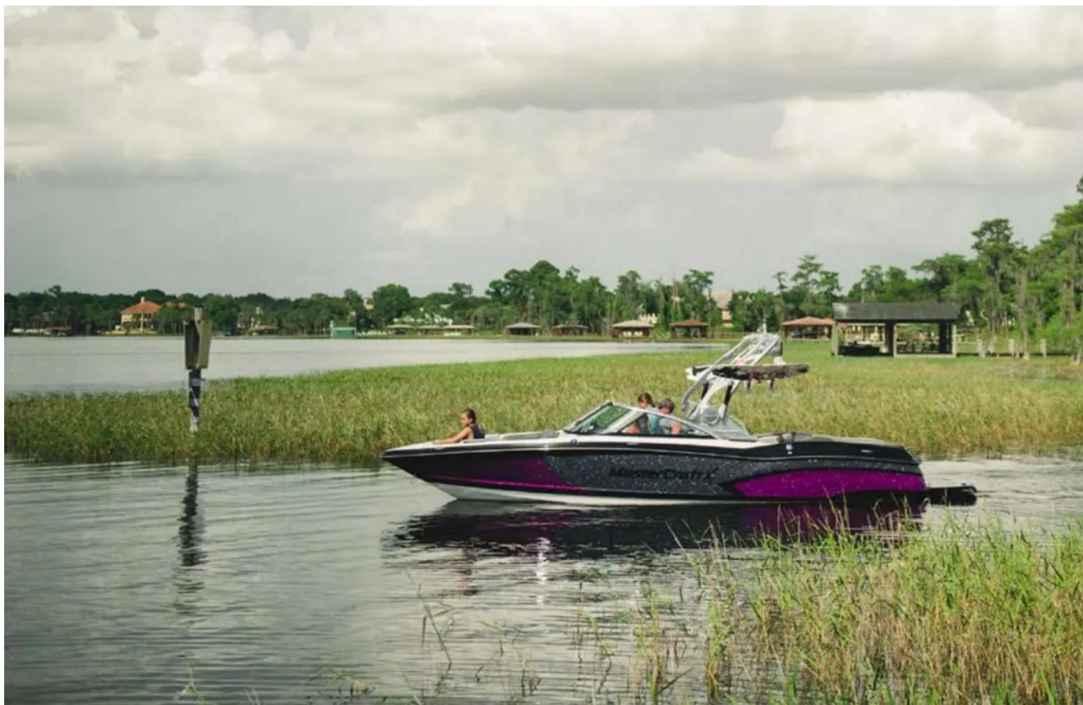
natural_image
Exterior view of a purple and black jet boat on a lake with people in the water, surrounded by reeds and greenery under cloudy skies (no signage or text visible)CORROSION PREVENTION
NOTE: DAMAGE DUE TO CORROSION IS NOT COVERED UNDER WARRANTY!
GALVANIC CORROSION
natural_image
Close-up of a metallic mechanical component with two circular holes, held by fingers (no visible text or symbols)Galvanic corrosion (electrolysis) to the boat is the decomposition of metal due to the effects of electrolytic action. When two (2) dissimilar metals are immersed in a conductive fluid (e.g., salt water), an electric current is produced, much like the action of a battery. As the current flows, it takes with it tiny bits of the softer metal. If left unchecked, severe damage may occur over time. If the boat is operated in salt, polluted or brackish waters, even temporarily, the boat should be equipped with a transorm-mounted zinc anode to prevent damage to those metal parts coming in contact with salt water.
The zinc is, by design, self-sacrificing. It is slowly eroded away by electrolytic action and requires periodic inspection for deterioration. When the zinc has eroded to approximately one-half (1/2) of its original size, it must be replaced to continue protection, or damage to other metal parts may result.
MasterCraft Saltwater Series boats come equipped with the zinc anode. For fresh water boats that may be operated in polluted or brackish water, an authorized MasterCraft dealer can provide guidance in securing and installing a zinc anode for protection.
SALT WATER CORROSION

natural_image
Close-up of multiple smartphone screens displaying blue liquid, arranged in a grid pattern (no visible text or symbols)The boat has been designed for operation in fresh water unless it is a model in the MasterCraft Saltwater Series. If operating a fresh-water model temporarily in salt, polluted or brackish water, thoroughly flush the boat with fresh water as soon as possible afterward. The entire engine cooling system should be flushed with fresh water for at least ten (10) minutes after each use in such waters.
Boats operated continuously in salt water should be equipped with a closed cooling system to preserve engine life.
MARINE GROWTH
natural_image
Close-up of a red and black boat hull partially submerged in water, with splashing water and green trees in the background (no text or symbols visible)If accelerated marine growth is a problem in the area in which the boat will generally be operated, an anti-fouling bottom paint may be necessary to slow growth while protecting the gel coat. Before selecting a bottom paint, talk with other boaters and an authorized MasterCraft dealer's service department to determine the product that works best in the area. Many local variables may also affect the selection of paint. Be sure to follow the paint manufacturer's directions exactly.
STAINLESS STEEL AND CHROME/ ANODIZED ALUMINUM
Stainless steel, chrome-plated and anodized aluminum parts are not totally resistant to corrosion. Occasional cleaning and polishing with a marine chrome-and-stainless polish will maintain and extend the life of these parts. In salt water areas, it is imperative that you thoroughly rinse all hardware with fresh water and apply a light coating of protective oil to enhance the appearance after each use. Exposure to salt water will cause corrosion leading to significant damage to stainless steel, chrome and anodized aluminum parts. Failure to thoroughly rinse salt water from all hardware, and to apply
protective oil after each exposure to salt water, will accelerate the corrosion of hardware and will void your warranty.
natural_image
Close-up of a metallic cylindrical mechanical component with a circular logo on its side, set against a red background (no readable text or symbols)
CAUTION
Be sure all fasteners used are approved and rated for marine use. Most fasteners used on MasterCraft boats are stainless steel or specially coated to resist corrosion.

WARNING
Use of improper parts may cause component or engine failure. Such failure may result in death or serious injury!
CAUTION
Exposure to salt water will cause corrosion leading to significant damage to stainless steel, chrome and anodized aluminum parts. Failure to thoroughly rinse salt water from all hardware, and to apply protective oil after each exposure to salt water, will accelerate the corrosion of hardware and will void your warranty.
CLEANING THE BOAT
Periodic cleaning is the best way to keep your boat looking like new. Regular washing and waxing keep dirt and build-up from deteriorating the finish. If you keep your boat in showroom-new condition, then your personal satisfaction will be higher and the resale value of your boat will be greater.
The boat is made of fiberglass-reinforced plastic resin material that is easy to clean and care for. Several layers of resin material are chemically bonded together to form the hull. The smooth outside surface of the hull is a layer of gel coat resin. The gel coat is a solid color that is only a few millimeters thick.
Beneath the gel coat surface is a series of layers of chemical resin, fiberglass mat and woven roving. It is these layers that give the boat its strength and maintain the hull shape. The boat bottom also uses special coremat material for its strength-to-weight and superior marine performance.
Even though MasterCraft has carefully crafted boats from resilient materials, it is still the responsibility of the boat owner to perform regular and routine cleaning maintenance to ensure that the boat exterior, interior and components retain both their appearance and strength.
HULL

natural_image
Abstract red and black decorative pattern with a central golden shape (no text or symbols)When washing the boat, use a mild detergent, such as Dawn or Ivory dish soap, or similar commercially-produced detergent, and warm water solution. DO NOT use abrasive cleaners, solvents, ammonia or chlorine, as these will damage the gel coat surface.
Under extreme conditions, special cleaners may be used to remove marine growth from the hull. (See an authorized MasterCraft service department for further instructions.)
CARPET

natural_image
Close-up of a white textured surface with a metallic grille and black textured base (no text or symbols visible)Occasionally washing with mild detergent and warm water or household carpet cleaners will help keep the carpet clean. Thoroughly hose the detergent out of the carpet and into the bilge. (This is a good time to clean the bilge also.) Allow the boat to remain uncovered to air dry for several days to prevent any mildew or odor caused by moisture.
PLATFORMS
All Wood Platforms
If shoes are worn when walking on the wood, they should be proper boating shoes. Black-soled shoes are likely to scuff the surface, resulting in marks that may be difficult to remove or even leave
permanent marks that are not covered under warranty. Regular cleaning and oiling of wood will maintain its original appearance. Unprotected wood will turn gray and could split or separate. If this happens it may void the warranty.
New wood platforms have been sealed and finished with an oil-based, wood preservative by the manufacturer.
natural_image
Close-up of a wooden board with two hole holes, partially covered by a black metal frame (no text or symbols visible)Platforms will keep the new look and last for many, many years if properly maintained. For best results re-oil the platform and allow it to dry before the first use. If the boat spends a lot of long weekends on the lake with the swim platform in the water or if the platform sits uncovered in the sun, it should be oiled one or two times a month during the first season; then as needed after that. The platform should be covered when not in use or when stored for the winter.
Many products such as boiled linseed oil, tongue oil, wood oil and other outdoor wood preservatives can be found at marinas, paint stores or home improvement stores. Some oils such as linseed oil should be thinned with a thinner like mineral spirits before use. (70 percent oil-30 percent thinner.)
When oiling a platform, apply a coat of oil with a wet cloth, work into the seams, end grain and edges. Allow the oil to set approximately 15 minutes and then wipe off the excess oil with a dry cloth. Do not let the oil dry on the platform in the sun. Excess oil should be removed with a dry cloth.
AquaTrac Platforms
natural_image
Close-up of a metallic vehicle's side panel with blue and silver components (no visible text or symbols)AquaTrac should be handled only with clean hands. Oil, grease or dirt may leave permanent imprints on the surface. Whenever possible, keep the platform covered when the boat is not in use. It should be stored dry.
Spills
Scoop or scrape up as much of the spill as possible, followed by a thorough blotting of the remaining spotting with a dry, clean cloth. If cloth is not available, paper towels are an acceptable substitute.
Non-oil Based Stains
Create a detergent solution by adding 1/4" (one-quarter inch) teaspoon of liquid dish detergent to one (1) cup of warm water. Apply the solution to the affected area (do not scrub) and blot with a dry, clean cloth. Repeat the process until the stain stops transferring to the cloth. If the stain still appears on the platform, apply the solution to the area and allow it to stand for 2-5 (two-to-five) minutes. Then rinse with clear, clean water.
Oil-Based Stains
Apply naphtha-based (hydrocarbon petroleum) solvent or mineral spirits to the affected area and follow the instructions on the solvent container. Use care when using such solvent cleaners as directed on the container instructions as there may be health matters to consider when using these solvents. Always work from the outside into the center of the stain. Do not scrub!
If stains still appear, the surface may be restored by lightly sanding the area with a drywall sponge with 240-360 grit. The sanded area will probably appear slightly lighter than the rest of the platform but should blend into the overall color in time.
Fiberglass Swim Platform
The fiberglass swim platform requires the same kind of regular—and gentle—cleaning that the rest of the boat needs. After cleaning off any environmental debris, wash with mild soap and warm water. Avoid the use of ArmorAll or similar types of rubber-shine products as these will speed the decay of the rubber rather than protecting it.
WINDSHIELD

natural_image
Close-up of a car's front window and side panel, showing interior design (no visible text or symbols)In cleaning tempered glass windshields, the normal glass cleaners (from spray bottles or aerosol cans) work best. While the glass is very strong, it can be scratched if anything abrasive is used. Harsh chemicals or solvents should be avoided because they may affect the vinyl gaskets, anodized or powder-coated finish on the extrusions.
CANVAS COVERS
natural_image
Close-up of a car's roof structure with visible structural components against a black background (no text or symbols)The material used in constructing Bimini tops and boat covers is made from 100 percent solution-dyed polyester fiber with a urethane coating to provide excellent water repellency and mildew resistance. This design allows the material to be easily maintained. By following a few simple care and cleaning steps, the fabric will continue to look good and maintain its fine qualities for seasons to come.
Important Background Information
Because the fabrics are woven, they are breathable. It's also important to know that these fabrics are treated with a fluorocarbon finish, which enhances water repellency. This finish requires replenishment after vigorous cleaning. Polyester fabric will not support
the growth of mildew. Mold and mildew need something on which to grow and polyester fabric is not a desirable substance for such growth. Dirt or dust on the fabric, however, is a perfect source for mildew growth, which makes regular cleaning of the fabric important.
The material has an applied finish that deters mold and mildew growth, but it does not make it mold-proof. Keeping the fabric free of dirt and foreign substances is important in deterring mold growth.
There is no set time for when the fabric should be cleaned, and the local environment has a great deal to do with determining cleaning frequency. Cleaning is required less frequently in a dry environment than in a humid one where heavy foliage exists.
Cleaning
One of the best ways to keep the material looking fresh and new, and to delay the need for deep or vigorous cleaning, is to hose off fabrics with clear water on at least a monthly basis with clear water. This practice will help prevent dirt from becoming deeply embedded in the fabric, and it will eliminate the need for more frequent and more vigorous cleanings.
In most environments, a thorough cleaning will be needed approximately every two (2) years.
The fabric can be cleaned while still in the boat. When cleaning, it is important to observe the following:
• Always use a natural soap—never detergent.
- Water should be cold to lukewarm, but never more than 100 degrees.
- Air dry only. Never apply heat to the fabric. Begin by brushing off loose dirt, and then hose down the material.
Prepare a cleaning mixture of water and a mild, natural soap that is free of detergents. Use a soft-bristle brush to clean, allowing the soap to soak in. Rinse thoroughly and allow the fabric to thoroughly air dry.
If stubborn stains persist, you can use a diluted chlorine bleach/soap mixture for spot cleaning of mildew, roof run-off and other similar stains. Please keep in mind that chlorine bleach will not change the color of the fabric, but chlorine bleach will eventually break down the fiber of any fabric. Therefore, this cleaning method should be used as infrequently as possible.
The cleaning mixture should be mixed as follows:
Four ounces (one-half cup) of chlorine bleach.
Two ounces (one-fourth cup) of natural soap. One gallon of water.
Clean with a soft- bristle brush and allow the mixture to soak no longer than twenty (20) minutes. Rinse thoroughly and allow to completely air dry. Repeat if necessary.
If the top or boat cover is suitable in size for a washing machine, these steps should be followed:
- Use only natural soaps—no detergent.
- Wash and rinse in cold water. Air dry. (Never put the fabric in a dryer.) As part of the finishing process, the material has been treated with a fluorocarbon finish, which enhances water repellency.
This finish is designed to last for several years, but it must be replenished after a thorough cleaning. Based on test results, the manufacturer recommends 303 High Tech Fabric Guard™ as the preferred retreatment product.
After cleaning and air drying, apply 303 in a thin, even coat. When it has dried, apply a second thin, even coat. These two (2) light coatings are more effective in restoring fabric water resistance than a single heavy coating. Keep in mind that 303 High Tech Fabric Guard™ will work only as well as it is applied. This means that the fabric must be free of dirt and detergents or the Fabric Guard will wash away with the dirt particles.
Fabrics should be retreated after thorough cleaning or after five (5) years of use.
ENCLOSED HEAD
An enclosed head is found on the X26 model. This convenience should be emptied on-shore within an acceptable holding tank, septic system or sewer. It should never be emptied within the boating body of water or on-shore, except in an approved receptacle!
The head should be cleaned after each outing. After thoroughly cleaning with a mild detergent, add a neutralizing chemical made
natural_image
White ceramic toilet with lid and side panel (no text or symbols visible)especially for portable heads, such as that found in RV centers. The neutralizing chemical will help deal with potential odors that might otherwise be foul. (See also Head under the Boat Operations section of this Owner's Manual.)
UPHOLSTERY
While the vinyl is made to withstand the elements, it is important to care for vinyl by keeping it clean at all times. Many substances may stain the vinyl if left untreated over a period of time. Remember to remove any contaminant and clean vinyl immediately.
Regular washing with mild detergent (see attached information) and warm water or vinyl cleaners is sufficient to keep the cushion and vinyl coverings in good condition.
text_image
MasterCraftDo not soak the cushion, and dry thoroughly after washing to prevent mildew accumulations when the boat is covered. Spray the cushions with a mildew repellent and prop them up in the boat when it is covered to take advantage of air circulation. MasterCraft vinyl is made to withstand the effects of sun, heat, acid rain and soiling, under normal conditions, but this does not preclude the cleaning requirements. Please consult the following cleaning recommendations before cleaning your upholstery.
In some instances, consumers have reported the appearance of a pink stain on vinyl that is resistant to various cleaning methods. Although there can be other causes for pink staining in vinyls, most pink stains are caused by dyes produced by micro-organisms. These dyes are metabolic products of the micro-organisms, otherwise known as a form of fungi.
natural_image
Interior view of a modern car cabin with white leather seats and steering wheel (no visible text or symbols)It is virtually impossible for consumers to avoid these micro-organisms as they exist in the atmosphere, which are more prevalent in high-humidity areas. Rain cleanses the air, with the result being that the micro-organisms are deposited on items such as marine vinyl.
While the vinyl is treated to resist the growth of micro-organisms (meaning the vinyl is not a food source), the stain results from failure to properly clean and maintain the vinyl. This means that after use, the upholstery must be cleaned with a soft brush and warm soapy water, followed by a thorough rinse with clean water.
This situation is worsened if the boat is stored without proper ventilation or if the boat cover is put on while the vinyl is still wet, creating a situation in which all forms of fungi (mold and mildew) thrive. Failure to follow these instructions in the proper care of upholstery may cause your warranty to be voided!
The cleaning table presented in this section is offered only as a suggestion and as an aid in attempting to deal with stains. We do not guarantee that the cleaning methods will work. Stains from any external source are unlikely to be covered by warranty.
Additional Upholstery Cleaning Information
The following information refers to the performance of the upholstery product in specific tests conducted under laboratory conditions. Results may vary under actual conditions. This information is not a guarantee and does not relieve the user from the responsibility of the proper and safe use of the product and all cleaning agents. The use of certain agents can be harmful to the surface appearance and lifespan of the vinyl. The vinyl manufacturer and MasterCraft assume no responsibility resulting from the use of such cleaning agents to the vinyl. Please check compatibility when using this product in combination with painted or varnished surfaces.
| Common Stains Step 1 | Step 2 | Step 3 | |
| General Care A B | |||
| Dirt build-up A B | |||
| Ballpoint ink* B A | |||
| Chewing gum B A | |||
| Coffee, tea, chocolate B A | |||
| Grease C B A | |||
| Household soil A B | |||
| Ketchup A B | |||
| Latex paint A B | |||
| Lipstick C A B | |||
| Mildew or wet leaves* | B A | ||
| Motor oil | C B A | ||
| Oil-based paint | C B A | ||
| Permanent marker* | B A | ||
| Spray paint | B A | ||
| Suntan lotion* | A B | ||
| Tar/asphalt | C B A | ||
| Yellow mustard | A B |
* Always remove stains immediately. Upholstery must be kept CLEAN AND DRY!
A = Medium soft brush, with warm soapy water. Rinse and dry.
B = 303 Fabric and Vinyl Cleaner. Rinse and dry.
C = Wipe or scrape off excess (chill gum with ice before starting).
All cleaning methods must be followed by a thorough rinse with clean, warm water. Failure to care for your vinyl properly, or the use of improper cleaners, may void your warranty, as well as damage your vinyl.
Certain household cleaners, powdered abrasives, steel wool, and solvent cleaners can cause damage and discoloration and are not recommended. Dry cleaning fluids and lacquer solvents should not be used because they will remove printed pattern and gloss. Waxes should be used with caution because many contain dyes or solvents that can permanently damage the protective coating.
Do not clean with power washers as they can generate 3,500 P.S.I. and could damage the surface of your interior. Do not use kerosene, gasoline or acetone, because they will remove the protective marine top coat. Do not use any silicone based protectants. They will extract the plasticizer, leaving vinyl hard and brittle, and eventually cracking will occur.
Your satisfaction is directly related to regular care of the upholstery!
Vinyl upholstery should be covered when not in use to protect from further sun exposure, tree debris, air pollutants and acid rain.
For storage, vinyl should be cleaned, protected, covered and stored in a dry, well ventilated area.
Recommended Products
- MasterCraft Vinyl Dressing
- Vinyl Finish
- Vinyl Cleaner
- Mild Dish Soap
• 303 High Tech Fabric Guard™
• 303 Fabric and Vinyl Cleaner™ - Babe's Seat Soap
Non-Recommended Products
- ArmorAll
- Bleach
- Baking Soda
- Fantastik
- Formula 409
- Murphy's Oil Soap
- Son-of-a-Gun
- Simple Green
- Anything not listed on the Recommended Products list!
MAINTENANCE SERVICE
FREQUENCY AND SCHEDULED MAINTENANCE
Proper care, maintenance and adjustment will contribute to the peak performance of the MasterCraft boat, while also extending the overall service life and the resale value.
The pages that follow provide instructions on how to accomplish the required checks, inspections and services listed. An authorized MasterDraft service department is the best source for proper maintenance.
NOTE: The engine and drive train require scheduled maintenance checks and services in addition to the boat's other maintenance requirements. Read and understand the engine owner's manual that has been provided, and follow the maintenance schedule to ensure proper operation and quality service over the life of the boat and drive train. Failure to follow the maintenance requirements and instructions listed in this and all other manuals may result in damage to the components, systems and equipment of the boat, which resulting damage will not be covered by warranty! Safety issues are also directly impacted by proper maintenance!
Maintenance Definitions
Check
Verify the operational readiness by physical measurement, i.e.,
measuring the oil level with the dipstick or aligning with a feeler gauge.
Inspect
Determine the operational readiness by examination, i.e., by sight, sound or feel.
Change
Tasks required periodically to keep the boat in proper operating condition, i.e., drain, replenish or service.
NEW BOAT BREAK-IN
NOTE: MasterCraft recommends the following functions be performed by authorized MasterCraft technicians at an authorized MasterCraft dealer.
- Check the alignment of the propeller shaft. (See Annual Maintenance also.)
- Have an authorized MasterCraft service department change the fuel filter after the first fifty (50) hours of operation, and then again at one hundred (100) hours. The fuel filter should be changed annually, even if less than one hundred (100) hours are run during the previous season.
BEFORE EACH USE
Before Starting the Engine
Review the engine manual before each outing to determine the drive train requirements that need to be followed prior to each use.
- Review the Safety Checks and Services section of this Owner's Manual. There are important functions that must be followed before, during and after every outing, without fail!
- Inspect the raw water intake water strainer for blockage. If there is blockage, also check the transmission cooler (where equipped).
- Check and clean as necessary the seacock strainer.
- Check the cooling system level. See the engine owner's manual for details.
- Inspect the battery connections and hold-downs.
- Inspect the drive train for loose or missing hardware.
- Inspect the throttle and shift cables for kinks, wear and interference with other components.
- Inspect the propeller shaft log for excessive water entry.
- Inspect the fuel system lines and connections for leaks.
- Check for water leaks or excessive exhaust odor.
• As you start the engine: - Check that the voltage reading registers a fully charged battery.
AFTER EACH USE
Refer to the Cleaning the Boat and Corrosion Prevention sections of this Owner's Manual for guidance on a thorough approach to maintenance. Also pay attention to the information provided regarding the maintenance of Carapa Gold platforms and accessories because the wood requires periodic maintenance as well.
Boats equipped with an optional flushing system for use in salt water or brackish water should operate the flushing system.
Quarterly (Every Fifty [50] Hours) Before Starting the Engine Or After It Has Cooled
- Check the safety equipment.
- Change the oil.
Annually (Every One Hundred [100] Hours)
NOTE: MasterCraft recommends that the following be performed by authorized MasterCraft technicians at an authorized MasterCraft dealer.
Before Starting the Engine Or After It Has Cooled
- Replace the fuel filter (to be performed by an authorized Master-Craft technician only).
- Check the propeller shaft coupler alignment.
- Lubricate the steering system.
• Lubricate the throttle and shift cables.
- Check the engine mounts.
- Inspect the complete fuel system for leakage.
- Check the fire extinguisher and suppression units on-board.
- Change impellers.
Details follow in the next few sections.
MasterCraft recommends using an authorized MasterCraft technicians at an authorized MasterCraft dealer for many of these tasks!
SCHEDULED MAINTENANCE
Before Each Use
Prior to Starting the Engine
Review the Safety Checks and Services section of this Owner's Manual. There are important functions that must be followed before, during and after every outing, without fail! The Safety Checks and Services notes that all drain plugs must be reinstalled prior to operating the boat!
Inspect Seacock Strainer
Because a clogged seacock strainer puts undue strain on the engine(s), the strainer should be checked prior to starting the boat. The seacock strainer is standard on all boats.
natural_image
Close-up of a black industrial sprayer device with attached tubing and a transparent cylindrical component (no visible text or symbols)Step 1
Open and lift the cover.
Step 2
Remove the filter and inspect for debris. Manually clean the strainer.
Step 3
Check for debris and remove any that is inside the sea strainer.
Step 4
Return the lid and tighten in place.
Inspect the Battery Connections and Hold-Downs
Because poor connections or hold-downs may result in erroneous voltmeter readings, MasterCraft recommends doing this before starting the boat.
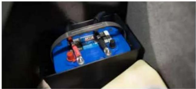
natural_image
Close-up of a blue battery pack with red and black components, held in a white glove (no visible text or symbols)Step 1
Ensure the engine is OFF and the engine safety starting switch disconnected. Be certain that the throttle/shift control lever is in neutral. Locate the battery. Batteries are placed in a variety of locations, depending on the model. Check under the observer seat or behind the rear seat.
Step 2
Check that the battery post connections are clean and tight. If not, loosen and remove the negative terminal connection first. Be careful not to touch the positive terminal with the wrench.
Loosen and remove the positive terminal connection. Remove the battery hold-downs and remove the battery from the boat. Clean corrosion from the battery posts with a battery terminal cleaner. Clean the battery with a water-and-baking-soda solution. Use care to avoid allowing the solution to enter the battery vents. Rinse the battery with fresh water.

WARNING
Battery electrolyte fluid is dangerous. It contains sulfuric acid, which is poisonous, corrosive and caustic. If electrolyte fluid is spilled or placed on any part of the human body, immediately flush the area with large amounts of clean water and immediately seek medical attention.
Use a battery terminal cleaning brush to remove corrosion from the inside of the battery terminals. Clean the terminals with a water-and-baking-soda solution and rinse with fresh water.
Check the battery box that normally holds the battery in place to determine whether there is evidence of battery fluid inside it. Battery fluids are corrosive and can cause permanent damage to the battery box. If fluid is evident, wash out the box with the water-and-baking-soda solution that is used in cleaning the terminals. Rinse with fresh water and dry with a cloth.
Reconnect the positive terminal first, then the negative. Tighten the terminals. Coat both terminals completely with a thin covering of marine dielectric grease. Be sure that the rubber boot covers the positive terminal completely.
NOTE: The boat's engine is designed to work with the standard electronics installed in the boat. Adding other electrical components or accessories can change the way the fuel injection controls the engine or the overall electrical system functions. Before adding electrical equipment, consult an authorized MasterCraft dealer's service department. Otherwise, the engine may not perform properly.
CAUTION
Add-on equipment may adversely affect the alternator output or overload the electrical system. Such damage may not be covered by the warranty.
If a replacement battery is required, be certain to select a marine battery with at least seven-hundred-fifty (750) cold-cranking-amps at zero degrees ( 0^ ) Fahrenheit. Before disconnecting the battery, make sure the ignition key and all accessories are in the OFF position. Also remember to re-attach the cables in the proper order, with the positive cable connected to the positive [+] post and the negative cable connected to the negative [-] post.

WARNING
When charging, batteries generate small amounts of dangerous hydrogen gas. This gas is highly explosive. Keep all sparks, flames and smoking well away from the area. Failure to follow instructions
when charging a battery may cause an electrical charge or even an explosion of the battery, which could result in death or serious injury.
MasterCraft recommends the use of a spiral-cell type battery, such as the Optima brand. These batteries exceed other batteries in holding and extending a charge.
INSPECT THE THROTTLE AND SHIFT CABLES FOR KINKS, WEAR AND INTERFERENCE

CAUTION
Some engine parts become very hot during operation. This inspection must be completed while the engine is cool to prevent burns to your skin. Perform this task before starting the boat.
Step 1
Ensure the engine is OFF, the engine safety starting switch is disconnected and the throttle/shift control lever is in neutral.
Step 2
Open the engine compartment and locate the throttle and shift cables. Follow each cable back under the floorboards and feel for
any kinks and wear on the outer jacket. Any sign of cable damage is cause for replacement. See your authorized MasterCraft dealer's service department if you notice any cable damage.
This function should be performed prior to starting the engine; and then again after about three (3)-to-five (5) minutes to determine whether any leaks are apparent.
Step 1
Ensure the engine is DFF, the engine safety starting switch is disconnected and the throttle/shift control lever is in neutral.
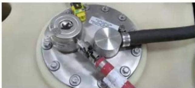
natural_image
Close-up of a metallic mechanical component with a black cable and red connectors, no visible text or symbols.
DANGER
Gasoline is highly flammable and its vapors may ignite, resulting in fire or explosion. Be sure to keep all sparks and flames away from the area while inspecting the boat's fuel system.
Step 2
Open the engine compartment and visually check as much of the fuel system from the tank to the engine as you can see. On some models this is will be a limited area. If the odor of gasoline is strong or if you see visual evidence of fuel outside the system, cease all operations and take the boat immediately to an authorized MasterCraft dealer's service department to determine the source of the leak. The leak must be repaired before the engine is restarted. Because the lines on late model MasterCraft boats are pressurized, they can be disconnected and/or removed ONLY by using specialized tools.

WARNING
The engine box serves as a machinery guard. The engine must be OFF whenever the box is open. Clothing for body parts can get caught in moving parts, causing death or serious injury. Keep away from moving parts!
This is important! Fuel leakage can lead to a build-up of potentially explosive fumes within the engine compartment. DO NOT IGNORE OR OVERLOOK THIS INSPECTION AND REPAIR AS NECESSARY!
NOTE ANY EXHAUST ODORS
This function should be performed prior to starting the engine; and then again after about three (3)-to-five (5) minutes to determine whether any leaks are apparent.
Step 1
First ensure that the engine is OFF and that the engine safety starting switch is disconnected. Be certain that the throttle/shift control lever is in neutral. The engine must be cool.
Step 2
Open the engine compartment and note whether there is any unusual odor. In many instances, exhaust will have little or no odor, but in the event of a potentially significant exhaust leakage, it may be possible to smell a "rotten-egg" odor that signifies a probable issue that must be addressed.
Step 3
If leakage is apparent, tighten the hose clamps, being careful to avoid crimping the hose. If the leakage is significant, or is occurring at a location other than the joints (such as a split in a hose), see your authorized MasterCraft dealer's service department for parts and service.
This is important! Exhaust fumes can cause illness or impairment, including carbon monoxide poisoning. Equally important to consider, leakage can lead to a build-up of potentially explosive fumes within the engine compartment.
DO NOT IGNORE OR OVERLOOK THIS INSPECTION! REPAIR AS NECESSARY!
BEFORE EACH USE After Starting the Engine
Check That The Battery Is Fully Charged
As the boat is started, check all gauges, but pay particular attention to the voltage. (On all models, press the Gauge soft key on the left side of the touch screen to access this information.)
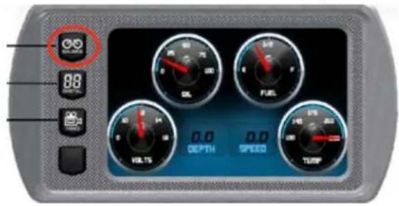
While starting the engine, check that the voltmeter reads between 12.4 and 14.5 volts. An erratic reading may be a sign of low voltage. The voltage reading is the best indication of the of your battery. However, it is not fool-proof. While the reading may indicate that the battery is producing current, if during a previous operation you had reason to suspect a problem with your battery, check with an authorized MasterCraft dealer's service department.
Current models are equipped with a low-voltage battery alarm. In the event that the stereo has been functioning when the boat engine is OFF, the voltage drain on the battery may result in difficulties restarting the boat. To avoid this situation, when the voltage level falls to 10.5 volts, the system will shut off the stereo system and sound an alarm for a period of two (2) minutes to allow the operator time to turn the ignition key ON and start the engine. Doing so will allow the engine's alternator to recharge the battery.
Charge dead batteries with a battery charger before attempting to start the engine. (Some MasterCraft models offer an optional battery charger; but never jump-start the battery.) Jump-starting from another boat or battery is dangerous! Charging a dead battery from an engine will put undue stress on the alternator, which may cause it to fail.

WARNING
When charging, batteries generate small amounts of dangerous hydrogen gas. This gas is highly explosive. Keep all sparks, flames and smoking well away from the area. Failure to follow instructions when charging a battery may cause an electrical charge or even an explosion of the battery, which could cause death or serious injury.
CAUTION
Crossing cables or jumper cables may result in damage to the electrical components due to incorrect battery connections. Such damages may not be covered by your warranty.
Repeat Check For Fuel And/Or Exhaust Leaks
This function should be performed after about three (3)-to-five (5) minutes of running the engine to determine whether any leaks are apparent.
natural_image
Close-up of a red industrial machine component with a circular logo (no readable text or symbols)
natural_image
Close-up of a metallic mechanical component with bolts and a red-and-white tool inserted (no visible text or symbols)After three (3)-to-five (5) minutes of operation, shut down the engine and ensure that the engine safety starting switch is disconnected. Be certain that the throttle/shift control lever is in neutral. Again, inspect the fuel system as well as possible. Inspect the fuel pump gasket, fastener gaskets, regulator seal and sender gasket for leaks. If the odor of gasoline is strong or if you see visual
evidence of fuel outside the system, cease all operations and take the boat immediately to an authorized MasterCraft dealer's service department to determine the source of the leak. The leak must be repaired before the engine is restarted. Because the lines on late model MasterCraft boats are pressurized, they can be disconnected and/or removed ONLY by using specialized tools that are not available to the public.
Reinspect after the fuel tank has been filled full for the first time of the season.
Note that fuel systems vary by model. The pump-in-tank location on top of the fuel tank will resemble one of the two adjacent photos.
This is important! Fuel leakage can lead to a build-up of potentially explosive fumes within the engine compartment. DO NOT IGNORE OR OVERLOOK THIS INSPECTION AND REPAIR AS NECESSARY!
Also, recheck that there is no unusual exhaust odors as described prior to starting the engine.
AFTER EACH USE
General Cleaning And Storage
Refer to the Corrosion Prevention and Cleaning the Boat sections of this Owner's Manual. After each outing, the boat should receive a general cleaning and drying prior to being stored. Even if the boat is
kept in a slip, owners/operators should wipe down the interior and should periodically remove the boat from the water for a general cleaning.
In instances of boats being left moored in water, it may be necessary to periodically run the bilge pump to clear out water that has intruded into the bilge compartment. Keep the battery fully charged in order to be able to provide this function.
Inspections
As noted in the Before Each Use section, some functions there need to be performed following use of the boat, such as checking the intake strainer or seacock strainer if evidence has shown that debris collects during the outing. Wet debris is often easier to remove.
SCHEDULED MAINTENANCE
QUARTERLY- EVERY FIFTY [50] HOURS
Check Safety Equipment And Change Oil
Throughout this Owner's Manual, boat owners, operators and users have been reminded to pay particular attention to any and all safety requirements.
At the fifty (50) hour mark, it is appropriate to check that all required and recommended safety equipment be reviewed for condition and repaired or replaced as necessary. This includes all personal flotation devices. It is also advisable to check that all equipment and personal items onboard have been properly stowed and the routine maintenance performed.
These efforts are in your best interest!
ANNUALLY - EVERY ONE HUNDRED [100] HOURS
MasterCraft recommends that your annual—or one hundred (100) hour—maintenance requirements be performed by an authorized
MasterCraft dealer. The staff there has the proper equipment and technical training to best meet your service needs
Annual Maintenance
Some boat owners choose to personally execute some maintenance procedures on their boats. MasterCraft has provided information on several procedures. For safety reasons, a few must be performed by authorized MasterCraft service technicians only, such as anything involving checks and repairs on the fuel line, which is under pressure, and replacement of impellers.
These matters must be addressed on a regular basis, at one hundred (100) hours or annually, whichever comes first, and these procedures are in addition to seasonal preparation and winterization (see Storage and Winterization section for additional details). All of these issues are extremely important to continued boating pleasure, as well as long life for the boat, and the critical matter of safety.
Even if the annual maintenance work is completed by an authorized MasterCraft service technician, boat owners and operators should still review this section and ensure that they have some understanding of what is necessary to keep the boat in top condition.
CHECK THE ENGINE MOUNTS

CAUTION
Some engine parts become very hot during operation. This inspection must be completed while the engine is cool to prevent burns to your skin. Perform this task before starting the boat.
Step 1
Ensure the engine is DFF and disconnect the engine safety starting switch. Be sure that the throttle/ shift control lever is in neutral. The engine must be cool.
Step 2
Open the engine box and locate the four (4) motor mounts.
natural_image
Close-up of a mechanical component with a metallic cylindrical body and a small protruding part, no visible text or symbols.Step 3
Check the tightness of the mounting hardware and adjustment lock-nuts. Tighten any loose hardware securely.
CHECK THE PROPELLER SHAFT COUPLING ALIGNMENT
This function is critical to avoiding unnecessary wear and potential damage to the engine as well as the propeller and propeller shaft. Because it is a complex and exacting part of maintenance, this should be performed only by your authorized MasterCraft dealer as part of your annual maintenance.
INSPECT THE EXHAUST FLAPS FOR DAMAGE
natural_image
Close-up of a metallic circular component with a black central square and bolt holes, next to a metal bracket (no visible text or symbols)Step 1
Ensure the engine is OFF and disconnect the engine safety starting switch. Be sure that the throttle/shift control lever is in neutral.
Step 2
Inspect the exhaust flap hinge for signs of deterioration. Replace the flap if necessary.
LUBRICATE THE STEERING SYSTEM
For cable systems only, hydraulic steering maintenance must be completed by an authorized MasterCraft dealer only! Because this process should be completed while all movable components of the drive train are NOT in motion, MasterCraft recommends this be done while the boat is out of the water.
Step 1
Ensure the engine is OFF and disconnect the engine safety starting switch. Be sure that the throttle/shift control lever is in neutral. The engine must be cool.
Step 2
Remove the access panel in the rear trunk compartment in direct drive boats. In V-drive engines the steering is located in the engine compartment, beneath the engine.
Step 3
Turn the steering wheel so that the maximum amount of steering cable is seen.
Step 4
Use solvent to clean old lubricant from the cable end, pivot and rudder shaft.
Step 5
Spread a generous amount of white lithium grease over the cable end. Work the steering wheel back and forth and reapply grease if necessary.
natural_image
Close-up of a mechanical clamp or tool labeled 'MASTERCRAFT' with attached components (no readable text beyond label)Step 6
Using the flexible end of a grease gun, give two (2) full shots of white lithium grease to the two (2) grease fittings: one on the rudder shaft, and one on the pivot. Clean up any old grease purged from the areas.
NOTE: The ProStar has a rudder port fitting. Do NOT use white lithium grease on the rudder port. Use Alpha FG2-100, available only from an authorized MasterCraft dealer.
Step 7
Rotate the steering wheel back and forth several times to work the lubricant in.
Step 8
Reinstall the access panel.
LUBRICATE THE SHIFT AND THROTTLE SYSTEM
Because this process should be completed while all movable components of the drive train are NOT in motion, MasterCraft recommends this be done while the boat is out of the water.
Step 1
Ensure the engine is OFF and disconnect the engine safety starting switch. Be sure that the throttle/shift control lever is in neutral. The engine must be cool.
Step 2
Open the engine box and locate the shift and throttle cable ends.
Step 3
Shift to full-throttle-forward.
Step 4
Lubricate the cable ends and connections with a coating of waterproof marine multi-purpose grease.
Step 5
Lubricate the pivots and linkages with a light grease.
Step 6
Shift the control lever from full-throttle-forward to full-throttle-reverse several times to work the lubricant in.
CHECK THE BALLAST PUMP IMPELLER
This applies only to XSeries + XStar boats equipped with some type of ballast system. The number of ballast pumps varies from system to system. Authorized MasterCraft dealers can provide guidance to locate any and all pumps.
Step 1
Remove two (2) of the cover screws and loosen the third screw. Retain the screws for the reinstallation process. Swing the cover out of the way to allow access to the impeller location.
Step 2
Using needle-nose pliers, pull the old impeller out of the casing.
Step 3
Install a new impeller. (It is intentionally larger than the case. While gently squeezing it in, ensure that the paddle wheels angle in the same direction—counterclockwise—all the way around.)
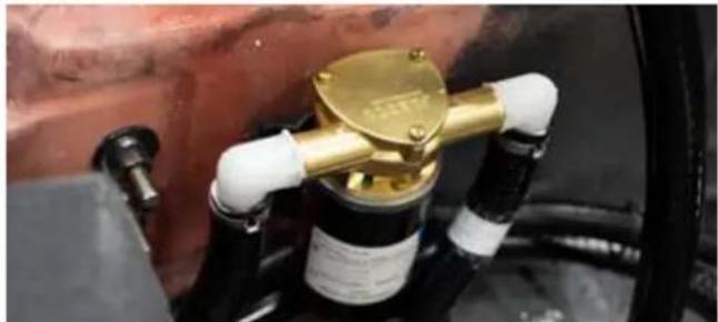
natural_image
Close-up of a mechanical device with a golden valve and white gloves, mounted on a black cylindrical component (no visible text or symbols)Step 4
Slide the plate back into place. No silicone is necessary. Due to the built-in gasket, tightening the screws should prevent leakage.
INSPECT THE COMPLETE FUEL SYSTEM FOR LEAKAGE AND CHANGE FUEL FILTER
Although the boat engine is similar to an automobile engine, the engine compartment differs substantially. The underside of an automobile engine compartment is totally open to the atmosphere. This allows complete air circulation and ventilation. A boat engine is housed in a closed compartment, the underside of which is the bottom (hull) of the boat.
The enclosed engine compartment limits the ventilation of gasoline and oil fumes. Because confined gasoline vapors mixed with a little air can form an explosive atmosphere, it is important to be especially vigilant in performing the following two (2) operations:
Step 1
Inspect the boat bilge area under the engine for the evidence of oil and gasoline—or any gasoline odor. This inspection should take place the first time the boat is started each day. Raise the engine cover and visually look at the bilge area under the engine.
Step 2
Run the bilge blower for at least four (4) minutes to ventilate the bilge area each time before starting the engine.

DANGER
Gasoline is explosive. If a gasoline odor is present or gasoline is visually observed in the bilge area during inspection, DO NOT START YOUR ENGINE! Remove the ignition key from the ignition switch and call an authorized MasterCraft dealer for service.
NOTE: If there is evidence of loose fuel fittings, deteriorated lines or other problems associated with the fuel system, call an authorized MasterCraft dealer. Fuel system service on later-model MasterCraft boats requires special service tools and special training. Due to the potential for serious consequences when errors occur in servicing the fuel system, MasterCraft strongly encourages all boat owners and operators to seek professional assistance from an authorized MasterCraft dealer's service department whenever any service or perceived problems occur within the fuel system.

CAUTION
All replaced fuel components must meet United States Coast Guard ("USCG") and American Boat & Yacht Council, Inc. ("ABYC") standards, and must be Underwriter's Laboratory ("UL")-approved. Inferior quality components pose a serious safety threat to
you and others, and the use of inferior components may result in serious injury or death. Resulting damage may void the warranty.
All MasterCraft models are equipped with a fuel fill cap such as shown in this section. These caps are hinged, and they snap open or closed to seal with an audible click. This is important for the system on these boats to operate correctly. Be sure to fully snap shut the cap after each fill.
As part of the Annual Maintenance, the fuel filter must be changed. Due to the pressurized fuel lines, this maintenance can be done only by authorized MasterCraft dealers.
Fire Extinguisher And Suppression Units
MasterCraft recommends that boat owners include a check of the fire suppression and extinguisher units during the annual maintenance to be sure that they are always ready for use. Some units may not require annual checks; refer to the signage and labeling on the individual units for further guidance.
Other Maintenance
Boat owners are required to perform routine regular maintenance as well as annual requirements, as outlined in the engine owner's manual. Some standard or optional equipment on boats may come with their own printed information that includes maintenance required to keep such components in excellent long-term operating condition. Always follow these instructions.

natural_image
Two people surfacing a jet ski boat on water, with splashes indicating speed and water flow (no text or symbols visible)STORAGE & WINTERIZATION
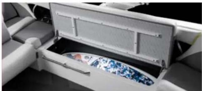
natural_image
Interior view of a modern office or cinema space with a large open storage unit and a circular display panel (no visible text or symbols)Storage or winter lay-up requires special preparation to prevent damage to the boat. Since winter storage is an annual event, it presents an excellent opportunity to perform the annual maintenance at this time, depending upon the amount of usage. Check with an authorized MasterCraft dealer's service department regarding the boat's needs to determine if this is the appropriate time for annual service.
Without proper preparation, storage for long periods of time (at any time of the year) may cause harm to various components of the boat and drive train. Also, if the boat has been stored in below-freezing temperatures with water inside the bilge or engine cooling system (including the heater, shower, ballast tanks, wash down tanks, coolers, bilge and ballast pumps, or any container or area in which water has been located), this condition may result in major damage from freezing, which would not be covered under the warranty.
Refer to the engine owner's manual for guidance regarding storage and winterization of the engine, transmission and components of the drive train.
The following procedures will help avoid most potential types of damage during storage for a period not to exceed five (5) months!
CAUTION
Because of the complexity of preparing a boat for proper winter storage, as well as the possibility of extreme damage to the drive train if a preparation error was made during winterization, MasterCraft recommends scheduling an appointment with an authorized MasterCraft dealer's service department to permit a technician to perform all winterization procedures.
GENERAL PREPARATION
Before starting you will need the following supplies:
• Sta-Bil ^® Gasoline Stabilizer
- Fuel filter
- Low tack tape
FUEL SYSTEM TREATMENT
This preparation needs to be done prior to removing water from the engine, if that will be part of the process.
Boats that are going to be stored for extended periods (more than two [2] weeks) or winterized should have attention for the fuel system. Even TOP TIER gasolines will experience some separation
of elements and settling during these periods. Of considerable concern is that water condensation will occur within the fuel system, and water is an enemy of good-starting and running engine fuel systems. Therefore, follow this procedure:
Step 1
The fuel tank should be ninety-to-ninety-five percent (90-95%) full of TOP TIER gasoline. This allows for minimal room in which air can oxygenate the fuel during diurnal cycles (daily periods of expansion/con-traction of gasoline vapors and air as a result of temperature changes). However, MasterCraft boats have EPA-dictated fuel systems, which means they cannot be overfilled. The boats are equipped with ullage (overflow) tanks or ullage space in the main tank. Equipped with several valves to prevent overflow, even in high heat conditions with 100 percent full fuel, our expansion tanks will expand by seven-to-nine percent (7-9%), as opposed to the five percent (5%) required by the EPA. As temperatures rise in the tank, the pressure also rises, pushing out gasoline vapor-and-air mixtures. When the temperature falls, pressure lowers and the system will seek to draw fresh air and water vapor (depending on the humidity level) into the tank. Fresh air is replaced with "light ends," which are low-boiling components that vaporize at ambient temperatures. Light ends are required during cold starts to vaporize the fuel. Since the daily diurnal cycles eliminate the light ends, a full tank helps to minimize the air volume entering the system.
Step 2
Add a biocide additive in the fuel tank to limit microbial growth in gasoline. Follow the directions provided by the additive's manufacturer.
Step 3
Add a fuel stabilizer, such as Sta-Bil ^® , preferably the Marine grade or Ethanol grade stabilizer, to the fuel tank. Follow the directions provided by the stabilizer's manufacturer.
Step 4
Run the engine for at least fifteen (15) minutes while in a body of water. This allows for the circulation of the additives throughout the fuel system.
During storage, the tank vents can be sealed. If the vent is sealed, the tank must NOT be completely filled. A ninety-to-ninety-five percent (90-95%) filled tank allows room for expansion, which will be required at certain times when temperatures increase. In addition to preventing water intrusion, sealing can preventing "gumming." The hydrocarbons in gasoline react with naturally occurring oxygen and create a by-product known as "gum." The substance, as the name infers, plugs up fuel filters and injectors. Sealing the tank helps reduce gumming by significantly limiting the amount of oxygen available for interaction with the hydrocarbons. If the tank vent is sealed for storage/winterization, it is imperative to ensure that
the vent is unsealed prior to the boat being placed back into service! Failure to do so will result in issues in trying to fill the gas tank in future fill-ups.
It is desirable to keep the fuel's temperature below 80 F. (26 C.) The gumming will increase as temperatures increase.
Note that fuel stabilizers work ONLY in fresh gasoline. Stabilizers will not cure oxygenated gasoline. Adding a stabilizer when the boat is being prepared for outings after storage will NOT clean the gumming that has occurred or remove water from the fuel tank or otherwise eliminate any problems that have occurred due to failure to properly prepare the fueling system for storage.
Engine manufacturers suggest using Federal or State of California reformulated gasoline whenever possible as it stores as well or better than conventional gasoline.
Even quality gasoline that has been properly prepared for storage should never be stored for a period to exceed one (1) year.
CAUTION
Fuel systems on all boats MUST be properly prepared for storage periods exceeding two (2) weeks, as outlined in this Owner's Manual. Failure to do so will void the warranty.
GENERAL POWER PACKAGE PREPARATION
Step 1
Lubricate the throttle and shift linkages and cables with multi-purpose grease.
Step 2
MasterCraft recommends that batteries be removed from the boat for winter storage. Batteries should be fully charged before being stored in a cool, dry location, protected from the elements and fully recharged before being reinstalled in the boat. Never store batteries close to heat, spark or flame-producing devices.
Step 3
Leave the engine box cover propped open about two inches (2") to ventilate the engine compartment.
OTHER WINTERIZATION PREPARATIONS
Step 1
Remove the bilge drain plug immediately after taking the boat out of the water. After a general bow-to-stern washing, raise the bow of the boat higher than the stern to allow as much water as possible to drain from the bilge, while performing other storage preparations.
Step 2
Thoroughly clean the hull, deck and interior of the boat as soon as it is removed from the water. Cleaning at this time is easier because any marine growth is still wet. Be sure to allow a few days of air drying to prevent mildew that results from trapped moisture. (See the Cleaning section of this Owners Manual.)
Step 3
Apply a coat of wax to the entire surface of the boat. We suggest MasterCraft Premium Marine Wax for excellent coverage.
Step 4
If the boat is equipped with a heater, shower or ballast bags/tanks, be sure to disconnect the hoses and drain any remaining water in the lines to avoid freezing. Even small amounts of water in any of these areas can cause significant damage upon freezing, and such damage is not covered under the warranty!
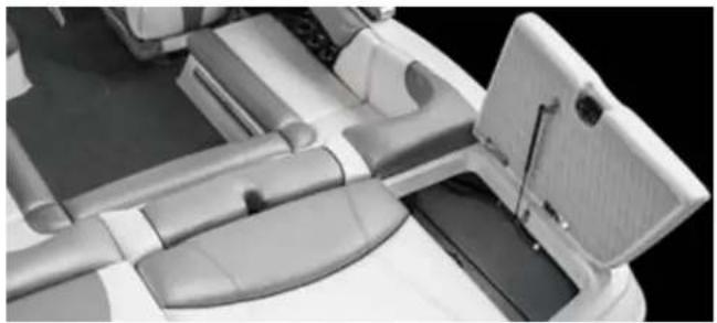
natural_image
Interior view of a car showing dashboard, seat, and camera module (no visible text or symbols)NOTE: Be sure that hoses will not become entangled in the engine belt when the engine turns over or the hose and/or the belt will be damaged.
Step 5
Use duct tape to seal the exhaust flaps to prevent dirt and nesting rodents from entering.
Step 6
On X26 boats equipped with heads, clean the tanks with a mild cleaner or warm soapy water that will not harm the finish. Avoid all petroleum-based household cleaners. Store the head dry and clean. Failure to do so may cause unnecessary odors and damage to the tanks, and this is not covered under warranty. If using anti-freeze in the head, drain the potable water tank and add freshwater anti-freeze to the potable water tank. Flush the antifreeze and water mixture through the head and into the waste holding tank. Then
empty the holding tank. Never use automotive-type anti-freeze in this freshwater system.
Step 7
If the tower will be lowered during storage, be certain that the tower does not rest on the boat upholstery or on any support that rests on the upholstery. The tower or support(s) may leave a permanent imprint on the upholstery. This is not covered under warranty.
Step 8
Cover the boat with a boat cover or tarp.
NOTE: If the boat is to be stored outside and subject to accumulations of snow, water and ice, a support should be made for the boat cover so that it will not sag, rip or tear, thereby allowing water to enter the boat. Two-inch diameter PVC plumbing pipe is ideal for this purpose. It is readily available at local hardware stores, and it is easy to work with. Also, its rounded shape will prevent damage to the canvas.
BALLAST SYSTEM PREPARATIONS
Step 1
Attach a hose to the starboard side ballast hose that comes out of the deck at the rear seat.
Step 2
Place the other end into a gallon of non-toxic, RV-type antifreeze.
Step 3
Turn the pump on to empty and pump anti-freeze into the system until antifreeze comes out of the thru-hull on the side.
Step 4
Turn the pump on to fill and pump antifreeze back into the jug.
REACTIVATING THE BOAT AFTER STORAGE
Step 1
Remove the duct tape from the exhaust flaps.
Step 2
Fully charge the battery and install it in the boat, following all safety precautions associated with changing batteries.
IMPORTANT NOTE: Often, batteries that have been stored over winter will require recharging. If the battery is charged by utilizing a battery charger, use only a three-stage or more battery charger. It is important that the operator never turn a battery charger immediately to "start," as the sudden jolt of voltage may cause damage to the electrical system, particularly control modules for ballast system. Regardless of whether it is during the reactivation process or at any time, care should also be used in charging the battery.
Step 3
Follow all instructions for reactivating the drive train as detailed in the engine owner's manual.
NOTE: Due to the complex nature of the reactivation process, MasterCraft recommends having an authorized MasterCraft dealer perform this function.
Step 4
Ensure that all drain plugs throughout the boat and drive train have been reinstalled to avoid unwanted intrusion of water.
Step 5
If applicable, reconnect the hoses to your heater or shower.
Step 6
Check the engine compartment and bilge for signs of nesting animals. Clean as necessary.
Step 7
Check the entire engine system for fluid, oil and coolant levels. Add as necessary.
Step 8
Check the entire engine for cracks or leaks caused by freeze damage.
Step 9
Check all hose clamps for tightness. Install the bilge drain plug and the rear drain plug in boats equipped with certain types of ballast systems.
Step 10
Grease the propeller shaft taper and install the propeller.
Step 11
Fully recharge and reinstall the battery or batteries.
Step 12
Perform the daily maintenance as noted previously in this Owner's Manual. If it was not done prior to storage, perform the annual maintenance as well.
Step 13
If the boat is equipped with the optional fresh water cooling system and was drained for storage, fill the system with fresh coolant solution per instructions.
Step 14
Check the alignment between the output flange on the transmission and the propeller shaft flange. If the maximum feeler gauge that can clip between the flange faces at any point is 0.003", the unit is properly aligned. If a thicker gauge can be inserted at any point, the engine must be readjusted until proper alignment is obtained. This should be performed by an authorized MasterCraft dealer's service department.
Step 15
For all models, with the boat in the water, cycle the key ON and then OFF two (2) or three (3) times, allowing ten (10) seconds between key cycles, before cranking the engine. This allows the fuel pump to prime the fuel lines; then start the engine. In the event the engine does not respond, allow a two-minute cool-down period for every
thirty (30) seconds of cranking. When the engine fires, keep a close watch over the gauge readings and check for leakage and abnormal noises. Keep speeds low for the first fifteen (15) minutes to allow the engine to reach normal operating temperatures.
PROPELLER MAINTENANCE
Propeller damage is caused by striking solid objects. If the propeller is not rotating at the time it strikes a solid object, the damage is usually confined to just one blade and may be difficult to see. If the propeller is rotating when it strikes an object, usually the resulting damage can easily be seen on all blades.
CHECKING/REPAIRING PROPELLERS
Step 1
Ensure the engine is OFF and the emergency safety stop switch is disconnected.
Step 2
Clamp a small rule scale to the shaft strut, parallel to the shaft so that the end of the scale is 3/32-inches from the leading edge of a propeller blade.
Step 3
Rotate the propeller slowly. There should be no more than 3/32-inch variance between the blades. If the propeller is damaged, see an authorized MasterCraft dealer.
CHANGING PROPELLERS
Step 1
Ensure the engine is OFF and the engine safety starting switch is disconnected.
Step 2
Remove and discard the cotter pin.
Step 3
Remove the propeller nut.
Step 4
Tap the center hub of the propeller with a rubber mallet to release the propeller. Inspect the shaft and propeller splines for damage.
Step 5
Thoroughly clean and apply a light coat of waterproof marine multi-purpose grease to the splined area of the shaft and propeller.
Step 6
Align the splines and carefully install the propeller onto the shaft.
DO NOT FORCE THE PROPELLER INTO PLACE.
Step 7
Install the propeller nut and torque to 50-ft-lbs.
Step 8
Install a new cotter pin and bend the ends around the shaft to lock the propeller on the shaft.
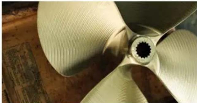
natural_image
Close-up of a four-blade propeller with visible blades and central hub, placed on wooden surface (no text or symbols)
natural_image
Speedboat with 'MasterCraft X' branding speeding on a lake surrounded by dense green trees (no text or symbols on the boat itself)TRAILERS
$$ \frac{1}{2} = \frac{1}{2}\left( \frac{\ln x}{2} - \frac{\ln y}{2} \right) + \frac{1}{2}\left( \frac{\ln z}{2} - \frac{\ln y}{2} \right) $$
Please take a few minutes to read this section of the Owner's Manual completely before using your MasterCraft trailer for the first time. It provides substantial information about the trailer. If you still have questions after reviewing this information, be sure to contact an authorized MasterCraft dealer. It is important that any and all trailer operators possess as much knowledge as possible.
NOTE: The information given in this Owner's Manual may not be applicable to international laws or rules of the road. If you have any questions, please contact your local authorities.
Trailer Maintenance Quick Tips
natural_image
Close-up of a vehicle's wheel assembly with yellow components and a black brake caliper (no visible text or symbols)Chips In The Paint
Especially on the axles and frame of the trailer, paint chipping generally results when these surfaces are subjected to repeated or significant impacts by various objects while in transit. Usually, these are gravel, stones, asphalt chips or other debris on roadways, which are thrown up by the rear tires of the tow vehicle. Over time, rust may develop where paint has been chipped away, and such damage is not covered by the Limited Warranty for the trailer. To avoid chipping the paint on the trailer and to preserve its condition, consider attaching mud flaps behind the tow vehicle's rear tires. Exceptional care should be taken to travel as slowly as practical when traveling on gravel or other loose surfaces.
Lubrication
To ensure proper operation of the trailer jack, wipe it down and lubricate it on a regular basis.
Salt Water Effects
If the trailer is backed into salt water, you must completely and thoroughly wash the trailer in fresh water to retard rusting. Salt water is very corrosive, even on galvanized trailers, and can corrode the braking system as well. Exposure to salt water can also cause brake pads to stick and malfunction.
Regular Cleaning
The trailer will look better and last longer if it is rinsed off with fresh water several times a year. If the boat is run in brackish or salt water, the trailer should be rinsed thoroughly after every trip because of residual effects of the brackish or salt water. An annual washing with a mild detergent and waxing with an auto wax will also help to keep the trailer bright and clean.
Braking System
Check the braking system at the beginning of the boating season and again at the conclusion, along with the wheel bearings. If there is anything that appears to be worn or leaking, take the trailer to an authorized MasterCraft dealer for a check and possible repair.
Tow Vehicle Approach
Tow vehicles must always approach the trailer slowly prior to being hitched to the trailer. This allows the operator to retain greater control. Hard impact with the trailer or improper alignment on the trailer can result in damage to the tow vehicle, boat and/or the trailer, and any such damage is not covered under warranty.
Seven-Wire Connector
The tow vehicle must have a seven-wire connector in order for disc brakes and the trailer lights to function properly. It is important to properly connect the seven-wire connector on the trailer to the seven-wire connector on the tow vehicle.
natural_image
Close-up of a black mechanical component with a coiled spring attached, no visible text or symbolsLoad Limit
The correct method for determining the load limit is to:
- Locate the statement, "the weight of cargo should never exceed _kg or _lbs," On the trailer tongue. (The number shown equals the total weight capacity for the boat and all contents that can be safely loaded and towed on the trailer.)
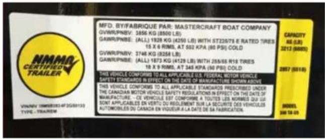
text_image
MFD. BY/FABRIQUE PAR: MASTERCRAFT BOAT COMPANY GVWR/PNBV: 3556 KG (8500 LB) GAWR/PNBE: (ALL) 1928 KG (4250 LB) WITH ST22678 E RATED TIRES 15 X 6 RIMS, AT 502 KPA (80 PSI) COLD GVWR/PNBV: 3746 KG (8256 LB) GAWR/PNBE: (ALL) 1873 KG (4129 LB) WITH 265/66 R18 TIRES 18 X 9 RIMS, AT 345 KPA (60 PSI) COLD THIS VEHICLE CONFORMD TO ALL APPLICABLE U.S. FEDERAL MOTOR VEHICLE SAFETY STANDARDS IN EFFECT ON THE DATE OF MANUFACTURE SHOWN ABOVE THIS VEHICLE CONFORMS TO ALL APPLICABLE STANDARDS PRESCRIBED UNDER THE CANADIAN MOTOR VEHICLE SAFETY REGULATIONS IN EFFECT ON THE DATE OF MANUFACTURE - CE VEHICLES ESP COMPOME A TUTES LES NORMES QUI LS SONT APPLICABLES EN VERTU DU RÉGLEMENT SUR LA SECURITE DES VEHICLES AUTOMOBILES DU CANADA EN VIGUEUR A LA DATE DE SA FABRICATION CAPACITY NS (LB) 3212 (5000s) 2887 (5018) MODEL. 348 TO 09- Determine the combined weight of the boat and all contents of the boat being loaded onto the trailer. The boat's weight is listed in the guide to individual models section of this owner's manual. (The total weight of the boat and contents may not safely exceed the available cargo load capacity listed on the trailer tongue.)
- Walk around inspection: the majority of potential roadside issues can be eliminated by a walk-around visual inspection of the trailer. This should be done after hitching the trailer to the tow vehicle, and again at each fuel or rest stop.
Make A Quick Visual Check Of:
- Coupler
- Safety cables
• Emergency brake cable - Wiring connector
- Tie-downs
- Tires
Look For:
- Any obvious fluid leaks
• Unusually hot brakes or hubs
• Damage caused by road hazards - Low tire pressure
Make a point to pay particular attention to the right (starboard) side of the trailer, as this is typically where most road hazard damage occurs.
These are some brief tips for maneuvering with a trailer attached to a tow vehicle:
Backing Up
When backing up, place your hand at the bottom of the steering wheel. To turn left, move your hand left (rotate the wheel clockwise). To turn right, move your hand right (rotate the wheel counterclockwise). Back up slowly. Because mirrors cannot provide all of the visibility you may need when backing up, have someone outside at the rear of the trailer to guide you while backing up, whenever possible. Use slight movements of the steering wheel to adjust direction. Exaggerated movements will cause greater movement of the trailer. If you have difficulty, pull forward and realign the tow vehicle and trailer and start over.
Parking
When parking, try to avoid parking on steep grades. If possible, have someone outside to guide you as you park. Once stopped, but before shifting into park, have someone place blocks on the downhill side of the trailer wheels. Apply the parking brake, shift into park, and then remove your foot from the brake pedal. Following this parking sequence is important to be sure your vehicle does not become locked in park because of extra load on the transmission. For manual transmissions, apply the parking brake and then turn the vehicle off in either first gear when parked uphill, or reverse gear, when parked downhill.
Uncoupling
When uncoupling the trailer, place blocks at the front and rear of the trailer tires to ensure that the trailer does not roll away when the coupling is released.
Unbalanced Load
An unbalanced load may cause the tongue to suddenly rotate upward; therefore, before uncoupling, place jack stands under the rear of the trailer.
Difficult Towing
If a trailer seems hard to tow or sways to one side, a brake rotor may not be rotating freely. If this appears to be the problem, immediately contact your authorized MasterCraft dealer for assistance. Ignoring this symptom could result in brake failure.
Check Trailer Jack and Lug Wrench
The trailer jack and lug wrench that came with the tow vehicle may also work on the trailer, but don't count on it! Check to make sure.
Road Trip Kit
Make up a special road trip kit and carry it with you on all trips. The kit should include a spare wheel and tire, lug wrench, wheel chocks, bearing grease, spare strap for tie-downs and winch, extra lights, wheel bearings and road flares.
Insurance
Some insurance policies do not provide coverage when towing a trailer. Check the policy or call the insurance agent to be certain that you have appropriate insurance coverage in place.
Introduction
With the purchase of a new MasterCraft trailer, custom-built to integrate with a MasterCraft boat, value has been added to the boating experience. Access to thousands of recreational waterways is now available.
MasterCraft produces trailers to accompany its various models of superior boats. These trailers have been specifically designed for many years of attractive and trouble-free service. Now, it is up to the owner and/or operator to give the trailer proper care and maintenance to be sure it will continue to perform safely and satisfactorily for years to come.
The purpose of this section of the Owner's Manual is to provide the information that owners and operators need to fulfill that goal. Please read and follow the warnings and instructions carefully. Also, because all trailers are not exactly alike, be sure to read and comply with any warnings and additional information supplied by Master-Craft and its parts suppliers within the owner packet. It's the best way to obtain peak performance.

WARNING
Before towing this trailer, be sure to read and understand this Owner's Manual.
A Proper Match
The key to carefree boat trailering is the proper match of boat to trailer. This proper match is only one reason why the MasterCraft engineering staff has designed the trailer to carry the full weight of the boat, engine and a reasonable amount of gear. It also provides the proper support for the boat hull during storage.

The total weight of the boat, engine, fuel, water and gear must not exceed the trailer's maximum load-carrying capacity. Overloading can cause instability and loss of control while towing, which may result in death, serious injury or property damage.
Load-Carrying Capacity
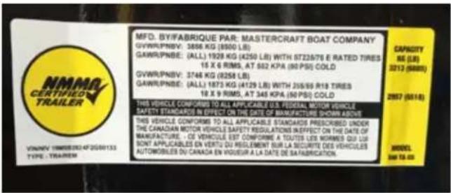
text_image
MFD. BY/FABRIQUE PAR: MASTERCRAFT BOAT COMPANY GVWR.PNBY: 3856 KG (8500 LB) GAWR.PNBE: (ALL) 1928 KG (4250 LB) WITH 6722676 E RATED TIRES 16 X 6 RIMS, AT 502 KPA (90 PSI) COLD GVWR.PNBY: 3746 KG (8258 LB) GAWR.PNBE: (ALL) 1873 KG (4129 LB) WITH 26599 R18 TIRES 18 X 9 RIMS, AT 346 KPA (90 PSI) COLD THIS VEHICLE CONFORMS TO ALL APPLICABLE U.S. FEDERAL MOTOR VEHICLE SAFETY STANDARDS IN EFFECT ON THE DATE OF MANUFACTURE SHOWN ABOVE THIS VEHICLE CONFORMS TO ALL APPLICABLE STANDARDS PRESCRIBED UNDER THE CANADIAN MOTOR VEHICLE SAFETY REGULATIONS INPECT ON THE DATE OF MANUFACTURE - CE VEHICLE EST CONFORME A TOUTES LES NORMES QIX LTR SONT APPLICABLES EN VERTU DU RÉGLEMENT SUR LA SECURITE DES VEHICLES AUTOMOBILES DU CANADA EN VIGUEUR A LA DATE DE SATABRICATION. CAPACITY SE (LB) 3212 (9000) 2957 (9018) MODEL 340 TO 00Check the certification label attached to the front left side of the trailer. This is very important as it shows the maximum load-carrying capacity of the trailer. It will also show the Gross Vehicle Weight Rating (GVWR). Be sure that the total weight of the boat, engine, gear and trailer does not exceed the GVWR.
NOTE: The gross Vehicle Weight Rating ("GVWR") is the estimated total weight of a road vehicle that is loaded to capacity, including the weight of the vehicle itself. Therefore, the maximum load-carrying capacity of the trailer is the GVWR less the weight of the empty trailer.
Be especially careful to avoid overloading the trailer by putting heavy baggage, camping gear, etc. inside the boat.
Do not tow the boat with a water-filled bladder or with water in the ballast tanks. Failure to empty the contents of bladders or ballast tanks will cause the tongue weight percentage to be incorrect. Towing with water-filled bladder(s) may not only cause the total weight limits for the trailer to be exceeded, but may also result in the improper distribution of the weight on the trailer, thereby making towing difficult and/or causing instability when towing, which can be very dangerous to the driver, any passengers and to other motorists.

WARNING
NEVER tow with water in ballast tanks or bags. Failure to empty ballast tanks, bladders or bags on the boat prior to towing can result in improper weight distribution, which can cause towing instability. This could cause the driver to lose control of the tow rig, resulting in death or serious injury to the driver, any passengers and/or to other motorists, or property damage.
Do not tow the boat with wakeboards, skis or other gear left on the board tower racks. Doing so may void the warranty and cause damage to the boat or to vehicles following behind, as boards and/or racks may become disengaged.

WARNING
Do not tow with any gear in the tower racks, even if the gear appears to be secure. The racks are not designed to withstand air pressure from highway speeds. Gear may become dislodged, potentially causing damage to the boat or following vehicles.

CAUTION
Loose objects may damage the boat and/or trailer. Such damage is not covered by the warranty.
Weight Distribution

WARNING
Improper weight distribution within the boat can cause instability and loss of control while towing, which may result in death, serious injury or property damage.
Improper weight distribution can cause a boat trailer to fishtail (sway from side to side) as it moves down the highway, putting excessive strains on both the trailer and the tow vehicle, which increases gas consumption and may potentially cause an accident. The most effective way to guard against fishtailing is to make sure the weight load on the trailer is properly distributed.
It is extremely important that a minimum of five percent (5%) and a maximum of ten percent (10%) of the total weight on the trailer is on the trailer coupling ball when the tongue is parallel to the ground. A bathroom scale can be used for this determination. For example, if the gross weight of the trailer, boat and gear is 3,000 pounds, the weight on the tongue should not be more than 300 pounds, but not less than 150.
Check the tow vehicle owner's manual prior to first time use.
The importance of sufficient weight load on the trailer tongue (creating downward force on the hitch ball) cannot be over-stated.
The Trailer Hitch
There are two basic types of trailer hitches: a weight-carrying hitch and a weight-distribution hitch. A weight-carrying hitch is recommended for use with a MasterCraft boat and trailer. However, weight-distributing (equalizing) hitches may be used.
If using a weight-distributing hitch, the chain must be vertical (straight up and down) under the pulling load where the actuator is extended. Excessive tongue weight beyond the actuator rating must be avoided as it will reduce the brake performance and could damage the actuator. Always follow the hitch manufacturer's instructions. Before deciding upon which type of hitch to use, also consult the tow vehicle manufacturer for recommendations from the tow vehicle's perspective.
Be sure that the total weight of the trailer-boat rig does not exceed the hitch's load capacity. The maximum permissible weight for the hitch should be stamped on the hitch. The hitch should also provide a place for attaching the trailer's safety cables—two rings or holes on either side of the hitch ball. Also, be sure the hitch ball is the correct size to match the coupler on the trailer. The correct ball diameter is marked on the trailer coupler.
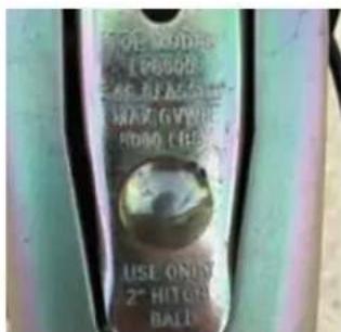
text_image
OF BODERS (10000) 45" BLACK RAW GYWHIE ROBO GREEN USE ONLY 2" HITCH BALL
WARNING
Failure to use a two-inch (2") hitch ball and mount rated to 8500-lbs. or higher, where required, may result in failure of the hitch on the tow vehicle and a loss of control of the trailer while towing, which may cause serious injury or death.
A truck or van using a step bumper as the hitch platform will need to have safety cable attachments such as eye-bolts, as well as a hitch ball, which has been installed according to the Society of Automotive Engineers (SAE) J684 Standard. Installing a light or heavy-duty hitch can be a major undertaking. The hitch and its installation must meet the SAE J684 Standard. It is recommended that the job be done by a professional. An authorized MasterCraft dealer can offer advice.
To ensure that the boat is riding properly on the trailer supports, the trailer should be in a level position when hitched to the tow vehicle. With the trailer hooked up to the tow vehicle and the jack stowed, measure from the bottom of the frame (behind the swing tongue) to the ground. This measurement should be 20.5"-21.5" More importantly, failure to adjust to this height may prematurely activate the surge brakes.
This can be corrected in a number of different ways. For example, air pressure adjustable shock absorbers may be installed on the tow vehicle, or you can switch from a weight-carrying to a weight-distributing hitch. Consult with the tow vehicle's dealer or manufacturer.

WARNING
If the total weight on the loaded trailer exceeds the load capacity of the hitch on the tow vehicle, then the trailer may break free, which may result in serious injury or death and/or property damage.
Never Attach The Trailer To Any Device Between The Trailer And The Tow Vehicle!
The photo shows an example of an improper device attached between a trailer and tow vehicle that may create a dangerous condition for towing a boat. Devices like the one shown in the photo may be built or marketed with the idea of improving stability in towing, but instead, devices of this nature may create a very unstable
condition in which control of the trailer may be lost during towing. The MasterCraft trailer was designed and built to be attached directly to the tow vehicle, and the trailer should only be attached in that manner. This is especially critical in maintaining the proper weight balance, which is described in more detail in this section of the Owner's Manual.
Safety Cables
The safety cables on a MasterCraft trailer provide added security so that the trailer will not become detached from the tow vehicle when underway. These cables conform to the Society of Automotive Engineers (SAE) J684 standard for trailer coupling and hitches automotive type. If it ever becomes necessary to replace these cables, ensure that the replacement cables meet this standard.

WARNING
Failure to properly attach the safety cables and brake actuator break-away cable between the trailer and the tow vehicle may result in a runaway trailer if the trailer coupler becomes detached from the hitch. This may cause serious injury or death and/or property damage.

WARNING
The strength rating of EACH safety cable must be equal to or exceed the trailer's GVWR (Gross Vehicle Weight Rating).

WARNING
Trailer sway control devices that restrict the operation of the actuator MUST NOT be used. These devices can limit the effectiveness of the trailer brakes work.
Before each trip, ensure that the safety cables are correctly attached between the tow vehicle and the trailer. Secure the break-away cable to the bumper or frame of the tow vehicle as close to center as possible but do not attach to the safety cables.
natural_image
Close-up of a metal hook with a black cable and metal ring attached, on a plain surface (no text or symbols visible)As noted above, the trailer hitch should provide a place for attaching safety cables, through holes or rings on both sides of the hitch ball. It is strongly recommended, and most states require, that the cables be crossed under the trailer tongue (e.g., the cables on the left side of the trailer tongue should be attached to the hole or ring on the right side of the hitch ball, and the right side cable should be
attached to the hole or ring on the left side of the hitch ball). This will slow the process of the dropping of the trailer tongue if the trailer coupler separates from the hitch ball. The cables should be rigged as tightly as possible, with just enough slack to permit tight turns. If for any reason it becomes necessary to replace a safety cable, do not substitute with any part other than a genuine MasterCraft cable.
Breakaway Cable
Secure the breakaway cable to the bumper or frame of the tow vehicle as close to the center as possible, but do not attach it to the safety chains. The cable MUST hang clear of the trailer tongue and be long enough to permit sharp turns without pulling the cable and will not be applied unless the safety chains fail. The intent of the breakaway cable is to apply the brakes if the safety chains fail.
Do not loop an S-hook over the breakaway cable to attach it.

WARNING
Never tow a trailer without the breakaway cable secured to the tow vehicle.
To retract the breakaway cable, slide the coupler fully forward and push up on the push rod release bracket located on the underside and behind the hitch ball socket.
Checking And Resetting The Breakaway Cable
natural_image
Close-up of a metal hook attached to a concrete floor, with a hanging weight and a small label nearby (no visible text or symbols)To retract or release the breakaway cable, remove the plastic cap on top of the actuator. Verify the E-stop (breakaway cable) is "set", with the cable bracket toward the rear of the opening. To release, press on the forward E-stop release bracket (front of opening) with your finger or a screwdriver until the E-stop cable bracket snaps back into the forward, disengaged position. A screwdriver may be needed to assist in prying the cable bracket forward.
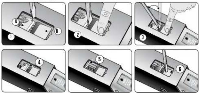

CAUTION
The breakaway system must be reset anytime the cable has been pulled.
(See the lockout information elsewhere in this section of the Owner's Manual.)
Trailer Winch Assembly

WARNING
Maintain a firm grip on the winch handle at all times. Never release the handle when the ratchet level is in the unlocked position with a load on the winch because the handle will spin forcefully under these conditions, which may cause serious injury. Also, if the winch is released and begins to spin forcefully, do NOT attempt to halt the spin.
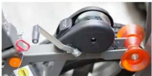
natural_image
Close-up of a mechanical assembly with orange rollers and a black component, no visible text or symbolsPrior to each use of the winch, check for the proper ratchet operation. Do not use the winch if it is damaged. Seek immediate repairs. Never use the winch handle as a handle for pulling or maneuvering the entire trailer or other equipment.
Never pull on the winch handle against a locked ratchet. Never exceed the rated capacity of the winch. Excessive loads may cause premature failure. Never apply a load on the winch with the strap fully extended. Keep at least two full turns of the strap that is on the reel. Inspect the condition of the winch strap.
Using a damaged or worn winch strap may result in serious injury or damage. Check the winch straps frequently. The strength in these can deteriorate from exposure to weather, ozone and ultraviolet light (direct sunlight). If a strap becomes frayed or worn, replace it immediately with a new one.
A heavy grease should be applied to the gears to provide a free-running drive and to minimize the effort you have to expend to crank the boat onto the trailer.
The winch is intended solely as an aid to loading the boat on the trailer. It is not recommended to use the winch as the sole method for loading the boat onto the trailer. However, it is a satisfactory assistant in the event of engine power loss. Also, it is not intended or adequate to be the sole means of holding the boat in place while loading the boat onto the trailer. Proper tie-downs fore and aft must be used.
Swing Tongue
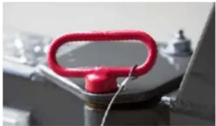
natural_image
Close-up of a red handle knob on a metallic stand, with no visible text or symbolsEnsure the swing tongue is folded fully forward, the pivot pin is installed, and the keeper pin is installed in the bottom of the pivot pin before towing. When folding the swing tongue open or forward to the fully closed position, be sure that the brake hose is not kinked or pinched in any way. A pinched or kinked brake hose will cause the brakes to drag and overheat.
NOTE: Because all pins, fasteners and other components are specially designed, high-strength components, any component replacement or adjustment of the swing tongue should be performed by your authorized MasterCraft dealer.
How To Attach The Trailer
To connect the trailer to the tow vehicle, open the coupler mechanism (instructions below). When necessary, raise the trailer jack. Slowly back up the tow vehicle until the hitch ball is under the coupler. This is easier to perform with another person standing beside the trailer and guiding the driver.

WARNING
Do not move the trailer to the tow vehicle. When the trailer is moved without a tow vehicle, the brakes do not work.
If the latch accidentally opens, the coupler could detach from the hitch ball. The hitch pin should fit easily into the hole. If it does not, the coupler latch is not completely closed. Every time the coupler is attached to the hitch ball, be sure the coupler completely covers the hitch ball and the lift handle will not open. If the hitch pin is damaged or lost, contact an authorized MasterCraft dealer to purchase a replacement pin.

WARNING
You must install either the hitch pin that is supplied or a padlock (1/4" or 5/16" shank) into the hitch pin hole before towing to prevent the coupler latch from accidentally opening.
To Open The Coupler
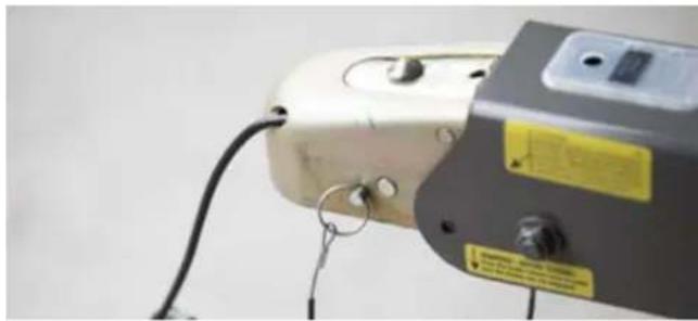
natural_image
Close-up of a white industrial machine with attached black cable and yellow warning labels (no readable text)Remove the hitch pin from the hole in the side of the coupler. Slide the lock/latch rearward which should allow the latch to spring upward. The coupler should unlatch easily. If not, the ball may be over-sized or egg-shaped, foreign matter could be lodged in the coupler ball socket, or the coupler is pushing on the hitch ball. Check to make sure the wheel on the tongue jack is raised or that the rig is not parked downhill. Correct these conditions, and then try to open the handle. Also, if the tongue jack is forcing the front of the trailer up or the trailer is pushing against the tow vehicle, it can also result in failure of the coupler to open properly.
To Close The Coupler
Place the coupler over the ball, lower the coupler and close the latch and slide the lock forward.
An audible "click" will be heard. The latch should close with finger pressure. If the latch will not close freely, the ball is not fully inserted into the socket, it is over-sized or egg-shaped, or the latching mechanism is damaged. DO NOT FORCE THE HANDLE. If necessary, replace the ball with a quality unit that meets SAE specifications.
Insert the hitch pin into the hole on the side of the coupler. The hitch pin will not go in the coupler if the hitch ball is not seated properly.

WARNING
DO NOT tow the trailer with the handle open or if the latch handle will not remain closed. Check to see that the coupler is locked. If the latch is damaged, contact an authorized MasterCraft dealer for assistance.
Lights

WARNING
Before each use make certain that all trailer lights are in proper working order to reduce the risk of serious injury, death and/or property damage.
The MasterCraft trailer harness was specifically designed to mate with O.E.M. automotive equipment. This harness is designed to disengage the trailer brakes with the use of the tow vehicle's O.E.M. harness.
NOTE: See an authorized MasterCraft dealer if the tow vehicle does not have the correct trailer harness.
The runway lights are brighter when the trailer is submerged. A sensor notifies the system when the trailer ramp is under water, and the lights will be at their maximum luminance. When the trailer is removed from the water, the lights will automatically dim. There is no consumer control for the system.
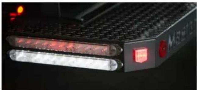
natural_image
Close-up of a black electronic device with LED lights and a red button, no visible text or symbols.Keep Trailer Lighting System In Good Working Order:
Be sure the white ground wire is properly connected to the master cylinder. Replace any parts that are damaged or worn.
A small amount of waterproof grease on the plug contacts and light bulb bases will help prevent rust and corrosion.
Before every trip, check for burned out or broken bulbs, cracked or broken light lenses, etc.
Hubs, Wheel Bearings, Axles And Lubrication

natural_image
Close-up of a car wheel rim with five black plastic blades and a central hub, mounted on a silver alloy wheel (no text or symbols visible)Trailers equipped with Tie Down Engineering actuators are also equipped with Vortex hubs and spindles. The hubs are pre-greased and assembled at the factory. As a result, they should not require any additional adjustments. The Vortex hub uses tapered roller bearings adjusted to a maximum .006 end play. The twelve-sided castle nut easily maintains this maximum .006 end play. The configuration requires a minimal amount of end play that is factored in at the time of assembly.
The rear seal rides on a stainless steel wear sleeve. This provides longer life for the seal as the surface does not corrode. Corroded or rusted seal surfaces act like sandpaper on the seal, causing premature seal failure, which is why every reasonable attempt has been made to avoid that.
Vortex lubrication makes changing or adding grease easy because the hub does not need to be removed. Most axles have a threaded grease cap, and it is easy to remove and replace.
Vortex requires Lucas Oil Marine grease, a premium lithium-based complex grease that is fortified with rust and oxidation inhibitors, and high-pressure additives that provides a high degree of moisture resistance and wash-out properties.

CAUTION
Use only Lucas Oil Marine Grease when adding or replacing grease in the Vortex hub. Using any other grease will void the warranty.
Adding Grease Or Removing Hubs
The Vortex hub/spindle is designed to be a no-maintenance hub for six (6) years. Remove the Vortex grease cap, unscrewing threaded caps in a counterclockwise rotation. On the press-in style caps, simply remove the rubber plug in the center to grease the bearings, or knock gently with a hammer, preferably a rubber mallet, if removing the entire hub, gently with a hammer, preferably a rubber mallet.
- Use a standard grease gun loaded with Lucas Oil Marine Grease to pump the grease into the zerk fitting located on the end of the spindle.
-
Pump the grease into the zerk fitting while slowly rotating the wheel. Grease will flow out of the hub around the front bearing.
-
When the grease appears to be the new clean grease, remove the grease gun.
- Replace the Vortex grease cap. With the threaded cap, turn in a clockwise rotation until the o-ring on the cap is in contact with the hub surface. Turn an additional one-quarter (1/4) turn to seal the Vortex cap to the hub. (Similar to installing an oil filter in an automobile.) On the press-in style cap, tap it on until fully seated. Be careful to avoid damaging the cap while re-installing.
If the bearings need to be adjusted or replaced, the work should be done only by an authorized MasterCraft dealer. Failure to contact MasterCraft for preapproval during the warranty period will void the warranty.
The wheel bearings have been precisely torque-set at the factory. To assure the bearings are in good working order, check the bearing adjustment at least once a year by following this procedure: Jack up one side of the trailer. (Be certain to use jack stands and use chocks on each of the trailer wheels to keep the trailer from moving during the inspection.) Grip the edge of the tire and see if it can be rocked or moved. If the outer edge of the tire moves more than a small amount, the bearings may need to be readjusted.
A slight amount of oil seepage at the rear seal is normal and necessary to lubricate the wiper lip of the seal for long life and sealing contaminants out. If excessive leakage is occurring, however, contact an authorized MasterCraft Dealer for assistance.
Wheels
Because they are often exposed to water, trailer wheels and tires require more attention than the wheels on a family vehicle. The three major items to check are lug nuts, lubrication and tire pressure.

WARNING
Maintain the proper torque on the lug nuts attached to the wheel bolts. Failure to do so may result in serious injury or death and/or property damage. An authorized MasterCraft dealer can provide the proper torque specifications (measured in foot-pounds).

WARNING
Keep the wheel bearings lubricated. Inspect the wheel bearings for proper lubrication before each use. Failure to do so may cause wheel failure and possible wheel loss, which may result in serious injury or death and/or property damage.
Aluminum wheels also require attention to routine maintenance, particularly in keeping them clean. Failure to do so may result in damage that is not covered by warranty.
The trailer and wheels should be washed weekly during boating season, and after every use if the trailer has been submerged in salt or brackish water. Use a soft brush, mild detergent and/or mild degreaser. A quality spray-on wheel cleaner may also be used.
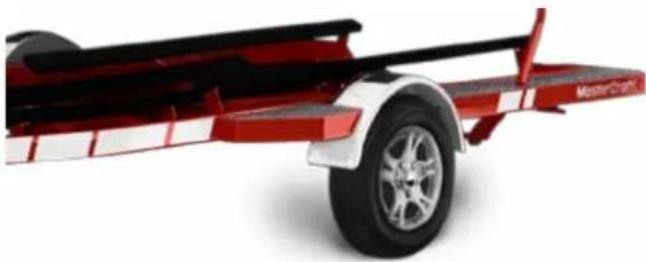
natural_image
Red and white striped cargo vehicle with a black frame and tire, no visible text or symbolsEnsure that any product used is specifically indicated for use on aluminum. (Many cleaners are too harsh and will result in pitting or other damage to the wheel surface.) Many car washes use strong chemicals and should be avoided when that is the case.
Removing road film, contaminants and brake dust (all of which retain moisture) is critical to ensuring that the wheels will retain their luster and quality finish for a long period of time. Any exposure to a harsh winter climate, particularly road salt and/or chemicals, or submersion in salt water at any time, requires immediate cleaning.
NEVER CLEAN WHEELS THAT ARE HOT.
Allow wheels to cool or cool them with running water. If the wheels are too hot, significant damage can occur to the wheels.

CAUTION
Wheels must always be cool or cold to the touch prior to cleaning. Failure to allow wheels to cool sufficiently can result in damage that is not covered under warranty.
It is also important to seal the wheels with a sealant that reduces static and resists brake dust. Check at an automotive supply store for an appropriate sealant.
Lug Nuts or Wheel Bolts
Loose wheel mounting nuts (lug nuts) can cause more than just an annoying wheel wobble—it's possible to lose a wheel. Before each trip check for loose or missing lug nuts/wheel bolts.

WARNING
Ensure that all lug nuts are secure prior to every time the trailer is towed. Failure to do so can ultimately cause a wheel to disengage from the hub. This can cause damage to the trailer that may not be covered under warranty, and serious injury or even death to the driver, any passengers and/or other motorists.
When tightening the lug nuts, use the correctly sized wrench. The wrong size can round off the lug nuts and render them useless. If you lose a lug nut, replace it promptly. The correct size varies with
different models, so verify the proper size with an authorized MasterDraft dealer.
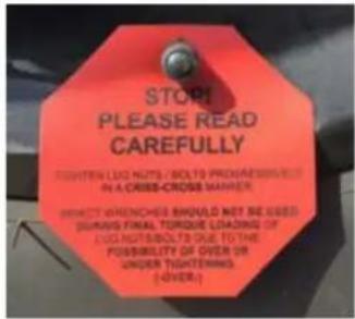
text_image
STOP PLEASE READ CAREFULLY BEETHEN LUX NUTS / BOLT TO PROGRESSIVE IN A CRISSE-CROSS MARKER. DIRECT WRENCHES SHOULD NOT BE USED SURASS FINAL TORQUE LOADING OF EXTRA BOLT TO DUE TO THE POSSIBILITY OF OVER OR UNDER TIGHTERING. (-OVER.)Take special care to ensure that the replacement lug nut is the correct type and size. While the threads of the v may match, the lug nut may be a size that does not hold the wheel securely against the hub, even when fully tightened. Be certain a replacement lug nut is an exact match for the original.
Ensuring that lug nuts on trailer wheels are tight and properly torqued is an important responsibility for maintaining your trailer in a safe operating condition. Inadequate and/or inappropriate lug nut torque (tightness) is a major reason that lug nuts may loosen during use. Loose lug nuts can rapidly lead to a wheel separation from the hub, with potentially serious safety consequences.
Check the lug nut tightness often, especially during the first few hundred miles of the trailer's use. You should always check the torque prior to beginning any long trip and every time a wheel is
removed and reset.
You must use a torque wrench to accurately indicate the amount of torque that you are applying to the lug nut. Four-way wrenches, ratchets, and similar tools can be useful for short-term emergency repairs but are not appropriate tools for accurately checking lug nut torque.
Keep a record of the date and approximate mileage when the lug nut torque is checked. Note any lug nut(s) that lost torque. Investigate the reason(s) if the lug nut torque is not maintained over more than one retightening because this indicates there is something potentially wrong with the lug nuts, nut studs, wheels and/or hubs and that should be corrected.
Contact an authorized MasterCraft dealer immediately if any persistent lug nut loosening (or any other lug, wheel or axle problem) occurs.
In the event of a wheel separating from the trailer during use, notify an authorized MasterCraft dealer. Seek prompt professional assistance in assessing the trailer and its gear, and retain but do not fuse involved lug nuts, wheels and studs. Do not repair or service the trailer yourself. Instead, call a trained, authorized MasterCraft service technician.
Use the following pattern to tighten lug nuts. On first torqueing pass tighten to 45 ft.-lbs. On second pass tighten to 70 ft.-lbs. On third pass tighten to 90 ft.-lbs. On fourth pass tighten to a reading between 110 ft. lbs-120 ft.-lbs. Follow the pattern shown in the photos at right.
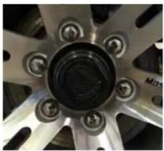
natural_image
Close-up of a car wheel rim with BMW logo and screw hub (no text or symbols on the rim itself)
natural_image
Close-up of a metallic mechanical component with multiple bolt holes and radial grooves (no text or symbols visible)Tires
The most common cause of trailer tire trouble is under-inflation. It is important, therefore, to always maintain correct air pressure as indicated by the tire manufacturer on the tire's sidewalls. (Tire pressure information may be listed on stickers elsewhere as a convenience, but because tires may be replaced, the air pressure should always be verified on the tire's sidewall. If there is a difference between air pressure listings on labels, warning stickers and tire sidewalls, always defer to the tire sidewall air pressure listing.)
Always check the air pressure when the tires are cold. Tires heat up and the air pressure increases after traveling short distances. For safety and convenience, inflate tires to the air pressure indicated on the sidewall of the tire, but always carry a spare wheel and tire in case of unexpected or sudden issues with a tire.
When trailer tires become worn or damaged, replace them with new tires. An authorized MasterCraft dealer can help you.
During times of storage, maintain the proper tire inflation, shield tires from UV rays (direct sunlight), and relieve the load on the tires by supporting the trailer frame with concrete blocks or jack stands.
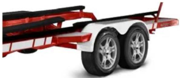
natural_image
Red and white flatbed cargo vehicle with two black wheels and red frame (no visible text or symbols)
WARNING
Keep tires properly inflated. Inspect each tire's pressure before each use. Refer to the tire sidewall for proper inflation. Failure to maintain the correct tire pressure may result in tire failure and loss of control, which may result in serious injury or death and/or property damage.
The tires that come equipped on the MasterCraft trailer were selected for durability as well as comfort and are matched to the trailer's specifications. Over time, as with all tires, there will be wear and eventually replacement will be necessary. At that time, do not mix radial and bias tires because it may affect the trailer/tow vehicle
handling and safety. MasterCraft dealers offer replacement tires; if the owner chooses to purchase tires elsewhere, be certain that the replacement tires meet the manufacturer's requirements and that they properly integrate with any tires remaining on the trailer.
Reading Tire Wear
The way your tires wear is a good indicator of how your trailer's various systems are integrating. Abnormal wear patterns are often caused by the need for simple tire maintenance or alignment. Tires should be inspected at every opportunity. Learning to read the early warning signs of trouble can prevent wear that shortens tire life or indicates the need for having other parts of the trailer serviced.
Tire Inspection Inspection Elements
• Visually inspecting the tires
• Feeling the tread by hand to detect tire wear such as feathering
- Checking all tires with a tire pressure gauge
Samples Of Abnormal Wear
Overinflation
Excessive wear at the center of the tread indicates that the air pressure in the tire is consistently too high. The tire is riding on the center of the tread and wearing it prematurely. Many times, the "eyeball" method of inflation (pumping the tires up until there is no bulge at the bottom) is at fault. Tire inflation pressure should always be checked
with a reliable tire gauge. Occasionally, this wear pattern can result from extremely wide tires on narrow rims. In such situations, tires or wheels will have to be replaced.
Underinflation
This is the most common problem in trailer tires. This type of wear usually results from consistent underinflation. When a tire is under inflated, there is too much contact with the road by the outer treads, which wear prematurely. Tire pressure should be checked with a reliable pressure gauge.
Feathering
Feathering is a condition when the edge of each tread rib develops a slightly rounded edge on one side and a sharp edge on the other. By running your hand over the tire, you can usually feel the sharper edges before you'll be able to see them. The most common cause of feathering is incorrect toe-in setting. If this is occurring, have the toe-in adjusted to a proper setting.
One side wear
When an inner or outer rib wears faster than the rest of the tire, the need for wheel alignment is indicated. This occurs when there is excessive camber in the axle, causing the wheel to lean too much to the inside or outside and putting too much load on one side of the tire. The trailer may simply need the wheels aligned, but misalignment could be due to sagging springs, overloaded trailer or an unbalanced load on multi-axle trailers. Because load has a great effect on alignment, be sure the trailer is loaded to balance the weight on the axle or axles. Trailers should be towed with the trailer in a level condition. This is particularly important with independent suspension trailers using torsion axles.
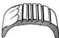
Cupping
Cups or scalloped dips appearing around the edge of the tread on one side or the other almost always indicate worn (sometimes bent) suspension parts. Adjustment of wheel alignment alone will seldom cure the problem. Any worn component that connects the wheel to the trailer (wheel bearings, springs, bushings, etc.) can cause this condition.
Worn components should be adjusted or replaced with new ones. The worn tire should be balanced and possibly moved to a different location on the trailer. Occasionally, wheels that are out of balance will wear like this, but wheel imbalance usually shows up as bald spots between the outside edges and center of the tread.
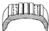
Second-Rib Wear
Second-rib wear is normally found only in radial tires, and appears where the steel belts end in relation to the tread. Normally, it can be kept to a minimum by paying careful attention to tire pressure and frequently rotating the tires. Some tire manufactures consider a slight amount of wear at the second rib of a radial tire to be normal, but excessive amounts of wear indicate that the tires are too wide for the wheels. Be careful when having oversized tires installed on narrow wheels.
Braking System
Disc brakes offer several advantages over drum brakes. Disc brakes have improved resistance to fade on downhill grades. They are self-adjusting, so as the pads wear, braking efficiency is not reduced. This type of brake recovers quickly after being submerged. They also require less maintenance, are easier to flush out, and are less susceptible to water-induced corrosion. The trailer's brakes are designed to energize automatically when the tow vehicle's brakes are applied. These are known as "surge brakes."
NOTE: Some jurisdictions do not allow surge brakes. Always check within the locality in which you will be towing.
When the vehicle slows down or stops, the forward momentum (surge) of the trailer against the hitch ball develops hydraulic pressure in a master cylinder inside the trailer brake actuator. Hydraulic lines are used to transfer pressure to the brakes and engage them.
In most states, trailers with a Gross Vehicle Weight Rating (GVWR) of 1,500 pounds or more are required by law to have brakes on all wheels. (Auto manufacturers generally recommend brakes even with lighter trailers.)

WARNING
Trailer brakes must be maintained in good working condition at all times. Inspect the brake system on a regular basis and verify proper fluid level in the actuator. The loss of adequate braking could result in serious injury or death and/or property damage.
The trailer is equipped with a hydraulic brake actuator. Trailer brakes will automatically apply whenever the tow vehicle's brakes are applied. Stopping (deceleration) force is developed in direct proportion to the stopping force generated by the tow vehicle.

WARNING
The breakaway system actuators will apply the trailer brakes if the trailer becomes completely detached from the tow vehicle while under power. Failure to properly connect the breakaway system prior to towing may result in serious injury or death and/or property damage.

natural_image
Close-up of a car tire and brake system with visible components (no text or symbols)(See breakaway cable detail earlier in this section of the Owner's Manual.)
The breakaway cable is a line of defense at separation. Before the breakaway cable is pulled, the coupler must become detached from the hitch ball and then the safety chains fail. At this time the
breakaway cable is pulled, which applies a braking force to the trailer. Note that the breakaway system is not intended to lock up the trailer brakes after separating from the tow vehicle but rather to apply just enough braking force to keep the trailer from free-wheeling. The breakaway system must be reset manually after it has been activated.
Surface rust may build up on the rotor brake surface if the trailer isn't used for a week or more. If this occurs, then generally the brake pads will wipe off the rust in the first few miles of travel. However, if the trailer has been idle for several months, or it has been frequently submerged in salt water and the brakes have not been flushed out (as described earlier in this section of Owner's Manual), severe corrosion can occur.
Try the brakes before each trip. On a regular basis, have the brake lines inspected, necessary adjustments made and any damaged or worn parts replaced by an authorized MasterCraft dealer.
Wet brakes usually do not hold especially well. If the wheels have been in water, several brake applications at slow speeds should dry them out. If the wheel assemblies have been submerged in salt water, it is important to flush the rotors and calipers thoroughly with fresh water to minimize subsequent corrosion.
If the stopping capacity does not meet expectations, have the tow vehicle and the trailer brakes checked for proper operation. The trailer brakes should be inspected by an authorized MasterCraft dealer.
Review the tow vehicle manufacturer's recommendations and instructions for towing.
If the brakes are hot, before launching your boat, it is a good idea to allow the brakes to cool first. The sudden change in temperature when submerging very hot calipers and rotors into water stresses all the related parts and could cause damage.
If you are unable to back up, check the electronically operated back-up valve on the actuator, which is connected to the tow vehicle back up lights. When energized, the valve opens and prevents pressure build up in the system. When it is energized by shifting the tow vehicle into reverse, you should hear a noticeable "click" sound. If you don't, check that the electrical connection between the tow vehicle and the trailer is secure.
When parking the trailer, be sure the actuator is fully extended. This position relieves pressure on the brakes. Corrosion sometimes causes actuators to freeze in the compressed position. This causes the brakes to drag and overheat during subsequent outings.
Recommended Brake Fluid
After only a year of use, used brake fluid in the average marine trailer may contain as much as two percent (2%) water. Over time, the percentage will continue to grow and may reach as much as eight percent (8%). As the concentration of moisture increases, a sharp drop in the fluid's boiling point temperature results. As little as one percent (1%) moisture can lower the boiling point to 369^ F/ 187^ C.
According to DOT and OEM requirements, brand new DOT 3 brake fluid must have a dry (no moisture) boiling point of at least 401°F/205°C, and a wet (moisture saturated) boiling point of no less than 284°F/140°C. (Most far exceed these requirements, fresh out of the bottle.) Older brake fluid (about 18 months) with even three percent (3%) moisture content lowers the boiling point to 293°F/145°C, which is dangerously close to the minimum standard requirements.
Water contamination increases the danger of brake failure because vapor pockets can form if the fluid gets too hot. Vapor displaces fluid and is compressible, so when the brakes are applied, the actuator may completely compress without applying the brakes!
In addition, water laden brake fluid promotes corrosion and pitting in caliper pistons and bores, wheel cylinders, master cylinders, steel brake lines and reverse solenoids.

WARNING
Consumers must use only DOT 3—preferred—or DOT 4 brake fluid. DO NOT USE DOT 5 BRAKE FLUID. DOT 5 FLUID WILL DAMAGE THE SEALS IN THE ACTUATOR AND CALIPERS, CAUSING FAILURE OF BRAKES THAT COULD LEAD TO INJURY OR DEATH. Any other type may not provide sufficient chemistry to protect against overheating. Brake fluid should be completely replaced during annual (at least once every 12 months or more often if the system has shown evidence of brake fluid loss) maintenance. Brake fluid types should never be mixed. Failure to provide required maintenance can cause brake failure, leading to incidents that result in serious injury or even death.
DOT 5 brake fluid is a silicone-based fluid and requires specific materials for the boots, seals and wipers in the actuator master cylinder and caliper. Those materials are NOT used in MasterCraft trailers. Regardless of marketing claims made regarding a supposed superiority of DOT 5 brake fluid, the fact is that it will cause significant failure in the trailer's brakes because it is not designed to use DOT 5 brake fluid.
"Unexplained" brake failures are often traced to dragging brakes caused by the E-stop cable being tripped or the use of DOT 5 brake fluid. The underlying cause most often is because the brakes got over-heated and caused the fluid to boil. This can occur when the fluid level is appropriate, the linings are within specifications, and the hydraulics appear to work properly.

WARNING
DO NOT USE DOT 5 brake fluid in any component of MasterCraft trailers. The silicone causes seals to swell and can bind up caliper pistons. Do not use this in individual actuators, disc brakes or solenoids.
The silicone in DOT S brake fluid also causes foaming bubbles when forced through small orifices under high pressure, such as the solenoid valves in a disc brake system. Bubbles in brake fluid result in spongy brakes. Silicone also tends to become slightly compressible at temperatures near its boiling point, which makes it generally inappropriate for trailers used in mountain conditions.
Brake Lockout
When backing up, the coupler will move back and apply the trailer brakes. The brakes will apply at different levels depending on how fast you back up, the type of brakes, the road or surface, and the position/angle of the trailer. All MasterCraft trailers have an electrical solenoid control to allow the trailer to back up. This control is wired to the back-up lights on the tow vehicle, and when the tow vehicle is put into reverse, this control does not allow the trailer brakes to apply.
Manual Brake Lockout for the Actuator
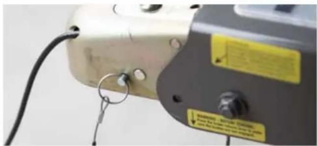
natural_image
Close-up of a mechanical device with visible wiring and a yellow warning label (no readable text or symbols)If the trailer needs to be moved while in reverse and without electrical connections to operate the reverse lock-out solenoid, the safety pin can be used to manually keep the coupler from applying pressure to the master cylinder. Place the pin in the hole at the front of the actuator housing. Remove the pin IMMEDIATELY after backing up and replace in the coupler position to lock the coupler.
Failure to do so will cause the loss of brake power when the trailer is towed.

WARNING
The reverse lockout option must only be used when moving in reverse. Immediately remove the pin prior to towing and fully insert it into the coupler latch.
Manual Bleeding Of Brakes

WARNING
The following procedure should be performed only by skilled mechanics. MasterCraft recommends that it be completed only by an authorized MasterCraft dealer.
Check that all hydraulic fittings are secure. Read and understand all instructions before starting. Two people are required for manual bleeding.
Remove the master cylinder reservoir cap and fill the reservoir with brake fluid. Use either DOT 3 (preferred) or DOT 4 automotive brake fluid. DO NOT USE DOT 5 BRAKE FLUID. DOT 5 FLUID WILL DAMAGE THE SEALS IN THE ACTUATOR AND CALIPERS CAUSING FAILURE OF BRAKES THAT COULD LEAD TO INJURY OR DEATH.
(See recommended brake fluid information in this section of the Owner's Manual.)
Follow the instructions on the brake fluid container. Avoid shaking the brake fluid container, and pour fluid slowly to minimize air entrapment. Let the fluid in the reservoir stand until it is completely free of air bubbles.
IMPORTANT: Before bleeding the brake lines, bleed the actuator master cylinder. This is mainly required if a new master cylinder has been installed, or if the master cylinder was run dry or is low on fluid. To do so, remove the plastic access cover on the top of the actuator housing and insert a flat blade screwdriver between the rear bracket/tab and the fixed tab. The fixed tab is between the rear bracket/tab and the front (E-brake release) tab. While holding down the front tab, and using a slow/controlled motion, cycle the screwdriver fore-aft to pump the master cylinder push rod
Start the bleeding procedure on the brake farthest from the master cylinder.
At the brake assembly, connect a transparent bleeder hose to the bleed screw fitting on the caliper and submerge the free end into a container partially filled with brake fluid. Do not reuse this fluid.
The first person should stroke the push rod slowly while holding the safety release bracket down. The second person opens the bleed screw fitting. Then close the bleed screw fitting BEFORE the first person SLOWLY releases the push rod. Repeat this procedure until the fluid expelled from the bleeder hose is free of air bubbles. Remember to always tighten the bleeder screw before releasing the push rod. During this procedure, the master cylinder reservoir fluid level must be maintained at no less than half full.
Repeat Steps 4 and 5 for the other brake, as well as the brakes on the front axle of tandem axle trailers, or the center then finally the front on triple axle trailers. If installation is on a tandem-axle or triple-axle trailer, repeat the bleeding procedure on the rear axle(s) brakes for a second time to assure purging of all air in the system.
Push down on the safety release bracket to ensure that the push rod is in the released position.
After the bleeding is completed, recheck the fluid level in the master cylinder. Fill the master cylinder reservoir to 1/8" from the bottom of the threads on the reservoir cap. Do not overfill.
As a final check after bleeding is completed, stroke the push rod and check to be sure the brake system is pressurized. This is done by attempting to rotate a tire around. It is highly recommended to check the function of the brakes prior to running down the road. Attempt to back-up the trailer (preferably up and incline) without the wiring harness connected. This should activate the brakes to verify they are working as expected. If an incline is not available, and with the wiring harness disconnected as well, attempt to back-up the trailer against a wheel chock hard enough to slide the actuator rearward into the frame and engage the brakes. Remove the wheel chock and continue to back up to verify the brakes are engaging.

CAUTION
Important: Do not use brake fluid drained from the brake system to refill the master cylinder reservoir as such fluids contain contaminants from the system that may result in brake failure or costly repairs.
Trailer Jack
MasterCraft recommends using the trailer jack to lift the coupling of a loaded trailer from the hitch ball. Rotate the trailer jack to the vertical position and engage the locking pin before placing a load on the trailer jack.
Like any mechanical assembly, the trailer jack requires maintenance to continue to function properly. The drive gear and the rack-and-pinion should be greased, and the caster and wheel bearings should be oiled frequently.
Failure to swing up the trailer jack and snap into towing position before towing may result in damage to the trailer.

WARNING
Failure to engage the locking pin may result in the collapse of the jack stand, which could cause serious injury or death.
Always be certain that the feet of individuals operating the trailer jack or in the vicinity of the trailer jack are clear when the jack is lowered into position. A considerable amount of the trailer's weight, and that of the boat when it is aboard the trailer, can be transferred through the trailer jack. This could cause very painful injuries if feet are not clear of the jack when it is lowered. Also be certain that fingers and hands are clear when moving the trailer jack because they can be pinched in the mechanism, again resulting in injury.
Tie Downs
natural_image
Three-panel photo showing mechanical components with no visible text or symbolsEnsuring that a MasterCraft boat will be held securely in place on the trailer's hull support (bunks), especially when towing, is extremely important. If the boat is not firmly and properly secured, the boat can be damaged as it bounces against the hull supports.
MasterCraft offers the Ramp-N-Clamp system to simplify loading and launching the boat from the trailer. To operate:
Set the Ramp-N-Clamp handle to the down position so it can catch the boat when loading onto the trailer.
Lift the Ramp-N-Clamp handle to the up position to release boat from the trailer.
Do not lift the Ramp-N-Clamp handle until you are ready to release boat from the trailer.
Helpful Tips
For easier release on the ramp, put the boat in forward gear or keep the winch strap tight while lifting the Ramp-N-Clamp handle.
Keeping the Ramp-N-Clamp cover and front of the boat waxed is part of the proper, regular maintenance.
If the boat rocks back and forth on the trailer while towing, raise the winch post uprights or add tie down straps to trailer to prevent rocking. An ill-fitting trailer will cause wear that is not covered under the warranty.
A winch strap must be used and be firmly tight while towing. This prevents wear to the bow eye that is not covered under warranty. Maximum boat weight 8500 lbs.
Also, it is very important to be sure that the transom of the MasterCraft boat is resting fully and securely on the supports provided at the rear end of the trailer, and that it remains in place when the trailer is parked or underway.
Tie-down eyes have been added on both the bow and transom of the boat and must be used while trailering. Buckles at the back of the trailer must also be secured to the boat prior to towing.
Hitching Up
- Hitch only to the ball size marked on the coupler, which is two inches (2"). For all models except the X26 which is 2 5/18"
- Be certain that the ball clamp captures the ball.
• Cross the safety cables under the coupling.
Allow only enough slack in the safety cables to permit tight turns while towing. When hitching the trailer up, always observe each item on the Trailer Checklist found in this Owner's Manual. Hitching the trailer to the tow vehicle may be performed by just one person, but it is definitely easier with a second person to help guide.
Trailer Hitching Steps
- Slowly back the tow vehicle as close as possible to the trailer. It's easier—and safer—than pulling the trailer to the car or truck.
- Check to be sure the coupler locking device is released.
-
Raise the front end of the trailer with the trailer jack, position the coupler directly over the hitch ball and lower the trailer with the trailer jack until it is all the way down onto the hitch ball.
-
Check under the coupling to be certain that the ball clamp is below the ball and not riding on top of the ball.
- Lock the coupler to the hitch ball. To confirm that the coupler is locked onto the hitch ball, lift up on the trailer using the jack. If the trailer coupler comes loose from the hitch ball, unlock and go back to the third step above.
• After the coupler is properly locked on to the hitch ball, be certain that the trailer jack is in the fully raised and locked position. - Attach the surge break-away cable to the tow vehicle, making sure there is enough slack for tight turns.
- Attach the safety cables.
- Connect the trailer's seven-wire connector to the seven-wire connector of the tow vehicle and check the operation of the trailer lights.
Trailer Tips And Techniques
With a boat trailer in tow, an operator will be driving down the road with a vehicle combination that is longer, heavier and sometimes wider and taller than the tow vehicle. This means the operator should make a few adjustments to normal driving practices to compensate for the differences.
Use common sense
MasterCraft cannot anticipate every type of situation in which drivers may find themselves. The following recommendations apply to general situations, but it is up to the individual driver to properly and safely act or react as a given situation requires.
Take a shakedown cruise.
Before making the first major trip or lake cruise with a MasterCraft trailer, make at least one short trial run to become familiar with its handling characteristics.
Be sure everything is working properly
Slow down
There is less strain on the tow vehicle, trailer and boat at moderate to slow speeds. Also, many states have lower speed limits for vehicles towing trailers. Driving at moderate speeds will place less strain on the tow vehicle and the trailer. Trailer instability (sway) is more likely to occur as speed increases. Particular attention needs to be given to all aspects of towing when traveling over bumpy roads and railroad crossings.
Allow extra time and space
You'll need more of both when passing and stopping.
Pass with extra care
Signal well in advance and make sure you allow extra distance to clear the vehicle you are passing before you pull back into the lane. Pass on level terrain with plenty of clearance. Avoid passing on steep up or down grades. Down shift as necessary to improve acceleration or speed maintenance. When passing on narrow roads,
be careful to avoid soft shoulders. Running on soft shoulders could cause the trailer to jack-knife or go out of control.
Avoid sudden steering maneuvers
These may create sway or undue side force on the trailer. To control swaying caused by air pressure changes and wind buffeting when larger vehicles pass from either direction, release the accelerator pedal to slow down. Keep a firm grip on the steering wheel.
Allow considerably more distance for stopping
There is considerably more weight to be maneuvered, and even though your trailer is equipped with a braking system, it is highly likely that additional room will be needed in order to execute slowing or full stops.
Check the rear view mirrors
If not already equipped with them, install outside rear view mirrors on both sides of the tow vehicle. Make it a habit to check the mirrors at frequent intervals to be sure the trailer and boat are riding properly.
Swing wider
Trailer wheels are closer to the inside of turns than the wheels on the tow vehicle. This means swinging wider at curves and corners, will be required to prevent impacts between the trailer and other objects.
Do not control trailer sway by using vehicle brakes
Especially avoid jamming on the brakes hard. Generally, this type of action makes the sway worsen.
Pay attention to wind
Be prepared for sudden changes in air pressure and/or wind buffeting when larger vehicles pass from either direction. Slow down a little and keep a firm hand on the steering wheel.
Do not tow with folding tower in the DOWN position
Towing the boat with the tower in the UP position prevents premature wear. If the boat is equipped with a Bimini top, the top should be closed. If the tower has board racks, be sure that the board racks are folded to the inside.
Conserve fuel
Wind resistance against the boat and trailer can reduce gas mileage significantly, especially at higher speeds.
Avoid sudden stops and starts
Even though the trailer has brakes, a sudden stop can cause it to skid, slide or even jack-knife. (Be especially careful to avoid the necessity for quick stops while turning.) Smooth, gradual starts and stops will improve gas mileage and put less strain on the tie-downs, etc.
Signal your intentions
Well before stopping, turning, changing lanes or passing, use turn signals to let other vehicles know what you intend to do.
Drive in tow vehicle manufacturer recommended gear
If the tow vehicle has a manual transmission, traveling in lower gears when going up steep hills or over sand, gravel or dirt roads will ease the load on the engine and transmission. When driving on long downhill grades, try to avoid downshifting. Running in a low gear going downhill, which uses the engine as a brake, can actuate the trailer's surge brakes continuously for the duration of the grade, causing them to over-heat. A better procedure is to slow down before the start of the down grade and maintain a controlled downhill speed with repeated application and release of tow vehicle (and thus, the trailer) brakes. This technique permits the brakes to cool down between applications and provides for reserve braking capacity in an emergency. On moderate and steep sections, downshifting into lower gears may be unavoidable. Slowing down is important to allow the brakes to avoid overheating. Don't hesitate to pull over when possible during or after severe braking situations and allow the system to cool down. Running a stretch of highway where braking is not necessary is the quickest way to cool down the brake system because it allows a significant volume of air to flow through the vented rotors and over the brake pads to cool them.
Always be courteous
Make it as easy as possible for faster-moving vehicles to pass you. Remain in the slower lane and be prepared to reduce speed if they need extra time to return to the lane.
Do not tailgate
Allow at least one combined car and trailer length between you and the car ahead for every 10 mph you are traveling.
If a problem occurs, stay calm
Do not panic and do not do anything anymore suddenly or violently than is necessary.
Sudden bumping or fish-tailing may be a flat tire
Do not jam on the brakes or mash the accelerator to try to drive out of it. Stop slowly and in as straight a line as possible. If conditions permit, allow the trailer and tow vehicle to coast at a very slow speed and try to avoid braking, except when the wheels are straight ahead and the trailer and tow vehicle are in line.
If the trailer begins to fish-tail under acceleration to highway speed, back off the accelerator a little, and it should cease. If it begins again upon acceleration, stop and check the load. If the load is not evenly distributed, or if it is too far back so that the hitch load becomes too light, the result can be fish-tailing. Redistribute the load before continuing.
Launching Tips and Techniques
Every MasterCraft boat owner develops his or her own favorite launching technique.
Check the ramp first
Whether launching from an unimproved or surfaced ramp, check it out before starting the launch procedure. How steep is it? Is the surface firm enough to support the weight of the trailer and tow vehicle? Is it wide enough? How deep is the water at the end of the ramp?

CAUTION
Use great care when walking, standing or loading and unloading boats on or around any launch ramps because some launch ramps may be slippery when wet.
Prepare for launching
Install the drain plugs and detach the trailer tie-downs.
Slowly back the trailer down the ramp
If possible, have someone stand to one side of the ramp to provide directions. Backing up a trailer can be tricky. A good way to simplify the procedure is to grasp the steering wheel with one hand at its lowest point (8 o'clock). To make the trailer go right, move your hand on the wheel to the right (move the wheel counter-clockwise); to make the trailer go left, move your hand to the left (move the wheel clockwise).
Slowly back the trailer into the water until the transom floats 4"+ off of the trailer. The depth of the trailer to achieve this will vary depending on ramp angle. Set the parking brake and shift into park (automatic transmission) or first gear (manual transmission). Shut off the engine. Unlock the Ramp-N-Clamp (where equipped) latch and winch hook; then back the boat off the trailer.
To reload the boat on the trailer, simply reverse the above procedures, including setting your Ramp-N-Clamp to the proper position, and drive the boat onto the trailer at a slow pace. Before loading, clean any dirt or sand off the rollers and bunks. Sand on these can abrade the boat's bottom while on the road. Be sure to back in and completely wet the trailer bunks, then pull forward to the loading position.
Be certain all the boat tie-downs are properly fastened down before departing from the launching ramp area. Proper loading depth on trailers will vary with conditions, but a good starting point would be the same as launch depth or slightly higher.
NOTE: After the launch depth has been properly determined, apply a strip of reflective tape at the water level on each guide post. That will allow launch depth to be easily repeatable.
For the X10, X30, X46, NXT20 and ProStar trailers, it is important to back the trailer deeply enough into the water to load the boats so that the hull does not impact the back edge of the center bunk boards during loading. If the boat is loaded in too shallow conditions, it increases the possibility of causing
damage to the boat and/or the trailer. Such damage is not covered under the limited warranty.
The hull geometry and strake design/configuration make the X10 and X30 boats more sensitive to the loading depth of the trailers. The strakes are closer together, flatter and come forward farther than most early model MasterCraft boats. In addition to these features, the V-bow makes it more likely to approach the trailer off centerline. (The pickle-fork geometry on other boat model hulls helps align the front of the boat in the center of the trailer while approaching.) These factors influence the need for more care.
Through testing, it has been determined that the trailer should be backed in to a minimum of the below measurements on the guide pole (from the step height up to the guide pole measurement). It is suggested that some sort of visual indicator be placed on the guide poles as suggested in the note above.
| Boat Model | Wheel/Tire Profile | Ramp Type | ||
| Flat No | mal Steep | |||
| X10 | Standard 18" 22" 25" | |||
| Low 16" 20" 23" | ||||
| X30 | Standard 18" 18" 18" | |||
| Low 16" 16" 16" | ||||
Please bear in mind that these are recommended depths as measured under conditions at the factory-based lake. Adjustments may be necessary, depending on load distribution in the boat as well as the angle of the ramp where the boat is being used.
Power loading is always possible, but winching on the last few inches may be necessary, depending on the steepness of the ramp. As with most boats including the X10 and X30, if the trailer is backed in too far on a particularly steep ramp, the bow can easily go under the bow roller. Approaching the trailer very slowly (typically in neutral) is recommended.
Unloading depth can (and should be) somewhat deeper than these recommended LOADING depths, as the bunks are not needed to guide the boat off the trailer. Power unloading can burn the carpet in the same manner as power loading.

CAUTION
Following loading, wet brakes may not hold and/or may cause brakes to have diminished performance characteristics. A few braking applications at a slow speed will help to dry them out. Extra care must be used when braking after brakes have become wet.
Towing Requirements
States and municipalities may require special permits and licenses based on the size and weight of your trailer. Some states require additional equipment for the tow vehicle, such as side and rear view mirrors. Inquire at your local motor vehicle administration office to find out what requirements affect you.
If you plan to travel in another state, don't forget to check requirements there also. In addition to licenses and permits, there may be weight, height and width limits for using certain roads, bridges and tunnels. Also, be aware of restrictions regarding the transport of gases or fuels in tunnels.
And don't forget to contact your insurance company to make sure you have proper coverage for all types of towing situations. Some jurisdictions may also require liability insurance. If you have a loan for the trailer purchase, your lender may also require insurance.
Trailer Checklist
Before towing the vehicle, be sure to read and familiarize yourself with the instructions and warnings supplied with it.
Never Tow This Vehicle Before Safety Checking
• Coupler, hitch and hitch ball are of the same size
- Breakaway cable is properly attached to the tow vehicle
- Coupler and safety chains are safely secured to the hitch of the tow vehicle
• All fasteners are properly tightened
- Boat is securely tied down to trailer (winch line is not a tie down)
- Wheel lug nuts are properly tightened
- Wheel bearings are properly adjusted and maintained
- Load is within the maximum load carrying capacity
- Load inside the boat is properly distributed
• Tires are properly inflated
- All trailer lighting is working properly
- Trailer brakes are properly adjusted and working (if trailer is so equipped).
- Tower on the boat (if so equipped) is secure, whether it is upright and locked in place or has been lowered
- Sufficient overhead clearance before removing the boat/trailer from cover, or when towing so that the unit will clear any overhead items such as trees, bridges, overhead power lines, overpasses, etc.
This trailer is manufactured to meet the applicable federal safety standards at the time of manufacture. Check the local and state requirements regarding any additional equipment that may be required.
NOTE: Trailer laws covering such things as brakes, lights, safety cables, licenses, etc., will vary from state to state. Be sure that the trailer is in full compliance with applicable state laws. An authorized MasterCraft dealer can help in this regard. Otherwise, contact the nearest state motor vehicle department.
Maintenance
NOTE: Failure to follow these routine procedures may result in failures that are not covered under warranty.

WARNING
Failure to follow maintenance procedures as outlined in this Owner's Manual may result in component failure. Such failure is not covered under warranty. Failure may also result in loss of control or other malfunction that could potentially lead to serious injury or death!
Hose off the brake rotors and calipers, along with all other parts of the trailer that have come in contact with salt water or brackish water, as this will minimize corrosion. A fresh water flush of the system is the most critical aspect of trailer maintenance.
Extremely thick, heavy rust on rotor surfaces will not allow the wheel assembly to rotate freely, resulting in heat build-up and premature wear on components. Clean or replace components as necessary.
Brake pads must be replaced when 3/32" (.094") or less of the pad friction material is left.

WARNING
Brake pad replacement should be performed by an authorized MasterCraft dealer. Improper pad replacement may decrease braking effectiveness, potentially resulting in a collision as a result of failure to stop the tow vehicle within an acceptable distance.
Rotors should be resurfaced by a qualified brake specialist if extreme galling or wear marks are present.

WARNING
Worn rotors must be replaced. Failure to do so may result in brake failure, which may cause serious injury or death.
Be certain that hydraulic fluid is clean and the fluid level is within 1/8" from the bottom of the threads on the reservoir plug. (See the Actuator and Axle information contained in this section of the Owner's Manual.) Do not fill beyond that level. Brake systems use DOT 3 (preferred) or DOT 4 hydraulic fluid.
DO NOT USE DOT 5 BRAKE FLUID. DOT 5 FLUID WILL DAMAGE THE SEALS IN THE ACTUATOR AND CALIPERS, CAUSING FAILURE OF THE BRAKES THAT COULD LEAD TO INJURY OR DEATH.
NOTE: Care must be taken to avoid brake fluid coming in contact with the trailer paint. Brake fluid will damage paint! Such damage is not covered under warranty!
Check for leaks in the brake lines and fittings. Leaks will lead to loss of trailer braking ability. Present the trailer to an authorized Master-Craft dealer for repair if lines or fittings appear to be leaking.
Aluminum wheels also require attention to routine maintenance, particularly in keeping them clean. Failure to do so may result in damage that is not covered by warranty.
The trailer and wheels should be washed weekly during boating season, and after every use if the trailer has been submerged in salt or brackish water. Use a soft brush, mild detergent and/or mild degreaser. A quality spray-on wheel cleaner may also be used.
Ensure that any product used is specifically indicated for use on aluminum. (Many cleaners are too harsh and will result in pitting or other damage to the wheel surface.) Many car washes use strong chemicals and should be avoided when that is the case. Removing road film, contaminants and brake dust (all of which retain moisture) is critical to ensuring that the wheels will retain their luster and quality finish for a long period of time. Any exposure to a hard winter climate, particularly road salt and/or chemicals, requires immediate cleaning the same as submersion in salt water.
NEVER CLEAN HOT WHEELS.
Allow wheels to cool or cool them with running water. If the wheels are too hot, significant damage can occur to the wheels. It is also important to seal the wheels with a sealant that reduces static and resists brake dust. Check at an automotive supply store for an appropriate sealant.
Before Initial Use
Read this entire Owner's Manual completely.
Before Every Trip
- Ensure that all vehicle and trailer maintenance has been performed as set out in this Owner's Manual and the various other manuals, including the tow vehicle's owners manual.
- Verify that the tongue weight and load are within proper specification. Further, be sure that the load distribution is correct so that the tow vehicle and trailer are properly balanced front-to-back and side-to-side.
- Check the brake fluid reservoir to ensure it has the proper fluid level.
- Examine the brake rotor surfaces and remove excessive rust, flushing the brakes if the trailer has been idle for an extended period of time or submerged in salt water and not flushed afterwards.
- Examine the actuator for wear, bent parts, corroded/seized parts or other damage.
- Test the actuator to verify the brakes are working prior to use.
-
Verify all running lights and brake lights, turn signals and hazard lights, are working properly and that all wiring is properly connected. The wire harness must not be touching the road, but loose enough to make turns without disconnecting or damaging the wires.
-
Verify the coupler latch and all equipment that connect the trailer and tow vehicle are properly secured and adjusted.
- Verify that there are no leaks in the hydraulic system.
- Verify the safety cables are properly attached to the tow vehicle.
- Verify the emergency brake cable is attached properly to the tow vehicle.
- Verify the boat is properly loaded on the trailer and properly tied down to the trailer.
- Verify and/or correct tire pressure on both the tow vehicle and trailer.
- Ensure the lug nuts are properly torqued. (This must also be done after the first 25 miles of towing and every 100 miles thereafter, at a minimum. MasterCraft recommends checking this more often. At each fuel or rest stop is not excessive.)
- Verify the wheel jack is retracted and in the locked position prior to towing.
- Verify the tow vehicle has not exceeded the load capacity prior to towing.
- Check the guide pole bars to ensure they are tight.
- Check that all items are securely fastened on and in the trailer.
Every Three To Six Months Or 250 Miles, Whichever Occurs First (In Addition To Above)
- Grease the trailer jack.
- Oil the trailer jack handle in accordance with the manufacturer's recommendations.
- Examine the entire trailer for any abnormalities or damage.
- Examine the trailer bunks for any signs of abnormal wear.
- Lubricate all the rollers on the trailer with a light coat of oil.
Annually Or Every 2,000 Miles, Whichever Occurs First (In Addition To The Above)
- To assure the bearings are in good working order, check the bearing adjustment at least once a year by following this procedure: Jack up one side of the trailer. (Be certain to use jack stands and check the trailer wheels to keep the trailer from moving during the inspection.) Grip the edge of the tire and see if it can be rocked or moved. If the outer edge of the tire moves more than 1/8" at all, the bearings may need to be readjusted.
- Inspect the tow hitch for corrosion or damage. Repair or replace components as necessary.
- Check for wear on the hitch ball. If the ball is worn, it is UNSAFE and must be replaced.
- Check the coupler mechanism for smooth operation. If the latch handle does not spring open after being disengaged, lubricate the points on the coupler latch mechanism.
- Check the actuator for excessive wear. If the outer member is rubbing against the inner, wear marks will show on top of the coupler just forward of the outer member. Contact an authorized MasterCraft dealer for replacement parts.
- Check the actuator travel. Excessive actuator travel (over one inch) when the brakes are applied indicates air in the brake lines.
- Check the brake fluid in the master cylinder reservoir. On the actuator, remove the cap to the master cylinder reservoir by unscrewing the cap in a counter-clockwise direction. The brake fluid level should be 1/8" below the threads.
-
Check for foam or bubbles in the brake fluid. If either is present, drain the fluid from the master cylinder and replace with ONLY new brake fluid of the same type (DOT 3 is preferred—or DOT 4).
-
DO NOT USE DOT 5 FLUID. (See specific information in Recommended Brake Fluid in this section of this Owner's Manual.)
- In order for brakes to function properly, all air must be expelled from the brake system. If bleeding is necessary, have an authorized MasterCraft dealer perform this function or follow the manual bleeding of the brake system instructions as outlined in this Owner's Manual. It is imperative that the system be filled with only ONE type of brake fluid. Different types do not mix. Follow the instructions on the brake fluid container.
- Check the safety chains and attachment points for damage or wear. Repair or replace as necessary.
- Check the breakaway cable for worn or frayed cable strands. End fittings should be checked for damage. Replace as necessary.
- Check for any hydraulic leaks in the brake system. Be sure all tube fittings are tight. Periodic checks must be made on all hoses, brake line tubing and fittings to guard against cuts, worn hoses and loose fittings that may cause leaks in the trailer brake hydraulic system. Replace deteriorated and damaged parts as necessary.
- Check for chips and nicks in the paint. Touch up as necessary. Ignoring this will lead to accelerated wear and deterioration of the trailer.
- Check the condition of the bunks. If the coverings show wear, discuss with an authorized MasterCraft dealer. If the coverings are not in good condition or if the bunk sub-frame shows any damage, this will adversely affect the fit of trailer to boat. This can result in damage to the boat hull, which is not covered under warranty.
Storage (For Several Months)
- If at all possible, park the boat trailer in a protected, covered area such as a garage, carport or similar shelter. Keep all canvas covers on the boat while stored, but in higher humidity areas or periods of weather, it may be necessary to open a corner of the covered area to allow air circulation. See the Care and Maintenance section of this Owner's Manual for additional information and suggestions regarding storage procedures.
- Have the wheel bearings checked by an authorized MasterCraft dealer prior to reuse.
- Loosen the tie-downs and winch strap, but be sure the boat is still resting properly on the hull supports (bunks).
- Remove the drain plug and elevate the trailer tongue slightly (just an inch or two) to allow water to drain out so the boat will be dry. Tie the drain plugs from the boat's bilge system to something obvious such as the steering wheel so that they will be easy to remember to re-install before the next outing.
- A good time to touch up rust spots, nicks and chips is when the trailer is in storage.
- Replace damaged tie-downs, winch straps, wiring, etc.
- Maintain proper tire inflation.
- Shield tires from UV rays (direct sunlight).
- Relieve the load on the tires by supporting the trailer frame with concrete blocks or jack stands.
- Lubricate moving parts such as the rollers and winch, as well as the ball coupler.
- Tighten any loose nuts and bolts.
Extended Storage (In Excess Of One Year)
Follow the recommendations listed above for storage of several months duration. Additionally:
- Check the brake system for fluid level in the master cylinder. If the fluid level is low, air may be trapped in the brake lines. Bleed all lines if necessary and fill the reservoir to the proper level.
- Lubricate all links and pivots to prevent rusting.
- Fill the frame (to avoid damage from vermin).
- Be certain the breakaway system has not been set and that the actuator is fully extended.
- When possible, store away from excessive moisture.
Troubleshooting

WARNING
If any of the following potential problems develop, the trailer must be immediately stopped and the proper corrective action taken before the trailer is placed back in service. Failure to do so may lead to loss of proper trailer braking capability or damage to the trailer and load.
Coupler Latch Handle Not Opening Or Closing Easily
| Possible Cause Remedy | |
| Ball not fully inserted in ball socket | Check for the proper ball size and positive tongue load. Check to see if the tongue jack is fully retracted. Make sure there are no foreign objects or excessive points inside the coupler cavity. |
| Trailer and tow vehicle not level with each other or facing downhill | Reposition the tow vehicle and trailer or block a trailer tire and extend the actuator. |
| Oversize hitch ball Check ball size at several positions.The ball should be within 1.970" - 2.000" in diameter. Replace if necessary. | |
| Excessive corrosion Lubricate or replace parts as necessary. | |
| Ball clamp interference | This condition can occur on certain styles/types of ball mounts. Replace as necessary, or lift the coupler slightly to enable the clamp to slide past the interference, then let the coupler back down. |

WARNING
If the latch handle does not close freely, DO NOT tow the trailer until locating and correcting the cause of the problem. Forcing the latch handle closed will make opening the latch handle extremely difficult.
Squeaking, Clunking And Clattering At The Actuator
| Possible Cause Remedy | |
| The hitch ball requires lubrication | Lubricate with conventional multi- purpose lubricant or commercial lubricant made for hitch balls. |
| Loose hitch ball inspect | the hitch ball and tighten. |
| Loose hitch Inspect the | hitch and repair. |
| A worn or too small hitch ball | Replace the hitch ball with a quality unit that meets SAE specifications. |
| Air in the brake lines, allowing the actuator to travel too far | Check for leaks and re-bleed the brakes. |
| Trailer equipped with “free backing” brakes | Clunking noise is typical for these types of brakes as long as braking performance is normal. |
When Braking, Brakes Repeatedly Come On And Release. Braking Is Not Smooth, Called “Chucking”
| Possible Cause Remedy | |
| Loose hitch or ball Correct as necessary. | |
| Not enough tongue weight or shocks on tow vehicle too soft | Correct as necessary. |
| Air in the brake lines. Bleed the brake lines. | |
| Contaminated brake linings. | Fix the cause of the contamination, which will likely be a leaky wheel cylinder or hub grease seal. Replace the linings and clean the braking surface on the rotor. |
| Corroded master cylinder bore or rust from the brake line | Replace the actuator master cylinder. |
| Breakaway cable has been pulled | Reset the push rod release bracket. |
| Brake line kinked Eliminate the kink. If found on a steel brake line, the line should be replaced. | |
Brakes Not Operating Or Performing Poorly
| Possible Cause Remedy | |
| Worn out brake shoes or disc brake pads | Replace the brake shoes/pads on both sides of the axles and check the drums/rotors for wear or damage. |
| Foreign material in the brake unit assembly | Clean thoroughly. Replace the shoes and linings if contaminated. |
| Insufficient amount of hydraulic fluid. | Fill the reservoir and bleed the brakes. Check for leaks. |
| Broken lines or pinched line | Replace faulty lines and bleed the brakes. |
| Seized actuator master cylinder prevents piston from stroking | Replace actuator master cylinder. |
| Corrosion/rust keeps brake from operating | Replace damaged components or entire brake assembly as required. |
One Brake Is Overheating
| Possible Cause Remedy | |
| Disc brake caliper does not permit the brake pads to release. | Check the caliper. Sections must be free to move apart. If frozen in place, remove and free it up. Caliper piston may freeze up and prevent pads from retracting. Clean contaminants out of the piston cavity. Replace the piston, seal and protective dust cover boot. Bleed the brake system. |
| Damaged or frozen brake mechanism | Rebuild or replace the brake unit. |
More Than One Brake Is Overheating
Isolate the problem to the actuator or the brakes by:
• Fully extend the actuator.
- Remove the master cylinder reservoir cap.
- Check that the reservoir is properly filled.
- Manually push the actuator inner member in or use a screwdriver to stroke the push rod.
- In the first 1/8" of stroke, the reservoir fluid will either remain completely calm or will swirl around. If the fluid swirls, then this indicates that fluid is being allowed to return to the reservoir when the actuator is extended. This means that the actuator is functioning properly and it is necessary to further troubleshoot the brakes to determine the cause of overheating.
- If the fluid is not disturbed, as described above, it means the brake system is remaining pressurized and there is a problem with the actuator. Troubleshoot the actuator to determine the cause of the problem.
Potential Issues With the Actuator Include
- The fluid return hole in the master cylinder is clogged or is not correctly positioned
- Corrosion in the master cylinder is freezing the piston or not allowing it to fully retract, which is usually caused by a trailer being stored with the actuator compressed
- Some other malfunction or damage that is keeping the master cylinder from retracting.
| Possible Cause Remedy | |
| Trailer has been stored with the actuator compressed and rust has caused the brakes to freeze up. | Remove the brakes. Clean, repair or replace the components as necessary. This is best done by an authorized MasterCraft dealer. |
| Pinched or kinked brake lines. | Check the brake lines and replace as necessary. |
| Pulled breakaway cable and the push rod has not been reset. | Reset the breakaway cable. |
LIMITED WARRANTY STATEMENT
-
Disclaimer and Limitation of Implied Warranties. The express limited warranty set forth herein is in lieu of all other warranties and representations, express or implied, and to the maximum extent permitted by applicable law, MasterCraft disclaims, and the owner hereby expressly waives, any and all other warranties or representations of any kind or nature, including, but not limited to, implied warranties of merchantability and fitness for a particular purpose, other than those warranties which are implied by, and are incapable of exclusion, restriction or modification under applicable law. The term of any implied warranties that cannot be disclaimed under applicable law, including, but not limited to, implied warranties of merchantability and fitness for a particular purpose, shall be limited to the duration of the express warranty periods applicable to the respective components. Some states do not allow the exclusion of implied warranties and/or do not allow limitations on the amount of time an implied warranty lasts, so the above limitations may not apply to you. This limited warranty gives you specific legal rights. You may have other rights which vary from state to state.
-
Limited Warranty and Term, MasterCraft Boat Company, LLC. ("MasterCraft") warrants to the original retail purchaser that the following components of each new and unused boat manufactured by MasterCraft shall be free from material defects in materials and workmanship to the extent set forth below, under normal use and when operated and maintained in accordance with MasterCraft's instructions, beginning on the date of the original retail purchase of the boat by purchaser from an authorized MasterCraft Dealer for the period indicated in this Section 2:
2.1 Deck, Hull, Liner and Stringers. The deck, hull, liner and stringer system (collectively, the "Structural Components") are warranted for as long as the original purchaser owns the boat.
2.2 Gel Coat. On condition that the consumer has provided proper maintenance and care as described in the Corrosion and Cleaning the Boat sections of the MasterCraft Owner's Manual, the gel coat, which is applied to all MasterCraft boats at the factory, will be warranted for a period of one (1) year from the date of the original retail purchase of the boat or the initial use of the boat, whichever first occurs, for stress crazing of the gel coat. However, no warranty is provided and MasterCraft expressly disclaims any warranty for scratching, discoloration or fading of the gel coat. The reason for this limitation and exclusion is because environmental operating conditions and customer maintenance/care are factors that have a significant effect on the condition and durability of the gel coat and are factors that are outside of MasterCraft's reasonable control.
2.3 Other Component Parts. All other components of the boat not specifically referenced in Sections 2.1 through 2.2 hereof are warranted for a period of five (5) years.
2.4 Trailer and Trailer Component Parts. All components are warranted for a period of five (5) years, with the exception of the trailer paint, which is warranted for a period of one (1) year, from the date of the original retail purchase of the trailer or the initial use of the trailer, whichever first occurs.
2.5 Warranty Period. All express warranties are for the applicable
time periods set forth in this Section 2, unless a longer warranty period is required by applicable law, in which case such longer warranty period will apply. MasterCraft's boats and trailers are manufactured by MasterCraft in model years which run from July 1 of a given year through June 30 of the immediately following year (a "Model Year"). The start date for the warranty periods shall be deemed to be the earlier of the date of the original retail purchase of the boat or the date that the boat was first used by purchaser, whichever first occurs. Some component manufacturers warrant their product for periods exceeding the time limits stated herein. MasterCraft administers warranty within the limits specified in this Limited Warranty Statement only, but will provide contact information in applicable circumstances to consumers upon request.
-
Warranty Conditions, Limitations and Exclusions. MasterCraft boats are manufactured by trained crafts-persons from high-quality materials and components. However, conditions outside of MasterCraft's control require specific limitations on, and exclusions from, coverage under this Limited Warranty. The Limited Warranty on the Structural Components set forth in Section 2 of this Warranty does not cover or include any other components fastened or applied to the hull or deck. This Limited Warranty constitutes the final, complete and exclusive statement of warranty terms, and no other person or entity is authorized to make any other warranties or representations on behalf of MasterCraft. Furthermore, the Limited Warranty set forth in Section 2 (including all subsections) hereof does NOT cover any of the following:
-
Damage caused by misuse, negligence, accident, collision or impact with any object;
- Damage caused by any improper alteration or modification to the boat or any of its component parts or accessories, including damage resulting from alteration, modification, repair or replacement in such a way as to increase the cubic-inch capacity or horsepower output of the engine and boat as originally manufactured;
- Damage caused by the use of improper or contaminated fuel or fluids;
- Damage caused by the use of customer-applied chemicals or accidental spills;
- Damage caused by failure to maintain the boat in accordance with the maintenance provisions in the owner's manual or improper maintenance of the boat;
- Damage caused by the failure to comply with any recall or request for repair;
- Damage resulting from the use of the boat for any racing, speed, commercial competition or performance demonstration;
- Damage resulting from use of the boat for rental, commercial or industrial purposes;
- Damage to hardware and other components fastened or adhered to the hull, deck or liner;
- Damage caused by fire, theft, freezing, vandalism, explosion, lightning, wind, hail storms, flooding or other natural disaster;
- Damage caused by use of any non-MasterCraft trailer;
- Damage caused by improper support of the boat on davits, a hoist system or boat lift of any kind;
- Damage to paints, varnishes, gel coat surfaces and colors, chrome-plated or anodized finishes, floor and floor covers and
any other surface coatings, as well as damage due to in-water storage without proper barrier coat and bottom paints.(Note: although MasterCraft uses the highest grade gel coat materials, a condition may develop where the bottom of the boat may show signs of discoloration and/or blisters if the boat is left in the water for long periods of time, i.e., in excess of thirty [30] days; therefore, a proper barrier coat and bottom paint should be used whenever it is anticipated that the boat will be left in the water for an extended period of time, i.e., in excess of thirty [30] days);
- Damage to the trailer and its parts or components due to abrasions, rock chips, rust, improper care or maintenance, or use in salt or brackish water;
- Damage caused by dealer-installed options or accessories;
- Damage caused by consumer-installed options or accessories;
4. Commercial Boat Warranty Conditions, Limitations and Exclusions.
- The definition of a commercial boat is as follows: “a boat that is used in a training/competition arena or generates income of any kind, whether direct or indirect.” Examples of commercial use boats include those used in ski schools, ski clubs, ski camps, rental boats, or those used as resort-use, consignment, photo, athlete, and engineering boats.
The following warranty limitations apply for such boats:
I. For a period of ninety (90) days following the original purchase of the boat:
Full coverage in accordance with the terms and conditions of this Limited Warranty Statement.
II. Between ninety-one (91) days and four-hundred eighty (480) engine hours:
Only the following components will be covered under this Limited Warranty Statement during such period
1.) powertrain and transmission;
2.) exhaust system;
3.) electrical wiring and wiring harnesses and connectors;
4.) video screen(s) and related components including sensors;
5.) Zero Off system;
6.) instrument panel, gauges and components;
7.) steering and throttle system;
8.) fuel system, including but not limited to, the fuel tank, fill, fuel sender, fuel pump and lines;
9.) bilge system, including but not limited to, pumps and hoses;
10.) lights, including but not limited to, the navigation/anchor, courtesy, dash and tower lights (excluding light bulbs);
11.) the horn;
12.) windshield, including but not limited to, the extrusions and glass;
13.) thru-hull assemblies; and
14.) grab rails and cleats.
III. After four-hundred eighty (480) engine hours:
Any and all warranty coverage under this Limited Warranty Statement shall expire and be of no further force or effect.
IV. Upon sale to a second owner:
The warranty coverage will be a minimum of 90 days. The warranty coverage will be as stated in Section II above and length will be the remainder of the 480 hours left, or 90 days, whichever is greater. After the 90 days or 480 hour period, all warranty coverage under this Limited Warranty Statement shall expire and be of no further force or effect.
V. There is no warranty coverage for a third or subsequent owner regardless of hours.
5. Limitation of Liability.
5.1 Liability Limitation: Exclusion of Consequential Damages. This Limited Warranty is for the benefit of the owner and MasterCraft, and shall not create or evidence any right in any third party. The repair or replacement of defective component parts as provided under this limited warranty is the exclusive remedy of the consumer. To the maximum extent permitted by applicable law, in no event shall MasterCraft be liable for any incidental, consequential, special, indirect, punitive or exemplary damages or lost profits whatsoever arising out of the use or inability to use the boat or any component part thereof, or for any breach of this limited warranty or otherwise, even if MasterCraft has been advised of the possibility of such damages or such damages could reasonably have been foreseen by MasterCraft. However, some states do not allow the exclusion or limitation of incidental or consequential damages, so the above limitation or exclusion may not apply to you.
5.2 Purchase Price Limitation. In any event, MasterCraft's entire liability under any provision of this Limited Warranty shall be limited to the repair or replacement of the boat, trailer or component part, or the refund of the purchase price paid by the consumer for the boat, trailer or component part found to be defective within the applicable warranty period. This shall constitute MasterCraft's sole liability and obligation in the event of any claim arising out of its performance or nonperformance of any provision of this Limited Warranty. Because some states and jurisdictions do not allow the exclusion or limitation of liability, the above limitations may not apply to you.
- Transfer of Limited Warranty. Subject to the provisions of this Section 8, upon the first sale, conveyance or other transfer of the boat or trailer by the original retail purchaser, any remaining unexpired Limited Warranty coverage shall be transferred to the second owner and shall remain in effect for the remainder of the applicable warranty period(s) set forth in Sections 2.1, 2.2, 2.3 and 2.4 hereof (which warranty periods begin to run in accordance with Section 2.5 hereof), upon delivery of the warranty transfer card and payment of the applicable warranty transfer fee to MasterCraft. With respect to the Lifetime Limited Warranty (granted only to the original retail purchaser) on the Structural Components set forth in Section 2.1 hereof, if: (a) the sale, conveyance or other transfer of the boat by the original retail purchaser to another person or entity occurs within five (5) years of the date of the original retail purchase of the boat by the original retail purchaser; AND (b) the original retail purchaser and the second owner comply with the provisions of this Section 5; then the Limited Warranty on the Structural Components shall be
transferred to the second owner and shall continue in effect for a period of ten (10) years from the date of the original retail purchase of the boat by the original retail purchaser. If the sale, transfer or conveyance of the boat by the original retail purchaser occurs more than five (5) years after the date of the original retail purchase of the boat, then the Limited Warranty on Structural Components (as well as all other warranties) shall be void as of the date of transfer and shall not be transferable to the second owner.
Only one (1) transfer of the Limited Warranty under the provisions of this Section 6 (from the original retail purchaser to the second owner), within the applicable time period, may be made. In the event of a sale or transfer of the boat or trailer by a second owner to a subsequent purchaser, all coverage under this Limited Warranty shall immediately be terminated and the Limited Warranty shall become null and void. No transfer of this Limited Warranty will operate to extend any of the warranty periods set forth in Section 2 hereof. In order to effectuate the transfer of the Limited Warranty, the original retail purchaser and the new owner must properly fill out the warranty transfer card found in the back of the Owner's Manual and deliver the completed card, together with a check made payable to "MasterCraft Boat Company, LLC," in the amount of the warranty transfer fee, via U.S. Mail, postage prepaid, to MasterCraft at the address shown on the warranty transfer card. The card and check for the warranty transfer must be post-marked within the time period specified above in this Section 6 in order for the warranty transfer from the original retail purchaser to the second owner to be effective.
- Warranty Claims. In order to maintain warranty service under this Limited Warranty, the owner must return the defective boat or component part to an authorized MasterCraft Dealer's service department, or to MasterCraft's factory at the below address, within the applicable warranty period. For questions regarding warranty service or to obtain information regarding warranty service or to obtain information regarding the nearest authorized MasterCraft Dealer, please contact MasterCraft at the following address or telephone number:
MasterCraft Boat Company, LLC
Attention: Warranty/Customer Service
100 Cherokee Cove Drive
Vonore, Tennessee 37885
1-423-884-2221
Subject to the terms of this Limited Warranty, any covered boat or component part with a material defect in materials or workmanship that is returned to an authorized MasterCraft Dealer's service department or MasterCraft's factory during the appropriate warranty period will be repaired or replaced, in MasterCraft's sole discretion, without charge to the owner for parts and labor. This provision is subject to the following terms and conditions:
- MasterCraft shall be obligated only to repair or replace those items that prove defective, in MasterCraft's sole discretion, upon examination by a MasterCraft authorized Dealer's service department or MasterCraft's own personnel, as applicable;
- MasterCraft warrants its repairs or replacements only for the
remainder of the applicable warranty period;
- MasterCraft shall, in its sole discretion, fulfill its obligation to repair or replace any defective item at its factory or its authorized Dealer's service department; and
-
The owner shall be responsible for all costs associated with the transportation of the boat, towing bills, trailer or component part(s) to the authorized MasterCraft service department and for any return transportation.
-
No Modification of Warranty. No oral or written information, advice or communication of any nature to or from MasterCraft or its representatives, employees, authorized dealers, agents, distributors or suppliers shall create a warranty or in any manner increase or modify the scope of this Limited Warranty in any manner whatsoever.
Effective: July 1, 2015
WARRANTY REGISTRATION AND TRANSFER
Warranty Registration
At the time of the first retail sale of a MasterCraft boat, the boat must be registered for product warranty purposes under applicable federal law, and the following steps must be performed in order to complete the warranty registration process for all MasterCraft boats:
- At the time, and on the date, of the sale to the retail purchaser (boat owner), the dealer must complete the warranty registration for the boat owner using MasterCraft's online warranty registration system found at DealerLink.
- Dealer must notify MasterCraft of a boat purchase via DealerLink and submit for the boat owner all required information in connection with the warranty registration.
- Warranty registration is essential because it provides a method for distributing information to MasterCraft boat owners and allows MasterCraft to notify the owner of any mandatory recalls or other issues requiring attention.
Warranty Transfer
In accordance with the provisions of the MasterCraft Limited Warranty Statement (the "Limited Warranty"), if the MasterCraft boat is subsequently sold by the original retail purchaser, MasterCraft
offers a transferable warranty to the second owner of any remaining unexpired warranty coverage under the Limited Warranty. In accordance with the Limited Warranty, with respect to the Lifetime Limited Warranty (which is granted only to the original retail purchaser) on the Structural Components (deck, hull, liner and stringer system) set forth in Section 2.1 of the Limited Warranty, if:
(a) the sale of the boat by the original retail purchaser occurs within five (5) years of the date of the original retail purchase of the boat; AND
(b) the original retail purchaser and the second owner comply with the provisions of Section 6 of the Limited Warranty; then the warranty on the Structural Components of the boat shall be transferred to the second owner and shall continue in effect for a period of ten (10) years from the date of the original retail purchase of the boat by the original retail purchaser. In order to effectuate the transfer of any remaining warranty under the Limited Warranty by the original retail purchaser to the second owner, the original owner and/or the second owner must deliver each of the following to MasterCraft within fourteen (14) days of the date of the sale by the original retail purchaser to the second owner (and within five (5) years of the date of the original retail purchase of the boat with respect to the transfer of the warranty on the Structural Components):
• Completed Original Retail Purchaser Warranty Transfer Form (see page 14)
• Copy of Sales Agreement/Invoice
• Payment of \$500
Upon verification of the submitted documentation, any remaining warranty coverage under the Limited Warranty will be transferred to the second owner, with all warranty coverage periods running from the applicable date described in Section 2.5 of the Limited Warranty for the beginning of the warranty period.
Send the required items by postal mail to:
MasterCraft Boat Company, LLC
Attention: Customer Service/Warranty
100 Cherokee Cove Drive
Vonore, TN 37885
NOTE: Be sure to enclose payment of warranty transfer fee and a copy of the purchase receipt within fourteen (14) days of the sale date.
MASTERCRAFT LIMITED WARRANTY TRANSFER FORM
Owner Information
(Please Print)
Previous Owner:
New (Second) Owner's Name:
Street Address:
City:
State: ____ Zip Code: ____
Email:
Home Phone:
Business Phone:
Date of Purchase by Second Owner: ____
Second Owner Email:
Boat Information
(Please Print)
Boat Serial Number:
Boat Model No.:
Engine Make:
Engine Serial No.:
Transmission Type:
Transmission Serial No.:
Second Owner's Signature
(MUST BE SIGNED!)
Co-Second Owner Signature
2016 OWNERS MANUAL / 0425
SERVICE LOG - BOAT
| As Needed | Date | Date Date Date Date |
| Replace raw water impeller | ||
| Replace ballast impeller(s) | ||
| Add/change oil filter | ||
| Every 50 Hours | ||
| Lubricate starter gear and shaft | ||
| Change engine oil and filter | ||
| Check all safety equipment | ||
| Every 100 Hours | ||
| Replace impeller | ||
Engine tune-up
Every 100 hours Date Date Date Date
Change transmission fluid
Check engine mounts
Check prop shaft coupling alignments
Inspect exhaust flaps
Lubricate steering system
Lubricate shift and throttle system
Check/replace ballast pump impeller
Inspect complete fuel system
Change fuel filter
Perform engine/drive train service
SERVICE LOG - TRAILER
3-6 Months/250 miles Date Date Date Date
Grease trailer jack
Oil trailer jack handle
Examine entire trailer for damage or wear
Lubricate Rollers
Annually/Every 2,000 miles
Check bearing adjustment
Inspect tow hitch
Check for hitch ball wear
Check coupler mechanism
Check actuator for wear and travel
Annually/Every 2,000 miles Date Date Date Date
Check brake fluid and for leaks
Check breakaway cable
Check pain for chips and nicks
Check trailer bunks for abnormal wear
See information in the Trailer Section regarding post-Storage maintenance
INDEX
3-in-1 Gauge: Engine Oil Pressure 87
3-in-1 Gauge: Fuel Gauge 86
3-in-1 Gauge: Temperature 88
12-Volt Receptacle 207
A
Accessory Options, Tower 255
Accident Reporting 36
Activities Safety, In-Water 23
Additional Safety Support 213
Additional Upholstery Cleaning Information 333
Adjustment Place, Attitude 237
Afloat, Staying 42
After Break-In 303
After Each Use 337
After Operation 298
After Storage, Reactivating The Boat 359
Alarm, Low Voltage Battery 205
Alarms, Other 205
Alignment, Check the Propeller Shaft Coupling 347
Anchor 265
Anchoring 44
Anchor Lights, Navigation 232
Annually (Every 100 Hours) 346
Annual Maintenance 346
Anode, Zinc 230
Anodized Aluminum, Stainless Steel and Chrome 323
Attitude Adjustment Plate 238
Audio 92
Axles and Lubrication, Hubs, Wheel Bearings ....379
B
Ballast Pump Impeller, Check 349
Ballast System Preparations 358
Ballast Systems 242
Bar, Wet 275
Basic Electrical Components ....199
Basic Maneuvering 311
Basic Navigation Features 91
Basic Operations, Starting 305
Battery Alarm, Low Voltage 205
Battery Charger 206
Battery Connections and Hold-Downs, Inspect 339
Battery Is Fully Charged, Check 342
Battery, Single 202
Before Each Use 342
Below Deck 221
Bilge System, etc 222
Bleeding Of Brakes, Manual 389
Blower System 226
Boating Under the Influence 34
Boat Operations 197
Bolts, Lug Nuts or Wheels 381
Bow Lid, Seating 278
Bow Thruster, Water Jet 229
Brake Lockout 389
Brakes, Manual Bleeding Of 389
Braking System 386
Breakers, Circuit 200
Break-In, New Boat....301
Buoys and Other Markers, Reading ....50
C
Cable, Breakaway 374
Cables, Safety 373
Canvas Covers 267,329
Canvas, Transom/Swim Platform Canvas 269
Capsizing 22
Carbon Monoxide (CO) 14
Care and Maintenance 315
Carpet 327
Center Drain, etc 222
Changing Propellers 361
Charger Battery 206
Charts, Nautical 42
Checking/Repairing Propellers 360
Checklist, Trailer 398
Checks and Services, Safety 297
Check the Ballast Pump Impeller 349
Check the Engine Mounts 347
Check the Propeller Shaft Coupling Alignment 347
Chrome/Anodized Aluminum, Stainless Steel 323
Circuit Breakers 200
Cleaning the Boat 325
Cleats 216
Cold Water Survival 43
Comfort and Convenience 259
Common Sense Advice 11
Communications 40
Compartment Lights, Courtesy/Storage 234
Components, Stereo 260
Control, Operational 211
Convenience, Comfort 259
Convertible Center Rear Seat 282
Coolers, Removable 272
Corrosion, Galvanic 322
Corrosion Prevention 321
Corrosion, Salt Water 322
Coupling Alignment, Check the Propeller Shaft 347
Courtesy/Storage Compartment Lights 234
Covers, Canvas 267,329
Cradle Storage 319
Crossing 48
D
Dashes and Video Screens 77
Docking and Tie Up 313
Downs, Tie 391
Drain Plugs, etc 222
Dual Batteries 203
E
Emergency Treatment for Carbon Monoxide Poisoning 15
Enclosed Head 331
Engine Flush 269
Engine Mounts - Check 347
Engines, Ilmor Marine 293
Enhancement, Sport 237
Events Requiring Safety Knowledge 19
Exhaust Flaps, Inspect for Damage.... 347
Exhaust Odors, Note 342
Extinguishing, Fire Suppression and 214
F
Features, Basic Navigation 91
Fire Extinguishers 20
Fire Suppression and Extinguishing 21
Fishing Vessel Right-of-Way 49
Flaps for Damage, Inspect the Exhaust 347
Float Plan 42
Flush, Engine 269
Frequency and Scheduled Maintenance 336
Fuel Gauge: 3-in-1 86
Fuel Levels 291
Fuel System For Leaks, Inspect 341, 350
Fuel System Treatment 354
G
Galvanic Corrosion 322
Gas Assisted Seat Lift 282
Gasoline to Use, What Type 294
Gauges and Switches, Variations in 79
Gauges, Xseries Engine 85
GEN2 Surf System 241
General Power Package Preparation 356
General Precautions 9
General Preparation 354
General Prudential Rule 46
Glove Box 261
GoPro Viewing System 284
Growth, Marine 323
H
Hazardous Operations 12
Head and Toilet System 270
Head, Enclosed 331
Heater 262
Heaters, Seat 264
Hints, Operational 309
Hitching Up 392
Hold-Downs, Inspect the Battery Connections 339
Horn 217
How To Attach The Trailer 377
How to Protect Yourself and Others 16
Hull 326
HV450 Screen 111
HV700 Screen 89
|
Ignition Key Slot 208
Ignition Start-Stop 209
llmor Marine Engines 293
Impeller, Check the Ballast Pump 349
Inflatable Life Rafts 43
Inspections 344
Inspect the Battery Connections and Hold-Downs 339
Inspect the Exhaust Flaps for Damage 347
Inspect The Fuel System For Leaks 341,350
Inspect The Throttle etc 340
Insurance 41
In the Event of a Fire 20
J
Jack, Trailer 390
K
Key Slot, Ignition 208
Keys, Quick Access 92
L
Ladders 277
Launching Tips and Techniques 396
Law Enforcement 34
Legal Requirements 33
Life Rafts, Inflatable 43
Lifting Eyes, Using 318
Lifting Slings, Using 318
Lifting the Boat 317
Light, Courstesy/Storage Compartment 234
Lights Underwater 235
Limited Warranty Statement 407
Line of Sight 17
Lockout, Brake 389
Low Voltage Battery Alarm 205
Lubricate the Shift and Throttle System 349
Lubricate the Steering System 348
Lug Nuts or Wheel Bolts 381
M
Maintenance, Care ....315 Maintenance, Propeller ....360 Maintenance, Scheduled ....338 Maintenance Service ....335 Maintenance (Trailer) ....399 Manual Bleeding Of Brakes ....389 Marine Growth ....323 Meeting ....47 Mirrors ....217 Model Features and Specs, 2016 ....54 Mounts - Check the Engine ....347
N
Nautical Charts 42
Navigational Lights 31
Navigation/Anchor Lights 232
New Boat Break-In 301
Note Any Exhaust Odors 342
NXT20 74
NXT20/22 Video Screen 185
NXT22 76
NXT Instrument Panel 84
NXT Operations 177
0
Odors, Note Any Exhaust ....342 Oil Pressure Gauge, 3-in-1 Engine ....87 Operational Control ....211 Operational Hints ....309
Operations, Boat 197
Operations, Starting and Basic 305
Operator's License 34
Operator's Responsibilities 12
Other Alarms 205
Other Important Information 39
Other Special Situations 49
Other Winterization Preparations 357
Overtaking 48
P
Personal Flotation Devices (PFD) and Accessibility 18
Plan, Float 42
Plate, Attitude Adjsutment 237
Platforms, Swim 246,327
Pollution, Refuse 37
Power Package Preparation, General 356
Preparation 287
Preparation, general 354
Preparations, Ballast System 358
Preparations, Other Winterization 357
Prevention, Corrosion 321
Propeller Maintenance 360
Propellers, Changing 361
Propellers, Checking/Repairing 360
Propeller Shaft Coupling Alignment, Check 347
PROSTAR 72
ProStar Instrument Panel 83
ProStar Video Screen 147
Protection Film, Transom 226
Pump Impeller, Check the Ballast 349
Pylons 245
Q
Quarterly - Every Fifty (50) Hours 346
Quick Access Keys 92
R
Racks, Ski 249
Radios, Telephone 37
Rafts, Inflatable Life 43
Reactivating The Boat After Storage 359
Reading Buoys and Other Markers 50
Receptacle, 12-Volt 207
Recommended Equipment 28
Refrigeration 274
Refuse and Pollution 37
Registration and Transfer, Warranty 412
Registration, Numbering and Documentation 35
Removable Coolers 272
Removable Rear Seats 283
Repairing Propellers, Checking 360
Repeat Check For Fuel And/Or Exhaust Leaks 343
Required Equipment 28
Requirements, Towing 398
Right-of-Way, Fishing Vessel 49
Right-of-Way, Sailing Vessel 49
Rules, General Prudential 46
Rules of the Open Water 45
Rules When Encountering Vessels 46
Running Aground or Striking Underwater Objects 23
S
Safety Afloat 10
Safety Cables 373
Safety Checks and Services 297
Safety Equipment 28
Safety Knowledge 7
Safety Stop Switch, Emergency 210
Sailing Vessel Right-of-Way 49
Salt Water Corrosion 322
Starting and Basic Operations 305
Scheduled Maintenance 338
Scheduled Maintenance, Frequency 336
Scuppers,etc 222
Sea Strainers, etc 222
Seat Heaters 264
Seating 280
Seating/Bow Lid 278
Seat Lift, Gas Assisted 282
Service Log - Boat 415
Service Log - Trailer 417
Service, Maintenance 335
Services, Safety Checks 297
Shaft Coupling Alignment, Check the Propeller 347
Shift and Throttle System, Lubricate 349
Shift Cables, Inspect 340
Shower 263
Single Battery 202
Ski Racks 249
Ski/Wakeboard/Surf Rope 219
Sleeves, Surf 284
Slot, Ignition Key 208
Sound Production Devices 29
Space, Storage 276
Speeding and Noise 36
Speedometer 86
Sport Enhancement 237
Stainless Steel and Chrome/Anodized Aluminum 323
Start-Stop, Ignition 209
Statement, Limited Warranty 407
Staying Afloat 42
Steering and Sailing Rules/Sound Signals 46
Steering System 228
Steering System, Lubricate 348
Stereo Components 260
Storage Compartment Lights, Courtesy 234
Storage Cradle 319
Storage, Reactivating The Boat After 359
Storage Space 276
Storage & Winterization 353
Suppression and Extinguishing, Fire 214
Surf Rope, Ski/Wakeboard 219
Surf Sleeves 284
Surf System, GEN2 241
Survival, Cold Water 43
Swim Platform Canvas, Transom 269
Swim Platforms 246
Swing Tongue 376
Switch, Engine Emergency Safety Stop 210
Switch, Variations in Gauges and 79
T
Tachometer 86
Telephones, Radio 37
Temperature Gauge: 3-in-1 88
The MasterCraft Trailer 365
The Trailer Hitch 372
Throttle System, Lubricate the Shift 349
Thruster, Water Jet Bow 229
Tie Downs 391
Tips and Techniques (Launching) 396
Tips And Techniques, Trailer 393
Toilet System, Heat 270
Tongue, Swing 376
Touch Commands.... 92
Tower Accessory Options 255
Tower Lights 233
Towers 250
Towing Requirements 398
Trailer, How to Attach....377
Trailer Jack 390
Trailers 363
Trailer, The MasterCraft 365
Trailer Tips And Techniques 393
Trailer Winch Assembly 375
Transfer, Warranty Registration 412
Transom/Swim Platform Canvas 269
Transom Drain Plugs, etc 222
Transom Protection Film 226
Treatment, Fuel System 354
Trim, and Ballast 94
U
Underwater Lights 235
Upholstery 332
Using Care When Fueling 290
Using Lifting Eyes 318
Using Lifting Slings 318
V
Variations in Gauges and Switches 79
Video Screens, Dashes and 77
Viewing System, GoPro 284
W
Wakeboard/Surf Rope, Ski 219
Warning Plates and Labels 31
Warranty Registration and Transfer 412
Warranty Statement, Limited 407
Water Jet Bow Thruster 229
Wear And Interference, etc 340
Weather 41
Weight Distribution (Trailer) 371
Weight Limits and Distribution 17
Wet Bar 275
What Type of Gasoline to Use 294
Wheel Bolts, Lug Nuts 381
Wheels 380
Where CO May Accumulate 15
Winch Assembly, Trailer 375
Windshield 329
Winterization Preparations, Other 357
X
X2 56
X10 58
X20 60
X23 62
X26.... 68
X30 64
X46....66
XSeries Engine Performance Gauges 85
Xseries Instrument Panel 81
XSeries Video Screen HV450 111
XSeries Video Screen HV700 89
XSTAR 70
XStar Instrument Panel 80
XStar Video Screen 125
Z
Zinc Anode 230

100 CHEROKEE COVE DR. VONORE, TN 37885 423.884.2221 MASTERCHAFT.COM