BE-1675 - Exercise bike Body Sculpture - Free user manual and instructions
Find the device manual for free BE-1675 Body Sculpture in PDF.


User questions about BE-1675 Body Sculpture
0 question about this device. Answer the ones you know or ask your own.
Ask a new question about this device
Download the instructions for your Exercise bike in PDF format for free! Find your manual BE-1675 - Body Sculpture and take your electronic device back in hand. On this page are published all the documents necessary for the use of your device. BE-1675 by Body Sculpture.
USER MANUAL BE-1675 Body Sculpture
text_image
BODY® SCULPTURESINCE 1965
BE-1675-H
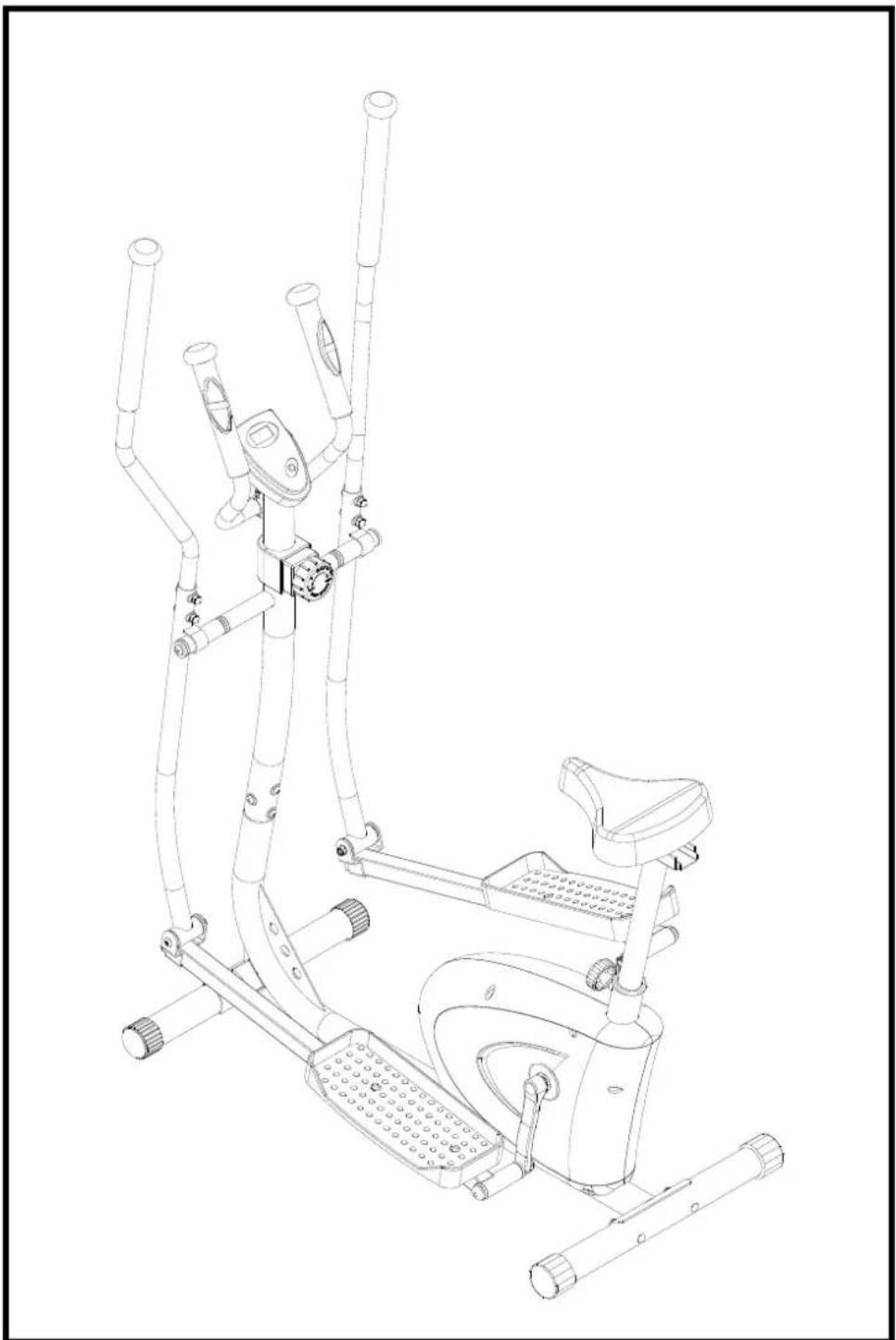
2 IN 1 MAGNETIC ELLIPTICAL STRIDER
natural_image
Line drawing of an exercise bike with adjustable arms and legs (no text or symbols)INDEX
Important Safety Information 1
Exploded-View Assembly Drawing 2
Parts List 3
Assembly Instruction 6
Exercise Instructions 9
Exercise Computer 11
Exercise Notes 13
Important Safety Information
Please keep this manual in a safe place for easy reference.
- It is important to read this entire manual before assembling and using the equipment.
Safe and effective use can only be achieved if the equipment is assembled, maintained and used properly. It is your responsibility to ensure that all users of the equipment are informed of all warnings and precautions.
-
Before starting any exercise program you should consult your doctor to determine if you have any medical or physical conditions that could put your health and safety at risk, or prevent you from using the equipment properly. Your doctor's advice is essential if you are taking medication that affects your heart rate, blood pressure or cholesterol level.
-
Be aware of your body's signals. Incorrect or excessive exercise can damage your health. Stop exercising if you experience any of the following symptoms: pain, tightness in your chest, irregular heartbeat, extreme shortness of breath, lightheadedness, dizziness or feelings of nausea. If you do experience any of these conditions you should consult your doctor before continuing with your exercise program.
-
Keep children and pets away from the equipment. The equipment is designed for adult use only.
-
Use the equipment on a solid, flat level surface with a protective cover for your floor or carpet. To ensure safety, the equipment should have at least 0.5 meters of free space all around it.
-
Before using the equipment, check that the nuts and bolts are securely tightened.
-
The safety of the equipment can only be maintained if it is regularly examined for damage and/or wear and tear.
-
Warning the equipment must be installed on a stable base and properly leveled floor. Always use the equipment as indicated. If you find any defective components while assembling or checking the equipment, or if you hear any unusual noises coming from the equipment during use, stop immediately. Do not use the equipment until the problem has been rectified.
-
Wear suitable clothing while using the equipment. Avoid wearing loose clothing that may get caught in the equipment or that may restrict or prevent movement.
-
The equipment has been tested and certified to EN957 under class H.C. Suitable for home use only. Maximum weight of user: 100kg. Braking ability is independent of speed.
-
The equipment is not suitable for therapeutic use.
-
Care must be taken when lifting or moving the equipment so as not to injure your back. Always use proper lifting techniques and/or seek assistance if necessary. Regular checking of the integrity of guards and safety devices.
-
Parents and those in charge of children should be aware of their responsibility around this equipment. The natural play instinct and fondness for experimenting of children can lead to situations and use of the training equipment for which it is not intended.
-
If children are allowed to use the equipment their mental and physical development and above all their temperament should be taken in to account. They should be supervised and instructed to the correct use of the equipment. The equipment is under no circumstances suitable as a child's toy.
-
All moveable accessories (eg. pedal, handlebar, saddle....etc.) require weekly maintenance. Check them before use every time. If anything broken or loose, please fix them immediately. You may continue using bike after they return to good conditions.
-
If you experience any problems or require assistance, please contact our customer services on:
Address: Morley Carr Road, Low Moor, BD12 0BR Bradford, U.K.
Service line: 01274 693888
*This is only available for UK resident*
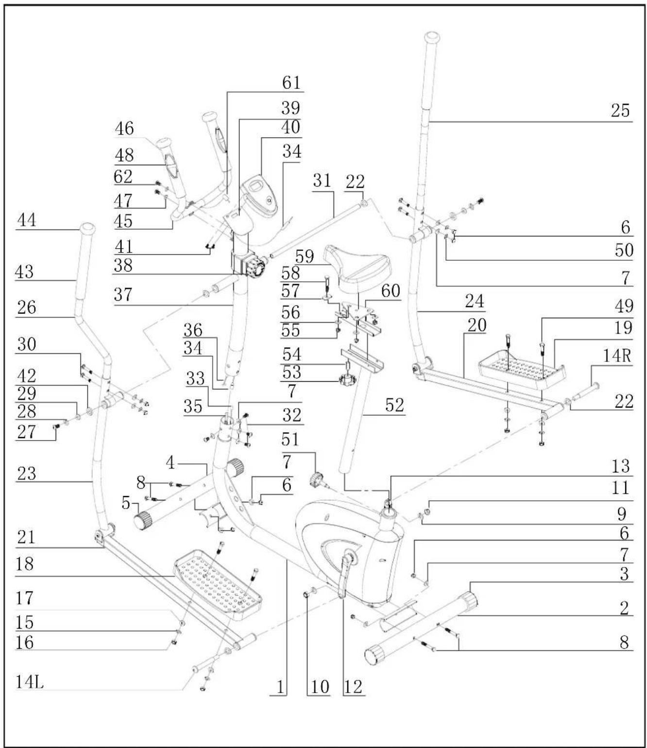
EXPLODED-VIEW ASSEMBLY DRAWING
text_image
46 48 62 47 45 41 38 37 36 34 33 35 4 8 5 21 18 17 15 16 14L 61 39 40 34 31 22 59 58 57 56 55 54 53 7 32 51 7 6 1 10 12 25 6 50 7 24 20 49 19 14R 22 13 11 9 6 7 3 2 8| PARTS LIST | |||||
| PART NO. | DESCRIPTION QTY | PART NO. | DESCRIPTION QTY | ||
| 1. | Main Frame | 1 | 32. | Carriage Bolt (M8 x15) | 4 |
| 2. | Rear Stabilizer | 1 | 33. | Lower Wire | 1 |
| 3. | Rear End Cap | 2 | 34. | Upper Wire | 1 |
| 4. | Front Stabilizer | 1 | 35. | Lower Cable | 1 |
| 5. | Front End Cap | 2 | 36. | Upper Cable | 1 |
| 6. | Domed Nut (M8) | 8 | 37. | Front post | 1 |
| 7. | Curved Washer (∅8) | 12 | 38. | Tension Knob | 1 |
| 8. | Bolt (M8 x 60) | 4 | 39. | Computer Holder | 1 |
| 9. | Spring Washer (1/2") | 2 | 40. | Computer | 1 |
| 10. | Safety Nut (1/2") | 1 | 41. | Fix Screw | 2 |
| 11. | Safety Nut (1/2") | 1 | 42. | Washer(∅28 x 5) | 2 |
| 12. | Crank (Left) | 1 | 43. | Foam Grip | 2 |
| 13. | Crank (right) | 1 | 44. | Handle bar end cap | 4 |
| 14R. | Pedal Hinge Bolt (R) (1/2") | 1 | 45. | Handle bar | 1 |
| 14L. | Pedal Hinge Bolt (L) (1/2") | 1 | 46. | Foam Grip | 2 |
| 15. | Spring Washer (∅10) | 4 | 47. | Washer (∅8) | 2 |
| 16. | Nut ( M10) | 4 | 48. | Pulse sensor | 2 |
| 17. | Washer (∅10) | 4 | 49. | Bolt (M10 x 50) | 4 |
| 18. | Pedal (Left) | 1 | 50. | Spring washer (∅ 8) | 4 |
| 19. | Pedal ( Right) | 1 | 51. | Adjustment knob | 1 |
| 20. | Pedal tubing ( Right) | 1 | 52. | Seat Post | 1 |
| 21. | Pedal Tubing (Left) | 1 | 53. | Adjustment seat knob | 1 |
| 22. | Wavy Washer (∅26x∅17.8x0.3) | 4 | 54. | Bushing | 1 |
| 23. | Left Handlebar | 1 | 55. | Nylon nut (M8) | 3 |
| 24. | Right Handlebar | 1 | 56. | Flat Washer (∅ 8) | 3 |
| 25. | Right Fixed Handlebar | 1 | 57. | Pad | 1 |
| 26. | Left Fixed Handlebar | 1 | 58. | Carriage Bolt (M8 x45) | 1 |
| 27. | Allen key Bolt (M10 x 25) | 2 | 59. | Seat | 1 |
| 28. | Spring Washer (∅10) | 2 | 60. | Horizontal tube | 1 |
| 29. | Washer (∅10 ) | 2 | 61. | Pulse sensor wire | 1 |
| 30. | Carriage Bolt (M8 x 40) | 4 | 62. | Carriage Bolt (M8 x25) | 2 |
| 31. | Connecting Shaft | 1 | |||
| Parts Description | Quantity | Parts Description | Quantity |
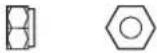 | NO.10.11X2PC |  | NO.62X 2 PCS |
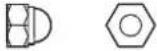 | NO.6 X8PCS | 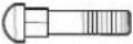 | NO.30X4 PCS |
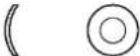 | NO.7 X 8PCS | 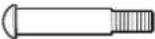 | NO.14(L)X1 PCSNO.14(R)X1 PCS |
 | NO.29 X 2PCS | 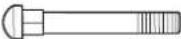 | NO.8X4 PCS |
 | NO.47 X 2PCS | 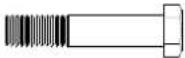 | NO.49X4 PCS |
 | NO.17 X 4PCS |  | NO.32X4 PCS |
 | NO.16 X 4PCS |  | NO.27X2 PCS |
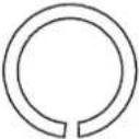 | NO.9 X 2PCS | [5TH] | NO.41X2 PCS |
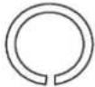 | NO.15 X 4PCS | 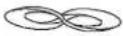 | NO.22X4 PCS |
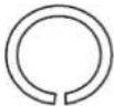 | NO.28 X 2PCS | 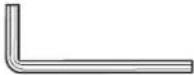 | 1 PCS |
 | [HHHS] | 2 PCS | |
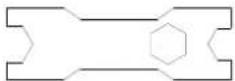
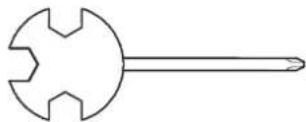 |  #31 *1 #31 *1 | ||
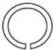 | NO.50X4PCS |  | NO.56X 3PCS |
 | NO.42X2PCS | 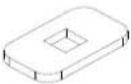 | NO.57X 1PCS |
| NO.54X1PCS | 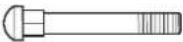 | NO.58X 1PCS | |
| [H208] [420H] | NO.55X3PCS | ||
ASSEMBLY INSTRUCTIONS
STEP 1
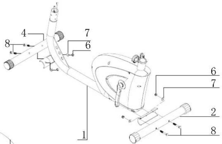
Attach the Rear and Front stabilizer (2 and 4) to the main frame (1) using four sets of M8 domed nuts (6), ∅8 Washers (7) and M8 X 60 Bolts (8).
text_image
1 2 3 4 5 6 7 8
text_image
38 37 36 34 35 33 32 7 1 36 34 33 35STEP2
Take the Front Post (37), assemble to the Main Frame (1), first connect the Lower Sensor Wire (33) to the Upper Sensor Wire (34), and attach the Upper Tension Cable (36) to the Lower Tension Hook (35), (as shown as the figure), Finally, put Circle cap (50) into Main Frame (1)
Attach the Front Post (37) to the Main Frame (1) using four sets of Curved Washer (∅8) and Carriage Bolt (M8 x15).
text_image
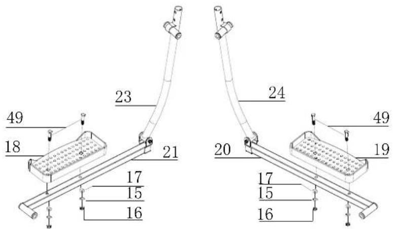
49 18 23 21 17 15 16 20 24 49 19 17 15 16STEP 3
Attach the left and right Pedal (19) & (18) to the Pedal Tubing (20) & (21), using M10*50 Bolt (49), ∅8 washers (17), ∅8 Spring Washer (15) and M8 Nut (16).
text_image
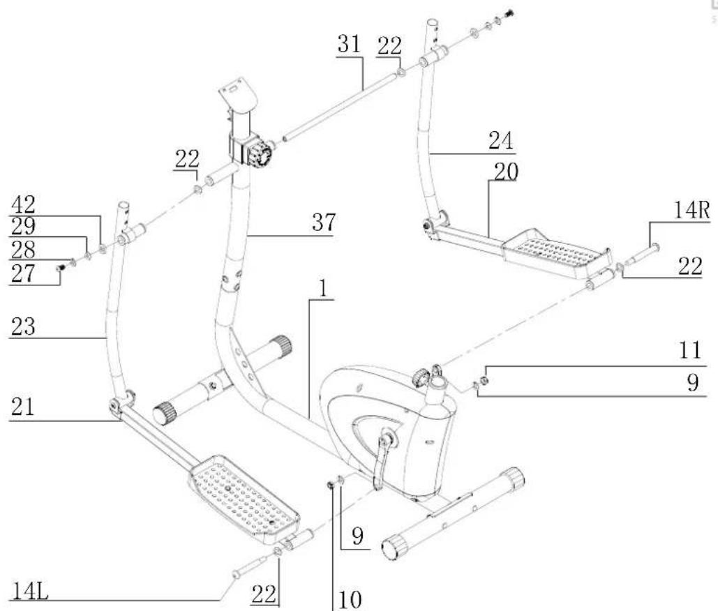
42 29 28 27 23 21 14L 22 31 22 22 37 1 9 10 24 20 14R 22 11 9STEP 4
Fixing the left and right pedal assembly to the Front Post (37) inset the connecting shaft (31) and then fit with ∅26x∅17.8 Wavy Washer (22), ∅25 Washer (42), ∅28x ∅8 Spring washer (29), ∅8 washer (28) and M8x 20 Fixing Bolt (27).
Then connect the Pedal Frame (L&R) to the Crank using 1/2" Hinge Bolt (14L and 14R), ∅26x ∅17.8 Wavy Washer (22), 1/2" Spring Washer (9), and 1/2" Safety Nut (10&11).
text_image
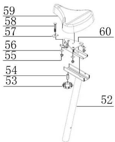
59 58 57 56 55 54 53 60 52STEP 5
Fix the Seat (pt.59) to the Horizontal tube (pt.60) by using the three sets of Flat Washers (pt.56) and M8 Nylon Nuts (pt.55) located under the seat.
Fix the Horizontal tube (pt.60) to the Seat post (pt.52) by using M8 x45 Carriage Bolt (58), Pad (57), Bushing (54) and Adjustment seat knob (53).
text_image
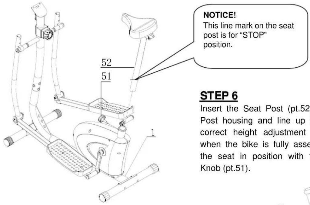
NOTICE! This line mark on the seat post is for "STOP" position. 52 51 STEP 6 Insert the Seat Post (pt.52) Post housing and line up correct height adjustment when the bike is fully asse the seat in position with t Knob (pt.51).NOTICE!
This line mark on the seat post is for "STOP" position.
STEP 6
Insert the Seat Post (pt.52) into the Seat Post housing and line up the holes (The correct height adjustment can be made when the bike is fully assembled) Secure the seat in position with the Adjustment Knob (pt.51).
STEP 7
Fit the Front Handlebar (45) to the Front Post clamp as shown, fix with two sets of ∅8 washer (47) and M7 x 25 Carriage Bolt (62).

text_image
62 47 45 37STEP 8
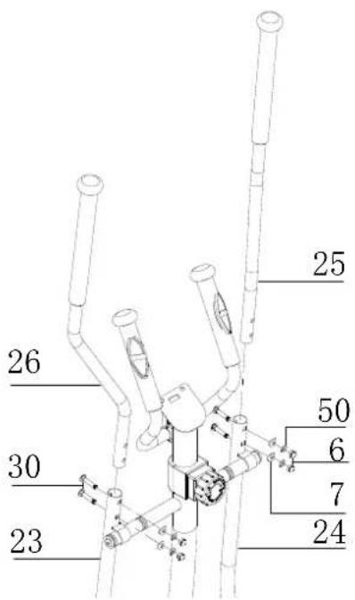
Slide the Right Fixed Handlebar (25) and Left Fixed Handlebar (26) into the Right Handlebar (24) and Left Handlebar (23), and then fix with four sets of M8x45 Carriage bolts (30), ∅8 Curved Washer (7), ∅8 Spring Washer (50), and M8 Domed Nut (6).
text_image
25 26 30 23 50 6 7 24STEP 9
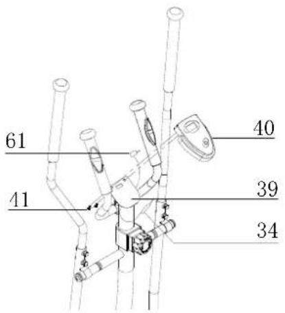
Slide the Computer (40) down to the Computer holder (39) situated at the top of Front post (37) and fix using two fixing screws (41). Plug the Sensor Wires (34) and Pulse sensor wire (61) into the back of the Computer (40) as shown as the figure.
text_image
61 40 41 39 34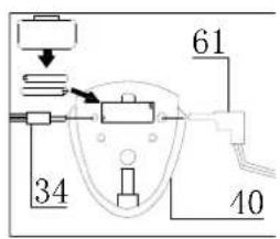
text_image
34 61 10TENSION CONTROLL
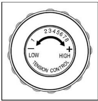
Turn the tension knob by clockwise to increase the resistance. To decrease the resistance, turn the knob by anti-clockwise.
text_image
1 2 3 4 5 6 7 8 - LOW TENSION CONTROL + HIGHEXERCISE INSTRUCTIONS
Using your 2 IN 1 MAGNETIC ELLIPTICAL STRIDER will provide you with several benefits. It will improve your physical fitness, tone your muscles and, in conjunction with a calorie-controlled diet, help you lose weight.
1. The Warm Up Phase
This stage helps get the blood flowing around the body and the muscles working properly. It will also reduce the risk of cramp and muscle injury. It is advisable to do a few stretching exercises as shown below. Each stretch should be held for approximately 30 seconds, do not force or jerk your muscles into a stretch - if it hurts, STOP.
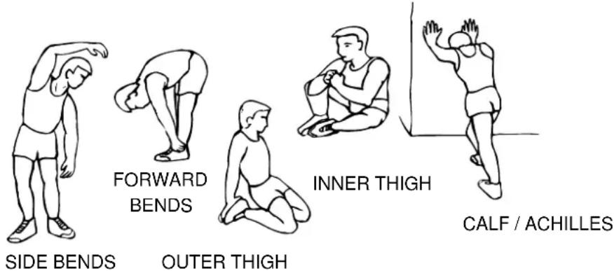
text_image
FORWARD BENDS INNER THIGH SIDE BENDS OUTER THIGH CALF / ACHILLES2. The Exercise Phase
This is the stage where you put the effort in. After regular use, the muscles in your legs will become more flexible. Work at your own pace and be sure to maintain a steady tempo throughout. The rate of work should be sufficient to raise your heartbeat into the target zone shown on the graph below.
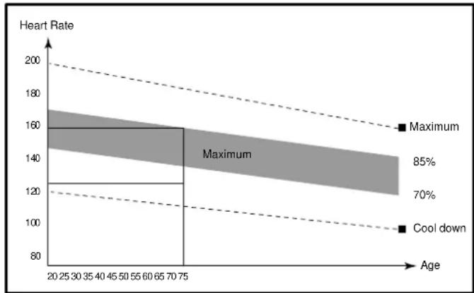
line
| Age Range | Heart Rate | | --------- | ---------- | | 20-25 | 160 | | 25-30 | 160 | | 30-35 | 160 | | 35-40 | 160 | | 40-45 | 160 | | 45-50 | 160 | | 50-55 | 160 | | 55-60 | 160 | | 60-65 | 160 | | 65-70 | 160 | | 70-75 | 160 |This stage should last for a minimum of 12 minutes though most people start at about 15-20 minutes
3. The Cool Down Phase
This stage is to let your Cardio-vascular System and muscles wind down. This is a repeat of the warm up exercise e.g. reduce your tempo, continue for approximately 5 minutes. The stretching exercises should now be repeated, again remembering not to force or jerk your muscles into the stretch.
As you get fitter you may need to train longer and harder. It is advisable to train at least three times a week, and if possible space your workouts evenly throughout the week.
MUSCLE TONING
To tone muscle while on your 2 IN 1 MAGNETIC ELLIPTICAL STRIDER you will need to have the resistance set quite high. This will put more strain on your leg muscles and may mean you cannot train for as long as you would like. If you are also trying to improve your fitness you need to alter your training program. You should train as normal during the warm up and cool down phases, but towards the end of the exercise phase you should increase resistance making your legs work harder. You will have to reduce your speed to keep your heart rate in the target zone.
WEIGHT LOSS
The important factor here is the amount of effort you put in. The harder and longer you work the more calories you will burn. Effectively this is the same as if you were training to improve your fitness, the difference is the goal.
EXERCISE COMPUTER
SPECIFICATIONS:
TIME....00:00 -99:59
SPEED....0.0-99.9KM/H or ML/H
DISTANCE....0.00-999.9KM or ML
ODOMETER * (option)....0-9999KM or ML
PULSE * (option)......40-240BPM
CALORIES (CAL)....0-9999CAL
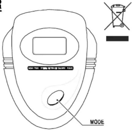
text_image
SCAN TREE MODE CAN TREE MODEKEY FUNCTIONS:
MODE: This key lets you to select and lock on to a particular function you want.
OPERATUION PROCEDURES:
1. AUTO ON/OFF:
※ The system turns on when any key is pressed or when it receives an signal input from the speed sensor.
※ The system turns off automatically when the sensor has no signal input or no key are pressed for approximately 4 minutes.
2. RESET:
The unit can be reset by either changing the battery or pressing the mode key for 3 seconds.
3. MODE:
To choose the SCAN or LOCK if you do not want the scan mode, press the MODE key when the pointer on the function you want which begins blinking.
4. FUNCTIONS:
TIME: Press the MODE key until the pointer advance to TIME. The total working time will be shown.
SPEED: Press the MODE key until the pointer advance to SPEED. The total current speed will be shown.
DISTANCE: Press the MODE key until the pointer advance to DISTANCE. The distance of each Workout will be displayed.
ODOMETER(Option): Press the MODE key until the pointer advance to ODO METER. The total accumulated distance will be shown.
PULSE: Press the MODE key until pointer advance to PULSE. User's current heart rate will be displayed in beats per minute. Place the palms of your hands on both of the Contact pads (or put ear-clip to ear), and wait for 30 seconds for the most accurate reading.
CALORIES: Press the MODE key until the pointer advance to CALORIES. The calories burned will be displayed.
SCAN: Automatic display of the following functions in the order shown: TIME----SPEED---- DISTANCE-- -- PULSE ---- CALORIES (repeat).
BATTERY
- This monitor uses one or two (if have PULSE function) battery. If improper display on monitor, please reinstall the batteries to have a good result.
TROUBLE SHOOTING:
- Change the battery. To change the computer battery, please slide the computer from the computer holder, remove the battery cover on the back of the computer console, and remove the batteries. Replace with AA batteries. Finally put the cover back on the console, and slide the computer back on the computer holder.
- Computer not working correctly. If your computer is not working correctly, please check whether the lower sensor wire is connected to the upper sensor wire, and make sure the upper sensor wire is plugged into the computer. When you have checked the above, and the computer still not working, then please make sure the batteries are installed correctly in the computer and that the batteries are still working.
- No resistance. If there is no tension resistance on the bike, please make sure the upper tension cable is connected to the lower tension cable.
MAINTENANCE
- Before using the bike, always make sure all bolts/nuts are fully tightened.
- A spent battery is hazardous waste, please dispose of it correctly, and do not throw it in the trash.
- When eventually you want to scrap the machine, you should remove the batteries from the computer, and dispose separately as hazardous waste.
BATTERY DISPOSAL
- A spent battery is hazardous waste - please dispose of it correctly and do not throw it in the trash.
- When you eventually want to scrap the machine, you should remove the batteries from the computer, and dispose of them separately as hazardous waste.
- Keep batteries out of the reach of small children. Batteries are extremely dangerous when swallowed. If a battery has been swallowed, seek immediate medical treatment.
natural_image
Illustration of a pencil writing on a notepad (no text or symbols present)EXERCISE NOTES
Use this space to record your own exercise routine results.

text_image
BODY® SCULPTURESINCE 1965