EFX 811 - Fitness Equipment Precor - Free user manual and instructions
Find the device manual for free EFX 811 Precor in PDF.


User questions about EFX 811 Precor
0 question about this device. Answer the ones you know or ask your own.
Ask a new question about this device
Download the instructions for your Fitness Equipment in PDF format for free! Find your manual EFX 811 - Precor and take your electronic device back in hand. On this page are published all the documents necessary for the use of your device. EFX 811 by Precor.
USER MANUAL EFX 811 Precor
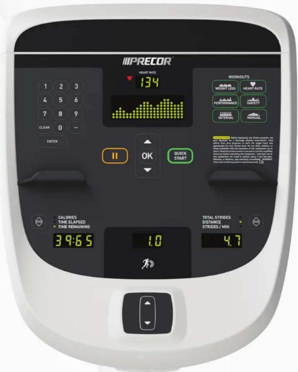
Operating and Maintaining the P10 Console
text_image
IMPRECOR HEART RATE 134 WORKOUTS WEIGHT LOSS HEART RATE PERFORMANCE VARIETY INTERVAL MANUAL ORDER: before beginning any Fitness program, we need to prepare for a meaningful Efficient Amperization tool. Note from your position to break the target Forest line. We not alter AMRPA on these exercises with the exception of this equipment. For example, find the product item's manual or complete a qualified instrument before operating this equipment. Equipment set of this equipment can result in serious injury. If you feel pain, reference, or absence, stay monitoring immediately, included. Heart rate is monthly by system to help the exercise. CALORIES TIME ELAPSED TIME REMAINING 39:65 1.0 TOTAL STRIDES DISTANCE STRIDES / MIN 4.7Operating and Maintaining the P10 Console
Edition Information
OPERATING AND MAINTAINING THE P10 CONSOLE
Copyright © June 2014 Precor Incorporated. All rights reserved. Specifications subject to change without notice.
Trademark Note
Precor, AMT, EFX, and Preva are registered trademarks of Precor Incorporated. Other names in this document may be the trademarks or registered trademarks of their respective owners.
Intellectual Property Notice
All rights, title, and interests in and to the software of the Preva Business Suite, the accompanying printed materials, any copies of such software, and all data collected via the Preva Business Suite, are exclusively owned by Precor or its suppliers, as the case may be.
Precor is widely recognized for its innovative, award-winning designs of exercise equipment. Precor aggressively seeks U.S. and foreign patents for both the mechanical construction and the visual aspects of its product design. Any party contemplating the use of Precor product designs is hereby forewarned that Precor considers the unauthorized appropriation of its proprietary rights to be a very serious matter. Precor will vigorously pursue all unauthorized appropriation of its proprietary rights.
Precor Incorporated 20031 142nd Ave NE, P.O. Box 7202 Woodinville, WA 98072-4002 1-800-347-4404
http://www.precor.com
Important Safety Instructions
Important: Save these instructions for future reference.
Read all instructions in the documentation provided with your exercise equipment, including all assembly guides, user guides, and owner's manuals, before installation of this device.
Note: This product is intended for commercial use.
The display apparatus (hereinafter referred to as the console) is intended to be shipped with new Precor exercise equipment (hereinafter referred to as the base unit). It is not packaged for individual sale.
WARNING
To prevent injury, the console must be attached securely to the base unit following all assembly and installation instructions shipped with the base unit. The console is intended to be connected to AC mains power through the furnished power supply ONLY. It should be powered on only when installed as described in the assembly and installation instructions shipped with the base unit. The console is intended for use only with Precor fitness equipment, not as a standalone device.
Safety Precautions
Always follow basic safety precautions when using this equipment to reduce the chance of injury, fire, or damage.
Other sections in this manual provide more details of safety features. Be sure to read these sections and observe all safety notices. These precautions include the following:
- Read all instructions in this guide before installing and using the equipment and follow any labels on the equipment.
- Make sure all users see a physician for a complete physical examination before they begin any fitness program, particularly if they have high blood pressure, high cholesterol or heart disease; have a family history of any of the preceding conditions; are over the age of 45; smoke; are obese; have not exercised regularly in the past year; or are taking any medication.
- Do not allow children, or people unfamiliar with the operation of this equipment, on or near it. Do not leave children unsupervised around the equipment.
- Make sure all users wear proper exercise clothing and shoes for their workouts and avoid loose or dangling clothing. Users should not wear shoes with heels or leather soles, and they should check the soles of their shoes to remove any dirt and embedded stones. They should also tie long hair back.
- Never leave the equipment unattended when it is plugged in. Unplug the equipment from its power source when it is not in use, before cleaning it, and before providing authorized service.
Note: The optional power adapter is considered a power source for self-powered equipment. - Use the power adapter provided with the equipment. Plug the power adapter into an appropriate, grounded power outlet as marked on the equipment.
- Care should be taken when mounting or dismounting the equipment.
- For Treadmills: Do not use typing or web surfing features while walking at speeds that exceed a slow and relaxed leisurely pace. Always stabilize yourself by holding a stationary handle bar while using typing or web surfing features.
- For AMT and EFX: Always stabilize yourself by holding a stationary handle bar while using typing or web surfing features.
- Read, understand, and test the emergency stop procedures before use.
- Keep the power cord or optional power adapter and plug away from heated surfaces.
- Route power cables so that they are not walked on, pinched, or damaged by items placed upon or against them, including the equipment itself.
- Ensure the equipment has adequate ventilation. Do not place anything on top of or over the equipment. Do not use on a cushioned surface that could block the ventilation opening.
- Assemble and operate the equipment on a solid, level surface.
- SPACING—The below minimum spacing recommendations are based on a combination of the ASTM (U.S.) voluntary standards and EN (European) regulations as of October 1, 2012, for access, passage around, and emergency dismount:
- Treadmills—a minimum of 0.5 m (19.7 in.) on each side of the treadmill and 2 m (78 in.) behind the machine.
- Cardio equipment other than treadmills—a minimum of 0.5 m (19.7 in.) on at least one side, and 0.5 m (19.7 in.) behind or in front the machine.
Careful consideration should be given to the requirements of the Americans with Disabilities Act (ADA), US Code 28 CFR (see Section 305). ASTM
standards are voluntary and may not reflect current industry standards. The actual area for access, passage around, and emergency dismount is the responsibility of the facility. The facility should consider the total space requirements for training on each unit, voluntary and industry standards, and any local, state, and federal regulations. Standards and regulations are subject to change at any time.
Important: These spacing recommendations should be used when positioning equipment away from sources of heat, such as radiators, heat registers, and stoves. Avoid temperature extremes.
- Keep equipment away from water and moisture. Avoid dropping anything on or spilling anything inside the equipment to prevent electric shock or damage to the electronics.
- When using the treadmill, always attach the safety clip to your clothing before beginning your workout. Failure to use the safety clip may pose a greater risk of injury in the event of a fall.
- Keep in mind that heart rate monitors are not medical devices. Various factors, including the user's movement, may affect the accuracy of the heart rate readings. The heart rate monitors are intended only as exercise aids in determining heart rate trends in general.
- Do not operate electrically powered equipment in damp or wet locations.
-
Never operate this equipment if it has a damaged cord or plug, if it is not working properly, or if it has been dropped, damaged, or exposed to water. Call for service immediately if any of these conditions exist.
-
Maintain the equipment to keep it in good working condition, as described in the Maintenance section of the owner's manual. Inspect the equipment for incorrect, worn, or loose components, and then correct, replace or tighten prior to use.
- If you plan to move the equipment, obtain help and use proper lifting techniques.
- Equipment Weight Restrictions: Do not use the treadmill if you weigh more than 400 pounds (180 kg). If you weigh more than 350 pounds (160 kg), do not run on the treadmill. For all other fitness equipment, the weight limit is 350 pounds (160 kg).
- Use the equipment only for its intended purpose as described in this manual. Do not use accessory attachments that are not recommended by Precor. Such attachments may cause injuries.
- Do not operate the equipment where aerosol (spray) products are being used or where oxygen is being administered.
- Do not use outdoors.
- Do not attempt to service the equipment yourself, except to follow the maintenance instructions in the owner's manual.
- Never drop or insert objects into any opening. Keep hands away from moving parts.
- Do not set anything on the stationary handrails, handlebars, control console, or covers. Place liquids, magazines, and books in the appropriate receptacles.
- Do not lean on or pull on the console at any time.

CAUTION: DO NOT remove the cover, or you may risk injury due to electric shock. Read the assembly and maintenance guide before operating. There are no user-serviceable parts inside. Contact Customer Support if the equipment needs servicing. For use with single phase AC power only.
Hazardous Materials and Proper Disposal
The batteries within self-powered equipment contain materials that are considered hazardous to the environment. Federal law requires proper disposal of these batteries.
If you plan to dispose of your equipment, contact Precor Commercial Products Customer Support for information regarding battery removal. Refer to Obtaining Service.
Product Recycling and Disposal
This equipment must be recycled or discarded according to applicable local and national regulations.
Product labels, in accordance with European Directive 2002/96/EC concerning waste electrical and electronic equipment (WEEE), determine the framework for the return and recycling of used equipment as applicable throughout the European Union. The WEEE label indicates that the product is not to be thrown away, but rather reclaimed upon end of life per this Directive.
In accordance with the European WEEE Directive, electrical and electronic equipment (EEE) is to be collected separately and to be reused, recycled, or recovered at end of life. Users of EEE with the WEEE label per Annex IV of the WEEE Directive must not dispose of end of life EEE as unsorted municipal waste, but use the collection framework available to customers for the return, recycling, and recovery of WEEE. Customer participation is important to minimize any potential effects of EEE on the environment and human health due to the potential presence of hazardous substances in EEE. For proper collection and treatment, refer to Obtaining Service.
Regulatory Notices for Cardiovascular Exercise Equipment
The regulatory information in this section applies to the exercise equipment and its control console.
Safety Approvals for Cardiovascular Equipment
Precor equipment has been tested and found to comply with the following applicable safety standards.
Cardiovascular Type Equipment:
• CAN/CSA, IEC, EN 60335-1 (Household and similar electrical appliances - Safety)
• EN 957 (Stationary training equipment, class S/B compliant equipment)
Radio Frequency Interference (RFI)
This Precor exercise equipment conforms to the following national standards defining acceptable limits for radio frequency interference (RFI).
Federal Communications Commission, Part 15
This equipment has been tested and found to comply with the limits for a Class A digital device, pursuant to Part 15 of the FCC Rules. These limits are designed to provide reasonable protection against harmful interference in a commercial installation. The equipment generates, uses, and can radiate radio frequency energy and, if not installed and used in accordance with the owner's manual instructions, can cause harmful interference to radio communications.
Operation is subject to the following two conditions: (1) this device may not cause harmful interference, and (2) this device must accept any interference received, including interference that may cause undesired operation.
WARNING
Per FCC rules, changes or modifications not expressly approved by the manufacturer could void the user's authority to operate the equipment.
Industry Canada
This device complies with RSS-210:2007 of the Spectrum Management & Telecommunications Radio Standards Specification. Operation is subject to the following two conditions: (1) this device may not cause harmful interference, and (2) this device must accept any interference received, including interference that may cause undesired operation.
This Class A digital apparatus complies with Canadian ICES-003.
European Applications
CE compliance is claimed to the following directives:
• 2004/108/EC EMC Directive
• 2006/95/EC LVD Directive
• 2002/95/EC RoHS Directive
Directive compliance has been verified to the following standards:
• EN 55022
• EN 55024
- EN 60335-1
• EN 60065 (P80 and PVS)
Electrical Recommendations: 120 V and 240 V Treadmills
Note: This is a recommendation only. NEC (National Electric Code) guidelines or local region electric codes must be followed.
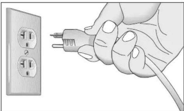
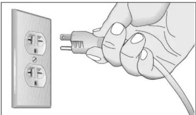
You should have received a power cable that meets your local electrical code requirements along with the equipment. Precor treadmills must be connected to a 20 amp individual branch circuit that can be shared only with one PVS. If you need additional help with the power connections contact your Precor authorized dealer.
Important: An individual branch circuit provides a hot conductor and neutral conductor to a receptacle. The conductors must not be looped, "daisy-chained", or connected to any other conductors. The circuit must be grounded according to NEC guidelines or local region electric codes.
natural_image
Illustration of hands connecting a power outlet to a plug, showing electrical wiring (no text or symbols)Figure 1: North American 120-volt, 20-amp power receptacle
natural_image
Illustration of a hand inserting a plug into an electrical outlet (no text or symbols)Figure 2: North American 240-volt, 20-amp power receptacle
Electrical Recommendations: All Equipment Excluding Treadmills
Note: This is a recommendation only. NEC (National Electric Code) guidelines or local region electric codes must be followed.
For equipment fitted with a P80 console or Personal Viewing System (PVS) screen a separate power connection is required. For a 20 amp branch circuit up to 10 screens can be connected. If the branch circuit has any other devices plugged into the circuit, then the number of screens must be reduced by the wattage of the other devices.
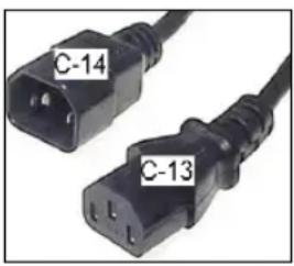
Note: The typical splitter power cords that have IEC-320 C13 and C14 plugs have a recommended maximum capacity of five screens.
text_image
C-14 C-13Figure 3: IEC-320 C13 and C14 plugs
Obtaining Service
Do not attempt to service the equipment except for maintenance tasks. If any items are missing, contact your dealer. For more information regarding customer support numbers or a list of Precor authorized service centers, visit the Precor web site at http://www.precor.com.
Table of Contents
Important Safety Instructions .... 3
Safety Precautions....4
Hazardous Materials and Proper Disposal 8
Product Recycling and Disposal 8
Regulatory Notices for Cardiovascular Exercise Equipment....9
Electrical Recommendations: 120 V and 240 V Treadmills .... 11
Electrical Recommendations: All Equipment Excluding Treadmills....12
Obtaining Service....12
Getting Started....15
Activating the Console for Self-Powered Equipment ....15
Identifying Parts of the Console....17
Setting Up the Console 19
System Settings....19
Club Parameters....21
Viewing the Informational Displays 25
User ID Entry with CSAFE Equipment....30
Introducing Users to the P10 Console....31
Using the Touch Heart Rate Feature....31
Using a Chest Strap Transmitter 33
Using the Treadmill Safety Clip 34
Treadmill Auto Stop ^TM (Automatic Stop) Function......36
Starting a Workout 37
Starting a Preset Programmed Workout 38
Pausing and Resuming an Exercise Session.... 38
Ending a Session....39
Workouts....41
Maintenance....49
Cleaning the Console and Display....50
Checking and Resetting the Active Status Light (Treadmill Only)....51
Changing the Belt (AMT Only) 54
Getting Started
The P10 console offers administrators the ability to set default values that meet their specific needs. These values include items like language, units of measure, and setting a maximum allowed workout time for each piece of equipment.
Activating the Console for Self-Powered Equipment
Precor equipment is either self-powered or externally powered using an optional power adapter. Self-powered equipment requires the user exercise to initialize the console. This section provides more detail about powering equipment.
Activating the Console for Self-Powered Equipment
On self-powered equipment, when a user starts exercising, the console initializes and displays the Welcome banner. A minimum rate of motion must be maintained for the Welcome banner to appear. The words PEDAL FASTER (or the equivalent message depending on the equipment type) appear in the display when the rate of motion drops below the minimum requirements.
The equipment saves its battery charge by moving into a shutdown mode. If the user does not maintain the minimum rate of motion, a 30-second shutdown process begins.
In this mode, the console displays a countdown indicator and ignores all keypresses. If no movement is detected or the rate of motion remains below the minimum, the indicator changes as the countdown continues.
Note: The user can resume exercising before the countdown period elapses and the workout will continue from the point at which it was paused.
Optional Use of the Power Adapter
An optional AC power adapter provides sustained power to the equipment. This adapter allows you to change settings without having to pedal the equipment. To purchase the power adapter, contact your dealer.
If you purchase the optional power adapter, you must also purchase the internal cable kit. The kit supplies the cable, bracket, and fasteners that connect the power adapter to the lower electronics board.
CAUTION: The internal cable kit must be installed by authorized service personnel. Do not attempt installation on your own as you could void the Precor Limited Warranty. For more information, refer to Obtaining Service.
Important: If this equipment includes a P80 console, the optional power adapter and the internal cable kit must still be installed to provide continuous power to the base unit and support its internal battery.
Once the internal cable kit is installed, you can plug the optional power adapter into the equipment. Plug the opposite end into the appropriate power source for your equipment (120 V or 240 V). Review the safety instructions found at the beginning of this manual before using the power adapter.
CAUTION: When the optional power adapter is in use, make sure that the power supply cord does not create a safety hazard. Keep it out of the way of traffic and moving parts. If the power supply cord or power conversion module is damaged, it must be replaced.
The control console functions differently when the power adapter is connected. Because the power adapter provides a constant source of power, a user can pause for brief periods without initiating shutdown procedures. When the pause time limit expires and the user has not resumed exercising, the console returns to the Welcome screen. The default pause time is 30 seconds for all fitness equipment. Refer to the manual for your control console for instructions on setting or changing the pause time limit.
Identifying Parts of the Console
The following figure provides information about the console keys. The number and actions of the console keys may differ slightly depending on the type of equipment.
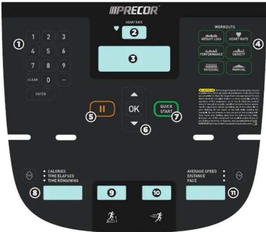
text_image
IMPRECOR HEART RATE 2 1 2 3 4 5 6 7 8 9 CLEAR 0 - ENTER WORKOUTS Weight Loss HEART RATE PERFORMANCE VARIETY INTERVAL MANUAL OFFICE Before beginning every time program, then used to prepare the following physical stimulus. Such actions have you been applied to the highest heart rate experience for your health. We will allow it to ensure that the exercise is a standard of use. For example, if you are working, you can start on the body wall, creating the heart rate. The exercise has been used as the working and keeping heart rate and shifting using the body wall and moving the heart rate. If you are working, you can start on the body wall, creating the heart rate and moving the heart rate. AVERAGE SPEED DISTANCE PACE CALORIES TIME ELAPSED TIME REMAINING 9 10 8 11Figure 4: P10 console keys
Table 1. Parts of the console
| Number | Name | Details |
| 1 | Number pad Enter | numerical information such as age, weight, and passwords. You can also enter and change channels using the number pad.PressClearto delete the numbers you entered.PressEnterto confirm your selection. |
| 2 | Heart Rate Displays your current heart rate. | |
| 3 | Lower Display Displays graphical information about your workout progress. | |
| 4 | Workouts Examples of workouts:ManualHeart RateIntervalWeight LossVarietyPerformance | • Manual• Heart Rate• Interval• Weight Loss• Variety• Performance |
| 5 | Pause Use to pause or end a workout session. | |
| 6 | OK and Up/Down arrows | Use to navigate options and settings. |
| 7 | Quick Start Press Quick Start to begin exercising. | |
| 8 | CaloriesTime ElapsedTime RemainingWatts (bike)Time (bike) | Use the ▲ or ▼ arrows to change what information is displayed. |
| 9 | Incline or Crossramp | Available on treadmill and EFX (dual). |
| 10 | Speed or Resistance | Available on AMT, bike, treadmill, EFX (single), and EFX (dual). |
| 11 | Average Speed (treadmill)Speed (bike)Pace (treadmill)Distance (all equipment)RPM (bike)Cals/Min (AMT)Strides/Min (AMT, EFX)Total Strides (EFX) | Use the ▲ or ▼ arrows to change what information is displayed. |
Setting Up the Console
Use the System mode to configure settings in ways that benefit your users and your facility. The System menu is visible only to administrators and registered service technicians. Changes made to these settings are saved to the fitness equipment.
The System Settings categories are:
- Club Parameters
• Informational Display
System Settings
System Setting features remain hidden from club patrons and can only be accessed using special keypresses. To view the System Settings, the equipment must be in the Welcome state. The equipment is in the Welcome state when it is on, but not actually in use. This means that there is no exercise session, data entry, or diagnostic operation in progress.
When the equipment is in the Welcome state:
- SELECT A WORKOUT OR PRESS QUICKSTART TO BEGIN scrolls in the text display.
- On the treadmill, the belt is not moving and the lift motor is off.
Note: On self-powered equipment, the console initializes when you begin working out. You must maintain a minimum rate of motion for the Welcome banner to appear.
The changes made in System Setting modes become the default settings when the display resets to the Welcome banner.
CAUTION: If you change the Unit of Measure display on the treadmill, check the speed setting to verify that it is correct.
To view the Club Settings:
- At the Welcome banner, press Pause.

- Press the following number keys in sequence to enter the password:
5651565
- Press OK.
The Set Club Parameters banner appears.
Table 2. Navigational keys for the system setting modes
| Key | Function |
| ▲ or ▼ | Navigates the settings menu |
| OK Selects a menu setting and confirms the changes made to the value setting | |
| CLEAR Returns to the previous menu level without saving changes | |
| PAUSE Exits the System Settings mode and returns to the Welcome banner | |
Club Parameters
Use the following information to customize the equipment for your setting.
Note: When you make changes to the club parameters, the new settings replace the factory default settings.
Safety Code (Treadmill only)
Value: Enabled or Disabled
(Default: Disabled)
When the equipment is shipped from the factory, the safety code protection feature is disabled. If you enable the safety code, your users will need to enter a four digit number to begin their exercise session and start the running belt. The code is 1234.
Select Language (All Equipment)
Value: English, Deutsch, Espanol, Francais, Netherlands, Portugues, Rucckijj, and Italiano
(Default: English)
Select your preferred language for the console display.
Note: Programming prompts are not affected by language selection. The prompts in this section continue to appear in English.
Select Units (All Equipment)
Value: U.S. or Metric
(Default: U.S.)
The equipment can display measurements in either Metric or U.S. Standard.
Important: If you change the Unit of Measure on a treadmill, be sure to check the speed setting to verify that it is correct.
Set Max Workout Time (All Equipment)
Value Range: 1 to 240 minutes
(Default: 60 minutes)
You can set a maximum workout time per session. Choose a time limit between 1 and 240 minutes, or select No Limit if you do not want to set a time limit. For example, if you set the time limit to 20 minutes, users can only enter a workout time between 1 and 20 minutes.
Set Max Pause Time (All Equipment)
Value Range: 1 to 120 seconds
(Default: 120 seconds)
This setting limits how long equipment remains in a paused banner during a workout before it resets.
Note: The optional power adapter must be connected on self-powered equipment to establish a definitive pause time limit. If the optional power adapter is not attached and the rate of motion drops below the minimum requirements, the equipment begins its shutdown, effectively eliminating pause mode.
Set Cool Down Time (All Equipment)
Value Range: 0 to 5 minutes
(Default: 5 minutes)
Select the maximum amount of time the equipment remains in the cool down mode. The cool down time is the period of time following the completion of a program when the user exercises at a reduced work rate.
Set Speed Limit (Treadmill only)
Value Range: Full speed range of equipment
(Default: Maximum speed)
This setting limits how fast the running belt moves and, consequently, the number of speed settings that are available to the user. Use it to set the maximum speed that a user can enter when using the equipment.
The speed is displayed in miles per hour (mph) or kilometers per hour (kph) depending upon the units of measure (U.S. Standard or Metric) selected earlier. The values range from 0.5 to 12 mph (0.8 to 20 kph).
Set Incline Limit (Treadmill only)
Value Range: Full grade range of equipment
(Default: Maximum grade possible)
Select the maximum percent incline that a user can enter when using the equipment. Values range from 0.0 to 15.0.
Hidden Programs (Treadmill only)
Value: Show Programs or Hide Programs
(Default: Hide Programs)
When this option is set to Show Programs, the user can select between the Track workout and the Fitness Test. Otherwise, only the Track workout is available.
Remote Speed Control (Treadmill only)
Value: Enable or Disable
(Default: Disable)
When this feature is enabled, the CSAFE SetSpeed command and the CSAFE SetGrade command are available if:
- The treadmill is in the CSAFE "InUse" state.
- The speed or grade values sent are within range.
Autostop Configure (Treadmill only)
Value: On or Off
(Default: On)
Set to On to bring the treadmill to a gradual stop when no user is on the equipment. This can occur if a user steps off the equipment during a workout and does not turn it off.
Set Crossramp Auto-level (EFX only)
Value Range: 0 to 20
(Default: 10)
Use this setting to choose a specific ramp incline so that the EFX automatically returns to that incline at the end of a workout session.
Set Resistance Range (Bike only)
Value Range: High, Medium, or Low
(Default: High)
You can set a low, medium, or high base resistance on the recumbent or upright bikes. There are 25 levels of resistance within each base setting, but the base setting affects the overall resistance range. The following ranges are available:
• High: Provides full resistance range.
- Medium: Provides approximately two thirds of the resistance that is available within the high group setting.
- Low: Provides approximately one third of the resistance that is available within the high group setting.
Viewing the Informational Displays
Information Display settings are values that provide you with information about the equipment. Types of information contained in this setting group include, an event (error) log, software and equipment serial numbers, and usage information.
To view the System settings:
- At the Welcome banner, press Pause.

- Press the following number keys in sequence to enter the password:
65
- Press OK.
Use the following table to set up customized Informational Display values.
Table 3. Informational Displays values
| Product | Value | Information provided |
| All ODOMETER Correlates | to the type of equipment and the standard of units, U.S. or Metric, selected in the programs.Treadmill and AMT: Displays the number of cumulative miles or kilometers logged to date. In addition, the AMT displays the number of vertical strides.EFX: Displays the number of total strides logged to date.Bike: Displays the number of total revolutions logged to date. | |
| AMT | BELT USAGE | Belt Stride Count:Tracks the number of strides on equipment.Stride Count Reset:Reset increases by one each time a reset is performed.Odometer at Last Reset:Records the odometer reading at the time the belt was changed. The equipment odometer continues to count forward after the belt change. |
| All HOUR METER Displays the number of hours that the equipment has been in use.Note:The equipment tracks the elapsed minutes, but the value that appears is truncated to the nearest full hour. | ||
| Treadmill | BELT RATING | Displays the condition of the treadmill's running belt as a number between 0 and 10. If the rating is 0 or 1, you should replace the belt. |
| All | UPPER SW PART NUMBER | Board application software part number and version. |
| All | UPPERSW PARTNUMBER | Displays the upper base application software version. |
| All | LOWERSW PARTNUMBER | Displays the lower application software version. |
| All | METRICSBOARD | Displays the software number on the Metrics Board. |
| All | SERIALNUMBER | Displays the model and type of equipment. |
| All | USAGE | LOG • Displays the number of times each workout has been used and displays the associated cumulative minutes.• Displays the user preferences in workout selection. |
| All ERROR | LOG Displays any event codes that may have been detected by the software. For more information, refer to Event Log. | |
Event (Error) Log
This log holds a maximum of 30 events. After the log reaches 30 events, older events are erased to make room for newer ones. To clear an event from the log, press and hold the Quick Start key while the event is displayed.
The event log (sometimes referred to as an error log) contains the following information:
- Event number
- Odometer value when the event occurred
• Hour meter value at the time the event occurred - Current drawn by the motor and available voltage when the event occurred (treadmill only)
The following table contains a list of events detectable by the software.
Table 4. Event log numbers and descriptions
| Event Number | Description of Event |
| 00 Upper PCA memory location event | |
| 02 | RAM location event |
| 03 | EEPROM checksum event |
| 05 Depressed key at power up | |
| 09 Lower PCA memory test event | |
| 10 Line Frequency out of acceptable range | |
| 11 Watchdog (Upper PCA) low voltage power | |
| 12 Watchdog (Lower PCA) low voltage power | |
| 13 Fan at incorrect speed (version 1 treadmills) | |
| 14 Fan fail (Lower PCA) | |
| 15 AC input voltage too high | |
| 16 AC input voltage too low | |
| 17 Dynamic break resistor thermal trip (treadmill only) | |
| 18 Dynamic break resistor thermal switch open (treadmill only) | |
| 19 Power factor corrector malfunction (treadmill only) | |
| 20 Motor will not start, or no motor movement was detected (treadmills only); too many maximum power requests in one second (other equipment) | |
| 21 Too many maximum consecutive power requests | |
| 22 No motor pulses at start up | |
| 23 Motor pulses missing after start up | |
| 24 Reduce speed requested, speed is not reducing | |
| 25 Lower drive hardware error (treadmill only) | |
| 26 Motor pulse width incorrect | |
| 27 Too much drive motor current | |
| 28 Temperature too high | |
| 29 Excessive AC input current | |
| 30 Communications event lower board to upper board | |
| 31 Incorrect Communications event upper board to lower board | |
| 32 Communication event upper board to lower board | |
| 33 Incorrect communications event lower board to upper board | |
| 35 Excessive AC input current (instantaneous; treadmill only) | |
| 36 Excessive AC input current (sustained / circuit breaker trip protection; treadmill only) | |
| 37 E-STOP error (treadmill only) | |
| 40 Lift motion not detected | |
| 42 Lift position value out of range | |
| 43 Zero switch not found | |
| 44 Un-commanded lift motion | |
| 45 Lift going in the wrong direction | |
| 50 Too much brake (magnet) current | |
| 53 Cannot read target, cannot find home switch | |
| 54 Target pulses lost during operation | |
| 55 Brake home switch activated unexpectedly | |
| 62 Vertical sensor failure (AMT only) | |
| 70 Belt replacement, lower control board not read (AMT only) | |
| 71 Belt replacement, new lower control board (AMT only) | |
| 72 Belt replacement, lower control board version unknown (AMT only) | |
| 73 Belt replacement, lower control board record bad (AMT only) | |
| 74 Belt replacement, lower control board refurbished console (AMT only) | |
| 75 Belt replacement, refurbished lower control board (AMT only) | |
| 76 Belt replacement, console stride count is less than lower control board (AMT only) | |
| 77 Belt replacement, console stride count is greater than lower control board (AMT only) | |
| 78 Belt replacement warning (AMT only) | |
| 79 Belt replacement required (AMT only) | |
| 80 Phase A or B missing (incline control; treadmill only) | |
| 81 Phase C | missing (incline control; treadmill only) |
| 82 Phase A | or B missing (speed control; treadmill only) |
| 83 Phase C | missing (speed control; treadmill only) |
| 85 No dynamic break resistor detected, or dynamic break resistor is detected as an open circuit, at startup time (treadmill only) | |
| 86 Old console detected on new equipment (treadmill only) | |
| 87 New console installed on older equipment (treadmill only) | |
| 88 Motor temperature too high (treadmill only) | |
User ID Entry with CSAFE Equipment
This equipment is fully compatible with CSAFE protocols. When the equipment is connected to a CSAFE master device, the user is prompted to press ENTER and begin an identification process. The user ID is displayed as five zeros and indicates the starting point. The following table describes key functions while in CSAFE mode.
Table 5. CSAFE access keys
| Keys | Function |
| Number Keypad | Use the number keys to enter a user ID. Once you have entered the user ID number, press OK to submit the user ID. |
| CLEAR Erases | individual numbers in the user ID from right to left. |
| OK Submits | the user ID.Note:User ID entry is bypassed when the user enters five zeros. No workout statistics are recorded. |
| PAUSE Resets | to the Welcome banner. |
A message appears on the display and indicates when the user ID is accepted by the CSAFE master device. Once program selection is complete, the user can begin exercising.
Introducing Users to the P10 Console
CAUTION: Before beginning any fitness program, see your physician for a thorough physical examination. Seek advice from your physician to learn the target heart rate appropriate for your fitness level.
The P10 console offers an easy-to-follow display and multiple workouts to help people meet their exercise needs.
Important: Please review the following sections in this guide with your users before allowing them to use the fitness equipment:
- Important Safety Instructions
- Getting Started
• Using the Safety Clip (for treadmill only)
Using the Touch Heart Rate Feature
Note: Touch heart rate performance may vary based on your physiology, fitness level, age, and other factors. You may experience an erratic readout if your hands are dry, dirty, or oily, or if the skin on your palms is especially thick. Wearing hand lotion can also cause an erratic readout. In addition, make sure that the sensors are clean to ensure proper contact can be maintained.
To use the touch heart rate feature, place the palm of your hands directly on the metal heart rate sensors on the equipment's handlebars. To ensure an accurate heart rate readout, make sure you follow these tips:
- Both hands must grip the sensors for your heart rate to register.
-
It takes a number of consecutive heartbeats (15-20 seconds) for your heart rate to register.
-
When gripping the sensors, do not grip tightly. Keep a loose, cupping hold. Holding the grips tightly can affect the reading.
- As you work out, your perspiration will help transmit your heart rate signal. If you have difficulty using the handheld grips to determine your heart rate, try the sensors again later in the workout to see if you can obtain a heart rate signal.
- If the touch heart rate feature does not work for you, Precor recommends that you use a chest transmitter strap.
Heart Rate Target Zones
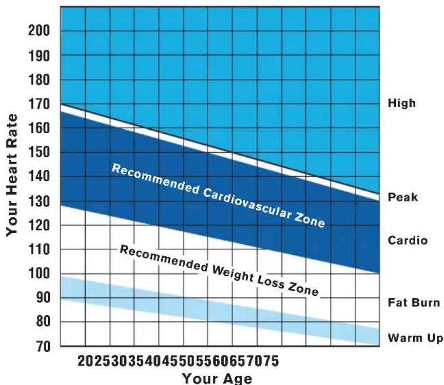
Figure 5: Heart rate target zones
CAUTION: Your heart rate should never exceed 85% of your maximum aerobic heart rate. You can calculate your maximum heart rate using the following formula:
Maximum heart rate = 207 - (your age × 0.67)
Using a Chest Strap Transmitter
WARNING
Signals used by the chest strap transmitter (or heart rate strap) may interfere with pacemakers or other implanted devices.
Consult your physician and the manufacturers of your chest strap transmitter and implanted device before using a chest strap transmitter.
Wearing a chest strap transmitter during your workout provides steady heart rate information. For the equipment to detect your heart rate, you must grip the touch heart rate sensors or wear a chest strap transmitter while exercising. In the presence of both touch and wireless data, the touch data takes precedence and will display.
Note: To receive an accurate reading, the strap needs to be in direct contact with the skin on the lower sternum (just below the bust line for women).
To use a chest strap transmitter:
- Carefully dampen the back of the strap with tap water.
Important: Do not use deionized water. It does not have the proper minerals and salts to conduct electrical impulses. - Adjust the strap and fasten it around your chest. The strap should feel snug, not restrictive.
- Make sure that the chest strap is right-side-up, lies horizontally across, and is centered in the middle of your chest.
- Test the chest strap placement by checking the heart rate function on the equipment. If a heart rate is registering, your chest strap placement is correct. If the equipment does not register a heart rate, readjust the strap and recheck the heart rate function.
Using the Treadmill Safety Clip
The treadmill is equipped with three different stop functions, which behave as follows:
If the user ... Then the
And the console ...
treadmill belt ...
Pulls on the lanyard attached to the safety clip and trips the restart switch
Slows to a stop
Shows the words PUSH THE RESET SWITCH. On some console models, an arrow points toward the Restart switch.

Presses down on the red STOP button
Slows to a stop
Shows that the exercise workout is paused.

Steps off of the running belt for a preset amount of time
Slows to a stop
Shows that the exercise workout is paused.
The restart switch and the red STOP button are located just below the console, as shown in the following figure. When the switch is tripped, the button pops up. The treadmill does not operate until the button is returned to its normal position.
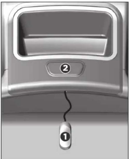
natural_image
Close-up of a car interior panel with a mouse and cable, no visible text or symbolsFigure 6: Restart switch
Instruct users on how important it is to use the safety clip while exercising on the treadmill, and demonstrate how they should attach it to their clothing near the waistline.
If the restart switch trips during exercise, perform the following steps:
- Reattach the safety clip if necessary.
- Press the restart switch down until it clicks, returning it to its normal position.
Note: If the restart switch trips, all information about the current workout is deleted. - Start the workout from the beginning, reducing the time as needed to account for the amount of exercise that has been completed.

natural_image
Line drawing of a hand holding a car seatbelt, showing the grip and seat area (no text or symbols)Figure 7: Attaching the safety clip
Tip: The small, flexible tab underneath the restart switch is designed for storage of the safety clip. When the treadmill is not in use, attach the safety clip to the tab as shown in the following figure.
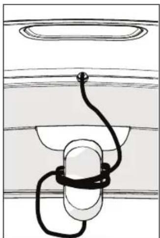
natural_image
Simple line drawing of a cable or rope attached to a spherical object, with no text or symbols present.Figure 8: Safety clip storage
Treadmill Auto Stop™ (Automatic Stop) Function
Important: The default setting for this feature is ON. An administrator can turn off this feature in the System Settings; however, Precor recommends it remain ON.
The Auto Stop ^™ (Automatic Stop) feature is designed to bring the treadmill to a gradual stop when it is not in use. This might occur if a user steps off the treadmill before the end of a workout and leaves the treadmill running.
60 seconds after a treadmill workout starts, or 30 seconds after it resumes, the equipment begins Auto Stop monitoring. If a user is detected, then no message appears, and the selected workout continues.
If no user is detected after an additional 30 seconds, the console displays the message NO USER DETECTED, STOPPING IN 10 SECONDS as notification of the pending stop. During the display of this message, a ten second countdown begins. If a user does not override the countdown, the belt comes to a gradual stop after the countdown is complete.
Note: Users weighing more than 50 pounds (22.7 kg) are detected within the speed and position limits of the feature. Users weighing less than 50 pounds (22.7 kg) may not be detected depending on their speed and location. Always be aware of the console's instructions and follow them for proper operation.
Starting a Workout
CAUTION: If you are using a treadmill, be sure to attach the security clip to your clothing before starting your workout.
The equipment is in the Welcome state when the words SELECT A WORKOUT OR PRESS QUICKSTART TO BEGIN scroll across the scrolling text display.
If the equipment is connected to CSAFE, the words SELECT A WORKOUT, PRESS QUICKSTART, OR ENTER TO BEGIN scroll across the text display.
If anything else appears on the screen, press Pause to display the Welcome banner.
From this screen, there are two ways to begin a workout:
- Press Quick Start™.
This action launches the Manual program. Calculations, such as calories used, are based on a 150-lb (68 kg), 35-year old person.
- Press one of the preset workout buttons.
When a user reaches the club time limit during a workout, the words number MINUTE CLUB TIME LIMIT REACHED, WORKOUT ENDING (where number is the number of minutes set as the club time limit) appear in the text display.
Starting a Preset Programmed Workout
Preset workouts are a great way to tailor your workouts to your fitness goals, stay challenged, and add variety to your sessions. These workouts are arranged in the following categories:
- Manual
- Heart Rate
- Interval
- Weight Loss
- Variety
- Performance
Pausing and Resuming an Exercise Session
When you interrupt a workout, the equipment responds in one of two ways, depending on how it is powered.
Paused (Externally Powered Equipment)
When the session is paused, the belt speed is slowly reduced to zero, or the resistance is slowly reduced to the minimum. The lift motor is turned off leaving the incline or crossramp at its current position. Data entry is canceled.
When you press Pause on all non-treadmill equipment, it displays the summary screen with your workout metrics. After displaying the summary, it returns to the Welcome screen.
Pending Shutdown (Self-Powered Equipment)
On self-powered machines, the paused state is equivalent to the pending shutdown state. When you stop working out, the equipment begins a 30 second countdown.
The accumulated metrics (e.g., time, strides, distance, calories) hold their current values and do not change. Data entry may not be started.
To restart the program, begin working out again. The resistance is reset to what it was when the program was paused.
If the equipment remains inactive for more than 30 seconds, the power is lost and the equipment bypasses the workout summary screen.
Ending a Session
Cooling down is an important aspect of your workout because it helps reduce muscle stiffness and soreness by transporting excess lactic acid out of the working muscles. In addition, a three to five minute cool down allows your heart rate to return to its normal, resting state.
At the end of your workout, a Summary screen displays your average heart rate during your workout and your accumulated workout metrics.
If you performed a fitness test exercise program, an initial message presents a fitness score.
The next two messages display the user's average and maximum heart rate during the session. These messages are only displayed if heart rate data was acquired during the session, i.e., a valid heart rate number was displayed at least once during the session.
The summary state times out in two minutes, causing a return to the Welcome banner. If the machine is in a CSAFE Finished state then the summary state must last for at least the CSAFE timeout value, typically 10 seconds or less. If it has not lasted that long, then before returning to the Welcome banner, the word RESETTING appears until the CSAFE finished state ends.
Three different types of metrics are captured during a workout.
Controlled Metrics can be set and changed. They include:
• Resistance Level (AMT, EFX, bike)
- Speed (treadmill)
- Incline (treadmill)
- Crossramp (EFX)
Current Performance Metrics describe the intensity of a workout in real time. They include:
- Pace (treadmill)
- Heart Rate
- Speed (bike)
• Revolutions/Minute (bike) - Strides/Minute (AMT, EFX)
- Watts (bike)
Accumulated Metrics describe the overall performance throughout the entire exercise session. They include:
- Time Elapsed
- Time Remaining
- Distance
- Calories
- Time (bike)
• Total Strides (EFX)
• Average Speed (treadmill)
Workouts
Your fitness equipment includes a wide selection of workouts that are carefully designed to make sure you get the best results out of every workout.
The human body is extremely efficient. If it makes the same motion regularly over many days or weeks, it learns to make that motion with less and less effort. This process, called muscle adaptation, has one drawback—the longer you stick to the same workout, the less good that workout does you.
To prevent muscle adaptation from setting in as you work out, try different kinds of workouts on different days. By keeping your muscles guessing, you'll keep your energy use up, promoting faster weight loss and better conditioning.
The workouts in the following table are available on units equipped with the P10 console.
Table 6. P10 Console Workouts
| Console Key | Workout AMT EFX Treadmill | Bike | ||
| Weight Loss | Weight Loss | ✓ | ✓ | ✓ |
| Heart Rate Basic Heart Rate Control (HRC) | ✓ ✓ | ✓ ✓ | ||
| Performance | Track | ✓ | ||
| Hill Climb ✓ | ✓ | |||
| Cross Training Workouts | ✓ | |||
| Fitness Test | ✓ | |||
| Variety | Random | ✓ | ✓ | |
| Gluteal Workouts | ✓ | |||
| Interval | 1-1 and 1-2 Interval | ✓ | ✓ | |
| Custom Interval | ✓ | |||
| Manual | Manual | ✓ | ✓ | ✓ |
The following listing describes these workouts.
Weight Loss Key
Pressing the Weight Loss key scrolls through the workouts that are designed to encourage weight loss and aerobic conditioning.
The American College of Sports Medicine ^® recommends that adults get at least 30-60 minutes of moderately intense exercise five days a week. The Weight Loss workout provides a structured and time-based aerobic challenge designed to help you reverse or prevent weight gain.
The total time for this workout is fixed at 28 minutes. It consists of alternating four-minute work and rest intervals. During the work intervals, you can change the resistance at any time.
Training tip: For best results, wear a heart rate monitor and maintain a target heart rate that is between 50% and 70% of your maximum heart rate.
Heart Rate Key
Pressing the Heart Rate key selects the Basic Heart Rate Controlled (HRC) workout, which monitors your heart rate to guide you through a moderate intensity program that is optimal for aerobic conditioning. To use this workout, you must either wear a chest strap sensor (recommended) or maintain continuous contact with the handheld sensor grips.
Note: You cannot switch to this workout during an exercise session.
During the workout, your target heart rate is based on the following calculation:
Target heart rate = 70% × (207 - (0.67 × your age))
The equipment adjusts intensity settings to maintain your target heart rate while you work out.
When a heart rate signal is not received, the metrics displays remain blank. If this happens, recheck your hand grip on the handheld sensors or the placement of your chest strap.
Training tip: This program offers a coaching benefit for new and returning users who are learning how to maintain a moderate, steady exertion level throughout their workouts.
Performance Key
Press the Performance key repeatedly to select a workout that conditions and tests the body's muscular and aerobic performance.
Note: On treadmills, a fitness test option is also available. A technician at the fitness facility must activate the fitness test before you can use it. After the test has been activated, you can scroll between the Track and Fitness Test workouts by pressing the Performance key repeatedly.
Track
This workout is largely identical to the Manual workout; there are no preset intensity levels, so you can adjust the levels as you work out. However, in place of the normal intensity graph, a diagram depicting an oval running track appears on the lower display. A blinking LED shows where you are in your current lap, and each lap is equal to 440 yards (400 meters).
Training tip: Challenge yourself by adjusting your training parameters regularly for the best results.
Hill Climb
This workout simulates a walk, run, or ride up a long grade and down a shorter one. It engages a wide range of muscle groups by adjusting the resistance, CrossRamp, or both to deliver a hill climbing experience. You can change these settings at any time, and your changes will affect the intensity of the rest of your workout.
Note: On the EFX, the console prompts you to pedal backward during part of the workout.
Training tip: Incorporating hill climb workouts into your regular cardio schedule will keep your workouts varied and help build lower body muscle strength.
Cross Training Workouts
This workout delivers true training variety and muscular engagement by adjusting the resistance and incline continuously to simulate the dynamic terrain of an outdoor run.
The CrossRamp setting is preprogrammed in each of these workouts, but you can change it or the resistance setting at any time. Your changes are applied to the levels for the remainder of your workout, and the columns in the workout profile show the changed CrossRamp levels.
Training tip: Advanced users can engage their core stabilizer muscles more thoroughly by taking their hands off the handlebars throughout the workout.
Fitness Test
Fitness tests evaluate your body's overall fitness in terms of its aerobic capacity. During the warmup stage of the test, you can adjust your starting resistance settings. After that, you complete a series of stages of increasing intensity. Based on your progress through these stages and the changes in your heart rate as you complete them, the equipment calculates your fitness score at the end of the test.
On treadmills, the Gerkin Fitness Test compares your fitness level with the official fitness standards of the International Association of Firefighters (IAFF). This test is written using the Gerkin Protocol, which is the basis for the official IAFF fitness test and part of their Wellness and Fitness Initiative.
The treadmill ends the test prematurely if any of the following things happen:
- The equipment cannot detect your heartbeat.
- Your heart rate exceeds 85% of your maximum safe rate for 15 seconds or more.
- Your heart rate changes too quickly.
- You press the STOP switch or pull on the safety clip lanyard.
Important: For best results, sit and rest for at least five minutes before you take the test.
Training tip: To see how your performance level increases with exercise over time, try taking the fitness test as soon as possible after you begin your exercise program. Then, as you keep working out, take the fitness test from time to time and watch your results improve.
The following tables show how to interpret your test score.
Table 7. Fitness score categories for women
| Age in Years | Low Fitness | Medium Fitness | High Fitness |
| 20-39 | 28 or below 28-34 | 34 or above | |
| 40-49 | 26 or below 26-32 | 32 or above | |
| 50-59 | 24 or below 24-29 | 29 or above | |
| 60 or over | 22 or below 22-27 | 27 or above |
Table 8. Fitness score categories for men
| Age in Years | Low Fitness | Medium Fitness | High Fitness |
| 20-39 | 35 or below 35-43 | 43 or above | |
| 40-49 | 32 or below 32-40 | 40 or above | |
| 50-59 | 29 or below 29-37 | 37 or above | |
| 60 or over | 24 or below 24-32 | 32 or above |
Variety Key
Pressing the Variety key selects a random or specialized workout designed for the fitness equipment you are using.
Random
Variety (for both the muscles and the mind) is the key to continued success for every exercise goal. The Random workout delivers a different training profile every time you select it. The one-minute segments that appear in the workout profile maintain a set incline that you can override.
Training tip: Your body will respond differently to each workout. The best way to evaluate and quantify the effectiveness of each exercise session is to wear a chest strap or use the touch-sensitive grips during your training sessions.
Gluteal Workouts
Strong glutes contribute to better posture, improved spine and hip stabilization, and reduction in lower body injuries at the hips, knees and ankles. These workouts target your thighs and glutes as they gradually increase in intensity, but you can modify the intensity levels at any time.
On EFX models, the workout prompts you to reverse direction after 25%, 50%, and 75% of the total time. At these points, you will see text messages on the console that remind you to change direction.
Training tip: To increase your core activation (the effort expended by your torso and gluteal muscles) during your workout, take your hands off the machine handles or handrails while maintaining an upright posture.
Interval Key
Interval workouts help exercisers improve strength, endurance, aerobic and anaerobic fitness. They alternate short bursts of high intensity activity with recovery periods. Pressing the Interval key selects the available interval workout.
Note: On the AMT, two different interval workouts are available. Press the Interval key repeatedly to scroll between the available workouts.
1-1 and 1-2 Interval
The 1-1 Interval workout is designed to raise and lower your heart rate in a repeating fashion for a user-defined period of time by alternating rest and work intervals of two minutes each. Likewise, the 1-2 Interval workout alternates two minutes of rest with four minutes of work.
Training tip: You can tailor your rest and work period intensity further by adjusting either of the intensity settings at any time. The equipment remembers these preferences for each upcoming interval.
Custom Interval
The Custom Interval workout is similar to the Interval workout. However, before you begin, you must specify the length of the rest and work intervals. Use either the arrow keys or the keypad to select a duration between 1 and 30 minutes, then press OK to enter your selection. After you have entered both durations, your workout begins.
Training tip: Depending on your fitness level and workout goals, you can set your recovery period as low as one minute between work intervals. For the work intervals themselves, you can set any duration between 1 and 30 minutes. Customizing the proportions of your work and rest intervals based on your unique training objectives will speed your progress toward your performance goals.
Manual Key
The workout available through the Manual key motivates you by allowing you to define and track your exertion levels throughout your exercise session.
Training tip: As you progress through your workout, each segment of the profile reflects the last change you made to the intensity settings. Challenge yourself by adjusting your training parameters regularly for the best results.
Maintenance
To keep the equipment functioning properly, perform the minor maintenance tasks in this section at the intervals suggested. Failure to maintain the equipment as described in this section could void the Precor Limited Warranty.
DANGER
To reduce the risk of electrical shock, always disconnect the equipment from its power source before cleaning it or performing any maintenance tasks. If the equipment uses an optional power adapter, disconnect the adapter.
Cleaning the Console and Display
The console requires little maintenance once installed. Precor recommends that you clean the console before and after each exercise session.
To remove dust and dirt from the console:
- Wipe all exposed surfaces with a soft cloth that you have moistened with a solution of 30 parts of water to 1 part of Simple Green® (for more information, visit
www.simplegreen.com).
Important: Do not use any acidic cleaners. Doing so will weaken the paint or powder coatings and void the Precor Limited Warranty. Never pour water or spray liquids directly on the console or console's screen.
- It is important to avoid using any corrosive chemicals on the console or screen.
- Always dampen the cloth and then clean the screen. Be sure to spray the cleaning liquid onto the cloth, not the console, so that drips do not seep into the console.
- Apply the cleaner with a soft, lint-free cloth. Avoid using gritty cloths.
Checking and Resetting the Active Status Light (Treadmill Only)
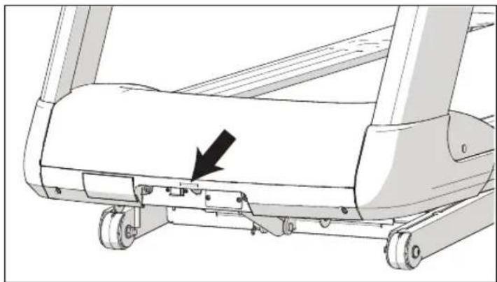
Experience Series treadmills manufactured after June 2014 include many improvements in design, function, and usability. One of those improvements is the status indicator light at the front of the treadmill hood, which gives a club owner or technician an easy way to check up on the condition of the treadmill.
natural_image
Technical line drawing of a treadmill with a black arrow pointing to the side panel (no text or symbols present)Figure 9: Status light location
Table 9. Active status light appearances and their meanings
| Status light appearance | Meaning | Action required |
| Steady (solid) blue | The treadmill is operating normally and does not currently need maintenance. | None. |
| Pulsing blue | The treadmill is due for scheduled maintenance (P80 console only), or the treadmill belt needs to be replaced (except for 230 V models). | Perform the needed maintenance, then reset the status light. |
| Steady (solid) yellow | The treadmill has detected and recovered from an error. It can still be used, but some functions may not be available. | Refer to the console's event log for more information. |
| Pulsing yellow | The treadmill has detected an error, has been unable to recover from the error, and has taken itself out of service. | Power-cycle the treadmill (switch it off, wait 30 seconds, then switch it on again). If the error occurs again, check the console's event log for more information, then contact Precor Customer Support. |
Important: Contact Precor Customer Support before running any of the diagnostic tests on the Hardware Validation menu.
To review and reset the status of the treadmill:
- At the Welcome banner, press the Pause key, then enter the following digits on the keypad:
51765761
- Use the up and down arrow keys to scroll through the menu names until HARDWARE VALIDATION appears.
- In the Hardware Validation menu, use the up and down arrow keys to scroll through the menu options until ACTIVE STATUS LIGHT appears, then press OK again.
- Press and hold the Quick Start key until the status light returns to a steady blue color.
- Press the Pause key to return to the Welcome banner.
Note: If the status light is steady yellow, you can also clear it by reviewing and clearing the entries in the event log (refer to Viewing the Informational Displays).
To adjust the brightness of the status light:
- At the Welcome banner, press the Pause key, then enter the following digits on the keypad:
51765761
- Use the up and down arrow keys to scroll through the menu names until HARDWARE VALIDATION appears.
- In the Hardware Validation menu, use the up and down arrow keys to scroll through the menu options until AS LIGHT BRIGHTNESS appears, then press OK again.
- Scroll through the available settings (LOW, MED, and HIGH) to select the brightness level you want, then press OK.
Changing the Belt (AMT Only)
The AMT uses belts to provide motion. These belts eventually wear and must be replaced.
When the belt stride count reaches 90 million, the message BELTS MUST BE CHANGED SOON scrolls on the Welcome screen. While this message appears, the AMT operates normally.
Important: If this message displays on your AMT, please contact Precor Customer Support for assistance.
When the belt stride count reaches 100 million (and the belt has not been changed), the message BELTS CHANGE
REQUIRED scrolls continuously on the Welcome screen. The input keys are not functional and the user cannot enter values or begin a workout until the belts are changed. Please contact Precor Customer Support to schedule a belt change.
Notes 55
Notes:
56 Operating and Maintaining the P10 Console
Notes:
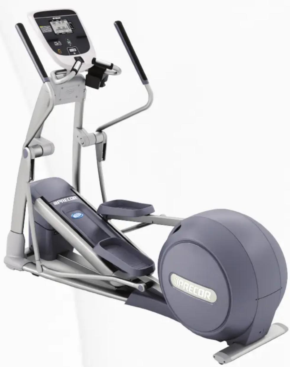
Assembling and Maintaining the EFX® 811 Elliptical Fitness Crosstrainer™
natural_image
Exterior view of a modern IIPRECOR stationary exercise machine (no signage or text visible on the device itself)Assembling and Maintaining the EFX® 811 Elliptical Fitness Crosstrainer™
Edition Information
ASSEMBLING AND MAINTAINING THE EFX 811 ELLIPTICAL FITNESS CROSSTRAINER
P/N 300763-201 rev E
Copyright © December 2014 Precor Incorporated. All rights reserved. Specifications subject to change without notice.
Trademark Note
Precor, AMT, EFX, and Preva are registered trademarks of Precor Incorporated. Other names in this document may be the trademarks or registered trademarks of their respective owners.
Intellectual Property Notice
All rights, title, and interests in and to the software of the Preva Business Suite, the accompanying printed materials, any copies of such software, and all data collected via the Preva Business Suite, are exclusively owned by Precor or its suppliers, as the case may be.
Precor is widely recognized for its innovative, award-winning designs of exercise equipment. Precor aggressively seeks U.S. and foreign patents for both the mechanical construction and the visual aspects of its product design. Any party contemplating the use of Precor product designs is hereby forewarned that Precor considers the unauthorized appropriation of its proprietary rights to be a very serious matter. Precor will vigorously pursue all unauthorized appropriation of its proprietary rights.
Precor Incorporated 20031 142nd Ave NE, P.O. Box 7202 Woodinville, WA 98072-4002 1-800-347-4404
http://www.precor.com
Important Safety Instructions
Important: Save these instructions for future reference.
Read all instructions in the documentation provided with your exercise equipment, including all assembly guides, user guides, and owner's manuals, before installation of this device.
Note: This product is intended for commercial use.
The display apparatus (hereinafter referred to as the console) is intended to be shipped with new Precor exercise equipment (hereinafter referred to as the base unit). It is not packaged for individual sale.
WARNING
To prevent injury, the console must be attached securely to the base unit following all assembly and installation instructions shipped with the base unit. The console is intended to be connected to AC mains power through the furnished power supply ONLY. It should be powered on only when installed as described in the assembly and installation instructions shipped with the base unit. The console is intended for use only with Precor fitness equipment, not as a standalone device.
Safety Precautions
Always follow basic safety precautions when using this equipment to reduce the chance of injury, fire, or damage. Other sections in this manual provide more details of safety features. Be sure to read these sections and observe all safety notices. These precautions include the following:
- Read all instructions in this guide before installing and using the equipment and follow any labels on the equipment.
- Make sure all users see a physician for a complete physical examination before they begin any fitness program, particularly if they have high blood pressure, high cholesterol or heart disease; have a family history of any of the preceding conditions; are over the age of 45; smoke; are obese; have not exercised regularly in the past year; or are taking any medication.
- Do not allow children, or people unfamiliar with the operation of this equipment, on or near it. Do not leave children unsupervised around the equipment.
- Make sure all users wear proper exercise clothing and shoes for their workouts and avoid loose or dangling clothing. Users should not wear shoes with heels or leather soles, and they should check the soles of their shoes to remove any dirt and embedded stones. They should also tie long hair back.
- Never leave the equipment unattended when it is plugged in. Unplug the equipment from its power source when it is not in use, before cleaning it, and before providing authorized service.
Note: The optional power adapter is considered a power source for self-powered equipment.
- Use the power adapter provided with the equipment. Plug the power adapter into an appropriate, grounded power outlet as marked on the equipment.
- Care should be taken when mounting or dismounting the equipment.
- For Treadmills: Do not use typing or web surfing features while walking at speeds that exceed a slow and relaxed leisurely pace. Always stabilize yourself by holding a stationary handle bar while using typing or web surfing features.
- For AMT and EFX: Always stabilize yourself by holding a stationary handle bar while using typing or web surfing features.
- Read, understand, and test the emergency stop procedures before use.
- Keep the power cord or optional power adapter and plug away from heated surfaces.
- Route power cables so that they are not walked on, pinched, or damaged by items placed upon or against them, including the equipment itself.
- Ensure the equipment has adequate ventilation. Do not place anything on top of or over the equipment. Do not use on a cushioned surface that could block the ventilation opening.
- Assemble and operate the equipment on a solid, level surface.
- SPACING—The below minimum spacing recommendations are based on a combination of the ASTM (U.S.) voluntary standards and EN (European) regulations as of October 1, 2012, for access, passage around, and emergency dismount:
- Treadmills—a minimum of 0.5 m (19.7 in.) on each side of the treadmill and 2 m (78 in.) behind the machine.
- Cardio equipment other than treadmills—a minimum of 0.5 m (19.7 in.) on at least one side, and 0.5 m (19.7 in.) behind or in front the machine.
Careful consideration should be given to the requirements of the Americans with Disabilities Act (ADA), US Code 28 CFR (see Section 305). ASTM
standards are voluntary and may not reflect current industry standards. The actual area for access, passage around, and emergency dismount is the responsibility of the facility. The facility should consider the total space requirements for training on each unit, voluntary and industry standards, and any local, state, and federal regulations. Standards and regulations are subject to change at any time.
Important: These spacing recommendations should be used when positioning equipment away from sources of heat, such as radiators, heat registers, and stoves. Avoid temperature extremes.
- Keep equipment away from water and moisture. Avoid dropping anything on or spilling anything inside the equipment to prevent electric shock or damage to the electronics.
- When using the treadmill, always attach the safety clip to your clothing before beginning your workout. Failure to use the safety clip may pose a greater risk of injury in the event of a fall.
- Keep in mind that heart rate monitors are not medical devices. Various factors, including the user's movement, may affect the accuracy of the heart rate readings. The heart rate monitors are intended only as exercise aids in determining heart rate trends in general.
-
Do not operate electrically powered equipment in damp or wet locations.
-
Never operate this equipment if it has a damaged cord or plug, if it is not working properly, or if it has been dropped, damaged, or exposed to water. Call for service immediately if any of these conditions exist.
- Maintain the equipment to keep it in good working condition, as described in the Maintenance section of the owner's manual. Inspect the equipment for incorrect, worn, or loose components, and then correct, replace or tighten prior to use.
- If you plan to move the equipment, obtain help and use proper lifting techniques.
- Equipment Weight Restrictions: Do not use the treadmill if you weigh more than 400 pounds (180 kg). If you weigh more than 350 pounds (160 kg), do not run on the treadmill. For all other fitness equipment, the weight limit is 350 pounds (160 kg).
- Use the equipment only for its intended purpose as described in this manual. Do not use accessory attachments that are not recommended by Precor. Such attachments may cause injuries.
- Do not operate the equipment where aerosol (spray) products are being used or where oxygen is being administered.
- Do not use outdoors.
- Do not attempt to service the equipment yourself, except to follow the maintenance instructions in the owner's manual.
- Never drop or insert objects into any opening. Keep hands away from moving parts.
- Do not set anything on the stationary handrails, handlebars, control console, or covers. Place liquids, magazines, and books in the appropriate receptacles.
- Do not lean on or pull on the console at any time.
CAUTION: DO NOT remove the cover, or you may risk injury due to electric shock. Read the assembly and maintenance guide before operating. There are no user-serviceable parts inside.
Contact Customer Support if the equipment needs servicing. For use with single phase AC power only.
Educating Users
Take time to educate users about the Important Safety Instructions found in both the User Reference Manual and Product Owner's Manual. Explain to your club or facility patrons that they should observe the following precautions:
- Hold onto a stationary handrail or handlebar while assuming the starting position on the equipment.
• Face the console at all times. - Hold on to a stationary handrail or handlebar with one hand whenever you operate the console keys with the other hand.
Hazardous Materials and Proper Disposal
The batteries within self-powered equipment contain materials that are considered hazardous to the environment. Federal law requires proper disposal of these batteries.
If you plan to dispose of your equipment, contact Precor Commercial Products Customer Support for information regarding battery removal. Refer to Obtaining Service.
Product Recycling and Disposal
This equipment must be recycled or discarded according to applicable local and national regulations.
Product labels, in accordance with European Directive 2002/96/EC concerning waste electrical and electronic equipment (WEEE), determine the framework for the return and recycling of used equipment as applicable throughout the European Union. The WEEE label indicates that the product is not to be thrown away, but rather reclaimed upon end of life per this Directive.
In accordance with the European WEEE Directive, electrical and electronic equipment (EEE) is to be collected separately and to be reused, recycled, or recovered at end of life. Users of EEE with the WEEE label per Annex IV of the WEEE Directive must not dispose of end of life EEE as unsorted municipal waste, but use the collection framework available to customers for the return, recycling, and recovery of WEEE. Customer participation is important to minimize any potential effects of EEE on the environment and human health due to the potential presence of hazardous substances in EEE. For proper collection and treatment, refer to Obtaining Service.
Regulatory Notices for the RFID Module
When equipped with a control console as described in this document, this equipment may include a radio-frequency identification (RFID) module. The RFID module has been certified to operate at temperatures between -20^ and 85^ ( -4^ and 185^ ).
Radio Frequency Interference (RFI)
The RFID module conforms to the following national standards defining acceptable limits for radio frequency interference (RFI).
Federal Communications Commission, Part 15
This equipment has been tested and found to comply with the limits for a Class A digital device, pursuant to Part 15 of the FCC Rules. These limits are designed to provide reasonable protection against harmful interference in a commercial installation. The equipment generates, uses, and can radiate radio frequency energy and, if not installed and used in accordance with the owner's manual instructions, can cause harmful interference to radio communications.
Operation is subject to the following two conditions: (1) this device may not cause harmful interference, and (2) this device must accept any interference received, including interference that may cause undesired operation.
WARNING
Per FCC rules, changes or modifications not expressly approved by the manufacturer could void the user's authority to operate the equipment.
Industry Canada
This device complies with RSS-210:2007 of the Spectrum Management & Telecommunications Radio Standards Specification. Operation is subject to the following two conditions: (1) this device may not cause harmful interference, and (2) this device must accept any interference received, including interference that may cause undesired operation.
This Class A digital apparatus complies with Canadian ICES-003.
European Applications
CE compliance is claimed to the following directives:
• 1999/5/EC R&TTE Directive
• 2006/95/EC LVD Directive
• 2002/95/EC RoHS Directive
Directive compliance has been verified to the following standards:
• EN 55022
• EN 300 330-1 V1.5.1
• EN 300 330-2 V1.3.1
• EN 301 489-3 V1.4.1
• EN 301 489-1 V1.8.1
- EN 60950-1
Regulatory Notices for Cardiovascular Exercise Equipment
The regulatory information in this section applies to the exercise equipment and its control console.
Safety Approvals for Cardiovascular Equipment
Precor equipment has been tested and found to comply with the following applicable safety standards.
Cardiovascular Type Equipment:
• CAN/CSA, IEC, EN 60335-1 (Household and similar electrical appliances - Safety)
• EN 957 (Stationary training equipment, class S/B compliant equipment)
PVS and P80 Regulatory Notice
This Precor equipment has been tested and found to comply with the following applicable safety standards.
• CAN/CSA, UL, IEC, EN 60065 (Audio, video and similar electronic apparatus - Safety)
Radio Frequency Interference (RFI)
This Precor exercise equipment conforms to the following national standards defining acceptable limits for radio frequency interference (RFI).
Federal Communications Commission, Part 15
This equipment has been tested and found to comply with the limits for a Class A digital device, pursuant to Part 15 of the FCC Rules. These limits are designed to provide reasonable protection against harmful interference in a commercial installation. The equipment generates, uses, and can radiate radio frequency energy and, if not installed and used in accordance with the owner's manual instructions, may cause harmful interference to radio communications.
WARNING
Per FCC rules, changes or modifications not expressly approved by Precor could void the user's authority to operate the equipment.
Industry Canada
This Class A digital apparatus complies with Canadian ICES-003.
European Applications
CE compliance is claimed to the following directives:
• 2004/108/EC EMC Directive
• 2006/95/EC LVD Directive
• 2002/95/EC RoHS Directive
Directive compliance has been verified to the following standards:
• EN 55022
• EN 55024
• EN 60335-1
• EN 60065 (P80 and PVS)
Electrical Recommendations: All Equipment Excluding Treadmills
Note: This is a recommendation only. NEC (National Electric Code) guidelines or local region electric codes must be followed.
For equipment fitted with a P80 console or Personal Viewing System (PVS) screen a separate power connection is required. For a 20 amp branch circuit up to 10 screens can be connected. If the branch circuit has any other devices plugged into the circuit, then the number of screens must be reduced by the wattage of the other devices.
Note: The typical splitter power cords that have IEC-320 C13 and C14 plugs have a recommended maximum capacity of five screens.
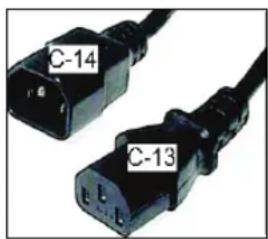
text_image
C-14 C-13Figure 1: IEC-320 C13 and C14 plugs
Obtaining Service
Do not attempt to service the equipment except for maintenance tasks. If any items are missing, contact your dealer. For more information regarding customer support numbers or a list of Precor authorized service centers, visit the Precor web site at http://www.precor.com.
Obtaining Updated Documentation
Current Precor product documentation is available at http://www.precor.com/productmanuals. You may want to check in for updated information from time to time.
Table of Contents
Important Safety Instructions .... 3
Safety Precautions....4
Educating Users 8
Hazardous Materials and Proper Disposal 8
Product Recycling and Disposal 8
Regulatory Notices for the RFID Module 9
Radio Frequency Interference (RFI)....9
Regulatory Notices for Cardiovascular Exercise Equipment ....11
Safety Approvals for Cardiovascular Equipment 11
Radio Frequency Interference (RFI)....12
Electrical Recommendations: All Equipment Excluding Treadmills....13
Obtaining Service....14
Obtaining Updated Documentation....14
Assembling the EFX....17
Installation Requirements....19
Required Tools....20
Hardware Kit (not to scale)....21
Assembling the EFX 23
Installing the Display Console Mount 25
Installing the Bottle Holder....27
Installing the Handlebars 28
Attaching the Caps and Upright Support Cover....31
Making Sure the Unit is Stable 33
Verifying that the Heart Rate Display is Operational....34
Breaking In the Equipment 34
Installing the Console 35
Threading the Console Cable Assembly 36
Connecting Cables 37
Completing the Console Installation....39
Self-Powered Features.... 41
Informational Displays Prior to Shutdown 43
Symptoms of a Low Battery 44
Using the Optional Power Adapter 44
The Optional Power Adapter Kit....45
Replacing the Battery 46
Maintenance....47
Daily Cleaning 48
Daily Inspection 49
Weekly Maintenance....50
Monthly Maintenance 51
Storing the Chest Strap....52
Moving the Equipment 52
Long-Term Storage....52
Assembling the EFX
WARNING
You will need the assistance of two other people to assemble this unit. DO NOT attempt assembly by yourself.
Important: The instructions in the following procedures are described from the perspective of a person standing directly in front of the equipment (that is, on the opposite side of the control console from a person using the equipment). These descriptions may not match the names of certain parts in the parts list, because such parts are named relative to the back of the equipment.
To prepare the EFX for assembly:
- Open the box and assemble the components in the sequence presented in this guide.
- Assemble and operate your equipment on a hard, level surface in the area intended for use.
• Use a hand truck or furniture dolly to move the EFX unit.
Important: Do not grasp the unit by any of its plastic parts to move it. The plastic parts are non-structural covers and are not capable of supporting the weight of the unit.
- Provide ample space around the unit.
- Assemble the equipment according to the guidelines in this manual to ensure that you do not void the Precor Limited Warranty.
Important: Any damage caused during installation is not covered by the Precor Limited Warranty.
- Begin installation of all fasteners by hand, then partially tighten them. Do not fully tighten fasteners until instructed to do so.
Important: When wrench-tightening the screws, make sure the head of the fastener is parallel to the product surface. If it is not, stop tightening to avoid cross-threading. To avoid further damage, stop assembly work and contact Customer Support.
Installation Requirements
Follow these installation requirements when assembling the unit:
- Assemble the unit near the location where you plan to use it.
- Provide ample space around the unit.
- Open space around the unit allows for easier access.
- Set up the unit on a solid, flat surface.
- A smooth, flat surface under the unit helps keep it level. A level unit has fewer malfunctions.
- Open the box and assemble the components in the sequence presented in this guide.
- The unit is shipped in one box. Ask for help from two or more people to unpack and assemble the Climber.
- Insert all fasteners with your fingers.
- Use your fingers to properly align and thread the fasteners. This helps alleviate cross-threading. Do not fully wrench tighten fasteners until instructed to do so.
Important: When wrench tightening, the head of the fastener should be flush with the product. If it is not, cross-threading may have occurred. Do not attempt to rework the assembly as more damage to the equipment will occur. Contact Customer Support. Refer to Obtaining Service.
- If you plan to move the unit, obtain help and use a hand truck.
- Do not grasp any plastic parts while lifting or moving the unit. The plastic parts are not capable of supporting the weight of the unit and they may break.
Required Tools
- Wire tie cutter
• Phillips-head screwdriver - Two 9 / 16 -inch combination wrenches (open-end and box)
• SAE Standard socket set
Hardware Kit (not to scale)
Table 1. Hardware Kit
| Fasteners | Quantity | ||
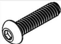 | Buttonhead screw (1-inch) | 14 | |
 | Washer ( 5116 -inch) | 20 | |
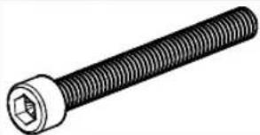 | Socket head cap screw ( 114 -inch) | 6 | |
 | Split washer ( 5116 -inch) | 20 | |
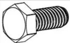 | Hex head screw ( 114 -inch) | 2 | |
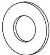 | Washer ( 318 -inch) | 4 | |
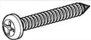 | Self-tapping screw ( 112 -inch) | 4 | |
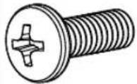 | Phillips-head screw ( 314 -inch) | 3 | |
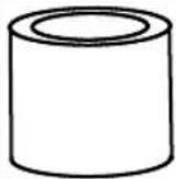 | Bushings 2 | ||
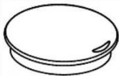 | Link arm caps | 2 | |
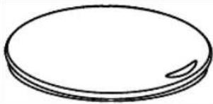 | Pivot arm caps | 2 | |
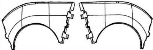 | Pivot axle covers | 2 | |
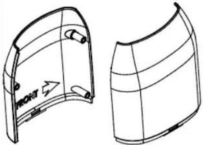 | Upright support covers (packaged separately) | 4 | |
Assembling the EFX
DANGER Do not attempt to connect electrical power until all assembly procedures are complete and the console is properly installed.
Assemble the EFX in the order presented. Once you have assembled it, clean the ramp with a soft cloth dampened in a diluted solution of mild soap and water.
To begin assembly:
- Feed the cable through the right upright support. Tape the cable to the top of the upright support to secure it temporarily.
Important: Do not stretch, crimp, or damage the cable. Cables damaged by improper installation will not be covered by the Precor Limited Warranty.
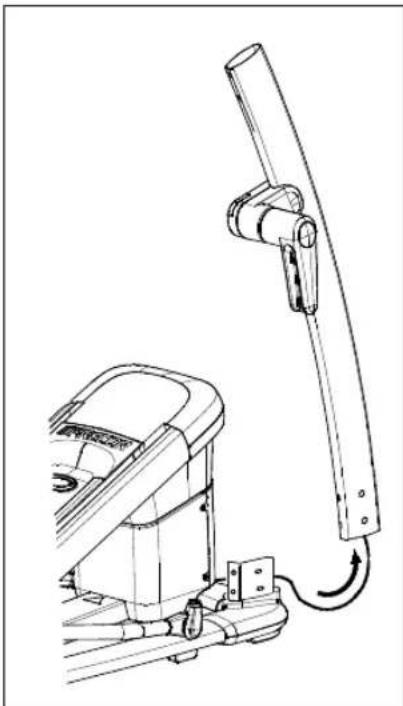
natural_image
Technical line drawing of a mechanical device with a curved bracket and attached lever (no text or symbols)Figure 2: Feed cable through right upright support
- Attach both upright supports to the base frame using eight buttonhead screws, eight split washers, and eight washers. Finger tighten.
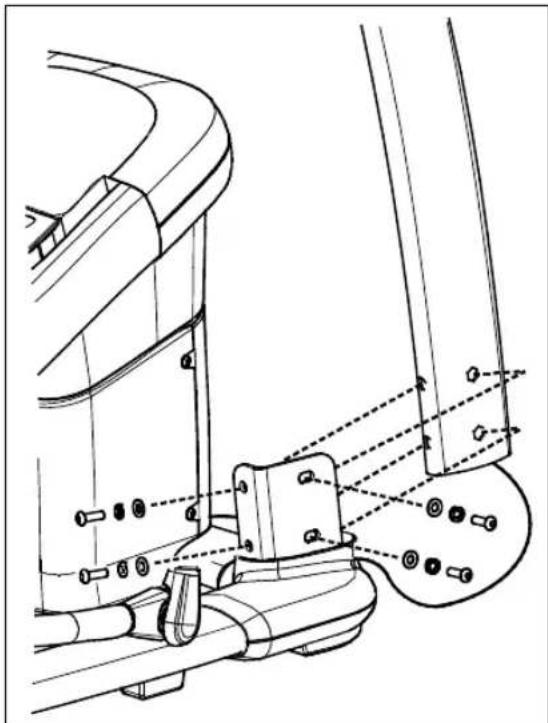
natural_image
Technical line drawing of a mechanical assembly with no visible text or symbolsFigure 3: Attaching the upright supports
Installing the Display Console Mount
- Ask your assistant to hold the display console mount above the upright supports while you connect the cable. Remove and discard the tape after you connect the cable.
Important: Place excess cable inside the upright support.
- Have your assistant lower the display console mount while you align the mounting brackets on the inside of the upright supports.
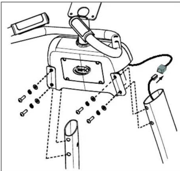
natural_image
Technical line drawing of a mechanical assembly with no visible text or symbolsFigure 4: Attaching the console mount to the upright supports
- Fasten the display console mount to each upright support by threading a buttonhead screw, washer, and split washer through opposite mounting holes. Check that the base fasteners are loose before installing the display console fasteners.
CAUTION: Make sure the display console mount screws are properly threaded into the inserts. Do not cross thread. The Precor Limited Warranty does not cover damage that occurs during installation.
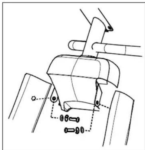
natural_image
Technical line drawing of a mechanical assembly with no visible text or symbolsFigure 5: Attaching the side bolts
-
Check alignments and thread the remaining four display console mount screws, four washers, and four split washers. Wrench tighten with a 316 -inch hex key so the assemblies come together, but leave room for adjustments.
-
When all fasteners are snug against the unit, begin at the base and alternately wrench tighten all fasteners. Follow the sequence from step 2 through step 5.
Installing the Bottle Holder
The bottle holder attaches to the right stationary arm handrail.
To install the bottle holder:
- Position the water bottle holder as shown and attach it to the right stationary handrail.
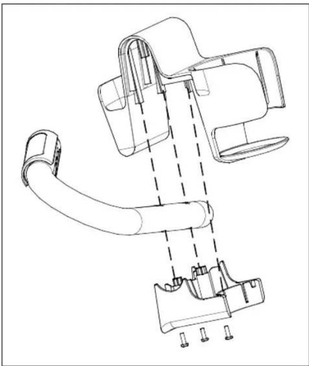
natural_image
Technical line drawing of a mechanical device with no visible text or symbolsFigure 6: Attaching the water bottle
- Secure the holder using three Phillips-head screws and a Phillips-head screwdriver.
Installing the Handlebars
CAUTION: Handlebars can swing and cause injury. Have your assistant hold the handlebar and gently lower it into a vertical position when the handlebar assembly is complete.
To install the moving handlebars:
- For proper alignment, rotate the pivot arm to a horizontal position. Apply pressure to fit the protrusion on the handlebar into the handlebar bracket.
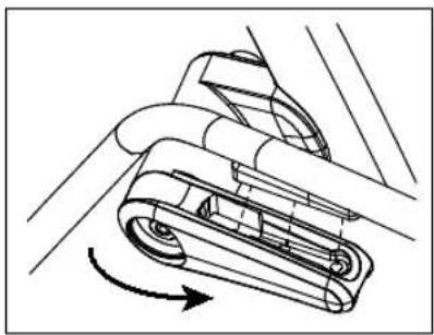
natural_image
Mechanical component diagram showing a lever mechanism with rotational motion indicated by an arrow (no text or symbols present)Figure 7: Handlebar and bracket attachment
- Insert three socket head cap screws, three split washers, and three washers through each handlebar bracket. To secure the handlebars, wrench tighten the fasteners using a 14 -inch hex key.
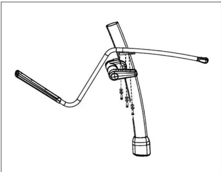
natural_image
Technical line drawing of a mechanical lever assembly (no text or symbols)Figure 8: Upper body handlebar attachment detail
- Attach the handlebars to the link arms using two hex head screws, two bushings, and four washers. For ease of installation, slide the corresponding foot pedal to the top of the ramp before attaching each handlebar.
Important: Install the fasteners in the order shown. The bushing slides inside the link arm. The heads of the screws remain on the ramp side of the link arm.
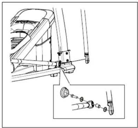
natural_image
Technical line drawing of a mechanical assembly with an inset showing a close-up of a component (no text or symbols present)Figure 9: Attaching the movable arms
- Wrench tighten the fasteners using a 916 -inch box-end or socket wrench.
Attaching the Caps and Upright Support Cover
You will need the arm caps and foot covers to complete the following tasks.
To attach the caps and upright support covers:
- Align the cut-out inside the link arm cap with the link arm mounting hole. Apply pressure to the cap until it snaps into place.

natural_image
Mechanical linkage diagram showing a lever system with pivot point and joint components (no text or labels)Figure 10: Attaching the link and pivot arm caps
- Attach the pivot arm caps.
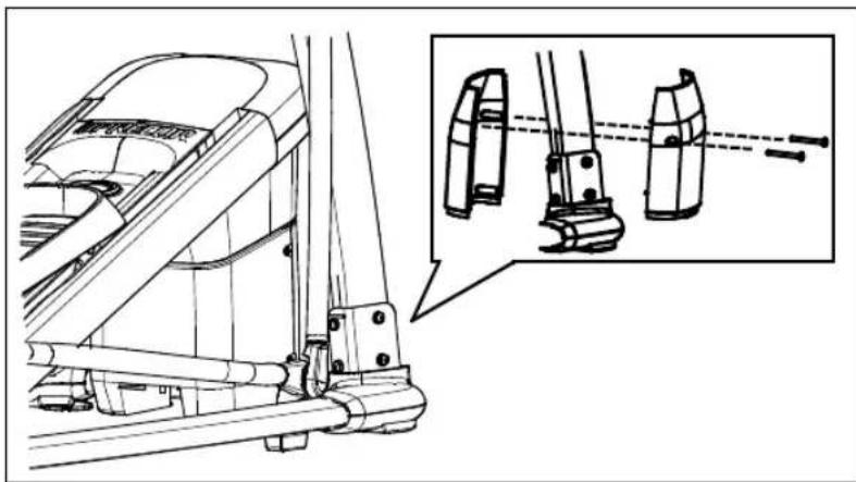
natural_image
Technical line drawing of a mechanical assembly with an inset showing a close-up of a component detail (no text or symbols present)Figure 11: Attaching the upright support covers
-
Place one inner and one outer upright support cover around an upright support. Align each pair so the arrows on the covers point toward the front of the unit. Apply pressure to engage the inner cover protrusions with the outer cover screw holes.
-
Slide the covers down into the base mount. Secure each pair of covers using two self-tapping screws and a Phillips-head screwdriver.
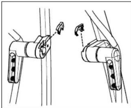
natural_image
Technical line drawing of two mechanical components with adjustment arrows (no text or symbols)Figure 12: Attaching the pivot axle covers
- Insert the two pivot axle covers and press firmly into place.
Making Sure the Unit is Stable
Make sure the unit is level before allowing anyone to use it.
CAUTION: To eliminate movement, make sure the adjustable feet are in contact with the floor.
To level the unit:
- Gently rock the unit. If there is any movement, ask your assistant to tip the unit to one side while you locate the adjustable feet.
- Correct the height of each adjustable foot as follows.
If you want to ... Then turn the adjustable feet ...
Raise the unit Counterclockwise
Lower the unit Clockwise
Important: Place the unit on a flat surface. Rotating the adjustable feet cannot compensate for extremely uneven surfaces.
When you are finished adjusting the unit, place the unit on the floor and recheck that it is level.
Verifying that the Heart Rate Display is Operational
To verify that the heart rate display is operational:
- Hold on to a stationary handrail and step on the foot pedals.
- When you are comfortably situated, begin pedaling. A pedaling speed above 40 strides per minute must be maintained for several seconds.
- Grasp both touch-sensitive handrail grips on the stationary handrails.
- Look at the HEART RATE display. After a few seconds, a number appears indicating your heart rate.
Note: If a number does not appear in the HEART RATE display, you may need to disassemble the unit and check the cable connection.
Breaking In the Equipment
Precor equipment does not require an actual break-in period. However, moving components such as belts, gears, and bearings can settle while the equipment is being stored or shipped. This can cause the equipment to operate with a small amount of roughness or noise when it starts up for the first time.
The equipment usually returns to smooth operation after a day or two of normal use. If it does not, contact your dealer for assistance. For more information, refer to Obtaining Service.
Installing the Console
To make installation easier, all Precor Experience Series consoles use the same mounting hardware and connector locations whenever possible. The installation sequence for any of them is as follows:
• Threading the console cable assembly
- Connecting cables
- Completing the installation (tightening the mounting screws and attaching the back cover)
The following sections describe how to perform these tasks.
Threading the Console Cable Assembly
Earlier in the installation, you threaded the necessary cables through the frame of the base unit and out the passthrough opening in the console mount. As you line up the back plate on the console with the console mount, you must make sure that the console cable assembly passes correctly through the openings in both components.
Important: Before you begin the following procedure, remove the rear cover from the control console. Set the cover and its mounting hardware aside for later use.
To thread the console cable assembly:
- Make sure that as much of each cable as possible passes through the opening in the middle of the console mount on the base unit.
- Position the console over the console mount.
- Rest the console on the console mount so that the notch on the bottom of the console's back plate rests on the rectangular hook at the bottom of the console mount, as shown in the following figure.
- Tilt the console forward until it stops. Use one hand to steady the console in this position, or ask your assistant to do so.
Connecting Cables
Important: Pass all cables through the semicircular opening just above the console mount, as shown in the following figure. Do not attempt to route any cables through other openings or through the steel channel above the mount.
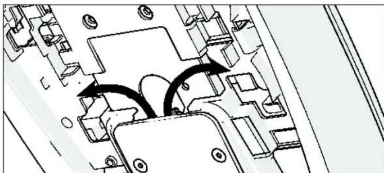
natural_image
Technical diagram of a mechanical assembly with no visible text or symbolsFigure 13: Cable routing from the mount into the console
After the console has been seated, separate the individual cables out of the end of the console cable assembly and attach them to the appropriate circuit connectors inside the console. Refer to the following diagram and table to identify the cables and connectors.
Important: All cables must pass through the opening in the center of the console mount.
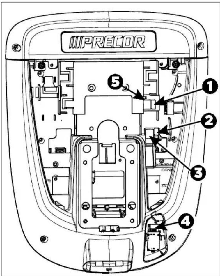
text_image
IIPRECOR ① ② ③ STC ④ ⑤Figure 14: Cable connections, P30 and P10 consoles
Table 2. P30 and P10 internal cable connections
| Cable Connector Type | Circuit |  |
| Safety key (treadmills only) | Six-contact strip, keyed | [5WGx] |
| Automatic stop sensor (treadmills only) | Four-contact strip, keyed |  |
| Data from base unit | Eight-contact modular, on flat gray cable |  |
| Heart rate sensors | Four-contact strip, keyed |  |
| CSAFE Eight-contact modular, on flat gray cable |  | |
Completing the Console Installation
Before you complete the final installation steps, double-check the connections you have made. Make sure that all cables are fully and securely connected, and that any unneeded cables are tied back properly.
To complete the installation:
- Feed extra cable back into the neck tube.
- Tilt the control console backward (toward yourself) until the tab on the top edge of its back plate slides along the top edge of the console mount and the screw holes align properly.
-
Insert the four 58 -inch flat head screws through the holes in the console mount and thread them into the holes in the back plate on the console. Partially tighten the screws using a 532 -inch hex wrench.
-
Line up the two small tabs at the bottom of the console's back cover with the slots at the bottom of the console case. Insert the tabs into the slots.
- Insert the two #8-32 x 1/2-inch Phillips-head screws that you removed earlier into the holes at the top edge of the console's back cover. Tighten the screws fully.
Important: Use caution not to pinch the cables between the back cover and PVS mounting screw heads. - Fully tighten the four mounting screws (partially tightened in step 3) using a 5/32 -inch hex wrench.
Self-Powered Features
Important: This chapter of the manual describes Precor fitness equipment that can operate without being connected to AC power. This includes units equipped with P30 or P10 consoles. However, P80 consoles must be connected to AC power through their power supplies to operate. For this reason, this chapter does not apply to units equipped with P80 consoles.
On self-powered equipment, the system initializes and displays the Welcome screen when a user starts exercising. A minimum rate of motion must be maintained for the banner to appear, as shown in the following table. When a person meets the requirements, the power that is generated allows the equipment to function properly.
Table 3. Minimum requirements for operation
| Equipment | Rate of Motion |
| AMT 40 strides per minute (SPM) | |
| EFX 40 strides per minute (SPM) | |
| Climber 30 steps per minute | |
| Bike 20 revolutions per minute (RPM) | |
Informational displays appear when the battery is low or when the rate of motion drops below the minimum requirements. The display explains what to do to retain power. If the messages are ignored, the equipment begins shutdown procedures to maintain the charge of the battery. Refer to Informational Displays Prior to Shutdown.
An optional power adapter can be purchased and provides sustained power to the equipment. If you plan to change the club settings on a unit equipped with a P30 or P10 console, the power adapter is highly recommended. To purchase the optional power adapter, check with your dealer. Refer to Obtaining Service.
Informational Displays Prior to Shutdown
The equipment saves its battery charge by moving into a shutdown mode. If the user does not maintain the minimum rate of motion, a 30-second shutdown process begins.
In this mode, the console displays a countdown indicator and ignores all key presses. If no movement is detected or the rate of motion remains below the minimum, the indicator changes as the countdown continues.
Note: The user can resume exercising before the countdown period elapses and the workout will continue from the point at which it was paused.
Important: If the equipment is connected to a CSAFE master device, it follows a slightly different shutdown process. Ten seconds before the equipment shuts down, it ends the exercise session and displays a reset message while it disconnects from the CSAFE master device. It ignores all key presses during these last ten seconds.
Symptoms of a Low Battery
If no one has used the equipment for an extended period of time, the battery may need recharging.
Symptoms of a low battery include the following:
• A flickering or erratic display
- Loss of user and program information after the user stops exercising, without any display of a workout summary or a notification of pending shutdown
- Inability to decrease the incline setting (if any)
Important: To maintain a constant power source, use the optional power adapter.
Using the Optional Power Adapter
After connecting the power adapter to the equipment, plug the opposite end into the appropriate power source (120 V or 240 V).
CAUTION: When the optional power adapter is in use, make sure that the power supply cord does not create a safety hazard. Keep it out of the way of traffic and moving parts. If the power supply cord or power conversion module is damaged, it must be replaced.
The control console functions differently when the power adapter is connected. Because the power adapter provides a constant source of power, a user can pause for brief periods without initiating shutdown procedures. When the pause time limit expires and the user has not resumed exercising, the console returns to the Welcome screen. The default pause time is 30 seconds for all fitness equipment. Refer to the manual for your control console for instructions on setting or changing the pause time limit. To learn how to install the power adapter, refer to The Optional Power Adapter Kit.
The Optional Power Adapter Kit
If you purchase the optional power adapter, you must also purchase the internal cable kit. The kit supplies the cable, bracket, and fasteners that connect the power adapter to the lower electronics board.
CAUTION: The internal cable kit must be installed by authorized service personnel. Do not attempt installation on your own as you could void the Precor Limited Warranty. For more information, refer to Obtaining Service.
Important: If this equipment includes a P80 console, the optional power adapter and the internal cable kit must still be installed to provide continuous power to the base unit and support its internal battery.
Once the internal cable kit is installed, you can plug the optional power adapter into the equipment. Plug the opposite end into the appropriate power source for your equipment (120 V or 240 V). Review the safety instructions found at the beginning of this manual before using the power adapter.
Replacing the Battery
The equipment's battery is built to last for a long time. However, if you feel that the battery may need replacing, check with an authorized service technician. Refer to Obtaining Service.
CAUTION: The battery stored inside the equipment contains hazardous materials and must be disposed of according to Hazardous Waste Regulations. Refer to Hazardous Materials and Proper Disposal.
Maintenance
To keep the equipment functioning properly, perform the minor maintenance tasks at the intervals shown in this section. Failure to maintain the equipment as described in this section could void the Precor Limited Warranty.
DANGER
To reduce the risk of electrical shock, always disconnect the equipment from its power source before cleaning it or performing any maintenance tasks. If the equipment is self-powered but also uses the optional power adapter, disconnect the adapter.
Daily Cleaning
Precor recommends that you clean the equipment before and after each exercise session. To remove dust and dirt from the equipment, wipe all exposed surfaces with a soft cloth that you have moistened with one of the following cleaners:
- A solution of 30 parts of water to 1 part of Simple Green® (for more information, visit www.simplegreen.com)
- ENVIR-O-SAFE oxygen enhanced cleaner or multi-task cleaner concentrate, diluted according to the manufacturer's instructions (for more information, visit www.daleyinternational.com)
Alternatively, you can clean the equipment with Athletix fitness equipment cleaning wipes (for more information, visit www.athletixproducts.com)
CAUTION: Read and follow the manufacturer's instructions, particularly dilution instructions, before using any cleaner on Precor fitness equipment. Do not use concentrated cleaners at full strength, or acidic cleaners of any kind; such cleaners weaken the protective finish on the equipment and void the Precor Limited Warranty. Never pour water or spray liquids onto any part of the equipment. Allow the equipment to dry completely before using.
Vacuum the floor underneath the equipment frequently to prevent the accumulation of dust and dirt that can interfere with its operation. Use a soft nylon scrub brush to clean the grooves on equipment with foot pedals.
Daily Inspection
At least once every day, examine the equipment for the following problems:
- Slipping belts
- Loose fasteners
- Unusual noises
• Worn or frayed power cords - Any other indication that the equipment may be in need of service
Important: If you determine that the equipment needs service, disconnect all power connections (television, Ethernet, and power) and move the equipment away from the exercise area. Place an OUT OF SERVICE sign on the equipment and make it clear to all patrons and other users that they must not use it.
To order parts or to contact a Precor authorized service provider in your area, refer to Obtaining Service.
Weekly Maintenance
Perform the following maintenance tasks every week:
- Disconnect the external power supply.
- Clean the ramps and wheels with water or an approved cleaner.
- Inspect the power cord to verify that it is not pinched under the equipment or between any two moving parts.
- Clean the floor under the equipment using a vacuum cleaner or a damp mop.
- When the floor is completely dry, reconnect the power.
- Test all console functions, including heart rate monitoring features.
- Verify that the unit sits squarely on the floor. All of its feet should be touching the floor and the unit should not rock or wobble when in use. If not, re-level it as described in.
Monthly Maintenance
DANGER
USE EXTREME CAUTION when the rear cover of any EFX is removed. Serious injury could result if fingers are pinched between the flywheel spokes, cranks, movable arms, and the drive weldment. Securing the movable arm to the crank with a clamp is recommended. Be aware of other people within your work area who might cause the arm to move.
Perform the following maintenance tasks every month:
- Clean the frame, cover and arms with water or an approved cleaner.
- Wipe the exterior of the console with a damp sponge or soft cloth, and dry with a clean towel. Keep water away from electronic components to prevent electrical shock or damage.
- Clean the touchscreen using a soft, lint-free cloth dampened with a 91% isopropyl alcohol solution (either as sold or diluted with an equal amount of water).
- Remove the rear cover. Vacuum out any debris, being careful not to bring the vacuum cleaner nozzle too close to any circuit board (unless your vacuum cleaner is protected against static buildup).
- Check the belt tension of the step-up and drive belts.
- Clean and lubricate the lift motor screw with an approved grease such as SuperLube® with Teflon® or Mobil 1® synthetic grease (adjustable-ramp models only).
- Check all fasteners for proper tightness and torque.
- Replace all covers.
- Verify that the unit sits squarely on the floor. All of its feet should be touching the floor and the unit should not rock or wobble when in use. If not, re-level it as described in.
Storing the Chest Strap
If you purchased the optional heart rate chest strap, store it in a place where it remains free of dust and dirt (for example, in a closet or drawer). Be sure to protect the chest strap from extremes in temperature. Do not store it in a place that may be exposed to temperatures below 32^ F ( 0^ C).
To clean the chest strap, use a sponge or soft cloth dampened in mild soap and water. Dry the surface thoroughly with a clean towel.
Moving the Equipment
The equipment is very heavy. If you plan to move it to a new location, obtain the help of an adult assistant and use proper lifting techniques. If the equipment includes roller wheels on one end, use the wheels to reduce the load on yourself and your assistant.
We recommend a four-wheeled dolly to move Elliptical Fitness Crosstrainers.
Long-Term Storage
If you do not expect anyone to use the equipment for a long time, perform the following tasks to prepare it for storage:
• If it has a power cord, disconnect the cord.
- If it has an optional power adapter, connect the adapter to prevent damage to the internal battery.
- Position it so that it will not become damaged and will not interfere with people or other equipment.
PRECOR®
Precor Incorporated
20031142nd Avenue NE
P.O. Box 7202
Woodinville, WA USA 98072-4002

EFX 811 PAG/OM 300763-201 rev E, en
December 2014