S3.25 Leg Press - Fitness Equipment Precor - Free user manual and instructions
Find the device manual for free S3.25 Leg Press Precor in PDF.


User questions about S3.25 Leg Press Precor
0 question about this device. Answer the ones you know or ask your own.
Ask a new question about this device
Download the instructions for your Fitness Equipment in PDF format for free! Find your manual S3.25 Leg Press - Precor and take your electronic device back in hand. On this page are published all the documents necessary for the use of your device. S3.25 Leg Press by Precor.
USER MANUAL S3.25 Leg Press Precor
natural_image
Line drawing of a fitness exercise machine with two legs and side-mounted legs (no text or symbols)Assembly Instructions
Important Safety Instructions
Before beginning any fitness program, you should obtain a complete physical examination from your physician.
When using exercise equipment, basic precautions should always be taken, including the following:
- Read all instructions before using the Leg Press Option. These instructions are written to ensure your safety and to protect the unit.
- Do not allow children on or near the equipment.
- Use the equipment only for its intended purpose as described in this guide. Do not use accessory attachments that are not recommended by the manufacturer: such attachments might cause injuries.
- Wear proper exercise clothing and shoes for your workout—no loose clothing.
- Use care when getting on or off the unit.
- Do not overexert yourself or work to exhaustion.
- If you feel any pain or abnormal symptoms, stop your workout immediately and consult your physician.
-
Never operate the unit when it has been dropped or damaged. Return the equipment to a service center for examination and repair.
-
Never drop or insert objects into any opening in the equipment. Keep hands away from moving parts.
• Always check the unit and its cables before each use. Make sure that all fasteners and cables are secure and in good working condition. - Do not use the equipment outdoors.
Personal Safety During Assembly
- It is strongly recommended that a qualified dealer assemble the equipment. Assistance is required.
- Read each step in the assembly instructions and follow the steps in sequence. Do not skip ahead. If you skip ahead, you may learn later that you have to disassemble components and that you may have damaged the equipment.
- Assemble and operate the Leg Press Option on a solid, level surface. Locate the unit a few feet from walls or furniture to provide easy access.
The Leg Press Option is designed for your enjoyment. By following these precautions and using common sense, you will have many safe and pleasurable hours of healthful exercise with your Precor equipment.
Obtaining Service
Do not attempt to service the Leg Press Option yourself. This unit does not contain any user-serviceable parts.
For information about product operation or service, check out the Precor web site at www.precor.com or contact an authorized Precor dealer or a Precor factory-authorized service company. To locate the dealer or service person nearest you, call 1-800-347-4404.
If you call or e-mail Customer Support, have your serial and part numbers available.
You can find the serial number printed on a label on the Upright Seat Support of the Leg Press Option. For future reference, write the serial number in the space below.
Serial number: ____
Table of Contents
Important Safety Instructions 2
Personal Safety During Assembly 2
Obtaining Service 2
1
Before You Begin 4
Unpacking the Equipment 4
2
Preparations.... 5
Required Tools.... 5
Installation Requirements 5
Assembly Tips 5
3
Assembly Instructions 6
-
Remove the Shroud 7
-
Attach the Cross Brace to the S3.25 8
-
Assemble the Frame 9
-
Assemble the Seat Pads.... 11
-
Route the Cable 12
-
Assemble the Cable and Pulleys 13
-
Replace the Shroud 15
4
Adjustments....16
-
Stretch the Cable 16
-
Rotate the Cam Washer 17
-
Adjust the Rubber Bumper on the Leg Press Option.... 18
Warranty Registration 19
Warranty Card and Specifications .... Back cover
Table of Contents

Before You Begin
Thank you for purchasing the Leg Press Option for your Precor equipment. This option will add a new dimension to your strength-training regimen. For proper installation, please read this guide thoroughly and follow the assembly instructions.
Unpacking the Equipment
The Leg Press Option is carefully tested and inspected before shipment. Precor ships the unit in several pieces that require assembly. Two people are required to assemble this equipment. Ask for assistance during the assembly process.
- Review the Installation Requirements on the next page.
- Carefully unpack the pieces and lay them on the floor near the place where you plan to use the equipment.
If any items are missing, contact the dealer from whom you purchased the unit or call 1-800-347-4404 to find the dealer nearest you.
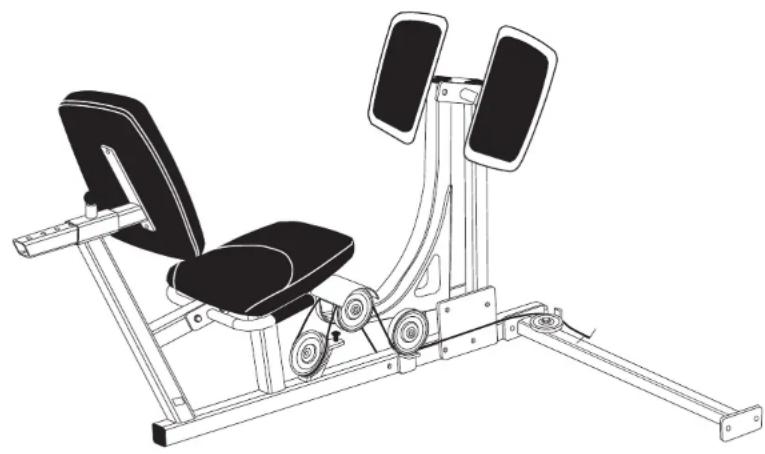
natural_image
Line drawing of a fitness exercise machine with two legs and side-mounted legs (no text or symbols)
Preparations
CAUTION: To set up this equipment, you will need assistance. Do not attempt assembly by yourself.
You must review and follow the instructions in this guide. If you do not assemble and use the Leg Press Option according to the following guidelines, you could void the Precor limited warranty.
Required Tools
You need to obtain these tools before assembling the unit:
☐3/4-inch socket wrench
^3 /4-inch box-end wrench
^9/16 -inch socket wrench
^9/16 -inch box-end wrench
☐Two adjustable pliers or crescent wrenches
☐Standard set of metric Allen wrenches
□Utility knife or scissors
□Measuring tape
Installation Requirements
Follow these installation requirements when assembling the unit:
- Fill out and mail the limited warranty card. The warranty card is found on the back cover of this guide.
- Set up the Leg Press Option on a solid, flat surface. A smooth, flat surface under the unit helps keep it level. A level unit has fewer malfunctions.
- Provide ample space around the machine. Open space around the machine allows for easier access.
- Insert all bolts in the same direction. For aesthetic purposes, insert all the bolts in the same direction unless specified (in text or illustrations) to do otherwise.
- Leave room for adjustments. Tighten fasteners such as bolts, nuts, and screws, so that the unit is stable, but leave room for adjustments. Do not fully tighten fasteners until instructed in the assembly steps to do so.
Assembly Tips
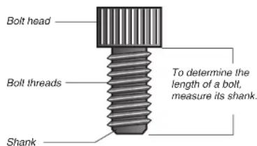
- A 6-inch scale is provided at the bottom of every assembly instruction page. Use this scale to identify the correct size bolts and spacers. The head of a bolt is not used in measuring the length of a bolt. To find out the length of a particular bolt, measure its shank (the long, narrow part beneath the head). Refer to the following diagram.
- Read all caution notes on each page before completing that step.
text_image
Bolt head Bolt threads Shank To determine the length of a bolt, measure its shank.- Some pieces have extra holes that you will not use. Use only those holes indicated in the instructions and illustrations.
- While you may be able to assemble the Leg Press Option by using the illustrations only, refer to the text for important safety cautions and notes.
3
Assembly Instructions
Assembly of the Leg Press Option takes professional installers about 1 hour to complete. If this is the first time you have assembled this type of equipment, plan on significantly more time.
Professional installers are highly recommended!
CAUTION: Obtain assistance! Do not attempt to assemble the Leg Press Option by yourself. Because of the weight and size of the Leg Press Option, you could be injured or damage the equipment. Review the Installation Requirements on page 5 before proceeding.
The Leg Press Option comes in one box. It can be installed on either the S3.25 or S3.45 Precor Strength Training Equipment. Note that the location where you attach the Cross Brace to the Seat Frame differs. As you read through the assembly instructions, be sure that you are using the correct mounting holes for your unit.
Be careful to assemble the components in the sequence presented in this guide.
Note: As with any assembled part, proper alignment and adjustment is critical. While tightening the fasteners, be sure to leave room for adjustments. Do not fully tighten the fasteners until instructed to do so.
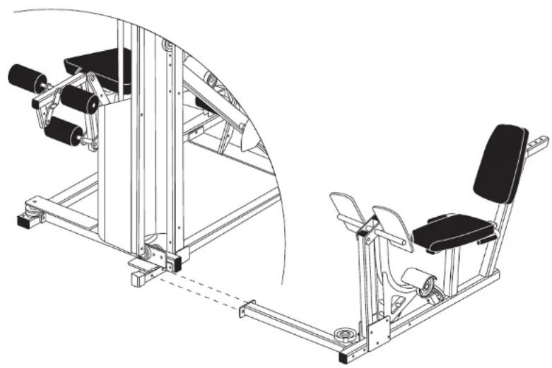
natural_image
Technical line drawing of a gym machine with side arm and seat assembly (no text or symbols)123456
Assembly Instructions
1. Remove the Shroud
Important: For ease of assembly, the fasteners and hardware for each step are labeled and packaged in separate bags.
Note: If you are assembling the Leg Press Option along with your S3.25, go directly to Step 2.
Before you can attach the Leg Press Option to the unit, you must remove the Shroud.
A. Remove the Shroud by loosening and removing six 2 ^3/4 -inch bolts
six washers
six locknuts
B. Pull the Shroud away from the S3.25 and lay it and its fasteners on the floor in a secure place.
Note: The top of the Shroud has a notch in it to help you clear the Top Beam fastener.
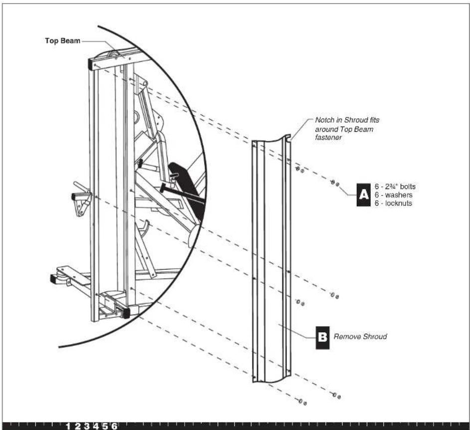
text_image
Top Beam Notch in Shroud fits around Top Beam fastener A 6 - 2¾" bolts 6 - washers 6 - locknuts B Remove Shroud 1 2 3 4 5 6Step 1. Remove the Shroud
2. Attach the Cross Brace to the \$3.25
Note: If you are assembling the Leg Press Option along with the S3.25, you should complete Step 10 in the S3.25 Assembly and Maintenance Guide before attaching the Cross Brace.
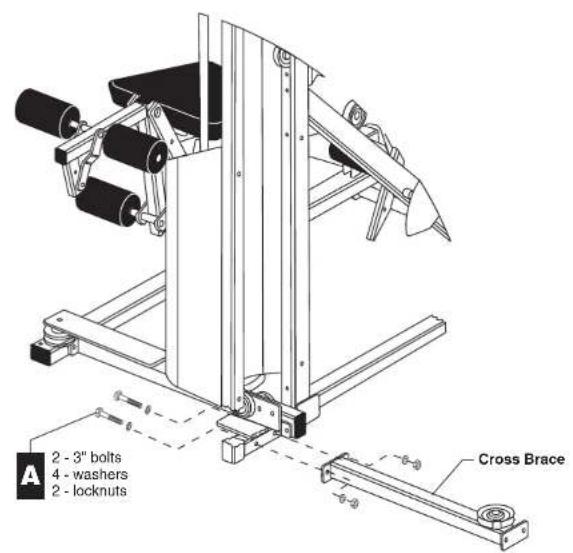
A. Align the Cross Brace to the S3.25 Rear Upright and secure it using two 3-inch bolts four washers two locknuts Wrench tighten.
text_image
A 2 - 3" bolts 4 - washers 2 - locknuts Cross Brace123456
Step 2. Attach the Cross Brace to the S3.25
3. Assemble the Frame
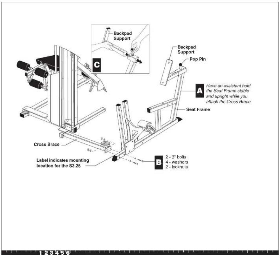
A. With someone helping you, lift the Seat Frame upright. Have your assistant hold it in place while you attach the Cross Brace in the next step.
B. Attach the Cross Brace to the holes found at the front of the Seat Frame using two 3-inch bolts
four washers
two locknuts
Wrench tighten.
Important: A label on the Seat Frame indicates the mounting holes you must use to attach the Cross Brace to the S3.25 Leg Press Option.
C. Slide the Backpad Support into the Seat Frame, locking it in place with the Pop Pin.
text_image
Backpad Support C Backpad Support Pop Pin A Have an assistant hold the Seat Frame stable and upright while you attach the Cross Brace Seat Frame Cross Brace Label indicates mounting location for the S3.25 B 2 - 3" bolts 4 - washers 2 - locknutsStep 3. Assemble the Frame
S3.25 Leg Press Option Assembly Instructions
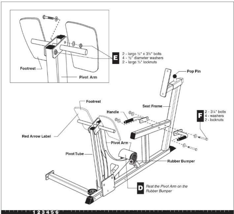
D. Assemble the Footrest by resting the Pivot Arm on the Rubber Bumper. Make sure that the red arrow on the back of the Footrest points toward the ceiling.
E. Attach the Footrest to the Pivot Arm and Pivot Tube using two large 12 -inch by 3- 14 -inch bolts four 12 -inch-diameter washers two large 12 -inch locknuts Wrench tighten enough to allow free movement of the Pivot Arm.
F. Attach the Handle to the Seat Frame using two 3¼-inch bolts
four washers
two locknuts
Wrench tighten.
text_image
Footrest Pivot Arm E 2 - large ½" x 3¼" bolts 4 - ½" diameter washers 2 - large ½" locknuts Pop Pin Footrest Red Arrow Label Handle Seat Frame Pivot Tube Rubber Bumper D Rest the Pivot Arm on the Rubber Bumper 2 - 3¼" bolts 4 - washers 2 - locknutsStep 3. Assemble the Frame, Continued
4. Assemble the Seat Pads
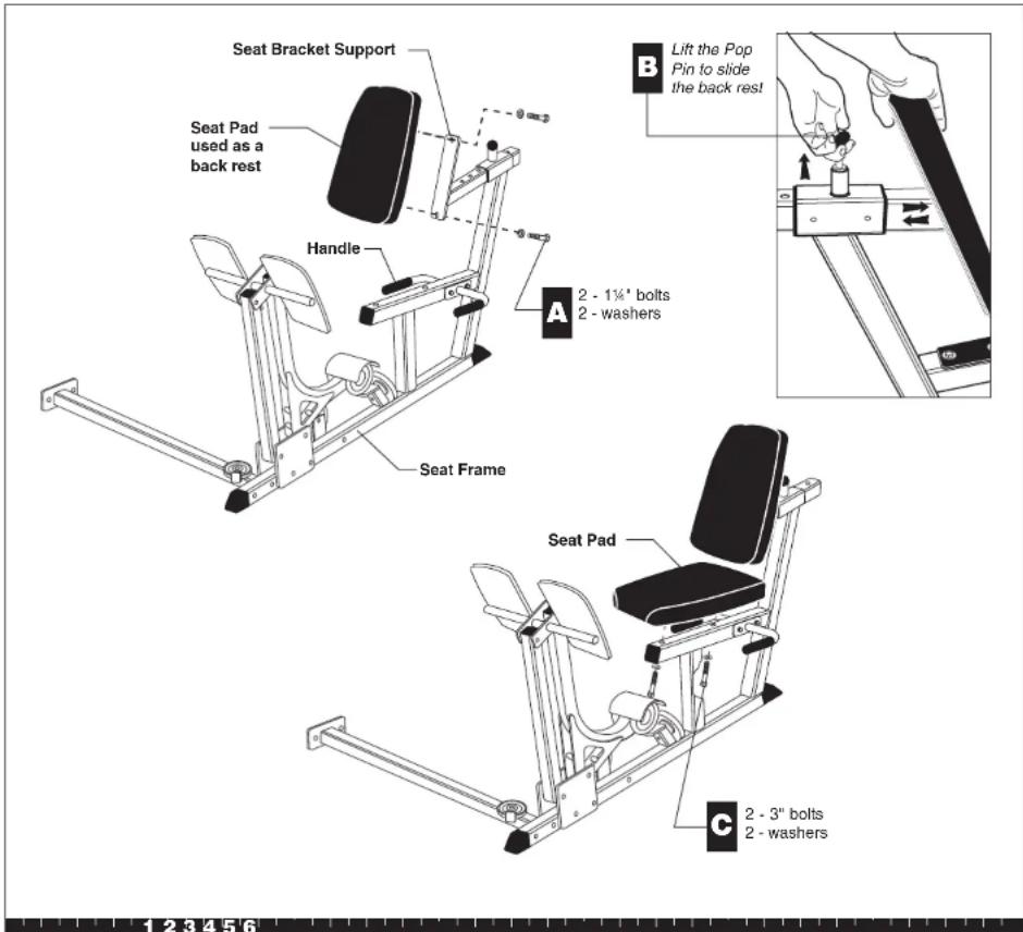
A. Attach one of the Seat Pads to the Seat Bracket Support using
two 1¼-inch bolts
two washers
Wrench tighten.
B. Lift the Pop Pin and slide the Seat Pad out of the way to assemble the other Seat Pad.
C. Attach the remaining Seat Pad to the Seat Frame using
two 3-inch bolts
two washers
Wrench tighten.
Note: Make sure that the seams on the Seat Pads face down toward the frame.
Note: If you are assembling the Leg Press Option and the S3.25 simultaneously, return to Step 11 in the
S3.25 Assembly and Maintenance Guide now.
text_image
Seat Bracket Support Seat Pad used as a back rest Handle A 2 - 1¼' bolts 2 - washers Seat Frame B Lift the Pop Pin to slide the back rest C 2 - 3" bolts 2 - washersStep 4. Assemble the Seat Pads
5. Route the Cable
As you route the Cable through the pulleys on the Leg Press Option, wrench tighten the fasteners on each pulley as you go. Make sure that the Cable slides freely along the pulley (and beneath the cable retainer). Make sure that you are using the correct Cable before you tighten the fasteners.
A. Attach the barrel end of Cable 40538-103 to the Seat Frame using one 4-inch bolt one washer one locknut Wrench tighten so that the barrel end of the Cable rotates freely.
B. Loosen all the fasteners that attach the pulleys to the Seat Frame.
C. Push the Pivot Arm forward so that the pulleys are easily accessible.
D. Route the Cable around the pulley inside the Pivot Arm Cover that is on the same side as the barrel end of the Cable (see illustration). The Cable should slide along the pulley beneath the cable retainer. Wrench tighten this pulley's fasteners.
E. You may need to slide the bolt out of the Pivot Arm Cover to wrap the Cable around the pulley.
F. Continue to route the Cable around the pulleys as shown in the illustration. Make sure that the Cable slides freely along the pulleys (and beneath the cable retainers) before you wrench tighten their fasteners.
G. Wrap the Cable around the 4½-inch pulley (and beneath its cable retainer) that is attached to the Cross Brace. Wrench tighten.
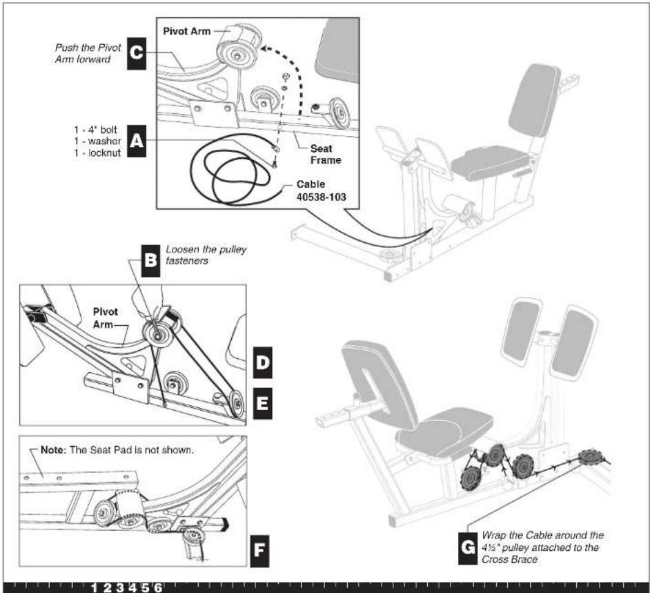
text_image
Push the Pivot Arm forward C Pivot Arm 1 - 4" bolt 1 - washer 1 - locknut A Seat Frame Cable 40538-103 B Loosen the pulley fasteners Pivot Arm D E Note: The Seat Pad is not shown. F G Wrap the Cable around the 4½" pulley attached to the Cross Brace 1 2 3 4 5 6Step 5. Route the Cable
6. Assemble the Cable and Pulleys
You can identify Cables by the white numbers placed at the end of the Cable.
A. Place Leg Press Option Cable 40538-103 between a cable retainer and one 3 12 -inch pulley. Attach the pulley to the Lower Pulley Bracket located at the base of the Rear Upright using one 2-inch bolt two washers one locknut Wrench tighten.
B. From the Top Beam, remove the surgical tube and its fasteners.
Note: Discard the fasteners
one 3¼-inch bolt
one one-inch barrel spacer
two washers
one locknut
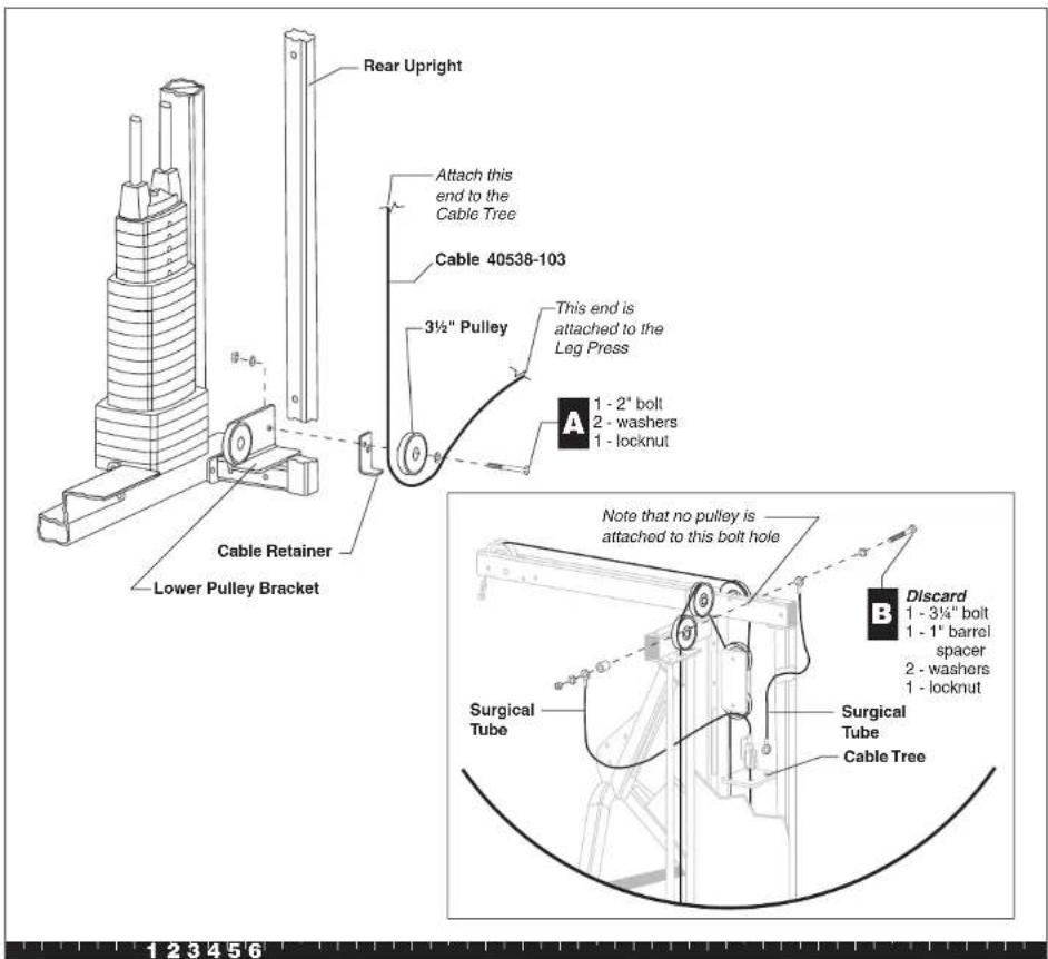
text_image
Rear Upright Attach this end to the Cable Tree Cable 40538-103 3½" Pulley This end is attached to the Leg Press A 1 - 2" bolt 2 - washers 1 - locknut Cable Retainer Lower Pulley Bracket Note that no pulley is attached to this bolt hole Discard 1 - 3¼" bolt 1 - 1" barrel spacer 2 - washers 1 - locknut Surgical Tube Surgical Tube Cable Tree 1 2 3 4 5 6Step 6. Assemble the Cable and Pulleys
S3.25 Leg Press Option Assembly Instructions
C. Reattach the end of the original Surgical Tube from the Cable Tree to its prior location and place the new Surgical Tube that came with the Leg Press Option to the outside of the Top Beam using one 4-inch bolt
two washers
two 12 -inch barrel spacers
one locknut
Wrench tighten.
D. Place the ball-end of Leg Press Option Cable 40538-103 up through the Cable Tree and place it securely in the U-clip.
E. Remove the buttonhead bolt and nylock nut from the U-clip.
F. Attach the end of the original surgical tube to the Cable Tree using the 1¼-inch buttonhead bolt and thin nylock nut removed in Step 6E. Wrench tighten.
Note: If you are assembling the Leg Press Option and the S3.25 simultaneously, go to Step 21 in the S3.25 Assembly and Maintenance Guide now.
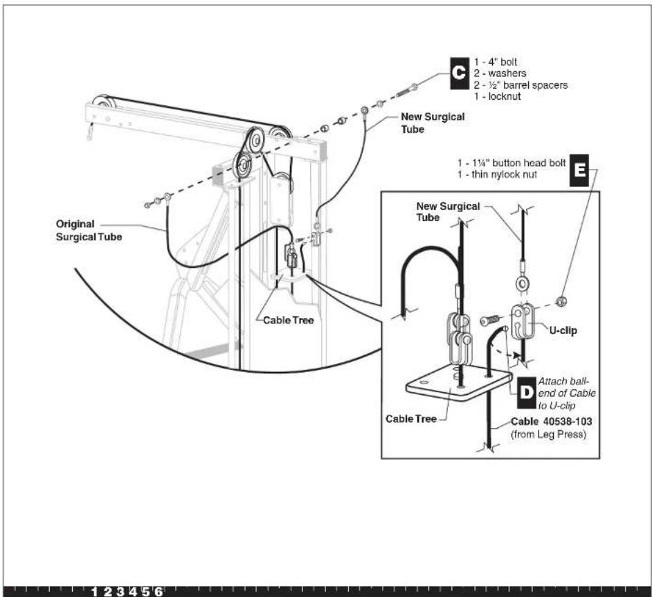
text_image
Original Surgical Tube Cable Tree New Surgical Tube 1 - 4" bolt 2 - washers 2 - ½" barrel spacers 1 - locknut 1 - 1¼" button head bolt 1 - thin nylock nut New Surgical Tube U-clip Cable Tree Attach ball-end of Cable to U-clip Cable 40538-103 (from Leg Press) 1 2 3 4 5 6Step 6. Assemble the Cable and Pulleys, Continued
7. Replace the Shroud
A. Pick up the Shroud and fasteners from the location where you left them in Step 4B.
B. Replace the Shroud by realigning the mounting holes and inserting six 2¾-inch bolts six washers six locknuts Wrench tighten.
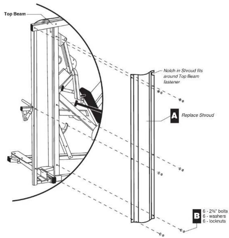
text_image
Top Beam A Replace Shroud Notch in Shroud fits around Top Beam fastener B 6 - 2¼" bolts 6 - washers 6 - locknuts123456
Step 7. Replace the Shroud

Adjustments
After the Leg Press Option is assembled, you should check the Cables for proper tension. These are some obvious signs that cable problems exist:
√Excess slack exists in the Cable.
√The Top Cap Weight does not rest squarely on the Weight Stack.
√The Cable rubs the inside edges of the pulleys.
CAUTION: Take the time to perform the following steps. If the Cables do not have the proper tension, you could damage the machine and void the Precor Limited Warranty.
Note: To adjust the Selector Stem, refer to the S3.25 Assembly and Maintenance Guide.
1. Stretch the Cable
A. Sometimes a new cable must be stretched so that the Top Cap Weight rests on the Weight Stack. To lengthen the Cable, insert the Weight Pin at a comfortable weight level.
B. Push up on the Chest Press Arms, and then slowly lower them.
C. Make sure the Top Cap Weight rests squarely on the Weight Stack. If it does, no more adjustments are needed, and the Leg Press Option is ready to use. If the Top Cap Weight does not rest on the Top Weight then further adjustments are needed. Continue with steps 2 and 3.
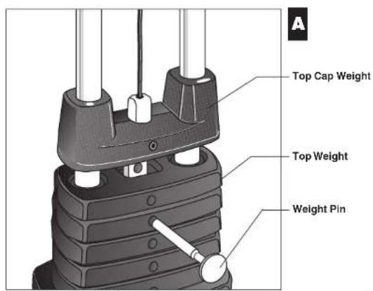
text_image
A Top Cap Weight Top Weight Weight Pin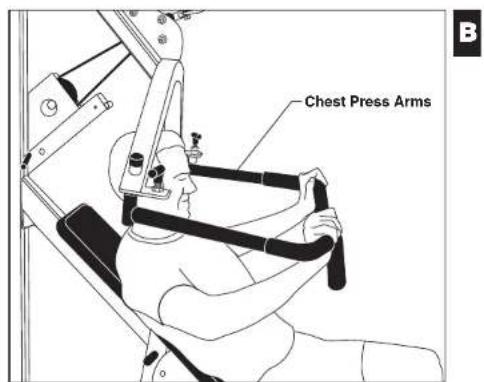
text_image
Chest Press Arms B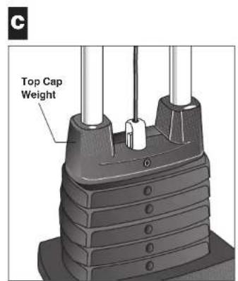
text_image
C Top Cap Weight123456
Adjustments
2. Rotate the Cam Washer
If the Top Cap Weight does not rest on the Top Weight, you must make further adjustments.
A. Remove excess tension from the Cable by placing the Weight Pin into the Selector Stem just under the Top Cap Weight.
B. To tighten or loosen the Cable tension, rotate the Cam Washer.
C. Look to see that Top Cap Weight rests squarely on the Weight Stack. If it does, no more adjustments are needed and the Leg Press Option is ready to use. If the Top Cap Weight does not rest on the Top Weight, then further adjustments are needed. Continue with step 3.
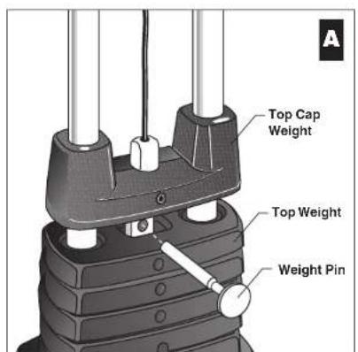
text_image
Top Cap Weight Top Weight Weight Pin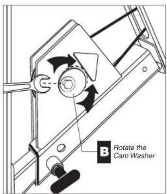
text_image
B Rotate the Cam Washer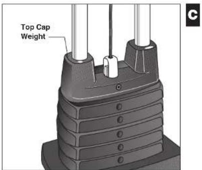
text_image
Top Cap Weight123456
Step 2. Rotate the Cam Washer
3. Adjust the Rubber Bumper on the Leg Press Option
If the Top Cap Weight still does not rest on the Top Weight, you can make one final adjustment.
A. If the Cable tension still needs adjusting, push the Pivot Arm up so that you can adjust the Rubber Bumper on the Leg Press Option.
B. Rotate the Rubber Bumper up or down to tighten or loosen the Cable tension.
Important: Tighten the locknut against the bracket after you have properly adjusted the Cable tension.
C. Check the weights. Move the Weight Pin to each Weight and Selector Stem location and replace the Weight Pin in the Weight Stack.
With the slack removed from the Cables, you are now ready to use the Leg Press Option. Thank you for choosing Precor Strength-Training Equipment.
Note: For maintenance instructions, refer to your S3.25 Assembly and Maintenance Guide.
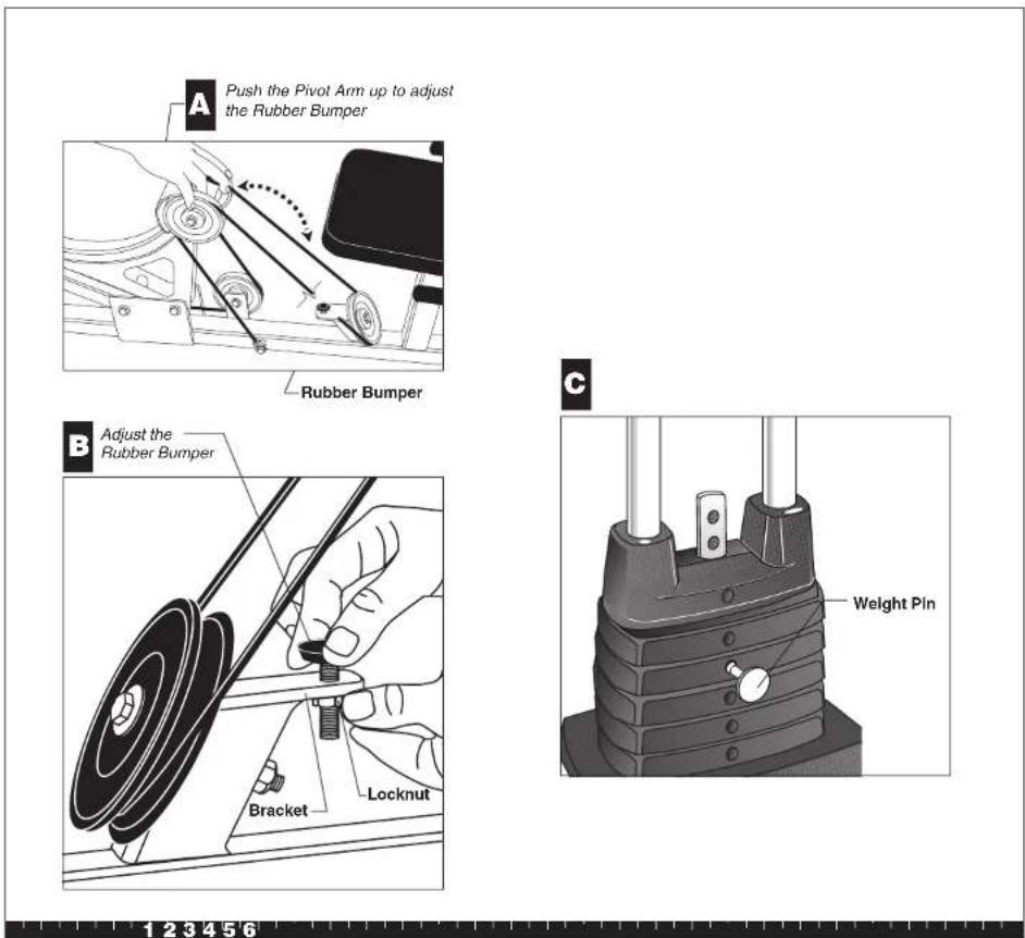
Step 3. Adjust the Rubber Bumper on the Leg Press Option
Thank You and Welcome to Precor
PRECOR USA
move beyond®
To allow us to serve you better, please take a few moments to complete and return your warranty registration.
www.precor.com/warranty
YOU MAY ALSO REGISTER ONLINE AT
If you have questions or need additional information, contact your local dealer or call Precor Customer Support at 800-347-4404.
Fold along dotted line and tape closed before mailing.
RE
PRECOR USA 20031 142nd Avenue PO Box 7202 Woodville, WA 98
PLACE
STAMP
383H
□Physician recommendation
□Warranty
□Quality/durability
URebate or sale price
□Special product tea
☐ Value for the price
Design/appearance
□ Prior use of Precoi
□ Precor reputation
purchase your Precor product (choose up to three):
What factors MOST influenced your decision to
[Non-Text]
[Non-Text]
☐ Addition to equipment currently owned
□ Replaces same type of product – different brand
□ Replaces a Precor product of the same type
□ First Processor product
Purchase (check all that apply):
TELL US ABOUT YOUR PURCHASE
OTHER
In-store display or demonstration
J Print advertisement
□ Magazine advertisement or an
□ News report or product review
Internet
□Fitness club
Physician
□ Friend/relative
A gth
How did you FIRST become aware of Precor products (choose only one):
October
Rehabilitation
UStress reduction
□ Increase energy and flexibility
Overall health
☐ Cardiovascular Improvement
Muscle tone enhancement
□ Weight loss/management
what are your fitness goals?
6.1.1.2.3.4.5.6.7.8.9.10.11.12.13.14.15.16.17.18.19.20.21.22.23.24.25.26.27.28.29.30.31.32.33.34.35.36.37.38.39.40.41.42.43.44.45.46.47.48.49.50.51.52.53.54.55.56.57.58.59.60.61.62.63.64.65.66.67.68.69.70.71.72.73.74.75.76.77.78.79.80.81.82.83.84.85.86.87.88.89.90.91.92.93.94.95.96.97.98.99.100
[Non-Text]
| | | | | | | |
The Ground Truth image displays a single, solid horizontal line, which is a stylistic or background element (like a rule line on paper). According to Rule 2, such lines must be ignored by the OCR result. The provided OCR content is "____", which consists of underscores. Underscores are not equivalent to a solid line and are not permitted under the “Stylistic/Background Lines (Ignore)” rule. Outputting underscores for a stylistic line is incorrect because it misinterprets the line as a placeholder fill-in-the-blank area. Since the OCR output incorrectly rendered underscores for a stylistic line, this violates the rule. Therefore, the OCR result is inconsistent with the Ground Truth.
(1) AD = BD = 1, 故 AB = AC = 0 ,故 AC = DE = 1
[Non-Text]
| | | | | | | | |
The Ground Truth image displays a single, solid horizontal line. According to Rule 2 (UNDERSCORE & LINE RULES), this is a stylistic or background line, not a placeholder underscore. Therefore, the OCR result must ignore it and output nothing or only meaningful text. The provided OCR content is "____", which consists of four underscores. This is an incorrect interpretation of the line as a placeholder, violating the rule that stylistic lines must be ignored. The OCR has hallucinated underscores where none should exist based on the GT's visual context. Hence, the OCR result is inconsistent with the Ground Truth.
[Non-Text]
[EMPTY]
[Non-Text]
[Non-Text]
[Non-Text]
[Non-Text]
[Non-Text]
[Non-Text]
The Ground Truth image displays a single, solid horizontal line, which is a stylistic or background element (like a rule line on paper). According to Rule 2, such lines must be ignored by the OCR result. The provided OCR content is "____", which consists of underscores. Underscores are not equivalent to a solid line and are not permitted under the “Stylistic/Background Lines (Ignore)” rule. Outputting underscores for a solid line constitutes an error, as it misrepresents the visual element and violates the instruction to ignore stylistic lines. Therefore, the OCR result is inconsistent with the Ground Truth.
(No text)
TELL US ABOUT YOUR NEW PRECER PRODUCT
Precor Residential Equipment Limited Warranty
PLEASE READ THESE WARRANTY TERMS AND CONDITIONS CAREFULLY BEFORE USING YOUR PRECOR INCORPORATED PRODUCT. BY USING THE EQUIPMENT, YOU ARE CONSENTING TO BE BOUND BY THE FOLLOWING WARRANTY TERMS AND CONDITIONS.
Limited Warranty.
Precor Incorporated warrants all new Precor products to be free from defects in materials and manufacture for the warranty period set forth below. The warranty period commences on the invoice date of original purchase. This warranty applies only against defects discovered within the warranty period and extends only to the original purchaser of the product. Parts repaired or replaced under the terms of this warranty will be warranted for the remainder of the original warranty period only. To make claim under warranty, the buyer must notify Precor or their authorized Precor dealer within 30 days after the date of discovery of any nonconformity and make the affected product available for inspection by Precor or its service representative. Precor's obligations under this warranty are limited and set forth below.
Warranty Periods and Coverage
All residential products and commercial products used in the home are warranted for the following periods:
• Lifetime frame and welds
• 10 years parts and wear items
• 1 year labor
- Coverage for options and accessories defined below.
Options / Accessories
Many options or accessories have components that are connected internally or mounted inside the electronic console. The following guidelines determine the warranty for these components. If the internal components are installed by the factory or by an authorized dealer as part of the original sale and delivery, they have a warranty that is identical to the warranty of the equipment in which they are connected or mounted. If the internal components are not installed by the factory or by an authorized dealer as part of the original sale and delivery, they have a 90-day parts and labor limited warranty. All components that are not internally connected have 90-day parts only limited warranty. Satisfactory proof of purchase is required in all cases.
Conditions and Restrictions
This warranty is valid only in accordance with the conditions set forth below:
- The warranty applies to the Precor product only while:
a. It remains in the possession of the original purchaser and proof of purchase is demonstrated
b. It has not been subjected to accident, misuse, abuse, improper service, or non-Precor modifications
c. Claims are made within the warranty period
- This warranty does not cover damage or equipment failure caused by electrical wiring not in compliance with electrical codes or Precor owner's manual specifications, or failure to provide reasonable and necessary maintenance as outlined in the owner's manual.
Complete this portion and keep for your records.
| Purchased From: | Example: Dealer or store name. |
| Phone Number: | Example: Dealer or store telephone number. |
| Product/model: | Example: M9.31 |
| Serial number: | The serial number is found on the shipping container |
- Warranty of all Precor products applies to residential use only and is void when products are used in a nonresidential environment or installed in a country other than where sold.
- Except in Canada, Precor does not pay labor outside the United States.
- Warranties outside the United States and Canada may vary. Please contact your local Dealer for details.
This limited warranty shall not apply to:
- Software version upgrades
- Cosmetic items, including, but not limited to the following: grips, seats, and labels.
- Repairs performed on Precor equipment missing a serial number or with a serial tag that has been altered or defaced.
- Service calls to correct installation of the equipment or instruct owners on how to use the equipment.
- Pickup, delivery, or freight charges involved with repairs.
- Any labor costs incurred beyond the applicable labor warranty period.
Disclaimer and Release
The warranties provided herein are the exclusive warranties given by Precor and supersede any prior, contrary or additional representations, whether oral or written. ANY IMPLIED WARRANTIES. INCLUDING THE WARRANTY OF MERCHANTABILITY OR FITNESS FOR A PARTICULAR PURPOSE THAT APPLY TO ANY PARTS DESCRIBED ABOVE ARE LIMITED IN DURATION TO THE PERIODS OF EXPRESS WARRANTIES GIVEN ABOVE FOR THOSE SAME PARTS. PRECOR HEREBY DISCLAIMS AND EXCLUDES THOSE WARRANTIES THEREAFTER. Some states do not allow limitation on how long an implied warranty lasts, so the above limitation may not apply to you. PRECOR ALSO HEREBY DISCLAIMS AND EXCLUDES ALL OTHER OBLIGATIONS OR LIABILITIES, EXPRESS OR IMPLIED, ARISING BY LAW OR OTHERWISE, WITH RESPECT TO ANY NONCONFORMANCE OR DEFECT IN ANY PRODUCT. INCLUDING BUT NOT LIMITED TO: (A) ANY OBLIGATION, LIABILITY, RIGHT, CLAIM OR REMEDY IN TORT, WHETHER OR NOT ARISING FROM THE NEGLIGENCE OF PRECOR OR ITS SUPPLIERS (WHETHER ACTIVE, PASSIVE OR IMPUTED); AND (B) ANY OBLIGATION, LIABILITY, RIGHT, CLAIM, OR REMEDY FOR LOSS OF OR DAMAGE TO ANY EQUIPMENT. This disclaimer and release shall apply even if the express warranty set forth above fails of its essential purpose.
Exclusive Remedies
For any product described above that falls to conform to its warranty, Precor will provide, at their option, one of the following: (1) repair; (2) replacement; or (3) refund of the purchase price. Precor Limited Warranty service may be obtained by contacting the authorized dealer from whom you purchased the item. Precor compensates Servicers for warranty trips within their normal service area to repair equipment at the owner's location. You may be charged a trip charge outside the service area. THESE SHALL BE THE SOLE AND EXCLUSIVE REMEDIES OF THE BUYER FOR ANY BREACH OF WARRANTY.
Exclusion of Consequential and Incidental Damages
PRECOR AND/OR ITS SUPPLIERS SHALL HAVE NO OBLIGATION OR LIABILITY, WHETHER ARISING IN CONTRACT (INCLUDING WARRANTY), TORT (INCLUDING ACTIVE, PASSIVE, OR IMPUTED NEGLIGENCE AND STRICT LIABILITY), OR OTHERWISE, FOR DAMAGE TO THE EQUIPMENT, PROPERTY DAMAGE, LOSS OF USE, REVENUE OR PROFIT, COST OF CAPITAL, COST OF SUBSTITUTE EQUIPMENT, ADDITIONAL COST INCURRED BY BUYER (BY WAY OF CORRECTION OR OTHERWISE) OR ANY OTHER INCIDENTAL, SPECIAL, INDIRECT, OR CONSEQUENTIAL DAMAGES, WHETHER RESULTING FROM NONDELIVERY OR FROM THE USE, MISUSE OR INABILITY TO USE THE PRODUCT. This exclusion applies even if the above warranty fails of its essential purpose and regardless of whether such damages are sought for breach of warranty, breach of contract, negligence, or strict liability in tort or under any other legal theory. Some states do not allow the exclusion or limitation of incidental or consequential damages, so the above limitation might not apply.
This warranty gives you specific legal rights, and you may also have other rights, which vary state to state.
Effective 01 January 2003
P/N 36287-110
S3.25 Leg Press Option Specifications
Length: 60 inches (152 cm)
Height: 33 inches (84 cm)
Width: 30 inches (76 cm)
Shipping weight: 125 lb (57 kg)
PRECOR USA
Precor Incorporated
20031 142nd Avenue NE
P.O. Box 7202
Woodinville, WA USA 98072-4002
Precor and Pacific Fitness are registered trademarks of Precor Incorporated.
Specifications subject to change without notice.
Copyright 2005 Precor Incorporated.
Precor web site: www.precor.com
NOTICE:
Precor is widely recognized for its innovative, award winning designs of exercise equipment. Precor aggressively seeks U.S. and foreign patents for both the mechanical construction and the visual aspects of its product design. Any party contemplating the use of Precor's product designs is hereby forewarned that Precor considers the unauthorized appropriation of its proprietary rights to be a very serious matter. Precor will vigorously pursue all unauthorized appropriation of its proprietary rights.
S3.25 LPO Literature Kit # 47942-104
Leg Press Assembly Instructions # 47989-104
Warranty Registration # 45623-102
Warranty Card # 36287-110
Effective date: 22 April, 2005