HRT4-B - Thermostat Horstmann - Free user manual and instructions
Find the device manual for free HRT4-B Horstmann in PDF.


User questions about HRT4-B Horstmann
0 question about this device. Answer the ones you know or ask your own.
Ask a new question about this device
Download the instructions for your Thermostat in PDF format for free! Find your manual HRT4-B - Horstmann and take your electronic device back in hand. On this page are published all the documents necessary for the use of your device. HRT4-B by Horstmann.
USER MANUAL HRT4-B Horstmann
natural_image
Gray rectangular object with a central white circle and eight rounded rectangular cutouts (no text or symbols)HORSTMANN
HRT4-B User and Installation Instructions
Battery Operated Electronic Room Thermostat with TPI temperature control software

natural_image
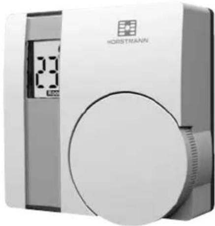
Exterior view of a Horstmann digital water heater with LCD display and circular button (no text or symbols on main body)The HRT4-B is a battery powered electronic room thermostat designed to provide optimum comfort with close control of the energy used to heat the home.
The HRT4-B will only operate when 2 x AAA batteries have been fitted and the thermostat is wired into your central heating system.
INSTALLATION AND CONNECTION OF THE HRT4-B MUST BE CARRIED OUT BY A SUITABLY QUALIFIED PERSON.
WARNING: ISOLATE MAINS SUPPLY BEFORE COMMENCING INSTALLATION.
For the user
What is a room thermostat? ... an explanation for householders
A room thermostat simply switches the heating system on and off as necessary. It works by sensing the air temperature, switching on the heating when the air temperature falls below the thermostat setting, and switching it off once this set temperature has been reached.
Turning a room thermostat to a higher setting will not make the room heat up any faster. How quickly the room heats up depends on the design of the heating system, for example, the size of boiler and radiators.
Neither does the setting affect how quickly the room cools down. Turning a room thermostat to a lower setting will result in the room being controlled at a lower temperature, and saves energy.
The heating system will not work if a time switch or programmer has switched it off.
The way to set and use your room thermostat is to find the lowest temperature setting that you are comfortable with, and then leave it alone to do its job. The best way to do this is to set the room thermostat to a low temperature - say 18°C - and then turn it up by one degree each day until you are comfortable with the temperature. You won't have to adjust the thermostat further. Any adjustment above this setting will waste energy and cost you more money.
If your heating system is a boiler with radiators, there will usually be only one room thermostat to control the whole house. But you can have different temperatures in individual rooms by installing thermostatic radiator valves (TRVs) on individual radiators. If you don't have TRVs, you should choose a temperature that is reasonable for the whole house. If you do have TRVs, you can choose a slightly higher setting to make sure that even the coldest room is comfortable, then prevent any overheating in other rooms by adjusting the TRVs.
Room thermostats need a free flow of air to sense the temperature, so they must not be covered by curtains or blocked by furniture. Nearby electric fires, televisions, wall or table lamps may prevent the thermostat from working properly.
Additional User information
The Horstmann HRT4-B thermostat uses the latest control technology to provide extremely accurate temperature control which will help to keep your energy usage as low as possible without affecting your comfort levels. In fact comfort levels may well be improved as the control accuracy should ensure that the room does not ‘overheat’ before switching off.
User Instructions
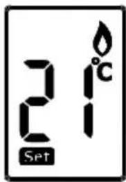
The display will show the required temperature setting and can be adjusted in increments of 1^ C.
To adjust the required temperature setting turn the dial anti clockwise to decrease it and clockwise to increase it.
natural_image
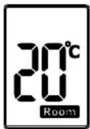
Exterior view of a modern office building (no signage)Pressing the temperature setting dial will allow the user to check the current room temperature which will be displayed for approx 7 seconds before returning to the set temperature.
text_image
21°C SetWhen the thermostat is in the 'call for heat' condition a flame symbol will appear in the display.
text_image
20°C RoomFurther information on how the thermostat operates is contained in the 'Explanation for householders' that precedes this section.
Battery replacement
The HRT4-B runs on 2 x type AAA (Alkaline) non rechargeable batteries and is designed to give a battery life of approximately two years.
text_image
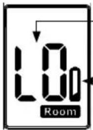
1.0 RoomBatteries should be changed immediately
Low battery symbol appears first when the batteries are nearing the end of their life
When the batteries are nearing the end of their life a low battery symbol will appear in the display and the batteries should be changed within a few days. If the batteries are not changed at this point eventually a 'LO' battery message flashes intermittently in the display and if this happens the batteries should be changed immediately.
To change the batteries it is necessary to remove the thermostat from the wall.
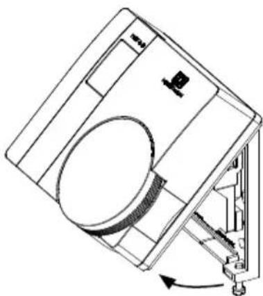
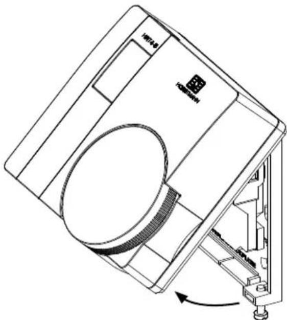
To do this first undo the two captive screws at the base of the thermostat and swing the thermostat up and away from the wall plate.
N.B. The wall plate must not be altered or modified as it has been specially designed to isolate the mains supply when the thermostat is removed to change the batteries.
Remove the old batteries and replace them with two new AAA size alkaline batteries ensuring that they are fitted correctly as indicated by the terminal markings in the battery compartments.
Please dispose of the batteries responsibly.

natural_image
Technical line drawing of a mechanical device with a circular component and directional arrow (no text or symbols)Once the batteries are fitted, re-fit the thermostat to the wall plate by engaging with the lugs at the top of the wall plate and push the thermostat into position. Locate it over the captive screws at the base of the wall plate and tighten so that the thermostat is locked into position.
Check the temperature setting is correct and adjust if necessary.
Installation Instructions
Warning isolate mains supply before commencing installation.
Positioning the Room Thermostat
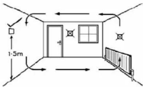
The HRT4-B should be mounted on an internal wall approximately 1.5 metres from floor level and should be in a position away from draughts, direct heat and sunlight. Ensure that there will be enough space to allow easy access to the two retaining screws located at the base of the wall plate.
text_image
1:5mFitting the wall plate
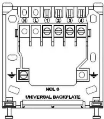
To remove the wall plate from the HRT4-B undo the two retaining screws located on the underside, the wall plate should now be easily removed. Once the wall plate has been removed from the packaging please ensure the HRT4-B is re-sealed to prevent damage from dust, debris etc.
The wall plate should be fitted with the wiring terminals located at the top and in a position which allows a total clearance of at least 50mm around the HRT4-B thermostat.
text_image
HCL 6 UNIVERSAL BACKPLATEDirect Wall Mounting
Offer the plate to the wall in the position the HRT4-B is to be mounted and mark the fixing positions through the slots in the wall plate. Drill and plug the wall, then secure the plate in position. The slots in the wall plate will compensate for any misalignment of the fixings.
Wiring Box Mounting
The HRT4-B wall plate may be fitted directly on to a single gang steel flush wiring box complying with BS4662, using two M3.5 screws. The HRT4-B is suitable for mounting on a flat surface only; it must not be positioned on an unearthed metal surface.
Electrical Connections
All necessary electrical connections should now be made. Flush wiring can enter from the rear through the aperture in the wall plate. For mains voltage applications a 3 Amp fused spur should be used. The recommended cable size is 1.0mm ^2 .
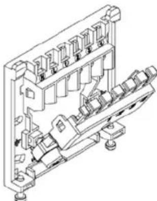
The wall plate is provided with a terminal guard to protect the user when replacing the batteries. This is supplied with the wall plate and it is essential that the terminal guard is fitted after completing the electrical connections to the terminals of the wall plate.
natural_image
Technical line drawing of an electrical connector assembly (no text or symbols)FAILURE TO DO THIS COULD RESULT IN ELECTRIC SHOCK WHEN CHANGING BATTERIES.
As access to the terminals will not be possible once the terminal guard is fitted only fit the guard when all wiring is complete and the system checked for correct operation.
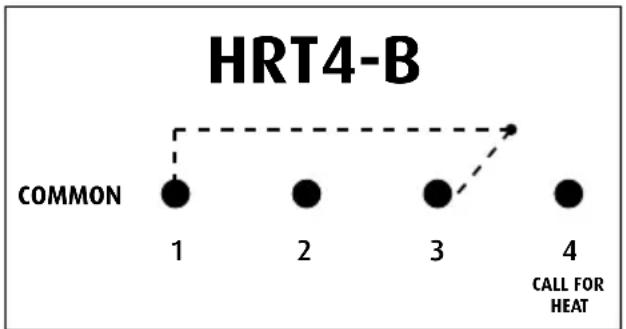
HRT4-B thermostat – internal wiring diagram
The HRT4-B is double insulated and does not require an earth connection, an earth connection block is provided on the wall plate for terminating any cable earth conductors. Earth continuity must be maintained and all bare earth conductors must be sleeved. Ensure that no conductors are left protruding outside the central space enclosed by the wall plate.
flowchart
graph TD
    A["COMMON"] --> B["1"]
    A --> C["2"]
    A --> D["3"]
    A --> E["4"]
    style A fill:#000,stroke:#000,color:#fff
    style B fill:#000,stroke:#000,color:#fff
    style C fill:#000,stroke:#000,color:#fff
    style D fill:#000,stroke:#000,color:#fff
    style E fill:#000,stroke:#000,color:#fff
- The HRT4-B has voltage free contacts.
- The HRT4-B is battery powered, therefore no mains connection is required to power it.
Please ensure that all wiring complies with the current IEE regulations.
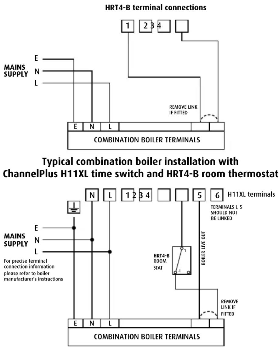
Typical combination boiler installation for boiler with built in timer and external room 'stat
text_image
HRT4-B terminal connections 1 2 3 4 E N L E N L REMOVE LINK IF FITTED COMBINATION BOILER TERMINALS Typical combination boiler installation with ChannelPlus H11XL time switch and HRT4-B room thermostat E N L 1 2 3 4 5 6 H11XL terminals E N L 1 2 3 4 5 6 MAINS SUPPLY E N L For precise terminal connection information please refer to boiler manufacturer's instructions HRT4-B ROOM STAT TERMINALS L-5 SHOULD NOT BE LINKED E N L BOILER LIVE OUT REMOVE LINK IF FITTED COMBINATION BOILER TERMINALSThese diagrams are schematic and should be used for guidance only.
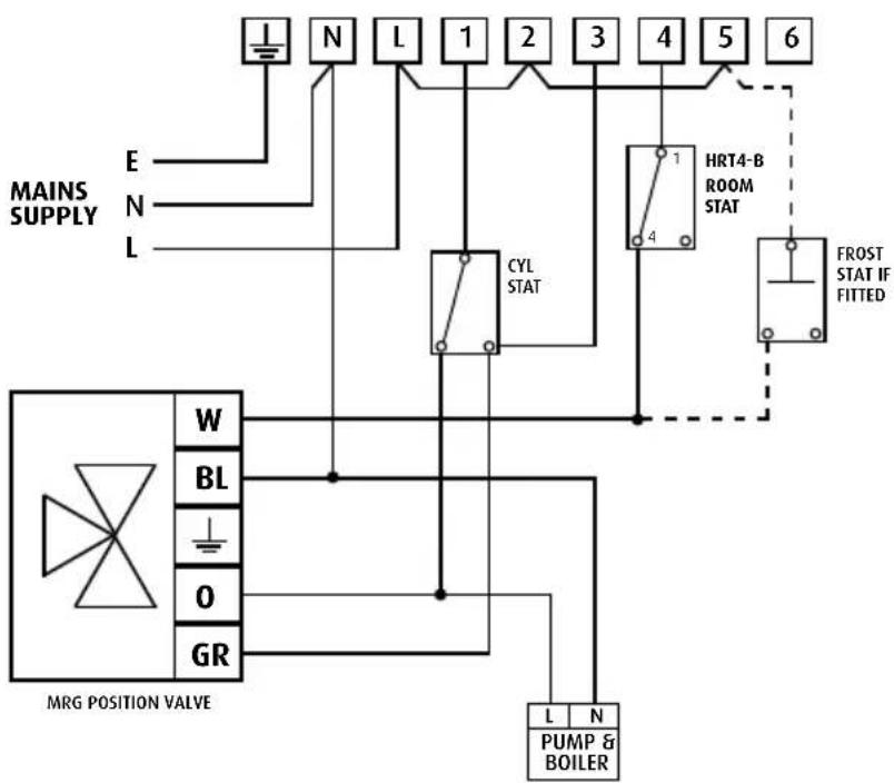
Fully Pumped Heating System using HRT4-B room stat, cylinder stat and Three Port Mid Position Valve with a Horstmann ChannelPlus H21/H27 electronic programmer.
flowchart
graph TD
    A["MAINS SUPPLY"] --> B["E"]
    A --> C["N"]
    A --> D["L"]
    B --> E["CYL STAT"]
    C --> E
    D --> E
    E --> F["HRT4-B ROOM STAT"]
    F --> G["FROST STAT IF FITTED"]
    G --> H["PUMP & BOILER"]
    I["MRG POSITION VALVE"] --> J["W"]
    I --> K["BL"]
    I --> L["O"]
    I --> M["GR"]
    J --> N["L"]
    K --> N
    L --> N
    M --> N
    N --> O["N"]
    style I fill:#f9f,stroke:#333
    style J fill:#ccf,stroke:#333
    style K fill:#ccf,stroke:#333
    style L fill:#ccf,stroke:#333
    style M fill:#ccf,stroke:#333
    style N fill:#ccf,stroke:#333
    style O fill:#ccf,stroke:#333
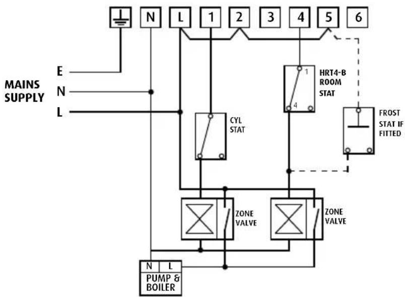
Fully Pumped Heating System using HRT4-B room stat, cylinder stat and Two (2 Port) Spring Return Valves with auxiliary switches and a Horstmann ChannelPlus H21/H27 electronic programmer.
flowchart
graph TD
    A["Main Supply"] --> B["N"]
    B --> C["L"]
    C --> D["1"]
    D --> E["2"]
    E --> F["3"]
    F --> G["4"]
    G --> H["5"]
    H --> I["6"]
    J["E"] --> K["L"]
    L["N"] --> M["L"]
    N["MAINS SUPPLY"] --> O["CYL STAT"]
    P["N"] --> Q["ZONE VALVE"]
    R["L"] --> S["ZONE VALVE"]
    T["HRT4-B ROOM STAT"] --> U["1"]
    U --> V["4"]
    W["FROST STAT IF FITTED"] --> X["Ground"]
    Y["PUMP & BOILER"] --> Z["N L"]
    style A fill:#f9f,stroke:#333
    style B fill:#ccf,stroke:#333
    style C fill:#cfc,stroke:#333
    style D fill:#fcc,stroke:#333
    style E fill:#cff,stroke:#333
    style F fill:#ffc,stroke:#333
    style G fill:#cfc,stroke:#333
    style H fill:#fcc,stroke:#333
    style I fill:#ffc,stroke:#333
    style J fill:#cfc,stroke:#333
    style K fill:#fcc,stroke:#333
    style L fill:#cfc,stroke:#333
    style M fill:#fcc,stroke:#333
    style N fill:#cfc,stroke:#333
    style O fill:#fcc,stroke:#333
    style P fill:#cfc,stroke:#333
    style Q fill:#fcc,stroke:#333
    style R fill:#cfc,stroke:#333
    style S fill:#fcc,stroke:#333
    style T fill:#cfc,stroke:#333
    style U fill:#fcc,stroke:#333
    style V fill:#cfc,stroke:#333
    style W fill:#fcc,stroke:#333
    style X fill:#cfc,stroke:#333
INSTALLATION AND CONNECTION OF THE HRT4-B MUST BE CARRIED OUT BY A SUITABLY QUALIFIED PERSON. WARNING: ISOLATE MAINS SUPPLY BEFORE COMMENCING INSTALLATION.
These diagrams are schematic and should be used for guidance only.
Fitting the thermostat to the wall plate
Ensure the terminal guard is fitted into place over the terminals of the wall plate. Fit the two AAA batteries provided, ensuring they are installed correctly as indicated by the terminal markings in the battery compartment. Ensure that the electricity supply to the HRT4-B is switched OFF.
Swing the thermostat into position on the wall plate without fitting the battery terminal guard. Tighten the 2 captive screws on the underside of the unit.
Now switch ON the electrical circuit to the HRT4-B and observe that it switches the heating system On and Off as the temperature is turned up and down on the thermostat. If the thermostat is switching the heating system satisfactorily then switch the electricity supply to the thermostat OFF, remove the thermostat from the wall plate and fit the terminal guard over the terminals on the wall plate.
natural_image
Technical line drawing of a mechanical device with internal components and a rotating arrow (no text or symbols)Once clipped into position the terminal guard cannot be removed from the wall plate.
Re-fit the thermostat into position on the wall plate and tighten the 2 captive screws on the underside of the unit. Switch on the electricity supply to the HRT4-B and check again for correct operation.
Explain its operation to the householder before handing over these instructions, highlighting the 'explanation for householders' section on page 2.
Wiring conversion charts Replacing existing Horstmann thermostats
| HRT4-B DRT1 |
| Common 1 Common |
| Call (N/O) 4 N/O |
| Satisfied (N/C) 3 N/C |
Replacing other thermostats
| HRT4-B Drayton Danfoss Honeywell Digistat + RETB DT90E | ||
| Common 1 Com 3 A | ||
| Call (N/O) 4 On 2 B | ||
| Satisfied(N/C) 3 Off 1 C |
DIL switch settings – TPI temperature control software
Thermostats using TPI (Time Proportional Integral) control algorithms will reduce the temperature swing that normally occurs when using traditional bellows or thermally operated thermostats.
As a consequence, a TPI regulating thermostat will maintain the comfort level far more efficiently than any traditional thermostat.
When used with a condensing boiler, the TPI thermostat will help to save energy as the control algorithm allows the boiler to operate in condensing mode more consistently compared to older types of thermostat.
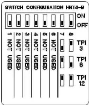
- DIL switch numbers 7 and 8 should be set as diagram opposite.
- For Gas boilers set the TPI setting to 6 cycles per hour. (Default setting)
- For Oil boilers set the TPI setting to 3 cycles per hour.
- For Electric heating set the TPI setting to 12 cycles per hour.
text_image
SWITCH CONFIGURATION HRT4-B ON OFF 1 NOT USED 2 NOT USED 3 NOT USED 4 NOT USED 5 NOT USED 6 NOT USED 7 8 TPI 3 TPI 6 TPI 12Switch positions for different TPI settings.
Thermostat specifications HRT4-B
Power Supply 2 x AAA alkaline batteries
Contact rating 3 (1)amp at 230v AC
Temperature accuracy +/- 0.5°C
Contact type Micro disconnection Volt free changeover
Dimensions 86mm x 86mm x 36.25mm
Pollution control Degree2
Design standard EN60730-2-9
Temperature range HRT4-B 5-30°C
Rated Impulse voltage Cat 1 - 1500v
Enclosure protection IP30
HORSTMANN
Horstmann Controls
South Bristol Business Park, Roman Farm Road, Bristol BS4 1UP
E-mail: sales@horstmann.co.uk
Web site: www.horstmann.co.uk