
Arvada - Fan HUNTER - Free user manual and instructions
Find the device manual for free Arvada HUNTER in PDF.


User questions about Arvada HUNTER
0 question about this device. Answer the ones you know or ask your own.
Ask a new question about this device
Download the instructions for your Fan in PDF format for free! Find your manual Arvada - HUNTER and take your electronic device back in hand. On this page are published all the documents necessary for the use of your device. Arvada by HUNTER.
USER MANUAL Arvada HUNTER
Congratulations on purchasing your new Hunter® ceiling fan! It will provide comfort and performance in your home or office for many years. This installation and operation manual contains complete instructions for installing and operating your fan.
We are proud of our work and appreciate the opportunity to supply you with the best ceiling fan available anywhere in the world.
To register your fan, please visit: www.HunterFan.com/register
Save your receipt for proof of purchase.
What to Expect with Your Installation
Tools Needed
Mounting Options
Ceiling Bracket
Light KitBlades

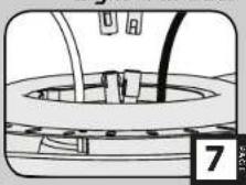
Downrod
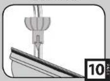
Wiring
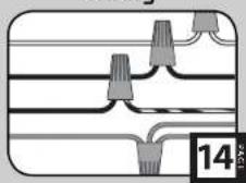
Canopy
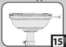
Globe
Remote Control
Operation,
Maintenance & Cleaning
Troubleshooting

M3523-01 · 05/14/14 · Ⓞ Hunter Fan Company
What to Expect with Your Installation
www.HunterFan.com
1.888.830.13261.888.830
natural_image
Pure technical diagram of a mechanical component with no visible text, numbers, or symbols
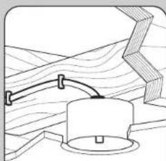
Must be able to
secure the fan to
building structure or
Tan-rated outlet box
If you are unfamiliar with wiring, use a qualified electrician.
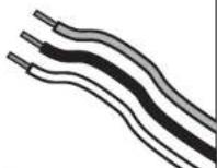

Know your wiring
text_image
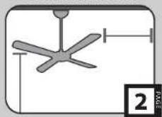
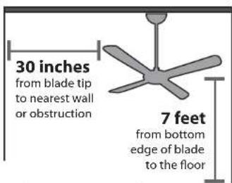
30 inches from blade tip to nearest wall or obstruction 7 feet from bottom edge of blade to the floor
Assess location
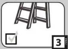
You may need a friend to help you.


Check box to see
fan weight

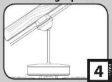
Ceiling angles greater than 34^ will require an Angled Mounting Kit. See page 4 for details.

Assess ceiling angle

Standard Downrod
for ceilings 8-10 feet high

Longer Downrod
for ceilings 10 feet or higher

Select a downrod length
Read and Save These Instructions
This product conforms to UL Standard 507.
WARNINGS
w.1 - To reduce the risk of fire, electrical shock, or personal injury, mount fan directly from building structure and/or an outlet box marked acceptable for fan support of 70 lbs (31.8 kg) and use the mounting screws provided with the outlet box,
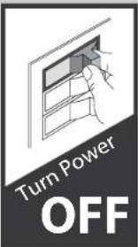
w.2 - To avoid possible electrical shock, before installing or servicing your fan, disconnect the power by turning off the circuit breakers to the outlet box and associated wall switch location. If you cannot lock the circuit breakers in the off position, securely fasten a prominent warning device, such as a tag, to the service panel,
w.3 - To reduce the risk of fire, electrical shock, or motor damage, use only Hunter Speed Controls.
w.4 - To reduce the risk of personal injury, do not bend the blade brackets when installing the blade brackets, balancing the blades, or cleaning the fan. Do not insert foreign objects in between rotating fan blades.
CAUTIONS
c.1 - All wiring must be in accordance with national and local electrical codes ANSI/NFPA 70. If you are unfamiliar with wiring, use a qualified electrician.
c.2 - Use only Hunter replacement parts.
This equipment has been tested and found to comply with the limits for a Class B digital device, pursuant to part 15 of the FCC Rules. These limits are to provide reasonable protection against harmful interference in a residential installation. This equipment generates, uses and can radiate radio frequency energy and if not installed and used in accordance with the instructions may cause harmful interference to radio communications.

M3523-01 · 05/14/14 · © Hunter Fan Company
Tools Needed
www.HunterFan.com
1.888.830.1326
natural_image
Simple line drawing of a ladder with a checkmark label (no text or symbols on the ladder itself)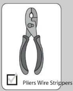
natural_image
Illustration of pliers wire strippers (no text or symbols on the diagram itself)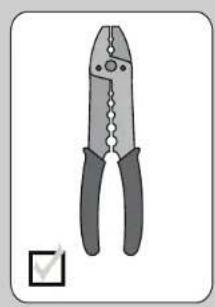
natural_image
Illustration of a pair of pliers with black handles and a white checkmark (no text or symbols on the pliers themselves)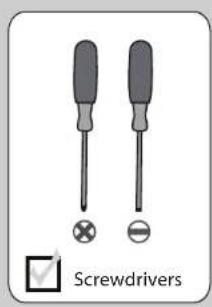
text_image
Screwdrivers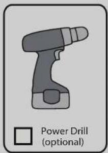
text_image
Power Drill (optional)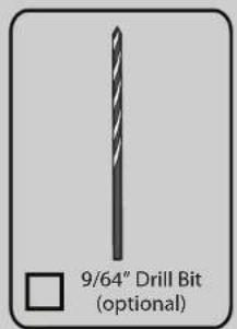
text_image
9/64" Drill Bit (optional)If you are installing multiple remote-controlled fans on the same circuit breaker,
you may need to perform a few extra steps to prevent interference or faulty operation of your remote controls.
Go to www.HunterFan.com/FAQs and click "How do I properly install multiple remote-controlled fans?" for more information.
If mounting to a support structure, you will also need these tools.

M3523-01 · 05/14/14 · Ⓞ Hunter Fan Company
CEILING
If you have a flat ceiling:
Hang your fan by a standard downrod (included).
OPTION 1
If you have an angled ceiling:
- You will need a longer downrod (sold separately).
- If your ceiling angle is greater than 34^ , you will also need an Angled Mounting Kit (sold separately).
OPTION 2
Use the three steps below to determine if your ceiling angle is greater than 34^
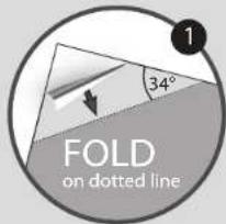
text_image
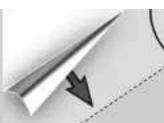
FOLD on dotted line
text_image
PLACE against wall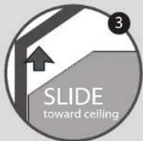
text_image
3 SLIDE toward ceiling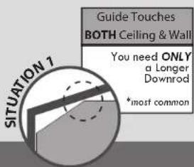
text_image
SITUATION 7 Guide Touches BOTH CEILING & WALL You need ONLY a Longer Downrod *most common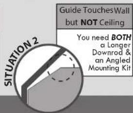
text_image
SITUATION 2 Guide Touches Wall but NOT Ceiling You need BOTH a Longer Downrod & an Angled Mounting KitMounting Options
www.HunterFan.com
1.888.830.1326
text_image
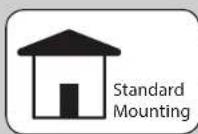
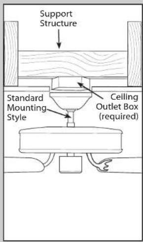
Support Structure Standard Mounting Style Ceiling Outlet Box (required)Use Standard Mounting to hang the fan from a flat ceiling.
text_image
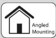
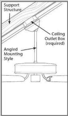
Support Structure Ceiling Outlet Box (required) Angled Mounting StyleUse Angled Mounting
to hang the fan from a
vaulted or angled ceiling.

M3523-01 · 05/14/14 · Ⓞ Hunter Fan Company
Ceiling Bracket
www.HunterFan.com
1.888.830.1326
text_image
Turn Power OFF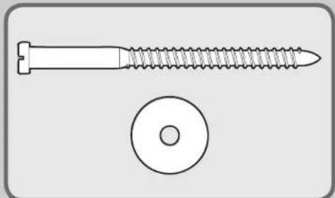
natural_image
Technical illustration of a screw and a washer (no text or symbols)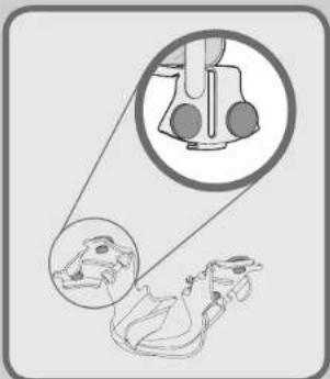
natural_image
Diagram showing a device with two circular insets highlighting internal components (no text or symbols)Make sure all four bumpers are still attached.

text_image
For angled ceilings, point opening toward peak.If you are unable to do this, call Technical Support at 1-888-830-1326.
natural_image
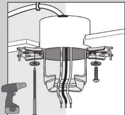
Technical diagram of a mechanical assembly with screw fasteners and a tool (no text or labels)Use wood screws
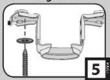
(included) when securing to support structure with approved electrical outlet box. Drill 9/64" pilot holes in support structure to aid in securing ceiling bracket with hardware found in the ★ hardware bag.
Use machine screws
(provided with outlet box) when securing to existing ceiling fan-rated outlet box. Make sure it is securely installed and is acceptable for fan support of 31.8 kg (70 lbs) or less.
natural_image
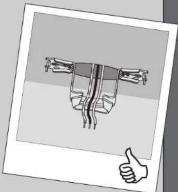
Diagram of a mechanical component with a thumbs-up gesture, no visible text or symbolsTo avoid possible electrical shock, before installing your fan, disconnect the power by turning off the circuit breakers to the outlet box associated with the wall switch location.
Refer to warning w.1 on pg. 2


M3523-01 · 05/14/14 · © Hunter Fan Company
Blades
www.HunterFan.com
1.888.830.1326

natural_image
Mechanical assembly diagram showing a tool interacting with a circular component (no text or symbols visible)Turn the fan motor upside-down and place it in one of the holes in the packaging.
natural_image
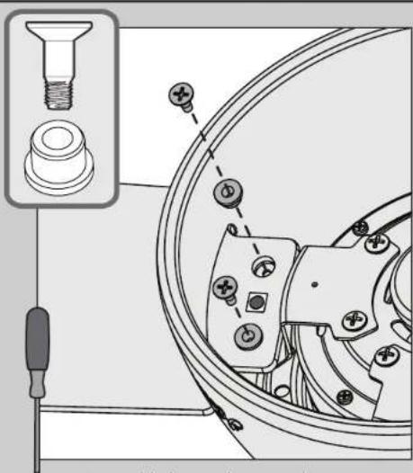
Technical diagram of a mechanical assembly with screw fasteners and a component, no visible text or symbols
Insert a blade into the motor housing.
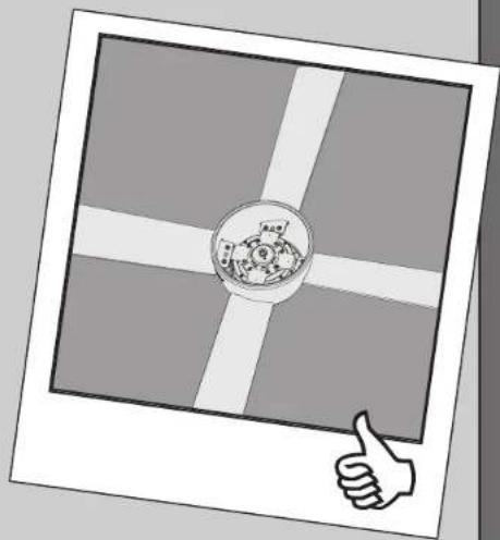
Attach each blade to the fan using two blade grommets, found in the ■ hardware bag, and two blade assembly screws, found in the ▲ hardware bag.
Note: Each blade will only install one way and will have a red dot on the bottom of the blade. It should face you during blade installation or downward once fan is hung.
natural_image
Illustration of a globe with a circular emblem and a thumbs-up gesture, framed by a white border (no text or symbols)
Your blades are shielded with Dust Armor® which is a nanotechnology coating that repels dust. For cleaning the fan, use soft brushes or cloths to prevent scratching. Cleaning agents may damage the finishes.

M3523-01 · 05/14/14 · Ⓞ Hunter Fan Company
Light Kit
www.HunterFan.com
1.888.830.1326
text_image
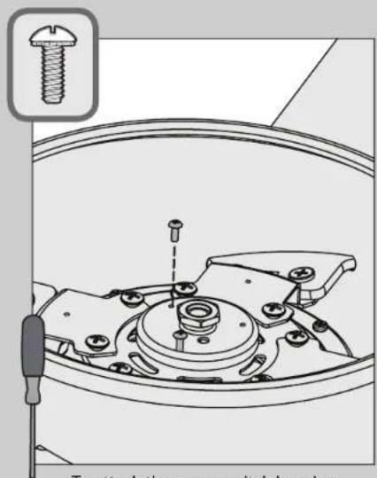
To attach the upper switch housing.
To attach the upper switch housing, partially install two switch housing assembly screws, found in the ≡ hardware tag, into the switch housing mounting plate.
natural_image
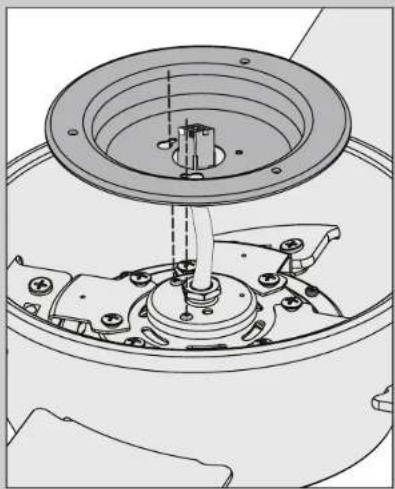
Technical line drawing of a mechanical assembly with a central hub and mounting base (no text or symbols)Feed the wire plug through the center hole of the upper switch housing, then wrap keyhole slots around the screws and twist counterclockwise.
natural_image
Technical line drawing of a mechanical component with concentric rings and a screw inserted (no text or symbols)
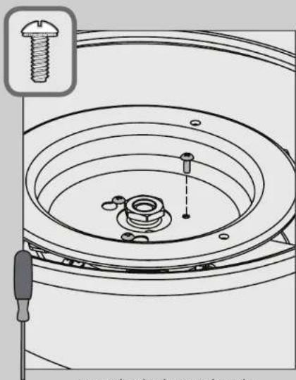
Insert the third screw, found in the ≡ hardware bag, into place and then tighten all three (3) screws.
Make sure the upper switch housing is securely attached to the mounting plate. Failure to properly secure all 3 assembly screws could result in the switch housing fixture falling.

M3523-01 · 05/14/14 · © Hunter Fan Company
Light Kit (continued)
www.HunterFan.com
1.888.830.1326
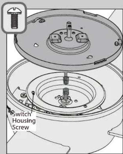
text_image
Switch Housing ScrewPartially install two of the switch housing screws found in the ≡ bag. Connect the plugs from the upper and lower switch housings. Make sure to line up the colored markings on the connectors.
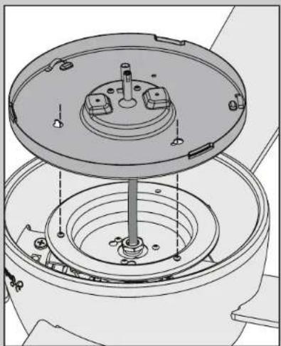
natural_image
Technical line drawing of a mechanical assembly with concentric circular components and mounting holes (no text or symbols)Align the keyhole slots in the lower switch housing with the switch housing screws. Place the lower switch housing, then twist the lower switch housing counterclockwise to lock into place.
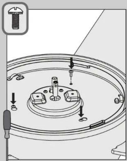
text_image
Technical diagram showing mechanical assembly with labeled parts and directional arrows indicating assembly steps[NO TEXT]
Install the third switch housing screw. Tighten all three screws securely.

M3523-01 · 05/14/14 · © Hunter Fan Company
Make sure the lower switch housing is securely attached to the upper switch housing. Failure to properly secure all three assembly screws could result in the light fixture falling.

Light Kit (continued)
www.HunterFan.com
1.888.830.1326
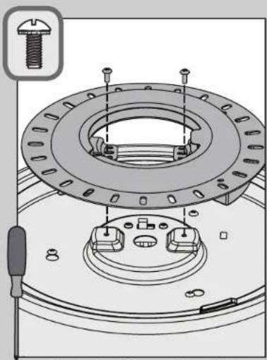
natural_image
Technical diagram of a mechanical assembly with bolts and a central circular component (no text or symbols)×
Attach the LED assembly to the lower switch housing by installing two light kit assembly screws, found in the ≡ hardware bag. Insert the screws through the slots, not the screw holes, in the LED assembly.
natural_image
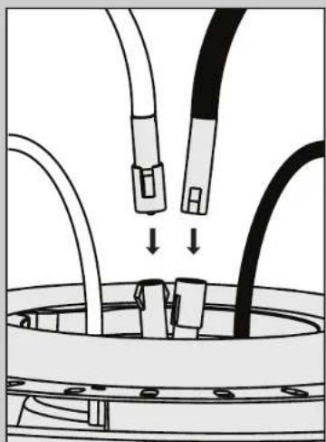
Diagram of cable connections with connectors and a central connector (no text or symbols)Connect the plug connectors between the black wire and the black wire with a white stripe. Connect the plug connectors between the two white wires.
natural_image
Simple line drawing of a mechanical device with a thumbs-up gesture (no text or symbols)
M3523-01 · 05/14/14 · © Hunter Fan Company
Option 1
text_image
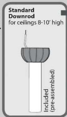
Standard Downrod for ceilings 8-10' high Included (pre-assembled)Option 2
text_image
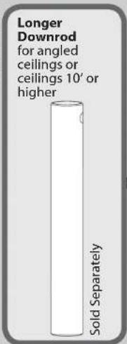
Longer Downrod for angled ceilings or ceilings 10' or higher Sold SeparatelyIf you need a different downrod length follow these steps:
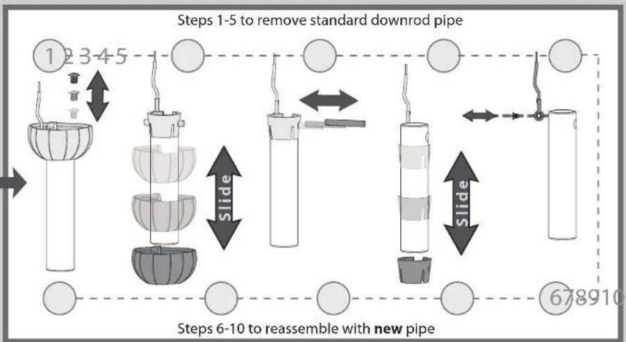
flowchart
graph TD
    A["Step 1-5 to remove standard downrod pipe"] --> B["Step 6-10 to reassemble with new pipe"]
    B --> C["Step 1-5 to remove standard downrod pipe"]
    C --> D["Step 6-10 to reassemble with new pipe"]
    D --> E["Step 1-5 to remove standard downrod pipe"]
    E --> F["Step 6-10 to reassemble with new pipe"]
    F --> G["Step 1-5 to remove standard downrod pipe"]
    G --> H["Step 6-10 to reassemble with new pipe"]
    H --> I["Step 1-5 to remove standard downrod pipe"]
    I --> J["Step 6-10 to reassemble with new pipe"]

M3523-01 · 05/14/14 · © Hunter Fan Company
Downrod (continued)
www.HunterFan.com
1.888.830.1326
text_image
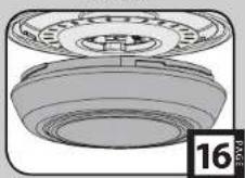
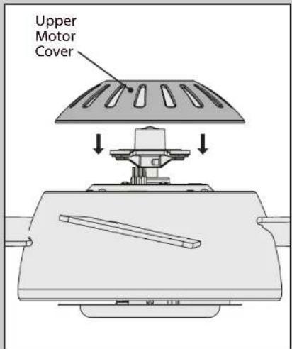
Upper Motor CoverPlace the upper motor cover on the top of the fan.
text_image
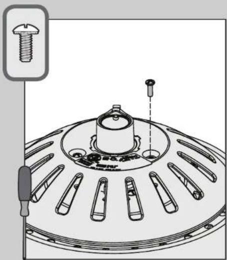
Technical diagram of a mechanical component with screw fasteners and a labeled inset showing a bolt detail.Align the notches in the upper motor cover with the tabs on the motor adapter. Insert the upper motor screws, found in the ● hardware bag, and tighten them securely.
text_image
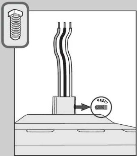
KEEPRemove the pre-installed setscrew so that the downrod can be inserted.

M3523-01 · 05/14/14 · © Hunter Fan Company
natural_image
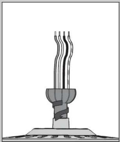
Illustration of a three-wireed electrical fuse or lamp with three leads, mounted on a base (no text or symbols visible)Hand tighten the downrod (at least 4-5 full turns) until it stops.

text_image
3/8" 8" (not to scale) CUT & STRIPThe wires can be cut, but leave at least 8" extending from the top of the downrod.
natural_image
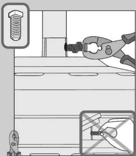
Illustration of a hand using pliers to adjust a screw on a shelf, with no visible text or symbols.Tighten the setscrew with pliers. DO NOT HAND TIGHTEN.
8"
3/8"

M3523-01 · 05/14/14 · © Hunter Fan Company
If the setscrew is not tightened securely, the fan may fall.

Downrod (continued)
www.HunterFan.com
1.888.830.1326

natural_image
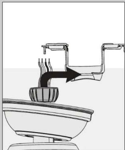
Diagram of a steaming bowl with three handles, emitting steam from a downward arrow (no text or symbols)Put the wires and downrod through the canopy. Let the canopy sit loosely on top of the fan.
natural_image
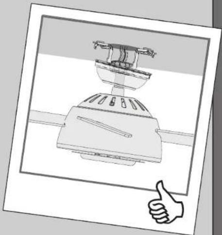
Line drawing of a toilet with steam rising from a bowl (no text or symbols)DO NOT PICK THE FAN UP BY THE CANOPY OR WIRES. Place the downrod ball into the slot in the ceiling bracket.
natural_image
Illustration of a toaster oven with a hand giving a thumbs-up gesture (no text or symbols)
M3523-01 · 05/14/14 · Ⓞ Hunter Fan Company
Wiring
www.HunterFan.com
1.888.830.1326
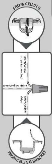
Using an orange wire connector from the ★ hardware bag, connect the 3 grounding wires (green, green/yellow stripe, or bare copper) coming from the ceiling, downrod, and hanging bracket.
flowchart
graph TD
    A["FROM CEILING"] --> B["GREEN/Yellow stripe"]
    B --> C["GREEN/Yellow stripe"]
    C --> D["GREEN/Yellow stripe"]
    D --> E["GREEN/Yellow stripe"]
    E --> F["GREEN/Yellow stripe"]
    F --> G["GREEN/Yellow stripe"]
    G --> H["GREEN/Yellow stripe"]
    H --> I["GREEN/Yellow stripe"]
    I --> J["GREEN/Yellow stripe"]
    J --> K["GREEN/Yellow stripe"]
    K --> L["GREEN/Yellow stripe"]
    L --> M["GREEN/Yellow stripe"]
    M --> N["GREEN/Yellow stripe"]
    N --> O["GREEN/Yellow stripe"]
    O --> P["GREEN/Yellow stripe"]
    P --> Q["GREEN/Yellow stripe"]
    Q --> R["GREEN/Yellow stripe"]
    R --> S["GREEN/Yellow stripe"]
    S --> T["GREEN/Yellow stripe"]
    T --> U["GREEN/Yellow stripe"]
    U --> V["GREEN/Yellow stripe"]
    V --> W["GREEN/Yellow stripe"]
    W --> X["GREEN/Yellow stripe"]
    X --> Y["GREEN/Yellow stripe"]
    Y --> Z["GREEN/Yellow stripe"]
    Z --> AA["GREEN/Yellow stripe"]
    AA --> AB["GREEN/Yellow stripe"]
    AB --> AC["GREEN/Yellow stripe"]
    AC --> AD["GREEN/Yellow stripe"]
    AD --> AE["GREEN/Yellow stripe"]
    AE --> AF["GREEN/Yellow stripe"]
    AF --> AG["GREEN/Yellow stripe"]
    AG --> AH["GREEN/Yellow stripe"]
    AH --> AI["GREEN/Yellow stripe"]
    AI --> AJ["GREEN/Yellow stripe"]
    AJ --> AK["GREEN/Yellow stripe"]
    AK --> AL["GREEN/Yellow stripe"]
    AL --> AM["GREEN/Yellow stripe"]
    AM --> AN["GREEN/Yellow stripe"]
    AN --> AO["GREEN/Yellow stripe"]
    AO --> AP["GREEN/Yellow stripe"]
    AP --> AQ["GREEN/Yellow stripe"]
    AQ --> AR["GREEN/Yellow stripe"]
    AR --> AS["GREEN/Yellow stripe"]
    AS --> AT["GREEN/Yellow stripe"]
    AT --> AU["GREEN/Yellow stripe"]
    AU --> AV["GREEN/Yellow stripe"]
    AV --> AW["GREEN/Yellow stripe"]
    AW --> AX["GREEN/Yellow stripe"]
    AX --> AY["GREEN/Yellow stripe"]
    AY --> AZ["GREEN/Yellow stripe"]
    AZ --> BA["GREEN/Yellow stripe"]
    BA --> BB["GREEN/Yellow stripe"]
    BB --> BC["GREEN/Yellow stripe"]
    BC --> BD["GREEN/Yellow stripe"]
    BD --> BE["GREEN/Yellow stripe"]
    BE --> BF["GREEN/Yellow stripe"]
    BF --> BG["GREEN/Yellow stripe"]
    BG --> BH["GREEN/Yellow stripe"]
    BH --> BI["GREEN/Yellow stripe"]
    BI --> BJ["GREEN/Yellow stripe"]
    BJ --> BK["GREEN/Yellow stripe"]
    BK --> BL["GREEN/Yellow stripe"]
    BL --> BM["GREEN/Yellow stripe"]
    BM --> BN["GREEN/Yellow stripe"]
    BN --> BO["GREEN/Yellow stripe"]
    BO --> BP["GREEN/Yellow stripe"]
    BP --> BQ["GREEN/Yellow stripe"]
    BQ --> BR["GREEN/Yellow stripe"]
    BR --> BS["GREEN/Yellow stripe"]
    BS --> BT["GREEN/Yellow stripe"]
    BT --> BU["GREEN/Yellow stripe"]
    BU --> BV["GREEN/Yellow stripe"]
    BV --> BW["GREEN/Yellow stripe"]
    BW --> BX["GREEN/Yellow stripe"]
    BX --> BY["GREEN/Yellow stripe"]
    BY --> BZ["GREEN/Yellow stripe"]
    BZ --> CA["GREEN/Yellow stripe"]
    CA --> CB["GREEN/Yellow stripe"]
    CB --> CC["GREEN/Yellow stripe"]
    CC --> CD["GREEN/Yellow stripe"]
    CD --> CE["GREEN/Yellow stripe"]
    CE --> CF["GREEN/Yellow stripe"]
    CF --> CG["GREEN/Yellow stripe"]
    CG --> CH["GREEN/Yellow stripe"]
    CH --> CI["GREEN/Yellow stripe"]
    CI --> CJ["GREEN/Yellow stripe"]
    CJ --> CK["GREEN/Yellow stripe"]
    CK --> CR["GREEN/Yellow stripe"]
    CR --> CS["GREEN/Yellow stripe"]
    CS --> CT["GREEN/Yellow stripe"]
    CT --> CU["GREEN/Yellow stripe"]
    CU --> CV["GREEN/Yellow stripe"]
    CV --> CW["GREEN/Yellow stripe"]
    CW --> CX["GREEN/Yellow stripe"]
    CX --> CY["GREEN/Yellow stripe"]
    CY --> CZ["GREEN/Yellow stripe"]
Note: To connect the wires, hold the bare metal leads together and place a wire connector over them, then twist clockwise until tight.
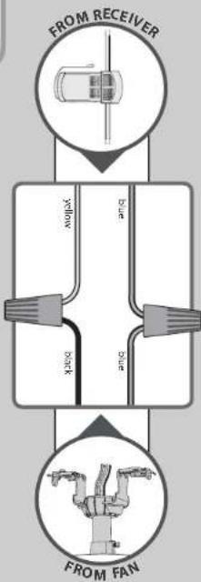
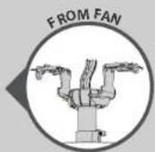
Using the orange wire connectors from the remote control hardware bag, connect the blue wire from the receiver to the blue wire (or possibly black with white stripe wire) from the fan. Connect the yellow wire from the receiver to the black wire from the fan.
flowchart
graph TD
    A["FROM FAN"] --> B["Black"]
    B --> C["Blue"]
    C --> D["Yellow"]
    D --> E["From Receiver"]
    style A fill:#f9f,stroke:#333
    style B fill:#ccf,stroke:#333
    style C fill:#cfc,stroke:#333
    style D fill:#fcc,stroke:#333
    style E fill:#ffc,stroke:#333
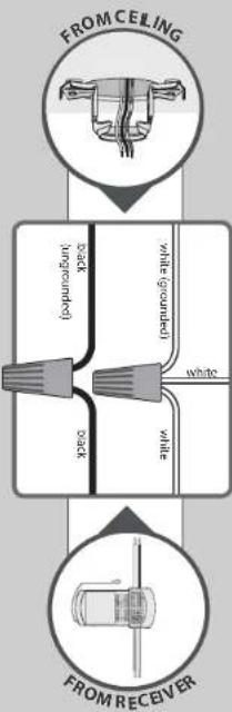
Using the orange wire connectors from the ★ hardware bag, connect the black wire (ungrounded) from the ceiling to the black wire from the receiver. Connect the white wire (grounded) from the ceiling to both the white wire from the receiver and the white wire from the fan.
flowchart
graph TD
    A["FROM CEILING"] --> B["BACK (grounded)"]
    B --> C["White (grounded)"]
    C --> D["white"]
    D --> E["FROM RECEIVER"]
    E --> F["Back"]
Refer to CAUTION c.1 on pg. 2

Turn the splices upward and push them carefully back through the hanger bracket into the outlet box. Spread the wires apart, with the grounded wires on one side of the outlet box and the ungrounded wires on the other side of the outlet box.

M3523-01 · 05/14/14 · © Hunter Fan Company
Canopy
www.HunterFan.com
1.888.830.1326
natural_image
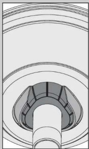
Technical line drawing of a mechanical component with concentric circular layers and a central cylindrical shaft (no text or symbols)Position the canopy so that, when lifted into place, the canopy fits into the hanging bracket as shown.
text_image
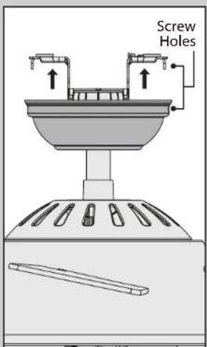
Screw HolesLift the canopy into place so that the screw holes are aligned.
natural_image
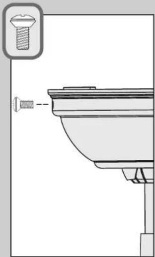
Technical line drawing of a mechanical component with a screw inserted, no text or symbols presentInsert the two canopy screws found in the ● hardware bag.
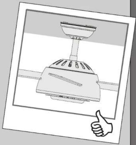
natural_image
Illustration of a kitchen appliance with a hand giving a thumbs-up gesture (no text or symbols)Note: Fan style may vary.

M3523-01 · 05/14/14 · @ Hunter Fan Company
Globe
www.HunterFan.com
1.888.830.1326
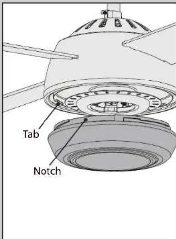
text_image
Tab NotchPosition the notches in the outer rim of the globe so they line up with the tabs on the inside surface of the light fixture rim.
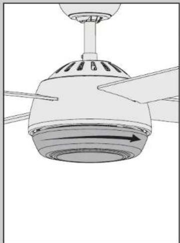
natural_image
Diagram of a ceiling fan with blades and central hub, showing airflow direction (no text or symbols)Carefully lift the globe up inside the light fixture as far as it will go. Rotate the globe in a clockwise direction until it is held tightly in place by the three tabs.
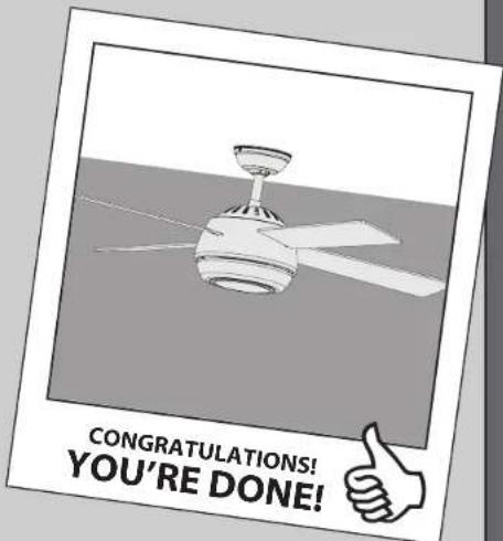
text_image
CONGRATULATIONS! YOU'RE DONE!See next page for fan operation instructions.


M3523-01 · 05/14/14 · Ⓞ Hunter Fan Company
Remote Control
www.HunterFan.com
1.888.830.1326
text_image
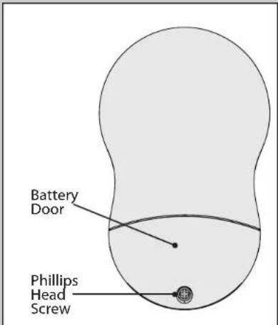
Battery Door Phillips Head ScrewTo access the battery compartment, remove the small Phillips head screw that secures the battery door to the transmitter assembly. The battery should be installed with the positive (+) side up. Replace with a CR2032 battery when necessary.
If you are installing multiple remote-controlled fans on the same circuit breaker, you may need to perform a few extra steps to prevent interference or faulty operation of your remote controls.
Go to www.HunterFan.com/FAQs and click "How do I properly install multiple remote-controlled fans?" for more information.
text_image
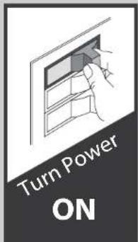
Turn Power ON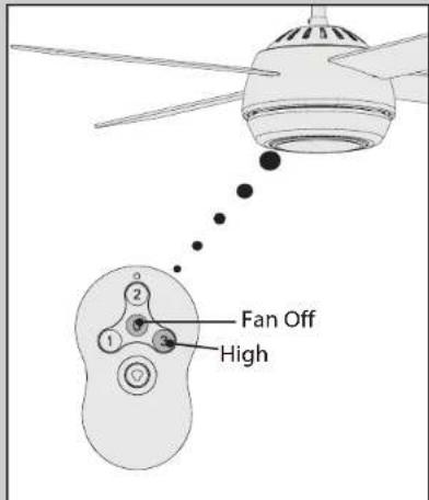
text_image
Fan Off HighNote: The remote must be paired before the fan will operate.
Within 3 minutes of restoring power to the fan, press both the Fan Off button and the High button for at least 4 seconds. Your fan will turn on low to indicate successful syncing. If it does not, turn off power to your fan, wait 1 minute then try again. If using the transmitter with multiple fans, repeat this process for each fan.

M3523-01 · 05/14/14 · © Hunter Fan Company
Operation, Maintenance, & Cleaning
www.HunterFan.com
1.888.830.1326
text_image
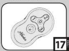
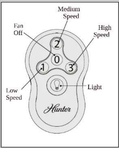
Fan Off 2 Medium Speed High Speed 1 0 3 Light Low Speed HunterTo turn on fan, press a fan speed button. Speeds range from off (0) to high (3). Quickly press the Light button to turn the lights off and on. Hold the Light button to raise and dim the light level.
text_image
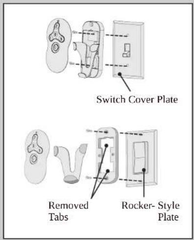
Switch Cover Plate Removed Tabs Rocker- Style PlateTo install the transmitter cradle, remove the two screws holding the switch cover plate. Do not remove the cover plate. Orient the cradle
by lining up the two mounting holes with those on the cover plate. Insert and tighten the screws. Do not over tighten.
Note: For rocker-style cover plates, break off the tabs by pushing outward.
text_image
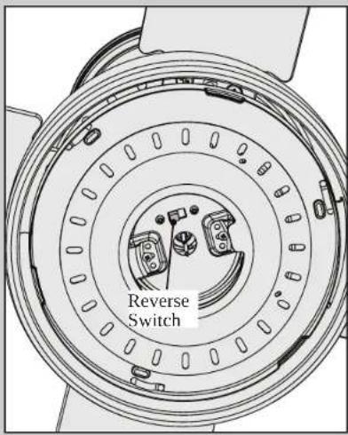
Reverse SwitchTo switch the direction of air flow, remove the glass on the fan by pushing up on the glass and rotating the shade in a counterclockwise direction until the glass unlocks from the fan. Flip the black switch to change the direction.

M3523-01 · 05/14/14 · © Hunter Fan Company
Operation, Maintenance, & Cleaning (continued)
www.HunterFan.com
1.888.830.1326
text_image
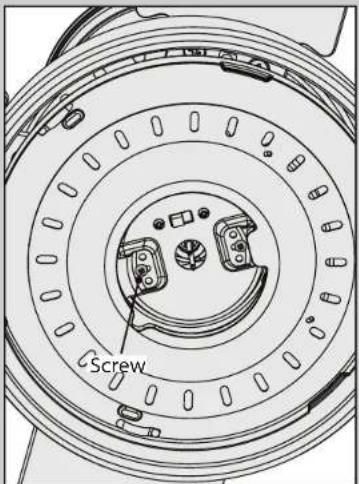
ScrewTo change the bulbs, use a Phillips Head screwdriver to remove the screws that secure the LED light ring to the lower switch housing. Replace with a Hunter approved replacement LED light ring. Reinstall the globe assembly.
natural_image
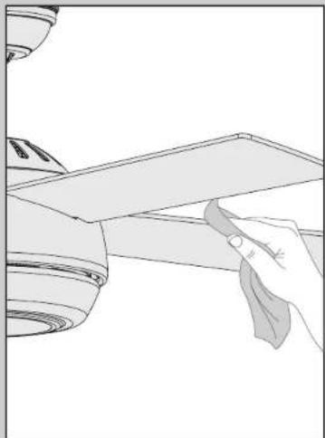
Line drawing of a hand holding a tool over a flat surface, no text or symbols presentWhen cleaning the fan, use soft brushes or cloths to prevent scratching. Cleaning products may damage the finishes.
Safe-Exit
The Safe-Exit Program gives you about thirty seconds of light when you turn the lights off to exit the room before the lights go out. To use Safe-Exit:
- Press the Fan Off button for at least three seconds to initiate the Safe-Exit Mode.
• The lights will flash for visual confirmation. - The lights will stay on 50% brightness for 15 seconds and then begin to dim. After a total of 30 seconds, the lights will be completely off.

M3523-01 · 05/14/14 · @ Hunter Fan Company
Troubleshooting
www.HunterFan.com
1.888.830.1326
Fan doesn't work
• Make sure power switch is on.
- Push the motor reversing switch firmly left or right to ensure that it is engaged.
- Check the circuit breaker to ensure the power is turned on.
• Make sure the blades spin freely.
- Turn off power from the circuit breaker, then loosen the canopy and check all the connections according to the wiring diagram on page 14.
- Check the plug connection in the switch housing.
Remote control of fan is erratic
• Make sure the battery is installed correctly.
• Install a fresh battery.
Transmitter only works when held at close range
• Install a fresh battery.
Excessive wobbling
• Tighten all of the blade and blade iron screws until they are snug.
- Use the provided balancing kit and instructions to balance the fan.
Noisy Operation
- Tighten the blade and blade iron screws until they are snug.
- Check to see if any of the blades are cracked. If so, replace all of the blades.
If you have multiple remotes or multiple remote-controlled fans installed on the same circuit
breaker and you are experiencing interference or faulty operation of your remote controls, please go to www.HunterFan.com/FAQs and click "How do I properly install multiple remote-controlled fans?" for information on how to correct this issue.

Hunter fans have the power to cut your cooling costs up to 40%.
Beat the High Cost of Cooling
The air movement created by a Hunter ceiling fan lets you set your thermostat higher and still stay comfortable. Every degree you raise the thermostat saves up to 7% on energy costs. So, you can cut back on expensive air conditioning ... and save up to 40%* on cooling. In winter, your Hunter fan recirculates warm air and saves up to 10%* on heating bills. * On average at low speed settings. Your savings may vary based on climate, building type and thermostat setting.
Save Energy and Money While Protecting the Environment
Congratulations! You're saving energy and money while protecting the environment by purchasing this ENERGY STAR qualified Hunter ceiling fan! With this purchase, you are doing your part to protect the environment. Your new ceiling fan has earned the ENERGY STAR label because it meets high energy efficiency specifications set by the Environmental Protection Agency (EPA). ENERGY STAR labeled ceiling fans save energy because they have more efficient fan motors and air delivery due to more aerodynamic blade configurations. Ceiling fan models bearing the ENERGY STAR label move air 14 - 20% more efficiently than typical ceiling fan models. For more information on ENERGY STAR visit www.energystar.gov.