DF-515151 - Rear Camera Veise - Free user manual and instructions
Find the device manual for free DF-515151 Veise in PDF.


User questions about DF-515151 Veise
0 question about this device. Answer the ones you know or ask your own.
Ask a new question about this device
Download the instructions for your Rear Camera in PDF format for free! Find your manual DF-515151 - Veise and take your electronic device back in hand. On this page are published all the documents necessary for the use of your device. DF-515151 by Veise.
USER MANUAL DF-515151 Veise
Car Rear View Security System User Guide
natural_image
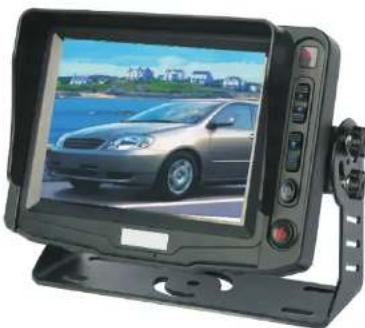
Front view of a black rectangular electronic device displaying a car on a road, with no visible text or symbols.! Warning
- Specifications and manual content are subject to change without any notice.
● Before using the products, please read the manual and preserve it well.
KIT CHARACTERISTICS
★Five inch high resolution color TFT LCD.
★Free power input: DC11V-32V.
★Three-channel CVBS input, one-channel video input.
★Normal/mirror image setup.
★Automatic/manual selection, when automatic, monitor in sleeping mode.
★Compulsory signal switch: The images from CAM1 or CAM2 will be activated automatically, when backing up the car or opening the door of car. Reversing image priority.
★Power supply of camera: while CAM1/CAM2 is in operation, power of CAM2/CAM1 will be cut off automatically. Effectively prolong the life of the cameras and fulfill the objective of saving car power.
★Jacks of AV input and output.
★Automatic induction of LED indicator. It will be activated automatically while the environment is dark, so that the user still can see the key of the monitor clearly.
★Double PCB, effectively heighten the ability of shock resistance.(8G)
★Remote control or manual operation.
★Shell of the monitor is made from ABS resisting high temperature and blast.
★Blue light indicates startup, and red light indicates sleeping mode.
Before you request for repair
Phenomena below are not necessary mean failure with Display.
Please check off per following methods before you request for repair.
| Phenomena | Possible Causes |
| No picture, no sound | Improper connection with Automobile adapter. Use of unauthorized power supply.Power Switch is on OFF position. |
| No picture | Check whether AV line is plugged well. |
| No sound | Whether audio wire is connected well, or the sound volume is turned off or till minimum. |
| Dark picture | Whether bright and contrast adjust correctly;Whether environment temperature too low. |
| No color | Whether color is well-adjusted |
| Upside down or lateral inverted picture | Maybe improperly adjusted Horizontal,Vertical on the remote controller. |
| No backing function (i.e. Picture) | Whether the single blown/blue AV wire connecting to the positive power cord of reversing light is loose or not. Whether the connection head of red CAM socket is of poor contact. |
SYSTEM CONNECTION
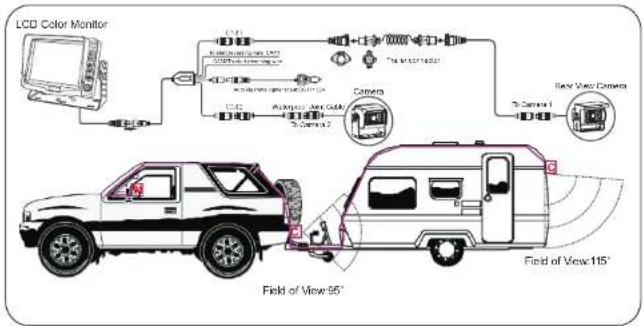
V、Trailer backup camera system connection
text_image
LCD Color Monitor Field of View 95° Field of View 115°


Accessories
 U-shape Mount U-shape Mount |  Remote control Remote control | 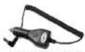 Cigarette lighter adaptor Cigarette lighter adaptor |
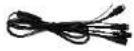 switching cable switching cable | 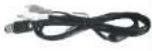 4pin screw AV Cable 4pin screw AV Cable |  extension cable extension cable |
 |  |  Trailer extensionTrailer Trailer extensionTrailer |
PRECAUTIONS
★Before using our products, please read this manual first.
★Before connection to power, please check the connection of cables, if improper connection occurs, it may damage the picture.
★The monitor is not waterproof, please don not place the monitor outdoor.
★In order to avoid damaging the components, please do not use the products, while welding in your car.
★Please make sure all the cables are connected lightly, or else the system will not work well.
★Do not open the housing of the camera, otherwise the waterproof device and chipset inside it will be demaged.
★Please do not put the cables together with high temperature and rotary objects.
★In order to evacuate the hight temperature inside the monitor, please do not jam the holes in the shell.
★High voltage inside the monitor, non-specialist do not open the back shell.
★While driving, please do not watch DVD, etc.
★Please do not use caustic chemicals to wipe the camera and monitor.
! Warning
There is not any repairable parts in the system, so please do not take apart the CCD camera or the monitor. It is dangerous with the high voltage in the products. It must be the special worker to repair and regulate the products.
! Notice
This manual is just for reference. Any changes with the information, we will not give notice to yu. Any wrongor un-detailed thing, the explanation right belongs to the manufacturer.
MONITOR
I、Technical parameters
| Display Device | Color TFT-LCD | |
| Size | 5.0 inch (Diagonal) | |
| Interface | Digital TTL | Analog |
| Resolution | 640×RGB×480 | 320×RGB×234 |
| Dot Pitch(mm) | 0.0529(W)X0.1587(H) | 0.107(W)X0.319(H) |
| Luminance (nits) | 300 | 300 |
| Contrast Ratio | 500:1 | 500:1 |
| Response Time (ms) | 25 | 25 |
| View Angle (LR/UD) | 130/140 | 110/50 |
| Audio output | ≤1W | |
| Loudspeaker | 4.0cm,16Q/1W | |
| Connect plug | 9/13pinsS-VIDEO | |
| Application Power Supply | 1. AC power supply-AC Adapter(DC11V-32V)2. Automobile storage battery (12V/24V) Automobile adapter | |
| Power Consumption | 5W Max | |
| Outer Dimension | W152mm×H109mm×T50mm | |
| Weight | 350g | |

Special Notice
Bright spots or dark spots may appear on the screen. This is a normal phenomenon associated with the active matrix display technology and is not a sign of malfunction. Do not attempt to maintain. For any failures, please turn off the unit immediately and contact us or local dealer. This device integrates a great deal of fine electronic components. Disassembly or alternation may result in damages or breaks.
SYSTEM CONNECTION
III、System connection diagram 3
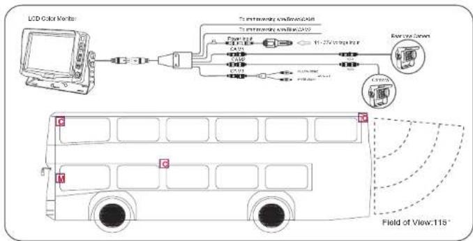
flowchart
graph LR
    A["LCD Color Monitor"] --> B["Sensor"]
    B --> C["Sensor"]
    C --> D["Display"]
    D --> E["Output"]
    F["Field of View: 115°"] --> G["Bus"]
    style F stroke:#000,stroke-width:2px
    style G stroke:#000,stroke-width:2px
VI、System connection diagram 4
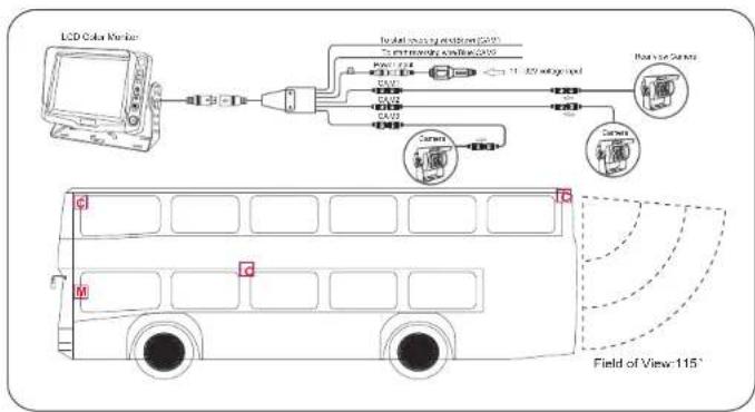
flowchart
graph TD
    A["LCD Color Monitor"] --> B["Signal"]
    B --> C["Camera"]
    C --> D["Display"]
    D --> E["Field of View: 115°"]
    style A fill:#f9f,stroke:#333
    style E fill:#bbf,stroke:#333
    style C fill:#dfd,stroke:#333
    style D fill:#dfd,stroke:#333
    style_F["Radio source Camera"] --> G["Sensor"]
    G --> H["Camera"]
    H --> I["Display"]
    I --> J["Field of View: 115°"]
SYSTEM CONNECTION
I, System connection diagram 1
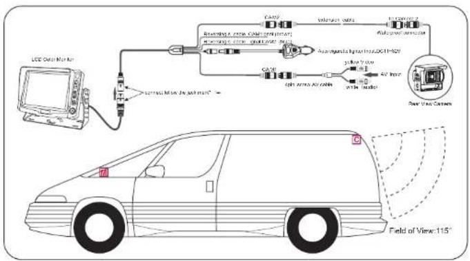
text_image
LCD Display Monitor Carry Switchset 100% Autovisual sensor Automotive light source:DCI-152V Carry Switchset 100% Autovisual sensor Automotive light source:DCI-152V Carry Switchset 100% Autovisual sensor Automotive light source:DCI-152V Carry Switchset 100% Autovisual sensor Automotive light source:DCI-152V Carry Switchset 100% Autovisual sensor Automotive light sources:DCI-152V Carry Switchset 100% Autovisual sensor Automotive light sources:DCI-152V Carry Switchset 100% Autovisual sensor Automotive light sources:DCI-152V Carry Switchset 100% Autovisual sensor Automotive light sources:DCI-152V Carry Switchset 100%- Autovisual sensor Automotive light sources:DCI-152V Carry Switchset 100% Autovisual sensor Automotive light sources:DCI-152V Carry Switchset 100% Autovisual sensor Automotive light sources:DCI-152V Carry Switchset 100% Autovisual sensor Automotive light sources:DCI-152V Carrying Switchset 100% Autovisual sensor Automotive light sources:DCI-152V Carrying Switchset 100% Autovisual sensor Automotive light sources:DCI-152V Carrying Switchset 100% Autovisual sensor Automotive light sources:DCI-152V Carrying Switchset 100% Autovisual sensor Automotive light sources:DCi-152V Carrying Switchset 100% Autovisual sensor Automotive light sources:DCi-152V Carrying Switchset 100% Autovisual sensor Automotive light sources:DCi-152V Carrying Switchset 100% Autovisual sensor Automotive light sources:DCi-152V Carrying Switchset 100% Autovisual Sensor Automotive Light Source:DCi-152V Carrying Switchset 100% Autovisual Sensor Automotive Light Source:DCi-152V Carrying Switchset 100% Autovisual Sensor Automotive Light Source:DCi-152V Carrying Switchset 100% Autovisual Sensor Automotive Light Source:DCi-152V Carrying Switchset 100%- Autovisual Sensor Automotive Light Source:DCi-152V Carrying Switchset 100% Autovisual Sensor Automotive Light Source:DCi-152V Carrying Switchset 100% Autovisual Sensor Automotive Light Source:DCi-152V Carrying Switchset 100% Autovisual Sensor Automotive Light Source:DCi-152V Carry Switchset 100% Autovisual Sensor Automotive Light Source:DCi-152V Carrying Switchset 100% Autovisual Sensor Automotive Light Source:DCi-152V Carrying Switchset 100% Autovisual Sensor Automotive Light Source:DCi-152V Carrying Switchset 100% Autovisual Sensor Automotive Light Source:DC-i-152V Field of View: 115°II. System connection diagram 2
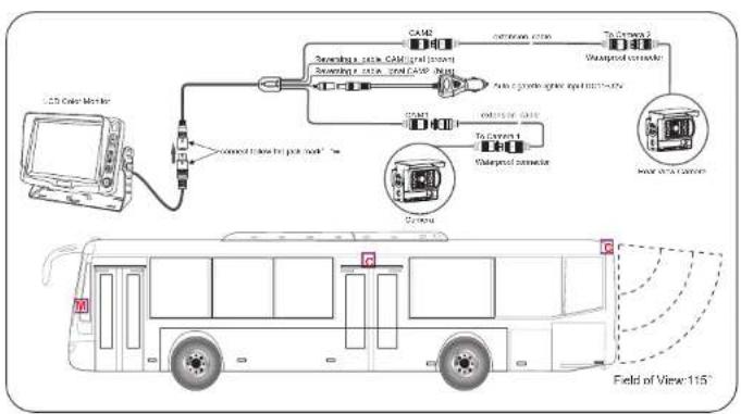
flowchart
graph TD
    A["CCS Cable Monitor"] --> B["Switching 1.0x CAM Signal"]
    B --> C["CAM"]
    C --> D["Switching 2.0x CAM Signal"]
    D --> E["To Camera 1"]
    E --> F["Switching 3.0x CAM Signal"]
    F --> G["To Camera 4"]
    G --> H["Switching 4.0x CAM Signal"]
    H --> I["To Camera 5"]
    I --> J["Switching 5.0x CAM Signal"]
    J --> K["To Camera 6"]
    K --> L["Switching 6.0x CAM Signal"]
    L --> M["To Camera 7"]
    M --> N["Switching 7.0x CAM Signal"]
    N --> O["To Camera 8"]
    O --> P["Switching 8.0x CAM Signal"]
    P --> Q["To Camera 9"]
    Q --> R["Switching 9.0x CAM Signal"]
    R --> S["To Camera 10"]
    S --> T["Switching 11.0x CAM Signal"]
    T --> U["Field of View 115°"]
MONITOR
II、Appearance and accessories
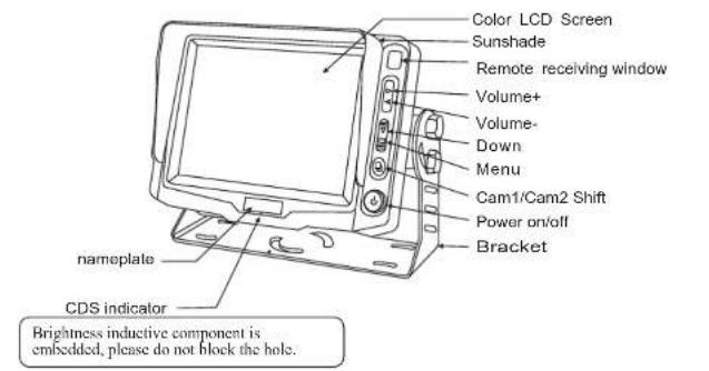
text_image
Color LCD Screen Sunshade Remote receiving window Volume+ Volume- Down Menu Cam1/Cam2 Shift Power on/off Bracket nameplate CDS indicator Brightness inductive component is embedded, please do not block the hole.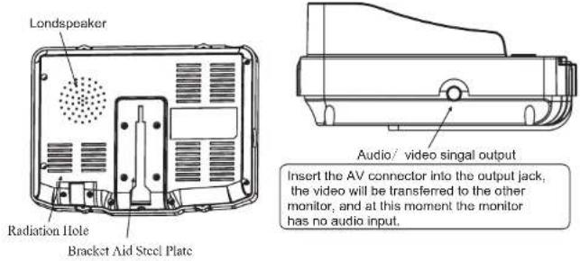
text_image
Londspeaker Radiation Hole Bracket Aid Steel Plate Audio/ video singal output Insert the AV connector into the output jack, the video will be transferred to the other monitor, and at this moment the monitor has no audio input.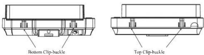
text_image
Bottom Clip-buckle Top Clip-buckleMONITOR
III、recautionsP
★ Storage and Keeping
 | Keep this machine away from too hot or too cold places. The storage temperature of this machine is 20~60 , the application temperature of this machine is 0~40 . | 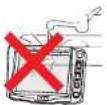 | Never use this machine near bathtub, wash basin, kitchen, etc places with water or at damp basementL swimming pool or similar places. |
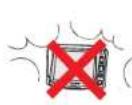 | Never make the TV set under afflection of moisture, dust or oil smoke etc. Environment. | 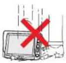 | Avoid this machine from dropping or impacting . |
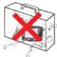 | Never put this machine within certain box at your will or place it at too oscillating place and under further severe collision. | 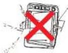 | Never extrude or frictionize this machine with sharp objects. |
Maintenance
Please plug off all connection wires before you start cleaning this machine.
 | Please wipe the machine cover, display screen and buttons with soft cloth dipped with little soft abluent. | 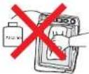 | Never wipe this machine with abrasion cloth, abstergent powder, alcohol and benzene etc. various propellants or chemical cleaning media. |
CAMERA
| CAMERA | COLOR CAMERACMOS | B/W CCD CAMERA | ||
| Image Pickup Device | 1/2 CMOS | 1/2"BW CCD | ||
| TV System | PAL | NTSC | CCIR | EIA |
| Image Size | 5.78mm×4.13mm | 4.9mm×3.7mm | ||
| Riceane Elements | 500(H)×582(V) | 510(H)×492(V) | 500(H) 582(V)× | 510(H) 492(V)× |
| Soaring Frequency | Horizontal:15.62kHzVertical Tube | Horizontal:15.7342kHzVertical Tube | Horizontal:15.62kHzVertical Tube | Horizontal:15.7342kHzVertical Tube |
| Horizontal Resolution | 330 TV Lines | 330 TV Lines | 420 TV Lines | 380 TV Lines |
| Minimum illumination | 1.0lux(2.0)+0 Lux At Night (IR LED ON) | |||
| Lens furnished | Board lens 2.9-8mm/F2.0(optional) | |||
| Electronic Suber Time | 1:50('180') 1/100,000(sec) | |||
| Gain control | Automatic | |||
| SN Ratio | More than 48bits | |||
| Sync system | Internal synchronization | |||
| White Balance | Automatic(2500K to 9500K) | |||
| r characteristics | 0.45 | |||
| Electronic Suber Control | Automatic | |||
| Wise Out | 1.0Vp-p 75 G | |||
CAMERA
IV、Technical Parameters
| CAMERA | COLOR CCD CAMERA | |||
| Image Pickup Device | 1/3"SHARP CCD | 1/4"SHARP CCD | ||
| TV System | PAL | NTSC | PAL | NTSC |
| Image Size | 4.8mm×3.7mm | 3.6mm×2.7mm | ||
| Picture Elements | 500(H) 582(V)×510(H) 492(V)× | 500(H) 582(V)×510(H) 492(V)× | ||
| Scanning Frequency | Horizontal 19.52kHzVertical: 5Hz | Vertical: 19.73GHzVertical: 90Hz | Horizontal 15.62kHzVertical: 50Hz | Horizontal 15.73kHzVertical: 60Hz |
| Horizontal Resolution | 420 TV Lines | 380 TV Lines | 420 TV Lines | 380 TV Lines |
| Minimum illumination | 1.0Lux(52.0):1.0 Lux At Night (IR LED ON) | |||
| Lens Furnished | Board lens 2.9-6mm(F2.0(optional) | |||
| Electronic Shutter Time | 1:50(1:50)-1:100,000(sec) | |||
| Gain control | Automatic | |||
| SN Ratio | More than 44ch | |||
| Sync system | Internal synchronization | |||
| White Balance | Automatic(2500K to 9500K) | |||
| s characters | 0.4s | |||
| Electronic Shutter Control | Automatic | |||
| Video Out | 1.0Vp-p 75.0 | |||
| CAMERA | COLOR CCD CAMERA | |||
| Image Pick-up Device | 1/3"SONY CCD | 1/4"SONY CCD | ||
| TV System | PAL | NTSC | PAL | NTSC |
| Image Size | 4.9mm×3.7mm | 3.8mm×2.7mm | ||
| Picture Elements | 500(H)×502(V) | 510(H)×492(V) | 500(H) 502(V)× | 510(H) 492(V)× |
| Searing Frequency | Horizontal 15/30kHz/Verita: 50Hz | Horizontal 1.0/30kHz/Verita: 60Hz | Horizontal 15/30kHz/Verita: 50Hz | Horizontal 15/30kHz/Verita: 60Hz |
| Horizontal Resolution | 420 TV Lines | 380 TV Lines | 420 TV Lines | 380 TV Lines |
| Minimum Illumination | 0.8lux(52.0)+0 Lux Air Night (R LED ON) | 0.8lux(52.0)+0 Lux Air Night (R LED ON) | ||
| Lens furnished | Board lens 2.9-8mm/F2.0(+optional) | |||
| Electronic Stutter Time | 1/50(1/60)-1/100,500(sec) | |||
| Gain control | Automatic | |||
| SIM Ratio | More than 48dB | |||
| Sync system | Internal synchronization | |||
| White Balance | Automatic(2600K to 6600K) | |||
| I characters | 0.45 | |||
| Electronic Stutter Control | Automatic | |||
| Video Out | 1.0Vp-p 75Ω | |||
MONITOR
IV、MENU OPERATION
Press to display options as following:
PICTURE CHANNEL OPTION SYS TEM
1、Picture
bright, Contrast, color and TINT displays on the screen as illustrated below
Press Down key before Rightight, press adjust the analog quantity of bright
from 0 to 100.
Press iDown key left to right color and TINT and press adjust the
analog quantity of contract, Color and TINT
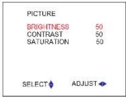
text_image
PICTURE BRIGHTNESS 50 CONTRAST 50 SATURATION 50 SELECT ADJUSTNote: Only when displaying the picture of NTSC system, it will show the character of TINT in the picture menu
2、channel choose
Cam1,Cam2,CH priority,CH delay,Delay time display on the screen as
illustrated below:
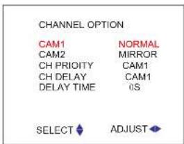
text_image
CHANNEL OPTION CAM1 NORMAL CAM2 MIRROR CH PRIORITY CAM1 CH DELAY CAM1 DELAY TIME OS SELECT ADJUSTPress Down key to select Cam1 or Cam2, press Left or Right to change image Mirror to Normal or normal to mirror.
Press Down key to select CH priority, press Left or Right to change Cam1 to Cam2 or Cam2 to Cams.
Press Down key to select CH delay, press Left or Right to choose Cam1 or Cam2 or both Came1 and Cam2 with delay function.
Press Down key to select delay time, press Left or Right to adjust the delay time from 0s to 30s
MONITOR
Attention: CH priority, CH delay and delay time only operate when backing the car. For example, Cam1 for CH priority, if both reversing signal cales with power in, the screen just displays picture from Cam1, otherwise it displays picture of Cam2. It can select Cam1 or Cam2 or both with delay function, if Cam1 for CH delay and the delay time is 10s, when backing the car (reversing cable of Cam1 power input) the screen will display picture of Cam1, but when you stop backing car, the screen still displays the picture of Cam1, it will back to original picture after 10s.
3、SYSTEM
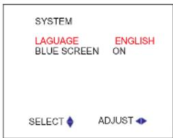
text_image
SYSTEM LAGUAGE ENGLISH BLUE SCREEN ON SELECT ADJUSTPress Down key to select language, press Left or Right to select language to Chinese or
English.
Press Down key to select blue screen, press Left or Right to select blue screen on or off
CAMERA
- Automatic clamshell rear view camera
| IR LED | 12 IR LED | |
| IR project distance | 15 meters | |
| Power supply | DC12/24V/500/250mA | |
| Dimension(mm) | 89(W) x 53(H) x 48(D) | |
| Weight | 450g |
CAMERA
III、camera appearance and dimension
- Car Backup Camera
| IR LED | 18 IR LED | |
| IR project distance | 15 meters | |
| Power supply | DC12V/250mA | |
| Dimension(mm) | 76mm×70mm×84mm | |
| Weight | 350g |
| IR LED | 18 IR LED | |
| IR project distance | 15 meters | |
| Power supply | DC12V/250mA | |
| Dimension(mm) | 80mm×63mm×70mm | |
| Weight | 350g |
| IR LED | NC | |
| IR project distance | NC | |
| Power supply | DC12V/50mA | |
| Dimension(mm) | 24mm × 78mm | |
| Weight | 180g |
| IR LED | 9 IR LED | |
| IR project distance | 5 meters | |
| Power supply | DC12V/120mA | |
| Dimension(mm) | 28mm × 42.5mm | |
| Weight | 88g |
| IR LED | NC | |
| IR project distance | NC | |
| Power supply | DC12V60mA | |
| Dimension(mm) | Φ26mm×31.5mm | |
| Weight | 65g |
| IR LED | NC | |
| IR project distance | NC | |
| Power supply | DC12V/80mA | |
| Dimension(mm) | 280mm×32mm | |
| Weight | 75g |
| IR LED | NC | |
| IR project distance | NC | |
| Power supply | DC12V/80mA | |
| Dimension(nm) | 68.5mm×45mm×41mm | |
| Weight | 80g |
| IR LED | 6 IR LED | |
| IR project distance | 5 meters | |
| Power supply | DC12V/150mA | |
| Dimension(mm) | 60mm×55mm×60mm | |
| Weight | 330g |
| IR LED | 8 IR LED | |
| IR project distance | 5 meters | |
| Power supply | DC12V/120mA | |
| Dimension(mm) | 48mm×45mm×54mm | |
| Weight | 300g |
| IR LED | 8 IR LED | |
| IR project distance | 5 melets | |
| Power supply | DC12W/120mA | |
| Dimension(mm) | 36mm × 74mm | |
| Weight | 240g |
| IR LED | NC | |
| IR project distance | NC | |
| Power supply | DC12V/50mA | |
| Dimension(mm) | 25mm × 41mm | |
| Weight | 80g |
| IR LED | NC | |
| IR project distance | NC | |
| Power supply | DC12V/50mA | |
| Dimension(mm) | 14mm × 42mm | |
| Weight | 100g |
| IR LED | NC | |
| IR project distance | NC | |
| Power supply | DC12V/50mA | |
| Dimension(mm) | 190mm×28mm×23mm | |
| Weight | 120g |
| IR LED | 12 IR LED | |
| IR project distance | 15 meters | |
| Power supply | DC12V/150mA | |
| Dimension(mm) | 62mm×95mm×100mm | |
| Weight | 120g |
MONITOR REMOTE CONTROL
1. Remote control appearance
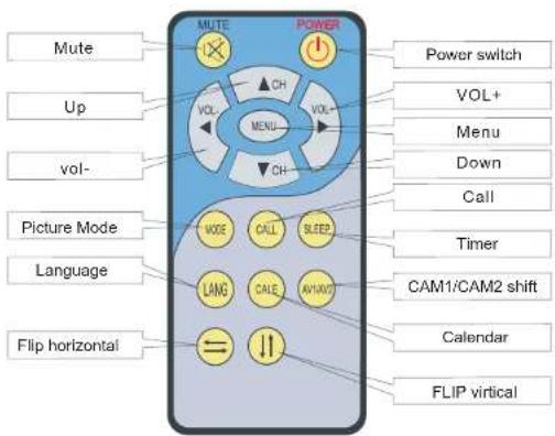
text_image
Mute Up vol- Picture Mode Language Flip horizontal MUTE POWER VOL+ Menu Down Call Timer CAM1/CAM2 shift Calendar FLIP virtual MODE CALL SLEEP LANG CALE AV/AV/7 Power switch VOL+II、Battery of the Remote Controller

text_image
② Puller ① EnterUsing the push button(CR2025)
MONITOR REMOTE CONTROL
III、Remote Control operation
MUTE:
Press this button, sound disappears, press it again or
VOL+/VOL- is to resume normal sound.
POWER:
Press this button is to turn off the monitor, press it again is to turn on the machine.
CH button(up/down)
press this button to select MENU mode.
VOL - / + (Volume adjust/analog quantity):
Press VOL -, the volume of Display -/analog quantity-.
Press VOL +, the volume of Display +/analog quantity+
Menu
Press this button to select MENU mode.
MODE:
Press this button, users can realize the five picture statuses of Standard,Soft, Vivid and light.
CALL:
Press this button is to display AV character currently watching
TIMER
Time setup of sleep off, it is used to set the time off within 120 minutes.
Language:
Press this button can realize the switch of Chinese, English.
AV1 / AV2 shift:
Press this button is to realize switch between Cam1 and Cam2 pictures.

Press this button is to flip the picture horizontally.

Press this button is to flip the picture vertically.
CAMERA
1. Characteristics of Rear View Camera
1 Alloy shell and 6.8G-force rated shock resistant.
2 High resolution and low power consumption.
3 Audio/Video signal output.
4 4pin aircraft grade weatherproof connector.
5 Wide angle and adjustable bracket.
6 Water resistance: IP66.
7 High intensity infrared night vision illuminator.
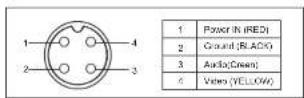
II. Sketch Map for 4-Pin Connector of Camer