Adora 662 (2012) - Caravan Adria - Free user manual and instructions
Find the device manual for free Adora 662 (2012) Adria in PDF.


User questions about Adora 662 (2012) Adria
0 question about this device. Answer the ones you know or ask your own.
Ask a new question about this device
Download the instructions for your Caravan in PDF format for free! Find your manual Adora 662 (2012) - Adria and take your electronic device back in hand. On this page are published all the documents necessary for the use of your device. Adora 662 (2012) by Adria.
USER MANUAL Adora 662 (2012) Adria
1 Foreword 2
2 Safety 4
3 Description & equipment 12
4 Placing into service 14
5 Before the journey 15
6 During the journey 24
7 After the journey 25
8 Living in the caravan 29
9 Sleeping arrangements 62
10 Power supply 68
11 Gas system 89
12 Water and waste water 95
13 Heater & hot water 100
14 Cooking 112
15 Refrigerator & freezer 118
16 Toilet 125
17 Winter camping 134
18 Placing out of service 137
19 Cleaning & care 141
20 Inspection & Maintenance 147
21 Troubleshooting 150
22 Technical Data 162
23 Checklists 169
Index 176
1 Foreword
You want to get to know new horizons? Count on us to help you!
Congratulations on your new ADRIA Caravan.
We have designed and built your caravan so that travelling with your "home away from home" will be very enjoyable.
1.1 Before your first journey
• Take your time and read this instruction manual on one of the comfortable seats of your caravan.
- This instruction manual also contains surprising innovations for experienced users because the ADRIA design team does not tolerate technical standstill.
- Pay special attention to the "Safety" Chapter (Chapter 2).
- Your own health and that of your passengers can depend on your familiarisation with the safety regulations and your adequate reaction to critical situations.
- Please also pay attention to the separate instruction manuals for special equipment and appliances as well as accessories.
- If your ADRIA caravan has special accessories, please observe the enclosed special approvals and the associated regulations.
1.2 Notes on this instruction manual
- Please understand that we reserve the right to alter the technical system, the form and the equipment. Our caravans are being continuously developed. Therefore, no claims can be made against ADRIA on the basis of the contents of these operating instructions. The equipment which was known and included at the time of going to press is described in this manual. This instruction manual is valid only insofar as the caravan corresponds to the state of the equipment described therein.
- The caravan models may have different equipment (standard equipment, special equipment and accessories). The standard equipment is described in this instruction manual. In this instruction manual, you will also find descriptions of the special equipment and accessories insofar as explanations are required. Please pay also attention to the enclosed separate instructions of the special equipment or accessory manufacturers.
- Reproduction, copying and translation, including extracts, are not permitted without the explicit approval of ADRIA. Misprints and errors excepted.
- ADRIA will not be held responsible for damage to the vehicle resulting from the nonobservance of the operating instructions.
© 2012 ADRIA
1.3 Warranty registration
In addition to these operating instructions, you will also find a Service and Warranty Booklet in your Adria caravan. Please perform the warranty registration as specified in the Service and Warranty Booklet.
1.4 Warranty, service and repair
- Please contact your local ADRIA dealer for all service and repair work as well as special questions.
– The employees of your authorised workshop will be pleased to provide advice and assistance. - Only original parts ensure the quality and operational readiness of your caravan.
– If service work is neglected or performed incorrectly, we will be unable to meet our warranty obligations according to our warranty conditions.
- Please fill in the following data of your caravan:
– These are of special significance when you have questions concerning ordering original parts.
- For the data of your caravan, see the nameplates.
| Vehicle data | |
| Model: | |
| Year of construction: | |
| Vehicle identification number: _ _ _ _ _ _ _ _ _ _ _ _ _ _ _ _ _ _ _ _ _ _ _ _ _ _ _ _ _ _ _ _ _ _ _ _ _ _ _ _ _ _ _ _ _ _ _ _ _ _ _ _ _ _ _ _ _ _ _ _ _ _ _ _ _ _ _ _ _ _ _ _ _ _ _ _ _ _ _ _ _ _ _ _ _ _ _ _ _ _ _ _ _ _ _ _ _ _ _ _ | |
| Bodywork key number: FW _ _ _ | |
Tab. 1 Vehicle data
We wish you unlimited enjoyment in your leisure time with your new ADRIA caravan.
Executive Board
2 Safety
2.1 Safety instructions
This Section contains safety instructions that must be followed when operating the vehicle.

Important!
We point out explicitly that we will not assume any liability for damage and malfunctions resulting from the nonobservance of this instruction manual.
2.1.1 Explanation of symbols

Danger!
Type of danger
▲ Avoidance
This type of safety warning warns of an imminently pending danger that could jeopardise the life and health of persons. Nonobservance of these safety instructions can cause severe damage to health up to life-threatening or fatal injuries.

Warning!
Type of danger
▲ Avoidance
This type of safety warning warns of a possible danger for persons. This type of warning must be exactly followed to prevent hazards to persons or severe material damage.

Caution!
Type of danger
▲ Avoidance
This type of safety warning warns of possible material damage. This type of warning must be exactly followed to prevent material damage.

Important!
Important
Notes of this kind provide additional information with respect to technical requirements. This type of information facilitates the handling of the vehicle for the user.
2.2 General safety instructions
- Safely store all objects before starting to drive. Securely close all flaps, doors, windows and hatches. Keep liquids in leak-proof containers.
- When staying in the vehicle, always keep the forced ventilation and the mushroom ventilator open and never covered, as there is a risk of suffocation by increased carbon monoxide.
• Always keep the instruction manuals for the vehicle and all installed appliances (e.g. cooker, refrigerator, toilet) and additional equipment (e.g. bike racks) in the vehicle and observe them. - Never leave children in the vehicle unattended.
- Pay attention to the vehicle height while driving.
- When leaving the vehicle, securely close all windows, doors and roof hoods.
- Pay attention to the clearance height of the entrance door.
2.3 Safety instructions for driving on public roads
• The vehicle muss be registered.
- The driver of the vehicle must have the required driving license.
- The installation of accessories changes the dimensions, the total weight as well as the road behaviour of the vehicle. Some of this equipment is subject to entry in the vehicle documents.
- When loading the vehicle, pay attention to the gross weight rating and the gross axle weight rating (see motor vehicle registration certificate, part I)
- Distribute the additional load evenly within the vehicle (Chapter 5.4).
- Check the tyre pressure and tighten the wheel nuts before starting to drive. Check the firm seating of the wheel nuts after 50 kph and then in regular intervals.
- Check the function of the brakes and the signal and lighting system.
• Empty the waste water tank.
- Close all doors, cupboard doors, drawers and flaps as well as all windows and roof hoods. Latch the refrigerator door securing device.
- Safely stow away loose pieces of equipment.
- Put the antennas in park position.
- Switch off the awning light.
- Retract the entrance step.
- Close and lock all outer doors and flaps.
- In winter, clear the roof from snow and ice before starting the journey.
- During the journey, persons or pets are not allowed to stay in the caravan.
- From a technical point of view, ADRIA caravans are designed for a permissible maximum speed of 100 kph. This maximum speed must not be exceeded, not even when a higher speed is allowed in the country being visited. Always pay attention to speed restrictions in individual countries which may be different..
- When parking the vehicle, apply the parking brake up to the maximum possible end position.
- Place wheel chocks in front of the wheels when parking the vehicle on inclines or slopes.
- Have the vehicle brake system checked and repaired by an authorised workshop only.
- When the vehicle is transported by rail or on a lorry, it must be loaded in the driving direction.
2.3.1 Driving with the caravan
- Drive according to your abilities taking the larger dimensions and the higher weight of the vehicle combination into consideration. You need time for familiarisation.
• Always take corners in a large radius and slowly. The cornering behaviour as compared with a passenger car changes because of the length of the car/caravan combination and its weight. - At driveways and crossings, the car/caravan acceleration is significantly lower than that of a passenger car.
- Due to the higher weight, the vehicle braking distance is much longer than that of a passenger car.
- Pay attention to the greater height of the vehicle at gateways and trees on the side of the road.
- When driving in reverse, always have a second person assist you.
- Due to the vehicle height, the vehicle is more sensitive to crosswind.
2.4 Official technical inspections
2.4.1 General inspection of caravan
As with any vehicle, the caravan must be officially inspected at regular intervals. For detailed information, see your Service and Warranty Booklet.

Important!
When driving in foreign countries, also pay attention to the regulations of the respective country.
2.4.2 Checking the gas system
The liquid gas system was inspected at the factory by a technical expert. The gas system must be inspected again every two years and after making any modifications and repairs. Always have a gas leak test performed on this occasion. The vehicle operator is responsible for initiating the inspection. Upon delivery of the vehicle, the operator must be informed in writing of his/her duty to have the gas system inspected. The correct condition of the gas system is confirmed with a gas inspection certificate and possibly, depending on national regulations, an associated gas inspection sticker.
2.5 Safety instructions for the gas system

Danger!
Poisoning by gas
▲ If it smells of gas or you suspect that gas is escaping, perform the following:
→ Clear the danger area!
→ Close the shut-off valve on the gas cylinder!
→ Avoid ignition sources and open flames and do not smoke!
→ Ventilate the rooms!
→ Inform the camping site manager, and the fire brigade when necessary!

Danger!
Risk of suffocation
▲ Never cover the forced ventilation in the roof hoods and in the floor area nor the mushroom ventilators in order to ensure continuous exchange of air in the vehicle.
Caution: Snowfall in winter!

Warning!
Injuries or material damage
▲ Subsequently installed, gas-operated additional appliances must be designed for an operating pressure of 30 mbar.
▲ The liquid gas system was inspected at the factory by a technical expert.
→ The gas system must be inspected again every two years and after making any modifications and repairs (Chapter 2.4.2).
→ Installations and modifications to the gas system may be performed only by an authorised workshop.
▲ The gas system may be put into service again only after inspection by a technical expert!
2.5.1 Gas stove

Danger!
Risk of suffocation
▲ In regular operation of the gas stove there exists acute danger to life due to lack of oxygen and the possibly generated odourless and toxic carbon monoxide (CO)!
▲ Always ensure good ventilation when the gas stove is in operation. Always keep a window, a roof hood or the doors open.
▲ Never use the gas stove for heating.

Danger!
Risk of poisoning
▲ If a flame of the gas stove extinguishes, unburned gas flows out for a short time until the flame failure device reacts and, together with the oxygen, generates an explosive mixture inside the vehicle!
▲ Watch the flames while using the burner!
▲ When finished, shut the respective quick-action stop valve.
2.5.2 Gas cylinder compartment
Check each time before using the gas:
→ Store the gas cylinders exclusively in the gas cylinder compartment. They must stand upright and fastened so that they are unable to turn or tilt.
→ The gas cylinder compartment must be sealed against the interior of the vehicle and must have a vent hole in or directly above the floor plate. This vent hole must have a minimum cross-section of 100 cm^2 and must not be covered.
→ Use only pressure regulators with safety valves! Other regulators are not allowed!
→ Carefully connect the regulator on the gas cylinder by hand. The screw connections on the gas regulator have left-hand threads. Do not use tools such as wrenches or pliers.
→ For temperatures below 5°C, a de-icing system for r regulators (e.g. accessory Eis-Ex) must be used.
Do not operate or store any current-storage devices (e.g. batteries) or devices that could be the source of ignition in the gas cylinder compartment.
→ Electric lines routed through the gas cylinder compartment have to be insulated and must not be connected with terminals; have the work performed by an authorised workshop.
→ Do not use the gas cylinder compartment as storage space.
→ Secure the gas cylinder compartment against unauthorised access.
2.5.3 Gas appliances in general
Pay attention to the following when operating the gas system:
→ The regulators and the exhaust gas routing must be inspected every two years! The inspection must be confirmed on the inspection certificate according to the DVGW [German Technical and Scientific Association on Gas and Water] worksheet G 607. The operator has to initiate the inspection.
→ The exhaust gas pipe must be fitted tightly to the gas heater and to the cowl, and must be sealed. It may not show any evidence of damage.
→ The exhaust gas routing of the gas heater must be installed ascending over its complete length and fitted tightly with clamps. If required, install exhaust gas pipe supports.
→ Before placing the gas heater into service, always clear dirt and snow from the cowl and combustion air inlets. This prevents increased, unacceptable carbon monoxide content in the exhaust gas.
→ Radiant heaters and appliances drawing combustion air from the interior of the vehicle are not to be used for heating the vehicle!
→ When gas appliances are switched on that require the control knob to be pressed for lighting (e.g. gas stove), it must spring back automatically immediately after release.
→ If no gas is being consumed during the journey, the shut-off valves on the gas cylinders must be closed.
→ Close the respective quick-action stop valve when gas-operated appliances are not used.
→ Close the shut-off valve on the gas cylinder when the vehicle will not be used for a longer period.
→ Operate the gas system only with propane gas, butane gas or a mixture of both. Propane gas is capable of gasification down to -32^ , whereas butane gas gasifies only to approx. 0^ .
→ Gas appliances are not to be operated during refuelling, in a garage or on a ferry.
→ Observe the relevant regulations in foreign countries!
2.6 Safety instructions for the electrical system
Pay attention to the following when operating the electrical system:
→ Installations and modifications of the electrical system have to be performed by qualified personnel.
→ Prior to carrying out work on the electrical system, switch off all appliances and lights, disconnect the battery and disconnect the 230 V power cable from the mains.
→ Replace defective fuses only when the cause of the defect is known and has been remedied. Use only original fuses with the values specified in the instruction manual from the respective manufacturer.
→ Do not bridge or repair fuses.
2.7 Fire prevention
2.7.1 General fire prevention

Danger!
Fire risk
▲ Only authorised and qualified personnel may perform service work and modifications to the gas system and the electrical system.
▲ Never leave children in the vehicle unattended.
▲ Do not use portable heating or cooking appliances.
▲ Keep flammable materials clear of cooking and heating appliances.
▲ Acquaint yourself with the position and operation of the emergency exits in the vehicle.
▲ Always keep escape routes clear.
▲ Empty ashtrays into the waste bin only when the ashes are cold.

Important!
Always have a dry powder fire extinguisher (special accessory) filled with 1 kg minimum in your vehicle.
→ The fire extinguisher must be close at hand.
→ Read the instruction manual carefully and keep it close at hand.
→ Have the fire extinguisher checked at regular intervals by qualified personnel; observe the test seal.
2.7.2 What to do in the case of fire
Correct behaviour:
→ Evacuate all passengers.
→ Close the shut-off valve on the gas cylinder.
→ Switch off the electrical power supply; disconnect the vehicle from the mains.
→ Call the fire brigade, sound the alarm.
→ Fight the fire, if possible.
2.8 Safety instructions for the roof

Warning!
Risk of injury and damage to the vehicle roof
▲ The roof of the vehicle is not designed for the weight of standing persons.
▲ The roof of the vehicle is not capable of supporting walking persons.
▲ Clear snow and ice from the roof and from the roof hoods.
→ Use a ladder which is placed against the roof edge for this purpose.
2.9 Safety instructions for rear carrier systems (special accessories)

Warning!
Risk of injury and damage to the vehicle
▲ Pay attention to the statutory regulations for the installation of a rear carrier.
▲ When the rear lighting of the vehicle is covered, a second set of lights must be installed.
▲ Do not exceed the permissible carrying weight of the rear carrier.
▲ The load must not project by more than 40 cm on the sides. Do not allow sharp or pointed objects to project.
▲ The load must be stored safely and specially secured against falling down.
▲ When the rear carrier is used, the load distribution of the vehicle as well as its drive and brake behaviour change.

Important!
Have the installation of a rear carrier performed by an authorised workshop only. Ask your ADRIA dealer for advice.
2.10 Environmental tips
For the protection of our environment, always pay attention to the following:
→ Always turn off the engine when the vehicle stands still. The operating temperature is reached most quickly while driving.
→ Never dispose of any kind of waste water and waste in the open countryside.
→ Empty the waste water tank and the toilet only at special waste disposal stations. These waste disposal stations are available at camping sites. Request information from local authorities.
→ Use environmentally-friendly chemical additives for the toilet.
→ Separate household waste and dispose of this waste in special waste disposal stations.
→ When staying in towns and communities for longer periods, always stay at camping sites. Obtain information about car parks and camping sites in time before starting the journey.
→ Always collect waste oil, lubricants and cleaning agent in suitable containers and dispose of them properly.
3 Description & equipment
3.1 About this instruction manual
In the diagrams for explanation of the equipment, "black arrows" always stand for switching off or closing an equipment part and "white arrows" for switching on or opening.
3.2 Bodywork
The bodywork of the vehicle is made in "sandwich construction". The "sandwich" structure consists of 3 layers with a total thickness of up to 40 mm:
- Outer skin: Polyester (glass-fibre reinforced plastic) or aluminium
• Insulation: Styrofoam - Inner wall: Wooden panels
The 3 layers are glued with special adhesive which penetrates in the styrofoam and ensures the bonding of the layers. This layer structure provides optimum heat insulation of the vehicle.
To improve road safety, a 3rd brake light is installed in the upper rear area.
3.3 Gas cylinder compartment
The lockable gas cylinder compartment is sealed and insulated with respect to the interior (Chapter 11.2).
3.4 Interior furnishings
All pieces of furniture are made from high-quality materials and securely attached. Sufficient storage space is available in the living area and in the kitchen unit.
The furniture surfaces can be easily cleaned with commercially available cleaning agents (Chapter 19.2).
Depending on the model, the vehicle has firmly installed beds and/or seating groups that can be easily converted for sleeping. (Chapter 9).
3.5 Kitchen
The kitchen unit consists of cooking stove, oven (special equipment), microwave oven (special equipment), sink and a refrigerator/freezer (Chapter 14).
Adequate storage space is provided.
An exhaust hood with or without lighting above the kitchen unit is available as special equipment.
3.6 Bathroom unit
Each vehicle contains a bathroom unit (Chapter 8.10) with sink, toilet (Chapter 16) and, depending on the layout plan, also a shower. The folding door, swinging door or curtain must be closed when taking a shower (Chapter 8.10).
3.7 Heater
The vehicle has - in some cases as special equipment - a heater with hot-air blower or warm water heater (Chapter 13).
3.8 Water and waste water
The vehicle is equipped with a water tank, and possibly as special equipment, with a waste water tank (Chapter 12).
4 Placing into service
4.1 Registering the vehicle
Before the first journey, the vehicle must be registered according to national regulations and a license plate fitted. Vehicles may be operated in road traffic only when insurance cover exists. An EC approval exists for the vehicle.
4.2 Placing the vehicle into service for the first time

Warning!
Make sure to follow the safety instructions
▲ Carefully read and follow the safety instructions (Chapter 2.1) before placing the vehicle into service.
▲ Insurance coverage and warranty claims to the manufacturer become void when the safety instructions are not observed and followed.

Warning!
Accident hazard
▲ After the first 50 km, retighten the wheel nuts and then regularly check the seating of the wheel nuts.
▲ Check the tyre pressure before each journey.
Pay attention to the following when placing the vehicle into service:
→ Familiarise yourself with your vehicle before the first journey.
→ Get used to the driving characteristics and dimensions of your vehicle during a short weekend trip.
→ Drive slowly and carefully in the beginning.
5 Before the journey
5.1 Wheel arch insert

Warning!
Danger of injuries from parts flying around
▲ Remove the wheel arch inserts before driving with the caravan and stow them away safely.
5.2 Coupling the caravan

Warning!
Risk of injury when coupling and manoeuvring
▲ Make sure nobody is between the towing vehicle and caravan when manoeuvring and coupling.

Caution!
Risk of damage to the coupling
▲ Do not couple or uncouple the caravan with the overrun device shaft pressed in.
▲ Observe the maximum allowable nose weight and the maximum allowable rear axle load of the towing vehicle. Refer to the vehicle documents belonging to the towing vehicle and the caravan for the allowable limits. These must not be exceeded.
▲ Do not use the stabilizer lever on couplings as manoeuvring assistance (if fitted).
▲ Do not grease friction pads. Greasy friction pads cannot create the weaving stabilizing effect. This weaving stabilizing effect is only ensured when the tow ball on the towing vehicle is kept clean and free from grease.
→ Do not lubricate the cup of the AKS safety coupling.
→ Do not lubricate the ball on the tow bar.
→ Make sure the friction pads remain free from oil and grease when lubricating moving parts of the safety coupling.
→ Couple the caravan. The tow ball and cup must grip each other and not just lay over each other. The cup must clamp the complete tow ball.
→ Hang the breakaway cable around the ball head of the tow ball or in the fastening lug of the towing vehicle when using a removable tow bar. Always check the cable length: A longer cable must not drag on the ground and apply the brakes. A shorter cable must not apply the brakes when going around corners.
→ Crank the jockey wheel in completely and then pull it up as high as possible in the mounting. Position the running wheel parallel to the driving direction and pointing towards the towing vehicle.
→ Connect the light/power plug to the socket of the towing vehicle. Make sure the plug locks in properly.
→ Run the light/power supply cable in a loose loop over the coupling. Make sure the cable does not drag on the ground and is not tensioned.
→ Make sure the ball of the tow bar is locked completely in the coupling. The green safety marking on the coupling must be visible.
→ Check that all corner steadies have been fully raised.
→ Check the caravan lights when the towing vehicle is coupled.
5.2.1 Couplings

Warning!
Risk of weaving
▲ Before coupling, make sure the tow ball on the towing vehicle is free from oil and grease.
▲ Clean off any dirt before coupling.
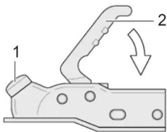
5.2.1.1 Couplings AK 150 V/160/200 V/251 S/300
text_image
1 210100016
Fig. 1 Couplings AK 300 and AK 160
1 Safety marking
2 Coupling grip
The coupling mechanism has an "open" position which means the coupling remains open until the tow ball locks completely into the cup.
Coupling the vehicle:
→ Check that the coupling is open.
→ Position the open coupling Fig. 1) onto the tow ball of the towing vehicle until it fully engages with a click.
→ To help, press the coupling grip (Fig. 1/2) down by hand.
→ Check that the safety marking (green band) (Fig. 1/1) is visible.
For more information, see the separate instructions from the manufacturer.
5.2.1.2 Coupling AKS 1300
text_image
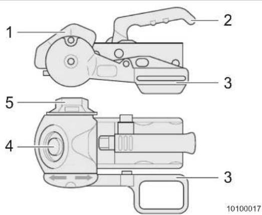
1 2 3 5 4 3 10100017Fig. 2 Coupling AKS 1300
1 "Locked" marking
2 Coupling grip
3 Stabilizer lever
4 Safety marking
5 Handwheel
Coupling the vehicle:
→ Move the stabilizer lever (Fig. 2/3) fitted at the side up to the top position.
→ Turn the handwheel (Fig. 2/5) anticlockwise to the stop and open completely.
→ Pull the coupling grip (Fig. 2/2) straight up.
→ Position the open coupling onto the tow ball until the coupling grip locks in with a click. The coupling grip moves back to the start position on its own.
→ To help, press the coupling grip (Fig. 2/2) down by hand.
→ Check that the safety marking (green point) (Fig. 2/4) is visible.
→ Turn the handwheel clockwise until the torque limiter slips noticeably and audibly.
→ Press the stabilizer lever down to the lowest position. The marking on the stabilizer lever must be positioned directly below the "locked" marking (Fig. 2/1) of the stabilizer housing.
For more information, see the separate instructions from the manufacturer.
5.2.1.3 Coupling AKS 3004
text_image
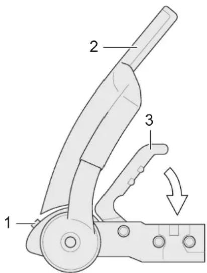
Technical diagram of a mechanical device with numbered parts and directional arrow indicating motion or movement1 Safety marking
2 Stabilizer lever
3 Coupling grip
Fig. 3 Coupling AKS 3004
Coupling the vehicle:
→ Move the stabilizer lever up (Fig. 3/2) to the top position.
→ Pull the coupling grip (Fig. 3/3) upwards and open the coupling.
→ Position the open coupling onto the tow ball until the coupling grip locks in with a click. The coupling grip moves back to the start position on its own.
→ To help, press the coupling grip (Fig. 3/3) down by hand.
→ Check that the safety marking (green band) (Fig. 3/1) is visible.
→ Press the stabilizer lever (Fig. 3/2) down to the lowest position.
For more information, see the separate instructions from the manufacturer.
5.2.2 Coupling BPW WS 3000 D
text_image
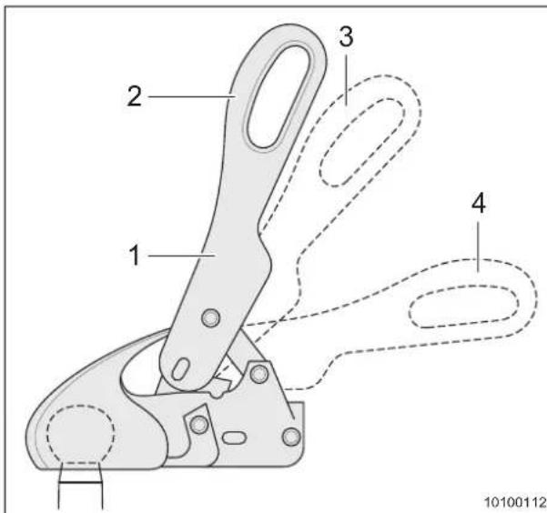
1 2 3 4 10100112Fig. 4 Coupling BPW WS 3000 D
1 Stabilizer lever
2 Uncoupling position
3 Coupling position
4 Stabilizer device active
Coupling the vehicle:
→ Move the stabilizer lever (Fig. 4/1) to the uncoupling position (Fig. 4/2).
→ Position the open coupling onto the tow ball and, if necessary, press down by hand until the coupling grip locks in with a click. The stabilizer handle moves approx. 10° down to the coupling position (Fig. 4/3).
To activate the stabilizer device, press the stabilizer lever (Fig. 4/1) down to the bottom, horizontal position (Fig. 4/4) to the stop.
→ Check that the tow ball is completely retracted and not visible when coupled.
For more information, see the separate instructions from the manufacturer.
5.3 Uncoupling the caravan

Warning!
Risk of injury during uncoupling
▲ Always apply the parking brake before uncoupling.
▲ Secure the vehicle against rolling away before uncoupling the vehicle.
Uncoupling the vehicle:
→ Apply the caravan parking brake.
→ Secure the vehicle against rolling away with wheel chocks.
→ Disconnect the light/power supply plug from the towing vehicle socket and secure safely.
→ Release the overrun brake cable from the tow bracket on the towing vehicle.
→ Crank the jockey wheel down. The wheel must be firmly on the ground.
→ If necessary, also open the stabilizer lever of the stabilizer device.
→ Stretch the overrun device, drive the towing vehicle slightly away when necessary, until the folding bellow over the overrun device is no longer pressed together.
→ Release the coupling with the hand grip. Use the jockey wheel to lift the coupling from the tow ball until the ball is completely free.
→ Drive the towing vehicle away.
5.4 Loading the vehicle

Warning!
Risk of injury and severe damage to the vehicle
▲ When a tyre bursts, the vehicle can get out of control.
▲ Do not exceed the vehicle gross weight rating.
▲ Check the tyre pressure (Chapter 22.1) at regular intervals. Tyres can burst when the tyre pressure is too low.

Warning!
Danger of overloading
▲ The gross weight rating entered in the vehicle documents must not be exceeded. Tyres can also burst when the vehicle is overloaded.
▲ A warranty claim to the manufacturer and the insurance coverage become void.
Pay attention to the following when loading the vehicle:
- Unladen weight = mass in ready-to-drive condition according to EN 1646-2 (Chapter 22.2).
- Additional equipment installed in the factory and options increase the unladen weight and reduce the additional load.
- Determine the maximum additional load according to part 1 of the registration certificate and the list in the "Technical data" Chapter (as from Chapter 22.2).
- The additional load refers to the luggage.
- On vehicles with standard equipment, the outside of the roof and the rear area are not to be loaded.
- Never exceed a height of 4m and a width of 2.55m with additional attachments.
- Attach and secure the roof and rear loads so that they do not slip, are unaffected by the wind and are streamlined. Do not use rubber expanders!
- In order not to endanger other road users, objects must not project beyond the vehicle silhouette on the side or rear.
- Do not overload the vehicle. For weight information and Tables, see Chapter 22.2 and the registration certificate, part I.
- Pay attention to the correct axle load distribution. Roadability and tyre wear are directly affected by the axle load. Pay attention to the maximum axle loads (see registration certificate part I).
- Load the vehicle evenly on the right and left. The driving characteristics deteriorate when loading is uneven.
- Store heavy objects (e.g. tinned food, cutlery, dishes) in low-lying storage compartments and secure them against slipping.
- Stack light objects, e.g. clothes, in higher storage compartments or in the compartments below the seats.
• Always keep liquids in leak-proof containers in low-lying storage compartments.
- Load the bike rack (special accessory) with only 2 bikes at the most (50 kg maximum).
i Important!
Weigh the completely loaded vehicle on public scales before starting your journey.
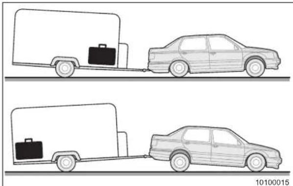
natural_image
Two identical illustrations of a cargo truck with a briefcase, connected by a trailer to a sedan (no text or symbols)Fig. 5 Caravan load spread incorrect
CARAVAN LOAD SPREAD INCOR- RECT!
• Caravan weaves dangerously
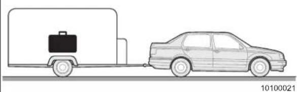
natural_image
Line drawing of a car parked next to a truck with a briefcase (no text or symbols)Fig. 6 Caravan load spread correct
CARAVAN LOAD SPREAD COR- RECT!
- Whenever possible, store objects over the axle(s).
- Store heavy objects at lower positions.
- Store light objects at upper positions.
i Important!
Pay attention to the following when installing rear carriers:
- Attachment and securing of the load as specified
- Allowable load-carrying capacity of the vehicle and axle(s)
- Change of driving and braking behaviour of the vehicle
• Change of overall length
5.5 Additional rear view mirrors

Warning!
Accident hazard
▲ Never reverse without adequate field of view towards the rear. Use additional rear view mirrors!
▲ Check additional rear view mirrors are set correctly before driving.

Important!
Additional rear view mirrors must meet EU Directives and must be EU type-tested.
Two rear view mirrors must be fitted on towing vehicles when towing. The rear view mirrors must provide an adequate field of view along the side and behind the towed vehicle.
Fit rear view mirrors with adequate fastening to prevent strong vibrations affecting the field of view.
5.6 Tyres

Warning!
Risk of injury and severe damage to the vehicle
▲ When a tyre bursts, the vehicle can get out of control.
→ Check the tyre pressure (see Tab. 26 in Chapter 22) at regular intervals.
→ Check the tyres for damage at regular intervals
→ Comply with minimum tread depth. Observe the regulations of the respective country.
- Regularly check the tyre pressure on cold tyres and correct the tyre pressure as required. Do not forget the spare wheel (special equipment).
- The tyres overheat if the tyre pressure is too low which can cause the tyres to burst at high speed.
- Check the tyres for even wear and damage at regular intervals (e.g. penetrated foreign objects, punctures, cuts, tears and bumps in the tyre sidewalls). Always have the damage repaired by a specialist.
- Regularly check the tread depth.
- If the tread depth is too small, the risk of aquaplaning rises.
- Comply with the minimum tread depth. Observe the regulations of the respective country. We recommend to change the tyre as from a tread depth of 4mm .
- Always use tyres of the same construction, same brand and same type (summer and winter tyres). Do not forget the spare wheel (see Tab. 26 in Chapter 22).
- Regularly check the wheel nuts or bolts for firm seating.
- When the vehicle is put out of service for a longer period, prevent "flat spots" on the tyres.
- Relieve the load on the tyres by jacking up the vehicle.
- Move the vehicle every 4 weeks so that the position of the wheels is changed and the load on the tyres is always at different positions.
- Increase the tyre pressure by 0.3 bar as compared with the stipulated tyre pressure.
- Drive over kerbs slowly and, if possible, at an obtuse angle. Avoid driving over steep and sharp-edged kerbs.
- Hard or acute-angled impacts against kerbs or sharp-edged objects, for example stones, can damage the tyres.
- Drive over high manhole covers at a slow speed.
- Hidden tyre damage is not eliminated by correcting the tyre pressure.
- Do not use used tyres.
– Tyres age even when they are not driven or driven only a little.
- It is recommended to change the tyres of the vehicle, including the spare wheel, when they are 6 years old or earlier when the minimum tread depth is reached.
5.7 Electrical lighting
Before starting to drive, check the function of all interior and exterior lighting equipment on the vehicle and replace defective lighting elements.
Make yourself familiar with the replacement of the lighting elements before starting to drive (Chapter 21).
5.8 Spare keys
The following information is required for ordering a spare key:
| Key for Required information To be obtained from | ||
| Bodywork (doors and flaps) | • Vehicle identification number: • Registration certificate part II • Key number | Adria Service department |
Tab. 2 Spare keys
5.9 General check before starting to drive

Warning!
Danger of injuries from parts flying around
▲ the wheel arch inserts before driving with the caravan and stow them away safely.

Warning!
Hazards and damage due to unsecured load
▲ After having driven for a few kilometres, check the additional load is stowed in slip-free manner in the vehicle.
Go through the checklists (Chapter 23) before starting to drive.
6 During the journey

Caution!
Risk of injury and damage to the vehicle
▲ During positioning manoeuvres, when driving through passageways, bridges, tunnels and with overhanging branches, observe the dimensions of the vehicle.
▲ Dimensions of the vehicle, see vehicle documents.
▲ Equipment and attachments change the weight and the dimensions.
▲ From a technical point of view, ADRIA caravans are designed for a permissible maximum speed of 100 kph. This maximum speed must not be exceeded, not even when a higher speed is allowed in the country being visited. Always pay attention to speed restrictions in individual countries which may be different.

Important!
- During the journey, persons or pets are not allowed to stay in the caravan.
Pay attention to the following during the journey:
→ When starting to drive and at low speed, check the function of the brake system and the brake behaviour (directional stability, function of overrun brake, etc.) by braking shortly.
→ Adjust your driving technique to the vehicle size, drive with consideration and foresight.
→ Drive slowly on poor roads.
→ Drive downhill at the same speed as uphill.
→ Switch to the next gear early enough.
→ Avoid braking abruptly.
→ Prevent jerky steering as this could cause the car/caravan combination to weave.
→ When driving over bridges, you have to anticipate crosswind. Because of the vehicle size and height, a caravan is more sensitive to crosswind than a passenger car.
→ When overtaking truck-trailer combinations, the car/caravan combination can get into a turbulence. Light counter-steering compensates this effect.
→ Do not underestimate the length of the car/caravan combination.
→ When turning into a road and when driving around bends, take the larger curve radius of the car/caravan combination into consideration.
→ The braking distance of a car/caravan combination is considerably longer than that of a passenger car. Please increase the safe distance accordingly.
→ When driving in reverse, always have a second person assist you because the rear view mirrors can distort the distances differently.
→ At petrol stations or in garages, switch off all "open flames" operated with gas (also refrigerator or heater).
7 After the journey
7.1 Requirements to the parking area
The parking area should be firm and level.
7.2 Pitching the caravan
A second person is helpful for the following tasks.
Aligning the vehicle:
→ Align the caravan horizontally crosswise to the driving direction. If this is not possible, use drive-on chocks underneath the respective wheels or, if sufficient room is available, move the caravan until you have found a horizontal position.
→ Align the caravan horizontally by adjusting the jockey wheel in driving direction.
→ Firmly apply the parking brake.
→ Secure the caravan with the wheel chocks against rolling away.
→ To prevent swaying of the caravan, always extend all corner steadies on the vehicle. The crank can be found in the storage space that is accessible from the outside.
7.2.1 Corner steadies

Warning!
Damage to vehicle
▲ Crank up the corner steadies completely before starting to drive. When starting to drive, the chassis or the vehicle bottom could be damaged by extended corner steadies.
▲ Torn off corner steadies could jeopardise other road users.

Caution!
Damage to vehicle frame
▲ Do not use the corner steadies for lifting the vehicle. This could result in distortion of chassis and bodywork.
To prevent the vehicle from unnecessary swaying at its parking location, we recommend extending the corner steadies on the vehicle.
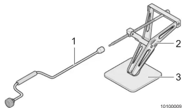
text_image
1 2 3 10100009Fig. 7 Corner steady
1 Crank
2 Corner steady
3 Base
Extending the corner steady:
→ Place the crank (Fig. 7/1) against the corner steady (Fig. 7/2).
→ Turn the crank anticlockwise to extend the corner steady.

Important!
- Place a firm substructure (Fig. 7/3) underneath the base (Fig. 7/2) of the corner steadies when your vehicle is standing on soft ground such as grass or sand. This prevents sinking into the ground and facilitates the retraction of the corner steadies before starting to drive again.
7.2.2 Electrical connection
If 230 V supply is available at your parking area, the electrical appliances can be connected to this voltage supply (Chapter 10.1.1).
Observe the fuse protection of the voltage supply.
If there is no 230 V supply, individual appliances can be operated via the 12 V supply of the towing vehicle. The 12 V supply works only when the towing vehicle is connected to the caravan and the ignition of the towing vehicle is switched on.
Some vehicles have their own living area battery (special equipment). On these vehicles, electric consumers can also be operated without connection of a towing vehicle.
7.2.3 Entrance step

Warning!
Risk of injury
▲ Make sure to place the entrance step only on safe ground.
▲ Do not step on the edge of the entrance step.
▲ Fasten the entrance step on the ground.
→ Place the entrance step in front of the vehicle entrance door.
7.3 Electrical entrance step (special equipment)
Some vehicles are equipped with an electrical entrance step.

Warning!
Accident hazard
▲ Maximum load of entrance step: 200 kg.
▲ Only use the step when it is fully extended.
▲ Before starting the journey, ensure the entrance step is completely retracted.
▲ Extend and retract the entrance step only in an unloaded condition.
▲ Keep persons and pets away from the entrance step during extension or retraction.
▲ Only adults may operate the entrance step.
▲ Never leave the vehicle without extended entrance step.
▲ Never jump on the step.
▲ Only one person may be on the step at a time.
▲ Before extending or retracting the entrance step, check the available space.
▲ Ensure the extended step does not represent an obstacle or hazard for third persons.
▲ In adverse weather conditions, clean the step from snow or ice.
▲ Clean the entrance step thoroughly at regular intervals to ensure its perfect function.
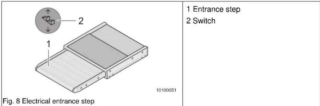
Retracting or extending the electrical entrance step:
The switch (Fig. 8/2) for retraction or extension of the entrance step is located in the entrance area near the outer door.
→ Tip the switch (Fig. 8/2) briefly in the lower area until the entrance step is extended (Fig. 8/1).
→ Tip the switch (Fig. 8/2) briefly in the upper area until the entrance step is retracted (Fig. 8/1).
7.4 Waste water tank, mobile (special equipment)
Store the waste water tank (Fig. 9/1) in the gas cylinder compartment of the caravan during the journey.
The drain pipe (Fig. 9/2) is located on the vehicle underside on the left in driving direction.
Observe the following before using the water system:
→ Open the cap of the waste water tank and stow away safely.
→ Place the waste water tank (Fig. 9/1) under the drain pipe (Fig. 9/2) so that no water is drained outside the waste water tank.
→ Check the level of the waste water tank at regular intervals and dispose of waste water in time at an approved drain.
8 Living in the caravan
8.1 Entrance door
8.1.1 Opening / closing the door from the outside
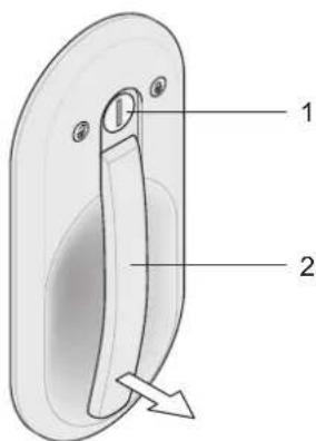
text_image
1 2Fig. 10 Opening / closing the entrance door from the outside
1 Door lock
2 Door handle
Opening the door:
→ Insert the key into the door lock (Fig. 10/1) and turn towards the "open lock" symbol to the stop.
→ When released, the key returns to the initial position.
→ Remove the key.
→ Pull the door handle (Fig. 10/2) to open the door.
Closing the door:
→ Close the door until the door lock latches.
→ Insert the key into the door lock (Fig. 10/1).
→ Turn the key anticlockwise to the stop. If necessary, push the door lightly into the seals. When released, the key returns to the initial position.
→ Remove the key.
natural_image
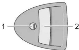
Simple diagram of a curved object with labeled parts 1 and 2, no text or symbols present.Fig. 11 Opening / closing the entrance door from the outside
1 Door lock
2 Door handle
Opening the door:
→ Insert the key into the door lock (Fig. 11/1) and turn into the direction of the hinge side of the door to the stop.
When released, the key returns to the initial position.
→ Remove the key.
→ Pull the door handle (Fig. 11/2) to open the door.
Closing the door:
→ Close the door until the door lock latches.
→ Insert the key into the door lock (Fig. 11/1).
→ Turn the key anticlockwise to the stop. If necessary, push the door lightly into the seals. When released, the key returns to the initial position.
→ Remove the key.
8.1.2 Opening / closing the door from the inside

text_image
Technical diagram of a mechanical component with numbered parts and directional arrow indicating motion or forceFig. 12 Opening / closing the entrance door from the inside
1 Door handle
2 Door opener
3 Locking button
Opening / closing the door:
→ Operate the door opener (Fig. 12/2) and open the door.
→ When released, the door opener (Fig. 12/2) returns to its initial position.
→ To close the door, pull the door handle (Fig. 12/1).
Locking the door:
→ The locking button (Fig. 12/3) is at the top of the door handle (Fig. 12/1).
→ To lock the door, push the locking button (Fig. 12/3) down into the door handle (Fig. 12/1).
text_image
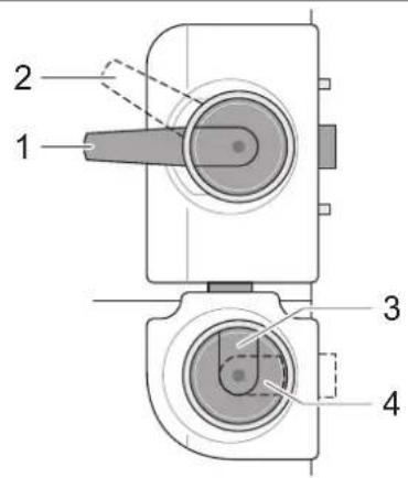
1 2 3 4Fig. 13 Opening / closing the entrance door from the inside
1 Door handle (door unlocked)
2 Door handle (door locked)
3 Locking latch
Opening / closing the door:
→ Push the door handle (Fig. 13/1) down and open the door.
→ When released, the door handle (Fig. 13/1) returns to its initial position.
→ To close the door, pull the door handle (Fig. 13/1).
Locking the door:
→ Pull the door handle (Fig. 13/1) upwards into locking position (Fig. 13/2). The door is locked and can be opened from the outside only with the key.
Separating/locking the two-part door (special equipment):
→ Close the door.
→ Turn the locking latch (Fig. 13/3) to horizontal position (Fig. 13/4).
The upper part of the door is unlocked and the lower part of the door is locked at the same time.
→ Turn the locking latch (Fig. 13/3) to vertical position again for opening.
8.1.3 Door arrester
text_image
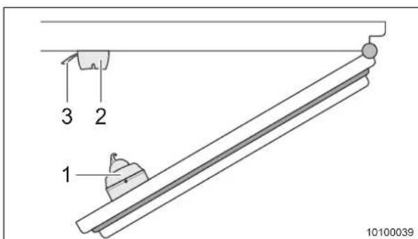
1 2 3 10100039Fig. 14 Door arrester, 2-part
1 Door part
2 Holder part
3 Holder
Releasing the door arrester
→ Pull the holder (Fig. 14/3) at the holder part (Fig. 14/2) of the door arrester.
→ Pull the door part (Fig. 14/1) with the door out of the holder part.
8.2 Ventilation of caravan

Danger!
Poisoning by gas and carbon monoxide
▲ Always keep the forced ventilation (in the roof hoods and in the floor panel) and the mushroom ventilators open, do not cover them.

Caution!
Possibility of mould formation
At night, condensation water could collect under the cushions. To dry the cushions (foamed material), place the cushions in an upright position and ventilate the vehicle thoroughly.
- The correct ventilation of the caravan is the best prerequisite for agreeable living comfort.
• Each person gives off up to 35 g water per hour by breathing. Therefore, the caravan must be ventilated depending on the relative humidity via the windows and roof hoods.
• Additional water evaporates as a result of cooking or wet clothes. - Extreme weather conditions could cause the forming of condensed water inside the acrylic glass double window. With rising temperatures, the condensation water evaporates again and the window is cleared.
For more information see Chapter 17 on winter camping.
8.3 Hinged windows
8.3.1 General
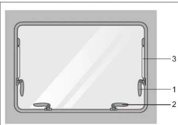
The hinged windows of the caravan have a locking device, i.e. the hinged window automatically locks into place in the desired position after opening.
The number of locking levers at the bottom edge of the window varies depending on the window width.
text_image
1 2 3Fig. 15 Hinged windows
1 Locking lever on hold-open hinge
2 Locking lever at bottom edge of window
3 Hold-open hinge
Opening the window:
→ Open the two locking levers (Fig. 15/1) on the hold-open hinges (Fig. 15/3) first.
→ Then open the locking levers (Fig. 15/2) on the bottom edge of the window.
→ Push the window to the outside until it has the desired opening width.
Closing the window:
→ With automatic hold-open hinges, open the window until the lock is released.
→ First close the locking levers on the bottom edge of the window.
→ Afterwards, close the locking levers on the hold-open hinges.
8.3.2 Opening/closing the windows
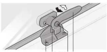
To open and close the hinged windows, open or close all locking levers on the respective hinged window.
natural_image
Mechanical assembly diagram showing a lever mechanism with mounting points and a directional arrow (no text or symbols)3 24 15
natural_image
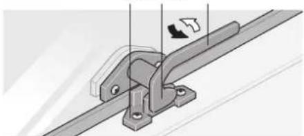
Mechanical assembly diagram showing a bracket with mounting holes and a directional arrow indicating motion (no text or symbols)Fig. 16 Opening and closing the hinged windows
1 Securing button
2 Lever
3 Latch plate
4 Fork
5 Locking catch
Opening the window:
→ If the locking lever has a securing button (Fig. 16/1), press and hold down the securing button.
→ Turn the lever (Fig. 16/2) to the middle of the window.
→ Open all window locks.
→ Open the window.
Closing the window:
→ Close the window.
→ If the locking lever has a securing button (Fig. 16/1), press and hold down the securing button.
→ Turn the lever (Fig. 16/2) to the window frame.
→ The fork (Fig. 16/4) of the lever (Fig. 16/2) closes completely on the inside of the latch plate (Fig. 16/3).
8.3.3 Permanent ventilation

Caution!
Cracks in the window
▲ Close only the levers (Fig. 15/2) at the bottom edge of the window in the "permanent ventilation" position, otherwise the window pane is bent. This could result in the formation of cracks in the acrylic glass window.
▲ Ensure all bottom catch bars are closed in the same position, otherwise, the window could be distorted.
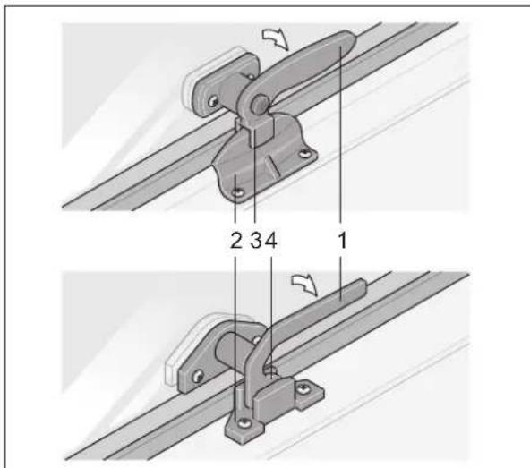
1 Lever
2 Latch plate
3 Fork
4 Locking catch
Fig. 17 Hinged window in permanent ventilation position
Setting the window to the "permanent ventilation" position
→ Open the locking levers as described in Chapter 8.3.2.
→ Pull the window back until it is almost closed.
→ With a locking lever (Fig. 17/1) with securing button, make sure the latch plate (Fig. 17/2) fits properly in the fork (Fig. 17/3) when closing the lever (Fig. 17/1).
With a locking lever (Fig. 17/1) without securing button, make sure the locking catch (Fig. 17/4) fits properly in the recess of the locking plate (Fig. 17/2) when closing the lever (Fig. 17/1).
8.3.4 Sliding windows (special equipment)
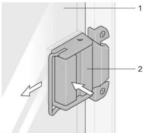
text_image
Technical diagram of a mechanical component with numbered parts and directional arrow indicating motion or forceFig. 18 Opening the sliding window
1 Window
2 Handle
Opening the sliding window:
→ Press the handle (Fig. 18/2).
→ Slide the window (Fig. 18/1) to the side.
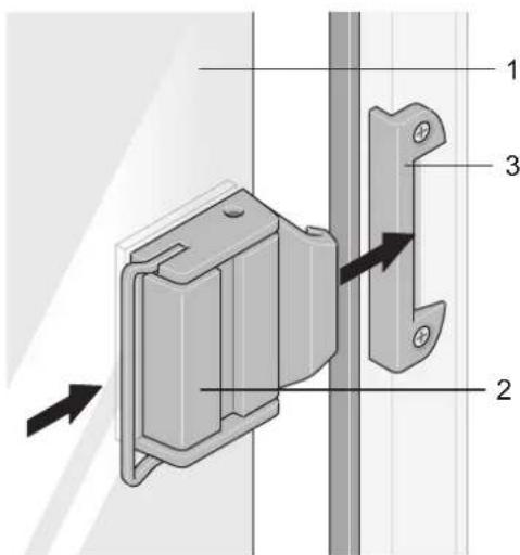
text_image
Technical diagram of a door lock mechanism with numbered components and directional arrows indicating movementFig. 19 Closing the sliding window
1 Window
2 Handle
3 Catch
Closing the sliding window:
→ Push the window (Fig. 19/1) until it is closed and the handle (Fig. 19/2) latches into place in the catch (Fig. 19/3).
8.4 Window blinds and insect screens
8.4.1 Blind and insect screen - version 1

Caution!
Damage to insect screen
When you unlock the blind/insect screen, hold on to the insect screen (Fig. 20/3), otherwise it will snap up with spring tension. Snapping up could damage the screen spring and the insect screen.
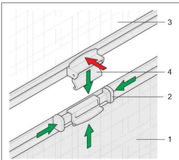
text_image
Technical diagram showing four labeled mechanical or electrical components with directional arrows indicating movement or flow.Fig. 20 Opening and closing of the blind and insect screen - version 1
1 Blind
2 Pushbuttons
3 Insect screen
4 Catch
The blind (Fig. 20/1) is located in the bottom part of the window frame.
The insect screen (Fig. 20/3) is installed in the top part of the window frame.
Opening and closing the blind:
→ Press the two pushbuttons (Fig. 20/2) together.
→ Slide the blind to the desired position.
Releasing the two pushbuttons automatically clamps the blind in place.
The blind (Fig. 20/1) has a restricting device so that it can be latched into place at different latching positions.
Opening and closing the insect screen:
→ Pull the insect screen (Fig. 20/3) down until the catch (Fig. 20/4) latches into place in the blind (Fig. 20/1).
The insect screen (Fig. 20/3) can be operated only in combination with the blind (Fig. 20/1).
Separating the insect screen from the blind:
→ Press on the upper catch (Fig. 20/4) of both blinds.
8.4.2 Blind and insect screen - version 2

Caution!
Damage to insect screen
When you unlock the blind (Fig. 21/1) and insect screen(Fig. 21/2), hold on to them, otherwise they will shoot up with spring tension. Shooting up could damage the screen spring and the blind/insect screen.
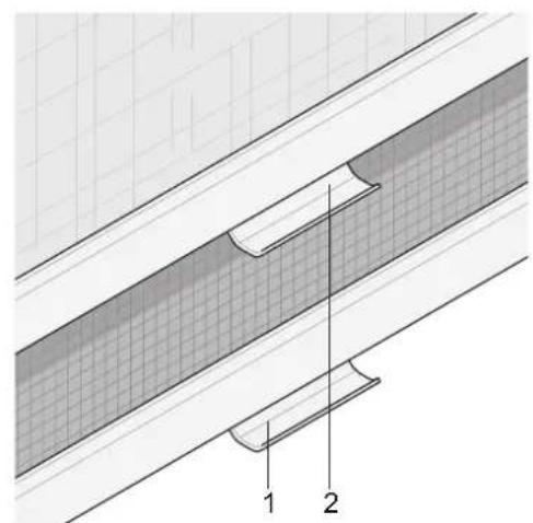
natural_image
Technical diagram of a structural joint or panel assembly with labeled components (1 and 2), showing layered materials and cross-sections without any readable text or symbols.Fig. 21 Opening and closing of the blind and insect screen - version 2
1 Insect screen with handle
2 Blind with handle
The blind (Fig. 21/1) and the insect screen (Fig. 21/2) are located in the upper part of the window frame and can be operated independently from each other.
Opening / closing the insect screen:
→ Pull down the insect screen (Fig. 21/1) by the handle and hook it on both sides of the window frame into the latches.
→ To unhook the insect screen from the latches, push the handle down and slightly pull it to the inside.
Opening / closing the blind:
To close the blind (Fig. 21/2), the insect screen (Fig. 21/1) must first be closed.
The blind (Fig. 21/2) has a restricting device so that it can be latched into place at different latching positions.
→ Pull down the blind (Fig. 21/2) by the handle. When the blind is closed completely, hook the blind into the latches on both sides of the window frame.
→ To unhook the blind from the latches, push the handle down and slightly pull it to the inside.
8.4.3 Blind and insect screen - version 3
The blind (Fig. 22/3) and the insect screen (Fig. 22/2) are both located in the upper window frame. The insect screen follows the blind.
| Fig. 22 Opening and closing of the blind and insect screen - version 3 | 1 Handle 2 Insect screen with handle 3 Blind 4 Handle bar |
Opening / closing the blind:
→ Pull the blind (Fig. 22/3) down or up with the grip bar (Fig. 22/4).
The blind (Fig. 22/1) can be moved up or down to any position.
Opening / closing the insect screen:
→ Pull the insect screen (Fig. 22/2) down or up with the handle (Fig. 22/1).
8.5 Roof openings
8.5.1 General
i Important!
- Before starting the journey, check the roof openings for damage to the glass dome.
- Close the roof openings when leaving the caravan. Danger of burglary or from rain water and wind.
- Do not open the roof openings when there is strong wind, rain or snowfall.
- Before opening the roof openings, remove snow, ice and other foreign material.
- Close the roof openings before starting the journey.
- Open the blind and insect screen before starting to drive.
- Consult an authorised workshop when faults or malfunctions occur.
8.5.2 Roof hood with operating bar (special equipment)
The roof hood with operating bar can be opened by tilting to one side.
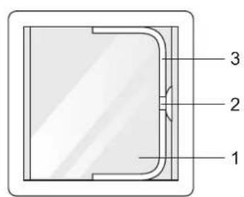
text_image
1 2 3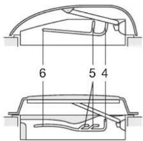
text_image
6 5 4Fig. 23 Opening / closing the roof hood with operating bar
1 Glass dome
2 Locking button
3 Bar
4 "Closed" position
5 "Ventilation" position
6 "Open" position
Opening the roof hood:
To open the glass dome (Fig. 23/1), press the locking button (Fig. 23/2) and pull the bar (Fig. 23/3) downwards.
→ Push the bar (Fig. 23/3) into the desired position. Possible positions are "Ventilation" (Fig. 23/5) or "Open" (Fig. 23/6).
Closing the roof hood:
→ Push the bar (Fig. 23/3) in the direction of the locking button (Fig. 23/2) to close the roof hood.
→ Press the locking button (Fig. 23/2) and push the bar (Fig. 23/3) into the "Closed" position.
8.5.3 Roof hood with crank operation (special equipment)
natural_image
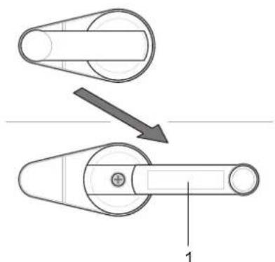
Mechanical diagram showing two pulley systems with a directional arrow indicating motion (no text or symbols)Fig. 24 Opening / closing the roof hood with crank operation
1 Hand crank
Opening the roof hood:
Some models are equipped with additional locking levers (Fig. 16).
To open the glass dome, you first have to fold out the hand crank (Fig. 24/1).
→ Turn the hand crank only until a resistance can be felt.
The roof hood is now in the maximum open position.
Any desired interim position is possible.
Closing the roof hood:
→ Turn the hand crank (Fig. 24/1) again until a resistance can be felt.
Before you fold in the hand crank again, a light initial tension must be present on the crank.
→ If required, loosen the attachment screw, take the crank out of the gearing and reposition the crank. Then place the crank onto the gearing again and screw tight.
Check the locking by attempting to lift the glass dome by hand.
→ Close the locking lever as required (Fig. 16).
8.5.4 Roof hood with rotary handle
Unlocking the roof hood:
→ Slide the catch bar (Fig. 25/2) of the roof hood to the "Unlock" position.
Locking the roof hood:
→ Slide the catch bar (Fig. 25/2) to the "Lock" position when the glass dome (Fig. 25/1) is closed.
natural_image
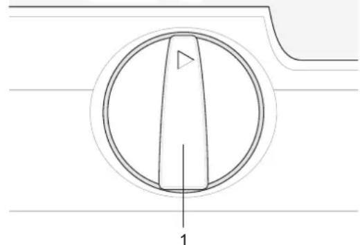
Technical diagram of a circular component with a triangular tip and labeled dimension '1' (no text or symbols beyond the label)Fig. 26 Opening / closing the roof hood
1 Rotary knob
Opening the roof hood:
→ Turn the rotary knob (Fig. 26/1) clockwise to open the glass dome.
→ Turn the rotary knob only until a resistance can be felt.
The roof hood is now in the maximum open position. Any desired interim position is possible.
Closing the roof hood:
→ Turn the rotary knob (Fig. 26/1) anticlockwise until a resistance can be felt.
→ Then lock the roof hood.
→ Check the locking by attempting to lift the glass dome by hand.
8.5.5 Roof hood blind and insect screen running in opposite directions
i Important!
- Both are continuously adjustable and can be operated together or separate from each other.
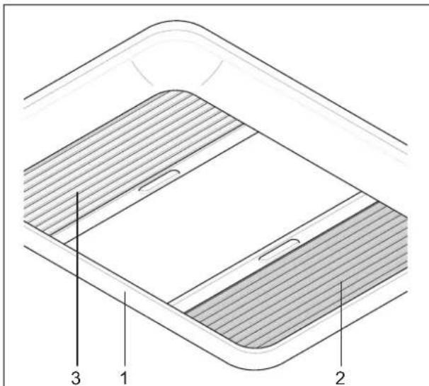
- Only close the blind to a maximum of 75% during direct sunlight. Air must be able to circulate.
text_image
Technical diagram of a device with labeled components 1, 2, and 3, showing layered structure and internal features.Fig. 27 Roof hood blind and insect screen running in opposite directions
1 Inner frame
2 Blind
3 Insect screen
The blind (Fig. 27/2) and the insect screen (Fig. 27/3) are fitted in the inner frame (Fig. 27/1) of the roof hoods.
Opening/closing the blind or insect screen:
Reach into the recess of the end bar of the blind (Fig. 27/2) or insect screen (Fig. 27/3).
→ Slide to the desired position.
8.5.6 Roof hood blind and insect screen running in the same direction

Important!
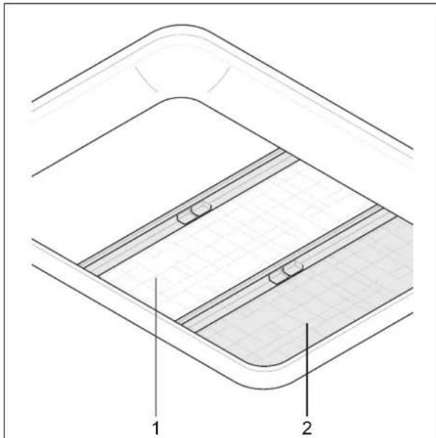
- Both are continuously adjustable and can be operated together or separate from each other.
• After releasing the grip, the blind is automatically clamped into place in the inner frame of the roof hood. - Only close the blind to a maximum of 75% during direct sunlight. Air must be able to circulate.
natural_image
Technical diagram of a mechanical component with labeled parts 1 and 2, showing internal layered structure (no text or symbols beyond labels)1 Insect screen
2 Blind
Fig. 28 Roof hood blind and insect screen running in the same direction
The blind (Fig. 28/2) and the insect screen (Fig. 28/1) are fitted in the inner frame of the roof hood.
Opening/closing the blind or insect screen:
→ Press the two halves of the grip of the blind (Fig. 28/2) or insect screen (Fig. 28/1) together.
→ Slide to the desired position.
8.5.7 Roof hood blind and insect screen running together
i Important!
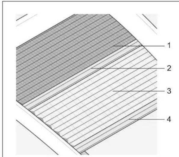
- Both folding screens are continuously adjustable and can be operated together or separate from each other.
• After releasing the operating bar, the folding screen remains in the position reached. - The insect screen is integrated into the second operating bar and allows maximum amount of light or darkening with insect screen function.
- Only close the folding blind to a maximum of 75% during direct sunlight. Air must be able to circulate.
text_image
1 2 3 4Fig. 29 Roof hood blind and insect screen running together
1 Insect screen
2 Operating bar of insect screen
3 Darkening
4 Operating bar of folding blind
Opening/closing the blind or insect screen:
The insect screen (Fig. 29/1) is firmly connected with the folding blind (Fig. 29/2). When the folding blind is opened, the insect screen may have to be moved as well.
→ Hold the folding blind (Fig. 29/3) on the operating bar (Fig. 29/4).
→ Slide to the desired position.
8.5.8 Care of roof hoods
For information on the care of the roof hoods, please see the "Care" Chapter (Chapter 19.1.1).
8.6 Control panel
Depending on the model, the following control panels have been installed in the caravans:
- LT 413 (with power supply unit CSV 4xx, Chapter 10.3.2)
• EN panel (with power supply unit BCA, Chapter 10.3.3)
Battery voltage and, depending on the model, water tank and fuel tank levels can be queried via the control panels.
The control panels are located indoors.
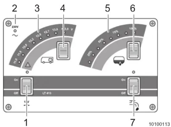
8.6.1 LT 413 control panel
text_image
2 3 4 5 6 23kV 11.0 11.8 12.0 12.2 12.6 12.7 13.0 13.5 V ~ 10% 75% 10% 25% On Off LT 413 Off 1 V 7 10100113Fig. 30 LT 413 control panel
1 "12 V On / Off" button
2 "External voltage supply 230 V" indicator
3 "Battery voltage" indicator
4 "Battery voltage" button
5 "Tank fill level" indicator
6 "Tank fill level" button
7 "Water supply" switch
"Onboard power supply 12 V" main switch:
→ Actuate the main switch of the onboard power supply (Fig. 30/1) to switch the supply voltage for all 12 V appliances on or off.
→ Switch off the main switch when you leave the caravan for a longer period of time.
i Important!
Refrigerator control is in operation even when the main switch is off.
"Battery voltage" button:
→ Push down the button (Fig. 30/4) to indicate the charged condition of the living area battery. Actuating the button at the top has no effect.
→ The "Battery voltage" (Fig. 30/3) indicator shows the charged condition of the living area battery.
"External voltage supply 230 V" indicator:
→ Connect the vehicle to a 230 V voltage supply (Chapter 10.1.1).
→ Make sure the circuit breaker in the fuse box (Chapter 10.2) is switched on.
The "External voltage supply 230 V 230 V" indicator (Fig. 30/2) is on.
"Tank level" button:
→ Push down the button (Fig. 30/6) to indicate the level of the water tank. Actuating the button at the top has no effect.
→ The "Tank fill level" Indicator (Fig. 30/5) shows how much water is in the water tank.
Switching the water supply on / off:
→ Press the "Water supply" switch (Fig. 30/7) to switch the supply voltage for the water pump on or off.
Opening a water tap switches the water pump on.
→ Switch off the water supply button when you leave the vehicle for a longer period of time.
For more information, see the separate instructions from the manufacturer.
8.6.2 Type EN Panel control panel
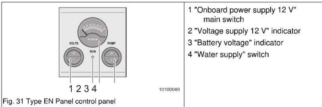
text_image
1 "Onboard power supply 12 V" main switch 2 "Voltage supply 12 V" indicator 3 "Battery voltage" indicator 4 "Water supply" switch Fig. 31 Type EN Panel control panel 10100049"Onboard power supply 12 V" main switch:
→ Actuate the main switch of the onboard power supply (Fig. 31/5) to switch the supply voltage for all 12 V appliances on or off.
When the 12 V onboard power supply is switched on, the control indicator (Fig. 31/2) lights, the current battery voltage is indicated on the "Battery voltage" indicator (Fig. 31/3).
→ Switch off the main switch when you leave the caravan for a longer period of time.
"Water supply" switch:
→ Actuate the "Water supply" switch (Fig. 31/5) to switch the supply voltage for the water pump on or off. Opening a water tap switches the water pump on.
→ Switch off the water supply button when you leave the vehicle for a longer period of time.
For more information, see the separate instructions from the manufacturer.
8.7 Central lighting control
Some vehicles have a central system for switching and dimming various lighting units. Channels 1 to 8 can be switched in series. Channel 9 is not normally served by the central switch but can be switched on and off using the Standby button of the central lighting control.
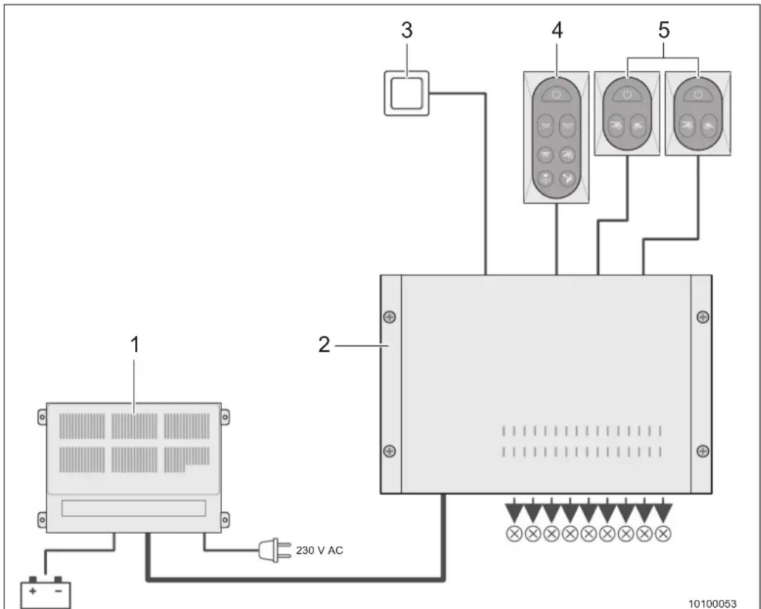
text_image
1 2 3 4 5 230 V AC 10100053Fig. 32 Central lighting control - Overview
1 12 V power supply unit
2 Lighting control device
3 Additional button with restricted functionality (option)
4 Central group for switching, controlling and programming (7 buttons)
5 Separate groups (max. 2 appliances) for switching and controlling (3 buttons)
A 12 V power supply unit is required to operate the system (Fig. 32/1).
Light assignment to channels is set at the factory and can only be modified by an ADRIA specialist dealer. Chapter 10.4 contains an example list based on ALPINA 763 UK.
i Important!
- The symbols shown and the associated configurations can vary from vehicle to vehicle. Your ADRIA specialist dealer will explain the configuration installed in your vehicle during handover.
- The dimming function cannot be used for certain channels depending on the lighting elements used.
- Use the Checklist in Chapter 21 should problems arise.
You can assign the channels to series 1 and 2 yourself.
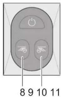
text_image
8 9 10 11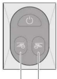
natural_image
Close-up of a gray electronic device control panel with three buttons and a power button (no text or symbols visible)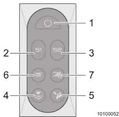
text_image
1 2 S1 S2 3 6 7 4 5 10100052Fig. 33 Central lighting control - switching units
1 Standby button with Coming Home function
2 Button, series 1 3 Button, series 2
4 Button, channel 1 5 Button, channel 2
6 Button, channel 3 7 Button, channel 4
8 Button, channel 5 9 Button, channel 6
10 Button, channel 7 11 Button, channel 8
| Function / channel | System is switched on System is switched off (Standby) | ||
| Press for about 1 second | Press longer Approx. 0.5 s | ||
| Channel 1 to 8 | Switch off. Press button about 1 second. Last dimming status is saved. | Dimming. Hold button pressed for about 1 second. Brightness is reduced at first and then increased or reduced every time pressed. | Switch on. Channel 9 also switches on. |
| Additional button. | Function as for channel 7. | Function as for channel 7. | Function as for channel 7. Channel 9 also switches on. |
| Series 1 Series 1 switches off. Hold button pressed for about 10 seconds. Program saves the channels switched on for series 1. | Series 1 switches on. Channel 9 also switches on. | ||
| Series 2 Series 2 switches off. Hold button pressed for about 10 seconds. Program saves the channels switched on for series 2. | Series 2 switches on. Channel 9 also switches on. | ||
| Standby button | All channels switch off including channel 9 (Standby). | Hold button pressed for about 10 seconds. Program saves the channels switched on for the "Coming Home" function. | All channels stored in the "Coming Home" function switch on. |
Tab. 3 Overview of central lighting control - channels
8.8 Seating group

Important!
The cushions must always be secured (also when parked) with all attachment devices.
Underneath the seat bench is the water tank (Chapter 12.1.1).
Servicing the water tank:
→ Remove the cushions.
→ Fold up the seat cushions to reach the service opening of the water tank.
8.9 Furniture locks

Caution!
Damage to the handles
▲ Do not pull too hard on a handle when the respective door, flap or drawer cannot be opened.
- First unlock the drawers before opening them.
- To close the bathroom door, always hold the door handle pressed fully down.
Depending on the production series, there can be different locking systems.
The drawings serve only to show the operating principle. Differences in form are possible.
8.9.1 Furniture locks - version 1

Caution!
Risk of damage through cupboard or drawer contents flying around!
▲ Carefully lock the cabinets and drawers before starting each journey.
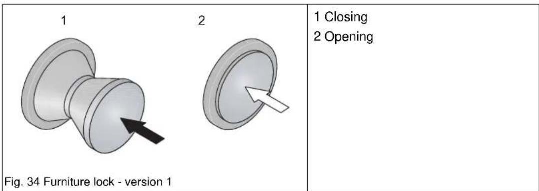
text_image
1 2 Fig. 34 Furniture lock - version 1 1 Closing 2 OpeningOpening:
→ Press the locking button (Fig. 34/1), the button springs out. The lock is unlocked.
→ Open the cabinet door, flap or drawer.
Closing:
→ Close the cabinet door, cabinet flap or drawer.
→ Push in the locking button until it latches into place (Fig. 34/2). The lock is locked.
8.9.2 Furniture locks - version 2
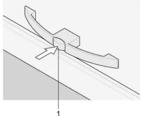
natural_image
Pure technical diagram of a mechanical component with no text or symbolsFig. 35 Furniture lock - version 2
1 Locking button
Opening:
→ Push the locking button, the button springs out. The lock is unlocked.
→ Open the cabinet door, flap or drawer.
Closing:
→ Close the cabinet door, cabinet flap or drawer.
→ Push in the locking button (Fig. 35/1) until it latches into place. The lock is locked.
8.9.3 Furniture locks - version 3
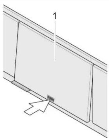
text_image
1 PINHFig. 36 Furniture lock - version 3
1 Flap
Opening:
→ Lightly press cabinet door, flap or drawer approximately in the middle. The pushing position is marked with "Push".
The lock is unlocked.
→ Open the cabinet door, flap or drawer.
Closing:
→ Close the cabinet door, flap or drawer.
→ Lightly press cabinet door, flap or drawer approximately in the middle. The pushing position is marked with "Push".
→ The cabinet door, flap or drawer is locked.
8.9.4 Furniture locks - bathroom
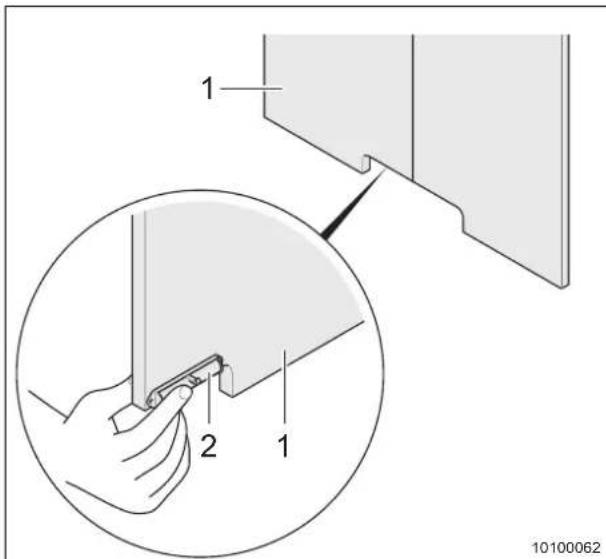
text_image
1 2 1 10100062Fig. 37 Furniture lock - bathroom
1 Cabinet door
2 Latch
Opening:
→ Put your fingers in the recess of the cabinet door (Fig. 37/1) and pull the latch (Fig. 37/2) on the rear.
The lock is unlocked.
→ Close the cabinet door (Fig. 37/1) and lightly press against the latch resistance until it clicks.
→ The cabinet door (Fig. 37/1) is locked.
8.10 Bathroom unit
8.10.1 Washbasin, foldable

Caution!
Damage to mirror and washbasin
▲ Always lower the washbasin slowly.
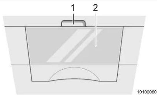
text_image
1 2 10100060Fig. 38 Washbasin, foldable - folded up
1 Grip hole
2 Washbasin (folded up)
Folding the washbasin down:
→ Grip inside the grip hole on the mirror (Fig. 38/1) and carefully pull the washbasin (Fig. 38/2) with mirror.
→ Fold the washbasin (Fig. 38/2) with mirror down.
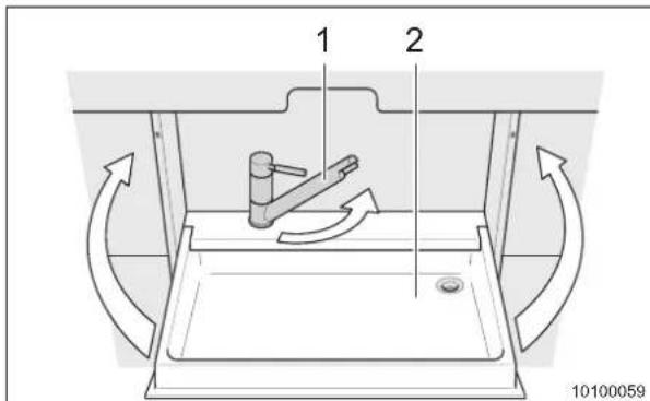
text_image
1 2 10100059Fig. 39 Washbasin, foldable - folded down
1 Water tap
2 Washbasin
Folding the washbasin up:
→ Turn the water tap (Fig. 39/1) to the rear until it almost touches the rear panel.
→ Fold the washbasin (Fig. 39/2) with mirror upwards and push it into the catch.
8.10.2 Folding shower door (special equipment) - version 1

Caution!
Damage to folding door or bathroom unit
▲ Secure the folding door (Fig. 40/1) with the lever (Fig. 40/2).
▲ If you leave the parking area with the caravan and the folding door is not secured, it can open and close uncontrolled during cornering.
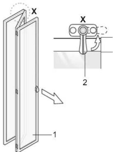
text_image
Technical diagram showing a door mechanism with labeled parts and directional arrows indicating movement or force.Fig. 40 Folding shower door - version 1
→ Unlock the lever (Fig. 40/2) before you close the folding door (Fig. 40/1).
Opening:
→ Push the folding door (Fig. 40/1) open.
→ Secure the door with the lever (Fig. 40/2).
8.10.3 Folding shower door (special equipment) - version 2

Caution!
Damage to folding door or bathroom unit
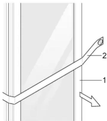
▲ Secure the folding door (Fig. 41/1) with the retaining strap (Fig. 41/2).
▲ If you leave the parking area with the caravan and the folding door is not secured, it can open and close uncontrolled during cornering.
text_image
Technical diagram showing a mechanical component with labeled parts 1 and 2, including an arrow indicating direction.Fig. 41 Folding shower door - version 2
1 Folding door
2 Retaining strap
Closing:
→ Loosen the retaining strap (Fig. 41/2) before you close the folding door (Fig. 41/1).
Opening:
→ Push the folding door (Fig. 41/1) open.
→ Secure the door with the retaining strap (Fig. 41/2).
8.11 TV equipment (special equipment)
Caution!
Damage to the vehicle
▲ Before starting the journey, you always have to lower and lock the antenna.
▲ Retract, lay it flat and secure the satellite dish before starting the journey.
▲ Lock the antenna mast into place to prevent twisting of the satellite dish.
Caution!
Damage to the cables
▲ Make sure the cables always have enough room to move.
Caution!
Damage to the appliance
▲ Check all locking grips are engaged before each journey.
▲ Check that all locking screws and locking brackets are screwed tight before each journey.
The caravan has been prepared for the installation of TV equipment: A location on the roof is intended for the installation of a satellite dish. Antenna cables and sockets have already been installed.
→ Check freedom of movement before the installation of an automatic antenna.
i Important!
- For more information concerning the installation of TV equipment, contact your ADRIA dealer.
- For more information, see the separate manufacturer's operating instructions.
8.11.1 TV slide-out and small parts shelf

Caution!
Damage to the cables
▲ Make sure the cables always have enough room to move.
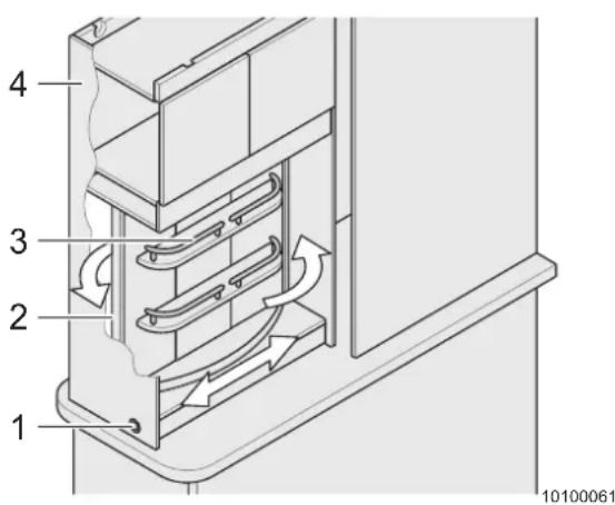
Some vehicles are fitted with a TV bracket combined with a small parts shelf. The TV (flat screen) can be fitted on the TV fixing surface (Fig. 42/2) on the rear side of the small parts shelf (Fig. 42/3). You can swivel the TV towards the sleeping or living area when in use.
text_image
1 2 3 4 10100061Fig. 42 TV bracket with small parts shelf
1 Locking button
2 TV fixing surface
3 Small parts shelf
4 TV slide-out
Sliding the TV out:
→ Unlock the locking button (Fig. 42/1) of the TV slide-out (Fig. 42/4) (Chapter 8.9).
→ Pull the TV slide-out (Fig. 42/4) towards the middle of the vehicle.
The TV is now ready for use. You can swivel the TV towards the sleeping or living area.
Slide the TV back in reverse sequence.
8.11.2 TV bracket with ceiling guide rail

Caution!
Damage to the cables
▲ Make sure the cables always have enough room to move.

Caution!
Damage to the appliance
▲ Check all locking grips are engaged before each journey.
▲ Check the locking screw is tightened before driving.
Some vehicles are fitted with a TV bracket with ceiling guide rail. The TV (flat screen) can be mounted on the fastening plate. You can swivel the TV towards the sleeping or living area when in use.

text_image
1 2 3 1010006-Fig. 43 TV bracket with ceiling guide rail
1 Locking screw
2 TV bracket
3 Cabinet door
Sliding the TV out:
→ Open the cabinet door(Fig. 43/3).
→ Loosen the locking screw (Fig. 43/1) anticlockwise until the TV bracket (Fig. 43/2) can be easily shifted.
→ Pull the TV bracket (Fig. 43/2) towards the middle of the vehicle.
The TV is now ready for use.
Slide the TV back in reverse sequence.
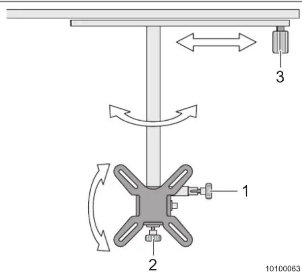
text_image
1 2 3 10100063Fig. 44 TV bracket with ceiling guide rail - adjustment option
1 Locking grip for turning
2 Locking grip for swivelling
3 Locking screw
Shifting the TV bracket:
→ Loosen the locking screw (Fig. 44/3).
→ Shift the TV bracket.
→ Tighten the locking screw (Fig. 44/3) by hand.
Turning or swivelling the TV bracket:
To adjust, pull the locking grip (Fig. 44/1) or (Fig. 44/2) and engage the locking grip again when finished.
For continuous freedom of movement, pull the locking grip (Fig. 44/1) or (Fig. 44/2) head of the locking grip and turn it 90°.
Fastening the TV bracket:
To engage the TV again, turn the knob of the locking grip (Fig. 44/1) or (Fig. 44/2) again until the cross pin locks into the groove.
Spring tension snaps the locking grip into the basic setting.
→ Turn the mounting plate until parallel to the guide rail.
The locking grip (Fig. 44/1) engages.
→ Swivel the mounting plate until vertical. The locking grip (Fig. 44/2) engages.
The locking grips secure the TV against movement.
8.11.3 TV bracket with wall mounting

Caution!
Damage to the cables
▲ Make sure the cables always have enough room to move.

Caution!
Damage to the appliance
▲ Check the TV bracket is secured with the locking bracket and locking screw before driving.
Some vehicles are fitted with a TV bracket with wall mounting. The TV (flat screen) can be mounted on the fastening plate. You can swivel the TV towards the sleeping or living area when in use.
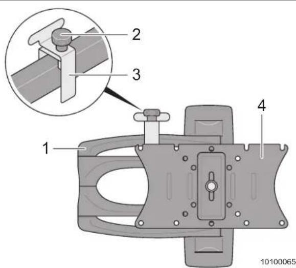
text_image
1 2 3 4 10100065Fig. 45 TV bracket with wall mounting
1 Joint
2 Locking screw
3 Locking bracket
4 Fastening plate
Loosening the TV:
→ Loosen the locking screw (Fig. 45/2) and turn it out completely.
→ Take the locking bracket (Fig. 45/3) off.
→ Swivel the joint (Fig. 45/1) out of the basic setting.
→ Attach the locking bracket (Fig. 45/3).
→ Turn in the locking screw (Fig. 45/2) and fasten by hand.
The TV is now ready for use.
Secure the TV in reverse sequence.
9 Sleeping arrangements
9.1 Beds
9.1.1 Fixed bed

Caution!
Risk of damage
▲ Lower the slatted frame slowly.
▲ Do not let it just drop down.
A bed storage compartment is under each bed. The bed storage compartment can be accessed either by swivelling the bed up or through an outside storage flap.
Swivel the slatted frame up to access the bed box.
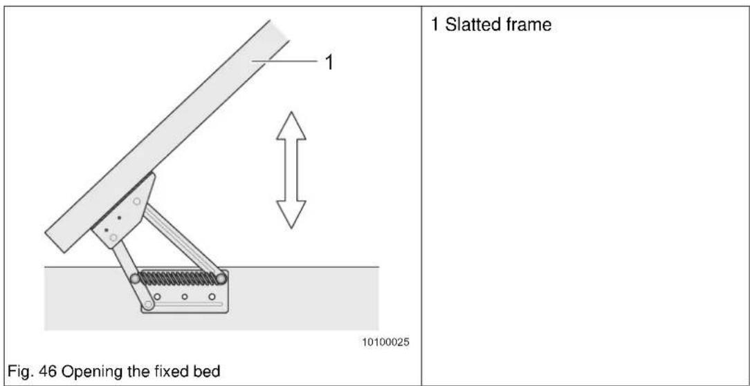
text_image
1 Slatted frame Fig. 46 Opening the fixed bed 10100025Opening the bed storage compartment:
→ Lift the slatted frame (Fig. 46/1). The slatted frame remains in the open position.
Closing the bed storage compartment:
→ Push the slatted frame downwards carefully and make sure it does not bang against the bed frame.
9.1.2 Bunk beds
Warning!
Accident hazard
▲ Do not use the bunk bed for storage of luggage during the journey.
▲ Place only the required bed linen on the bunk bed during the journey.
▲ Never allow small children to remain in the bunk bed without supervision.
▲ For children under 6 years of age, ensure they cannot fall out of the bunk bed.
▲ Use separate children's beds or travel cots suitable for small children.
▲ Always use the upper bunk bed with hung-in safety net.
▲ The maximum load of the bunk bed is 70 kg.
The caravans are equipped with bunk beds, depending on the model. The bunk beds can be used without conversion.
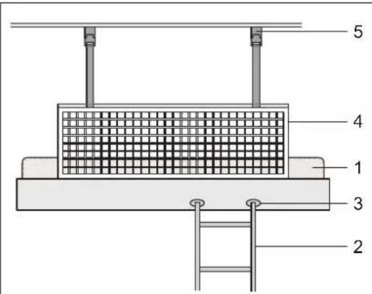
text_image
5 4 1 3 2Fig. 47 Bunk bed - guard against falling
1 Bunk bed (upper)
2 Ladder (special equipment)
3 Hook-in holes at the bunk bed (special equipment)
4 Guard against falling
5 Buckle latch guard against falling
→ Use the ladder (Fig. 47/2) to climb into the upper bunk bed (Fig. 47/1).
→ Hang the ladder (Fig. 47/2) into the hook-in holes provided (Fig. 47/3).
→ Close the guard against falling (Fig. 47/4) with the buckle latches (Fig. 47/5) in the vehicle ceiling when you are in the bed (Fig. 47/1).
9.1.3 Foldaway bed, wall unit (special equipment)

Warning!
Accident hazard
▲ Always open and close the foldaway bed with 2 persons.
▲ Always use the foldaway bed with hung-in safety net.
▲ Never allow children to remain in the foldaway bed without supervision. For children under 6 years of age, ensure they cannot fall out of the foldaway bed.
▲ Use separate children's beds or travel cots suitable for small children.
▲ The maximum load on the foldaway bed is 50 kg.
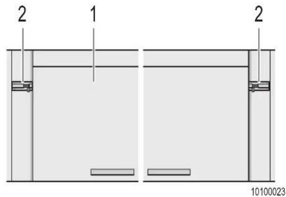
text_image
2 1 2 10100023Fig. 48 Opening the foldaway bed wall unit
1 Foldaway bed
2 Safety latch for foldaway bed
Opening the foldaway bed:
→ Empty the wall unit of the foldaway bed (Fig. 48/1).
→ Secure the wall unit with one hand and use the other hand to open the right and left safety latches (Fig. 48/2)..
→ Lower the wall unit slowly and fold out.
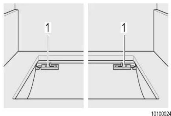
natural_image
Two identical line drawings of a floor planter with labeled components, no text or symbols present.Fig. 49 Safety latch for unit flaps
1 Safety latch for unit flaps
→ Secure the right and left unit flaps against unintentional opening with the safety latches (Fig. 49/1).
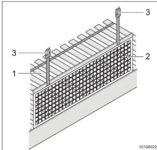
text_image
1 2 3 3 3 10100022Fig. 50 Opening the foldaway bed wall unit
1 Slatted frame
2 Guard against falling
3 Buckle latch of guard belts
→ Roll out the slatted frame (Fig. 50/1).
→ Lay the mattress on the frame (not shown).
→ Fix the guard against falling (Fig. 50/2) on the vehicle ceiling with the buckle latches (Fig. 50/3).
Closing the foldaway bed:
→ Close the foldaway bed wall unit in reverse sequence.
9.2 Lowering the table
9.2.1 Suspended table
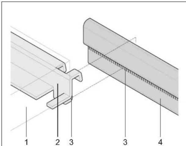
text_image
Technical diagram showing labeled components of a structural joint or panel assembly, with numbered parts 1 to 4.Fig. 51 Lowering the table
1 Table top
2 Table attachment rail
3 Attachment rail catch
4 Attachment rail wall
→ Slightly lift the table top (Fig. 51/1) by the free end (approx. 30°). This unlocks the catch (Fig. 51/3).
→ Lift the table top (Fig. 51/1) out of the upper attachment rail (Fig. 51/4).
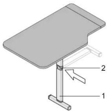
natural_image
3D diagram of a table with labeled parts (1, 2), showing structural components and an arrow indicating direction (no text or symbols beyond labels)Fig. 52 Swinging the table foot down
1 Table foot
2 Locking button
→ Press the locking button (Fig. 52/2) to unlock the table foot (Fig. 52/1).
→ Swing the table foot down 90°.
→ Then place the table in the bottom position against the seat.
9.2.2 Lowering the telescopic table
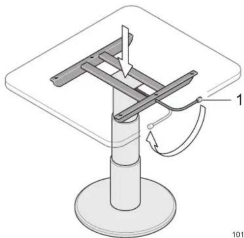
natural_image
Technical diagram of a mechanical assembly with a base and support structure, no visible text or symbolsFig. 53 Lowering the telescopic table
1 Locking lever
→ Hold the table top with one hand in the middle of the table
→ Turn the locking lever (Fig. 53/1) to the left with the other hand (unlocking).
→ Push the table top down to the lowest position.
→ Turn the locking lever (Fig. 53/1) to the right (locking).
9.2.3 Lowering the swivelling table
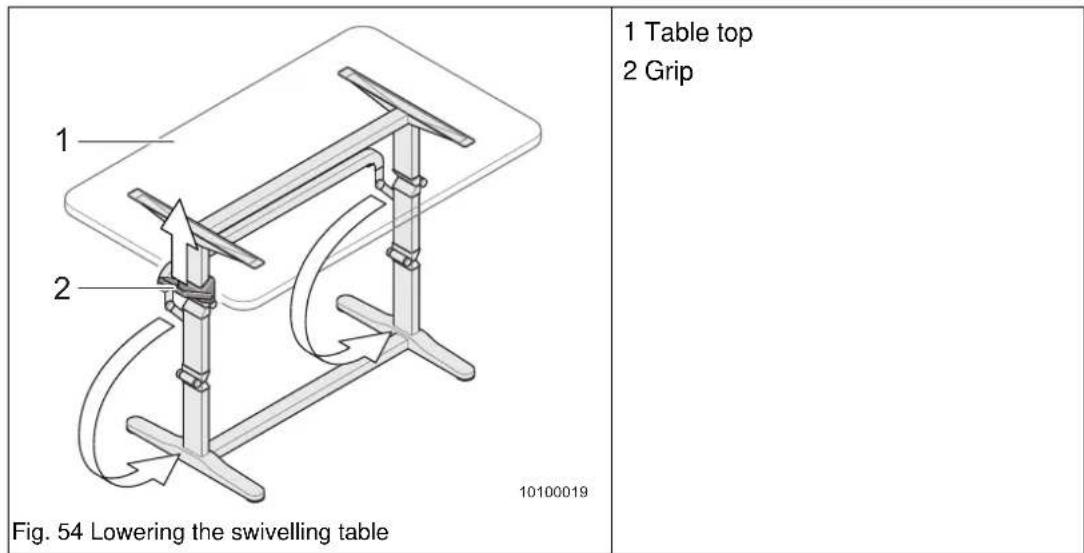
→ Push the grip (Fig. 54/2) upwards.
→ Swivel the table top (Fig. 54/1) downwards in an arch until the grip engages.
10 Power supply

Caution!
Short-circuit, corrosion and cable break
▲ For your own safety, have the electrical system checked at least once a year by an authorised workshop.
10.1 230 V power supply
The vehicle can be connected to an external power supply with 230 V which must be protected with a 30 mA ground-fault circuit breaker (fault current).
10.1.1 Making the electrical connection between the vehicle and the power source

Caution!
Danger of overheating of the cable on the cable reel
▲ Always unroll the cable completely from the cable reel. This prevents overheating of the cable.
▲ Use a cable reel with integrated overheat protection.

Important!
- Connectors and sockets do not fit in every country.
- It is possible that an adapter set is required for the country being visited.
The connection of the vehicle to the external 230 V power supply must be made with a rubber sheathed cable "H0 RN-F 3G 2.5 mm ^2 " or an equivalent cable with connectors according to "IEC 309". The overall length of the electric cable should not exceed 25 m!
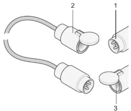
natural_image
Diagram of a cable connector with three labeled parts (1, 2, 3), showing different connection configurations (no text or symbols beyond labels)Fig. 55 230 V mains connection
1 CEE motorcar input socket
2 CEE extension cable (special accessory) with a minimum cross-section: 2.5 mm ^4
3 Power source
Connecting:
→ When making the connection, always begin on the vehicle and make the connection to the power source last.
Disconnect in reverse sequence.
10.2 Fuse protection of the 230 V electric circuit in the vehicle
The external 230 V power supply of the vehicle is protected with a 13 A circuit breaker. In addition to the circuit breakers, a ground-fault circuit breaker (special equipment) is installed in some vehicles.
The ground-fault circuit breaker protects persons against electric shock if the insulation of electrical appliances is defective.
i Important!
Check the ground-fault circuit breaker for fault-free operation monthly or, after a longer period of standstill of the vehicle, before starting each journey.
The fuse box with circuit breakers and ground-fault circuit breaker is normally installed in the wardrobe or a seat chest.
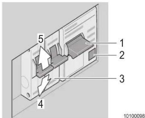
text_image
1 2 3 4 5 10100098Fig. 56 230 V circuit breaker
1 Ground-fault circuit breaker
2 "Test" button of ground-fault circuit breaker
3 Circuit breakers
4 "Off" position
5 "On" position
Checking the ground-fault circuit breaker:
→ Press the "Test" button (Fig. 56/2) of the ground-fault circuit breaker with the 230 V power supply connected.
The ground-fault circuit breaker (Fig. 56/1) triggers, the switch handle springs to the "Off" position.
→ Switch the handle of the ground-fault circuit breaker back to the "On" position after the successful test.
Switching on the circuit breaker:
To switch on the circuit breaker (Fig. 56/3), push the switch handle upward.
When the circuit breaker has triggered, wait for a short time before switching on again.
- If the circuit breaker remains on, only an overload occurred.
- If the circuit breaker immediately triggers again, this is due to a short-circuit or earth fault. Consult an authorised workshop and have the fault repaired.
i Important!
It makes no sense to switch the breaker on several times. The circuit breaker triggers even when you hold the switch handle.
10.3 12 V power supply
10.3.1 Power supply unit CSV 300-X

Warning!
Risk of burns
▲ The power supply unit becomes hot when in use. Do not touch.
▲ Replace defective fuses only when the power supply unit has been de-energised.

Caution!
Damage to power supply unit
▲ Replace defective fuses only when the power supply unit has been de-energised.
▲ Replace defective fuses only when the cause of the defect is known and has been remedied.
▲ Never bridge or repair fuses.
▲ Use only original fuses with the values specified in the operating instructions.
▲ Do not lay any cables underneath the power supply unit due to the heat generation.
The power supply unit is designed for use in caravans without own living area battery and therefore cannot be used to charge batteries.
Connected appliances can be supplied with 12 V current from the towing vehicle when the 230 V mains voltage is not available.
Mains operation is switched to automatically as soon as the 230 V mains voltage is available.
The power supply unit comprises:
• The power supply module
• The complete 12 V distribution
• The fuse protection for the 12 V electric circuit
The following 12 V outputs are supplied with power when the power supply unit is fed 12 V from the starter battery of the towing vehicle without the 230 V mains being connected:
- CSV 300 circuits 1 to 5 receive power
- CSV 300-2 circuit 1 receives power, circuits 2 to 5 do not receive power
- CSV 300-3 circuits 1 to 4 receive power, circuit 5 does not receive power
Permanent power supply to all electric circuits is possible when operating with a towing vehicle. Refer to the separate operating instructions for information in this context.
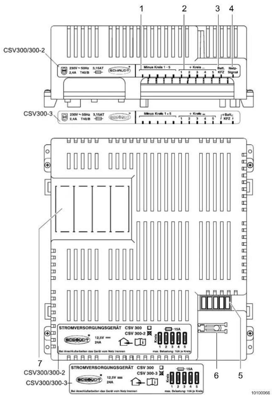
Fig. 57 Power supply unit CSV 300-X
1 Minus 12 V output, circuits 1 to 5
2 + 12 V output, circuits 1 to 5
3 Car battery/towing bracket
4 Mains signal (only for CSV 300-2), car battery (only for CSV 300-3)
5 Vehicle flat blade fuses
6 FK-puller (tool to remove fuses)
7 Space for circuit breakers
Placing into service:
→ The system is ready for operation when the 12 V supply from the towing vehicle or the 230 V mains voltage is connected. The unit does not have to be switched on separately.
Vehicle flat blade fuses
The vehicle flat blade fuses (Fig. 57/3) protect the various electric circuits.
A tool to exchange the vehicle flat blade fuses (FK-puller) is fitted next to the vehicle flat blade fuses.
For more information, see the separate instructions from the manufacturer.
10.3.2 Power supply unit CSV 4xx
The power supply unit is normally fitted in a cabinet or storage space and can be accessed to exchange fuses. Depending on the vehicle equipment, different voltage supply units of the 4xx series are used (xx stands for the different versions of the appliance). For the exact type of the power supply units used in your vehicle, check the nameplate on the appliance and the separate instructions from the manufacturer.

Danger!
Risk of explosion caused by formation of detonating gas
▲ Set the battery selector switch (Fig. 58/6, not CSV 400) to the correct position.

Warning!
Risk of burns
▲ The power supply unit becomes hot when in use. Do not touch.
▲ Replace defective fuses only when the power supply unit has been de-energised.

Caution!
Damage to power supply unit
▲ Replace defective fuses only when the power supply unit has been de-energised.
▲ Replace defective fuses only when the cause of the defect is known and has been remedied.
▲ Never bridge or repair fuses.
▲ Use only original fuses with the values specified in the operating instructions.
▲ Do not lay any cables underneath the power supply unit due to the heat generation.
▲ Do not store any heat sensitive objects near the unit (e.g. temperature sensitive clothing when the unit is fitted in the wardrobe).

Important!
- The power supply unit can only be operated together with the control panel.
-
The following prerequisites must be fulfilled for 12-V operation of the refrigerator (all other 12-V appliances are switched off):
-
The caravan is connected to the towing vehicle
- The ignition of the towing vehicle is switched on
The caravan battery (special accessory) or the towing vehicle battery can provide power for connected devices when no mains connection is available. Mains operation is switched to automatically as soon as the 230 V mains voltage is available.
The power supply unit CSV 4xx contains:
• The complete 12 V distribution
• The fuse protection for the 12 V electric circuit
- A charging module to charge all connected batteries (not CSV 400)
• A battery booster (not CSV 400)
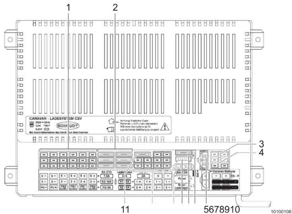
1 Connections for 12 V consumers
2 Vehicle flat blade fuses for 12 V electric circuits
3 Connections for 12 V consumers
4 12 V supply, towing vehicle
5 Caravan battery connection (not CSV 400)
6 Battery selector switch (not CSV 400)
7 Solar flat blade fuse (not CSV 400)
8 Connection for control panel
9 Connection for solar charge regulator (not CSV 400)
10 Connections for 12 V consumers
11 Vehicle flat blade fuses for refrigerator control (not CSV 400)
Before placing into service (not CSV 400):
→ Check whether the battery selector switch (Fig. 58/6) is in the correct position.
→ Make sure the living area battery is connected.
Placing into service:
The 12 V main switch on the control panel serves to switch the system on (Chapter 8.6).
Vehicle flat blade fuses
The vehicle flat blade fuses (Fig. 58/2) protect the various power circuits
Battery selector switch (not CSV 400)
If the battery selector switch (Fig. 58/6) is set to the wrong position, the living area battery could become damaged.
Switching the battery selector switch (not CSV 400):
→ Disconnect the power supply unit from the mains before setting the battery selector switch (Fig. 58/6) to a different position.
→ Selection of lead-gel battery: Set the battery selector switch to "Gel".
→ Selection of lead-acid battery: Set the battery selector switch to "Acid".
Use a thin object for the changeover (e.g. ball-point pen refill).
The option of switching over with the battery selector switch ensures optimum charging of the two battery types (lead-gel or lead-acid).
For more information, see the separate instructions from the manufacturer.
10.3.3 Power supply unit type BCA

Warning!
Risk of burns
▲ The power supply unit becomes hot when in use. Do not touch.
▲ Replace defective fuses only when the power supply unit has been de-energised.

Caution!
Damage to power supply unit
▲ Replace defective fuses only when the power supply unit has been de-energised.
▲ Replace defective fuses only when the cause of the defect is known and has been remedied.
▲ Never bridge or repair fuses.
▲ Use only original fuses with the values specified in the operating instructions.
▲ Do not lay any cables underneath the power supply unit due to the heat generation.
▲ Do not store any heat sensitive objects near the unit (e.g. temperature sensitive clothing when the unit is fitted in the wardrobe).

Important!
The power supply unit may be operated only together with the control panel.
The power supply unit is the central power supply unit for all 12 V consumers in the electrical system in the caravan. It is normally fitted in a cabinet or storage space and can be accessed from the front to exchange fuses.
The caravan battery or the towing vehicle battery can provide power for connected devices when no mains connection is available. Mains operation is switched to automatically as soon as the 230 V mains voltage is available.
The power supply unit BCA comprises:
- A charging module to charge all connected batteries
• The complete 12 V distribution
• The fuse protection for the 12 V electric circuit
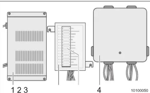
text_image
1 2 3 4 10100050Fig. 59 Power supply unit BCA
1 Charging module to charge all connected batteries
2 12 V distribution
3 Vehicle flat blade fuses for 12 V electric circuits
4 Junction box for 12 V electric circuits
Before placing into service:
→ Make sure the living area battery is connected.
Placing into service:
→ The 12 V main switch on the control panel serves to switch the system on (Chapter 8.6.2).
Vehicle flat blade fuses
The vehicle flat blade fuses (Fig. 59/3) protect the various power circuits
For more information, see the separate instructions from the manufacturer.
10.3.4 Starter battery (in towing vehicle)

Caution!
Discharging of starter battery
▲ The capacity of the starter battery is limited.
▲ The starting capability of the towing vehicle is affected when the power supply is provided for an extended period of time via the constant plus of the towing vehicle.
If the vehicle is externally connected to the 230 V power source (Chapter 10.1.1), an automatic changeover from 12 V to 230 V / 12 V (power supply unit) occurs.
10.3.5 Living area battery (special accessory)

Warning!
Deflagration
▲ The use of acid batteries as living area batteries in the caravan is not allowed. The installation area is not equipped for accommodation of an acid battery.
Only gel or AGM batteries may be used as living area battery.
The living area battery can be charged in two ways:
- With the towing vehicle generator, i.e. while the engine is running. All major appliances such as refrigerator, heater, water pump, etc. must be switched off. The battery should then be "fully" charged at the 230 V mains.
- By connection to the 230 V mains. This charges the battery automatically. All major appliances must be switched off.
Regularly check the battery voltage with the control panel (Chapter 8.6):
- If the voltage is 12 V or higher or in the green area, everything is okay. - If the voltage is less than 12 V or in the red area, switch off all appliances immediately and charge the battery. The minimum charging time should be 24 hours or better 48 hours. Overcharging is automatically prevented by the battery charger.
- If the "Battery alarm" warning light blinks, the battery must be charged immediately for a minimum of 48 hours with the built-in automatic battery charger or a separate charger. For this purpose, the vehicle must be connected to the 230V power supply. If the battery voltage has dropped below 3V , the engine must be started for approx. 10 seconds so that the battery charger is switched on. Then charge the battery for a minimum of 48 hours.

Important!
- Before and after each use of the vehicle, the battery should be charged with the battery charger, if possible, for more than 24 hours.
- If you are on the way for a longer journey, the battery should be "fully" charged at least once a month via the 230 V mains.
- If the vehicle is not used for a longer period of time, all appliances must be switched off (pay attention to hidden appliances, for example satellite system, tank heating, boiler safety valve, etc.). The easiest way to do this is to disconnect the plus pole directly on the battery. Charge the battery once a month with the built-in battery charger or a minimum of 24 hours.
- The warranty for the auxiliary battery is valid only when it is serviced properly.
10.3.6 Control panel
For more information on the control panels, see Chapter 8.6.
10.4 Central lighting control - light assignment
Light assignment to channels of the central lighting control is set at the factory and can only be modified by an ADRIA specialist dealer.
An example Table for the ALPINA 763 UK serves as overview:
| Channel Light |
| 1 • Ceiling lights, dining table |
| 2 • Awning light |
| 3 • Decorative lighting, circular seating group |
| 4 • Indirect lighting, circular seating group |
| 5 • Indirect lighting, double bed |
| 6 • Ceiling lights, double bed |
| 7 • Ceiling lights, children's room• Decorative lighting, children's room |
| 8 • Ceiling lights, children's room |
| 9 • Washroom lighting• Toilet compartment lighting• Reading lights, children's room• Reading lights, double bed• Storage space lighting• Reading lights, circular seating group |
Tab. 4 Central lighting control, channel assignment ALPINA 763 UK
10.5 Fuses

Warning!
Risk of burns
▲ Replace defective fuses only when the power supply unit has been de-energised.

Caution!
Damage to the electrical system
▲ Replace defective fuses only when the cause of the defect is known and has been remedied.
▲ Never bridge or repair fuses.
▲ Use only original fuses with the same rating.
Fuses protect the electrical system and the electrical appliances from damage by overloading and short circuits. If the amperage is too high, a fuse automatically interrupts the electric circuit.
The electric fuses are accessible at different installation locations in the vehicle.
The appliances that are connected to the 12 V supply in the living area are protected by their own fuses.
Before changing fuses, see the following table for function, value and colour of the respective fuses:
| Amperage Colour Function Installation location | |||
| 2 A Grey Fuse | of living area | battery In the 12 V power supply | unitor next to the living area bat-tery |
| 3 A Violet Fuses | of Thetford | toilet In the housing frame of the | Thetford cassette or in the12 V power supply unit |
| 20 A Yellow Fuse | use of refrigerator | In the 12 V power supply unit | |
| 50 A Red | Fuse of 1 | 2 V power supplyunit | Next to the living area battery |
Tab. 5 Fuses
Changing the fuses:
→ A fuse must be changed when the fuse element is interrupted (Fig. 60/2).
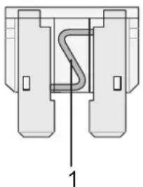
natural_image
Pure mechanical component diagram without any text, numbers, or symbols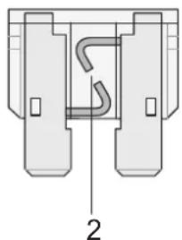
natural_image
Pure mechanical component diagram without any text, numbers, or symbolsFig. 60 12 V fuse
1 Intact fuse element
2 Interrupted fuse element
10.6 Electrical diagrams 230 V

Caution!
Damage to the electrical system
▲ Have maintenance and repair work performed by an authorised workshop.
▲ Improper maintenance and repair work voids your warranty claims.
See the following electrical diagrams for the exact layout of the electrical components and wiring.
These diagrams are required for possible repairs and maintenance.
| A Power input 220-240 V, 16 A, 2P+T | |
| B Main fuse with FI 220-240 V, 25 A, 0.03A | |
| B1 Circuit breaker 220-240 V, B16A | |
| B2 Circuit breaker 220-240 V, C10A | |
| B3 Circuit breaker 220-240 V, C10A or B16A | |
| C Junction box | |
| D Socket with earth contact 220-240 V | |
| E Refrigerator | |
| F | Protective earthing (H07V-K) 4mm^2 |
| G Heater/boiler | |
| H Boiler switch (TRUMA THERME) | |
| I Air-conditioner, pre-installation (roof top) | |
| /// 3-wire cable (H05VV-F) | |
Tab. 6 Legend for the following electrical diagrams for 230 V installation
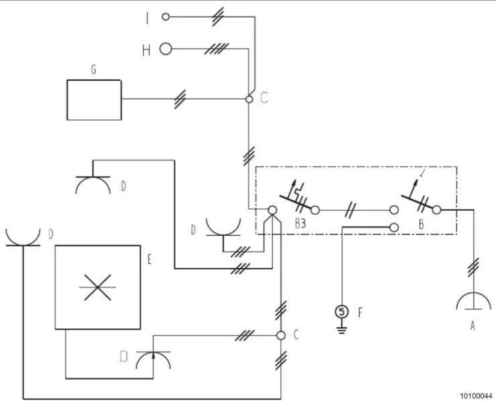
text_image
I H G C D D E B3 B 5 F A 10100044Fig. 61 Electrical diagram 230 V: AVIVA-ALTEA-ACTION-ADORA
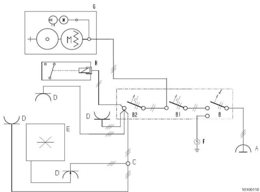
text_image
G M + - H D D B2 B1 B F A 10100110 E C DFig. 62 Electrical diagram 230 V: ASTELLA-ALPINA
10.7 Electrical diagrams for 12 V supply from towing vehicle
| No. Function Type | ||
| A1 Brake light and rear light PY21/5W | ||
| A2 Reversing light P21W | ||
| A3 Rear fog light P21W | ||
| A4 Direction indicator PY21W | ||
| B1/B2 License plate light C5W | ||
| E Contour light, red/white W5W | ||
| E1 Side marker light - orange LED | ||
| F1/F2 | Contour light, front - white | LED |
| M | 3rd brake light | LED |
| N | Earth connection | |
| O | Caravan charging station, power supply unit | |
| U | Connector plug for towing vehicle | |
Tab. 7 Legend, function of 12 V towing vehicle supply
| No. Colour | No. Colour | |||
| 01 | Black | 19 | Blue - white stripe | |
| 02 | Red | 21 | White - blue stripe | |
| 03 | Green 23 | Green - red stripe | ||
| 04 | Blue | 24 | Lilac - white stripe | |
| 05 | White | 25 | Orange - black stripe | |
| 06 | Brown | 26 | Green - blue stripe | |
| 07 | Yellow | 27 | White - black stripe | |
| 08 | Lilac | 28 | White - red stripe | |
| 09 | Grey | |||
| 12 | Pink | |||
| 13 | Orange | |||
Tab. 8 Legend, colours of 12 V towing vehicle supply
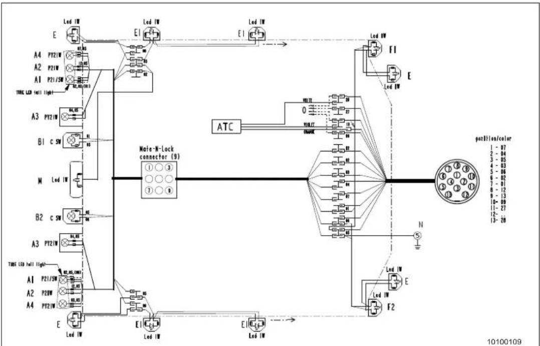
flowchart
graph TD
    A["LED I/W"] --> B["E1"]
    B --> C["LED I/W"]
    C --> D["E1"]
    D --> E["LED I/W"]
    E --> F["LED I/W"]
    F --> G["E1"]
    G --> H["LED I/W"]
    H --> I["LED I/W"]
    I --> J["ATC"]
    J --> K["MTA-N-Lock connector (9)"]
    K --> L["Pin ①②③④⑤⑥⑦⑧⑨⑪⑫"]
    L --> M["Pin ①②③④⑤⑥⑦⑧⑨⑩⑪⑫"]
    M --> N["Pin ①②③④⑤⑥⑦⑧⑨⑩⑪⑫"]
    N --> O["Pin ①②③④⑤⑥⑦⑧⑨⑩⑪⑫"]
    O --> P["Pin ①②③④⑤⑥⑦⑧⑨⑩⑪⑫"]
    P --> Q["Pin ①②③④⑤⑥⑦⑧⑨⑩⑪⑫"]
    Q --> R["Pin ①②③④⑤⑥⑦⑧⑨⑩⑪⑫"]
    R --> S["Pin ①②③④⑤⑥⑦⑧⑨⑩⑪⑫"]
    S --> T["Pin ①②③④⑤⑥⑦⑧⑨⑩⑪⑫"]
    T --> U["Pin ①②③④⑤⑥⑦⑧⑨⑩⑪⑫"]
    U --> V["Pin ①②③④⑤⑥⑦⑧⑨⑩⑪⑫"]
    V --> W["Pin ①#100109"]
    style A fill:#f9f,stroke:#333
    style B fill:#ccf,stroke:#333
    style C fill:#cfc,stroke:#333
    style D fill:#fcc,stroke:#333
    style E fill:#cff,stroke:#333
    style F fill:#ffc,stroke:#333
    style G fill:#cfc,stroke:#333
    style H fill:#cfc,stroke:#333
    style I fill:#cfc,stroke:#333
    style J fill:#cfc,stroke:#333
    style K fill:#cfc,stroke:#333
    style L fill:#cfc,stroke:#333
    style M fill:#cfc,stroke:#333
    style N fill:#cfc,stroke:#333
    style O fill:#cfc,stroke:#333
    style P fill:#cfc,stroke:#333
    style Q fill:#cfc,stroke:#333
    style R fill:#cfc,stroke:#333
    style S fill:#cfc,stroke:#333
    style T fill:#cfc,stroke:#333
    style U fill:#cfc,stroke:#333
    style V fill:#cfc,stroke:#333
    style W fill:#cfc,stroke:#333
    style X fill:#cfc,stroke:#333
    style Y fill:#cfc,stroke:#333
    style Z fill:#cfc,stroke:#333
Fig. 63 Electrical diagram 12 V: ASTELLA-ALPINA
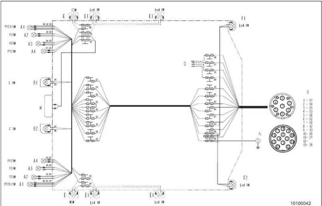
flowchart
graph TD
    A["Pin 1: P21/5M"] --> B["Pin 2: P21W"]
    B --> C["Pin 3: P21W"]
    C --> D["Pin 4: P21W"]
    D --> E["Pin 5: P21W"]
    E --> F["Pin 6: P21W"]
    F --> G["Pin 7: P21W"]
    G --> H["Pin 8: P21W"]
    H --> I["Pin 9: P21W"]
    I --> J["Pin 10: P21W"]
    J --> K["Pin 11: P21W"]
    K --> L["Pin 12: P21W"]
    L --> M["Pin 13: P21W"]
    M --> N["Pin 14: P21W"]
    N --> O["Pin 15: P21W"]
    O --> P["Pin 16: P21W"]
    P --> Q["Pin 17: P21W"]
    Q --> R["Pin 18: P21W"]
    R --> S["Pin 19: P21W"]
    S --> T["Pin 20: P21W"]
    T --> U["Pin 21: P21W"]
    U --> V["Pin 22: P21W"]
    V --> W["Pin 23: P21W"]
    W --> X["Pin 24: P21W"]
    X --> Y["Pin 25: P21W"]
    Y --> Z["Pin 26: P21W"]
    Z --> AA["Pin 27: P21W"]
    AA --> AB["Pin 28: P21W"]
    AB --> AC["Pin 29: P21W"]
    AC --> AD["Pin 30: P21W"]
    AD --> AE["Pin 31: P21W"]
    AE --> AF["Pin 32: P21W"]
    AF --> AG["Pin 33: P21W"]
    AG --> AH["Pin 34: P21W"]
    AH --> AI["Pin 35: P21W"]
    AI --> AJ["Pin 36: P21W"]
    AJ --> AK["Pin 37: P21W"]
    AK --> AL["Pin 38: P21W"]
    AL --> AM["Pin 39: P21W"]
    AM --> AN["Pin 40: P21W"]
    AN --> AO["Pin 41: P21W"]
    AO --> AP["Pin 42: P21W"]
    AP --> AQ["Pin 43: P21W"]
    AQ --> AR["Pin 44: P21W"]
    AR --> AS["Pin 45: P21W"]
    AS --> AT["Pin 46: P21W"]
    AT --> AU["Pin 47: P21W"]
    AU --> AV["Pin 48: P21W"]
    AV --> AW["Pin 49: P21W"]
    AW --> AX["Pin 50: P21W"]
    AX --> AY["Pin 51: P21W"]
    AY --> AZ["Pin 52: P21W"]
    AZ --> BA["Pin 53: P21W"]
    BA --> BB["Pin 54: P21W"]
    BB --> BC["Pin 55: P21W"]
    BC --> BD["Pin 56: P21W"]
    BD --> BE["Pin 57: P21W"]
    BE --> BF["Pin 58: P21W"]
    BF --> BG["Pin 59: P21W"]
    BG --> BH["Pin 60: P21W"]
    BH --> BI["Pin 61: P21W"]
    BI --> BJ["Pin 62: P21W"]
    BJ --> BK["Pin 63: P21W"]
    BK --> BL["Pin 64: P21W"]
    BL --> BM["Pin 65: P21W"]
    BM --> BN["Pin 66: P21W"]
    BN --> BO["Pin 67: P21W"]
    BO --> BP["Pin 68: P21W"]
    BP --> BQ["Pin 69: P21W"]
    BQ --> BR["Pin 70: P21W"]
    BR --> BS["Pin 71: P21W"]
    BS --> BT["Pin 72: P21W"]
    BT --> BU["Pin 73: P21W"]
    BU --> BV["Pin 74: P21W"]
    BV --> BW["Pin 75: P21W"]
    BW --> BX["Pin 76: P21W"]
    BX --> BY["Pin 77: P21W"]
    BY --> BZ["Pin 78: P21W"]
    BZ --> CA["Pin 79: P21W"]
    CA --> CB["Pin 80: P21W"]
Fig. 64 Electrical diagram 12 V: AVIVA-ALTEA-ACTION-ADORA
10.8 Electrical diagrams, voltage supply
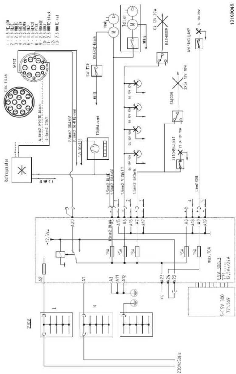
text_image
1-1.5 YELLOW 2-1.5 BLUE 3-2.5 WHITE 4-1.5 GREEN 5-1.5 BROWN 6-1.5 RED 7-1.5 BLACK 8-1.5 PINK 9-2.5 ORANGE 10-2.5 GRAY 11-2.5 WHITE-BLCK 12-2.5 WHITE-red WEST DUN TRADE 2.5mm2 ORANGE 2.5mm2 WHITE-red TOMA-VRW SWITCH ORANGE-BLCK MΩ MΩ MΩ MΩ MΩ MΩ MΩ MΩ MΩ MΩ MΩ MΩ MΩ MΩ MΩ MΩ MΩ MΩ MΩ MΩ MΩ MΩ MΩ MΩ MΩ MΩ MΩ MΩ MΩ MΩ MΩ MΩ MΩ MΩFig. 65 Electrical diagram 12 V appliances: AVIVA-ALTEA
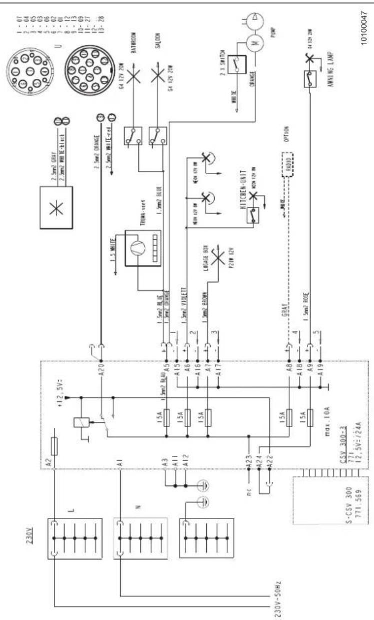
text_image
1 - 07 2 - 04 3 - 05 4 - 03 5 - 06 6 - 02 7 - 01 8 - 12 9 - 13 10 - 09 11 - 27 12 - 28 U BATHROOM SALOON G4 12V ZON GA 12V ZON 2.3mm2 ORANGE 2.5mm2 WHITE/gray TRIMM-vert 1.5mm2 BLUE 1.5mm2 VOLTLETT 1.5mm2 GREEN LARGE BOD PZW 12V KITCHEN-UNIT ORANGE 2.3 SWITCH WHITE PUMP 04 12V ZIN AMNI NG LAMP 10100047 A20 +12.5V~ A1 A3 A11 A12 A23 A24 A22 nc CSV 300-3 771 12.5V/24A L N 230V-50HzFig. 66 Electrical diagram 12 V appliances: ACTION
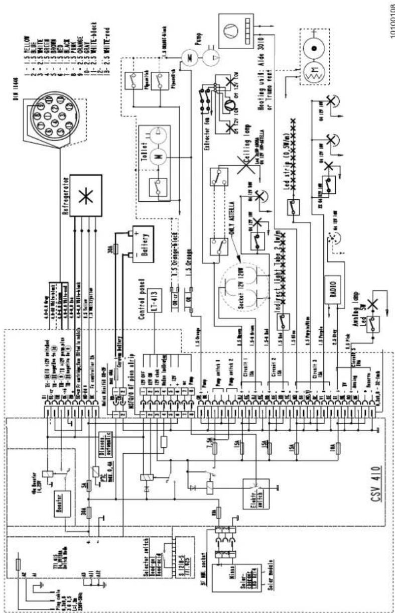
text_image
D18 11466 1-1.5 YELLOW 2-1.5 BLUE 3-2.5 WHITE 4-1.5 GREEN 5-1.5 BROWN 6-1.5 RED 7-1.5 BLACK 8-1.5 PAIN 9-2.5 ORANGE 10-2.5 GRAT 11-2.5 WHITE-Axlect 12-2.5 WHITE-red Refrigerator 6x4.4 power 6x4.4 white-tau 6x4.4 black-tau 6x4.4 red-tau 6x4.4 blue-tau 6x4.4 orange-tau 6x4.4 black-tau 6x4.4 white-tau 6x4.4 black-tau 6x4.4 white-tau 6x4.4 black-tau 6x4.4 white-tau 6x4.4 black-tau 6x4.4 white-tau 6x4.4 black-tau 6x4.4 white-tau 6x4.4 black-tau 6x4.4 white-tau 6x4.4 black,tau 6x4.4 white-tau 6x4.4 black-tau 6x4.4 white-tau 6x4.4 black-tau 6x4.4 white-tau 6x4.4 black-tau 6x4.4 white-tau 6x4.4 black-tau 6x4.4 white-tau 6x4.4 black-tau 6x4.4 white-taut 6x4.4 black-taut 6x4.4 white-taut 6x4.4 black-taut 6x4.4 white-taut 6x4.4 black-taut 6x4.4 white-taut 6x4.4 black-taut 6x4.4 white-taut 6x4.4 black-taut 6x4.4 white-taut 6x4.4 black-taut 6x4.4 white-tautFig. 67 Electrical diagram 12 V appliances: ADORA-ASTELLA
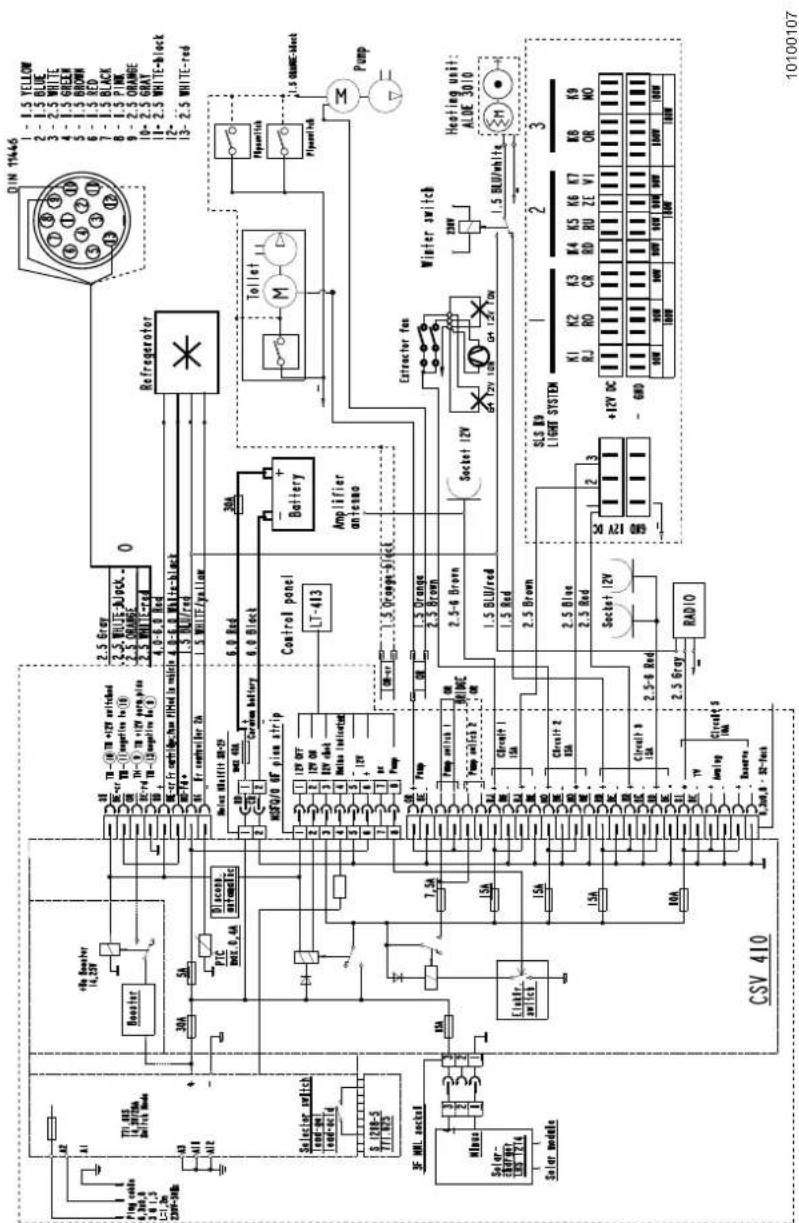
text_image
DIN 11446 1 - 1.5 YELLOW 2 - 1.5 BLUE 3 - 2.5 WHITE 4 - 1.5 GREEN 5 - 1.5 BROWN 6 - 1.5 RED 7 - 1.5 BLACK 8 - 1.5 PINK 9 - 2.5 ORANGE 10 - 2.5 GRAT 11 - 2.5 WHITE-block 12 - 13 - 2.5 WHITE-red TII 485 14,397MA Switch Mode A2 A1 A3 A18 A12 30A 5A PTC MAX: 0.6A Diacogon automatics Selector switch load-up load-out d S 128-5 TIT 852 3F MNL socket Mines Solar- ENERP/INT LRS T214 Solar modela +SB Booster 14,25V 8A 15A 15A 15A 15A 15A 15A 15A 15A 15A 15A 15A 15A 15A 15A 15A 15A 15A 15A 15A 15A 15A 15A 15A 15A 15A 10A 10V Amplig Circuit 9 1kA Circuit 9 1kA Circuit 9 1kA Circuit 9 1kA Circuit 9 1kA Circuit 9 1kA Circuit 9 1kA Circuit 9 1kA Circuit 9 1kA Circuit 9 1kA Circuit 9 1kA Circuit 9 1kAFig. 68 Electrical diagram 12 V appliances: ALPINA
11 Gas system
11.1 General information about the gas system
Familiarise yourself with the safety instructions for handling gas.
For general safety instructions concerning the topic of "gas", see the "Safety instructions for the gas system" (Chapter 2.5).
Danger!
Poisoning by gas
▲ If it smells of gas or you suspect that gas is escaping, perform the following:
→ Clear the danger area!
→ Close the shut-off valve on the gas cylinder!
→ Avoid ignition sources and open flames and do not smoke!
→ Ventilate the rooms!
→ Inform the camping site manager, and the fire brigade when necessary!
Warning!
Danger to life
▲ Have repairs or modifications of the gas system performed by an authorised workshop only!
▲ Never modify the gas system or appliances yourself!
▲ Never use a lighter or other open source of light at the junctions of the gas pipes to look for leaks!
▲ The user may make only the connection between the pressure regulator and the gas cylinder! Any other work has to be performed by an authorised workshop!
i Important!
- The complete gas system in the vehicle is designed for an operating pressure of 30 mbar which is kept constant by the built-in pressure regulator.
• After the expiration of two years and after the performance of modifications and repairs, the gas system must be inspected again. Always have a gas leak test performed on this occasion. The vehicle owner is responsible for initiating the inspection. Upon delivery of the vehicle, the operator must be informed in writing of his/her duty to have the gas system inspected. The correct condition of the gas system is confirmed with a gas inspection certificate. The associated gas inspection sticker must be attached to the rear of the vehicle near the license plate. - The gas regulator and the gas hose must be replaced every ten years.
- The complete gas system has been designed according to the valid technical regulations for liquid gas equipment and burners in camping vehicles. This was examined and certified by an expert.
-
All installed gas-operated appliances have safety devices. When the flame goes out, the automatic flame failure device interrupts the gas supply. In spite of this safety device, the respective quick-action stop valve must be closed if the appliance is not in operation.
-
In order to ensure continuous exchange of air in the vehicle, do not cover the forced ventilation in the roof hoods and in the entrance nor the mushroom ventilators.
- When there is snowfall in winter, keep the forced ventilation free from ice and snow! (Chapter 17.3).
11.2 Gas cylinder compartment

Caution!
Gas cylinder compartment
▲ Always keep the forced ventilation in the floor free!
▲ Always keep gas cylinders upright and lashed.
▲ Do not use the gas cylinder compartment as storage space. Danger of fire!
The gas cylinder compartment is accessible from the outside only.
The gas cylinder compartment is intended for storing the gas cylinders. Do not cover the forced ventilation.
Secure the gas cylinder compartment against unauthorised access.
11.3 Gas types
The gas-operated appliances are operated with liquid gas (propane, butane or a mixture of both).
The dealers offer mainly 5 kg or 11 kg gas cylinders for purchase or hiring.
Handling gas cylinders
→ Store gas cylinders exclusively in the gas cylinder compartment.
→ Lock the gas cylinder compartment securely against unauthorised access!
11.3.1 Propane gas
Propane is a colourless and odourless gas. Propane is capable of gasification down to -42^ C.
Propane is suitable for winter camping.
Propane is highly flammable, heavier than air and, in high concentrations, has a narcotising to suffocating effect.
11.3.2 Butane gas
Butane occurs in two different versions (isomers): Isobutane and n-butane.
Isobutane and n-butane are liquid gases that are generated when crude oil is distilled.
Isobutane gasifies at -12^ , n-butane at -0.5^ . This means, butane is unsuitable for use in winter. Between the seasons, a mixture of butane and propane gas can also be used.
11.3.3 Information on liquid gas
Liquid gas characteristics:
- Liquid gas has no colour.
- It smells of garlic.
- It is heavier than air and collects on the ground after escaping.
- It is combustible and can burn rapidly when it escapes uncontrolled or explode when sparks occur.
• In enclosed areas, it displaces the breathing air; risk of suffocation!
11.4 Reference values for gas consumption
The gas consumption depends on how intensively the connected appliances are used.
| Appliance Refer- | ence value | Unit |
| Gas heater 170 - 490 g/h | ||
| Cooker 100 - 400 g/h | ||
| Refrigerator 10 - 25 g/h | ||
| Oven 50 - 200 g/h |
Tab. 9 Reference values for gas consumption
11.5 Handling gas cylinders

Caution!
Danger when handling gas cylinders
▲ Read the safety instructions on the gas cylinder!
▲ Operate gas cylinders only with the pressure regulator connected!
▲ Do not smoke in the vicinity of the gas cylinders! Any kind of open flame must be avoided! This is valid in particular when replacing gas cylinders.
▲ Never lubricate threads and seals on the pressure regulator with grease. Risk of explosion by chemical reactions!
▲ The vents in the floor of the gas cylinder compartment always have to be kept uncovered.
▲ Use only gas cylinders provided for the camping sector!
▲ Never use special cylinders from other areas of application!
▲ Gas cylinders that are not connected must always be secured with a protective cap.
▲ The protective cap for the connected gas cylinder must be on board.
▲ Pay attention to the inspection date on the gas cylinder!
▲ Fill gas cylinders only by weight. This applies also for foreign countries!
▲ Never use city gas or natural gas!
▲ Never fill gas cylinders at propellant gas stations. Risk of explosion!
▲ If the vehicle is parked for a longer period of time, the gas cylinders may remain in the vehicle only when it is parked outdoors!
▲ The gas cylinder compartment is designed for a maximum of two 11 kg gas cylinders.
The gas cylinders are not part of the delivery items of the vehicle and have to be bought and connected by the operator.
Take utmost care when handling gas cylinders.
Grey gas cylinders with red marking (protective cap and bottom ring) are purchased cylinders and can be replaced or filled.
11.6 Quick-action stop valves

Important!
If the gas appliance is not used, the respective quick-action stop valve must be closed.
The gas distribution to the individual gas appliances is performed via the gas quick-action stop valves.
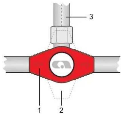
text_image
1 2 3Fig. 69 Quick-action stop valves - positions
1 Closed
2 Open
3 Gas pipe to the gas appliance
Using the gas appliances:
→ Open the respective quick-action stop valve to put the desired gas appliance into service.
- Quick-action stop valve closed (Fig. 69/1): The arrows on the quick-action stop valve are positioned on the gas appliance crosswise to the direction of the gas pipe (Fig. 69/3).
- Quick-action stop valve open (Fig. 69/2): The arrows on the quick-action stop valve are positioned in the direction of the gas pipe to the gas appliance (Fig. 69/3).
11.6.1 Quick-action stop valves of heater, refrigerator, cooker and oven
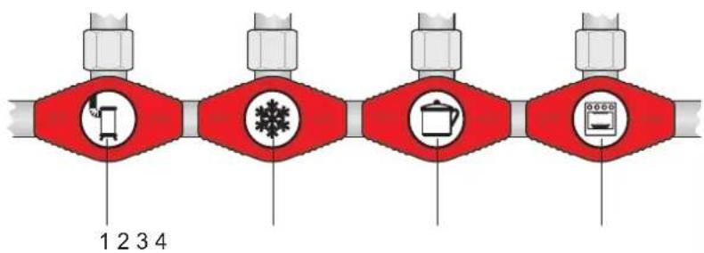
text_image
1 2 3 4Fig. 70 Quick-action stop valves of heater, refrigerator, cooker and oven
1 Heater
2 Refrigerator
3 Cooker
4 Oven
Each gas appliance has its own quick-action stop valve.
These are marked with suitable symbols to prevent mistakes:
- Heater (Fig. 70/1)
• Refrigerator (Fig. 70/2)
• Cooker (Fig. 70/3)
- Oven (Fig. 70/4)
11.7 External gas connection (special equipment)

Danger!
Risk of explosion
▲ Only use a suitable adapter to connect to the external gas connection.
▲ Only connect gas appliances to the external gas connection that are designed for 30 mbar operating pressure.
▲ Check leak tightness of the external gas connection every time a gas appliance is connected. Gas escapes into the air when the gas connection leaks.
▲ Close the stopcock and main shut-off valve on the gas cylinder immediately when gas escapes and have the external gas connection checked by an approved specialist workshop.
▲ No fire, no smoking and no sparks when connecting a gas appliance to the external gas connection.
▲ Filling gas cylinders using the external gas connection is forbidden. Observe the information sticker.
▲ Always close the stopcock when no appliance is connected to the external gas connection.
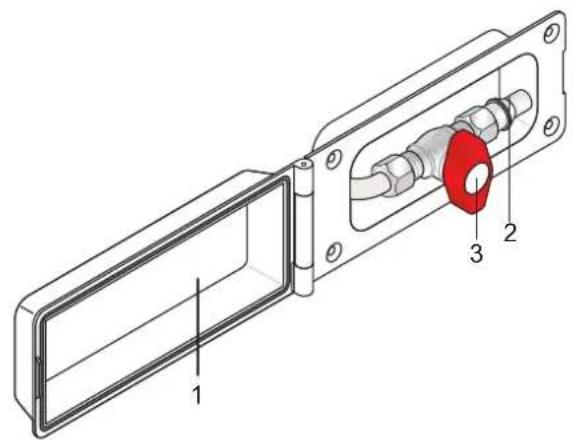
text_image
Technical diagram of a mechanical assembly with numbered components labeled 1, 2, and 3Fig. 71 External gas connection
1 External gas connection cover
2 Connection for gas appliances
3 Stopcock
Using the external gas connection:
→ Open the flap for the external gas connection (Fig. 71/1)
→ Attach a suitable adapter to the connection (Fig. 71/2).
→ Open the stopcock (Fig. 71/3).
12 Water and waste water
12.1 Water supply
Health hazard
▲ Formation of bacteria and algae in the water tank.
→ Change the water at regular intervals including the boiler contents (e.g. twice a week).
→ After the end of every journey or after 4 weeks at the latest, the water tank must be drained, cleaned thoroughly and left open (venting).
→ Use disinfectant for the water tank.
Damage to the water pump
▲ Pumps can run hot without water and can be damaged.
▲ Never run pumps when the water tank is empty!
Damage to the environment
▲ Never drain tanks (water and waste water) in the open countryside!
▲ Empty tanks only at petrol stations, resting places, disposal stations or camping sites at the provided places.
Damage due to frost
▲ When there is a risk of frost, drain the water system of the vehicle.
When a water tap is opened, the installed water pump is switched on.
Using the water tank:
→ Thoroughly clean the water tank before starting each journey.
→ If possible, fill the water tank only just before staying overnight or at the destination of the journey.
→ Avoid additional weight.
→ Fill the water tank with drinking water only.
When the vehicle is placed out of service for an extended period of time or is not heated when there is a risk of frost, empty, clean and dry the entire water system (Chapter 12.2). Leave the water taps and drain cocks as well as all drain valves open.
We recommend to check the pipes every 6 months for leaks and to tighten the clamps as well as the connectors.
The water supply system corresponds to the state of technology (Directive 2002/72/EC).
12.1.1 Water tank
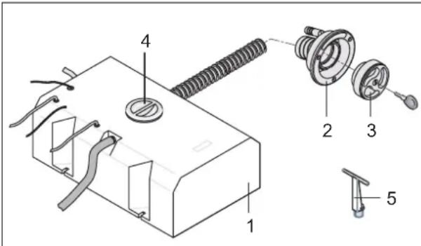
text_image
Technical diagram of a mechanical assembly with labeled parts including spring, housing, and adjustment partsFig. 72 Filling the water tank - external
1 Water tank
2 Filler neck
3 Lockable cap
4 Service cover
5 Drain plug
Filling the water tank (external):
→ Switch the water pump off (actuate the button on the control panel, Chapter 8.6).
→ Unlock and open the lockable cap (Fig. 72/3) on the filler neck (Fig. 72/2).
→ Fill water with a water canister, a watering can or a hose into the water tank.
→ Replace, close and lock the cap.
Draining/cleaning the water tank:
→ Switch the water pump off (actuate the button on the control panel, Chapter 8.6).
→ Open the service cover (Fig. 72/4).
→ Open the drain plug on the tank bottom (Fig. 72/5).
→ Drain the water tank completely.
→ Clean the inside of the tank.
→ Reinsert the drain plug (Fig. 72/5) in the drainage opening and close the service cover (Fig. 72/4).
12.1.2 Ultraflow external water connection (special equipment)
Some vehicles are fitted with an external water connection (Truma Ultraflow). The external water connection can only be used with a suitable adapter. Depending on the equipment, separate water consumers can be connected to the external water connection (e.g. outdoor shower) or to an external water tank.
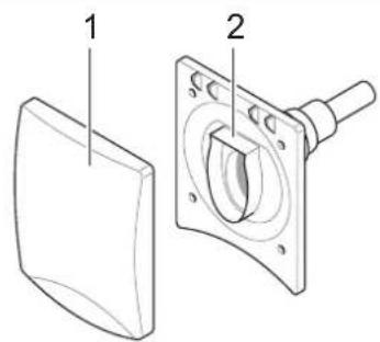
text_image
Technical diagram showing two views of a mechanical component with labeled parts 1 and 2Fig. 73 Ultraflow external water connection
1 External water connection flap
2 Socket with switch contacts
Using the external water connection:
→ Open the flap (Fig. 73/1) of the external water connection.
→ Connect a suitable plug (Truma Ultraflow) to the socket (Fig. 73/2).
The external accessory is now connected to the onboard system.
12.1.3 City water connection (special equipment)
Some vehicles are fitted with a city water connection which can only be used with a suitable adapter (type Gardena).
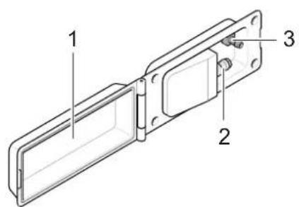
text_image
Technical diagram of a mechanical assembly with labeled parts 1, 2, and 3Fig. 74 City water connection
1 City water connection flap
2 Plug nipple (type Gardena)
3 Water pump switch
i Important!
- Check the fill level of your waste water container at regular intervals.
- Check the external water pressure, maximum allowable water pressure: 10 bar.
→ Open the flap (Fig. 74/1) of the city water connection.
→ Attach a suitable adapter to the plug nipple (Fig. 74/2).
→ Switch the switch (Fig. 74/3) to city connection. The onboard water pump is switched off. Opening a tap activates the city water connection.
12.1.4 Faucet
Drawing of hot and cold water is performed with a single-lever faucet.
Depending on the installation position, the water temperature is controlled either by raising and lowering or swivelling of the lever
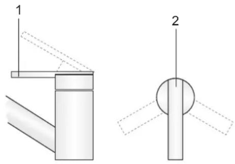
text_image
1 2Fig. 75 Faucet
1 Lever (raising/lowering)
2 Lever (swivelling)
Operating the faucet:
→ Move the lever (Fig. 75/1) upward to turn on the water pump.
Water is running.
→ Adjust the desired temperature by swivelling the lever (Fig. 75/1).
→ Lever in the "red" direction: The water becomes warmer.
→ Lever in the "blue" direction: The water becomes cooler (minimum ambient temperature of the water tank).
→ Push the lever (Fig. 75/1) fully downward to stop the water.
12.1.5 Waste water tank, mobile (special equipment)
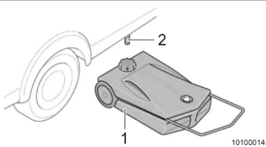
text_image
1 2 10100014Fig. 76 Waste water tank, mobile
1 Waste water tank
2 Drain pipe
The drain pipe (Fig. 76/2) is located at the vehicle bottom on the left in driving direction.
Positioning the waste water tank:
→ Open the cap of the waste water tank and stow away safely.
→ Position the waste water tank under the drain pipe so that no water drains outside the waste water tank.
→ Check the level of the waste water tank at regular intervals and dispose of waste water in time in an approved drain.
12.2 Draining the water and waste water system

Warning!
Health hazard
▲ Prevent the formation of bacteria and algae in the water tank.
→ Change the water at regular intervals including the boiler contents (e.g. twice a week).
→ After the end of every journey, the water tank including the boiler must be drained, cleaned thoroughly and left open (venting).
→ Thoroughly clean the hoses after the end of each journey.
→ Use disinfectant for the water tank.

Caution!
Damage due to frost
▲ Prevent frost damage to the water system.
If the vehicle is not heated when there is a risk of frost (winter), damage to the components of the water or waste water system can occur due to the formation of ice. Drain all water-conducting components.
When the vehicle is placed out of service for an extended period of time or is not heated when there is a risk of frost, empty and clean the entire water system and allow to dry. Leave the water taps and drain cocks as well as all drain valves open.
Draining the water supply:
→ Switch the water pump and the boiler off or disconnect electrical plug connection.
→ Open all water taps to the centre position.
→ Empty the water tank (Chapter 12.1.1)
→ Open the boiler safety valve (Chapter 13.1.7).
→ The tank must be rinsed, cleaned and allowed to dry.
→ On vehicles with pressure pump, switch the pump on for a short time to remove residual water.
→ Leave all water taps open in the centre position until the vehicle is placed into service again. The water pump may be switched on only when water has been filled.
Emptying the waste water system:
→ Allow the waste water to flow into the waste water tank.
→ Drain the waste water tank at the intended waste water disposal station.
→ Leave the drain cocks as well as all drain valves open.
13 Heater & hot water
13.1 General heating information

Danger!
Risk of fire
▲ The person using the heating must have the heat exchanger of the Truma heating replaced at the latest after 30 years. Only the heating manufacturer or an authorized workshop can exchange the heat exchanger.
▲ Heating spare parts must always be approved as spare parts by the manufacturer.

Danger!
Risk of explosion
▲ Never let unignited gas flow out.
▲ Switch the heater off before filling the fuel tank, when on ferries and in garages.

Danger!
Risk of poisoning
▲ Before placing the gas heater into service in winter operation, check the cowl on the caravan roof is free from snow and ice.
▲ Check the exhaust gas pipe for damage before switching the heating on. Do not use the heater with a damaged exhaust gas pipe.
▲ Do not close off or cover the exhaust cowl.
▲ Use cowl extensions during winter camping, snow must not cover the exhaust cowl.
▲ Do not use the space behind the heating for storage.
13.2 Warm air heater
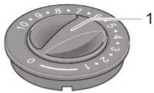
text_image
10 9 8 7 6 5 4 3 2 1 0Fig. 77 Control knob, warm air heater
1 Control knob
Switching the warm air heater on with electric ignition:
→ Open the shut-off valve on the gas cylinder and the quick-action stop valve of the heater.
→ Set the control knob (Fig. 77/1) on the heater to the desired setting and press it down to the stop.
The ignition creates ignition sparks. A clicking noise can be heard.
→ Keep the control knob pressed until the flame can be seen in the inspection window in the heater cover.
→ Keep the control knob pressed for about another 10 seconds so that the safety pilot switches on.
Switching the warm air heater off:
→ Set the control knob (Fig. 77/1) of the heating to "0".
→ If the heating is not going to be used for some time, close the quick-action stop valve "Heating" and the shut-off valve on the gas cylinder.
For more information, see the separate instructions from the manufacturer.
13.3 Circulation fan (special equipment)
The circulation fan allows better circulation of the warmth from the warm air heater.
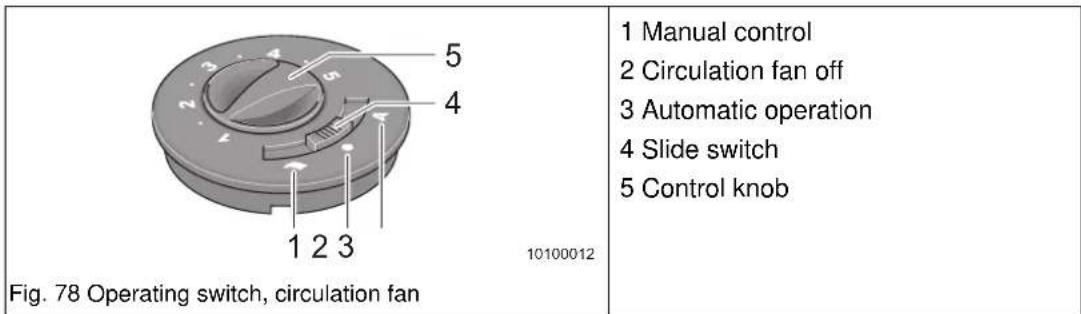
Switching the circulation fan on:
→ Set the desired operating mode with the slide switch (Fig. 78/4).
– (1) Manual control (e.g. ventilation)
- (2) Circulation fan "Off" (switch setting not effective during heating)
– (3) Automatic operation (heating)
In manual operation (Fig. 78/1), use the control knob (Fig. 78/5) to set the desired level of the circulation fan or to limit the level during automatic operation (Fig. 78/3).
For more information, see the separate instructions from the manufacturer.
13.4 Ultraheat auxiliary electric heater (special equipment)
The Ultraheat auxiliary electric heater is integrated in the warm air heater. The auxiliary electric heater heats the vehicle faster.
Fitting this unit provides three operating modes for the warm air heater:
- Warm air heater only
- Warm air heater and electric heater together
• Electric heater only
The auxiliary electric heater has three capacity levels:
Fig. 79 Ultraheat control with room thermostat
1 Rotary switch for levels
2 "Off" position
3 Temperature controller
Switching Ultraheat on:
→ Connect the vehicle to the 230 V supply (see Chapter 10.1.1).
→ Turn the rotary switch (Fig. 79/1) to the desired capacity level 500 W, 1000 W or 2000 W.
→ Set the thermostat (Fig. 79/3) to the desired temperature.
Switching Ultraheat off:
→ Set the rotary switch to (Fig. 79/1) "Off" (Fig. 79/2).
For more information, see the separate instructions from the manufacturer.
13.5 Electrical floor heating (special equipment)
Depending on the model and special equipment, your vehicle has been fitted with floor heating. The floor heating serves to heat the floor surfaces in your vehicle slightly.

Danger!
Risk of electric shock or short-circuit
▲ Do not drill any holes or screw in any screws in the floor when the vehicle is fitted with electrical floor heating.

Danger!
Risk of overheating
▲ Do not cover the transformer.
You can only use the floor heating when the vehicle is connected to a 230 V supply.
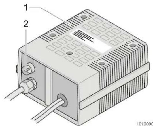
text_image
1 2 1010000Fig. 80 "Electrical floor heating" transformer
1 Transformer
2 Overload protection pin
The transformer (Fig. 80/1) for the electric floor heating is fitted in the seat chest or bed box depending on the model.
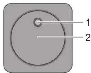
text_image
1 2Fig. 81 "Electrical floor heating" switch
1 Control lamp
2 Rocker switch
Using the electrical floor heating:
→ Check the circuit protection for the 230V power supply at the camping site is adequate.
(350 W - 1.5 A)
→ Check the connection cable is wound off fully from the cable reel.
→ Check the 230 V circuit breaker in the vehicle is switched on.
→ Check the mains plug of the transformer is connected to a 230 V socket.
→ Press the rocker switch (Fig. 81/2). The control lamp (Fig. 81/1) in the switch goes on.
Switching the electrical floor heating off:
→ Press the rocker switch (Fig. 81/2). The control lamp in the switch (Fig. 81/1) goes off.
→ The floor remains warm for some time after switching off due to residual heat.
The electrical floor heating has an overload protection. The overload protection triggers when the transformer is overloaded. The pin (Fig. 80/2) springs out.
→ When the transformer has cooled down, push the pin (Fig. 80/2) on the overload protection back in again.
For more information, see the separate instructions from the manufacturer.
13.6 Truma Therme (special equipment)
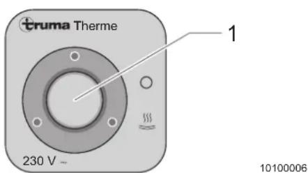
text_image
truma Therme 230 V ~ 1 10100006Fig. 82 Truma Therme rocker switch
1 Switch
You can run the Truma Therme with either the 230 V supply (electric model), with warm air from the heating system or with both types of energy. The Truma Therme heats about 5 l of water to maximum 65°C.
The switch serves to start (Fig. 82/1) the electric operating mode. The control lamp in the switch is on during operation.
In warm air operation, the water in the Therme is heated by the heater air flow.
Filling the Truma Therme with water:
→ Check that the Truma Therme switch is switched off (Fig. 82/1). The control lamp must be off.
→ Turn the drain cocks (Fig. 83/1) clockwise to close.
→ Open all water taps in the vehicle to "Hot". The water pump now runs.
→ Leave the taps open until the water flows out without bubbles. The boiler is now filled with water.
→ Close all taps.
Running the Truma Therme with electricity:
→ Connect the vehicle to the 230 V supply.
→ Switch the rocker switch (Fig. 82/1) for the Truma Therme on. The control lamp in the switch goes on. The water in the Truma Therme is heated to maximum 65 °C.
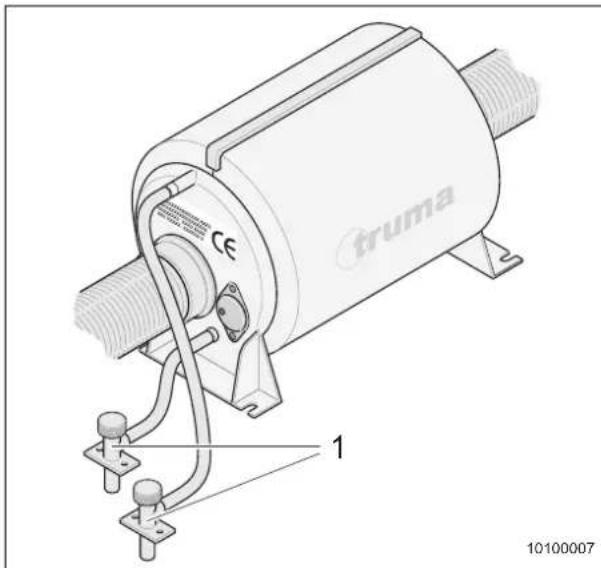
text_image
truma 1 10100007Fig. 83 Truma Therme
1 Drain cocks
Emptying the Truma Therme :
→ Place a collector under the drain openings of the drain cocks.
→ Switch the rocker switch (Fig. 82/1) for the Truma Therme off. The control lamp in the switch is off.
→ Open all taps.
→ Turn the drain cocks (Fig. 83/1) anticlockwise to open.
→ Check that the Therme is completely empty.
→ Dispose of the water collected at an approved location.
For more information, see the separate instructions from the manufacturer.
13.7 Truma Boiler (special equipment)

Danger!
Risk of poisoning and suffocation when the exhaust cowl is fitted on the right
When the awning is in place and the heater operates in gas mode, the heater exhaust gases can collect under the awning. There exists the risk of poisoning and suffocation due to lack of oxygen and the possibly generated odourless and toxic carbon monoxide (CO).
▲ Ensure adequate ventilation!

Caution!
Type of danger
▲ Never run the boiler without water.
▲ When the boiler is not in use, empty it when there is a risk of frost.
▲ Switch the boiler off and empty it when the vehicle is not in use.
The boiler can be run with either gas or power from the 230 V supply. The 12 V supply supplies voltage to the electric boiler control.
To speed up water heating, the Truma Boiler can be run with both gas and electricity.
13.7.1 Filling/emptying the boiler
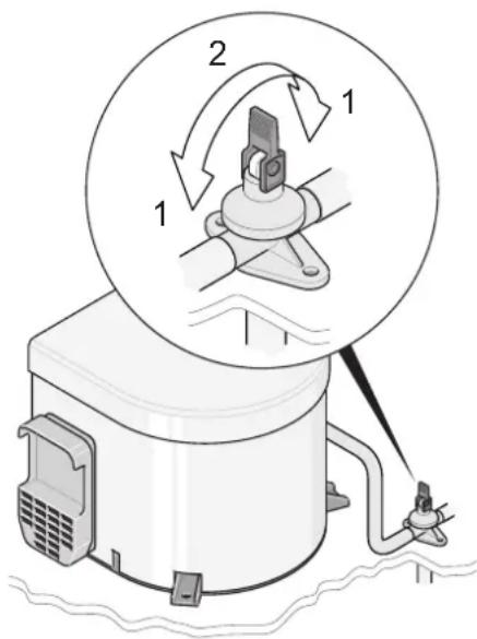
text_image
Diagram of a refrigerator with labeled parts and a circular diagram showing mechanical components and rotation direction.Fig. 84 Boiler safety/drain valve
1 Drain cock closed
2 Drain cock open
The boiler is supplied with water from the water tank.
Filling the boiler with water:
→ Close the safety/drain valve (Fig. 84/2). To do this, turn the rocker arm horizontal.
→ Switch on the 12 V supply.
→ Open all water taps in the vehicle to "Hot". The water pump now runs.
→ Leave the taps open until the water flows out without bubbles. The boiler is now filled with water.
→ Close all taps.
Emptying the boiler:
→ Place a collector under the drainage opening of the drain cock.
→ Switch off the rocker switch for electric operation (Fig. 86/1) and the rotary knob for gas operation (Fig. 85/3). The control lamps in the switches are off.
→ Switch off the 12 V supply.
→ Open all taps.
→ Open the safety/drain valve (Fig. 84/2). To do this, set the rocker arm vertical.
→ Check that the boiler is completely empty.
→ Dispose of the water collected at an approved location.
For more information, see the separate instructions from the manufacturer.
13.7.2 Boiler in gas mode
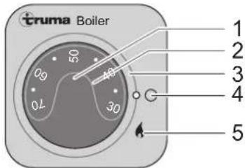
text_image
Truma Boiler 1 2 3 4 5Fig. 85 Boiler operating unit in gas mode
1 Temperature rotary knob
2 Control lamp for malfunctions (red)
3 "On/Off" rotary switch
4 Off
5 On
Switching the boiler on in gas mode:
→ Remove the cowl flap.
→ Open the main shut-off valve on the gas cylinder and "Boiler" quick-action stop valve.
→ Switch on the 12 V supply.
Set the rotary switch (Fig. 85/3) to "On" (Fig. 85/5). The green control lamp "Operation" goes on in the rotary knob (Fig. 85/1).
→ Set the desired water temperature on the rotary knob (Fig. 85/1).
The red control lamp (Fig. 85/2) goes on when a malfunction occurs. For more information, see the separate instructions from the manufacturer.
Switching the boiler off in gas mode:
→ Set the rotary switch (Fig. 85/3) to "Off" (Fig. 85/4).
→ Close the "Boiler" quick-action stop valve and the main shut-off valve on the gas cylinder.
→ Put the exhaust cowl flap back on.
The red control lamp (Fig. 85/2) goes on when a malfunction occurs.
For more information, see the separate instructions from the manufacturer.
13.7.3 Boiler in electric mode
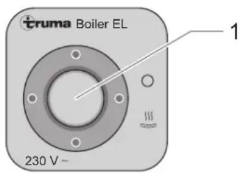
text_image
truma Boiler EL 230 V~ 1Fig. 86 Boiler rocker switch for electric mode
1 Rocker switch
The water temperature is preset to about 70^ C in e lectric mode and cannot be changed.
Switching the boiler on in electric mode:
→ Connect the vehicle to the 230 V supply.
→ Press the rocker switch (Fig. 86/1) at the top. The green control lamp "Operation" goes on.
Switching the boiler off in electric mode:
→ Press the rocker switch (Fig. 86/1) at the bottom. The green control lamp "Operation" is not on.
For more information, see the separate instructions from the manufacturer.

Important!
The electric heating rod is fitted with an overheat protection. If a malfunction occurs (water remains cold), switch the rocker switch off, wait about 10 minutes and then switch it on again.
13.8 Alde warm water heater
i Important!
Central heating Alde Compact has an "ionizing flame control", i.e. if the flame goes out, the electronic control panel attempts to ignite the flame again. If the flame does not ignite within 10 seconds, the solenoid valve shuts off the gas supply and the electronic control panel.
→ Reset by switching off and restarting the heater with the On/Off button (Fig. 87/8).
Central heating and warm water heater Alde Compact 3010 is controlled by the control panel. The control panel has a touch-sensitive display. Just pressing the display surface lightly serves to enter most of the settings.
13.8.1 Overview of symbols
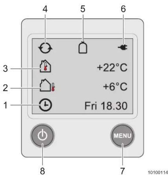
text_image
4 5 6 3 +22°C 2 +6°C Fri 18.30 1 7 MENU 8Fig. 87 Overview of control panel symbols
1 Clock
For setting the clock, see the separate instructions from the manufacturer.
2 Outside temperature
The outside temperature is indicated when the sensor has been installed.
3 Inside temperature
The inside temperature is indicated.
4 Circulation pump
The symbol is displayed when the pump is in operation.
5 Automatic cylinder switch-over
The symbol is displayed when automatic cylinder switch-over is connected and activated, see the separate instructions of the manufacturer.
6 230 Volt
The symbol is displayed when a voltage of 230 Volt is applied to the heater.
7 MENU button
Button for the settings menu.
8 On/Off button
Main switch of the heater.
13.8.2 Menu overview
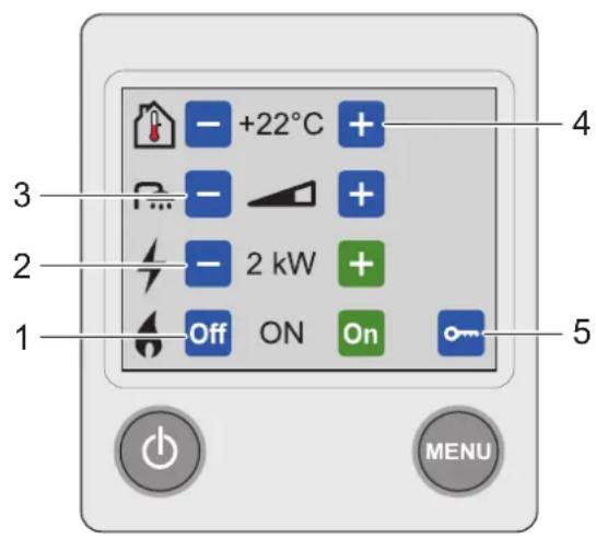
text_image
1 2 3 4 5 +22°C - - 2 kW Off ON On MENU10100115
Fig. 88 Overview of control panel menu
1 Heating with gas
Press the "On" button to switch gas operation on.
Press the "Off" button to switch gas operation off.
2 Heating with electricity
Select the power (Off, 1 kW, 2 kW or 3 kW) by pressing the "+" or "-" button. Some heaters only have 1 kW or 2 kW.
3 Hot water volume
Press the "+" button to increase the hot water volume for 30 min.
Press the "-" button to return to the basic settings for hot water before 30 min. have expired.
4 Room temperature
Press the "+" button to increase the temperature.
Press the "-" button to reduce the temperature.
5 Tools menu
For the settings, see the separate instructions from the manufacturer.
When the Menu button is actuated, background lighting comes on and the functions that can be set are displayed.
The performed settings are automatically saved after ten seconds. After two minutes, the control panel automatically switches to standby when no buttons are pressed.
13.8.3 Starting the heater

Caution!
Damage to heater
▲ Only authorised and qualified personnel may perform work on the electronic control panel of the central heating!

Important!
Heating with electricity is to be preferred to heating with gas.
→ Check the heater liquid level (Chapter 20.5).
→ In gas operation: Open the shut-off valve on the gas cylinder and the quick-action stop valve of the heater.
To start the heater, press the On/Off button (Fig. 87/8). The Start screen is displayed. The heater starts with the settings used last.
→ Control of central heating with the control panel (Fig. 88/1 to 5).
In summer, when only hot water is required, the set temperature value must be lower than the prevailing temperature to prevent a start of the pump in the heating system.
For more information, see the separate instructions from the manufacturer.
13.9 Exhaust cowl on the right side of the vehicle

Danger!
Risk of poisoning and suffocation
When the awning is in place and the heater operates in gas mode, the heater exhaust gases can collect under the awning. There exists the risk of poisoning and suffocation due to lack of oxygen and the possibly generated odourless and toxic carbon monoxide (CO).
▲ Ensure adequate ventilation!
13.10 Warm air distribution
natural_image
Cross-sectional diagram of a mechanical component with concentric layers and a labeled part (1), no text or symbols present.Fig. 89 Air outlet nozzle
1 Air outlet nozzle
Several air outlet nozzles (Fig. 89/1) are built into the vehicle. Pipes and flexible hoses conduct the warm air to the nozzles.
Distributing the warm air:
→ Adjust the air outlet nozzles (Fig. 89/1) so that the warm air escapes at the desired positions only.
Adjusting the air outlet nozzles:
→ Fully open the air outlet nozzle (Fig. 89/1) to conduct the full warm air flow to the desired position.
The more the air outlet nozzle is closed (Fig. 89/1), the less warm air flows out.
The more air outlet nozzles are open, the less warm air flows out at the individual nozzles.
14 Cooking
14.1 Cooking with gas

Danger!
Risk of poisoning due to carbon monoxide (CO) and lack of oxygen
▲ Always open a window or a skylight as well when the gas stove is switched on.
▲ Never cover the forced ventilation in the roof hoods and in the entrance as well as the mushroom ventilators.

Danger!
Risk of explosion
▲ Never allow the gas to flow out unburned because of the risk of explosion!
If a flame of the gas stove extinguishes, unburned gas flows out until the flame failure device is activated and together with the oxygen generates an explosive mixture inside the vehicle!
▲ Watch the flames while using the cooker!
▲ When finished, shut the respective quick-action stop valve (Chapter 11.6.1).
Observe the following when operating the gas stove:
→ Always open a window or a roof hood (Chapter 8.2).
This supplies the vehicle with sufficient oxygen and leads away cooking vapours.
→ Do not keep combustible objects, e.g. tablecloths, napkins, etc. near the gas stove. Risk of fire!
→ Carefully observe the ignition process. The view must not be obstructed.
→ Place the pots on the middle of the cooking positions.
→ Use only pots with flat bottoms that are not larger than the respective gas burner grate.
→ Do not allow the flames to extend beyond the pot edge.
→ Always use cooking gloves or pot holders when handling hot pots, pans and similar items. Risk of injury!
→ Never use the gas stove for heating.
Observe the following for the glass cover (special equipment):
→ Do not apply pressure on the glass gas stove cover when closed.
→ Do not close the glass cover while burners are still in operation or emit heat.
→ Do not place hot cooking pans on the glass cover.
→ In the case of frost, keep the kitchen window closed and provide ventilation in a different way. Otherwise, the temperature difference on the glass cover could cause damage.
14.2 Gas stove

Caution!
Defective cooking area
▲ The burner does not operate properly. The flame goes out again and again despite the control knob being depressed for an extended period of time.
▲ The thermal element is bent or defective. Have defective thermal elements replaced by an authorised workshop. We recommend yearly inspection by a specialist.

Important!
- Always make sure the respective control knob is set to "Off" when you are finished using the cooking stove, the grill or the oven.
- On models with electric ignition, proceed in the same manner as described, however, the flame is ignited by pressing the button for electric ignition on the control panel. The ignition of the oven and of the grill must be performed with the door open.
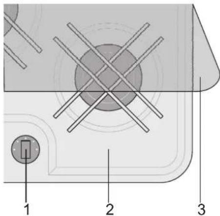
text_image
Technical diagram showing labeled components of a device or circuit board with numbered parts 1, 2, and 3.Fig. 90 Gas stove
1 Control knob
2 Cooking area
3 Glass cover
Using the gas stove correctly:
→ Clean the gas stove before placing it into service (Chapter 19.2.5).
→ Lift the glass cover (Fig. 90/3) of the cooking area (Fig. 90/2) up.
→ Open the shut-off valve of the gas cylinder and the quick-action stop valve (Fig. 69/3) on the distributor block.
→ Turn the control knob (Fig. 90/1) of the desired cooking position (Fig. 90/2) to "large flame", press it and keep it depressed.
Gas flows out.
Ignite the gas flowing out with a suitable device and keep the control knob (Fig. 90/1) depressed for approx. 10 s until the safety pilot valve keeps the gas supply open.
→ If the flame goes out, repeat the process.
Regulate the gas supply by turning the control knob to the "large flame" or "small flame" symbol.
To switch off, turn the control knob clockwise to the "0 position".
The flame goes out and the flame safety device automatically shuts off the gas supply.
☐ Close the quick-action stop valve (Fig. 69/3).
For more information, see the separate instructions from the manufacturer.
14.3 Extractor hood (special equipment)
The extractor hood is located above the gas stove.
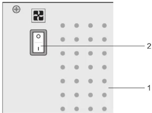
text_image
Diagram showing a device panel with labeled components and dot grid layout, including numbered annotations 1 and 2.Fig. 91 Extractor hood - version 1
1 Extractor hood
2 Rocker switch
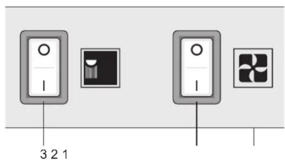
text_image
3 2 1Fig. 92 Extractor hood - version 2
1 Extractor hood
2 Extractor hood rocker switch
3 Lighting rocker switch
Using the extractor hood:
Use the rocker switch (Fig. 91/2), (Fig. 92/2) to switch on the extractor hood during cooking (Fig. 91/1), (Fig. 92/1). This prevents condensing water vapour and unpleasant odour in the vehicle.
☐ On some vehicles, you can switch on the lighting of the cooking area with the rocker switch (Fig. 92/3) on the extractor hood.
For more information, see the separate instructions from the manufacturer.
14.4 Microwave oven (special equipment)
Danger!
Danger for health
▲ Only allow qualified personnel to repair he microwave oven. Serious health risk through incorrect repairs!
▲ Do not remove the protection against microwave energy escaping.
▲ Do not use the microwave oven when the door seal is damaged.
▲ Do not leave the microwave oven unattended when in use.
▲ If smoke occurs, switch microwave oven off and disconnect the power supply. Leave the microwave oven closed.
i Important!
We point out explicitly that we will not assume any liability for damage and malfunctions resulting from the nonobservance of this instruction manual.
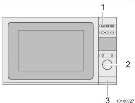
text_image
1 2 3 10100027Fig. 93 Microwave oven
1 Capacity switch
2 Cooking time control
3 Door opener
Switching the microwave oven on:
→ Push the door opener (Fig. 93/3) to open the door and put the food in the cooking space.
→ Close the door. It closes with a click.
→ Press the capacity switch (Fig. 93/1) once or several times to select the capacity.
→ Select the cooking time on the cooking time control (Fig. 93/2).
Cooking starts.
Switching the microwave oven off:
A signal tone indicates when the cooking time has elapsed. The microwave oven switches off independently.
→ Press the door opener (Fig. 93/3) and take the food out.
For more information, see the separate instructions from the manufacturer.
14.5 Gas stove with grill and oven (special equipment)

Warning!
Risk of burns by hot surfaces
▲ Always wear protective gloves when handling hot items.
▲ Protect yourself and your children from contact with hot parts.
▲ After use, allow the grill and the oven to sufficiently cool down inside and outside.

Caution!
Damage to oven
▲ Never use the oven for heating the vehicle!
14.5.1 Operation

Important!
- Always make sure the respective control knob is set to "Off" when you are finished using the cooking stove, the grill or the oven.
- On models with electric ignition, proceed in the same manner as described, however, the flame is ignited by pressing the button for electric ignition on the control panel. The ignition of the oven and of the grill must be performed with the oven door open.
All flames are individually controlled and each single flame is monitored by the sensor of a thermal element. If flames are extinguished by mistake, switch them off and wait at least one minute before trying to ignite them again.
Using the cooking stove:
→ Make sure the gas supply is connected and switched on. Open the quick-action stop valve for the cooker.
→ Press the control knob and turn it anticlockwise until it is fully open - towards the large flame symbol.
→ Keep the control knob depressed while holding a lit match to the burner.
→ When the flame is burning, keep the control knob depressed for another 10 to 15 seconds.
→ Release the control knob and set the desired flame level.
→ If the flame does not ignite within 15 seconds, release the control knob and wait at least one minute before repeating steps 2 to 5.
→ To switch off the flame, turn the control knob until the line on the control knob points to the mark on the control panel.
Using the grill:
→ Make sure the gas supply or the gas cylinder are connected and switched on.
→ Open the door, press the control knob and turn it clockwise to the large flame symbol.
→ Keep the knob depressed while holding a lit match to the burner.
→ When the flame is burning, keep the knob depressed for another 10 to 15 seconds.
→ If the flame does not ignite within 15 seconds, release the control knob and wait at least one minute before repeating steps 2 to 4.
→ To switch off the flame, turn the control knob until the line on the control knob points to the mark on the control panel.
Using the oven:
→ Make sure the gas supply or the gas cylinder are connected and switched on.
→ Open the door, press the control knob and turn it to the stop (setting 9, 240 °C).
→ Keep the knob depressed and hold a lit match to the burner.
→ When the flame is burning, keep the knob depressed for another 10 to 15 seconds.
→ Release the knob and set the desired flame.
→ If the flame does not ignite within 15 seconds, release the control knob and wait at least one minute before repeating steps 2 to 5.
→ Position the grate into the required position and close the door.
→ Although the oven heats up quickly, it is advisable to allow 10 minutes preheating time. The oven should reach its full temperature within 15 to 20 minutes.
→ To switch off, turn the knob until the line on the knob is aligned with the mark on the control panel.
Adjusting the temperature:
| Gas setting Temperature Middle of the oven | Dish | |||
| 1/4 - 1/2 265 | - 275 °C 130 - | 135 °C Very cool Meringues | ||
| 1 285 °C | 140 °C | Cool | Stewed fruit | |
| 2 300 °C | 150 °C | Cool | Stollen, rice pudding | |
| 3 330 °C | 165 °C | Warm | Baked pudding, shortbread | |
| 4 355 °C | 180 °C | Medium | Sponge cake | |
| 5 385 °C | 195 °C | Rather hot | Baked dough, ginger-bread biscuits | |
| 6 410 °C | 210 °C | Hot | Short pastry | |
| 7 430 °C | 220 °C | Hot | Bread, tartlets, puff pastry | |
| 8 445 °C | 230 °C | Very hot | Flaky pastry | |
| 9 465 °C | 240 °C | Very hot | Gratins | |
Tab. 10 Oven temperature list
15 Refrigerator & freezer
The refrigerator and the freezer compartment form a mechanical unit.
To ensure optimum function, the appliance should stand level, if possible. However, it is also suitable for inclined positions to a certain degree.
The refrigerator and freezer compartment combination can be operated optionally with 230 V, 12 V or liquid gas.
Operation with 230 V or gas is recommended because these are most efficient.
Clean the refrigerator before placing it into service (Chapter 19.2.5).
When the appliance is first put into service, there may be a mild odour which will disappear after a few hours.
Ensure the living area is well ventilated (Chapter 8.2).
The refrigerator is silent in operation.
The refrigerator takes a few hours to reach its operating temperature whereas the freezer compartment should be cold about one hour after switching the refrigerator on.
For more information, see the separate instructions from the manufacturer.
i
Important!
- Some Figures show special equipment which may not be installed in your vehicle.
-
The refrigerator fitted in the vehicle runs according to the absorber principle. The higher the ambient temperature, the more warmth the refrigerator must dissipate. This is done via the refrigerator grille on the rear side of the refrigerator in the outer skin of the vehicle.
-
Open doors or windows can have a detrimental effect on air circulation depending on the model.
- For higher temperatures, a circulation fan (special accessory) can be fitted to improve refrigerator efficiency.
- It can be useful to remove the refrigerator grille in dry weather (without rain). Caution: Always keep the refrigerator grille fitted during rain!
15.1 Controls
15.1.1 Opening and locking the door

Caution!
Damage to refrigerator door
▲ Always make sure the refrigerator door is correctly locked before moving the vehicle.
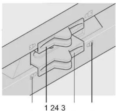
text_image
1 24 3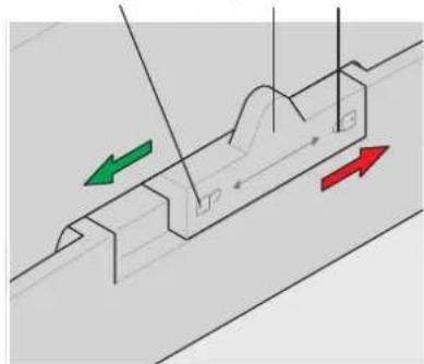
natural_image
Diagram of a mechanical or fluidic channel with directional arrows indicating flow or movement (no text or symbols present)Fig. 94 Refrigerator lock Dometic 7 series
1 Freezer compartment latch
2 Refrigerator latch
3 Lock the door
4 Unlock the door
Opening the refrigerator Dometic 7 series:
→ Slide latch (Fig. 94/1) or (Fig. 94/2) to the left (Fig. 94/4).
→ Open the refrigerator door.
Closing the refrigerator Dometic 7 series:
→ Close the refrigerator door.
→ Slide latch (Fig. 94/1) or (Fig. 94/2) to the right (Fig. 94/3). The refrigerator door is locked.
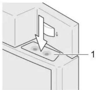
natural_image
Diagram of a door with a flag and arrow indicating direction, no text or symbols present1 Unlock button
Fig. 95 Refrigerator lock Dometic 8 series
Opening the refrigerator Dometic 8 series:
→ Press the unlock button (Fig. 95/1) down and open the refrigerator door.
Closing the refrigerator Dometic 8 series:
→ An automatic lock is fitted on the refrigerator door. When you close the refrigerator door and press it on firmly, the door locks automatically.
Locking Thetford refrigerators:
→ An automatic lock is fitted on the refrigerator door. When you close the refrigerator door and press it on firmly, the door locks automatically.
15.1.2 Dometic 7 series with automatic or manual mode selection system
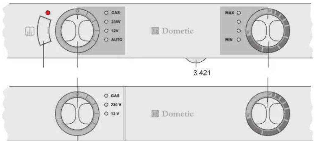
text_image
GAS 230V 12V AUTO Dometri MAX MIN 3 421 GAS 230 V 12 V DometriFig. 96 Refrigerator controls (Dometic 7 series)
1 Frame heater switch
2 On/Off / energy selector button
3 Dimmer for LED indicator (accessible only when the door is open)
4 Gas / electric thermostat
15.1.3 Dometic 8 series with manual mode selection and automatic ignition MES
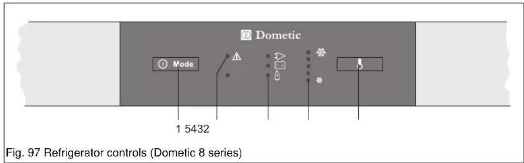
text_image
Dometic Mode 1 5432 Fig. 97 Refrigerator controls (Dometic 8 series)1 On/Off / energy selector button
2 "Malfunction" LED indicator
3 "Mode" LED indicator
4 "Temperature range" LED indicator
5 Temperature setting switch
15.1.4 Dometic 8 series with manual mode selection and battery ignition.
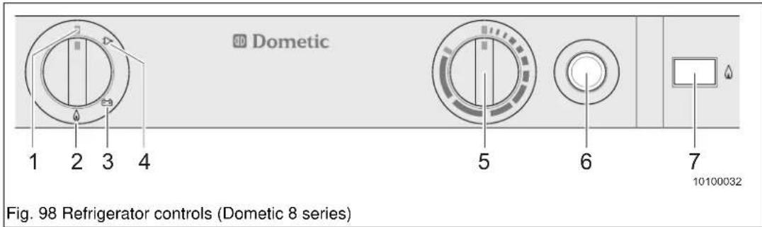
text_image
Dometic 1 2 3 4 5 6 7 10100032 Fig. 98 Refrigerator controls (Dometic 8 series)1 Power selector switch "Off"
2 Power selector switch "Gas mode"
3 Power selector switch "12 V"
4 Power selector switch "230 V"
5 Temperature controller
6 Battery ignition (gas mode)
7 Flame display (gas mode)
15.1.5 Thetford Premium LCD

text_image
THETFORD 2 34 5 1Fig. 99 Refrigerator and freezer compartment controls (Thetford Premium LCD)
1 Main switch
2 "Mode selector" switch
3 "Cooling capacity" selector switch
4 LCD display
5 "Mode" LED indicator
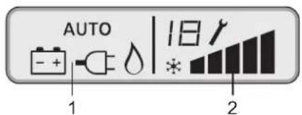
text_image
AUTO 1 18 * 2Fig. 100 LCD display
1 Mode
2 Cooling capacity / Fault / Service
For more information, see the separate manufacturer's operating instructions.
15.2 Placing into service
15.2.1 Frame heater
Water drops can occur on the metal frame during the summer with high temperatures and high air humidity. Some models have a frame heater for the freezer compartment to prevent this.

Caution!
Battery discharge
The frame heater continuously draws power from the 12 V DC supply. During 12 V mode using the starter battery (towing vehicle), observe the LED display when the motor is switched off and the vehicle parked. Switch off the frame heater.
Switching the frame heater on:
→ Switch on the frame heater with the switch (Fig. 96/1). The LED above the switch goes on when the frame heater is switched on.
15.2.2 12 V mode
The 12 V mode should be selected only while the engine is running.
However, we recommend operation with gas even when the engine is running because the high energy input of the refrigerator draws too much energy from the onboard batteries.
15.2.3 230 V mode
Select the 230 V mode only when an external 230 V supply is connected.
Before starting the journey, obtain information on the voltage in the country to be visited.
15.2.4 Gas mode
Danger!
Risk of explosion at petrol stations!
▲ Open flames are prohibited at petrol stations!
- Switch the refrigerator off using the power selector switch!
Caution!
Using gas
▲ Only use liquid gas to run the refrigerator (Chapter 11.3).
▲ Operating the refrigerator with gas during the journey is generally allowed.
Before starting the journey, obtain information concerning special provisions of the country to be visited (EN 732).
At altitudes of more than 1000 m above sea level, physical factors may cause problems with the ignition of the gas. This is not a malfunction!
▲ Operation using gas is prohibited in petrol stations!
Using the refrigerator with gas:
→ Open the shut-off valve of the gas cylinder and the quick-action stop valve (Fig. 69/3) on the distributor block.
→ Select mode "Gas" using the power selector switch.
On refrigerators with manual ignition, press the battery ignition (Fig. 98/6) until the flame display has moved to the green area.
→ On refrigerators with manual power selection (MES), press the power selector switch (Fig. 97/1) resp. (Fig. 99/2) so often until "Gas mode" is selected. Ignition is then automatic.
i Important!
On appliances with automatic power selection (AES or AUTO shown in the display), the priority sequence of the control electronics first selects GAS when neither of the electric power types are available.
For more information, see the separate instructions from the manufacturer.
15.2.5 Winter mode

Important!
Attach the winter covers also when the vehicle is taken out of service for an extended period of time or cleaned on the outside.
Check in winter operation:
→ Check regularly that the ventilation grilles have not been blocked by snow, ice, leaves or similar.
When the outside temperature drops below +8^ , the winter covers (special accessory) should be fitted to the ventilation grilles
This protects the refrigerator unit from excessively cold air.
For more information, see the separate instructions from the manufacturer.
15.3 Storing food
15.3.1 General information
- Switch the refrigerator on approx. 12 hours before storing food.
- Always store pre-cooled food only. When buying and transporting food, make sure the food is well pre-cooled. Use insulated bags for transport.
- Always open the refrigerator door just briefly.
• Always store the food separately and well packed (closed containers, aluminium foil, etc.). - Never put hot food into the refrigerator. Always let it cool first.
- Store sensitive food directly near the fins.
- Bear in mind that the temperature inside a closed vehicle can rise significantly as a result of sun irradiation. This can affect the performance of the refrigerator.
- Pay attention to the unhindered air circulation of the refrigerator unit.
15.3.2 Freezer compartment
- Do not store carbonated drinks in the freezer compartment.
- The freezer compartment is suitable for making ice cubes and for short-term storage of frozen food.
- The freezer compartment is not suitable for freezing food!
15.4 Putting out of operation

Important!
If the refrigerator is switched off for a longer period of time, the door should remain open somewhat. For this purpose, the lock has a special latching position.
For more information, see the separate instructions from the manufacturer.
16 Toilet

Caution!
Damage to the environment
▲ Use an environment-friendly and biodegradable chemical toilet additive for the toilet. - The ventilation will remove merely the odour but not germs and gases. Germs and gases can have a detrimental effect on the rubber seals.

Caution!
Material breakage
▲ Do not sit on the toilet lid. - The lid is not designed to bear the weight of a person and could break.

Important!
- Do not leave water in the bowl when the toilet is not used. This does not prevent unpleasant odours but could cause flooding. - Use quick dissolving toilet tissue in order not to affect the mechanical components of the cassette.
Whenever using the toilet:
→ Every time you place the Thetford Cassette into service, perform all preparations according to the separate manufacturer's operating instructions.
→ Before using the Thetford toilet for the first time, fill the water tank with fresh water (Chapter 12.1.1) or fill the separate water tank (only with Thetford toilet C-402 C, Chapter 16.1.2).
→ Cover the bottom of the cassette with water and fill in environment-friendly and biodegradable toilet chemicals. Observe the manufacturer's instructions for the dosage. For environmental reasons, the toilet can also be used without chemical additives, however, this requires more frequent emptying of the cassette (Chapter 16.2).
16.1 Toilet system
16.1.1 Thetford Cassette C-200 S and C-260 S

Fig. 101 Thetford C-200 S and C-260 S
1 Lever for opening the valve blade
2 Operator panel
3 Flush button
4 Waste level indicator
5 Automatic ventilator (special equipment)
Before use:
→ Turn the toilet bowl to the desired position using both hands.
→ Before flushing, use the lever (Fig. 101/1) to open the valve blade.
→ To activate the control panel, press the flush button (Fig. 101/3) once.
→ Run some water into the bowl by pressing the flush button again briefly.
After use:
→ Push the lever (Fig. 101/1) to the side if the valve blade is still closed.
→ Flush the toilet (Fig. 101/3) by pressing the flush button for several seconds (if necessary, reactivate the control panel (Fig. 101/2).
→ Close the valve blade with the lever (Fig. 101/1) after flushing.
For more information, see the separate instructions from the manufacturer.
16.1.2 Thetford Cassette C-402 C
The C-402 C toilet has an own water tank.
i Caution!
Damage to toilet and vehicle
▲ Do not leave water in the bowl when the toilet is not used. This can cause blockages.
▲ Do not fill the flushing water tank more than half full when travelling. Otherwise water damage could occur on your vehicle.
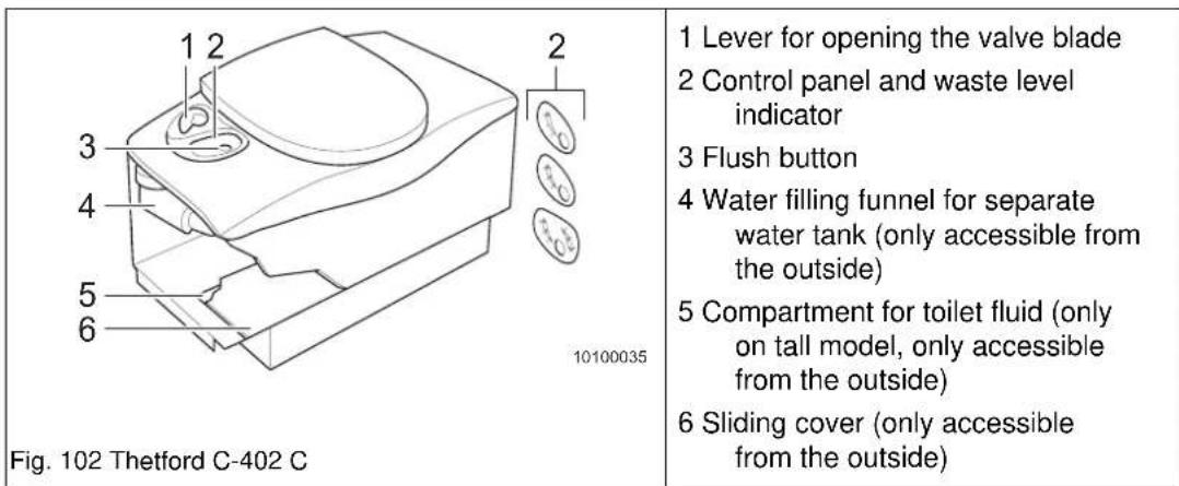
1 Lever for opening the valve blade
2 Control panel and waste level indicator
3 Flush button
4 Water filling funnel for separate water tank (only accessible from the outside)
5 Compartment for toilet fluid (only on tall model, only accessible from the outside)
6 Sliding cover (only accessible from the outside)
Before use:
→ Check that the water tank is filled with water.
→ Before flushing, use the lever (Fig. 102/1) to open the valve blade anticlockwise.
→ Press the flush button (Fig. 102/3) once to run some water into the bowl.
After use:
→ If the valve blade is still closed, use the lever (Fig. 102/1) to open the valve blade anti-clockwise.
→ Press the flush button (Fig. 102/3) for several seconds to flush.
→ Close the valve blade with the lever (Fig. 102/1) after flushing.
For more information, see the separate instructions from the manufacturer.
16.1.3 Water tank toilet C-402 C
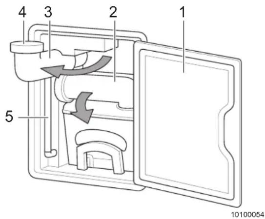
text_image
1 2 3 4 5 10100054Fig. 103 Water tank toilet C-402 C
1 Outer door
2 Cassette emptying spout
3 Water filling funnel
4 Water filling funnel cap
5 Water level indicator
The water tank holds 15 liters.
Filling the water tank:
→ Open the outer door (Fig. 103/1) for the cassette and water fill funnel.
→ Swivel the cassette emptying spout (Fig. 103/2) out about 90° and remove the water tank extension (Fig. 107/4).
→ Swivel the water filling funnel (Fig. 103/3) out about 90° and unscrew the cap (Fig. 103/4).
→ Position the water tank extension on the water filling funnel.
→ Observe the water level in the tube (Fig. 103/5) and fill with water up to just under the water filling funnel.
→ Remove the water tank extension.
→ Screw the cap (Fig. 103/4) back on and swivel the water filling funnel (Fig. 103/3) back in.
→ Store the water tank extension (Fig. 107/4) on the cassette and swivel the emptying spout of the cassette (Fig. 103/2) back in.
→ Close the outer door (Fig. 103/1).
For more information, see the separate instructions from the manufacturer.
16.1.4 Thetford Cassette C-403 L
i Caution!
▲ Do not leave water in the bowl when the toilet is not used. This can cause blockages.
| Fig. 104 Thetford C-403 L | 1 Lever for opening the valve blade 2 Control panel and waste level indicator 3 Flush button 4 Compartment for toilet fluid (only on tall model, only accessible from the outside) 5 Sliding cover (only accessible from the outside) |
Before use:
→ Before flushing, use the lever (Fig. 104/1) to open the valve blade anticlockwise.
→ Press the flush button (Fig. 104/3) once to run some water into the bowl.
After use:
→ If the valve blade is still closed, use the lever (Fig. 104/1) to open the valve blade anticlockwise.
→ Press the flush button (Fig. 104/3) for several seconds to flush.
→ Close the valve blade with the lever (Fig. 104/1) after flushing.
For more information, see the separate instructions from the manufacturer.
16.2 Cassette

Caution!
Danger for the environment
▲ Use an environment-friendly and biodegradable chemical toilet additive for the toilet.
▲ The cassette may be emptied only at camping sites with suitable waste water treatment plants or special waste disposal stations (e.g. at parking sites for camping vehicles).

Caution!
Damage to the water pump during winter operation
In winter operation, the toilet may be flushed only after the toilet compartment has been well heated, otherwise the water pump of the flush system could be damaged.
▲ Do not use antifreeze.

Important!
- Never add toilet fluid through the valve blade or the toilet bowl.
- In the cassette, the liquids are immediately mixed with water and closed in. This prevents unpleasant odours in the bathroom.
16.2.1 Thetford Cassette C-200 S
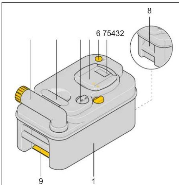
text_image
6 75432 8 9 1Fig. 105 Thetford Cassette C-200 S
1 Cassette
2 Swivelling emptying spout
3 Upper carrying handle
4 Automatic holding tank vent valve
5 Sliding cover
6 Vent plunger
7 Valve blade
8 Hand grip
9 Catch
The cassette (Fig. 105/1) has a capacity of approx. 17 l and should be emptied when the level indicator (Fig. 101/4) lights. Do not allow the cassette to become overfilled.
16.2.2 Thetford Cassette C-260 S
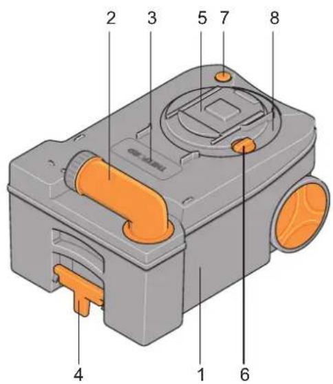
text_image
2 3 5 7 8 4 1 6Fig. 106 Thetford Cassette C-260 S
1 Cassette
2 Swivelling emptying spout
3 Automatic holding tank vent valve
4 Pull-out hand grip / latch
5 Sliding cover
6 Valve blade
7 Vent plunger
8 Removable mechanism
The cassette (Fig. 106/1) has a capacity of 18 l and should be emptied when the level indicator (Fig. 101/4) lights. Do not allow the cassette to become overfilled.
16.2.3 Thetford Cassette C-402 C and C-403 L
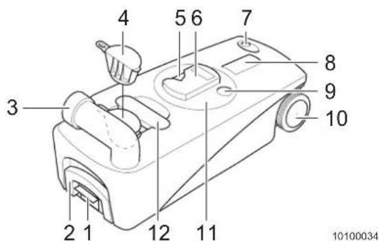
text_image
4 5 6 7 8 3 9 10 2 1 12 11 10100034Fig. 107 Thetford Cassette C402 C and C403 L
1 Catch
2 Hand grip, fold-out
3 Swivelling emptying spout
4 Water tank extension (C-402 C)
5 Valve blade
6 Sliding cover
7 Vent plunger
8 Automatic holding tank vent valve
9 Valve blade opener
10 Wheels
11 Removable mechanism
12 Upper carrying handle
The cassette has a capacity of approx. 19 l and should be emptied when the level indicator (Fig. 102/2) or (Fig. 104/2) lights. Do not allow the cassette to become overfilled.
16.2.4 Emptying the cassette
Removing the cassette:
→ Close the valve blade (Fig. 101/1), (Fig. 102/1), (Fig. 104/1) in the toilet.
→ Open the outer access door.
→ Release the cassette with the catch (Fig. 105/9), (Fig. 106/4) or (Fig. 107/1) and remove.
→ When the cassette is pulled out, the valve blade (Fig. 105/7), (Fig. 106/6) or (Fig. 107/5) is hygienically closed by the sliding cover (Fig. 105/5), (Fig. 106/5) or (Fig. 107/6).
Emptying the cassette at disposal stations:
→ For C-260S, C-402 C and C-403 L: Pull the hand grip (Fig. 106/4) or (Fig. 107/2) upwards and take the cassette to the approved waste disposal station.
→ Place the cassette upright. The emptying spout (Fig. 105/2), (Fig. 106/2) or (Fig. 107/3) must be at the top.
→ Turn the emptying spout (Fig. 105/2), (Fig. 106/2) or (Fig. 107/3) upwards.
→ Unscrew the cap from the emptying spout.
→ C-200S: Lift the cassette with one hand on the upper carrying handle (Fig. 105/3); with the other hand on the hand grip (Fig. 105/8).
→ Turn the cassette so that it is emptied.
→ Press the vent plunger (Fig. 105/6), (Fig. 106/7) or (Fig. 107/7) with a thumb.
Press the vent plunger only when the emptying spout is pointed downwards. Pressing the vent plunger empties the tank without splashing.
→ Thoroughly rinse the cassette with water.
→ Also clean the valve blade with water.
→ Then pour toilet fluid into the cassette.
The cap of the emptying spout has a measuring cup on the inside.
This decomposes the faeces quickly, prevents unpleasant smells in the cassette and keeps the inside of the tank clean.
→ Fit the tank back in again.
→ Close the access door.
For more information, see the separate instructions from the manufacturer.
16.3 Placing the toilet out of service
i Important!
Empty the cassette and water tank when the vehicle is not heated and there is a risk of frost.
Placing the toilet out of service:
→ Place a sufficiently large container underneath the drain plug of the water tank.
→ Open the drain plug, drain the water tank completely and allow to dry.
→ Empty the cassette (Chapter 16.2).
→ Leave the emptying spout open to allow the tank to dry.
→ Clean the toilet (Chapter 19.2.6).
→ Clean all seals and treat with care products for seals.
For more information, see the separate instructions from the manufacturer.
16.4 Preparing the toilet for winter mode
Caution!
Damage to the water pump during winter operation
In winter operation, the toilet may be flushed only after the toilet compartment has been well heated, otherwise the water pump of the flush system could be damaged.
▲ Do not use antifreeze.
i Important!
- Empty the cassette and water tank when the vehicle is not heated and there is a risk of frost.
For more information, see the separate instructions from the manufacturer.
17 Winter camping
17.1 Travelling in winter
Winter camping is becoming more and more popular. Depending on the model and equipment, your ADRIA vehicle is conditionally suitable for use in winter. If you pay attention to the following information, your winter holiday in your own vehicle will become proper winter fun.
i Important!
Before starting the journey, mount suitable winter tyres and have snow chains on board. Snow chains are prohibited on aluminium rims.
When camping in winter:
→ Obtain exact information about road conditions and weather.
→ Avoid roads with strong uphill/downhill gradients.
→ Select the camping site carefully and in time, plan your arrival during the day.
→ Carefully check the tyres, tread depth and tyre pressure (Tab. 26).
→ Fill the windscreen washer unit with frostproof cleaner, take reserve frostproof cleaner for the journey with you.
→ Before starting the journey, clear snow and ice from the roof, all windows, mirrors and lights as well as the wheel wells.
→ Do not warm up the engine while parked, smoothly drive off immediately after you start the engine.
→ Use only propane gas (Chapter 11.3.1) with a two-cylinder system for winter camping.
→ Allow for sufficient gas supplies.
Pitching the caravan:
→ Clear the snow from the parking area before pitching the vehicle.
→ Do not park the vehicle underneath trees. Falling branches or pieces of ice can damage the roof and roof hoods.
→ Check the underground regularly to prevent sinking in when thawing sets in.
→ After pitching, secure the vehicle with wheel chocks against rolling away. Release the parking brake to prevent freezing.
→ After travelling on salt-covered roads, the complete vehicle including the chassis has to be thoroughly washed with water.
→ To prevent white rust formation of the galvanised parts, ensure adequate air circulation underneath the vehicle. Water must be capable of flowing off.
→ Lay the 230 V power cable so as to prevent it freezing to the ground or being damaged when snow is cleared.
17.2 Winter operation

Danger!
Risk of suffocation
▲ Do not use any catalytic stoves or infrared radiators in the vehicle. The oxygen in the living area is then used.

Caution!
Risk of damage through freezing
▲ Do not store any fluids in the unheated vehicle when there is a risk of frost.
If the vehicle is left with the heating switched off for a longer period of time at low temperatures, the water pipes and tanks could freeze and thus be damaged.
▲ Empty the waste water tank when there is a risk of frost and the heating is switched off.
When there is a risk of frost and the vehicle is not heated, the waste water system must be carefully cleaned, thoroughly rinsed, completely emptied and thoroughly dried.
When there is a risk of frost, water taps have to be left open in the unheated vehicle even when the water supply is drained. Drain the faucets that have a "warm" and a "cold" position in both positions and leave them open in one of the positions.(Chapter 12.2).
The vehicle is insulated and to a large extent suitable for use in winter when operated properly. The water supply is located inside the vehicle.
The snow and ice load can amount to several hundred kilograms and so reduce the additional load of your vehicle.
In winter, temperature differences and wet objects (e.g. ski clothes) in the vehicle increase condensation.
Warm air absorbs much more humidity than cold air. When the warm air in the vehicle cools down, water condenses in cold places (windows, window frames and storage compartments). This can be remedied by adequate heating with the air circulation switched on.
When camping in winter:
→ Vent openings may not be covered by snow or snow drifts. Clear the snow also from underneath the vehicle so that the heater receives enough fresh air.
→ Clear snow and ice off the roof and awning at regular intervals (Chapter 2.8).
→ Always keep the heater exhaust clear. Attach cowl extensions (special accessory).
→ Provide for good ventilation (air circulation) and heating. Always keep the forced ventilation open.
→ Use the awning as a wind guard and storage area for wet objects, e.g. skiing equipment.
→ Always open all cabinet doors, flaps and storage compartments when heating the vehicle to prevent condensation.
→ Wipe off any condensation.
→ Air and dry the cushions daily.
→ Open windows and roof hoods when cooking.
→ If possible, do not use electrical appliances with high current consumption. The current capacity at camping sites is limited.
→ Make sure the drain pipe of the waste water does not freeze up (Chapter 12.2).
17.3 Checklist for winter camping
| Checklist for winter camping | √ |
| Snow chains (prohibited for aluminium rims!) | |
| Thermal mat (to lay on), work gloves | |
| Sandbag, small shovel | |
| Snow shovel, grit | |
| Broom | |
| Anti-skid mats | |
| Talc, Vaseline for rubber seal | |
| Door lock and window de-icer | |
| Battery jumper cable | |
| Plastic windshield scraper | |
| Fill the windscreen washer unit with frostproof cleaner (do not forget reserve frost-proof cleaner for the journey) | |
| Anti-mist cloth for windscreen | |
| Wheel chocks | |
| Antifreeze for the waste water tank (e.g. table salt) | |
| Torch / flashing hazard warning light (use new batteries) | |
| Winter cover for refrigerator grille (special accessory) | |
| Exhaust gas cowl extension (special accessory) | |
Tab. 11 Checklist for winter camping
18 Placing out of service
i Important!
When the instructions for maintenance and care, and the checklist for placing out of service are observed, the vehicle can be parked outdoors all year round.
18.1 Checklist for temporary placing out of service:
| Activity | √ | |
| Bodywork Keep | the forced ventilation and all mushroom ventilators open. | |
| Carefully wash the vehicle and apply a paint protection product (wax). | ||
| Repair paintwork damage. Your ADRIA dealer will be pleased to advise you with respect to suitable products. | ||
| Move the vehicle every four weeks in order to avoid "flat spots" and damage to the wheel bearings. Secure the vehicle with wheel chocks from rolling away. | ||
| Regularly check the tyre pressure. | ||
| Disengage the parking brake. | ||
| Protect the tyres from direct exposure to the sun. | ||
| Thoroughly air the vehicle every 4 weeks. | ||
| If the vehicle is to be parked in an enclosed area, at least two windows must remain open. | ||
| Provide for good ventilation in the underbody area. | ||
| Cover the exhaust cowl, if possible | ||
| If the vehicle is covered with a tarpaulin, make sure air can still circulate above the roof. The tarpaulin must not rest directly on the roof to prevent it from sticking to the roof. Light wooden slats allow for air circulation on the roof. | ||
| Gas system C | ose the gas shut-off valve of the gas cylinder. | |
| Close all quick-action stop valves for all appliances. | ||
| Always remove all gas cylinders from the gas cylinder compartment and store them safely. | ||
| Close the open end of the gas hose so that no dirt or insects can enter. | ||
| Water sys-tem | Empty the entire water system completely, clean carefully and allow to dry. | |
| Leave all water taps, all drain cocks as well as all drain valves open. Drain the faucets that have a "warm" and a "cold" position in both positions and leave them open in one of the positions. | ||
| Bacteria and algae can form in the water tank, therefore, after the end of the journey, the water tank must always be drained, thoroughly cleaned (Chapter 12.2) and allowed to dry.We recommend using a disinfectant for the water tank. Ask your ADRIA dealer for advice. | ||
| Appliances Empty and clean the refrigerator; leave the refrigerator door and the freezer compartment, if applicable, open. | ||
| For information concerning the temporary placing out of service of the appliances, see the separate appliance operating instructions. | ||
| Living area Leave all cabinet doors, access doors, storage compartments, seat chests and bed boxes open. | ||
| Clean the living area and storage compartments. | ||
| Stand all the cushions up for ventilation or store them in the house. | ||
| Make sure that the forced ventilation is open and not covered. | ||
Tab. 12 Checklist for temporary placing the vehicle out of service
18.2 Placing out of service over the winter
The following measures are required in addition to those already mentioned for the temporary placing out of service over the winter.
| Activity | √ | |
| Bodywork Clear snow from the roof when it snows. | ||
| Thoroughly heat and ventilate the vehicle every four weeks. | ||
| Lubricate all hinges and locks. | ||
| Apply talc or Vaseline to all rubber seals. | ||
| Use graphite dust to treat locking cylinders. | ||
| Install the winter cover for the refrigerator grille (special accessory). | ||
| Appliances For information concerning the placing out of service of the appli-ances over winter, see the separate appliance operating instructions. | ||
| Living area Make sure the forced ventilation is open and not covered. | ||
| Keep all cushions dry in the house. | ||
| Position dehumidifiers and check them regularly. | ||
Tab. 13 Checklist for placing out of service over the winter
18.3 Returning to service after the placing out of service
Perform the following activities for returning the vehicle to service.
| Activity | √ | |
| Bodywork Remove tarpaulin and possibly wooden slats. | ||
| If the vehicle has been stationary for a long period (approx. 10 months), have the brake system checked by an authorised work-shop. | ||
| Check the tyre pressure, also of the spare wheel (special equipment). | ||
| Remove cover from the exhaust cowl, if present. | ||
| Remove the winter cover for the refrigerator grille (special accessory). | ||
| Check the function of all doors, windows, flaps and hatches. | ||
| Check the function of all external locks (e.g. entrance door, filler neck, flaps, etc.). | ||
| Gas system Lash the gas cylinders in the gas cylinder compartment and connect gas cylinders. | ||
| If the vehicle has been stationary for a long period (approx. 10 months), have the gas system checked by an authorised work-shop. | ||
| Electrical system | Check the function of the electrical system (e.g. lighting, sockets) and of all appliances (e.g. refrigerator). | |
| Check the function of the ground-fault circuit breaker. | ||
| Water sys-tem | Thoroughly rinse the complete water system with plenty of fresh water; leave the taps open. | |
| Close all water taps and drain valves. | ||
| Check for leakage and function of all water taps and drain valves. | ||
| Appliances For information concerning the returning to service of the appliances, see the separate appliance operating instructions. | ||
| Check the function of all appliances (e.g. refrigerator, cooker, heater, etc.). | ||
| Living area Replace all cushions. | ||
| Remove dehumidifiers. | ||
Tab. 14 Checklist for returning to service
19 Cleaning & care
19.1 Cleaning and care - exterior
The polyester outer skin (glass-fibre reinforced plastic) of the vehicle was dyed at the factory, i.e. not painted. We recommend the following steps for the care of the vehicle:

Warning!
Risk of injury and damage to the vehicle roof
▲ The roof of the vehicle is not designed for the weight of standing persons.
▲ The roof of the vehicle is not capable of supporting walking persons.
▲ Do not walk on roof structures or roof fittings, e.g. roof hoods, roof railings etc.

Important!
- Never drive the vehicle through a wash facility. The acrylic glass windows will be scratched by the rotating cleaning brushes.
- When cleaning the vehicle with a high-pressure cleaner, maintain a distance of approx. 70 cm from the nozzle to the vehicle surface.
- Never point the water jet directly towards doors, windows, flaps and vent openings. Splashing water can penetrate the vehicle through the circumferential air gap between the glass dome and the frame (forced ventilation).
- Do not spray directly on deco foils as they could become detached.
- Never point the water jet directly towards electric accessories and plug connections.
- Do not use glass cleaners, abrasives, solvents, cleaning agent containing methylated spirit or alcohol. This would result in cracks or embrittlement of the acrylic material.
- Avoid everything that could cause scratching or scoring.
- Avoid torsional forces when opening and closing the windows.
→ Wash the vehicle with plenty of cold to lukewarm water and cleaning agent. Then dry thoroughly.
→ You can purchase suitable cleaning agents and additives from your ADRIA dealer.
→ Bird droppings, tree gum, berries, road salt, sea salt, etc. must always be removed immediately.
→ Clean windows only with plenty of lukewarm water and mild soap solution.
→ Treat rubber seals on doors, windows and flaps with talc or Vaseline.
→ Check the condition of the undersealant once a year. If the undersealant is defective, contact your ADRIA dealer.
→ The chassis is galvanised. Seal areas where rust is setting in (e.g. caused by stone-chipping or other effects) by the application of cold zinc.
→ After driving in winter on salt-covered roads, thoroughly clean the galvanised surfaces and aluminium components and rinse with clear water.
To prevent the formation of white rust (only a visual defect) on the galvanised parts, ensure adequate air circulation underneath the vehicle. Water must be capable of flowing off.
→ When staying near the sea, regularly wash the vehicle with clear fresh water.
→ The painted outer surface of the vehicle can be preserved with a commercially available wax. Pay attention to the manufacturer's instructions.
→ Treat polyester parts every year with a two-component wax. Pay attention to the manufacturer's instructions.
→ Observe the environmental protection measures in cleaning and care of the vehicle.
19.1.1 Cleaning the acrylic windows (side windows, roof hoods)
i
Important!
- Never drive the vehicle through a wash facility. The acrylic glass windows will be scratched by the rotating cleaning brushes.
- When cleaning the vehicle with a high-pressure cleaner, maintain a distance of approx. 70 cm from the nozzle to the vehicle surface.
- Never point the water jet directly towards doors, windows, flaps and vent openings. Splashing water can penetrate the vehicle through the circumferential air gap between the glass dome and the frame (forced ventilation).
- Do not use glass cleaners, abrasives, solvents, cleaning agent containing methylated spirit or alcohol. This would result in cracks or embrittlement of the acrylic material.
- Avoid everything that could cause scratching or scoring.
- Avoid torsional forces when opening and closing the windows.
i
Important!
Condensation water can form between the double windows of the acrylic glass window. The condensation water disappears by itself, however, this takes some time.
Acrylic glass windows are very delicate and require very careful handling. Non-compliance with the cleaning instructions voids the manufacturer's warranty.
→ Clean the windows with only warm water and a soft, clean sponge or cloth.
→ If the windows are very dirty, use a solution with water and mild soap solution to keep the windows clear and free from electrostatic charging.
→ For stubborn soiling, we recommend a special cleaning agent for acrylic glass which is available from your ADRIA dealer.
→ Do not use scouring agents. They would scratch the plastic surfaces.
→ After cleaning the vehicle, rinse all acrylic glass windows with clean water.
→ Treat rubber seals with talc.
→ Regularly lubricate all moving parts, hinges and flaps with acid-free grease (e.g. Ballistol).
→ Do not allow water to penetrate the mechanical parts.
→ The insect screens and blinds can be cleaned with a soft brush. If the insect screens and blinds are very dirty, use water and mild soap solution to wash them. Then allow the screens and the blinds to dry well.
19.1.2 Cleaning plastic parts
→ Clean plastic parts only with warm water, mild household cleanser and a soft, clean sponge or cloth. The aqueous solution should contain 2% cleaning agent at the most.
→ Do not use scouring agents. They would scratch the plastic surfaces.
→ Very greasy or oily spots can be washed with ethyl, isopropyl or isobutyl alcohol. Organic solvents (e.g. acetone, methanol or ethanol) could damage the material.
→ An example of possible damage to moulded plastic parts are stress cracks caused by different media. Other chemicals can have a swelling and softening effect on the plastic material. Therefore, plastic parts should be subjected to contact with the solvents referred to above only for a short period (2 minutes max.) at room temperature.
→ Avoid mechanical loads (e.g. clamping, twisting) of the plastic parts during cleaning in order to prevent distortion.
19.2 Cleaning and care - interior
i Important!
Exposure to sunlight can cause the plastic parts to yellow. This is not a quality defect.
i Important!
- Use only commercially available, mild cleaning agent to clean the vehicle. Ask your ADRIA dealer for advice.
- Do not use caustic or abrasive cleaning agent.
- Avoid everything that could cause scratching or scoring.
19.2.1 Cleaning plastic parts
! Warning!
Risk of injuries through caustic substances
▲ Do not get acids into the eyes or on mucous membranes! Avoid skin contact!
▲ To remove calcification, use only highly diluted, commercially available acids (e.g. acetic acid).
→ Clean plastic parts only with warm water, mild household cleanser and a soft, clean sponge or cloth. The aqueous solution should contain 2% cleaning agent at the most.
→ Do not use scouring agents. They would scratch the plastic surfaces.
→ Very greasy or oily spots can be washed with ethyl, isopropyl or isobutyl alcohol. Organic solvents (e.g. acetone, methanol or ethanol) could damage the material.
→ An example of possible damage to moulded plastic parts are stress cracks caused by different media. Other chemicals can have a swelling and softening effect on the plastic material. Therefore, plastic parts should be subjected to contact with the solvents referred to above only for a short period (2 minutes max.) at room temperature.
→ Avoid mechanical loads (e.g. clamping, twisting) of the plastic parts during cleaning in order to prevent distortion.
To prevent calcification, the water used must be softened. When calcification of the surface occurred, it can be removed with a diluted acid solution (e.g. acetic acid).
19.2.2 Care of furniture
→ Clean the furniture with a soft cloth and a commercially available furniture polish, do not use intensive cleansers.
→ Wash the work surfaces with water by adding a mild detergent or household cleanser.
→ Clean textile storage spaces and textile cabinets with cleansing foam.
19.2.3 Care of cushions, curtains, net curtains
→ Small spots in the cushions can be removed with commercially available cleaning foam for use on cushions or the foam of mild detergent.
→ Do not wash cushions.
→ Protect cushions from direct sunlight so that it does not fade.
→ Have large spots or soiling removed by the dry cleaners.
→ Have curtains and net curtains cleaned by the dry cleaners only.
→ Brush insect screens and Roman shades with a soft brush or vacuum with the brush attachment of the vacuum cleaner.
→ Grease spots on Roman shades can be removed with mild, warm laundry soap.
19.2.4 Care of PVC floor coverings and carpets (special equipment)

Caution!
Risk of damage
▲ Do not place the carpet on the wet PVC floor covering, the carpet and PVC floor covering may stick together and could tear the PVC floor covering off when the carpet is removed again.
▲ It is also possible that mould will form between the PVC floor covering and the carpet.
→ Wash the PVC floor covering with a commercially available cleanser and allow to dry well. Do not use wax.
→ Do not use scouring agents or aggressive cleansers.
→ Vacuum clean the carpet.
→ Clean spots with carpet foam.
19.2.5 Cleaning the kitchen
19.2.5.1 Cleaning work surfaces and sink
→ Wash the work surfaces with water to which a mild detergent or household cleanser has been added and dry the surfaces.
→ Clean the stainless steel sink with a commercially available cleanser.
19.2.5.2 Cleaning the gas stove

Caution!
Damage to gas stove
▲ Prevent water or cleaning agent from penetrating the gas outlet openings. Water may damage the gas stove.
▲ Do not use scouring agents. These scratch the surfaces.
→ Allow the gas stove to cool before cleaning.
→ Clean the gas stove only with a moist cloth.
→ Clean the glass cover (special equipment) of the cooker with a glass cleaning agent.
19.2.5.3 Cleaning the oven
Caution!
Damage to seals and surfaces
▲ Do not allow the door seal to come into contact with oil or grease.
▲ Do not use scouring agents. These scratch the surfaces.
→ Clean the inside and outside of the appliance before you place it into service and then at regular intervals.
→ Use only soft cloths. Clean the appliance only with mild household cleaners.
→ Then rinse the appliance with fresh water and dry thoroughly.
19.2.5.4 Cleaning the refrigerator
Caution!
Damage to seals and surfaces
▲ Do not use soap, abrasive or soda-based cleaning agent.
▲ Do not allow the door seal to come into contact with oil or grease.
▲ Do not use scouring agents. These scratch the surfaces.
→ Clean the inside and outside of the appliance before you place it into service and then at regular intervals.
→ Use only soft cloths. Clean the appliance only with mild household cleaners.
→ Then rinse the appliance with fresh water and dry thoroughly.
→ Remove dust from the refrigerator unit at yearly intervals using a brush or soft cloth. The refrigerator unit is accessible through the upper refrigerator grille.
19.2.6 Cleaning the bathroom

Caution!
Damage to surfaces
▲ Do not clean the bathroom and the toilet with solvents or cleaning agent containing alcohol. Do not use scouring agents.
– These could cause cracks or embrittlement of the plastic material.
▲ Do not pour caustic substances or boiling water into the drains.
– These damage both the drain pipes and the siphon traps.
▲ Do not allow the door seal to come into contact with oil or grease.
▲ Do not use scouring agents. These scratch the surfaces.
▲ Do not use vinegar essence for decalcifying the toilet and the water system. Use only commercially available mild decalcifying products that do not affect the plastic material.
- Ask your ADRIA dealer for advice.
→ Clean the bathroom and the toilet only with warm water, a soft cloth or sponge and mild, standard cleaning agent.
→ Clean the toilet compartment only with a moist cloth and mild cleaning agent.
→ The seals of the cassette, the vents and the lid as well as the valve blades of the toilet must be cleaned regularly with a mild cleaning agent for plastic materials.
19.2.7 Cleaning the water tank, waste water tank and toilet water tank
→ Always clean the water tanks and water pipes every time before filling them with commercially available cleaning agent and rinse them with plenty of water.
Before you put the vehicle out of service, the water tanks must be carefully cleaned, thoroughly rinsed, completely emptied and thoroughly dried (Chapter 12.3).
20 Inspection & Maintenance
20.1 Inspection work
i Important!
As with any vehicle, the caravan must be officially inspected at regular intervals (Chapter 2.4).
i Important!
Use only original spare parts from the respective manufacturer.
→ Inspection and maintenance work (Chapters 20.3 and 20.4) must be performed at regular intervals.
→ Since special technical knowledge is required for the performance of the maintenance and inspection work, it has to be performed by authorised workshops.
→ Regular maintenance guarantees value retention of the vehicle.
20.2 Brakes
Warning!
Risk of injury and severe damage to the vehicle
▲ Check brake system at regular intervals.
▲ All repairs and adjustments of the brake system have to be performed in an authorised workshop only!
The wear of the brake lining depends on the driving technique.
→ Consult an authorised workshop immediately if the braking behaviour is not normal (pulling to one side or reduction in braking pressure).
→ Drive with consideration and foresight.
→ Avoid braking abruptly.
→ Have the brake system inspected at regular intervals.
20.3 Chassis
| Maintenance activity Interval | |
| General inspection of caravan According to regulations in | the country of registration |
| Have the brake system checked in an authorised workshop Every year | |
| Have the undersealant checked Every year | |
| Check the tightening torque of wheel nuts Monthly | |
| Check tread depth and tyre pressure Before starting to drive | |
| Check the exterior lighting Before starting to drive |
Tab. 15 Chassis maintenance and inspection plan
On vehicles that are not driven much, the maintenance work must be performed every year and in time before the start of the journey.
20.4 Bodywork
| Maintenance activity Interval | |
| Delivery check Before delivery | |
| Replace the gas regulator and gas hose Every 10 years | |
| Official gas inspection | Every 2 years |
| leakage test | According to warranty conditions |
| Bodywork inspection | Every year |
| Have the electrical system checked | Every year |
| Have the gas system checked | Every year |
| Check screw connections of fixing clamps of roof hoods | Every year |
| Rub talc on seals on doors, windows and roof hoods | Every year |
| Clean the moving parts of the entrance step (special equipment) and the corner steadies (special equipment) and lubricate with grease | Half-yearly |
| Check water pipes and fittings for leaks and correct attachment | Half-yearly |
| Check charged condition of living area battery | Monthly |
Tab. 16 Bodywork maintenance and inspection plan
20.5 Checking and replenishing operating fluids
Operating fluids include:
• Air-conditioning system cooling medium (special equipment)
- Heater liquid for warm water heating (special equipment)
Please see the manufacturer's original operating instructions for checking operating fluids.
20.5.1 Checking and replenishing the fluid level of the Alde warm water heater
i Important!
- Avoid bubbles.
• Always position the vehicle horizontal and level.
The expansion tank of the Alde warm water heating is normally fitted in the wardrobe.
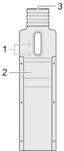
text_image
1 2 3Fig. 108 Checking the Alde water level
1 Water level markings
2 Protective cover
3 Lid with pump (behind cover)
Checking the water level:
→ Switch the Alde warm water heating off using the control panel.
→ Let the water cool down.
→ Check the water level is between the two markings (Fig. 108/1).
Topping up water:
→ Remove the protective cover (Fig. 108/2).
→ Unscrew the lid (Fig. 108/3) and remove the lid with circulation pump slowly upwards.
→ Check the antifreeze content. Antifreeze must be 40% or -25°C.
→ Fill water with antifreeze without bubbles to about 1 cm above the minimum marking.
21 Troubleshooting
Please pay attention to the following information for finding and correcting faults.
If you cannot remedy the faults yourself, contact the service of your competent ADRIA dealer or of the respective appliance manufacturer (heater = Truma, toilet = Thetford, etc.).

Warning!
Risk of injury and severe damage to the vehicle
▲ All repairs on the vehicle and on the brake system have to be performed in an authorised workshop only!
21.1 Changing wheels
21.1.1 Securing the vehicle
→ Wear a warning vest (different regulations from country to country).
→ If possible, remove the vehicle from the flowing traffic.
→ Secure the vehicle with a warning triangle and possibly a warning light.
→ Apply the handbrake.
→ Secure the vehicle with wheel chocks from rolling away.
21.1.2 Vehicles with tyre mobility system (special equipment)

Warning!
Health hazard
▲ Do not breathe in the vapours during repair. The spray can contains ethylene glycol and should not be used by asthmatics.
▲ Avoid contact with your eyes, skin and clothes. Immediately rinse off with plenty of water.
▲ Immediately consult a doctor if an allergic reaction occurs.

Important!
- With the tyre mobility system, tyres can be repaired whose treads were pierced by foreign objects with a diameter of 4mm max.
- The tyre mobility system is approved only for filling the tyres of a vehicle that was equipped by the factory with this tyre mobility system.
- Repaired tyres may be used only for a short period!
- Repair with the tyre mobility system is only a temporary measure!
The tyre mobility system can be found in the front part of the vehicle.
The scope of delivery includes:
- Spray can with sealing fluid
- Folded sheet with instructions
- Compressor with manometer and connecting pieces
- Adapter for pumping up various elements
Before repair:
Do not pull out any foreign objects (screws or nails) that have penetrated the tyre.
→ Before repair, carefully check the tyre sidewall.
Do not use the tyre mobility system when the tyre has already been damaged by driving with the flat tyre.
→ Also check the rim.
When the rim is damaged (deformation of the bead of the rim that causes loss of air), repair is not possible.
After repair:
→ Stop after driving for approx. 10 minutes and check the tyre pressure.
→ Consult a tyre repairman as soon as possible.
→ Inform the tyre repairman that the tyre has been repaired with the tyre mobility system.
→ Give the instruction sheet to the persons who have to repair the tyre that was treated with the tyre mobility system.
For more information concerning the tyre mobility system, see the separate manufacturer's operating instructions.
21.1.3 Vehicles with spare wheel (special equipment)
21.1.3.1 Vehicle jack (special accessory)

Danger!
Severe injuries by crushing
▲ Use only a vehicle jack with adequate lifting capacity. Determine the lifting capacity necessary in the technical data of your vehicle based on the gross weight rating.
▲ Never position the vehicle jack under the bodywork, always position the vehicle jack at the planned positions (under the axle or chassis).
▲ The vehicle jack serves only for wheel change. Never use it for working underneath the vehicle.
▲ Jack up the vehicle only on level and firm ground.
▲ Do not lie underneath the jacked up vehicle.
▲ Do not use the corner steadies for lifting the vehicle.
We recommend a caravan jack available as an accessory for changing wheels.
The ratchet wrench to loosen and tighten wheel bolts is located in the coupling bracket box.
For more information concerning the vehicle jack, see the separate manufacturer's operating instructions.
21.1.3.2 Changing the wheel

Warning!
Risk of injury when the vehicle rolls away
▲ Perform the wheel change only when the vehicle has been secured.

Caution!
Unsafe wheel attachment
▲ Always use the correct wheel bolts.
▲ For light-metal rims, different wheel bolts (diameter, length) can be used than for steel rims. Ensure the bolts are not interchanged.
→ Secure the vehicle (Chapter 21.1.1).
→ Uncouple the caravan and apply the handbrake.
→ Place the wheel chocks before and behind the opposite wheel. Position the jockey wheel at 90° to the driving direction and secure with cho cks behind and in front of the wheel. This secures the vehicle from rolling away.
→ Get the spare wheel and the tools.
→ Remove the protective caps from the wheel nuts or the wheel cover.
→ Unscrew the wheel nuts or wheel bolts by half a revolution with the wheel spanner.
→ Position the vehicle jack and jack up the vehicle until the defective wheel is off the ground (Chapter 21.1.3.1).
→ For safety, crank the corner steadies down to the ground without load. Do not use the corner steadies for lifting the vehicle!
→ Screw out the wheel nuts or wheel bolts and place them onto a clean surface. Make sure the threads are clean.
→ Change the wheel.
→ Clean the threads, turn in the wheel nuts or bolts and tighten by hand.
→ Stow the defective wheel in the spare wheel support.
→ Lower the vehicle and remove the vehicle jack.
→ Tighten the wheel nuts crosswise (Chapter 21.1.4).
→ Stow the tools and the safety equipment.
→ Check the tyre pressure at the next opportunity.
→ After driving approx. 50 km, check the seating of the wheel nuts or bolts and tighten.
21.1.4 Tightening the wheel nuts
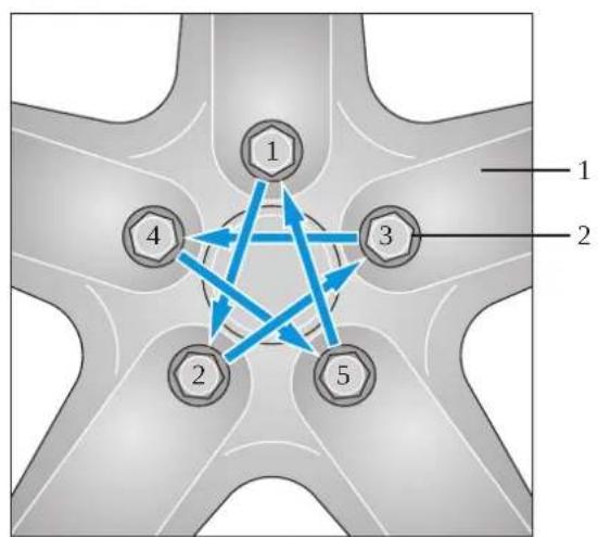
flowchart
graph TD
    A["1"] --> B["2"]
    B --> C["3"]
    C --> D["4"]
    D --> E["5"]
    E --> A
    style A fill:#f9f,stroke:#333
    style B fill:#bbf,stroke:#333
    style C fill:#bfb,stroke:#333
    style D fill:#ffb,stroke:#333
    style E fill:#fbb,stroke:#333
Fig. 109 Tightening the wheel nuts
1 Rim
2 Wheel nuts or wheel bolts
→ Tighten the wheel nuts or wheel bolts (Fig. 109/2) in the sequence 1 - 2 - 3 - 4 - 5.
→ Check the firm seating of all wheel nuts or wheel bolts again.
→ Use a torque wrench for light-metal rims without steel bushings.
- 100 Nm for steel rims
- 120 Nm for light-metal rims
→ After driving approx. 50 km, check the seating of the wheel nuts or wheel bolts.
21.2 Replacing lighting elements

Caution!
Damage to bulbs
▲ Never touch the new bulbs with your bare fingers. Always use a clean and lint-free cloth.
Before starting to drive, check the function of all interior and exterior lighting equipment on the vehicle and replace defective lighting elements.
21.2.1 Changing bulbs - front
The contour lights at the front are LED lights. The LED lights have a very long service life and seldom need to be replaced. Lamps should only be replaced in a workshop. Contact your ADRIA dealer in the case of defects.
21.2.2 Changing bulbs - rear
The rear lights are also LED lights on some models. The LED lights have a very long service life and seldom need to be replaced. Lamps should only be replaced in a workshop. Contact your ADRIA dealer in the case of defects.
The rear light glass of rear lights are closed with one or two recessed-head screws depending on the vehicle type.
Exchanging light bulbs:
→ Unscrew the recessed-head screws and remove the rear light glass.
→ The bulb sits in a bayonet socket. Press the defective bulb slightly into the socket and turn it anticlockwise.
→ When inserting two-filament bulbs (recognisable by the two soldering points on the base), pay attention to the different bayonet guides (protection against incorrect insertion).
→ Check that the new light bulb works.
→ Refit the rear light glass and screw in the recessed-head screws.
21.2.3 Exchanging light bulbs - on the side
The side marker lights are LED lights on some models. The LED lights have a very long service life and seldom need to be replaced. Lamps should only be replaced in a workshop. Contact your ADRIA dealer in the case of defects.
Exchanging the contour light bulbs (red/white):
→ Remove the contour light glass.
→ The bulb sits in a bayonet socket. Pull the defective light bulb out of the socket.
→ Check that the new light bulb works.
→ Refit the contour light glass.
21.3 Bulb types for exterior lighting
Refer to Chapter (Tab. 7) 10.7 for types and capacities of the exterior lights.
21.4 Water supply faults
| Fault Possible cause Remedy | ||
| No water Water tank is empty. • Top up the water tank | (Chapter 12.1.1). | |
| Fuse of water pump defective. • Replace the defective fuse. | ||
| "Water supply" switch on control panel switched off. • Switch the switch on. | ||
| Water pump defective. • Have the water pump replaced in an authorised workshop. | ||
| Water leak in vehicle | Leak in the water system. | • Identify and repair leak. |
Tab. 17 Water supply faults
21.5 Toilet faults
| Fault Possible cause Remedy | ||
| Toilet does not have flushing water | Water tank is empty. • Top up the water. | |
| The pump runs, the toilet bowl is not emptied | Clogging in toilet bowl. | • Fill the toilet bowl with water. Allow clogging to soak for approx. 2 minutes and then flush several times in quick succession. |
| Toilet does not function | Fuse defective. | • Replace the fuse. |
Tab. 18 Toilet faults
21.6 Gas system faults
| Fault Possible cause Measure | ||
| Gas smell, high gas consumption | Gas system leaks. • Immediately put the gas sys- tem out of service. • Close the gas cylinder shut-off valves. • Avoid any type of ignition spark and open light. • Ventilate the vehicle well (Chapter 2.5). • Repair by authorised work- shop. | |
| No gas Gas cylinder is empty. • Exchange gas cylinder | (Chapter 11.5 and 11.6). | |
| Gas cylinder shut-off valve closed | ||
| Gas pressure regulator fro- zen. | ||
| Quick-action stop valve closed | ||
| Appliance is defective. • Repair by authorised work- shop. | ||
| Outside temperature too low. • Use propane gas for winter camping (Chapter 11.3.1). | ||
| Flame appearance on appliance not normal | Gas pressure regulator defec- tive. | • Consult an authorised work- shop. |
Tab. 19 Gas system faults
21.7 Alde Compact 3010 heater faults
i Important!
Consult an authorised workshop if the listed measures are not successful.
| Fault Possible cause Remedy | ||
| Heater does not start. See Chapter 21.6 "No gas". | ||
| No supply voltage (12 V). • Check battery voltage (12 V).• Check all electric connectors and fuses. | ||
| Electrical operation (230 V) not possible. | No mains voltage. • Check the circuit breaker is switched on.• Check the 230 V plug is connected to the heater system.• Check 230 V voltage is available at the socket. | |
Tab. 20 Alde Compact 3010 heater fault
21.8 Gas stove faults
| Fault Possible cause Remedy | ||
| No gas See Chapter 21.12 "No gas". | ||
| Flame extinguishes in the "small flame" position | Flame failure device is not adjusted correctly. | • Adjustment exclusively by authorised workshop. |
| Flame failure device does not react | Flame failure device is defective. | • Consult an authorised work-shop. |
| Flame appearance on appliance not normal | Gas pressure regulator defective. | • Consult an authorised work-shop. |
Tab. 21 Gas stove faults
21.9 Refrigerator/freezer compartment faults
| Fault Possible cause Remedy | ||
| No gas operation See (Chapter 21.12 "no gas"). | ||
| Energy selector switch on refrigerator in false position. | ||
| Air in gas pipe • Switch the appliance off and start again. Repeat three to four times. | ||
| No 230 V mode Energy | selector switch on refrigerator in false position. | Switch power selector switch on refrigerator to "230 V mode" (Chapter 15.1). |
| Vehicle not connected to mains supply. | Connect vehicle to the mains. | |
| Onboard fuse defective. • Insert a new fuse. | ||
| No 12 V mode Energy | selector switch on refrigerator in false position. | Switch power selector switch on refrigerator to "12 V mode" (Chapter 15.1). |
| Onboard fuse defective. • Insert a new fuse. | ||
| Battery is discharged. • Check and charge the battery. | ||
| Ignition is not switched on. • Start the engine (towing vehi-cle). | ||
| Cooling function is not sufficient | Door not closed properly. | Close the door.Have the door adjusted. |
| Ventilation of the cooling unit is not sufficient | Check the refrigerator grilles are not covered. | |
| Thermostat setting too low. | Increase thermostat setting. | |
| Too much ice on vaporiser. | Check the refrigerator door closes properly. | |
| Too much warm food placed in the refrigerator at the same time. | Allow food to cool first | |
| Appliance not yet long enough in operation. | Check the cooling effect after some hours. | |
Tab. 22 Refrigerator/freezer compartment faults
21.10 Power supply faults
| Fault Possible cause Remedy | ||
| Ground-fault circuit breaker triggered | Fault in 230 V cables of vehicle. | • Contact Customer Service. |
| Fault in an electrical appliance. | • Disconnect all electrical consumers until the ground-fault circuit breaker no longer triggers.• Have defective appliances repaired by a qualified electrician. | |
| Living area battery is not charged in 230 V mode | No mains voltage. • Switch on the circuit breaker in the vehicle. | • Have the mains voltage checked. |
| 12 V power supply unit defective. | • Contact Customer Service. | |
| Living area battery is overcharged in 230 V mode | 12 V power supply unit defective. | • Contact Customer Service. |
| Living area battery is not charged in drive operation | Too many connected appliances. | • Switch off the appliances, if possible. |
| Living area battery is overcharged in drive operation | Generator is defective. • Have the generator checked. | |
| Regulator defective. • Have the regulator checked. | ||
| Refrigerator does not operate in drive operation | No voltage applied to refrigerator. | • Have the fuse and cables checked. |
| 12 V power supply unit defective. | • Contact Customer Service. | |
| Refrigerator defective. • Have the refrigerator checked. | ||
| 12 V supply in the living area does not function | The 12 V main switch for the living area battery is switched off. | • Switch 12 V main switch for living area battery on (Chapter 8.6). |
| Fuse or cables defective. • Have the fuse and cables checked. | ||
| 12 V power supply unit defective. | • Contact Customer Service. | |
| System put out of service. | • Put the system into service. | |
Tab. 23 Power supply faults
21.11 Control panel faults
| Fault Possible cause Remedy | ||
| 12 V supply does not function | 12 V main switch switched off • | Switch 12 V main switch on (Chapter 10.2). |
| Fuse defective. • Contact Customer Service. | ||
| 12 V control indicator (green) is not lit | 12 V supply switched off • Switch on the 12 V supply. | |
| System cannot be switched on | Living area battery is not charged or insufficiently charged. | • Charge the living area battery |
| Fuse defective • Contact Customer Service. | ||
| No voltage is supplied by the living area battery | The living area battery is discharged | • Charge living area battery immediately!• Deep discharging damages the living area battery! |
| Discharge is performed by inactive appliances, e.g. the frost protection valve of the combined heater. | • Charge living area battery for longer stationary periods. | |
| The "mains control" symbol is not shown although the 230 V mains supply is connected | The mains connection has no voltage. | • Check the mains connection (e.g. camping site). |
| Circuit breaker for 12 V power supply unit has triggered or is switched off. | • Reset or switch on the circuit breaker. | |
Tab. 24 Control panel faults
21.12 Central lighting control malfunctions
| Fault Possible cause Remedy | ||
| No lamps can be switched on | No 12 V voltage available • Check fuse in 12 V power supply unit.• Check cable for breaks.• Check plug of 12 V power supply unit.• Check plug of light control unit. | |
| Fault on light control unit • Contact Customer Service. | ||
| Some lamps cannot be switched on | Lamp defective • Check lighting element | |
| Cable to lamp defective • Check cable for breaks.• Check cable for short-circuits.• Check channel plug for tight seat in light control unit. | ||
| No 12 V voltage available for channel to be switched on | • Check cable fuse.• Check channel plug for tight seat in light control unit.• Check plug of light control unit for tight seat. | |
| Central buttons or separate button without function | Cable defective • Check cable for breaks.• Check cable for short-circuits.• Check appliance plug for tight seat in light control unit. | |
| Central buttons or separate button defective | • Contact Customer Service. | |
| Additional button without function | Cable defective • Check cable for breaks.• Check cable for short-circuits.• Check appliance plug for tight seat in light control unit. | |
| Additional button defective • Check function of additional button. | ||
| Switch input for additional button defective | • Contact Customer Service. | |
| All lamps remain on | Feed line poles swapped | • Check connection to 12 V power supply unit. |
Tab. 25 Central lighting control malfunctions
22 Technical Data
22.1 Tyres / tyre pressure
| Tyre size bar psi Max. vehicle weight | (single axle) | ||
| 185/65 R14 86 2,7 39 | 1060 kg | ||
| 195/70 R 14 91 | 2,7 39 1230 kg | ||
| 185 R14 C 102 | 4,5 65 1700 kg | ||
| 195 R14 C 106 | 4,5 65 1900 kg | ||
| 195/70 R15 C 104 | 4,5 65 1800 kg | ||
Tab. 26 Tyres / tyre pressure
For the tyre size, please see the vehicle documents or look at the tyres of your vehicle.
22.2 Additional load / weight
22.2.1 Empty weight/basic equipment
The empty weight is made up as follows:
- Weight of the empty, ready-to-drive vehicle including basic equipment ex factory.
-
This includes:
-
Weight of the empty vehicle
- 100% full gas cylinders (x 11 kg gas + 5 x kg cylinder weight = 16 kg)
- 100% filled water tank (if fitted, e.g. 25 liter = 25 kg)
- 100% full water system
- CEE connecting cable
– Spare wheel/tyre mobility set (if fitted) - Tools.
22.2.2 Determining the additional load
The additional load is calculated according to the following formula:
- Gross weight rating - (minus) unladen weight / basic equipment = weight of additional load
In the EU, the EU Directive 97/27/EC is valid for the additional loading of vehicles; these rules are essentially equivalent to standard DIN EN1645-2.
22.2.2.1 Additional load
Caution!
Danger of overloading
▲ When the vehicle is overloaded, the insurance coverage and the warranty claim to the manufacturer become void.
▲ Do not exceed the gross weight rating entered in the vehicle documents.
i Important!
- Load the vehicle properly (Chapter 5.4).
- Weigh the vehicle before starting the journey (e.g. public vehicle scales).
- The driving behaviour of an overloaded vehicle changes drastically. It can get out of control during the journey.
The additional load consists of:
Additional equipment
All objects offered in addition to the standard equipment.
The weights of the additional equipment are to be found in Chapter 22.2.3, e.g.:
• Additional equipment from Adria
• Additional equipment from the dealer
Personal equipment
- Pets on board
- Shoes and clothes
- Toiletry and sanitary articles
- Kitchen accessories and foodstuff
• Leisure time and sports articles, toys
• Audio, TV and video equipment and accessories
• etc.
22.2.3 Weight of additional equipment and accessories
The additional equipment packages and accessories of the vehicle are listed with their weights here. Check the additional equipment used and enter into the total weights list (Chapter 22.2.4). All weight information is "approximate information".
| Additional equipment / accessories Weight | (approx.) | √ |
| Waste water hose 2 kg | ||
| CD radio 1 kg | ||
| Spare wheel 25 kg | ||
| Bike holder 10 - 20 kg | ||
| Fire extinguisher 2 kg | ||
| Air-conditioning /Dometic) 40 kg | ||
| Air-conditioning / Oxycom) 25 kg | ||
| Awning 20 - 30 kg | ||
| TV + SAT equipment | 15 - 40 kg | |
| Total weight of built-in additional equipment |
Tab. 27 Weight of additional equipment and accessories
22.2.4 Weight of personal equipment and accessories
| Personal equipment / accessories Weight | (approx.) | √ |
| Overall weight of personal equipment |
Tab. 28 Weight of personal equipment
22.3 Awning A/A sizes and draught skirt sizes
i Important!
- The dimension and weight information is within possible tolerances ± 5% .
- The Tables show the body length for vehicles that may not be available in your country.
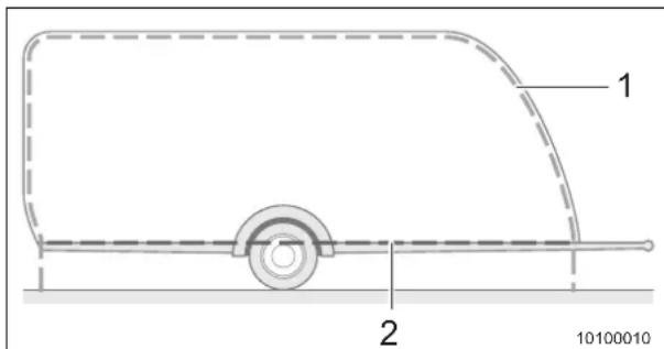
text_image
1 2 10100010Fig. 110 Awning A/A size and draught skirt size
1 Awning A/A size
2 Draught skirt size
Refer to the respective Table for the awning A/A sizes and draught skirt sizes
22.3.1 ACTION
| Body length [cm] Awning A/A size [cm] Draught skirt size [cm] | ||
| 361 737 -- | ||
Tab. 29 Awning A/A size and draught skirt size ACTION
Tab. 34 Awning A/A size and draught skirt size ADIVA
23 Checklists
i Important!
These lists also include special equipment and personal equipment not included in the standard caravan equipment.
23.1 Checklist caravan, general
| Checklist Caravan | √ |
| General inspection of caravan carried out (Chapter 2.4.1) | |
| Gas inspection carried out (Chapter 2.4.2) | |
| Maintenance and inspection work carried out (Chapter 20) | |
| Tyres not older than 6 years (only for 100 kmh approval) | |
| Wheel bolts, wheel nuts tightened correctly | |
| Tyre pressure checked (Chapter 22.1), tread depth checked | |
| Spare wheel tyre pressure or use-by date of tyre mobility system checked | |
| Lighting checked | |
| Nationality identification attached (when required in destination country) | |
| Emergency equipment available (warning triangle and first-aid kit, possibly flashing hazard warning light and warning vests in the towing vehicle) | |
| Fire extinguisher present and tested | |
| Tools: Gloves, reserve fuel canister (if allowed in the country being visited), jumper cable, tow rope, tow bar, vehicle jack, wheel chocks, wheel nut spanner, screwdriver, open-ended spanner, hammer, pliers, circuit tester, terminal clamps, fabric tape, folding spade, engine oil, tension belts | |
| Spare parts: Fuses, spare lights, hose clamps, hose, spare immersion pump, wire | |
| Snow chains, traction aids | |
| Bubble level, drive-on chocks | |
| CEE cable reel, extension cable, adapter cable | |
| Water hose, canister, watering can | |
| Water disinfectant, toilet cassette, etc. | |
| Gas cylinders, filled | |
| Gas cylinders securely attached in gas cylinder compartment (Chapter 11.5), screw plug and protective covers for all cylinders | |
| Quick-action stop valve for cooker, oven closed (Chapter 11.6) | |
| Gas adapter (filler set, cylinder set) | |
| Cranks and support plates for corner steadies | |
| Crank for awning | |
| Additional cushion for making the bed | |
| All ladders safely stowed | |
| Antenna retracted and secured | |
| All liquids stored in leak-proof containers | |
| All objects in open storage areas stowed securely | |
| Refrigerator, freezer compartment and oven doors latched securely | |
| Sink board safely stowed | |
| Cabinets and drawers latched securely | |
| Bathroom door latched securely | |
| All beds and bed extensions latched securely | |
| All tables safely stowed | |
| All windows and roof hoods closed securely | |
| Awning light switched off | |
| Awning retracted and latched securely | |
| 230V connecting cable removed from external socket | |
| Waste water tank drain valve closed | |
| Corner steadies retracted | |
| Drive-on chocks, wheel chocks removed | |
| Snow and ice cleared from roof | |
| Rear carrier loaded securely, warning sign attached securely | |
| Additional loads stored securely and prevented from shifting | |
| Vehicle loaded properly (Chapter 5.4) | |
| Permissible gross weight and gross axle weight rating of the vehicle not exceeded (see registration documents) | |
| Entrance step retracted | |
| All outer doors and flaps securely latched and locked |
Tab. 35 Checklist caravan, general
23.2 Driver and passengers checklist
| Driver and passengers checklist | ✓ |
| Identity cards, passport, visa (check validity!) | |
| Health insurance card, EU health insurance card, health insurance documents for abroad | |
| Travel health insurance documents | |
| Vaccination cards (vaccinations up to date?), allergy passes, emergency passes | |
| Required travel documents for all animals | |
| Driving licence, international driving licence | |
| Vehicle documents, green insurance card | |
| General inspection certificate, emissions test certificate, (towing vehicle), official gas inspection certificate | |
| Parking disc (towing vehicle) | |
| Operating instructions | |
| Authorised workshops, caravan and towing vehicle | |
| Spare vehicle key | |
| Spare glasses | |
| Window cloth | |
| Automobile club card, breakdown insurance package for coverage abroad | |
| Accident set with European accident report | |
| Apartment or house key | |
| Cash, foreign currencies | |
| Travel cheques | |
| EC card, credit card | |
| Toll stickers, toll tickets, ferry tickets, petrol coupons | |
| Road atlas, road maps | |
| Satnav, navigation CD or DVD (towing vehicle) | |
| Travel guides, camping and parking guide | |
| Camping site booking confirmation | |
| Phrase books, dictionaries | |
| Travel provisions | |
| Address book | |
| Mobile phone |
Tab. 36 Driver and passengers checklist
23.3 Living and sleeping area checklist
| Equipment | √ | Equipment | √ |
| Copies of: Identity cards, passports, visa | Copies of: Vaccination cards, allergy passes, emergency passes | ||
| Copies of: Driving licence, international driving licence | Copies of: Vehicle documents, green insurance card | ||
| Telephone number of local bank (if the EC card gets stolen) | Telephone number of credit card company (if the credit card gets stolen) | ||
| Clothes, shoes Pyjamas | |||
| Rainwear, winter clothes (hat, scarf, gloves, boots...) | Swimwear, bathrobe and slippers, diving goggles, flippers | ||
| Sports clothes, jogging gear Ski clothes | |||
| Umbrella Shoe polish | |||
| Pillows, blankets (Fitted) sheets, bed linens | |||
| Coat hangers Clothes brush, lint roller | |||
| Camping table, camping chairs Tent, awning | |||
| Table cloths, place mats, napkins, bibs | Insect | repellent candles / insect repellent lights, fly swatter | |
| Iron, sewing kit, scissors Pocket knife, multitool | |||
| Pocket light, candles | Rope, cord | ||
| Barbecue, charcoal, charcoal lighters | Batteries | ||
| Pencils and paper | Alarm clock | ||
| Books, CDs, DVDs | Radio | ||
| Sunglasses, sunhat, suncap | Audio equipment, photo equipment, video equipment | ||
| Rucksack | Games, painting accessories, cuddly toys | ||
| Binoculars | Dog collar, dog lead | ||
| Bicycles, tricycles, scooters | Bicycle locks with keys, repair kit | ||
| Air mattress, pump or compressor | Leisure equipment | ||
| Impregnating agent |
Tab. 37 Living area checklist
23.4 Kitchen checklist
| Equipment | √ | Equipment | √ |
| Food Bottle stopper | |||
| Baby food Glasses, mugs, cups | |||
| Carving knife, kitchen knife, bread knife | Plates (large/small), soup plates, soup bowls | ||
| Chopping board Bowls (large/small) | |||
| Gas lighters, matches Bread basket | |||
| Scissors, can opener Cutlery, ladles, salad servers | |||
| Pots, pans Airtight storage boxes | |||
| Pot coasters Aluminium foil, cling film, freezer bags | |||
| Pot holders Coolbag | |||
| Measuring cup Kitchen towels | |||
| Cooking spoons, spatula, egg whisk | Coffee machine, filter paper, kettle | ||
| Spices | Dishwashing brush, sponge, cloth | ||
| Pasta strainer, salad strainer | Tea towels | ||
| Dishwashing detergent | Cleaner | ||
| Tea pot, coffee pot, thermos flask | Tin opener, bottle opener, corkscrew | ||
| Bottle warmer | Broom, shovel | ||
| Egg boiler, egg cups | Dust bin, rubbish bag | ||
| Toaster | Grill utensils | ||
| Floor cloth, bucket | Dog bowl | ||
Tab. 38 Kitchen equipment checklist
23.5 Bathroom / sanitary equipment checklist
| Equipment | √ | Equipment | √ |
| Toilet bag Glasses, glasses cleaners | |||
| Toothbrush, toothpaste, beakers Contact lenses, cleaner, clear water | |||
| Shaver, razor blades / shaving brush / shaving foam | Body lotion, face creme, hand creme | ||
| Soap Toilet brush | |||
| Shower gel, shampoo Wet wipes | |||
| Flannels Nappies, changing mat | |||
| Towels, bathing towels, shower towels | Tampons, sanitary towels | ||
| Toilet paper (rapid dissolving) Contraceptives | |||
| Comb, brush, hair bands, hair slides Detergent, clotheslines, clothes pegs | |||
| Hair dryer, curling tongs Tissues | |||
| Mousse, hair spray | Disinfectant | ||
| Deodorant, fragrance | Sun protection products, aftersun | ||
| Cosmetic products, lip balm | Insect repellent lotion, insect repellent spray | ||
| Cotton swabs, cotton pads | First-aid kit and medicines with instruction leaflets | ||
| Nail scissors, nail file | Laundry bag | ||
| Tweezers Earplugs | |||
Tab. 39 Bathroom / sanitary equipment checklist
23.6 Personal checklist
Please copy and complete.
Route: Date:
| Personal checklist | √ |
Tab. 40 Personal checklist
Index
0-9
12 V mode, refrigerator .....73, 122
12 V power supply Battery selector switch ..... 75
12 V power supply unit 46
230 V mode, refrigerator 123
230 V power supply 68
A
Accessories Weights 164
Additional equipment Weights 164
Additional load 162
Alignment 25
Auxiliary heater, Ultraheat 101
Awning A/A size 166
B
Bathroom See bathroom unit 54
Bathroom unit .... 54 Washbasin, foldable .... 54
Battery Charging system .... 46 Starter battery .... 77 Towing vehicle .... 77
Bed Bunk bed ....63 Fixed bed ....62 Foldaway bed ....64
Before the journey 15
Blind Darkening .... 37 Insect screen .... 37
Blinds 37
Bodywork Description 12
Boiler Exhaust cowl 111
Breakaway cable 15
Breakaway safety, see breakaway cable 15
Bunk bed 63 Guard against falling 63
Butane gas 90
C
Care 141
Carpet floor 144
Curtains 144
Cushions 144
Furniture 143
Interior 143
Net curtains 144
Outside 141
PVC floor 144
Roof hoods 142
Care of carpet floor 144
Care of curtains 144
Care of cushions 144
Care of PVC floor 144
Cassette 130
Central lighting control 48
Changing the wheel 152
Changing wheels 150
Check before starting to drive 23
Checklist Bathroom / sanitary 174
Driver and passengers 171
General 169
Kitchen 173
Living and sleeping area 172
Personal 175
Returning to service after the placing out of service ..... 140
Temporary placing out of service . . 137
Winter camping 136
Winter, placing out of service ..... 139
Circulation fan 101
City water connection 97
Cleaning Bathroom 146
Gas stove 144
Kitchen 144
Outside 141
Oven 145
Plastic parts 142
Refrigerator 145
Cleaning of plastic parts 142
Cleaning the acrylic windows 142
Cleaning the bathroom 146
Cleaning the kitchen 144
Control panel 46
LT 413 46
See control panel 46
Type EN 47
Cooking 112
Extractor hood 114
Gas stove 116
Microwave oven 115
Corner steadies 25
Coupling 15, 16
AK 150/160/200 16
AK 251 16
AK 300 16
AKS 1300 17
AKS 3004 18
BPW WS 3000 D 19
Coupling, stabilizer lever 15
D
Description & equipment 12
Door
Entrance door 29
Refrigerator 119
Draught skirt size 166
During the journey 24
E
Electrical connection 26
Electrical diagram 81
Electrical floor heating 102
Entrance door 29
Entrance step 26
Electrical 27
Environmental tips 11
Exhaust cowl, right 111
Exterior lighting 154
External connection Water tank 97
External gas connection 94
Extractor hood 114
F
Faucet 98
Fire 10
Fire prevention 10
Fixed bed 62
Flat blade fuses 72, 74, 77
Floor heating 102
Foldaway bed, wall unit 64
Exhaust cowl, right ..... 111
External gas connection 94
Gas cylinder compartment ..... 90
Gas pressure regulator 92
Gas stove 112
Gas system 89
Inspection certificate 89
Malfunctions 161
Quick-action stop valves 92
Refrigerator mode 123
Stove 116
Types 90
Grill 116
Guard against falling
Bunk bed 63
Foldaway bed, wall unit 64
H
Handle
Entrance door 29
Furniture 51
Heater 100
Alde warm water heater ..... 109
Auxiliary heater, Ultraheat ..... 101
Circulation fan 101
Floor heating 102
Fluid level 149
Truma Boiler 106
Truma Therme 104
Warm air 100
Warm air distribution ..... 111
Hinged windows 33
|
Insect screens 37
Inspection work 147
K
Keys
Spare keys 23
L
Light bulbs, exterior lighting 154
Lighting control
Central 48
Lighting, exterior 154
Lights
Lighting control 48
Outside 155
Liquid gas 91
Living area battery 78
Living in the caravan 29
Loading 20
M
Maintenance
Bodywork 148
Chassis 148
Microwave oven 115
Mirrors
Towing vehicle 22
N
Net curtains, care 144
0
Official technical inspections 6
Gas system 6
Operating fluids 149
Operating panel
LT 413 46
Type EN 47
Oven 116
Overrun device shaft 15
P
Parking area requirements ..... 25
Pitching the caravan 25
Placing into service
After placing out of service ..... 140
Vehicle 14
Placing out of service 137
Checklist 137
over winter 139
Temporary 137
Placing the vehicle into service for the first time 14
Power supply 68
Propane gas 90
Q
Quick-action stop valves 92
R
Rear view mirrors 22
Reference values for gas consumption 91
Refrigerator 118
12 V mode 73, 122
230 V mode 123
Dometic 7 series 120
Dometic 8 series, automatic ignition 121
Dometic 8 series, manual ignition . . 121
Door opener 119
Frame heater 122
Gas operation 123
Putting out of operation 124
Thetford Premium LCD 122
Winter operation 124
Registration of vehicle 14
Roof hood
Blind/insect screen running in opposite directions 43
Blind/insect screen running in the same direction 44
Blind/insect screen running together 45
Care 142
Roof hood blind/insect screen
Running in opposite directions ..... 43
Running in the same direction ..... 44
Running together 45
Roof openings 39
Roof hood with crank operation .... 40
Roof hood with operating bar ..... 40
Roof hood with rotary handle ..... 41
S
Safety instructions 4
Seating group 50
Shower
Folding door 55
Sleeping arrangements 62
Sliding window 36
Spare keys 23
Step Electrical 27
T
Table Lowering 65
Tank Waste water 98 Water tank 96
Technical data 162
Tightening the wheel nuts 153
Toilet 125
Troubleshooting 150 Bulbs 154 Changing wheels 150 Control/switching panel 160 Freezer compartment 161 Gas stove 161 Gas system 161 Lighting control 161 Power supply 159 Refrigerator 161 Toilet 155 Water supply 155
Truma Therme 104
TV bracket 57
TV equipment 57
Tyres 22
Mobility system 150
Pressure 162
See also tyres 22
U
Ultraheat, auxiliary heater .... 101 Uncoupling .... 19
V
Vehicle Data .... 3 Loading .... 20 Registration .... 14
Vehicle jack 151 Ventilation 32
W
Warm air distribution 111
Warm air heater 100
Warm water heater Alde .... 109 Fluid level .... 149
Warranty Vehicle data .... 3 Warranty registration .... 3
Washbasin Foldable 54
Waste water 98 Draining the system 99 Tank (mobile) 28
Water supply 95
Water tank
City connection 97
External connection 97
Faucet 98
Position 50
Water/waste water Draining the system ..... 99 Tank, cleaning ..... 146
Weights Additional equipment ..... 164
Wheel arch insert .... 15 Window See hinged window .... 33 Sliding window .... 36
Winter camping 134 Checklist 136
Winter operation Refrigerator .... 124