926N - Pressure washer Hotsy - Free user manual and instructions
Find the device manual for free 926N Hotsy in PDF.


User questions about 926N Hotsy
0 question about this device. Answer the ones you know or ask your own.
Ask a new question about this device
Download the instructions for your Pressure washer in PDF format for free! Find your manual 926N - Hotsy and take your electronic device back in hand. On this page are published all the documents necessary for the use of your device. 926N by Hotsy.
USER MANUAL 926N Hotsy
natural_image
Technical line drawing of a white industrial machine with internal components and mounting brackets (no text or symbols)Introduction & Important Safety Information 8-10
Component Identification 11
Assembly Instructions 12
Installation Instructions 13-16
Operation Instructions 17-18
Shutdown Instructions 19
Storage 19
Maintenance 20
Troubleshooting 21-25
Warranty
WARNING: If the information in this manual is not followed exactly, a fire or explosion may result causing property damage, personal injury or death.
Do not store or use gasoline or other flammable vapors and liquids in the vicinity of this or any other appliance.
WHAT TO DO IF YOU SMELL GAS
• Do not try to light any appliance.
- Do not touch any electrical switch; do not use any phone in your building.
- Immediately call your gas supplier from a neighbor's phone. Follow the gas supplier's instructions.
• If you cannot reach your gas supplier, call the fire department.
Installation and service must be performed by a qualified installer, service agency or the gas supplier.
Model Number ____
Serial Number
Date of Purchase ____
The model and serial numbers will be found on a decal attached to the pressure washer. You should record both serial number and date of purchase and keep in a safe place for future reference.
1.109-691.0 921N SPECIFICATIONS
● Pump Volume At Pump Head: 4.0 GPM/228 GPH
● Pump Pressure At Pump Head: 2300 PSI
● Burner Type: Natural Gas Fired, 390,000 BTU/Hr.
● Motor Hp: 6.2
● Machine Voltage: 208Vac/60Hz/1Ph
● Total Machine Amperage: 28 Amps
● Machine Weight: 560 Lbs.
● Shipping Weight: 620 Lbs.
● Exhaust Stack Size: 8"
● Machine Dimensions: Length=45", Width=18", Height=50"
1.109-692.0 926N SPECIFICATIONS
● Pump Volume At Pump Head: 4.0 GPM/228 GPH
● Pump Pressure At Pump Head: 2300 PSI
● Burner Type: Natural Gas Fired, 390,000 BTU/Hr.
● Motor Hp: 5
● Machine Voltage: 575Vac/60Hz/3Ph
● Total Machine Amperage: 7 Amps
● Machine Weight: 555 Lbs.
● Shipping Weight: 610 Lbs.
● Exhaust Stack Size: 8"
● Machine Dimensions: Length=45", Width=18", Height=50"
1.109-695.0 943P SPECIFICATIONS
● Pump Volume At Pump Head: 4.0 GPM/234 GPH
● Pump Pressure At Pump Head: 2000 PSI
● Burner Type: LP Gas Fired, 378,600 BTU/Hr.
● Motor Hp: 5.0
● Machine Voltage: 230VAC/60Hz/1Ph
● Total Machine Amperage: 25 Amps
● Machine Weight: 550 Lbs.
● Shipping Weight: 610 Lbs.
● Exhaust Stack Size: 8'
● Machine Dimensions: Length=45", Width=18", Height=50"
1.109-696.0 943N SPECIFICATIONS
● Pump Volume At Pump Head: 4.0 GPM/234 GPH
● Pump Pressure At Pump Head: 2000 PSI
● Burner Type: Natural Gas Fired, 390,000 BTU/Hr.
● Motor Hp: 5.0
● Machine Voltage: 230Vac/60Hz/1Ph
● Total Machine Amperage: 25 Amps
● Machine Weight: 550 Lbs.
● Shipping Weight: 610 Lbs.
● Exhaust Stack Size: 8"
● Machine Dimensions: Length=45", Width=18", Height=50"
1.109-697.0 944P SPECIFICATIONS
● Pump Volume At Pump Head: 4.0 GPM/234 GPH
● Pump Pressure At Pump Head: 2000 PSI
● Burner Type: LP Gas Fired, 378,600 BTU/Hr.
● Motor Hp: 5.0
● Machine Voltage: 230Vac/60Hz/3Ph
● Total Machine Amperage: 16 Amps
● Machine Weight: 545 Lbs.
● Shipping Weight: 605 Lbs.
● Exhaust Stack Size: 8"
● Machine Dimensions: Length=45", Width=18", Height=50"
1.109-698.0 944N SPECIFICATIONS
● Pump Volume At Pump Head: 4.0 GPM/234 GPH
● Pump Pressure At Pump Head: 2000 PSI
● Burner Type: NG Gas Fired, 390,000 BTU/Hr.
● Motor Hp: 5.0
● Machine Voltage: 230Vac/60Hz/3Ph
● Total Machine Amperage: 16 Amps
● Machine Weight: 545 Lbs.
● Shipping Weight: 605 Lbs.
● Exhaust Stack Size: 8"
● Machine Dimensions: Length=45", Width=18", Height=50"
1.109-693.0 942P SPECIFICATIONS
● Pump Volume At Pump Head: 4.0 GPM/234 GPH
● Pump Pressure At Pump Head: 2000 PSI
● Burner Type: LP Gas Fired, 378,600 BTU/Hr.
● Motor Hp: 5.0
● Machine Voltage: 230Vac/60Hz/3Ph
● Total Machine Amperage: 16 Amps
● Machine Weight: 545 Lbs.
● Shipping Weight: 605 Lbs.
● Exhaust Stack Size: 8"
● Machine Dimensions: Length=45", Width=18", Height=50"
1.109-694.0 942N SPECIFICATIONS
● Pump Volume At Pump Head: 4.0 GPM/234 GPH
● Pump Pressure At Pump Head: 2000 PSI
● Burner Type: Natural Gas Fired, 390,000 BTU/Hr.
● Motor Hp: 5.0
● Machine Voltage: 208Vac/60Hz/3Ph
● Total Machine Amperage: 18 Amps
● Machine Weight: 545 Lbs.
● Shipping Weight: 605 Lbs.
● Exhaust Stack Size: 8"
● Machine Dimensions: Length=45", Width=18", Height=50"
1.109-699.0 945P SPECIFICATIONS
● Pump Volume At Pump Head: 4.0 GPM/234 GPH
● Pump Pressure At Pump Head: 2000 PSI
● Burner Type: LP Gas Fired, 378,600 BTU/Hr.
● Motor Hp: 5.0
● Machine Voltage: 460Vac/60Hz/3Ph
● Total Machine Amperage: 8 Amps
● Machine Weight: 545 Lbs.
● Shipping Weight: 605 Lbs.
● Exhaust Stack Size: 8"
● Machine Dimensions: Length=45", Width=18", Height=50"
1.109-700.0 945N SPECIFICATIONS
● Pump Volume At Pump Head: 4.0 GPM/234 GPH
● Pump Pressure At Pump Head: 2000 PSI
● Burner Type: Natural Gas Fired, 390,000 BTU/Hr.
● Motor Hp: 5.0
● Machine Voltage: 460Vac/60Hz/3Ph
● Total Machine Amperage: 8 Amps
● Machine Weight: 545 Lbs.
● Shipping Weight: 605 Lbs.
● Exhaust Stack Size: 8"
● Machine Dimensions: Length=45", Width=18", Height=50"
1.109-704.0 1453P SPECIFICATIONS
● Pump Volume At Pump Head: 4.0 GPM/234 GPH
● Pump Pressure At Pump Head: 3000 PSI
● Burner Type: LP Gas Fired, 378,600 BTU/Hr.
● Motor Hp: 7.5
● Machine Voltage: 230VAC/60Hz/1Ph
● Total Machine Amperage: 34 Amps
● Machine Weight: 610 Lbs.
● Shipping Weight: 670 Lbs.
● Exhaust Stack Size: 8"
● Machine Dimensions: Length=45", Width=18", Height=50"
1.109-705.0 1453N SPECIFICATIONS
● Pump Volume At Pump Head: 4.0 GPM/234 GPH
● Pump Pressure At Pump Head: 3000 PSI
● Burner Type: Natural Gas Fired, 390,000 BTU/Hr.
● Motor Hp: 7.5
● Machine Voltage: 230VAC/60Hz/1Ph
● Total Machine Amperage: 34 Amps
● Machine Weight: 610 Lbs.
● Shipping Weight: 670 Lbs.
● Exhaust Stack Size: 8"
● Machine Dimensions: Length=45", Width=18", Height=50"
1.109-706.0 1454P SPECIFICATIONS
● Pump Volume At Pump Head: 4.0 GPM/234 GPH
● Pump Pressure At Pump Head: 3000 PSI
● Burner Type: LP Gas Fired, 378,600 BTU/Hr.
● Motor Hp: 7.5
● Machine Voltage: 230VAC/60Hz/3Ph
● Total Machine Amperage: 25 Amps
● Machine Weight: 605 Lbs.
● Shipping Weight: 665 Lbs.
● Exhaust Stack Size: 8"
● Machine Dimensions: Length=45", Width=18", Height=50"
1.109-702.0 1452P SPECIFICATIONS
● Pump Volume At Pump Head: 4.0 GPM/234 GPH
● Pump Pressure At Pump Head: 3000 PSI
● Burner Type: LP Gas Fired, 378,600 BTU/Hr.
● Motor Hp: 7.5
● Machine Voltage: 208VAC/60Hz/3Ph
● Total Machine Amperage: 24 Amps
● Machine Weight: 605 Lbs.
● Shipping Weight: 665 Lbs.
● Exhaust Stack Size: 8"
● Machine Dimensions: Length=45", Width=18", Height=50"
1.109-707.0 1454N SPECIFICATIONS
● Pump Volume At Pump Head: 4.0 GPM/234 GPH
● Pump Pressure At Pump Head: 3000 PSI
● Burner Type: Natural Gas Fired, 390,000 BTU/Hr.
● Motor Hp: 7.5
● Machine Voltage: 230Vac/60Hz/3Ph
● Total Machine Amperage: 24 Amps
● Machine Weight: 605 Lbs.
● Shipping Weight: 665 Lbs.
● Exhaust Stack Size: 8"
● Machine Dimensions: Length=45", Width=18", Height=50"
1.109-703.0 1452N SPECIFICATIONS
● Pump Volume At Pump Head: 4.0 GPM/234 GPH
● Pump Pressure At Pump Head: 3000 PSI
● Burner Type: Natural Gas Fired, 390,000 BTU/Hr.
● Motor Hp: 7.5
● Machine Voltage: 208Vac/60Hz/3Ph
● Total Machine Amperage: 24 Amps
● Machine Weight: 605 Lbs.
● Shipping Weight: 655 Lbs.
● Exhaust Stack Size: 8"
● Machine Dimensions: Length=45", Width=18", Height=50"
1.109-708.0 1455P SPECIFICATIONS
● Pump Volume At Pump Head: 4.0 GPM/234 GPH
● Pump Pressure At Pump Head: 3000 PSI
● Burner Type: LP Gas Fired, 378,600 BTU/Hr.
● Motor Hp: 7.5
● Machine Voltage: 460Vac/60Hz/3Ph
● Total Machine Amperage: 12 Amps
● Machine Weight: 605 Lbs.
● Shipping Weight: 665 Lbs.
● Exhaust Stack Size: 8"
● Machine Dimensions: Length=45", Width=18", Height=50"
1.109-709.0 1455N SPECIFICATIONS
● Pump Volume At Pump Head: 4.0 GPM/234 GPH
● Pump Pressure At Pump Head: 3000 PSI
● Burner Type: Natural Gas Fired, 390,000 BTU/Hr.
● Motor Hp: 7.5
● Machine Voltage: 460Vac/60Hz/3Ph
● Total Machine Amperage: 12 Amps
● Machine Weight: 605 Lbs.
● Shipping Weight: 665 Lbs.
● Exhaust Stack Size: 8"
● Machine Dimensions: Length=45", Width=18", Height=50"
1.109-701.0 1451N SPECIFICATIONS
● Pump Volume At Pump Head: 4.0 GPM/234 GPH
● Pump Pressure At Pump Head: 3000 PSI
● Burner Type: Natural Gas Fired, 390,000 BTU/Hr.
● Motor Hp: 8.2
● Machine Voltage: 208Vac/60Hz/1Ph
● Total Machine Amperage: 36.5 Amps
● Machine Weight: 615 Lbs.
● Shipping Weight: 675 Lbs.
● Exhaust Stack Size: 8"
● Machine Dimensions: Length=45", Width=18", Height=50"
1.109-710.0 1456N SPECIFICATIONS
● Pump Volume At Pump Head: 4.0 GPM/234 GPH
● Pump Pressure At Pump Head: 3000 PSI
● Burner Type: Natural Gas Fired, 390,000 BTU/Hr.
● Motor Hp: 8.2
● Machine Voltage: 575Vac/60Hz/3Ph
● Total Machine Amperage: 10 Amps
● Machine Weight: 615 Lbs.
● Shipping Weight: 675 Lbs.
● Exhaust Stack Size: 8"
● Machine Dimensions: Length=45", Width=18", Height=50"
1.109-713.0 1473N SPECIFICATIONS
● Pump Volume At Pump Head: 5 GPM/300 GPH
● Pump Pressure At Pump Head: 3000 PSI
● Burner Type: Natural Gas Fired, 390,000 BTU/Hr.
● Motor Hp: 10 HP
● Machine Voltage: 230Vac/60Hz/1Ph
● Total Machine Amperage: 42 Amps
● Machine Weight: Lbs.
● Shipping Weight: Lbs.
● Exhaust Stack Size: 8"
● Machine Dimensions: Length=45", Width=18", Height=50"
1.109-714.0 1474N SPECIFICATIONS
● Pump Volume At Pump Head: 5 GPM/300 GPH
● Pump Pressure At Pump Head: 3000 PSI
● Burner Type: LP Gas Fired, 390,000 BTU/Hr.
● Motor Hp: 10 HP
● Machine Voltage: 230Vac/60Hz/3Ph
● Total Machine Amperage: 29 Amps
● Machine Weight: Lbs.
● Shipping Weight: Lbs.
● Exhaust Stack Size: 8"
● Machine Dimensions: Length=45", Width=18", Height=50"
1.109-711.0 1473P SPECIFICATIONS
● Pump Volume At Pump Head: 5 GPM/300 GPH
● Pump Pressure At Pump Head: 3000 PSI
● Burner Type: LP Gas Fired, 378,600 BTU/Hr.
● Motor Hp: 10 HP
● Machine Voltage: 730Vac/60Hz/1Ph
● Total Machine Amperage: 42 Amps
● Machine Weight: Lbs.
● Shipping Weight: Lbs.
● Exhaust Stack Size: 8"
● Machine Dimensions: Length=45", Width=18", Height=50"
1.109-712.0 1474P SPECIFICATIONS
● Pump Volume At Pump Head: 5 GPM/300 GPH
● Pump Pressure At Pump Head: 3000 PSI
● Burner Type: Natural Gas Fired, 378,600 BTU/Hr.
● Motor Hp: 10 HP
● Machine Voltage: 230Vac/60Hz/3Ph
● Total Machine Amperage: 29 Amps
● Machine Weight: Lbs.
● Shipping Weight: Lbs.
● Exhaust Stack Size: 8"
● Machine Dimensions: Length=45", Width=18", Height=50"
INTRODUCTION & IMPORTANT SAFETY INFORMATION
Thank you for purchasing this Pressure Washer. We reserve the right to make changes at any time without incurring any obligation.
Owner/User Responsibility:
The owner and/or user must have an understanding of the manufacturer's operating instructions and warnings before using this pressure washer. Warning information should be emphasized and understood. If the operator is not fluent in English, the manufacturer's instructions and warnings shall be read to and discussed with the operator in the operator's native language by the purchaser/owner, making sure that the operator comprehends its contents.
Owner and/or user must study and maintain for future reference the manufacturers' instructions.
The operator must know how to stop the machine quickly and understand the operation of all controls. Never permit anyone to operate the engine without proper instructions.
SAVE THESE INSTRUCTIONS
This manual should be considered a permanent part of the machine and should remain with it if machine is resold.
When ordering parts, please specify model and serial number. Use only identical replacement parts.
This machine is to be used only by trained operators.
IMPORTANT SAFETY INFORMATION
WARNING: If you do not follow these instructions exactly, a fire or explosion may result, causing property damage, personal injury or loss of life.

text_image
WARNING READ OPERATOR'S MANUAL THOROUGHLY PRIOR TO USE.WARNING: To reduce the risk of injury, read operating instructions carefully before using.
-
Read the owner's manual thoroughly. Failure to follow instructions and warnings could cause malfunction of the machine and result in death, serious bodily injury and/or property damage.
-
Know how to stop the machine and bleed pressure quickly. Be thoroughly familiar with the controls.
- Stay alert — watch what you are doing.
-
Use only your hand to push in or turn the gas control knob. Never use a tool. If the knob will not push in or turn by hand, don't try to repair it; call a qualified service technician.
-
All installations must comply with local codes. Contact your electrician, plumber, utility company or the selling distributor for specific details.
DANGER: Improper connection of the equipment-grounding conductor can result in a risk of electrocution. Check with a qualified electrician or service personnel if you are in doubt as to whether the outlet is properly grounded.
text_image
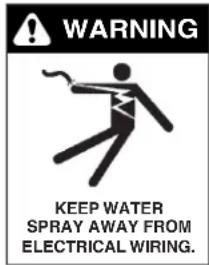
WARNING KEEP WATER SPRAY AWAY FROM ELECTRICAL WIRING.WARNING: Keep wand, hose, and water spray away from electric wiring or fatal electric shock may result.
- To protect the operator from electrical shock, the machine must be electrically grounded. It is the responsibility of the owner to connect this
machine to a grounded receptacle of proper voltage and amperage ratings. Do not spray water on or near electrical components. Do not touch machine with wet hands or while standing in water. Always disconnect power before servicing.
text_image
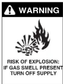
WARNING RISK OF EXPLOSION: IF GAS SMELL PRESENT TURN OFF SUPPLYWARNING: Flammable liquids can create fumes which can ignite, causing property damage or severe injury.
WARNING: Risk of explosion — Operate only where open flame or torch is permitted. Do not spray flammable liquids.
text_image
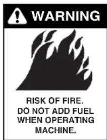
WARNING RISK OF FIRE. DO NOT ADD FUEL WHEN OPERATING MACHINE.WARNING: Risk of fire — Do not change LP tanks when the product is operating or still hot. WARNING: Use vapor fuel only.
- Gas appliances shall be installed only in locations where combustible dusts and flammable gases or vapors are not present. Do not store or use gasoline near this machine.
WARNING: In the event of a pilot outage, wait at least five minutes to clear out any gas before relighting.
- Keep operating area clear of all persons.
IMPORTANT SAFETY INFORMATION

text_image
WARNING USE PROTECTIVE EYE WEAR AND CLOTHING WHEN OPERATING THIS EQUIPMENT.WARNING: High pressure spray can cause paint chips or other particles to become airborne and fly at high speeds. To avoid personal injury, eye, hand and foot safety devices must be worn.
- Eye, hand, and foot protection must be worn when using this equipment.

text_image
WARNING EAR PROTECTION MUST BE WORNWARNING: This machine exceeds 85 db appropriate ear protection must be worn.

text_image
WARNING RISK OF INJURY. HOT SURFACES CAN CAUSE BURNSWARNING: Risk of injury. Hot surfaces can cause burns. Use only designated gripping areas of spray gun and wand. Do not place hands or feet on non-insulated areas of the pressure washer.
- To reduce risk of injury, close supervision is necessary when a machine is used near children. Do not allow children to operate pressure washer. This machine must be attended during operation.
text_image
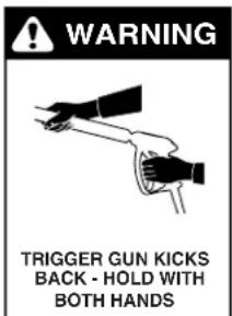
WARNING TRIGGER GUN KICKS BACK - HOLD WITH BOTH HANDSWARNING: Grip cleaning wand securely with both hands before starting. Failure to do this could result in injury from a whipping wand.
- Never make adjustments on machine while in operation.
- Move spray gun trigger lever into locked position before
inserting the high pressure nozzle into the quick coupler. Be certain all quick coupler fittings are secured before using pressure washer.
text_image
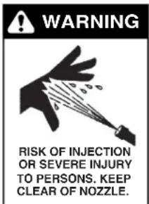
WARNING RISK OF INJECTION OR SEVERE INJURY TO PERSONS. KEEP CLEAR OF NOZZLE.WARNING: High pressure developed by these machines will cause personal injury or equipment damage. Keep clear of nozzle. Use caution when operating. Do not direct discharge stream at people, or severe injury or death will result.

text_image
WARNING PROTECT FROM FREEZINGWARNING: Protect machine from freezing.
- To keep machine in best operating conditions, it is important you protect machine from freezing. Failure to protect machine from freezing could cause malfunction of the machine and result in death, injury, and/or property damage. Foli-tructions specified in this manual.
text_image
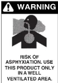
WARNING RISK OF ASPHYXIAION. USE THIS PRODUCT ONLY IN A WELL VENTILATED AREA.WARNING: Risk of asphyxiation. Use this product only in a well ventilated area.
-
Avoid installing machines in small areas or near exhaust fans. Adequate oxygen is needed for combustion or dangerous carbon monoxide will result.
-
Manufacturer will not be liable for any changes made to our standard machines or any components not purchased from us.
-
The best insurance against an accident is precaution and knowledge of the machine.

text_image
WARNING RISK OF INJURY FROM FALLS WHEN USING LADDER.WARNING: Be extremely careful when using a ladder, scaffolding or any other relatively unstable location. The cleaning area should have adequate slopes and drainage to reduce the possibility of a fall due to slippery surfaces.
- Do not overreach or stand on unstable support. Keep good footing and balance at all times.
- Do not operate this machine when fatigued or under the influence of alcohol, prescription medications, or drugs.
- Follow the maintenance instructions specified in the manual.
WARNING: Use vapor fuel only.
- The LP models are designed to run on vapor propane fuel. Do not use liquid fuel. Have a qualified serviceman install and service your equipment.
- Never expose a spark or flame where there may be unburned gas present.
IMPORTANT SAFETY INFORMATION
- Install this machine about 2 feet from wall to provide adequate ventilation and servicing space. This equipment incorporates parts such as snap switches or similar parts that tend to produce arcs or sparks. Therefore, when located in a garage, it should be in a room or enclosure provided for the purpose or should be installed 18" (457mm) or more above the floor.
WARNING: To reduce the risk of electric shock, disconnect all electrical connections and shut-off gas valve before servicing.
- Install this machine on non combustible flooring.
- Do not allow acids, caustic or abrasive fluids to pass through the pump.
- Never run pump dry or leave spray gun closed longer than 3 minutes.
WARNING: If connection is made to potable water supply, a back flow device must be provided.
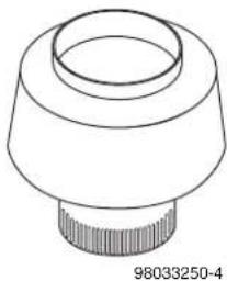
26. Exhaust gases should not be vented into a wall, a ceiling or a concealed space of a building. A draft diverter must be installed to prevent down draft and to allow cooling of exhaust temperatures. Down draft diverters shall be installed in the vents and located at a distance from the pressure washer stack to achieve maximum draft of 36" minimum.
natural_image
Technical line drawing of a mechanical component with a flanged top and threaded base (no text or symbols)Exhaust gases that exceed 470^ F ( 243^ C) are not suitable for connection to Type B gas vents.
Example of Down Draft Diverter for Gas Fired Machines

Follow the maintenance instructions specified in the manual.
text_image
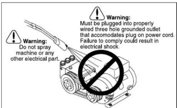
Warning: Do not spray machine or any other electrical part. Warning: Must be plugged into properly wired three hole grounded outlet that accommodates plug on power cord. Failure to comply could result in electrical shock.COMPONENT IDENTIFICATION
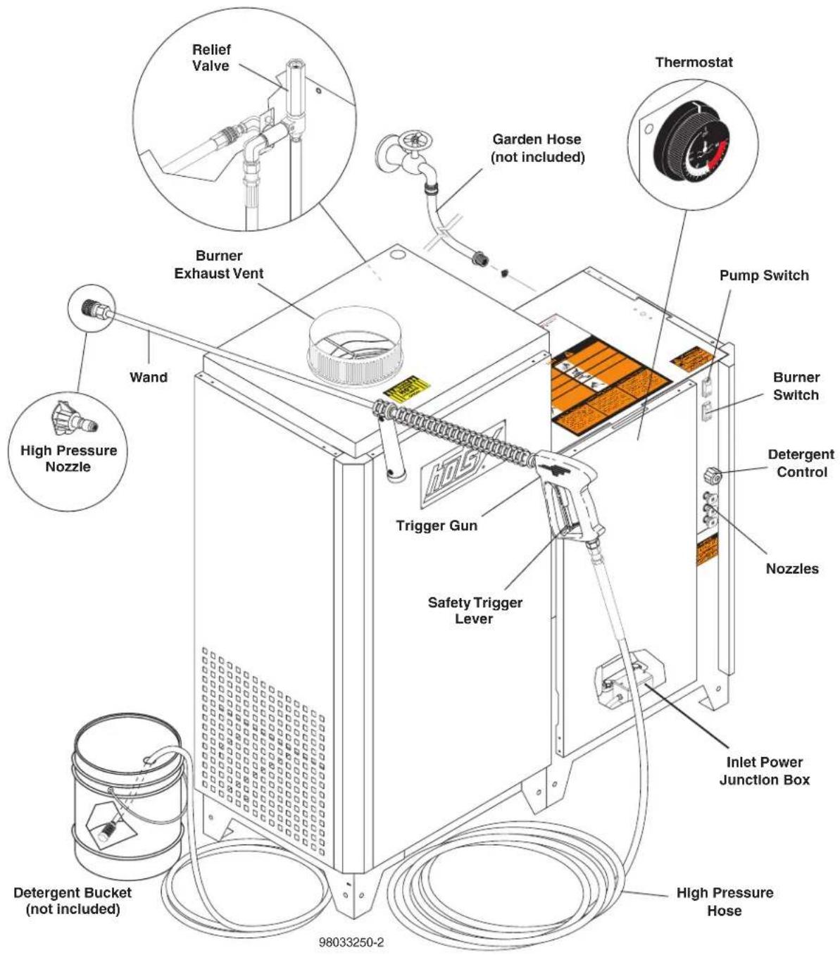
text_image
Relief Valve Garden Hose (not included) Thermostat Burner Exhaust Vent Pump Switch Wand High Pressure Nozzle Trigger Gun Safety Trigger Lever Detergent Bucket (not included) 98033250-2 Inlet Power Junction Box Detergent Control Nozzles Burner SwitchPump — Develops high pressure by pumping water volume through nozzle.
Spray Gun — Controls the application of water and detergent onto cleaning surface with trigger device. Includes safety latch.
Detergent Metering Valve — Controls detergent mixture.
Wand — Must be connected to the spray gun.
High Pressure Hose — Connect one end to water pump discharge nipple and the other end to spray gun.
Pressure Nozzle — Inserted into wand quick coupler to develop pressure
Adjustable Thermostat — Prevents water temperature from exceeding high temperatures. Is not used to maintain constant temperature setting.
Safety Trigger Lever — Prevents accidental triggering of spray gun while inserting a high pressure nozzle.
ASSEMBLY INSTRUCTIONS
Unpacking
Unpack carefully. Wear safety glasses or goggles while unpacking, assembling or operating pressure washer. If there are missing components or hidden damage immediately contact distributor or carrier concerning discrepancies.
- Cut strapping band from pressure washer and pallet.
- Remove pressure washer from pallet.
Parts Included
- Pressure Washer
- Pressure Hose
- Wand
- Parts Box Containing:
■ Pressure Nozzles (3 ea.)
■ Trigger Gun
• Operating Instructions and Parts Manual
Tools Required
• 10" Adjustable Crescent Wrenches (2 ea.)
- Blade Screwdriver
Pressure Hose, Wand and Wand Holder
- Use teflon tape on plumbing connections to prevent leakage.
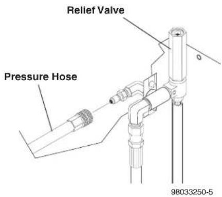
- Install pressure hose on machine as shown.
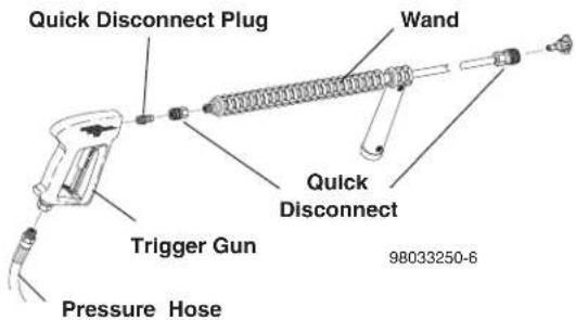
- Assemble wand components as shown. Connect pressure hose to trigger gun.
NOTE: The nozzle is not to be installed at this time.
text_image
Relief Valve Pressure Hose 98033250-5- Make sure that all plumbing connections are tight.
text_image
Quick Disconnect Plug Wand Quick Disconnect Trigger Gun Pressure Hose 98033250-6INSTALLATION INSTRUCTIONS
Getting Started:
IMPORTANT: Proper installation will assure satisfactory performance, longer service life and lower maintenance costs.
Location:
The location should protect machine from damaging environmental conditions, such as wind, rain and freezing.
- The machine should be run on a level surface where it is not readily influenced by outside sources such as strong winds, freezing temperatures, rain, etc. The machine should be located considering accessibility for the replacing of components and the refilling of detergents, adjustments and maintenance. Normal precautions should be taken by the operator of the machine to prevent excess moisture from reaching the machine.
- It is recommended that a partition be made between the wash area and machine to prevent direct spray from the spray gun from coming in contact with the machine. Excess moisture reaching the power unit or electrical controls will reduce the machine's life and may cause electrical shorts.
- During installation of the machine, beware of poorly ventilated locations or areas where exhaust fans may cause an insufficient supply of oxygen. Sufficient combustion can only be obtained when there is a sufficient supply of oxygen available for the amount of fuel being burned. If it is necessary to install a machine in a poorly ventilated area, outside fresh air may have to be piped to the burner and a fan installed to bring the air into the area.
- Do not locate near any combustible material. Keep all flammable material at least 20 feet away.
Allow enough space for servicing the machine.
Local code will require certain distances from floor and walls. (Two feet away should be adequate).
WARNING: Avoid small areas or near exhaust fans.
Gas Codes:
Confer with local gas company and with proper municipal officials regarding any specific code or regulations governing the installation. The installation must conform to local codes (U.S., ANSI Z223.1/NFPA54 National Fuel Gas Code; Canada, CAN 1-B149 Installation Code).
Electrical:
The machine, when installed, must be electrically grounded in accordance to local codes. Check for proper power supply using a volt meter; check the serial plate for the correct requirements.
Gas Piping:
This machine shall be rigidly connected to the gas piping outlet and equipped with external manual shut-off valves adjacent to such machine. All gas piping shall be approved and installed in accordance with the Uniform Mechanical Code.
Install a gas union in the gas line adjacent to and upstream from the control manifold and downstream from the manual main shut-off valve. A 1/8" NPT plugged tapping accessible for test gauge connection shall be installed immediately upstream of the gas supply connection for the purpose of determining the gas supply
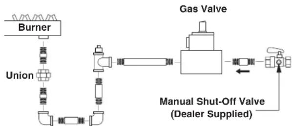
flowchart
graph LR
    A["Burner"] --> B["Union"]
    B --> C["Valve"]
    C --> D["Gas Valve"]
    D --> E["Manual Shut-Off Valve (Dealer Supplied)"]
    E --> F["Valve"]
    style A fill:#f9f,stroke:#333
    style B fill:#ccf,stroke:#333
    style C fill:#cfc,stroke:#333
    style D fill:#fcc,stroke:#333
    style E fill:#cff,stroke:#333
98033250-10
pressure to the burner, and to prevent damage to gas valve.
If a manual gas shut off valve is not in the gas supply line within six feet of the machine and in an accessible location, one shall be installed.
Figure 1: Union Location
Union Connection
The following pipe sizes are just recommendations. Always consult a local plumber and venting contractor for local codes and regulations during installation.
Pipe Sizing Chart for Natural Gas
The following chart is based on gas pressure in the range 0-0.5 psi, specific gravity of 0.6 and pressure loss of 0.5" W.C. Numbers are for straight schedule 40 pipe; fittings further reduce capacity. For example, in 1" size, an elbow is equivalent to about 2.6 feet of pipe and a tee is equivalent to about 5.2 feet of pipe.
Maximum capacity of pipe in cubic feet/hr of natural gas (Multiply values by 1000 to get nominal BTU/hr capacity.
INSTALLATION INSTRUCTIONS
LP-Gas (Liquid petroleum gas or propane)
| Length of Pipe (ft.) | Iron Pipe Size | ||||
| 3/4" | 1" | 1-1/4" | 1-1/2" | 2" | |
| 10 360 | 680 | 1400 | 2100 | 3950 | |
| 20 250 | 465 | 950 | 1 | 460 | 2750 |
| 30 200 | 375 | 770 | 1 | 180 | 2200 |
| 40 170 | 320 | 660 | 990 | 1 | 900 |
| 50 151 | 285 | 580 | 900 | 1 | 680 |
| 60 138 | 260 | 530 | 810 | 1 | 520 |
| 70 125 | 240 | 490 | 750 | 1 | 400 |
| 80 118 | 220 | 460 | 690 | 1 | 300 |
| 90 110 | 205 | 430 | 650 | 1 | 220 |
| 100 | 103 | 195 | 400 | 620 | 1150 |
| 150 84 | 160 | 325 | 500 | 9 | 50 |
| 200 72 | 135 | 280 | 430 | 8 | 00 |
LP-gas is gas compressed into liquid form for easy transportation and storage. It is also known as propane or bottle gas. (Propane tanks are not supplied with this equipment.)
LP-gas is flammable, is always contained under pressure and the liquid can freeze skin. Therefore, in the interest of safety, it is important to understand the basic facts about LP-gas and LP-gas containers.
Federal DOT (Department of Transportation) regulations require periodic inspections and re-qualifications of cylinders. DO NOT USE damaged or rusted containers.
DO NOT store LP-gas containers indoors or in enclosed areas. Do not expose LP-gas container to heat. Always store with service valve closed and plugged as required.
CAUTION: Use LP-gas containers in proper position.
Most LP-gas pressure washer heaters are designed to operate on LP-gas vapor only. Therefore, all LP-gas containers designed for vapor service must be transported, installed and used in the proper position. Do not transport, install or use a vertical cylinder in a horizontal or upside down position. Proper care must be taken to position a horizontal container in the correct position for vapor withdrawal. Liquid LP-gas could enter the system designed for vapor only, possibly creating a hazardous condition.
Always use a POL plug installed on a POL valve or a dust cap on an ACME/Type 1 valve when transporting or storing disconnected containers (full or empty). Check for leaks after connecting. Apply approved leak detector solution to connection, turn off all burners and pilots and open service valve. Leaks will be detected by the growth of bubbles. If bubbles grow, tighten or repair the connection as needed. Repeat leak test until problem is corrected.
Check all tank and the line connections periodically to be sure they are tight. When testing for leaks, use approved leak detector solution — not matches.
Improved Regulation: The second stage regulator receives a relatively uniform pressure from the first stage regulator. This helps the second stage regulator to maintain appliance pressure at a nearly constant 11" W.C.
Filling the LP-Gas Container
Only qualified persons should fill your LP-gas containers.
CAUTION: Overfilling is hazardous!
DO NOT allow your LP-gas container to be overfilled. Stop filling when liquid appears at the fixed level gauge. Bleed off excess propane in a safe area. Most LP-gas containers are equipped with a fixed liquid level gauge which contacts the liquid level at 80% of container capacity, allowing 20% for expansion. LP-gas containers not equipped with a fixed liquid level gauge can only be filled by weight.
In cold climates, in order to keep vaporization of LP-gas at the highest level, keep the fuel levels above 50%.
Combustion and Ventilation Air
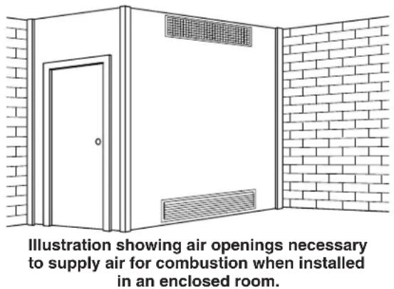
Properly sized vents are vital for the safe and efficient operation of a pressure washer installed in a confined space. When combustion and ventilation air are supplied from inside the building, each opening must have an area of one square inch for every 1,000 BTUH input. When combustion air is supplied from the outside, each opening must have an area of one square inch for every 2,000 BTUH for horizontal ducts and one square inch for every 4,000 BTUH for vertical ducts (refer to NFPA 54). See Figure 3.
The purpose of venting a gas pressure washer is to completely remove all products of combustion and to vent gasses to the outside air without condensation in the vent or spillage at the draft hood (except in cases of downdraft or poor stack conditions). To assure correct venting, use a strong, gas-tight insulated pipe with a cross section equal to that of the flue collar or draft hood outlet and of sufficient vertical height.
During vent installation, avoid sharp turns, long horizontal runs and improper pitches. Maintain proper support of vent connectors and joints, observe clearances from all combustibles and top the vent outlet with an approved cap.
INSTALLATION INSTRUCTIONS
Type "B", due to its temperature rating, can only be used with natural draft pressure washers. A "B" vent is designed for exhaust temperatures not to exceed 470^ F ( 245^ C).
All venting installations must conform to local codes. In the absence of local codes, refer to "National Fuel Gas Code" NFPA 54 and be constructed of materials approved by the Uniform Building Code.
Vents penetrating ceilings or walls should be double-wall approved appliance vents and should be one to two inches from combustibles. Vents passing through enclosed spaces and vents exposed to the weather should also be the double-wall type. Sometimes vents have to be built of such great length that they come apart at their joints under their own weight. These should be screwed together at the joints with sheet metal screws, usually three per joint. If the inspector indicates that the vent is too close to combustibles, it may be necessary to chisel away some of the combustible or route the vent pipe around the combustible. The cross-sectional area of any flue shall not be less that the cross-sectional area of the flue vent connection outlet of machine.
Figure 3: Ventilation
text_image
Illustration showing air openings necessary to supply air for combustion when installed in an enclosed room.Water Source:
The water source for the machine should be supplied by a 5/8" I.D. garden hose with a city water pressure of not less than 30 PSI. If the water supply is inadequate, or if the garden hose is kinked, the machine will run very rough and the burner will not fire.
Water Connection:
Connect the high pressure hose by pulling the coupler collar back and then inserting it onto the discharge nipple. Secure it by pushing the collar forward.
Attach the wand into the spray gun using teflon tape on the pipe threads to avoid leaks.
Inspection and Testing Gas Piping:
The building structure should not be weakened by installing the gas piping. The piping should not be supported by other piping, but should be firmly supported with gas hooks, straps, bands or hangers. Butt or lap welded pipe should not be run through or in an air duct or clothes chute.
Before turning gas under pressure into piping, all openings from which gas can escape should be closed. Immediately after turning on gas, the system should be checked for leaks. This can be done by watching the 1/2 cubic foot test dial for 5 minutes for any movement or by soaping each pipe connection and watching for bubbles. If a leak is found, make the necessary repairs and repeat the above test.
Defective pipes or fittings should be replaced and not repaired. Never use a flame or fire in any form to locate gas leaks — use a soap solution.
After the piping and meter have been checked completely, purge the system of air. DO NOT bleed the air inside an enclosed room.
During pressure testing of the system at test pressures in excess of 1/2 PSIG, the pressure washer and its individual shut-off valve must be disconnected from gas supply piping system or damage to the gas valve will occur.
text_image
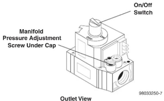
On/Off Switch Manifold Pressure Adjustment Screw Under Cap Outlet View 98033250-7Gas Pressure:
The ideal incoming gas pressure is 11 w.c.i (water column inches). Minimum is 9 w.c.i., maximum is 14 w.c.i. or 1/2 PSIG. The correct operating manifold pressure for natural gas is 2.8 w.c.i. The operating manifold pressure for propane gas is 7.5 w.c.i. By adjusting the gas valve pressure regulator between 3 and 4 w.c.i. a side range can be achieved for natural gas.
If the desired input rating cannot be obtained within the above manifold pressure adjusting range, then the next size larger or smaller burner orifice should be used.
INSTALLATION INSTRUCTIONS
The gas pressure coming out of the regulator and going to the burner ring has been factory set for elevations of 0 to 2000 ft. Altitudes greater than 2000 ft will require adjustments to the gas manifold pressures. Consult your local service dealer/distributor for high altitude adjustments. In Canada, certification for installation at altitudes over 4500 feet above sea level is the jurisdiction of local authorities. You should not readjust the burner ring gas pressure. If you replace your gas valve, you will need to adjust the new valve. Refer to your machine's specification plate for the correct pressure setting. Follow the installation and adjustment instructions provided with your replacement valve.
NOTE: Air for combustion and ventilation along with exhaust flue sizing must conform to methods outlined in current American Standard (ANSI-Z223.1) National Fuel Gas Code or National Standard of Canada CSA-149.1 and CSA-149.2 "Installation Code for Gas Burning Appliances".
OPERATION INSTRUCTIONS
Before Starting
- Read all manuals provided with this pressure washer. Become familiar with location and function of all operating and safety controls.
WARNING: Check hoses, fittings, wand, trigger gun and fuel connections daily for signs of wear, cracks and looseness, and replace as required.
- Connect water supply hose to the standard garden hose connector. The water faucet and supply hose must be capable of providing 6.0 GPM.
- This machine was factory built for natural gas/propane. See instructions under Fuel Supply.
- Check pump oil level.
- If detergents are to be used, only use detergents intended for pressure washers. Follow instructions on the detergent container.
IMPORTANT: Before installing pressure nozzle on initial start-up, turn on the water supply, start the pump by pressing the pump ON switch, and hold the wand trigger open until water appears at the end of the wand. Allow water to run from the end of the wand until clear to prevent the nozzle from clogging.
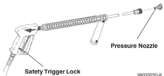
- Install the pressure nozzle on end of wand, refer to illustration below.
text_image
Safety Trigger Lock Pressure Nozzle 98033250-8IMPORTANT: The trigger gun provided with this pressure washer is equipped with a manual trigger lock to prevent accidental operation of the trigger gun, refer to figure above. The safety trigger lock should be used whenever the trigger gun is not in use.
IMPORTANT: On initial start-up or if maintenance has been performed on the burner assembly, it will be necessary to bleed the air from the gas line before the pilot will light.
- If you are running the machine for the first time, or have performed maintenance on the burner assembly, there will be air in the gas line. To bleed the air from the gas line run the pressure washer with pump and burner switches on and thermostat on highest setting. Squeeze the trigger of the trigger gun for 15 seconds. If the burner has not ignited, release the trigger for 5 seconds, then squeeze for 15 seconds. If the burner has not ignited after 10 tries, see the Troubleshooting Guide in this manual.
CAUTION: Have a qualified gas serviceman install and service your equipment.
DANGER: Never expose a spark or flame where there may be unburned gas present.
DANGER: Some gases are heavier than air and will spill out on the floor in the 2 to 3 minutes required for the safety pilot valve to close off gas supply. Therefore, always provide adequate space and ventilation around these units.
To Start
WARNING: Risk of injection or severe injury - Keep clear of nozzle - DO NOT direct discharge stream at persons - This machine is to be used only by qualified operators.
AVERTISSEMENT: RISQUE D'INJECTION ET DE BLESSURES GRAVES. SE TENIR À L'ÉCART DU JET. NE PAS DIRIGER LE JET DE SORTIE VERS D'AUTRES PERSONNES. CONFIER L'UTILISATION DE CE MATÉRIEL À UN OPÉRATEUR QUALIFIÉ.
WARNING: Wear eye, ear, hand, foot and skin protection at all times while operating pressure washer.
WARNING: Before changing pressure nozzle, engage manual trigger gun lock.
IMPORTANT: The water must be turned on before starting. Running the pump dry will cause damage and void warranty.
IMPORTANT: Do not allow the machine to run with trigger of the trigger gun released for more than 10 minutes at any one time or damage to pump may occur.
- Turn ON water supply.
- Turn ON gas supply.
- Hold wand firmly, release trigger of trigger gun and turn pump switch ON. Squeeze trigger of trigger gun and allow air to purge from system.
- If HOT water is desired, adjust the thermostat to the proper temperature and turn burner switch ON. Squeeze trigger of trigger gun. The pilot will automatically light, quickly followed by the firing of the burner ring. When the trigger of the trigger gun is released or when the thermostat temperature setting is reached, the burner will automatically turn off.
IMPORTANT: If ignition or flame failure is experienced, discontinue use of pressure washer at once. Turn off burner and shut off fuel supply. Have cause of failure corrected by an authorized service technician before use of pressure washer is continued.
OPERATION INSTRUCTIONS
To Clean
WARNING: Risk of injection or severe injury - Keep clear of nozzle - DO NOT direct discharge stream at persons - This machine is to be used only by qualified operators.
AVERTISSEMENT: RISQUE D'INJECTION ET DE BLESSURES GRAVES. SE TENIR À L'ÉCART DU JET. NE PAS DIRIGER LE JET DE SORTIE VERS D'AUTRES PERSONNES. CONFIER L'UTILISATION DE CE MATÉRIEL À UN OPÉRATEUR QUALIFIÉ.
- Insert detergent inlet line into container of mixed detergent. Open detergent ON/OFF valve. The detergent will be pulled automatically into the system. Allow detergent to reach end of wand before proceeding to step 3.
- Select pressure nozzle with spray pattern that matches your cleaning needs. Engage manual trigger lock and install selected nozzle.
-
Wash from the bottom to the top, using side to side motions. This washes away heavy dirt and allows the detergent to soak as you work toward the top.
-
Do not wash at a 90^ angle to the work (straight at it). This will allow water to splash back at you and reduces your cleaning power. Wash at a 30^ to 60^ angle to the work. This will allow the water to splash away from you and the water will wash the dirt away faster and easier.
- Use the width of the spray pattern to wash in a wide path. Overlap spray paths for complete coverage. Wash from side to side, using slow, steady motions.
- The nozzle should be 12" to 24" from work, closer for tough areas. Be careful on painted or delicate surfaces, the pressure may damage surface if nozzle is too close.
- Small parts should be washed in a basket and larger, lightweight parts should be clamped down so the pressure does not push them away.
- Close the detergent ON/OFF valve to permit rinse. Always rinse with cold water after using detergents. Rinse from the top to the bottom to prevent detergent from dripping onto a rinsed area. For the best results, contact your Hotsy dealer to help you select the best detergent for your application.
SHUTDOWN INSTRUCTIONS
To Stop
- If detergents were used, draw clear water through the detergent line to purge detergent. Failure to do so may clog detergent injector valve.
-
If burner was used, turn OFF burner switch and allow pump to run cold water through coil for several minutes.
-
Turn pump switch OFF.
- Turn water supply OFF.
- Squeeze trigger gun open to relieve system pressure.
- Depress gas control knob slightly and turn to OFF position.
- Turn off main shut-off valve on gas supply.
STORAGE INSTRUCTIONS
DANGER: Do not store flammable liquids (gasoline, diesel fuel, petroleum, solvents, etc.) near pressure washer, or in non-ventilated areas.
IMPORTANT: Machine must be stored indoors.
- Protect from freezing by storing in a heated area, or by flushing the system with antifreeze (use an automotive engine antifreeze or windshield washer solvent to antifreeze). To flush the system fill the float tank with antifreeze and remove pressure nozzle from wand. Start the machine and allow it to run until antifreeze runs from the end of the wand. Place wand into float tank and circulate the solution
through system for several minutes. Open and close the trigger gun several times to circulate antifreeze through the unloader valve system. Also draw antifreeze through the detergent inlet line to antifreeze the detergent system. For added protection after antifreezing, disconnect the pressure hose from machine and remove the coil drain plug (refer to Component Identification illustration for location). After coil has drained, replace pressure hose and coil drain plug. If the pressure washer is not to be used for an extended length of time, it is recommended that the system be flushed with antifreeze for rust protection.
MAINTENANCE
WARNING: Unauthorized machine modification or use of non-approved replacement parts may cause personal injury and/or property damage and will void the manufacturer warranty.
Pump
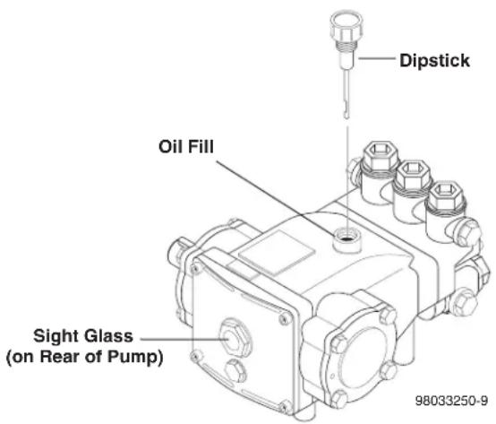
Use Hotsy Pump Oil (8.914-527.0) for pump crankcase. Crankcase must be filled to the full mark on the dipstick or to center of sight glass window found on the rear of the pump. During the break-in-period, make sure the oil is changed after the first 25 hours of operation. After that, replace oil every 3 months or 300 hours of operation, whichever comes first.
text_image
Dipstick Oil Fill Sight Glass (on Rear of Pump) 98033250-9Proper Pump Care:
- Do not pump acids.
• Do not allow pump to run dry. - Winterize if storing in freezing temperatures; refer to Storage for details.
- Use a water softener on the water system if known to be high in mineral content.
- Use only high quality detergents and follow manufacturer's mix recommendations.
-
Flush the system with clear water immediately after using detergent solutions.
-
Clean filter screen on detergent inlet line periodically.
- Flush the pressure washer system with antifreeze if storing for an extended period of time; refer to Storage for details.
Pump Motor
On a yearly basis, oil pump motor per instructions on motor nameplate.
NOTE: Some motors may be equipped with permanently lubricated bearings and will not require additional lubrication.
Gas Burner
It is recommended that the gas burner be serviced yearly or as needed. Contact your local service center.
Relief Valve
WARNING: The relief valve on this pressure washer has been factory set and sealed and is a field nonadjustable part. Tampering with the factory setting may cause personal injury and/or property damage, and will void the manufacturer warranty.
Unloader Valve
WARNING: The unloader valve on this pressure washer has been factory set and sealed and is a field nonadjustable part. Tampering with the factory setting may cause personal injury and/or property damage, and will void the manufacturer warranty.
Heating Coil
Coil Descaling: In hard water areas, scale buildup within the heating coil will occur. Scale deposits will decrease the water temperature rise and may eventually clog the heating coil. Contact your local service center when descaling is needed.
Coil Desooting: Poor grades of fuel oil or inadequate combustion air will cause heavy soot buildup on the outside surface of the heating coil. These deposits will insulate the coil. This will restrict the air flow through the coil, further aggravating the soot buildup. Contact your local service center when desooting is needed.
TROUBLESHOOTING
| SYMPTOM POSSIBLE CAUSES CORRECTIVE ACTION | ||
| PRESSURE WASHER WILL NOT RUN | Pump switch in OFF position Place | switch in ON position. |
| Power supply disconnected Conne | ct power supply. | |
| Fuse blown or circuit breaker tripped in electrical supply line | Replace fuse or reset circuit breaker.Use only circuits of adequate capacity. | |
| Motor circuit overload tripped Allow | sufficient time for motor to cool down.Place pump switch in ON position. | |
| PRESSURE WASHER RUNS BUT WON'T SPRAY | Trigger of trigger gun released Squeeze trigger. | |
| Water supply not turned on Open water supply valve. | ||
| Clogged pressure nozzle Clean pressure nozzle opening. | ||
| Inlet water screen clogged Check screen and clean if necessary. | ||
| Pump sucking air | Fill the detergent container and check for loose hose clamps or fittings. | |
| LOW SPRAY PRESSURE AT NOZZLE | Inadequate water supply | Fully open faucet. Check for kinked or damaged hose. Use 5/8" minimum hose.Check for debris clogging inlet screen. |
| Partially clogged or damaged pressure nozzle | Clean or replace. | |
| Air being drawn through detergent inlet line | Refill detergent container. Ensure that pick-up screen is fully immersed. | |
| UNEVEN SPRAY PATTERN | Partially clogged or damaged pressure nozzle | Clean or replace. |
| PRESSURE WASHER WILL NOT PRODUCE HOT WATER | Burner switch in OFF position | Place switch in ON position. |
| Gas valve switch in OFF position | Place switch in ON position. | |
| Inadequate fuel supply | Check fuel supply. | |
| Pump switch turned off | Pump must be running before burner will light. | |
TROUBLESHOOTING
| SYMPTOM POSSIBLE CAUSES CORRECTIVE ACTION | ||
| PRESSURE WASHER WILL NOT PRODUCE HOT WATER (Continued) | Inadequate water supply Fully open | faucet. Check for kinked or damaged hose. Use 5/8" minimum hose. Check for debris clogging inlet screen. |
| Trigger of trigger gun released Sque | eze trigger. Water must be spraying for burner to light. | |
| Thermostat set too low, or defective | Raise thermostat setting. Replace if defective. | |
| Manual gas valve not open Turn ON | gas valve. | |
| Defective gas valve Replace gas valve. | ||
| POOR OR NO DETERGENT FLOW | Inadequate detergent supply Refill d | detergent container. Ensure that pick-up screen is fully immersed. |
| Detergent screen or hose clogged C | lean. Always start with a clean detergent container. | |
| Clogged detergent injector check valve | Clean check valve at detergent injector. | |
| POOR CLEANING | Improper detergent concentration or mixing | Mix detergent per manufacturer's instruc-tions. Ensure that powdered detergents are fully dissolved. |
| Wrong detergent for the application | Select appropriate detergent. | |
| Rinsing with hot water A final rinse w | with cold water will reduce water spotting. | |
| Detergent valve not opening | Check that handle or knob is not slipping on shaft. | |
| UNLOADER CYCLES WHEN TRIGGER GUN IS OPENED OR CLOSED | Air in system | Open and close trigger gun several times. |
| Unloader defective | Replace if defective. | |
| Water leak between unloader valve and trigger gun | Check fittings, hose and trigger gun for leaks. Repair or replace. | |
| BURNER SMOKES OR HAS OBNOXIOUS ODOR | Stack restriction | See Venting under Installation. |
| PRESSURE RELIEF VALVE LEAKING | Excessive pressure due to defective unloader valve | Replace unloader valve. |
| Defective relief valve | Replace relief valve. | |
| Dirty relief valve | Clean relief valve seat | |
BURNER TROUBLESHOOTING
| PROBLEM POSSIBLE CAUSE SOLUTION | ||
| HAVE PILOT FLAME, MAIN BURNER WILL NOT TURN ON | Faulty main valve coil in the gas valve | Set test meter to 24 volt scale. |
| Faulty ignitor/sensor and/or its wiring | With pilot flame on ignitor/sensor, probe terminals MV and MV/PV on the ignition control unit. If you read 24 volts here, but not at the gas valve, there is a loose wiring connection. Repair or replace as needed. | |
| Ground wire not attached to machine chassis | If you do read 24 volts at MV and MV/PV and the pilot flame is impinging on the ignitor/sensor rod, the problems may be: | |
| Faulty ignition control unit a. Faulty ignition/sensor and/or its wiring. | ||
| SHORT-CYCLING OF MAIN BURNER. MAIN BURNER TURNS OFF BEFORE THE BURNER SWITCH OR FLOW SWITCH IS TURNED OFF | Draft condition pulls flame from ignitor/sensor rod. | Check the thermostat by bypassing at terminals P1 & 1. |
| Set thermostat high. With main burner on, observe the pilot flame impingement on the ignitor/sensor. | ||
| Faulty thermostat or water temperature is too high | If pilot flame is small and draft condition pulls flame from ignitor sensor rod, the burner will turn off and then on again. a. Adjust pilot flame higher or clean pilot oriface. b. Bend ignitor/sensor rod closer to pilot flame. | |
| If flame impingement on the ignitor/sensor is stable and the system short-cycles, check the limit switch. | ||
| Set test meter to 110 volt scale; a. When the system cycles off, probe the switch terminals of the limit switch. b. If you read 24V across the switch terminals the limit switch is open. Replace the limit switch. | ||
| A pilot flame set too high will also cause burner to short cycle. Pilot flame lifts over ignitor/sensor. | ||
BURNER TROUBLESHOOTING
| PROBLEM POSSIBLE CAUSE SOLUTION | ||
| FLOW & BURNERSWITCH ON;NO SPARK,NO PILOT GAS | A. No main powerB. Faulty transformerC. Faulty burner & flow switchD. Faulty ignition control unit | With power switch on, open trigger on spray gun and set your test meter to the 24 volt scale. Probe terminals 24V and 24V(GND). If you do not read 24 volts, the problem is not the ignition system. Perform normal system checks of main power, transformer, thermostat and the limit control. If you do read 24 volts at TH and GND, the problem is in the ignition system. Check for loose or defective wiring. If wiring is good, replace the ignition control unit. |
| HAVE SPARK,NO PILOTGAS FLOW | Main gas supply turned off Set | Test meter to 24 volt scale. |
| 1. Be sure main gas valve (gas cock or selector arm) is turned on. | ||
| 2. With gas on and system sparking, probe terminals PV and 24V(GND). If pilot gas does not flow with 24 volts at these terminals, replace gas valve. | ||
| 3. Probe terminals PV and MV/PV. If 24 volts not present, replace ignition control box. | ||
| HAVE PILOTGAS, NO SPARK | A. Defective ignitor/sensor and or its wiring | Set test meter to ohm scale. |
| 1. Disconnect the wire from the IGN terminal on the ignition control unit. | ||
| B. Faulty ignition control unit 2. | Touch one meter probe to the tip of the ignitor/sensor rod in the pilot. Touch the other probe to the quick connect at the other end of ignitor/sensor wire. | |
| 3. If you have continuity from the tip of the ignitor/sensor rod to the connector and no spark, replace the ignition control unit. | ||
| 4. If you do not have continuity through wire and the ignitor/sensor, check for a loose wire connection in the wire. Repair as needed. | ||
| 5. Check to see if spark shorts to burner ring through a cut in the ignitor wire. | ||
IMPORTANT
If the pressure washer demonstrates other symptoms or the corrective actions listed do not correct the problem, contact the local authorized Hotsy Service Center. The Hotsy Service Center can be identified by visiting www.hotsy.com.
When ordering from your dealer, please provide the following:
Model Number: ____ Release: ____
Machine Serial Number: ____
Component Part Number: ____
Description: ____
GAS-FIRED SERIES OPTIONAL EQUIPMENT
835526 Draft Diverter, 8"

HOTSY LIMITED NEW PRODUCT WARRANTY
PRESSURE WASHERS
WHAT THIS WARRANTY COVERS
All Hotsy pressure washers are warranted by Hotsy to the original purchaser to be free from defects in materials and workmanship under normal use, for the periods specified below. This Limited Warranty is subject to the exclusions shown below, is calculated from the date of the original purchase, and applies to the original components only. Any parts replaced under this warranty will assume the remainder of the part's warranty period.
SEVEN YEAR PARTS AND ONE YEAR LABOR WARRANTY:
Components manufactured by Hotsy, such as frames, handles, top and bottom wraps, float tanks, fuel tanks, belt guards, and internal components on the oil-end of HOTSY manufactured pumps. General, AR, Liberty, Comet and swash and wobble plate pumps have a one year warranty. Heating coils have a five year warranty from date of original machine purchase.
ONE YEAR PARTS AND ONE YEAR LABOR WARRANTY:
All other components, excluding normal wear items as described below, will be warranted for one year on parts and labor. Parts and labor warranty on these parts will be for one year regardless of the duration of the original component manufacturer's part warranty.
WARRANTY PROVIDED BY OTHER MANUFACTURERS:
Motors, generators, and engines, which are warranted by their respective manufacturers, are serviced through these manufacturers' local authorized service centers. Hotsy is not authorized and has no responsibility to provide warranty service for such components.
WHAT THIS WARRANTY DOES NOT COVER
This warranty does not cover the following items:
- Normal wear items, such as nozzles, spray guns, discharge hoses, wands, quick couplers, seals, filters, gaskets, O-rings, packings, pistons, pump valve assemblies, strainers, belts, brushes, rupture disks, fuses, pump protectors.
- Damage or malfunctions resulting from accidents, abuse, modifications, alterations, incorrect installation, improper servicing, failure to follow manufacturer's maintenance instructions, or use of the equipment beyond its stated usage specifications as contained in the operator's manual.
- Damage due to freezing, chemical deterioration, scale build up, rust, corrosion, or thermal expansion.
- Damage to components from fluctuations in electrical or water supply.
- Normal maintenance service, including adjustments, fuel system cleaning, and clearing of obstructions.
- Transportation to service center, field labor charges, or freight damage.
WHAT YOU MUST DO TO OBTAIN WARRANTY SERVICE
In order to obtain warranty service on items warranted by Hotsy, you must return the product to your Authorized Hotsy Distributor, freight prepaid, with proof of purchase, within the applicable warranty period. If the product is permanently installed, you must notify your Authorized Hotsy Distributor of the defect. Your Authorized Hotsy Distributor will file a claim with Hotsy, who must subsequently verify the defect. In most cases, the part must be returned to Hotsy freight prepaid with the claim. For warranty service on components warranted by other manufacturer's, your Authorized Hotsy Distributor can help you obtain warranty service through these manufacturers' local authorized service centers.
LIMITATION OF LIABILITY
Hotsy's liability for special, incidental, or consequential damages is expressly disclaimed. In no event shall Hotsy's liability exceed the purchase price of the product in question. Hotsy makes every effort to ensure that all illustrations and specifications are correct, however, these do not imply a warranty that the product is merchantable or fit for a particular purpose, or that the product will actually conform to the illustrations and specifications. Our obligation under this warranty is expressly limited at our option to the replacement or repair at a service facility or factory designated by us, of such part or parts as inspection shall disclose to have neen defective. THE WARRANTY CONTAINED HEREIN IS IN LIEU OF ALL OTHER WARRANTIES, EXPRESS OR IMPLIED, INCLUDING ANY IMPLIED WARRANTY OF MERCANTABILITY OR FITNESS FOR A PARTICULAR PURPOSE ARE EXPRESSLY LIMITED TO THE DURATION OF THIS WRITTEN WARRANTY. Hotsy does not authorize any other party, including authorized Hotsy Distributors, to make any representation or promise on behalf of Hotsy, or to modify the terms, conditions, or limitations in any way. It is the buyer's responsibility to ensure that the installation and use of Hotsy products conforms to local codes. While Hotsy attempts to assure that its products meet national codes, it cannot be responsible for how the customer chooses to use or install the product. Some states do not allow limitations on how long an implied warranty lasts or the exclusion or limitation of incidental or consequential damages, so the above limitation or exclusion may not apply to you. This warranty gives you specific legal rights and you may also have other rights which vary from state to state.
HOTSY
www.hotsy.com
If you are looking for replacement parts for your Hotsy, please contact your local dealer. You can find a dealer by calling Hotsy at 800-525-1976 or by visiting www.hotsy.com.
If you need service on your pressure washer, contact your local Hotsy dealer or visit www.Hotsy.com. Smart phone users scan the code below to link directly to the Service Request page.