
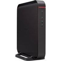
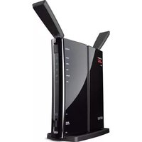
WBR-G54 - Router BUFFALO - Free user manual and instructions
Find the device manual for free WBR-G54 BUFFALO in PDF.


| Product Type | Wireless Router (Wi-Fi G) |
| Brand | Buffalo |
| Model | WBR-G54 |
| Wireless Standard | IEEE 802.11g/b |
| Maximum Wireless Speed | 54 Mbps |
| Frequency Band | 2.4 GHz |
| Number of WAN Ports | 1 x 10/100 Ethernet |
| Number of LAN Ports | 4 x 10/100 Ethernet |
| Security Features | WEP, WPA, WPA2, MAC filtering, SPI firewall |
| Power Supply | External AC adapter, 5V DC 2A |
| Dimensions (W x D x H) | 150 mm x 110 mm x 35 mm |
| Weight | 0.4 kg |
| Management | Web-based GUI, DHCP, NAT, VPN pass-through |
| Antenna Type | 2 external detachable antennas (reverse SMA) |
| Antenna Gain | 2 dBi each |
| Operating Temperature | 0°C to 40°C |
| Storage Temperature | -20°C to 60°C |
| Humidity | 20% to 80% (non-condensing) |
| Certifications | FCC, CE |
| Package Contents | Router, power adapter, Ethernet cable, manual, CD |
Frequently Asked Questions - WBR-G54 BUFFALO
User questions about WBR-G54 BUFFALO
0 question about this device. Answer the ones you know or ask your own.
Ask a new question about this device
Download the instructions for your Router in PDF format for free! Find your manual WBR-G54 - BUFFALO and take your electronic device back in hand. On this page are published all the documents necessary for the use of your device. WBR-G54 by BUFFALO.
USER MANUAL WBR-G54 BUFFALO
wireless broadband router base station-g
WBR-G54
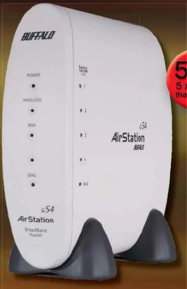
54Mbps
5 x Faster than 802.11b
Fast,
secure
networking made
EASY!


Table of Contents
INTRODUCTION....4
I.1 AirStation Broadband Router Base Station (WBR-G54) 4
1.2 AirStation Wireless Network Features 4
1.3 Home Networking 5
1.4 SOHO/SMB Networking 5
1.5 System Requirements 5
1.6 AirStation Package Contents 5
1.7 Product Views 6
1.8 About the AirStation CD 6
INSTALLATION/SETUP 7
2.1 Introduction 7
2.2 Hardware Installation 7
STANDARD SETTINGS 8
3.1 Introduction 8
3.2 Setup Preparation 8
3.3 Setup Overview 8
3.4 Open the Setup Screen 8
3.5 Enter ISP Information 9
3.5.1 DSL Button 9
3.5.2 CATV Button 9
3.5.3 Line Test Tab 10
3.5.4 Security Tab 10
3.5.5 Application Tab 11
ADVANCED SETTINGS ...... II
4.1 LAN Setting.... 11
4.1.1 Wireless.... 11
4.1.2 Wireless Security 12
4.1.3 LAN Port 14
4.1.4 DHCP Server.... 14
4.1.5 Wireless LAN Computer Limitation 15
4.1.6 WDS 15
4.2.1 WAN Port 16
4.2.2 Network WAN 17
4.3 Network Setting 17
4.3.1 Routing Setup.... 17
4.3.2 Address Translation 18
4.3.3 Packet Filter 18
4.3.4 Intrusion Detector.... 20
4.3.5 UPnP 20
4.4 Management (Network Diagnosis Settings) 21
4.4.1 System Information 20
4.4.2 Name and Password 21
4.4.3 Time setup 21
4.4.4 Transfer Packet Condition 22
4.4.5 Client Monitor 22
4.4.6 Ping Test 22
4.4.7 Log Information 22
4.4.8 Syslog Transmitting.... 23
4.4.9 Save/Restore Settings.... 23
4.4.10 Initialization/Reboot. 23
4.4.11 Firmware Update 23
4.4.12 Logout 23
SPECIFICATIONS 24
TROUBLESHOOTING 26
GLOSSARY....28
FCC INFORMATION....29
WARRANTY INFORMATION....30
CONTACT INFORMATION....30
1
Introduction
I.I AirStation 54Mbps Wireless Broadband Router Base Station
(WBR-G54)
Welcome to AirStation, the easy way to fast wireless networking. This manual introduces you to the high-speed AirStation 54Mbps Wireless Broadband Router Base Station and will help you connect to your broadband internet connection quickly.
The high-speed AirStation Broadband Router Base Station (Access Point or AP), is a wireless 4-port router small/medium business (SMB) network device that complies with the 2.4GHz IEEE 802..11g standard as well as the IEEE 802.11b standard specification on wireless LANs. IEEE 802.11g technology features longer range than IEEE 802.11a and greater bandwidth with data rates up to 54 Mbps. The AirStation supports enhanced built-in NAT firewall functions and is used as a multi-functional link between wired and wireless LAN computers.
Summary of the AirStation WBR-G54 features:
- Wi-Fi™ (Wireless Fidelity) certified by the Wi-Fi Alliance as an 802.11b device. AirStation will communicate with other IEEE 802.11b/Wi-Fi compliant wireless LAN products.
• Support for Wi-Fi Protected Access™ (WPA), AES, 802.1x, TKIP and WEP.
• Automatic Transmit Rate Select mechanism transmits at speeds of 24, 12, 11, 5.5, 2 and 1 Mbps.
• Supports turbo mode of 36, 48 and up to 54 Mbps.
• DHCP client/server function.
• Auto roaming, supports seamless roaming over multiple channels.
• Auto VPN setup, for secure communications. - Packet Filtering for eliminating unwanted communications.
- SOHO/SMB routing and firewall functions provide a safer private networking environment, including MS NetMeeting and MSN-Messenger.
• Additional Firewall Functions - DMZ, intrusion detection and notification - Syslog transmits some or all system activities to a central Syslog server.
• Extended range, with optional add-on antennas. - Auto Media Dependent Interface/Crossover (MDI/X) port, allows connection by standard and crossover CAT5 cables.
• Supports Universal Plug and Play (UPnP).
1.2 AirStation Wireless Network Features
• Enhanced security features:
- Firewall and DMZ zone functions to prevent unknown intruders.
- Intrusion Detector Firewall (NAT) with a pop-up or email alert warning unwanted attacks.
- Dynamic packet filtering function prevents specified ports being open to WAN during periods of non use.
- WPA, AES, 802.1x, TKIP and WEP. WEP for protecting data.
- VPN (IPSec, PPTP and L2TP) pass-through
- Packet monitoring and filtering by MAC address, IP address and port.
- PPPoE support
- Buffalo's easy web interface configuration
- Broadband router static and dynamic routing methods between WAN and LAN based on updated routing tables. An economical way to bridge multiple networks.
- Optional external antennas for boosting range and signal quality.
- Improved resistance to environmental conditions.
1.3 Home Networking
For the future home entertainment applications that carry hard drives for storing hundreds of titles, IEEE 802.11g can transmit three channels of CD-quality voice, or DVD-quality video to every room in the home simultaneously. Buffalo AirStation wireless access points enable sharing broadband by simply connecting the AirStation to a DSL or CATV modem to:
• Share fi les and printers
• Access and share the Internet
• Share home entertainment system
I.4 SOHO/SMB Networking
With high-speed DSL or CATV connections readily available, many users can work effectively from a home office, connected securely to a corporate network. Buffalo's solutions are ideal for home networks that require secure, high-speed access to the corporate LAN. Tools that play an integral part in Buffalo's solutions include VPN connectivity for secure access to corporate resources, which enable the remote employee to handle information from clients or coworkers as if they were in the office. IEEE 802.11g technology enables anticipated data intensive applications such as high security communication and VoIP. Connect the Buffalo AirStation Broadband router AP to a CATV or DSL modem in order to:
• Share broadband access
• Share fi les and printers
- Bridge between multiple networks and multiple computer platforms
- Provide easy and secure access to home or company networks from remote locations
Figure 1.4 SOHO/SMB Networking
![graph LR A["Internet"] -->|Cable/DSL Modem| B["AirStation"] B --> C["Device 1"] B --> D["Device 2"] B --> E["Device 3"] B --> F["Device 4"]](/content/2026/05/781795/images/6efe3496c51fe808c6325c735d9e1ecbc33da419b2ed4f001635558107bca2d0.jpg)
1.5 System Requirements
- Broadband (High-Speed) Internet connection or existing Local area connection
- Any Wi-Fi (wireless) compatible computer with a Web Browser Internet Explorer or Netscape 4.5 or later. (Safari 1.0 is supported with Macintosh OS X.2)
Buffalo AirStation software is for:
Windows® 98SE, 2000, Me and XP
1.6 AirStation WBR-G54 Package Contents
The AirStation WBR-G54 package consists of the following items.
I. WBR-G54 Base Station
2. AC adapter and power cable
3. CAT5 LAN cable
4. Utility CD with Manual
5. Warranty Statement
1.7 Product Views


-
Power LED 7. 10/100M 4-port LAN switch
-
Wireless LED
-
WAN port
-
WAN LED 9. Power port
-
LAN LEDs 10. LAN MAC Address
-
DIAG LED 11.WAN MAC Address
-
INIT Button 12. External Antenna connector (MC connector)
1.8 About the AirStation CD
The AirStation does not require any software to be installed on your computer for configuration. The AirStation CD contains client drivers for Buffalo Wireless Adapters (i.e. Notebook Adapter and Desktop PCI Adapter) and the AirStation Client Manager which can be used to connect the client adapters to the AirStation in order to access the web configuration screen of the AirStation.
The WBR-G54 CD contains the AirStation utility, AirNavigator. Buffalo Technology USA does not recommend the use of AirNavigator with the WBR-G54 or any other Buffalo AirStation G54 product.
Prior to copying or installing any software, please read the Software License Agreement "license.txt", located in the root folder of the CD. By installing, copying or using the AirStation software, you are consenting to the terms of this agreement. If you do not agree to all of the terms of the Software License Agreement, do not download, copy or install the AirStation software.
It is the policy of Buffalo Technology to improve products as new technology, components, software and firmware become available.
Before you proceed with the installation of this product, please consult the AirStation wireless website (http://www.buffalotech.com/wireless/) to download and install the latest software for your product.
Follow these simple steps to connect and the AirStation to your Broadband Internet connection allowing you to com-
2
Installation/Setup
bine and share wired and wireless computers and printers with the high-speed internet connection
![graph TD A["电脑"] -->|数据流| B["服务器"] C["电脑"] -->|数据流| B D["电脑"] -->|数据流| B E["电脑"] -->|数据流| B B -->|无线连接| F["电脑"] B -->|无线连接| G["电脑"]](/content/2026/05/781795/images/c004cc38f9854546c5d1a0b2d5fd2503dc0734ed78328c92649acb19e58979ae.jpg)
- Power down the cable or DSL modem and the computer which will be used to configure the AirStation router.
- Plug the cable or DSL's LAN Ethernet cable into the AirStation's WAN port. Initially, you may need to unplug this cable from your computer, hub or other router.
- Plug the provided Ethernet cable into a LAN port on the AirStation and plug the other end into your computer Ethernet adapter's (NIC) port. If you plan to initially configure the AirStation via a wireless connection, (not recommended), you may skip this step.
- Power on your cable or DSL modem, wait one full minute, Power on the AirStation router, wait another full minute and then power on the computer which will be used to configure the AirStation. If the red DIAG light on the AirStation is lit or flashing after several minutes of being powered on, please consult Buffalo Technical Support.
3
Standard Settings
3.1 Introduction
Configuring the AirStation using a standard web browser requires basic wireless configuration knowledge. Setup includes manual wireless configuration and basic administrative management.
3.2 Setup Preparation
Make note of the AirStation's wired MAC address (found on the back of the WBR-G54). It is also recommended you record any other broadband ISP information such as global IP address, subnet mask address, default gateway address, DNS server address and PPPoE parameters.
3.3 Setup Overview
Buffalo recommends using a wired connection, meaning your computer is physically connected to the AirStation with an CAT5 straight cable plugged into one of the four LAN ports. This type of setup will eliminate possible setup problems due to any issues with the wireless adapter on the computer being used to configure the AirStation.
A Web browser version 4.5 or later can be used to configure the AirStation.
The WBR-G54 CD contains the Client Manager program. The Client Manager is used with a Buffalo Wireless Client Adapter (CardBus, USB or PCI) to associate, setup and configure the AirStation and for monitoring the wireless signal between the AirStation and Buffalo client.
Client Manager is currently not recommended for initial configuration of the AirStation. Please refer to the Buffalo website for the latest information and software for the AirStation.
Advanced settings for security, filtering and other features will be explained in later sections.
3.4 Open the Setup Screen
- Connect the WBR-G54 according to the wiring instructions in Section 2.
• The WBR-G54 has a default LAN IP address of 192.168.11.1 and Subnet Mask of 255.255.255.0.
Note: The computer used to configure the AirStation can be set to obtain an IP address automatically using a DHCP server settings. The Quick Setup Guide enclosed with the product contains detailed instructions on how to configure your computer for initial configuration.
Figure 3.4
Initial Settings
Login
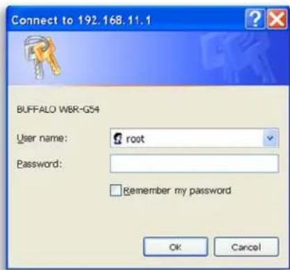
On the computer used to configure the AirStation, launch a Web Browser 4.5 or later.
- Enter 192.168.11.1 into the URL field.
- A window will open prompting you to enter a User ID and Password
Enter "root" as the User ID and leave the password field blank.
■ Note: These are the factory default settings
Figure 3.5
Initial
Settings
Screen
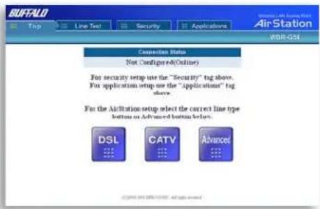
Fig ure 3.5.1
Initial DSL
button
Screen

Figure 3.5.1a Manual DSL IP Settings Screen

Fig ure 3.5.1b
DSL PPPoE
Settings
Screen

Figure 3.5.2
Initial CATV
Settings
Screen

3.5 Enter ISP information
- Click the appropriate button to select the type of broadband access. (Users more experienced in networking may choose to select the Advanced button and skip to Section 4.)
- For supplementary tools, use the tabs along the top of the screen.
3.5.1 DSL Button
Select the appropriate connection method.
Automatic IP Assignment by ISP
- The DHCP server of the ISP assigns an IP address automatically.
Enter IP address manually
- Enter the IP address given by the ISP.
PPPoE Connection
- Enter the PPPoE information provided by the ISP.
3.5.2 CATV Button
Select the appropriate connection method.
Automatic IP Assignment by ISP
- The DHCP server of the ISP assigns an IP address automatically.

Enter IP address manually - Enter the IP address given by the ISP.

The IP address is acquired au to mat i cal ly but DNS server address is entered manually - Enter the DNS server in for ma tion manually even though the IP address is acquired automatically.

3.5.3 Line Test Tab
Tests the connection to the Internet.

3.5.4 Security Tab
The Security Tab offers three Simple Security Settings. Follow the in structures in each screen to enter WEP keys, MAC Address Filtering and the degree of fi rewall security for the AirStation.

Fig ure 3.5.4a Simple WEP Setup

Figure 3.5.4b Simple MAC Address Filter

Figure 3.5.4c Simple Security Setup
The Application Tab offers setup for special applications such as games, MS NetMeeting and MSN Messenger. Follow the instructions in each screen.

Fig ure 3.5.5a Web Gaming Setup
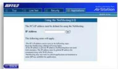
Fig ure 3.5.4b NetMeeting Setup
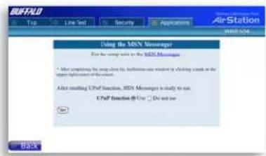
Fig ure 3.5.4c MSN Messenger Setup

Advanced Settings
Although your AirStation will function fine using only the settings from Section 3, you may wish to explore more advanced options. This chapter explains each parameter in the Advanced button.
Click the Top tab and click the Advanced button.
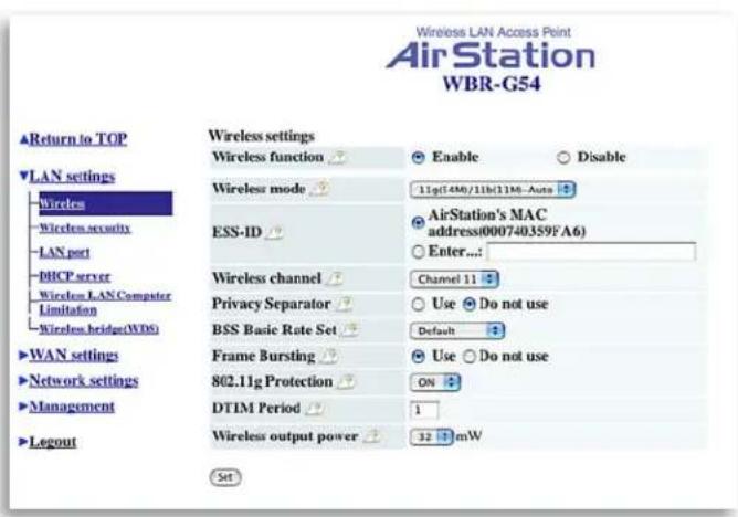
Figure 4.1.1 Wireless Settings
4.1 LAN Setting
Set up LAN connections.
4.1.1 Wireless
Wireless Function - Enable or disable wireless LAN computer communication.
Wireless Mode - Select one of the following:
- 11g(54M)-Turbo - Boosts 11g devices to turbo 54Mbps mode. 11b devices cannot connect.
- 11g(54M)/11b(11M)-Auto - Allows communication of 11g and 11b devices. Communication speed will drop to 11Mbps when 11b devices are connected. (Default setting)
- IIb(IIIM) Wi-Fi - Uses only the IEEE 802.IIb(IIMbps WiFi compatible) standard.
ESS-ID (SSID) - Allows administrator to alter the ESS-ID of the AirStation. To communicate with a specific AP only, the AP's ESS-ID must be entered in the client computer. The client computer looks for the specific AP (or ESS-ID) for wireless communication. Use up to 32 alphanumeric characters for the ESS-ID (case sensitive).
Note: Roaming - When multiple AirStations have an identical ESS-ID, WEP, (and channel in WDS mode), client computers may Roam between the AirStations.
Wireless Channel - Select the channel used for wireless communication. There are 11 overlapping channels. Channels 1, 6 and 11 are non-overlapping.
If there are multiple APs in close proximity using the same channel, there may be interference. In this case, change to a non-overlapping channel.
■ Note: This parameter is automatically set in the client computer.
Privacy Separator - Enable or disable communication between wireless clients. If you choose to use this feature, every wireless client that is associated to the AirStation will not be able to communicate with any other wireless clients.
■ Note: If this function is used, wired clients can still communicate with wireless clients.
BSS (Basic Service Set) Basic Rate Set - The transmission data rate between devices. If one device supports 2Mbps only, the data rate for the entire network should be limited to 2Mbps ("Default" selection). Otherwise, use 11Mbps Max ("All" selection).
Frame Bursting - This function increases 802.11g communication throughput by transferring packets more efficiently. The following conditions affect this function:
- The wireless LAN client adapter must support Frame Bursting (and it must be enabled).
- When several wireless clients use the Frame Bursting feature, throughput might not increase.
802.11g Protection - When this function is enabled, 802.11g protection mechanisms are started. These mechanisms should be used when mixed 11b and 11g clients use the wireless network. If only 11b or only 11g clients use the wireless network, then this function should be turned off. This function enables CTS (Clear-to-send).
DTIM Period - An access point transmits beacon signals to nearby clients at a preset interval. This parameter sets the beacon transmission interval time (1-255 sec.). Selection of a larger number may conserve energy for the client computer (when client power management is enabled), but may delay wireless communication. The default value of 1 is recommended.
Note: Setting the DTIM period too high can cause detrimental effects to the network and power saving clients may lose their connections entirely.
Wireless output power - Configure output power of AirStation. Decrease wireless output power to shrink the wireless communication range. The default setting of 32mW is recommended.
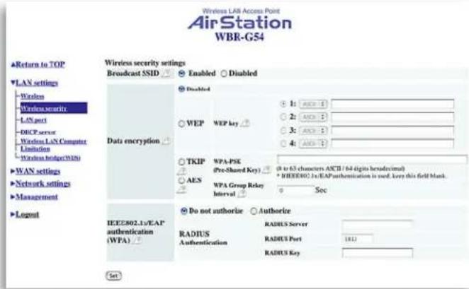
Figure 4.1.2 Wireless Security Settings
4.1.2 Wireless Security
Broadcast SSID - Enable or Disable the SSID (ESS-ID) from being broadcast. If enabled, the AirStation will not be found unless the specific AirStation's SSID is entered in the client computer.
Data Encryption - Disable to have no password protection of the wireless data.
Select encryption type of wireless data communication.
• Disabled - Disable data encryption.
- WEP - Uses WEP encryption. Encryption key should be entered.
- TKIP - Uses TKIP (Temporal Key Integrity Protocol) for data encryption.
- AES - Uses AES (Advanced Encryption Standard) for data encryption.
The encryption key is renewed every "Re-key interval" when "TKIP" or "AES" is selected.
Either "Disabled" or "WEP" can be selected if Network Authentication is disabled or if 802.1x is selected. Either "TKIP" or "AES" can be selected if the WPA configuration setting is "WPA" or "WPA-PSK".
WEP - When the WEP (Wired Equivalent Protection) encryption standard is implemented into a wireless network, a WEP key is used between the client and access point to successfully encrypt, transmit and decrypt data. For this reason, the same WEP key must be used for communication between the client and the AirStation. An access point and client may both carry multiple WEP keys. It is necessary for not only the WEP keys to match, but also the WEP key's order. If a wireless client cannot support multiple WEP keys, the AirStations must be configured to transmit key number 1 for a connection to take place.
Examples of WEP key:
64-bit ASCII: 5 digits of alphanumeric characters, "ab34Y"
128-bit ASCII: 13 digits of alphanumeric characters, "123456abcdef7"
■ Note: ASCII WEP keys are case sensitive.
64-bit HEX: 10 digits, using characters 0-9 and a-f, "00234ABCDE"
128-bit HEX: 26 digits, using characters 0-9 and a-f, "20123456789abcdeabcdeabcde"
TKIP - TKIP (Temporal Key Integrity Protocol) is a WEP expanded encryption technique. TKIP has greatly improved WEP's weaknesses by rotating secret keys between every packet. TKIP uses WPA-PSK (pre-Shared Key). Characteristics:
- The Initialization Vector is expanded from 24-bits to 48-bits.
- The Initialization Vector is randomized.
- Uses a different RC4 key for every packet.
AES - AES (Advanced Encryption Standard) is a next generation encryption technique discussed by the IEEE 802.11 committee. TKIP improves WEP's weakness, however AES also changes encryption method away from the weaker RC4 style. Throughput decreases 10 to 20 percent when TKIP software encoding is used. AES uses a hardware coprocessor and performance does not decrease when used. AES uses WPA-PSK (pre-Shared Key).
Characteristics:
- The US government uses the AES encryption method. AES encryption has not been broken/hacked to date.
- The hardware co-processor has less throughput loss than other forms of encryption.
WPA-PSK - TKIP and AES requires a WPA-PSK (Pre-shared key) for wireless client computers to authenticate with the AirStation and then encryption of the data takes place by TKIP or AES. The wireless computer's settings must use the same encryption method and key.
Input Method:
8 to 63 characters in ASCII or 64 digits hexadecimal key.
Example I: [airstation -WPA-PSK]
Example 2: [0123456789abcdef0123456789abcdef0123456789abcdef0123456789abcdef
WPA Group Rekey Interval - When TKIP or AES is selected, the encryption key is renewed at this interval. This interval is in seconds; the range of acceptable values is 0-3600.
If 0 is entered, key is never renewed.
■ Note: The lower the rekey interval, the more often a rekey occurs. Setting a low rekey interval may affect performance.
IEEE802.1x/EAP authentication (WPA) - Configure Authentication and WPA Settings.
Do not authorize - Do not use any RADIUS Server based authentication.
Authorize - Authorized clients access this AirStation via RADIUS Server.
Use 802.1x/EAP to authorize every wireless client who wants to access the AirStation by using 802.1x/EAP and a RADIUS Server. The RADIUS server provides login information for every user establishing a more secure system than TKIP or other fixed encryption key methods. This also reduces the amount of necessary key maintenance.
A RADIUS server is necessary for IEEE802.1x/EAP authentication. Enter [RADIUS Server], {RADIUS Port} and [RADIUS Key] information.
RADIUS authentication
RADIUS Server - Enter RADIUS server IP address.
RADIUS Port - Enter port number for authentication.
RADIUS Key - Encryption key between RADIUS Sever and the AirStation. Enter same key as registered in the server. Use a 1 to 256 character alphanumeric code.
4.1.3 LAN Port
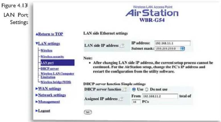
Set LAN side Ethernet settings
LAN Side IP address - Allows ad min is tra tor to specify a static IP and Subnet Mask for the LAN side of the AirStation.
Note: If the AirStation's IP address is changed, the confi guring computer's IP must be changed to the same range to continue confi guration. If the LAN IP is changed, restart the AirStation. (Section 4.4.10).
DHCP Server Function Simple Setting - Allows administrator to enable/disable the DHCP server function for the AirStation LAN side. Select Use to enable and Do not use to disable the function. Once Use is selected, the assigned IP address range can be specified. Enter the starting LAN IP address and total number of computers.
■ Note: If there is another DHCP server on the network, one either must be disabled or the IP range must be changed to avoid conflicts derived from overlapping DHCP scopes.

4.1.4 DHCP Server
Allows a more advanced configuration of the DHCP server functions.
DHCP Server Function - Allows administrator to enable/disable the DHCP server function for the AirStation LAN side. Select Use to enable or Do not use to disable this function.
If the DHCP service is enabled, wireless and wired clients may receive IP addresses and other network information from the AirStation. If the DHCP server is turned off, all client PC's must have unique, static IP addresses and valid network settings manually entered. Check with your LAN administrator for static IP information.
Assigned IP address (Range As sign ment)
- Sets the beginning address and range of addresses to be assigned by the AirStation's DHCP server function. Select up to 253 consecutive addresses (nodes). The IPs to be excluded from the range specification should be entered in the specified field.
Lease duration - Specifies the time in hours (1-999) an assigned IP address is valid. If the client computer does not request a renewal of IP address before the lease period expires, the AirStation can issue the IP to another client computer.
Default Gateway - Allows administrator to use the Default Gateway address (the AirStation's IP address), assign a specific Gateway address, or block clients from Gateway notification.
DNS server - Allows administrator to use the default DNS address (the AirStation's IP address), assign specific DNS addresses, or block clients from DNS address notification.
WINS server - Allows administrator to use a WINS address. Select auto assignment of the IP address, enter a specific WINS IP address, or block clients from the WINS address notification.
Domain name - Allows administrator to use an assigned domain name, assign a specific domain name, or block clients from domain name notification. Domain names will be sent to LAN computers when an IP address is assigned. Enter a maximum of 64 alphanumeric characters.
Figure 4.1.4b
Manual IP and MAC Address Assignment Settings
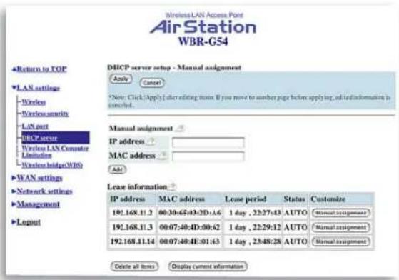
Manual IP and MAC Address As sign ment - Allows administrator to add additional leased IP addresses tied to a specific MAC address. When a specific MAC address connects to the AP, the IP address specified will be given to that client. Display/Delete lease information - List of IP addresses, MAC addresses, lease periods and status is displayed.
Figure 4.1.5b Wireless LAN Computer Limitation
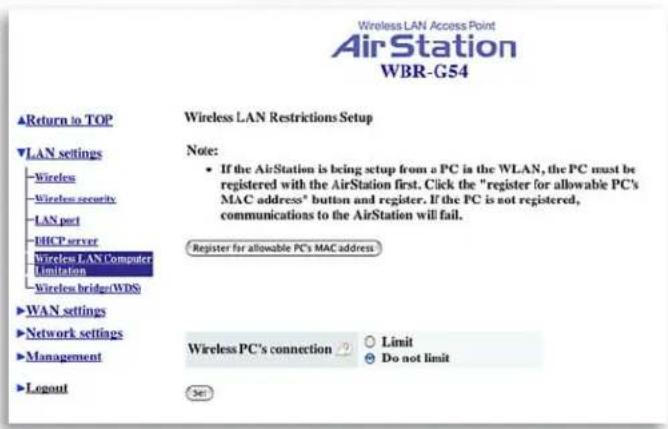
4.1.5 Wireless LAN Computer Limitation
Wireless PC's Connection - Select Limit to restrict wireless connections to the registered adapters in the list. Select Do not limit to disable MAC address fi ltering.
Figure 4.1.5b
Register for
Allowable PC's
MAC Address

Register for allowable PC's MAC address - MAC access restriction set up in LAN. Input the MAC addresses that are allowed to communicate with the AirStation.
MAC address list - Displays a table list of all MAC addresses allowed to communicate with the AirStation.
Figure 4.1.6 Wireless Bridge (WDS) Settings
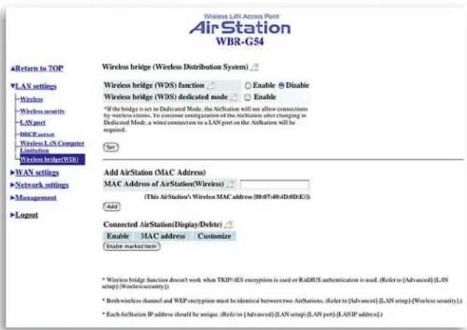
4.1.6 Wireless Bridge (WDS)
The Wireless Distribution System supports peer-to-peer AP communication.
Wireless Bridge (WDS) Function - Select Enable to allow Bridge (WDS) mode between AirStations or Disable to block communication between AirStations.
Wireless Bridge (WDS) dedicated mode
- Select Enable to restrict wireless computer communication with the AirStation.
■ Note: Both AirStations must support WDS and be on the same channel.
Add AirStation (wireless MAC Address): Allows administrator to input the wireless MAC address of AirStations for Bridge (WDS) communication. The wireless MAC address is found in the Management section => System Information, labeled wireless MAC address. (Section 4.4.1)
Figure 4.1.6b Wireless Bridge (WDS) Settings

To enable WDS, set the Wireless Bridge (WDS) function to Enable.
Enter the Wireless MAC address of the AirStation to communicate with in the form of two characters separated by a colon and click Add.
MAC Address Ex: 00:00:00:00:00:00
Up to six AirStation MAC addresses may be registered.
Click Apply under Wireless Bridge (WDS) setting when the wireless Mac addresses AirStation are entered.
Repeat this process on every other AirStations used in Bridge (WDS) mode.
Figure 4.2.1 WAN port Setup

4.2 WAN Settings
4.2.1 WAN Port
Communication Method of Wired WAN
- Select port speed and type of duplex connecting to the WAN port. If unknown, select Auto negotiation.
MAC Address of WAN - Set the AirStation MAC address to be used for WAN com mu-ni ca tion.
IP Address of WAN - Allows administrator to select DHCP server, PPPoE, or manual setting for the WAN port of the AirStation.
Auto IP assignment from DHCP server - acquire the IP address automatically from the DHCP server.
Use PPPoE client - If selected, the information listed below must be entered.
Manual setting - Enter the appropriate IP address and subnet mask.
PPPoE Setting (for enabling PPPoE Client function) - Allows administrator to use PPPoE as specified by the ISP.
Figure 4.2.1a
PPPoE
Settings
Screen
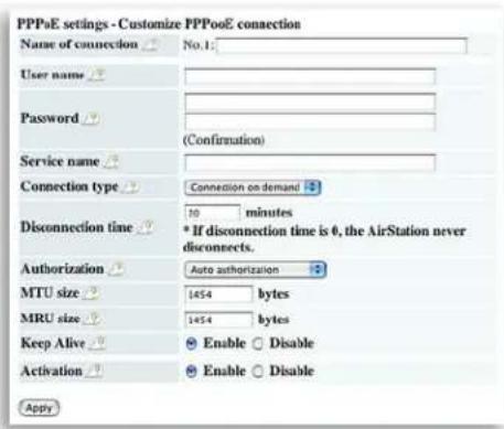
The following parameters should be entered for PPPoE Settings:
Name of Connection - Enter the name of your connection.
User Name - Enter the user name (up to 64 alphanumeric characters) for PPPoE au tho ri za tion.
Password - Enter password provided by ISP (up to 64 alphanumeric characters). Re-enter password in the Confirmation box.
Service Name - Enter the PPPoE service name (up to 64 alphanumeric characters). If ISP doesn't require service name, leave blank.
Connection Type - Select from:
- Continuous Connection - connects im me di ate ly after setting and never disconnects.
- Connect on Demand - Reconnects when the disconnect time elapses.
- Manual - Disables Automatic Connection. Connects to Internet using the connect button on the initial settings page.
The Connect button will not appear until PPPoE is set.
Disconnection Time - Specify the number of minutes (0-1440) before automatic disconnect is performed. If "0" is entered, disconnect function is disabled. If Continuous Connection is selected, the timer is disabled.
Authorization - Authorization method for accessing the ISP PPPoE server. If unknown, select Auto authorization.
MTU (Maximum Transmit Unit) Size - Maximum Transmit Unit (578-1492) when using PPPoE.
MRU (Maximum Receive Unit) Size - Maximum Receive Unit (578-1492) when using PPPoE.
Keep Alive - Enables the PPPoE client to send a Link Control Protocol (LCP) echo request to the PPPoE server once per minute. If there is no reply within six minutes, the client disconnects. Set to Disable if frequent disconnection occurs.
Activation - Enable/disable registered connection settings. If disabled, the connection is not permitted.
Figure 4.2.2 Network of WAN
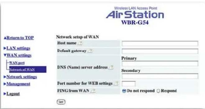
4.2.2 Network WAN
WAN side (Internet) parameters.
Host Name - Enter the host name as desired.
Default Gateway - A default gateway IP should be assigned to the AirStation. If unknown, leave blank. If Auto IP assignment from DHCP Server is selected in section 4.2.1, a gateway IP is assigned automatically, provided the DHCP server is set to provide one.
DNS Server Address - Enter the primary and secondary DNS address(es) of the server to be used by the AirStation for DNS resolution.
If DNS was set to Do not use (Section 4.1.4), leave blank. If Auto IP assignment from DHCP Server was selected, DNS addresses are assigned automatically, provided the DHCP server is set to provide them.
Port Number for WEB Settings - Set a specific port number when remote setup of the AirStation is planned.
PING from WAN - Allows a PING test from WAN side. Select Do not respond or Respond.
Fig ure 4.3.1
Routing Setup

4.3 Network Setting 4.3.1 Routing Setup
RIP transmission to WAN - Allows RIP transmission or None (no RIP) to WAN
RIP reception from WAN - Allows RIP reception or None (no RIP) from WAN
RIP transmission to LAN - Allows RIP transmission or None (no RIP) to LAN
RIP reception from LAN - Allows RIP reception or None (no RIP) from LAN
Fig ure 4.3.1b Add routing table entry
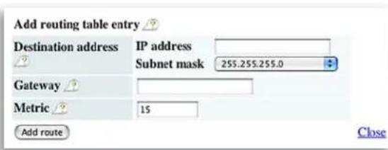
Click Add Route to Add Routing Table Entry
- Destination address - Network IP address and subnet mask.
- Gateway - Address through which the packet passes before it reaches the des ti na tion address.
- Metric - Number of routers (1-15) to be passed before the packet reaches its destination.
Display current information - Allows administrator to view and delete routing information.
Figure 4.32
Address:
Translation
Setup
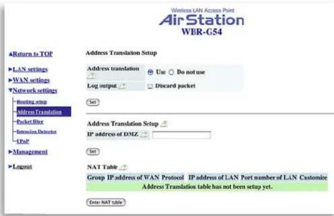
4.3.2 Address Translation
Address Translation - Select Use or Do not Use. Address Translation must be enabled for client computers to connect to the Internet. Selecting Use enables the following functions:
- IP Masquerade - When the LAN computer connects to the WAN side, the IP address of LAN computer is dynamically translated to become the WAN IP address of the AirStation. Multiple LAN computers can share one WAN IP address to access the Internet.
- Static IP address translation -When the WAN requests connection to the LAN, the WAN IP address of the AirStation is translated into the IP address of the LAN computer.
Log Output - Allows NAT log to be gen er at ed and issued. Select Discard Packet to disable.
IP address of DMZ - Allows administrator to set the DMZ address. Incoming packets containing no recognizable destination port information will be re di rect ed to the DMZ's IP address.
Display/Delete NAT Table - Allows ad min is tra tor to delete NAT tables.
Fig ure 4.3.2b
Address
Translation
Setup
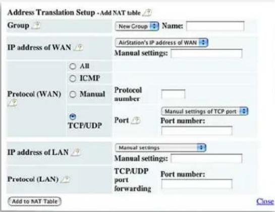
Add NAT Table
Group - Specify a group (up to 16 characters) that the NAT rule belongs.
Click New Group to create new group or select an existing group to add a NAT rule to it.
IP address of WAN - Select AirStation's IP address of WAN or Manual setting. For Manual setting, enter the IP address used by the WAN computer to connect to the local computer. Some network applications (online games or streaming software) require adding Address Translation tables).
Protocol (WAN):
• All - Selects all IP protocols.
• ICMP - Network Diagnostic Protocol (I).
- Manual - Specify the protocol number (0-255).
- TCP/UDP - Enter port number.
IP address of LAN - Select Manual and enter the destination IP address of the LAN computer; or select AirStation's IP address of LAN.
- Click Add to NAT table.
Protocol (LAN) - Enter destination port number. If left blank, the packets are transferred to the same port number as the source port number.
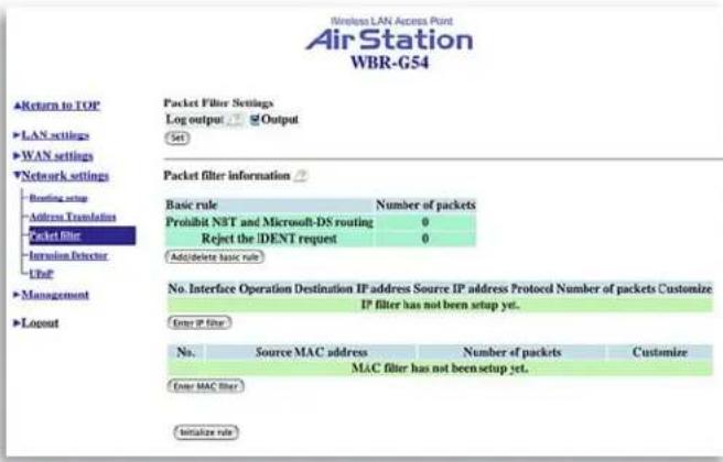
Figure 4.3.3 Packet Filter Setup
4.3.3 Packet Filter
Log Output - Select Output to activate the packet fi iter log.
Packet Filter Information
Basic Rule - Click add/delete basic rules.
Place a check mark next to the basic rule to enable
• Prohibit setup from wireless LAN.
Prohibits administration from a wireless computer.
• Prohibit setup from wired LAN.
Prohibits administration from a wired computer.
- Prohibit setup via wireless bridge access point. A setup from the personal computer connected to another AirStation in a wireless bridge is not allowed.
• Prohibit NBT and Microsoft-DS routing.
Prevent unexpected external access via Microsoft network sharing.
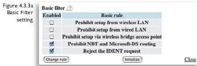
- Reject the IDENT request.
The AirStation sends reject packets if it receives an IDENT request. Use this filter when the communication speed goes down using a network application like E-mail, ftp and WEB.
* If IDENT requests are forwarded to a LAN side client by address translation setting (DMZ or TCP port :113), this basic rule is ignored.
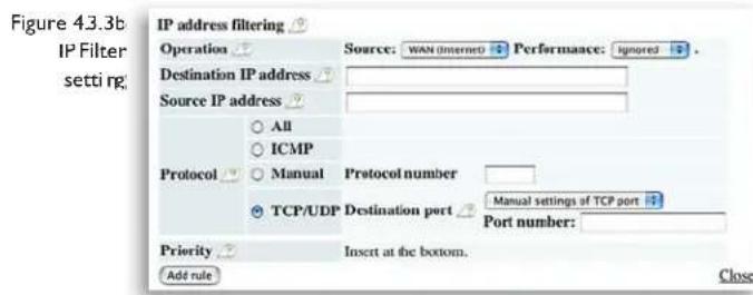
IP Filter setting - Limits the type of packets allowed to pass between the WAN and LAN. The maximum number of rules is 32.
- Operation - Packets from WAN (or LAN), select ignored, rejected, or accepted. Select the operation to be performed on the packets.
Packets from:
- WAN side - packets coming from the WAN side will be fi itered.
• LAN side - packets from the LAN side will be fi Itered. Are :
- Ignored - Stop the packet and do not route it.
- Rejected - Return the rejected packet to the point of origin.
• Accepted - Pass the packet through.
- Destination IP Address - The IP address to be filtered.
- Source IP Address - The IP address designated for filtering. If all IP addresses must be filtered, leave this box blank.
Warning: If administrator selects Packet from LAN is Deny or Reject, the administrator will no longer have access to the AirStation configuration screens. This function prohibits setup from a wireless computer. The AirStation can be returned to the factory default settings by holding down the INIT button on the back of the unit for five seconds.
Protocol - Mark and select a specific protocol. Select from all protocols, ICMP, arbitrary protocol number and TCP/UDP protocol number.
• All - Selects all IP protocols.
• ICMP - Network Diagnostic Protocol (I).
• Manual - Enter protocol number (0-255).
- TCP/UDP Destination Port - Select TCP or UDP, then enter port number.
Priority - Specify the priority an item. The smaller the number, the higher the priority.

MAC Filter - Click Enter MAC filter to enter MAC address.
Source MAC address -The MAC address of the source of the packets that will be filtered may be set. Click Add rule when complete.
■ Note: If configuring from a wireless computer, add your MAC address to the list of authorized wireless LAN PCs. The MAC address must be in two-digit groups separated by colons. Example: 00:40:26:00:11:22
Click Apply when settings are complete.
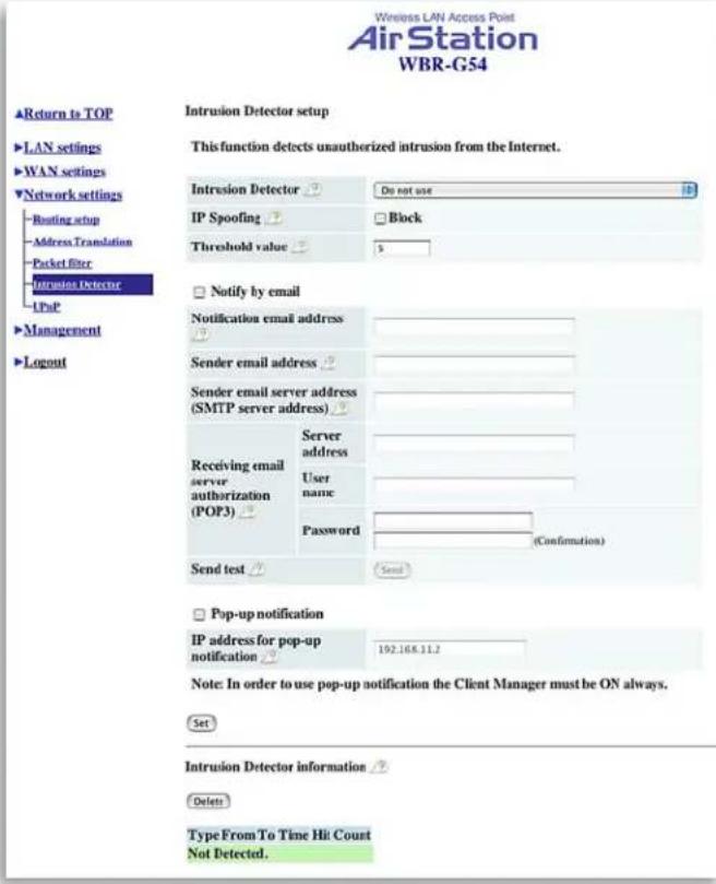
Figure 4.3.4 Intrusion Detector Setup
activity detected by the Intrusion Detector service.
4.3.4 Intrusion Detector
The Intrusion Detector watch guards and prevents unauthorized access from the WAN (Internet) This function also records information on unauthorized access attempts
Intrusion Detector - Select Do not use, Use or Use (Apply Packet filter setting for Intrusion Detector setting).
IP Spoofing - Check Block to prevent IP spoofing.
Threshold Value - Enter the number (1-999) of packets before notification occurs.
Notify by email
- Notification email address - Enter destination email address
- Sender email server address - Enter SMTP server address
- Receiving email server authorization - Enter POP3 Server address, User name and Password
- Send test - Click Send to test notification
Pop-up notification - Pop-up window alert of unwanted activity. Client Manager must be on to use this feature (not recommended).
- Destination IP address - Enter address to be notified
Intrusion Detector information - displays log
Figure 4.3.5 UPnP Setting

4.3.5 UPnP
Select Use to enable UPnP (Universal Plug and Play). When a computer with UPnP support connects to the AirStation, that computer automatically receives configuration information from the AirStation.
Figure 4.4.1 System Information

4.4 Management (Network Diagnosis Settings)
4.4.1 System information
System information of the AirStation is obtained here.
- Model name - Displays model and firmware version
• AirStation Name - Displays AirStation host name
• DHCP Server function - Displays On or Off - Wireless - Displays the wireless LAN settings such as wireless MAC address and wireless firmware.
• LAN - Displays the AirStation LAN settings - WAN - Displays the AirStation WAN settings
- Default Gateway - Displays default gateway settings
- WAN side IP address auto acquisition
- This is the method to acquire the IP address from the WAN (Internet) side DHCP server.
Figure 4.4.2 Name and Password Setup

4.4.2 Name and Password
AirStation name - When using multiple AirSta- tions, select a unique name to make it easier to identify each AirStation.
Administrator name - "root", cannot be changed
Administrator password - Allows the administrator to enter an administrator password to restrict access to the setting screens.
- New Password - Enter new password. Enter up to eight alphanumeric characters (case sensitive)
- Confirm Password - Reenter the new password for confirmation
Figure 4.4.3 Time Setup Screen
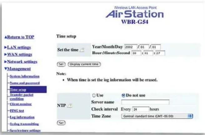
4.4.3 Time setup
Time setup - Enter the current date and time, and click Set.
NTP - Network Time Protocol. Select Use or Do not use.
Note: If NTP is used, time is set au to mat i cal ly.
NTP server name - Enter the NTP server name
Check Interval - Enter the time interval for time check frequency
Time Zone - Select local time zone
Click Set.
Figure 4.4.4 Transfer Packet Condition Screen
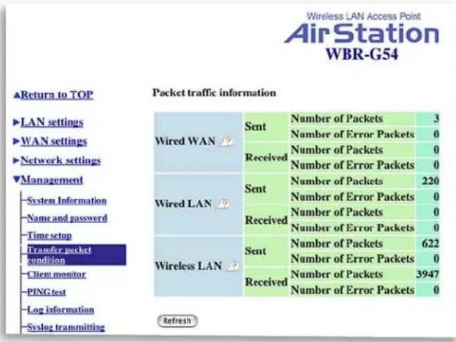
4.4.4 Transfer Packet Condition
Displays number of packets sent and received for:
Wired WAN
Wired LAN
Wireless LAN
Click Refresh to start new transfer packet log.
Figure 4.4.5
Client
Monitor
Screen
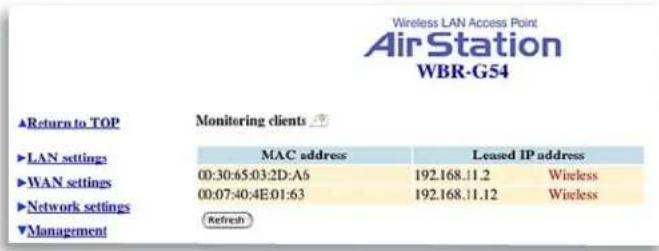
4.4.5 Client Monitor
Displays the LAN side clients (computers) that are accessing the AirStation.
- MAC address - Shows client's MAC address.
- Leased IP address - Shows the IP address that is assigned to the client from the DHCP server.
The network medium is indicated as wireless or wired depending on the client.
■ Note: Wired computers that have static IP addresses will not appear in the Client Monitor list.
Figure 4.4.6
PING Test
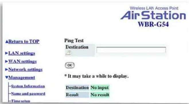
4.4.6 PING Test
Performs a PING test from the AirStation to a LAN or WAN address.
Enter the target IP address and click OK (e.g. 192.168.11.2 - OR- www.buffalotech.com)
Figure 4.4.7
Log
Information
Screen

4.4.7 Log Information
Display log info level - Select Error and/or Notify to specify the types of reports to be logged by the AirStation.
Display log info - Select the specific reports to be logged.
Log information - Displays recorded logs.

4.4.8 Syslog transmitting
Select Use or Do not use to enable or disable the AirStation's ability to transmit information to a Syslog server.
- Syslog Server - Enter the IP address of the Syslog server.
- Log Information Level - Select Error and/or Notice to specify the types of reports to be sent to the Syslog server.
- Log Information - Select the specific reports to be sent to the Syslog server.
■ Note: A server running a Syslog service is required for this.

4.4.9 Save/Restore Settings
Save current settings - Click Save to open the fi le saving dialog and save current AirStation settings to a fi le.
Restored saved settings - Restores settings from a file that has been saved. Click Choose file to select the saved file and click Restore.
Note: If the setting fi le is saved by a newer fi rmware than the current one, the AirStation can't restore the settings.

4.4.10 Initialization/Reboot
Click Restart to reboot AirStation
Click Restore to reset the AirStation to default factory settings.
■ Note: Resetting to default factory settings will erase all settings and passwords previously entered.
![Figure 4.4.11 Firmware Update Wireless LAN Access Point AirStation WBR-G54 ▲Return to TOP Firmware Update Firmware file name → Choose File no file selected ►LAN settings The current firmware version is [1.30]. ►WAN settings Firmware Update ►Network settings ▼Management](/content/2026/05/781795/images/b169e77e6bbbbea7c5d96d6ae5bf9cf85f8bce2bb4eb29f731f82cbf2755b6e9.jpg)
4.4.11 Firmware Update
Firmware file name - Click Choose file to browse the path and filename for new firmware. Click Firmware Update to load firmware to the AirStation.
■ Note: Firmware update does not erase current user settings.
■ Note: Firmware Updates can only be performed by the recommended Web Browsers below on the Macintosh.
OSX - The AirStation can be updated using Netscape v7 or Apple's Safari Web browser v1.0 or later.
OS9 - The AirStation can be updated using Netscape v4.5 or later or Internet Explorer 4.5 or later.
4.4.12 Logout - This feature logs administrator out of the AirStation web interface. Only one user at a time can configure the AirStation with the web interface.
5
Specifications
Physical Specifications
Dimensions W3 x H6.75 x D6.1in. (76 x 171 x 155mm)
Weight 1 lb. (445g)
Temperature & Humidity
Operation 0° to 40°C
Maximum humidity 80%
Transit/Storage 0° to 40° C maximum humidity 80% (no condensation)
Power Characteristics
Transmit Mode I.1A (Nominal),
Power Supply 3.3 V
Regulatory Information
Wireless communication is often subject to local radio regulations. Although AirStation wireless networking products have been designed for operation in the license-free 2.4 GHz band, local radio regulations may impose limitations on the use of wireless com mu ni ca tion equipment.
Networking Characteristics
Compatibility
- IEEE 802.11g and IEEE802.11b Standards for Wireless LANs
• Wi-Fi (Wireless Fidelity) certified by the Wi-Fi Alliance.
Host Operating System
Microsoft Windows® 98SE/ME/NT4.0/2000/XP, Unix, Linux and MacOS
Media Access Protocol
Wired - CSMA/CD (Collision Detection)
Wireless - CSMA/CA (Collision Avoidance) with Acknowledgment (ACK)
Radio Characteristics
RF Frequency Band 2.4 GHz (2400-2483 MHz)
II selectable channels (3 non-overlapping) (USA)
Modulation Technique Direct Sequence Spread Spectrum
Spreading 11-chip Barker Sequence
Bit Error Rate (BER) Better than 10 -5
Nominal Output Power 15 dBm
Communication Range
*Speed
Indoor
Outdoor
| 54Mbps | 65ft(20m) | 165ft(50m) |
| 18Mbps | 195ft(60m) | 490ft(150m) |
| 11Mbps | 245ft(75m) | 590ft(180m) |
| 1Mbps | 410ft(125m) | 1870ft(570m) |
*All Distances are estimated. Wireless connections may be affected as physical conditions and circumstances vary.
Table "Communication Range" lists the typical range when in ordinary use.
Receiver Sensitivity -92 dBm
Delay Spread (at FER of <1%) 65 ns 225 ns 400 ns 500 ns
- The range of wireless devices can be affected by metal surfaces, solid high-density materials and obstacles in the signal path.
Note: The range values listed in Table “Radio Characteristics” are typical distances as measured at Buffalo Technology AirStation laboratories. These values are provided for your guidance but may vary according to the actual radio conditions at the location where the AirStation product is installed.
AirStation IEEE 802.1 Channel Sets
The range of the wireless signal is related to the Transmit Rate of the wireless communication. Communications at a lower Transmit range may travel longer distances.
Center Channel ID FCC
| 2412
2 2417
3 2422
4 2427
5 2432
6 2437
7 2442
8 2447
9 2452
10 2457
II 2462*
* default channel
6
Troubleshooting
Common Problems:
- Out of range, client cannot connect to the AirStation.
- Configuration mismatch, client cannot connect to the AirStation.
• Absence or conflict with the Client Driver. - Conflict of another device with the AirStation hardware.
B.I.I LED Activity
Monitoring LED activity helps identify problems.
• Power LED should be GREEN,
- Wireless LED should be GREEN if the line is active. If is it blinking GREEN, wireless communication is active.
- Ethernet LED should be GREEN (100Mbps) or AMBER (10Mbps) while the communication is active.
• DIAG LED should be during normal operation.
DIAG LED Activity
Unplug the power for three seconds. Plug the power back in to monitor the DIAG LEDs during start-up. If any symptoms match section B.1.1, call the Buffalo Tech Support line 24 hours a day, 7 days a week at
866-752-6210 or email info@buffalotech.com.
Table B.1.1 DIAG LED Activity Table
| DIAG LED Display Time Description/Action | ||
| Continuous Red | Starting | RAM Error Red flash, 2 times Starting Flash ROM Error |
| Red flash, 3 times Starting A problem in the wired LAN side | ||
| Red flash, 4 times Starting A problem in the wireless LAN side | ||
| Red flash, 5 times Starting A problem with the AirStation | ||
B. I.2 LEDs Work But Client PC Cannot Connect to Network
If the LEDs indicate that the network is working properly (Power LED is on, Transmit/Receive LED blinks), check the TCP/IP settings of the network.
Changing Client TCP/IP Settings in Windows
Consult the LAN Administrator for TCP/IP settings.
Windows
To add or change the TCP/IP Settings:
- On the Windows task bar click Start.
- Select Settings, then Control Panel.
- Double-click on the Network icon to view the Network Properties.
- From the list of installed components, verify the TCP/IP => Buffalo wireless LAN adapter protocol (or appropriate wireless LAN adapter) is installed.
- If this protocol is not yet installed, click the Add button and select the TCP/IP protocol from the list. Refer to Windows Help for more information.
- If this protocol is installed, select this protocol and click the Properties button. Verify the parameters match the settings provided by your LAN Administrator. Make changes if necessary, and click OK.
- When prompted, restart your computer.
Macintosh OS X
- Open the System Preferences from your Dock
-
Click Network
-
Select Airport under Show
- Select DHCP or input static IP Address
Macintosh OS9
- Open the Control Panels
- Double-click TCP/IP
- Select Airport
- Select DHCP or input static IP Address
B. I.3 Other Problems
Please refer to www.buffalotech.com for further reference materials or call Buffalo's Toll-Free Tech Support 24 hours a day, 7 days a week at 866-752-6210.
B. I.3 Other Problems
Please refer to www.buffalotech.com for further reference materials.
7
Glossary
10BaseT or 100BaseTx: 802.3 based Ethernet network that uses UTP (Unshielded twisted pair) cable and a start topology. 10 is 10 Mbps and 100 is 100 Mbps.
802.1x: The standard for wireless LAN authentication used between an AP and a client. 802.1x with EAP will initiate key handling.
Ad-Hoc Network: The wireless network based on a peer-to-peer communications session. Also referred to as AdHoc.
Bandwidth: The transmission capacity of a computer or a communication channel, stated in Megabits per second (Mbps).
BSS (Basic Service Set): An 802.11 networking framework that includes an Access Point.
Client: A PC or workstation on a network.
Cross-Over Wiring: A UTP cable that has its transmit and receive pair crossed to allow communications between two devices.
DCE (Data Communications Equipment): Hardware used for communication with a Data Terminal Equipment (DTE) device.
Default Gateway: The IP Address of either the nearest router or server for the LAN.
DHCP (Dynamic Host Configuration Protocol): Based on BOOTP, it uses a pool of IP addresses, which it assigns to each device connected to it, and retrieves the address when the device becomes dormant for a period of time.
DNS (Domain Name System): System used to map readable machine names into IP addresses
Driver: Software that interfaces a computer with a specific hardware device.
DSSS (Direct Sequence Spread Spectrum): Method of spreading a wireless signal into wide frequency bandwidth.
DTE (Data Terminal Equipment): Device that controls data flowing to and from a computer.
Dynamic IP Address: An IP address that is automatically assigned to a client station in a TCP/IP network, typically by a DHCP server.
ESS (Extended Service Set): A set of two or more BSSs that form a single sub-network. ESS-ID is user identification used in the ESS LAN configuration.
Ethernet: The most widely used architecture for Local Area Networks (LANs). It is a shared-media network architecture. The IEEE 802.3 standard details its functionality.
Ethernet cable: A wire similar to telephone cable that carries signals between Ethernet devices.
Firmware: Programming inserted into programmable read-only memory, thus becoming a permanent part of a computing device.
Frame: A fixed block of data, transmitted as a single entity. Also referred to as packet.
Full-Duplex: To transmit on the same channel in both directions simultaneously.
Gbps (Giga Bits per second): One billion bits per second.
Half-duplex: To transmit on the same channel in both directions, one direction at a time.
Hub: A device which allows connection of computers and other devices to form a LAN.
IEEE (Institute of Electrical and Electronics Engineers): The professional organization which promotes development of electronics technology.
IP (Internet Protocol) Address: A unique 32-binary-digit number that identifies each sender or receiver of information sent in packets.
Infrastructure: A wireless network or other small network in which the wireless network devices are made a part of the network through the Access Point.
ISP (Internet Service Provider): A company that provides access to the Internet and other related services.
IV (Initialization Vector): The header section of a message packet.
LAN (Local Area Network): A group of computers and peripheral devices connected to share resources.
LED (Light Emitting Diode): The lights on a hardware device representing the activity through the ports.
MAC (Medium Access Control) Address: A unique number that distinguishes network cards.
Mbps (Mega Bits Per Second): A measurement of millions of bits per second.
MDI/X (Media Dependent Interface/Cross-over): Port on a network hub or switch that crosses the incoming transmit lines with the outgoing receive lines.
MHz (MegaHertz): One million cycles per second.
MIB II: A database containing performance information and statistics on each device in a network.
NAT (Network Address Translation): An internet standard that enables a LAN to use one set of IP addresses for internal traffic and a second set for external traffic.
NIC (Network Interface Card): An expansion card connected to a computer so the computer can be connected to a network.
Packet: A block of data that is transferred as a single unit, also called a frame or a block.
Packet Filtering: Discarding unwanted network traffic based on its originating address or its type.
PCI (Peripheral Component Interconnect): A bus that is connected directly to the CPU.
PCMCIA (Personal Computer Memory Card International Association) Card: Removable module that adds features to a portable computer.
Ping (Packet Internet Groper): An Internet utility used to determine whether a particular IP address is online.
Plug and Play: Hardware that, once installed (“plugged in”), can immediately be used (“played”), as opposed to hardware that requires manual configuration.
PoE (Power over Ethernet): A mechanism to send DC power to a device using a CAT5 Ethernet cable.
PPPoE (Point-to-Point Protocol over Ethernet): A specification for connecting users on an Ethernet line to the Internet through a common broadband medium.
RADIUS (Remote Authentication Dial In User Service): A server that issues authentication key to clients.
Repeater Hub: A device that collects, strengthens and transmits information to all connected devices, allowing the network to be extended to accommodate additional workstations.
RC4: The encryption algorithm that is used in WEP.
RJ-45 connector: An 8-pin connector used between a twisted pair cable and a data transmission device.
Router: Device that can connect individual LANs and remote sites to a server.
Roaming: The ability to use a wireless device while moving from one access point to another without losing the connection.
Script: A macro or batch file containing instructions and used by a computer to perform a task.
Server: Any computer that makes files or peripheral devices available to users of the network and has a resident Network OS.
SMTP (Simple Mail Transfer Protocol): The protocol used to define and deliver electronic mail (E-mail) from one location to another.
SNMP (Simple Network Management Protocol: An application layer protocol that outlines the formal structure for communication among network devices.
Static IP Address: A permanent IP address is assigned to a node in a TCP/IP network. Also known as global IP.
STP (Shielded Twisted Pair): Twisted Pair cable wrapped in a metal sheath to provide extra protection from external interfering signals.
Subnet Mask: An eight-byte address divided into 4 parts separated by periods.
TCP/IP (Transmission Control Protocol/Internet Protocol: Protocol used by computers when communicating across the Internet or Intranet.
TFTP (Trivial File Transfer Protocol): Simple form of FTP (File Transfer Protocol), which Uses UDP (User Datagram Protocol), rather than TCP/IP for data transport and provides no security features.
TKIP (Temporal Key Integrity Protocol): An encryption method replacing WEP. TKIP uses random IV and frequent key exchanges.
Topology: The shape of a LAN (Local Area Network) or other communications system.
Twisted Pair: Cable that comprises 2 or more pair of insulated wires twisted together.
UDP (User Datagram Protocol): A communication method (protocol) that offers a limited amount of service when messages are exchanged between computers in a network. UDP is used as an alternative to TCP/IP.
Uplink: Link to the next level up in a communication hierarchy.
UTP (Unshielded Twisted Pair) cable: Two or more unshielded wires twisted together to form a cable.
WAN (Wide Area Network): A networking system covering a wide geographical area.
WEP (Wired Equivalent Privacy): An encryption method based on 64 or 128-bit algorithm.
Web Browser: A software program that allows viewing of web pages.
Wi-Fi (Wireless Fidelity): An organization that tests and assures interoperability among WLAN devices.
Wire Speed: The maximum speed at which a given packet can be transferred using Ethernet and Fast Ethernet standard specifications.
WLAN (Wireless LAN): A LAN topology using wireless devices.
VPN (Virtual Private Network): A security method to connect remote LAN users to a corporate LAN system.
8
FCC / CE Information
Federal Communication Commission Interference Statement
This equipment has been tested and found to comply with the limits for a Class B digital device, pursuant to Part 15 of the FCC Rules. These limits are designed to provide reasonable protection against harmful interference in a residential installation. This equipment generates, uses and can radiate radio frequency energy and, if not installed and used in accordance with the instructions, may cause harmful interference to radio communications. However, there is no guarantee that interference will not occur in a particular installation. If this equipment does cause harmful interference to radio or television reception, which can be determined by turning the equipment off and on, the user is encouraged to try to correct the interference by one of the following measures:
• Re-orient or relocate the receiving antenna.
- Increase the separation between the equipment and receiver.
- Connect the equipment into an outlet on a circuit different from that to which the receiver is connected.
- Consult the dealer or an experienced radio/TV technician for help.
FCC Caution: To assure continued compliance, (example - use only shielded interface cables when connecting to computer or peripheral devices). Any changes or modifications not expressly approved by the party responsible for compliance could void the user's authority to operate this equipment.
This device complies with Part 15 of the FCC Rules. Operation is subject to the following two conditions: (1) This device may not cause harmful interference, and (2) this device must accept any interference received, including interference that may cause undesired operation.
IMPORTANT NOTE: FCC RF Radiation Exposure Statement:
This equipment complies with FCC RF radiation exposure limits set forth for an uncontrolled environment. This equipment should be installed and operated with a minimum distance of 20 centimeters between the radiator and your body.
This transmitter must not be co-located or operating in conjunction with any other antenna or transmitter. R&TTE Compliance Statement
This equipment complies with all the requirements of the DIRECTIVE 1999/5/EC OF THE EUROPEAN PARLIAMENT AND THE COUNCIL of 9 March 1999 on radio equipment and telecommunication terminal Equipment and the mutual recognition of their conformity (R&TTE). The R&TTE Directive repeals and replaces in the directive 98/13/EEC (Telecommunications Terminal Equipment and Satellite Earth Station Equipment) As of April 8, 2000.
Safety
This equipment is designed with the utmost care for the safety of those who install and use it. However, special attention must be paid to the dangers of electric shock and static electricity when working with electrical equipment. All guidelines of this manual and of the computer manufacturer must therefore be allowed at all times to ensure the safe use of the equipment.
EU Countries intended for use
The ETSI version of this device is intended for home and office use in Austria, Belgium, Denmark, Finland, France (with Frequency channel restrictions), Germany, Greece, Iceland, Ireland, Italy, Luxembourg, Norway, The Netherlands, Portugal, Spain, Sweden, Switzerland and United Kingdom.
The ETSI version of this device is also authorized for use in EFTA member states Iceland, Liechtenstein, Norway and Switzerland.
EU Countries Not intended for use None.
Potential restrictive use
France: Only channels 10, 11, 12, and 13.
9
Warranty Information
Buffalo Technology (Melco Inc.) products comes with a two-year limited warranty from the date of purchase. Buffalo Technology (Melco Inc.) warrants to the original purchaser the product; good operating condition for the warranty period. This warranty does not include non-Buffalo Technology (Melco Inc.) installed components. If the Buffalo product malfunctions during the warranty period, Buffalo Technology/(Melco Inc.) will, replace the unit, provided the unit has not been subjected to misuse, abuse, or non-Buffalo Technology/(Melco Inc.) authorized alteration, modifi cations or repair.
All expressed and implied warranties for the Buffalo Technology (Melco Inc) product line including, but not limited to, the warranties of merchantability and fitness of a particular purpose are limited in duration to the above period.
Under no circumstances shall Buffalo Technology/(Melco Inc.) be liable in any way to the user for damages, including any lost profits, lost savings or other incidental or consequential damages arising out of the use of, or inability to use the Buffalo products.
In no event shall Buffalo Technology/(Melco Inc.) liability exceed the price paid for the product from direct, indirect, special, incidental, or consequential damages resulting from the use of the product, its accompanying software, or its documentation. Buffalo Technology/(Melco Inc.) does not offer refunds for any product.
@ 2003 Buffalo Technology (Melco, Inc.)
10
Contact Information
ADDRESS
Buffalo Technology (USA), Inc.
4030 West Braker Lane, Suite 120
Austin, TX 78759-5319
GENERAL INQUIRIES
Monday through Friday
8:30am-5:30pm CST
Direct: 512-794-8533
Toll-free: 800-456-9799
Fax: 512-794-8520
Email: sales@buffalotech.com
TECHNICAL SUPPORT
North American Technical Support by phone is available 24 hours a day, 7 days a week. (USA and Canada).
Toll-free: (866) 752-6210
Email: info@buffalotech.com
- WIRELESS BROADBAND ROUTER BASE STATION-G
- WBR-G54
- TABLE OF CONTENTS
- INTRODUCTION....4
- INSTALLATION/SETUP 7
- STANDARD SETTINGS 8
- ADVANCED SETTINGS ...... II
- 1
- INTRODUCTION
- I.I AIRSTATION 54MBPS WIRELESS BROADBAND ROUTER BASE STATION
- (WBR-G54)
- 1.2 AIRSTATION WIRELESS NETWORK FEATURES
- 1.3 HOME NETWORKING
- I.4 SOHO/SMB NETWORKING
- 1.5 SYSTEM REQUIREMENTS
- 1.6 AIRSTATION WBR-G54 PACKAGE CONTENTS
- 1.7 PRODUCT VIEWS
- 1.8 ABOUT THE AIRSTATION CD
- 2
- INSTALLATION/SETUP
- 3
- STANDARD SETTINGS
- 3.1 INTRODUCTION
- 3.2 SETUP PREPARATION
- 3.3 SETUP OVERVIEW
- 3.4 OPEN THE SETUP SCREEN
- 3.5 ENTER ISP INFORMATION
- 3.5.1 DSL BUTTON
- AUTOMATIC IP ASSIGNMENT BY ISP
- ENTER IP ADDRESS MANUALLY
- PPPOE CONNECTION
- 3.5.2 CATV BUTTON
- 3.5.3 LINE TEST TAB
- 3.5.4 SECURITY TAB
- ADVANCED SETTINGS
- 4.1 LAN SETTING
- 4.1.1 WIRELESS
- 4.1.2 WIRELESS SECURITY
- RADIUS AUTHENTICATION
- 4.1.3 LAN PORT
- 4.1.4 DHCP SERVER
- ASSIGNED IP ADDRESS (RANGE AS SIGN MENT)
- 4.1.5 WIRELESS LAN COMPUTER LIMITATION
- 4.1.6 WIRELESS BRIDGE (WDS)
- WIRELESS BRIDGE (WDS) DEDICATED MODE
- 4.2 WAN SETTINGS
- 4.2.1 WAN PORT
- COMMUNICATION METHOD OF WIRED WAN
- CONNECTION TYPE - SELECT FROM
- 4.2.2 NETWORK WAN
- 4.3 NETWORK SETTING 4.3.1 ROUTING SETUP
- 4.3.2 ADDRESS TRANSLATION
- ADD NAT TABLE
- 4.3.3 PACKET FILTER
- PACKET FILTER INFORMATION
- 4.3.4 INTRUSION DETECTOR
- 4.3.5 UPNP
- 4.4 MANAGEMENT (NETWORK DIAGNOSIS SETTINGS)
- 4.4.1 SYSTEM INFORMATION
- 4.4.2 NAME AND PASSWORD
- 4.4.3 TIME SETUP
- 4.4.4 TRANSFER PACKET CONDITION
- 4.4.5 CLIENT MONITOR
- 4.4.6 PING TEST
- 4.4.7 LOG INFORMATION
- 4.4.8 SYSLOG TRANSMITTING
- 4.4.9 SAVE/RESTORE SETTINGS
- 4.4.10 INITIALIZATION/REBOOT
- 4.4.11 FIRMWARE UPDATE
- 5
- SPECIFICATIONS
- PHYSICAL SPECIFICATIONS
- TEMPERATURE & HUMIDITY
- POWER CHARACTERISTICS
- REGULATORY INFORMATION
- NETWORKING CHARACTERISTICS
- HOST OPERATING SYSTEM
- RADIO CHARACTERISTICS
- COMMUNICATION RANGE
- 6
- TROUBLESHOOTING
- COMMON PROBLEMS
- B.I.I LED ACTIVITY
- DIAG LED ACTIVITY
- I.2 LEDS WORK BUT CLIENT PC CANNOT CONNECT TO NETWORK
- CHANGING CLIENT TCP/IP SETTINGS IN WINDOWS
- WINDOWS
- MACINTOSH OS X
- MACINTOSH OS9
- I.3 OTHER PROBLEMS
- 7
- GLOSSARY
- 8
- FCC / CE INFORMATION
- FEDERAL COMMUNICATION COMMISSION INTERFERENCE STATEMENT
- IMPORTANT NOTE: FCC RF RADIATION EXPOSURE STATEMENT
- SAFETY
- EU COUNTRIES INTENDED FOR USE
- POTENTIAL RESTRICTIVE USE
- 9
- WARRANTY INFORMATION
- 10
- CONTACT INFORMATION
- ADDRESS
- GENERAL INQUIRIES
- TECHNICAL SUPPORT
Brand : BUFFALO
Model : WBR-G54
Category : Router