
VT650 - Video projector NEC - Free user manual and instructions
Find the device manual for free VT650 NEC in PDF.


| Product Type | Video Projector |
| Model | NEC VT650 |
| Display Technology | 0.9" p-Si TFT active-matrix LCD with Micro Lens Array |
| Native Resolution | 1024 x 768 (XGA) |
| Lamp Type | 160 W NSH (130 W in Eco mode) |
| Lamp Life | Up to 3000 hours in Eco mode |
| Image Size (Diagonal) | 25" to 300" (0.64 - 7.62 m) |
| Throw Distance | 3.5 - 36.6 ft (1.1 - 11.2 m) |
| Lens | Manual zoom and focus, F1.7-2.0, f=33.5-40.2 mm |
| Keystone Correction | ±30° vertical |
| Inputs | RGB (D-Sub 15), Video, S-Video, Audio (3.5mm and RCA), PC Control (Mini DIN 8) |
| Outputs | RGB Monitor Out (D-Sub 15), Audio Out |
| Power Requirement | 100-120 / 200-240 VAC, 50/60 Hz |
| Power Consumption | 225 W (190 W in Eco mode) |
| Dimensions (W x H x D) | 9.57" x 4.0" x 11.2" (243 x 103 x 284 mm) |
| Weight | 8.8 lbs (3.9 kg) |
| Remote Control | Wireless with mouse function |
| Advanced Features | Advanced AccuBlend, Color Management (Gamma, White Balance, Color Correction), Freeze, Magnify |
| Filter Cleaning | Every 100 hours of use |
| Operating Temperature | 32° - 95°F (0° - 35°C) |
Frequently Asked Questions - VT650 NEC
User questions about VT650 NEC
0 question about this device. Answer the ones you know or ask your own.
Ask a new question about this device
Download the instructions for your Video projector in PDF format for free! Find your manual VT650 - NEC and take your electronic device back in hand. On this page are published all the documents necessary for the use of your device. VT650 by NEC.
USER MANUAL VT650 NEC
NEC VT650 users' manual
NEC
Printed in China 7N8P1111
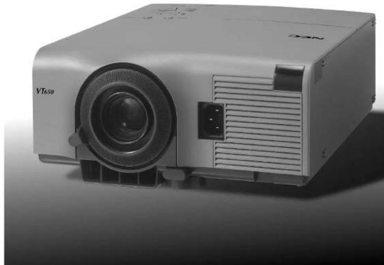
natural_image
Exterior view of a white projector with visible lens and ventilation slots (no text or symbols on body)LIMITED WARRANTY
Except as specified below, the warranty that may be provided by the dealer covers all defects in material or workmanship in this product. The following are not covered by the warranty:
- Any product on which the serial number has been defaced, modified or removed.
- Damage, deterioration or malfunction resulting from:
a. Accident, misuse, abuse, neglect, fire, water, dust, smoke, lightning or other acts of nature, unauthorized product modification, or failure to follow instructions supplied with the product.
b. Repair or attempted repair by non-authorized persons.
c. Any shipment of product (claim must be presented to the carrier).
d. Removal or installation of the product.
e. Any other causes which do not relate to a product defect. - Cartons, carrying cases, batteries, external cabinets, CDROM, or any accessories used in connection with the product.
- Removal or installation charges.
- Cost of initial technical adjustments (set-up), including adjustment of user controls. These costs are the responsibility of the dealer from whom the product was purchased.
- Payment of shipping charges.
GARANTIE LIMITEE
BESCHRÄNKTE GARANTIE
Please read this manual carefully before using your NEC VT650 Projector and keep the manual handy for future reference.
Your serial number is located under the name plate label on the right side of your VT650. Record it here:
CAUTION

To turn off main power, be sure to remove the plug from power outlet.
The power outlet socket should be installed as near to the equipment as possible, and should be easily accessible.
CAUTION

TO PREVENT SHOCK, DO NOT OPEN THE CABINET.
NO USER-SERVICEABLE PARTS INSIDE. REFER SERVICING TO QUALIFIED NEC SERVICE PERSONNEL.

This symbol warns the user that uninsulated voltage within the unit may be sufficient to cause electrical shock. Therefore, it is dangerous to make any kind of contact with any part inside of the unit.

This symbol alerts the user that important information concerning the operation and maintenance of this unit has been provided. The information should be read carefully to avoid problems.
WARNING
TO PREVENT FIRE OR SHOCK, DO NOT EXPOSE THIS UNIT TO RAIN OR MOISTURE.
DO NOT USE THIS UNIT'S GROUNDED PLUG WITH AN EXTENSION CORD OR IN AN OUTLET UNLESS ALL THREE PRONGS CAN BE FULLY INSERTED. DO NOT OPEN THE CABINET. THERE ARE HIGH-VOLTAGE COMPONENTS INSIDE. ALL SERVICING MUST BE DONE BY QUALIFIED NEC SERVICE PERSONNEL.
DOC Compliance Notice
This Class B digital apparatus meets all requirements of the Canadian Interference-Causing Equipment Regulations.
3. GSGV Acoustic Noise Information Ordinance:
The sound pressure level is less than 70 dB (A) according to ISO 3744 or ISO 7779.
RF Interference
WARNING
The Federal Communications Commission does not allow any modifications or changes to the unit EXCEPT those specified by NEC Technologies in this manual. Failure to comply with this government regulation could void your right to operate this equipment.
This equipment has been tested and found to comply with the limits for a Class B digital device, pursuant to Part 15 of the FCC Rules. These limits are designed to provide reasonable protection against harmful interference in a residential installation. This equipment generates, uses, and can radiate radio frequency energy and, if not installed and used in accordance with the instructions, may cause harmful interference to radio communications. However, there is no guarantee that interference will not occur in a particular installation. If this equipment does cause harmful interference to radio or television reception, which can be determined by turning the equipment off and on, the user is encouraged to try to correct the interference by one or more of the following measures:
- Reorient or relocate the receiving antenna.
- Increase the separation between the equipment and receiver.
- Connect the equipment into an outlet on a circuit different from that to which the receiver is connected.
- Consult the dealer or an experienced radio / TV technician for help.
In UK, a BS approved power cable with moulded plug has a Black (five Amps) fuse installed for use with this equipment. If a power cable is not supplied with this equipment please contact your supplier.
- IBM is a registered trademark of International Business Machines Corporation.
• Macintosh and PowerBook are registered trademarks of Apple Computer, Inc. - Other product and company names mentioned in this user's manual may be the trademarks of their respective holders.
Important Safeguards
These safety instructions are to ensure the long life of your projector and to prevent fire and shock. Please read them carefully and heed all warnings.
Installation
- For best results, use your projector in a darkened room.
- Place the projector on a flat, level surface in a dry area away from dust and moisture.
- Do not place your projector in direct sunlight, near heaters or heat radiating appliances.
- Exposure to direct sunlight, smoke or steam can harm internal components.
- Handle your projector carefully. Dropping or jarring can damage internal components.
-
Do not place heavy objects on top of the projector.
-
If you wish to have the projector installed on the ceiling:
a. Do not attempt to install the projector yourself.
b. The projector must be installed by qualified technicians in order to ensure proper operation and reduce the risk of bodily injury.
c. In addition, the ceiling must be strong enough to support the projector and the installation must be in accordance with any local building codes.
d. Please consult your dealer for more information.
Power Supply
- The projector is designed to operate on a power supply of 100-120 or 200-240 V 50/60 Hz AC. Ensure that your power supply fits this requirement before attempting to use your projector.
- Handle the power cable carefully and avoid excessive bending. A damaged cord can cause electric shock or fire.
- If the projector is not to be used for an extended period of time, disconnect the plug from the power outlet.
Cleaning
- Unplug the projector before cleaning.
- Clean the cabinet periodically with a damp cloth. If heavily soiled, use a mild detergent. Never use strong detergents or solvents such as alcohol or thinner.
- Use a blower or lens paper to clean the lens, and be careful not to scratch or mar the lens.
CAUTION
Do not turn off the main power or unplug the power cable from the wall outlet under any one of the following circumstances. Doing so can cause damage to the projector:
- Immediately after the power cable is plugged into the wall outlet (when the POWER indicator has not changed to a steady orange glow).
- Immediately after the cooling fan stops working (The cooling fan continues to work for 60 seconds after the projector is turned off with the POWER button).
CAUTION
Avoid displaying stationary images for a prolonged period of time.
Doing so can result in these images being temporarily sustained on the surface of the LCD panel.
If this should happen, continue to use your projector. The static background from previous images will disappear.
CAUTION
Do not put the projector on its side when the lamp is turned on.
Doing so may cause damage to the projector.
Lamp Replacement
- To replace the lamp, follow all instructions provided on page E-38.
- Be sure to replace the lamp when the message "The lamp has reached the end of its usable life. Please replace the lamp." appears. If you continue to use the lamp after the lamp has reached the end of its usable life, the lamp bulb may shatter, and pieces of glass may be scattered in the lamp case. Do not touch them as the pieces of glass may cause injury. If this happens, contact your NEC dealer for lamp replacement.
- Allow a minimum of 60 seconds to elapse after turning off the projector. Then disconnect the power cable and allow 60 minutes to cool the projector before replacing the lamp.
Fire and Shock Precautions
- Ensure that there is sufficient ventilation and that vents are unobstructed to prevent the build-up of heat inside your projector. Allow at least 3 inches (10 cm) of space between your projector and a wall.
- Prevent foreign objects such as paper clips and bits of paper from falling into your projector. Do not attempt to retrieve any objects that might fall into your projector. Do not insert any metal objects such as a wire or screw-driver into your projector. If something should fall into your projector, disconnect it immediately and have the object removed by a qualified NEC service personnel.
-
Do not place any liquids on top of your projector.
-
Do not look into the lens while the projector is on. Serious damage to your eyes could result.
- Keep any items such as magnifying glass out of the light path of the projector. The light being projected from the lens is extensive, therefore any kind of abnormal objects that can redirect light coming out of the lens, can cause unpredictable outcome such as fire or injury to the eyes.
- Do not cover the lens with the supplied lens cap or equivalent while the projector is on. Doing so can lead to melting of the cap and possibly burning your hands due to the heat emitted from the light output.
TABLE OF CONTENTS
1. INTRODUCTION
Introduction to the VT650 Projector ...... E-6
Getting Started ......E-6
What's in the Box ...... E-7
Getting to Know Your VT650 Projector ....E-8
Front / Side Features.....E-8
Rear / Side Features ......E-9
Top Features ......E-10
Terminal Panel Features E-11
Remote Control Features ......E-12
Opeating Range ......E-13
Remote Control Battery Installation.....E-13
Using Remote Mouse Receiver....E-14
Switching Operation Mode between Computer and Projector ... E-15
2. INSTALLATION
Setting up Your Projector ....E-16
Selecting a Location ......E-16
Using a Tabletop or Cart.... E-16
Distance Chart E-17
Ceiling Installation ......E-18
Reflecting the Image ......E-18
Wiring Diagram E-19
Connecting Your PC E-20
Connecting Your Macintosh Computer .....E-21
Connecting an External Monitor ....E-22
Connecting Your DVD Player ......E-23
Connecting Your VCR or Laser Disc Player ....E-24
3. OPERATION
General Controls ......E-25
About Startup Screen ......E-26
Adjusting the Image Size and the Focus.....E-27
Enlarging and Moving a Picture ...... E-27
Geometrical Correction ......E-28
Using the Menus ....E-28
Menu Tree E-29
Menu Elements ......E-30
Menu Descriptions & Functions ...... E-31
Source Select ......E-31
RGB/Video/S-Video
Picture ......E-31
Brightness/Contrast/Color/Hue/Sharpness
Volume E-31
Image Options ......E-31
Keystone E-31
Lamp Mode ......E-32
Advanced Options ......E-32
Aspect Ratio ......E-32
Position/Clock E-33
Resolution.....E-33
Video Filter..... E-33
Factory Default E-33
Color Management.....E-34
Gamma Correction ......E-34
Color Correction ......E-34
User Adjust E-34
White Balance ......E-34
Projector Options E-34
Menu E-34
Menu Mode.....E-34
Language.....E-34
Source Display E-34
No Input Display E-35
Volume Bar E-35
Keystone Bar (Option) ......E-35
Filter Clean Message.....E-35
Menu Display Time E-35
Setup ......E-35
Orientation ......E-35
Cinema Position E-35
Background E-35
Signal Select.....E-35
Auto Adjust E-36
Auto Start.....E-36
Power Management E-36
Power Off Confirmation E-36
Keystone Save E-36
Default Source Select ......E-36
Communication Speed E-36
Control Panel Key Lock ....E-36
Clear Lamp Hour Meter E-37
Clear Filter Usage.....E-37
Information ......E-37
4. MAINTENANCE
Replacing the Lamp ......E-38
Cleaning or Replacing the Filters ....E-39
5. TROUBLESHOOTING
Power / Status Light Messages.....E-40
Common Problems & Solutions ...... E-40
6. SPECIFICATIONS
Optical/Electrical/Mechanical E-41
Cabinet Dimensions ......E-42
D-Sub Pin Assignments E-43
Compatible Input Signal List E-44
PC Control Codes ......E-45
Cable Connection.....E-45
Introduction to the VT650 Projector
This section introduces you to your new VT650 Projector and describes the features and controls.
Congratulations on Your Purchase of The VT650 Projector
The VT650 is one of the very best projectors available today. The VT650 enables you to project precise images up to 300 inches across (measured diagonally) from your PC or Macintosh computer (desktop or notebook), VCR, DVD player, document camera, or even a laser disc player.
You can use the projector on a tabletop or cart, you can use the projector to project images from behind the screen, and the projector can be permanently mounted on a ceiling ^*1 . The remote control can be used wirelessly.
Features you'll enjoy:
- Simple set up and operation.
- A high-performance 160 watt (130 watt in Eco mode) NSH lamp.
- The lamp life can be extended up to 3000 hours by using the Eco mode.
- The supplied wireless remote control that operates the projector from any angle.
- Manual zoom control enables you to adjust the image between 25 (0.63 m) and 300 inches (7.6 m) (measured diagonally).
- Keystone correction allows you to correct trapezoidal distortion so that the image is square.
- Color Management feature includes Gamma Correction, White Balance, and Color Correction that provides natural and true color reproduction.
- An image can be projected from in front or behind a screen, and the projector can even be installed on the ceiling.
- NEC Technologies' exclusive Advanced AccuBlend intelligent pixel blending technology - an extremely accurate image compression technology - offers a crisp image with UXGA (1600 × 1200) resolution ^*2 .
- Supports most IBM VGA, SVGA, XGA, SXGA^2 , UXGA^2 , Macintosh, component signal (YCbCr / YPbPr) or any other RGB signals within a horizontal frequency range of 15 to 100kHz and a vertical frequency range of 50 to 120Hz . This includes NTSC, PAL, PAL-M, PAL-N, PAL60, SECAM and NTSC4.43 standard video signals.
NOTE: Composite video standards are as follows: NTSC: U.S. TV standard for video in U.S. and Canada. PAL: TV standard used in Western Europe. PAL-M: TV standard used in Brazil. PAL-N: TV standard used in Argentina, Paraguay and Uruguay. PAL60: TV standard used for NTSC playback on PAL TVs. SECAM: TV standard used in France and Eastern Europe. NTSC4.43: TV standard used in Middle East countries.
- You can use the supplied wireless remote control and remote mouse receiver to operate your PC mouse wirelessly from across the room.
The remote mouse receiver supports almost any PC using a USB connection or the supplied USB-to-PS/2 adapter. - You can control the projector with a PC using the PC Control port.
- The contemporary cabinet design is light, compact, easy to carry, and complements any office, boardroom or auditorium.
*1 Do not attempt to mount the projector on a ceiling yourself. The projector must be installed by qualified technicians in order to ensure proper operation and reduce the risk of bodily injury. In addition, the ceiling must be strong enough to support the projector and the installation must be in accordance with any local building codes. Please consult your dealer for more information.
*2 An SXGA image (1280×1024) and a UXGA (1600×1200) image are converted into an 1024×768 crisp image with NEC technology's Advanced AccuBlend.
Getting Started
The fastest way to get started is to take your time and do everything right the first time. Take a few minutes now to review the user's manual. This may save you time later on. At the beginning of each section of the manual you'll find an overview. If the section doesn't apply, you can skip it.
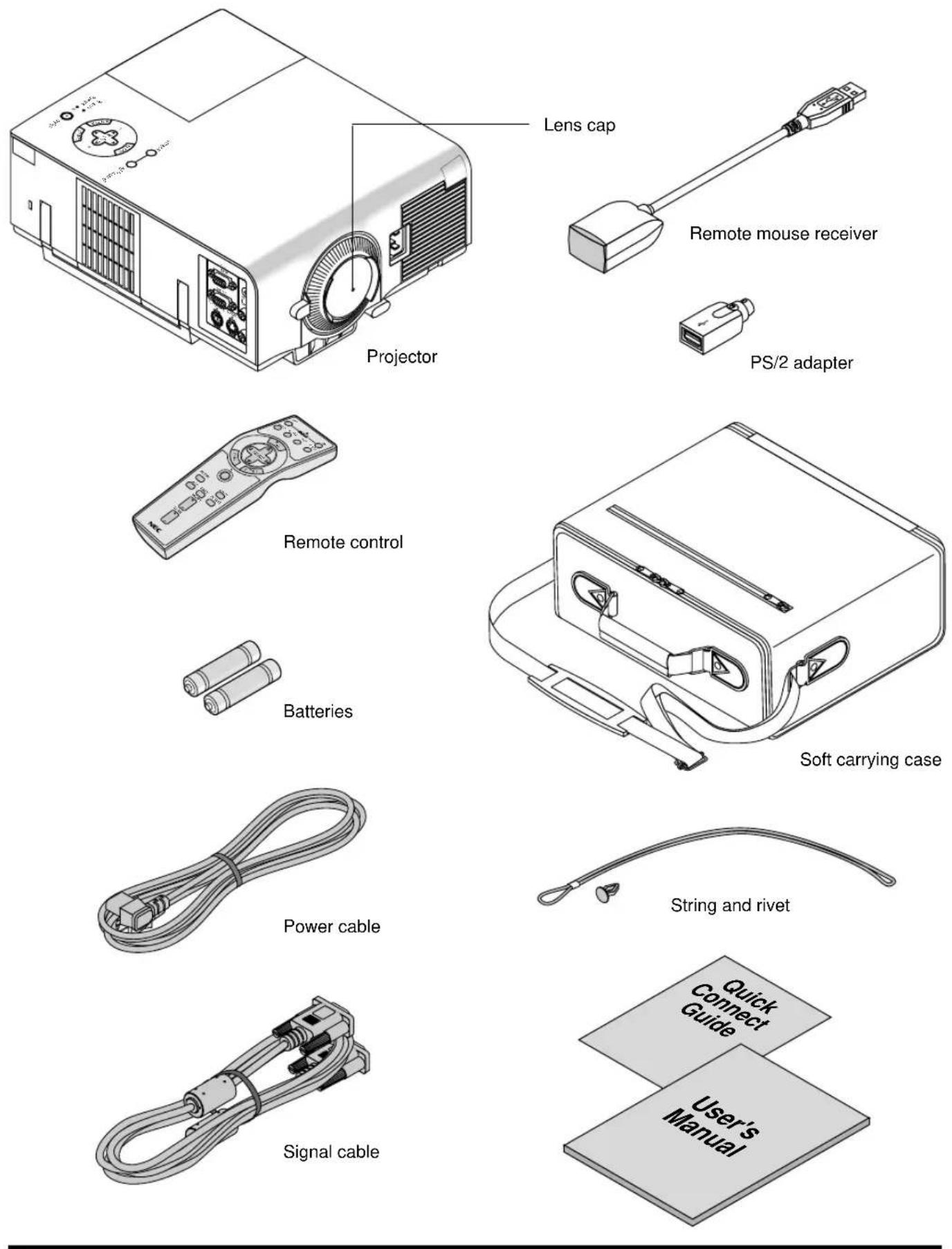
What's in the Box?
Make sure your box contains everything listed. If any pieces are missing, contact your dealer.
Please save the original box and packing materials if you ever need to ship your VT650 Projector.
Getting to Know Your VT650 Projector
Front/ Side Features
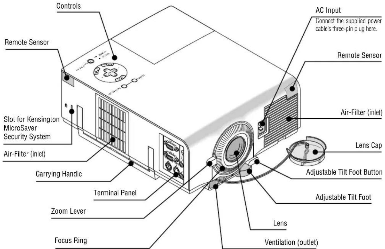
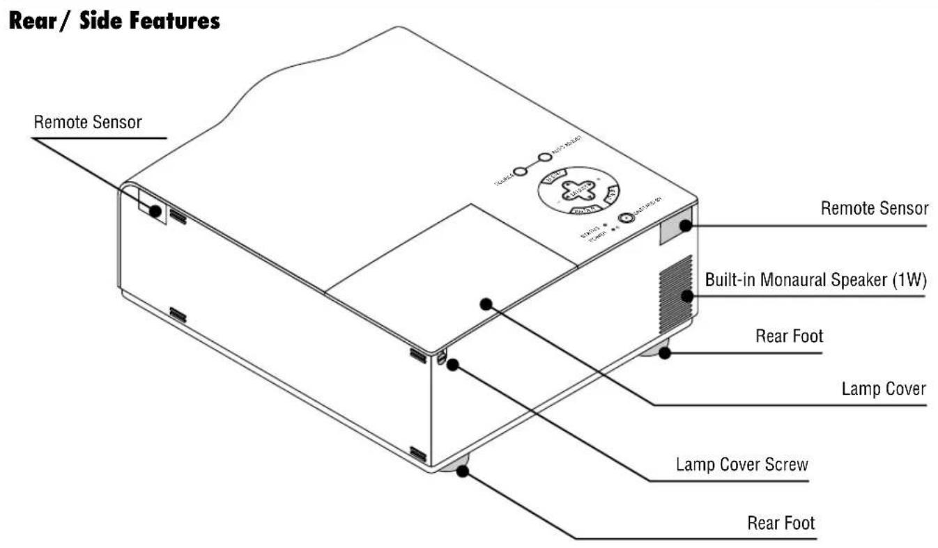
NOTE: Built-in Security Slot (
This security slot supports the MicroSaver ^® Security System. MicroSaver ^® is a registered trademark of Kensington Microwave Inc. The logo is trademarked and owned by Kensington Microwave Inc.
Carrying the Projector:
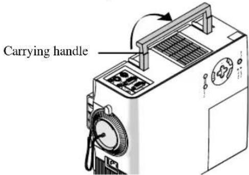
Raise the carrying handle up. Always carry your projector by the carrying handle.
NOTE: When moving the projector or when it is not in use, cover the lens with the lens cap.
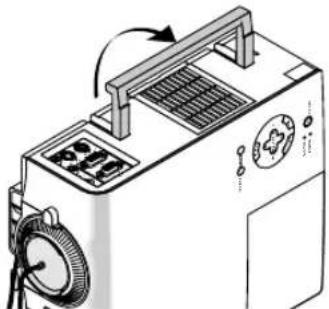
natural_image
Isometric line drawing of a portable electronic device with control panel and fan (no text or symbols)CAUTION
Do not put the projector on its side when the lamp is turned on.
Doing so may cause damage to the projector.
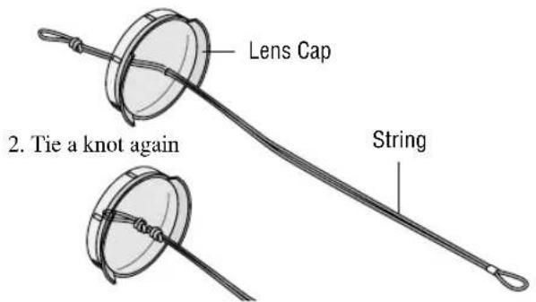
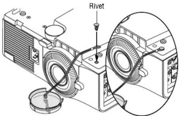
Attaching the lens cap to the bottom with the supplied string and rivet
- Thread the string through the hole on the lens cap and then tie a knot in the string.
- Use the rivet to attach the string to the bottom of the projector.
Top Features
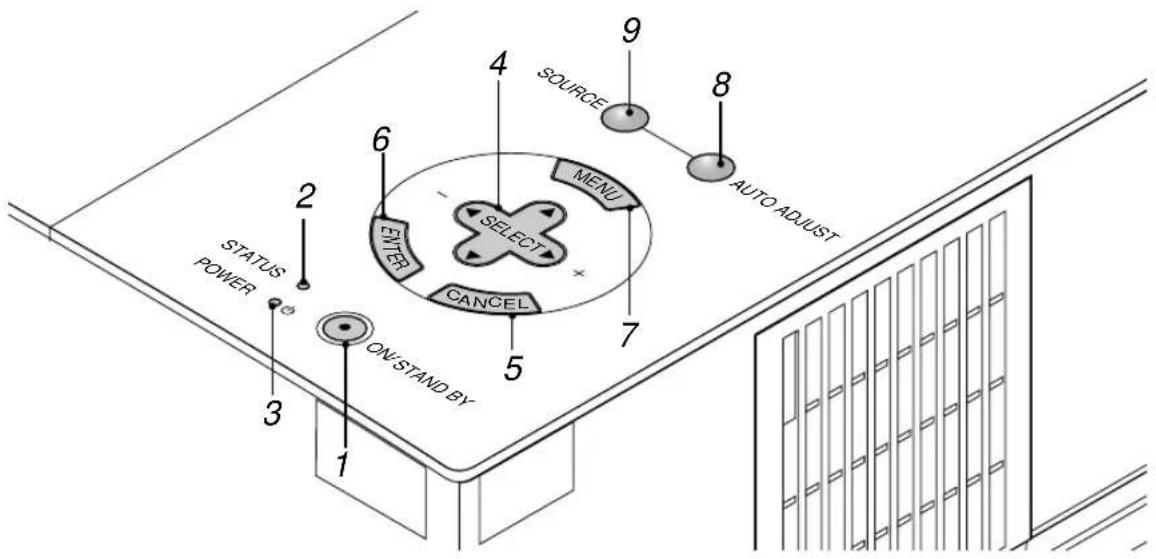
1. Power Button (ON / STAND BY)
Use this button to turn the power on and off when the power is supplied and the projector is in standby mode.
NOTE: To turn off the projector, press and hold this button for minimum of two seconds.
2. Status Indicator
When this is lit red continually, it's warning you that the projection lamp has exceeded 2000 hours (up to 3000 hours in Eco mode) of service. After this light appears, it is advisable to replace the projection lamp as soon as possible. (See page E-38). In addition the message "The lamp has reached the end of its usable life. Please replace the lamp." appears each time the projector is turned on until the lamp is replaced. If this light blinks red rapidly, it indicates that the lamp cover or filter cover is not attached properly or the projector is overheated. See the Power / Status Light Messages on page E-40 for more details.
3. Power Indicator (⏻)
When this indicator is green, the projector is on; when the indicator is orange, it is in standby mode.
4. Select (▲▼◀▶ / (+) (-) Buttons
▲▼: Use these buttons to select the menu of the item you wish to adjust.
◀▶ Use these buttons to change the level of a selected menu item.
When an image is magnified, these buttons can be used to move the image on screen.
5. Cancel Button
Press this button to exit the menu. While you are in the adjustment or setting menu, pressing this button will return to the previous menu.
6. Enter Button
Executes your menu selection and activates items selected from the menu.
7. Menu Button
Displays the menu.
8. Auto Adjust Button
Use this button to adjust Position-H/V and Pixel Clock/Phase for an optimal picture. Some signals may not be displayed correctly or take time to switch between sources.
9. Source Button
Use this button to select a video source such as a PC, VCR or DVD player.
Each time this button is pressed, the input source will change as follows:
$$ \rightarrow \mathrm{RGB} \rightarrow \text { Video } \rightarrow \mathrm{S-Video} \rightarrow \mathrm{RGB} \dots $$
If no input signal is present, the input will be skipped.
Terminal Panel Features
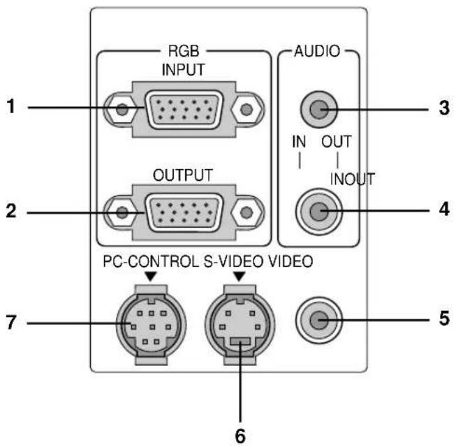
1. RGB Input Connector(Mini D-Sub 15 pin)
Connect your PC or other RGB equipment. Use the supplied signal cable to connect to a PC.
2. RGB Monitor Output Connector (Mini D-Sub 15 pin)
You can use this connector to loop your computer image to an external monitor from the RGB input source.
3. Audio Input / Output Mini Jack
This is where you connect audio output from your computer. Or connect additional external speakers here to listen to audio coming from your Video or S-Video input.
4. Audio Input / Output Connector (RCA)
This is where you connect audio output from a VCR, DVD player, or laser disc player. Or connect additional external speakers to listen to audio coming from your RGB source.
NOTE: Either connector 3 or 4 can be used for input or output, however they cannot both be used for input simultaneously. It can damage your equipment.
5. Video Input (RCA)
Connect a VCR, DVD player, laser disc player, or document camera here to project video.
6. S-Video Input Port (Mini DIN 4 Pin)
Connect the S-Video input from an external source like a VCR.
7. PC Control Port (Mini DIN 8 Pin)
Use this port to connect your PC to control your projector. This enables you to use your PC and serial communication protocol to control the projector. If you are writing your own program, typical PC control codes are on page E-45.
Remote Control Features
NOTE: If you are using a Macintosh computer, you can click either the right-click or left-click button to activate the mouse.
1. Infrared Transmitter
Direct the remote control toward the remote sensor on the projector cabinet.
2. LED
Flashes when any button is pressed.
3. Power ON Button
If the main power is applied, you can use this button to turn your projector on.
4. Power OFF Button
If the main power is applied, you can use this button to turn your projector off.
NOTE: To turn off the projector, press and hold the POWER OFF button for a minimum of two seconds.
5. VIDEO Button
Press this button to select a video source from a VCR, DVD player, laser disc player or document camera.
6. S-VIDEO Button
Press this button to select an S-Video source from a VCR.
7. RGB Button
Press this button to select an RGB source from computer or component equipment connected to your RGB port.
8. Auto Adjust Button
Use this button to adjust Position-H/V and Pixel Clock/Phase for an optimal picture. Some signals may not be displayed correctly, or in some cases it may take some time for a source to switch between sources.
9. Menu Button
Displays the menu.
10. Select (▲▼◀▶/ (mouse) Buttons
When you are in the Computer mode, these buttons work as a computer mouse. When you are in the Projector mode, which is indicated by lighting the PJ button:
▲▼: Use these buttons to select the menu of the item you wish to adjust. ◀▶ Use these buttons to change the level of a selected menu item.
11. Enter (Left click) Button
When you are in the Computer mode, this button works as the mouse left button.
When you are in the Projector mode, which is indicated by lighting the PJ button:
Use this button to enter your menu selection. It works the same way as the "Enter" button on the cabinet.
12. Cancel (Right click) Button
When you are in the Computer mode, this button works as the mouse right button.
When you are in the Projector mode, which is indicated by lighting the PJ button:
Press this button to exit "Menus". It works the same way as the "Cancel" button on the cabinet.
Remote Control
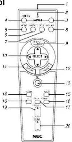
13. PJ Button
Press this button to switch the Select, Cancel, and Enter buttons between the Projector mode (lit red) and the Computer mode. Press this button or any one of the Power ON/OFF Menu, Help and Magnify buttons to switch to the Projector mode and the PJ button lights red. To switch back to the Computer mode, press the PJ button again.
14. Picture Button
Press this button to display the Picture adjustment window. Each time this button is pressed, the current picture adjustment item will change as follows:
→ Brightness Contrast Color Hue Sharpness
Unavailable items will be skipped.
15. Aspect Button
Press this button to display the Aspect Ratio select window. Each time this button is pressed, the current aspect ratio will change as follows:
Normal Zoom Wide Zoom Cinema
You can also select the aspect ratio by using the Select ◄ or ▶ button. If no adjustments are performed within 3 seconds, the Aspect Ratio select window will disappear. (See also page E-32.)
16. Help Button
Provides information about the current signal and the status of the projector.
17. Freeze Button
This button will freeze a picture. Press again to resume motion.
18. Picture Mute Button
This button turns off the image and sound for a short period of time. Press again to restore the image and sound.
19. Magnify Button
Use this button to adjust the image size up to 400%.
20. Volume Button
Press (+) to increase the volume and (−) to decrease it.
NOTE: The default is the Computer mode, which allows you to use the Select, Cancel, and Enter buttons as your computer mouse. When the Power ON/OFF, MENU, HELP or MAGNIFY button is pressed, the PJ button lights red to indicate that you are in the Projector mode. If no buttons are pressed within 10 seconds, the light goes out and the Projector mode is canceled.
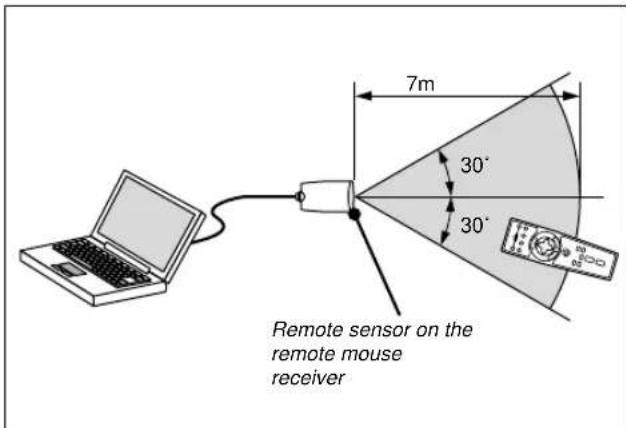
Operating Range Remote Control Battery Installation
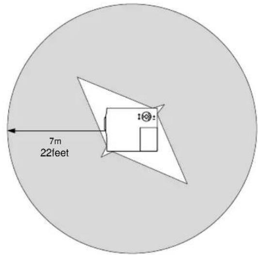
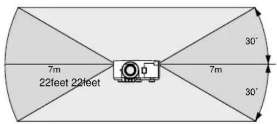
- Push to open the battery cover.
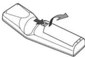
natural_image
Line drawing of a remote control with a scroll wheel (no text or symbols)- Remove both old batteries and install new ones (AA). Ensure that you have the batteries' polarity (+/-) aligned correctly.
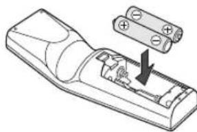
natural_image
Diagram of a remote control device with battery pack and internal components (no text or symbols)- Put the battery cover back on.
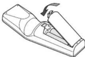
natural_image
Line drawing of a mechanical device with a handle and base plate (no text or symbols)Do not mix different types of batteries or new and old batteries.
Remote Control Precautions
- Handle the remote control carefully.
- If the remote control gets wet, wipe it dry immediately.
- Avoid excessive heat and humidity.
- If you will not be using the remote control for a long time, remove the batteries.
Note on Remote Control Operation:
Pressing and holding the Select (▲, ▼, ◀) ▶Mouse buttons while installing new batteries may cause malfunction or no operation.
Should this happen, remove the batteries and then install them again without touching the Select/Mouse button.
NOTE: Do not change the settings of the function (DIP) switches. There are two switches on the bottom of the battery case. For normal operation, these function switches are not used. Be sure to leave the No.1 switch at its original factory setting(OFF). Do not change the setting of the No.1 switch. Failure to do so will cause incorrect movement in Select (▲, ▼, ◀) ▶Mouse buttons.
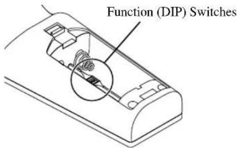
Using Remote Mouse Receiver
The remote mouse receiver enables you to operate your computer's mouse functions from the remote control (Computer mode). It is a great convenience for clicking through your computer-generated presentations. To return to the Projector mode, press the PJ button (lit red).
Connecting the remote mouse receiver to your computer
If you wish to use the remote mouse function, connect the mouse receiver and computer.
The mouse receiver can be connected directly to the computer using the USB terminal.
To connect it to the computer using the mouse (PS/2) terminal, do so using the PS/2 adapter.
NOTE: Depending on the type of connection or OS installed on your computer, you may have to restart your computer or change your computer settings.
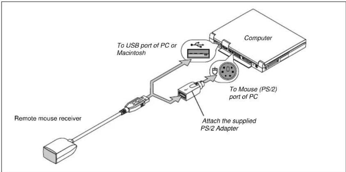
flowchart
graph TD
    A["Computer"] -->|To USB port of PC or Macintosh| B["Remote mouse receiver"]
    B --> C["Attach the supplied PS/2 Adapter"]
    C --> D["To Mouse (PS/2) port of PC"]
    D --> E["USB port"]
When connecting using the USB terminal
For PC, the mouse receiver can only be used with a Windows 98, Windows ME or Windows 2000 operating system.
NOTE:
- Wait at least 5 seconds after disconnecting the mouse receiver before reconnecting it and vice versa. The computer may not identify the mouse receiver if it is repeatedly connected and disconnected in rapid intervals.
- When using the PS/2 adapter, be sure to attach the PS/2 adapter to the remote mouse receiver first. Do not connect or disconnect the USB connector of the remote mouse receiver with the PS/2 adapter on the mouse (PS/2) port of your PC. Doing so can result in your PC failing to detect the remote mouse receiver.
When operating a computer via the remote mouse receiver
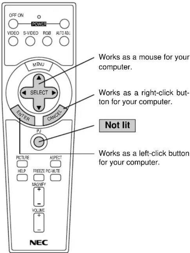
Switching Operation Mode between Computer and Projector
The SELECT, ENTER, and CANCEL buttons shown on the drawing work as a computer mouse in the Computer mode. In the Computer mode the PJ button is not lit.
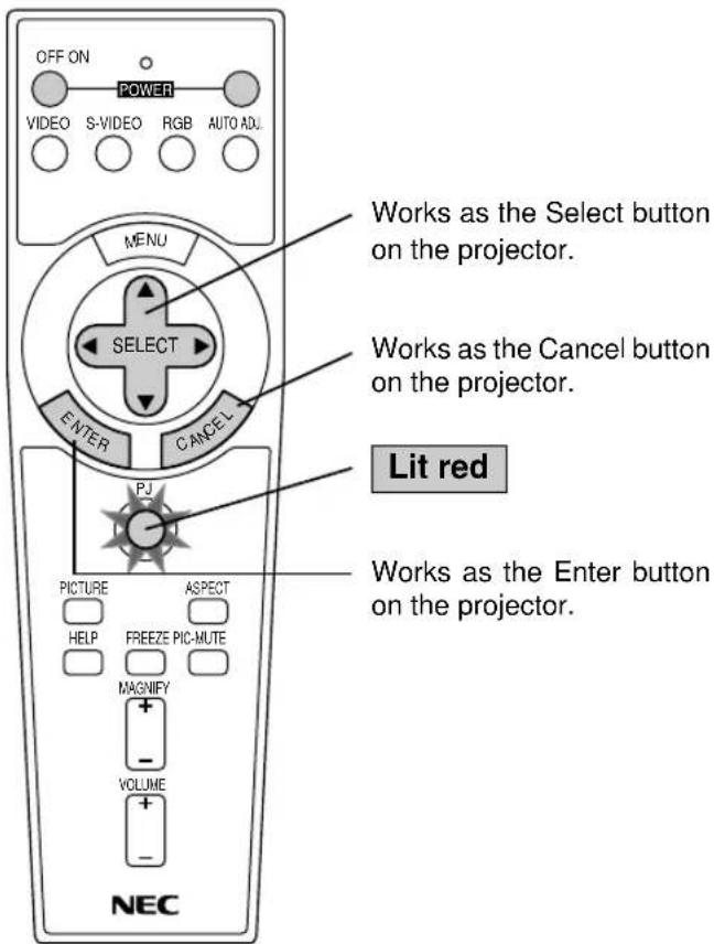
- When any one of the POWER ON, OFF, MENU, HELP, or MAGNIFY button is pressed, the PJ button lights red to indicate that you are in the Projector mode, which allows the projector menu operation using the SELECT, ENTER or CANCEL buttons.
- If no buttons are pressed within 10 seconds, the PJ button's light goes out to indicate that you are in the Computer mode. To enable the projector menu operation again, press the PJ button to light red.
- When the PJ button is lit, if you want to use the mouse function immediately, press the PJ button to return to the Computer mode (not lit).
[Computer mode]
[Projector mode]
During Computer mode:
During Computer mode by pressing the ENTER button for 1.5 seconds or more then releasing, the drag mode is set and the drag operation can be performed simply by pressing the SELECT (▲, ▼, ◀) ▶(mouse) button. To cancel the drag mode, press the ENTER (left click) button again or press the CANCEL (right click) button.
Note on Operating Your PC with the Remote Control
If no button operation is made for 60 seconds or more, the SELECT( ▲ , ▼ , ◀/ mouse) button operations will cease to operate.
This is not a malfunction, rather it is a feature used to prolong battery power.
To cancel this feature, press the CANCEL button.
2. INSTALLATION
This section describes how to set up your VT650 projector and how to connect video and audio sources.
Setting up Your Projector
Your VT650 Projector is simple to set up and use. But before you get started, you must first:
-
Determine the image size.
-
Set up a screen or select a non-glossy white wall onto which you can project your image.
Carrying the Projector: Always carry your projector by the handle. Ensure that the power cable and any other cables connecting to video sources are disconnected before moving the projector.
When moving the projector or when it is not in use, cover the lens with the lens cap.
Selecting a Location
The further your projector is from the screen or wall, the larger the image. The minimum size the image can be is approximately 25" (0.64 m) measured diagonally when the projector is roughly 3.5 feet (1.1 m) from the wall or screen. The largest the image can be is 300" (7.6 m) when the projector is about 36.6 feet (11.2 m) from the wall or screen.
Using a Tabletop or Cart
-
Place your projector on a flat level surface at the optimal distance from the screen or wall so you realize the size image you want. (Avoid having bright room lighting or sun light directly on the screen or wall where you'll be projecting the image.)
-
Connect the power cable, remove the lens cap and turn the projector on. (If no input signal is available, the projector will display a background image.)
-
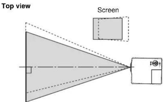
Ensure that the projector is square to the screen.
-
Move the projector left or right to center the image horizontally on the screen.
-
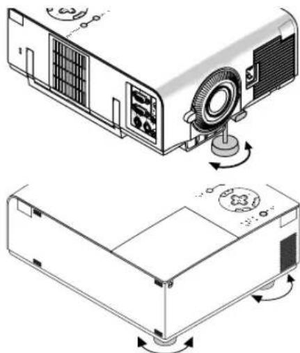
To center the image vertically, lift the front edge of the projector and press the One-Touch Tilt button on the front side of the projector to release the Front Adjustable foot.
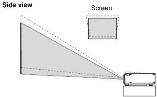
(There is approximately 10 degrees of up and down adjustment for the front of the projector.)
Adjusting the Tilt Foot
1) Press and hold the Tilt button on the front of the projector.
2) Lift the front edge of the projector to the height you want, and release the button to lock the Adjustable Tilt Foot.
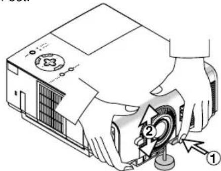
To fine-tune the image's position vertically on the screen, rotate the foot. Each of the rear feet height can be changed up to 0.6" (4mm).
natural_image
Technical illustration of a projector with fan and control panel, shown in two views (top: open, bottom: closed) with no visible text or symbols.-
If the projected image does not appear square to the screen then use keystone correction for proper adjustment.
-
Adjust the size of the image using the Zoom lever on the lens.
Distance Chart
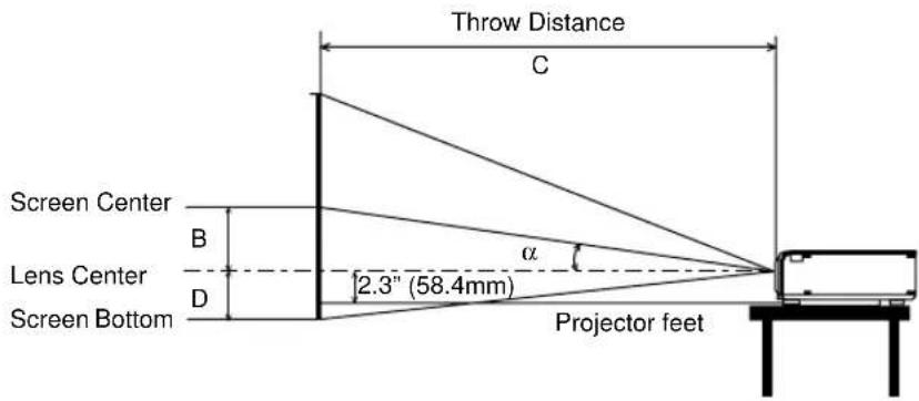
B = Vertical distance between lens center and screen center
C = Throw distance
D = Vertical distance between lens center and bottom of screen for desktop
α = Throw angle
Lens Offset 5.5mm
| Screen Size | B | C | D | α | |||||||||||
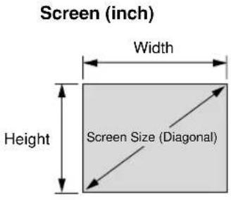
| Diagonal | Width | Height | wide | tele | wide | tele | |||||||||
| inch mm | inch mm in | ch mm inch | mm inch m | mm - inch mm | inch mm | degree - degree | |||||||||
| 25 | 635 20 508 | 15 381 6 153 | --- 42 107 | 7 1 38 | - 8.1 | ||||||||||
| 30 | 762 24 610 | 18 457 7 183 | 42 1077 | 51 1301 | 2 45 9.7 | - 8.0 | |||||||||
| 40 | 1016 32 813 | 24 610 10 | 244 57 1450 | - 69 1749 | 2 60 9.6 | - 8.0 | |||||||||
| 60 | 1524 48 1219 | 36 914 14 | 367 87 219 | - 104 264 | 5 4 91 | 9.5 | - 7.9 | ||||||||
| 67 | 1702 54 136 | 40 | 1021 16 409 | 97 2459 | - | 117 2959 | 4 | 101 9.5 | - 7.9 | ||||||
| 72 | 1829 58 146 | 43 | 1097 17 440 | 104 2645 | - | 125 3183 | 4 | 109 9.4 | - 7.9 | ||||||
| 80 | 2032 64 162 | 48 | 1219 19 489 | 116 2944 | - | 139 3542 | 5 | 121 9.4 | - 7.9 | ||||||
| 84 | 2134 67 170 | 50 | 1280 20 513 | 122 3094 | - | 146 3721 | 5 | 127 9.4 | - 7.9 | ||||||
| 90 | 2286 72 182 | 54 | 1372 22 550 | 131 3318 | - | 157 3990 | 5 | 136 9.4 | - 7.8 | ||||||
| 100 | 2540 80 203 | 60 | 1524 24 611 | 145 3691 | - | 175 4438 | 6 | 151 9.4 | - 7.8 | ||||||
| 120 | 3048 96 243 | 72 | 1829 29 733 | 175 4438 | - | 210 5335 | 7 | 181 9.4 | - 7.8 | ||||||
| 150 | 3810 120 304 | 890 | 2286 36 91 | 7 219 5559 | - | 263 6679 | 9 | 226 9.4 | - 7.8 | ||||||
| 180 | 4572 144 365 | 8 108 | 2743 43 | 100 263 6679 | - | 316 802 | 14 | 11 272 9.4 | - 7.8 | ||||||
| 200 | 5080 160 406 | 120 | 3048 48 | 222 292 7426 | - | 351 892 | 20 | 12 302 9.3 | - 7.8 | ||||||
| 210 | 5334 168 426 | 126 | 3200 51 | 1283 307 7800 | - | 369 936 | 8 | 12 317 9.3 | - 7.8 | ||||||
| 240 | 6096 | 192 | 4877 | 144 | 3658 | 58 | 1467 | 351 | 8920 | - | 422 | 10713 | 14 | 362 | 9.3 |
| 250 | 6350 | 200 | 5080 | 150 | 3810 | 60 | 1528 | 366 | 9294 | - | 439 | 11161 | 15 | 377 | 9.3 |
| 270 | 6858 | 216 | 5486 | 162 | 4115 | 65 | 1650 | 395 | 10041 | - | - | - | 16 | 407 | 9.3 |
| 300 | 7620 | 240 | 6096 | 180 | 4572 | 72 | 1833 | 439 | 11161 | - | - | - | 18 | 453 | 9.3 |
B = Vertical distance between lens center and screen center
C = Throw distance
D = Vertical distance between lens center and bottom of screen for desktop
α = Throw angle
NOTE: Distances may vary +/-5%.
Ceiling Installation
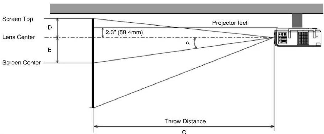
B = Vertical distance between lens center and screen center
C = Throw distance
D = Vertical distance between lens center and top of screen
α = Throw angle
Lens Offset 5.5mm
| Screen Size | B | C | D | α | |||||||||||||
| Diagonal | Width | Height | wide | tele | wide | tele | |||||||||||
| inch mm | inch mm | inch mm | inch mm | mm - inch mm | inch mm | degree - degree | |||||||||||
| 25 | 635 | 20 | 508 | 15 | 381 | 6 | 153 | - | - | - | 42 | 1077 | 1 | 38 | - | - | 8.1 |
| 30 | 762 | 24 | 610 | 18 | 457 | 7 | 183 | 42 | 1077 | - | 51 | 1301 | 2 | 45 | 9.7 | - | 8.0 |
| 40 | 1016 | 32 | 813 | 24 | 610 | 10 | 244 | 57 | 1450 | - | 69 | 1749 | 2 | 60 | 9.6 | - | 8.0 |
| 60 | 1524 | 48 | 1219 | 36 | 914 | 14 | 367 | 87 | 2197 | - | 104 | 2645 | 4 | 91 | 9.5 | - | 7.9 |
| 67 | 1702 | 54 | 1361 | 40 | 1021 | 16 | 409 | 97 | 2459 | - | 117 | 2959 | 4 | 101 | 9.5 | - | 7.9 |
| 72 | 1829 | 58 | 1463 | 43 | 1097 | 17 | 440 | 104 | 2645 | - | 125 | 3183 | 4 | 109 | 9.4 | - | 7.9 |
| 80 | 2032 | 64 | 1626 | 48 | 1219 | 19 | 489 | 116 | 2944 | - | 139 | 3542 | 5 | 121 | 9.4 | - | 7.9 |
| 84 | 2134 | 67 | 1707 | 50 | 1280 | 20 | 513 | 122 | 3094 | - | 146 | 3721 | 5 | 127 | 9.4 | - | 7.9 |
| 90 | 2286 | 72 | 1829 | 54 | 1372 | 22 | 550 | 131 | 3318 | - | 157 | 3990 | 5 | 136 | 9.4 | - | 7.8 |
| 100 | 2540 | 80 | 2032 | 60 | 1524 | 24 | 611 | 145 | 3691 | - | 175 | 4438 | 6 | 151 | 9.4 | - | 7.8 |
| 120 | 3048 | 96 | 2438 | 72 | 1829 | 29 | 733 | 175 | 4438 | - | 210 | 5335 | 7 | 181 | 9.4 | - | 7.8 |
| 150 | 3810 | 120 | 3048 | 90 | 2286 | 36 | 917 | 219 | 5559 | - | 263 | 6679 | 9 | 226 | 9.4 | - | 7.8 |
| 180 | 4572 | 144 | 3658 | 108 | 2743 | 43 | 1100 | 263 | 6679 | - | 316 | 8024 | 11 | 272 | 9.4 | - | 7.8 |
| 200 | 5080 | 160 | 4064 | 120 | 3048 | 48 | 1222 | 292 | 7426 | - | 351 | 8920 | 12 | 302 | 9.3 | - | 7.8 |
| 210 | 5334 | 168 | 4267 | 126 | 3200 | 51 | 1283 | 307 | 7800 | - | 369 | 9368 | 12 | 317 | 9.3 | - | 7.8 |
| 240 | 6096 | 192 | 4877 | 144 | 3658 | 58 | 1467 | 351 | 8920 | - | 422 | 10713 | 14 | 362 | 9.3 | - | 7.8 |
| 250 | 6350 | 200 | 5080 | 150 | 3810 | 60 | 1528 | 366 | 9294 | - | 439 | 11161 | 15 | 377 | 9.3 | - | 7.8 |
| 270 | 6858 | 216 | 5486 | 162 | 4115 | 65 | 1650 | 395 | 10041 | - | - | - | 16 | 407 | 9.3 | - | - |
| 300 | 7620 | 240 | 6096 | 180 | 4572 | 72 | 1833 | 439 | 11161 | - | - | - | 18 | 453 | 9.3 | - | - |
B = Vertical distance between lens center and screen center
C = Throw distance
D = Vertical distance between lens center and top of screen
α = Throw angle
WARNING
- Installing your projector on the ceiling must be done by a qualified technician. Contact your NEC dealer for more information.
* Do not attempt to install the projector yourself. - Only use your projector on a solid, level surface. If the projector falls to the ground, you can be injured and the projector severely damaged.
- Do not use the projector where temperatures vary greatly. The projector must be used at temperatures between 32^ (0^) and 95^ (35^) .
- Do not expose the projector to moisture, dust, or smoke. This will harm the screen image.
- Ensure that you have adequate ventilation around your projector so heat can dissipate. Do not cover the vents on the side or the front of the projector.
If your projector is mounted on the ceiling and your image is upside down, use the "Menu" and "Select" buttons on your projector cabinet or your remote control to correct the orientation. (See page E-35.)
Reflecting the Image
Using a mirror to reflect your projector's image enables you to enjoy a much larger image. Contact your NEC dealer if you need a mirror. If you're using a mirror and your image is inverted, use the "Menu" and "Select" buttons on your projector cabinet or your remote control to correct the orientation. (See page E-35.)
Wiring Diagram
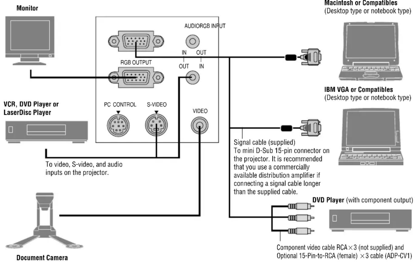
flowchart
graph TD
    A["Monitor"] --> B["RGB OUTPUT"]
    B --> C["PC CONTROL"]
    B --> D["S-VIDEO"]
    C --> E["VIDEO"]
    D --> E
    E --> F["Document Camera"]
    G["Macintosh or Compatibles (Desktop type or notebook type)"] --> H["IBM VGA or Compatibles (Desktop type or notebook type)"]
    I["IBM VGA or Compatibles (Desktop type or notebook type)"] --> J["Document Camera"]
    K["DVD Player (with component output)"] --> L["Component video cable RCA×3 (not supplied) and Optional 15-Pin-to-RCA (female) ×3 cable (ADP-CV1)"]
    M["Document Camera"] --> N["To video, S-video, and audio inputs on the projector."]
    O["Document Camera"] --> P["To video, S-video, and audio inputs on the projector."]
NOTE: When using with a notebook PC, be sure to connect between the projector and the notebook PC before turning on the power to the notebook PC. In most cases signal cannot be output from RGB output unless the notebook PC is turned on after connecting with the projector.
NOTE:
* If the screen goes blank while using your remote control, it may be the result of the computer's screen-saver or power management software.
* If you accidentally hit the POWER OFF button on the remote control, wait 60 seconds and then press the POWER ON button again to resume.
NOTE: If using video, S-video, or audio cables, the cables should be 3 m (9.8 feet) or shorter.
To connect SCART output (RGB)
Before connections: An exclusive SCART adapter (ADP-SC1) and a commercially available SCART cable are required for this connection.
NOTE: Audio signal is not available for this connection.
Video equipment such as DVD player
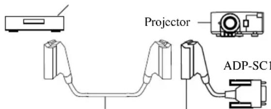
Commercially available SCART cable Female
- Turn off the power to the projector and your video equipment.
- Use the NEC ADP-SC1 SCART adapter and a commercially available SCART cable to connect the RGB input of your projector and a SCART output (RGB) of your video equipment.
- Turn on the power to the projector and your video equipment.
- Use the RGB button on the remote control to select the RGB input.
- Press the MENU button on the remote control to display the menu.
- From the Advanced menu, select [Projector Options] → [Setup] → [Signal Select RGB] → [Scart].
SCART is a standard European audio-visual connector for TVs, VCRs and DVD players. It is also referred to as Euro-connector.
NOTE: The ADP-SC1 SCART adapter is obtainable from your NEC dealer in Europe.
Contact your NEC dealer in Europe for more information.
Connecting Your PC
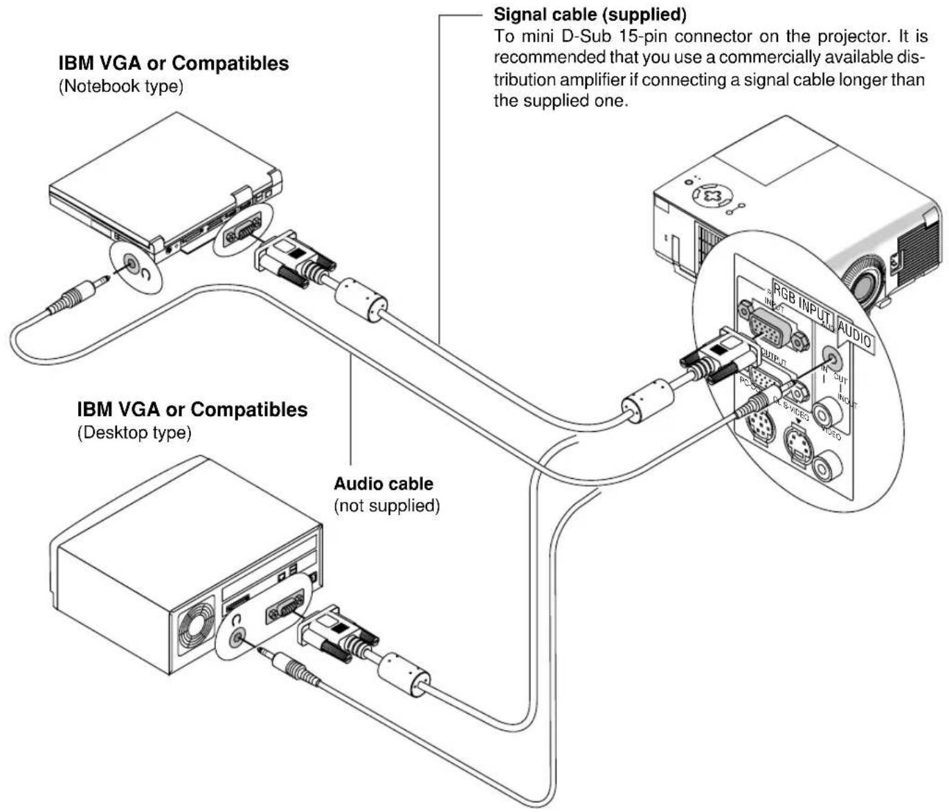
Connecting your PC to your VT650 projector will enable you to project your computer's screen image for an impressive presentation. To connect to a PC, simply:
- Turn off the power to your projector and computer.
- Use the supplied signal cable to connect your PC to the projector.
-
Turn on the projector and the computer.
-
If the projector goes blank after a period of inactivity, it may be caused by a screen saver installed on the computer you've connected to the projector.
Connecting Your Macintosh Computer
Macintosh (Notebook type)
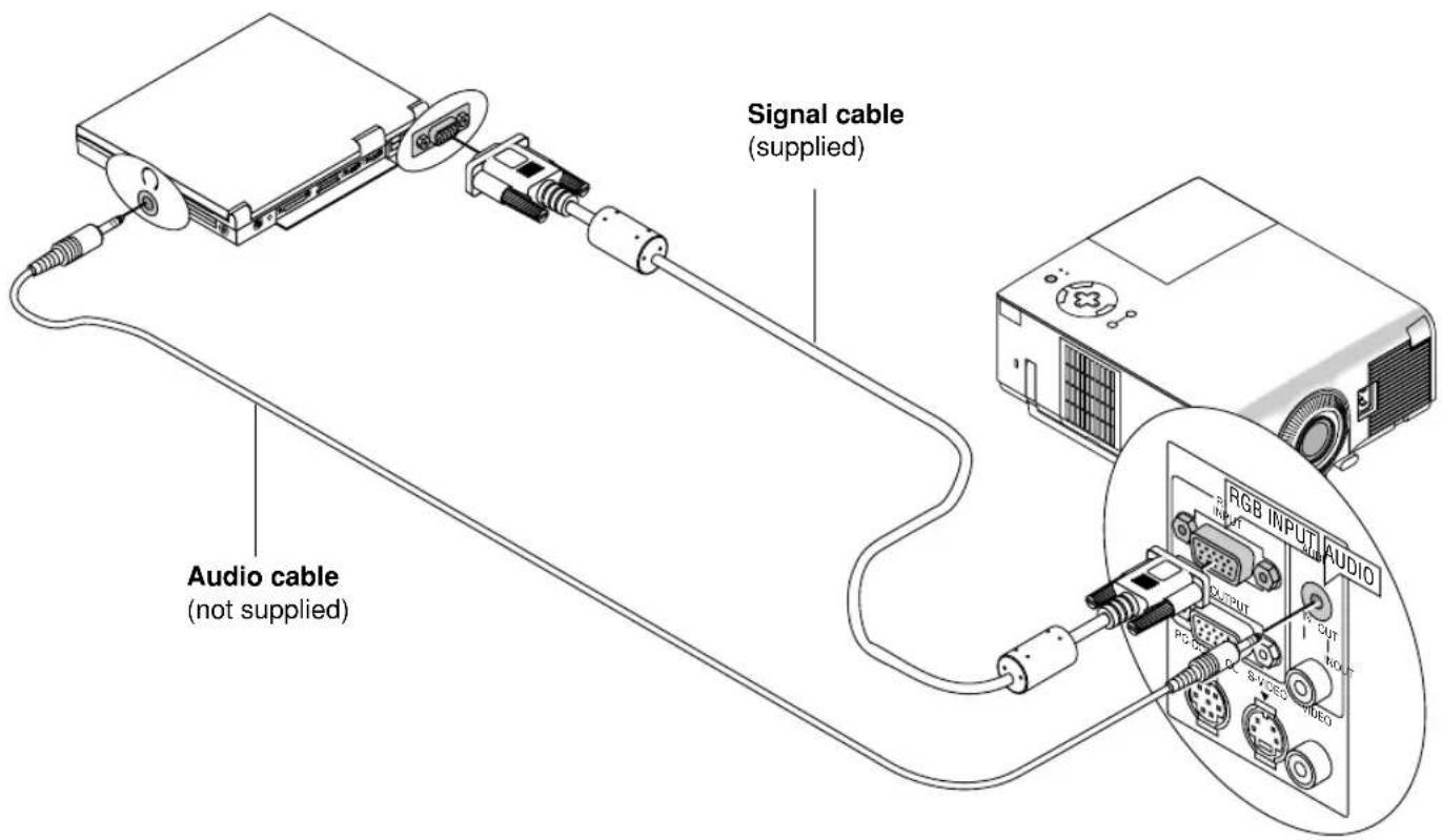
Macintosh (Desktop type)
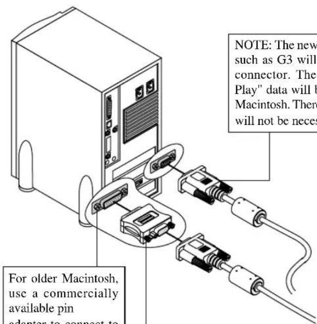
Pin adapter for Macintosh (not supplied)
To connect to a Macintosh, simply:
- Turn off the power to your projector and your Macintosh computer.
- Use the supplied signal cable to connect your Macintosh computer to the projector.
- Turn on the projector and the Macintosh computer.
Connecting an External Monitor
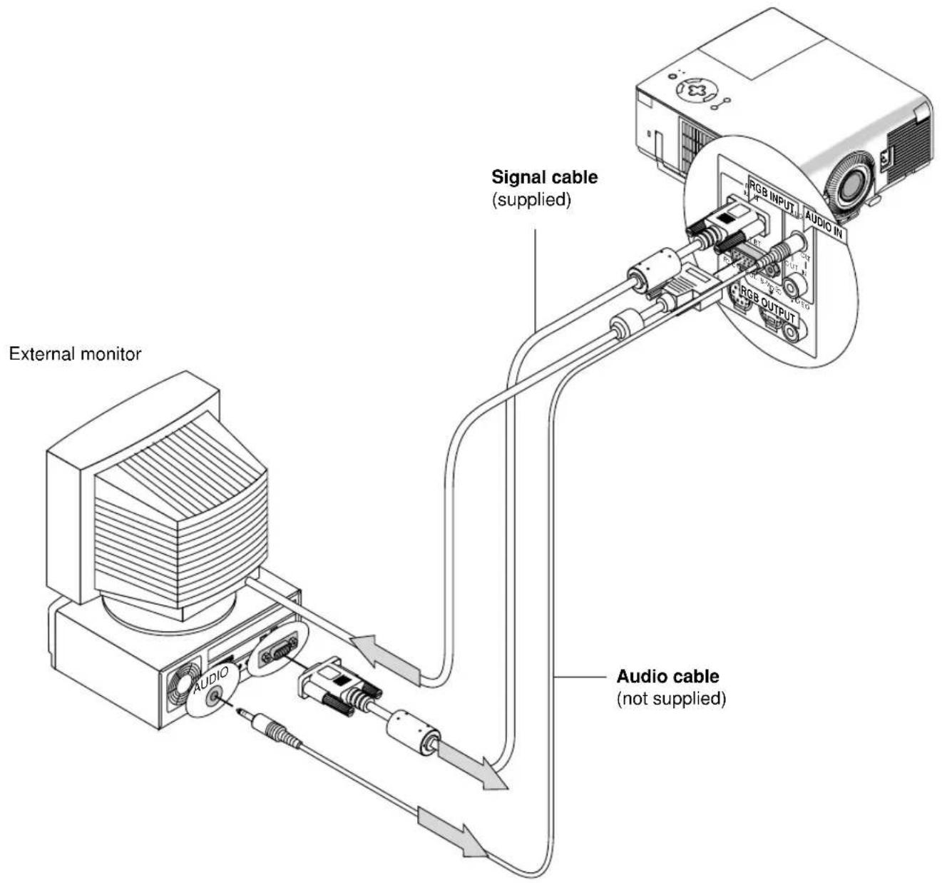
You can connect a separate, external monitor to your VT650 to simultaneously view on a monitor the image you're projecting. To do so:
- Turn off the power to your projector, monitor and computer.
- Use a 15-pin cable to connect your monitor to the RGB Monitor Output (Mini D-Sub 15 pin) connector on your projector.
- Turn on the projector, monitor and the computer.
NOTE: When the projector is turned off, RGB signal will not be sent to the external monitor.
Connecting Your DVD Player
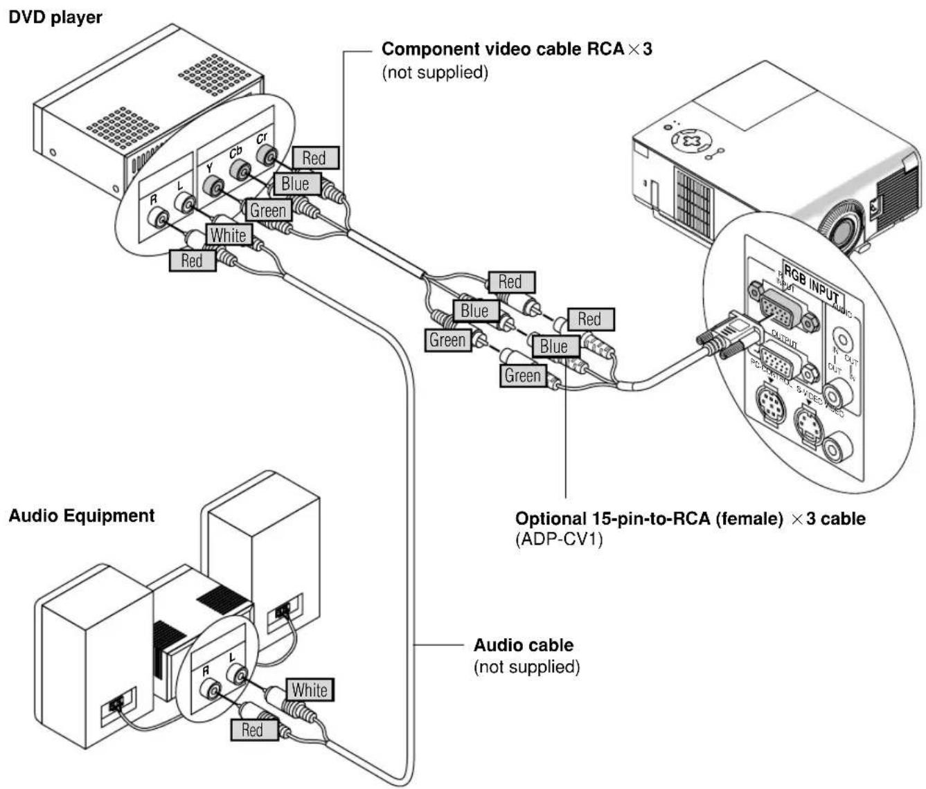
You can connect your projector to a DVD player with component outputs or Video output. To do so, simply:
-
Turn off the power to your projector and DVD player.
-
If your DVD player has the component video (Y,Cb,Cr) output, use a commercially available component video cable (RCA×3) and the optional 15-pin-to-RCA (female) ×3 cable to connect your DVD player to the RGB INPUT connector on the projector. For a DVD player without component video (Y,Cb,Cr) outputs, use common RCA cables (not provided) to connect a composite VIDEO output of the DVD player to the Video Input of the projector.
-
Turn on the projector and DVD player.
NOTE: Refer to your DVD player's owner's manual for more information about your DVD player's video output requirements,
Connecting Your VCR or Laser Disc Player
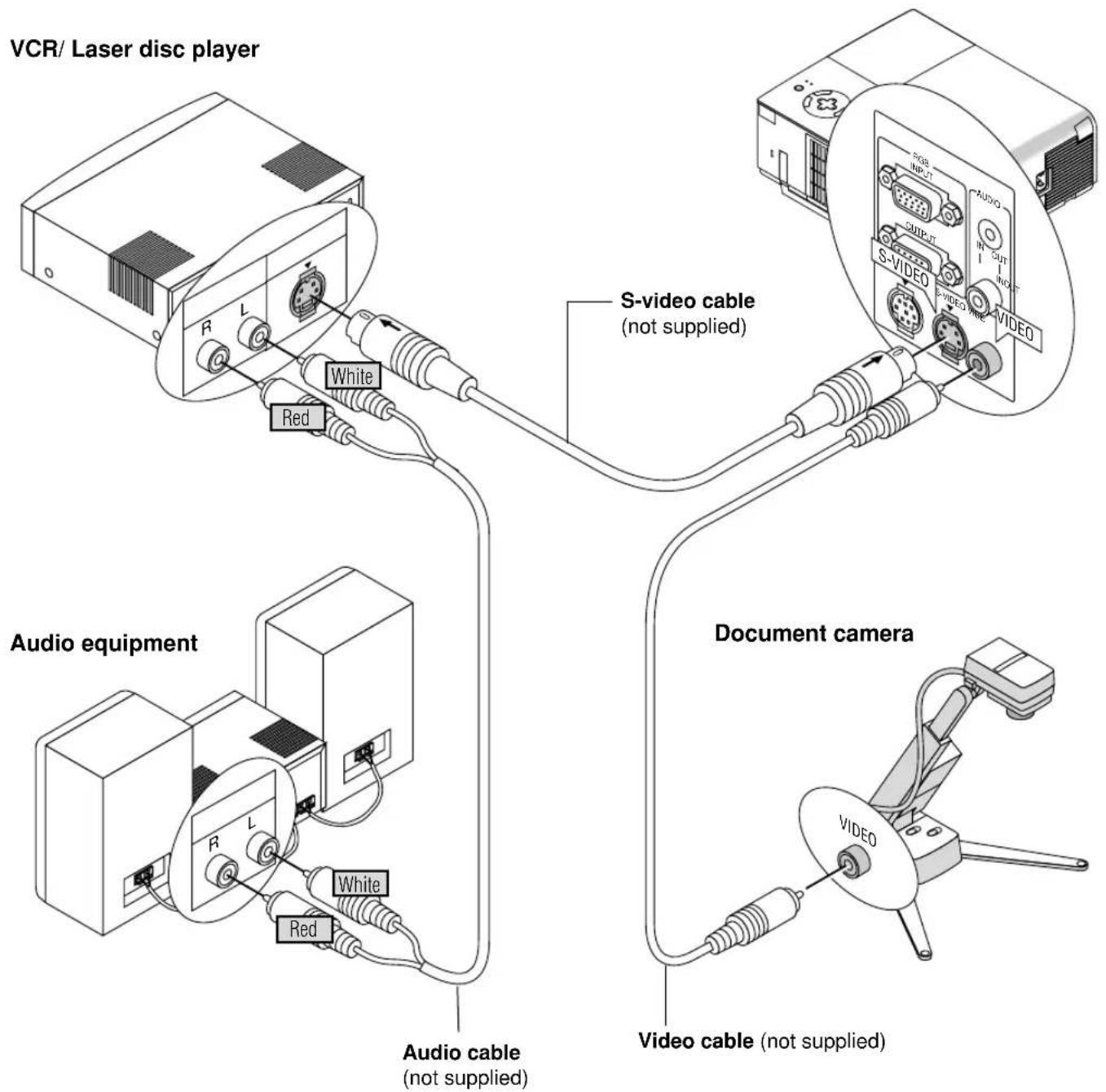
Use common RCA cables (not provided) to connect your VCR, laser disc player or document camera to your projector. To make these connections, simply:
-
Turn off the power to the projector and VCR, laser disc player or document camera.
-
Connect one end of your RCA cable to the video output connector on the back of your VCR or laser disc player, connect the other end to the Video input on your projector. Use an audio cable (not supplied) to connect the audio from your VCR or laser disc player to your audio equipment (if your VCR or laser disc player has this capability). Be careful to keep your right and left channel connections correct for stereo sound.
-
Turn on the projector and the VCR or laser disc player.
NOTE: Refer to your VCR or laser disc player owner's manual for more information about your equipment's video output requirements.
NOTE: The VT650 is not compatible with video decoded outputs of ISS-6020 and ISS-6010.
NOTE: An image may not be displayed correctly when a Video or S-Video source is played back in fast-forward or fast-rewind via a scan converter.
3. OPERATION
This section describes how to select a computer or video source, how to adjust the picture, and how to customize the menu or projector settings.
General Controls
Before you turn on your projector, ensure that the computer or video source is turned on and that your lens cap is removed.
1. Turn on the Projector
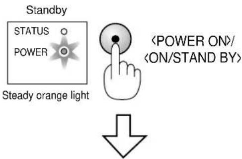
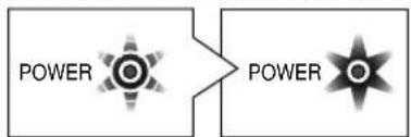
Plug the supplied power cable in the wall outlet. The projector will go into its standby mode and the power indicator will glow orange. Only after you press the "ON/STAND BY" button on the projector cabinet or the "POWER ON" button on the remote control will the power indicator turn to green and the projector become ready to use.
Indicator status when the projector is turned on:
Flashing green
light for one minute Steady green light
flowchart
graph LR
    A["POWER"] --> B["POWER"]
The STATUS indicator's light depends on the lamp mode.
NOTE: To turn the projector on by plugging in the power cable, use the menu and enable the "Auto Start" feature. (See page E-36.)
NOTE: Immediately after turning on the projector, screen flicker may occur. This is not a fault. Wait for 3 to 5 minutes until the lamp lighting is stabilized.
2. Select the Computer or Video Source
Press the Source button on the remote control or the projector cabinet to select "Video" (VCR, document camera, or laser disc player), "S-Video" or "RGB" (computer or DVD with component output) to display the image.
Or press the "Menu" button on the remote control or the cabinet and use the menu to select your video source: "Video", "S-Video" or "RGB".
3. Adjust the Image Size and the Focus
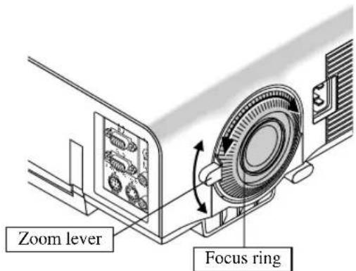
Use the Zoom lever to adjust the image size, then use the Focus ring to obtain the best focus.
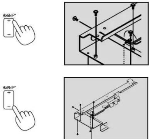
Use the “Magnify” button (+) or (-) on the remote control to make the image larger up to 400%.
See page E-27.
4. Turning off the Projector
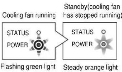
First press the "ON/STAND BY" button on the projector cabinet or the "POWER OFF" button on the remote control for a minimum of two seconds. The power indicator will glow orange. After the projector turns off, the cooling fans keep operating for 60 seconds.
Do not disconnect the power cable during this time. Then, unplug the power cable. The power indicator will go out.
Indicator status when the projector is turned off:

Press for a minimum of 2 seconds

flowchart
graph LR
    A["Cooling fan running"] --> B["Flashing green light"]
    C["Standby (cooling fan has stopped running)"] --> D["Steady orange light"]
    style A fill:#f9f,stroke:#333
    style C fill:#f9f,stroke:#333
    style B fill:#ccf,stroke:#333
    style D fill:#ccf,stroke:#333
IMPORTANT:
- The projector should be unplugged if it will not to be used for an extended period.
- To turn off the image and sound briefly (five minutes or less), use the "Picture Mute" button instead of turning the projector off and on.
- The projector will display a black, blue image or logo if no input signal is present.
- Do not turn the projector off and then immediately back on. The projector needs to cool for 60 seconds before it can be restarted.
CAUTION
Avoid displaying stationary images for a prolonged period of time.
Doing so can result in these images being temporarily sustained on the surface of the LCD panel.
If this should happen, continue to use your projector. The static background from previous images will disappear.
CAUTION
Do not turn off the main power or unplug the power cable from the wall outlet under any one of the following circumstances. Doing so can cause damage to the projector:
- Immediately after the power cable is plugged into the wall outlet (when the POWER indicator has not changed to a steady orange glow).
- Immediately after the cooling fan stops working (The cooling fan continues to work for 60 seconds after the projector is turned off with the POWER button).

About Startup Screen (Menu Language Select screen)
When you first turn on the projector, you will get the Startup screen. This screen gives you the opportunity to select one of the seven menu languages: English, German, French, Italian, Spanish, Swedish and Japanese.
To select a menu language, follow these steps:
- Use the ▲ or ▼ buttons to select one of the seven languages for the menu.
| Menu Language Select |
| Please select a menu language. English |
| Wählen Sie bitte die Menü Sprache aus. Deutsch |
| S'il vous plaît choisir la langue de menu. Français |
| Per favore di scegliere la lingua di menu. Italiano |
| Escoja por favor el idioma de menú. Español |
| Välj menyn språken. Svenska |
| メニュー言語を選択してください。日本語Select "UP", "DOWN" & "ENTER" |
-
Press the Enter button to execute the selection.
-
The Basic menu will be displayed in the language you have selected.
| Basic Menu | |
| Source Select | |
| Picture | |
| Volume | |
| Image Options | |
| Projector Options | |
| Information | |
To close the menu, press the Cancel button.
After this has been done, you can proceed to the advanced menu operation.
If you want, you can select the menu language later. See “Language” on page E-34.
Adjusting the Image Size and the Focus
To adjust the projector's focus or to zoom in and out use the Focus ring or Zoom lever on the lens.
Enlarging and Moving a Picture
You can enlarge the area you want up to 400 percent.
To do so:
Adjust the image size up to 400 percent.
While the picture is enlarged, you can move it using the "Select"
◀, ▶, ▲ or button.
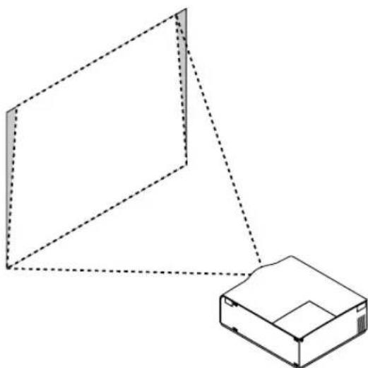
Geometrical Correction
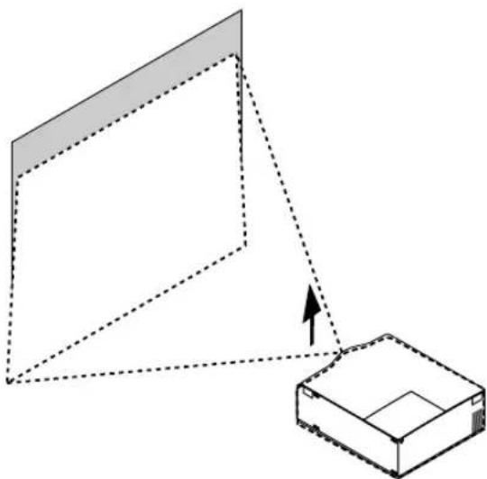
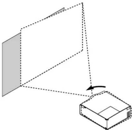
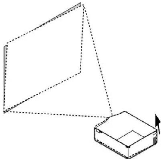
If the image is distorted or not displayed correctly on the screen, do the following.
natural_image
Diagram showing a 3D geometric shape with dashed lines and an arrow pointing to a rectangular box (no text or symbols)Raise the projector height using the adjustable tilt-foot.
natural_image
Diagram showing a 3D object with a shaded plane and a box, connected by dashed lines indicating rotation or transformation (no text or symbols)Rotate the projector to make the image square to the screen.
natural_image
Simple line drawing of a 3D box with an arrow indicating rotation or movement (no text or symbols)Each of the feet height can be changed up to 1 mm or at angles up to 1 degree.
natural_image
Isometric line drawing of a 3D geometric shape with dashed lines indicating hidden edges, next to a small rectangular box (no text or symbols)Use keystone correction for proper adjustment. See page E-31.
Using the Menus
-
Press the "Menu" button on the remote control or the projector cabinet to display the Menu.
-
Press the ▲▼ buttons on the remote control or the projector cabinet to highlight the menu for the item you want to adjust or set.
-
Press the ▶ button or the "Enter" button on the remote control or the projector cabinet to select a submenu or item.
-
Adjust the level or turn the selected item on or off by using "Select" ◀ or ▶ buttons on the remote control or the projector cabinet. The on-screen slide bar will show you the amount of increase or decrease.
-
The change is stored until you adjust it again.
CANCEL: Return to the previous screen.
- Repeat steps 2-5 to adjust an additional item, or press "Cancel" on the remote control or the projector cabinet to quit the menu display.
Menu Tree
Basic/ Advanced Menu
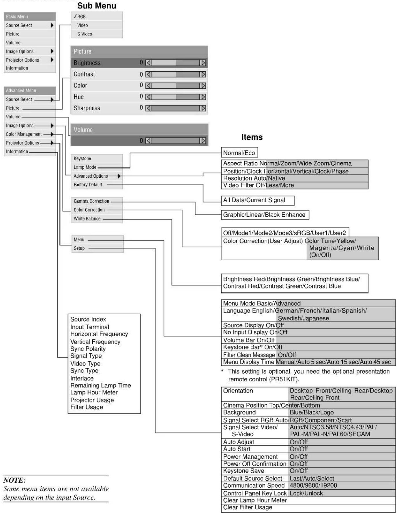
flowchart
graph TD
    A["Basic Menu"] --> B["Source Select"]
    A --> C["Picture"]
    A --> D["Volume"]
    A --> E["Image Options"]
    A --> F["Projector Options"]
    A --> G["Information"]
    H["Advanced Menu"] --> I["Source Select"]
    H --> J["Picture"]
    H --> K["Volume"]
    H --> L["Image Options"]
    H --> M["Color Management"]
    H --> N["Projector Options"]
    H --> O["Information"]
    P["Sub Menu"] --> Q["RGB"]
    P --> R["Video"]
    P --> S["S-Video"]
    T["Picture"] --> U["Brightness 0"]
    T --> V["Contrast 0"]
    T --> W["Color 0"]
    T --> X["Hue 0"]
    T --> Y["Sharpness 0"]
    Z["Volume"] --> AA["Normal/Eco"]
    Z --> AB["Aspect Ratio Normal/Zoom/Wide Zoom/Cinema"]
    Z --> AC["Position/Clock Horizontal/Vertical/Clock/Phase"]
    Z --> AD["Resolution Auto/Native"]
    Z --> AE["Video Filter Off/Less/More"]
    AF["Items"] --> AG["Keystone Lamp Mode Advanced Options Factory Default"]
    AF --> AH["Gamma Correction Color Correction White Balance"]
    AF --> AI["Menu Setup"]
    AJ["Items"] --> AK["Normal/Eco"]
    AJ --> AL["Aspect Ratio Normal/Zoom/Wide Zoom/Cinema"]
    AJ --> AM["Position/Clock Horizontal/Vertical/Clock/Phase"]
    AJ --> AN["Resolution Auto/Native"]
    AJ --> AO["Video Filter Off/Less/More"]
    AP["Items"] --> AP["Keystone Lamp Mode Advanced Options Factory Default"]
    AQ["Items"] --> AQ["Graphic/Linear/Black Enhance"]
    AR["Items"] --> AR["All Data/Current Signal"]
    AS["Items"] --> AS["Off/Mode1/Mode2/Mode3/sRGB/User1/User2"]
    AS --> AT["Color Correction(User Adjust) Color Tune/Yellow/Magenta/Cyan/White (On/Off)"]
    AU["Items"] --> AU["Brightness Red/Brightness Green/Brightness Blue/Contrast Red/Contrast Green/Contrast Blue"]
    AV["Items"] --> AV["Menu Mode Basic/Advanced"]
    AW["Items"] --> AW["Language English/German/French/Italian/Spanish/Swedish/Japanese"]
    AX["Items"] --> AX["Source Display On/Off"]
    AX --> AY["No Input Display On/Off"]
    AZ["Items"] --> AZ["Volume Bar On/Off"]
    BA["Items"] --> BB["Keystone Bar* On/Off"]
    BC["Items"] --> BC["Filter Clean Message On/Off"]
    BD["Items"] --> BD["Menu Display Time Manual/Auto 5 sec/Auto 15 sec/Auto 45 sec"]
    BE["* This setting is optional. you need the optional presentation remote control (PR51KIT)."]
    BF["Source Index Input Terminal Horizontal Frequency Vertical Frequency Sync Polarity Signal Type Video Type Sync Type Interlace Remaining Lamp Time Lamp Hour Meter Projector Usage Filter Usage"] --> BG
Menu Elements
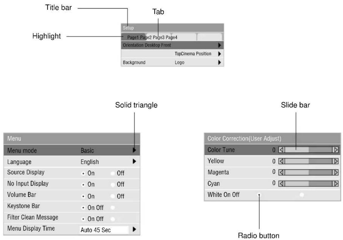
Menu windows or dialog boxes typically have the following elements:
Title bar: Indicates the menu title.
Highlight: Indicates the selected menu or item.
Solid triangle: Indicates further choices are available. A highlighted triangle indicates the item is active.
Tab: Indicates a group of features in a dialog box. Selecting on any tab brings its page to the front.
Radio button: Use this round button to select an option in a dialog box.
Slide bar: Indicates settings or the direction of adjustment.
Menu Descriptions & Functions
Source Select
| √RGB |
| Video |
| S-Video |
Enables you to select a video source such as a VCR, DVD player, laser disc player, computer or document camera depending on what is connected to your inputs. Press the "Select" button on the projector cabinet or your remote control to highlight the menu for the item you want to adjust.
Selects the computer connected to your RGB or component signal.
NOTE: An optional component cable (Component V or ADP-CV1 cable) is needed for a component signal.

- LIMITED WARRANTY
- GARANTIE LIMITEE
- BESCHRÄNKTE GARANTIE
- CAUTION
- WARNING
- DOC Compliance Notice
- GSGV Acoustic Noise Information Ordinance:
- RF Interference
- Important Safeguards
- Installation
- Power Supply
- Cleaning
- Lamp Replacement
- Fire and Shock Precautions
- TABLE OF CONTENTS
- INTRODUCTION
- INSTALLATION
- OPERATION
- MAINTENANCE
- TROUBLESHOOTING
- SPECIFICATIONS
- Introduction to the VT650 Projector
- Congratulations on Your Purchase of The VT650 Projector
- Features you'll enjoy:
- Getting Started
- What's in the Box?
- Getting to Know Your VT650 Projector
- Front/ Side Features
- NOTE: Built-in Security Slot (
- Carrying the Projector:
- Attaching the lens cap to the bottom with the supplied string and rivet
- Top Features
- Power Button (ON / STAND BY)
- Status Indicator
- Power Indicator (⏻)
- Select (▲▼◀▶ / (+) (-) Buttons
- Cancel Button
- Enter Button
- Menu Button
- Auto Adjust Button
- Source Button
- Terminal Panel Features
- RGB Input Connector(Mini D-Sub 15 pin)
- RGB Monitor Output Connector (Mini D-Sub 15 pin)
- Audio Input / Output Mini Jack
- Audio Input / Output Connector (RCA)
- Video Input (RCA)
- S-Video Input Port (Mini DIN 4 Pin)
- PC Control Port (Mini DIN 8 Pin)
- Remote Control Features
- Infrared Transmitter
- LED
- Power ON Button
- Power OFF Button
- VIDEO Button
- S-VIDEO Button
- RGB Button
- Menu Button
- Select (▲▼◀▶/ (mouse) Buttons
- Enter (Left click) Button
- Cancel (Right click) Button
- PJ Button
- Picture Button
- Aspect Button
- Help Button
- Freeze Button
- Picture Mute Button
- Magnify Button
- Volume Button
- Operating Range Remote Control Battery Installation
- Remote Control Precautions
- Note on Remote Control Operation:
- Using Remote Mouse Receiver
- Connecting the remote mouse receiver to your computer
- When connecting using the USB terminal
- NOTE:
- Switching Operation Mode between Computer and Projector
- During Computer mode:
- Note on Operating Your PC with the Remote Control
- Setting up Your Projector
- Selecting a Location
- Using a Tabletop or Cart
- Adjusting the Tilt Foot
- Distance Chart
- Lens Offset 5.5mm
- Ceiling Installation
- Reflecting the Image
- To connect SCART output (RGB)
- Connecting Your PC
- Connecting Your Macintosh Computer
- Macintosh (Notebook type)
- Macintosh (Desktop type)
- To connect to a Macintosh, simply:
- Connecting an External Monitor
- Connecting Your DVD Player
- Connecting Your VCR or Laser Disc Player
- General Controls
- Turn on the Projector
- Select the Computer or Video Source
- Adjust the Image Size and the Focus
- Turning off the Projector
- IMPORTANT:
- About Startup Screen (Menu Language Select screen)
- To select a menu language, follow these steps:
- Adjusting the Image Size and the Focus
- Enlarging and Moving a Picture
- Geometrical Correction
- Using the Menus
- Menu Tree
- Menu Elements
- Menu Descriptions & Functions
- Source Select
- Picture
- Volume
- Image Options
- Keystone
- Lamp Mode
- Advanced Options (Advanced mode)
- Aspect Ratio
- Factory Default
- Color Management
- Gamma Correction (Advanced mode)
- Gamma Correction
- Color Correction (Advanced mode)
- User Adjust
- White Balance (Advanced mode)
- Projector Options
- Menu
- Setup
- To lock the cabinet buttons:
- To unlock the cabinet buttons:
- Information
- Replacing the Lamp
- To replace the lamp:
- Cleaning or Replacing the Filters
- Model Number VT650
- Optical
- Electrical
- Mechanical
- Cabinet Dimensions
- D-Sub Pin Assignments
- Mini D-Sub 15 Pin Connector
- PC Control Codes
- Cable Connection
Brand : NEC
Model : VT650
Category : Video projector