
NC800C - Projector NEC - Free user manual and instructions
Find the device manual for free NC800C NEC in PDF.


| Product Type | Digital Cinema Projector |
| Resolution | 2048 x 1080 (DLP Cinema 3-chip) |
| Lamp Type | 1.25 kW Xenon lamp |
| Contrast Ratio | 200:1 or higher |
| Screen Size | Up to 8 m wide (depends on lens and setup) |
| Dimensions (W x D x H) | 670 mm x 826 mm x 423 mm (excluding protrusions) |
| Weight | 66 kg (excluding lens) |
| Power Supply | AC100-120V 50/60Hz (12A max) or AC200-240V 50/60Hz (8.5A max) |
| Power Consumption | 1.2 kW – 1.44 kW (100-120V), 1.7 kW (200-240V) |
| Lens Adjustment | Motorized zoom, focus, shift (vertical/horizontal), and douser |
| Signal Inputs | 2x HDSDI (BNC), 2x DVI-D (24-pin) |
| Control Interfaces | RS-232C, LAN (RJ-45) x2, USB (type A), GPIO (D-Sub 37-pin), PC card slot |
| Cooling | Forced air with dust filter |
| Noise Level | Less than 45 dB (minimum brightness mode) |
| Installation Orientations | Desktop front/rear, Ceiling front/rear |
| Operating Environment | Temperature: 5–35°C, Humidity: 10–85% (non-condensing) |
| Safety Features | High-pressure lamp warning, automatic cooling after shutdown, over-temperature protection |
| Cleaning | Cabinet: damp cloth with mild detergent; Lens: blower or lens paper |
| Accessories | Remote control (RD-371E), batteries, remote cables, lens holder, power cord, user manual |
Frequently Asked Questions - NC800C NEC
User questions about NC800C NEC
0 question about this device. Answer the ones you know or ask your own.
Ask a new question about this device
Download the instructions for your Projector in PDF format for free! Find your manual NC800C - NEC and take your electronic device back in hand. On this page are published all the documents necessary for the use of your device. NC800C by NEC.
USER MANUAL NC800C NEC
natural_image
Black NEC cinema projector with green lens and control panel (no visible text or symbols on body)NEC Viewtechnology, Ltd.
WARNING
TO PREVENT FIRE OR SHOCK HAZARDS, DO NOT EXPOSE THIS UNIT TO RAIN OR MOISTURE. ALSO DO NOT USE THIS UNIT'S POLARIZED PLUG WITH AN EXTENSION CORD RECEPTACLE OR OTHER OUTLETS, UNLESS THE PRONGS CAN BE FULLY INSERTED. REFRAIN FROM OPENING THE CABINET AS THERE ARE HIGH-VOLTAGE COMPONENTS INSIDE. REFER SERVICING TO QUALIFIED SERVICE PERSONNEL.
CAUTION

RISK OF ELECTRIC SHOCK DO NOT OPEN

CAUTION
TO REDUCE THE RISK OF ELECTRIC SHOCK, DO NOT OPEN COVER. NO USER-SERVICEABLE PARTS INSIDE. REFER SERVICING TO QUALIFIED SERVICE PERSONNEL.

This symbol warns the user that uninsulated voltage within the unit may have sufficient magnitude to cause electric shock. Therefore, it is dangerous to make any kind of contact with any part inside of this unit.

This symbol alerts the user that important literature concerning the operation and maintenance of this unit has been included. Therefore, it should be read carefully in order to avoid any problems.
DOC compliance Notice
This Class A digital apparatus meets all requirements of the Canadian Interference-Causing Equipment Regulations.
Precautions: Please read this manual carefully before using your NC800C and keep the manual handy for future reference.
WARNING
This is a Class A product. In a domestic environment this product may cause radio interference in which case the user may be required to take adequate measures.
CAUTION
- In order to reduce any interference with radio and television reception use a signal cable with ferrite core attached. Use of signal cables without a ferrite core attached may cause interference with radio and television reception.
- This equipment has been tested and found to comply with the limits for a Class A digital device, pursuant to Part 15 of the FCC Rules. These limits are designed to provide reasonable protection against harmful interference when the equipment is operated in a commercial environment. This equipment generates, uses, and can radiate radio frequency energy and, if not installed and used in accordance with the installation manual, may cause harmful interference to radio communications.
Operation of this equipment in a residential area is likely to cause harmful interference in which case the user will be required to correct the interference at his own expense.
Important Safeguards
These safety instructions are to ensure the long life of your projector and to prevent fire and shock. Please read them carefully and heed all warnings.
Installation
- Place the projector on a flat, level surface in a dry area away from dust and moisture. Tilting the front of the projector up or down from level could reduce lamp life. Do not put the projector on its side when the lamp is on. Doing so may cause damage to the projector.
- Do not place the projector in direct sunlight, near heaters or heat radiating appliances.
- Exposure to direct sunlight, smoke or steam could harm internal components.
- Handle your projector carefully. Dropping or jarring your projector could damage internal components.
- To carry the projector, a minimum of four persons are required. Do not hold the lens part and the anamorphic lens part with your hand. Otherwise the projector may tumble or drop, causing personal injury.
- Do not place heavy objects on top of the projector.
- If you wish to have the projector installed on the ceiling: a Do not attempt to install the projector yourself.
b The projector must be installed by qualified technicians in order to ensure proper operation and reduce the risk of bodily injury.
c In addition, the ceiling must be strong enough to support the projector and the installation must be in accordance with any local building codes.
d Please consult your dealer for more information.
e Do not attempt to stack projectors on the ceiling.
Power Supply
-
The projector is so designed that it operates with the power supply voltage described below.
• 1.2kW (Max. 12A) AC100-120V 50/60Hz
• 1.7kW (Max. 8.5A) AC200-240V 50/60Hz
Ensure that your power supply fits this requirement before attempting to use your projector. -
Consult your dealer for installing the power cord to the projector. DO NOT install the power cord by yourself. Doing so may cause a fire or electric shock.
-
Handle the power cord carefully and avoid excessive bending. Do not place any heavy objects on the power cord. A damaged cord can cause electric shock or fire.
-
If the projector will not be used for an extended period of time, shut down AC power.
-
Placing the power cord and the signal cable closely to each other can cause beat noise. If this happens, keep the two separated so that beat noise is not generated. Beat noise is corruption of the picture often seen as a rolling band moving through the image.
-
Do not touch the projector during a thunder storm. Doing so can cause electrical shock or fire.
Cleaning
- Unplug the projector before cleaning.
- Clean the cabinet periodically with a damp cloth. If heavily soiled, use a mild detergent. Never use strong detergents or solvents such as alcohol or thinner.
- Use a blower or lens paper to clean the lens, and be careful not to scratch or mar the lens.
Fire and Shock Precautions
- Ensure that there is sufficient ventilation and that vents are unobstructed to prevent potentially dangerous concentrations of ozone and the build-up of heat inside your projector. Allow at least 8 inches (20cm) of space between your projector and a wall. Allow at least 20 inches (50cm) of space between the ventilation outlet and object.
- Prevent foreign objects such as paper clips and bits of paper from falling into your projector. Do not attempt to retrieve any objects that might fall into your projector. Do not insert any metal objects such as a wire or screwdriver into your projector. If something should fall into your projector, disconnect it immediately and have the object removed by a qualified service person.
- Do not place any liquids on top of your projector. Refer servicing to qualified service personnel if liquid has been spilled.
- Keep any items such as magnifying glass out of the light path of the projector. The light being projected from the lens is extensive, therefore any kind of abnormal objects that can redirect light coming out of the lens, can cause unpredictable outcome such as fire or injury to the eyes.
- Do not cover the lens with the supplied lens cap or equivalent while the projector is on. Doing so can lead to melting of the cap and possibly burning your hands due to the heat emitted from the light output.
- When using a LAN cable: For safety, do not connect to the connector for peripheral device wiring that might have excessive Voltage.
CAUTION: High Pressure Lamp May Explode if Improperly Handled. Refer Servicing to Qualified Service Personnel.
Lamp Caution: Please read before operation
Due to the lamp being sealed in a pressurized environment, there is a small risk of explosion, if not operated correctly. There is minimal risk involved, if the unit is in proper working order, but if damaged or operated beyond the recommended hours, the risk of explosion increases. Please note that there is a warning system built in, that displays following message when you reach a preset operating time "Over Time Bulb". When you see this message please contact your dealer for a replacement. If the lamp does explode, smoke will be discharged from the vents located on the back of the unit. Do not stand in front of the vents during the operation. This smoke is comprised of glass in particulate form and Xenon gas, and will not cause harm if kept out of your eyes. If your eyes have been exposed to this gas, please flush your eyes out with water immediately and seek immediate medical attention. Do not rub your eyes! This could cause serious injury.
WARNING:
Do not look into the lens while the projector is on. Serious damage to your eyes could result.
CAUTION
Never unplug the projection head power plug from the outlet or disconnect the breaker under the following conditions. Doing so can damage the projector.
- While projecting images
- While cooling after the projector has been turned off. (The POWER indicator blinks in orange while the fan is rotating, and the LCD screen is displaying “cooling...”. The cooling fan continues to work for 3 minutes.)
Remote Control Precautions
- Handle the remote control carefully.
- If the remote control gets wet, wipe it dry immediately.
- Avoid excessive heat and humidity.
- Do not heat, take apart, or throw batteries into fire.
- If you will not be using the remote control for a long time, remove the batteries.
- Ensure that you have the batteries' polarity (+/-) aligned correctly.
- Do not use new and old batteries together, or use different types of batteries together.
- Dispose of used batteries according to your local regulations.
Disposing of your used product

EU-wide legislation as implemented in each Member State requires that used electrical and electronic products carrying the mark (left) must be disposed of separately from normal household waste.
This includes projectors and their electrical accessories or lamps. When you dispose of such products, please follow the guidance of your local authority and/or ask the shop where you purchased the product.
After collecting the used products, they are reused and recycled in a proper way. This effort will help us reduce the wastes as well as the negative impact to the human health and the environment at the minimum level.
The mark on the electrical and electronic products only applies to the current European Union Member States.
For questions relating to unclear points or repairs
Contact your dealer or the following support branches for questions relating to unclear points, malfunctions and repairs of the product.
In Europe
NEC Europe, Ltd. / European Technical Centre
Address: Unit G, Stafford Park 12, Telford TF3 3BJ, U.K.
Telephone: +44 1952 237000
Fax Line: +44 1952 237006
In North America
NEC Corporation of America
Digital Cinema Division
Address: 4111 West Alameda Avenue Suite 412 Burbank, CA 91505
Telephone: 818 557 2500
*If the above line is busy, please dial as below;
Telephone: 866 632 6431
NEC Europe, Ltd. / European Technical Centre
Adresse : Unit G, Stafford Park 12, Telford TF3 3BJ, U.K.
NEC Corporation of America
NEC Europe, Ltd. / European Technical Centre
Adresse: Unit G, Stafford Park 12, Telford TF3 3BJ, U.K.
Telefon: +44 1952 237000
NEC Corporation of America
Digital-Cinema-Abteilung
Adresse: 4111 West Alameda Avenue Suite 412 Burbank, CA 91505
Telefon: 818 557 2500
1.What's in the Box? and the Names of the Projector Parts...... 2
1-1. Features ...... 2
1-2. What's in the Box? 4
1-3. Names of the Projector Parts ....5
1-4. Names on the Remote Control 11
2. Installation and Connection .... 14
2-1. Steps for setting up and connecting .... 14
2-2. Connecting the image input terminals 15
2-3. Connecting the various control terminal 16
2-4. Connecting the power cord....17
3.Projection of Images (Basic Operation) 18
3-1. Steps of projecting images .... 18
3-2. Turning your projector on 19
3-3. Selecting the title of input signal 21
3-4. Adjusting the position and the size of projected screen 22
3-5. Turning your projector off 24
4.Using Menus 25
4-1. Basic operation with adjustment menus ....25
4-2. Table of adjustment menus ...... 29
4-3. Title Select 30
4-4. Configuration 31
4-5. Title Setup ....31
4-6. Information 32
5.Maintenance of Your Projector 34
5-1. Cleaning the Cabinet....34
5-2. Cleaning the Lens 34
6. Appendix 35
6-1. Troubleshooting 35
6-2. Indicator display list 37
6-3. Error code list .... 38
6-4. Operation using an HTTP browser 40
6-5. Outline Drawing 42
6-6. Specifications 43
6-7. Pin Assignment and Functions of Terminal 46
6-8. Related products list ....51
1.
What's in the Box? and the Names of the Projector Parts
1-1. Features
- Compact projector for dedicated use with DLP Cinema ®
We have made the projector and the lamp console into one unit and achieved a quite compact projector exclusively used for DLP Cinema ^® .
- Various setups possible thanks to a variety of optional lens units and the facility for inverted installation
The DLP Cinema ^® projector is provided with a lens memory function for storing lens zoom positions and shift positions to set screens sizes for each input signal. It is also provided with a lamp power memory function for storing the brightness of the images on the screen for each input signal.
Even if you are projecting multiple images that have different settings for image sizes and brightness, you can project them with the conditions pre-registered for each signal, simply by selecting the corresponding signal.
• Equipped with easy to use functions
(1) Lens memory function that can be operated with one touch, and lamp power memory function
The DLP Cinema ^® projector is provided with a lens memory function for storing lens zoom positions and shift positions to set screens sizes for each input signal. It is also provided with a lamp power memory function for storing the brightness of the images on the screen for each input signal.
Even if you are projecting multiple images that have different settings for image sizes and brightness, you can project them with the conditions pre-registered for each signal, simply by selecting the corresponding signal.
(2) Equipped with a lamp output control function
You can set to any brightness setting, from low brightness to high brightness. This function makes it possible to minimize the fluctuation (*) in brightness as brightness of the lamp decreases as a result of long-term lamp usage.
* The time for maintaining fluctuations in brightness depends on the setting value for brightness.
(3) Registered signal selection buttons
The projector has been equipped with new 8 signal selection buttons that make it easy to select registered signals. Up to 8 signals can be selected.
- Up-to-date functions of DLP Cinema ^® available
This projector supports CineLink™, CineCanvas™, CinePallette™ and CineBlack™ which are the new functions for security, subtitles, etc., developed by Texas Instruments Incorporated.
(1) CineLink ^TM : Security management
This function supports encryption of the local link between server and projector, adds a “watermark” to enable the tracing of pirated films (illegal copying), and provides other functions.
(2) CineCanvas ^TM : Image management
This function enables insertion of subtitles and captions, correction of distortion, changing of resolution, etc.
(3) CinePallette ^TM : Color management
This function allows extension of color range, correction of color, etc.
(4) CineBlack ^TM : Contrast management
This function realizes a color tone scale from pitch black to pure white.
- DLP, DLP Cinema and their respective logos are trademarks or registered trademarks of Texas Instruments.
• CineLink, CineCanvas, CinePallette, and CineBlack are trademarks of Texas Instruments.
1-2. What's in the Box?
Check the content of the accessories.
□NC800C projector
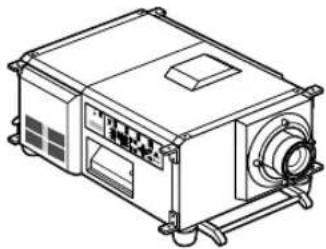
natural_image
Line drawing of a mechanical device with ports and a central fan (no text or symbols)□ Remote control (RD-371E)
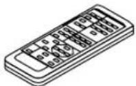
☐ UM-3 AA size battery (for the remote control) x 2

□ Remote cable (4 m) x 1
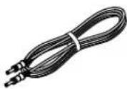
□ Remote cable (16 m) x 1

□Lens holder (NC-PH01)

□ Small iris x 1

□Wire stopper x 1

□Sheet of title labels (for 20 labels) x 2

□User's Manual (This document)

□ Power cord (grounded)
Connect this projector to the power outlet.
Three types of power cords are supplied with this projector: for Japan, for the U.S. and for European countries.
• Power cord for Europe(AC230V)
• Power cord for North America (
AC120V)
• Power cord for Japan ( AC100V)


TIP
- In the event that you did not receive all of the accessories outlined above, or some are damaged, contact your dealer/distributor.
Differs slightly from the drawings in this manual, but there is no problem in actual use.
1-3. Names of the Projector Parts
1-3-1. Front of the projector
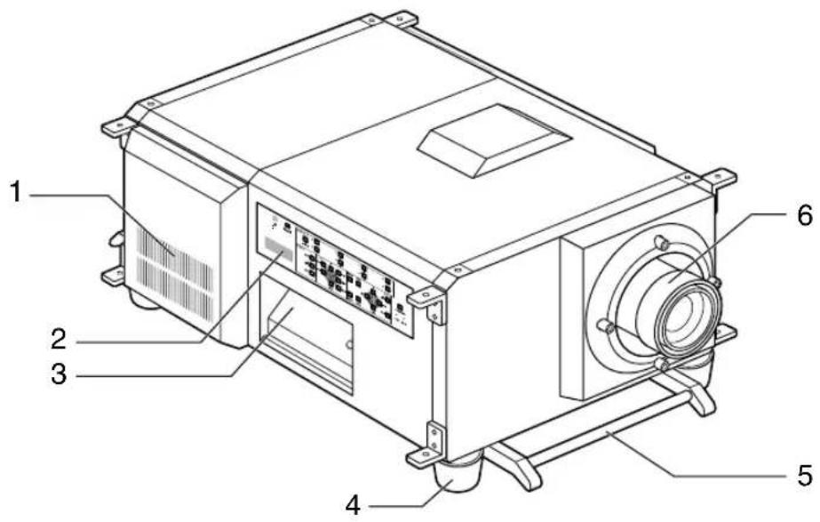
- Air inlet
Air is taken in here to provide cooling of the projector.
- Control panel
On the control panel, power to your projector is turned on or off, signals are selected, and various adjustments are made of projected screen. (See page 9)
- Connection terminals
Various image signal cables are to be connected here. (See page 7)
- Feet (in four positions on the bottom)
In the ordinary installation, you can adjust the projector inclination at 4 positions.
- Carrying handles
Hold the carrying handles when carrying your projector.
There are a total of two carrying handles, a set of bottom ones on the front and the back of your projector.
- Lens (optional)
Images are projected from the lens. Please contact your dealer/distributor to install or replace the lens.
NOTE
Do not cover the air inlet and outlet during operation. Inadequate air intake may lead to a rise in inside temperature, thus causing a fire or serious projector failure.
- What's in the Box? and the Names of the Projector Parts
1-3-2. Rear of the projector
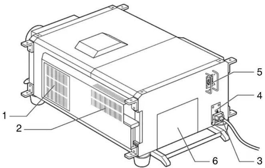
1. Air inlet
Air is taken in here to provide cooling of the projector.
2. Air outlet
The heat of the lamp is vented here.
3. Power cord
Connect the power cord to an AC outlet.
4. Function ground
The function ground is used when you wish to establish a common ground potential between the projector and the image-sending device or other equipment.
This is not a power supply ground terminal.
5. Main power switch
Connect the power cord to an AC outlet and set the main power switch to ON, then your projector will enter a standby state.
6. Lamp cover
The lamp house is accommodated. Mount and remove the lamps from here. For lamp mounting and removal, consult with your dealer.
NOTE
- Do not cover the air inlet and outlet during operation. Inadequate air intake may lead to a rise in inside temperature, thus causing a fire or serious projector failure.
- Do not touch the air outlet when your projector is operating. Otherwise, the high temperature may cause burns.
1-3-3. Connection terminals
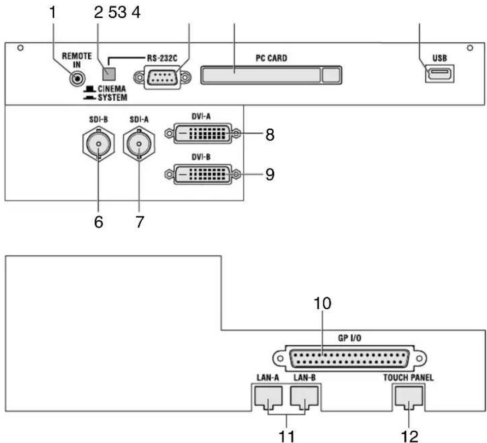
1. Remote control input terminal (REMOTE IN) (Stereo mini)
Connect the remote control of the projector, using the supplied remote control cable.
Memo
- The projector's remote control can be used by connecting with the remote control cable. (See page 13)
2. PC control signal switch (CINEMA/SYSTEM)
Use this to set data on the projector.
3. PC control terminal (RS-232C) (D-Sub 9P)
This is used when the service personnel sets the data for the projector or operates the projector from PC via RS-232C. Use a commercially available RS-232C straight cable to connect the projector to the PC.
4. PC card slot
- Set a wireless LAN card, and you can control the projector from a PC, using a wireless LAN Please inquire your dealer/distributor about a wireless LAN card that can be used.
- Use this slot when doing maintenance on your projector.
5. USB port (USB) (type A)
Use this port when doing maintenance on your projector.
6. HDSDI A input terminal (SDI-A) (BNC)
Connect a Video Server of Video source to this terminal. Use a 75Ω coaxial cable.
7. HDSDI B input terminal (SDI-B) (BNC)
Connect a Video Server or Video source to this terminal. Use a 75Ω coaxial cable.
8. DVI-D A input terminal (DVI-A) (DVI-D 24P)
Connect the DVI-D output terminal of a PC to this terminal. Use a commercially available DVI-D signal cable (Single Link).
-
What's in the Box? and the Names of the Projector Parts
-
DVI-D B input terminal (DVI-B) (DVI-D 24P)
Connect the DVI-D output terminal of a PC to this terminal. Use a commercially available DVI-D signal cable (Single Link).
- External control terminal (GP I/O) (D-Sub 37P)
Use this terminal when controlling your projector from an external switcher. (See page 48)
- Ethernet port (LAN-A, LAN-B) (RJ-45)
Use this port when controlling your projector in LAN connection from a PC. Use a commercially available LAN cable (10Base-T/100Base-T) to connect the projector to the PC.
- Ethernet port for the touch panel (TOUCH PANEL) (RJ-45)
This terminal is for future extensions.
1-3-4. Control panel
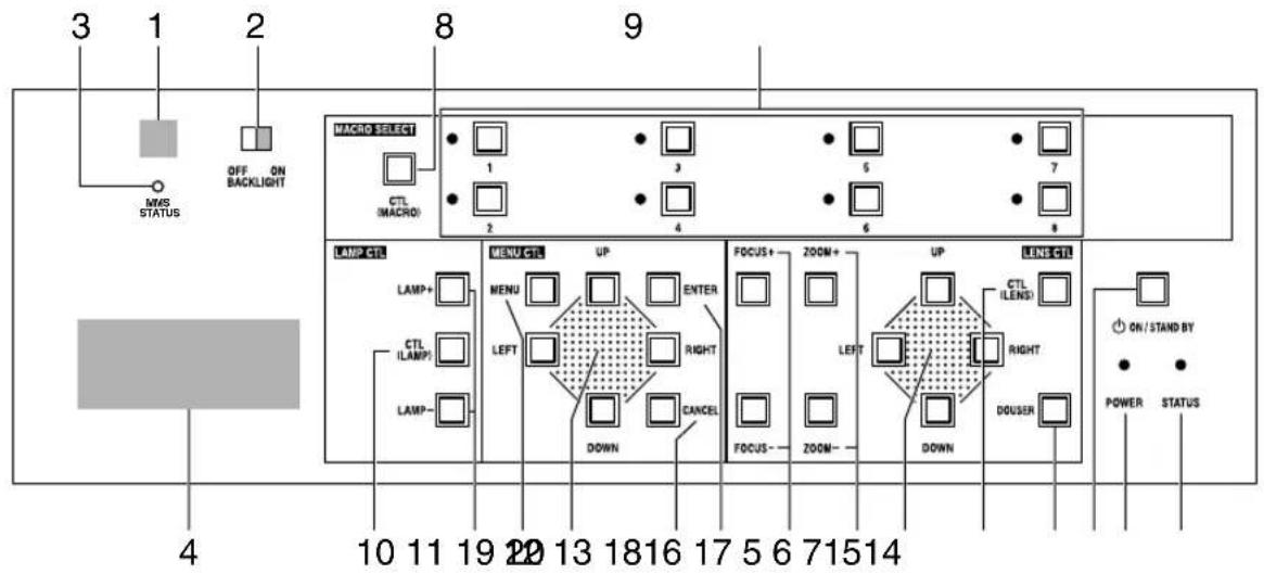
1. Remote control light reception unit
This receives signals from the remote control.
2. BACKLIGHT switch
Operate this switch to turn on/off the back light of the LCD screen and operation panel.
3. MMS STATUS indicator
This indicates the link status of the optional multi-media switcher (MMS).
| Off | When not using multi-media switcher. |
| Orange lighting | When linked to multi-media switcher. |
| Orange blinking | Preparing link with multimedia switcher. |
| Red blinking | When a link error occurs. |
4. LCD screen
The liquid crystal display screen shows menus and setting values for the operation of your projector.
5. POWER button
Press this button to turn on or off (standby) he power to your projector. Press this for more than three seconds.
When turning on the power to the projector, first set the main power switch to the main unit to ON, thereby setting the projector in a standby state. (See page 19)
6. POWER indicator
| Green lighting | When power is on. |
| Green blinking | When the douser is closed. |
| Orange lighting | When the power is off (in standby state). |
| Orange blinking | When the cooling fan(s) is running immediately after power-off. |
7. STATUS indicator
| Off | When the projector is operating normally. |
| Red blinking | When an error has occurred.An error code is displayed on the LCD screen. |
8. CTL (MACRO) button
Press the CTL (MACRO) button together with MACRO SELECT 1 to 8 buttons.
MACRO SELECT<1> to <8> button does not work individually.
1. What's in the Box? and the Names of the Projector Parts
9. 1 to 8 buttons
Press the 1 to 8 buttons while depressing the CTL (MACRO) button to select titles (input signals) assigned to each button. To this projector, 100 titles at most can be registered (input signal registration). Among the registered titles, any 8 titles can be assigned to the buttons <1> to <8>.
The indicator to the left of the buttons show the assigned/selected status of titles.
Request your dealer/distributor for details on registering and changing titles.
| Green lighting | When any title is assigned to the button. |
| Orange lighting | When title is selected. |
| Off | When any title is not assigned to the button. |
10. CTL (LAMP) button
Press the CTL (LAMP) button together with the LAMP +/- buttons.
11. LAMP +/- buttons
Press the LAMP +/- buttons while depressing the CTL (LAMP) button to adjust the output (brightness) of the lamp. (See page 23)
12. MENU button
Press this button, and menus for various settings and adjustments will be displayed. (See page 26)
13. [MENU CTL] UP/DOWN/LEFT/RIGHT buttons
Press the [MENU CTL] UP/DOWN/LEFT/RIGHT buttons when the menu is displayed to select menu items.
14. CANCEL button
Press the CANCEL button to return to previous menu item.
15. ENTER button
Press the ENTER button, and the displayed menu item is actioned.
16. FOCUS +/- buttons
Press the FOCUS +/- buttons while depressing the CTL (LENS) button to adjust the focus of the projected image. (See page 23)
17. ZOOM +/- buttons
Press these buttons while depressing the CTL (LENS) button, for fine adjustment of the size of projected image. (See page 23)
18. [LENS CTL] UP/DOWN/LEFT/RIGHT buttons
Press the [LENS CTL] UP/DOWN/LEFT/RIGHT buttons while depressing the CTL (LENS) button to move (lens shift) the position of the projected image up, down, left and right. (See page 22)
19. CTL (LENS) button
Press the CTL (LENS) button together with the FOCUS +/- button, the ZOOM +/- button, the [LENS CTL] UP/DOWN/LEFT/RIGHT button and the DOUSER button.
The FOCUS +/-, ZOOM +/- [LENS CTL] UP/DOWN/LEFT/RIGHT and DOUSER buttons do not function when pressed alone.
20. DOUSER button
Press the DOUSER button while depressing the CTL (LENS) button to open and close the douser.
1-4. Names on the Remote Control
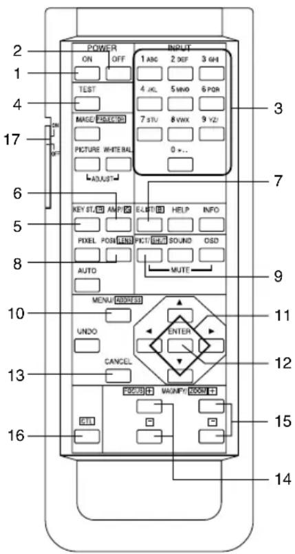
1. POWER ON button
Operate this button to turn on the power to your projector.
Press it three seconds or longer.
When turning on the power to your projector, first set the main power switch to the main unit to ON, which puts your projector on standby. (See page 19)
2. POWER OFF button
Operate this button to turn off (standby) the power to your projector. Press it three seconds or longer.
3. Numeric buttons (1 to 0 buttons)
Use these buttons to enter alphanumeric characters. (See page 28)
4. TEST button
- Press this button, and a test pattern will be displayed.
Check the test pattern on the LCD screen by pressing the SELECT ◀/▶ button, then press ENTER to set your selection.
To cancel the test pattern display, reselect the signal to project.
5. KEYSTONE / R button
Press the KEYSTONE(R) button while depressing the CTL button, then the red (R signal) of the test pattern will be turned off temporarily. Press this button again while depressing the CTL button, and the red (R signal) will be projected again.
6. AMPLITUDE / G button
Press the AMPLITUDE (G) button while depressing the CTL button, then the green (G signal) of the test pattern will be turned off temporarily.
Press this button again while depressing the CTL button, and the green (G signal) will be projected again.
7. ENTRYLIST / B button
Press the ENTRYLIST (B) button while depressing the CTL button, then the blue (B signal) of the test pattern will be turned off temporarily.
Press this button again while depressing the CTL button, and the blue (B signal) will be projected again.
8. POSI / LENS button
Press the POSI/LENS button while depressing the CTL button, to adjust the position of projected screen (Lens Shift Mode). (See page 22)
9. PICT / SHUT button
- Press this button to turn off image projection temporarily. Press it again, and the image will be projected again.
- Press the PICT / SHUT button while depressing the CTL button, then the douser sill operate to shut off the light for projection. The POWER indicator blinks in green while the douser is operating. Press this button again while depressing the CTL button to cancel the operation of the douser.
NOTE
When GPIO Control is set to "Enable", it is not possible to turn the power on/off and the douser function.
10. MENU button
Operate this button, and menus for various settings and adjustments will be displayed on the LCD screen. (See page 26)
1. What's in the Box? and the Names of the Projector Parts
11. SELECT ▼▲◀▶ buttons
- Press the SELECT ◀/▶ button when the menu is displayed, and a menu item can be selected.
- Press the SELECT ▼ button when the menu is displayed, and a submenu will be displayed.
- Press the SELECT ▲ button when the menu is displayed, and a menu one level above will be displayed.
- During character entry, press the SELECT ◀ button while depressing the CTL button, then one character will be deleted.
12. ENTER button
Press the ENTER button, and the displayed menu item is actioned.
13. CANCEL button
Press the CANCEL button to return to the previous menu item.
14. FOCUS +/- buttons
Press the FOCUS +/- button while depressing the CTL button, to make lens focus adjustment. (See page 23)
15. ZOOM +/- buttons
Press the ZOOM +/- button while depressing the CTL button, to make lens zoom adjustment. (See page 23)
16. CTL button
The CTL button is a shift function used to access alternative functions on other buttons.
17. Back light switch
When this is set to [ON], the characters on the remote controller will light up.
- When using the remote control with infrared ray signals
If the remote control device is not operated for 30 seconds after turning "ON" the back light switch, the back light switch will automatically extinguish itself. Thereafter, it will light again when the remote control buttons are operated. - When using the remote control connected to the remote control cable
The back light will constantly light when the power to the projector is turned on and when the projector is in standby status.
NOTE
- The following buttons cannot be used with this projector: WHITE BAL., ADJUST PICTURE, IMAGE, INFO., PIXEL., MUTE SOUND, MUTE OSD, HELP, AUTO, UNDO
Inserting the batteries
[1] Remove the battery case cover on the backside of the remote control.
[2] Insert the UM-3 size AA batteries into the case. Be careful of the direction poles on the batteries.
[3] Restore the cover.
NOTE
- When replacing the batteries, always purchase two of the same type of UM-3 size AA batteries.
Effective range of the remote control
To operate the remote control using infrared rays, and not using the remote control cable, point the remote control transmission unit toward the remote control reception unit on the projector. Signals from the remote control can generally be received within the range shown in the figure below.
![[Range of reception in the horizontal direction] Lens 30° 7m 30° Remote control Reception unit on projector (Top view of the projector)](/content/2026/05/1094082/images/9a8d9d65cbf64d781e389ae31841bd3aed63f717003426087bc0f8a9c0bf5e00.jpg)
(Note) The effective range depicted in the figure may differ slightly in actual use.
Using the remote control cable
Use the remote control cable when there are objects that interrupt or obstruct the space between the remote control reception unit on the projector and the remote control, or when you are using the remote control beyond its effective range. Note that the remote control cable is connected first to the remote control, then to the projector head.

Notes for use of the remote control
- Do not drop or handle the remote control in a careless manner.
- Do not allow the remote control to be splashed with water or any other liquid. If the remote control should get wet accidentally, wipe the liquid off immediately.
- Be sure to use the remote control in a place free from heat or dampness as far as is practicable.
- The remote cable is connected first to the remote control, then to the projector head. The leading end of the remote cable is the power supply unit, so be careful not to touch the other end of the remote cable to the projector head or other devices while only the remote cable is connected to the projector.
2. Installation and Connection
2-1. Steps for setting up and connecting
Use the following steps for setting up your projector:
- Step 1
Setup the screen and projector. (Contact your dealer to carry out the setup.)
- Step 2
Connect cables to the image input terminals. (See page 15)
Connect cables to the various control terminals. (See page 16)
- Step 3
Connect the power cord. (See page 17)
2-2. Connecting the image input terminals
Your projector has four image input terminals, namely, the HDSDI A input terminal, the HDSDI B input terminal, the DVI-D A input terminal, and the DVI-D B input terminal.
- HDSDI A/B input terminal (SDI A/SDI B).... Inputs serial digital images from a Video Server or Video source.
- DVI-D A/B input terminal (DVI A/DVI B).... Inputs digital RGB signals from a PC.

flowchart
graph TD
    A["75Ω coaxial cable"] --> B["PC CARD"]
    C["DVI-D signal cable"] --> B
    B --> D["USB"]
    B --> E["Computer"]
    B --> F["Remote IN"]
    B --> G["CINEMA SYSTEM"]
    B --> H["SDI-B"]
    B --> I["SDI-A"]
    B --> J["DVI-A"]
    B --> K["DVI-B"]
2-3. Connecting the various control terminal
For control, your projector comes with such ports as the PC control terminal and the Ethernet port (RJ-45).
- PC control terminal (PC CONTROL) .... Use this terminal when controlling the projector in serial connection from a PC.
- Ethernet port (LAN 1/LAN 2) .... Use this port when controlling the projector in LAN connection from a PC.

flowchart
graph TD
    A["RS-232C"] --> B["PC CARD"]
    B --> C["CINEMA SYSTEM"]
    C --> D["SDI-B"]
    C --> E["SDI-A"]
    C --> F["DVI-A"]
    C --> G["DVI-B"]
    B --> H["USB"]
    I["Ethernet cable"] --> J["GP I/O"]
    J --> K["LAN-A"]
    J --> L["LAN-B"]
    J --> M["TOUCH PANEL"]
2-4. Connecting the power cord
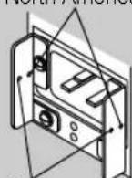
After making certain that the main power switch of your projector is OFF, connect the power cord to 100-120VAC or 200-240VAC three-prong outlet (grounded).
CAUTION

- Please contact your dealer/distributor to perform the wiring for connection of the power cord to your projector.
- Be sure to ground the equipment to ensure safety. To avoid electric shocks, request a professional to carry out the grounding. Be sure to perform earth connection before inserting the power plug into the wall outlet.

NOTE
- In the following instances, do not disconnect the power plug from the outlet. Otherwise, trouble may occur:
- When the fan is running after the power is turned off.
- When using a Flash Memory card or LAN card, the card may be damaged.
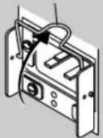
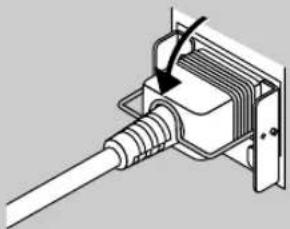
• Using the Power Cord Stopper
The Power cord wire stopper is provided on the projector so that the cord cannot be accidentally unplugged from the AC IN.
-
Lift up the wire stopper. 2. Plug the power cord into the AC IN.
-
Lift down the wire stopper to hold the power cord.
Wire stopper

natural_image
Diagram of a cable inserted into a transformer core, showing internal wiring and mounting bracket (no text or symbols)For North America
For Europe
3.
Projection of Images (Basic Operation)
3-1. Steps of projecting images
- Step 1
Turn on the power to the projector. (See page 19)
- Step 2
Select the title of input signal. (See page 21)
- Step 3
Adjust the position and size of the projected screen. (See page 22)
- Step 4
Turn off the power to the projector. (See page 24)
3-2. Turning your projector on
Preparation: Supply AC power to the projector head.
Please contact your dealer/distributor to connect the power cord.
NOTE
- Turn off the main power switch to the projector head when supplying or cutting AC power to the projector. If power is supplied or cut while the main power switch is turned on, the projector will be damaged.
- Be sure to turn your projector on or off in two steps of operation with the "main power switch" and the "POWER button" ("POWER ON/OFF button" on the remote control).
- Turning power on (See this page)
[1] Turn the "main power switch" on the projector head to on. Your projector is set in a standby state.
[2] Press the POWER button (POWER ON button on the remote control) three seconds or longer. Your projector is turn on. - Turning power off (See page 24)
[1] Press the POWER button (POWER OFF button on the remote control) three seconds or longer. Your projector is set in a standby state.
[2] When the fan has stopped running, set the "main power switch" on the projector head to OFF. Your projector is turned off.
1 Remove the lens cap.
2 Turn the main power switch on the side of your projector head to on.
The POWER indicator lights up orange (standby state).

3. Projection of Images (Basic Operation)
3 Press the POWER button on the control panel of your projector three seconds or longer.
Your projector is turn on, and the screen glows light about 30 seconds later. The POWER indicator of the projector lights up green.
- When controlling with the remote control, press the POWER ON button three seconds or longer.

NOTE
- While your projector is on, be sure to have the lens cap removed from the lens. Otherwise, the lens cap may get deformed due to a heat buildup.
- In the following instances, the power to your projector cannot be turned on even if you press the POWER button.
- When the inside temperature is abnormally high. The protective function prevents power from turning on. Wait some time (until the projector inside cools down) and then turn on the power.
- When the STATUS indicator is blinking without the lamp lighting up after power-on. Your projector may be in trouble. Check the error display on the LCD screen and contact your dealer/distributor for instructions.
- Note that the image may sometimes flicker until the lamp has stabilized (5 to 10 minutes) after power-on. This is due to the characteristics of the lamp and is not trouble of your projector.
3-3. Selecting the title of input signal
This projector allows you to select pre-registered signals using the signal selection buttons on the control panel (up to 8 signals). Request your dealer/distributor for details on registering and changing titles. This section explains the steps for selecting registered signals.
1 Turn on the power to the image devices connected to the projector.
2 Press the MENU button.
3 Press the [MENU CTL] LEFT/RIGHT button to display "Title Select" on the LCD screen.
At each press of the [MENU CTL] LEFT/RIGHT buttons, the display will cycle as "Title Select" "Configuration" "(Title Setup)" "Information."

4 Press the [MENU CTL] DOWN button.
The title of the input signal is displayed.
- When you have made a wrong selection, press the [MENU CTL] UP button. A return will be made to the previous menu.

5 Press the [MENU CTL] LEFT/RIGHT buttons to display "Title of Signal to be Projected" on the LCD screen.
6 Press the ENTER button.
The title of the signal to be projected is selected.
- The (*) mark on the LCD indicates that this is the currently selected item.

3-4. Adjusting the position and the size of projected screen
3-4-1. Displaying the test pattern
1 Press the TEST button on the remote control. Alternatively, select the test pattern from the signal selection button.
If you register the test patterns to the signal selection buttons (<1> to <8> buttons), select the test pattern according to "3-3. Selecting the title of input signal (See page 21)".
The mode for selecting the test pattern is set.

2 Press the SELECT ◀/▶ button.
The display of the test pattern name on the LCD switches.

3 Display on the LCD the name of the test pattern to be projected, then press the ENTER button.
The test pattern is displayed.
- To cancel the test pattern display, reselect the signal to be project.

3-4-2. Adjusting the position of the projected screen (Lens shift)
1 Press the [LENS CTL] UP/DOWN/LEFT/RIGHT buttons while depressing the CTL button, on the control panel of your projector as required.
The position of the projected screen will move upward, downward, left or right.
- When controlling with the remote control, press the POSI/LENS button while depressing the CTL (LENS) button.

3-4-3. Fine adjustment of the size of the projected screen (Zoom)
1 Press the ZOOM +/- buttons while depressing the CTL (LENS) button on the control panel of your projector as required.
- When controlling with the remote control, press the ZOOM +/- button while depressing the CTL (LENS) button.

3-4-4. Focusing the projected screen (Focus)
1 Press the FOCUS +/- buttons while depressing the CTL (LENS) button, on the control panel of your projector as required.
- When controlling with the remote control, press the FOCUS +/- button while depressing the CTL (LENS) button.

3-4-5. Adjusting the brightness of the projected screen (Lamp output)
1 Press the LAMP +/- buttons while depressing the CTL (LAMP) button, on the control panel of your projector as required.

3-5. Turning your projector off
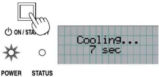
1 Press the POWER button on the projector control panel for three seconds or longer.
The power to the projector is turned off. The POWER indicator will blink in orange (cooling state).
The fan will continue to rotate while cooling, and the amount of time remaining for cooling is displayed on the LCD screen. The cooling-off time is 3 minutes.
When cooling has ended, the POWER indicator lights in orange (Standby).
- When controlling with the remote control, press the POWER OFF button for three seconds or longer.
2 When the projector has entered the standby state, turn the main power switch on the projector head to off.
The projector POWER indicator will extinguish and the main power will turn off.
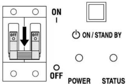
3 Turn off the AC power to the projector head.
NOTE
- In the following instances, do not turn off the main power switch or disconnect the AC power. Doing so can damage the projector.
• While projecting images
- While the fan is running after the power is turned off (The cooling-off time is 3 minutes)
4.
Using Menus
4-1. Basic operation with adjustment menus
To adjust the projector, display the menu on the LCD screen of the projector control panel.
4-1-1. Screen display
The menu display screen is composed of a menu display field (the upper two lines) and a setting item display field (the bottom two lines).

← Displays the main menu or submenus.
← Displays submenus or selection items.
← Displays settings and selection status.
← Displays settings, selected items and information on selected menus.
The meanings of symbols in the menu display screen are outlined below.
 | Indicates that there is a menu of a higher level.Press the [MENU CTL] UP button to return to a menu one level above. |
 | Indicates that there is a selected item or menu at the same level.Press the [MENU CTL] LEFT/RIGHT button to display other selected items or menus. |
 | Indicates that there is a menu of a lower level.Press the [MENU CTL] DOWN button to display the menu one level below. |
 | Indicates that there are setting items of a lower level.Press the [MENU CTL] UP button to return to a menu one level above.Press the [MENU CTL] DOWN button to display the setting item one level below. |
4. Using Menus
When not displaying menus, the following screen is normally displayed.
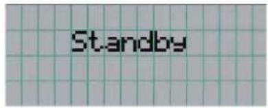
When in standby
When the projector is in a standby state (the main power switch in on), the following is displayed.
When power is turned on
When the power is turned on, the following is displayed.
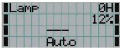
← Displays the hours of lamp bulb use.
← Displays the lamp output (%).
← Displays the selected title.
← Displays the selected port.
When the power is turned off
The amount of time remaining for cooling is displayed as shown below, when the power to the projector head is turned off.

4-1-2. Operating menus
Preparation: Turn your projector on. (See page 19)
1 Press the MENU button on the control panel of your projector.
The menu is displayed in the LCD screen.

2 Press the [MENU CTL] LEFT/RIGHT buttons to display "Information."
At each press of the [MENU CTL] LEFT/RIGHT buttons, the display yp I cycle as "Title Select" "Configuration" "(Title Setup)" "Information."
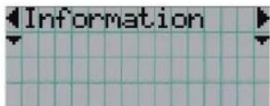
3 Press the [MENU CTL] DOWN button.
The submenu "Lamp" of "Information" is displayed.
The menu item can be selected by pressing the ENTER button instead of the SELECT DOWN button. To return to the previous state, press the [MENU CTL] UP button, or the CANCEL button.

4 Press the [MENU CTL] LEFT/RIGHT button to select the submenu "Version."
At each press of the [MENU CTL] LEFT/RIGHT button, the display will cycle as "Lamp" "Macro Key" "Usage" "Error Code" "Version" "IP Address" "MMS Status."

5 Press the [MENU CTL] DOWN button.
The submenu "BIOS" another rank lower than "System" is displayed.

6 Press the [MENU CTL] LEFT/RIGHT button to select the submenu "Data."
At each press of the [MENU CTL] LEFT/RIGHT button, the display will cycle as "BIOS" "Firmware" "Data" "Serial No.," and each version information is displayed.
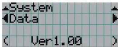
7 Press the [MENU CTL] UP button several times.
At each press of the [MENU CTL] UP button, the display will return to a menu one level above.
4-1-3. How to enter alphanumeric characters
Alphanumeric characters are entered for items, such as the title of input signal.
With this projector, the characters are inputted by pressing numeric buttons on the remote control.

By pressing the numeric buttons, the characters can be inputted as shown in the table below.
- To delete a character during entry, press the SELECT ◀ button while depressing the CTL button.
[Example of Entry]
To enter "XGA" for example, use the following procedure:
(1) Press the 8 button three times.
- To input characters using the remote control, only numbers can be entered with [password] and the security [keyword].
4-2. Table of adjustment menus
Menus in parentheses are menus for our service personnel. Normally, these menus cannot be used.
| Main menu | Submenu | Description | Reference page | |
| Title Select | "Title Memory Name" | Selects the title of the signal to be projected. | 30 | |
| TEST Pattern | Selects the test pattern to be projected. | 30 | ||
| Configuration | Lamp Setup | Adjust | Adjusts lamp brightness. | 31 |
| Feedback | Sets the lamp brightness constant mode that uses a brightness sensor. | 31 | ||
| (Setup) | Douser Mode | Selects whether to use the douser (screen mute) when switching signals. | - | |
| Ext. MMS Link | Sets whether to connect the multi-media switcher (MMS). | - | ||
| Panel Key Lock | Locks the buttons on the projector's control panel so that they cannot be operated. | - | ||
| GPIO Port | Selects the target of GPIO port control. | - | ||
| FactoryDefault | Returns the settings to their default values (only macro keys and titles, or all settings). | - | ||
| (Installation) | Image Orient | Selects the projection method (desktop front / desktop rear / ceiling front / ceiling rear). | - | |
| Lens Center | Moves the lens shift position to the center. | - | ||
| MMS Select | Selects the multi-media switcher (MMS) to connect. | - | ||
| Baudrate | Sets the PC control connector (RS-232C) data transmission speed (bps). | - | ||
| Date/Time | Sets the date and time on the projector. | - | ||
| Bulb Alignment | Sets the lamp bulb alignment. | - | ||
| (Memory) | Lamp | Saves the current lamp setting. | - | |
| Lens | Saves the current lens setting. | - | ||
| (Title Setup) | Macro Key | Macro Key No.1-8 | Sets the titles to be assigned to the macro keys of 1 to 8. | 31 |
| Information | Lamp | Output | Displays the lamp output setting. | 32 |
| Macro Key | Macro Key No.1-8 | Displays the titles assigned to the macro keys of 1 to 8. | 32 | |
| Usage | Displays the usage times of the projector, lamp bulb, lamp house and bulb warning. | 32 | ||
| Error Code | Displays the currently occurring error. | 32 | ||
| Version | Displays the version of the projector head. (BIOS, Firmware, Data, and Serial No.) | 33 | ||
| IP Address | System | Displays the SYSTEM IP address. | 33 | |
| Cinema | Displays the CINEMA IP address. | 33 | ||
| MMS Status | Displays the link-status of the connected multi-media switcher (MMS). | 33 | ||
4-3. Title Select
4-3-1. Title select (Title Memory)
Selects the title of the signal to be projected.
You can register up to 100 titles. You can also assign registered titles to the Macro keys of 1 to 8 on the projector's control panel and call them up directly using those buttons.
Request your dealer/distributor for details on registering and changing titles.

← Displays the currently selected item with asterisk (*).
← Selects the title to be projected.
4-3-2. Test Pattern
Selects the test pattern to be projected.
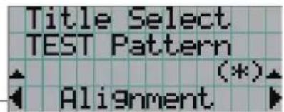
← Displays the currently selected item with asterisk (*).
← Selects the test pattern to be projected.
OFF, Alignment, Cross Hatch, Convergence, Red, Green, Blue, White, Black, White 50% [IRE], H-Ramp, Logo
4-4. Configuration
Please request your dealer/distributor to perform the settings.
4-4-1. Lamp Setup
Adjust
Adjusts the lamp output (brightness). Control the output at 30 to 34 W increments.
![Lamp Setup Adjust 85 [%] (*) 128.0 [A]](/content/2026/05/1094082/images/5c055a25ab2e9ddd28b0fdc8cb3e87fce3b26e352f4186111ff7209607bfbada.jpg)
← Displays the lamp output (%) with regard to the setting.
← Adjusts the lamp brightness.
Feedback
Sets the lamp brightness constant mode that uses a brightness sensor.

← Displays the currently selected item with asterisk (*).
← Displays the setting.
| Disable | Disables the lamp brightness constant mode. |
| Enable | Enables the lamp brightness constant mode. |
4-5. Title Setup
Sets the titles to be assigned to the macro keys.
Request your dealer/distributor to perform the settings.
4-6. Information
Displays the hours of lamp bulb use, the version information and error codes.
4-6-1. Lamp
Displays information relating to the lamp. (Such as lamp output and the utilization time of lamp bulb.)
Output
Displays the lamp brightness (output) setting.
![Lamp Output < 1050 [W]](/content/2026/05/1094082/images/c6f63e028ec24251824295db3e866c6a8c8d03017a23356347646ea53ec1b11f.jpg)
← Displays the power consumption (W).
4-6-2. Macro Key
Displays the titles assigned to the macro keys of 1 to 8 on the projector's control panel.

← Selects the macro key number whose contents you want to display.
← Displays the registered names of the assigned titles.
4-6-3. Usage
Projector and lamp bulb utilization times and the remaining usable time for the lamp bulb are displayed.
![Usage Projector ( 0 [H] )](/content/2026/05/1094082/images/117fe2f4bf0b7f846d67f64f876371bf6cb8fee602fa9602d630dd2ae78c22f0.jpg)
← Selects the item to display.
← Displays the hours of use (H).
| Projector | Displays the hours of projector head use. |
| Bulb | Displays the utilization time of the currently used lamp bulb (Lamp utilization time). |
| Remainig Time | Displays the remaining usable time for the lamp bulb. |
4-6-4. Error Code
Displays the error code when an error occurs. See the "Error Code List" in the Appendix for details on error codes.
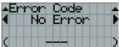
← Displays the code of the error currently occurring.
← Displays the name of the error currently occurring.
When multiple errors occur, you can display them by pressing the [MENU CTL] LEFT/RIGHT buttons.
4-6-5. Version
Displays the versions of the projector head.
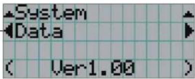
← Selects the item to display.
← Displays the version information.
| BIOS | Displays the BIOS version of the projector head. |
| Firmware | Displays the firmware version of the projector head. |
| Data | Displays the data version of the projector head. |
| Serial No. | Displays the serial number of the projector head. |
4-6-6. IP Address
Displays the IP address set in the projector head.
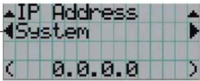
← Selects the item to display the IP address.
← Displays the IP address.
| System | Displays the IP address set for the projector head (System). |
| Cinema | Displays the IP address set for the projector head (Cinema). |
4-6-7. MMS Status
Indicates the link-status of the multi-media switcher (MMS) connected to your projector.

← Displays the status information of MMS linked operations.
← Displays the IP address.
| External | External multi-media switcher (MMS) is linked. |
| Not Use | There is no link established. |
5.
Maintenance of Your Projector
NOTE
Please request your dealer to perform lamp replacement, filter replacement and cleaning of the projector inside.
5-1. Cleaning the Cabinet
Be sure to always check that the AC power supply of the projector head is disconnected before carrying out maintenance of your projector.
- Wipe with a dry, soft cloth without nap.
When the cabinet is excessively dirty, wipe with cloth well wrung after being dampened with a neutral detergent diluted with water and then finish up with a dry cloth.
When you use a chemical dust cloth, follow the instructions in the manual attached to it.
- Do not use a solvent, such as thinner or benzene. The coating may deteriorate or peel off.
- When removing dust on the ventilation opening, suck it off using an adapter with a brush on a vacuum cleaner. Never allow the cleaner without an adapter to come into direct contact or use a nozzles adapter in cleaning.
- Clean the ventilation opening at regular intervals. Dust, if allowed to accumulate there, may cause heating inside, which leads to functional trouble. The interval, which can vary with the location of your projector, is about 100 hours.
- Do not damage the cabinet by scratching it or allowing hard objects to hit it. This can scratch the projector.
- Consult your dealer/distributor about cleaning the inside of the projector.
NOTE
Do not allow insecticide or other volatile liquid to splash on the cabinet, lens or screen. Also, do not allow any rubber or plastic object to remain in contact with the cabinet for a long time. The coating may deteriorate or peel off.
5-2. Cleaning the Lens
Clean the lens the same way as with camera lens (using a commercially available camera blower or cleaning paper for glasses). Take care not to damage the lens when cleaning.
6.
Appendix
6-1. Troubleshooting
Before asking for repair, please check your connection, settings and operation once again. If the trouble cannot be corrected, please contact your dealer/distributor for instructions or repair.
6-1-1. Problems and where to check
| Problem | Check these items |
| The projector cannot be turned on. | Check to see if the power plug is properly connected to the outlet. |
| Make certain that the main power switch is ON. | |
| Check to see whether the panel key lock function is activated. If so, the main unit's control buttons are locked and do not work, but the projector can be controlled using the remote control unit. | |
| Is the temperature inside the projector too high? When the inside temperature is too high, the protective function does not allow your projector to be turned on. Wait some time and then turn it on. | |
| The image cannot be projected. | Check to see if the connected input has been selected. |
| Check to see if a cable is properly connected to the input terminal. | |
| Check to see whether the douser is closed. | |
| Check to see if the settings are all adjusted properly. | |
| The image is distorted. | Check to see if the protractor is properly set up. |
| The image is blurred. | Make certain that the lens is properly focused. |
| Check to see if the screen and a projector are installed at correct angles. | |
| The projection distance may be larger than the focusing range. | |
| See if the lens and other parts have condensation on them. If the projector is turned on in a warm place after storage in a cold place, the lens and other optical components inside may develop condensation. In such a case, please wait several minutes until the condensation disappears. | |
| Video image is disturbed | Check whether the signal cable connected to the projector is disconnected. |
6. Appendix
| Problem | Check these items |
| The projector cannot be operated with the remote control. | Make sure the remote control transmission unit is facing the light reception unit on the projector. |
| Check whether the batteries are still good. Replace with new batteries. | |
| Check whether there is any obstructing object between the remote control and the light reception unit on the projector. | |
| Check whether you are outside of the remote control's effective range (7m). | |
| Check whether the remote control cable has become disconnected, if you are using the remote control by connecting with the remote control cable. | |
| The STATUS indicator blinks in red. | Your projector may have trouble. Please contact your dealer/distributor for instructions. |
| An error code is displayed. | See the "Error Code List" (page 38). |
6-2. Indicator display list
See the descriptions below when the blinking or lighting of the two indicators on the projector's control panel is observed.

6-2-1. POWER indicator
| Indicator condition | Projector condition | Note | |
| Off | The main power is off. | - | |
| Blinking light | Green | The projector is getting ready to turn on.The douser is closed. | Wait for a moment. |
| Orange | The projector is cooling down. | Wait for a moment. | |
| Steady light | Green | The projector is turned on. | - |
| Orange | The projector is in standby. | - | |
6-2-2. STATUS indicator
| Indicator condition | Projector condition | Note | |
| Off | Normal. | - | |
| Blinking light | Red | When an error has occurred. | An error message is displayed in the LCD screen.Check the content of the error. |
6-2-3. MMS STATUS indicator
| Indicator condition | Projector condition | Note | |
| Off | Multi-media switcher (MMS) not in use. | - | |
| Blinking light | Red | Link error | Link error. An error message is displayed in the LCD screen.Check the content of the error. |
| Orange | Preparing link with Multi-media switcher (MMS). | Wait for a moment | |
| Steady light | Orange | Multi-media switcher (MMS) is linked. | - |
6-3. Error code list
Please inquire your dealer/distributor about action to be taken for each error code.
Description is omitted for error codes 20 to 92.
| Error code | Error message | Description |
| 1 | Lamp Cover Open | Lamp cover is open. |
| 2 | Over Temp Lamp | Temperature (lamp temperature) is abnormal. |
| 3 | Fan Stop | DC fan stop. |
| 4 | GPSU Fail | Power supply is abnormal. |
| 5 | Lamp Unlit | Lamp doesn't light up. |
| 8 | Over Temp. LPSU | Temperature (in lamp power supply) is abnormal. |
| 9 | Over Temp. In | Temperature (inside of projector) is abnormal. |
| 10 | DLP PGOOD Fail | Engine power is abnormal. |
| 11 | DLP Comm. Fail | Cinema engine communication error. |
| 12 | E2PROM R Fail | E2PROM data read error is detected. |
| 15 | E2PROM W Fail | E2PROM data write error is detected. |
| 16 | Fan Stop Lamp | Stop of lamp cooling fan. |
| 17 | Pump Stop | Stopped for pump error. |
| 18 | Over Temp. DMD | DMD temperature error alarm. |
| 19 | E2PROM D Fail | E2PROM data failure. |
| 20 | System Fail | - |
| 21 | Self Test Fail | - |
| 22 | ARM Fail | - |
| 23 | DSP Fail | - |
| 24 | Interface FPGA Fail | - |
| 25 | Processor FPGA Fail | - |
| 30 | IB Diag Not Performed | - |
| 31 | IB FPGA Code Invalid | - |
| 32 | IB FPGA INITZ Fail | - |
| 33 | IB FPGA No-Load Set | - |
| 34 | IB FPGA DONE Fail | - |
| 35 | IB FPGA Reg R/W Fail | - |
| 36 | IB Framestore Test Fail | - |
| 37 | IB ANC FIFO Test Fail | - |
| 38 | IB RTC Serial # Fail | - |
| 39 | IB UART0 Fail | - |
| 40 | IB UART1 Fail | - |
| 41 | IB IIC Fail | - |
| 42 | IB Ethernet Fail | - |
| 43 | IB Sync-Serial Fail | - |
| 44 | IB File System Fail | - |
| 45 | IB Formatter Fail | - |
| 46 | IB Flash Protect Fail | - |
| 47 | IB GPI Macro Fail | - |
| 48 | IB A/D Macro Fail | - |
| 60 | PB Diag Not Performed | - |
| 61 | PB FPGA Code Invalid | - |
| 62 | PB FPGA INITZ Fail | - |
| Error code | Error message | Desciption |
| 63 | PB McBSP XRDY Fail | - |
| 64 | PB FPGA Done Fail | - |
| 65 | PB FPGA Reg R/W Fail | - |
| 66 | PB Serial-ID Chip Fail | - |
| 67 | PB CLUT-SRAM Fail | - |
| 68 | PB OvFS-SDRAM Fail | - |
| 69 | PB Resizer FIR Fail | - |
| 70 | PB Resizer FIFO Fail | - |
| 71 | PB Other Fail | - |
| 90 | FB Red RDRAM Signature Fail | - |
| 91 | FB Green RDRAM Signature Fail | - |
| 92 | FB Blue RDRAM Signature Fail | - |
| 120 | DLP Ack Fail | Cinema block communication ACK error. |
| 123 | OverTime Bulb | Lamp bulb cumulative time is over. |
| 130 | MMS Comm. Fail | Multimedia switcher (MMS) link operation failure. |
6-4. Operation using an HTTP browser
6-4-1. Overview
The use of HTTP server functions will allow control of the projector from a web browser. Please be sure to use "Microsoft Internet Explorer 4.x" or a higher version for the web browser.
This device uses "JavaScript" and "Cookies" and the browser should be set to accept these functions. The setting method will vary depending on the version of the browser. Please refer to the help files and the other information provided in your software.
NOTE
The display's or button's response can be slowed down or operation may not be accepted depending on the settings of your network. Should this happen, consult your network administrator. The projector may not respond if its buttons are repeatedly pressed in rapid intervals. Should this happen, wait a moment and repeat. If you still cannot get any response, pull out and then reinsert the LAN card on the projector. Access is gained to the HTTP server functions by and specifying http://
6-4-2. Preparation before use
Make network connections and set up the projector and confirm that it is complete before engaging in browser operations. Operations with a browser that uses a proxy server may not be possible depending on the type of proxy server and the setting method. Although the type of proxy server will be a factor, it is possible that items that have actually been set will not be displayed depending on the effectiveness of the cache, and the contents set from a browser not be reflected in operation. It is recommended that a proxy server not be used unless it is unavoidable.
6-4-3. Handling of the address for operation via a browser
Regarding the actual address that is entered for the address or entered to the URL column when operation of the projector is via a browser, the host name can be used as it is with the host name corresponding to the IP address of the projector has been registered in the domain name server by a network administrator, or the host name corresponding to the IP address of the projector has been set in the "HOSTS" file of the computer being used.
(Example 1) When the host name of the projector has been set to "pj.nec.co.jp"
http://pj.nec.co.jp/index.html is specified for the address or the entry column of the URL to access HTTP server functions.
(Example 2) When the IP address of the projector is "192.168.10.10"
http://192.168.10.10/index.html is specified for the address or the entry column of the URL to access HTTP server functions.
6-4-4. Structure of the HTTP server
![Title List No. Port Screen Type Title 1 202A HDTV SCL A 2 202B HDTV SCL B 3 DVLA PC DVLA 4 DVLB PC DVLB 5 202A HDTV SCL A W-ANAMO 6 Test Pattern TEST Amount 7 Test Pattern TEST White100 8 Test Pattern TEST White50 Projector Status Default Port 202-A Free State Lamp Stage 0 [H] Lamp Power 52% Copyright ©RSC Xieotechnology, Utd 1000 - 2005](/content/2026/05/1094082/images/36e4c6ea6b86988e92cbd59c2ba429ecb59041871e364e8b41e3ce765b843453.jpg)
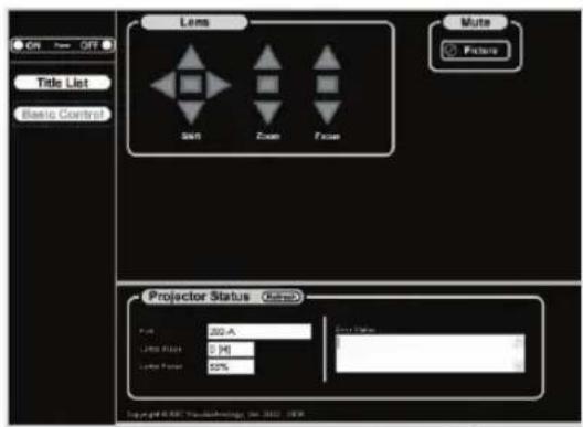
| Power | Controls the power to your projector.• On: Turns the power on.• Off: Turns the power off. | |
| Title List | Displays titles set in the projector (such as input port, screen type, and title).Check, and the title will be changed. | |
| Basic Control | Displays the basic control items. | |
| Lens | Controls the lens operation. | |
| Shift | ▲: Shifts the projected screen upward.▼: Shifts the projected screen downward.◀: Shifts the projected screen leftward.▶: Shifts the projected screen rightward.■: Stops the shifting.Shifting can also be stopped by clicking the same button one more time. | |
| Zoom | ▲: Zooms up the lens.▼: Zooms down the lens.■: Stops the zooming.Zooming the can also be stopped by clicking the same button one more time. | |
| Focus | ▲: Focuses up the lens.▼: Focuses down the lens.■: Stops the focusing.Focusing can also be stopped by clicking the same button one more time. | |
| Mute | Picture | Click and the douser closes and the projected picture disappears. Click once again and the picture will be projected again. |
| Projector Status | Displays the condition of the projector.• Port: Displays the input port of the selected title.Lamp Usage: Displays the hours of lamp use.Lamp Power: Displays lamp output (%).Error Status: Displays the status of errors occurring within the projector.Refresh: Updates the display of the following conditions. | |
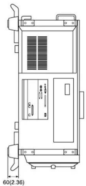
6-5. Outline Drawing
natural_image
Technical line drawing of an electrical cabinet or enclosure with ventilation grilles and control panels (no text or symbols)
Units: mm (inch)
6-6. Specifications
| Model No. | NC800C |
| Projection method | 3 chip DMD reflector method (DLP® method) |
| Panel resolution | 2048 x 1080 |
| Lamp type | 1.25 kW xenon lamp |
| Screen sizes | 8 m (Width) (Depends on setup conditions) |
| Contrast ratio | 200:1 or above |
| Lens adjustment function | Motorized lens shift (vertical/horizontal), motorized zoom, motorized focus, douser |
| Signal input terminal | RGB DIGITAL (2) DVI-D 24pin (TMDS specification)SDI (2) BNC (SMPTE 292M) |
| External Control | RS232C (1) D-sub 9 pinRemote controlLAN port (RJ-45) x 2USB port (type A)GPIO port (D-sub 37 pin)PC card slot (1) PCMCIA type II, card busLAN port for the Touch Panel (Note) |
| Power supply voltage | AC100 to 120V 50/60Hz,AC200 to 240V 50/60Hz |
| Input current | 12A (100 - 120V), 8.5A (200 - 240V) |
| Power consumption | 1.2kW to 1.44kW (100 - 120V), 1.7kW (200 - 240V) |
| Cooling method | Cooling air system (includes dust filter) |
| Noise level | Less than 45dB (When set to minimum brightness mode) |
| Installation | Orientation: Desktop/front, Desktop/rear, Ceiling/front, Ceiling/rear |
| Dimensions | 670mm(W) x 826mm(D) x 423mm(H) (Does not include protruding portions Includes foot) |
| Net weight | 66 kg (Excluding lens) |
| Environment | Operating temperature: 5 to 35°COperating humidity: 10 to 85% (non-condensing)Storage temperature: -10 to 50°CStorage humidity: 10 to 85% (non-condensing) |
| Regulations |
(Note) This is the terminal for future expansions.
* Note that these specifications and design can change without prior notice.
6-7. Pin Assignment and Functions of Terminal
6-7-1. PC CONTROL connector (D-Sub 9 pin)
This is an RS-232C interface for controlling the projector head from a PC. The projector operates as a DCE (Data Communication Equipment), so use a straight cable when connecting to a PC.
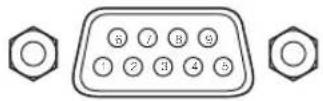
| Pin No. | RS-232C Signal Name | Functions as RS-232C | Projector Connector Operation |
| 1 | CD | Carrier detection | Not used (N.C.) |
| 2 | RXD | Reception data | Data transmission to an external device |
| 3 | TXD | Transmission data | Data reception from an external device |
| 4 | DTR | Data Terminal ready (Note 1) | Connection to 6 pins |
| 5 | GND | Signal GND | Signal GND |
| 6 | DSR | Data set ready (Note 1) | Connection to 4 pins |
| 7 | RTS | Transmission request | SYSTEM (Note 2): Hi-Z (Not used)CINEMA (Note 2): Hi-Z (Used) |
| 8 | CTS | Transmission available | SYSTEM (Note 2): Fixed at -6.5 V (Not used)CINEMA (Note 2): ± 10.5 V (Used: Depends on communication status) |
| 9 | RI | Ring indicator | Not used (N.C.) |
Note 1: Do not use DTR and DSR signals when communicating.
Note 2: Connector operations vary according to the PC control signal switch
(CINEMA/SYSTEM). (When in SYSTEM, do not use RTS and CTS signals.)
Internal Configuration Diagram of RS-232C Communication System
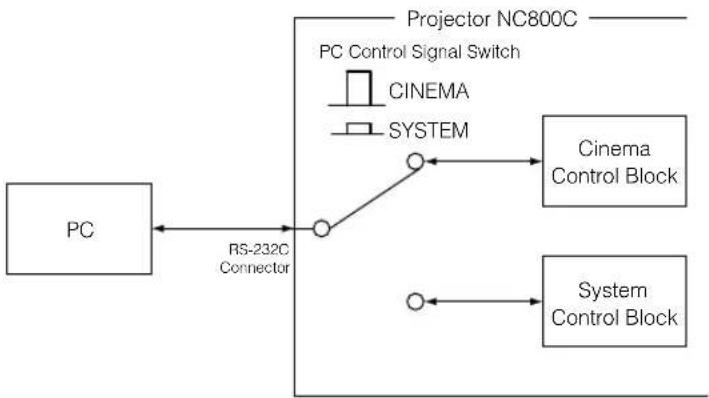
flowchart
graph TD
    A["PC"] -->|RS-232C Connector| B((Node))
    B --> C["Projector NC800C"]
    C --> D["Cinema Control Block"]
    C --> E["System Control Block"]
    D --> F["PC Control Signal Switch"]
    E --> G["SYSTEM"]
6-7-2. Remote control input connector (REMOTE IN) (Stereo mini)
Connected with the projector's remote control the accessory remote cable.
When the remote cable is connected to this connector, the remote cable connector operates with the following functions.
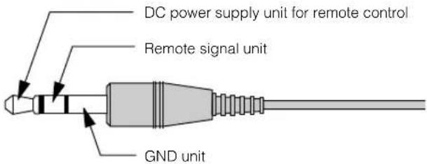
The DC voltage supplied from the projector to the remote control is approximately +4.0 V.
NOTE
The remote control cable is connected first to the remote control, then to the projector head.
The leading end of the remote control cable is the power supply unit, so be careful not to touch the other end of the remote cable to the projector head or other devices while only the remote control cable is connected to the projector.
TIP
Even if the remote cable power supply unit and GND unit (such as the projector head) should short, the protective function inside the projector will activate to prevent the shorted cable from damaging the projector.
6-7-3. LAN port (LAN-A, LAN-B) (RJ-45)
Use Ethernet 10Base-T/100Base-TX UTP (Unshielded Twist Pair cable) to connect with a video server or a PC. A switching hub exists inside, so there are no functional differences of either the LAN-A or LAN-B ports.
Internal Configuration Diagram of LAN Port
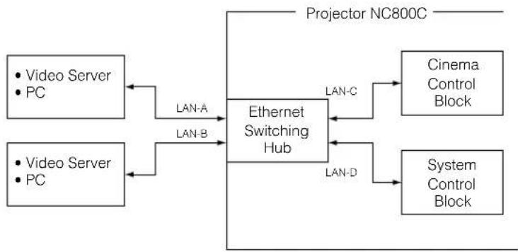
flowchart
graph TD
    A["Video Server PC"] -->|LAN-A| B["Ethernet Switching Hub"]
    C["Video Server PC"] -->|LAN-B| B
    B -->|LAN-C| D["Cinema Control Block"]
    B -->|LAN-D| E["System Control Block"]
    B --> F["Projector NC800C"]
6. Appendix
6-7-4. External control connector (GP I/O) (D-Sub 37 pin)
It is possible to control the projector with an external device and to control the external device from the projector using an external control connector (GP I/O: General Purpose I/O Ports). Each pin is electrically separated from the projector internal circuits by a photo-coupler. 8 port input and 8 port output are available.
Please contact your dealer/distributor regarding how to use and to operate them.
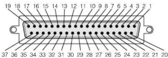
Pin view of female connector
| Pin No. | Signal Name | I/O | Pin No. | Signal Name | I/O |
| 1 | Ext_GPIN_1_P | Input | 20 | Ext_GPIN_1_N | Input |
| 2 | Ext_GPIN_2_P | Input | 21 | Ext_GPIN_2_N | Input |
| 3 | Ext_GPIN_3_P | Input | 22 | Ext_GPIN_3_N | Input |
| 4 | Ext_GPIN_4_P | Input | 23 | Ext_GPIN_4_N | Input |
| 5 | Ext_GPIN_5_P | Input | 24 | Ext_GPIN_5_N | Input |
| 6 | Ext_GPIN_6_P | Input | 25 | Ext_GPIN_6_N | Input |
| 7 | Ext_GPIN_7_P | Input | 26 | Ext_GPIN_7_N | Input |
| 8 | Ext_GPIN_8_P | Input | 27 | Ext_GPIN_8_N | Input |
| 9 | Ext_GPOUT_1_P | Output | 28 | Ext_GPOUT_1_N | Output |
| 10 | Ext_GPOUT_2_P | Output | 29 | Ext_GPOUT_2_N | Output |
| 11 | Ext_GPOUT_3_P | Output | 30 | Ext_GPOUT_3_N | Output |
| 12 | Ext_GPOUT_4_P | Output | 31 | Ext_GPOUT_4_N | Output |
| 13 | Ext_GPOUT_5_P | Output | 32 | Ext_GPOUT_5_N | Output |
| 14 | Ext_GPOUT_6_P | Output | 33 | Ext_GPOUT_6_N | Output |
| 15 | Ext_GPOUT_7_P | Output | 34 | Ext_GPOUT_7_N | Output |
| 16 | Ext_PROJ_GOOD_P | Output | 35 | Ext_PROJ_GOOD_N | Output |
| 17 | NC | - | 36 | NC | - |
| 18 | Reserve | - | 37 | Reserve | - |
| 19 | Reserve | - | - | - | - |
Input Connector
GP I/O Connector Inside Projector

- Use with External Control Mode
You can use the GP I/O input port to turn the projector power on and off, to control video mute and to switch signals (switching the input connector and image adjusting data).
| Pin No. | Photo-coupler ON / OFF | Function | ||
| 1-20 | OFF | External control mode OFF | ||
| ON | External control mode ON | |||
| 2-21 | OFF | Power off | ||
| ON | Power on | |||
| 3-22 | OFF | Image mute off | ||
| ON | Image mute on | |||
| 4-235-246-25 | 6-25 | 5-24 | 4-23 | The following functions are used, depending on the combination of the input connectors. |
| OFF | OFF | OFF | Selects title registered to MACRO 1. | |
| OFF | OFF | ON | Selects title registered to MACRO 2. | |
| OFF | ON | OFF | Selects title registered to MACRO 3. | |
| OFF | ON | ON | Selects title registered to MACRO 4. | |
| ON | OFF | OFF | Selects title registered to MACRO 5. | |
| ON | OFF | ON | Selects title registered to MACRO 6. | |
| ON | ON | OFF | Selects title registered to MACRO 7. | |
| ON | ON | ON | Selects title registered to MACRO 8. | |
| 7-26 | - | - | - | Used internally. |
| 8-27 | - | - | - | Used internally. |
NOTE
When in use in the External Control Mode, it is not possible to turn the power on and off from the remote control, operation panel or menus, to mute the video, or to switch titles.
Output Connector
GP I/O Connector Inside Projector
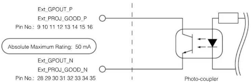
6. Appendix
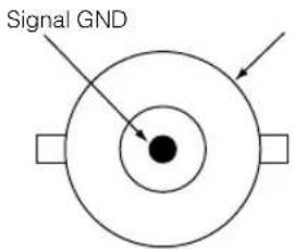
6-7-5. SDI-A, SDI-B (HD-SDI input connector) (BNC)
This is a signal input connector (SMPTE 292/HDSDI) for CINEMA.
The SMPTE 292/HD-SDI transfers HDTV signals with 1.5 GHz digital serial signals, so use a 75 Éd coaxial cable having a thickness and characteristics higher than 5C-FB, and use a BNC for the connector.
6-7-6. DVI-A, DVI-B (DVI digital Input connector) (DVI-D 24 pin)
This is a single link DVI input connector that is compliant with hot plug detect (HPD). Use a single link cable. Noise may be generated in the video if you use a dual link cable.
EDID is available even when the projector is switched off.
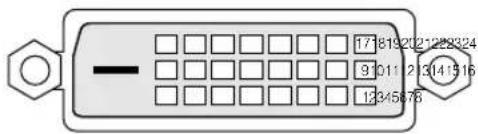
Pin view of female connector
| Pin No. | Signal Name | Pin No. | Signal Name |
| 1 | TMDS Data 2- | 13 | unused |
| 2 | TMDS Data 2+ | 14 | +5V Power |
| 3 | TMDS Data 2 Shield | 15 | Ground |
| 4 | Unused | 16 | Hot Plug Delect* |
| 5 | Unused | 17 | TMDS Data 0- |
| 6 | DDC Clock | 18 | TMDS Data 0+ |
| 7 | DDC Data | 19 | TMDS Data 0 Shield |
| 8 | Unused | 20 | unused |
| 9 | TMDS Data 1- | 21 | unused |
| 10 | TMDS Data 1+ | 22 | TMDS Clock Shield |
| 11 | TMDS Data 1 Shield | 23 | TMDS Clock+ |
| 12 | Unused | 24 | TMDS Clock- |
6-8. Related products list
| Product name | Model name | |
| Lens | Zoom Lens 1.45 to 1.8:1 | L2K-14ZM |
| Zoom Lens 1.8 to 2.4:1 | L2K-18ZM | |
| Zoom Lens 2.2 to 3.0:1 | L2K-22ZM | |
| Zoom Lens 3.0 to 4.3:1 | L2K-30ZM | |
| Anamorphic lens | Anamorphic lens 1.25 | AL 1.25 |
| Anamorphic lens manually operated turret | Anamorphic turret | AS 1.25 |
| Lamp house module (excluding lamp) | Lamp house module | IS8LH-E |
| Lamp | Lamp | IS8LP4-E |
| Wireless LAN card | Wireless LAN Card NWL-100 Series | (Note) |
(Note) Please contact your dealer/distributor for details on product and model names.
(MEMO)


- WARNING
- CAUTION
- DOC compliance Notice
- Important Safeguards
- Installation
- Power Supply
- Cleaning
- Fire and Shock Precautions
- Lamp Caution: Please read before operation
- WARNING:
- Remote Control Precautions
- Disposing of your used product
- For questions relating to unclear points or repairs
- In Europe
- In North America
- 1.What's in the Box? and the Names of the Projector Parts...... 2
- Installation and Connection .... 14
- 3.Projection of Images (Basic Operation) 18
- 4.Using Menus 25
- 5.Maintenance of Your Projector 34
- Appendix 35
- 1.
- What's in the Box? and the Names of the Projector Parts
- 1-1. Features
- - Up-to-date functions of DLP Cinema ® available
- 1-2. What's in the Box?
- TIP
- 1-3. Names of the Projector Parts
- 1-3-1. Front of the projector
- 1-3-2. Rear of the projector
- Air inlet
- Air outlet
- Power cord
- Function ground
- Main power switch
- Lamp cover
- NOTE
- 1-3-3. Connection terminals
- Remote control input terminal (REMOTE IN) (Stereo mini)
- PC control signal switch (CINEMA/SYSTEM)
- PC control terminal (RS-232C) (D-Sub 9P)
- PC card slot
- USB port (USB) (type A)
- HDSDI A input terminal (SDI-A) (BNC)
- HDSDI B input terminal (SDI-B) (BNC)
- DVI-D A input terminal (DVI-A) (DVI-D 24P)
- 1-3-4. Control panel
- Remote control light reception unit
- BACKLIGHT switch
- MMS STATUS indicator
- LCD screen
- POWER button
- POWER indicator
- STATUS indicator
- CTL (MACRO) button
- What's in the Box? and the Names of the Projector Parts
- 1 to 8 buttons
- CTL (LAMP) button
- LAMP +/- buttons
- MENU button
- [MENU CTL] UP/DOWN/LEFT/RIGHT buttons
- CANCEL button
- ENTER button
- FOCUS +/- buttons
- ZOOM +/- buttons
- [LENS CTL] UP/DOWN/LEFT/RIGHT buttons
- CTL (LENS) button
- DOUSER button
- 1-4. Names on the Remote Control
- POWER ON button
- POWER OFF button
- Numeric buttons (1 to 0 buttons)
- TEST button
- KEYSTONE / R button
- AMPLITUDE / G button
- ENTRYLIST / B button
- POSI / LENS button
- PICT / SHUT button
- MENU button
- SELECT ▼▲◀▶ buttons
- ENTER button
- CANCEL button
- FOCUS +/- buttons
- ZOOM +/- buttons
- CTL button
- Back light switch
- Inserting the batteries
- Effective range of the remote control
- Using the remote control cable
- Notes for use of the remote control
- Installation and Connection
- 2-1. Steps for setting up and connecting
- 2-2. Connecting the image input terminals
- 2-3. Connecting the various control terminal
- 2-4. Connecting the power cord
- 3.
- Projection of Images (Basic Operation)
- 3-1. Steps of projecting images
- 3-2. Turning your projector on
- Projection of Images (Basic Operation)
- Press the POWER button on the control panel of your projector three seconds or longer.
- 3-3. Selecting the title of input signal
- 3-4. Adjusting the position and the size of projected screen
- 3-4-1. Displaying the test pattern
- 3-4-2. Adjusting the position of the projected screen (Lens shift)
- 3-4-3. Fine adjustment of the size of the projected screen (Zoom)
- 3-4-4. Focusing the projected screen (Focus)
- 3-4-5. Adjusting the brightness of the projected screen (Lamp output)
- 3-5. Turning your projector off
- Press the POWER button on the projector control panel for three seconds or longer.
- When the projector has entered the standby state, turn the main power switch on the projector head to off.
- Turn off the AC power to the projector head.
- 4.
- Using Menus
- 4-1. Basic operation with adjustment menus
- 4-1-1. Screen display
- Using Menus
- When in standby
- When power is turned on
- When the power is turned off
- 4-1-2. Operating menus
- Press the [MENU CTL] DOWN button.
- Press the [MENU CTL] LEFT/RIGHT button to select the submenu "Version."
- Press the [MENU CTL] DOWN button.
- Press the [MENU CTL] LEFT/RIGHT button to select the submenu "Data."
- Press the [MENU CTL] UP button several times.
- 4-1-3. How to enter alphanumeric characters
- [Example of Entry]
- 4-2. Table of adjustment menus
- 4-3. Title Select
- 4-3-1. Title select (Title Memory)
- 4-3-2. Test Pattern
- 4-4. Configuration
- 4-4-1. Lamp Setup
- Adjust
- Feedback
- 4-5. Title Setup
- 4-6. Information
- 4-6-1. Lamp
- Output
- 4-6-2. Macro Key
- 4-6-3. Usage
- 4-6-4. Error Code
- 4-6-5. Version
- 4-6-6. IP Address
- 4-6-7. MMS Status
- 5.
- Maintenance of Your Projector
- 5-1. Cleaning the Cabinet
- 5-2. Cleaning the Lens
- 6.
- Appendix
- 6-1. Troubleshooting
- 6-1-1. Problems and where to check
- Appendix
- 6-2. Indicator display list
- 6-2-1. POWER indicator
- 6-2-2. STATUS indicator
- 6-2-3. MMS STATUS indicator
- 6-3. Error code list
- 6-4. Operation using an HTTP browser
- 6-4-1. Overview
- 6-4-2. Preparation before use
- 6-4-3. Handling of the address for operation via a browser
- 6-4-4. Structure of the HTTP server
- 6-5. Outline Drawing
- 6-6. Specifications
- 6-7. Pin Assignment and Functions of Terminal
- 6-7-1. PC CONTROL connector (D-Sub 9 pin)
- Internal Configuration Diagram of RS-232C Communication System
- 6-7-2. Remote control input connector (REMOTE IN) (Stereo mini)
- 6-7-3. LAN port (LAN-A, LAN-B) (RJ-45)
- Internal Configuration Diagram of LAN Port
- 6-7-4. External control connector (GP I/O) (D-Sub 37 pin)
- Input Connector
- - Use with External Control Mode
- Output Connector
- 6-7-5. SDI-A, SDI-B (HD-SDI input connector) (BNC)
- 6-7-6. DVI-A, DVI-B (DVI digital Input connector) (DVI-D 24 pin)
- 6-8. Related products list
Brand : NEC
Model : NC800C
Category : Projector