E872 - Elliptical bike SportsArt - Free user manual and instructions
Find the device manual for free E872 SportsArt in PDF.


| Product Type | Elliptical Bike |
| Brand | SportsArt |
| Model | E872 |
| Dimensions (L x W x H) | 82 x 32 x 65 inches (208 x 81 x 165 cm) |
| Weight | 350 lbs (159 kg) |
| Max User Weight | 450 lbs (204 kg) |
| Power Supply | Self-powered via Eco-Powr™ generator |
| Resistance System | Magnetic two-stage drive, 20 levels |
| Stride Length | 20-24 inches adjustable |
| Display | Large LCD with time, distance, calories, heart rate, RPM |
| Heart Rate Monitoring | Touch sensors and telemetry (Polar compatible) |
| Programs | 12 preset workouts, custom, HR control |
| Special Features | Eco-Powr™ energy-saving, low-impact motion |
| Pedal Design | Anti-slip, oversized footplates with heel pads |
| Handlebar Design | Multi-position ergonomic handlebars |
| Transport Wheels | Front-mounted for easy mobility |
| Leveling Feet | Adjustable for stability on uneven floors |
| Warranty | 5 years frame, 2 years parts, 1 year labor |
| Usage | Commercial (light commercial to home) |
| ATA Number | Not applicable |
| Assembly Required | Yes, with included tools and manual |
| Certifications | CSA, FCC, ISO 9001 |
Frequently Asked Questions - E872 SportsArt
User questions about E872 SportsArt
0 question about this device. Answer the ones you know or ask your own.
Ask a new question about this device
Download the instructions for your Elliptical bike in PDF format for free! Find your manual E872 - SportsArt and take your electronic device back in hand. On this page are published all the documents necessary for the use of your device. E872 by SportsArt.
USER MANUAL E872 SportsArt
Congratulations on your purchase of one of the finest exercise products on the market today, the SportsArt E872 elliptical trainer. Constructed of high quality materials and designed for years of reliable usage, this product was made to become an integral part of your commercial fitness venue.
Before this product is assembled or operated, we recommend that you familiarize yourself with this manual. Understanding the correct assembly and operation of this product will help ensure that exercisers obtain their fitness goals safely and successfully.
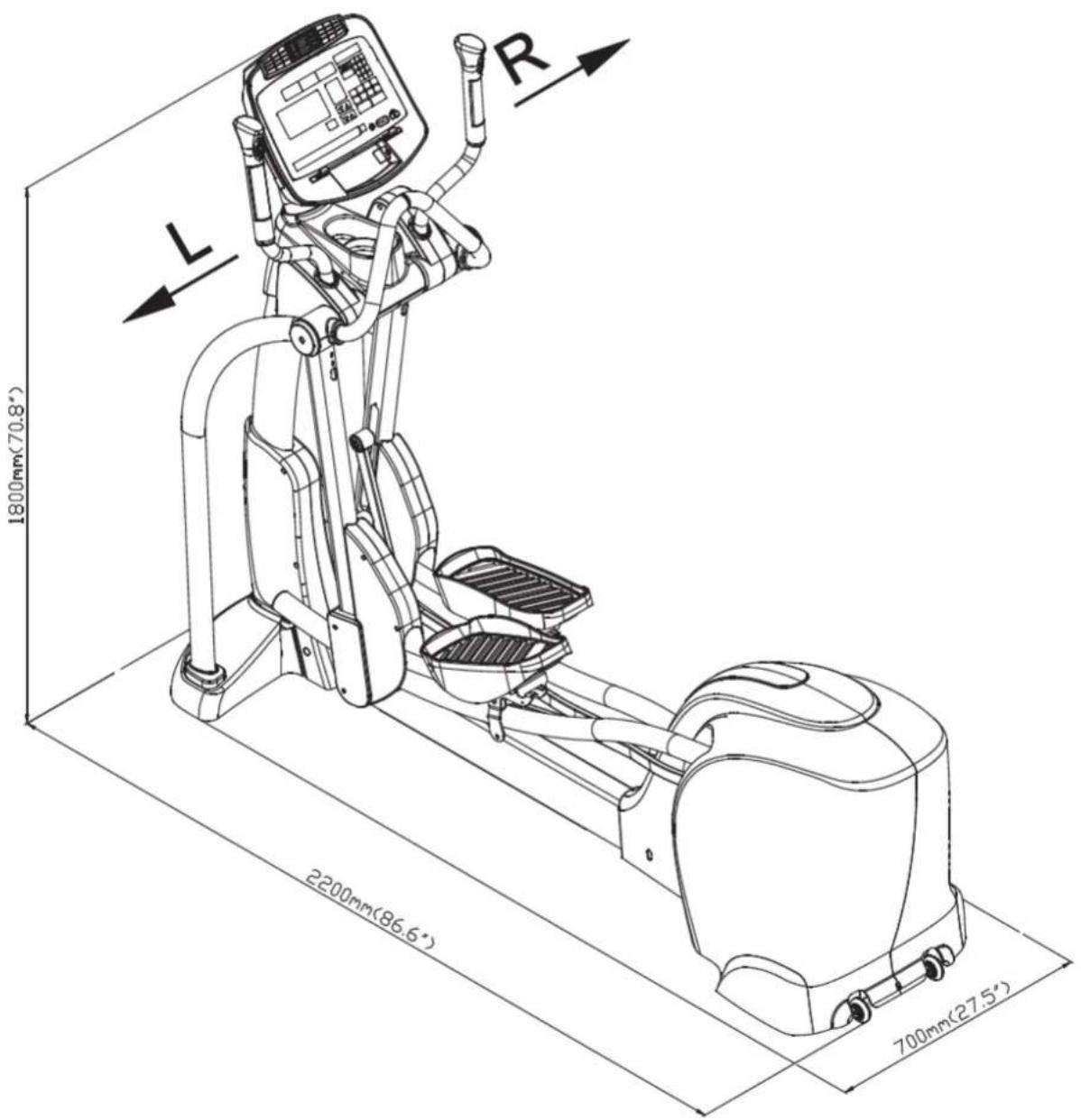
text_image
1800mm(70.8°) 2200mm(86.6°) 700mm(27.5°)2. IMPORTANT SAFETY PRECAUTIONS
Your SportsArt elliptical trainer was designed and built for optimum safety. However certain precautions apply whenever you use your elliptical trainer.
Please read the instruction manual before assembly and operation. Also, please note the following safety precautions:
- Please read the instruction carefully and install the elliptical trainer as instructed.
- Assemble and operate the elliptical trainer on a solid, level surface; DO NOT use outdoors or near water.
- Never allow children on or near the elliptical trainer.
- Check the elliptical trainer before every use. Make sure all parts are assembled, and all fasteners are tightened. DO NOT use the elliptical trainer if the unit is disassembled in any way.
- Keep your hands away from moving parts.
- Wear proper workout clothing; DO NOT wear loose clothing. DO NOT wear shoes with leather soles or high heels. Tie all long hair back. Do not go barefoot on this Product.
- Be careful when mounting and dismounting the unit.
- The elliptical trainer may or may not stop immediately if any object becomes caught or impedes normal motion.
- DO NOT use accessories that are not specifically recommended by the manufacturer. Such parts might cause injuries or cause the unit to fail.
- Close supervision is necessary when this elliptical trainer is used by, on, or near children, invalids, or disabled persons.
- Use this elliptical trainer only for its intended use as described in this manual.
- Never operate this elliptical trainer if it has been damaged in any way If it is not working properly, or has been dropped or damaged, contact your dealer.
- Keep all air ventilation areas free of blockage.
- Never drop or insert any object into any opening.
- DO NOT operate where aerosol (spray) products are being used or where oxygen is being administered.
- The general user weight limit for this elliptical trainer is 227 kg (500 lb.) Note that at resistance level 20 this product meets standards for users of up to 150 kg (330 lb.).
- This elliptical trainer is not intended for use by persons (including children) with reduced physical, sensory or mental capabilities, or lack of experience and knowledge, unless they have been given supervision or instruction concerning use of the elliptical trainer by a person responsible for their Safety.
- Children should be supervised to ensure that they do not play with the elliptical trainer.
CAUTION
If you feel any pain or abnormal sensation, STOP YOUR WORKOUT and consult your physician immediately. Work within your recommended exercise level. DO NOT work to exhaustion.
Before beginning any exercise program, you should consult with your doctor. It is recommended that you undergo a complete physical examination.
DO NOT step onto the highest footplate first. While holding onto supports for stability, step onto the lowest footplate.
Note: This equipment has been tested and found to comply with the limits for a Class B digital device, pursuant to part 15 of the FCC Rules. These limits are Designed to provide reasonable protection against harmful interference in a residential installation. This equipment generates, uses and can radiate radio frequency energy and, if not installed and used in accordance with the instructions, may cause harmful interference to radio communications. However, there is no guarantee that interference will not occur in a particular Installation.
If the user desires to correct the interference, it is at the user's own expense.
In this manual, the words "left" and "right" are used in reference to parts and the product As such, the words "left" and "right" equate to the exerciser's left and right sides respectively. Also, for brevity, the word "screws" is used in some cases where washers, screws, and other hardware are involved.
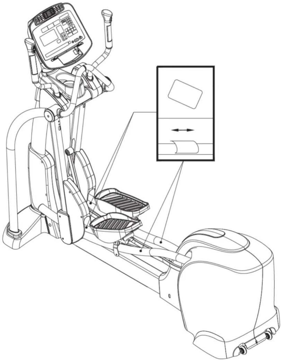
If you are a French speaking person in North America, please place the sticker contained in the owner's manual on the product as shown. Customers in other areas will not receive the sticker.
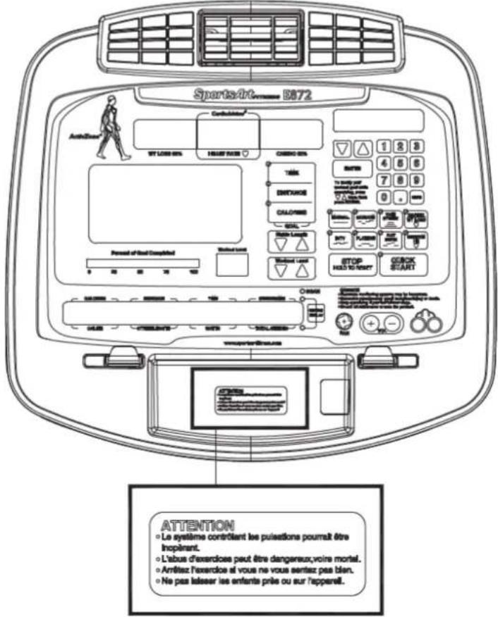
text_image
Technical diagram of a stationary exercise machine with labeled components such as A1 through A11| Assembly Parts | |||||
| No. | Name Qty | No. | QtyD | ||
| A1 | Main frame | 1 | A7 | Roller cover, left | 2 |
| A2 | Stationary handlebar | 1 | A8 | Support tube, left | 1 |
| A3 | Pedestal covers, left and right | 1 | A9 | Support tube, right | 1 |
| A4 | Joint cover, left | 1 | A10 | Footplate | 1 |
| A5 | Joint cover, right | 1 | A11 | Hardware kit | 1 |
| A6 | Right roller cover | 2 | |||
description
| Parts in the Hardware Kit | ||||
| No. | Name Qty | Specification | Notes | |
| Mushroom top inner hex screw | 6 | M10*P1.5*L25 | ||
| 10 | Spring washer | 6 | M10 | |
| Washer | 6 | D21*d10.5*t1.5 | ||
| 11 | Stride adjustment linkage cover, left and right | 2 | ||
| 12 | Hex nut | 2 | M10*P1.5 | |
| Stopper | 2 | 30-30 | ||
| 13 | Phillips screw | 4 | M4*L12 | |
| L-shaped Allen wrench | 1 | M4 | ||
| L-shaped Allen wrench | 1 | M5 | ||
| T-shaped Allen wrench | 1 | M6 | ||
| Double open-end wrench | 1 | (8*17) | ||
| Double open-end wrench | 1 | (14*15) | ||
| Screwdriver handle | 1 | green | ||
| Screwdriver bit | 1 | Flat and Phillips | ||
| Parts on the Product | |||
| No. | Name | Specification | Notes |
| 21 | Phillips screw | M4*P0.7*L8 | |
| 22 | Inner hex screw | 5/16"*L2-1/4" | |
| Flat washer | D20*d8*t2.0 | ||
| 23 | Inner hex screw | M6*L15 | |
| Handlebar washer | D20*d7*t2.0 | ||
| 24 | Mushroom top inner hex screw | M8*L15 | |
| Spring washer | M8 | ||
| 25 | Inner hex screw | M6*L15 | |
| Handlebar washer | D20*d7*t2.0 | ||
| 26 | Phillips screw | M5*P0.8*L15 | |
| 27 | Mushroom top Phillips screw | M5*0.8*L12 | |
| 28 | Mushroom top inner hex screw | M5*L16 | |
STEP 2 Assemble Moving Parts
Follow instructions (a) through (e) to install the moving parts.
(a) Remove screws (21) from the stride arm attached to the main frame (A1).
(b) Once slip the glide rail into (Part A), then place the pedal carriage lightly on the glide rail support.
(c) Connect the guide roller (14) on the bottom of the glide rail. (Please note the direction to insert the screw is from outside to inside)
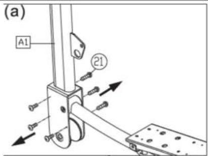
text_image
(a) A1 21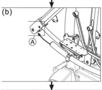
text_image
(b) A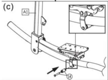
text_image
(c) A1 14STEP 2 Assemble Moving Parts (continued)
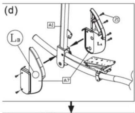
(d) Separate the roller covers (A7). Snap them together into place on the product. Then secure them with screws (21).
(e) On the left side of the product, remove the screw (22) from the stride adjustment linkage. Place the stride adjustment linkage into place on the bushing, and use the screw (22) to secure it into place. Then press the stride adjustment linkage cover (11) into place. Carry out the same procedure on the right side of the product as well.

Consult the manual and follow all assembly instructions carefully. Please note that incorrect assembly may present a danger to the exerciser, will damage the elliptical and void the warranty.
STEP 3 Install the Support Tubes
Follow steps (a-b) to secure the left and right support tubes into place.
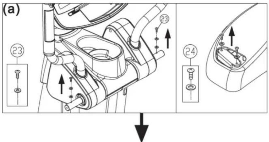
(a) Remove support tube screws (23) (24) from the main frame (A1).
(b) Insert left and right support tubes (A8, A9) onto the axle and base, and loosely secure them in place with the screws (23, 24).
text_image
(a) ②3 ②3 ②4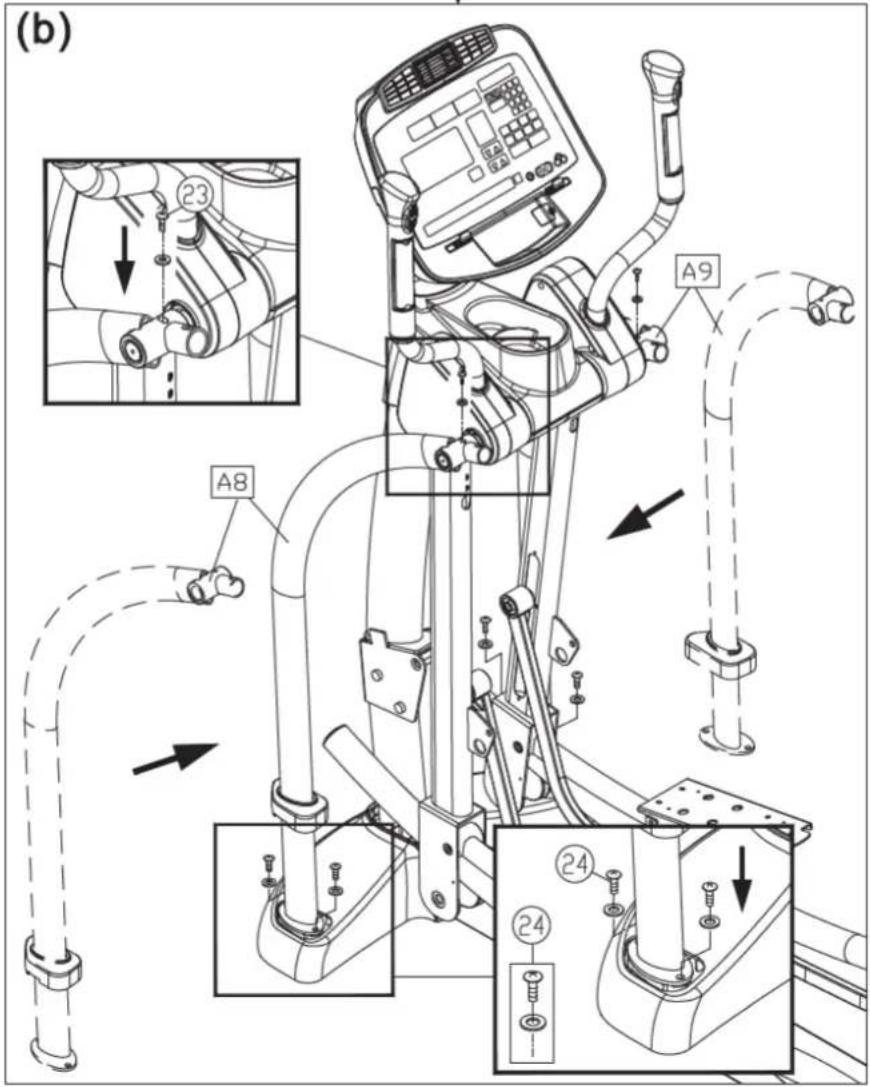
text_image
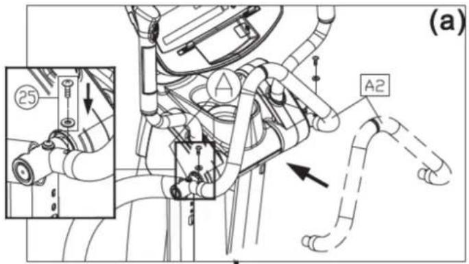
(b) A8 A9 23 24 24STEP 4 Install the Stationary Handlebar
Follow steps (a-c) to install the stationary handlebar.
(a) Remove screws (25) from the left and right support tubes (A8, A9). Insert the stationary handlebars (A2) in place. Use screws (25) to secure them. Fully secure screws in area A.
(b) Remove screws (26) from the sides of the left and right support tubes (A8, A9). Snap axle covers (A4, A5) into place on left and right sides. And use screws (A6) to secure them.
(c) After securing screws in area B, slide support tube covers down onto the base.
text_image
(a) A A2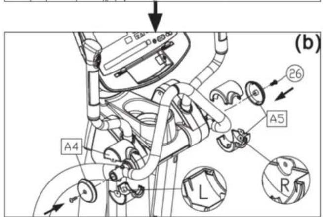
text_image
(b) A4 26 A5 L R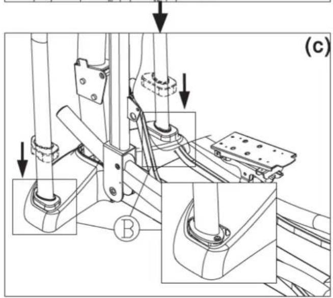
text_image
(c)STEP 5 Install Stoppers and Covers
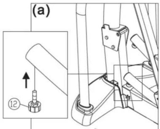
Follows steps (a-c) to install glide rail stoppers.
(a) Screw stoppers (12) into place on both glide rails.
(b) Remove screws (27) from the frame (A1).
(c) Snap pedestal covers (A3) together on the unit. Loosely secure screws (27), followed by screws (13). After all screws are in place, secure them.
text_image
(a) ⑫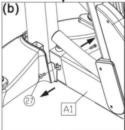
text_image
(b) ②7 A1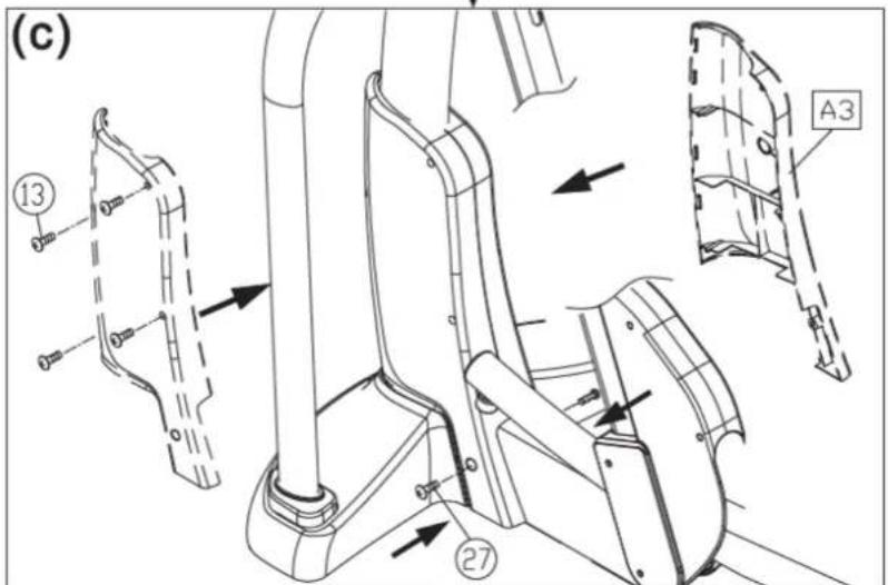
text_image
(c) 13 27 A3STEP 6 Install the Footplate
Follow steps (a-c) to install the footplate.
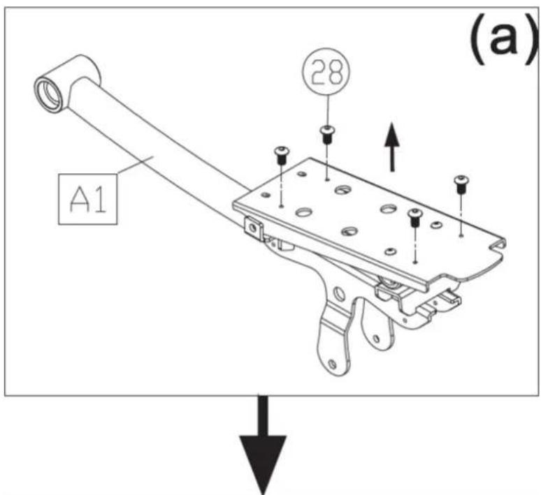
(a) Remove screws (28) from the pedal carriage as shown.
(b) Push upward on the nibs in the cushion, and lift the front and back part of the cushion to expose four screw holes. (Note: Maintain the connection at pivot point A.) Use screws (28) to secure the footplate to its mount on the pedal carriage. First secure area B, then secure area C. Insert the nibs on the cushion into the Holes on the footplate on the pedal carriage (A10).
text_image
(a) A1 28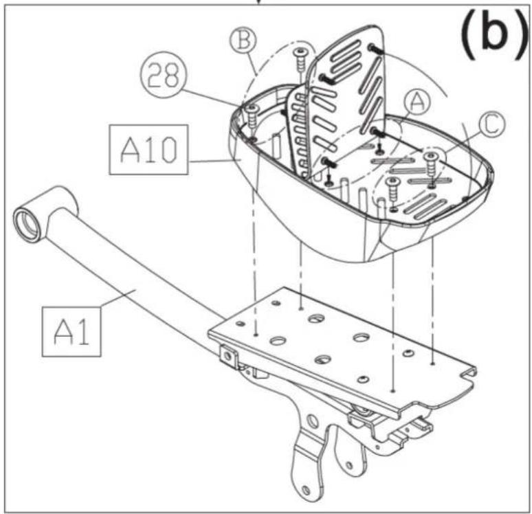
text_image
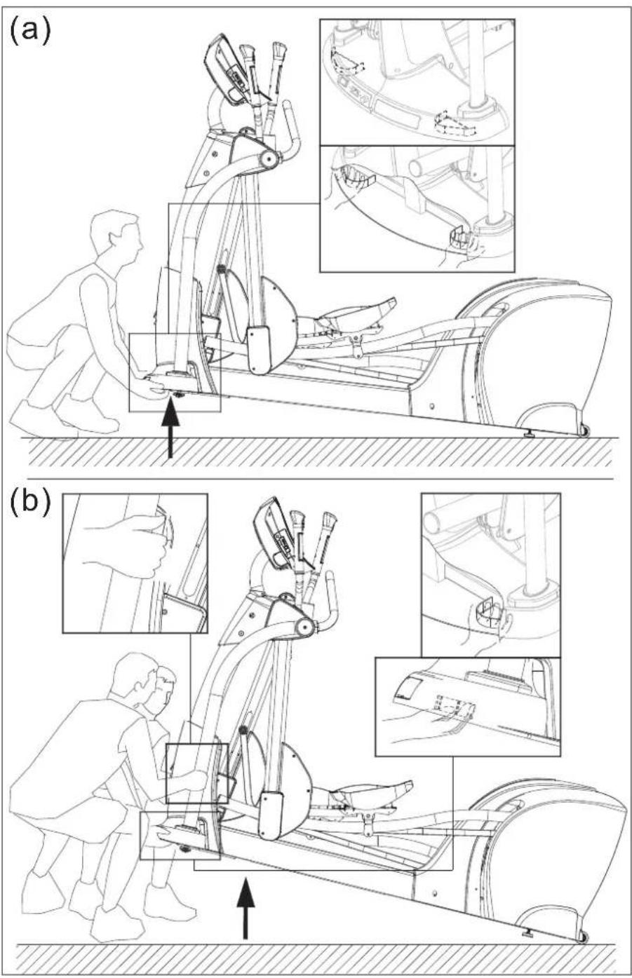
(b) A1 A2 B C 28 A10STEP 7 Move the Product into Place
(a) For one person: Grip the front base of the product and lift upward, then push the product into location for use. Be careful to avoid pinching fingers when setting the product down.
(b) For two people: Have one person grip the front base of the product while the other person grips the support tubes (A8, A9). With both people lifting and stabilizing the unit, roll it into place for use. Be careful to avoid pinching fingers when setting the product down.
text_image
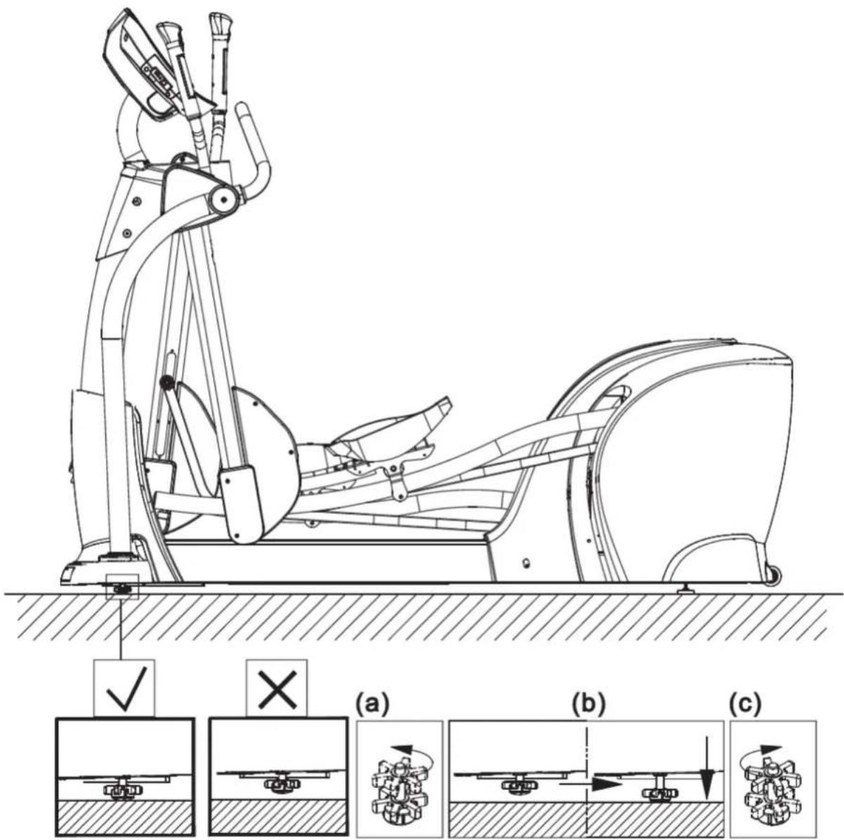
(a) (b)STEP 8 Level the Product
For the user's safety and the product's proper functioning, this elliptical trainer must sit level on a flat floor. If necessary, please adjust product levelers by following steps (a-c).
(a) Loosen the leveler nut.
(b) Rotate the leveler foot downward so it firmly touches the floor.
(c) To secure this position, secure the leveler nut upward against the product frame.
text_image
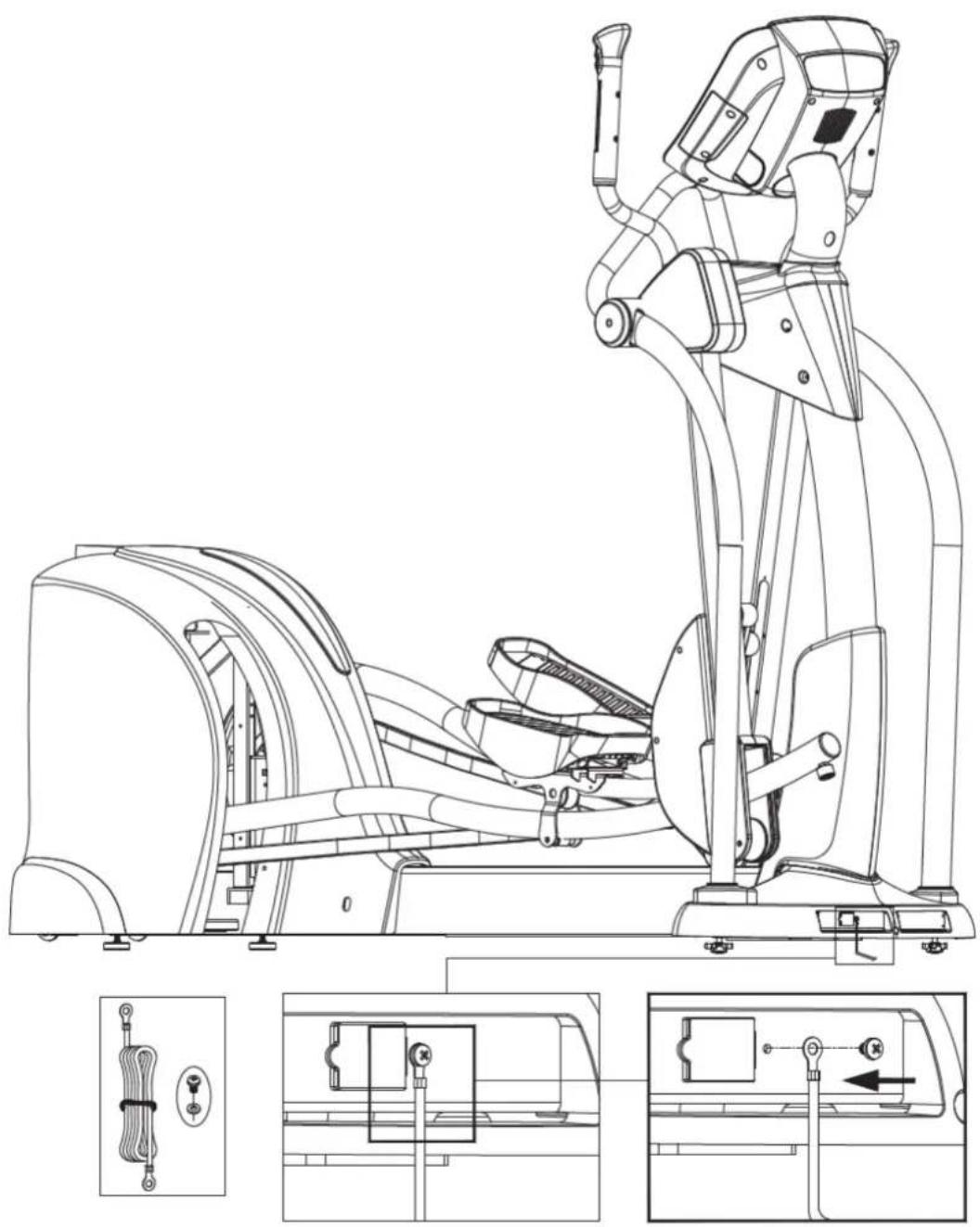
Technical diagram of a stationary exercise machine with labeled cross-sectional views (a, b, c) and mechanical assembly diagrams.STEP 9 Ground Wire Installation
Note: A ground wire and the following instructions are required by European safety standards. The ground wire is not required by North American safety standards.
To avoid electric shock and current leakage, this product has an exterior ground wire. For your safety, connect this ground wire to the unit and to the building ground. Installation instructions: Please use screws and washers to secure one end of the ground wire to the product frame as shown and the other end to the building electrical ground.
natural_image
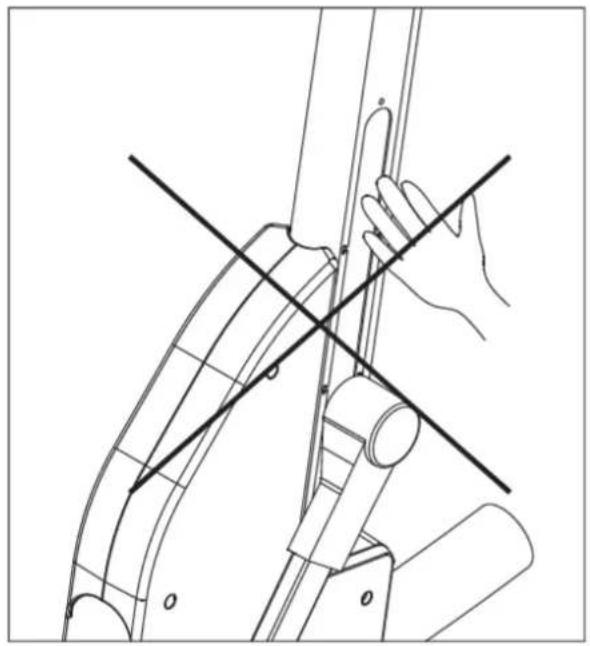
Technical line drawing of a stationary exercise machine with internal components and external wiring (no text or symbols)STEP 10 Beware of Moving Parts
This product has moving parts that could be a danger to people and animals. During use, do not insert hands or other objects into the stride adjustment slot, the opening in the rear cover, or other areas in which such action might present a hazard.
natural_image
Technical line drawing of a mechanical assembly with intersecting lines and components (no text or symbols)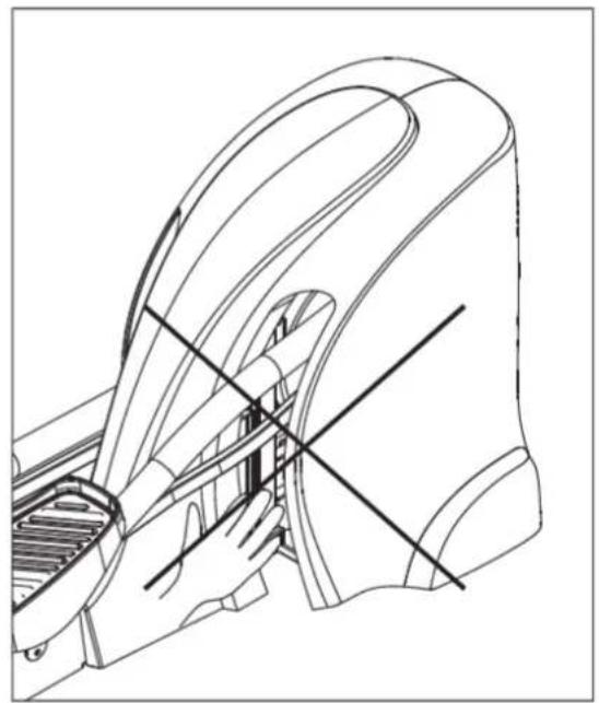
natural_image
Technical line drawing of a mechanical component with internal channels and alignment lines (no text or symbols)5. UNDERSTANDING THE E872 DISPLAY CONSOLE
DISPLAY Specifications
• Workout level (resistance level): 1 - 20
• Time: 00 - 99 : 59
• Distance: 0.00 - 9999 km or mile
• Calories: 0.0 - 9999 kcal
• Calories per hour: 0.0 - 9999 kcal
- Programs: MANUAL, RANDOM, VARI-STRIDE, CARDIO/WT LOSS, INTV, PLATEAU, FAT BURN, CUSTOM HR
• Heart rate range: 40 - 250 beats per second
• Strides/minute (SPM): 5 - 120
- Watts: 0 - 9999
• Total strides (accumulated stride count): 0 - 9999
• Stride length: 17 - 29 inch (450 - 730 mm)
DISPLAY Overview
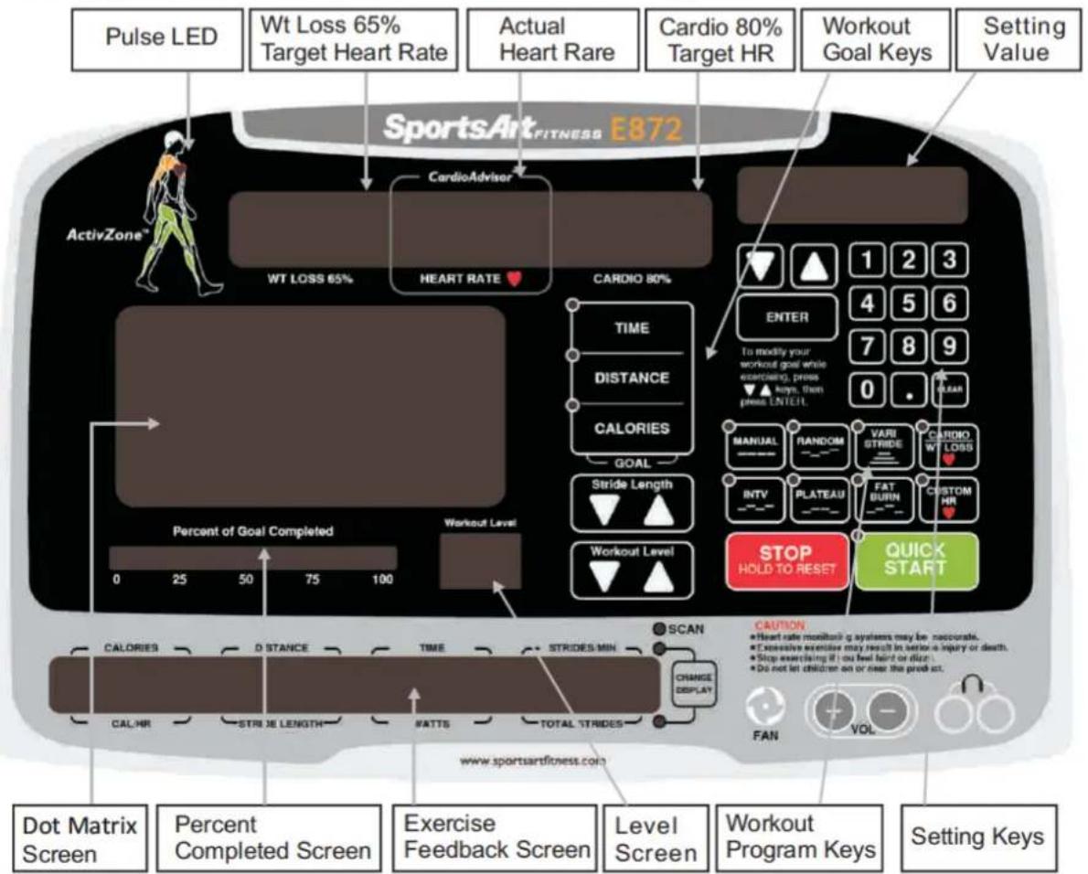
The E872 elliptical trainer is designed for user convenience. With better feedback about your workout, you get better results. The following explains the display key and window functions. Please read this manual, understand the display functions, and thereby get optimum enjoyment and benefit from this product.
text_image
Pulse LED Wt Loss 65% Target Heart Rate Actual Heart Rare Cardio 80% Target HR Workout Goal Keys Setting Value SportsArt_FITNESS E872 CardioAdviser ActivZone™ WT LOSS 65% HEART RATE ♥ CARDIO 80% TIME DISTANCE CALORIES GOAL Stride Length WORKOUT Level Percent of Goal Completed 0 25 50 75 100 Percent of Goal Completed 0 25 50 75 100 WEATS TOTAL STRIDES POST HOLD TO RESET QUICK START CAUTION ● Heart rate monitor g systems may be inaccurate. ● Excessive exercise may result in set-on a injury or death. ● Stop exercising if you feel hard or disc. ● Do not let children on or near the product. FAN VOL Dot Matrix Screen Percent Completed Screen Exercise Feedback Screen Level Screen Workout Program Keys Setting KeysDISPLAY Windows
The CardioAdvisor™ windows show heart rate goals, WT LOSS 65% and CARDIO 80%, and actual heart rate (center).
The exercise feedback screen shows usage prompts and workout information.
The dot matrix screen shows workout program illustrations.
The percent of goal completed screen shows percentage of goal completed.
The work level screen shows present resistance level.
The setting screen shows setting values and workout goal values.
DISPLAY Keys
Display key functions are introduced briefly below.
QUICK START - Press this key to start exercising without first entering age, weight, and other user information. In QUICK START mode, time values accumulate.
TIME - Press this key to make time your workout goal.
DISTANCE - Press this key to make distance your workout goal.
CALORIES - Press this key to make calories your workout goal.
ENTER - After making a selection, press this key to confirm your choice.
0-9 numeric keys - Press these keys to directly input numeric values, rather than pressing <▲/▼> keys.
Decimal < · > key - Press this key to insert a decimal point to setting values.
<▲/▼> keys - Press these keys to adjust settings up or down. Hold these keys to change settings more quickly.
CLEAR - When inputting setting values, press this key to delete settings to 0.
MANUAL - This key allows you to directly control resistance, via resistance keys.
FAT BURN - This workout program might well be called challenge. Choose from one to 20 stages, each with an increasing level of difficulty.
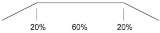
PLATEAU - This workout program gradually increases in difficulty, plateaus, then tapers off, in a 20-60-20 pattern.
VARI-STRIDE - This workout program automatically changes stride. Exercisers can select maximum stride.
RANDOM - Press this key to select one of an almost endless number of randomly generated workout programs.
INTERVAL - Press this key to select one of three interval programs: 1:1, 1:2, 2:2. Numbers represent minutes. For example, the 1:1 interval program would consist of one minute of rest, followed by one minute of work.
WT LOSS - A heart rate control program, the weight loss workout is designed to keep your pulse at the optimum rate for losing weight. Resistance settings change automatically to maintain a target heart rate as calculated by the formula (220-AGE)*0.65.
CARDIO - A heart rate control program, the cardio conditioning workout is designed to keep your pulse at the optimum rate for cardio conditioning. Resistance settings change automatically to maintain a target heart rate as calculated by the formula (220-AGE)*0.8.
CUSTOM HR - This heart rate control program allows you to set your own target heart rate.
STRIDE LENGTH < These keys adjust stride length. When you press either of these keys, the lower line of workout feedback in the exercise screen will light. The value in the STRIDE LENGTH screen will change to reflect actual stride position.
WORKOUT LEVEL ▲-▼Press these keys to change resistance settings.
STOP/HOLD TO RESET - In Workout mode, press
FAN - Press this key to activate the fan. There are four settings: off, low, medium, and high. Each time fan command keys are pressed, one of the following messages appears for two seconds:
| F | A | N | S | T | O | P | |||||||||
| F | A | N | L | O | W | ||||||||||
| F | A | N | M | I | D | ||||||||||
| F | A | N | H | I | G | H |
Note: On this self-powered product, strides per minute must exceed 25 SPM for the fan to operate. See Other Notes for related information.
CHANGE DISPLAY - This key controls the exercise feedback screen, which shows exercise feedback in two rows. The top row shows CALORIES, DISTANCE, TIME, RPM; the bottom row shows CAL/HR, METS, WATTS, SPEED. Corresponding LEDs light to indicate the active row of exercise feedback. When the SCAN indicator is lit, one row of exercise feedback appears for six seconds, then the other row appears for six seconds. Press the CHANGE DISPLAY key to toggle between scan and lock modes and to view top and bottom rows of exercise feedback.
DISPLAY Screens
Display screens provide information about workout programs and settings.
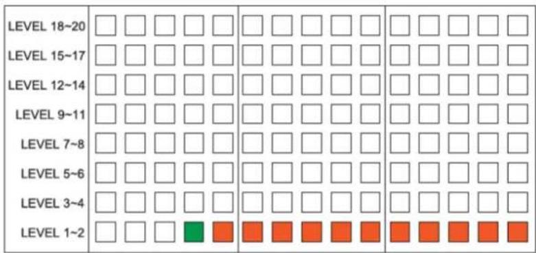
DOT MATRIX SCREEN When a workout begins, the dot matrix screen shows the workout illustration. Below is an example of the MANUAL program illustration.
text_image
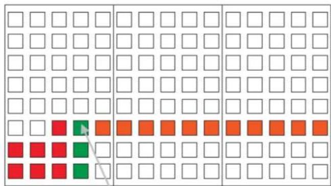
LEVEL 18~20 LEVEL 15~17 LEVEL 12~14 LEVEL 9~11 LEVEL 7~8 LEVEL 5~6 LEVEL 3~4 LEVEL 1~2Every 20 seconds, the illustration advances to the left by one column. Please see the illustration below.
text_image
Grid-based pattern with colored squares (red, orange, green) and a diagonal arrow, likely representing a logic or state transition.The completed portion of the workout is represented by the red columns. The active part of the workout is represented by the green column. The remaining portion of the workout is represented by the orange dots. When someone pedals on the cycle, the top green LED flashes (see the arrow). When no one pedals, the green column remains lit.
MESSAGE SCREEN The message screen shows workout feedback in two rows.
| CALORIES | DISTANCE | TIME | STRIDES/MIN | ||||||||||||
| X. | X. | X | X | X: | X | X | X | ||||||||
| CAL/HR | STRIDE LENGTH | WATTS | TOTAL STRIDES | ||||||||||||
| X | X | X | X | X | X | ||||||||||
Press the CHANGE DISPLAY key to toggle between either the top or bottom row of workout feedback. The LED in front of the activated row of feedback will light up. When the SCAN LED is lit, the active row of workout feedback changes every six seconds.
If no one pedals for six seconds, the following message will appear in the workout feedback screen:
| P | E | D | A | L | T | O | S | T | A | R | T |
WORKOUT GOAL The workout goal screen shows the percentage of workout completed. Before the exercise begins, the workout goal screen appears lit in orange. The orange area represents the workout that has yet to be completed.

bar
| Category | Value (%) | |---|---| | Row 1 | 0 | | Row 2 | 10 | | Row 3 | 20 | | Row 4 | 30 | | Row 5 | 40 | | Row 6 | 50 | | Row 7 | 60 | | Row 8 | 70 | | Row 9 | 80 | | Row 10 | 90 | | Row 11 | 100 | | Row 12 | 100 |After the workout begins, other colors appear.

bar
| Category | Value (%) | |---|---| | Red Bar | 25 | | Orange Bar | 30 | | Green Bar | 45 |Red represents the completed portion of the workout. The flashing green LED (center left) represents the present position in the workout. Orange represents the remaining part of the workout. While someone pedals, the green LED flashes. When no one pedals, the green LED remains lit.
The lit area is calculated based on a formula. For example, imagine that in a 30-minute workout you have exercised for ten minutes: 10 minutes/30 minutes * 100% = 33.3%.
There are three ways to activate this product, either by pedaling, or by pressing the QUICK START key, or by pressing a workout program key.
If you pedal without touching any keys, within two seconds, the following message will appear:
SELECT PROGRAM OR QUICKSTART
Press the QUICK START key to start exercising immediately without inputting any user information. The startup banner screen will appear as follows:
| S | P | O | R | T | S | A | R | T | - | E | 8 | 7 | 2 |
In QUICK START mode, the MANUAL indicator lights; resistance begins at level 1; time begins to accrue from 0:00; calorie information accrues based on the assumption of a 165 lb. (75 kg) user; target heart rate information is calculated based on the assumption of a 35-year-old user.
QUICK START operates much like MANUAL, except that manual mode requires you to establish a workout goal and user age and weight.
If you activate the bike by pressing the QUICK START key and then select a workout program, original workout feedback values are carried over to the new workout.
OPERATION Workout Program Setup
Unlike QUICK START, workout programs require the user to select a goal (either time, distance, or calories) and to input values for age and weight. Age values are used to calculate target heart rates. And weight values are used to calculate calorie expenditures.
Follow instructions below to prepare to use workout programs.
- Press a workout program key (MANUAL, RANDOM, VARI-STRIDE, CARDIO/WEIGHT LOSS, INTV, PLATEAU, FAT BURN, CUSTOM HR) to select a workout.
- "SELECT GOAL" will appear on the exercise feedback window. Press one of the workout goal keys, TIME, DISTANCE, or CALORIES, to select your workout goal. Follow instructions below in regard to time, distance, and calorie goals.
2A. TIME
After selecting time as the workout goal, "ENTER TME" appears in the message screen. Use </> keys in the setting area or numeric keys (0-9) to establish a workout time value. Press the ENTER key to confirm your choice and proceed to set the age value.
Notes about the TIME setting mode follow:
• The TIME setting range is 5:00 to 99:99, with a default value of 30:00.
- "PRESS ENTER" appears if, after selecting time, you do not press any key within six seconds.
- When </> keys in the setting area are pressed briefly, time values change by one digit each second. When </> keys in the setting area are held down, time values change by one digit every 0.2 seconds.
- When using numeric keys (0-9), digit placement is determined as shown in the following example:
① Press "3". The setting window will show the following:

② Press "4". The setting window will show the following:

③ Press "5". The setting window will show the following:

To return to the first step, while the minute value flashes, press any key.
- If the TIME value exceeds the range of 5:00 to 99:00 minutes, after the ENTER key is pressed, the setting window will show the default value of 30:00 minutes, and the following reminder will appear for two seconds:
| R | A | N | G | E | 5 | - | 9 | 9: | 0 | 0 |
- Press the CLEAR key at any time to clear settings to 0:00.
- The decimal < · > key does not operate during the time setting mode.
2B. DISTANCE
After selecting distance as the workout goal, use < keys in the setting area or numeric keys (0-9) to establish a workout distance value. Use the <key to enter decimal points, such as 12.5 or 0.25. Press the ENTER key to confirm your setting and proceed to set the age value.
Notes about the distance setting mode follow:
- The distance setting range is from 0.1 to 99.9 miles or kilometers, with a default value of 2.0 miles (3.0 kilometers).
- After distance is selected as the workout goal, the DISTANCE key LED remains lit. The setting window shows the default value of 3.00. The message window shows either "ENTERiDgSthKME" distanceERiDIST MILE", setting.
- If no keys are pressed for six seconds, the following appears on the message screen for two seconds:
P R E S S E N T E R
- When keys in the setting area are pressed briefly, distance values change by 0.25 mile or 0.4 kilometers, depending on the distance unit setting. If </ keys in the setting area are held down for one second, time values change by 0.25 mile or 0.4 kilometers every 0.2 second.
- When using numeric keys (0-9) and decimal keys, digit placement is determined as shown in the following example.
① Press "1". The setting window will show the following:
1.00
② Press "6". The setting window will show the following:
1 6 . 0 0
③ Press "5". The setting window will show the following:
6 5 . 0 0
- To return to the first step, while the setting value flashes, press any numeric key.
- To enter decimal values, press the decimal
At this time, decimal number values will flash. Please see the example below.
① Press "2". The setting window will show the following:
6 5 . 2 0
② Press "4". The setting window will show the following:
6 5 . 2 4
- After entering decimal values, whole number values can be entered again (1) after the hundredths place value is entered, (2) when the setting value flashes, or (3) after the CLEAR key is pressed. - If the DISTANCE value exceeds the range of 0.10 to 99.99 miles or kilometers, after the ENTER key is pressed, the setting window will show the default value of 2 miles or 3 kilometers, and the following reminder will appear for two seconds in the exercise feedback screen:
R A N G E 0.1 - 9 9.9 9
2C. CALORIES
After selecting calories as the workout goal, use <▲/▼> keys in the setting area or numeric keys (0-9) to select your calorie expenditure goal value. Press the ENTER key to confirm your setting and proceed to the age setting.
Notes about the calorie setting appear below:
• The calorie setting range is 100 to 9999 kcal, with a default value of 100 kcal.
- After calorie is selected as the workout goal, the CALORIES key LED remains lit. The setting window will show the default value of 100. The exercise feedback screen will show "ENTER CALORIES".
- If no keys are pressed for six seconds, the following appears on the exercise feedback screen for two seconds:
P R E S S E N T E R
- When </> keys in the setting area are pressed briefly, calorie values change by 10 kcal. When </> keys in the setting area are held down for one second calorie values change by 10 kcal every 0.2 second.
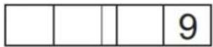
- When using numeric keys (0-9) and decimal keys, digit placement is determined as shown in the following example:
① Press "9". The setting window will show the following:
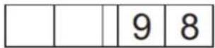
② Press "8". The setting window will show the following:
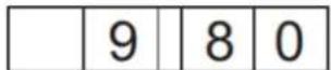
③ Press "0". The setting window will show the following:
④ Press "0". The setting window will show the following:
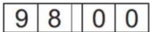
While the setting value flashes, press any numeric key to return to the first step.
- If the calorie value exceeds the range of 100 to 9999 kcal, after the ENTER key is pressed, the setting window will show the default value of 100 kcal, and the following reminder will appear for two seconds in the exercise feedback screen:

text_image
R A N G E 1 0 0 - 9 9 9 9- Press the CLEAR key at any time to clear settings to 0:00.
- The decimal < · > key does not operate during the time setting mode.
3. AGE
After establishing the workout goal, "ENTER AGE" appears on the exercise feedback screen. Use </> keys in the setting area or numeric keys (0-9) to select your age. Press the ENTER key to confirm the age setting and proceed to the weight setting.
Notes about the age setting appear below:
- The age setting range is from 10 to 99, with a default value of 35 years old.
- If the age setting range of 10 to 99 years is exceeded for two seconds, the following reminder appears on the exercise feedback screen:
| R | A | N | G | E | 1 | 0 | - | 9 | 9 |
- When </> keys in the setting area are pressed briefly, age values change by 1 year. When </> keys in the setting area are held down for one second or more, age values change by 1 year every 0.2 second.
- When using numeric keys (0-9), digit placement is determined as shown in the following example:
① Press "2". The setting window will show the following:
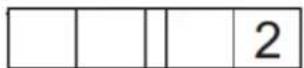
② Press "7". The setting window will show the following:
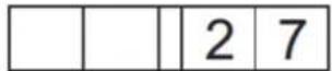
While the setting value flashes, press any numerical key to return to the first step.
- If no age is entered within six seconds, "PRESS ENTER" appears on the exercise feedback screen.
- Press the CLEAR key at any time to clear settings to 0.
- The decimal < · > key does not operate during the age setting mode.
4. WEIGHT
After establishing the age setting, the goal LED remains lit, and values in the setting screen flash. The dot matrix screen shows either lb. or kg; the default weight of 165 lb. or 75 kg appears; and "ENTER WEIGHT-KG" or "ENTER WEIGHT-LB" appears on the message screen, depending on the unit setting. Use <▲/▼> keys in the setting area or numeric keys (0-9) to select your weight. Press the ENTER key to confirm the weight setting and begin your workout.
Notes about the weight setting follow:
- The weight setting range is from 50 to 500 lb. (20 to 227 kg), with a default setting of 165 lb. (75 kg).
- If no value is entered for six seconds, "PRESS ENTER" appears on the exercise feedback screen for two seconds.
- When </> keys in the setting area are pressed briefly, weight values change by 1 lb. or 1 kg. When </> keys in the setting area are held down for one second or more, weight values change by 1 lb. or kg every 0.2 second.
- When using numeric keys (0-9), digit placement is determined as shown in the following example:
① Press "1". The setting window will show the following:
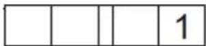
② Press "2". The setting window will show the following:
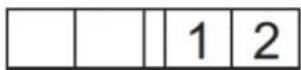
⑤ Press "5". The setting window will show the following:
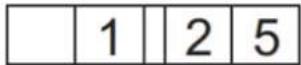
While the setting value flashes, press any numeric key to return to the first step.
- If the weight setting range of 50 to 500 lb. or 20 to 227 kg is exceeded, one of the following messages appears for two seconds.
| R | A | N | G | E | 5 | 0 | - | 5 | 0 | 0 |
| R | A | N | G | E | 2 | 0 | - | 2 | 2 | 7 |
- Press the CLEAR key at any time to clear settings to 0.
- The decimal <·> key does not operate during the age setting mode.
Follow prompts to begin your workout. Please refer to Workout Program Operation for specific information about workout programs.
OPERATION Workout Program Operation
The following explains features of the workout programs.
MANUAL
When the manual program is first activated, the workout illustration appears as follows.

text_image
Grid of white squares with a green square highlighted in red on the far right, likely indicating a selection or status.Manual operates much like QUICK START, except that in manual mode, you must select a workout goal. Simply press LEVEL <▲/▼> keys to control resistance.
RANDOM
This program provides a near infinite number of different workouts. Simply press the RANDOM key to view a different, randomly generated workout illustration.
Random programs are generated with the following conditions:
- Any single workout illustration can only appear once in 20 samples.
- Starting resistance can never be higher than level six.
- The difference between the levels of two adjacent columns cannot exceed six levels.
- The same level cannot recur for more than three columns.
- There are 65535 variations from which illustrations are randomly generated.
Push LEVEL <▲/▼> to make random workout illustrations expand upward or retract downward.
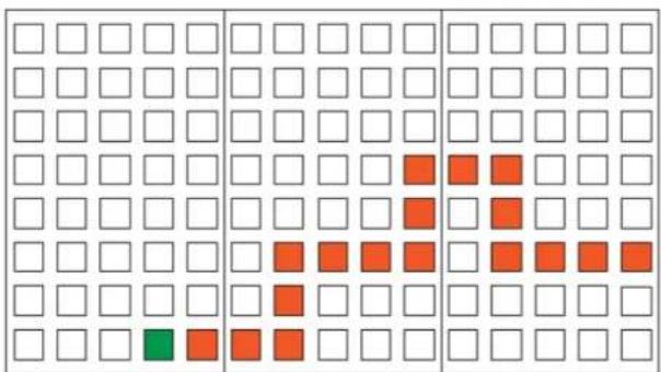
text_image
Grid pattern with white and red squares, one green square in bottom-left cellVARI-STRIDE
This workout program automatically adjusts stride length over 40 segments. Unlike other workout programs, the goal of the VARI-STRIDE program is always one of three time lengths.
After you press the VARI-STRIDE key, the TIME LED will light up. Follow prompts on the display to enter your age and weight values. The message screen will then prompt you to select one of three workout time lengths.
| 1 | - | 2 | 0 | 2 | - | 3 | 3 | - | 4 | 0 |
4-20 is a 20-minute workout, each segment of which lasts 30 seconds.
4-30 is a 30-minute workout, each segment of which lasts 45 seconds.
4-40 is a 40-minute workout, each segment of which lasts 60 seconds.
At this time, the workout goal percentage complete and setting screens will not be lit. If you do not press any number key within six seconds, the following prompt will appear for two seconds on the message screen:
| P | R | E | S | S | 1 | 2 | O | R | 3 |
At this time, either press numerical keys (1, 2, 3) to select one of the three workout durations, or press the ENTER key to directly select the default 20-minute workout.
After establishing the workout duration, maximum stride length must be selected. Stride length range is 25 to 29 inches or 630 to 730 mm, depending on the units of measure activated in User Preference Settings. The default stride setting is either 25 inches (imperial units) or 630 mm (metric units).
In the setting window, the default stride setting (either 25 inches or 630 mm) will flash. The message screen will show one of the following messages, depending on the unit setting:
| M | A | X | S | T | R | I | D | E | - | M | M |
| M | A | X | S | T | R | I | D | E | - | I | N | CH |
If no keys are pressed within six seconds, the message screen will show the following message for two seconds:
| P | R | E | S | S | E | N | T | E | R |
Press the ENTER key to confirm your selection.
Notes:
- While you press < keys to select maximum stride length, the stride length value on the display will not flash.
- If you press STRIDE LENGTH ▲ keys while exercising, the maximum stride length, rather than the actual stride length, will change.
When activated via another workout program, the VARI-STRIDE program will operate slightly differently. On the message screen, the following message will appear for two minutes:
| V | A | R | I | - | S | T | R | I | D | E | 2 | 0 |
Each time the VARI-STRIDE key is pressed, the message screen information changes as follows:
| V | A | R | I | - | S | T | R | I | D | E | 3 | 0 |
| V | A | R | I | - | S | T | R | I | D | E | 4 | 0 |
| V | A | R | I | - | S | T | R | I | D | E | 2 | 0 |
The stride length of each of the 40 segments is listed below:
Metric: 450, 450, 450, 450, 500, 500, 500, 500, 540, 540, 540, 540, 590, 590, 590, 590, 630, 630, 630, 630, 500, 540, 570, 590, 610, 630, 500, 540, 540, 590, 590, 630, 630, 590, 590, 540, 540, 470, 470, 470 mm
Imperial: 17, 17, 17, 17, 19, 19, 19, 19, 21, 21, 21, 21, 23, 23, 23, 23, 25, 25, 25, 25, 19, 21, 22, 23, 24, 25, 19, 21, 21, 23, 23, 25, 25, 23, 23, 21, 21, 18, 18, 18 inch
The preset workout illustration appears as follows:

text_image
Grid pattern with red and white squares, possibly representing a binary or data matrix- The first row (bottom) represents stride lengths of 17, 18, 19 inches or 450, 470, 500 mm.
- The second row represents stride lengths of 20 and 21 inches or 520 and 540 Mm.
- The third row represents stride lengths of 22 and 23 inches or 570 and 590~mm .
- The fourth row represents stride lengths of 24 and 25 inches or 610 and 630~mm .
- The fifth row represents the stride length of 26 inches, 660 mm.
- The sixth row represents the stride length of 27 inches or 680 ~mm .
- The seventh row represents the stride length of 28 inches or 700 ~mm .
- The eighth row (top) represents the stride length of 29 inches or 730 mm.
Note that when the maximum stride length is changed, stride lengths of subsequent segments also change. For example, change the maximum stride length from 25 to 27 inches; the maximum stride length of each subsequent segment will increase by two units as well.
The VARI-STRIDE program incorporates changes designed to spice up the exercise routine. For instance, at the 22^nd segment, the display will beep once, and the following message will appear in the message window:
BEGIN REVERSE MODE
At this point, the exerciser should reverse directions. Likewise, at the 27^th segment, the display will beep once and another message will appear:
RESUME FORWARD MODE
At this point, the exerciser should change again, resuming forward motion.
CARDIO/WEIGHT LOSS
In these heart rate control programs, the resistance level and recommended steps per minute (SPM) will automatically change to keep the exerciser's pulse at the optimum rate for achieving his or her fitness goals. Target heart rates are calculated based on a standard "maximum" heart rate for the exerciser's age. The weight loss target heart rate is calculated at 65% of the maximum heart rate: (220-age)*65%. The cardio target heart rate is calculated at 80% of the maximum heart rate: (220-age)*80%.
After a heart rate control workout is activated, a heart illustration will appear on the dot matrix screen. The color of the heart illustration will alternate from green to red with the user's pulse.
Once the exerciser begins to pedal, a red dot and a green line will appear on the lower part of the screen. The red dot represents the recommended SPM; the green line represents actual SPM. Try to maintain an SPM even with the red dot. In the illustration below, 124 represents the target heart rate.
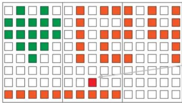
text_image
Grid pattern with colored squares (green, orange, red) and a diagonal line overlayThe red dot remains lit while the user exercises. The red dot extinguishes when no one exercises. (This dot represents the preset, or recommended, SPM.)
At the start of the heart rate program, resistance will start at level one. Recommended SPM is 50. If the actual SPM is 45 or lower for 25 seconds, "SPEED UP" will appear on the exercise feedback window.
The recommended SPM changes as follows.
- When actual heart rate is less than the target heart rate by more than three whole numbers for 36 seconds, the recommended SPM will increase by five SPM. Adjustments will not exceed the maximum, 65 SPM. Such adjustments occur once every 36 seconds.
- When actual heart rate is 1 or more whole numbers above the target heart rate for more than six seconds, SPM decreases by five SPM. Adjustments will not exceed the minimum, 40 SPM. Such adjustments occur once every six seconds.
The resistance level changes as follows:
- When actual heart rate is less than the target heart rate by more than three whole numbers for more than five seconds, resistance increases by one segment until the maximum, 80 segments (LEVEL 20), is obtained. Such adjustments occur once every five seconds.
- When actual heart rate exceeds the target heart rate by one or more for more than two seconds, resistance decreases by one segment. After making adjustments four times consecutively, if actual heart rate is not less than the target heart rate, no adjustments will occur for 15 seconds, after which downward adjustments will occur every two seconds. Adjustments will not fall below 12 segments (LEVEL 3). The adjustment process cycles in this pattern. Note: Each resistance level occupies four columns.
A telemetry heart rate transmitter must be worn during heart rate control programs. If no heart rate signal is received at the display for 30 seconds, the message □NO HEART RATE READING, PLEASE CHECK TRANSMITTER□ will appear, and resistance will not change automatically.
INTERVAL (INTV)
There are three interval programs: 1:1, 1:2, 2:2. Interval 1:1 indicates one segment of one minute in duration, followed by a second segment of one minute in duration. Interval 1:2 indicates one segment of one minute in duration, followed by a second segment of two minutes in duration. Interval 2:2 indicates one segment of two minutes in duration, followed by a second segment of two minutes in duration.
After the INTERVAL key is pressed and user information is entered into the display, the message window will appear as follows:
| 1 | - | 1. | 1 | 2 | - | 1. | 2 | 3 | - | 2. | 2 |
At this time, the workout goal percentage completed screen and the dot matrix screen will not be lit. If no keys are pressed within six seconds, the following prompt will appear for two seconds on the exercise feedback screen
| P | R | E | S | S | 1 | 2 | O | R | 3 |
At this time, press numerical keys 1, 2, or 3 to select one of the three interval programs or directly press the ENTER key to choose the first interval program, INTERVAL 1:1.
- INTERVAL 1:1→The rest segment resistance setting is level five; the work segment resistance setting is level eleven.
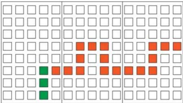
text_image
Grid pattern with colored squares (green, red, blue) and empty cells, likely representing a binary or data visualization.- INTERVAL 1:2→The rest segment resistance setting is level five; the work segment resistance setting is level 11.
text_image
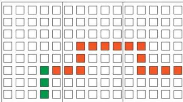
Grid pattern with colored squares (green, red, orange) indicating specific cells or cells in a 4x4 layout- INTERVAL 2:2→The rest segment resistance setting is level five; the work segment resistance setting is level 11.
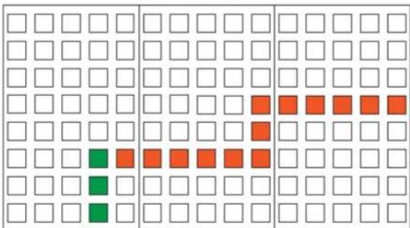
text_image
Grid pattern with colored squares (green, red, orange) indicating specific cells or cells in a 4x4 layoutRest and work segments are represented by dots. One dot represents one third of a minute (20 seconds).
Rest and work segments are represented by dots. One dot represents one third of a minute (20 seconds).
During an interval, resistance can be changed at any time. The resistance setting of the remaining part of the active segment will change. Already completed segments will remain unchanged. The first time that a rest segment transitions to a work segment, the following message will appear for two seconds on the exercise feedback screen:
W O R K S E G M E N T
Likewise, the first time that a work segment transitions to a rest segment, the display will beep once, and the following message will appear for two seconds:
R E S T S E G M E N T
At subsequent segment transitions, these messages will not appear on the display; the display will only beep once to indicate the change of a segment.
When entering the interval program from another program, the following message will appear for two seconds:
I N T E R V A L 1 - 1
Each time the INTERVAL key is pressed, interval programs appear in the following order:
I N T E R V A L 1 - 2 I N T E R V A L 2 - 2 I N T E R V A L 1 - 1
PLATEAU
When the plateau program is selected, the time LED lights up, and the time goal setting process begins.
Resistance levels in this time-based workout program gradually increase, level off,
Then gradually decrease. The first and last segments of this workout each occupy 20% of the workout. The middle segment occupies 60% of the workout.
line
| Value (%) | | :--- | | 20 | | 60 | | 20 |In the first segment, resistance increases from level one to level twelve. The middle segment retains level twelve resistance. In the last segment, resistance drops from level twelve to level one. The slope of the increase or decrease in resistance depends on the goal setting.
When WORKOUT LEVEL <▲/▼> keys are pressed, the dot matrix illustration will rise or fall correspondingly.
FAT BURN
This workout challenges exercisers with 20 stages of increasing physical intensity. The default startup stage is stage five. After selecting the FAT BURN workout, simply press LEVEL <▲/▼> keys to select a different stage. Then start exercising.
Within each stage, resistance levels occur in various patterns. Each resistance level lasts for one minute. The chart below shows stage numbers and their corresponding workout levels. Dots indicate a repetition of the pattern.
Stage 1: 1,2,.....
Stage 2: 1,2,3,.....
Stage 3: 1,2,3,4,4,3,2,1,...
Stage 4: 1.3,5,2,4,.....
Stage 5: 2,4,6,1,3,5,.....
Stage 6: 1,4,7,2,3,5,6,...
Stage 7: 1,2,3,4,8,7,6,5,.....
Stage 8: 2,4,6,8,3,5,7,9,.....
Stage 9: 3,4,5,6,7,8,9,10,.....
Stage 10: 4,6,8,10,5,7,9,11,.....
Stage 11: 5,6,12,7,8,11,9,10,.....
Stage 12: 6,7,8,13,9,10,11,12,.....
Stage 13: 7,9,11,8,10,12,13,14,.....
Stage 14: 8,9,10,10,11,12,12,13,13,14,14,15,.....
Stage 15: 9,10,16,15,14,13,12,11,.....
Stage 16: 10,13,15,17,17,16,15,14,12,11,...
Stage 17: 11,12,13,14,18,17,16,15,.....
Stage 18: 12,19,13,18,14,17,16,15,.....
Stage 19: 13,20,14,19,15,18,16,17,
Stage 20: 14,20,15,20,16,20,17,20,18,20,19,20,.....
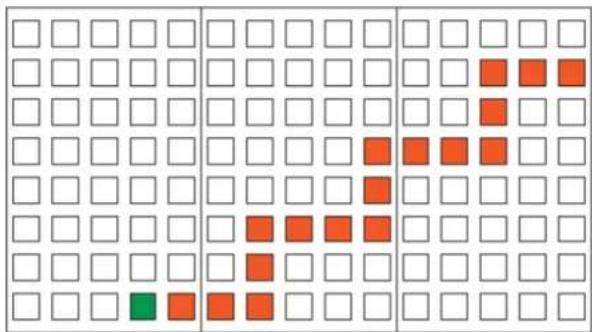
Each time one stage advances to a higher stage, the message window will show the new stage number.
Example: STAGE 9→STAGE 10
| S | T | A | G | E | 1 | 0 |
The workout illustration on the dot matrix screen will appear as follows.
Example: Stage 10
text_image
Grid pattern with white squares, red squares, and one green square in the bottom-left cellThe lowest resistance level of each stage becomes the reference resistance level, from which the progression is built.
CUSTOM
The CUSTOM heart rate control program allows you to set your target heart rate. The CUSTOM heart rate setting range is 84 to 199 beats per minute, with a default setting of 120 beats per minute.
Upon entering this workout, the goal LED will light, the default target heart rate of 120 will flash, and "ENTER TARGET HR" will appear on the message screen.
Use </> keys or numeric keys (0-9) to increase or decrease the target heart rate. Beat per minute values change by one beat each time </> keys are pressed. To change values faster, hold these keys down for more than one second. Values will change by one beat per minute every 0.2 second.
Press the ENTER key to confirm your setting. If you do not press the ENTER key within six seconds, the message window will show "PRESS ENTER". If your entry exceeds the range of 84 to 199 beats per minute, the default target of 120 beats per minute remains on screen, and the following prompt appears for two seconds on the message screen:
| R | A | N | G | E | 8 | 4 | - | 1 | 9 | 9 |
Other notes:
- Press the CLEAR key to return to the default (120 beats per minute).
- The <·> decimal key is not effective in this setting.
Follow prompts to establish your speed and to begin your workout.
OPERATION Switching Workouts
A different workout program can be activated from any workout program. The original workout goal will remain in effect, and workout feedback will continue to accrue. For example, in a random workout with distance as the goal, if you press the INTERVAL key, distance will remain the goal and continue to accrue.
Workout goals can be adjusted after they are established. To do so, press the original WORKOUT GOAL key, adjust the goal setting with arrow or numeric keys, and press the ENTER key to confirm the setting. The new workout goal takes effect under certain conditions, as follows:
- If the new value is lower than the actual workout value, the original goal setting value remains in effect.
- If the new value is lower than the goal's lowest range value, the lowest range value becomes the setting value. But if the lowest range value is lower than the actual value (shown in the workout feedback display), the original setting remains in effect.
- If the new value is higher than the actual workout value and lower than the original setting, the setting value decreases.
- If the new value is higher than the actual workout value and higher than the original setting, the setting value increases.
If distance or calories is the workout goal, increasing or decreasing the goal setting will not result in a change in the dot matrix illustration.
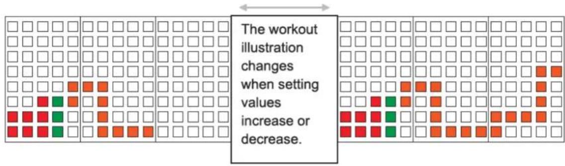
When time is the workout goal, increasing or decreasing the goal setting results in a change to the dot matrix illustration as follows:
- When the present illustration occupies less than 12 columns, increasing the setting value results in an increase in the number of columns.
- When the present illustration shows more than 12 columns, decreasing the goal setting to more than 12 columns results in no change.
- The illustration below shows the result of increasing (right) or decreasing (left) the setting.
text_image
The workout illustration changes when setting values increase or decrease.If setting values are not changed within 12 seconds, or the ENTER key is not pressed, no change is made.
OPERATION Cool Down
-
When you reach your workout goal (time, distance, calories), or press < STOP/HOLD TO RESET > key to stop the workout and enter COOL DOWN. The data screen will display "COOL DOWN". The COOL DOWN will end when 2 minute timer is up.
-
Once "COOL DOWN" is completed, the data screen will display "ACCU DATA", including user's workout time, distance, calorie, average heart rate and energy generated. Press < STOP/HOLD TO RESET > key at this time to return to BANNER/SELECT PROGRAM screen.
OPERATION Power Saving and Power Down
This product is designed to save power when not in use. If no one exercises on the product or presses any key for 15 seconds, lines on the message screen will flash, appearing as follows:
| - | - | - | - |
If someone exercises or presses a key, the workout will resume. If, for one minute and twenty seconds, no one exercises on the product and no one presses any key, the product will turn off; all LEDs on the display will extinguish. This product can also be turned off manually. Simply press the FAN key for three seconds to turn off unit power.
A collection of notes about various aspects of this product follows.
Display Shut Off
To save energy, the display on this self-powered product automatically turns off when no keys are pressed and no one exercises on the product for one minute and twenty seconds. The display can also be turned off manually. To manually turn off the display, while no one exercises on the product, press and hold the FAN key for three seconds. The display LEDs will extinguish.
Fan Operation
The fan operates only when pedal rotation exceeds 25 SPM, unless an adapter (33 VDC 1.9A 62.7W) is plugged into the connector at the front base of the product.
Battery Charge
On this self-powered product, the battery recharges when someone pedals at over 30 RPM for three seconds or more. An exterior adapter (33 VDC 1.9A 62.7W) can also be used to charge the battery. When an exterior adapter is in use, the display will not automatically turn off, and fan operation will not be affected by SPM.
Distance and Time Logging
Distance and time are recorded one minute after the unit enters the battery saving mode. If the unit is shut off manually, distance and time are recorded immediately.
USB Port
The USB port in this product can be used for providing 5V 500mA of power for devices such as USB memory sticks, iPod ^® devices, cameras, mobile phones, and other items. (Third generation or newer iPod devices support power charging via USB ports.)
Note: iPod is a trademark of Apple Inc., registered in the US and other countries.
"Made for iPod" means that an electronic accessory has been designed to connect specifically to iPod and has been certified by the developer to meet Apple performance standards. Apple is not responsible for the operation of this device or its compliance with safety and regulatory standards.
OPERATION
User Preferences and Part Versions
Units of measure shown on this product's display can be modified. Total operating distance and hours of use can be viewed and deleted. Display and drive board version numbers can also be viewed.
To accomplish any of these tasks, at the startup banner screen (as "E872" appears on the screen), hold the ENTER key for three seconds. User preference mode will be activated.
UNITS
The display will show "UNIT-MPH" or "UNIT-KPH" depending on the original speed unit setting. Press < keys to toggle between the two settings. When your preference appears, press the ENTER key to make your selection and proceed to view total distance.
Notes about unit settings:
- If no keys are pressed within six seconds, the message screen will show the message "PRESS UP/DN TO SELECT UNIT OR ENTER".
- To exit the user preference selection mode, press the STOP key. The startup banner screen will appear. (The stop key can be used to exit the user preference mode at any time within this mode.)
TOTAL DISTANCE
According to the speed unit setting, total distance will appear as either "DIST XXXXXX MILE" or "DIST XXXXXX KM", where XXXXXX represents a number. Press the ENTER key to view total time.
Notes about operating the product while total distance is visible:
- If no keys are pressed within six seconds, "PRESS UP/DN TO SELECT UNIT OR ENTER" will appear on the message screen.
- To clear total distance memory, press the CLEAR key for three seconds. "DIST-0 KM" - or "DIST-0 MILE" will appear, indicating the distance memory has been erased.
- To exit the user preference mode, press the STOP key. The startup banner screen will appear.
TOTAL TIME
Total time of use will appear as "TIME XXXXXX HOUR", where XXXXXX represents a number. Press the ENTER key to view the display program version.
Notes about operating the product while total time is visible:
- If no keys are pressed within six seconds, "PRESS ENTER" will appear on the message screen for two seconds.
- To erase time memory, press the CLEAR key for three seconds. "TIME -0 HOUR" will appear, indicating that time memory has been erased.
- To exit the user preference mode, press the STOP key. The startup banner screen will appear.
DISPLAY PROGRAM VERSION
The display program version will appear as "CTL XE872H-1A", for example. In this example, the X represents the multiple language setting. Press the ENTER key to view the drive board program version.
Notes about operating this product while the display program version is visible:
- If no keys are pressed within six seconds, "PRESS ENTER" will appear for two seconds.
- To exit the user preference mode, press the STOP key. The startup banner screen will appear.
DRIVE BOARD PROGRAM VERSION
The drive board program version will appear as "DRV E872-1A", for example. Press the ENTER key to exit the user preference mode and return to the startup banner screen.
7. ABOUT HEART RATE DETECTION AND PRESENTATION
Heart rate detection functions are selected when the distributor orders from the SportsArt factory. Not every product comes equipped with all types of heart rate detection. If your product is equipped with these functions, please note the following information.
HEART RATE Telemetry
The word "telemetry" heart rate refers to the detection of the heart rate, usually via a strap worn on the exerciser's chest and transmitted over the air for reception by a receiver built into the product. The following explains conditions that influence the performance of the telemetry heart rate function in all products.
- The telemetry heart rate transmitter emits a wireless 5kHz signal that is harmless to the human body. Inside the transmitter is a 3V battery (CR2032). If the battery charge is too low, either the reception distance shortens or there will be no reception whatsoever.
- Secure the telemetry heart rate transmitter on your chest so it is neither too tight nor too loose. Moisten the skin for better contact.
- The telemetry heart rate receiver accepts a 5kHz wireless signal, but because the signal varies from 20Hz to 20KHz, it is susceptible to environmental interference. Stereos, TVs, other electronic products, the vibration between the unit and the floor, and other factors may interfere with telemetry heart rate signal reception. For best results, install the product in a location free from interfering items.
- Spraced fitness product the partly at least 39 inches (100 rate value from an exerciser on one product appear on another product.
- Heart rate values are for comparison only. Do not use them for medical treatment or other purposes.
HEART RATE Contact
It is easy to use the contact heart rate mechanism. Simply put both hands on the silver contact plates (one per side) and hold them there continuously. As soon as your pulse is received and calculated, the heart rate will automatically appear on the display.
Please note that some people have very weak heart beats. This makes heart rate detection difficult. Under such circumstances, the contact heart rate mechanism may not detect heart rate.
Please note the following:
- For best results, continuously hold the contact heart rate plates.
- It is difficult to detect the heart rate of people who have low systolic blood pressure.
- It is difficult to detect the heart rate of people who have dry, course palms. Keeping palms smooth and damp improves heart rate detection.
NOTE: TO PREVENT STATIC ELECTICAL SHOCKS
In dry areas in particular, static electricity can interfere with unit operation and shock people. Suggestion: Before touching metal parts of the product, first touch a material with electrically isolative properties, such as the plastic on the handlebars.
CAUTION: Heart rate detection and signal transmission devices have been known to interfere with the operation of pacemakers, possibly endangering human life. If you have a pacemaker, the use of such devices must be undertaken at your own risk. We recommend that you conduct an exercise test under your doctor's supervision. The purpose of the test would be to ensure the safety and reliability of the simultaneous use of the pacemaker and such devices.
8. GUIDELINES FOR EXERCISE
HOW HARD SHOULD I EXERCISE?
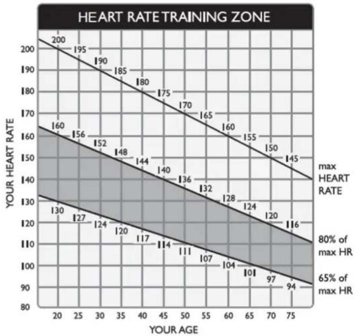
Studies show that to achieve the benefits of aerobic exercise, it is necessary to work within your training zone. Your training zone depends on your age and level of fitness.
The darkened area in the chart to the right indicates the recommended heart rate training zone. These figures are calculated by taking 220 minus your age, and calculating 80% for your maximum and 65% for the minimum heart rate for aerobic exercise.
CAUTION:
line
| YOUR AGE | YOUR HEART RATE | | --------- | --------------- | | 20 | 200 | | 25 | 195 | | 30 | 190 | | 35 | 185 | | 40 | 180 | | 45 | 175 | | 50 | 170 | | 55 | 165 | | 60 | 160 | | 65 | 155 | | 70 | 150 | | 75 | 145 | | 20 | 160 | | 25 | 156 | | 30 | 152 | | 35 | 148 | | 40 | 144 | | 45 | 140 | | 50 | 136 | | 55 | 132 | | 60 | 128 | | 65 | 124 | | 70 | 120 | | 75 | 116 | | 20 | 130 | | 25 | 127 | | 30 | 124 | | 35 | 120 | | 40 | 117 | | 45 | 114 | | 50 | 111 | | 55 | 107 | | 60 | 104 | | 65 | 101 | | 70 | 97 | | 75 | 94 |Heart Rate training zones are approximations. Always check with your physician to understand what heart rate goal would be appropriate for you.
HOW LONG SHOULD I EXERCISE?
The duration of your exercise session depends on your fitness level. In general, it is recommended that you maintain your heart rate in the training zone for at least 15 to 20 minutes to realize an aerobic benefit. Beginners should always start slowly and gradually increase the duration of their workouts.. As your fitness level improves, you will be able to maintain your heart rate in the training zone for longer periods of time.
When beginning your workout, use the first several minutes to warm up, then slowly increase your workload to bring your heart rate into your specific training zone. At the end of your workout, gradually decease your workload, then exercise lightly to cool down.
HOW OFTEN SHOULD I EXERCISE?
Research indicates that to achieve the greatest benefits, exercise should be performed three to five times per week. It is important to allow sufficient time, at least 24 hours, for your body to recover after exercise.
9. MAINTENANCE
MAINTENANCE Stride Worm Gear Lubrication
It is recommended that you inspect worm gear operation every six months. It should operate smoothly, without rattling or scraping sounds. The worm gear itself should feel moist with grease. Follow instructions below to lubricate the worm gear, as necessary.
As the message window appears, simultaneously press and hold ENTER and CALORIES keys for three seconds.
SELECT PROGRAM OR QUICKSTART
After entering the lubrication mode, the stride motors will automatically adjust to expose the zerk fitting. The following message will appear on the setting screen:

Please follow steps below to physically apply lubricant.
(a) Remove the cap that covers the lubrication hole.
(b) Use an automobile grease gun with red lithium grease. Apply the grease to the zerk fitting on the product.
(c) After lubricating the product, remove the grease gun.
(d) Insert the cap back into place.
natural_image
Technical line drawing of a pipe connection with a hook and directional arrow (no text or symbols)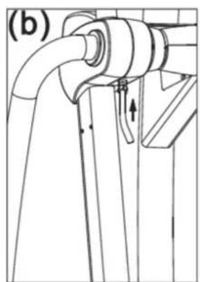
natural_image
Technical line drawing of a mechanical component with pipes and a valve (no text or symbols)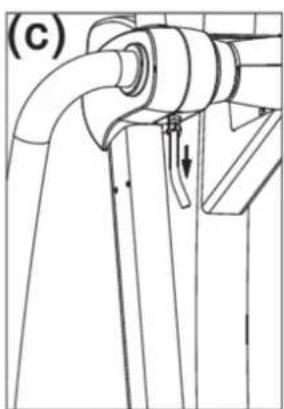
natural_image
Technical line drawing of a mechanical component with no visible text or symbols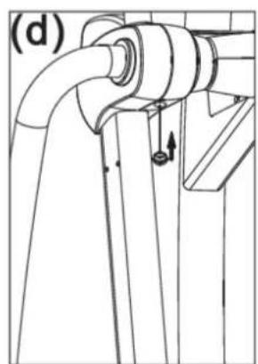
natural_image
Technical line drawing of a pipe joint with a hook and directional arrow (no text or symbols)MAINTENANCE Stride Worm Gear Lubrication, Continued
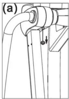
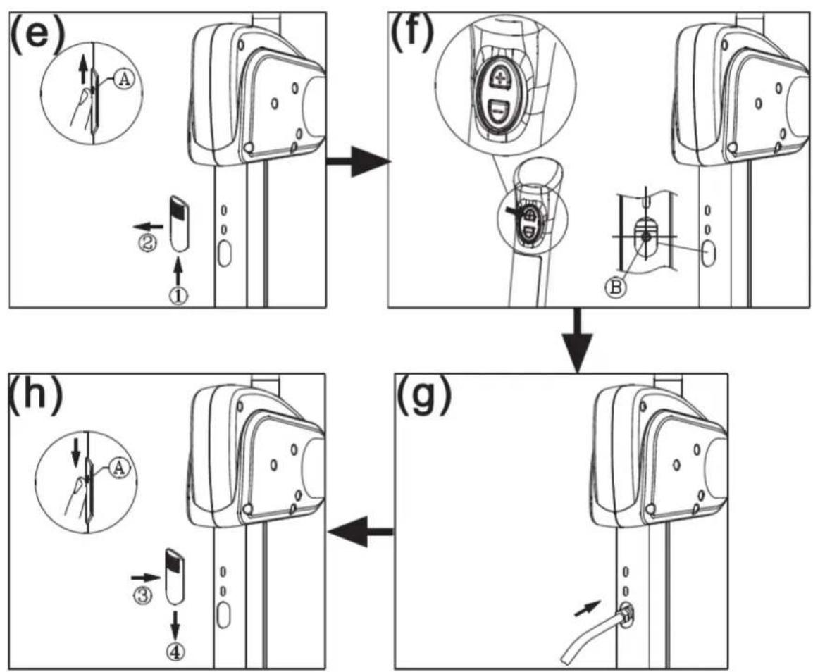
(e) Push in at point A, and slide upward to remove the lubrication hole cover from the product.
(f) Press the stride up key to adjust the stride to its longest point. Note the grease fitting at area B.
(g) Use an automobile grease gun with red lithium grease. Apply the grease to the zerk fitting on the product.
(h) Put the cover back into place, pushing inward at step 3, then downward at step 4, as shown below. (Note that point A provides the best contact surface on the lubrication hole cover.)
NO STRIDE ADJUST UNDER 25 SPM
Indication: Under 25 SPM, the stride adjustment mechanism will not operate. The following message will appear:
NO STRIDE ADJUST UNDER 25 SPM
Exercise at over 25 SPM to operate the stride adjustment mechanism.
SERVICE BATTERY
If battery voltage is low, the following message will appear for two seconds.
| S | E | R | V | I | C | E | B | A | T | T | E | R | Y |
ERR7
This error message indicates a stride motor calibration issue. It appears under the following scenarios.
When the unit powers up, it detects the voltage of the stride motor variable resistor. If the voltage exceeds the lower limit (<0.5V) or the upper limit (>4.5V), ERR7 appears.
When the issue is associated with the right side, the following message appears:
| E | R | R | 7 | I | N | C | L | I | N | E | - | R |
When the issue is associated with the left side, the following message appears:
| E | R | R | 7 | I | N | C | L | I | N | E | - | L |
When the issue is associated with both sides, the following message appears:
| E | R | R | 7 | I | N | C | L | I | N | E | - | R | / | L |
MAINTENANCE Cleaning
Please clean glide rails once a day as follows:
(a) Use a clean, lint-free cloth to wipe dirt and dust off the glide rails.
(b) Operate the product to make sure glide rails operate smoothly.
(c) Repeat actions (a) and (b) two or three times to ensure smooth action.
text_image
Technical line drawing of an stationary exercise machine with labeled control panel and directional arrows indicating motion.10. MAINTENANCE
Maintenance Schedule
| (E872) Maintenance Schedule | |||||||
| Area | Daily | Weekly | Monthly | Quarterly | Yearly | Notes | |
| 1 | Exterior | ● | Clean. | ||||
| 2 | Screws | ● | Inspect and secure loose parts. | ||||
| 3 | Glide rail | ● | Wipe away dirt and debris. | ||||
| 4 | Rollers | ● | Apply silicone lubricant, move, and clean. | ||||
| 5 | Stride motor | ● | Apply grease. | ||||
| 6 | Cushion | ● | Apply SportsArt 66A lubricant | ||||

text_image
Technical diagram of a stationary exercise machine with labeled parts including control panel, gear shift, and mechanical components.Maintenance Task List (Elliptical Trainers)
Like cars, fitness products require maintenance. Regular maintenance extends product life, and failure to maintain products can void the manufacturer's warranty. Copy the maintenance log sheet, and record maintenance work for each fitness product.
Daily tasks
- Use a clean, lint-free towel, dampened with a mixture of Simple Green ^® all-purpose cleaner and water, to thoroughly clean the product exterior.
- Inspect parts for looseness, and secure all loose screws. Make sure that the product is safe for operation. If safety issues arise, place an "Out of Order" sign on the product, and call for service.
- Wipe dirt and debris off the glide rails. Use a clean, lint-free towel, dampened with a mixture of Simple Green ^® all-purpose cleaner and water.
Weekly tasks
- Clean rollers. Use a clean, lint-free towel, dampened with a mixture of Simple Green® all-purpose cleaner and water. Apply a small amount of silicone lubricant onto the rollers.
Yearly tasks
-
Apply grease to the stride mechanism.
-
Apply SportsArt 66A lubricant to the cushion.
Caution
- Please follow standard safety precautions when working on this product.
- Electronic components can carry an electrical charge even after the product has been turned off. For safety, turn off unit power. Wait five minutes to allow capacitors to discharge. Then disconnect the power cord from the wall socket (if applicable). Only after such steps have been completed should covers be removed and electronic components accessed.
- Do NOT use cleaners with alcohol, ammonia, or other damaging chemicals. The use of such chemicals can damage the product and void the warranty. Never spray or pour any liquid directly onto the product. Doing so can damage electronic components and void the warranty.
- This product has moving parts that can be hazardous. Exercise caution when maintaining, operating, or moving this product.
Maintenance One-Year Maintenance Log
Facility :
Supervisor:
Product Model Number :
Serial Number:
Start Date:
End Date:
| Daily Tasks | Weeks 1-7 | Weeks 8-14 | Weeks 15-21 | Weeks 22-28 | |||||||||||||||||||
| Completed | |||||||||||||||||||||||
| Daily Tasks | Weeks 29-35 Weeks 36-42 Weeks 43-49 | Weeks 50-52 | |||||||||||||||||||||||||
| Completed | |||||||||||||||||||||||||||
| Weekly Tasks | Weeks 1-7 Weeks 8-14 Weeks 15-21 | Weeks 22-28 | ||||||||||||||||||||||||||
| Completed | ||||||||||||||||||||||||||||
| Weekly Tasks | Weeks 29-35 Weeks 36-42 Weeks 43-49 | Weeks 50-52 | |||||||||||||||||||||||||
| Completed | |||||||||||||||||||||||||||
| Monthly Tasks | 1 | 2 | 3 | 4 | 5 | 6 | 7 | 8 | 9 | 10 | 11 | 12 |
| Completed |
| Quarterly Tasks | Quarter 1 Quarter | 2 Quarter 3 | Quarter 4 | |
| Completed |
| Yearly Tasks | Year 1 |
| Completed |
Notes:
11. BLOCK DIAGRAM
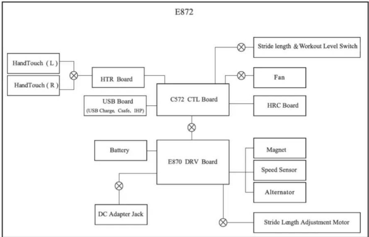
flowchart
graph TD
    A["HandTouch (L)"] --> B["×"]
    C["HandTouch (R)"] --> B
    B --> D["HTR Board"]
    D --> E["C572 CTL Board"]
    E --> F["Stride length & Workout Level Switch"]
    E --> G["Fan"]
    E --> H["HRC Board"]
    I["USB Board\n(USB Charge, Csafe, IHP)"] --> E
    J["Battery"] --> K["E870 DRV Board"]
    L["DC Adapter Jack"] --> K
    K --> M["Magnet"]
    K --> N["Speed Sensor"]
    K --> O["Alternator"]
    K --> P["Stride Length Adjustment Motor"]
Your Authorized SPORTS ART Distributor