
AXC26S - Car hands-free kit Axton - Free user manual and instructions
Find the device manual for free AXC26S Axton in PDF.


| Product Type | 2-Way Component Speaker System |
| Model | AXC26S (equivalent to AC26) |
| Woofer Size | 6.5 inches (16.5 cm) Euro-DIN frame |
| Tweeter Size | 52 mm outer diameter, swiveling design |
| Peak Power Handling | 160 W |
| Continuous Power Handling (RMS) | 120 W |
| Impedance | 4 Ohms |
| Sensitivity (1W/1m) | 91 dB |
| Frequency Response (-3dB) | 60 Hz – 25 kHz |
| Crossover Frequency | 3500 Hz |
| Crossover Slope - Lowpass (Mid/Woofer) | 6 dB/octave or 12 dB/octave (switchable) |
| Crossover Slope - Highpass (Tweeter) | 12 dB/octave |
| Tweeter Attenuation Settings | 0 dB, -3 dB, -6 dB |
| Tweeter Polarity Switch | 0° or 180° |
| Woofer Mounting Depth | 66 mm |
| Woofer Mounting Diameter | 144 mm |
| Tweeter Flush Mount Hole Diameter | 52 mm |
| Tweeter Mounting Height (flat surface) | 31 mm |
| Included Accessories | 2 mid/woofers, 2 grilles, 2 tweeters, 2 crossovers, wiring hardware, mounting hardware, manual |
| Warranty | 2 years from retail purchase |
| Recommended Cable Cross-Section | Minimum 2.5 mm² |
| Water Resistance | Cone and surround 100% waterproof; avoid direct water exposure |
Frequently Asked Questions - AXC26S Axton
User questions about AXC26S Axton
0 question about this device. Answer the ones you know or ask your own.
Ask a new question about this device
Download the instructions for your Car hands-free kit in PDF format for free! Find your manual AXC26S - Axton and take your electronic device back in hand. On this page are published all the documents necessary for the use of your device. AXC26S by Axton.
USER MANUAL AXC26S Axton
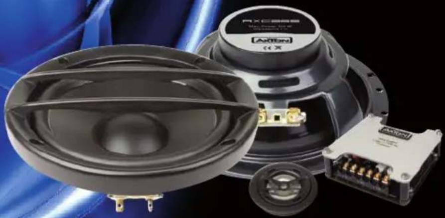
COMPONENT SYSTEMS
Thank you and congratulations on your purchase of this AXTON AC 2-way component system. This loudspeaker system uses very high quality parts and components only. The careful development of the speaker units and the crossovers becomes obvious, when the system is installed and playback starts. As with all high-quality car audio components, professional installation is highly recommended. If you plan on installing this component system by yourself, please read the following installation guide carefully, before you attempt the installation. You should retain this manual, the packing and the purchasing receipt for future reference. For any further information about mounting, connecting or adjusting this speaker system, please contact your authorized AXTON dealer.
UNPACKING THE SYSTEM
Carefully remove the loudspeakers, crossovers and the accessories from the giftbox and check whether all parts are in good undamaged condition, and match with the set contents listed below:
■ 2 mid/woofers
■ 2 grilles
■ 2 AT25 tweeters
■ 2 crossovers
■ 1 set of wiring hardware for tweeter and mid/woofer
■ 1 set of tweeter & mid/woofer mounting hardware
■ 1 instruction manual with warranty card
Please contact your authorized AXTON dealer if the content of this set is incomplete or parts of it show signs of transport damage.
BEFORE YOU START
The first step is to choose the most suitable or best sounding location for the speakers to be installed. Keep in mind that the best looking spot might not be the one that gives you best sound. The factory OEM speaker cutouts usually provide space and a stable platform for fast and convenient mounting of new mid/woofer units. To use the OEM speaker cutouts is highly advantageous in most cases and it will also prevent you from having to cut new holes. For the tweeter mounting, some extra care to find the best spots will usually pay back in form of improved front staging or/and better resolution.
MOUNTING THE MID/WOOFERS
Remove the factory grilles of the door - or if necessary - the complete door panels. The 13 / 16.5 cm EURO-DIN frame mid/woofer units provide bolt and screw holes to fit a great variety of OEM standard patterns, making them ideal for a direct replacement of factory installed speakers in European or Asian cars.
■ Remove the factory installed mid/woofers or fullrange speakers. Before you attempt to install the new AXTON mid/woofers, you must check the available installation depth of the left and right front door. To do this, slide down both windows and hold the AXTON mid/woofers in place to reassure the available installation depth does suffice. This test is important, failure to do this may let you end up with an impaired window function!
■ Look out for a good location to mount the crossovers. Consider that the x-overs should remain accessible for adjustments after the installation of the speakers is completed. Potential places to mount your x-overs are under the dashboard, inside the doors, a.s.o.
■ Connect the corresponding speaker wires to the blade connector terminals of the mid / woofer units. Route these wires to the location, that was chosen to install the crossovers later on.
- Check that there are no gaps between the speakers and the mounting surface in the doors. Note that some (newer) cars will require the use of car-specific mounting adapters made of pastic material. Without them, the Euro-DIN mid/woofers will not fit to the OEM cutout, or the available installation depth will not be sufficient. Such adapters are usually available from your authorized AXTON dealer.
■ The cone and surround material of the mid/woofers is 100% water proof. However a direct exposure of the mid/woofer to water inside the doors should be avoided. In most cases, protection foils are pre-installed to protect the OEM full-range speaker. Do not rip this foil out of the doors, it is there for a purpose!
- Fix the mid/woofer to the speaker mounting hole using the provided screws. If the mid/woofers are directly screwed onto the sheetmetal of the door, use the metal clips included with the mounting hardware. You can now reinstall the factory plastic grilles, but make sure the surrounds of the mid/woofers do not come in touch with plastic parts standing off on the backside of the grilles.
In case you have chosen a new location for your mid/woofers (other than factory cut-out), use the speaker protection grilles. Just mount them on top of the mid/woofers.
TWEETER MOUNTING LOCATION
The tweeter positioning does exhibit a direct and profound influence on the front staging of your component system. Depending on the chosen location where the tweeters will be installed, different loudness levels in the high-frequency region will result. The tweeter level can be adjusted on the pc board of the x-over, to compensate for different mounting locations.
■ To determine the best tweeter location, it may be necessary to carry out short listening tests with the tweeter mounted to different locations inside the vehicle. For this, double sided tape can be used.
■ Set all tone controls, i.e. pre-EQ, treble / bass and loudness functions of your headunit to the neutral position first, before you attempt any listening test of the speakers installed to your car.
The influence of the tweeter mounting location on the front staging remains – and care must be taken to achieve a good compromise between unobtrusive mounting and good sound quality.
Examples of different tweeter mounting locations, and the results that are most frequently obtained, are explained below:
1 A-Pillar
Best option concerning the depth of image and overall sound balance of the component system. Not that easy to get right, i.e. high mounting efforts.
2 Dash Board
Sometimes aggressive sound and overly brilliant treble reproduction caused by the horn loading effects of the front window. Setting tweeter ATT switch to -6 dB may help.
3 Window Triangle
Bright sound combined with a high soundstage, sometimes sounding a bit “nervous” with some side biasing too.
4 On the upper end of the door panel
Balanced sound with good staging qualities
5 Right on top of the mid/woofer
Good staging, but often “dull” sound, especially with a person sitting on the passenger's seat.
Note: A “on-axis” installation (with tweeters directly pointing at the listener) is not required, neither recommended.
Tweeters directly aiming at the listener's ears are usually responsible for the unwanted "side-biasing" effect, where the sound seems to originate from the drivers, instead of floating on top of the dashboard.
The tweeters come with swiveling function, play around with it – but don't overdo the job!
TWEETER INSTALLATION
There are two ways to install the AT25 tweeters: Angled surface or fully recessed mounting.
Flat Surface Mounting
The tweeter system consists of three parts: The main tweeter unit, the backside of the housing adapter and the front ring.
■ Mark the location where you are going to mount the tweeters. Drill three holes on each side, one main hole with a bigger diameter for the wire and two small pilot holes for the two screws fixing the tweeter housing to the mounting surface.
■ Mount the adapter cup with two flathead screws.
■ Feed the wire through the hole and connect it to the wire extension that goes to the crossover. Align the front ring over the the tweeter main housing, push it down and turn the ring clockwise to fix it in place (bayonet design).
Flush Mounting
After choosing the best mounting location, make sure there is at least 25 mm of clearance behind the mounting surface (for the tweeter cross-spring!), before you start to mark or cut anything!
Cut a hole with exactly 52 mm diameter into the mounting surface using a power drill and a circle cutter tool.
Secure the flush mount tweeter adapter in the cutout with the metal cross blade and the two machine screws provided in the mounting accessory kit. Push the main tweeter down into the rear cup with the frontring on top, turn clockwise to lock it. Feed the wire through the center hole of the cup and attach the wire to the extension cable that goes to the crossover.
CROSSOVER WIRING & MOUNTING
The crossover can be mounted in almost any location inside the vehicle. Recommended places are: Inside the door, under the carpet in front of the door angles, under the dashboard a.s.o. Just make sure not to install the crossover units, where they may be exposed to dirt or excessive moisture / water.
Connect the tweeter wires, the wires from the mid/woofers and the main wires coming from the amplifier to the crossover. Maintain polarities all the way – double check for correct connection. It is very important to make sure that all the connections are electrically in phase, which means positive wire (+ or red) is connected to positive terminal, and negative wire (- or black) is connected to the negative terminal.
Reverse polarity connections, i.e. when a mid/woofer is concerned, will cause a very low bass output and a messed up front staging.
If longer distances from the amplifier to the crossovers have to be overcome, use good quality speaker cables with a minimum cross section of 2.5mm2 . Failure to do so will affect sound quality in a negative way.
X-OVER ADJUSTMENTS
All AC AXTON component set crossovers come with three adjustment options that allow you to tailor the sound by setting slide switches on the pc board inside the housing, to compensate for different mounting locations of the speaker units, as follows:
■ Switchable lowpass filter slope for the mid/woofer
■ Switchable tweeter polarity
■ Switchable tweeter attenuation
Attention:
The first two adjustment options - lowpass slope and tweeter polarity - play hand in hand and must therefore be tested and adjusted together, to achieve the desired sonic results.
Lowpass Slope Setting for Mid/Woofer (Switch „6dB / 12dB“)
The most important design aspect of a component speaker system is the crossover design. The object in choosing a crossover slope and crossover frequency is not only to maintain power handling as per the drivers used, but also to assure that there is a smooth frequency response transition between them, even when the drivers are not mounted on the same axis or close to each other. For these reasons the CAC x-over combines a 12dB slope on the tweeter highpass with a selectable 12dB or 6dB lowpass for the mid/woofer. Now why is the lowpass crossover selectable between 6dB and 12dB? The reason for this is phasing! When the tweeter is mounted within 20cm of the mid woofer and both speakers are located on the same virtual plane, these drivers will remain in phase with each other. This means that the switch for the crossover slope should be set to 12dB.
However, when the tweeter is separated from the midrange beyond 20cm or is located on a separate plane, the crossover slope in most cases should be set to 6dB.
This will help to maintain in-phase performance at the x-over point, creating a smoother blend between the tweeter and the mid/woofer. This may also improve the sweet spot of the drivers, making it harder to distinguish that the drivers are located in separate areas. To switch the mid/woofer phase, locate the switch marked „-6dB – 12dB“ on the crossover pc board and choose the 12dB or 6dB setting accordingly.
Tweeter Polarity Setting (Switch "0° / 180°")
After setting the lowpass slope to either 6dB or 12dB, the tweeter polarity switch on both crossovers must also be switched to either 0° or 180°, with a short listening test that determines the better result. Either the 0° or 180° tweeter polarity will give you in-phase response, that manifests in form of better midrange clarity and precise front staging. Drivers playing out of phase will sound dull and uninvolving in the mid/range.
Attention:
Both the lowpass slope and the tweeter polarity switches must always be set to an identical position on both x-overs!
Tweeter Attenuation Setting (Switch "0dB / -3dB / -6dB")
The tweeter attenuation circuit is to attenuate the output level of the tweeter, compensating the treble energy for various tweeter mounting locations or personal preferences, respectively. This circuit has three positions to choose from, 0dB/-3dB/-6dB. By selecting the -3dB or -6dB position of the switch, you lower the output level of the tweeter. This allows you to tailor the volume level of the tweeters for best overall balance of the sound. To adjust the tweeter level, simply shift the switch to the desired position.
As a general rule of thumb, the -6dB position is best for tweeters that are mounted very close to the listener's head, or for tweeters mounted on top of the dash-board and in the window triangles or A-pillars.
The -3dB position is usually the setting that provides a good tonal balance for most installs, while the 0dB position leaves you with a slight excess of energy in the treble region.
Attention: The tweeter attenuation switches must both be set to identical position on both crossovers!
After completing all the available settings for mid/woofer lowpass slope, tweeter attenuation and polarity, you can mount the crossover in place and reinstall all the other panels / factory grilles a.s.o.
Your installation is now complete and therefore ready, to be checked out.
TESTING THE INSTALLED SYSTEM
Slowly turn up the volume of your head unit, and listen for distorted sounds. If everything appears to be okay and it just sounds right, check out the speaker balance of the left and right side by adjusting the balance control of your headunit. Shifting the balance to the left channel should provide you with sounds coming solely from the left speaker system, while shifting the balance to the right should do the same for the right speakers. If anything appears to be wrong, you must recheck the wiring of the x-overs, the amp or the mid/woofers.
TECHNICAL SPECIFICATIONS
AC25 AC26 AC25ES AC26ES
| Type Component Component Component Component | ||||
| Nominal Size 51⁄4" (13 cm) 61⁄2" (16.5 cm) 51⁄4" (13 cm) 61⁄2" (16.5 cm) | ||||
| Configuration / System 2-Way 2-Way 2-Way 2-Way | ||||
| Peak Power Handling | 140 W 160 W | 120 W 140 W | ||
| Continuous Power Handling | 100 W RMS | 120 W RMS | 80 W RMS | 100 W RMS |
| Crossover Slope LP Mid/Woofer | 6/12dB / oct. | 6/12dB / oct. | 6/12dB / oct. | 6/12dB / oct. |
| Crossover Slope HP Tweeter | 12dB / oct. | 12dB / oct. | 12dB / oct. | 12dB / oct. |
| Crossover Frequency | 3500 Hz | 3500 Hz | 3500 Hz | 3500 Hz |
| Nominal Impedance | 4 Ohms | 4 Ohms | 4 Ohms | 4 Ohms |
| Sensitivity | 90 dB | 91 dB | 88 dB 89 dB | |
| Frequency Response (- 3dB) | 70 Hz – 25 kHz | 60 Hz–25 kHz | 70 Hz – 26 kHz | 60 Hz–25 kHz |
Mid Woofer
| Basket (EURO-DIN) | 51⁄4” (13 cm) | 61⁄2” (16.5 cm) | 51⁄4” (13 cm) | 61⁄2” (16.5 cm) |
| Mounting Depth | 62 mm | 66 mm | 46 mm | 50 mm |
| Mounting Diameter | 118 mm | 144 mm | 118 mm | 144 mm |
Tweeter
| Overall Diameter | 52 mm | 52 mm | 52 mm | 43 mm |
| Mounting Height (flat surface) | 31 mm | 31 mm | 31 mm | 31 mm |
| Mounting Diameter (recessed) | 52 mm | 52 mm | 52 mm | 52 mm |
WARRANTY CONDITIONS
AXTON warrants this 2-way component speaker system and it's parts to be free of defects in materials and workmanship for two years from the date of purchase at retail, contingent upon being properly installed and approved by an authorized AXTON dealer.
AXTON Inc. will at its own discretion repair or replace any mechanically defective speaker unit or crossover during this warranty period.
Should your AXTON component system – or parts of it – require warranty service, please return it to the retailer from whom it was purchased. Please do not send any product to AXTON. Should you have difficulty in finding an authorized AXTON service center, details are available from the national distributor in the country of purchase.
Abuse of this component speaker system due to excessive amplifier power, improper installation, amplifier clipping or physical damage is not covered under warranty.
- COMPONENT SYSTEMS
- UNPACKING THE SYSTEM
- BEFORE YOU START
- MOUNTING THE MID/WOOFERS
- TWEETER MOUNTING LOCATION
- 1 A-PILLAR
- 2 DASH BOARD
- 3 WINDOW TRIANGLE
- 4 ON THE UPPER END OF THE DOOR PANEL
- 5 RIGHT ON TOP OF THE MID/WOOFER
- TWEETER INSTALLATION
- FLAT SURFACE MOUNTING
- FLUSH MOUNTING
- CROSSOVER WIRING & MOUNTING
- X-OVER ADJUSTMENTS
- ATTENTION
- LOWPASS SLOPE SETTING FOR MID/WOOFER (SWITCH „6DB / 12DB“)
- TWEETER POLARITY SETTING (SWITCH "0° / 180°")
- TWEETER ATTENUATION SETTING (SWITCH "0DB / -3DB / -6DB")
- TESTING THE INSTALLED SYSTEM
- TECHNICAL SPECIFICATIONS
- WARRANTY CONDITIONS
Brand : Axton
Model : AXC26S
Category : Car hands-free kit