
GXV3504 - Security Camera GRANDSTREAM - Free user manual and instructions
Find the device manual for free GXV3504 GRANDSTREAM in PDF.


| Product Type | 4-Channel Digital Video Server (Encoder) |
| Weight | 1.0 kg |
| Power Supply | 12V DC, 1.5A (power adapter included) or PoE IEEE 802.3af Class 3 |
| Video Compression | H.264 BP @ Level 3.0, JPEG, Motion JPEG |
| Max Video Resolution | Full D1: 720x576 (PAL) / 720x480 (NTSC) |
| Max Frame Rate | 75/62.5 fps (NTSC/PAL) at CIF all ports; up to 30 fps at D1 per channel |
| Video Input | 4 BNC (1.0 Vp-p, 75Ω) |
| Audio Input | 4 BNC audio input + 3.5mm MIC IN |
| Audio Output | 3.5mm LINE OUT |
| Audio Compression | G.711 (PCMA, PCMU, G.726) |
| Alarm Input | 4 (connectable to infrared/smoke detectors, etc.) |
| Alarm Output | 4 (relay, 30VAC/2A) |
| PTZ Control | Yes (RS-485, Pelco-D/P) |
| Motion Detection | Up to 16 target areas per channel |
| Pre-/Post-Alarm Buffer | 24 MB per channel |
| Storage | SD 2.0/SDHC slot, USB Host 2.0 (FAT32) |
| Network | 10/100 Ethernet, TCP/IP, DHCP, Static IP, DDNS |
| SIP/VoIP | Yes (register to SIP server, make/receive calls) |
| Operating Temperature | -10°C to +55°C (14°F to 131°F) |
| Humidity | 10-90% RH (non-condensing) |
| Compliance | FCC Part 15 Class B, CE, C-tick |
Frequently Asked Questions - GXV3504 GRANDSTREAM
User questions about GXV3504 GRANDSTREAM
0 question about this device. Answer the ones you know or ask your own.
Ask a new question about this device
Download the instructions for your Security Camera in PDF format for free! Find your manual GXV3504 - GRANDSTREAM and take your electronic device back in hand. On this page are published all the documents necessary for the use of your device. GXV3504 by GRANDSTREAM.
USER MANUAL GXV3504 GRANDSTREAM
Grandstream Networks, Inc.
GXV3501/GXV3504 User Manual
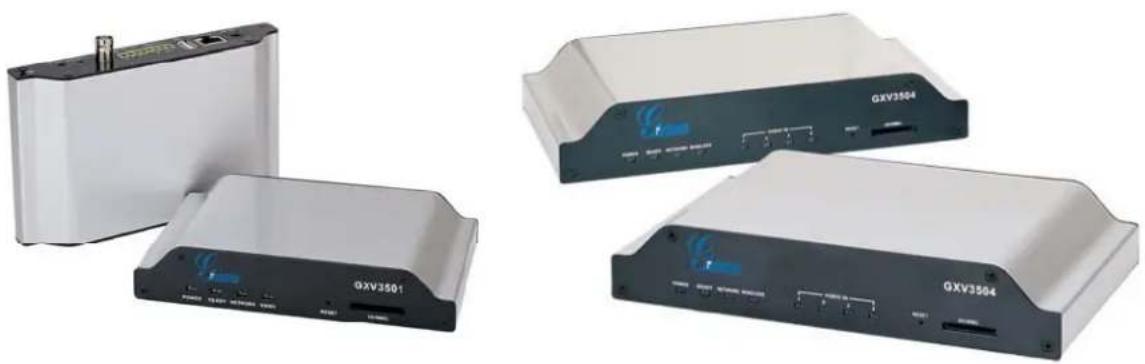
natural_image
Four different electronic devices labeled GXV3501, GXV3504, and a white rectangular device with a ports and antenna (no visible text or symbols on the devices themselves)Safety Instructions
These instructions are intended to assist users with the operation of the GXV3501/GXV3504 and also to instruct on how to avoid dangerous situations or damage to the device.
Warnings: Serious injury or death may be caused if any of the warnings below are neglected. Cautions: Injury or damage to the equipment may occur if any of the following caution messages are neglected.

Warnings Follow these safeguards to prevent serious injury or death.

Cautions Follow these precautions to prevent potential injury or material damage.

Warnings:
Input voltage should meet both the SELV (Safety Extra Low Voltage) and the Limited Power Source with DC 12V according to the IEC60950-1 standard. Please refer to the technical specifications for more details.
Do not use a third-party power adapter or power cord
When the device is installed on the wall or ceiling, make sure that it is firmly attached.

Notice:
Make sure that the power supply voltage is correct before using the camera.
Do not drop the device or expose it to physical shock.
Do not expose the device to temperatures outside the range of -10^ to +60^ when the device is in operation.
Do not expose the device to damp/wet conditions or high electromagnetism radiation.
To avoid heat accumulation, make sure that your operating environment has proper ventilation.
Do not attempt to open, disassemble, or modify the device
A few parts (e.g. electrolytic capacitor) of the equipment shall be replaced regularly according to their average life time. The average life time varies from the differences between operating environments and usage history. Regular maintenance checks are recommended for all users. Please contact your dealer for more details.
Contents
Welcome 4
Package Contents....5
Product Overview....7
GXV3501Front Panel 7
GXV3501Back panel....7
GXV3501 Sample Connection Diagram....8
GXV3504 Front Panel 8
GXV3504 Back Panel....9
GXV3504 Sample Connection Diagram....9
GXV3501/GXV3504 Key Features....10
Installation Guide....11
Minimum Recommended System Requirement ....11
Connect your GXV3501/GXV3504....11
Configuring the GXV3501/GXV3504 via Web Browser 13
Access GXV3501/GXV3504 Web Configuration Menu....13
Connect the Camera to DHCP server....13
Connect to the Camera using Static IP....13
GXV350x Home Web Page 14
GXV3501/GXV3504 System Page....16
GXV3501/GXV3504 Video & Audio Page 17
GXV3501/GXV3504 Networking Page – Assign an IP to GXV3501/GXV3504....18
GXV3501 Wifi Page....19
GXV3501/GXV3504 DDNS Page 20
GXV3501/GXV3504 SIP Page....20
GXV3501/GXV3504 Status Page....22
GXV3501/GXV3504 User Management Page....23
GXV3501/GXV3504 Maintenance Page....24
GXV3501/GXV3504 SMTP Page 25
GXV3501/GXV3504 FTP Page....25
GXV3501/GXV3504 PTZ Page 26
GXV3501/GXV3504 Alarm Event....27
GXV3501/GXV3504 Motion Detection....30
GXV3501/GXV3504 System Log....31
FAQ....33
Welcome
The GXV3501/3504 is a powerful, next generation digital video surveillance encoder. The GXV3501/3504 provides an easy to manage multi camera IP solution.
The GXV3501/3504 combines cutting-edge technology, including: support for SIP, H.264 BP, 2-way audio, and PoE, for best-in-class scalability, ease of integration and security. The unique incorporation of TCP/IP protocols creates sophisticated, flexible networking and remote control abilities.
The GXV3501/3504 features the advanced functionality of embedded analytics (including motion detection and video loss) and powerful pre-recording. Grandstream's flexible video management software enables users to monitor multiple environments in one easy to use application. The intuitive web interface lets users easily access, manage, view and record live video streams from the device.
The GXV3501/3504 is a robust surveillance solution for small to medium sized offices and enterprise environments.
Package Contents
Items in the GXV3501 package:
• GXV3501 – 1-channel digital video server
• 12V DC power Adapter
- 8-pin terminal block connector – 8-pin connector block for connecting external devices, such as infrared detector, and smoke detector, to Alarm IN, Alarm OUT and RS485 pins.
- Quick installation guide
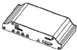
natural_image
Line drawing of a rectangular electronic device with ports and connectors (no text or symbols)GXV3501
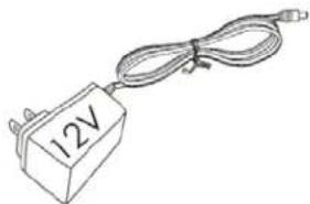
natural_image
Simple line drawing of a 12V power supply connected to a cable (no text or symbols)Power Adapter
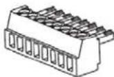
8-pin Terminal Block Connector

Quick Installation Guide
Items in the GXV3504 package:
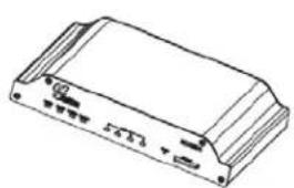
• GXV3504 – 4-channel digital video server
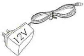
• 12V DC power Adapter
- 2 12-pin terminal block connectors – 12-pin connector block for connecting external devices, such as infrared detector, smoke detector, to Alarm IN, Alarm OUT, RS485 pins and etc.
- Quick installation guide
natural_image
Line drawing of a rectangular electronic device with ports and connectors (no text or symbols)GXV3504
natural_image
Simple line drawing of a 12V power connector with coiled cable (no text or symbols)Power Adapter
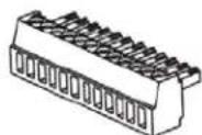
12 - pin Terminal Block Connector

Quick Installation Guide
Product Overview
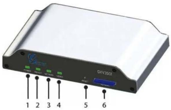
GXV3501Front Panel
1 POWER – The indicator will keep green if the power is on.
2 READY – The indicator will light up green if the device is ready.
3 NETWORK – The indicator will flash green if there is data transmission with the internet or stay solid green if there is no data transmission.
4 VIDEO – The indicator will light up green when there is video input.
5 RESET - Press the Reset button for 6 seconds to perform a factory reset.
6 SD/MMC – The SD/MMC slot.
GXV3501Back panel
1 DC 12V – 12V DC power port; UL Certified.
2 NETWORK – 10/100 Switch LAN port for connecting to Ethernet.
3 USB – USB port for flash / hard drives. Includes hot-swap support.
4 ALARM IN - 1 Alarm Input port for alarm equipment, ie. Infrared detector.
ALARM OUT - 1 Alarm Input port for detectors, ie. Sirens.
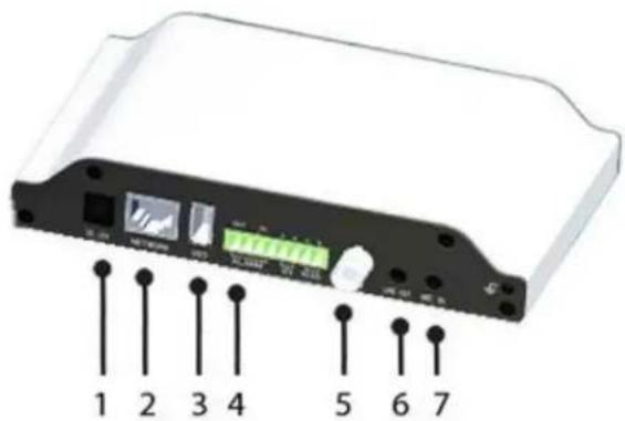
VG - 12V DC power output port for other devices.
RS-485 - 1 PTZ connector.
5 VIN - 1 BNC (Voltage: 1.0V p-p, Resistance 75Ω) port for video input3.5mm port for audio output devices, ie. Speakers.
6 LINE OUT - 3.5mm port for audio output devices, ie. Speakers.
7 MIC IN - 3.5mm port for audio input devices, ie. Microphones.
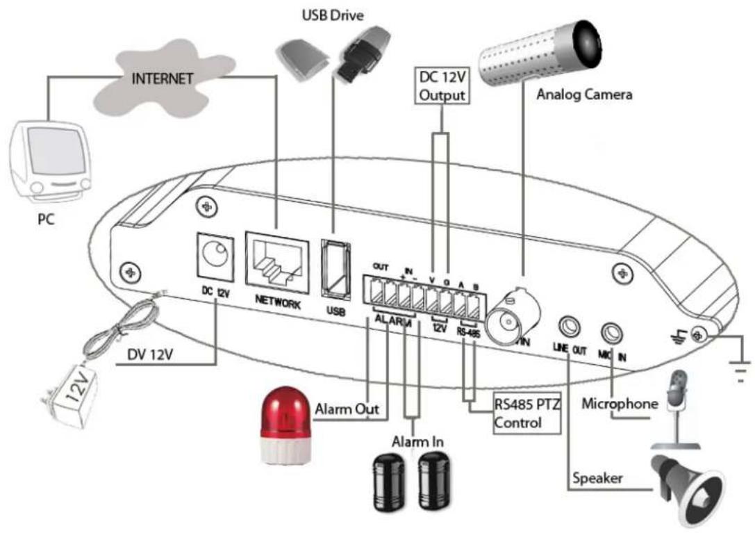
GXV3501 Sample Connection Diagram
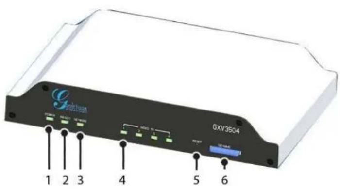
GXV3504 Front Panel
1 POWER – The indicator will stay green if power is on. 2 REDAY – The indicator will light up green if the device is ready. 3 NETWORK – The indicator will flash green if there is data. transmission with the internet or stay solid green if there is no data transmission.
4 VIDEO IN – 4 Video-In indicators. The indicators will light up green when video sources are
5 RESET – Press the Reset button for 6 seconds to perform a factory reset.
6 SD/MMC – The SD/MMC slot.
GXV3504 Back Panel
1 DC 12V – 12V DC power port; UL Certified.
2 NETWORK – 10/100 Switch LAN Ethernet port.
3 USB – USB port for USB flash / hard drives.
4 ALARM IN - 4 Alarm Input ports for alarm equipment, ie. Infrared / Smoke Detectors.
ALARM OUT-4 Alarm Input ports for detectors, ie. Sirens.
RS-485 - 1 PTZ connector.
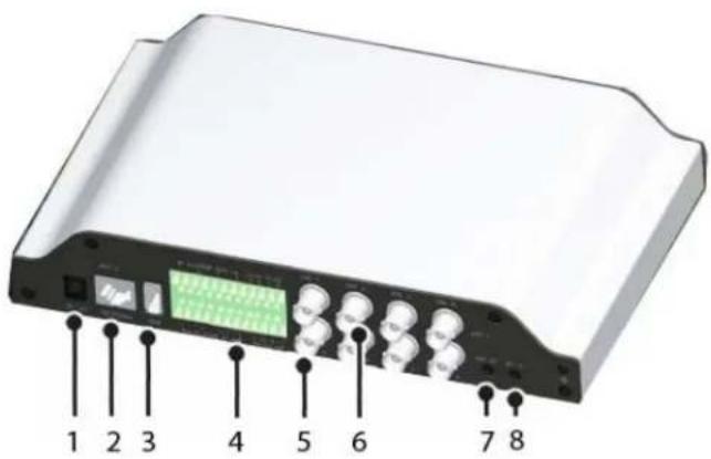
RS-232 – Persevered connectors.
VGGG - 12V DC power output port for other devices.
5 AIN - 4 BNC (Voltage: 1.0V p-p, Resistance 75 ) port for audio input.
6 VIN - 4 BNC (Voltage: 1.0V p-p, Resistance 75Ω) port for video input.
7 LINE OUT - 3.5mm port for audio output devices, ie. Speakers.
8 MIC-IN - 3.5mm port for audio input devices, ie. Microphones.
GXV3504 Sample Connection Diagram
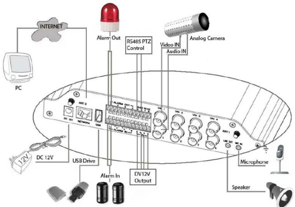
GXV3501/GXV3504 Key Features
The table below lists the key features the GXV3501/GXV3504 Supports.
| Feature | GXV3501 | GXV3504 |
| Channels | 1 4 | |
| Video Compression H.264 BP @Level 3.0, JPEG, Motion JPEG | ||
| Max Video Resolution | Full D1: 720 x 576(PAL) 720 x 480 (NTSC) | |
| Max Frame Rate in Max Video Resolution | 30fps/25fps at D1 (NTSC/PAL) 75fps/62.5fps (NTSC/PAL): 4 Ports at CIF at full rate, or 2 Ports at D1 & 2 Ports at CIF at full rate, or 4 ports at D1 at reduced rate | |
| Video Bit Rate 32 Kbps - 2 Mbps | ||
| Video Input 1 BNC | (voltage1.0Vp-p,resistance75) | 4 BNC (voltage 1.0Vp-p, resistance75) |
| Audio Input 3.5mm LINE IN 4 (BNC), 3.5mm LINE IN | ||
| Audio Output | 3.5mm LINEOUT | |
| Audio Compression G.711 | ||
| Alarm Input | 1 | 4 |
| Alarm Output | 1 | 4 |
| PTZ Control | Yes | |
| Serial Ports | RS485 | RS485/ RS232 |
| Embedded Analytics | Motion Detection (up to 16 target areas), video loss (pending) | |
| Pre-/post alarm buffer | 24MB | 24MB (per channel) |
| Snapshots | Can be sent via email/FTP when events are triggered. | |
| Multi-streaming-rate for Preview and Recording | Yes | |
| Security | Video watermark, HTTPS, password | |
| Power over Ethernet (PoE) | Standard, IEEE 802.3af Class 3 | |
| Peripheral Ports | SD 2.0, USB Host 2.0 | |
| SIP/VoIP Support | Yes | |
| Weight | 0.6kg | 1.0kg |
| Temperature / Humidity | -10oC - +55oC (14oF-131oF) Humidity 10-90% RH (non-condensing) | |
| Power | Output: 12VDC/1.5A; Input: 100-240VAC, 50-60Hz | |
| Compliance | FCC Part15, Subpart B Class B; EN 55022 Class B, EN61000-3-2, EN61000-3-3, EN 55024, EN60950-1; C-tick AS/NZS CISPR 22, CISPR 24 | |
Installation Guide
Minimum Recommended System Requirement
- Windows 2000 Server Professional, Windows XP, Windows Vista.
• CPU: Intel Pentium 4 or higher, 2 GHz.
• RAM: 1 GB (4 GB recommended for larger systems).
• Support for DirectX 8.0 and above.
Connect your GXV3501/GXV3504
Using the Power adapter as power supply
- Connect the video output of an analog camera to the VIN port on the GXV3501/3504 using a BNC (75Ω) cable. If the analog camera has audio output, connect the audio output to the AIN port on the GXV3504 (GXV3501 does not support audio input).
- Connect an RJ 45 cable to the NETWORK port of the GXV3501/3504
- Connect the other end of the RJ 45 cable to your network or PC directly
- Connect the power supply to the DC 12V power jack on the back of the GXV3501/3504
- Connect the other end of the power supply to a wall outlet. The POWER indicator will light green
- The NETWORK indicator will light green within 5 seconds to indicate that a connection to the internet has been established.
- The GXV3501/3504 is ready when the READY indicator lights up green.
- The VIDEO IN indicator will light up when the video inputs are connected to a video source.
Using PoE as power supply:
- Connect the video output of an analog camera to the VIN port on the GXV3501/3504 using BNC (75Ω) cable. If the analog camera has an audio output, you should connect it to the AIN port on GXV3504 (GXV3501 does not support audio input).
- Connect a RJ 45 cable to the NETWORK port of GXV3501/3504
- Connect the other end of the RJ 45 cable to a PoE switch. The POWER indicator will light solid green
- The NETWORK indicator will light green within 5 seconds to indicate that a connection to the internet has been established.
- The GXV3501/3504 is ready when the READY indicator is solid green
- The VIDEO IN indicator will light up when the video inputs are connected to a video source.
NOTE: If you are going to connect the device to a hub/switch/router, please use a
straight-through cable. A cross over cable should be used if you are going to connect the device directly to a PC.
Configuring the GXV3501/GXV3504 via Web Browser
The GXV3501/GXV3504's embedded Web server responds to HTTP/HTTPS GET/POST requests. Embedded HTML pages allow you to configure your IP camera through Microsoft Internet Explorer.
Access GXV3501/GXV3504 Web Configuration Menu
Connect the Camera to DHCP server.
- Navigate your browser to:
http://www.grandstream.com/support/gxv_series_surveillance/general/resources/gs_search.zip
- Run the Grandstream GS_Search tool, that you just downloaded.
- Click on Search button in order to begin device detection
- The detected devices will appear in the Output field
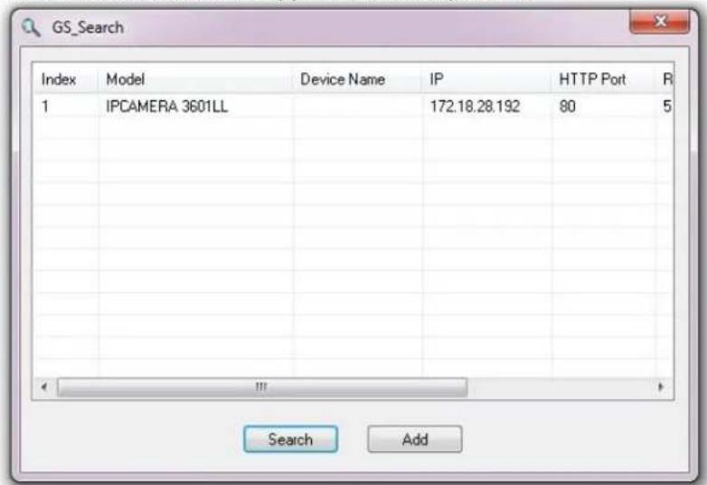
- Start Internet Explorer on your computer.
- Enter device IP in the address bar of the browser.
- Enter the administrator user name and password to access the Web Configuration Interface
- The default user name and password are both set to admin.
- IE will indicate that "This website wants to install the following add-on: 'GSViewerX.cab' from 'Grandstream Networks Inc'." Install this add-on by following the instructions in IE.
- You will see the home page.
Connect to the Camera using Static IP.
If the camera does not get response from DHCP server after 3 minutes, it can be accessed by the default IP 192.168.1.168.
- Connect your PC to the same network as the GXV3501/GXV3504.
- Configure the IP address of your PC to: 192.168.1.XXX (1<XXX<255) and configure the subnet mask to 255.255.255.0.
- Make sure that the device is turned on and connected to the network.
- Start Internet Explorer on your computer.
- Enter 192.168.1.168 in the address bar of the browser.
- Enter the administrator user name and password to access the Web Configuration Interface
- The default user name and password are both set to admin.
- IE will indicate that "This website wants to install the following add-on: 'GSViewerX.cab' from 'Grandstream Networks Inc'." Install this add-on by following the instructions in IE.
- You will see the home page.
GXV350x Home Web Page
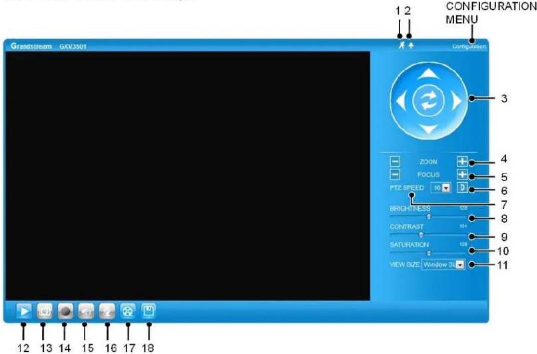
Figure2: Home web page of GXV3501
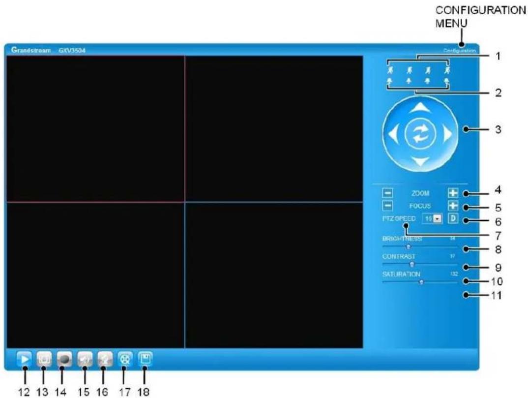
Figure3: Home web page of GXV3504
Items on GXV3501/GXV3504 Home Page
| 1 | Motion | Detection | If the motion detection alarm is triggered, the indicator will flash red. Click on the indicator to turn off the alarm. |
| 2 | Alarm | Event | If an alarm event is triggered, the indicator will flash red. Click on the indicator to turn off the alarm. |
| 3 | Control | Console | PTZ Console controller. PTZ device needs to be connected. |
| 4 | ZOOM | NOTE: GXV3501/GXV3504 does not support zoom | |
| 5 | FOCUS | Adjusts the focus of images. | |
| 6 | Default | Click this option to reset the video brightness, contrast, and saturation to their factory default configuration. | |
| 7 | SPEED | Adjusts the rotation speed of the console. | |
| 8 | BRIGHTNESS | Adjusts the image brightness. | |
| 9 | CONTRAST | Adjusts the image contrast. | |
| 10 | SATURATION | Adjusts the image saturation. | |
| 11 | View Size | Resize the image to fit into the window panel in the home scream. | |
| 12 | Play | Plays/Stops the video. | |
| 13 | Capture | Captures the image displayed and saves it to C:\GS_Capture | |
| (default directory). | ||
| 14 | Record | Records the video and saves it to C:\GS_Record (default directory). |
| 15 | Sound Off/On | Toggles the sound On or Off. |
| 16 | Talk | Establishes two-way audio. |
| 17 | Playback | Replays the saved video. |
| 18 | Config | Configures the Save Location for captured images and recorded videos. |
GXV3501/GXV3504 System Page
This page allows you to configure the system settings on GXV3501/GXV3504.
Current System Time - displays the current date and time (24h clock).
| Current System Time | |
| Date: | 2010-09-16 |
| Time: | 02:30:46 |
Set the System Time
Update via NTP Server
- the camera will obtain the time from an NTP server Specify the NTP server's IP address or host name. And you can select your time zone
| Set the System Time | |
| Time Zone: | GMT (Dublin, Lisbon, London, Reykjavik) |
| Update via NTP Server | |
| Synchronize with Local Computer | |
| Set the Time Manually | |
| Keep Current Date and Time | |
from the drop-down list or define your own time zone setting.
NOTE: If using a host name for the NTP server, a DNS server must be configured under
Basic Settings -> Networking.
Synchronize with Local Computer - sets the time from the clock on your computer.
Set the Time Manually - this option allows you to manually set the time and date.
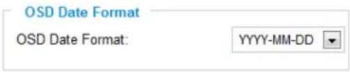
OSD Date Format - set the format of date on OSD
Device Name Setting -This field lets you configure the name of the GXV3501/GXV3504, which

helps GSurf and GS_NVR to indentify the device when using GS_Search to search all the
Grandstream network cameras or digit video cameras in the same subnet.
DI and DO - Digital input and digital output
Normal open: the circuit is by default open unless an event triggers the device to close the circuit.
DI and DO

Normal close: the circuit is by default closed
unless and event triggers the device to open the circuit
NOTE: GXV3504 has 4 individual DI/DO setting for each channel.
GXV3501/GXV3504 Video & Audio Page
On Screen Display (OSD) Settings
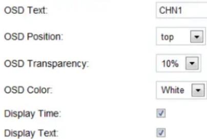
OSD Time/ Text – The time stamp and channel name displayed on the screen.
On Screen Display(OSD)
Video Settings
Preferred Video Codec – The GXV3501/GXV3504 supports the H.264 video codec.
Resolution - The higher the resolution is, the better the video quality is, and higher bandwidth is required.
Low ----→ High Resolution
QCIF CIF 2CIF D1
Bit Rate - The number of bits that are conveyed or processed per unit of time.
Maximum Frame Rate – The video frame rate is adjustable based on network conditions. Increasing the frame rate will increase the amount of data significantly therefore consuming more bandwidth. Video will be impaired due to packet loss when there is insufficient bandwidth.
Bit Rate Control – Variable Bit rate (VBR)
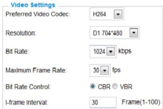
and Constant Bit Rate (CBR).
Variable Bit Rate - If VBR is selected, the codec varies the amount of output data per time segment. VBR produces a better quality-to-space ratio. The bits available are used to enable more flexibly and encode sound or video data more accurately, with fewer bits used in less demanding passages and more bits used in difficult-to-encode passages.
Constant Bit Rate - If CBR is selected, the codec's output data is constant regardless of the input data. The output bit rate is defined in "Bit rate". CBR is useful for streaming multimedia content on limited capacity channels. It is easier to calculate required bandwidth as well as the required storage space using CBR.
Image Quality – If 'Bit Rate Control' is set to "VBR", "Image quality" needs to be configured. The better the video quality is, the higher the bit rate will be.
I-frame Interval – While streaming video over a network, compression technologies are used to show the incremental difference between each frame. I-frames are used to help keep the video looking normal. When intervals are shorter, the video quality is higher but uses more bandwidth.
NOTE: The users might need to configure the Primary Stream and Secondary Stream properly. Sometimes, the user might like to watch the live video stream from the web GUI in low resolution mode while recording a copy via GSurf/GS_NVR in high resolution due to the limitation of internet bandwidth. In this case, for example, primary stream can be configured to have better resolution, and then the users can use primary stream to record while watching secondary video streams.
Audio Settings
Preferred Audio Codec – The GXV3501/GXV3504 supports up to 3 different Vocoder types,
a-law (PCMA), u-law (PCMU) and G.726.
The audio can also be turned off by switching the setting to "Disabled"
Audio Compression – Audio compression is a form of data compression designed to reduce the size
of audio files. Usually, the higher the audio compression is, the better the audio quality is.
Audio Settings
Preferred Audio Codec:
Audio Compression:
PCMA


kbps
NOTE: GXV3504 has 4 individual Video & Audio settings for each channel.
GXV3501/GXV3504 Networking Page – Assign an IP to GXV3501/GXV3504
GXV3501/GXV3504 supports IP version 4. The IP address can set automatically via DHCP, or a static IP address can be set manually. To make GXV3501/GXV3504 work properly, the user needs to set the DNS configuration properly. For security purposes, the user can also assign the GXV3501/GXV3504 an HTTP Port other than 80.
IP Address Configuration
The GXV3501/GXV3504 operates in two modes:
Dynamically Assigned via DHCP
– all the field values for the Static IP mode are not used. The GXV3501/GXV3504 acquires its IP address from the first DHCP server it discovers on its LAN.
Statically Configured as –
configures all of the following fields: IP address, Subnet Mask, Default Gateway IP address, DNS Server 1
IP Address Configuration
Dynamically Assigned via DHCP
- Statically Configured as:
IP Address: 192.168.40.191
Subnet Mask: 255.255.255.0
Default Gateway: 192.168.40.1
(primary), DNS Server 2 (secondary). These fields are set to zero by default. Static IP addresses are recommended for the GXV3501/GXV3504
DNS Configuration
There are two methods of DNS configuration on the
GXV3501/GXV3504:
- The GXV3501/GXV3504 can obtain the DNS server automatically
- Users can configure their own preferred DNS server
DNS Configuration
Obtain DNS Server Address Automatically
Use the Following DNS Server Address:
Primary DNS Server: 0.0.0.0
Secondary DNS Server: 0.0.0.0
HTTP Port
The GXV3501/GXV3504 supports user configured http ports. If the HTTP port is changed, the port number is needed to access the web GUI, for instance: http://192.168.1.168:8080.
HTTP
HTTP Port: 8080
NOTE: If the HTTP Port is 80, when you add this device to GSurf or GS_NVR, the RTSP port is 554. If the HTTP Port is changed, when you add this device to GSurf or GS_NVR, please make sure the RTSP port number equals HTTP Port plus 2000.
GXV3501 Wifi Page
GXV3501 supports WIFI via wireless dongles, not available on GXV3504.
Enable Wifi – Checked to enable Wifi
SSID – Click on Scan to view available network.
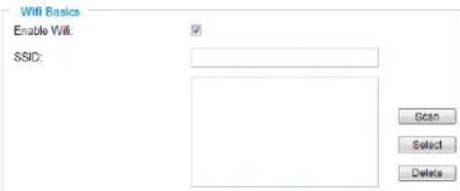
Choose a network and Click on Select to confirm.
Security Mode – Choose associated Security mode.

GXV3501/GXV3504 DDNS Page
Dynamic DNS provides devices that have a variable, often changing IP address with a well known hostname resolvable by network applications through standard DNS queries.
Set up DDNS
- Apply for a domain name from your service provider.
- Login to the web configuration page, click Basic Settings > DDNS.
- Enter the required information
DDNS Active – If you want to use DDNS, please set this field to "Enabled".
DDNS ISP Type - Select your DDNS ISP Type.
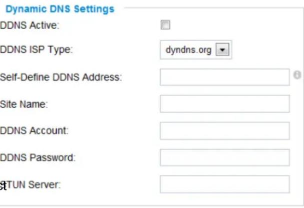
Self-Define DDNS Address – Self-define the DDNS server instead of using DDNS ISP Type.
Site Name – The DDNS name for your device.
DDNS Account/ DDNS Password – The account and password from the DDNS
P r o v i d e r .
STUN Server – If the device is behind a router, a STUN server is needed to help penetrate the NAT.
- Click Save to save the changes. You might need to reboot the device to apply all the changes.
GXV3501/GXV3504 SIP Page
The GXV3501/GXV3504 has the ability to receive phone calls and make phone calls when an alarm event is triggered through motion detection or alarm input. Register the GXV3501/GXV3504 to a SIP server to enable the product to make and receive phone calls.
To make outgoing phone calls out, the user needs to configure the Phone List properly.
NOTE: Pressing 1,2,3,4 buttons after the call is established to switching among channels on GXV3504.
Register GXV3501/GXV3504 to a SIP Server
- From the GXV3501/GXV3504 home page, click Basic Settings > SIP.
- Go to SIP Settings Tab.
- General Phone Settings.
Registered – The field shows the registration status of the account with the SIP server.
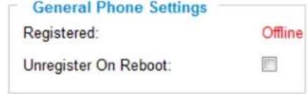
Unregister On Reboot – If it's checked, the SIP user's registration information will be cleared from the server when the phone reboots.
- Enter the required information.
Account Name – The field configures the SIP account name.
SIP Server – The SIP Server's IP address or Domain name provided by your service provider.
Outbound Proxy – The IP address or Domain name of the Outbound Proxy, Media Gateway, or Session Border Controller. Used for firewall or NAT penetration in different network environments. If the system detects a symmetric NAT, STUN will not work. ONLY outbound proxies can provide a solution for a symmetric NAT.
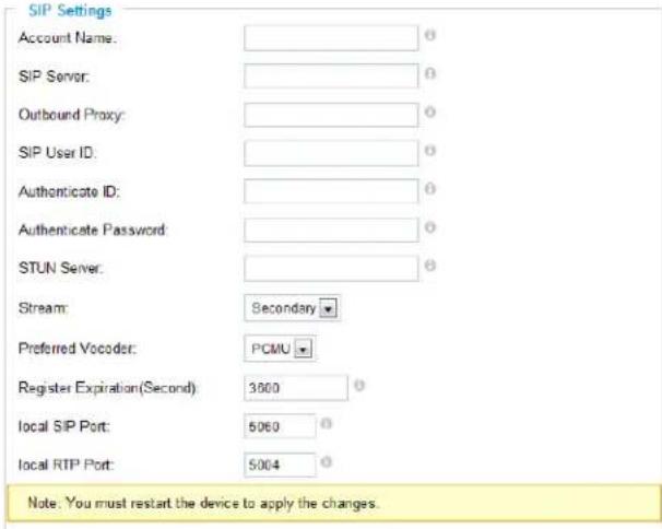
SIP User ID – User account information provided by your service provider (ITSP); this is either an actual phone number or is formatted like one.
Authenticate ID – The SIP service subscriber's Authenticate ID used for authentication. It can be identical to or different from the SIP User ID.
Authenticate Password – The SIP service subscriber's account password for the GXV to register to the SIP server of the ITSP.
STUN Server – If the device is behind a router, a STUN server is needed to help penetrate the NAT.
Stream – To choose between Primary and Secondary stream.
Preferred Vocoder – To choose different Vocoder type.
Registration Expiration – This parameter allows users to specify the time frequency (in minutes) in which the GXV refreshes its registration with the specified registrar. The default interval is 60 minutes.
Local SIP Port – This parameter defines the local SIP port used to listen and transmit.
The default value is 5060.
Local RTP Port – This parameter defines the local RTP-RTCP port pair that is used to listen and transmit. The default value is 5004.
- Click Save to save all the changes. You need to restart the device to apply all changes.
SIP Open Door Settings— Only applicable on GXV3501.
Enable SIP open door – This will close the DO connections in the back to close the circuit connected to it.
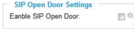
Key to open the door – DTMF key to close the circuit. Digits 0-9 only.
Delay lock time (seconds) – This is the time in seconds that the circuit will remain closed when this function is triggered
Configure Phone List Page
To make sure the GXV3501/GXV3504 can make phone calls to the number you preferred when alarm is triggered. You need to add number to the phone list.
Steps to add phone number:
- From the GXV3501/GXV3504 home page, click Basic Settings > SIP.
- Go to Phone List Tab.
- Enter the Phone number and name, click Add a Number to save all the changes.
- Numbers added to the system will be listed in this page.
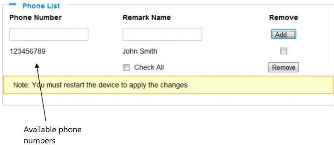
NOTE: With current firmware, only the first phone number in the list will be called when an alarm is triggered.
GXV3501/GXV3504 Status Page
System Statistics
System Statistics lists hardware and software information, for example, the part number, the software version, about the GXV3501/GXV3504.
Hardware Version – This field contains the product's hardware information.
Part Number – This field contains the product part number information.
Bootloader Version – Bootloader code version number.
Core Version – Core code version number.
Base Version – Base code version number.
Firmware Version – Firmware code version number.
System Statistics
| Product Model: | GXV3501 |
| Hardware Version: | V0.2B |
| Part Number: | 9650000502B |
| Bootloader Version: | 1.0.2.0 |
| Core Version: | 1.0.3.2 |
| Base Version: | 1.0.4.6 |
| Firmware Version: | 1.0.4.6 |
| System Up Time Since: | 53 minutes |
System Up Time Since – This field shows the system up time since the last reboot.
Network Status
MAC Address – The device ID, in HEXADECIMAL format.
LAN IP Address – This field shows the LAN IP address of the GXV3501/GXV3504.
LAN Subnet Mask – This field shows the LAN subnet mask of the GXV3501/GXV3504.
LAN Default Gateway – This field shows the LAN default gateway of the GXV3501/GXV3504.
Network Status
| MAC Address: | 00:0B:82:1D:D0:97 |
| LAN IP Address: | 192.168.40.171 |
| LAN Subnet Mask: | 255.255.255.0 |
| LAN Default Gateway: | 192.168.40.1 |
| DDNS Status: | Disabled |
| Wifi Status: | Disconnected |
DDNS Status – This field shows the status of DDNS.
GXV3501/GXV3504 User Management Page
All current users will be list in the User List section of this page. You can also add and remove users here.
Existing User Name –The field lists all of the current users. You can insert or remove users from the list by click on the Add or Update or Delete button.
User Name / Password – The user name and password
Manage User
| Existing User Name: | -Add New User- | |
| User Name: | ||
| User Password: | 0 | |
| Add | ||
| Confirm User Password: | Update | |
| Privilege: | Administrator | Delete |
| Allow Anonymous Viewing: | ✓ | Save |
required to login.
Privilege – The privilege for the user to access to configuration page.
Allow Anonymous Login – If 'Allow Anonymous Login' is set to Yes, no user name and password are required to login to the GXV3501/GXV3504 web configuration pages. If you login anonymously, you will not be able to change any settings.
GXV3501/GXV3504 Maintenance Page
Server Maintenance
Restart – Click this button to restart the GXV3501/GXV3504.
Restart the device
Restart the device.
Restore – Click this button to perform a partial factory reset (The IP address will not be cleared).
Restore the device
Reset settings, except IP address, to factory default.
Firmware Upgrade and Provisioning Items
Upgrade via – This field lets you choose the firmware upgrade method. The GXV3501/GXV3504 supports HTTP, HTTPS and TFTP.
Firmware Server Path – The IP address or domain name of the firmware server (the location of the firmware files).
Firmware Upgrade and Provisioning
| Upgrade via: | HTTP |
| Firmware Server Path: | 192.168.1.254 |
| Automatic Upgrade Interval(Minutes): | 10080 |
| Automatic Upgrade: | ✓ |
Automatic Upgrade Interval – Enter the frequency (in minutes) in which the
HTTP/HTTPS/TFTP server will be checked for new firmware upgrades or configuration changes.
Automatic Upgrade – The default setting is "No." Choose "Yes" to enable automatic.
HTTP/HTTPS/TFTP upgrade and provisioning. When set to "No", the IP Camera will only perform a HTTP/HTTPS/TFTP upgrade and perform a configuration check once during the boot process.
Performing a firmware upgrade:
-
Download the firmware package from http://www.grandstream.com/firmware.html.
-
Unzip the firmware package and copy the files to the firmware upgrade server directory.
Upgrades are supported via TFTP, HTTP and HTTPS.
-
Log in to the Maintenance page of the GXV3501/GXV3504. Select the server type from the dropdown list under the "Upgrade Via" field. Enter your server's root directory in the "Firmware Server Path" field.
-
Reboot the GXV3501/GXV3504 to begin the firmware upgrade process.
GXV3501/GXV3504 SMTP Page
The SMTP server is used to send out emails when an alarm event or motion detection is triggered. The SMTP settings must be configured to make sure the alarm email is sent out properly.
SMTP Server Settings
Enable SMTP – Checked to enable SMTP SMTP Server – The IP or hostname of the SMTP server, for example, smtp.gmail.com.
SMTP Server Port – The port of the SMTP server. The GXV3501/GXV3504 supports port 25 and SSL port 465, which is for SMTP with an encrypted connection.
From E-Mail Address – The email address that sends out the alarm email(s).
To E-Mail Address – The email addresses that the alarm email(s) will be sent to. You can have up to 3 emails configured.
User Name/ Password – The user name and password required to log in to your SMTP server, for example, 123@gmail.com/123.
SMTP Server Settings
Enable SMTP:
SMTP Server:
SMTP Server Port:
From E-Mail address:
To E-Mail address 1:
To E-Mail address 2:
To E-Mail address 3:
User Name:
Password:
SSL:

smtp.gmail.com
465
XXX@gmail.com
YYY@gmail.com
ZZZ@gmail.com
XXX@gmail.com

√ ①
^1 Required Fields.
^2 Valid DNS server is required for hostname.
Save Test
SSL – Checked if the SMTP server requires a secure connection.
Test Email Account Settings – Click the Test button to send a test email from the From E-Mail to the To E-Mail to make sure that SMTP is configured properly. If the receiver can get the test email, then the SMTP settings are ready to go.
GXV3501/GXV3504 FTP Page
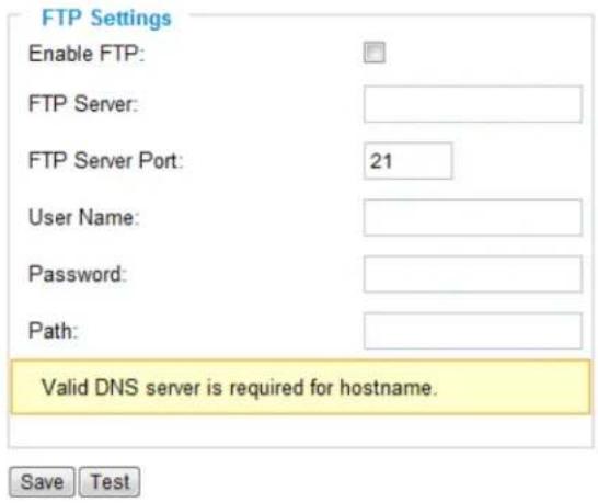
The FTP server is used to store video files if you configure the GXV3501/GXV3504 to record video and upload it to the FTP server when an alarm event or motion detection is triggered.
FTP Settings
Enable FTP – The default setting is "No," if you want the GXV3501/GXV3504 to upload the recorded video to the FTP server when an alarm is triggered, set this field to "Yes."
FTP Server – The IP address or hostname of the SMTP server, ie. ftp.myserver.com. FTP Server Port – The port that your FTP server is using.
User Name / Password – The user name and password required to log into your FTP server
Path – The directory in the FTP server where recorded video will be uploaded.
Test FTP Account Settings – Click the Test button to upload a sample file to make sure that FTP is properly configured.
GXV3501/GXV3504 PTZ Page
This page configures the PTZ settings. Select the PTZ protocol that your connected equipment supports by clicking on the radio in front of the protocol. Next, select the Baudrate from the drop down menu.
PTZ Configuration Items
PTZ Protocol – The GXV3501/GXV3504 supports both Pelco-D and Pelco-P. Select the protocol your PTZ equipment supports.
PTZ Baudrate – The Baud rate is the number of distinct symbol changes
(signaling events) made to the transmission medium per second in a digitally modulated signal or a line code.
PTZ Settings
Protocol:
Baudrate:

Pelco-P Pelco-D
9600 bit/s

Connect a PTZ device to the GXV3501/GXV3504
- Connect the PTZ device to GXV3501/GXV3504 by following the connection diagram shown below
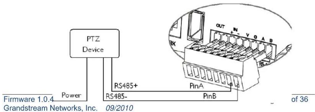
- Click Advanced Settings > PTZ; in PTZ page, configure the PTZ Protocol and Baudrate according to your connected PTZ device.
- Click Save and reboot the device to apply all changes.
- Use those PTZ buttons on the homepage to tilt, pan the GXV3501/GXV3504 and also adjust the speed.
NOTE: Press and hold the corresponding control button to adjust the pan, tilt, zoom and speed.
GXV3501/GXV3504 Alarm Event
The GXV3501/GXV3504 supports alarm inputs, for example, infrared detector, smoke detector and so on. Follow the steps to make Alarm Input work:
- Connect alarm input equipment to the GXV3501/GXV3504.
- Set up the alarm event time schedule.
- Configure the alarm actions which you would like the GXV3501/GXV3504 to take when alarm is triggered.
NOTE: GXV3504 has 4 individual Alarm Event settings for each channel.
How Alarm Input and Alarm Output Work
Alarm-in is the alarm input port; users are able to connect sensors such as infrared sensor, smoke sensor or light sensor to it. The detectable signal voltage range for alarm-in is from 1.8V to 15 V NOTE: Please do not connect a device that has a signal voltage that is higher than 15V, this will damage the IP camera.
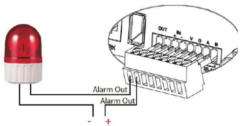
Internally, the Alarm-out uses relays as a switch (30VAC/2A); users can connect devices such as alarm siren or alert light to this port. Under normal circumstances, the circuit is open.
When there is an alarm event, the GXV3501/GXV3504 will close the circuit to trigger the alarm.
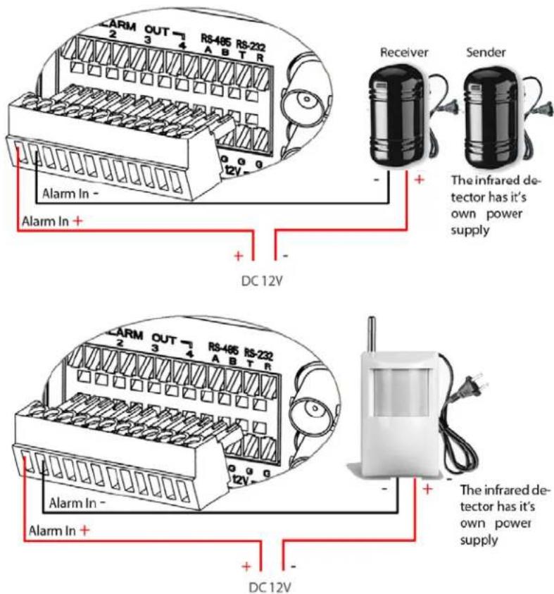
Connect Alarm Input Equipment to the GXV3501/GXV3504
Here are two sample connection diagrams. Connect the alarm equipment to the GXV3501/GXV3504 by following the diagram below.
Set up Alarm Actions
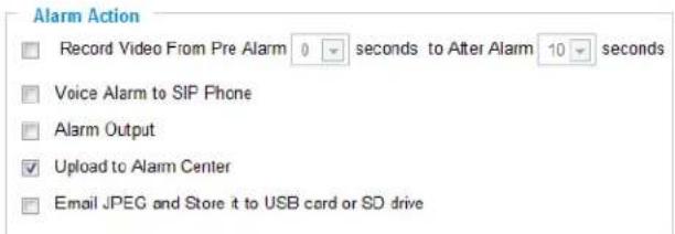
An alarm action is what the GXV3501/GXV3504 is going to do when an alarm is triggered during the defined time period – the time schedule. The GXV3501/GXV3504 allows multiple alarm actions.
Record Video – If this option is selected, the GXV3501/GXV3504 will record the video when an alarm is triggered. You can enter the length of the video recording (in seconds). You can also choose the storage method for video files: SD card, USB Flash drive, or USB hard drive.
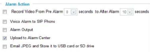
Voice Alarm to SIP Phone – If this option is selected, the GXV3501/GXV3504 will make calls to the number listed in the Phone List page using the configured SIP account when an alarm is triggered. To use this function, the settings in SIP page must be configured properly.
Alarm Output – If this option is selected, the alarm will output via the configured method/equipment when it is triggered.
Upload to Alarm Center – This option is an integrated feature with GSurf. If this option is checked, the GXV3501/GXV3504 will report the alarm event to GSurf.
Record Video and Upload to FTP server – If this option is selected, the
GXV3501/GXV3504will record the video and upload it to the FTP server when an alarm is triggered. You must check Record Video and configure the FTP page properly to use this feature.
Email JPEG and Store it to USB drive or SD card – If this option is selected, the
GXV3501/GXV3504 will capture the image and store it to connected live storage device when an alarm is triggered.
Set up Alarm Event Time Schedule
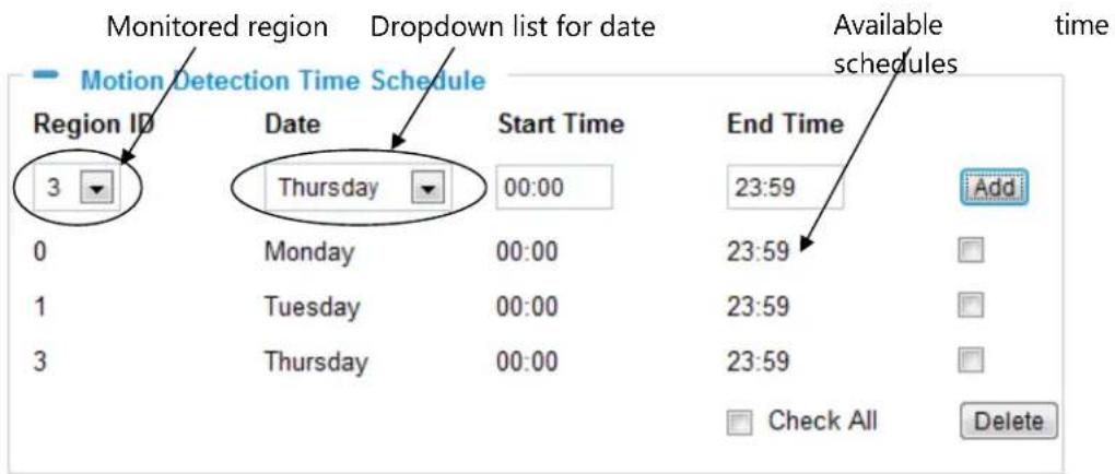
This section allows you to configure the time during which the GXV3501/GXV3504 will monitor the Alarm Input. The GXV3501/GXV3504 can not only monitor your settings but can also take actions when the alarm is triggered.
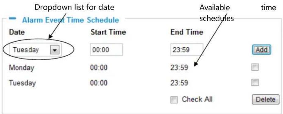
To add a schedule, select the date from the dropdown list, Start Time and End time and Click Add to add a new time schedule.
To delete a schedule, check the schedule you would like to remove and click Delete.
How to connect an Alarm Output Equipment to GXV3501/GXV3504 Here is a sample connection diagram. Connect the alarm output equipment to the GXV3501/GXV3504 by following the diagram below.
GXV3501/GXV3504 Motion Detection
The GXV3501/GXV3504 supports Motion Detection. To utilize this feature, please follow the below steps:
- Setup the motion detection monitored area.
- Configure the motion detection time schedule.
- Configure alarm action properly.
NOTE: GXV3504 has 4 individual Motion Detection settings for each channel.
Setup Motion Detection Monitored Area
Enable Motion Detection – If this option is selected, motion detection will be enabled. If something/somebody moves in the motion detection region, an alarm will be triggered.
Show Motion Detection Regions – If this option is selected, the motion detection regions will be displayed on the screen with a white border.
The white border for Motion Detection Regions
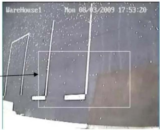
NOTE: If Upload to Alarm center is checked for Alarm Actions, the white border will flash red when a motion detection alarm is triggered.
To Edit a Monitored Area
- In the Select a Region dropdown list, select the region ID.
- Click Edit.
- Click on the video, drag and draw you preferred area.
- Set the Sensitivity. Click the Save button to save the sensitivity.
NOTE: The Sensitivity value varies from 0 to 100. The larger the value is, the higher the sensitivity.
- Click Save to save the settings.
Motion Detection Region Settings
√ Enable Motion Detection
Show Motion Detection Regions
0 Select a Region
50 Sensitivity Save
Edit Remove Save
Button to save sensitivity only
To Remove a Monitored Area
-
In the Select a Region dropdown list, select the region you would like to remove.
-
Click Remove.
- Click Save to save the changes.
Configure Motion Detection Alarm Actions
An alarm action is what the GXV3501/GXV3504 is going to do when an alarm is triggered
during the defined time period – the time schedule. The
GXV3501/GXV3504 allows multiple alarm actions.
Configure Motion Detection Time Schedule
This section allows you to configure the time during which the GXV3501/GXV3504 will monitor the motion detection. The GXV3501/GXV3504 not only can monitor your settings but also can take actions when the alarm is triggered.
GXV3501/GXV3504 System Log
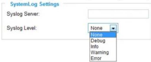
This page is used to set up the system log server path and system log level. Once they are correctly configured, the device will send out system log messages to the system log server,
which will help perform troubleshooting.
Syslog Server – The IP address or URL of System log server.
Syslog Level – Select the device to report the log level. Default is None. The level is one of Debug, Info, Warning or Error.
GXV3501/GXV3504 Live Storage
This page displays detailed information of the live storage devices connected to the GXV3501/GXV3504 such as video and image files. You can view, download or delete the stored files.
Storage Information – This section displays the type, capacity, used space, free space and
usage percentage of the connected USB drive or SD card.
| Storage Information | |||||
| Type | Capacity | Used Space | Free Space | Use(%) | Umount |
| USB | 7.5G | 2.3M | 7.5G | 0.03% | Umount |
JPEG List – This section displays the name, source storage and size of the image files on
the connected storage devices. You can view, download or delete the stored files.
| JPEG List | ||||||
| File Name | Size | View | Check | |||
| 192.168.40.191_chn1_2010_09_16_07_32_16.jpg | 87.1k | |||||
| Pages:1 | Total:1 | Index:1-1 | Goto: 1 Page | Check All | Delete | |
Video List – This section displays the name, source storage and size of the video files on the
connected storage devices. You can view, download or delete the stored files.
| Video List | ||||||
| File Name | Size | Download | Check | |||
| 192.168.40.191_chn1_2010_09_16_07_31_38_1_15.avi | 2.1M | |||||
| Pages:1 | Total:1 | Index:1-1 | Goto: 1 Page | Check All | Delete | |
IP VIDEO SURVEILLANCE FAQ
1. What is the default IP address of GXV3501/GXV3504/3501/3504?
Prior to firmware version 1.0.3.9, the IP address of GXV3501/ 3504/ 3601/ 3611 is 192.168.1.168 at the factory default settings. You can perform a factory reset by pressing the RESET button on the device for 7 seconds. Starting from firmware version 1.0.3.9, the default IP configuration is DHCP.
2. Why can I not view the live video stream in Microsoft Internet Explorer?
Please check whether the IE add-on is installed correctly.
Once you log into the GXV3501/ 3504 / 3601's web interface Internet Explorer will indicate that "This website wants to install to following add-on: 'GSViewer. cab' from Grandstream Networks, Inc.". Please install this add-on when prompted by IE.
3. How do you manually uninstall the Grandstream video viewer add-on for IE?
Please follow these steps to uninstall the add-on:
- Delete the GSViewerX Control from C:\WINDOWS\Downloaded Program Files directory
- Delete GSNetClient.dll, GS_Replay.exe, GSViewerX.ocx, hi_h264dec_w.dll, lik_VoiceEngine_dll.dll and GSViewerX.inf from C:\WINDOWS\system32
4. Why can't I access the GXV3501/ 3504/ 3601 web configuration interface?
Q 1: Is your internet service down?
A 1: Connect a PC to the internet to test the connection.
Q 2: Are the PC and the device in different subnets?
A 2: Check the subnet mask and default gateway of the device and PC.
Q 3: Is there a conflict with another IP address?
A 3: Try to change the IP address of the device.
Q 4: Has the HTTP port been changed?
A 4: Contact the administrator of the device for more information.
5. The GXV3501/ 3504/ 3601 web configuration page is not displayed correctly in Internet Explorer 8?
In IE8, Compatibility View might need to be enabled for the GXV3501/ 3504/ 3601 web configuration page to load properly. To enable compatibility view, open IE8, click Tools>Compatibility View Setting, and add the GXV3501/ 3504/ 3601 web configuration pages to the Compatibility View.
6. Why does IE indicate to install Grandstream Video Viewer add-on after a firmware upgrade? The add-on was properly installed before the firmware upgrade process.
New firmware will often upgrade the add-on as well. To watch the live video stream, you must install the newest version of the add-on.
7. How do you watch secondary video stream?
Login to the home page of the GXV3501/ 3504/ 3601 web GUI, click Play to watch the video stream. To watch a secondary video stream, right click on the video, and select Secondary Stream on the pop-up menu. Try reinstalling the Grandstream Viewer add-on for IE if you cannot see the video stream.
8. Why is audio missing from the recorded video when an alarm is triggered?
Please double check whether the device has an audio input connected.
The GXV3504 has 4 audio input ports and one MIC IN port. The GXV3501 has a MIC IN port for an audio input. The GXV3501/GXV3504 has a built-in microphone and one MIC IN port for audio inputs.
9. What is DDNS? Is it important for IP surveillance product to have DDNS support?
DDNS is an acronym for Dynamic Domain Name Service. It is important to choose an IP network camera that has DDNS support for dynamic IP addresses.
Chances are that the network has a dynamic IP address (which changes with every log on). A DDNS service makes sure that the camera's IP address always matches up to the current server address. DDNS also allows for a website to be linked to the IP camera that is constantly updated with the correct information and has a reliable feed.
10. Why is Windows Media Player unable to play the recorded videos files?
The GXV3501/3601/3504 all use the H.264 video codec. Windows Media Player may lack the proper H.264 decoder to play the recorded video. Please download the Microsoft FFDShow H.264 decoder from http://sourceforge.net/projects/ffdshow-tryout/ and install it.
11. Alarm Triggered Events do not work in GSurf.
Please double check the Alarm Action on your GXV3501/ 3504/ 3601. Login to the web GUI of the GXV3501/ 3504/ 3601, go to the Motion Detection or Alarm Events page, and make sure option Upload to Alarm Center is checked.
12. It is recommended that you save your video files in different directories when using GSurf and GS\_NVR.
GSurf and GS_NVR are different programs that have the ability to delete recorded video files. It is better to save video files in different directories when using GSurf and GS_NVR in the event that they automatically delete files that you might want to keep.
13. How can I use a cell phone to watch the GXV3501/ 3504/ 3601 video stream?
You must set the video resolution to QCIF to watch the GXV3501/3504 /3601 video stream from a cell phone. Make sure to set the bit rate to 64kbps to ensure the best video quality.
14. Why doesn't the IP address of the device reset when I click the "Restore" button on the Maintenance page?
The GXV3501 /3504 /3601 could be installed in areas that are not easy to access. For example, it could be installed on the roof of a building or the ceiling of an office. This makes it difficult to reinstall the device, therefore the "Restore" function will not clear the IP address. Press the RESET button on the device for at least 6 seconds until you hear a beep to perform a factory reset of all parameters (including the IP address).
15. Why can't the live video stream be viewed using a mobile phone or GSurf after changing the HTTP Port of the device?
Make sure that the RTSP port of the device is set to 2000 plus the HTTP Port number. For example, if the HTTP port is 88, then the RTSP port of the device that you configured on GSurf / mobile phone should be 2088.
16. Some notes on using SD cards / USB drives.
- The GXV3501/ 3504/ 3601 only supports FAT32 formatted USB drives
- The GXV3501/ 3504/ 3601 support SD and SDHC
- It takes 10-15 seconds to read SDHC and USB drives with large memory capacities. Please wait 15 seconds to unplug the SD/USB drive after you plug them into the device.
- If there are many files (ie. 1800 or more image batch files) on the SD/USB drive, it can take up to 5 minutes to read them. Please do not refresh the web interface at this time as the GXV3501/3504 will restart reading the SD/USB drive. Grandstream is currently working on a fix for this issue.
5. Why is there a black / flashing bar at the bottom of the video feed?
This can occur if the GXV3501 /3504 does not recognize the standard of the connected camera. If you experience this issue, please restart the GXV3501 /3504. The GXV3501 /3504 will detect the standard of the connected camera and use it when the GXV3501 /3504 boots up. To avoid this make sure to connect analog cameras before booting up the GXV3501 /3504.
6. Port forwarding
Two ports must be forwarded on your router to watch video from a GXV3501 /3504 /3601/3611 that is located on a private network from a PC in a public network. The web port (HTTP) and the RTSP port. Please make note that the RTSP port number changes according to the web port. If the web port is 80, then the RTSP port is 554. If the web port is not 80, then
the RTSP port equals the web port +2000. For example, if the web port is 88, then the RTSP port will be 2088.
- Tested PC display adapters.
| Display Adapter Test Result | |
| SiS 650/651/740/661 FX/741/760 Series Works normally | |
| Intel(R) 82945R Express Chipset Family Works normally | |
| VIA/S3G UniChrome Pro IGP Works normally | |
| NIVDIA Geforce 7300GS Works normally | |
| SiS 661FX Works normally | |
| SiS Mirage Graphics Works normally | |
| SiS 661 Series Works normally | |
| Intel(R) G33/G31 Express Works normally | |
| SiS Mirage3 Graphics Works normally | |
| SiS 661FX/GX Mirage Graphics | Works normally |
| S3 Graphics ProSavageDDR(Microsoft Corporation) | Works normally |
| XGI Velari Z7/Z9/Z9S V1.08.12 | There is some delay when playing videos. |
| Intel 965 Express Chipset Family | Works normally |
| ATI Mobility Radeon X1300 | Works normally |
| Intel( R ) G45/G43 Express Chipset | Works normally |
| Mobile Intel 965 Express Chipset Family Works normally | |
| Mobile Intel(R) 4 Series Express Chipset Family | Works normally |
| Mobile Intel® 945GM Express Chipset Family | Works normally |
| Mobile intel® 915GM/GMS, 910GML Express Chipset Family | Works normally |
| Intel® G45/G43 Express Chipset | Works normally |
| ATI Technologies, RAGE XL PCI | This display adapter cannot display videos. |
- Grandstream Networks, Inc.
- GXV3501/GXV3504 User Manual
- Safety Instructions
- Warnings:
- Notice:
- Contents
- Welcome
- Package Contents
- Items in the GXV3501 package:
- Items in the GXV3504 package:
- Product Overview
- GXV3501Front Panel
- GXV3501Back panel
- GXV3504 Front Panel
- GXV3504 Back Panel
- GXV3501/GXV3504 Key Features
- Installation Guide
- Minimum Recommended System Requirement
- Connect your GXV3501/GXV3504
- Using the Power adapter as power supply
- Using PoE as power supply:
- Configuring the GXV3501/GXV3504 via Web Browser
- Access GXV3501/GXV3504 Web Configuration Menu
- Connect the Camera to DHCP server.
- Connect to the Camera using Static IP.
- Items on GXV3501/GXV3504 Home Page
- GXV3501/GXV3504 System Page
- Set the System Time
- Update via NTP Server
- GXV3501/GXV3504 Video & Audio Page
- On Screen Display (OSD) Settings
- Video Settings
- Audio Settings
- GXV3501/GXV3504 Networking Page – Assign an IP to GXV3501/GXV3504
- IP Address Configuration
- Dynamically Assigned via DHCP
- Statically Configured as –
- DNS Configuration
- HTTP Port
- HTTP
- GXV3501 Wifi Page
- GXV3501/GXV3504 DDNS Page
- Set up DDNS
- GXV3501/GXV3504 SIP Page
- Register GXV3501/GXV3504 to a SIP Server
- Configure Phone List Page
- GXV3501/GXV3504 Status Page
- System Statistics
- Network Status
- GXV3501/GXV3504 User Management Page
- GXV3501/GXV3504 Maintenance Page
- Firmware Upgrade and Provisioning Items
- Performing a firmware upgrade:
- GXV3501/GXV3504 SMTP Page
- SMTP Server Settings
- GXV3501/GXV3504 FTP Page
- FTP Settings
- GXV3501/GXV3504 PTZ Page
- PTZ Configuration Items
- PTZ Settings
- Connect a PTZ device to the GXV3501/GXV3504
- GXV3501/GXV3504 Alarm Event
- How Alarm Input and Alarm Output Work
- Set up Alarm Actions
- Set up Alarm Event Time Schedule
- GXV3501/GXV3504 Motion Detection
- Setup Motion Detection Monitored Area
- To Edit a Monitored Area
- Motion Detection Region Settings
- To Remove a Monitored Area
- Configure Motion Detection Alarm Actions
- Configure Motion Detection Time Schedule
- GXV3501/GXV3504 System Log
- GXV3501/GXV3504 Live Storage
- IP VIDEO SURVEILLANCE FAQ
- What is the default IP address of GXV3501/GXV3504/3501/3504?
- Why can I not view the live video stream in Microsoft Internet Explorer?
- How do you manually uninstall the Grandstream video viewer add-on for IE?
- Why can't I access the GXV3501/ 3504/ 3601 web configuration interface?
- The GXV3501/ 3504/ 3601 web configuration page is not displayed correctly in Internet Explorer 8?
- Why does IE indicate to install Grandstream Video Viewer add-on after a firmware upgrade? The add-on was properly installed before the firmware upgrade process.
- How do you watch secondary video stream?
- Why is audio missing from the recorded video when an alarm is triggered?
- What is DDNS? Is it important for IP surveillance product to have DDNS support?
- Why is Windows Media Player unable to play the recorded videos files?
- Alarm Triggered Events do not work in GSurf.
- It is recommended that you save your video files in different directories when using GSurf and GS\_NVR.
- How can I use a cell phone to watch the GXV3501/ 3504/ 3601 video stream?
- Why doesn't the IP address of the device reset when I click the "Restore" button on the Maintenance page?
- Why can't the live video stream be viewed using a mobile phone or GSurf after changing the HTTP Port of the device?
- Some notes on using SD cards / USB drives.
- Why is there a black / flashing bar at the bottom of the video feed?
- Port forwarding
Brand : GRANDSTREAM
Model : GXV3504
Category : Security Camera